SECTION SUPPLEMENTAL RESTRAINT SYSTEM (SRS) filesrs-1 supplemental restraint system (srs) h...
62
SRS-1 SUPPLEMENTAL RESTRAINT SYSTEM (SRS) H RESTRAINTS CONTENTS C D E F G I J K L M SECTION A B SRS PRECAUTIONS ......................................................... 3 Precautions for Supplemental Restraint System (SRS) “AIR BAG” and “SEAT BELT PRE-TEN- SIONER” ................................................................. 3 Precautions for SRS “Air Bag” and “Seat Belt Pre- tensioner” Service ................................................... 3 After A Collision ....................................................... 4 Wiring Diagrams and Trouble Diagnosis ................. 4 PREPARATION .......................................................... 5 Special Service Tools .............................................. 5 SRS CONFIGURATION ............................................. 6 Description .............................................................. 6 SRS Component Parts Location ............................. 7 Direct-connect SRS Component Connectors .......... 7 TROUBLE DIAGNOSIS ............................................. 8 Trouble Diagnoses Introduction .............................. 8 DIAGNOSIS FUNCTION ...................................... 8 DIAGNOSIS MODE FOR CONSULT-II ................ 8 HOW TO CHANGE SELF-DIAGNOSIS MODE WITH CONSULT-II ............................................... 9 HOW TO CHANGE SELF-DIAGNOSIS MODE WITHOUT CONSULT-II ....................................... 9 HOW TO ERASE SELF-DIAGNOSIS RESULTS ..... 9 How to Perform Trouble Diagnoses for Quick and Accurate Repair ..................................................... 11 INFORMATION FROM CUSTOMER .................. 11 PRELIMINARY CHECK ...................................... 11 WORK FLOW ..................................................... 12 Schematic ............................................................. 13 Wiring Diagram — SRS — .................................... 14 SRS Operation Check ........................................... 18 DIAGNOSTIC PROCEDURE 1 .......................... 18 Trouble Diagnoses with CONSULT-II .................... 19 DIAGNOSTIC PROCEDURE 2 .......................... 19 DIAGNOSTIC PROCEDURE 3 .......................... 22 DIAGNOSTIC PROCEDURE 4 (CONTINUED FROM DIAGNOSTIC PROCEDURE 2) ............. 25 DIAGNOSTIC PROCEDURE 5 .......................... 25 Trouble Diagnoses without CONSULT-II ............... 29 DIAGNOSTIC PROCEDURE 6 .......................... 29 DIAGNOSTIC PROCEDURE 7 .......................... 34 DIAGNOSTIC PROCEDURE 8 (CONTINUED FROM DIAGNOSTIC PROCEDURE 6) ............. 36 Trouble Diagnoses: “AIR BAG” Warning Lamp Does Not Turn Off ........................................................... 37 DIAGNOSTIC PROCEDURE 9 .......................... 37 Trouble Diagnoses: “AIR BAG” Warning Lamp Does Not Turn On ........................................................... 38 DIAGNOSTIC PROCEDURE 10 ........................ 38 DIAGNOSIS SENSOR UNIT .................................... 39 Removal and Installation ....................................... 39 CRASH ZONE SENSOR .......................................... 40 Removal and Installation ....................................... 40 SIDE AIR BAG (SATELLITE) SENSOR .................. 41 Removal and Installation ....................................... 41 REMOVAL .......................................................... 41 INSTALLATION .................................................. 41 FRONT SEAT BELT PRE-TENSIONER .................. 42 Removal and Installation ....................................... 42 DRIVER AIR BAG MODULE AND SPIRAL CABLE ... 43 Removal and Installation ....................................... 43 REMOVAL .......................................................... 43 INSTALLATION .................................................. 45 FRONT PASSENGER AIR BAG MODULE ............. 47 Rmoval and Installation ......................................... 47 REMOVAL .......................................................... 47 INSTALLATION .................................................. 49 SIDE CURTAIN AIR BAG MODULE ....................... 50 Removal and Installation ....................................... 50 REMOVAL .......................................................... 50 INSTALLATION .................................................. 51 DISPOSAL OF AIR BAG MODULE AND SEAT BELT PRE-TENSIONER .................................................... 52 Disposal of Air Bag Module and Seat Belt Pre-ten- sioner ..................................................................... 52 CHECKING DEPLOYMENT TOOL .................... 52 DEPLOYMENT PROCEDURES FOR AIR BAG MODULE (OUTSIDE OF VEHICLE) .................. 53 DEPLOYMENT OF AIR BAG MODULE AND SEAT BELT PRE-TENSIONER WHILE
Transcript of SECTION SUPPLEMENTAL RESTRAINT SYSTEM (SRS) filesrs-1 supplemental restraint system (srs) h...

SRS-1
SUPPLEMENTAL RESTRAINT SYSTEM (SRS)
H RESTRAINTS
CONTENTS
C
D
E
F
G
I
J
K
L
M
SECTION
A
B
SRS
PRECAUTIONS .......................................................... 3Precautions for Supplemental Restraint System (SRS) “AIR BAG” and “SEAT BELT PRE-TEN-SIONER” .................................................................. 3Precautions for SRS “Air Bag” and “Seat Belt Pre-tensioner” Service .................................................... 3After A Collision ........................................................ 4Wiring Diagrams and Trouble Diagnosis .................. 4
PREPARATION ........................................................... 5Special Service Tools ............................................... 5
SRS CONFIGURATION .............................................. 6Description ............................................................... 6SRS Component Parts Location .............................. 7Direct-connect SRS Component Connectors ........... 7
TROUBLE DIAGNOSIS .............................................. 8Trouble Diagnoses Introduction ............................... 8
DIAGNOSIS FUNCTION ....................................... 8DIAGNOSIS MODE FOR CONSULT-II ................. 8HOW TO CHANGE SELF-DIAGNOSIS MODE WITH CONSULT-II ................................................ 9HOW TO CHANGE SELF-DIAGNOSIS MODE WITHOUT CONSULT-II ........................................ 9HOW TO ERASE SELF-DIAGNOSIS RESULTS ..... 9
How to Perform Trouble Diagnoses for Quick and Accurate Repair ......................................................11
INFORMATION FROM CUSTOMER ...................11PRELIMINARY CHECK .......................................11WORK FLOW ...................................................... 12
Schematic .............................................................. 13Wiring Diagram — SRS — ..................................... 14SRS Operation Check ............................................ 18
DIAGNOSTIC PROCEDURE 1 ........................... 18Trouble Diagnoses with CONSULT-II ..................... 19
DIAGNOSTIC PROCEDURE 2 ........................... 19DIAGNOSTIC PROCEDURE 3 ........................... 22DIAGNOSTIC PROCEDURE 4 (CONTINUED FROM DIAGNOSTIC PROCEDURE 2) .............. 25DIAGNOSTIC PROCEDURE 5 ........................... 25
Trouble Diagnoses without CONSULT-II ................ 29DIAGNOSTIC PROCEDURE 6 ........................... 29
DIAGNOSTIC PROCEDURE 7 ........................... 34DIAGNOSTIC PROCEDURE 8 (CONTINUED FROM DIAGNOSTIC PROCEDURE 6) .............. 36
Trouble Diagnoses: “AIR BAG” Warning Lamp Does Not Turn Off ............................................................ 37
DIAGNOSTIC PROCEDURE 9 ........................... 37Trouble Diagnoses: “AIR BAG” Warning Lamp Does Not Turn On ............................................................ 38
DIAGNOSTIC PROCEDURE 10 ......................... 38DIAGNOSIS SENSOR UNIT ..................................... 39
Removal and Installation ........................................ 39CRASH ZONE SENSOR ........................................... 40
Removal and Installation ........................................ 40SIDE AIR BAG (SATELLITE) SENSOR ................... 41
Removal and Installation ........................................ 41REMOVAL ........................................................... 41INSTALLATION ................................................... 41
FRONT SEAT BELT PRE-TENSIONER ................... 42Removal and Installation ........................................ 42
DRIVER AIR BAG MODULE AND SPIRAL CABLE ... 43Removal and Installation ........................................ 43
REMOVAL ........................................................... 43INSTALLATION ................................................... 45
FRONT PASSENGER AIR BAG MODULE .............. 47Rmoval and Installation .......................................... 47
REMOVAL ........................................................... 47INSTALLATION ................................................... 49
SIDE CURTAIN AIR BAG MODULE ........................ 50Removal and Installation ........................................ 50
REMOVAL ........................................................... 50INSTALLATION ................................................... 51
DISPOSAL OF AIR BAG MODULE AND SEAT BELT PRE-TENSIONER ..................................................... 52
Disposal of Air Bag Module and Seat Belt Pre-ten-sioner ...................................................................... 52
CHECKING DEPLOYMENT TOOL ..................... 52DEPLOYMENT PROCEDURES FOR AIR BAG MODULE (OUTSIDE OF VEHICLE) ................... 53DEPLOYMENT OF AIR BAG MODULE AND SEAT BELT PRE-TENSIONER WHILE

SRS-2
MOUNTED IN VEHICLE ..................................... 58DISPOSING OF AIR BAG MODULE AND SEAT BELT PRE-TENSIONER ..................................... 58
COLLISION DIAGNOSIS .......................................... 59Collision Diagnosis ................................................. 59
SRS INSPECTION (FOR FRONTAL COLLI-
SION) ...................................................................59For Side Collision ....................................................61
WHEN SRS IS ACTIVATED IN THE SIDE COL-LISION .................................................................61WHEN SRS IS NOT ACTIVATED IN THE SIDE COLLISION ..........................................................61SRS INSPECTION (FOR SIDE COLLISION) ......61

PRECAUTIONS
SRS-3
C
D
E
F
G
I
J
K
L
M
A
B
SRS
PRECAUTIONS PFP:00001
Precautions for Supplemental Restraint System (SRS) “AIR BAG” and “SEAT BELT PRE-TENSIONER” EHS000LM
The Supplemental Restraint System such as “AIR BAG” and “SEAT BELT PRE-TENSIONER”, used alongwith a front seat belt, helps to reduce the risk or severity of injury to the driver and front passenger for certaintypes of collision. This system includes seat belt switch inputs and dual stage front air bag modules. The SRSsystem uses the seat belt switches to determine the front air bag deployment, and may only deploy one frontair bag, depending on the severity of a collision and whether the front occupants are belted or unbelted.Information necessary to service the system safely is included in the SRS and SB section of this Service Man-ual.WARNING:● To avoid rendering the SRS inoperative, which could increase the risk of personal injury or death
in the event of a collision which would result in air bag inflation, all maintenance must be per-formed by an authorized NISSAN/INFINITI dealer.
● Improper maintenance, including incorrect removal and installation of the SRS, can lead to per-sonal injury caused by unintentional activation of the system. For removal of Spiral Cable and AirBag Module, see the SRS section.
● Do not use electrical test equipment on any circuit related to the SRS unless instructed to in thisService Manual. SRS wiring harnesses can be identified by yellow and/or orange harnesses orharness connectors.
Precautions for SRS “Air Bag” and “Seat Belt Pre-tensioner” Service EHS000IH
● Do not use a circuit tester to check SRS circuits unless instructed to in this Service Manual.● Before servicing the SRS, turn ignition switch OFF, disconnect both battery cables and wait at least 3 min-
utes.For approximately 3 minutes after the cables are removed, it is still possible for the air bags and seat beltpre-tensioners to deploy. Therefore, do not work on any SRS connectors or wires until at least 3 minuteshave passed.
● Air bag diagnosis sensor unit must always be installed with forward mark “⇐ ” pointing toward the front ofthe vehicle for proper operation. Also check air bag diagnosis sensor unit for deformities, dents, cracksand rust before installation and replace as required.
● The spiral cable must be aligned in the neutral position since its rotations are limited. Do not rotate steer-ing column while steering gear is removed to avoid damaging spiral cable.
● Handle air bag module carefully. Always place it with air bag lid surface facing upward.● Conduct self-diagnosis to check entire SRS for proper function after replacing any components. Refer to
SRS-18, "SRS Operation Check" .● After air bag inflates, the instrument panel assembly should be replaced if damaged.

SRS-4
PRECAUTIONS
After A Collision EHS000II
WARNING:Inspect all seat belt assemblies including retractors, buckles and attaching hardware after any colli-sion.NISSAN recommends that all seat belt assemblies in use during a collision be replaced unless the col-lision was minor and the belts show no damage and continue to operate properly. Failure to do socould result in serious personal injury in an accident. Seat belt assemblies not in use during a colli-sion should also be replaced if either damage or improper operation is noted. Seat belt assemblieswhich are equipped with pre-tensioners should be replaced even if the seat belts are not in use duringa frontal collision in which the air bags are deployed.Replace any seat belt assembly (including anchor bolts) if:● The seat belt was in use at the time of a collision (except after minor collisions when the belts, retractors
and buckles show no damage and continue to operate properly).● The seat belt was damaged in an accident (i.e., torn webbing, bent retractor or guide, etc.).● The seat belt attaching point was damaged in an accident. Inspect the seat belt attaching area for damage
or distortion and repair as necessary before installing a new seat belt assembly.● Anchor bolts are deformed or worn out.● The seat belt assembly is equipped with a pre-tensioner, even if the seat belt is not in use during a colli-
sion in which the air bags are deployed.
Wiring Diagrams and Trouble Diagnosis EHS000IJ
When you read wiring diagrams, refer to the following:● Refer to GI-13, "How to Read Wiring Diagrams" .● Refer to PG-8, "POWER SUPPLY ROUTING" for power distribution circuit.When you perform trouble diagnosis, refer to the following:● Refer to GI-9, "HOW TO FOLLOW TEST GROUPS IN TROUBLE DIAGNOSES" .● Refer to GI-25, "How to Perform Efficient Diagnosis for an Electrical Incident" .
PREPARATION
SRS-5
C
D
E
F
G
I
J
K
L
M
A
B
SRS
PREPARATION PFP:00002
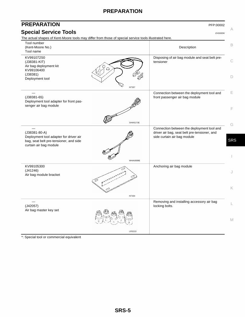
Special Service Tools EHS000IK
The actual shapes of Kent-Moore tools may differ from those of special service tools illustrated here.
*: Special tool or commercial equivalent
Tool number(Kent-Moore No.)Tool name
Description
KV991072S0(J38381-KIT)Air bag deployment kitKV99106400(J38381)Deployment tool
Disposing of air bag module and seat belt pre-tensioner
—(J38381-65)Deployment tool adapter for front pas-senger air bag module
Connection between the deployment tool and front passenger air bag module
—(J38381-80-A)Deployment tool adapter for driver air bag, seat belt pre-tensioner, and side curtain air bag module
Connection between the deployment tool and driver air bag, seat belt pre-tensioner, and side curtain air bag module
KV99105300(J41246)Air bag module bracket
Anchoring air bag module
—(J42057)Air bag master key set
Removing and installing accessory air bag locking bolts.
NT357
SHIA0173E
WHIA0089E
NT354
LRS210

SRS-6
SRS CONFIGURATION
SRS CONFIGURATION PFP:00000
Description EHS000IL
The air bags and seat belt pre-tensioners deploy if the air bag diagnosis sensor unit activates while the ignitionswitch is in the ON or START position.The air bag diagnosis sensor unit will deploy the air bags and seat belt pre-tensioners if the G sensor activatessimultaneously with the safing sensor while the ignition switch is ON.
WHIA0076E

SRS CONFIGURATION
SRS-7
C
D
E
F
G
I
J
K
L
M
A
B
SRS
SRS Component Parts Location EHS000IM
Direct-connect SRS Component Connectors EHS000LN
The following SRS components use direct-connect style harness connectors.● Driver air bag module● LH side curtain air bag module● RH side curtain air bag module● Front LH seat belt pre-tensioner● Front RH seat belt pre-tensionerAlways pull up to release black locking tab prior to removing connector from SRS component.Always push down to lock black locking tab after installing connectorto SRS component.
WHIA0077E
WHIA0103E

SRS-8
TROUBLE DIAGNOSIS
TROUBLE DIAGNOSIS PFP:00004
Trouble Diagnoses Introduction EHS000IW
CAUTION:● Do not use electrical test equipment on any circuit related to the SRS unless instructed to in this
Service Manual. SRS wiring harnesses can be identified by yellow harness connectors.● Do not attempt to repair, splice or modify the SRS wiring harness. If the harness is damaged,
replace it with a new one.● Keep ground portion clean.
DIAGNOSIS FUNCTIONThe SRS self-diagnosis results can be read by using “AIR BAG” warning lamp and/or CONSULT-II. The read-ing of these results is accomplished using one of two modes — “User mode” and “Diagnosis mode”.The User mode is exclusively prepared for the customer (driver). This mode warns the driver of a system mal-function through the operation of the “AIR BAG” warning lamp.The Diagnosis mode allows the technician to locate and inspect the malfunctioning part.The mode applications for the “AIR BAG” warning lamp and CONSULT-II are as follows:
NOTE:Seat belt pre-tensioner malfunction is indicated by “AIR BAG” warning lamp.
DIAGNOSIS MODE FOR CONSULT-II● “SELF-DIAG [CURRENT]”
A current Self-diagnosis result (also indicated by the number of warning lamp flashes in the Diagnosismode) is displayed on the CONSULT-II screen in real time. This refers to a malfunctioning part requiringrepairs.
● “SELF-DIAG [PAST]”Diagnosis results previously stored in the memory are displayed on the CONSULT-II screen. The storedresults are not erased until memory erasing is executed.
● “TROUBLE DIAG RECORD”With TROUBLE DIAG RECORD, diagnosis results previously erased by a reset operation can be dis-played on the CONSULT-II screen.
● “ECU DISCRIMINATED NO.”The diagnosis sensor unit for each vehicle model is assignedwith its own, individual classification number. This number willbe displayed on the CONSULT-II screen, as shown. Whenreplacing the diagnosis sensor unit, refer to the part number forthe compatibility. After installation, replacement with a correctunit can be checked by confirming this classification number onthe CONSULT-II screen.
User mode Diagnosis mode Display type
“AIR BAG” warning lamp X X ON-OFF operation
CONSULT-II — X Monitoring
ECU Part No. ECU Discriminated No.
28556 8Z800 (Without side curtain air bags)
F60E
98820 2Z700 (With side curtain air bags)
F610
ARS366

TROUBLE DIAGNOSIS
SRS-9
C
D
E
F
G
I
J
K
L
M
A
B
SRS
HOW TO CHANGE SELF-DIAGNOSIS MODE WITH CONSULT-IIFrom User Mode to Diagnosis ModeAfter selecting “AIR BAG” on the “SELECT SYSTEM” screen, User mode automatically changes to Diagnosismode.
From Diagnosis Mode to User ModeTo return to User mode from Diagnosis mode, touch “BACK” key of CONSULT-II until “SELECT SYSTEM”appears, Diagnosis mode automatically changes to User mode.
HOW TO CHANGE SELF-DIAGNOSIS MODE WITHOUT CONSULT-IIFrom User Mode to Diagnosis ModeDiagnosis mode activates only when a malfunction is detected, by turning ignition switch as follows:1. Turn ignition switch “ON”.2. After “AIR BAG” warning lamp lights for 7 seconds, turn ignition switch “OFF” within 1 second.3. Wait more than 3 seconds.4. Repeat steps 1 to 3 three times.5. Turn ignition switch “ON”.SRS will not enter Diagnosis mode, if no malfunction is detected.
From Diagnosis Mode to User ModeAfter a malfunction is repaired, switch the ignition “OFF” for at least one second, then back “ON”. Diagnosismode is returned to User mode.If switching Diagnosis mode to User mode is required while malfunction is being detected, by turning ignitionswitch as follows:1. Turn ignition switch “ON”.2. After “AIR BAG” warning lamp lights for 7 seconds, turn ignition switch “OFF” within 1 second.3. Wait more than 3 seconds.4. Repeat steps 1 to 3 three times.5. Turn ignition switch “ON”.
HOW TO ERASE SELF-DIAGNOSIS RESULTS With CONSULT-II
● “SELF-DIAG [CURRENT]”A current Self-diagnosis result is displayed on the CONSULT-II screen in real time.
SRS803
SRS804

SRS-10
TROUBLE DIAGNOSIS
After the malfunction is repaired completely, no malfunction is detected on “SELF-DIAG [CURRENT]”.● “SELF-DIAG [PAST]”
Return to the “SELF-DIAG [CURRENT]” CONSULT-II screen by pushing “BACK” key of CONSULT-II andselect “SELF-DIAG [CURRENT]” in SELECT DIAG MODE. Touch “ERASE” in “SELF-DIAG [CURRENT]”mode.NOTE:If the memory of the malfunction in “SELF-DIAG [PAST]” is not erased, the User mode shows thesystem malfunction by the operation of the warning lamp even if the malfunction is repaired com-pletely.
● “TROUBLE DIAG RECORD”The memory of “TROUBLE DIAG RECORD” cannot be erased.
Without CONSULT-II
After a malfunction is repaired, switch the ignition “OFF” for at least one second, then back “ON”. Diagnosismode returns to the User mode. At that time, the self-diagnostic result is cleared.
SRS701

TROUBLE DIAGNOSIS
SRS-11
C
D
E
F
G
I
J
K
L
M
A
B
SRS
How to Perform Trouble Diagnoses for Quick and Accurate Repair EHS000IX
A good understanding of the malfunction conditions can make troubleshooting faster and more accurate.In general, each customer feels differently about a malfunction. It is important to fully understand the symp-toms or conditions for a customer complaint.
INFORMATION FROM CUSTOMERWHAT..... Vehicle modelWHEN..... Date, FrequenciesWHERE..... Road conditionsHOW..... Operating conditions, Symptoms
PRELIMINARY CHECKCheck that the following parts are in good order.● Battery, refer to SC-4, "BATTERY" .● System component-to-harness connections.● Check fuses.

SRS-12
TROUBLE DIAGNOSIS
WORK FLOWNOTE:Seat belt pre-tensioner malfunction is indicated by “AIR BAG” warning lamp.
*1: SRS-11 *2: SRS-18 *3: SRS-19
*4: SRS-29 *5: SRS-22 *6: SRS-34
SRS799

TROUBLE DIAGNOSIS
SRS-13
C
D
E
F
G
I
J
K
L
M
A
B
SRS
Schematic EHS000IY
WHWA0028E

SRS-14
TROUBLE DIAGNOSIS
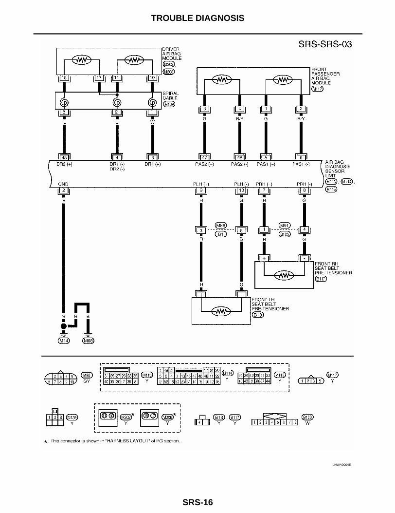
Wiring Diagram — SRS — EHS000IZ
WHWA0029E

TROUBLE DIAGNOSIS
SRS-15
C
D
E
F
G
I
J
K
L
M
A
B
SRS
LHWA0003E
SRS-16
TROUBLE DIAGNOSIS
LHWA0004E

TROUBLE DIAGNOSIS
SRS-17
C
D
E
F
G
I
J
K
L
M
A
B
SRS
LHWA0005E

SRS-18
TROUBLE DIAGNOSIS
SRS Operation Check EHS000J0
DIAGNOSTIC PROCEDURE 1Checking Air Bag Operation by Using “AIR BAG” Warning Lamp — User Mode1. After turning ignition switch from “OFF” to “ON”, “AIR BAG”
warning lamp operates.2. Compare “AIR BAG” warning lamp operation to the chart below.
SRS800
“AIR BAG” warning lamp operation — User mode — SRS condition Reference item
No malfunction is detected. No further action is necessary.
—
The system is malfunc-tioning and needs to be repaired as indicated.
Go to SRS-19, "DIAG-NOSTIC PROCEDURE 2" or SRS-29, "DIAGNOSTIC PROCEDURE 6" .
Air bag is deployed.Seat belt pre-tensioner is deployed.
Go to SRS-59, "Collision Diagnosis" .
Air bag fuse, diagnosis sensor unit or harness is malfunctioning and needs to be repaired.
Go to SRS-37, "DIAG-NOSTIC PROCEDURE 9" .
One of the following has occurred and needs to be repaired.
● Meter fuse is blown.
● “AIR BAG” warning lamp circuit has open or short.
● Diagnosis sensor unit is malfunctioning.
Go to SRS-38, "DIAG-NOSTIC PROCEDURE 10" .
MRS095A
MRS096A
MRS097A
MRS098A
TROUBLE DIAGNOSIS
SRS-19
C
D
E
F
G
I
J
K
L
M
A
B
SRS
Trouble Diagnoses with CONSULT-II EHS000J1
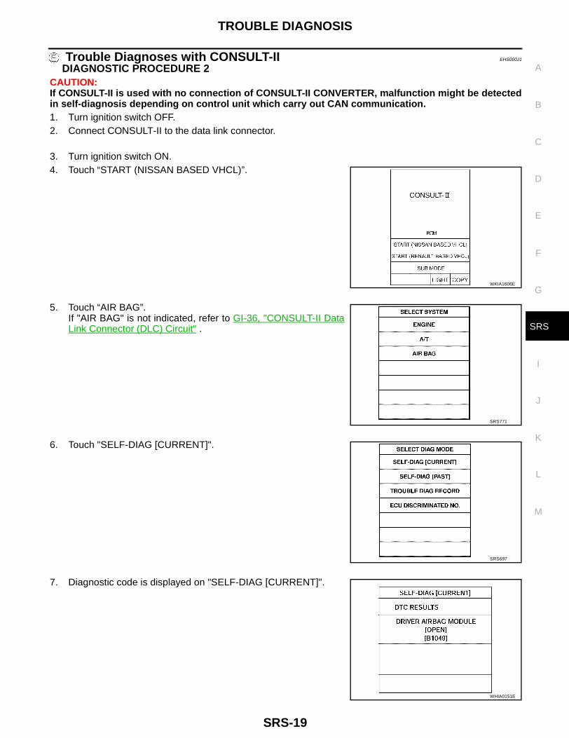
DIAGNOSTIC PROCEDURE 2CAUTION:If CONSULT-II is used with no connection of CONSULT-II CONVERTER, malfunction might be detectedin self-diagnosis depending on control unit which carry out CAN communication.1. Turn ignition switch OFF.2. Connect CONSULT-II to the data link connector.
3. Turn ignition switch ON.4. Touch “START (NISSAN BASED VHCL)”.
5. Touch “AIR BAG”.If "AIR BAG" is not indicated, refer to GI-36, "CONSULT-II DataLink Connector (DLC) Circuit" .
6. Touch "SELF-DIAG [CURRENT]".
7. Diagnostic code is displayed on "SELF-DIAG [CURRENT]".
WKIA1606E
SRS771
SRS697
WHIA0151E

SRS-20
TROUBLE DIAGNOSIS
If no malfunction is detected on "SELF-DIAG [CURRENT]" eventhough malfunction is detected in "SRS Operation Check", refer toSRS-25, "DIAGNOSTIC PROCEDURE 4 (CONTINUED FROMDIAGNOSTIC PROCEDURE 2)" , to diagnose the following cases:● Self-diagnostic result "SELF-DIAG [PAST]" (previously stored in
the memory) might not be erased after repair.● The SRS system malfunctions intermittently.
CONSULT-II Diagnostic Code Chart (“SELF-DIAG [CURRENT]”)
SRS701
Diagnostic item ExplanationRepair order “Recheck SRS at
each replacement.”
NO DTC IS DETECTED
When malfunction is indi-cated by the “AIR BAG” warning lamp in User mode
● Low battery voltage (Less than 9V) ● Go to SRS-22, "DIAGNOSTIC PROCEDURE 3" after charging battery.
● Self-diagnostic result “SELF-DIAG [PAST]” (previously stored in the mem-ory) might not be erased after repair.
● Intermittent malfunction has been detected in the past.
● Go to SRS-25, "DIAGNOSTIC PROCEDURE 4 (CONTINUED FROM DIAGNOSTIC PROCE-DURE 2)" .
● No malfunction is detected. ● Go to SRS-22, "DIAGNOSTIC PROCEDURE 3" .
DRIVER AIRBAG MODULE[OPEN][B1049] or [B1054]
● Driver air bag module circuit is open. (including the spiral cable) 1. Visually check the wiring harness connection.
2. Replace the harness if it has visi-ble damage.
3. Replace driver air bag module. (Before disposal, it must be deployed.)
4. Replace the spiral cable.
5. Replace the air bag diagnosis sensor unit.
6. Replace the related harness.
DRIVER AIRBAG MODULE[VB-SHORT][B1050] or [B1055]
● Driver air bag module circuit is shorted to a power supply circuit. (including the spiral cable)
DRIVER AIRBAG MODULE[GND-SHORT][B1051] or [B1056]
● Driver air bag module circuit is shorted to ground. (including the spiral cable)
DRIVER AIRBAG MODULE[SHORT][B1052] or [B1057]
● Driver air bag module circuit is shorted between lines.
ASSIST A/B MODULE[OPEN][B1065] or [B1070]
● Passenger air bag module circuit is open.1. Visually check the wiring harness
connection.
2. Replace the harness if it has visi-ble damage.
3. Replace passenger air bag mod-ule. (Before disposal, it must be deployed.)
4. Replace the air bag diagnosis sensor unit.
5. Replace the related harness.
ASSIST A/B MODULE[VB-SHORT][B1066] or [B1071]
● Passenger air bag module circuit is shorted to a power supply cir-cuit.
ASSIST A/B MODULE[GND-SHORT][B1067] or [B1072]
● Passenger air bag module circuit is shorted to ground.
ASSIST A/B MODULE[SHORT][B1068] or [B1073]
● Passenger air bag module circuit is shorted between lines.

TROUBLE DIAGNOSIS
SRS-21
C
D
E
F
G
I
J
K
L
M
A
B
SRS
PRE-TEN FRONT LH[OPEN][B1086]
● Front LH seat belt pre-tensioner circuit is open. 1. Visually check the wiring harness connections.
2. Replace the harness if it has visi-ble damage.
3. Replace driver seat belt.(Before disposing, the front LH seat belt pre-tensioner must be activated.)
4. Replace the air bag diagnosis sensor unit.
5. Replace the related harness.
PRE-TEN FRONT LH[VB-SHORT][B1087]
● Front LH seat belt pre-tensioner circuit is shorted to a power supply circuit.
PRE-TEN FRONT LH[GND-SHORT][B1088]
● Front LH seat belt pre-tensioner circuit is shorted to ground.
PRE-TEN FRONT LH[SHORT][B1089]
● Front LH seat belt pre-tensioner circuit is shorted between lines.
PRE-TEN FRONT RH[OPEN][B1081]
● Front RH seat belt pre-tensioner circuit is open. 1. Visually check the wiring harness connections.
2. Replace the harness if it has visi-ble damage.
3. Replace passenger seat belt.(Before disposing, the front RH seat belt pre-tensioner must be activated.)
4. Replace the air bag diagnosis sensor unit.
5. Replace the related harness.
PRE-TEN FRONT RH[VB-SHORT][B1082]
● Front RH seat belt pre-tensioner circuit is shorted to a power supply circuit.
PRE-TEN FRONT RH[GND-SHORT][B1083]
● The circuit for front RH seat belt pre-tensioner is shorted to ground.
PRE-TEN FRONT RH[SHORT][B1084]
● Front RH seat belt pre-tensioner circuit is shorted between lines.
CRASH ZONE SEN[UNIT FAIL][B1033] or [B1034]CRASH ZONE SEN[COMM FAIL][B1035]
● Crash zone sensor 1. Visually check the wiring harness connection.
2. Replace the harness if it has visi-ble damage.
3. Replace the crash zone sensor.
4. Replace the diagnosis sensor unit.
5. Replace the related harness.
CURTAIN MODULE LH[OPEN][B1150]
● LH side curtain air bag module circuit is open.1. Visually check the wiring harness
connection.
2. Replace the harness if it has visi-ble damage.
3. Replace LH side curtain air bag module.(Before disposal, it must be deployed.)
4. Replace the diagnosis sensor unit.
5. Replace the related harness.
CURTAIN MODULE LH[VB-SHORT][B1151]
● LH side curtain air bag module circuit is shorted to a power supply circuits.
CURTAIN MODULE LH[GND-SHORT][B1152]
● LH side curtain air bag module circuit is shorted to ground.
CURTAIN MODULE LH[SHORT][B1153]
● LH side curtain air bag module circuit is shorted between lines.
SATELLITE SENS RH[UNIT FAIL][B1113] or [B1114]SATELLITE SENS RH[COMM FAIL][B1115]
● RH side air bag (satellite) sensor. 1. Visually check the wiring harness connection.
2. Replace the harness if it has visi-ble damage.
3. Replace the RH side air bag (sat-ellite) sensor.
4. Replace the diagnosis sensor unit.
5. Replace the related harness.
Diagnostic item ExplanationRepair order “Recheck SRS at
each replacement.”

SRS-22
TROUBLE DIAGNOSIS
* Follow the procedures in numerical order when repairing malfunctioning parts. Confirm whether malfunction is eliminatedusing the air bag warning lamp or CONSULT-II each time repair is finished. If malfunction is still observed, proceed to the nextstep. When malfunction is eliminated, further repair work is not required.
DIAGNOSTIC PROCEDURE 3CAUTION:If CONSULT-II is used with no connection of CONSULT-II CONVERTER, malfunction might be detectedin self-diagnosis depending on control unit which carry out CAN communication.1. After repairing SRS, connect both battery cables.2. Connect CONSULT-II to data link connector.3. Turn ignition switch ON.
SATELLITE SENS LH[UNIT FAIL][B1118] or [B1119]SATELLITE SENS LH[COMM FAIL][B1120]
● LH side air bag (satellite) sensor. 1. Visually check the wiring harness connection.
2. Replace the harness if it has visi-ble damage.
3. Replace the LH side air bag (sat-ellite) sensor.
4. Replace the diagnosis sensor unit.
5. Replace the related harness.
CURTAIN MODULE RH[OPEN][B1145]
● RH side curtain air bag module circuit is open. 1. Visually check the wiring harness connection.
2. Replace the harness if it has visi-ble damage.
3. Replace RH side curtain air bag module.(Before disposal, it must be deployed.)
4. Replace the diagnosis sensor unit.
5. Replace the related harness.
CURTAIN MODULE RH[VB-SHORT][B1146]
● RH side curtain air bag module circuit is shorted to a power supply circuit.
CURTAIN MODULE RH[GND-SHORT][B1147]
● RH side curtain air bag module circuit is shorted to ground.
CURTAIN MODULE RH[SHORT][B1148]
● RH side curtain air bag module circuit is shorted between lines.
CONTROL UNIT[B1XXX]
● Air bag diagnosis sensor unit is malfunctioning. 1. Visually check the wiring harness connection.
2. Replace the air bag diagnosis sensor unit.
Diagnostic item ExplanationRepair order “Recheck SRS at
each replacement.”
LEC104A

TROUBLE DIAGNOSIS
SRS-23
C
D
E
F
G
I
J
K
L
M
A
B
SRS
4. Touch “START (NISSAN BASED VHCL)”.
5. Touch “AIR BAG”.If "AIR BAG" is not indicated, refer to GI-36, "CONSULT-II DataLink Connector (DLC) Circuit" .
6. Touch “SELF-DIAG [CURRENT]”.
7. If no malfunction is detected on “SELF-DIAG [CURRENT]”,repair of SRS is completed. Go to step 8.If any malfunction is detected on “SELF-DIAG [CURRENT]”, themalfunctioning part is not repaired completely or another mal-functioning part is detected. Go to SRS-19, "DIAGNOSTICPROCEDURE 2" , and repair malfunctioning part completely.
WKIA1606E
SRS771
SRS697
SRS701

SRS-24
TROUBLE DIAGNOSIS
8. Touch “ERASE”.NOTE:Touch “ERASE” to clear the memory of the malfunction(“SELF-DIAG [PAST]”).If the memory of the malfunction in “SELF-DIAG [PAST]” is noterased, the User mode shows the system malfunction by theoperation of the warning lamp even if the malfunction is repairedcompletely.
9. Touch “BACK” key of CONSULT-II to “SELECT DIAG MODE”screen. Touch “SELF-DIAG [PAST]”.
10. Check that no malfunction is detected on “SELF-DIAG [PAST]”.11. Touch “BACK” key of CONSULT-II until “SELECT SYSTEM”
appears in order to return to User mode from Diagnosis mode.12. Turn ignition switch OFF then turn off and disconnect CON-
SULT-II.13. Go to SRS-18, "Checking Air Bag Operation by Using “AIR
BAG” Warning Lamp — User Mode" .
WHIA0152E
SRS697
SRS702

TROUBLE DIAGNOSIS
SRS-25
C
D
E
F
G
I
J
K
L
M
A
B
SRS
DIAGNOSTIC PROCEDURE 4 (CONTINUED FROM DIAGNOSTIC PROCEDURE 2)Inspecting SRS malfunctioning record
1. CONSIDER POSSIBILITY OF NOT ERASING SELF-DIAGNOSTIC RESULT AFTER REPAIRING
Is it the first time for maintenance of SRS?Yes or NoYes >> Go to SRS-25, "DIAGNOSTIC PROCEDURE 5" .No >> Self-diagnostic result “SELF-DIAG [PAST]” (previously stored in the memory) might not be erased
after repair. Go to SRS-22, "DIAGNOSTIC PROCEDURE 3" .
DIAGNOSTIC PROCEDURE 5CAUTION:If CONSULT-II is used with no connection of CONSULT-II CONVERTER, malfunction might be detectedin self-diagnosis depending on control unit which carry out CAN communication.1. Turn ignition switch OFF.2. Connect CONSULT-II to data link connector.
3. Touch “START (NISSAN BASED VHCL)”.4. Turn ignition switch ON.
5. Touch “AIR BAG”.If "AIR BAG" is not indicated, refer to GI-36, "CONSULT-II DataLink Connector (DLC) Circuit" .
LEC104A
WKIA1606E
SRS771
SRS-26
TROUBLE DIAGNOSIS
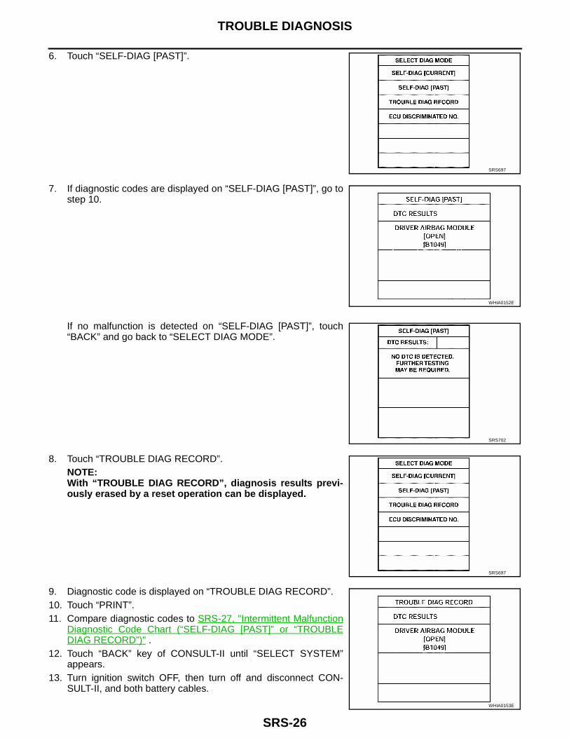
6. Touch “SELF-DIAG [PAST]”.
7. If diagnostic codes are displayed on “SELF-DIAG [PAST]”, go tostep 10.
If no malfunction is detected on “SELF-DIAG [PAST]”, touch“BACK” and go back to “SELECT DIAG MODE”.
8. Touch “TROUBLE DIAG RECORD”.NOTE:With “TROUBLE DIAG RECORD”, diagnosis results previ-ously erased by a reset operation can be displayed.
9. Diagnostic code is displayed on “TROUBLE DIAG RECORD”.10. Touch “PRINT”.11. Compare diagnostic codes to SRS-27, "Intermittent Malfunction
Diagnostic Code Chart (“SELF-DIAG [PAST]” or “TROUBLEDIAG RECORD”)" .
12. Touch “BACK” key of CONSULT-II until “SELECT SYSTEM”appears.
13. Turn ignition switch OFF, then turn off and disconnect CON-SULT-II, and both battery cables.
SRS697
WHIA0152E
SRS702
SRS697
WHIA0153E

TROUBLE DIAGNOSIS
SRS-27
C
D
E
F
G
I
J
K
L
M
A
B
SRS
14. Repair the system as outlined by the “Repair order” in “Intermittent Malfunction Diagnostic Code Chart”,that corresponds to the self-diagnostic result. For replacement procedure of component parts, refer to theRemoval and Installation procedure for the appropriate component.
15. Go to SRS-22, "DIAGNOSTIC PROCEDURE 3" , for final checking.
Intermittent Malfunction Diagnostic Code Chart (“SELF-DIAG [PAST]” or “TROUBLE DIAG RECORD”)
Diagnostic item ExplanationRepair order “Recheck SRS at
each replacement.”
NO DTC IS DETECTED
When malfunction is indi-cated by the “AIR BAG” warning lamp in User mode
● Low battery voltage (Less than 9V) ● Go to SRS-22, "DIAGNOSTIC PROCEDURE 3" after charging battery.
● Self-diagnostic result “SELF-DIAG [PAST]” (previously stored in the mem-ory) might not be erased after repair.
● Intermittent malfunction has been detected in the past.
● Go to SRS-25, "DIAGNOSTIC PROCEDURE 4 (CONTINUED FROM DIAGNOSTIC PROCE-DURE 2)" .
● No malfunction is detected. ● Go to SRS-22, "DIAGNOSTIC PROCEDURE 3" .
DRIVER AIRBAG MODULE[OPEN][B1049] or [B1054]
● Driver air bag module circuit is open. (including the spiral cable) 1. Visually check the wiring harness connection.
2. Replace the harness if it has visi-ble damage.
3. Replace driver air bag module. (Before disposal, it must be deployed.)
4. Replace the spiral cable.
5. Replace the air bag diagnosis sensor unit.
6. Replace the related harness.
DRIVER AIRBAG MODULE[VB-SHORT][B1050] or [B1055]
● Driver air bag module circuit is shorted to a power supply circuit. (including the spiral cable)
DRIVER AIRBAG MODULE[GND-SHORT][B1051] or [B1056]
● Driver air bag module circuit is shorted to ground. (including the spiral cable)
DRIVER AIRBAG MODULE[SHORT][B1052] or [B1057]
● Driver air bag module circuit is shorted between lines.
ASSIST A/B MODULE[OPEN][B1065] or [B1070]
● Passenger air bag module circuit is open.1. Visually check the wiring harness
connection.
2. Replace the harness if it has visi-ble damage.
3. Replace passenger air bag mod-ule. (Before disposal, it must be deployed.)
4. Replace the air bag diagnosis sensor unit.
5. Replace the related harness.
ASSIST A/B MODULE[VB-SHORT][B1066] or [B1071]
● Passenger air bag module circuit is shorted to a power supply cir-cuit.
ASSIST A/B MODULE[GND-SHORT][B1067] or [B1072]
● Passenger air bag module circuit is shorted to ground.
ASSIST A/B MODULE[SHORT][B1068] or [B1073]
● Passenger air bag module circuit is shorted between lines.

SRS-28
TROUBLE DIAGNOSIS
PRE-TEN FRONT LH[OPEN][B1086]
● Front LH seat belt pre-tensioner circuit is open. 1. Visually check the wiring harness connections.
2. Replace the harness if it has visi-ble damage.
3. Replace driver seat belt.(Before disposing, the front LH seat belt pre-tensioner must be activated.)
4. Replace the air bag diagnosis sensor unit.
5. Replace the related harness.
PRE-TEN FRONT LH[VB-SHORT][B1087]
● Front LH seat belt pre-tensioner circuit is shorted to a power supply circuit.
PRE-TEN FRONT LH[GND-SHORT][B1088]
● Front LH seat belt pre-tensioner circuit is shorted to ground.
PRE-TEN FRONT LH[SHORT][B1089]
● Front LH seat belt pre-tensioner circuit is shorted between lines.
PRE-TEN FRONT RH[OPEN][B1081]
● Front RH seat belt pre-tensioner circuit is open. 1. Visually check the wiring harness connections.
2. Replace the harness if it has visi-ble damage.
3. Replace passenger seat belt.(Before disposing, the front RH seat belt pre-tensioner must be activated.)
4. Replace the air bag diagnosis sensor unit.
5. Replace the related harness.
PRE-TEN FRONT RH[VB-SHORT][B1082]
● Front RH seat belt pre-tensioner circuit is shorted to a power supply circuit.
PRE-TEN FRONT RH[GND-SHORT][B1083]
● The circuit for front RH seat belt pre-tensioner is shorted to ground.
PRE-TEN FRONT RH[SHORT][B1084]
● Front RH seat belt pre-tensioner circuit is shorted between lines.
CRASH ZONE SEN[UNIT FAIL][B1033] or [B1034]CRASH ZONE SEN[COMM FAIL][B1035]
● Crash zone sensor 1. Visually check the wiring harness connection.
2. Replace the harness if it has visi-ble damage.
3. Replace the crash zone sensor.
4. Replace the diagnosis sensor unit.
5. Replace the related harness.
CURTAIN MODULE LH[OPEN][B1150]
● LH side curtain air bag module circuit is open.1. Visually check the wiring harness
connection.
2. Replace the harness if it has visi-ble damage.
3. Replace LH side curtain air bag module.(Before disposal, it must be deployed.)
4. Replace the diagnosis sensor unit.
5. Replace the related harness.
CURTAIN MODULE LH[VB-SHORT][B1151]
● LH side curtain air bag module circuit is shorted to a power supply circuits.
CURTAIN MODULE LH[GND-SHORT][B1152]
● LH side curtain air bag module circuit is shorted to ground.
CURTAIN MODULE LH[SHORT][B1153]
● LH side curtain air bag module circuit is shorted between lines.
SATELLITE SENS RH[UNIT FAIL][B1113] or [B1114]SATELLITE SENS RH[COMM FAIL][B1115]
● RH side air bag (satellite) sensor. 1. Visually check the wiring harness connection.
2. Replace the harness if it has visi-ble damage.
3. Replace the RH side air bag (sat-ellite) sensor.
4. Replace the diagnosis sensor unit.
5. Replace the related harness.
Diagnostic item ExplanationRepair order “Recheck SRS at
each replacement.”

TROUBLE DIAGNOSIS
SRS-29
C
D
E
F
G
I
J
K
L
M
A
B
SRS
* Follow the procedures in numerical order when repairing malfunctioning parts. Confirm whether malfunction is eliminatedusing the air bag warning lamp or CONSULT-II each time repair is finished. If malfunction is still observed, proceed to the nextstep. When malfunction is eliminated, further repair work is not required.
Trouble Diagnoses without CONSULT-II EHS000J2
DIAGNOSTIC PROCEDURE 6Inspecting SRS malfunctioning parts by using “AIR BAG” warn-ing lamp — Diagnosis modeNOTE:SRS will not enter Diagnosis mode if no malfunction is detectedin User mode.1. Turn ignition switch “ON”.2. After “AIR BAG” warning lamp lights for 7 seconds, turn ignition
switch “OFF” within 1 second.3. Wait more than 3 seconds.4. Repeat steps 1 to 3 three times.5. Turn ignition switch “ON”.
SRS is now in Diagnosis mode.6. “AIR BAG” warning lamp operates in Diagnosis mode as follows:NOTE:If SRS does not enter Diagnosis mode even though malfunction is detected in User mode, check the batteryvoltage.If the battery voltage is less than 9V, charge the battery. Then refer to SRS-34, "DIAGNOSTIC PROCEDURE7" .If the battery voltage is OK, replace the air bag diagnosis sensor unit.
SATELLITE SENS LH[UNIT FAIL][B1118] or [B1119]SATELLITE SENS LH[COMM FAIL][B1120]
● LH side air bag (satellite) sensor. 1. Visually check the wiring harness connection.
2. Replace the harness if it has visi-ble damage.
3. Replace the LH side air bag (sat-ellite) sensor.
4. Replace the diagnosis sensor unit.
5. Replace the related harness.
CURTAIN MODULE RH[OPEN][B1145]
● RH side curtain air bag module circuit is open. 1. Visually check the wiring harness connection.
2. Replace the harness if it has visi-ble damage.
3. Replace RH side curtain air bag module.(Before disposal, it must be deployed.)
4. Replace the diagnosis sensor unit.
5. Replace the related harness.
CURTAIN MODULE RH[VB-SHORT][B1146]
● RH side curtain air bag module circuit is shorted to a power supply circuit.
CURTAIN MODULE RH[GND-SHORT][B1147]
● RH side curtain air bag module circuit is shorted to ground.
CURTAIN MODULE RH[SHORT][B1148]
● RH side curtain air bag module circuit is shorted between lines.
CONTROL UNIT[B1XXX]
● Air bag diagnosis sensor unit is malfunctioning. 1. Visually check the wiring harness connection.
2. Replace the air bag diagnosis sensor unit.
Diagnostic item ExplanationRepair order “Recheck SRS at
each replacement.”
SRS800

SRS-30
TROUBLE DIAGNOSIS
7. Malfunctioning part is indicated by the number of flashes (part d ). Compare the number of flashes to “AirBag Warning Lamp Flash Code Chart”. Refer to SRS-31, "Air Bag Warning Lamp Flash Code Chart (Diag-nosis mode)" , and locate malfunctioning part.
8. Turn ignition switch “OFF”, and disconnect both battery cables.9. Repair the system as outlined by the “Repair order” in “Warning Lamp Flash Code Chart” that corre-
sponds to the flash code. For replacement procedure of component parts, refer to SRS-39, "Removal andInstallation" .
10. After repairing the system, refer to SRS-34, "DIAGNOSTIC PROCEDURE 7" .
No. “AIR BAG” warning lamp flash pattern — Diagnosis mode — SRS condition
1
a through b are repeated. ● Diagnosis results (pre-viously stored in the mem-ory) might not be erased after repair.
● Intermittent malfunction has been detected in the past.
Go to SRS-36, "DIAG-NOSTIC PROCE-DURE 8 (CONTIN-UED FROM DIAGNOS-TIC PROCE-DURE 6)" .
2
a through d are repeated.b — Driver and passenger air bag and seat belt pre-tensioner marker (For identifying driver air bag, passenger air bag and/or seat belt pre-tensioners mal-functioning)d — Indicates malfunctioning part. The number of flash varies with malfunctioning part (0.5 sec. ON and 0.5 sec. OFF is counted as one flash.)
The system is malfunction-ing and needs to be repaired.
SRS333
SRS341

TROUBLE DIAGNOSIS
SRS-31
C
D
E
F
G
I
J
K
L
M
A
B
SRS
Air Bag Warning Lamp Flash Code Chart (Diagnosis mode)
● Diagnosis results (pre-viously stored in the memory) might not be erased after repair.
● Intermittent malfunc-tion has been detected in the past.
Flash pattern
a through b are repeated.
Repair order
● Go toSRS-36, "DIAGNOSTIC PROCEDURE 8 (CONTINUED FROM DIAGNOSTIC PROCEDURE 6)" .
The front RH seat belt pre-tensioner circuit is malfunctioning.(d : 1 flash)
Flash pattern
a through d are repeated.d — One flash indicates malfunctioning passen-ger pre-tensioner circuit.
Repair order (Recheck SRS at each replacement. Refer to SRS-18, "SRS Operation Check" .)
1. Visually check the wiring harness connections.
2. Replace the harness if it has visible damage.
3. Replace front RH seat belt pre-tensioner.(Before disposing the front RH seat belt pre-tensioner, it must be deployed.)
4. Replace the air bag diagnosis sensor unit.
5. Replace the related harness.
The driver air bag mod-ule circuit is malfunction-ing.(d : 2 flashes)
Flash pattern
a through d are repeated.d — Two flashes indi-cate malfunctioning driver air bag module cir-cuit.
Repair order (Recheck SRS at each replacement. Refer to SRS-18, "SRS Operation Check" .)
1. Visually check the wiring harness connection.
2. Replace the harness if it has visible damage.
3. Replace the spiral cable.
4. Replace driver air bag module.(Before disposal, it must be deployed.)
5. Replace the air bag diagnosis sensor unit.
6. Replace the related harness.
SRS333
SRS801
SRS334

SRS-32
TROUBLE DIAGNOSIS
The front LH seat belt pre-tensioner circuit is malfunctioning.(d : 3 flashes)
Flash pattern
a through d are repeated.d — Three flashes indi-cate malfunctioning driver pre-tensioner cir-cuit.
Repair order (Recheck SRS at each replacement. Refer to SRS-18, "SRS Operation Check" .).
1. Visually check the wiring harness connections.
2. Replace the harness if it has visible damage.
3. Replace front LH seat belt pre-tensioner.(Before disposing the front LH seat belt pre-tensioner, it must be deployed.)
4. Replace the air bag diagnosis sensor unit.
5. Replace the related harness.
The crash zone sensor circuit is malfunctioning.(d : 6 flashes)
Flash pattern
a through d are repeated.d — Six flashes indicate malfunctioning crash zone sensor circuit.
Repair order (“Recheck SRS at each replacement”).
1. Visually check the wiring harness connections.
2. Replace the harness if it has visible damage.
3. Replace crash zone sensor.
4. Replace the diagnosis sensor unit.
5. Replace the related harness.
RH side curtain air bag module
Flash pattern
a through f are repeated.f — five flashes indi-cate malfunctioning RH side curtain air bag mod-ule circuit.
Repair order (“Recheck SRS at each replacement”).
1. Visually check the wiring harness connections.
2. Replace the harness if it has visible damage.
3. Replace RH side curtain air bag module (Before disposal, it must be deployed).
4. Replace the diagnosis sensor unit.
5. Replace the related harness.
SRS802
SRS911
WHIA0074E

TROUBLE DIAGNOSIS
SRS-33
C
D
E
F
G
I
J
K
L
M
A
B
SRS
* Follow the procedures in numerical order when repairing malfunctioning parts. Confirm whether malfunction is eliminatedusing the air bag warning lamp or CONSULT-II each time repair is finished. If malfunction is still observed, proceed to the nextstep. When malfunction is eliminated, further repair work is not required.
RH side curtain air bag module
Flash pattern
a through f are repeated.f — six flashes indicate malfunctioning LH side curtain air bag module circuit.
Repair order (“Recheck SRS at each replacement”).
1. Visually check the wiring harness connections.
2. Replace the harness if it has visible damage.
3. Replace RH side curtain air bag module (Before disposal, it must be deployed).
4. Replace the diagnosis sensor unit.
5. Replace the related harness.
The air bag diagnosis sensor unit is malfunc-tioning.(d : 7 flashes)
Flash pattern
a through d are repeated.d — Seven flashes indi-cate malfunctioning air bag diagnosis sensor unit.
Repair order (Recheck SRS at each replacement. Refer to SRS-18, "SRS Operation Check" .)
1. Visually check the wiring harness connections.
2. Replace the harness if it has visible damage.
3. Replace the air bag diagnosis sensor unit.
4. Replace the related harness.
The passenger air bag module circuit is mal-functioning.(d : 8 flashes)
Flash pattern
a through d are repeated.d — Eight flashes indi-cate malfunctioning pas-senger air bag module circuit.
Repair order (Recheck SRS at each replacement. Refer to SRS-18, "SRS Operation Check" .)
1. Visually check the wiring harness connection.
2. Replace the harness if it has visible damage.
3. Replace passenger air bag module.(Before disposal, it must be deployed.)
4. Replace the air bag diagnosis sensor unit.
5. Replace the related harness.
WHIA0075E
SRS335
SRS336

SRS-34
TROUBLE DIAGNOSIS
DIAGNOSTIC PROCEDURE 7Final checking after repairing SRS by using “AIR BAG” warninglamp — Diagnosis mode and User mode1. After repairing SRS connect both battery cables.2. Turn ignition switch from “OFF” to “ON”.3. “AIR BAG” warning lamp operates in Diagnosis mode as fol-
lows:
NOTE:When diagnosis sensor unit is replaced with new one, “AIR BAG” warning lamp will operate in User mode.Checking “AIR BAG” warning lamp operation in Diagnosis mode is not required. Go to step 5.4. If “AIR BAG” warning lamp operates as shown in No. 1 in chart above, turn ignition switch “OFF” to reset
from Diagnosis mode to User mode and to erase the memory of the malfunction. Then go to step 6.If “AIR BAG” warning lamp operates as shown in No. 2 or No. 3 in chart above, the malfunctioning part isnot repaired completely, or another malfunctioning part is detected. Refer to SRS-29, "DIAGNOSTICPROCEDURE 6" , and repair malfunctioning part completely.
5. Turn ignition switch “ON”. “AIR BAG” warning lamp operates in User mode. Compare “AIR BAG” warninglamp operation to the chart below.
NOTE:If switching Diagnosis mode to User mode is required while malfunction is being detected, by turning ignitionswitch as follows:1. Turn ignition switch “ON”.2. After “AIR BAG” warning lamp lights for 7 seconds, turn ignition switch “OFF” within 1 second.3. Wait more than 3 seconds.4. Repeat steps 1 to 3 three times.5. Turn ignition switch “ON”.SRS is now in User mode.
SRS800
No.
“AIR BAG” warning lamp flash pattern — Diagnosis mode — SRS condition
1
a through b are repeated. No malfunc-tion is detected or repair is com-pleted.No further action is nec-essary.
2
a through d are repeated.b — Driver and passenger air bag and seat belt pre-tensioner marker (For identifying driver air bag, passenger air bag and/or seat belt pre-tensioners mal-functioning)d — Indicates malfunctioning part. The number of flashes var-ies with malfunctioning part (0.5 sec. ON and 0.5 sec. OFF is counted as one flash.)
The system is malfunction-ing and needs to be repaired.
SRS333
SRS341

TROUBLE DIAGNOSIS
SRS-35
C
D
E
F
G
I
J
K
L
M
A
B
SRS
“AIR BAG” warning lamp operation — User mode — SRS condition Reference item
No malfunction is detected.No further action is neces-sary. —
The system is malfunc-tioning and needs to be repaired as indicated.
Go to SRS-29, "DIAG-NOSTIC PROCEDURE 6" .
Air bag is deployed.Seat belt pre-tensioner is deployed.
Go toSRS-59, "Collision Diagnosis" .
Air bag fuse, air bag diag-nosis sensor unit or har-ness is malfunctioning and needs to be repaired.
Go to SRS-37, "DIAG-NOSTIC PROCEDURE 9" .
One of the following has occurred and needs to be repaired.
● Meter fuse is blown.
● “AIR BAG” warning lamp circuit has open or short.
● Air bag diagnosis sen-sor unit is malfunction-ing.
Go to SRS-38, "DIAG-NOSTIC PROCEDURE 10" .
MRS095A
MRS096A
MRS097A
MRS098A

SRS-36
TROUBLE DIAGNOSIS
DIAGNOSTIC PROCEDURE 8 (CONTINUED FROM DIAGNOSTIC PROCEDURE 6)Inspecting SRS malfunctioning record
1. CONSIDER POSSIBILITY OF NOT ERASING SELF-DIAGNOSTIC RESULT AFTER REPAIRING
Is it the first time for maintenance of SRS?Yes or NoYes >> Go to SRS-25, "DIAGNOSTIC PROCEDURE 5" . (Further inspection cannot be performed with-
out CONSULT-II.)No >> Diagnosis results (previously stored in the memory) might not be erased after repair. Go to SRS-
34, "DIAGNOSTIC PROCEDURE 7" .

TROUBLE DIAGNOSIS
SRS-37
C
D
E
F
G
I
J
K
L
M
A
B
SRS
Trouble Diagnoses: “AIR BAG” Warning Lamp Does Not Turn Off EHS000J3
DIAGNOSTIC PROCEDURE 9
1. SEE THE DEPLOYMENT OF AIR BAG MODULE
Is air bag module deployed?Yes or NoYes >> Refer to SRS-59, "Collision Diagnosis" .No >> GO TO 2.
2. CHECK AIR BAG FUSE
Is SRS “AIR BAG” fuse OK?OK or NGOK >> GO TO 4.NG >> GO TO 3.
3. CHECK AIR BAG FUSE AGAIN
Replace “AIR BAG” fuse and turn ignition switch ON.Does “AIR BAG” fuse blow again?Yes >> Repair main harness.No >> INSPECTION END
4. CHECK DIAGNOSIS SENSOR UNIT
Connect CONSULT-II and touch “START”.● Is “AIR BAG” displayed on CONSULT-II?Yes or NoYes >> GO TO 5.No >> Visually check the wiring harness connection of air bag
diagnosis sensor unit. If the harness connection checkresult is OK, replace air bag diagnosis sensor unit.
5. CHECK HARNESS CONNECTION
Is harness connection between warning lamp and air bag diagnosis sensor unit OK?OK or NGOK >> Replace air bag diagnosis sensor unit.NG >> Connect “AIR BAG” warning lamp and air bag diagnosis sensor unit connector properly. If “AIR
BAG” warning lamp still does not go off, replace harness.
WRS264
SRS771

SRS-38
TROUBLE DIAGNOSIS
Trouble Diagnoses: “AIR BAG” Warning Lamp Does Not Turn On EHS000J4
DIAGNOSTIC PROCEDURE 10
1. CHECK “METER” FUSE
Is meter fuse OK?OK or NGOK >> GO TO 3.NG >> GO TO 2.
2. CHECK “METER” FUSE AGAIN
Replace meter fuse and turn ignition switch ON.Does meter fuse blow again?Yes >> Repair main harness.No >> INSPECTION END
3. CHECK HARNESS CONNECTION BETWEEN AIR BAG DIAGNOSIS SENSOR UNIT AND “AIR BAG” WARNING LAMP
Disconnect air bag diagnosis sensor unit connector and turn ignition switch “ON”.● Does “AIR BAG” warning lamp turn on?Yes or NoYes >> Replace air bag diagnosis sensor unit.No >> Check the ground circuit of “AIR BAG” warning lamp. If ground circuit is OK, replace combination
meter.
ARS350

DIAGNOSIS SENSOR UNIT
SRS-39
C
D
E
F
G
I
J
K
L
M
A
B
SRS
DIAGNOSIS SENSOR UNIT PFP:28556
Removal and Installation EHS000IN
CAUTION:● Before servicing SRS, turn the ignition switch off, disconnect both battery cables and wait for at
least 3 minutes.● The special bolts are coated with bonding agent while the other bolt is for ground. Do not reuse
bolts after removal; replace with new ones.● Check air bag diagnosis sensor unit for proper installation.● Check air bag diagnosis sensor unit to ensure it is free of deformities, dents, cracks and rust. If
there are any visible signs of damage, replace it with a new one.● Check air bag diagnosis sensor unit brackets to ensure they are free of deformities or rust.● Replace air bag diagnosis sensor unit if it has been dropped or has sustained an impact.1. Disconnect driver and passenger air bag module connectors
and seat belt pre-tensioner connectors.2. Remove console box. Refer to IP-10, "INSTRUMENT PANEL
ASSEMBLY" .3. Disconnect air bag diagnosis sensor unit connector.4. Remove ground bolt and also remove hex head bolts from air
bag diagnosis sensor unit.Then remove the air bag diagnosis sensor unit.
NOTE:● To install, reverse the removal procedure and tighten new
bolts in the sequence indicated in the illustration.● After replacement, perform self-diagnosis for SRS. Refer to SRS-18, "SRS Operation Check" .CAUTION:Air bag diagnosis sensor unit must always be installed with forward mark “⇐ ” pointing toward thefront of the vehicle for proper operation. Also check air bag diagnosis sensor unit for deformities,dents, cracks and rust before installation and replace as required.
WRS228

SRS-40
CRASH ZONE SENSOR
CRASH ZONE SENSOR PFP:98531
Removal and Installation EHS000IO
CAUTION:● Before servicing SRS, turn the ignition switch off, disconnect both battery cables and wait at least
3 minutes.● Check crash zone sensor for proper installation.● Check crash zone sensor to ensure it is free of deformities, dents, cracks or rust. If it shows any
visible signs of damage, replace it with new one.● After replacement of crash zone sensor, check SRS function and perform self-diagnosis for SRS.
Refer to SRS-18, "SRS Operation Check"● Do not attempt to disassemble crash zone sensor.● Replace crash zone sensor if it has been dropped or sustained an impact.1. Disconnect crash zone sensor.2. Remove nuts from crash zone sensor and bracket.
Then remove bracket and crash zone sensor from radiator sup-port.
NOTE:● To install, reverse the removal procedure sequence.
LRS263
SIDE AIR BAG (SATELLITE) SENSOR
SRS-41
C
D
E
F
G
I
J
K
L
M
A
B
SRS
SIDE AIR BAG (SATELLITE) SENSOR PFP:98830
Removal and Installation EHS000LV
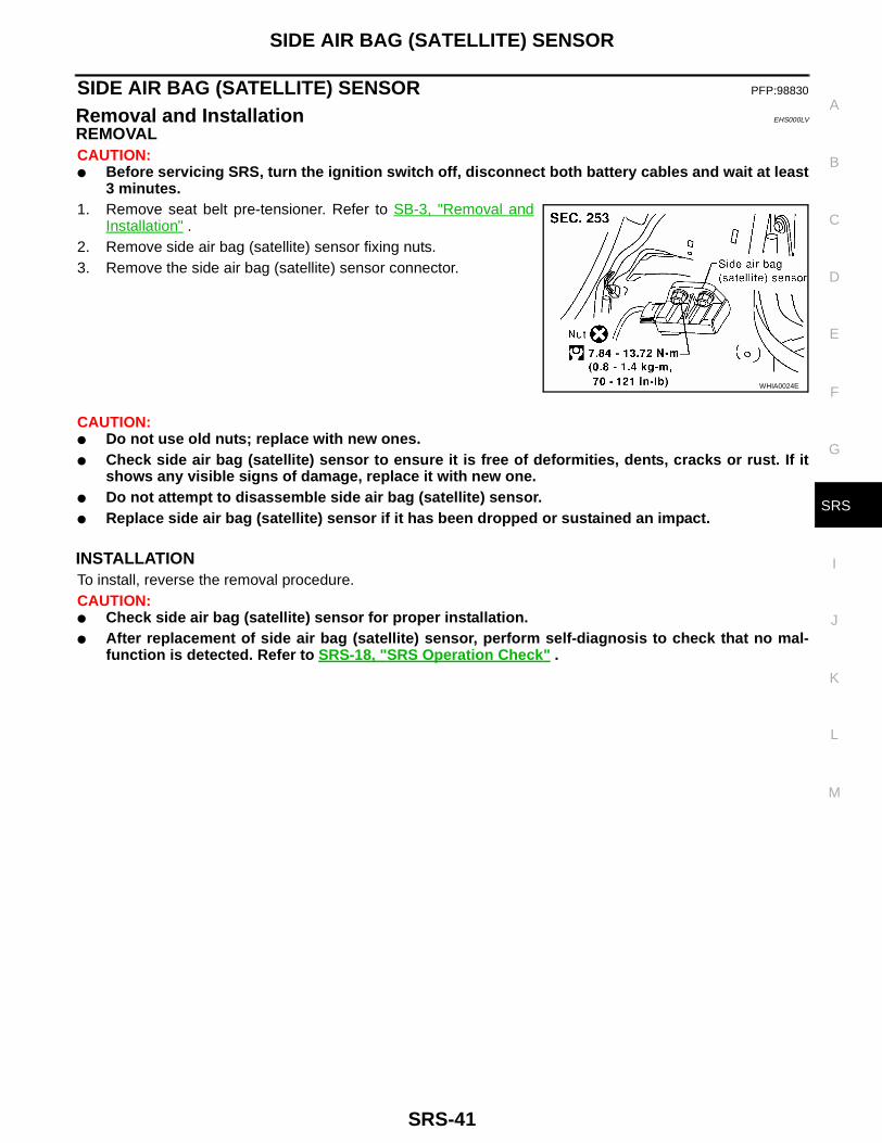
REMOVALCAUTION:● Before servicing SRS, turn the ignition switch off, disconnect both battery cables and wait at least
3 minutes.1. Remove seat belt pre-tensioner. Refer to SB-3, "Removal and
Installation" .2. Remove side air bag (satellite) sensor fixing nuts.3. Remove the side air bag (satellite) sensor connector.
CAUTION:● Do not use old nuts; replace with new ones.● Check side air bag (satellite) sensor to ensure it is free of deformities, dents, cracks or rust. If it
shows any visible signs of damage, replace it with new one.● Do not attempt to disassemble side air bag (satellite) sensor.● Replace side air bag (satellite) sensor if it has been dropped or sustained an impact.
INSTALLATIONTo install, reverse the removal procedure.CAUTION:● Check side air bag (satellite) sensor for proper installation.● After replacement of side air bag (satellite) sensor, perform self-diagnosis to check that no mal-
function is detected. Refer to SRS-18, "SRS Operation Check" .
WHIA0024E
SRS-42
FRONT SEAT BELT PRE-TENSIONER
FRONT SEAT BELT PRE-TENSIONER PFP:86884
Removal and Installation EHS000IP
For removal and installation of seat belt pre-tensioner, refer to SB-3, "FRONT SEAT BELT" .

DRIVER AIR BAG MODULE AND SPIRAL CABLE
SRS-43
C
D
E
F
G
I
J
K
L
M
A
B
SRS
DRIVER AIR BAG MODULE AND SPIRAL CABLE PFP:K8510
Removal and Installation EHS000IQ
*If equipped with VDC, refer to BRC-55, "Adjustment of Steering Angle Sensor Neutral Position" for steeringwheel angle sensor adjustment.
REMOVALCAUTION:● Before servicing SRS, turn the ignition switch OFF, disconnect both battery cables and wait at
least 3 minutes.● Always work from the side of an air bag module.1. Remove side lids and/or switch covers and switches. 2. Remove the right and left special hex head bolts.
3. Disconnect the air bag harness connectors, and remove the airbag module.● For removal/installation of the direct-connect SRS connec-
tors, refer to SRS-7, "Direct-connect SRS Component Con-nectors" .
WHIA0080E
WRS235
WHIA0011E
SRS-44
DRIVER AIR BAG MODULE AND SPIRAL CABLE
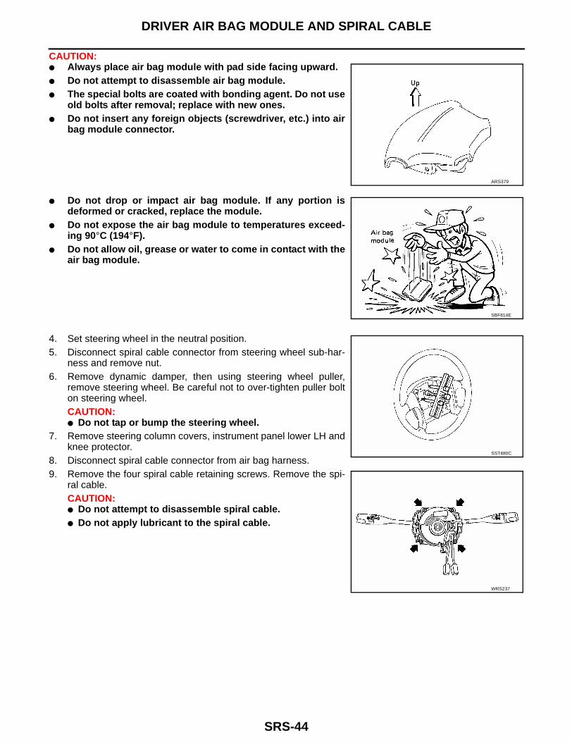
CAUTION:● Always place air bag module with pad side facing upward.● Do not attempt to disassemble air bag module.● The special bolts are coated with bonding agent. Do not use
old bolts after removal; replace with new ones.● Do not insert any foreign objects (screwdriver, etc.) into air
bag module connector.
● Do not drop or impact air bag module. If any portion isdeformed or cracked, replace the module.
● Do not expose the air bag module to temperatures exceed-ing 90°C (194°F).
● Do not allow oil, grease or water to come in contact with theair bag module.
4. Set steering wheel in the neutral position.5. Disconnect spiral cable connector from steering wheel sub-har-
ness and remove nut.6. Remove dynamic damper, then using steering wheel puller,
remove steering wheel. Be careful not to over-tighten puller bolton steering wheel.CAUTION:● Do not tap or bump the steering wheel.
7. Remove steering column covers, instrument panel lower LH andknee protector.
8. Disconnect spiral cable connector from air bag harness.9. Remove the four spiral cable retaining screws. Remove the spi-
ral cable.CAUTION:● Do not attempt to disassemble spiral cable.● Do not apply lubricant to the spiral cable.
ARS379
SBF814E
SST480C
WRS237
DRIVER AIR BAG MODULE AND SPIRAL CABLE
SRS-45
C
D
E
F
G
I
J
K
L
M
A
B
SRS
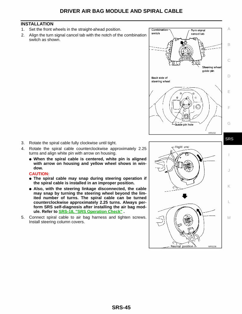
INSTALLATION1. Set the front wheels in the straight-ahead position.2. Align the turn signal cancel tab with the notch of the combination
switch as shown.
3. Rotate the spiral cable fully clockwise until tight.4. Rotate the spiral cable counterclockwise approximately 2.25
turns and align white pin with arrow on housing.● When the spiral cable is centered, white pin is aligned
with arrow on housing and yellow wheel shows in win-dow.
CAUTION:● The spiral cable may snap during steering operation if
the spiral cable is installed in an improper position.● Also, with the steering linkage disconnected, the cable
may snap by turning the steering wheel beyond the lim-ited number of turns. The spiral cable can be turnedcounterclockwise approximately 2.25 turns. Always per-form SRS self-diagnosis after installing the air bag mod-ule. Refer to SRS-18, "SRS Operation Check" .
5. Connect spiral cable to air bag harness and tighten screws.Install steering column covers.
ARS152
WRS238

SRS-46
DRIVER AIR BAG MODULE AND SPIRAL CABLE
6. Install steering wheel, setting spiral cable pin guide, and pull spi-ral cable connectors through.
7. Install dynamic damper.8. Tighten steering wheel nut.
9. Position driver air bag module and install two new hex headbolts.
10. Connect driver air bag module connector.● For removal/installation of the direct-connect SRS connectors,
refer to SRS-7, "Direct-connect SRS Component Connectors" . 11. Install all lids and steering switches.12. Connect both battery cables.
● If equipped with VDC, refer to BRC-55, "Adjustment of Steer-ing Angle Sensor Neutral Position" for steering wheel anglesensor adjustment.
13. Conduct self-diagnosis to ensure entire SRS operates properly.(Use CONSULT-II or “AIR BAG” warning lamp check.) Turn the steering wheel fully to the right and left tocheck that the spiral cable is set in the neutral position.
14. If “AIR BAG” warning lamp blinks (in User mode), it shows the spiral cable may be snapped due to itsimproper position. Perform self-diagnosis again. (Use CONSULT-II or “AIR BAG” warning lamp check.) Ifa malfunction is detected, replace the spiral cable with a new one.
NOTE:● After replacement, perform self-diagnosis for SRS. Refer to SRS-18, "SRS Operation Check" .
: 29 - 39 N·m (3.0 - 4.0 kg-m, 22 - 29 ft-lb)
WRS239
WRS235

FRONT PASSENGER AIR BAG MODULE
SRS-47
C
D
E
F
G
I
J
K
L
M
A
B
SRS
FRONT PASSENGER AIR BAG MODULE PFP:K8515
Rmoval and Installation EHS000LW
REMOVALCAUTION:● Before servicing SRS, turn the ignition switch OFF, disconnect both battery cables and wait for at
least 3 minutes.● Always work from the side of an air bag module.1. Open glove box assembly.2. Reach up and bend down deformable connector mounting
bracket assembly.
3. Remove passenger air bag module connector clip from bracket.4. Disconnect passenger air bag module connector from air bag harness connector.5. Remove glove box and instrument panel lower passenger side. Refer to IP-10, "INSTRUMENT PANEL
ASSEMBLY" .
WRS261

SRS-48
FRONT PASSENGER AIR BAG MODULE
6. Remove two hex head bolts.7. Remove four mounting nuts.8. Remove passenger air bag module by releasing the clips from
the top of the instrument panel.
● The air bag module is heavy and should be supported usingboth hands during removal.
CAUTION:● Always place air bag module with pad side facing upward.● Do not attempt to disassemble air bag module.● The special bolts are coated with a bonding agent. Do not
use old bolts after removal; replace with new coated bolts.● Do not insert any foreign objects (screwdriver, etc.) into air
bag module connector.
● Do not drop or impact air bag module. If any portion isdeformed or cracked, replace the module.
● Do not expose the air bag module to temperatures exceed-ing 90°C (194°F).
● Do not allow oil, grease or water to come in contact with theair bag module.
● After air bag inflates, the instrument panel assembly shouldbe replaced if damaged.
WRS240
ARS330
SBF814E

FRONT PASSENGER AIR BAG MODULE
SRS-49
C
D
E
F
G
I
J
K
L
M
A
B
SRS
INSTALLATIONCAUTION:● Always work from the side of an air bag module.1. Install passenger air bag module in instrument panel.
1. Insert front edge of passenger air bag module first to easeinstallation.
– Ensure harness is not caught between passenger air bagmodule and support bracket.
2. Install four mounting nuts.3. Install two new hex head bolts.
2. Install instrument panel lower passenger side and glove box.
3. Connect passenger air bag module connector to air bag harnessconnector.
4. Attach passenger air bag module connector clip to lid.5. Close lid and glove box.6. Connect both battery cables.7. Conduct self-diagnosis to ensure entire SRS operates properly.
(Use CONSULT-II or “AIR BAG” warning lamp check.)NOTE:● After replacement, perform self-diagnosis for SRS. Refer to
SRS-18, "SRS Operation Check" .
WRS240
WRS261

SRS-50
SIDE CURTAIN AIR BAG MODULE
SIDE CURTAIN AIR BAG MODULE PFP:985P0
Removal and Installation EHS000LO
REMOVALCAUTION:● Before servicing SRS, turn the ignition switch off, disconnect both battery cables and wait at least
3 minutes.● Always work from the side of the side curtain air bag module.1. Remove headlining. Refer to EI-24, "Removal and Installation" .2. Remove three rearmost side curtain air bag inflator attaching bolts, and unhook the side curtain air bag
inflator.3. Disconnect side curtain air bag connector.
● For removal/installation of the direct-connect SRS connectors, refer to SRS-7, "Direct-connect SRSComponent Connectors" .
4. Unclip wiring harness from side curtain air bag module bracket.5. Remove side curtain air bag module attaching bolts and remove the side curtain air bag module.
CAUTION:● Always place the side curtain air bag module with the warn-
ing label facing upward.● Do not attempt to disassemble side curtain air bag module.● Do not insert any foreign objects (screwdriver, etc.) into air
bag module connector.
WHIA0078E
WHIA0079E

SIDE CURTAIN AIR BAG MODULE
SRS-51
C
D
E
F
G
I
J
K
L
M
A
B
SRS
● Replace side curtain air bag module if it has been droppedor sustained an impact.
● Do not expose the air bag module to temperatures exceed-ing 90°C (194°F).
● Do not allow oil, grease or water to come in contact with theside curtain air bag module.
INSTALLATIONTo install, reverse the removal procedure.● For removal/installation of the direct-connect SRS connectors, refer to SRS-7, "Direct-connect SRS Com-
ponent Connectors" .CAUTION:● Always work from the side of the side curtain air bag module.● After replacement of side curtain air bag module, perform self-diagnosis to check that no malfunc-
tion is detected. Refer to SRS-18, "SRS Operation Check" .
SBF814E

SRS-52
DISPOSAL OF AIR BAG MODULE AND SEAT BELT PRE-TENSIONER
DISPOSAL OF AIR BAG MODULE AND SEAT BELT PRE-TENSIONER PFP:00014
Disposal of Air Bag Module and Seat Belt Pre-tensioner EHS000IV
● Before disposing of air bag modules and seat belt pre-tensioners, or vehicles equipped with such sys-tems, deploy the systems. If such systems have already been deployed due to an accident, dispose of asindicated in SRS-52, "Disposal of Air Bag Module and Seat Belt Pre-tensioner" .
● When deploying air bag module or seat belt pre-tensioner, always use the Special Service Tool; Deploy-ment tool KV99106400 (Kent-Moore No. J38381).
● When deploying air bag module or seat belt pre-tensioner, stand at least 5 m (16 ft) away from the deploy-ment component.
● When deploying air bag module or seat belt pre-tensioner, a fairly loud noise is made, followed by smokebeing released. The smoke is not poisonous, however, be careful not to inhale smoke as it irritates thethroat and can cause choking.
● Only activate one air bag module or seat belt pre-tensioner at a time.● Due to heat, leave air bag module unattended for more than 30 minutes after deployment. Leave seat belt
pre-tensioner unattended for more than 10 minutes after deployment.● Be sure to wear gloves when handling a deployed air bag module or seat belt pre-tensioner.● Never apply water to a deployed air bag module or seat belt pre-tensioner.● Wash your hands clean after finishing work.● Place the vehicle outdoors with an open space of at least 6 m (20 ft) on all sides when deploying air bag
module or seat belt pre-tensioner while mounted in vehicle.● Use a voltmeter to make sure the vehicle battery is fully charged.● Do not dispose of the air bag module or seat belt pre-tensioner un-deployed.
CHECKING DEPLOYMENT TOOLConnecting to Battery
CAUTION:The battery must show voltage of 9.6V or more.Remove the battery from the vehicle and place it on dry wood blocks approximately 5 m (16 ft) away from thevehicle.● Wait 3 minutes after the vehicle battery is disconnected before proceeding.● Connect red clip of deployment tool [SST: KV99106400 (J38381)] to battery positive terminal and black
clip to negative terminal.CAUTION:Make sure the polarity is correct. The right side lamp on the deployment tool [SST: KV99106400(J38381)], marked “DEPLOYMENT TOOL POWER”, should glow with a green light. If the right sidelamp glows red, reverse the connections to the battery.
SRS019

DISPOSAL OF AIR BAG MODULE AND SEAT BELT PRE-TENSIONER
SRS-53
C
D
E
F
G
I
J
K
L
M
A
B
SRS
Deployment Tool CheckPress the deployment tool [SST: KV99106400 (J38381)] switch tothe ON position. The left side lamp on the deployment tool [SST:KV99106400 (J38381)], marked “AIR BAG CONNECTOR VOLT-AGE”, should illuminate. If it does not illuminate, replace the tool.
Air Bag Deployment Tool Lamp Illumination Chart (Battery connected)
*: If this lamp glows red, the tool is connected to the battery incorrectly. Reverse the connections and make sure the lamp glows green.
DEPLOYMENT PROCEDURES FOR AIR BAG MODULE (OUTSIDE OF VEHICLE)Unless the vehicle is being scrapped, deploying the air bag modulesin the vehicle is not recommended. This may cause damage to thevehicle interior.Anchor air bag module bracket [KV99105300 (J41246)] in a visesecured to a firm foundation during deployment.
Deployment of Driver Air Bag Module (Outside of vehicle)1. Using wire, secure driver air bag module to air bag module
bracket [SST: KV99105300 (J41246)] at two places.CAUTION:If a gap exists between driver air bag module and air bagmodule bracket, use a piece of wood inserted in the gap tostabilize the air bag module.Use wire of at least 1 mm (0.04 in) diameter.
2. Firmly secure air bag module bracket [SST: KV99105300(J41246)] with driver air bag module attached, in a vise.
3. Connect deployment tool adapter [SST: J38381-80-A] to deploy-ment tool [SST: KV99106400 (J38381)] connector and to driverair bag module connector.
4. Connect red clip of deployment tool [SST: KV99106400(J38381)] to battery positive terminal and black clip to negativeterminal.
5. The right side lamp on the deployment tool [SST: KV99106400(J38381)], marked “DEPLOYMENT TOOL POWER”, shouldglow green, not red.
6. Press the button on the deployment tool [SST: KV99106400(J38381)]. The left side lamp on the deployment tool [SST:
SBF266H
Switch operationLeft side lamp, green*
“AIR BAG CONNECTOR VOLTAGE”
Right side lamp, green*“DEPLOYMENT TOOL
POWER”
OFF OFF ON
ON ON ON
ARS185
WRS241
WRS242

SRS-54
DISPOSAL OF AIR BAG MODULE AND SEAT BELT PRE-TENSIONER
KV99106400 (J38381)], marked “AIR BAG CONNECTOR VOLTAGE”, will illuminate and the air bag mod-ule will deploy.
CAUTION:When deploying the air bag module, stand at least 5 m (16 ft) away from the air bag module.
Deployment of Passenger Air Bag Module (Outside of vehicle)1. Make an 8.5 mm (0.335 in) diameter hole in air bag module
bracket [SST: KV99105300 (J41246)] at the position shown.
2. Firmly secure air bag module bracket [SST: KV99105300(J41246)] in a vise.
3. Match the two holes in air bag module bracket [SST:KV99105300 (J41246)] (held in vise) and passenger air bagmodule and attach it with two bolts [M8 x 25 - 30 mm (0.98 - 1.18in)].
CAUTION:If a gap exists between passenger air bag module and air bagmodule bracket, use a piece of wood inserted in the gap to sta-bilize the air bag module.
4. Connect deployment tool adapter [SST: J38381-65] to deploy-ment tool [SST: KV99106400 (J38381)] connector and passen-ger air bag module connector.
ARS371
ARS185
ARS234
WRS262

DISPOSAL OF AIR BAG MODULE AND SEAT BELT PRE-TENSIONER
SRS-55
C
D
E
F
G
I
J
K
L
M
A
B
SRS
5. Connect red clip of deployment tool [SST: KV99106400(J38381)] to battery positive terminal and black clip to negativeterminal.
6. The right side lamp on the deployment tool [SST: KV99106400(J38381)], marked “DEPLOYMENT TOOL POWER”, shouldglow green, not red.
7. Press the button on the deployment tool [SST: KV99106400(J38381)]. The left side lamp on the deployment tool [SST:KV99106400 (J38381)], marked “AIR BAG CONNECTORVOLTAGE”, will illuminate and the air bag module will deploy.
CAUTION:● When deploying the air bag module, stand at least 5 m (16
ft) away from the air bag module.
Deployment of Side Curtain Air Bag Module (Outside of vehicle)1. Cut the inflator from side curtain air bag module.
2. Connect deployment tool [SST: KV99106400 (J38381)] to theinflator using deployment tool adapter (J38381-80-A).
3. Put the inflator connected with the deployment tool [SST:KV99106400 (J38381)] into a tire without a wheel.
ARS236
WHIA0083E
WHIA0157E
WHIA0158E

SRS-56
DISPOSAL OF AIR BAG MODULE AND SEAT BELT PRE-TENSIONER
4. Put the tire with the inflator onto another tire without wheel. Addan additional tire without a wheel and then a tire mounted on awheel on top. CAUTION:Tie all tires together with a strap in order keep them stand-ing.
5. Connect red clip of deployment tool to battery positive terminaland black clip to negative terminal.
6. The lamp on the right side of the tool, marked “deployment toolpower”, should glow green, not red.
7. Press the button on the deployment tool. The left side lamp onthe tool, marked “air bag connector voltage”, will illuminate and the air bag module will deploy.CAUTION:When deploying the side curtain air bag module, stand at least 5 m (16 ft) away from the side cur-tain air bag module.
WHIA0048E

DISPOSAL OF AIR BAG MODULE AND SEAT BELT PRE-TENSIONER
SRS-57
C
D
E
F
G
I
J
K
L
M
A
B
SRS
Deployment of Seat Belt Pre-tensioner (Outside of vehicle)1. Firmly anchor seat belt pre-tensioner in a vise, then cut webbing
off.
2. Connect deployment tool [SST: KV99106400 (J38381)] anddeployment tool adapter [SST: J38381-80-A] connector to seatbelt pre-tensioner.
3. Connect red clip of deployment tool [SST: KV99106400(J38381)] to battery positive terminal and black clip to negativeterminal.
4. The right side lamp on the deployment tool [SST: KV99106400(J38381)], marked “DEPLOYMENT TOOL POWER”, shouldglow green, not red.
5. Press the button on the deployment tool [SST: KV99106400(J38381)]. The left side lamp on the deployment tool [SST:KV99106400 (J38381)], marked “AIR BAG CONNECTORVOLTAGE”, will illuminate and the seat belt pre-tensioner willdeploy.
CAUTION:● When deploying the seat belt pre-tensioner, stand at least 5 m (16 ft) away from the seat belt pre-
tensioner.
LRS205
WRS243
WRS244

SRS-58
DISPOSAL OF AIR BAG MODULE AND SEAT BELT PRE-TENSIONER
DEPLOYMENT OF AIR BAG MODULE AND SEAT BELT PRE-TENSIONER WHILE MOUNTED IN VEHICLEWhen disposing of a vehicle, deploy air bag modules and seat belt pre-tensioners while they are mounted invehicle.CAUTION:When deploying air bag module or seat belt pre-tensioner, ensure vehicle is empty.1. Disconnect both battery cables and wait 3 minutes.2. Disconnect air bag module connector or seat belt pre-tensioner connector.3. Connect deployment tool [SST: KV99106400 (SST: J38381)] to air bag module or seat belt pre-tensioner,
use deployment tool adapter [SST: J38381-80-A].For passenger air bag module, use deployment tool adapter [J38381-65] to attach passenger air bagmodule to deployment tool [SST: KV99106400 (SST: J38381)].
4. Connect red clip of deployment tool [SST: KV99106400(J38381)] to battery positive terminal and black clip to negativeterminal.
5. The right side lamp on the deployment tool [SST: KV99106400(J38381)], marked “DEPLOYMENT TOOL POWER”, shouldglow green, not red.
6. Press the button on the deployment tool [SST: KV99106400(J38381)]. The left side lamp on the deployment tool [SST:KV99106400 (J38381)], marked “AIR BAG CONNECTORVOLTAGE”, will illuminate and the air bag module or seat beltpre-tensioner will deploy.
DISPOSING OF AIR BAG MODULE AND SEAT BELT PRE-TENSIONERDeployed air bag modules and seat belt pre-tensioners are very hot.Before disposing of air bag modules and seat belt pre-tensioners,wait at least 30 minutes and 10 minutes, respectively. Seal them in aplastic bag before disposal.CAUTION:● Never apply water to a deployed air bag module or seat belt
pre-tensioner.● Be sure to wear gloves when handling a deployed air bag
module or seat belt pre-tensioner.● No poisonous gas is produced upon air bag module or seat
belt pre-tensioner deployment. However, be careful not toinhale gas since it irritates the throat and can cause chok-ing.
● Do not attempt to disassemble air bag module or seat belt pre-tensioner.● Air bag module or seat belt pre-tensioner cannot be reused.● Wash your hands clean after finishing work.
ARS343
SBF276H

COLLISION DIAGNOSIS
SRS-59
C
D
E
F
G
I
J
K
L
M
A
B
SRS
COLLISION DIAGNOSIS PFP:00015
Collision Diagnosis EHS000J5
To repair the SRS, perform the following steps.When SRS is activated in a collision:1. Replace the air bag diagnosis sensor unit.2. Remove the air bag modules and seat belt pre-tensioner assemblies.3. Check the SRS components using the table shown below:– Replace any SRS components showing visible signs of damage (dents, cracks and deformation).4. Install new air bag modules and seat belt pre-tensioner assemblies.5. Conduct self-diagnosis using CONSULT-II or “AIR BAG” warning lamp. Refer to SRS-18, "SRS Operation
Check" . Ensure entire SRS operates properly.When SRS is not activated in a collision:1. Check the SRS components using the table shown below:– Replace any SRS components showing visible signs of damage (dents, cracks and deformation).2. Conduct self-diagnosis using CONSULT-II or “AIR BAG” warning lamp. Refer to SRS-18, "SRS Operation
Check" . Ensure entire SRS operates properly.
SRS INSPECTION (FOR FRONTAL COLLISION)Part SRS is activated SRS is NOT activated
Air bag module (driver and passenger side)
REPLACEInstall with new spe-cial bolts coated with bonding agent.
1. Remove air bag module. Check harness cover and connectors for damage, termi-nals for deformities, and harness for binding.
2.
– Install driver air bag module into the steering wheel to check fit and alignment with the wheel.
– Install passenger air bag module into the instrument panel to check fit with the instrument panel.
3. No damage found, reinstall with new bolts coated with bonding agent.
4. If damaged—REPLACE. Install air bag modules with new special bolts coated with bonding agent. Air bag must be deployed before discarding.
Seat belt pre-ten-sioner assembly
REPLACEInstall seat belt pre-tensioner with new bolts.
1. Remove seat belt pre-tensioners.Check harness cover and connectors for damage, terminals for deformities, and harness for binding.
2. Check belts for damage and anchors for loose mounting.
3. Check retractor for smooth operation.
4. If no damage is found, reinstall seat belt pre-tensioner assembly.
5. If damaged—REPLACE. Install the seat belt pre-tensioners with new bolts coated with bonding agent. Seat belt pre-tensioners must be deployed before discarding.
Crash zone sensor REPLACE the crash zone sensor and bracket with new nuts and bolts coated with bonding agent.
1. Remove the crash zone sensor. Check harness connectors for damage, terminals for deformities, and harness for binding.
2. Check for visible signs of damage (dents, cracks, deformation) of the crash zone sensor and bracket.
3. Install the crash zone sensor to check fit.
4. If no damage is found, reinstall the crash zone sensor with new nuts coated with bonding agent.
5. If damaged—REPLACE the crash zone sensor and bracket with new nuts and bolts coated with bonding agent.
Air bag diagnosis sensor unit
REPLACEInstall with new bolts coated with bonding agent.
1. Check case for dents, cracks or deformities.
2. Check connectors for damage, and terminals for deformities.
3. If no damage is found, reinstall with new special bolts a nd ground bolt coated with bonding agent.
4. If damaged—REPLACE. Install diagnosis sensor unit with new special bolts and ground bolt coated with bonding agent.

SRS-60
COLLISION DIAGNOSIS
Steering wheel 1. Visually check steering wheel for deformities.
2. Check harness and connectors for damage, and terminals for deformities.
3. Install air bag module to check fit or alignment with steering wheel.
4. Check steering wheel for excessive free play.
5. If no damage is found, reinstall with new bolts.
6. If damaged—REPLACE.
Spiral cable 1. Visually check spiral cable and combination switch for damage.
2. Check connectors and protective tape for damage.
3. Check steering wheel for noise, binding or heavy operation.
4. If no damage is found, reinstall with new bolts.
5. If damaged—REPLACE.
Harness and Connec-tors
1. Check connectors for poor connection, damage, and terminals for deformities.
2. Check harness for binding, chafing, cuts, or deformities.
3. If no damage is found, reinstall the harness and connectors.
4. Damaged—REPLACE damaged harness. Do not attempt to repair, splice or modify any SRS harness.
Instrument panel 1. When passenger air bag inflates, check the following points for bending, deformities or cracks.
– Opening portion for passenger air bag
– Passenger air bag module brackets
– The portions securing the instrument panel
2. If no damage is found, reinstall the instrument panel.
3. If damaged—REPLACE the instrument panel with new bolts.
Part SRS is activated SRS is NOT activated
ARS237
ARS238
ARS372
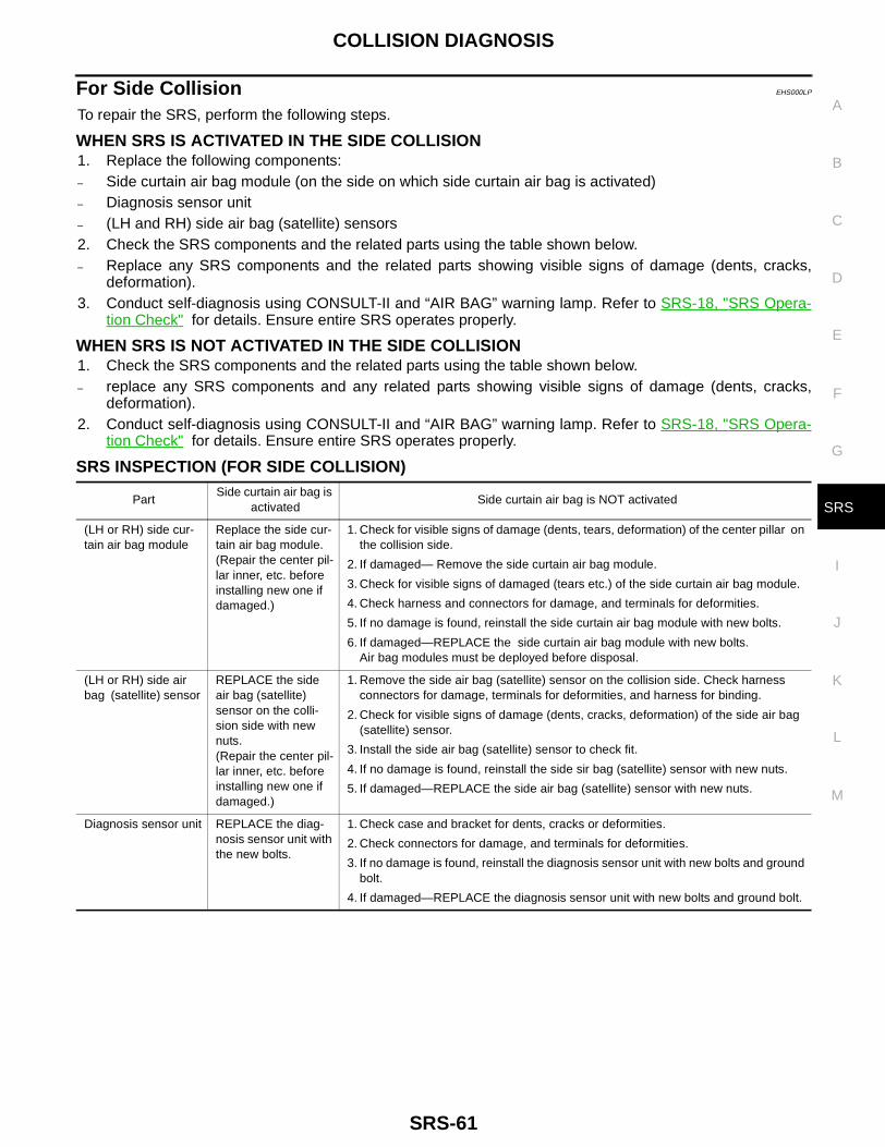
COLLISION DIAGNOSIS
SRS-61
C
D
E
F
G
I
J
K
L
M
A
B
SRS
For Side Collision EHS000LP
To repair the SRS, perform the following steps.
WHEN SRS IS ACTIVATED IN THE SIDE COLLISION1. Replace the following components:– Side curtain air bag module (on the side on which side curtain air bag is activated)– Diagnosis sensor unit– (LH and RH) side air bag (satellite) sensors2. Check the SRS components and the related parts using the table shown below.– Replace any SRS components and the related parts showing visible signs of damage (dents, cracks,
deformation).3. Conduct self-diagnosis using CONSULT-II and “AIR BAG” warning lamp. Refer to SRS-18, "SRS Opera-
tion Check" for details. Ensure entire SRS operates properly.
WHEN SRS IS NOT ACTIVATED IN THE SIDE COLLISION1. Check the SRS components and the related parts using the table shown below.– replace any SRS components and any related parts showing visible signs of damage (dents, cracks,
deformation).2. Conduct self-diagnosis using CONSULT-II and “AIR BAG” warning lamp. Refer to SRS-18, "SRS Opera-
tion Check" for details. Ensure entire SRS operates properly.
SRS INSPECTION (FOR SIDE COLLISION)
PartSide curtain air bag is
activated Side curtain air bag is NOT activated
(LH or RH) side cur-tain air bag module
Replace the side cur-tain air bag module.(Repair the center pil-lar inner, etc. before installing new one if damaged.)
1. Check for visible signs of damage (dents, tears, deformation) of the center pillar on the collision side.
2. If damaged— Remove the side curtain air bag module.
3. Check for visible signs of damaged (tears etc.) of the side curtain air bag module.
4. Check harness and connectors for damage, and terminals for deformities.
5. If no damage is found, reinstall the side curtain air bag module with new bolts.
6. If damaged—REPLACE the side curtain air bag module with new bolts. Air bag modules must be deployed before disposal.
(LH or RH) side air bag (satellite) sensor
REPLACE the side air bag (satellite) sensor on the colli-sion side with new nuts.(Repair the center pil-lar inner, etc. before installing new one if damaged.)
1. Remove the side air bag (satellite) sensor on the collision side. Check harness connectors for damage, terminals for deformities, and harness for binding.
2. Check for visible signs of damage (dents, cracks, deformation) of the side air bag (satellite) sensor.
3. Install the side air bag (satellite) sensor to check fit.
4. If no damage is found, reinstall the side sir bag (satellite) sensor with new nuts.
5. If damaged—REPLACE the side air bag (satellite) sensor with new nuts.
Diagnosis sensor unit REPLACE the diag-nosis sensor unit with the new bolts.
1. Check case and bracket for dents, cracks or deformities.
2. Check connectors for damage, and terminals for deformities.
3. If no damage is found, reinstall the diagnosis sensor unit with new bolts and ground bolt.
4. If damaged—REPLACE the diagnosis sensor unit with new bolts and ground bolt.

SRS-62
COLLISION DIAGNOSIS
Seat belt pre-ten-sioner assembly
1. Check if the seat belt can be extended smoothly.If the seat belt cannot be extended smoothly,
– Check for deformities of the center pillar inner.
– If the center pillar inner has no damage, REPLACE the seat belt pre-tensioner assembly.
2. Remove the seat belt pre-tensioner assembly on the collision side. Check harness cover and connectors for damage, terminals for deformities, and harness for binding.
3. Check for visible signs of damage (dents, cracks, deformation) of the seat belt pre-tensioner assembly.
4. Check seat belt adjuster for damage.
5. If no damage is found, reinstall the seat belt pre-tensioner assembly.
6. If damaged—REPLACE the seat belt pre-tensioner assembly with new bolts. The seat belt pre-tensioner assembly must be deployed before disposing of it.
Center inner pillar 1. Check the center inner pillar on the collision side for damage (dents, cracks, deformation).
2. If damaged—REPAIR the center inner pillar.
Trim/headliner 1. Check for visible signs of damage (dents, cracks, deformation) of the interior trim on the collision side.
2. If damaged—REPLACE the damaged trim parts.
PartSide curtain air bag is
activated Side curtain air bag is NOT activated