Section B - ggn.dronacharya.infoggn.dronacharya.info/MEDept/Downloads/QuestionBank/IIIsem/md... ·...
45
Section B •Orthographic projections: principle of first and third angle projection, orthographic views from isometric views of machine parts / components. •Drawing of sectional views:- Coupling, Crankshaft, Pulley, Piston and Connecting rod, Cotter and Knuckle joint. Riveted Joint and Welded Joint.
Transcript of Section B - ggn.dronacharya.infoggn.dronacharya.info/MEDept/Downloads/QuestionBank/IIIsem/md... ·...
Section B
•Orthographic projections: principle of first andthird angle projection, orthographic views from isometric views of machine parts / components.
•Drawing of sectional views:- Coupling,Crankshaft, Pulley, Piston and Connecting rod, Cotter and Knuckle joint. Riveted Joint and Welded Joint.

Orthographic Projections
• Orthographic projections are
drawings where the projectors,
the observer or station point
remain parallel to each other and
perpendicular to the plane of
projection.
• Orthographic projections are
further subdivided into axonome
tric projections and multi-view
projections.
• Effective in technical
representation of objects
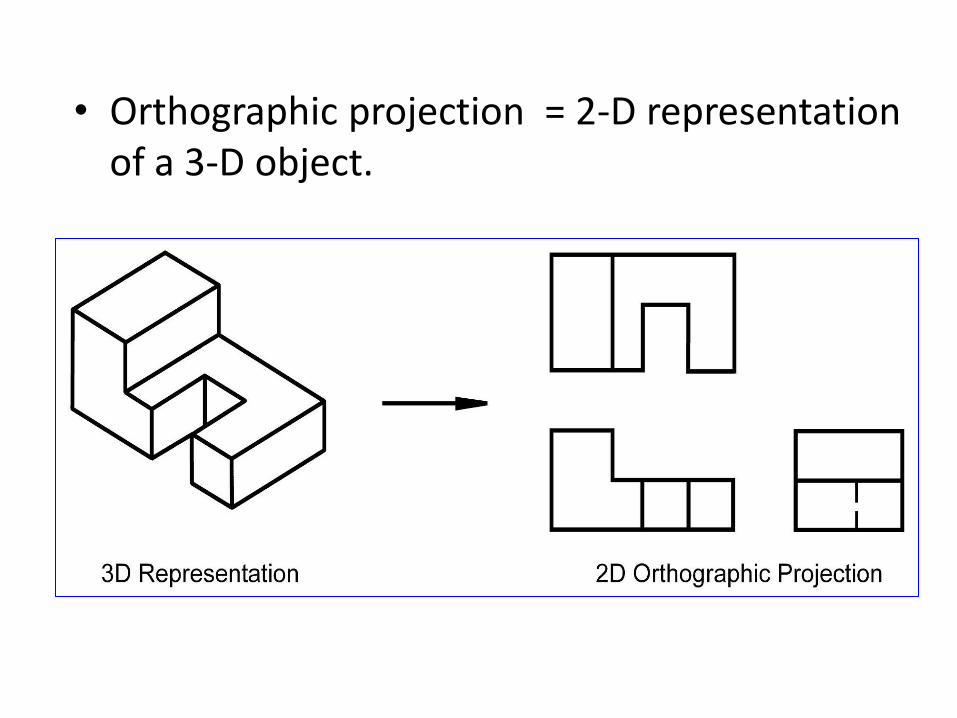
• Orthographic projection = 2-D representationof a 3-D object.
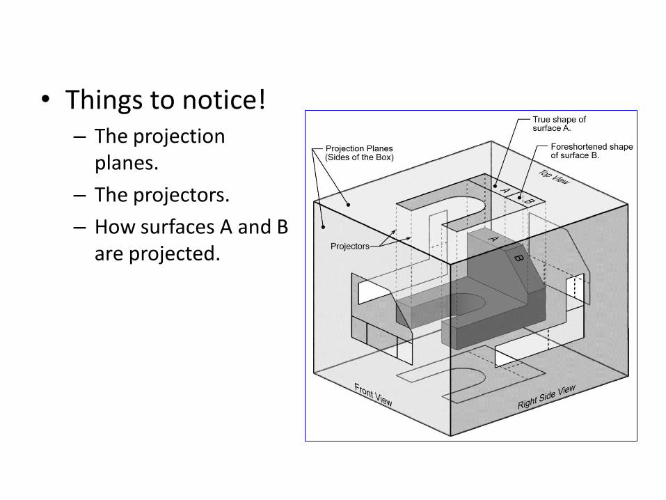
• Things to notice!– The projection
planes.
– The projectors.
– How surfaces A and Bare projected.

Name each view.
Top
RearLeft Side
Bottom
Right Side

• When constructing an orthographic projection,we need to include enough views to completelydescribe the true shape of the part.– Complex part = more views– Simple part = less views
• The standard views used in an orthographicprojection are;– Front view– Top view– Right side view
• The remaining 3 views usually don’t add any newinformation.
Standard Views

Line Type and Weight
• There are four commonly used line types;
– continuous
– hidden
– center
– phantom
• Some lines are more important than others.Importance is indicated by line weight orthickness.
– The thicker the line, the more important it is.

Line Type and Weight
• Visible lines:
– Visible lines represent visible edges and boundaries.
– Continuous and thick (0.5 - 0.6 mm).
• Hidden lines:
– Hidden lines represent edges and boundaries that cannotbe seen.
– Dashed and medium thick (0.35 - 0.45 mm).

Line Type and Weight
• Center lines:
– Represent axes of symmetry.
– Long dash – short dash and thin (0.3 mm).
• Phantom line:
– Phantom lines are used to indicate imaginaryfeatures.
• alternate positions of moving parts
• adjacent positions of related parts
– The line type is long dash – short dash – shortdash and the line weight is usually thin (0.3 mm).
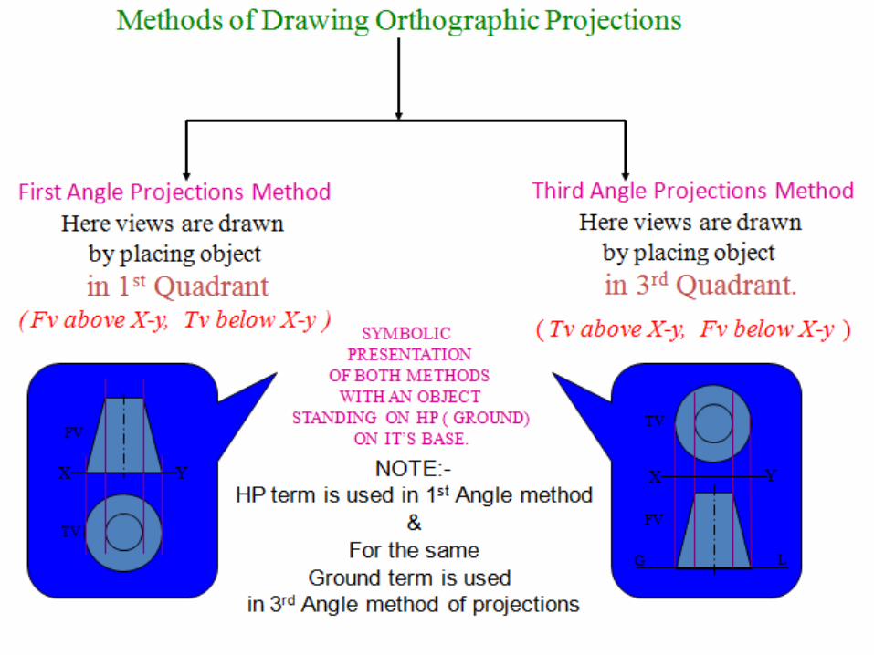

Projection Symbol
• United States = 3rd angle projection
• Europe = 1st angle projection

First Angle Projection

How to draw plan and elevation?

Points to remember:
• The ‘front view’ (or elevation) is the viewwith maximum information.
• The ‘plan’ is below the ‘elevation’ (inprojection).
• The ‘end view’ is placed on the right ifviewed from left side of object and on theleft if viewed from right side.
• ‘End view’ and plan face inwards from‘elevation’.

Third Angle Projection

In 3rd angle projection planes are transparent and objects are viewed through them
How to draw plan and elevation?

Points to remember:
• The ‘front view’ (or elevation) is the view with
maximum information.
• The ‘plan’ is above the ‘elevation’ (in projection).
• The ‘end view’ is placed on the right if viewedfrom right side of object and on the left if viewedfrom left side.
• ‘End view’ and plan face outwards from‘elevation’.

x y
FRONT VIEW
TOP VIEW
L.H.SIDE VIEW
FOR T.V.
PICTORIAL PRESENTATION IS GIVEN
DRAW THREE VIEWS OF THIS OBJECT
BY FIRST ANGLE PROJECTION METHOD
ORTHOGRAPHIC PROJECTIONS

FOR T.V.
ORTHOGRAPHIC PROJECTIONS
X Y
FRONT VIEW
TOP VIEW
L.H.SIDE VIEW
PICTORIAL PRESENTATION IS GIVEN
DRAW THREE VIEWS OF THIS OBJECT
BY FIRST ANGLE PROJECTION METHOD

FOR T.V.
ORTHOGRAPHIC PROJECTIONS
FRONT VIEW
TOP VIEW
L.H.SIDE VIEW
X Y
PICTORIAL PRESENTATION IS GIVEN
DRAW THREE VIEWS OF THIS OBJECT
BY FIRST ANGLE PROJECTION METHOD

FOR T.V.
PICTORIAL PRESENTATION IS GIVEN
DRAW THREE VIEWS OF THIS OBJECT
BY FIRST ANGLE PROJECTION METHOD
ORTHOGRAPHIC PROJECTIONS
FRONT VIEW
TOP VIEW
L.H.SIDE VIEW
X Y

FOR T.V.
PICTORIAL PRESENTATION IS GIVEN
DRAW THREE VIEWS OF THIS OBJECT
BY FIRST ANGLE PROJECTION METHOD
ORTHOGRAPHIC PROJECTIONS
FRONT VIEW
TOP VIEW
L.H.SIDE VIEW
X Y

Drawing of sectional views
• Coupling,
• Crankshaft,
• Pulley,
• Piston and Connecting rod,
• Cotter and Knuckle joint,
• Riveted Joint,
• Welded Joint.
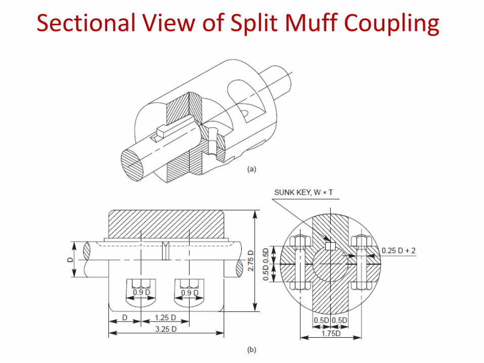
Sectional View of Split Muff Coupling

Sectional View of Flanged Coupling
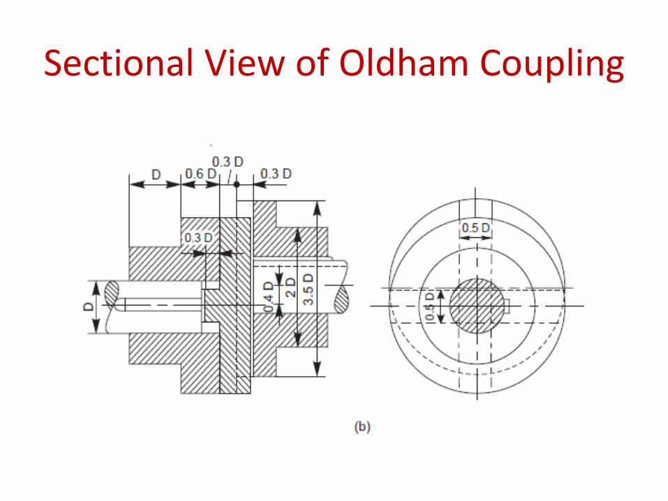
Sectional View of Oldham Coupling

Sectional View of V-Belt Pulley

Petrol Engine Connecting Rod

Cotter joint with socket and spigot ends

Knuckle joint

Rivet Joint

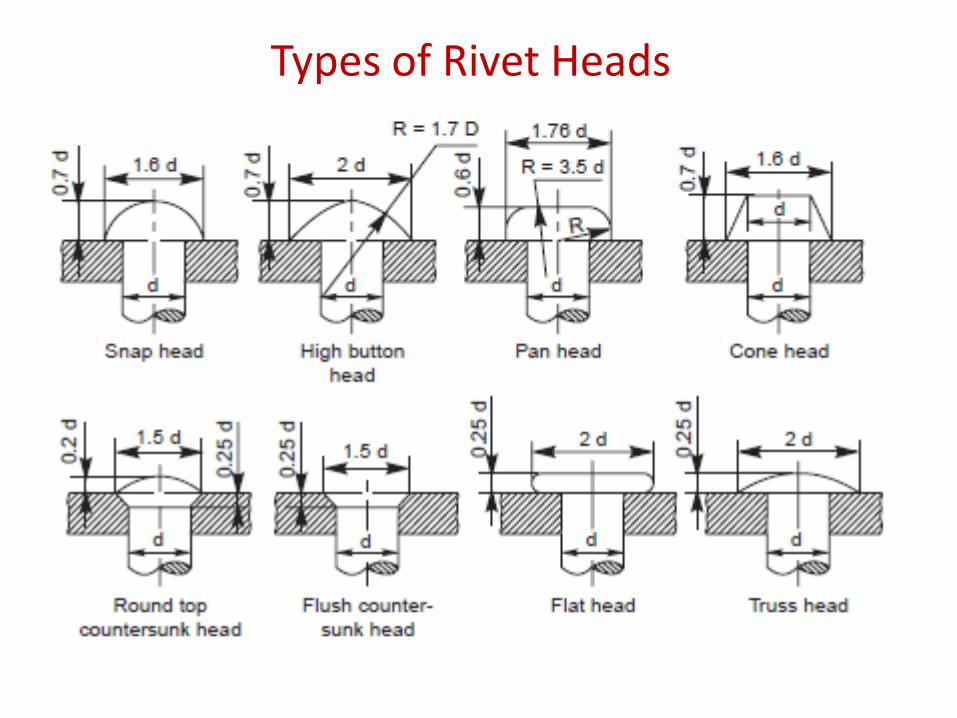
Types of Rivet Heads
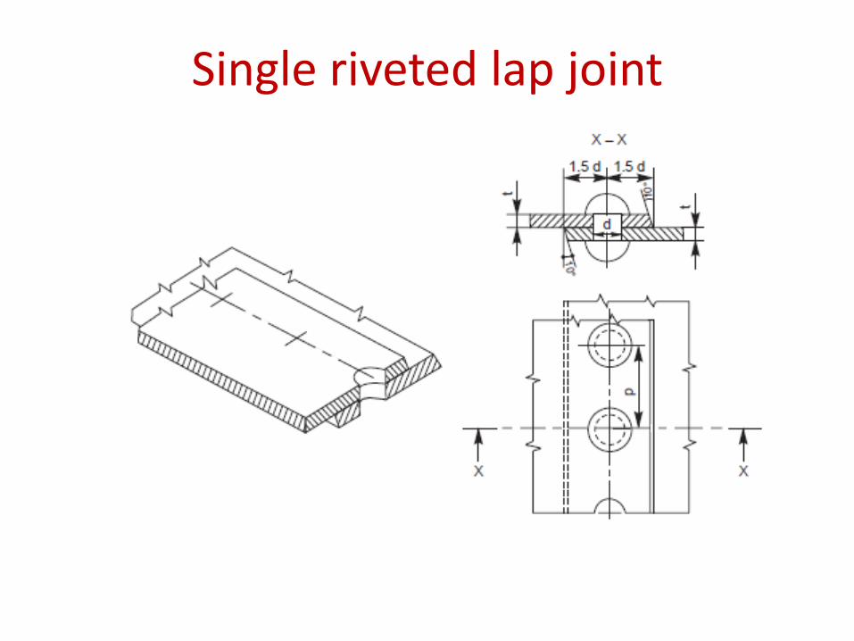
Single riveted lap joint

Double riveted chain lap joint

Double riveted zig-zag lap joint

Single riveted, single strap butt joint

Single riveted, double strap butt joint

Double riveted, double strap butt joint

Double riveted, double strap zig-zagbutt joint

Double strap diamond butt joint

Basic terms of a welded joint

Types of welded Joint
(i) An arrow line (1) per joint,
(ii) A dual reference line, consisting of two parallel lines; one continuous and one dashed (2a, 2b) and
(iii) A certain number of dimensions (4) and conventional signs (3).
Position of weld symbol on drawing

Elementary welding symbols

Elementary welding symbols