Section 7 O2 and A/F Sensor Diagnosis - Testroetetestroete.com/car/Toyota/mr2...
44
Section 7 O2 and A/F Sensor Diagnosis Engine Control Systems II - Course 874 1. Determine the condition of an O2 sensor, A/F sensor and heater based on data and engine symptoms and determine appropriate repair. 2. Use Modes 5, 6, and 7 to determine monitored O2 sensor results. 3. Accurately measure and interpret oxygen content of the exhaust gases based on sensor signal data. 4. Describe the primary difference between the O2 sensor and the A/F sensor. 5. Use Modes 6 and 7 to determine monitored A/F sensor results. Learning Objectives: Cover Platinum Electrode Platinum Electrode Heater Coating (Ceramic) Solid Electrolyte (Zirconia Element) Exhaust Gas
Transcript of Section 7 O2 and A/F Sensor Diagnosis - Testroetetestroete.com/car/Toyota/mr2...

Section 7
O2 and A/F Sensor Diagnosis
Engine Control Systems II - Course 874
1.Determine the condition of an O2 sensor, A/F sensor and heaterbased on data and engine symptoms and determine appropriaterepair.
2.Use Modes 5, 6, and 7 to determine monitored O2 sensor results.
3.Accurately measure and interpret oxygen content of the exhaustgases based on sensor signal data.
4.Describe the primary difference between the O2 sensor and the A/F sensor.
5.Use Modes 6 and 7 to determine monitored A/F sensor results.
Learning Objectives:
Cover
Platinum Electrode
Platinum Electrode
Heater
Coating (Ceramic)
Solid Electrolyte(Zirconia Element)
Exhaust Gas
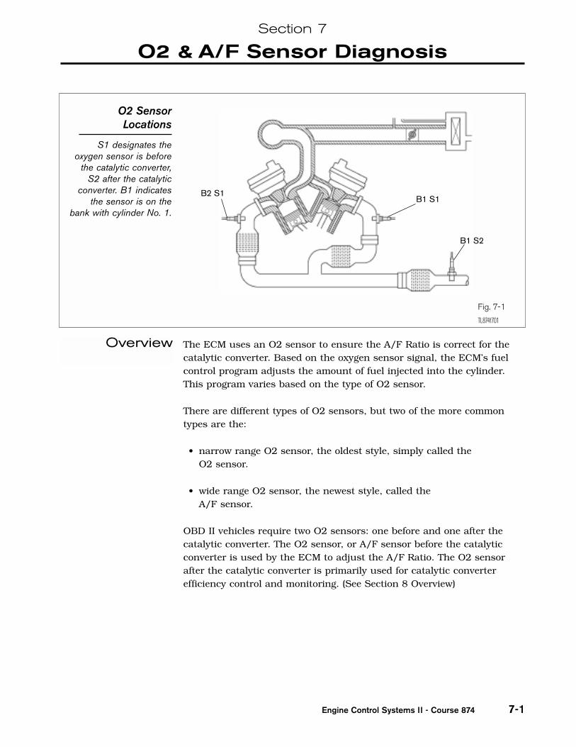
The ECM uses an O2 sensor to ensure the A/F Ratio is correct for thecatalytic converter. Based on the oxygen sensor signal, the ECM’s fuelcontrol program adjusts the amount of fuel injected into the cylinder.This program varies based on the type of O2 sensor.
There are different types of O2 sensors, but two of the more commontypes are the:
• narrow range O2 sensor, the oldest style, simply called the O2 sensor.
• wide range O2 sensor, the newest style, called the A/F sensor.
OBD II vehicles require two O2 sensors: one before and one after thecatalytic converter. The O2 sensor, or A/F sensor before the catalyticconverter is used by the ECM to adjust the A/F Ratio. The O2 sensorafter the catalytic converter is primarily used for catalytic converterefficiency control and monitoring. (See Section 8 Overview)
Section 7
O2 & A/F Sensor Diagnosis
Engine Control Systems II - Course 874 7-1
O2 SensorLocations
S1 designates theoxygen sensor is before
the catalytic converter,S2 after the catalytic
converter. B1 indicatesthe sensor is on the
bank with cylinder No. 1.
Fig. 7-1
TL874f701
B2 S1B1 S1
B1 S2
Overview
Section 7
TOYOTA Technical Training7-2
The O2 sensor monitor checks for sensor circuit malfunctions, slowresponse rate, and for a malfunction of the sensor’s heater circuit.There is a DTC for each condition for each sensor. The sub-sensor(S2) isnot monitored for response rate. O2 sensors are required to bemonitored once per trip, however, the ECM continuously monitors O2sensor operation.
When the ECM sees the right conditions, the ECM will test the O2sensors for performance by measuring the signal response as the fuelinjected into the cylinder is varied. The faster the O2 sensor responds,the better the sensor. Mode 5 will report the results of this monitor test.
The repair confirmation drive pattern in the Repair Manual provides thedriving conditions for the ECM to operate the O2 sensor monitor.
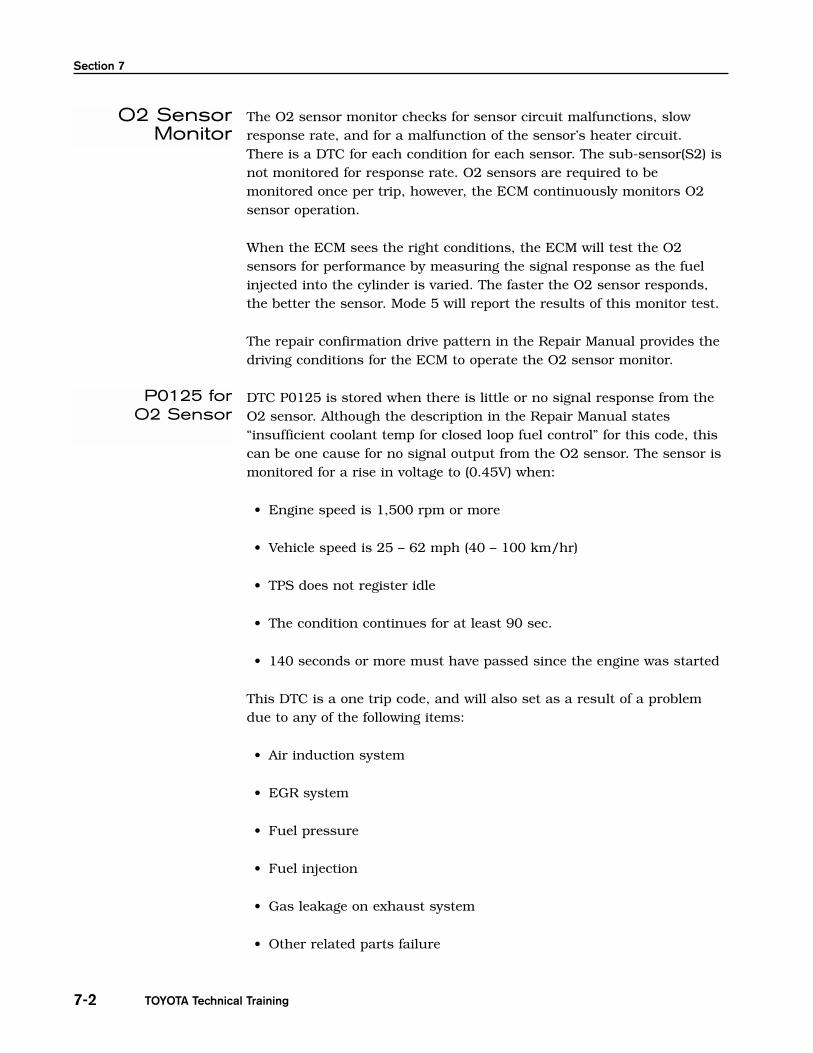
DTC P0125 is stored when there is little or no signal response from theO2 sensor. Although the description in the Repair Manual states“insufficient coolant temp for closed loop fuel control” for this code, thiscan be one cause for no signal output from the O2 sensor. The sensor ismonitored for a rise in voltage to (0.45V) when:
• Engine speed is 1,500 rpm or more
• Vehicle speed is 25 – 62 mph (40 – 100 km/hr)
• TPS does not register idle
• The condition continues for at least 90 sec.
• 140 seconds or more must have passed since the engine was started
This DTC is a one trip code, and will also set as a result of a problemdue to any of the following items:
• Air induction system
• EGR system
• Fuel pressure
• Fuel injection
• Gas leakage on exhaust system
• Other related parts failure
O2 SensorMonitor
P0125 forO2 Sensor

O2 & A/F Sensor Diagnosis
7-3
This DTC will set when a sensor output has very little or no activity.
A lean condition or an inoperative sensor will have very little activity.
If the vehicle runs out of fuel, the A/F Ratio is lean and DTC P0125 maybe recorded. This DTC will also set if no signal is received by the ECM; forexample, an open circuit (broken wire).
This portion of the monitor is concerned with sensor voltage output.These DTC(s) set if the output voltage stays high or low during the testperiod.
Engine Control Systems II - Course 874
NOTE
HINT
P0130, P0150:O2 Sensor
Output Voltage
Fig. 7-2
TL874f702
O2 Sensor MonitorP0130, P0150 (Output Voltage)

Section 7
TOYOTA Technical Training7-4
The ECM monitors the response of the O2 sensor.
This part of the monitor is concerned with the time the O2 sensor takesto switch from .35V and .55V.
The failure threshold for switching can be as much as 1.1 seconds(max).
P0133, P0153:O2 Sensor
Response Rate
NOTE
Fig. 7-3
TL874f703
O2 Sensor Monitor P0133, P0153 (Response Rate)
O2 & A/F Sensor Diagnosis
7-5
This mode displays the test results of the O2 sensor test monitor. Thesevalues are stored values, not current values that are found in Mode 1(DATA LIST). Not all test values are applicable to all manufacturers. TheA/F sensor test values are not applicable and are not displayed in Mode 5. Some vehicles use Non-Continuous Test Results mode to reportresults.
The following is a definition for the displayed terms under Mode 5, O2STest Results:
• R>>L O2S V Rich to lean threshold voltage – voltage used by the ECMto determine the boundary line when going from rich to leanL>>R O2S V Lean to rich threshold voltage – voltage used by the ECMto determine the boundary line when going from lean to rich
• LOW SW V Low sensor voltage point for switch time calculation –value used by the ECM for switch time calculationHIGH SW V High sensor voltage point for switch time calculation –value used by the ECM for switch time calculation
• R>>L SW TIM Rich to lean switch time – time in seconds it takes toswitch from Rich to Lean based on high to low switch voltagesL>>R SW TIM Lean to rich switch time – time in seconds it takes toswitch from Rich to Lean based on low to high switch voltages
• MIN O2S V Minimum sensor voltage during the test cycleMAX O2S V Maximum sensor voltage during the test cycle
• O2S TRANS T Time between sensor transitions – time between therich to lean and lean to rich threshold voltages
Engine Control Systems II - Course 874
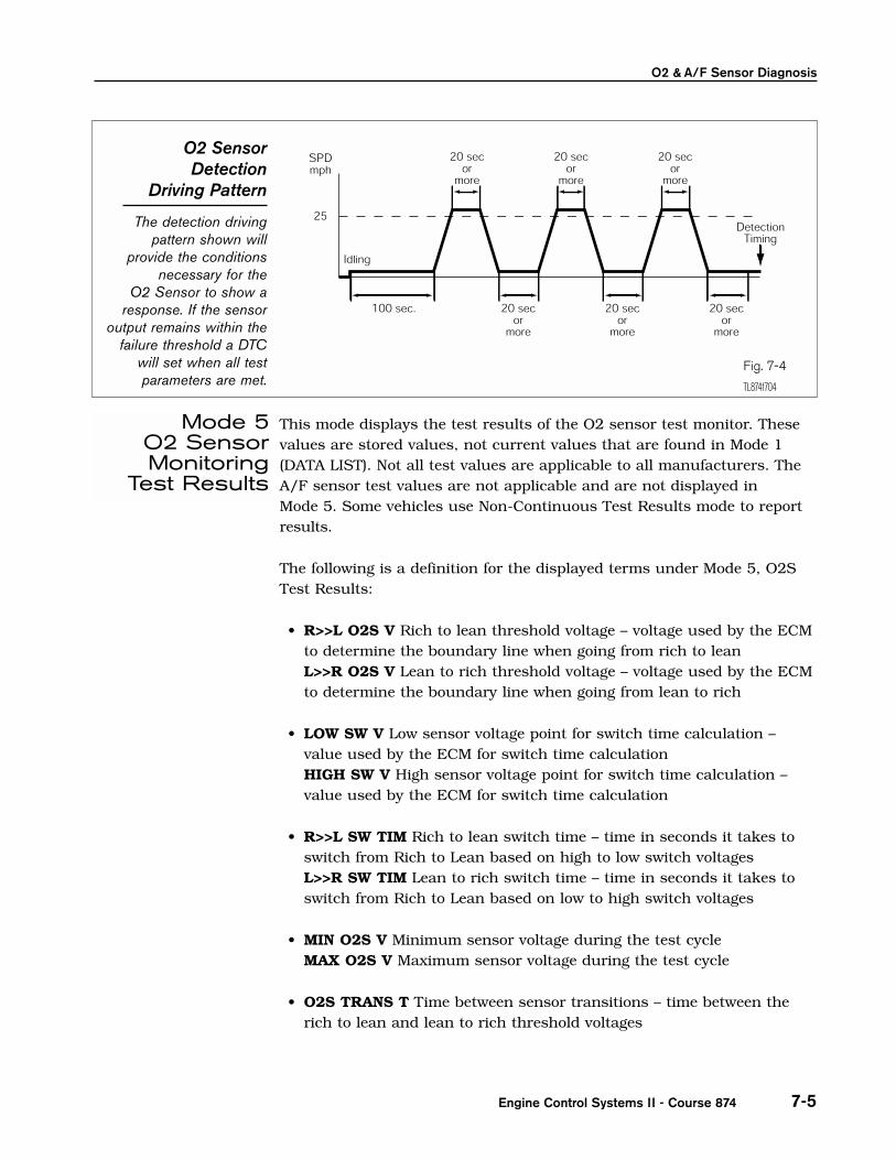
O2 SensorDetection
Driving Pattern
The detection drivingpattern shown will
provide the conditionsnecessary for the
O2 Sensor to show aresponse. If the sensor
output remains within thefailure threshold a DTC
will set when all testparameters are met.
Fig. 7-4
TL874f704
Mode 5 O2 SensorMonitoring
Test Results

Section 7
TOYOTA Technical Training7-6
• TID $30 – The amount of time, used as a reference for the number(counts) each time the O2 sensor signal crosses the low and highsensor voltage pointsTID $70 – The number of counts, determined by the number oftimes the signal crossed the low and high sensor voltage points
This screens data can be used as a report on the condition of the O2sensor. A malfunctioning sensor will switch slowly or not at all. Pleasekeep in mind that other factors can affect O2 sensor performance.
O2 Sensor Monitoring Screens - Mode 5
These screens are found under the CARB section, O2S Test results.
Fig. 7-5
TL874f705
O2 SENSOR TEST (B1 - S1)
LOW SW V............ 0.350VHIGH SW V........... 0.550VMIN O2S V........... 0.025VMAX O2S V........... 0.790VTime $31............. 0.04sTime $32............. 0.04s
O2 SENSOR TEST (B2 - S2)
MIN O2S V........... 0.085VMAX O2S V........... 0.785V
O2 & A/F Sensor Diagnosis
7-7Engine Control Systems II - Course 874
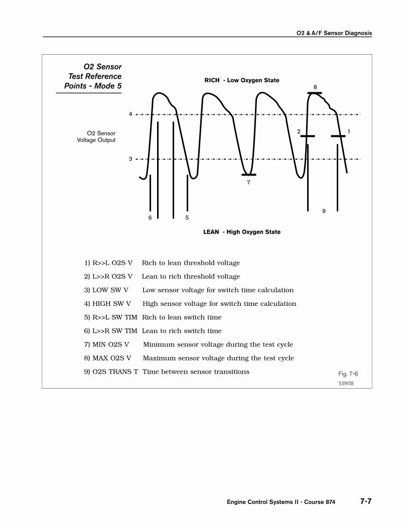
O2 Sensor Test Reference
Points - Mode 5
Fig. 7-6
TL874f706
O2 SensorVoltage Output
LEAN - High Oxygen State
RICH - Low Oxygen State
4
8
12
9
7
56
3
1) R>>L O2S V Rich to lean threshold voltage
2) L>>R O2S V Lean to rich threshold voltage
3) LOW SW V Low sensor voltage for switch time calculation
4) HIGH SW V High sensor voltage for switch time calculation
5) R>>L SW TIM Rich to lean switch time
6) L>>R SW TIM Lean to rich switch time
7) MIN O2S V Minimum sensor voltage during the test cycle
8) MAX O2S V Maximum sensor voltage during the test cycle
9) O2S TRANS T Time between sensor transitions
Section 7
TOYOTA Technical Training7-8
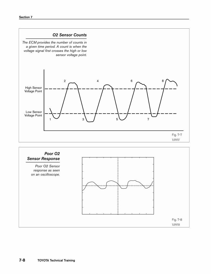
O2 Sensor Counts
The ECM provides the number of counts ina given time period. A count is when the
voltage signal first crosses the high or lowsensor voltage point.
Fig. 7-7
TL874f707
High SensorVoltage Point
Low SensorVoltage Point
1 3 5 7
2 4 6 8
Poor O2 Sensor Response
Poor O2 Sensorresponse as seen
on an oscilloscope.
Fig. 7-8
TL874f708
O2 & A/F Sensor Diagnosis
7-9
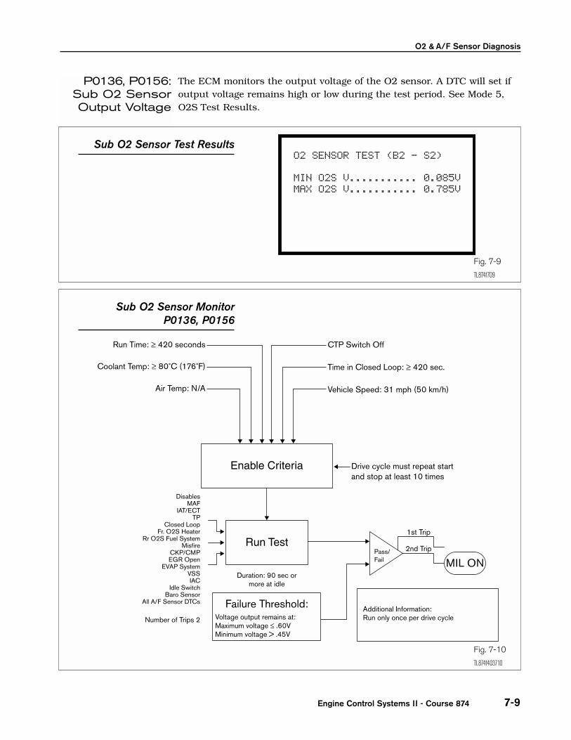
The ECM monitors the output voltage of the O2 sensor. A DTC will set ifoutput voltage remains high or low during the test period. See Mode 5,O2S Test Results.
Engine Control Systems II - Course 874
P0136, P0156:Sub O2 SensorOutput Voltage
O2 SENSOR TEST (B2 - S2)
MIN O2S V........... 0.085VMAX O2S V........... 0.785V
Sub O2 Sensor Test Results
Fig. 7-9
TL874f709
Fig. 7-10
TL874f403710
Sub O2 Sensor MonitorP0136, P0156

Section 7
TOYOTA Technical Training7-10
All heated O2 sensors are monitored for abnormal heater condition. TheECM checks the amount of current required for the sensor heater. If thecurrent is too high or too low a DTC will be set.
Sub O2Sensor Detection
Driving Pattern
The detection drivingpattern shown will
provide the conditionsnecessary for the Sub orrear O2 Sensor to showa response. If the sensoroutput remains within the
failure threshold a DTCwill set when all testparameters are met.
Fig. 7-11
TL874f711
Fig. 7-12
TL874f403712
O2 Sensor Heater MonitorP0135, P0141, P0155
(Circuit Current)
P0135, P0141,P0155, P0161:
O2 SensorHeater Monitor

O2 & A/F Sensor Diagnosis
7-11
After the engine is warmed up, heated O2 sensor output does not indicateRICH even when conditions (a), (b), (c) and (d) continue for at least 1.5min.:
a. Engine speed: 1,500 rpm or more
b. Vehicle speed: 25 - 62 mph (40 - 100 km/h)
c. Throttle valve does not fully close
d. 140 sec. or more after starting engine
This DTC can be set due to other related parts failure.
Voltage output of heated O2 sensor remains at 0.40V or more, or 0.55V orless, during idling after the engine is warmed up. Please confirm voltagespecification in vehicle Repair Manual.
(two trip detection logic)
This DTC can be set due to other related parts failure.
Response time for the heated O2 sensor’s voltage output to change fromrich to lean, or from lean to rich, is 1.1 sec. or more during idling afterthe engine is warmed up.
(two trip detection logic)
This DTC can be set due to other related parts failure.
Heater current exceeds 2A or heater current of 0.2A or less when theheater operates. Please confirm heater resistance specification in vehicleRepair Manual.
(two trip detection logic)
This DTC can be set due to other related parts failure.
Engine Control Systems II - Course 874
O2 SensorDTC(s)
P0125:Coolant
TemperatureInsufficient forClosed Loop
Operation (Bank1 or 2 Sensor 1)
P0130:Heated O2
Sensor CircuitMalfunction
(Bank 1 Sensor 1)
P0133:Heated O2
Sensor CircuitSlow Response
(Bank 1 Sensor 1)
P0135:Heated
O2 SensorHeater Circuit
Malfunction(Bank 1
Sensor 1)

Section 7
TOYOTA Technical Training7-12
Voltage output of the heated O2 sensor (bank 1 sensor 2, bank 2 sensor2) remains at 0.4V or more or 0.5V or less when the vehicle is driven at19 mph (30 km/h) or more after the engine is warmed up. Pleaseconfirm voltage specification in vehicle Repair Manual.
(two trip detection logic)
This DTC can be set due to other related parts failure.
Heater current exceeds 2A or heater current of 0.2A or less when theheater operates. Please confirm heater resistance specification in vehicleRepair Manual.
(two trip detection logic)
This DTC can be set due to other related parts failure.
Voltage output of heated O2 sensor remains at 0.40V or more, or 0.55Vor less, during idling after the engine is warmed up. Please confirmvoltage specification in vehicle Repair Manual.
(two trip detection logic)
This DTC can be set due to other related parts failure.
Response time for the heated O2 sensor’s voltage output to change fromrich to lean, or from lean to rich, is 1.1 sec. or more during idling afterthe engine is warmed up.
(two trip detection logic)
This DTC can be set due to other related parts failure.
Heater current exceeds 2A or heater current of 0.2A or less when theheater operates. Please confirm heater resistance specification in vehicleRepair Manual.
(two trip detection logic)
This DTC can be set due to other related parts failure.
P0136:Heated O2
Sensor CircuitMalfunction
(Bank 1 Sensor 2)
P0150: Heated O2
Sensor CircuitMalfunction
(Bank 2 Sensor 1)
P0153:Heated O2
Sensor CircuitSlow Response
(Bank 2 Sensor 1)
P0155:Heated
O2 SensorHeater Circuit
Malfunction(Bank 2 Sensor 1)
P0141: Heated
O2 Sensor Heater Circuit
Malfunction(Bank 1 Sensor 2)
O2 & A/F Sensor Diagnosis
7-13
Voltage output of the heated O2 sensor (bank 1 sensor 2, bank 2 sensor2) remains at 0.4V or more or 0.5V or less when the vehicle is driven at19 mph (30 km/h) or more after the engine is warmed up.
(two trip detection logic)
This DTC can be set due to other related parts failure.
Heater current exceeds 2A or heater current of 0.2A or less when theheater operates.
(two trip detection logic)
This DTC can be set due to other related parts failure.
When an O2 sensor DTC is found, it is important to look at each DTCdescription carefully before proceeding with diagnosis. In addition toP0125, each main O2 sensor has three DTC(s), one for a sensor circuitmalfunction, one for slow response, and one for the sensor’s heatercircuit malfunction.
The sub O2 sensors have two DTC(s), one for a sensor circuit malfunctionand one for the sub-sensor’s heater circuit malfunction. The sub-sensordoes not have a DTC for slow response because a sub-sensor shows verylittle activity during normal operation. Each DTC requires a differentapproach to diagnosis. Refer to the Repair Manual for the properdiagnostic procedure to follow for each DTC.
The CARB section of the diagnostic tester and the Readiness TestConfirmation procedure can be very useful for O2 sensor diagnosis,particularly Modes 5, 6, and 7. The following screen flows are guides.Varying conditions will have an effect on the outcome.
Engine Control Systems II - Course 874
P0156: Heated O2
Sensor CircuitMalfunction
(Bank 2 Sensor 2)
P0141: Heated O2
Sensor Heater Circuit
Malfunction(Bank 2 Sensor 2)
O2 SensorMonitor
Diagnosis
Section 7
TOYOTA Technical Training7-14
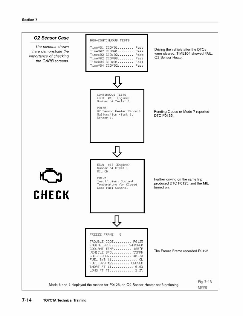
O2 Sensor Case
The screens shownhere demonstrate the
importance of checkingthe CARB screens.
Fig. 7-13
TL874f713
NON-CONTINUOUS TESTS
Time$01 CID$01........ PassTime$02 CID$01........ PassTime$02 CID$02........ PassTime$02 CID$03........ PassTime$04 CID$01........ FailTime$04 CID$02........ Pass
CONTINUOUS TESTS ECU: $10 (Engine) Number of Tests: 1
P0135 O2 Sensor Heater Circuit Malfunction (Bank 1, Sensor 1)
ECU: $10 (Engine) Number of DTCs: 1 MIL ON
P0125 Insufficient Coolant Temperature for Closed Loop Fuel Control
FREEZE FRAME 0
TROUBLE CODE......... P0125ENGINE SPD......... 2415RPMCOOLANT TEMP......... 185˚FVEHICLE SPD.......... 55MPHCALC LOAD............ 40.3%FUEL SYS #1............. OLFUEL SYS #2......... UNUSEDSHORT FT #1........... 0.0%LONG FT #1............ 2.3%
Driving the vehicle after the DTCswere cleared, TIME$04 showed FAIL,O2 Sensor Heater.
Pending Codes or Mode 7 reportedDTC P0135.
Further driving on the same tripproduced DTC P0125, and the MILturned on.
The Freeze Frame recorded P0125.
Mode 6 and 7 displayed the reason for P0125, an O2 Sensor Heater not functioning.
O2 & A/F Sensor Diagnosis
7-15
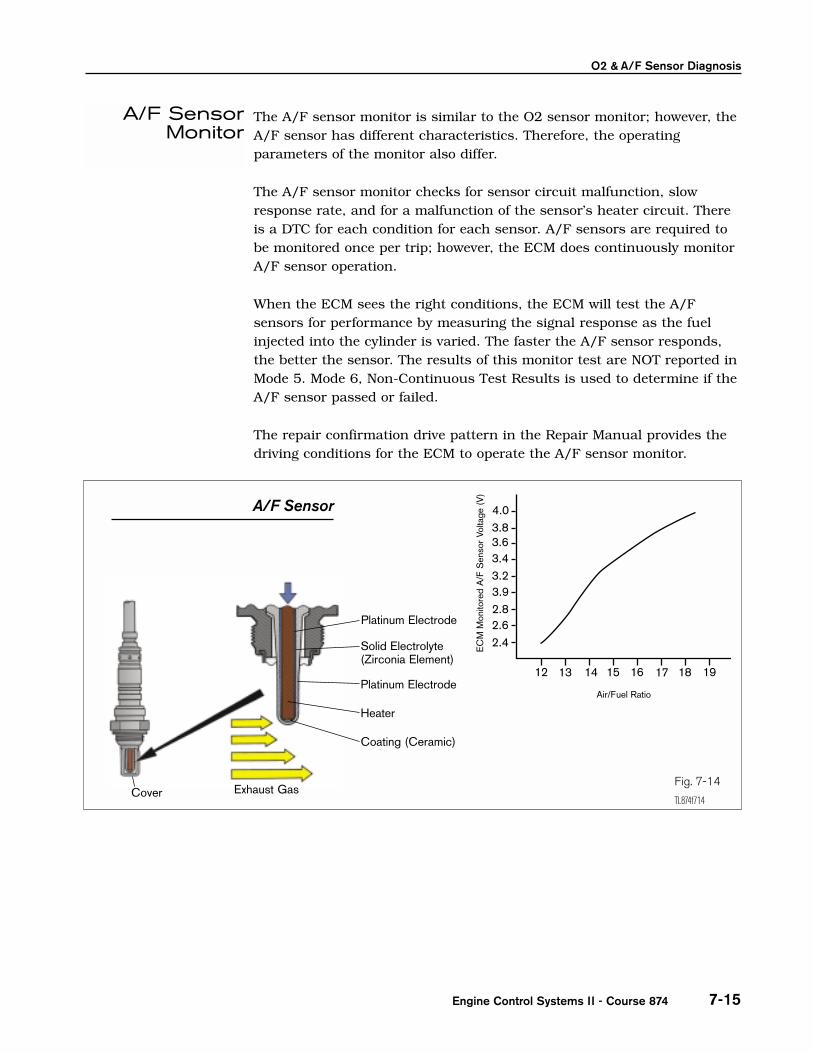
The A/F sensor monitor is similar to the O2 sensor monitor; however, theA/F sensor has different characteristics. Therefore, the operatingparameters of the monitor also differ.
The A/F sensor monitor checks for sensor circuit malfunction, slowresponse rate, and for a malfunction of the sensor’s heater circuit. Thereis a DTC for each condition for each sensor. A/F sensors are required tobe monitored once per trip; however, the ECM does continuously monitorA/F sensor operation.
When the ECM sees the right conditions, the ECM will test the A/Fsensors for performance by measuring the signal response as the fuelinjected into the cylinder is varied. The faster the A/F sensor responds,the better the sensor. The results of this monitor test are NOT reported inMode 5. Mode 6, Non-Continuous Test Results is used to determine if theA/F sensor passed or failed.
The repair confirmation drive pattern in the Repair Manual provides thedriving conditions for the ECM to operate the A/F sensor monitor.
Engine Control Systems II - Course 874
A/F SensorMonitor
A/F Sensor
Fig. 7-14
TL874f714Cover
Platinum Electrode
Platinum Electrode
Heater
Coating (Ceramic)
Solid Electrolyte(Zirconia Element)
Exhaust Gas
Air/Fuel Ratio
EC
MM
onito
red
A/F
Sen
sor
Volta
ge (
V)
4.03.83.63.43.23.92.82.62.4
12 13 15 16 17 18 1914

Section 7
TOYOTA Technical Training7-16
The A/F sensor is similar to the O2 sensor. It appears similar to the O2 sensor, but it is constructed differently and has different operatingcharacteristics.
The A/F sensor is also referred to as a wide range or wide ratio sensorbecause of its ability to detect A/F Ratios over a wide range.
The advantage of using the A/F sensor is that the ECM can moreaccurately meter the fuel reducing emissions.
To accomplish this, the A/F sensor:
• operates at approximately 650°C (1200°F), much hotter than the O2 sensors which operate at 400°C (750°F)
• changes its current (amperage) output in relation to the amount ofoxygen in the exhaust stream
A/F Sensor
A/F SensorDetecting Circuit
The detection circuit,located inside the ECM,
is needed for the A/FSensor to operate. The
A/F Sensor outputcannot be detected
externally. A DiagnosticTester is needed to read
A/F Sensor signaloutput.
Fig. 7-15
TL874f715

A detection circuit in the ECM detects the change and strength of currentflow and puts out a voltage signal relatively proportional to exhaustoxygen content.
This voltage signal can only be measured by using the Diagnostic Testeror OBD II compatible scan tool. The A/F sensor current output cannot beaccurately measured directly. If a Diagnostic Tester or OBD II compatiblescan tool is used refer to the Repair Manual for conversion, for the outputsignal is different.
The A/F sensor is designed so that at stoichiometry, there is no currentflow and the voltage put out by the detection circuit is 3.3 volts. A richmixture, which leaves very little oxygen in the exhaust stream, producesa negative current flow. The detection circuit will produce a voltage below3.3 volts. A lean mixture, which has more oxygen in the exhaust stream,produces a positive current flow. The detection circuit will now produce avoltage signal above 3.3 volts.
The A/F sensor voltage output is the opposite of what happens in thenarrow range O2 sensor. Voltage output through the detection circuitincreases as the mixture gets leaner.
Exhaust Oxygen Content Current Flow Voltage Signal Air/Fuel MixtureJudged to be:
Low oxygen content – direction Below 3.3 volts Rich
Stoichiometry 0 3.3 volts 14.7:1
High oxygen content + direction Above 3.3 volts Lean
O2 & A/F Sensor Diagnosis
7-17Engine Control Systems II - Course 874
Operation
NOTE
NOTE
Section 7
TOYOTA Technical Training7-18
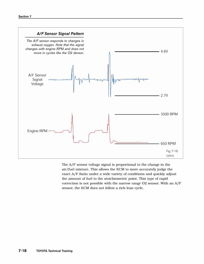
The A/F sensor voltage signal is proportional to the change in theair/fuel mixture. This allows the ECM to more accurately judge theexact A/F Ratio under a wide variety of conditions and quickly adjustthe amount of fuel to the stoichiometric point. This type of rapidcorrection is not possible with the narrow range O2 sensor. With an A/Fsensor, the ECM does not follow a rich lean cycle.
A/F Sensor Signal Pattern
The A/F sensor responds to changes inexhaust oxygen. Note that the signal
changes with engine RPM and does notmove in cycles like the O2 densor.
Fig. 7-16
TL874f716
O2 & A/F Sensor Diagnosis
7-19
DTC P0125 is related to voltage output, although the description statesinsufficient coolant temp for closed loop fuel control. The A/F sensor ismonitored for activity (voltage change) when:
• Engine speed is 1,500 rpm or more
• Vehicle speed is 25 – 62 mph (40 – 100 kph)
• TPS does not register idle
• The condition continues for at least 90 seconds.
• 140 seconds or more must have passed since the engine was started
This DTC will set when a sensor output has very little or no activity.
A lean condition or an inoperative sensor will have very little activity.
This DTC is a one trip code, and will also set as a result of a problem dueto any of the following items:
• Air induction system
• EGR system
• Fuel pressure
• Fuel injection
• Gas leakage on exhaust system
• Other related parts failure
Engine Control Systems II - Course 874
P0125 for A/F Sensor
HINT
Section 7
TOYOTA Technical Training7-20
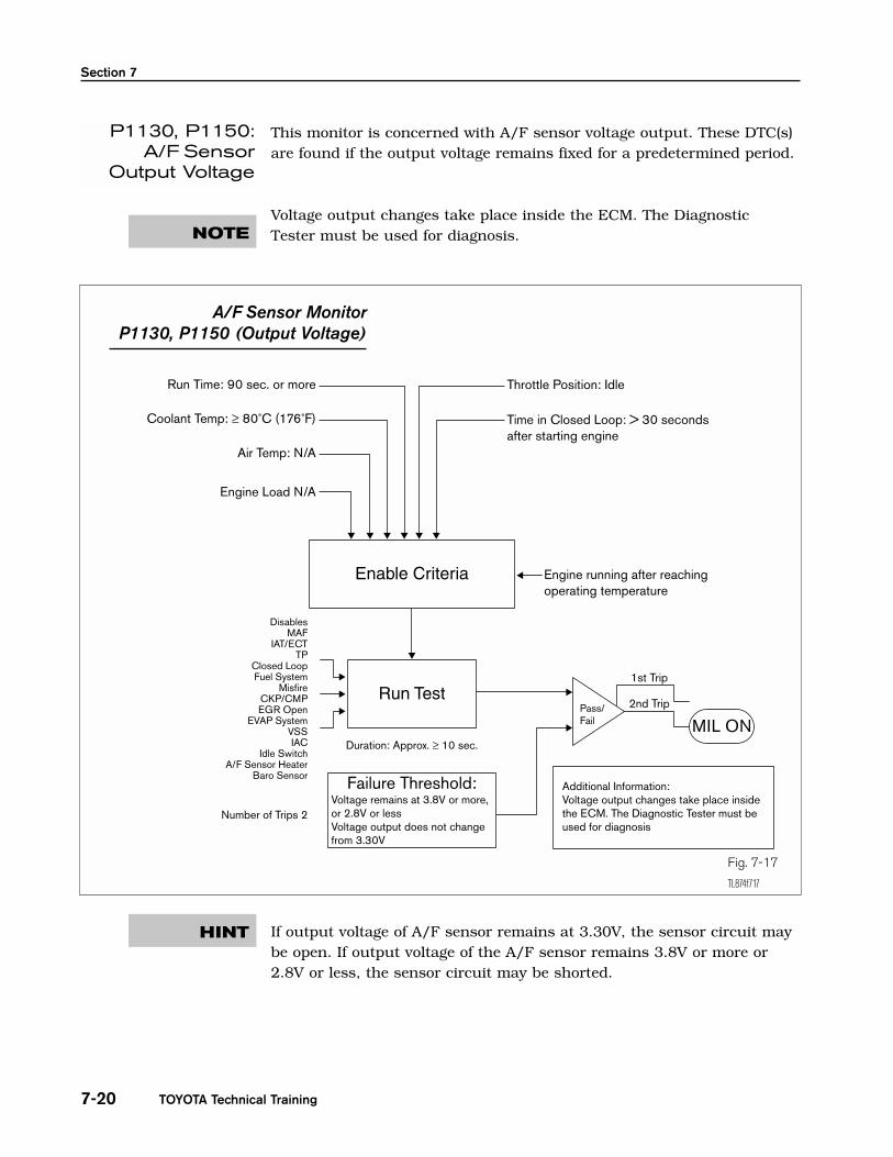
This monitor is concerned with A/F sensor voltage output. These DTC(s)are found if the output voltage remains fixed for a predetermined period.
Voltage output changes take place inside the ECM. The DiagnosticTester must be used for diagnosis.
If output voltage of A/F sensor remains at 3.30V, the sensor circuit maybe open. If output voltage of the A/F sensor remains 3.8V or more or2.8V or less, the sensor circuit may be shorted.
P1130, P1150:A/F Sensor
Output Voltage
NOTE
Fig. 7-17
TL874f717
A/F Sensor Monitor P1130, P1150 (Output Voltage)
HINT
O2 & A/F Sensor Diagnosis
7-21
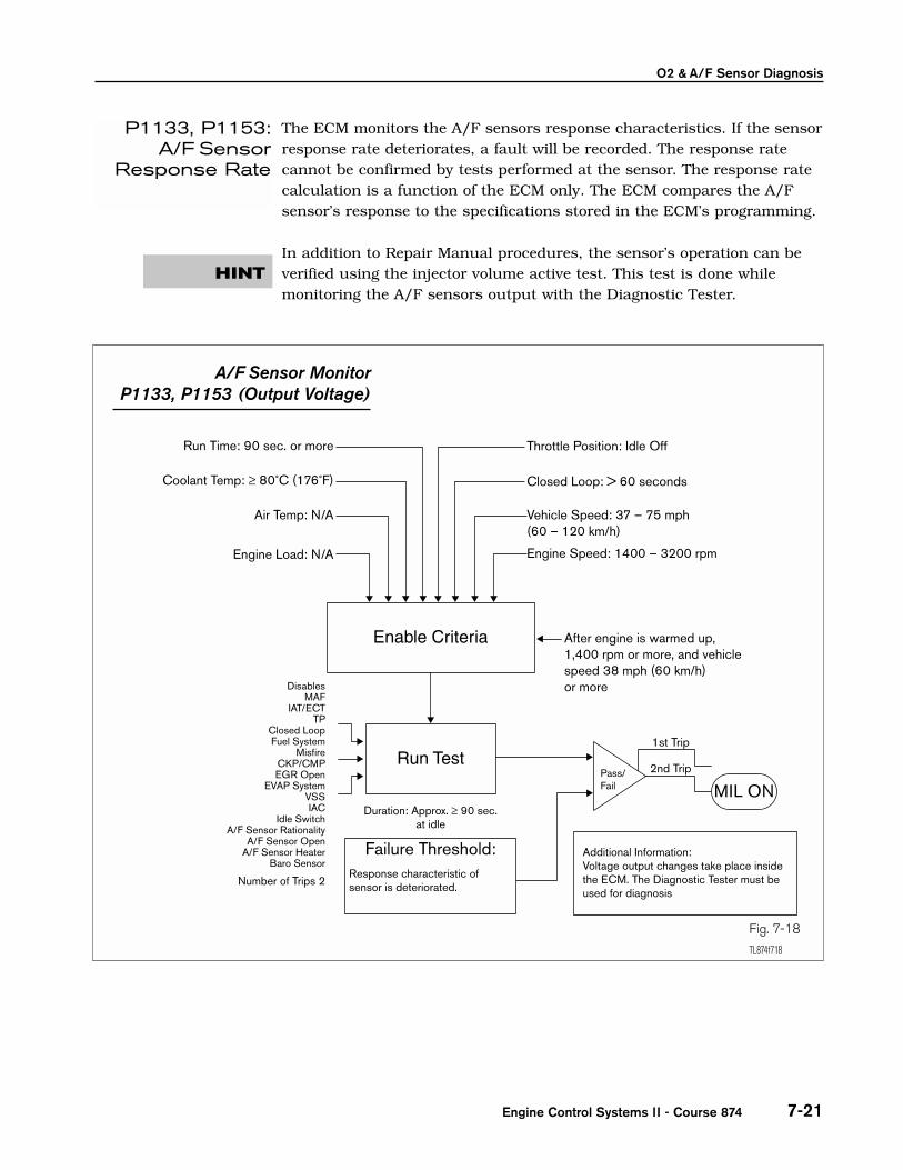
The ECM monitors the A/F sensors response characteristics. If the sensorresponse rate deteriorates, a fault will be recorded. The response ratecannot be confirmed by tests performed at the sensor. The response ratecalculation is a function of the ECM only. The ECM compares the A/Fsensor’s response to the specifications stored in the ECM’s programming.
In addition to Repair Manual procedures, the sensor’s operation can beverified using the injector volume active test. This test is done whilemonitoring the A/F sensors output with the Diagnostic Tester.
Engine Control Systems II - Course 874
P1133, P1153:A/F Sensor
Response Rate
HINT
Fig. 7-18
TL874f718
A/F Sensor Monitor P1133, P1153 (Output Voltage)
Section 7
TOYOTA Technical Training7-22
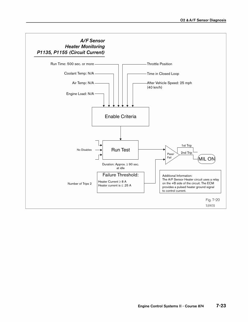
All A/F sensors are monitored for abnormal heater condition. The ECMchecks the amount of current required for the sensor heater. If thecurrent is too high or too low, a DTC will be set. If the current leveldetected is too high, the ECM will shut off the heater. When thishappens, a P0125 can set.
The ECM provides a pulse width modulated control circuit to adjustcurrent through the heater. On engines with two A/F sensors, the A/Fsensor Heater circuit uses a relay on the B+ side of the circuit. In earlymodels, heater DTCs are two trip detection. Beginning with 2001models, a phased change to one trip DTC detection began.
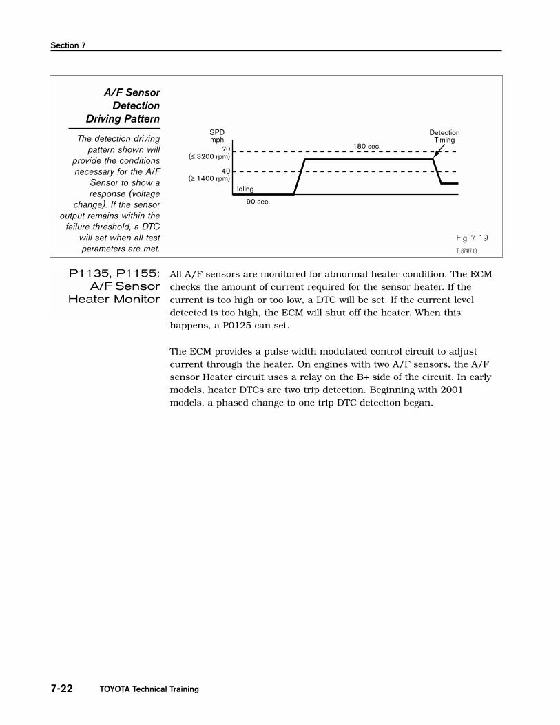
A/F SensorDetection
Driving Pattern
The detection drivingpattern shown will
provide the conditionsnecessary for the A/F
Sensor to show aresponse (voltage
change). If the sensoroutput remains within the
failure threshold, a DTCwill set when all testparameters are met.
Fig. 7-19
TL874f719
P1135, P1155:A/F Sensor
Heater Monitor
O2 & A/F Sensor Diagnosis
7-23Engine Control Systems II - Course 874
Fig. 7-20
TL874f720
A/F Sensor Heater Monitoring
P1135, P1155 (Circuit Current)

Section 7
TOYOTA Technical Training7-24
After the engine is warmed up, A/F sensor Output* does not changewhen conditions (a), (b), (c), and (d) continue for at least 1.5 min.:
a. Engine speed: 1,500 rpm or more
b.Vehicle speed: 25 – 62 mph (40 –100 km/h)
c. Throttle valve is not fully closed
d.140 seconds or more after starting engine
This DTC can be set due to other related parts failure.
DTC P1130 will set from one of the following conditions:
• Voltage output of A/F sensor remains at 3.8V or more, or 2.8V orless, with engine running after the engine is warmed up
• Voltage output of A/F sensor does not change from 3.30V, withengine running after the engine is warmed up
• Open or short in A/F sensor circuit
(two trip detection logic)
This DTC can be set due to other related parts failure.
After the engine reaches operating temperature, engine speed is 1,400rpm or more, vehicle speed 38 mph (60 km/h) or more, and if the A/Fsensor signal response is weaker than normal, DTC P1133 sets.
(two trip detection logic)
This DTC can be set due to other related parts failure.
When the heater operates, heater current exceeds 8A or heater currentis 0.25A or less. Please confirm heater resistance specification in thevehicle Repair Manual.
(two trip detection logic, early models; phased change to one tripdetection beginning 2001 model.)
This DTC can be set due to other related parts failure.
P0125: Coolant
TemperatureInsufficient forClosed Loop
Operation(Bank 1 or 2
Sensor 1)
P1130:Circuit Range/
PerformanceMalfunction
(Bank 1 Sensor 1)
P1133:Circuit Response
Malfuntion(Bank 1 Sensor 1)
A/F SensorDTC(s)
P1135:Heater Circuit
Malfunction(Bank 1 Sensor 1)

O2 & A/F Sensor Diagnosis
7-25
DTC P1150 will set from one of the following conditions:
• Voltage output of A/F sensor remains at 3.8V or more, or 2.8V or less,during engine running after the engine is warmed up
• Voltage output of A/F sensor does not change from 3.30V, duringengine running after the engine is warmed up
• Open or short in A/F sensor circuit
(two trip detection logic)
This DTC can be set due to other related parts failure.
After the engine reaches operating temperature, engine speed is 1,400rpm or more, vehicle speed 38 mph (60 km/h) or more, and if the A/Fsensor signal response is weaker than normal, DTC P1133 sets.
(two trip detection logic)
This DTC can be set due to other related parts failure.
When the heater operates, heater current exceeds 8A or heater current is0.25A or less. Please confirm heater resistance specification in vehicleRepair Manual.
(two trip detection logic, early models; phased change to one tripdetection beginning 2001 model.)
This DTC can be set due to other related parts failure.
When an A/F sensor DTC is found, it is important to look at each DTCdescription carefully before proceeding with diagnosis. In addition toP0125, the A/F sensors each have three DTC(s), one for a sensorrange/performance malfunction, one for response malfunction, and onefor the sensor’s heater circuit malfunction. Each DTC requires a differentapproach to diagnosis. Refer to the Repair Manual for the properdiagnostic procedure to follow for each DTC.
Engine Control Systems II - Course 874
P1150:Circuit Range/
PerformanceMalfunction
(Bank 2 Sensor 1)
P1153:Circuit Response
Malfunction(Bank 2 Sensor 1)
P1155:Heater Circuit
Malfunction(Bank 2 Sensor 1)
NOTE

Section 7
TOYOTA Technical Training7-26
A second generation A/F sensor (referred to here as the planar A/Fsensor) was developed to meet more stringent emission regulations. ThisA/F sensor reaches operating temperature faster than the previous(referred to here as the cup element) A/F sensor. This allows the ECM togo into closed loop fuel control faster when the engine is cold reducingcold start emissions.
The planar A/F sensor has the same detecting range and signalcharacteristics as the previous cup element A/F sensor. The majordifferences are:
• goes into closed loop fuel control faster.
• heater element has a higher resistance.
• heater DTCs set in one trip.
This A/F sensor is not interchangeable with the older, cup element A/F sensor.
Planar A/F Sensor
The newer planar A/Fsensor can be identified
by its shorter body.
The planar has theheater integrated into the
sensing element. Thissensor has the same
detecting range as theprevious, cup type A/F
sensor.
Fig. 7-21
TL874f721
52
653030
Planar Element withIntegrated Heater
Heater
Planar Cup
Cup Element
Planar A/FSensor
Operation
NOTE
O2 & A/F Sensor Diagnosis
7-27
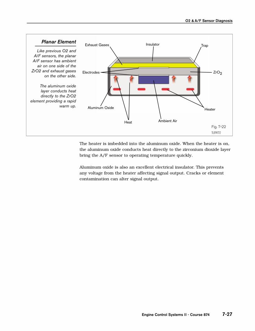
The heater is imbedded into the aluminum oxide. When the heater is on,the aluminum oxide conducts heat directly to the zirconium dioxide layerbring the A/F sensor to operating temperature quickly.
Aluminum oxide is also an excellent electrical insulator. This preventsany voltage from the heater affecting signal output. Cracks or elementcontamination can alter signal output.
Engine Control Systems II - Course 874
Planar Element
Like previous O2 andA/F sensors, the planarA/F sensor has ambient
air on one side of theZrO2 and exhaust gases
on the other side.
The aluminum oxidelayer conducts heatdirectly to the ZrO2
element providing a rapidwarm up.
Fig. 7-22
TL874f722
Exhaust Gases Insulator Trap
Electrodes
Aluminum Oxide
Ambient Air
Heater
Heat
ZrO2
Section 7
TOYOTA Technical Training7-28
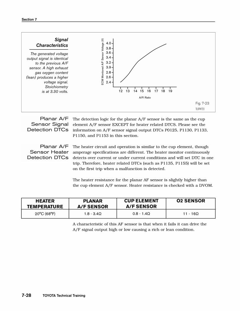
The detection logic for the planar A/F sensor is the same as the cupelement A/F sensor EXCEPT for heater related DTCS. Please see theinformation on A/F sensor signal output DTCs P0125, P1130, P1133,P1150, and P1153 in this section.
The heater circuit and operation is similar to the cup element, thoughamperage specifications are different. The heater monitor continuouslydetects over current or under current conditions and will set DTC in onetrip. Therefore, heater related DTCs (such as P1135, P1155) will be seton the first trip when a malfunction is detected.
The heater resistance for the planar AF sensor is slightly higher thanthe cup element A/F sensor. Heater resistance is checked with a DVOM.
A characteristic of this AF sensor is that when it fails it can drive theA/F signal output high or low causing a rich or lean condition.
SignalCharacteristics
The generated voltageoutput signal is identical
to the previous A/Fsensor. A high exhaust
gas oxygen content(lean) produces a higher
voltage signal.Stoichiometry
is at 3.30 volts.
Fig. 7-23
TL874f723
A/Fl Ratio
EC
MM
onito
red
A/F
Sen
sor
Volta
ge (
V)
4.03.83.63.43.23.92.82.62.4
12 13 15 16 17 18 1914
Planar A/FSensor Signal
Detection DTCs
Planar A/FSensor Heater
Detection DTCs
HEATERTEMPERATURE
PLANARA/F SENSOR
CUP ELEMENTA/F SENSOR
O2 SENSOR
20°C (68°F) 11 - 16Ω1.8 - 3.4Ω 0.8 - 1.4Ω
O2 & A/F Sensor Diagnosis
7-29Engine Control Systems II - Course 874
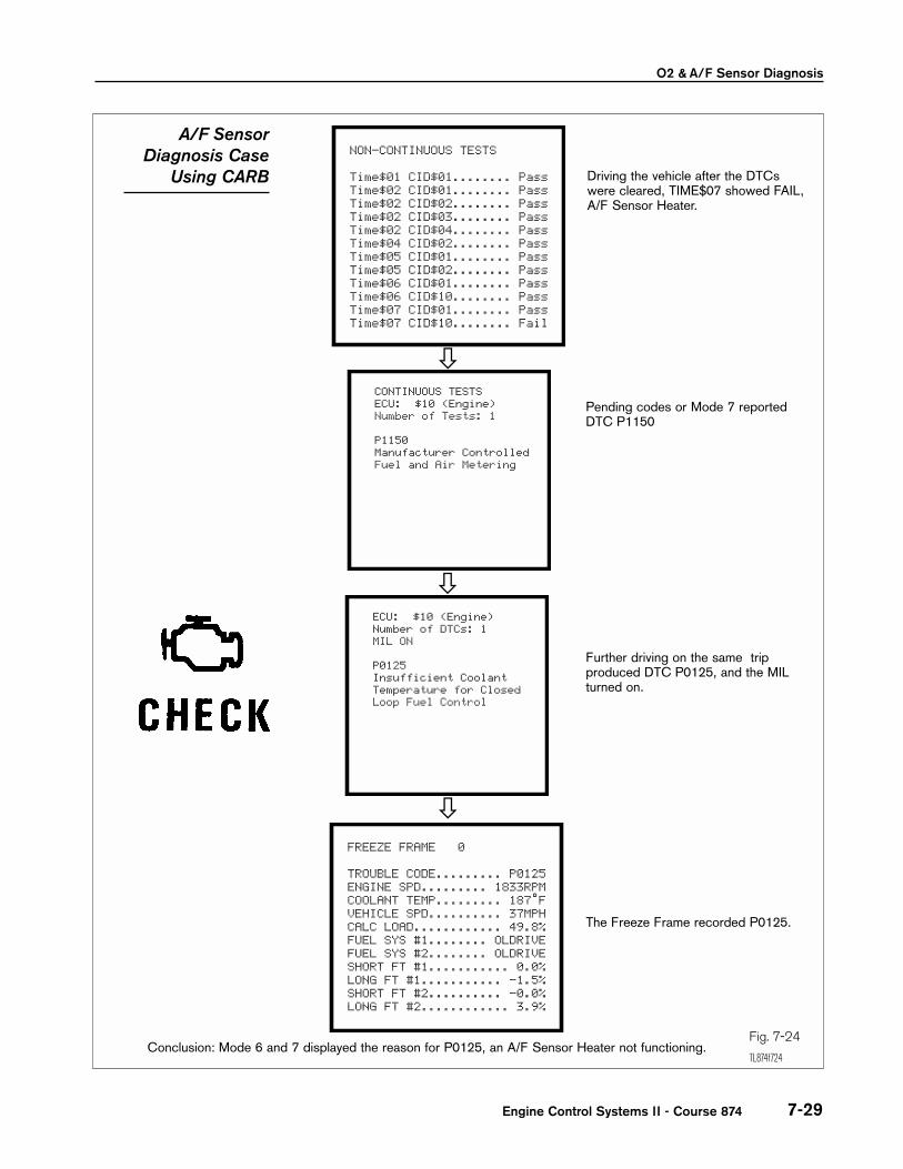
A/F SensorDiagnosis Case
Using CARB
Fig. 7-24
TL874f724
CONTINUOUS TESTS ECU: $10 (Engine) Number of Tests: 1
P1150 Manufacturer Controlled Fuel and Air Metering
ECU: $10 (Engine) Number of DTCs: 1 MIL ON
P0125 Insufficient Coolant Temperature for Closed Loop Fuel Control
FREEZE FRAME 0
TROUBLE CODE......... P0125ENGINE SPD......... 1833RPMCOOLANT TEMP......... 187˚FVEHICLE SPD.......... 37MPHCALC LOAD............ 49.8%FUEL SYS #1........ OLDRIVEFUEL SYS #2........ OLDRIVESHORT FT #1........... 0.0%LONG FT #1........... -1.5%SHORT FT #2.......... -0.0%LONG FT #2............ 3.9%
Driving the vehicle after the DTCswere cleared, TIME$07 showed FAIL,A/F Sensor Heater.
Pending codes or Mode 7 reportedDTC P1150
Further driving on the same tripproduced DTC P0125, and the MILturned on.
The Freeze Frame recorded P0125.
Conclusion: Mode 6 and 7 displayed the reason for P0125, an A/F Sensor Heater not functioning.
NON-CONTINUOUS TESTS
Time$01 CID$01........ PassTime$02 CID$01........ PassTime$02 CID$02........ PassTime$02 CID$03........ PassTime$02 CID$04........ PassTime$04 CID$02........ PassTime$05 CID$01........ PassTime$05 CID$02........ PassTime$06 CID$01........ PassTime$06 CID$10........ PassTime$07 CID$01........ PassTime$07 CID$10........ Fail
TOYOTA Technical Training7-30
Section 7
A/F has lower resistance
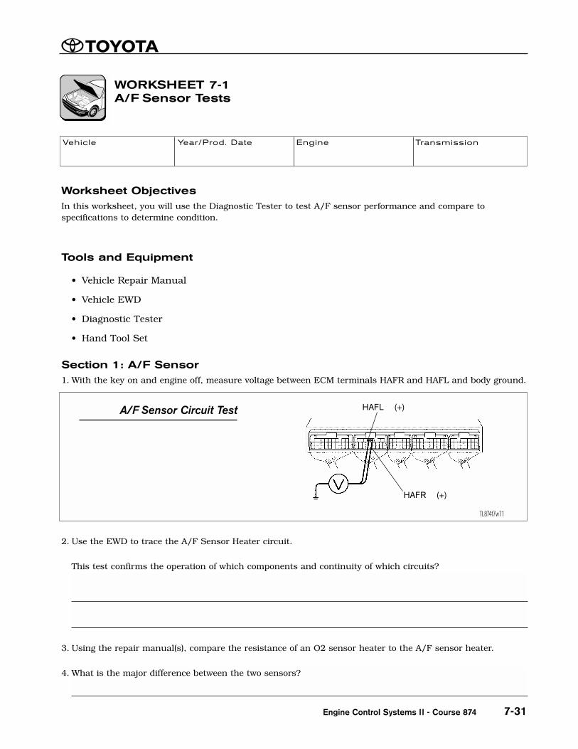
Worksheet ObjectivesIn this worksheet, you will use the Diagnostic Tester to test A/F sensor performance and compare tospecifications to determine condition.
Tools and Equipment
• Vehicle Repair Manual
• Vehicle EWD
• Diagnostic Tester
• Hand Tool Set
Section 1: A/F Sensor1. With the key on and engine off, measure voltage between ECM terminals HAFR and HAFL and body ground.
2. Use the EWD to trace the A/F Sensor Heater circuit.
This test confirms the operation of which components and continuity of which circuits?
3. Using the repair manual(s), compare the resistance of an O2 sensor heater to the A/F sensor heater.
4. What is the major difference between the two sensors?
WORKSHEET 7-1A/F Sensor Tests
Vehicle Year/Prod. Date Engine Transmission
Engine Control Systems II - Course 874 7-31
(Instructors’ Copy)
A/F Sensor Circuit Test
TL874f7w71
HAFL (+)
HAFR (+)
The A/F Heater, Heater Relay, and heater circuit.

Worksheet 7-1
TOYOTA Technical Training7-32
Section 2: A/F Sensor ResponseConnect the Diagnostic Tester. With the engine at operating temperature, go to DATA LIST, USER DATA andselect one of the A/F sensors, SHORT TERM FUEL TRIM, and select ENTER. Select F4. With a set of jumperleads, connect a Fluke 87 (or comparable) DVOM in series with the A/F signal wire. Make sure, the + lead isin the milliamp socket.
1. Record A/F sensor engine idling. Briefly, snap the throttle wide open and release. What happened?
2. Disconnect a vacuum hose. Was there a change to A/F voltage signal and Short Term Fuel Trim?
3. Reconnect vacuum hose.
4. Predict what will happen to A/F signal voltage and amperage if more fuel is added?
5. Go to INJECTOR VOLUME ACTIVE TEST. Increase injector duration. What happened to A/F sensor voltageand amperage signal?
6. Decrease injector duration. What happened to A/F sensor signal voltage amperage?
Test or confirm repair method using CARB OBD II Readiness Tests.
1. Access READINESS TEST Mode under CARB OBD II. What does it report?
Voltage change up & down
Yes
Voltage will go down
Voltage goes down
Voltage goes up
It reports monitor status

A/F Sensor Tests
7-33
Case 1After DTCs were cleared, an A/F sensor equipped vehicle was driven one trip according to the drive pattern.Answer the following questions using the listed screen prints.
2. Do the screens indicate a problem with the vehicle?
3. What area(s) is affected?
4. Will there be DTC(s) and Freeze Frame?
Engine Control Systems II - Course 874
TL874f7w71
READINESS TEST
MISFIRE MON.......... AVAILFUEL SYS MON......... AVAILCOMP MON............. AVAILCAT EVAL............. COMPLHTD CAT EVAL........... N/AEVAP EVAL........... INCMPL2nd AIR EVAL........... N/AA/C EVAL............... N/AO2S EVAL............ INCMPLO2S HTR EVAL........ INCMPLEGR EVAL............. COMPL
NON-CONTINUOUS TESTS
Time$01 CID$01........ PassTime$02 CID$01........ PassTime$02 CID$02........ PassTime$02 CID$03........ PassTime$02 CID$04........ PassTime$04 CID$02........ PassTime$05 CID$01........ PassTime$05 CID$02........ PassTime$06 CID$01........ PassTime$06 CID$10........ PassTime$07 CID$01........ PassTime$07 CID$10........ Pass
The A/F Sensor and heater evaluations have not been determined.
Inconclusive
No

Worksheet 7-1
TOYOTA Technical Training7-34
Case 2An A/F sensor equipped vehicle was driven after DTCs were cleared. Answer the questions from the followingscreens.
1. Do the screens indicate a problem with the vehicle?
2. What area(s) is affected?
3. Will there be DTC(s) and Freeze Frame?
The O2 (A/F) HTR did run and failed. The A/F Sensor monitor evaluation has not been determined.
TL874f7w71
READINESS TEST
MISFIRE MON.......... AVAILFUEL SYS MON......... AVAILCOMP MON............. AVAILCAT EVAL............ INCMPLHTD CAT EVAL........... N/AEVAP EVAL........... INCMPL2nd AIR EVAL........... N/AA/C EVAL............... N/AO2S EVAL............ INCMPLO2S HTR EVAL........ INCMPLEGR EVAL............ INCMPL
NON-CONTINUOUS TESTS
Time$01 CID$01........ PassTime$02 CID$01........ PassTime$02 CID$02........ PassTime$02 CID$03........ PassTime$02 CID$04........ PassTime$04 CID$02........ PassTime$05 CID$01........ PassTime$05 CID$02........ PassTime$06 CID$01........ PassTime$06 CID$10........ PassTime$07 CID$01........ PassTime$07 CID$10........ Fail
A/F heater circuit.
Not on the first trip for heater, but P0125 will set if driven properly.
A/F Sensor Tests
7-35
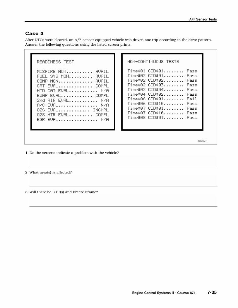
Case 3After DTCs were cleared, an A/F sensor equipped vehicle was driven one trip according to the drive pattern.Answer the following questions using the listed screen prints.
1. Do the screens indicate a problem with the vehicle?
2. What area(s) is affected?
3. Will there be DTC(s) and Freeze Frame?
Engine Control Systems II - Course 874
TL874f7w71
READINESS TEST
MISFIRE MON.......... AVAILFUEL SYS MON......... AVAILCOMP MON............. AVAILCAT EVAL............. COMPLHTD CAT EVAL........... N/AEVAP EVAL............ COMPL2nd AIR EVAL........... N/AA/C EVAL............... N/AO2S EVAL............ INCMPLO2S HTR EVAL......... COMPLEGR EVAL............... N/A
NON-CONTINUOUS TESTS
Time$01 CID$01........ PassTime$02 CID$01........ PassTime$02 CID$02........ PassTime$02 CID$03........ PassTime$02 CID$04........ PassTime$04 CID$02........ PassTime$06 CID$01........ FailTime$06 CID$10........ PassTime$07 CID$01........ PassTime$07 CID$10........ PassTime$08 CID$01........ Pass
Problem with an A/F Sensor
The A/F Sensor, circuit or some problem that can cause the A/F Sensor not to properly respond.
Not on the first trip unless the condition is severe enough to set DTC P0125. Pending DTC can be seen.

Worksheet 7-1
TOYOTA Technical Training7-36
Case 4After DTCs were cleared, an A/F sensor equipped vehicle was driven one trip according to the drive pattern.The MIL illuminated. Answer the following questions using the listed screen prints.
1. Do the screens indicate a problem with the vehicle?
2. What area(s) is affected?
3. Will there be more DTC(s) on the second trip if driven according to the drive pattern?
Yes, the problem is in the heater circuit.
A/F heater circuit
Yes, A/F Heater DTC, if it is a two trip heater DTC.
TL874f7w71
FREEZE FRAME 0
TROUBLE CODE......... P0125ENGINE SPD......... 1833RPMCOOLANT TEMP......... 187˚FVEHICLE SPD.......... 37MPHCALC LOAD............ 49.8%FUEL SYS #1........ OLDRIVEFUEL SYS #2........ OLDRIVESHORT FT #1........... 0.0%LONG FT #1........... -1.5%SHORT FT #2........... 0.0%LONG FT #2............ 3.9%
NON-CONTINUOUS TESTS
Time$01 CID$01........ PassTime$02 CID$01........ PassTime$02 CID$02........ PassTime$02 CID$03........ PassTime$02 CID$04........ PassTime$04 CID$02........ PassTime$05 CID$01........ PassTime$05 CID$02........ PassTime$06 CID$01........ PassTime$06 CID$10........ PassTime$07 CID$01........ PassTime$07 CID$10........ Fail

A/F Sensor Tests
Name: __________________________________________________________ Date: _________________________
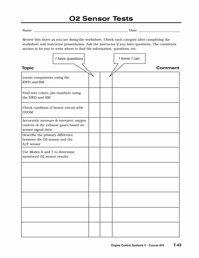
Review this sheet as you are doing the worksheet. Check each category after completing theworksheet and instructor presentation. Ask the instructor if you have questions. The commentssection is for you to write where to find the information, questions, etc.
I have questions I know I can
Topic Comment
Locate components using the EWD and RM
Find wire colors, pin numbers usingthe EWD and RM
Check condition of heater circuit withDVOM
Accurately measure & interpret; oxygencontent of the exhaust gases based onsensor signal data
Describe the primary differencebetween the O2 sensor and the A/F sensor
Use Modes 6 and 7 to determinemonitored A/F sensor results
Measure A/F sensor signal with DVOMand determine engine operatingconditions
Engine Control Systems II - Course 874 7-37
TOYOTA Technical Training7-38
Worksheet 7-1

Worksheet ObjectivesIn this worksheet, you will use the Diagnostic Tester and to check and test O2 sensor monitor performanceand determine needed action.
Tools and Equipment
• Vehicle Repair Manual
• Vehicle EWD
• Diagnostic Tester
• Hand Tool Set
Case 1Answer the following from the screen shots. The O2 sensor equipped vehicle was driven after clearing DTCs.
1. What is the status of the O2S monitor and O2S HTR heater monitor?
2. What does the Readiness Test indicate?
WORKSHEET 7-2O2 Sensor Test
Vehicle Year/Prod. Date Engine Transmission
Engine Control Systems II - Course 874 7-39
(Instructors’ Copy)
TL874f7w72
READINESS TEST
MISFIRE MON.......... AVAILFUEL SYS MON......... AVAILCOMP MON............. AVAILCAT EVAL............ INCMPLHTD CAT EVAL........... N/AEVAP EVAL........... INCMPL2nd AIR EVAL........... N/AA/C EVAL............... N/AO2S EVAL............ INCMPLO2S HTR EVAL........ INCMPLEGR EVAL............... N/A
NON-CONTINUOUS TESTS
Time$01 CID$01........ PassTime$01 CID$02........ PassTime$02 CID$01........ PassTime$02 CID$02........ PassTime$02 CID$03........ PassTime$02 CID$04........ PassTime$04 CID$01........ PassTime$04 CID$02........ PassTime$04 CID$10........ PassTime$04 CID$20........ Pass
Inconclusive, no determination
Indicates the status of the monitors
Worksheet 7-2
TOYOTA Technical Training7-40
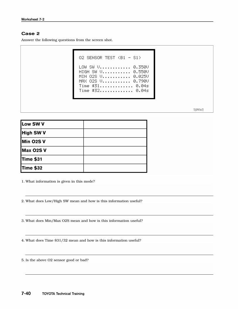
Case 2 Answer the following questions from the screen shot.
1. What information is given in this mode?
2. What does Low/High SW mean and how is this information useful?
3. What does Min/Max O2S mean and how is this information useful?
4. What does Time $31/32 mean and how is this information useful?
5. Is the above O2 sensor good or bad?
TL874f7w72
O2 SENSOR TEST (B1 - S1)
LOW SW V............ 0.350VHIGH SW V........... 0.550VMIN O2S V........... 0.025VMAX O2S V........... 0.790VTime $31............. 0.04sTime $32............. 0.04s
Low SW V
High SW V
Min O2S V
Max O2S V
Time $31
Time $32
If the O2S monitor ran, and the sensor response.
Low and high sensor voltage parameter for switch time calculations.
The minimum and maximum sensor voltage during monitor operations.
The time the sensor crosses the high/low points. Indicates response.
Good
O2 Sensor Tests
7-41Engine Control Systems II - Course 874
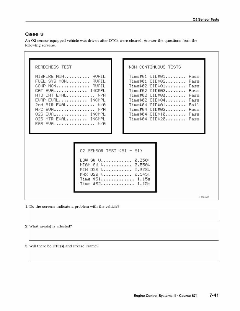
Case 3An O2 sensor equipped vehicle was driven after DTCs were cleared. Answer the questions from the following screens.
1. Do the screens indicate a problem with the vehicle?
2. What area(s) is affected?
3. Will there be DTC(s) and Freeze Frame?
TL874f7w72
READINESS TEST
MISFIRE MON.......... AVAILFUEL SYS MON......... AVAILCOMP MON............. AVAILCAT EVAL............ INCMPLHTD CAT EVAL........... N/AEVAP EVAL........... INCMPL2nd AIR EVAL........... N/AA/C EVAL............... N/AO2S EVAL............ INCMPLO2S HTR EVAL........ INCMPLEGR EVAL............... N/A
NON-CONTINUOUS TESTS
Time$01 CID$01........ PassTime$01 CID$02........ PassTime$02 CID$01........ PassTime$02 CID$02........ PassTime$02 CID$03........ PassTime$02 CID$04........ PassTime$04 CID$01........ FailTime$04 CID$02........ PassTime$04 CID$10........ PassTime$04 CID$20........ Pass
The O2 HTR did run and failed. For O2S EVAL, O2S Test Results indicate poor resp.onse
O2 heater circuit.
Not on the first trip for heater, but P0125 will set if driven properly.
O2 SENSOR TEST (B1 - S1)
LOW SW V............ 0.350VHIGH SW V........... 0.550VMIN O2S V........... 0.378VMAX O2S V........... 0.545VTime $31............. 1.15sTime $32............. 1.15s

Worksheet 7-2
TOYOTA Technical Training7-42
Section 4: O2 Sensor Response1. With the engine at operating temperature, go to Data List and note the O2 sensor voltage signal and Fuel
Trim. Disconnect a vacuum hose. Was there a change to oxygen voltage signal and Short Term Fuel Trim?
2. Reconnect vacuum hose.
3. Predict what will happen to O2 sensor signal voltage if more fuel is added?
4. Go to Injector Volume Active test. Add fuel using the Active Test to increase injector duration. Whathappened to O2 sensor voltage signal?
5. Decrease injector duration. What happened to O2 sensor signal voltage?
Yes
Voltage will go up.
Voltage went up.
Voltage went down.
O2 Sensor Tests
Name: __________________________________________________________ Date: _________________________
Review this sheet as you are doing the worksheet. Check each category after completing theworksheet and instructor presentation. Ask the instructor if you have questions. The commentssection is for you to write where to find the information, questions, etc.
I have questions I know I can
Topic Comment
Locate components using the EWD and RM
Find wire colors, pin numbers usingthe EWD and RM
Check condition of heater circuit withDVOM
Accurately measure & interpret; oxygencontent of the exhaust gases based onsensor signal data
Describe the primary differencebetween the O2 sensor and the A/F sensor
Use Modes 6 and 7 to determinemonitored O2 sensor results
Engine Control Systems II - Course 874 7-43


![O2 Czech Republic · O2 Czech Republic Group structure 4 Slovakia TV Family Other [1] [1] O2 CR branch in Slovakia,Tesco Mobile CR, Internethome, O2 IT Services, ICA Group ... “Breaking](https://static.fdocuments.in/doc/165x107/5f4e4a1ecad616584844602e/o2-czech-republic-o2-czech-republic-group-structure-4-slovakia-tv-family-other-1.jpg)