Section 7 Existing Treatment Facilities · 2016-03-21 · Section 7 Existing Treatment Facilities...
92
7-1 V1 Section 7.doc Facilities Plan Volume 1: Wastewater Management Section 7 Existing Treatment Facilities 7.1 Introduction An essential tool for the IRP is the wastewater treatment and effluent discharge facility capacities. There are six wastewater treatment facilities within the City’s service area. Five treatment plants are within the HSA as follows: Hyperion Treatment Plant (HTP) in Playa del Rey. Donald C. Tillman Water Reclamation Plant (TWRP) in the Sepulveda Basin in Van Nuys. Los Angeles-Glendale Water Reclamation Plant (LAGWRP) across the Golden State freeway from Griffith Park. Burbank Water Reclamation Plant (BWRP) in the City of Burbank. Los Angeles Zoo Treatment Facility (LAZTF) in Griffith Park. The sixth treatment plant, TITP, serves the TISA and is in the vicinity of the Los Angeles Harbor. The locations of the HTP, TWRP, LAGWRP, and TITP are shown in Figure 3-1 of Section 3. The HSA includes three plants operated by the City of Los Angeles: TWRP, LAGWRP and HTP. The TWRP treats flows from the San Fernando Valley. The LAGWRP serves the Glendale/Burbank area and can treat excess flows that by-pass the TWRP. The HTP serves the central Los Angeles area, treats excess flows from the San Fernando Valley and Glendale/Burbank area, and processes solids from the TWRP, LAGWRP, BWRP, and LAZTF. The BWRP is owned and operated by the City of Burbank and the Los Angeles Zoo operates its own treatment plant. The TITP serves the TISA, which includes the Los Angeles Harbor, and nearby communities, including San Pedro and Wilmington. This section describes the existing facilities and an evaluation of the current capacity of the unit processes at each plant. Existing capacities are based on results of the planning model discussed in Subsection 7.2. 7.2 Comprehensive Planning Model An important component for this planning effort is the wastewater treatment process simulation model. The purpose of this model is to assist the IRP team with evaluation of existing wastewater treatment capacities; identify process bottlenecks and modifications; assess potential innovative treatment technologies; and evaluate options that provide upstream satellite treatment capabilities.
Transcript of Section 7 Existing Treatment Facilities · 2016-03-21 · Section 7 Existing Treatment Facilities...

7-1
V1 Section 7.doc Facilities Plan Volume 1: Wastewater Management
Section 7 Existing Treatment Facilities 7.1 Introduction An essential tool for the IRP is the wastewater treatment and effluent discharge facility capacities. There are six wastewater treatment facilities within the City’s service area. Five treatment plants are within the HSA as follows:
Hyperion Treatment Plant (HTP) in Playa del Rey.
Donald C. Tillman Water Reclamation Plant (TWRP) in the Sepulveda Basin in Van Nuys.
Los Angeles-Glendale Water Reclamation Plant (LAGWRP) across the Golden State freeway from Griffith Park.
Burbank Water Reclamation Plant (BWRP) in the City of Burbank.
Los Angeles Zoo Treatment Facility (LAZTF) in Griffith Park.
The sixth treatment plant, TITP, serves the TISA and is in the vicinity of the Los Angeles Harbor. The locations of the HTP, TWRP, LAGWRP, and TITP are shown in Figure 3-1 of Section 3.
The HSA includes three plants operated by the City of Los Angeles: TWRP, LAGWRP and HTP. The TWRP treats flows from the San Fernando Valley. The LAGWRP serves the Glendale/Burbank area and can treat excess flows that by-pass the TWRP. The HTP serves the central Los Angeles area, treats excess flows from the San Fernando Valley and Glendale/Burbank area, and processes solids from the TWRP, LAGWRP, BWRP, and LAZTF.
The BWRP is owned and operated by the City of Burbank and the Los Angeles Zoo operates its own treatment plant. The TITP serves the TISA, which includes the Los Angeles Harbor, and nearby communities, including San Pedro and Wilmington.
This section describes the existing facilities and an evaluation of the current capacity of the unit processes at each plant. Existing capacities are based on results of the planning model discussed in Subsection 7.2.
7.2 Comprehensive Planning Model An important component for this planning effort is the wastewater treatment process simulation model. The purpose of this model is to assist the IRP team with evaluation of existing wastewater treatment capacities; identify process bottlenecks and modifications; assess potential innovative treatment technologies; and evaluate options that provide upstream satellite treatment capabilities.

Section 7 Integrated Resources Plan Existing Treatment Facilities
7-2 Facilities Plan V1 Section 7.doc Volume 1: Wastewater Management
There are various software packages available for this type of analysis. The IRP team selected PRO2D and BioWin, developed by CH2M HILL and EnviroSim Associates LTD, respectively. These models are industry-accepted for design and analysis of wastewater treatment plants.
PRO2D is a steady-state simulation tool that allows engineers to simulate the behavior of existing facilities, modify existing facilities with a new process, or design a new wastewater treatment plant (including emerging treatment processes such as membrane bioreactors). PRO2D performs a mass balance over the entire treatment plant and projects the impacts of changes made to the plant in terms of both effluent quality and solids handling requirements. Additionally, the program is designed so that typical measurements collected at wastewater treatment plants [such as biochemical oxygen demand (BOD) and total suspended solids (TSS)] can be converted automatically into wastewater characteristics as required for simulation of biological processes. PRO2D offers the benefits of speed, ease of use, ease of calibration, and a proven track record.
BioWin provides a powerful dynamic process simulation tool and a more comprehensive graphical output. It is useful in evaluating many of the time-dependent variables at a wastewater treatment plant. This feature is particularly useful for assessing biological processes. The graphical interface and outputs provide quick access to detailed modeling results.
For the IRP, PRO2D and BioWin were linked together to permit a seamless analysis of a particular treatment plant alternative configuration. The ability to link PRO2D with BioWin was primarily used to further refine planning and design decisions, especially when modeling significantly variable wastewater loads or storm events to a plant.
For each of the City-owned wastewater treatment facilities, the PRO2D and BioWin models were first configured to simulate the current treatment processes. Next, process data for the previous year was then collected and analyzed for inconsistencies. Current operational procedures were then identified and confirmed within each plant. Lastly, the operational information and process data were used to configure and calibrate the model.
The initial model output results for each plant’s performance were compared to actual field data, and appropriate model calibrations were made to simulate, to the maximum extent possible, current plant performance.
Using the calibrated models, future flow and loading conditions were applied to confirm process bottlenecks and the need for additional facilities as discussed further in Subsections 7.3 through 7.6 of this report.

Integrated Resources Plan Section 7 Existing Treatment Facilities
7-3
V1 Section 7.doc Facilities Plan Volume 1: Wastewater Management
7.3 Hyperion Treatment Plant (HTP) Located adjacent to Los Angeles World Airport in the beach community of Playa Del Rey, HTP is the City’s oldest and largest wastewater treatment facility, and has been operating since the early 1890's. Initially built as a raw sewage discharge point into the Santa Monica Bay, it has been upgraded over the years to advanced primary/partial secondary treatment (1950), and most recently to full secondary treatment (1998).
The HTP is located on a 144-acre site adjacent to the Pacific Ocean. The plant is bounded on the north by Imperial Highway, on the west by Vista Del Mar, on the south by the Scattergood Power Plant, and on the east by the City of El Segundo.
The HSA covers about 600-square miles total, including contract agencies outside of the City and roughly 90 percent of the 465-square miles within the City limits. Located in the south portion of the HSA, HTP serves many communities directly including: Baldwin Hills, Bel Air-Beverly Crest, Beverly Hills, Brentwood, Boyle Heights, Central City North, Central City, Central Los Angeles, Culver City, Echo Park, Hollywood, Marina Del Rey, Northeast Los Angeles, Pacific Palisades, Palms, Playa del Rey, Sherman Oaks, Silverlake, Southeast Los Angeles, Studio City, Universal City, West Adams, Westchester, Westlake, West Los Angeles, Westwood, and Wilshire. The area tributary to HTP is shown in Figure 4-1 of Section 4.
In addition to these communities, HTP treats flows that are bypassed from the TWRP and the LAGWRP. HTP also provides centralized solids handling and processing for the entire HSA, including also solids from the LAZTF and the BWRP. Raw wastewater enters the HTP through the CIS, NCOS, NORS, and COS (see Figure 5-2 of Section 5).
7.3.1 HTP Existing Facilities Introduction There are two components to this section. First is a description of the existing unit processes, important operational procedures, and planning values. Second is an evaluation of the existing unit process treatment and hydraulic capacities at HTP (see Subsection 7.3.8).
The HTP is a full-secondary, high-purity-oxygen, activated sludge treatment plant with unchlorinated ocean discharge. Biosolids removed during treatment of the wastewater are treated by anaerobic digestion, and are then dewatered and trucked offsite for use through a diversified management plan utilizing 100 percent beneficial use. Figure 7-1 presents the HTP site plan and Figure 7-2 shows the process flow diagram.
The HTP is an end-of-the-line plant, subject to diurnal and seasonal flow variation. It was designed to provide full secondary treatment for a maximum-month flow of 450 mgd [which corresponds to an ADWF of 413 mgd] and peak PWWF of 850 mgd. The maximum-month flow design basis was derived in the last published Wastewater Facilities Plan (DMJM/BV, 1990).

Figure 7-1Hyperion Treatment Plant Site Plan

Figure 7-2Hyperion Treatment Plant Process Flow Diagram

Section 7 Integrated Resources Plan Existing Treatment Facilities
7-6 Facilities Plan V1 Section 7.doc Volume 1: Wastewater Management
The design parameters for the influent TSS and BOD concentrations are 302 mg/L and 380 mg/L, respectively. The total design influent maximum month flowrate of 450 mgd is comprised of an influent flowrate of 446 mgd of raw wastewater plus approximately 4 mgd from the dewatering centrate. The corresponding TSS and BOD loadings are 1,240,000 lbs/d and 1,470,000 lbs/d, respectively (Hyperion Full Secondary Design Concept and Implementation Report, DMJM/BV, December 1993). Table 7-1 summarizes the average influent flows and characteristics during the period from June 2001 to July 2002.
Table 7-1 HTP Average Influent Flow and Characteristics From June 2001 to July 2002
Description Current, June 2001 to July
2002, Values* Projected 2020 Values (see also
Subsection 4.5) Average Flow (ADWF) 340 mgd 435 mgd** Peak Flow 490 mgd Average BOD 325 mg/L 293 mg/L Average TSS 410 mg/L 337 mg/L Source: Monthly Performance Reports July 2001 to June 2002 Notes: * Historically over the last 10 years the TSS has averaged about 350 mg/L and the BOD has averaged about 300 mg/L (see Subsection 4.5). ** Sample flow only. Actual projected flow varies depending on the Alternative.
The HTP provides preliminary, primary, secondary, and solids handling facilities. The basic unit processes include:
Preliminary Treatment: Flow metering, screening, grit removal.
Primary Treatment: Flow metering, primary sedimentation, and raw sludge and scum removal and conveyance.
Secondary Treatment: Intermediate pump station, oxygen reactors, oxygen generation and storage, final sedimentation, return activated sludge (RAS) and waste activated sludge (WAS) piping, and WAS thickening.
Effluent Discharge System: Effluent pumping plant, one-mile emergency outfall, five-mile outfall, emergency storage facility and by-pass channels from primary clarifiers to effluent discharge system.
Solids Handling and Treatment: WAS thickening, anaerobic digesters, sludge screening, sludge dewatering, dewatered sludge storage and truck loading facility, and digester gas handling.

Integrated Resources Plan Section 7 Existing Treatment Facilities
7-7
V1 Section 7.doc Facilities Plan Volume 1: Wastewater Management
7.3.2 HTP Preliminary Treatment Preliminary treatment protects subsequent plant processes by removing materials that can clog and damage equipment, cause excessive wear, or reduce treatment efficiency.
7.3.2.1 Screening At the HTP, the headworks consist of 8 mechanically cleaned bar screens (five duty, three standby), which are in place with provisions for the installation of two additional screens for ultimate expansion. The barscreens are designed for a peak wet weather flow of 800 mgd, but historical performance has shown that they can accommodate up to about 1,100 mgd. Two additional channels are in place for the installation of two additional screens in the future. Screenings are transported by a sluiceway, shredded, and pumped to rotating drum screens for dewatering. The dewatered screenings are compacted and hauled by truck to a landfill.
7.3.2.2 Grit Removal Grit removal at the HTP is accomplished by 6 aerated grit basins. The design capacity of each is 167 mgd (1,000 mgd total). However, they can hydraulically handle flows in excess of 1,100 mgd. The accumulated grit is pumped to cyclones and classifiers for washing and dewatering prior to hauling to a landfill for disposal. At the south end of the grit chambers is a splitter structure to direct flow to the primary clarifiers. Table 7-2 summarizes the HTP's preliminary treatment facilities.
Table 7-2 HTP Existing Preliminary Treatment Facilities
Unit Value Screenings Removal Type Mechanically Raked Number 8 + (2 slots for future units) Width 10 ft Design Capacity 100 mgd each Grit Basins Type Aerated Number 6 Volume, each 22.5 ft x 150 ft x 15 ft deep Sidewater Depth 15 ft Design Flow 1,000 mgd Sources: :Hyperion Full Secondary Design Concept and Implementation Report, DMJM/BV, December 1993 Meetings and discussions with City Staff

Section 7 Integrated Resources Plan Existing Treatment Facilities
7-8 Facilities Plan V1 Section 7.doc Volume 1: Wastewater Management
One important note, the flow from the CIS has a higher saline content than from the other influent sewers. This can upset the total dissolved solids (TDS) levels of the effluent that is sent to the West Basin Water Recycling Facility (WBWRF). To combat this, a gate was installed between the bar screens and the aerated grit chambers to help divert flow from CIS to Primary Battery A and to Secondary Reactor Module 9. Since the primary source of flow for WBWRF comes from Secondary Reactors 1 and 2, this diversion setting has helped to improve the quality of secondary effluent delivered to WBWRF.
7.3.3 HTP Primary Treatment The primary treatment process removes the majority of the settleable organic and inorganic materials that enter the plant. Floatable material is removed by surface skimming. These functions significantly reduce the BOD and TSS loadings on the secondary treatment process. Table 7-3 summarizes the HTP's primary treatment facilities.
Table 7-3 HTP Existing Primary Treatment Facilities
Unit Value Primary Clarifiers
Treatment type Enhanced with Ferric Chloride and polymer addition Primary Battery A Number 4
Area 56.5 ft x 300 ft Water Depth 15.1 ft Primary Battery B Number 4
Area 56.5 ft x 300 ft Depth 15.1 ft Number 2 Area 60 ft x 300 ft Depth 15.1 ft Primary Battery C Number 4
Area 56.5 ft x 300 ft Depth 15.1 ft Number 1 Area 60 ft x 300 ft Depth 15.1 ft Primary Battery D Number 12
Area 17.5 ft x 300 ft Depth 15 ft Sources: Hyperion Full Secondary Design Concept and Implementation Report, DMJM/BV, December 1993 Meetings and discussions with City Staff concerning current operation

Integrated Resources Plan Section 7 Existing Treatment Facilities
7-9
V1 Section 7.doc Facilities Plan Volume 1: Wastewater Management
The HTP’s existing primary treatment facilities consist of four batteries of rectangular primary clarifiers: Batteries A through D. Battery A is presently out-of-service due to reconstruction work to raise and replace the top elevation of the tanks and replace the interior components. Reconstruction of Battery A is scheduled to be completed by late 2004. Future plans include similar remodeling of the original clarifiers of Battery B and C.
The number of rectangular clarifiers in each battery varies: Four for Battery A, six for Battery B, five for Battery C, and 12 small ones (equivalent to four large units) for Battery D. The result is the equivalent of 19 large clarifiers. The clarifiers have a total surface area of 327,600 ft2. While designed for a surface overflow rate (SOR) of 1,550 to 1,700 gallons per day per square foot (gpd/ft2), the primary clarifiers (with chemical addition) have historically performed at 80 percent to 85 percent TSS removals with an average SOR in the range of 2,000- 2,400 gpd/ft2. Each of the 1950’s era large primary tanks have been field tested to 75 mgd for maximum hydraulic capacity, while the Battery D tanks have been tested to 25 mgd maximum. The three new primary tanks built in Batteries B and C in 1998 have not been tested to determine maximum capacity. A detailed capacity evaluation of the primary clarifiers is provided in Subsection 7.3.8.
Flow enters each tank through inlet ports from influent channels. Ferric chloride and anionic polymer are added to improve particle settling. Ferric chloride is injected upstream of the headworks and anionic polymer is injected just downstream of the aerated grit chambers. Effluent is collected at the opposite end of each battery in a system of concrete or steel troughs that convey the flow to the primary effluent channels. Primary effluent normally flows to the Intermediate Pump Station (IPS). However, all or part of the primary effluent can be diverted to the Emergency Storage Basins and, if needed, to the Effluent Pumping Plant if the IPS is either not functional or the flow exceeds its capacity.
Sludge from all four batteries is pumped to a primary sludge pump station, from where the sludge is pumped to the digesters. To accommodate different lift requirements, a separate set of four pumps is provided for the conventional 1950 cylindrical digesters and the 1998 modified-egg-shaped digesters. The modified-egg-shaped digesters require higher pumping lift as compared to the conventional cylindrical digesters.
7.3.4 Intermediate Pumping Station (IPS) The IPS includes 10 screw pumps to lift primary effluent to a higher elevation, allowing gravity flow through the secondary treatment process. An emergency generator is provided to supply power to two pumps in case of a power outage. Although designed to provide 125 mgd each, or a total of 1,125 mgd with nine pumps in service, plant operations staff have reported reduced capacities of 100 to 115 mgd. Table 7-4 summarizes the IPSs existing facilities.

Section 7 Integrated Resources Plan Existing Treatment Facilities
7-10 Facilities Plan V1 Section 7.doc Volume 1: Wastewater Management
Table 7-4 HTP Intermediate Pumping Station
Unit Value Type Screw pump Number 8 duty, 1 standby, 1 maintenance Diameter 150 inch Capacity, each 100 mgd Sources: Hyperion Full Secondary Design Concept and Implementation Report, DMJM/BV, December 1993 Meetings and discussions with City Staff concerning current operation
7.3.5 HTP Secondary Treatment The HTP’s secondary treatment process facilities include high-purity oxygen treatment units arranged in nine treatment modules. Each treatment module consists of an individual influent channel, three high-purity oxygen activated sludge bioreactor trains (oxygen reactors) and four circular secondary clarifiers. Figure 7-3 shows the existing secondary treatment configuration. Table 7-5 provides average monthly values of operational parameters.
Table 7-5 HTP Secondary Treatment Avg. Operational Parameters From June, 2001 to July, 2002
Description Value
Oxygen reactors online 12 trains (spread through the 9 treatment modules)
Mixed liquor suspended solids (MLSS)1 1,520 mg/L Mean cell residence time (MCRT) 1.1 days Oxygen usage 225 tons/day Sludge volume index (SVI) 185 mL/g Return activated sludge (RAS) 103 mgd flow at 6,325 mg/L Waste activated sludge (WAS) 7 mgd flow at 6,275 mg/L
SSource: Monthly Performance Reports July 2001 to June 2002.
Average from aerobic and anaerobic selector oxygen reactors
7.3.5.1 Oxygen Reactors Primary effluent from the IPS is discharged to nine secondary reactor influent channels. For each treatment module, the primary effluent first enters a chamber where it is mixed with the RAS. The mixture flows over a weir to a distribution chamber, which controls the flow to each of the oxygen reactors (see Figure 7-4). Each module contains three oxygen reactors, for a total of 27 oxygen reactors. During design, provisions were made so that two additional modules could be added at a later date, which would increase the total number of oxygen reactors to 33. The reactors are covered to prevent the loss of oxygen to the atmosphere within the first cell.

Figure 7-3Hyperion Treatment Plan Secondary Treatment

Figure 7-4Hyperion Treatment Plant Secondary Treatment
Configuration

Integrated Resources Plan Section 7 Existing Treatment Facilities
7-13
V1 Section 7.doc Facilities Plan Volume 1: Wastewater Management
Each of the 27 oxygen reactors is divided into five equally sized mixing cells (see Figure 7-5). To improve the settling of the oxygen reactor effluent in the secondary clarifiers, Modules 3 and 5 have been converted to have anaerobic selectors. The improved settling is a result of the control of filamentous bacteria that this configuration provides. The remaining modules still contain the original configuration. However, future plans include possibly converting all or part of the remaining oxygen reactors to the anaerobic selectors.
In the aerobic selectors (original design), the first two cells are each mixed with 125-hp aerators. High-purity oxygen is diffused into the mixed liquor in the first two cells of each reactor to meet the oxygen demands. To equalize the oxygen uptake rate, no separation wall is provided between the first two cells.
For the anaerobic selectors (modified design), the first two cells are still mixed, with a 45-hp mixer in the first cell and a 125-hp mixer in the second cell. However, a separation wall was constructed between these cells. No oxygen is added within the first cell. For all reactors, the last three mixing cells are separated by concrete partition walls and are equipped with 75-hp aerators.
According to the plant operations staff, the present BOD loading to the oxygen reactors is lower than anticipated in the 2010 Facility Plan due to lower than predicted BOD concentration of the influent wastewater, and addition of ferric chloride and polymer in the primary clarifiers, resulting in enhanced BOD removal. In addition, operation of the oxygen reactors with the anaerobic selectors allows for an increased loading to the reactors. As a result, the oxygen reactors have excess capacity, and can accommodate flows well in excess of the design basis maximum monthly flow of 450 mgd. A detailed evaluation of HTP's secondary treatment unit process capacities is presented in Subsection 7.3.8.
7.3.5.2 Oxygen System Pure oxygen for the oxygen reactors is generated in a cryogenic air separation plant at HTP. The cryogenic air separation plant is located east of G Street. The compressor building between Treatment Modules 7 and 8 houses five compressors (plus an equipment pad for one future unit) and associated electrical equipment for the cryogenic facility. Three operating compressors, each rated at 100 percent of the design capacity of a single distillation column, supplies process air. Each compressor is capable of providing a variable air supply ranging between 60 and 100 percent of its rated capacity. Note that only one of these compressors is currently in use.

Figure 7-5Hyperion Treatment Plant
Selector and Conventional Reactor Configuration

Integrated Resources Plan Section 7 Existing Treatment Facilities
7-15
V1 Section 7.doc Facilities Plan Volume 1: Wastewater Management
The compressed air is filtered through molecular sieve absorbers to remove impurities prior to distillation. A small portion of the filtered air is diverted to the plant instrument air system for use by instruments throughout the plant and for the purging of control panel enclosures. The remaining compressed air is introduced into the cryogenic air separation process. There are three distillation columns, each with a production capacity of 240 tons per day (tpd) of high purity oxygen. The columns are equipped with a variable oxygen supply feature, allowing greater flexibility in oxygen production to efficiently meet the seasonal and diurnal demands of the reactor modules. Under maximum month conditions, the design parameters require a production rate of approximately 660 tpd of high purity oxygen. Approximately 866 tpd of high purity oxygen is required under design year peak daily flow conditions, which can be accommodated by the normal operation of this system.
High purity nitrogen, produced by the air separation system, is contained, dried, and stored for in-plant use, such as purging the digester. Use of spent nitrogen for this purpose eliminates the previous practice of purchasing nitrogen. A large portion of the high purity nitrogen is used to cool the incoming air and in the liquefaction process of the cold box. Nitrogen not used at the plant is used to cool incoming process air and then discharged to the atmosphere.
7.3.5.3 Secondary Clarifiers Each of the nine secondary treatment modules has four 150-foot diameter secondary clarifiers, for a total of 36 circular secondary clarifiers at the HTP. Each set of four secondary clarifiers receives the mixed liquor flow from a dedicated oxygen reactor module. During design, provisions were made to add two modules (eight total) of secondary clarifiers in the future.
The clarifiers are of the center inlet type with a large diameter inlet baffle to provide full dissipation of the energy of the mixed liquor entering the clarifier. The inlet area also serves as a low velocity gradient mixing zone to enhance flocculation. In addition, provisions were provided to add polymer in the mixing zone to enhance flocculation pending pilot testing to determine feasibility. Note that side baffles were added to the clarifiers due to hydraulic capacity and velocity concerns.
The settled sludge is continuously removed from the bottom of the clarifiers. A majority of the sludge settled in the secondary clarifiers is pumped back to the oxygen reactors influent channel as RAS. RAS pumping rates are adjusted to maintain a desired blanket target in the secondary clarifiers. A smaller portion of these solids is transferred to the solids handling areas as WAS. Table 7-6 summarizes the HTP’s existing secondary treatment facilities.

Section 7 Integrated Resources Plan Existing Treatment Facilities
7-16 Facilities Plan V1 Section 7.doc Volume 1: Wastewater Management
Table 7-6
HTP Existing Secondary Treatment Facilities Unit Value
Oxygen Reactors Type High Purity Oxygen Number of Modules 9 Number of Trains per Module 3 Number of Mixing Cells per Train 5 Size of Mixing Cells 54 ft x 54 ft x 25 ft
Aerators per Train 5 for conventional 3 for selector
Secondary Clarifiers Type Center inlet, Radial Flow Number 36 Diameter 150 ft Side Wall Depth 12 ft Surface Area per Clarifier 17,670 ft2
Sources: Hyperion Full Secondary Design Concept and Implementation Report, DMJM/BV, December 1993 Meetings and discussions with City Staff concerning current operation
7.3.6 HTP Effluent Discharge System 7.3.6.1 Ocean Outfalls The HTP has three ocean outfalls: one-mile, five-mile, and seven-mile. The one-mile outfall was put in operation in 1925, but suffered from leakage problems and was subsequently replaced by a new one-mile outfall in 1951. The one-mile outfall, which is still operational, is a 12-foot-diameter reinforced concrete pipeline that terminates at a depth of 50 feet. The first 1,550 feet of the pipe extending out from the beach is encased in concrete. The remainder of the pipe is supported on concrete pylons. The one-mile outfall's diffuser consists of four bulkhead ports and six side ports.
By the mid-1950s, further clean up of the recreational waters in the Santa Monica Bay was required, making longer outfalls necessary. In response to this need, a five-mile outfall was constructed and put in operation in 1961, becoming the main effluent discharge outfall for HTP. It consists of a main pipe section and two diffuser legs extending in a Y-pattern from the end. The main outfall section is constructed of 12-foot-diameter reinforced concrete pipe ending at a depth of 187 feet. Each section of the diffuser leg measures 4,000 feet in length and is constructed of 102-inch tapering to 72-inch diameter reinforced concrete pipe, and has a discharge port every six feet along each diffuser leg.

Integrated Resources Plan Section 7 Existing Treatment Facilities
7-17
V1 Section 7.doc Facilities Plan Volume 1: Wastewater Management
The one-mile outfall has not normally been in use since the five-mile outfall was placed in service: It is maintained in standby condition in case of an emergency. The National Pollution Discharge Elimination System (NPDES) permit states that the one-mile outfall is only to be used periodically for the discharge of chlorinated secondary effluent during extremely high flows, power failures, stormwater runoff, and to test the operability of the emergency bypass gates.
The seven-mile outfall was constructed as a result of a study, which concluded that pumping sludge to the ocean, and disposing of it at a depth of 320 feet in a submarine canyon would be more economical than continuing to process the digested sludge into fertilizer back in the 1950's. The digested sludge was mixed with secondary effluent, screened to remove floatables, and then discharged to the ocean through the seven-mile outfall. At the time it was constructed, this method of discharge was thought to be environmentally acceptable. This outfall is a 20 in inside diameter steel pipeline, with a cement mortar interior lining and coal tar enamel and gunite outside coating. The seven-mile outfall was permanently taken out of service in November 1987 and alternate methods of sludge reuse were implemented. Table 7-7 summarizes the HTP’s existing effluent discharge facilities.
Table 7-7 HTP Existing Effluent Discharge Facilities
Description Five-Mile Outfall One-Mile Outfall Diameter 144 inches 144 inches Material Precast Concrete Precast Concrete Length 27,539 ft 5,384 ft Discharge Depth (Mean Sea Level) 190 ft 50 ft No. of Diffusers 2 (North & South) 1 Diffuser Diameter 102, 72 inches 144 inches Length of Diffuser 4,000 ft/each 300 ft
Diffuser Ports 83/each 4-bulkhead port 6- side ports
Port Size 6.75 to 8.13 inches diameter 3.25 ft by 1.5 ft (elliptical) Dilution Ratio (per NPDES permit) 84:1 13:1 Sources: Hyperion Full Secondary Design Concept and Implementation Report, DMJM/BV, December 1993 Meetings and discussions with City Staff
7.3.6.2 Effluent Pumping Plant Under normal operating conditions, a portion of the secondary effluent from the secondary clarifiers is pumped to West Basin Water Recycling Facility for treatment and reuse. The remaining secondary effluent is fed to the Effluent Pump Plant (EPP) where it is either pumped or discharged by gravity through the five-mile outfall. Table 7-8 summarizes the existing EPP facilities.

Section 7 Integrated Resources Plan Existing Treatment Facilities
7-18 Facilities Plan V1 Section 7.doc Volume 1: Wastewater Management
Table 7-8
HTP Effluent Pumping Plant Facilities Description Value
Number of Pumps 5 (3 duty, 2 standby) Type Variable Speed Centrifugal Motor Horsepower, each 2,500 HP Maximum Capacity at 64 Feet TDH, each 180 mgd Sources: Hyperion Full Secondary Design Concept and Implementation Report, DMJM/BV, December 1993 Meetings and discussions with City Staff
According to research by City personnel, the projected pumped capacity of the five-mile outfall is 720 mgd with four of the five pumps in operation. This is for a tide level of +4.2 feet Mean Sea Level (MSL) with an EPP wet well level of 27.0 feet. See Subsection 7.3.8 for the detailed discussion of outfall capacities.
Flows exceeding the pumping capacity would have to be discharged by gravity through the one-mile outfall. In case of a pump or power failure, all flows exceeding the gravity capacity of the five-mile outfall would have to be discharged through the one-mile outfall.
The current NPDES permit (CA0109991) lists the dilution ratios for the 5-mile and 1-mile outfalls as 84:1 and 13:1, respectively. Effluent limitations provided by this permit are based on these ratios. The permit expired in March 1999 and a new permit is pending. The City has recently completed a study to re-evaluate the outfall dilution ratios, and has determined that the dilution ratio for the 5-mile outfall is actually 95:1. Table 7-9 summarizes the HTP’s existing pumped and gravity ocean outfall capacities (see also Subsection 7.3.8).
Table 7-9 HTP Existing Ocean Outfall Capacities (mgd)
Flow Condition1 Five-Mile Outfall2 One-Mile Outfall3 Total capacity
Gravity only 350 727 1,077 4 Pumps + One-Mile Gravity 720 727 1,447 Notes: 1 The gravity capacity is determined at 4.2 feet mean-sea-level (MSL) tide provided the diffuser ports are cleaned properly. A friction factor n = 0.015 is used for both outfalls.
2 An 18-inch brine line from the reverse osmosis process at the West Basin Water Reclamation Plant discharges into the HTP five-mile outfall. The ultimate flow from this line is 3.5 mgd and is considered insignificant to the capacity of the outfall.
3 NPDES permit states that the one-mile outfall is only to be used periodically for the discharge of chlorinated secondary effluent during extremely high flows, power failures, and stormwater runoff. Results are for the cleaned 1mile outfall and diffuser condition.
Integrated Resources Plan Section 7 Existing Treatment Facilities
7-19
V1 Section 7.doc Facilities Plan Volume 1: Wastewater Management
Several alternatives for increasing the outfall capacities were developed in the Draft Final Concept/Predesign Report for the One & Five Mile Outfall Modifications (City, September 1999). Some of the options are:
Cleaning the outfalls
Replacement of the existing diffusers
Construction of another diffuser leg on the 5-mile outfall
Construction of a new outfall
Friction-reducing polymer addition for use during intermittent peak wet weather flows
7.3.7 Solids Handling and Treatment The HTP provides solids treatment for all solids generated in the HSA including those from TWRP and LAGWRP. At the HTP, solids processing presently consists of grit and screenings removal, WAS thickening, anaerobic digestion of the combined primary and secondary sludge, dewatering, and reuse. Note that the City is currently evaluating the solids handling at HTP for upgrades and improvements.
Sludge originates from two sources: Primary sludge consisting of settleable solids removed in the primary clarifiers, and WAS composed of excess biological solids wasted from the activated sludge process.
7.3.7.1 Grit and Screenings Screenings are collected in sluiceways at the headworks and dewatered. The collected material is hauled to an offsite landfill. Grit captured is pumped from the grit basin hoppers to dewatering equipment. Flat belt conveyors carry the grit from the dewatering units to bins for loading into trucks that haul the grit to a landfill. Grit and rags removed at the headworks are handled separately from other solids and disposed of in a landfill.
7.3.7.2 Waste Activated Sludge Thickening The WAS thickening facility was constructed using high-speed solid-bowl centrifuges. The centrifuges thicken WAS from a 0.5-percent solids concentration to approximately 5.5 percent (average from July 2001 to June 2002). There are 12 centrifuges (eight duty, four standby), with provisions to add 12 more units for ultimate expansion.
WAS is pumped by variable speed pumps, which are controlled by system pressure. This allows for a constant flow, determined by the desired sludge-wasting rate, to be delivered to each centrifuge. A polymer system is provided to ensure performance at all times. The thickened sludge from the centrifuges is discharged by gravity to a wet well and pumped to the anaerobic digesters. Table 7-10 summarizes the HTP’s existing waste activated sludge thickening facilities.

Section 7 Integrated Resources Plan Existing Treatment Facilities
7-20 Facilities Plan V1 Section 7.doc Volume 1: Wastewater Management
Table 7-10
HTP Existing Waste Activated Sludge Thickening Facilities Unit Value
Type Centrifuge Number 8 duty, 3 standby, 1 maintenance Capacity, each 2,500 lbs/hr Feed Rate 300 to 1,000 gpm Power 300 hp each Chemical Conditioning Cationic Polymer Storage Tank Capacity 40,000 gal
Sources: Hyperion Full Secondary Design Concept and Implementation Report, DMJM/BV, December 1993 Meetings and discussions with City Staff
7.3.7.3 Anaerobic Digestion Primary sludge and thickened WAS are pumped to the anaerobic digesters for stabilization and solids reduction. There are 18 modified egg-shaped anaerobic digesters with a 2.5 MG capacity each (see Figure 7-6). The City has recently completed the conversion of these digesters to thermophilic operation at about 128°F with direct steam injection. Note that as part of this conversion, heat tracing has been added to all the conveyance piping and storage silos in order to meet fecal coliform limits. This conversion now produces a Class A biosolids (see also Section 9).
Note that there are also 18 conventional cylindrical-shaped digesters, which have been removed from service. However, City staff is investigating possible uses of Battery C facilities to help supplement the capacity of the modified egg-shaped digesters.
In thermophilic anaerobic digestion, approximately 55 to 60 percent of the volatile solids contained in the sludge are destroyed. Under anaerobic conditions, complex organic compounds are consumed by bacteria, and broken down to carbon dioxide, methane, and water. Heat is added to reduce the time required to complete this process and help stimulate methane production by the bacteria, which work best at 95 to 135 degrees F. Heat for the process is provided by direct injection of steam.
The eighteen 2.5 MG conventional cylindrical two-stage digesters are arranged in three batteries (A, B, and C) of six. The digesters contain unconfined gas mixing systems. Six units (two per battery) have gas lances for gas injection, while the remaining 12 units have field fabricated systems that provide four large diameter gas orifices in each tank.

Integrated Resources Plan Section 7 Existing Treatment Facilities
7-21
V1 Section 7.doc Facilities Plan Volume 1: Wastewater Management
The 18 modified egg-shaped digesters are grouped into three additional operational batteries. Each battery consists of six 2.5 MG modified egg-shaped digesters, and is designed as two-stage digesters. Two modules (12 tanks) were constructed in the northeast corner of the area designated as Batteries D1 and D2. A third, six-tank module was built in the Battery E area located just north of primary clarifier Battery C.
There are also two blend tanks located in Battery E. They are of the same shape and size as the 18 modified egg-shaped digesters.
The biogas production from anaerobic digestion is exported to the City's Scattergood Steam Generating Plant for energy recovery. A new pipeline has been installed to deliver steam from the Scattergood Plant to the HTP for heating the digesters. Table 7-11 summarizes the HTP’s existing Anaerobic Digestion Facilities.
Table 7-11 HTP Existing Anaerobic Digestion Facilities
Unit Value Battery A, B, and C Type Cylindrical Shape, Fixed Cover, Gas Mixing Number of Digesters 18
Operating Status Currently off-line, Considering use of Battery C to supplement Class A operation
Diameter 110 ft Capacity, each 2.3 MG Battery D1, D2, and E
Type Modified Egg, Mechanical Mixing, Pump Recirculation System
Number of Digesters 18 (20 with the 2 blend tanks at Battery E) Configuration 3 batteries with 6 digesters each Operating Status Thermophilic, batch mode Feed Mode Digesters 16 Batch Mode Digesters 4 Diameter at Belt 85 ft
Center Depth 110 ft
Capacity, each 2.5 MG Sources: Hyperion Full Secondary Design Concept and Implementation Report, DMJM/BV, December 1993 Meetings and discussions with City Staff
7.3.7.4 Sludge Dewatering Following digestion, the digested solids are transferred to the Digester Screening Facility. Here the digested sludge passes through static screens to remove solids larger than 1/16-inch. Solids removed from the static screens fall onto conveyors. The conveyors transport the removed solids to belt filter presses to dewater the solids. From the belt filter presses the dewatered solids are conveyed to storage hoppers for temporary storage prior to being trucked offsite for landfill disposal.

Figure 7-6Hyperion Treatment Plant Solids Processing

Integrated Resources Plan Section 7 Existing Treatment Facilities
7-23
V1 Section 7.doc Facilities Plan Volume 1: Wastewater Management
The digested sludge passing through the static screens is pumped to solid-bowl-scroll centrifuges for dewatering. With polymer addition, these centrifuges are used to dewater the digested sludge to a concentration of about 28 to 32 percent solids. Currently, the Dewatering Interim Centrifuge Expansion, Phase 2, or DICE-II is the primary dewatering facility with the phase 1 facility, DICE-I acting as a standby facility. Also, the first centrifuge dewatering facility, C7 has three 500-gpm units, but is no longer in service.
Dewatered biosolids are loaded onto trucks from eight storage silos. The biosolids are transported offsite for beneficial reuse through land application. Section 9 discusses the biosolids management options in detail. Table 7-12 summarizes the HTP’s existing sludge dewatering facilities.
Table 7-12 HTP Existing Sludge Dewatering Facilities
Unit Value Digested Sludge Screening Type Static Screen, Wedge Wire Width of Openings 1/16-inch Number of Trains 4 Number of Screens per Train 4 Width of Screens 6-ft Dewatering Centrifuges DICE-I Number 1 Capacity 1000 gpm Feed Rate 600-800 gpm Model Number Humboldt SR-7 Number 2 Capacity 600 gpm Feed Rate 600 gpm DICE-II Current Number 6 Future Number 2 Capacity 1000 gpm Feed Rate 600-800 gpm Sources: Hyperion Full Secondary Design Concept and Implementation Report, DMJM/BV, December 1993 Meetings and discussions with City Staff

Section 7 Integrated Resources Plan Existing Treatment Facilities
7-24 Facilities Plan V1 Section 7.doc Volume 1: Wastewater Management
7.3.8 HTP Unit Processes Capacity Evaluation 7.3.8.1 Approach An evaluation of the existing facilities at the HTP has been performed to determine available process and hydraulic capacity or limitations based on increased influent flows. The results of this evaluation will provide a basis for developing the necessary planning criteria to meet future conditions and regulatory requirements.
To assist with subject effort, planning process models PRO2D and BioWin were used to simulate process conditions at HTP. The criteria and inputs used for the planning model are conservative and in most cases the actual performance of the unit process can exceed these values. Where applicable, historical performance is described, but not used for these planning purposes. An evaluation of hydraulic considerations at HTP was performed by compiling and reviewing information from existing reports and studies. In-depth hydraulic modeling was not conducted for this planning effort.
The process models PRO2D and BioWin were calibrated using data from July 2001 through June 2002 for liquids treatment. For the solids treatment, the data used to calibrate the process model did not provide consistent results. After discussing the inconsistencies with City personnel, it was determined that an adjustment factor would be used to determine the year 2020 solids increase. This issue is discussed in the February 27, 2004 Technical Memorandum in Appendix I of this volume.
Information regarding operational procedures, gathered through discussions held with Bureau of Sanitation and Bureau of Engineering and Operations Staff, was also used to calibrate the models. The models simulated various flow conditions ranging between 335 mgd through 625 mgd ADWF for the purpose of identifying treatment capacity and limitations through the following major unit processes: primary treatment, biological treatment, secondary clarification, and anaerobic digestion. The model serves as a tool that evaluates the process capacity of each major unit process and provides the ability to evaluate varying operational procedures as they pertain to flows and conditions such as primary sludge thickening, selector zones in the biological reactors, and thermophilic digester operation.
Once the calibration was complete at the current flow of 335 mgd, the influent flow was increased to determine the effects on the plant processes. The results of each run were compared to three sets of values: The original design criteria for HTP, HTP operational values, and typical industry wide values. The original design criteria is obtained from the Design Concept and Implementation Report (December, 1993 by DMJM/BV). The operational values are obtained from the monthly performance reports and discussions with HTP staff. The typical industry values are primarily derived from Wastewater Engineering Treatment, Disposal and Reuse, Metcalf and Eddy and discussions with technical advisors about experiences at other similar facilities. The comparison of these values provides the basis for the following discussion.

Integrated Resources Plan Section 7 Existing Treatment Facilities
7-25
V1 Section 7.doc Facilities Plan Volume 1: Wastewater Management
7.3.8.2 Operational Procedure Assumptions Understanding the current operation of HTP was critical to the calibration of the planning process model. The primary operational procedures that were considered are as follows:
Primary Treatment – Addition of ferric chloride and polymer upstream of the primaries to enhance the primary settling. This is an important consideration as the cost of the chemical is rising. The offsetting factors to the cost of polymer are: Less oxygen is needed in secondary treatment as a result of chemical addition; more digester gas production is achieved with a higher ratio of primary sludge to secondary sludge; and better dewatering is achieved with a higher primary sludge to secondary sludge ratio. The net operational cost will likely depend on the ability use only one oxygen cold box with the decrease in BOD at the secondary reactors, which saves a significant amount of power.
Secondary Treatment – Use of anaerobic selector zones in the secondary reactors to assist with settling in the secondary clarifiers.
Solids Treatment – Conversion to thermophilic digestion to produce Class A biosolids.
To evaluate conditions at HTP, assumptions were developed in coordination with City staff concerning operational procedures and future upgrades as follows:
Plant Influent –Diurnal peaks were not considered for this evaluation. PWWF is discussed in Subsection 4.3.
Primary Clarifiers – Chemical addition will continue as the flows are increased. It is also assumed that the same removal rates will be achieved at the higher flows up to an average SOR of 2,000 gpd/ft2. Currently, with chemical addition, the primary clarifiers achieve 80 percent to 85 percent removal efficiency for TSS and 50 percent to 55 percent for BOD.
Primary Clarifiers – The equivalent of one large and one small primary clarifier is out-of-service for periodic maintenance. This leaves a total of approximately 17.6 equivalent large clarifiers left (as Battery D has smaller clarifiers).
Secondary Oxygen Reactors – Due to the uncertainty associated with the number of secondary reactors that will be converted in the future to an anaerobic selector zone operation, the following two scenarios were developed: Option 1 assumes that all secondary reactors will be converted to include an anaerobic selector operation and reduction in total anoxic volume. Option 2 assumes that up to 50 percent of the secondary reactors will be converted to include an anaerobic selector operation.

Section 7 Integrated Resources Plan Existing Treatment Facilities
7-26 Facilities Plan V1 Section 7.doc Volume 1: Wastewater Management
Secondary Oxygen Reactors – The sludge volume index (SVI) of the secondary sludge is 180 mL/g. HTP has recently seen lower SVI values from the anaerobic selector reactors.
Primary Sludge – Based on historical performance, the primary sludge has a concentration of 3.7 percent and a flow of approximately 3.5-mgd directly from the clarifiers. However, the modeling results have shown a higher primary sludge flow rate for the corresponding sludge concentration. For future upgrades, a primary sludge concentration of 4 percent was used from the clarifiers. HTP staff is evaluating options to increase primary sludge concentration.
Waste Activated Sludge – The thickened WAS pumps will be replaced allowing the centrifuges to thicken the WAS to 8 percent.
Digesters – The modified-egg-shaped digesters are operating at thermophilic conditions. Current operation is with 16 egg-shaped digesters operated in a high rate semi-continuous feed mode with four additional egg-shaped digesters used in a batch mode for temporary storage, sludge withdrawal, and to provide sufficient detention time for Class A requirements. For process modeling purposes, this same configuration was used. Note that this does not leave any redundancy in the system. However, the City is investigating options to use the existing conventional digesters to help support the modified egg-shaped digesters or possibly building up to six new modified egg-shaped digesters.
7.3.8.3 Liquid Process Train Model Results As part of the HTP capacity evaluation, historical performance was reviewed with City and HTP staff and an IRP planning criteria/value for each of the unit processes was developed. The planning value was used to evaluate the results of the process model runs and determine the capacity of the existing facilities.
The initial model run was at a flow of 335 mgd. This is considered the current ADWF flow at HTP. The results are that the entire unit processes fall within design, operational, and typical industry values.
Primary Clarifiers Table 7-13 presents the planning criteria established for evaluation of the primary clarifiers at HTP.

Integrated Resources Plan Section 7 Existing Treatment Facilities
7-27
V1 Section 7.doc Facilities Plan Volume 1: Wastewater Management
Table 7-13
HTP Primary Clarifiers – Planning Criteria
Description HTP Design
Criteria HTP Operational
Values Typical Industry-
Wide Values1 IRP Planning
Criteria2
Primaries Out-of Service 2 units out-of-service
1 large + 1small unit
out-of-service
1 unit out-of-service
1 large + 1 small clarifier units out-of-service
Ave. Primary Clarifier Surface Overflow Rate (gpd/ft2)
1,550 to 1,7001 1,300 to 2,400 1,000 to 2,000 2,000 gpd/sqft
Primary BOD Removal Efficiency (%) 30%1 35 to 40%1, 50 to
55%2 25 to 40% 52%2
Primary TSS Removal Efficiency (%) 60%1 65 to 70%1, 80 to
85%2 50 to 70% 83%2
Notes: 1. Without FeCl3 & Polymer 2. With FeCl3 & Polymer
Assuming chemical addition, the primary clarifiers should continue to provide TSS and BOD removal at current efficiencies for flows up to approximately 600 mgd based on an upper limit planning value of 2,000 gpd/ft2 for the average SOR. Above 2,400 gpd/ft2, it is our understanding from conversations with operations staff that the performance of the primary clarifiers will rapidly deteriorate as the sludge blanket is washed out. Table 7-14 below presents the results of the model runs for the primary clarifiers at HTP.
Table 7-14 HTP Unit Process Capacity Analysis – Primary Clarifiers
Model Inputs Model Runs
Flow (MGD) 340 400 450 500 550 575 600
IRP Planning Criteria
Primaries in Service (equiv. Large units)
17.6 17.6 17.6 17.6 17.6 17.6 17.6 17.6
Ave. Primary Clarifier SOR (gpd/sqft)
1,180 1,380 1,550 1,720 1,810 1,980 2,070 2,000 gpd/sqft
Primary BOD Removal Efficiency (%)
52% 52% 52% 52% 52% 52% 52% 52%
Primary TSS Removal Efficiency (%)
83% 83% 83% 83% 83% 83% 83% 83%
Note: Hatched value represents a value that is borderline with respect to or above the IRP Planning Value
Secondary Oxygen Reactors As indicated above, due to the uncertainty associated with the number of secondary reactors that will be converted in the future to an anaerobic selector zone operation, the following two scenarios were developed: Option 1 assumes that all secondary oxygen reactors will be converted to include an anaerobic selector operation and reduction in total oxic volume. Option 2 assumes that up to 50 percent of the secondary oxygen reactors will be converted to include an anaerobic selector operation. Table 7-15 presents the planning criteria established for evaluation of the secondary oxygen reactors at HTP.

Section 7 Integrated Resources Plan Existing Treatment Facilities
7-28 Facilities Plan V1 Section 7.doc Volume 1: Wastewater Management
Table 7-15 HTP Secondary Reactors – Planning Criteria
IRP Planning Criteria
Model Inputs HTP Design
Criteria
HTP Operational
Values
Typical Industry-Wide
Values
Option 1 – All Converted to
Selector
Option 2 – Up to 50%
Converted to Selector
Secondary Oxygen Reactor Trains in Service
27 total 12 to 15 NA 12 - 27 12 - 27
Anaerobic Selector Oxygen Reactor Trains in Service
0 3 NA 12 - 27 6 - 9
Capacity per Oxygen Reactor Train NA NA NA 33 mgd
(selector)
40 mgd (conventional) 33
mgd (selector) Reactor Hydraulic Residence Time (hr) 4 1 to 3 1 1.6
Average Reactor MLSS (mg/L)
2,000 to 4,500 1,5001 2,000 to 5,000 2,200 1,200
Solids Retention Time (SRT)(days) 1.3 to 4 0.8 to 1.5 1 to 3 Table 7-16 Table 7-17
Cryogenic Cold Boxes Required – Average 2 1 NA Table 7-16 Table 7-17
Note: 1. Based on the average from July 2001 to June 2002 of a combination of selector and conventional oxygen reactors
Table 7-16 presents the model runs produced for the secondary oxygen reactors under Option 1.
Table 7-16 HTP Unit Process Capacity Analysis – Secondary Oxygen Reactors [OPTION 1]1 Model Inputs Model Runs
Flow (MGD) 340 400 450 500 525 550 575 600 Secondary Reactors in Service 12 12 15 15 18 18 18 18 Anaerobic Selectors in Service 12 12 15 15 18 18 18 18 Reactor Hydraulic Residence Time (hr) 2.3 1.9 2.2 1.9 2.2 2.1 2.0 1.9
Reactor MLSS (mg/L) 1,590 2,200 2,000 2,200 1,950 2,040 2,130 2,220 Solids Retention Time (SRT)(days) 1.0 1.15 1.15 1.15 1.15 1.15 1.15 1.15
Notes: 1. Option 1 is conversion of all oxygen reactors to anaerobic selectors 2. Hatched value represents a value that is borderline with respect to or above the IRP Planning Value
Under Option 1, for 18 oxygen reactors in operation, 600 mgd is the highest flow at which the reactors are conservatively operating within all operational and typical industry values. Theoretically, this translates to approximately 900 mgd of flow capacity when all 27 oxygen reactors are operated.

Integrated Resources Plan Section 7 Existing Treatment Facilities
7-29
V1 Section 7_add Facilities Plan Volume 1: Wastewater Management
Table 7-17 presents the model runs produced for the secondary oxygen reactors under Option 2.
Table 7-17 HTP Unit Process Capacity Analysis – Secondary Oxygen Reactors [OPTION 2]1
Model Inputs Model Runs Reactors Conventional Selector Combined
Flow (MGD) 160 295 455 Secondary Reactors in Service 12 9 21 Anaerobic Selectors Trains in Service 0 9 9 Reactor Hydraulic Residence Time (hr) 4.7 2.0 ---- Reactor MLSS (mg/L) 980 2,225 ----- Solids Retention Time (SRT)(days) 1.15 1.15 1.15 Cryogenic Cold Boxes Required – Average 0.4 0.7 1.1 Notes: 1. Option 2 is conversion of up to 50% of oxygen reactors to anaerobic selectors 2. Hatched value represents a value that is borderline with respect to or above the IRP Planning Value
As indicated above, the oxygen reactors for Option 2 were modeled as two separate plants, one conventional, and one selector, each with a dedicated number of clarifiers. It is significant to note that operation of the secondary oxygen reactors is a function of the secondary clarifiers configurations. As described previously, each of the 9 secondary treatment modules has four dedicated 150-ft diameter secondary clarifiers. Thus, under the Option 2 scenario, the number of oxygen reactors in operation is a function of the available secondary clarifiers. A configuration of the oxygen reactor-clarifier configuration is illustrated in Figure 7-7.
The capacity of the oxygen reactors under Option 2 is 455 mgd. However, the capacity is limited due to the limited availability of clarifiers. Thus, the total oxygen reactor capacity for this scenario, independent of clarifiers, is 600-mgd based on an additional 3 conventional and 3 selector oxygen reactors.
One important consideration with respect to either option is the piping from the reactors to the secondary clarifiers. The current piping allows for eight clarifiers to receive flow from six reactors. In order to achieve the maximum output from the secondary clarifiers in either of the options above, this ratio of clarifiers to reactors may need to be altered. This could require a significant retrofit of the existing piping. More study on this subject would be needed before such a determination could be made. For the IRP, the assumption will be made that changes to the piping will be required and an estimated cost will be added.
It should be noted that testing must be completed before a final decision as to the number of reactors converted to the selector design. Should the test show negative results, additional secondary clarifiers could be needed to maintain 450 mgd capacity.

Figu
re 7
-7H
yper
ion
Trea
tmen
t Pla
nt -
Opt
ion
2 R
eact
or S
plit

Integrated Resources Plan Section 7 Existing Treatment Facilities
7-31
V1 Section 7_add Facilities Plan Volume 1: Wastewater Management
Secondary Clarifiers Consistent with the reactor configuration options, the secondary clarifier analysis is based on an Option 1 (assumes that all secondary reactors will be converted to include an anaerobic selector) and Option 2 (assumes that up to 50 percent of the secondary reactors will be converted to an anaerobic selector). Table 7-18 presents the planning criteria established for evaluation of the secondary clarifiers at HTP. Table 7-19 presents the model runs produced for the secondary clarifiers under Option 1. As indicated, utilizing Option 1 criteria, the secondary clarifiers' capacity is approximately 525 mgd (based on a SOR of 850 gpd/sqft).
Table 7-18 HTP Secondary Clarifiers – Planning Criteria
IRP Planning Criteria
HTP Design Criteria
HTP Operational
Values
Typical Industry Values Option 1 Option 2
Secondary Clarifiers in Service 36 total 35 NA 35 35 Ave. Surface Overflow Rate (gpd/sqft) 650 500 to 700 400 to 800 850 600 Hydraulic Capacity per Clarifier -- -- -- 17 MGD 11 MGD Ave. Solids Loading Rate (lbs./d-sqft) 23 8 to 10 20 to 25 Table 7-19 Table 7-20
Table 7-19 HTP Unit Process Capacity Analysis – Secondary Clarifiers [Option 1]1 Model Inputs Model Runs
Flow (MGD) 340 400 450 500 525 550 575 600 Secondary Clarifiers in Service 35 35 35 35 35 35 35 35 Ave. Surface Overflow Rate (gpd/sqft) 560 660 740 820 860 900 940 990 Ave. Solids Loading Rate (lbs./d-sqft) 10 16 16 20 18 20 22 24 Notes: 1. Option 1 is conversion of all oxygen reactors to anaerobic selectors 2. Hatched value represents a value that is borderline with respect to or above the IRP Planning Value
Table 7-20 presents the model runs produced for the secondary clarifiers under Option 2. As indicated, utilizing Option 2 criteria, the secondary clarifiers capacity is approximately 455 mgd (based on an SOR of 600 gpd/ft2 for the conventional train and an SOR of 850 gpd/ft2 for the selector train). Note that this capacity is based on the ability to retrofit the piping from the reactors to the secondary clarifiers to properly distribute the flow. Also, this capacity is dependent on the success of operating half of the reactors in selector mode (Option 2). Given the nature and uncertainty of these assumptions the actual value may be significantly lower. Therefore, the capacity will be discussed as a range from 350 to 450 mgd.

Section 7 Integrated Resources Plan Existing Treatment Facilities
7-32 Facilities Plan V1 Section 7_add Volume 1: Wastewater Management
Table 7-20 HTP Unit Process Capacity Analysis – Secondary Clarifiers [Option 2]1
Model Inputs Model Runs Reactors Conventional Selector Combined Flow (MGD) 160 295 455 Secondary Clarifiers in Service 16 20 36 Ave. Surface Overflow Rate (gpd/sqft) 600 850 ----- Ave. Solids Loading Rate (lbs./d-sqft) 6 20 ----- Notes: 1. Option 2 is conversion of up to 50% of oxygen reactors to anaerobic selectors 2. Bold value represents a value that is borderline with respect to or above the IRP Planning Value
7.3.8.4 Liquid Process Train Capacity Discussion The results of the modeling specified the process limitations in the liquid process train as the flows increase. The first limitation is in the secondary clarifiers at a flow of approximately 455 mgd (Option 2). Operation of the secondary clarifiers is a current challenge for the operations staff. However, significant improvements have been accomplished through the implementation of the anaerobic selector zones.
The use of the selector zones is improving sludge settling and clarifier capacity, by reducing the amount of filamentous micro-organisms, and providing a better settling sludge. However, the selector can also reduce the amount of filaments to a degree that it does not leave enough to effectively bind the floc. The key to improving sludge settleability and maximizing the secondary clarifier capacity will be to achieve a good balance. HTP staff is making progress to further improve the selector design and operation. If this balance can be achieved, then (using the typical industry–wide values) the secondary clarifiers capacity may potentially be increased to approximately 525 mgd (Option 1). Beyond 500 mgd, new clarifiers and/or chemical addition will likely be necessary to increase the capacity. But, alternatively, operational testing could show that this balance cannot be achieved, under which the secondary clarifiers capacity could be decreased to less than 455 mgd. Recent operational testing have shown a clarifier limitation of approximately 10 mgd per clarifier (with one out of service) when operating in selector mode, which would result in an existing secondary clarifier capacity of 350 mgd. Therefore, as an IRP planning criteria, the existing capacity of the secondary clarifiers at HTP is established at a conservative 350 to 450 mgd.
The second process limitation is encountered at an average flow of approximately 600 mgd at the primary clarifiers. Again, this is based on chemical addition and one large and one small primary clarifier out-of-service. Above this flow, new primary clarifiers would need to be added to maintain treatment. Note that this situation assumes that the secondary clarifiers are added to handle the additional loading.
7.3.8.5 Solids Process Train Results Table 7-21 provides the results of the solids process train modeling with the subsequent adjustments (see Technical Memorandum in Appendix I). Since the

Integrated Resources Plan Section 7 Existing Treatment Facilities
7-33
V1 Section 7_add Facilities Plan Volume 1: Wastewater Management
conversion to thermophilic digestion is complete and the conventional digesters are offline, the primary objective of this analysis is to identify the maximum capacity of the existing egg-shaped digesters. The main factor in determining the capacity is the primary sludge (PS) concentration.
The initial model runs were at the current plant flow of 335 mgd. As per our assumptions above, a PS concentration of 3.7 percent, resulting in a flow of 4.2 mgd was assumed. The results indicated that without PS thickening and with a solids retention time (SRT) of about 11-days, the digesters are currently at capacity. This is with all digesters in service, leaving no margin for redundancy. Note that this analysis was performed during the initial stages of the start-up thermophillic operation.. In either case it is assumed that the planned installation of primary sludge thickening will provide significant relief to the digesters.
While the modified egg-shaped digesters are currently providing sufficient treatment in thermophillic operation, they do not provide any redundancy or much operational flexibility. Therefore, the IRP team identified space for up to six new modified egg-shaped digesters in the location of the current Battery C should the City determine that the flexibility and redundancy is needed. Note that this is in addition to any new facilities required to meet future flows and loads.
It is important to note that the IRP team and City staff were never able to completely match the primary sludge flow in the model with those at the plant. This resulted in elevated biosolids production numbers for the current conditions. Based on the relationship between the model results and the current conditions, an correction factor of 18% was applied to the cake solids output from the model (see Table 7-21).
Table 7-21 Current and Future Biosolids Production at HTP
Current Capacity Parameter Rated Operational 2020 Projections
Flow, mgd (annual average) 450 335 450 Biosolids Production, dtpd -- 217 275 Solids concentration, % -- 32% 32% Dewatered biosolids, wtpd -- 681 861 Percent increase in solids to the Year 2020 -- -- 20.9% Note: From Section 3, the total projected population increase is 21% in the HSA.
7.3.8.6 Solids Process Train Capacity Discussion The modeling indicates that the primary sludge concentration is a critical factor in the ability of the existing egg-shaped digesters to handle future HTP flows. Primary sludge thickening will extend the capacity of the digesters. However, Based on discussions with the City and IRP team members, it is assumed that the projected 21 percent increase in solids will require an increase in digester capacity by the year 2020.

Section 7 Integrated Resources Plan Existing Treatment Facilities
7-34 Facilities Plan V1 Section 7_add Volume 1: Wastewater Management
7.3.8.7 HTP Hydraulic Capacity Evaluation Since all of the unit processes within HTP are controlled (through pumping, weirs pipe/channel capacity, etc.) by hydraulics, it is important to determine if there are any hydraulic limitations that will supercede the process limitations. As mentioned earlier, hydraulic modeling of HTP was not part of this effort. Instead, existing reports [Design Concept and Implementation Report (December, 1993 by DMJM/BV)] and City Staff correspondence (Tim Haug to Judith Wilson, December 2000) were reviewed to determine the hydraulic limitations of the facilities.
This section identifies hydraulic capacity bottlenecks, and the operating conditions that result in those bottlenecks. For the purpose of this discussion, the primary treatment system includes the flow paths through HTP: (1) from the Headworks through the primary treatment batteries; (2) to the IPS or to the Emergency Storage and then EPP; and (3) the Outfall Systems (see Figure 7-8). The secondary treatment system begins: (1) downstream of the IPS; (2) through the secondary treatment facilities to the EPP; and (3) the Outfall Systems.
The initial design criteria for the headworks building was 1,000 mgd. Later, analysis indicated that the headworks could handle 1,100 to 1,200 mgd with modifications to the primary influent channels. As a result, the headworks can pass 1,100 to 1,200 mgd depending upon whether the IPS is in operation – the downstream water surface determines the flow capacity, which is lowered when the IPS is in operation. When the IPS is in operation, 1,000 mgd can be pumped to the secondary facilities. Any flow in excess of 1,000 mgd will require bypassing. Bypassing the IPS is controlled by gates in the primary clarifier effluent channel. It is unknown as to whether this flow can be sufficiently managed to allow for the full 1,000 mgd to be pumped by the secondary treatment, while only bypassing the excess flow directly to Emergency Storage and the EPP.
For a flow of 1,100 mgd, there will be no major hydraulic problem for the HTP Primary Treatment System, except that the launder structures in the Primary Battery A and Primary Battery B will become submerged.
For a flow of 1,200 mgd (1,000 mgd to IPS and 200 mgd to EPP) the launder structure of Primary Battery A becomes submerged and the V-notch weir in Primary Battery B becomes submerged. Note that plans are in effect to rehabilitate the original clarifiers in Primary Battery A, B and C, which will correct this problem.
In the event of IPS failure, all the flow is diverted to Emergency Storage and then the EPP. For a flow of 1,100 mgd, the water level in Primary Battery D, which has the highest water level amongst the four batteries, is about 33.7 feet. At this water level in Primary Battery D, the free board is less than 12 inches and the weirs are submerged.

Figure 7-8Hyperion Treatment Plant Flow Paths

Section 7 Integrated Resources Plan Existing Treatment Facilities
7-36 Facilities Plan V1 Section 7.doc Volume 1: Wastewater Management
7.3.8.8 Outfall Capacity Discussion The effluent disposal system at HTP consists of the effluent pumping plant (EPP), a 5-mile outfall, and a 1-mile outfall. Under normal operating conditions, the plant effluent is fed to EPP, after which it is either pumped or discharged by gravity through the 5 mile outfall, depending on flow and tide conditions. The 1-mile outfall is used only in emergency situations and is fed by gravity.
The hydraulic capacity of HTP’s outfalls depends on the tide condition; whether the flow is by gravity, pumped, or a combination of both; and the maximum water elevation in the EPP effluent forebay channel. Therefore, any stated capacity must correspond to a tide and flow conditions. Based on the City’s measured friction factors, the gravity flow capacity of the combined 1-mile and 5-mile outfalls is 1,077 mgd at a +4.2 feet mean sea level (MSL) tide and water surface elevation of 27.0 feet MSL in the EPP wet well. Obviously, the capacity will be greater at a lower tide condition and/or if the inlet water surface is higher than 27 feet.
The tide height of +4.2 feet MSL is the maximum high tide expected at the HTP location. The 27.0 feet water surface represents the maximum elevation above, which the secondary clarifier launders, would begin to flood. However, it should be noted that the launders would continue to operate in this condition because the invert of the “V” notch weirs is set at about 29.75 feet.
Higher water elevations in the EPP forebay channel are possible in the event of emergencies. At elevation 29+feet, EPP wet well structure is pressurized. The western half of the EPP is designed to be pressurized with the wetwell covers bolted down. However, the eastern end of the EPP wetwell covers that are located in B Street are unbolted, so they will lift. In 1999 experiments were conducted where the wet well level was increased to 29.5 feet. The tested resulted in no street flooding, but there were major problems in the Service Water Facility as some overflow channels in the microscreen area of the Service Water Facility backflowed into the microscreens and lifted the microscreens up, damaging a number of microscreen block seals in the out-of-service units.
A “gravity only” flow condition would occur only in the event of EPP failure, which currently a very rare event since improvements were made to the power supply and EPP reliability in the early 1990’s. The last incident was in 1996 when a power outage involved most of the western U.S. A more likely peak flow situation would involve pumped flow through the 5-mile and simultaneous gravity flow through the 1-mile. A report prepared by the City projected a 1,447 mgd capacity (with the 1 mile operating by gravity and 4 of 5 pumps operating at the EPP) against the +4.2 feet MSL tide and with the 27.0 feet wet well water surface. Pumped capacity through the 5 mile outfall under these same conditions is currently projected at 720 mgd. Again, higher capacities would be possible with lower tides and/or higher inlet water elevations plus running the fifth pump.

Integrated Resources Plan Section 7 Existing Treatment Facilities
7-37
V1 Section 7_add Facilities Plan Volume 1: Wastewater Management
The theoretical full flow capacity of the five major outfall sewers delivering wastewater flow directly to the HTP including NORS, NCOS, COS, NOS and CIS is approximately 1,034 mgd. The maximum historic flow observed at HTP has been 870 mgd during the 1998 El Nino storms, and there was still reserve capacity in the EPP pumps at this flow level. This would suggest that the HTP effluent disposal system has sufficient pumping capacity to handling the maximum flows anticipated at HTP under existing conditions.
There is a possibility that the conveyance capacity of the outfall sewers delivering wastewater to HTP will increase due to the construction of new interceptor sewers such as ECIS and NEIS, and that improvements to the effluent disposal system will be needed to increase the gravity capacity of the disposal outfalls system.
7.3.9 Conclusions The results of the liquid process train model runs indicate that, with a capacity of 350 to 450 mgd, the secondary clarifiers are the main bottleneck for increased flow capacity through the plant. The addition of the anaerobic selector zones to the biological reactors is assisting in resolving the issue. These improvements along with operational adjustments to balance the amount of filaments in the sludge will potentially allow the liquid process train to handle greater than 450 mgd. It may also be possible to improve the existing secondary clarifiers to achieve additional performance by implementing modifications to the mixing baffles.
With the addition of more secondary clarifiers, the capacity may be increased to approximately 600 mgd based on the limitations of the primary clarifiers.
The results also indicate that the secondary reactors, even with the change to anaerobic selectors, will not limit the capacity of the plant until the capacity is well over 900 mgd (or new treatment requirements are instituted).
The solids process train modeling results indicate that primary sludge thickening can significantly expand the capacity of the existing digesters (up to 500 mgd firm). However, treatment redundancy will need to be addressed. Table 7-22 below provides a summary of the treatment and hydraulic limitations at HTP.

Section 7 Integrated Resources Plan Existing Treatment Facilities
7-38 Facilities Plan V1 Section 7_add Volume 1: Wastewater Management
Table 7-22
HTP Unit Process Capacities Existing Capacity
Unit Processes
Average Dry Weather Flow
(ADWF) Treatment Capacity
Hydraulic Capacity
Preliminary Treatment1 (i.e. Headworks and Grit Removal) 800 mgd
Primary Treatment2
600 mgd
Intermediate Pump Station3
900 mgd
Secondary Treatment Reactors
Option 14 Option 25
Clarifiers Option 16 Option 27
900 mgd 600 mgd
525 mgd
350 to 450 mgd
Effluent Pumping/Outfall 5-Mile Outfall – Pumped8 5-Mile and 1-Mile Outfalls – Gravity9 5-Mile and 1-Mile Outfalls – Pumped and Gravity10
720 mgd
1,100 mgd 1,500 mgd
Digestion11
450 mgd
Dewatering Centrifuges12
500 mgd
Notes: 1. Capacity based on bar screens, with all units on-line. Note that there are two spaces for future units to increase the capacity to 1,000 mgd. 2. Based on continued use of chemical addition to enhance primary settling and with one large and one small unit out-of-service. 3. Capacity with one pump out-of-service. 4. With all reactors converted to anaerobic selector mode of operation. 5. With 4 treatment modules converted to anaerobic selector mode of operation and 5 treatment modules remaining in conventional mode. 6. With all reactors converted to anaerobic selector mode of operation and one clarifier out-of-service. 7. With 4 treatment modules converted to anaerobic selector mode (9 of 12 trains operating) of operation and 5 treatment modules remaining in conventional mode (12 of 15 trains operating) and one clarifier out-of-service. 8. Based on 4 of 5 pumps operating, a tide elevation of +4.5-ft MSL, and a 27.0-ft MSL wet well water surface elevation. 9. Based on a tide elevation of +4.5-ft MSL. 10. Based on 4 of 5 pumps operating, a tide elevation of +4.5-ft MSL, and a 27.0-ft MSL wet well water surface elevation. 11. With primary sludge thickening to 6.5% solids and a waste activated sludge thickening to 8.0% solids and thermophilic digester operation. 12. DICE II only with 2 units out-of-service. This is based on the centrifuge capacity of 4.6 mgd each and assuming current digester operation.

Integrated Resources Plan Section 7 Existing Treatment Facilities
7-39
V1 Section 7.doc Facilities Plan Volume 1: Wastewater Management
7.4 Donald C. Tillman Water Reclamation Plant (TWRP) Operating since 1985 and expanded in 1991, the TWRP is a full tertiary treatment facility with capacity to provide Title 22 tertiary treatment for a rated average dry weather flow of 80 mgd. Plant construction included the provision of a Japanese Garden. This garden and its lake are supplied with recycled water from the TWRP.
The TWRP is an upstream plant that treats constant flows, since it has the ability to bypass flow to the HTP for treatment. Table 7-23 summarizes the average influent flows over the last year.
Table 7-23 Tillman WRP Average Influent Flow From July 2001 to June 2002
Description Value Average Flow 51 mgd Peak Flow 59 mgd Source: Monthly Performance Reports July 2001 to June 2002
The TWRP receives its influent wastewater from the AVORS as well as the EVIS, and provides hydraulic relief for the LCSFVRS tunnel and the downstream system.
The TWRP provides preliminary, primary, secondary, and tertiary treatment with disinfection. The TWRP currently supplies tertiary effluent for four reuse subsystems: the TWRP’s high-pressure effluent (HPE) system, the TWRP’s low-pressure effluent (LPE) system, the Japanese Garden system, and the Sepulveda Basin recreational site (including Lake Balboa and Wildlife Lake). Table 7-24 summarizes the effluent reuse. The remaining effluent is discharged to the LA River.
Table 7-24 Tillman WRP Average Effluent Reuse From July 2001 to June 2002
Description Value Plant Reuse 9.0 mgd Japanese Gardens 4.5 mgd Lake Balboa 16.8 mgd Wildlife Lake 5.7 mgd Source: Monthly Performance Reports July 2001 to June 2002
No solids handling or processing are performed at the TWRP. Solids removed from the treatment processes are returned to the sewer system for treatment at the HTP.
7.4.1 TWRP Location and Service Area The TWRP is located in the San Fernando Valley on a 91-acre site within the Sepulveda Flood Control Basin in Van Nuys. The plant site is south of Victory Boulevard, between Woodley Avenue and the San Diego Freeway (Interstate 405). TWRP is bounded on a 52-acre portion of the site by a retaining wall on the south and

Section 7 Integrated Resources Plan Existing Treatment Facilities
7-40 Facilities Plan V1 Section 7.doc Volume 1: Wastewater Management
west, which protects the plant against floods in the Sepulveda Basin. The location of this plant is presented in Figure 3-1 of Section 3.
Located in the northwest portion of the HSA, TWRP serves many communities in the San Fernando Valley, including Canoga Park, Woodland Hills, Reseda, Panorama City, San Fernando, Sylmar, and Chatsworth. Contractual agencies tributary to the TWRP include the Las Virgenes Municipal Water District, Triunfo County Sanitation District, and the City of San Fernando. The area tributary to TWRP is shown in Figure 4-1 of Section 4.
Raw wastewater reaches the TWRP through the AVORS and EVIS:
The AVORS collects wastewater from the western San Fernando Valley. The wastewater in AVORS travels easterly through the center of TWRP, continuing on its way toward either the HTP or the LAGWRP. The AVORS diversion structure, located in the Japanese Garden, beneath what is known as Tortoise Island, contains two sluice gates: the plant feed gate and the diversion gate. Typical operation involves keeping the diversion gate closed and regulating flow to the headworks by adjustments to the feed gate.
The EVIS collects sewage from the northeastern areas of the San Fernando Valley. It is an 84-inch diameter sewer where it enters the northeast corner of TWRP’s property. The EVIS diversion structure contains three gates: The plant feed gate, diversion gate, and maintenance bypass gate. The diversion gate sends wastewater southerly along the eastern plant boundary where it joins with the AVORS sewer, downstream of all plant waste stream returns. The feed gate diverts wastewater westerly, where it curves southward to join the AVORS sewer before entering the headworks influent channel.
7.4.2 TWRP Existing Processes The TWRP provides preliminary, primary, secondary and tertiary treatment. The basic unit processes include the following:
Preliminary Treatment: Screening, grit removal, influent pumping.
Primary Treatment: Primary sedimentation, scum removal, equalization.
Secondary Treatment: Air activated sludge, final sedimentation.
Tertiary Treatment: Coagulation, filtration, disinfection, dechlorination.
Figure 7-9 shows the site plan and Figure 7-10 shows the TWRP’s process flow diagram. See Subsection 7.4.11 for the detailed discussion of the unit process capacities.

Figure 7-9Tillman Water Reclamation Plant Site Plan

Figure 7-10Tillman Water Reclamation Plant Process Flow Diagram

Integrated Resources Plan Section 7 Existing Treatment Facilities
7-43
V1 Section 7.doc Facilities Plan Volume 1: Wastewater Management
7.4.3 TWRP Preliminary Treatment Preliminary treatment protects subsequent plant processes by removing materials that can clog and damage equipment, cause excessive wear, or reduce treatment efficiency.
At TWRP, grit and coarse debris is removed by systems housed in the headworks buildings, which is designated Headworks I and Headworks II. An isolating sluice gate between the two headworks is located in the influent channel. These buildings also contain influent pumps. Odor control is achieved through containment, ducting, and chemical addition, including odor neutralizing mists, and chlorine addition, when necessary. The ducting conveys foul air to the blowers where air is distributed as process air to channels and the aeration tanks to maintain dissolved oxygen levels.
7.4.3.1 Grit Removal The TWRP removes grit from the influent stream through a passive system that relies on the reduced velocity of the influent to settle grit into hoppers (one hopper in each headworks). A sluice gate is located in the influent channel between the two headworks for isolation purposes. Each grit hopper contains two grit pumps. However, in general only one is in service. Normal operation for planning consists of one duty pump and one off-line pump. Each constant speed grit pump has a capacity of 600 gallons per minute (gpm). Grit is pumped through an in-plant sewer to AVORS for final treatment at HTP and disposal.
7.4.3.2 Influent Pumping Combined wastewater flows from both AVORS and EVIS are lifted approximately 30 feet via 8-foot diameter screw pumps, after which the wastewater flows by gravity through the remaining treatment processes. There are a total of eight screw pumps, each with a capacity of approximately 32 mgd. Each pump has its own wet well and is preceded by an isolating sluice gate. Headworks I contains four enclosed screw pumps that are driven by 300 horsepower (hp) motors, and are supported by a roller and wear ring assembly above the water surface. Headworks II employs four open screw pumps, which are also driven by 300 hp motors but are supported by a submerged bearing. The channels containing the open screws are covered for odor control. The screw pumps normally operate in a prioritized sequence, started or stopped in response to levels in the influent channel. Two to three screw pumps are required for normal operation. For planning, it will be assumed that one pump is out-of service, leaving seven duty pumps.
7.4.3.3 Screening Once lifted by the screw pumps, the wastewater enters parallel channels leading to climber-type bar screens. There are three climber-type bar screens in Headworks I and four in Headworks II, each having a rated hydraulic capacity of 44 mgd. For planning, it was decided that a capacity of 30 mgd for each would be used, based on the maximum flow at which they have been operated.

Section 7 Integrated Resources Plan Existing Treatment Facilities
7-44 Facilities Plan V1 Section 7.doc Volume 1: Wastewater Management
Isolating inlet slide gates and outlet knife gates are located at each end of their respective channels. A vertical rack, with ¾-inch clear spacing between adjacent bars captures coarse debris. These solids are then removed by rake arm mechanisms, which dump the captured material into sluiceways cleansed by a continuous supply of high-pressure effluent (HPE). This waste is conveyed through in-plant sewers to AVORS and eventually to HTP for final treatment.
7.4.3.4 Metering After screening, flow passes through magnetic flow meters. The magnetic flow meters are located in-line, between the screen and the outlet knife gate of each barscreen channel. There are three magnetic flow meters in Headworks I and four magnetic flow meters in Headworks II. They each have a capacity of 60 mgd. Table 7-25 summarizes the TWRP’s preliminary treatment facilities.
Table 7-25 Tillman WRP – Preliminary Treatment Facilities
Unit Planning Value Total On-Line Capacities Grit Pumps Number 4 (2 duty, 2 standby) Capacity, each 600 gpm 1,200 gpm Influent Pumps
Type Enclosed Screw/Open Screw (4 of each type)
Number 8 (7 duty, 1 standby)
Capacity, each 32 mgd 256 mgd Screens Type Mechanically raked climber Number 7 (6 duty, 1 standby) Capacity, each 30 mgd 180 mgd Flow Meters Type Magnetic Number 7 (6 duty, 1 standby) Capacity, each 60 mgd 360 mgd Source: From Integrated Plan for Wastewater Program documents and discussions with City staff

Integrated Resources Plan Section 7 Existing Treatment Facilities
7-45
V1 Section 7.doc Facilities Plan Volume 1: Wastewater Management
7.4.4 TWRP Primary Treatment The primary treatment process removes the majority of settleable organic and inorganic materials that enter the plant. Floatable material is removed by surface skimming. These processes significantly reduce the BOD and TSS loadings to the secondary treatment facilities.
At the TWRP, once the wastewater leaves the headworks buildings it enters an aerated distribution channel designated Channel 1. This channel spans both Phase I and II primary clarifiers. Air diffusers run the entire length of the channel to maintain solids in suspension, before entering the primary clarifiers. Both Channel 1 and the settling tanks are covered with aluminum covers; a negative pressure is maintained by suction fans to facilitate odor control. The odorous air is conveyed to the blowers for use as channel air or aeration tank process air.
7.4.4.1 Primary Sedimentation The TWRP has 18 rectangular primary clarifiers, nine in each phase, which are 200 feet x 20 feet with a 12 foot average side-water depth. Three manually operated knife gate valves control flow into each of the in-service tanks, depending on current treatment needs. At the design average flow, the detention time is 1.9 hours, with a surface overflow rate of 1,100 gpd/ft2. Operational values over the last year are summarized in Table 7-26. For planning, the value of 1,150 gpd/ft2 and removal efficiencies for BOD and TSS of 50 percent and 65 percent respectively, will be used.
Table 7-26 Tillman WRP Average Primary Treatment Characteristics From July 2001 to June 2002
Description Value Average Surface Overflow Rate (SOR) 1,190 to 1,290 gpd/ft2 Average BOD Removal Efficiency 51% Average TSS Removal Efficiency 69% Source: Monthly Performance Reports July 2001 to June 2002
Phase I utilizes conventional steel chain and sprockets, with redwood flights for solids collection. Phase II uses plastic chain and sprockets, with fiberglass flights. Floating material (scum) is conveyed to the effluent end of each tank, where a helical skimmer lifts the scum over a beach plate and into a sluiceway, where it is washed using primary effluent to in-plant sewers and back to AVORS. The flights move settled solids (primary sludge) to two hoppers at the inlet end of each tank. Primary sludge withdrawal is automated. The sludge hoppers in each in-service primary clarifier are sequentially opened, and remain open until a preset sludge density is measured. The hopper valve then closes, continuing in sequence. Sludge withdrawal is by gravity and to in-plant sewers and returned to the AVORS. Primary effluent leaves each primary clarifier through submerged launders and an effluent butterfly valve, which, coupled with a level sensor, is used to control and maintain tank level. Primary effluent then enters a distribution channel that is designated Channel 2.

Section 7 Integrated Resources Plan Existing Treatment Facilities
7-46 Facilities Plan V1 Section 7.doc Volume 1: Wastewater Management
7.4.4.2 Flow Equalization During Phase I operation, wastewater flows exhibited a wide diurnal variation that adversely affected the activated sludge process. Flow equalization tanks were built during Phase II expansion. They are essentially primary clarifiers without the internal mechanisms.
There are nine rectangular equalization tanks, each 200 feet x 20 feet with 12 foot average side-water depth. They each have a storage capacity of 0.36 MG. During the peak morning hours, primary effluent flows above the ADWF are diverted to the equalization tanks for storage. Stored primary effluent is reintroduced to the headworks through the sludge hopper valves and an equalization return line. This return occurs during low flow hours, to maintain a constant flow to secondary treatment process. Table 7-27 summarizes the TWRP’s primary treatment facilities.
Table 7-27 Tillman WRP – Primary Treatment Facilities
Unit Planning Value Total Capacities Primary Clarifiers Number 18 (16 duty, 2 off-line) Area 200 ft x 20 ft Water Depth 12 ft Surface Overflow Rate 1,150 gpd/ ft2
Detention Period @ ADF 1.9 hours Total Capacity 4.6 mgd each 74 mgd Equalization Tanks Number 9 Area 200 ft x 20 ft Water Depth 12 ft Volume, each 0.36 million gallons 3.2 million gallons Source: From Integrated Plan for Wastewater Program documents and discussions with City staff
7.4.5 TWRP Secondary Treatment Secondary treatment facilities remove organic and inorganic solids that remain in the primary effluent. Purification processes found in nature are duplicated, including biological treatment and clarification.
The existing situation at TWRP is conventional activated sludge through aeration and clarification. As a result of new discharge permit requirements to be issued by the LARWQCB, the City is currently designing process modifications to provide full biological nitrogen removal through NdN. The construction will likely begin within the next two years; therefore, this planning effort will consider the NdN improvements as the existing facilities. The current conventional process will be briefly discussed in this section as a reference only.

Integrated Resources Plan Section 7 Existing Treatment Facilities
7-47
V1 Section 7.doc Facilities Plan Volume 1: Wastewater Management
7.4.5.1 Conventional Aeration Tanks Primary effluent is distributed to aeration basins. Living microorganisms, or "activated sludge”, consume the dissolved organic material in the primary effluent. Air, distributed through thousands of diffusers, keeps the organics and microorganisms mixed. Air also provides the oxygen necessary for the microorganisms to convert the organics to water, carbon dioxide, and more microorganisms.
There are 18 rectangular aeration tanks, nine in each phase. Each is 300 feet x 32 feet with a 16-foot average water depth. Compressed air is fed through fine bubble air diffusers. Each tank contains three distinct diffusion grids that allow air rates to be customized for specific treatment needs. A blow-off valve is provided with each grid, at deck level, to rid the piping of moisture that accumulates during normal operation. Phase I uses ceramic discs, while Phase II employs ceramic domes. Each aeration tank has a manually operated inlet sluice gate, a manually operated outlet sluice gate, a RAS valve near the inlet end, and a sump at the outlet end piped back to the sewer. Aeration tank effluent enters Channel 3, which is divided to separate the Phases. Hereafter, Phases I and II operate independently. Channel 3 discharges to Channel 3A via a series of Cipolleti weirs, which, in turn, convey the effluent to the final clarifiers.
Historically, a plug flow mode of operation was used in which all primary effluent enters an in-service aeration tank through a manually operated sluice gate at the inlet end near the surface. RAS is also introduced at the influent end near the tank bottom. The contents make one pass through the tank exiting through the outlet gate. The detention time is approximately 3.5 hours at the ADWF rated capacity. The current capacity of the secondary treatment train is 80 mgd.
The aeration tanks are also fitted with crossover gates that interconnect three tanks so a serpentine flow pattern can be used for either step-feed or contact stabilization modes of operation.
7.4.5.2 Nitrification/ Denitrification (NdN) Conversion of Aeration Tanks Biological nitrogen removal has two steps, NdN. In nitrification, organic nitrogen (organic-N) compounds and ammonia (NH3-N) are converted to nitrite (NO2-N) and nitrate (NO3-N). Nitrification has two internal steps to this conversion involving the two microorganisms Nitrosomonas and Nitrobacter. This process requires aerobic conditions and CO2 as an inorganic carbon source. The reactions for these microbes are:
NH4+ + 1.5O2 = NO2- + H2O + 2H+ Nitrosomonas
NO2- + 0.5O2 = NO3- Nitrobacter

Section 7 Integrated Resources Plan Existing Treatment Facilities
7-48 Facilities Plan V1 Section 7.doc Volume 1: Wastewater Management
In denitrification, the nitrite is converted to nitrogen gas, which is eventually discharged to the atmosphere. This process requires that oxygen be absent, which is termed anoxic. Anoxic conditions promote the use of nitrate and nitrite, by certain microbes, as electron acceptors. This process requires an organic carbon source. An example of this reaction with methanol is:
5CH3OH + 6NO3- = 5CO2 + 3N2 + 7H2O + 6OH-
The upgrades to TWRP promote these reactions by reconfiguring the existing aeration tanks into aerated and anoxic zones.
As part of the design and planning for this upgrade to the TWRP, full-scale pilot plant testing was conducted from 1998 to 2002 (Nitrogen Removal Conversion Phase 1, Draft Predesign Report, June 2002). Based on this testing, the City chose the Modified Ludzack Ettinger (MLE) process for these upgrades (see Figure 7-11).
The process involves modification of the existing aeration tanks to include five zones (see Figure 7-11). The first zone is for anoxic mixing of the RAS with the primary effluent for denitrification. Mixed liquor recycle flows provide the nitrates (NO3-N) from the nitrification zone (Zone #5) and the primary effluent provides the carbon source. Note that the RAS will have a return ratio of approximately 1.5:1 of the influent flow to the aeration tanks.
The second zone will be configured to act as anaerobic or anoxic. Initially, it will be used as a selector zone to help control filamentous bacteria. Although there are no phosphorous limits included in the new permit requirements from the RWQCB, the second zone is configured such that it could be used for biological phosphorous removal in the future.
The third and forth zones will be anoxic zones to continue the denitrification process. An internal recycle (mixed liquor) pump will be installed to transport the nitrates formed in the nitrification zone (Zone #5) to the anoxic zones. The nitrate rich mixed liquor recycle ratio will be 4:1.
The fifth zone is the aeration zone needed for nitrification. The ammonia from the primary effluent will pass through the other zones unchanged. In this zone it will be converted to nitrate. As mentioned before, the RAS and internal recycle will then transport this nitrate rich wastewater to the anoxic zones for denitrification. Table 7-28 summarizes the proposed aeration basin configuration.

Integrated Resources Plan Section 7 Existing Treatment Facilities
7-49
V1 Section 7.doc Facilities Plan Volume 1: Wastewater Management
Table 7-28
Tillman WRP Aeration Tanks – Modified Ludzack Ettinger (MLE) Process1 Zone Description Size, ft Size, % volume
Zone #1 Mixing 15 5 Zone #2 Selector/ Bio-P 30 10 Zone #3 Anoxic 1 30 10 Zone #4 Anoxic 2 30 10 Zone #5 Aerobic 195 65 Note:
1. Nitrogen Removal Conversion Phase 1 – Draft Predesign Report (June, 2002). Revised per City staff
Results from the pilot testing also determined the need for addition of polymer and ammonia hydroxide. The purpose of the polymer is for control of sludge bulking and foam. The design dose is one-third to one part per million (ppm).
The purpose of the ammonia hydroxide (NH4OH) is to reduce the formation of trihalomethanes (THMs) as a disinfection byproduct. The ammonia will react with the chlorine disinfectant to produce chloramines, which are still an effective disinfectant. However, chloramines produce less THMs than free chlorine disinfection. Table 7-29 summarizes the proposed planning/design process operational values.
Table 7-29 Tillman WRP Aeration Tanks – Planning/Design Operational Values
Description Planning/Design Values1 Aeration Tanks in Service 16 in service, 2 offline for cleaning Internal Recycle Ratio 4:1 RAS Ratio 1.5:1 Reactor Hydraulic Residence Time (hr) 42 Reactor MLSS (mg/L) 2,000 - 4,000 Mean Cell Residence Time (MCRT)(days) 5 to 15
Notes: 1. Nitrogen Removal Conversion Phase 1 – Draft Predesign Report (June, 2002). Revised per City staff 2. Calculated based on reactor volume, design influent flow and RAS
The modifications to the aeration basins include:
Installing 4 wood baffles
Installing 3 submersible mixers in nonaerated zones
Installing an internal recycle pump per aerated zone
Upgrading the instrumentation and controls
Increasing air diffuser density in aeration zones
The process capacity is discussed further in Subsection 7.4.11.

Anoxic Zone 2
Anoxic Zone 1Aerobic Zone
Selector/ Biological Phosphorous Zone
Mixing Zone
Internal Recycle (1 to 4)
Secondary Clarifiers
Mixed Liquor
Return Activated Sludge (RAS)
RAS Pump Station
To Filters
Primary Effluent
Aeration Tanks
Figure 7-11Tillman WRP MLE Process Schematic
Facilities PlanWastewater Management
Section 7Existing Treatment Facilities
Integrated Resources Plan

Integrated Resources Plan Section 7 Existing Treatment Facilities
7-51
V1 Section 7.doc Facilities Plan Volume 1: Wastewater Management
7.4.5.3 Process Air System Process air and channel air are currently supplied by five 1,750-hp centrifugal blowers, each with a capacity of 23,000 standard cubic feet per minute (scfm), located in the Compressor Building. A 60-inch diameter conduit carries air to the west end of Phase I, where it turns east through Gallery No. 2, decreasing in diameter as headers branch and extend the length of the aeration tanks to supply the grid system. An electrically operated header valve is positioned on each lateral; each lateral supplies one or two aeration tanks. An electrically operated valve on the lateral controls the airflow to each of the aeration grids. The main airline also branches to supply each of the distribution channels with air, i.e., Channels 1, 2, 3, and 4.
The air supply is a combination of ambient air and foul air removed from the headworks buildings, covered Channel 1, and the covered primary clarifiers. This forms the basis for odor control at TWRP. As the air travels through the activated sludge process the odorous compounds are absorbed, adsorbed, oxidized, or biologically converted to non-odorous compounds.
In the pilot testing, the NdN converted aeration tanks demonstrated an increase in oxygen requirements of up to 30 percent as compared tot he conventional aeration tanks. These results and process modeling by the City has identified the need for increased blower capacity. Therefore, six new blowers will be installed to provide a total of 125,000 scfm.
7.4.5.4 Final Clarifiers After the microorganisms deplete their food supply, treated wastewater flows into final clarifiers where the "fattened" microorganisms settle out. The majority of the settled microorganisms or RAS are recycled to the aeration tanks to treat incoming primary effluent. Excess organisms or WAS by-pass this return step and are discharged back into the sewer system for final treatment at the HTP.
The TWRP has a total of 44 final clarifiers, 22 in each phase. Each final clarifier is 150 feet x 20 feet with a 12 foot side water depth. Each tank has three inlet valves, two effluent V-notch weirs, and two sludge hoppers. Phase I uses conventional steel chain and sprockets, with redwood flights. Phase II utilizes plastic chain and sprockets, with fiberglass flights. Floating material is conveyed to the influent end of each tank where an adjustable slotted pipe skims the surface. The flights move settled sludge to the two hoppers located at the effluent end of the tank.
The tanks are arranged in each phase so that there are eleven tanks on each side. Aeration tank effluent enters each phase and travels around the perimeter of the tanks in Channels 4A through 4D (Phase I is designated West, Phase II, East). Effluent from the final clarifier discharges to a common channel, Channel 5, at the center of each phase. Sludge from the tanks enters a wet well from which it is pumped back to the inlet end of the respective aeration tanks as RAS, or wasted to AVORS as WAS. At the design average flow of 80 mgd, with all clarifiers in service, the surface overflow rate is 605 gpd/ft2.

Section 7 Integrated Resources Plan Existing Treatment Facilities
7-52 Facilities Plan V1 Section 7.doc Volume 1: Wastewater Management
A result of the proposed NdN conversion is that mixed liquor concentration in the aeration tanks will be increased. This will increase the solids loading rate to the secondary clarifiers. The pilot testing results indicated that the clarifiers would not be able to treat at the 80 mgd rated capacity. Based on these pilot-testing results and from discussions with City Staff, a SOR of 600 gpd/ft2 will be used for planning. The pilot testing results may necessitate a derating of the facility. Subsection 7.4.11 discussed this in greater detail.
7.4.5.5 Return Activated Sludge (RAS) System The RAS from each phase is returned to its respective wet well by gravity. Currently, the RAS is pumped by up to three vertical turbine-type pumps, each with a capacity of 10,000 gpm at 35 feet total dynamic head (TDH), and equipped with a 150 hp electric motor and variable frequency drive. The pumps are designed to operate in parallel to deliver a variable flow to the inlet of the aeration tanks. Each phase has a dedicated RAS line. However, there is a crossover valve, which is normally closed, which can be opened to send RAS to either phase. A magnetic flow meter, a programmable flow controller, and a motorized butterfly valve regulate RAS flow to each aeration tank.
As part of the NdN conversion, modifications will need to be made to the RAS system in order to achieve the 1.5:1 return ratio required by the process. These modifications to the RAS system include:
Replacing pumps
Modifying secondary clarifier withdrawal and RAS piping
Cascade control is used for RAS distribution. In this mode, the computer automatically calculates the required RAS flow to each aeration tank based on; 1) the measured influent flow to the aeration tanks; and 2) an operator-entered RAS/influent flow ratio, which is a function of the BOD of the primary effluent. Table 7-30 summarizes the TWRP’s existing (i.e., NdN converted facilities) secondary treatment facilities.
Table 7-30 Tillman WRP – Existing Secondary Treatment Facilities
Unit Planning Value Aeration Tanks Number 18 (16 online, 2 offline) Area 300 ft x 32 ft Water Depth 16 ft Process Air Blowers Type Centrifugal Number 6 Capacity, total 125,000 scfm Final Clarifiers

Integrated Resources Plan Section 7 Existing Treatment Facilities
7-53
V1 Section 7.doc Facilities Plan Volume 1: Wastewater Management
Table 7-30 Tillman WRP – Existing Secondary Treatment Facilities
Unit Planning Value Number 44 (42 duty, 2 offline) Area 150 ft x 20 ft Water Depth 12 ft Surface Overflow Rate 600 gpd/ ft2
Source: From Integrated Plan for Wastewater Program documents and discussions with City staff
7.4.5.6 Effluent Nitrogen Requirements At the time of this report, the RWQCB has not issued the actual nitrogen discharge limits for TWRP. For the design and this planning effort, the City has assumed the limits shown in Table 7-31.
Table 7-31 Tillman WRP Assumed Effluent Limits
Description Planning/ Design Value Ammonia, NH3-N 1.4 mg/l Nitrite, NO2-N 0.9 mg/l Nitrite and Nitrate, NO2 + NO3-N 7.2 mg/l Source: July 10, 2003 Basin Plan Amendment establishing TMDL for nitrogen compounds in the Los Angeles River
7.4.6 TWRP Tertiary Treatment Recycled water use is governed in California by the Water Reclamation Criteria, which is contained in Title 22 of the California Code of Regulations. The TWRP currently treats flow to Title 22 treatment requirements. For the IRP, this level of treatment is defined as “tertiary treatment”. Tertiary treatment consists of coagulant addition, and rapid sand/dual media filtration.
7.4.6.1 Coagulation A Water Champ in-line mixer has been installed in each phase, upstream of the filters in Channel 5. When operating, these units can disperse ferric chloride directly into Channel 5. However, this chemical is used only intermittently, when necessary. Under normal circumstances, cationic polymer is gravity fed continuously. The application point is immediately upstream of the Water Champ mixer to disperse polymer throughout the water column.
7.4.6.2 Filtration For filtration, the TWRP uses a Hardinge filter, which provides continuous filtration and automatic backwash. There are eight filters in each phase. Each filter is 110-feet x 16-feet, with 16 inches of media that is supported by porous plates. The filters are divided into a series of 16-feet x 8-foot individual cells, which span the width of each

Section 7 Integrated Resources Plan Existing Treatment Facilities
7-54 Facilities Plan V1 Section 7.doc Volume 1: Wastewater Management
filter. Phase I relies on 16 inches of silica sand; Phase II is a dual media design which uses eight inches of silica sand, covered by eight inches of anthracite coal. Filtration rates are 2.0 gpm/ft2 at average flows.
As coagulated effluent enters the inlet bay of each in-service filter, it is directed down an influent channel that runs the length of each filter. A series of entry ports that runs along the channel allows the water to enter the filter chamber; the typical water surface elevation above the media is approximately three feet. The water travels down through the media. Solids are captured on or near the surface of the media, while the filtered water passes through porous plates into an underdrain system, and then enters the filtered water reservoir. Filtered water leaves the reservoir by rising over a weir, and continues out the filter effluent channel for disinfection.
Filter backwash is initiated once the media becomes sufficiently clogged. In automatic backwash mode, probes on the traveling bridge that spans the filter box sense the rise in water. This activates the carriage, and both the backwash and washwater pumps. As the bridge slowly moves, cells are sequentially taken out of service, backwashed, and then permitted to restratify, before being returned to service. One pass of the bridge takes nearly an hour to complete. The filtered water reservoir provides the water for both the washwater and backwash pumps. Table 7-32 summarizes the TWRP’s existing tertiary treatment facilities.
Table 7-32 Tillman WRP – Existing Tertiary Treatment Facilities
Unit Value Chemical Addition Polymer (Cationic) Intermittent Use Ferric Chloride Intermittent Use Filters Number 16 (14 duty, 2 offfline) Type Automatic Backwash Volume 110 ft x 16 ft x 3 ft (water depth) Media - Numbers 1-6, and 8 16 in. silica sand Media - Numbers 7, 9 - 16 8 in. anthracite coal
Over 8 in. silica sand Filtration rate (Maximum) 2 gpm/ ft2 Source: From Integrated Plan for Wastewater Program documents and discussions with City staff

Integrated Resources Plan Section 7 Existing Treatment Facilities
7-55
V1 Section 7.doc Facilities Plan Volume 1: Wastewater Management
7.4.7 TWRP Disinfection To meet the reuse requirements dictated by Title 22, specific disinfection requirements must be met. The TWRP once used chlorine gas (Cl2) as a disinfectant, however due to its hazardous classification under a Risk Management program and other considerations, chlorine gas was replaced with sodium hypochlorite (NaOCl) at the end of 1999. NaOCl is stored in four 20,000-gallon capacity fiberglass-reinforced plastic (FRP) storage tanks, located south of the Phase II filters. Ten metering pumps provide 12.5 percent NaOCl solution to the various application points as outlined below. The manifold increases process flexibility, allowing each metering pump to chlorinate several application points.
The primary application point for disinfection is the filter effluent channel before the flow splits to the chlorine contact tanks. Filter effluent passes one of two operating Water Champ induction units in each phase where NaOCl is injected throughout the water column entering a 72-inch pipe that leads to the contact tank inlet box. A combination of oxidation-reduction potential (ORP) meters and chlorine residual analyzers are utilized to automatically control the dosing process. The TWRP has two chlorine contact tanks in each phase (four total), which provide two hours of detention at 80 mgd.
The TWRP doses chlorine solution to other application points on an occasional basis. These include the Headworks I influent channel for odor control, the filters for shock chlorination to prevent buildup of biological growth in the filter media, and the RAS pump discharge header for filament control. Table 7-33 summarizes the TWRP’s existing disinfection facilities.
Table 7-33 Tillman WRP – Existing Disinfection Facilities
Unit Value Chlorine Contact Basins Number Channels, each Area Water Depth Detention Period at 80 mgd Chlorine Dose
4 (2 per phase)
13 120 ft x 10 ft
16 ft 2 hours
9 - 14 mg/L Chemical Storage Tanks Chemical Concentration Number of tanks Capacity, each
Sodium hypochlorite
12.5% 4
20,000 gallons Metering Pumps Number Capacity at 44 psi, each
10
476 gpd Source: From Integrated Plan for Wastewater Program documents and discussions with City staff

Section 7 Integrated Resources Plan Existing Treatment Facilities
7-56 Facilities Plan V1 Section 7.doc Volume 1: Wastewater Management
7.4.8 TWRP Dechlorination The TWRP once used sulfur dioxide gas (SO2) as a dechlorination agent, however, due to its hazardous classification under the Risk Management Program and other considerations, it was replaced with sodium bisulfite (NaHSO3) at the beginning of 2000.
The dechlorination system operation is similar to that described for chlorinating. Analyzers test the contact tank effluent for chlorine residual, which then determines the operation of the chemical metering pumps and dechlorinating Water Champs. In the event chlorine residual is still present, a spike suppression system is activated, releasing additional sodium bisulfite to diffusers located downstream of the dechlorinating Water Champ installation.
Sodium bisulfite is stored in two 15,000 gallon FRP storage tanks, located adjacent to the east end of the Phase II contact tanks. Table 7-34 summarizes the TWRP’s existing dechlorination facilities.
Table 7-34 Tillman WRP – Existing Sodium Bisulfite Dechlorination Facilities
Unit Value Chemical Storage Tanks Chemical Number Capacity, each
Sodium bisulfite
2 15,000 gal
Chemical Metering Pumps Number Capacity each at 44 psi
3
476 gpd Spike Suppression Station Storage Tanks Number Capacity, each
2
3,600 gal Metering Pumps Number Capacity, each
2 220 gpd
Source: From Integrated Plan for Wastewater Program documents and discussions with City staff
7.4.9 TWRP Solids Handling The solids generating processes at the TWRP are primarily grit collection, primary sedimentation, secondary sedimentation, and filtration. Phases I and II do not have a solids handling facility, nor is solids processing currently planned. All the solids generated from the various unit processes are discharged to the AVORS and conveyed to the HTP for final treatment and reuse.

Integrated Resources Plan Section 7 Existing Treatment Facilities
7-57
V1 Section 7.doc Facilities Plan Volume 1: Wastewater Management
7.4.10 TWRP Effluent Reuse and Discharge Facilities 7.4.10.1 Effluent Reuse The wetwell that supplies the EPP is an extension of the South Effluent Collection Channel, and therefore, supplies dechlorinated effluent. The two primary pumping systems are high-pressure and low-pressure effluent. In addition to these systems, the EPP also supplies water for the Japanese Garden Lake. A separate set of pumps supply Lake Balboa, while the Wildlife Lake is supplied through a gravity line. Any remaining product water overflows a set of weirs, which discharge to the LA River via a 108-inch diameter outfall pipe. The outfall enters the LA River downstream of the Sepulveda Dam.
High-pressure Effluent (HPE) The primary function of the HPE system is to supply injector water to the chlorination and dechlorination processes. Secondary uses include hose bibs located throughout the plant, cooling water for the process air blower heat exchangers, and seal water for various pumps. There are three HPE pumps, designated 1, 2, and 7. The system capacity totals 3,000 gpm at a typical operating pressure of 150 pounds psi. Normal operation requires two pumps to be on-line, while the third pump is reserved as standby. A pipe network with several loops and a variety of isolation valves serves the various plant areas.
Low-pressure Effluent (LPE) The LPE system provides water to the in-plant fire hydrants, the climber screen trash troughs, the primary tank inlet gate grit flushing lines, the aeration tanks for backfilling, and the foam sprays located in the aeration tanks, final tanks, and Channels 3 and 4. LPE also serves as a back-up source for the Japanese Garden Lake. There are three LPE pumps, designated 3, 4, and 5. The system capacity is 5,350 gpm, and operates at a pressure of 40 to 50 psi. Pump 3 has a capacity of 3,100 gpm, Pump 4 has a capacity of 2,250 gpm, and Pump 5 has a capacity of 800 gpm. Normally, only one pump is on-line at a time.
Japanese Garden Lake The 6.5-acre Japanese Garden is located on the west side of the TWRP. The Japanese Garden Lake is supplied by Pump 6, which draws from the EPP wetwell. It has a capacity of 6,000 gpm. Water from the Japanese Garden Lake combines with plant effluent and discharges into the LA River. A separate line branching off the lake supply line provides water for the fountains and water curtain.

Section 7 Integrated Resources Plan Existing Treatment Facilities
7-58 Facilities Plan V1 Section 7.doc Volume 1: Wastewater Management
Lake Balboa Two 10-mgd pumps located in the South Effluent Collection Channel supply water to Lake Balboa. A manual valve must be adjusted during the diurnal low flow period to ensure sufficient water remains in the Effluent Pump Plant wetwell. Overflow from the lake is discharged into the LA River.
Wildlife Lake The Wildlife Lake is fed through a gravity line originating from the South effluent Collection Channel. Overflow from the lake is discharged into the LA River.
The East Valley Water Recycling Project The East Valley Water Recycling Project (EVWRP), a Los Angeles Department of Water and Power (DWP) reuse project, has the ability to ultimately deliver up to 29 mgd [32,000 acre-feet per year (AFY)] of recycled water from the TWRP to the Hansen and Pacoima Spreading Grounds for groundwater recharge. However, due to public acceptability issues, the use of TWRP effluent for groundwater recharge has been suspended. The IRP will investigate possible uses of this infrastructure to deliver recycled water to other industrial and landscaping users as well as the possibility of groundwater recharge with higher levels of treatment (the Water Management Volume for more recycled water discussions).
The Sepulveda Basin Treatment Wetlands Park Currently, the possibility of adding wetlands treatment downstream of TWRP is being evaluated. This project could include up to 40 acres of engineered wetlands to help polish TWRP effluent and local dry weather runoff before it is discharged to the LA River. At the time of the writing of this report the decision has not been made whether this project will move forward.
7.4.10.2 Effluent Discharge Plant effluent in excess of demands for recycled water flows through a 108-inch-diameter outfall to the LA River. From the TWRP, the outfall routes in a southerly direction, then turns southeasterly parallel to the LA River, and passes under the Sepulveda Dam embankment to two special outlet structures where flow is discharged to the LA River, approximately 300 yards west of the Burbank Boulevard Bridge. The extension of this outfall outside the Sepulveda Basin was completed in 1993, and it allows the plant to maintain uninterrupted service during flood conditions that occasionally occur in the Sepulveda Basin.
In addition, Japanese Garden, Lake Balboa, and Wildlife Lake overflows are discharged to the LA River.

Integrated Resources Plan Section 7 Existing Treatment Facilities
7-59
V1 Section 7.doc Facilities Plan Volume 1: Wastewater Management
7.4.11 TWRP Unit Processes Capacity Evaluation 7.4.11.1 Background The TWRP was built in two phases. The first phase, constructed in 1985, was designed to treat an ADWF of 40 mgd. In 1987, EVIS was tied into the TWRP, allowing more flow to reach the plant. In 1991, the second phase was completed, which increased the TWRPs rated ADWF capacity to 80 mgd. The rated PWWF is 160 mgd.
The design parameters for the influent TSS and BOD concentrations are 300 mg/L and 280 mg/L, respectively. At a design flowrate of 80 mgd, these loads correspond to 200,000 ppd of TSS and 187,000 ppd of BOD (Wastewater Facilities Plan Update, Final Report, DMJM/BV, September 1990). The current average influent characteristics (July 2001 to June 2002) are listed in Table 7-35.
Table 7-35 Tillman WRP Average Influent Flow and Characteristics From July 2001 to June 2002
Description Value Average Flow 51 mgd Peak Flow 59 mgd Average BOD 300 mg/L Average TSS 280 mg/L Source: Monthly Performance Reports July 2001 to June 2002
7.4.11.2 Capacity Evaluation An evaluation of the existing facilities at the TWRP has been performed to determine available process and hydraulic capacity or limitations based on increased influent flows. The results of this evaluation will provide a basis for developing the necessary planning criteria to meet future conditions and regulatory requirements.
As mentioned previously, the assumed existing situation includes all the proposed upgrades to implement biological nitrogen removal. To assist with subject effort, the planning process model BioWin was used to simulate process conditions at TWRP. However, it is important to note that additional criteria and inputs used for the planning model are based on the design values (Nitrogen Removal Conversion Phase 1 , Draft Report, June 2002), pilot testing results, and discussions with City plant and engineering staff.
An evaluation of hydraulic considerations at TWRP was performed by compiling and reviewing information from existing reports and studies, and through discussions with City staff. In-depth hydraulic modeling was not conducted for this planning effort.
The results of these efforts indicate that the secondary clarifiers and the tertiary filters are the major unit process with capacity limitations for the liquid process train. With respect to the secondary clarifiers, pilot-testing results showed that the increased load

Section 7 Integrated Resources Plan Existing Treatment Facilities
7-60 Facilities Plan V1 Section 7.doc Volume 1: Wastewater Management
on the secondary clarifiers from the NdN converted aeration tanks (due to the higher mixed liquor concentration) will decrease the available capacity by approximately 20 percent (from 80 mgd to 64 mgd).
The tertiary filters reduced capacity stems from discussions with and experience of City personnel. It is the operational experience that the filters cannot consistently meet effluent turbidity requirements at flows greater than 64 mgd. The filters also have hydraulic constraints of 100 to 120 mgd during PWWF events.
The modeling efforts have determined that the aeration tanks themselves should be able to treat up to the original capacity of 80 mgd with the addition of more secondary clarifiers. Table 7-36 summarizes the modeling results. Table 7-37 summarizes the current process capacities.
For the IRP, we will assume the existing capacity at TWRP is 64 mgd, based on limitations of the secondary clarifiers and tertiary filters.
Table 7-36
Tillman WRP Planning Model Results
Description Modeling Results Planning Criteria
Flow, mgd 51 64 68 74 82 Predicted Operational Parameters MLSS, mg/l 2,400 2,030 2,000 2,000 2,000 2,000 to 4,000MCRT, days 14.3 8.6 7.9 7.2 6.4 5 to 15 RAS Ratio 1.5:1 1.5:1 1.5:1 1.5:1 1.5:1 1.5:1 WAS Flow, mgd 0.5 1.7 1.9 2.1 2.4 None Internal Recycle Ratio 2:1 2:1 2:1 2:1 2:1 4:1 MaximumNumber of Secondary Clarifiers Online
40 40 42 45 49 42 duty, 2
offline Secondary Clarifier SOR, gpd/ ft2 390 490 520 530 540 600
Secondary Clarifier SLR, lb/(day*ft2)
20 21 22 22 22 None
Model Predicted Effluent Quality BOD, mg/l 3.2 3.3 3.4 3.5 3.6 20 TSS, mg/l 6 5 5 5 5 15 NH3-N, mg/l 0.9 1.3 1.5 1.6 2.0 2 NO3-N + NO2-N, mg/l 3.5 3.3 3.2 3.15 3.1 8 Total Inorganic Nitrogen (TIN), mg/l
4.4 4.6 4.7 4.8 5.1 10

Integrated Resources Plan Section 7 Existing Treatment Facilities
7-61
V1 Section 7.doc Facilities Plan Volume 1: Wastewater Management
Table 7-37 Tillman WRP Unit Process Capacities
Existing Capacity
Unit Processes Average Dry Weather
Flow (ADWF) Treatment Capacity
Hydraulic Capacity
Preliminary Treatment1 (i.e. Headworks and Grit Removal) 180 mgd
Primary Treatment Clarifiers Equalization Basins
80-mgd 3.2-MG
Secondary Treatment with Nitrogen Removal Aeration Tanks Clarifiers
80 mgd 64 mgd
Tertiary Treatment Filters
64-mgd
Disinfection Chlorine Contact Basins @ 120 min. 80- mgd
Effluent Outfall 300-mgd Note: 1. Hydraulic capacity with all units on-line and is limited by the bar screens
7.5 Los Angeles-Glendale Water Reclamation Plant In 1968, the cities of Los Angeles and Glendale joined resources to build the first water recycling plant in Los Angeles. The LAGWRP has been operating since 1976 and began operation at full capacity in 1986. The LAGWRP is a full tertiary treatment facility with capacity to provide tertiary effluent for an ADWF of 20 mgd.
The LAGWRP receives its influent wastewater from the NOS, thus providing hydraulic relief for the downstream interceptor conveyance facilities and the HTP, while producing recycled water. The LAGWRP provides preliminary, primary, secondary, and tertiary treatment with disinfection. The plant effluent is pumped to the recycled water distribution system or flows by gravity to the LA River. All solids removed from the treatment process are returned untreated to the NOS for downstream treatment at the HTP.
The LAGWRP is an upstream plant that treats constant flows, since it has the ability to bypass flow to the HTP for treatment. It is supplemented by two other wastewater treatment facilities in the LAGSA, the BWRP, and the LAZTF. Table 7-38 summarizes the average influent flows over the last year.
Table 7-38 Los Angeles-Glendale WRP Average Influent Flow From July 2001 to June 2002
Description Value Average Monthly Flow 17.6 mgd Peak Monthly Flow 21.3 mgd Source: Monthly Performance Reports July 2001 to June 2002

Section 7 Integrated Resources Plan Existing Treatment Facilities
7-62 Facilities Plan V1 Section 7.doc Volume 1: Wastewater Management
7.5.1 LAGWRP Location and Service Area The LAGWRP is located at the southeast junction of the LA River and Colorado Boulevard between Griffith Park and the City of Glendale. The LAGWRP is bounded to the west by the City of Burbank/City of Los Angeles border, to the north by the La Canada/Flintridge area, to the east by the Glendale/Pasadena border, and to the south by the Griffith Park area. The location of this plant is presented in Figure 3-1 of Section 3.
Located in the northeast portion of the HSA, the LAGWRP serves the cities of Glendale and Burbank and the unincorporated areas of Los Angeles County, which are connected to the City of Glendale sewer system, including portions of La Crescenta and Montrose. The cities of Glendale and Burbank both have contractual agreements with the City of Los Angeles for wastewater conveyance and treatment services. A portion of the City of Glendale, which owns 50 percent of the plant, is outside the LAGWRP tributary area.
Wastewater flows, however, are not strictly limited to the contracting cities: flows from the San Fernando Valley theoretically can be directed to the NOS and thus could be added to the plant's influent as well. The areas tributary to the LAGWRP is shown in Figure 4-1 of Section 4.
Raw wastewater is diverted to the LAGWRP from the NOS by a concrete diversion structure. Flow control is provided only by the influent pumps, which operate off a preset flow setpoint or automated wet well level measurements taken in the inlet channel and bar screen chamber. Influent bypass control is provided by inlet sluice gates, which effectively control the flow entering the plant.
7.5.2 LAGWRP Existing Processes The LAGWRP provides preliminary, primary, secondary and tertiary treatment. The basic unit processes include:
Primary Treatment: Primary sedimentation, scum removal.
Secondary Treatment: Air activated sludge, final sedimentation.
Tertiary Treatment: Coagulation, filtration, disinfection, dechlorination.
Figure 7-12 shows the site plan and Figure 7-13 shows the LAGWRP’s process flow diagram. See Subsection 7.5.11 for the discussion of the unit process capacities.

Integrated Resources Plan Section 7 Existing Treatment Facilities
7-63
V1 Section 7.doc Facilities Plan Volume 1: Wastewater Management
7.5.3 LAGWRP Preliminary Treatment Preliminary treatment protects subsequent plant processes by removing materials that can clog and damage equipment, cause excessive wear, or reduce treatment efficiency.
Table 7-39 summarizes the TWRP’s preliminary treatment facilities.
Table 7-39 Los Angeles-Glendale WRP – Preliminary Treatment Facilities
Unit Planning Value Total Online CapacitiesGrit Pumps
Number 1 Capacity 300 gpm 300 gpm Influent Pumps Type Centrifugal, non-clog Number 3 (1 duty, 2 standby ) Capacity, each 25 mgd 50 mgd Screens Type Mechanically raked climber Number 2 (1 duty, 1 standby) Capacity, each 30 mgd 30 mgd Flow Meters Type Magnetic Number 1 Capacity, each 40 mgd 40 mgd Source: Integrated Plan for Wastewater Program and discussions with City/ Plant Staff
7.5.3.1 Screening Influent flows are conveyed to a series of two parallel, mechanically raked climber-type barscreens for coarse debris and rag removal. The screens have a ¾ inch spacing. One barscreen is required for normal operation while the other serves as a standby unit. Screenings are then returned to the NOS for downstream handling at HTP, and screened wastewater flows by gravity to the influent pumping station. The current mode of operation for the barscreens is the timer mode (the rake makes one complete cycle and then waits a set time before making another cycle). Each screen has a rated capacity of 30 mgd.
7.5.3.2 Influent Pumping The IPS consists of three variable-speed centrifugal, nonclog pumps, each rated at 200 hp. Each pump can supply up to 25 mgd at 26 feet TDH. One variable-speed pump is required for normal operation, while the other variable-speed pump serves as the standby unit. Each pump discharges to a 24-inch steel pipe, and the three pipes discharge the total influent flow to a 51-inch diameter steel header, which conveys the influent to the primary clarifiers. The influent flow is measured using a 36-inch magnetic flowmeter located in the 51-inch header.

Figure 7-12Los Angeles-Glendale Water Reclamation Plant Site Plan

Los Angeles-Glendale Water Reclamation PlantProcess Flow Diagram
Figure 7-13

Section 7 Integrated Resources Plan Existing Treatment Facilities
7-66 Facilities Plan V1 Section 7.doc Volume 1: Wastewater Management
7.5.3.3 Grit Removal The LAGWRP includes a small sludge and grit pumping system (300 gpm) has been installed at the influent pump wet wells that removes grit from the influent pump wetwell hoppers and pumps it to the NOS through the barscreen sluice trough. Settleable materials are conveyed along with pretreated wastewater to the primary clarifiers and subsequently returned to the NOS for ultimate treatment at HTP.
7.5.4 LAGWRP Primary Treatment The primary treatment process removes a majority of settleable organic and inorganic materials that enter the plant. Floatable material is removed by surface skimming. These processes significantly reduce the BOD5 and TSS loadings to the secondary treatment facilities. A summary of these facilities is presented in Table 7-40.
Table 7-40 Los Angeles-Glendale WRP – Primary Treatment Facilities
Unit Planning Value Total Capacities Primary Clarifiers Number 8 (7 duty, 1 out-of-service) Area 140 ft x 20 ft Water Depth 10.6 ft Surface Overflow Rate 940 gpd/ ft2
Capacity, each 2.6 mgd 18.2 mgd Source: Integrated Plan for Wastewater Program and discussions with City and Plant Staff
At the LAGWRP, flow from the primary influent header is conveyed to an influent channel located at the inlet end of the primary clarifiers. The influent flow is then distributed evenly to eight covered primary clarifiers for separation of settleable and floatable solids.
Flow to each tank is controlled by manual slide gates located at the inlet of each tank. Each tank is 140 feet in length with a width of 20 feet and an average water depth of about 10 feet.
At the design average flow (20 mgd), the detention time is 1.9 hours, with a surface overflow rate of 1,020 gallons per day per square foot (gpd/ft2). Operational values over the last year are summarized in Table 7-41. For planning, the value of 940 gpd/ft2 and removal efficiencies for BOD and TSS of 60 percent and 80 percent respectively, will be used.
Table 7-41 Los Angeles-Glendale WRP Average Primary Sedimentation Characteristics
From July 2001 to June 2002 Description Value
Average Surface Overflow Rate (SOR) 930 to 1,040 gpd/ft2 Average BOD Removal Efficiency 69% Average TSS Removal Efficiency 88% Source: Monthly Performance Reports July, 2001 to June, 2002

Integrated Resources Plan Section 7 Existing Treatment Facilities
7-67
V1 Section 7.doc Facilities Plan Volume 1: Wastewater Management
Sludge collection is provided by a conventional chain-and-flight assemblies. The flights transport the settled sludge to a sludge hopper located at the influent end of each basin and transport the floating materials to a scum trough located just upstream of the effluent launders. The scum trough collects the floating material by means of helical skimmers. The scum and floating materials flow by gravity down the scum trough to the NOS via the plant waste drain.
Primary sludge is withdrawn from the sludge hoppers by opening the valves on each hopper (two hoppers per tank) and allowing the sludge to flow into the primary sludge withdrawal line. The valves are operated automatically and use a timer to sequentially open the valves from basin to basin. The primary sludge flows by gravity to the NOS via the plant waste drain.
Primary effluent leaves the primary clarifiers by means of V-notch weirs with launders. The launders discharge into a common channel that feeds the aeration tanks.
7.5.5 LAGWRP Secondary Treatment Secondary treatment facilities remove organic and inorganic solids that remain in the primary effluent. Purification processes found in nature are duplicated, including biological treatment and clarification.
The existing situation at LAGWRP is conventional activated sludge through aeration and clarification. As a result of new discharge permit requirements to be issued by the RWQCB, the City is currently designing process modifications to provide full biological nitrogen removal through NdN. The construction will likely begin within the next two years; therefore, this planning effort will consider the NdN improvements as the existing facilities. The current conventional process will be briefly discussed in this section as a reference only.
7.5.5.1 Conventional Aeration Tanks Primary effluent is distributed to aeration basins. Living microorganisms, or "activated sludge”, consume the dissolved organic material in the primary effluent. Air, distributed through thousands of diffusers, keeps the organics and microorganisms mixed. Air also provides the oxygen necessary for the microorganisms to convert the organics to water, carbon dioxide, and more microorganisms.
The LAGWRP has six aeration tanks, which are 240 feet x 32 feet with a 16 foot average water depth. Primary effluent is distributed evenly to each of the aeration tanks by means of a channel utilizing a series of metering gates located at the tank inlets. Each gate contains a V-notch weir for flow control. Optional slide gates were constructed along the basin sides to allow for step-feed operation.

Section 7 Integrated Resources Plan Existing Treatment Facilities
7-68 Facilities Plan V1 Section 7.doc Volume 1: Wastewater Management
RAS is pumped to the basin inlets and enters each basin through an 8-inch pipe. There are 12-inch inlets on Tanks 3 and 6 to allow for the optional serpentine flow process mode. The flow of RAS is evenly distributed to each in-service basin through the use of butterfly control valves and magnetic flow meters. Programmable logic controllers (PLCs) automatically control the butterfly control valves. The current mode of operation utilizes four aeration tanks, with the remaining two tanks available as standby tanks and for maintenance.
The aeration tanks are also fitted with crossover gates that interconnect three tanks so a serpentine flow pattern can be used for either step-feed or contact stabilization modes of operation.
7.5.5.2 Nitrification/ Denitrification (NdN) Conversion of Aeration Tanks Biological nitrogen removal has two steps, nitrification and denitrification. In nitrification, organic nitrogen (organic-N) compounds and ammonia (NH3-N) are converted to nitrite (NO2-N) and nitrate (NO3-N). Nitrification has two internal steps to this conversion involving the two microorganisms Nitrosomonas and Nitrobacter. This process requires aerobic conditions and CO2 as an inorganic carbon source. The reactions for these microbes are:
NH4+ + 1.5O2 = NO2- + H2O + 2H+ Nitrosomonas
NO2- + 0.5O2 = NO3- Nitrobacter
In denitrification, the nitrate is converted to nitrogen gas, which is eventually discharged to the atmosphere. This process requires that oxygen be absent, which is termed anoxic. Anoxic conditions promote the use of nitrate and nitrite, by certain microbes, as electron acceptors. This process requires an organic carbon source. An example of this reaction with methanol is:
5CH3OH + 6NO3- = 5CO2 + 3N2 + 7H2O + 6OH-
The upgrades to LAGWRP promote these reactions by reconfiguring the existing aeration tanks into aerated and anoxic zones.
As part of the design and planning for this upgrade to the LAGWRP, full-scale pilot plant testing was conducted from 1998 to 2002 (Nitrogen Removal Conversion Phase 1, Draft Predesign Report, June 2002). Based on this testing, the City chose the Modified Ludzack Ettinger (MLE) process for these upgrades (see Figure 7-14).

Integrated Resources Plan Section 7 Existing Treatment Facilities
7-69
V1 Section 7.doc Facilities Plan Volume 1: Wastewater Management
The process involves modification of the existing aeration tanks to include five zones (see Figure 7-14). The first zone is for anoxic mixing of the return activated sludge (RAS) with the primary effluent for denitrification. Mixed liquor recycle flows provide the NO3-N from the nitrification zone (Zone #5) and the primary effluent provides the carbon source. Note that the RAS will have a return ratio of approximately 1.5:1 of the influent flow to the aeration tanks.
The second zone will be configured to act as anaerobic or anoxic. Initially, it will be used as a selector zone to help control filamentous bacteria. Although there are no phosphorous limits included in the new permit requirements from the RWQCB, the second zone is configured such that it could be used for biological phosphorous removal in the future.
The third and forth zones will be anoxic zones to continue the denitrification process. An internal recycle (mixed liquor) pump will be installed to transport the nitrates formed in the nitrification zone (Zone #5) to the anoxic zones. The nitrate rich mixed liquor recycle ratio will be 4:1.
The fifth zone is the aeration zone needed for nitrification. The ammonia from the primary effluent will pass through the other zones unchanged. In this zone it will be converted to nitrate. As mentioned before, the RAS and internal recycle will then transport this nitrate rich wastewater to the anoxic zones for denitrification. Table 7-42 summarizes the proposed aeration basin configuration.
Table 7-42 Los Angeles-Glendale WRP Aeration Tanks – Modified Ludzack Ettinger (MLE) Process1
Zone Description Size, ft Size, % volume Zone #1 Mixing 12 5 Zone #2 Selector/ Bio-P 24 10 Zone #3 Anoxic 1 24 10 Zone #4 Anoxic 2 24 10 Zone #5 Aerobic 156 65 Souce:Nitrogen Removal Conversion Phase 1 – Draft Predesign Report (June, 2002). Revised per City staff

Anoxic Zone 2
Anoxic Zone 1Aerobic Zone
Selector/ Biological Phosphorous Zone
Mixing Zone
Internal Recycle (1 to 4)
Secondary Clarifiers
Mixed Liquor
Return Activated Sludge (RAS)
RAS Pump Station
To Filters
Primary Effluent
Aeration Tanks
Figure 7-14Los Angeles-Glendale WRP MLE Process Schematic
Facilities PlanWastewater Management
Section 7Existing Treatment Facilities
Integrated Resources Plan

Integrated Resources Plan Section 7 Existing Treatment Facilities
7-71
V1 Section 7.doc Facilities Plan Volume 1: Wastewater Management
Results from the pilot testing also determined the need for addition of polymer and ammonia hydroxide. The purpose of the polymer is for control of sludge bulking and foam. The design dose is one-third to one ppm.
The purpose of the ammonia hydroxide (NH4OH) is to reduce the formation of THMs as a disinfection byproduct. The ammonia will react with the chlorine disinfectant to produce chloramines, which are still an effective disinfectant. However, chloramines produce less THMs than free chlorine disinfection. Table 7-43 summarizes the proposed planning/design process operational values.
Table 7-43 Los Angeles-Glendale WRP Aeration Tanks – Planning/Design Operational Values
Description Planning/Design Values1 Aeration Tanks in Service 5 in service, 1 offline for cleaning Internal Recycle Ratio 4:1 RAS Ratio 1.5:1 Reactor Hydraulic Residence Time (hr) 42 Reactor MLSS (mg/L) 2,000 - 4,000 Mean Cell Residence Time (MCRT)(days) 5 to 15 Notes:
1. Nitrogen Removal Conversion Phase 1 – Draft Predesign Report (June, 2002). Revised per City staff
2. Calculated based on reactor volume, design influent flow and RAS The modifications to the aeration basins include:
Installing 4 wood baffles
Installing 3 submersible mixers in nonaerated zones
Installing an internal recycle pump per aerated zone
Upgrading the instrumentation and controls
Increasing air diffuser density in aeration zones
The process capacity is discussed further in Subsection 7.5.11.
7.5.5.3 Process Air System Process air is currently supplied by up to three centrifugal blowers, each capable of delivering up to 20,000 standard cubic feet per minute (scfm) of air. Currently, the plant operates with one duty blower and two standby blowers. Air is delivered through a 60-inch air header. Each aeration tank has an air supply pipeline that is fed from the main air header. The air then travels through downcomer pipes feeding five grids of ceramic fine-bubble aeration disks in each tank. There are a total of 2,672 air diffusers in each aeration tank. The aeration process is controlled using dissolved oxygen (DO) control for the control valve on the air header feeding each tank. The

Section 7 Integrated Resources Plan Existing Treatment Facilities
7-72 Facilities Plan V1 Section 7.doc Volume 1: Wastewater Management
blowers are adjusted using a pressure setpoint on the main air header. The DO control and blower pressure control is performed by a PLC.
In the pilot testing, the NdN converted aeration tanks demonstrated an increase in oxygen requirements of up to 30 percent as compared to the conventional aeration tanks. These results and process modeling by the City has determined that the current blower capacity is sufficient. However, there is a need for installation of a new blower management system.
7.5.5.4 Final Clarifiers After the microorganisms deplete their food supply, treated wastewater flows into final clarifiers where the "fattened" microorganisms settle out. The majority of the settled microorganisms or RAS are recycled to the aeration tanks to treat incoming primary effluent. Excess organisms or WAS by-pass this return step and are discharged back into the sewer system for final treatment at the HTP.
The LAGWRP has a total of 10 final clarifiers, which are 170 feet x 20 feet with a 9.6 foot side water depth. The final clarifiers are arranged with their sludge hoppers at the effluent end, beneath the effluent weirs.
Conventional plastic flight-and-chain assemblies provide sludge collection. The flights transport the settled sludge to the sludge hoppers and transport the floating materials to slotted pipe skimmers located at the inlet end of the final clarifiers. The skimmers are operated manually every four hours by the operations staff.
At the design average flowrate of 20 mgd, with all units online, the SOR is 588 gpd/ft2. A result of the proposed NdN conversion is that mixed liquor concentration in the aeration tanks will be increased. This will increase the solids loading rate to the secondary clarifiers. The pilot testing results indicated that the clarifiers would not be able to treat at the 20 mgd rated capacity. Based on these pilot testing results and from discussions with City Staff, a SOR of 500 gpd/ft2 will be used for planning. The pilot testing results may necessitate a derating of the facility. Subsection 7.4.11 discusses this in greater detail.
7.5.5.5 Return Activated Sludge (RAS) and Waste Activated Sludge (WAS) System There are two hoppers per final clarifier with sludge withdrawal piping manifolded to a common meter and control valve for each tank. The flow from each tank goes to a common channel, which leads to the RAS pump wet well. Three 100-hp pumps (all variable-speed) are available for pumping RAS to the influent of the aeration tanks.
The current mode of operation utilizes one variable-speed RAS pump, while two variable-speed RAS pumps are on standby. The desired flowrate of RAS is an operator setpoint in the process control system and is a percentage of the influent flowrate to the LAGWRP. The total desired flowrate is then split evenly between all

Integrated Resources Plan Section 7 Existing Treatment Facilities
7-73
V1 Section 7.doc Facilities Plan Volume 1: Wastewater Management
the in-service final clarifiers and the control valve for each final clarifier is adjusted accordingly. The RAS pump is controlled by a level setpoint for the RAS wet well.
The WAS is currently a sidestream flow off the RAS header. A motor-operated control valve and flow meter is used to regulate the flow. The WAS is pumped to the NOS via the plant waste drain for ultimate treatment, discharge, and reuse at the HTP.
As part of the NdN conversion, modifications will need to be made to the RAS system in order to achieve the 1.5:1 return ratio required by the process. These modifications to the RAS system include:
Installing an additional two pumps or replacing existing pumps with higher capacity pumps
Modifying secondary clarifier withdrawal and RAS piping
Table 7-44 summarizes the LAGWRP’s existing (i.e., NdN converted facilities) secondary treatment facilities.
Table 7-44 Los Angeles-Glendale WRP – Existing Secondary Treatment Facilities
Unit Planning Value Aeration Tanks Number 6 (5 duty, 1 offline) Volume 240 ft x 32 ft x 16 ft deep Process Air Blowers Number 3 Type Centrifugal Capacity, each 20,000 scfm Final Clarifiers Number 10 (9 duty, 1 offline) Volume 170 ft x 20 ft x 9.6 ft deep Surface Overflow Rate 500 gpd/ ft2
Source: From Integrated Plan for Wastewater Program documents and discussions with City staff
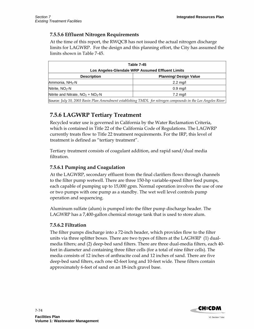
Section 7 Integrated Resources Plan Existing Treatment Facilities
7-74 Facilities Plan V1 Section 7.doc Volume 1: Wastewater Management
7.5.5.6 Effluent Nitrogen Requirements At the time of this report, the RWQCB has not issued the actual nitrogen discharge limits for LAGWRP. For the design and this planning effort, the City has assumed the limits shown in Table 7-45.
Table 7-45 Los Angeles-Glendale WRP Assumed Effluent Limits
Description Planning/ Design Value Ammonia, NH3-N 2.2 mg/l Nitrite, NO2-N 0.9 mg/l Nitrite and Nitrate, NO2 + NO3-N 7.2 mg/l Source: July 10, 2003 Basin Plan Amendment establishing TMDL for nitrogen compounds in the Los Angeles River
7.5.6 LAGWRP Tertiary Treatment Recycled water use is governed in California by the Water Reclamation Criteria, which is contained in Title 22 of the California Code of Regulations. The LAGWRP currently treats flow to Title 22 treatment requirements. For the IRP, this level of treatment is defined as “tertiary treatment”.
Tertiary treatment consists of coagulant addition, and rapid sand/dual media filtration.
7.5.6.1 Pumping and Coagulation At the LAGWRP, secondary effluent from the final clarifiers flows through channels to the filter pump wetwell. There are three 150-hp variable-speed filter feed pumps, each capable of pumping up to 15,000 gpm. Normal operation involves the use of one or two pumps with one pump as a standby. The wet well level controls pump operation and sequencing.
Aluminum sulfate (alum) is pumped into the filter pump discharge header. The LAGWRP has a 7,400-gallon chemical storage tank that is used to store alum.
7.5.6.2 Filtration The filter pumps discharge into a 72-inch header, which provides flow to the filter units via three splitter boxes. There are two types of filters at the LAGWRP (1) dual-media filters; and (2) deep-bed sand filters. There are three dual-media filters, each 40-feet in diameter and containing three filter cells (for a total of nine filter cells). The media consists of 12 inches of anthracite coal and 12 inches of sand. There are five deep-bed sand filters, each one 42-feet long and 10-feet wide. These filters contain approximately 6-feet of sand on an 18-inch gravel base.

Integrated Resources Plan Section 7 Existing Treatment Facilities
7-75
V1 Section 7.doc Facilities Plan Volume 1: Wastewater Management
Backwashing of both the dual-media filters and the deep-bed sand filters is typically performed once per day. The backwashing can be initiated automatically based on headloss through the filters or can be initiated manually. The current operational strategy calls for each filter backwash to be initiated manually by the operators once per shift. At the time backwashing occurs, influent flow to the filters is diverted to the other operating filters and a combination of filtered effluent and air from dedicated filter backwash blowers is used to fluidize the filter bed. The spent backwash water is returned by gravity to the NOS via the plant waste drain for ultimate treatment at the HTP. Table 7-46 summarizes the LAGWRP’s existing tertiary treatment facilities.
Table 7-46 Los Angeles-Glendale WRP – Existing Tertiary Treatment Facilities
Unit Value Coagulation Chemical Aluminum Sulfate Volume of Storage Tank 7,500 gallons Dual Media Filters Number 3 Type Sand/Anthracite Coal Diameter 40 ft Water Depth 3 ft Media depth – Sand 12 in Media depth – Anthracite Coal 12 in Filtration Rate 3.7 gpm/ ft2 Deep Bed Rectangular Filters Number 5 Media Sand Media Depth 6 ft Support Layer Gravel Support Layer Depth 1.5 ft Area 42 ft x 10 ft Filtration Rate 3.3 gpm/ ft2 Total Units 7 duty, 1 offline Source: From Integrated Plan for Wastewater Program documents and discussions with City staff
7.5.7 LAGWRP Disinfection To meet the reuse requirements dictated by Title 22, specific disinfection requirements must be met. Sodium hypochlorite (NaOCl) is used for disinfection at the LAGWRP. Two 6,500-gallon FRP chemical storage tanks located inside the Sodium Hypochlorite Building are used to store the sodium hypochlorite. Four 120-gph chemical metering pumps are available to deliver the sodium hypochlorite to the various application points.

Section 7 Integrated Resources Plan Existing Treatment Facilities
7-76 Facilities Plan V1 Section 7.doc Volume 1: Wastewater Management
The normal application point for disinfection is the filter effluent channel before the flow splits and feeds both chlorine contact tanks. Chemical feed to this point typically requires one metering pump. A combination of an ORP meter and chlorine residual analyzers are utilized to automatically control the dosing process. The LAGWRP has two chlorine contact tanks that provide up to three hours of detention at 20 mgd.
The LAGWRP doses chlorine solution to other application points on an occasional basis. These include the filter pump wetwell influent channel; the filters for shock chlorination, the RAS pump discharge header for filament control, and the primary clarifier inlet channel for odor control. Table 7-47 summarizes the LAGWRP’s existing disinfection facilities.
Table 7-47 Los Angeles-Glendale WRP – Existing Disinfection Facilities
Unit Value Chlorine Contact Basins Number 2 Tank 1 Area 177 ft x 65 ft Tank 1 Ave Water Depth 14 ft Tank 2 Area 215 ft x 66 ft Tank 2 Avenue Water Depth 14 ft Detention Period at 20 mgd 3 hours Chemical Storage Tank Chemical Sodium hypochlorite Concentration 12.5% Number 2 Capacities 6,500 gal Chemical Metering Pumps Number 4 Capacities 140 gph Source: From Integrated Plan for Wastewater Program documents and discussions with City staff
7.5.8 LAGWRP Dechlorination Effluent from the chlorine contact tanks flows by gravity via a 72-inch discharge pipe to the supplemental chlorine detention pond. The volume of the pond is approximately 5.5 MG.
From the pond it flows to an overflow weir structure where it is dechlorinated with sodium bisulfite. The overflow weir structure has two weirs: the pond overflow weir at the upstream end of the structure and a final weir at the down stream end. Sodium bisulfite is primarily added at the upstream pond overflow weir. Additional sodium bisulfite can be added at the final weir leaving the overflow weir structure to ensure that no chlorine residual remains in the plant effluent prior to discharge to the LA River.

Integrated Resources Plan Section 7 Existing Treatment Facilities
7-77
V1 Section 7.doc Facilities Plan Volume 1: Wastewater Management
Sodium bisulfite is stored in two 7,000-gallon chemical storage tanks located next to the overflow weir structure. Four 120-gph chemical metering pumps are available to deliver the sodium bisulfite to the two application points. Normal operation requires two pumps to be in operation while the other two are available as standby units. In the event of a power failure, there are two gravity discharge lines from the tanks to the two application points that allow the flow to the LA River to be dechlorinated. Table 7-48 summarizes the LAGWRP’s existing dechlorination facilities.
Table 7-48 Los Angeles-Glendale WRP – Existing Sodium Bisulfite Dechlorination Facilities
Unit Value Chemical Storage Tanks Chemical Sodium bisulfite Number 2 Capacity 7,000 gal Chemical Metering Pumps Chemical Sodium bisulfite Number 4 Capacities 68 gph Source: From Integrated Plan for Wastewater Program documents and discussions with City staff
7.5.9 LAGWRP Solids Handling The solids generating processes are primarily grit collection, primary sedimentation, secondary sedimentation, and filtration. The LAGWRP does not have a solids handling facility, nor is solids processing currently planned. All the solids generated from the various unit processes are discharged to the NOS and conveyed to the HTP for final treatment and reuse.
7.5.10 LAGWRP Effluent Reuse and Discharge Facilities 7.5.10.1 Effluent Reuse Effluent destined for reuse exits the chlorine contact tanks and flows to the recycled water pump wetwell located adjacent to the filter pump wet well. From there it can be pumped into a 30 inch force main, which terminates at a 2 mg circular storage tank located across the LA River and the Golden State Freeway in Griffith Park. The force main, which has a total length of approximately one mile, crosses under both the LA River and the Golden State Freeway through concrete encasements. The storage reservoir is a steel tank, 110 feet in diameter and 30 feet high, with a maximum water elevation of about 28 feet.

Section 7 Integrated Resources Plan Existing Treatment Facilities
7-78 Facilities Plan V1 Section 7.doc Volume 1: Wastewater Management
There are five 600 hp vertical turbine pumps located at the recycled water pump wet well available to pump recycled water into the recycled water distribution system. Separate facilities, consisting of onsite plant pumps and small-diameter pipelines, have been installed to provide a supply of recycled water to the Glendale Power Plant for industrial use. The DWP and the City of Glendale’s Public Service Department distribute the recycled water. The DWP operates and maintains the recycled water pump station for both agencies. There are currently over forty users of the recycled water produced by the LAGWRP. This plant’s recycled water is used mainly for irrigation of the Griffith Park golf course, but it is also used in cooling towers at the Glendale Power Plant and for industrial and process purposes at the LAGWRP.
7.5.10.2 Effluent Discharge The dechlorinated effluent from the overflow weir structure flows into a 72-inch pipe with a capacity of 75 mgd that leads to the river outlet structure. The effluent then flows from the river outlet structure to the LA River via three 66-inch pipes and a discharge structure constructed on the eastern bank of the LA River channel. Discharge is at a point in the river approximately five miles upstream of the Los Angeles Narrows. The river channel bottom at the point of discharge is unlined.
7.5.11 LAGWRP Unit Processes Capacity Evaluation 7.5.11.1 Background The LAGWRP began operation at full capacity in 1986. The plant is designed to provide tertiary treatment for an ADWF of 20 mgd. In 1991, the City completed retrofitting the secondary treatment process with a fine bubble diffuser system, which significantly reduced operating costs. In 1994, the City replaced the sulfur dioxide dechlorination system with a sodium bisulfite system. In 1996, the original chlorine gas disinfection system was replaced by a sodium-hypochlorite system.
The design parameters for the influent TSS and BOD concentrations are 250 mg/L and 200 mg/L, respectively. At a design flowrate of 20 mgd, these loads correspond to 41,700 ppd of TSS and 33,360 ppd of BOD. (Wastewater Facilities Plan Update, Final Report, DMJM/BV, September 1990). The current average influent characteristics (July 2001 to June 2002) are listed in Table 7-49.
Table 7-49 Los Angeles-Glendale WRP Average Influent Flow and Characteristics From July 2001 to June
2002 Description Value
Average Flow 17.6 mgd
Peak Flow 21.3 mgd
Average BOD 450 mg/l
Average TSS 545 mg/l
Source: Monthly Performance Reports July 2001 to June 2002

Integrated Resources Plan Section 7 Existing Treatment Facilities
7-79
V1 Section 7.doc Facilities Plan Volume 1: Wastewater Management
7.5.11.2 Capacity Evaluation An evaluation of the existing facilities at the LAGWRP has been performed to determine available process and hydraulic capacity or limitations based on increased influent flows. The results of this evaluation will provide a basis for developing the necessary planning criteria to meet future conditions and regulatory requirements.
As mentioned previously, the assumed existing situation includes all the proposed upgrades to implement biological nitrogen removal. To assist with subject effort, the planning process model BioWin was used to simulate process conditions at LAGWRP. However, it is important to note that additional criteria and inputs used for the planning model are based on the design values (Nitrogen Removal Conversion Phase 1, Draft Report, June 2002), pilot testing results, and discussions with City plant and engineering staff. An evaluation of hydraulic considerations at LAGWRP was performed by compiling and reviewing information from existing reports and studies, and through discussions with City staff. In-depth hydraulic modeling was not conducted for this planning effort.
The results of these efforts indicate that the secondary clarifiers are the major unit process with capacity limitations for the liquid process train. Pilot testing results showed that the increased load on the secondary clarifiers from the NdN converted aeration tanks (due to the higher mixed liquor concentration) will decrease the available capacity by approximately 25 percent (from 20 mgd to 15 mgd).
The modeling efforts have determined that the aeration tanks themselves should be able to treat up to the original capacity of 20 mgd with the addition of more secondary clarifiers. Table 7-50 summarizes the modeling results. For the IRP, it was assumed the existing LAGWRP capacity is 15 mgd, based on the secondary clarifiers. The current process capacities are summarized in Table 7-51.
Table 7-50 Los Angeles-Glendale WRP Planning Model Results
Description Modeling Results Planning Criteria
Flow, mgd 15 19 21 23 27 Predicted Operational Parameters MLSS, mg/l 2,200 2,800 3,150 3,450 4,050 2,000 to 4,000MCRT, days 8.5 8.7 8.9 9 9.3 5 to 15 RAS Ratio 1.5:1 1.5:1 1.5:1 1.5:1 1.5:1 1.5:1 WAS Flow, mgd 0.5 0.5 0.5 0.5 0.5 None Internal Recycle Ratio 2:1 2:1 2:1 2:1 2:1 4:1 MaximumNumber of Secondary Clarifiers Online
9 11 12 13 15 9 duty, 1
offline

Section 7 Integrated Resources Plan Existing Treatment Facilities
7-80 Facilities Plan V1 Section 7.doc Volume 1: Wastewater Management
Table 7-50 Los Angeles-Glendale WRP Planning Model Results
Secondary Clarifier SOR, gpd/ ft2 470 490 500 500 520 600
Secondary Clarifier SLR, lb/(day*ft2)
22 29 33 36 44 181
Model Predicted Effluent Quality BOD, mg/l 4.1 4.8 5.2 5.6 6.4 20 TSS, mg/l 5.6 7 7.8 8.6 10.2 15 NH3-N, mg/l 1.95 1.98 1.95 1.97 1.95 2 NO3-N + NO2-N, mg/l 2.7 2.7 2.7 2.7 2.7 8 Total Inorganic Nitrogen (TIN), mg/l
4.7 4.7 4.7 4.7 4.7 10
Source: From operations staff
Table 7-51 Los Angeles-Glendale WRP Unit Process Capacities
Existing Capacity
Unit Processes Average Dry Weather
Flow (ADWF) Treatment Capacity
Hydraulic Capacity
Preliminary Treatment1 (i.e. Headworks and Grit Removal) 60 mgd
Primary Treatment Clarifiers
20 mgd
Secondary Treatment with Nitrogen Removal Aeration Tanks Clarifiers
20 mgd 15 mgd
Tertiary Treatment Filters
29.5 mgd
Disinfection Chlorine Contact Basins @ 120 min.
32 mgd
Effluent Outfall 70 mgd Note: 1. Hydraulic capacity with all units on-line and is limited by the bar screens
7.6 Terminal Island Treatment Plant The TITP serves the harbor area and has been operating since the 1935. Built originally as a primary facility, the plant was upgraded and expanded to secondary treatment (1973), to tertiary treatment (filtration) (1996), and to 6 mgd of advanced treatment (microfiltration and reverse osmosis) (2001). Currently, TITP has the capacity to provide tertiary treatment (secondary treatment and filtration) for an ADWF of 30 mgd.

Integrated Resources Plan Section 7 Existing Treatment Facilities
7-81
V1 Section 7.doc Facilities Plan Volume 1: Wastewater Management
Like the HTP, the TITP is an end-of-the-line plant, subjected to normal diurnal and seasonal flow variation. The TITP provides preliminary, primary, secondary and tertiary treatment. The TITP currently discharges tertiary effluent to the Los Angeles Harbor. The completion of the advanced treatment facilities will allow the plant to recycle wastewater and eventually eliminate effluent discharge to the Los Angeles Harbor. Solids are thickened, anaerobically digested, dewatered, and hauled to Kern, San Diego, Los Angeles, and Riverside Counties for land application and reuse as a soil amendment.
7.6.1 TITP Location and Service Area The TITP is located on Terminal Island, which is approximately 20 miles south of downtown Los Angeles. It is situated on a 19.8-acre site at the northwest corner of Terminal Way and Ferry Street. The location of this plant is shown in Figure 3-1 of Section 3.
The plant’s service area includes the communities of Wilmington, San Pedro, Terminal Island, and a part of Harbor City. Aside from residential waste, the plant receives waste from the fish processing industries, petroleum industries, and docking and storage facilities. The total flow into the plant contains about 60 percent industrial waste. Raw wastewater reaches the TITP through via a series of pumping plants and force mains. The tributary area to the TITP is shown in Figure 4-1 of Section 4.
7.6.2 TITP Existing Capacity The TITP is designed to treat an ADWF of 30 mgd and a PWWF of 55 mgd of wastewater.
The design parameters for the influent total suspended solids (TSS) and 5-day biochemical oxygen demand (BOD5) concentrations are 337 mg/L and 312 mg/L, respectively. At a design influent flowrate of 30 mgd, these loads correspond to 84,000 ppd of TSS and 78,000 ppd of BOD5. Advanced Planning Report, Technical Memorandum-3I-Summary of the Existing Facilities of the Terminal Island Treatment Plant (City, 1988) (APR TM-3I).
The TITP provides preliminary, primary, secondary, tertiary, advanced and solids handling and treatment facilities. The basic unit processes include:
Preliminary Treatment: Flow metering, screening, grit removal.
Primary Treatment: Flow metering, primary sedimentation, and raw sludge and scum removal and conveyance.
Secondary Treatment: Air activated sludge, final sedimentation, and RAS, and WAS piping and WAS thickening.
Tertiary Treatment: Deep-bed, multi-media filters.

Section 7 Integrated Resources Plan Existing Treatment Facilities
7-82 Facilities Plan V1 Section 7.doc Volume 1: Wastewater Management
Advanced Treatment: Microfiltration and Reverse Osmosis (MF/RO).
Effluent Discharge System: Effluent outfall to Los Angeles Harbor.
Solids handling and Treatment: WAS thickening, anaerobic digesters, sludge screening, sludge dewatering, dewatered sludge storage and truck loading facility, and digester gas handling.
Figure 7-15 presents the TITPs site plan and Figure 7-16 shows the process flow diagram.
7.6.2.1 TITP Preliminary Treatment The preliminary treatment process removes large size particles and grit from the incoming flow to protect the equipment downstream.
Screening The TITP Headworks Building includes two 30-mgd mechanically cleaned bar screens (one duty, one standby) to remove large particles and materials. The bar screens remove large particles while allowing the liquid stream to flow through. Removed screenings are hauled to a landfill for disposal.

Figure 7-15
Terminal Island Treatment Plant Existing Site Plan

Facilities PlanWastewater Management Volume
Section 7Existing Treatment FacilitiesIntegrated Resources Plan - Interim Deliverable
Figure 7-16Terminal Island Treatment Plant
Process Flow Diagram

Integrated Resources Plan Section 7 Existing Treatment Facilities
7-85
V1 Section 7.doc Facilities Plan Volume 1: Wastewater Management
Grit Removal Grit removal is accomplished by three aerated grit basins, which are 10-feet by 61-feet with a 10-foot sidewater depth. The grit basins are located adjacent to the Headworks building. The aerated grit basins are equipped with chain and bucket systems. Settled grit is collected and disposed into a hopper where it is hauled to a sanitary landfill. The liquid flow out of the grit removal system is conveyed into the primary treatment process. Table 7-52 summarizes the TITP’s existing preliminary treatment facilities.
Table 7-52 Terminal Island Treatment Plant
Existing Preliminary Treatment Facilities Unit Value
Screenings Removal Type Mechanically Raked Number 2 Capacity, each 30 mgd Grit Chamber Type Aerated Number 3 Area 10ft x 61ft x 10 ft Overflow Rate (2 chambers) 45,100 gpd/ ft2 Detention Time (3 chambers) 3.14 min
7.6.2.2 TITP Primary Treatment The primary treatment process removes the majority of settleable organic and inorganic materials that enters the plant. Floatable material is removed by surface skimming. These functions significantly reduce the BOD5 and TSS loadings on the secondary treatment processes.
The TWRP’s existing primary treatment facilities consist of 6 rectangular primary clarifiers, which are 250-feet x 20-feet, with a 11.9-foot average water depth. The detention time in these basins is 2.14 hours at design average flow, with a surface overflow rate of 1,000 gpd/ ft2. These tanks use plastic chain and sprockets with fiberglass flights to transport settled solids to the inlet end of each tank, while floating materials are skimmed to the opposite end. The raw sludge, grease, and floatables are removed from each tank and pumped to the digesters for treatment. At the end of the tanks, a concrete channel collects all the primary treated wastewater and conveys it into the secondary treatment process. Table 7-53 summarizes the TWRP’s existing primary treatment facilities.

Section 7 Integrated Resources Plan Existing Treatment Facilities
7-86 Facilities Plan V1 Section 7.doc Volume 1: Wastewater Management
Table 7-53
Terminal Island Treatment Plant Existing Primary Treatment Facilities
Unit Value Primary Clarifiers Number of Tanks 6 Area 20ft x 250ft Average Water Depth 11.9 ft Overflow Rate 1,000 gpd/ ft2 Detention Time 2.14 hours Capacity 30 mgd
7.6.2.3 TITP Secondary Treatment The TITP was designed with conventional standard-rate activated sludge process for the removal and/or stabilization of BOD5 and related organic suspended solids.
Aeration Tanks The secondary treatment process removes organic matter contained in wastewater. The process involves the use of microorganisms, or activated sludge, which consumes the organic matter in wastewater. Aeration tanks are used to provide oxygen for the activated sludge. It also facilitates the mixing of the wastewater and activated sludge. At the end of each tank, the mixture of activated sludge and wastewater is collected and conveyed into clarifiers.
The TITP has nine rectangular aeration tanks, 30-feet x 300-feet, with a 15-foot sidewater depth. The TITP aeration tanks have fine-bubble diffusers. Since the TITP receives a significant proportion of its influent from industrial facilities, staff operates the aeration tanks to provide full nitrification/partial denitrification to reduce nitrogenous BOD5 and thereby meet the total BOD5 discharge limits. Operating in this mode reduces the available treatment volume of the aeration facilities, and limits the secondary treatment capacity to approximately 22 mgd. However, since all of the plant flow will be treated by reverse osmosis by 2020, for the IPWP it was assumed that advanced treatment will provide adequate nitrogen removal to meet discharge requirements. Therefore, a secondary treatment capacity of 30 mgd will be assumed.
Process Air System Process air is supplied by up to three 1,500-hp centrifugal blowers, each capable of delivering up to 36,600 scfm of air. Currently, the plant operates with one duty and two standby blowers. Air is delivered through headers and downcomer pipes to each grid of fine-bubble diffusers.

Integrated Resources Plan Section 7 Existing Treatment Facilities
7-87
V1 Section 7.doc Facilities Plan Volume 1: Wastewater Management
Final Clarifiers The TITP has a total of 18 final clarifiers, which are 150-feet by 20-feet, with a 12-foot sidewater depth. The clarifiers are divided into two batteries of 9 tanks each, arranged so that their effluent ends discharge into a common channel between the two batteries.
The TITPs final clarifiers are arranged with their sludge hoppers at the effluent end, beneath the effluent weirs. There are two hoppers per tank with sludge withdrawal piping manifolded to a common meter and control valve for each tank. Two variable speed vertical centrifugal pumps withdraw RAS from the wet well and pump it back to the influent end of the aeration basins. Table 7- 54 summarizes the TITP’s existing secondary treatment facilities:
Table 7-54 Terminal Island Treatment Plant
Existing Secondary Treatment Facilities Unit Value
Aeration Tanks Type Conventional, 3 pass Number 9 Area 30ft x 300ft Average Water Depth 15ft Sludge Retention Time 5.5 hours Design Capacity 30 mgd Process Air Blowers Type Centrifugal Number 3 Capacity, each 36,600 scfm Secondary Clarifiers Number 18 Area 20ft x 150ft Average Water Depth 12 ft Overflow Rate 555 gpd/ ft2 Detention Time 2.9 hours Design Capacity 30 mgd
7.6.2.4 TITP Tertiary Treatment The TITP uses deep bed multi-media filters to filter out the small particles in the wastewater. A backwash system is used to remove the trapped particles in the filters and the particles are discharged into the primary clarifiers. The results are a reduction of settleable solids, suspended solids, and turbidity in the wastewater effluent. The clarified liquid stream that is produced is discharged into the Los Angeles Harbor. When the Phase I advanced treatment facility becomes operational, a portion of the flow out of the filters will be diverted into the facility for further treatment.
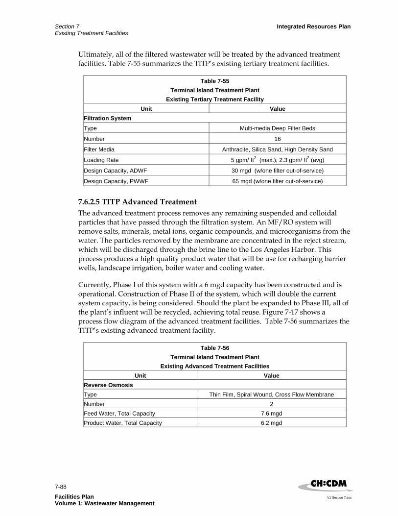
Section 7 Integrated Resources Plan Existing Treatment Facilities
7-88 Facilities Plan V1 Section 7.doc Volume 1: Wastewater Management
Ultimately, all of the filtered wastewater will be treated by the advanced treatment facilities. Table 7-55 summarizes the TITP’s existing tertiary treatment facilities.
Table 7-55 Terminal Island Treatment Plant
Existing Tertiary Treatment Facility Unit Value
Filtration System
Type Multi-media Deep Filter Beds
Number 16
Filter Media Anthracite, Silica Sand, High Density Sand
Loading Rate 5 gpm/ ft2 (max.), 2.3 gpm/ ft2 (avg)
Design Capacity, ADWF 30 mgd (w/one filter out-of-service)
Design Capacity, PWWF 65 mgd (w/one filter out-of-service)
7.6.2.5 TITP Advanced Treatment The advanced treatment process removes any remaining suspended and colloidal particles that have passed through the filtration system. An MF/RO system will remove salts, minerals, metal ions, organic compounds, and microorganisms from the water. The particles removed by the membrane are concentrated in the reject stream, which will be discharged through the brine line to the Los Angeles Harbor. This process produces a high quality product water that will be use for recharging barrier wells, landscape irrigation, boiler water and cooling water.
Currently, Phase I of this system with a 6 mgd capacity has been constructed and is operational. Construction of Phase II of the system, which will double the current system capacity, is being considered. Should the plant be expanded to Phase III, all of the plant’s influent will be recycled, achieving total reuse. Figure 7-17 shows a process flow diagram of the advanced treatment facilities. Table 7-56 summarizes the TITP’s existing advanced treatment facility.
Table 7-56 Terminal Island Treatment Plant
Existing Advanced Treatment Facilities Unit Value
Reverse Osmosis Type Thin Film, Spiral Wound, Cross Flow Membrane Number 2 Feed Water, Total Capacity 7.6 mgd Product Water, Total Capacity 6.2 mgd

Facilities PlanWastewater Management Volume
Section 7Existing Treatment FacilitiesIntegrated Resources Plan - Interim Deliverable
Figure 7-17Terminal Island Treatment Plant
Advanced Treatment Process Flow Diagram

Section 7 Integrated Resources Plan Existing Treatment Facilities
7-90 Facilities Plan V1 Section 7.doc Volume 1: Wastewater Management
7.6.2.6 TITP Solids Handling and Treatment The solids handling facilities provide the treatment for the sludge collected at the primary clarifiers and the secondary clarifiers prior to ultimate discharge and reuse. This process involves the following sequential stages: thickening, stabilization, dewatering, and reuse. The facilities consist of a dissolved air flotation thickener, sludge blending tank, egg-shaped anaerobic digesters, and centrifuges.
The capacity of the solids handling facilities is based on the Design Criteria presented in the Concept Report Terminal Island Treatment Plan Solids Handling Facility Upgrade, City of Los Angeles, 1992. The quantity of dewatered sludge dry solids is based on the following criteria:
Digested sludge flow of 180 gpm
Total solids in digested sludge of 2.3 percent
Digested sludge dry solids of 50,467 lbs/d
Total solids in dewatered sludge of 22 percent
The resultant quantity of dewatered sludge dry solids is 35,700 lbs/d or approximately 19 dry tons per day (dtpd). Table 7-57 summarizes the solids handling facilities.
Table 7-57 Terminal Island Treatment Plant
Existing Solids Handling and Treatment Facilities Unit Value
Anaerobic Digesters Type Egg Shaped Anaerobic Digesters Number 4 Hydraulic Capacity 1.38 MG Hydraulic Detention Time 15 days WAS Thickener Circular Dissolved Air Floatation Tank Number of Tanks 1 Capacity 83,000 gallons Loading Rate 1.27 lbs/hr/ ft2 Sludge Dewatering Type Centrifuges Number 4 Capacity 2@90 gpm, 1@250 gpm % Solids in Wetcake 2@22%, 1@25%

Integrated Resources Plan Section 7 Existing Treatment Facilities
7-91
V1 Section 7.doc Facilities Plan Volume 1: Wastewater Management
Pilot testing has been completed for full-scale digestion system at the TITP to produce Class A quality biosolids under thermophilic conditions. The system is now operating under thermophilic conditions and producing Class A biosolids (see Section 9 for more information). The Terminal Island Renewable Energy (TIRE) project, which will extract methane gas from biosolids injected into the ground, is also currently in the design phase.
7.6.2.7 TITP Effluent Discharge System The effluent discharge system discharges the plant’s treated wastewater into the Los Angeles Harbor. The system consists of a centrifugal pump system and a 48-inch pipeline that connects to a 60-inch outfall that terminates 1,000 feet into the Los Angeles Harbor. At low flow and/or low tides, the plant’s discharge into the harbor is by gravity flow.
In October 1994, an agreement between the RWQCB and the City of Los Angeles was reached to phase out discharge of wastewater into the harbor. By the year 2020, all of the plant’s effluent will be recycled. Table 7-58 summarizes the effluent discharge facilities.
Table 7-58 Terminal Island Treatment Plant
Existing Effluent Discharge Facility Unit Value
Effluent Pumps Type Centrifugal, variable speed Number 2 Capacity 52,000 gpm, each Ocean Outfall Pipe Size 60 in. Length 5,875 ft Capacity 66 mgd1
Note: Based on design peak wet weather flow for plant.
7.6.2.8 TITP Buildout Capacity The current site does not have any space available for additional building. The limited space available was used in the construction of the filtration system and RO system. Any additional facilities would have to be built off-site.
7.6.2.9 TITP Summary of Existing and Buildout Capacities A summary of the existing and buildout treatment plant capacities for the levels of treatment considered under the IPWP are presented in Table 7-59. These capacities will serve as the basis for the IPWP shortfall and alternatives analyses.

Section 7 Integrated Resources Plan Existing Treatment Facilities
7-92 Facilities Plan V1 Section 7.doc Volume 1: Wastewater Management
Table 7-59 Terminal Island Treatment Plant
Existing and Buildout Capacity Summary Existing Capacity Buildout Capacity
Unit Process ADWF PWWF ADWF PWWF Tertiary Treatment1 30 mgd 50 mgd 30 mgd 50 mgd
Advanced Treatment2 0 mgd 0 mgd 30 mgd 30 mgd
Effluent Outfall3 66 mgd 66 mgd 66 mgd 66 mgd
Solids Handling Facilities4 19 dtpd 19 dtpd 19 dtpd 19 dtpd
Notes: 1Includes preliminary, primary, secondary, and tertiary facilities. 2Includes preliminary, primary, secondary, tertiary facilities and advanced treatment facilities. 3Outfall capacity is based on a maximum design flow of 66 mgd (Weston 2000) 4Source: APR TM-10W (City 1990)