SECTION 600: STREET LIGHTING & TRAFFIC SIGNALS 601 …
60
600-1 REV 04/20/20 SECTION 600: STREET LIGHTING & TRAFFIC SIGNALS Page No. Description 600-2 601 GENERAL 600-2 601.1 SPECIFICATIONS 600-2 601.2 RESOLUTION OF CONFLICTS 600-2 601.3 START OF CONSTRUCTION 600-2 601.4 RECORD DRAWINGS 600-3 602 MATERIALS 600-3 602.1 GENERAL 600-3 602.2 STREET LIGHTING POLES 600-6 602.3 BREAK-AWAY DEVICE 600-6 602.4 STREET LIGHTING POLE FOUNDATIONS 600-8 602.5 LUMINAIRES 600-9 602.6 PHOTO-CELL 600-11 602.7 UNDERGROUND CONDUITS AND ELECTRICAL CABLE 600-12 602.8 ELECTRICAL CABLE, 600 VOLT 600-13 602.9 LIGHTING CABLE FUSE KITS 600-13 602.10 CAST-IN PLACE CONCRETE HANDHOLES 600-14 602.11 COMPOSITE CONCRETE HANDHOLES 600-14 602.12 GROUNDING 600-14 602.13 GROUND ROD 600-15 602.14 STREET LIGHTING CONTROLLER 600-21 602.15 LABELS 600-23 603 CONSTRUCTION REQUIREMENTS 600-23 603.1 TRAFFIC SIGNAL SYSTEMS CONTRACTOR PRE-QUALIFICATIONS 600-23 603.2 TRAFFIC SIGNAL SYSTEMS 600-23 603.3 TRENCH AND BACKFILL FOR ELECTRICAL WORK 600-23 603.4 YELLOW WARNING TAPE OVER STREET LIGHTING CABLE 600-23 603.5 TRAFFIC SIGNAL SYSTEM SERVICE INSTALLATION 600-24 603.6 CONDUIT 600-24 603.7 WIRE AND CABLE 600-24 603.8 LUMINAIRES 600-24 603.9 LIGHT POLES AND BREAKAWAY DEVICES 600-24 603.10 FOUNDATIONS 600-24 603.11 HANDHOLES 600-25 604 INSPECTIONS AND TESTING 600-25 604.1 STREET LIGHTING SYSTEMS 600-25 604.2 TRAFFIC SIGNAL SYSTEMS 600-26 690 STANDARD DETAILS
Transcript of SECTION 600: STREET LIGHTING & TRAFFIC SIGNALS 601 …

600-1
REV 04/20/20
SECTION 600:
STREET LIGHTING & TRAFFIC SIGNALS
Page No. Description
600-2 601 GENERAL
600-2 601.1 SPECIFICATIONS
600-2 601.2 RESOLUTION OF CONFLICTS
600-2 601.3 START OF CONSTRUCTION
600-2 601.4 RECORD DRAWINGS
600-3 602 MATERIALS
600-3 602.1 GENERAL
600-3 602.2 STREET LIGHTING POLES
600-6 602.3 BREAK-AWAY DEVICE
600-6 602.4 STREET LIGHTING POLE FOUNDATIONS
600-8 602.5 LUMINAIRES
600-9 602.6 PHOTO-CELL
600-11 602.7 UNDERGROUND CONDUITS AND ELECTRICAL CABLE
600-12 602.8 ELECTRICAL CABLE, 600 VOLT
600-13 602.9 LIGHTING CABLE FUSE KITS
600-13 602.10 CAST-IN PLACE CONCRETE HANDHOLES
600-14 602.11 COMPOSITE CONCRETE HANDHOLES
600-14 602.12 GROUNDING
600-14 602.13 GROUND ROD
600-15 602.14 STREET LIGHTING CONTROLLER
600-21 602.15 LABELS
600-23 603 CONSTRUCTION REQUIREMENTS
600-23 603.1 TRAFFIC SIGNAL SYSTEMS CONTRACTOR PRE-QUALIFICATIONS
600-23 603.2 TRAFFIC SIGNAL SYSTEMS
600-23 603.3 TRENCH AND BACKFILL FOR ELECTRICAL WORK
600-23 603.4 YELLOW WARNING TAPE OVER STREET LIGHTING CABLE
600-23 603.5 TRAFFIC SIGNAL SYSTEM SERVICE INSTALLATION
600-24 603.6 CONDUIT
600-24 603.7 WIRE AND CABLE
600-24 603.8 LUMINAIRES
600-24 603.9 LIGHT POLES AND BREAKAWAY DEVICES
600-24 603.10 FOUNDATIONS
600-24 603.11 HANDHOLES
600-25 604 INSPECTIONS AND TESTING
600-25 604.1 STREET LIGHTING SYSTEMS
600-25 604.2 TRAFFIC SIGNAL SYSTEMS
600-26 690 STANDARD DETAILS

Section 6: Street Lighting & Traffic Signals Naperville Standard Specification
600-2
REV 04/20/20
601 GENERAL
The standards and requirements found in this article are for the materials and construction of street
lighting and traffic signal systems within the City of Naperville, Illinois.
601.1 SPECIFICATIONS
All work and equipment performed and installed under this section shall be governed by and shall
comply with the following specifications, manuals, and codes listed in Section 102.2. The most
current editions and all subsequent revisions and alterations for the specifications are required.
601.2 RESOLUTION OF CONFLICTS
In the event of conflict between the City Standard Specifications and the documents listed in Section
102.2, the City Standard Specifications shall take precedence and/or the City Engineer’s decision will
prevail. Any questions arising from these specifications should be directed in writing to the City
Engineer for a determination.
601.3 START OF CONSTRUCTION
The contractor shall not begin construction until all required permits have been obtained. Copies of
all permits obtained by outside agencies must be provided to the city prior to the start of construction.
601.4 RECORD DRAWINGS
Upon completion of work, the contractor shall provide Record Drawings information in conformance
with the requirements of Section 110.
Section 6: Street Lighting & Traffic Signals Naperville Standard Specification
600-3
REV 04/20/20
602 MATERIALS
602.1 GENERAL
The materials and equipment for installation of street lighting on public streets in Naperville are
detailed in the following sections. Other street lighting equipment, such as the East Central
Homeowners Organization (ECHO) decorative neighborhood street lights, and the Central Business
District (CBD) lights are restricted for use on public streets in their designated areas (ECHO and the
CBD), unless otherwise directed by the City Council. Specialized lighting equipment for CBD,
ECHO, and other designated areas within the City shall be identical to existing equipment unless
otherwise directed by the City Engineer.
602.2 STREET LIGHTING POLES
Light poles shall be in accordance with the Section 1069 of the IDOT Standard Specifications.
The contractor shall submit the technical information, to include catalog cut sheets, for each
electrical material item for approval prior to ordering the equipment. The pole shall be “UL
Listed” with a UL Classification label as complying with UL Standard 1572. All poles shall have
an identification label (Detail 690.10).
602.2.1 LOCAL AND NEIGHBORHOOD CONNECTOR STREETS
Street light poles for local and neighborhood connector streets shall be:
a) Street lighting poles shall be spun aluminum and have 23 foot mounting height with a
single 8 foot davit arm and cobra head type LED luminaire (Detail 690.01).
• The outside diameter of the top of the pole shall be 4.5 inches.
• The outside diameter of the base of the pole shall be 7 inches.
• The wall thickness shall be a minimum of 0.156 inches.
• The bolt circle of the pole base shall be a minimum of 10 inches and a maximum
of 11 inches in diameter.
• The luminaire arm shall be davit type of 4 1/2 inch diameter tapered to 2 3/8 inch
diameter of bending radius 4 feet. The davit arm shall be fastened to the pole by
1/2 inch stainless steel bolts, nuts, and lock washers.
• The pole and arm shall be finished in a Dark Bronze Powder Coat finish over 100
grit polished finished surface. The Dark Bronze Powder Coat finish shall have a
minimum 5-year guarantee by the manufacturer.
602.2.2 COLLECTOR STREETS
Street light poles for collector streets shall be:
a) Street lighting poles for residential areas shall be spun aluminum and have 32 foot
mounting height with either a single 10 foot davit arm and cobra head type LED luminaire,
or twin 10 foot davit arms and cobra head type LED luminaires (Details 690.02 and
690.03).
• The outside diameter of the top of the pole shall be 4.5 inches.
• The outside diameter of the base of the pole shall be 8 inches.

Section 6: Street Lighting & Traffic Signals Naperville Standard Specification
600-4
REV 04/20/20
• The wall thickness shall be a minimum of 0.219 inches.
• The bolt circle of the pole base shall be a minimum of 11 inches and a maximum
of 12 inches in diameter.
• The luminaire arm shall be davit type of 4 1/2 inch diameter tapered to 2 3/8 inch
diameter of bending radius 5 feet. The davit arm shall be fastened to the pole by
1/2 inch stainless steel bolts, nuts, and lock washers.
• The pole and arm shall be finished in a Dark Bronze Powder Coat finish over 100
grit polished finished surface. The Dark Bronze Powder Coat finish shall have a
minimum 5-year guarantee by the manufacturer
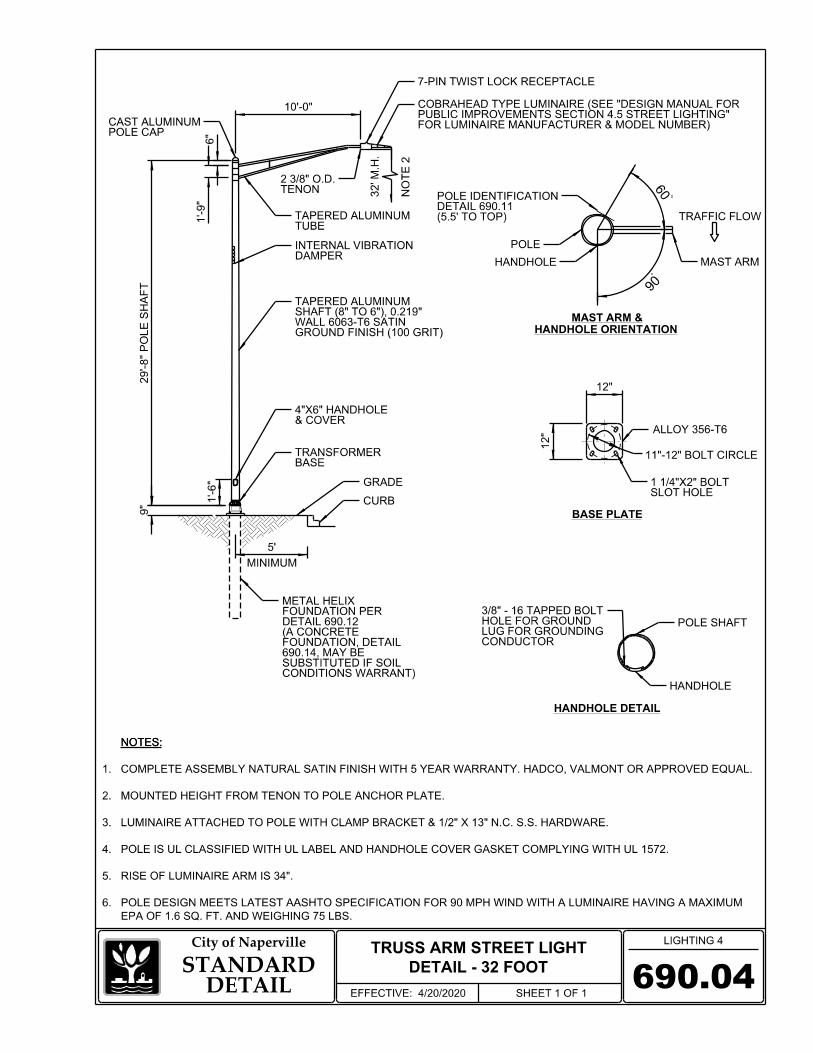
b) Street lighting poles for non-residential areas shall be spun aluminum and have 32 foot
mounting height with either a single 10 foot truss arm and cobra head type LED luminaire
or twin 10 foot truss arms and cobra head type LED luminaire (Details 690.04 and 690.05).
• The outside diameter of the top of the pole shall be 6 inches.
• The outside diameter of the base of the pole shall be 8 inches.
• The wall thickness shall be a minimum of 0.219 inches.
• The bolt circle of the pole base shall be a minimum of 11 inches and a maximum
of 12 inches in diameter.
• The luminaire arm shall be truss type with a rise of 34 inches. The arm shall be
secured to the pole shaft by a clamp type bracket. The arm shall be mounted to the
pole by a clamp style bracket by four 1/2 inch stainless steel bolts, nuts, and lock
washers.
• The pole and arm shall have natural aluminum finish with a 100 grit polished
finished surface.
602.2.3 ARTERIAL STREETS
Street light poles for arterial streets shall be:
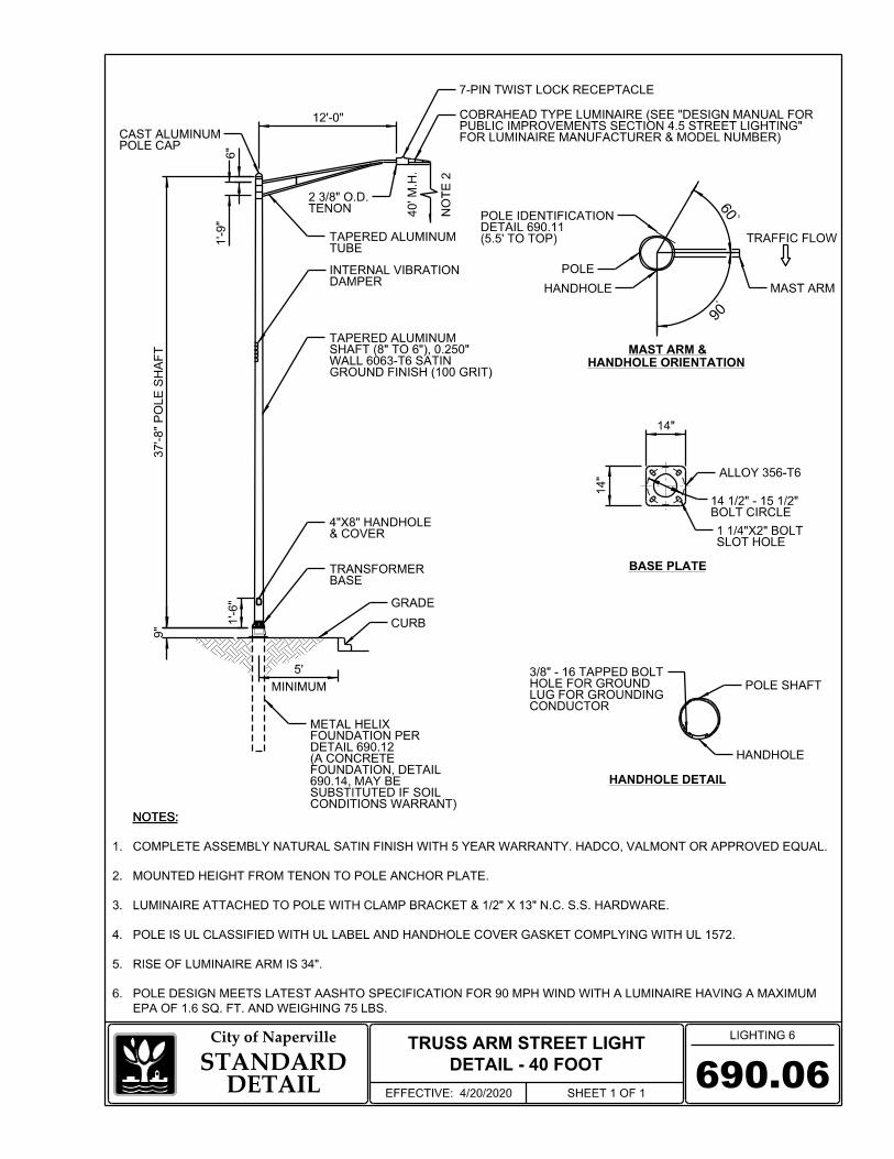
a) Street lighting poles for minor arterial streets shall be spun aluminum and have 40 foot
mounting height with a single 12 foot truss arm and cobra head type LED luminaire (Detail
690.06).
• The outside diameter of the top of the pole shall be 6 inches.
• The outside diameter of the base of the pole shall be than 8 inches.
• The wall thickness shall be a minimum of 0.250 inches.
• The bolt circle of the pole base shall be a minimum of 14 ½ inches and a maximum
of 15 ½ inches in diameter.
• The luminaire arm shall be truss type with a rise of 34 inches. The arm shall be
secured to the pole shaft by a clamp type bracket. The arm shall be mounted to the
pole by a clamp style bracket by four 1/2 inch stainless steel bolts, nuts, and lock
washers.
• The pole and arm shall have natural aluminum finish with a 100 grit polished
finished surface.

Section 6: Street Lighting & Traffic Signals Naperville Standard Specification
600-5
REV 04/20/20
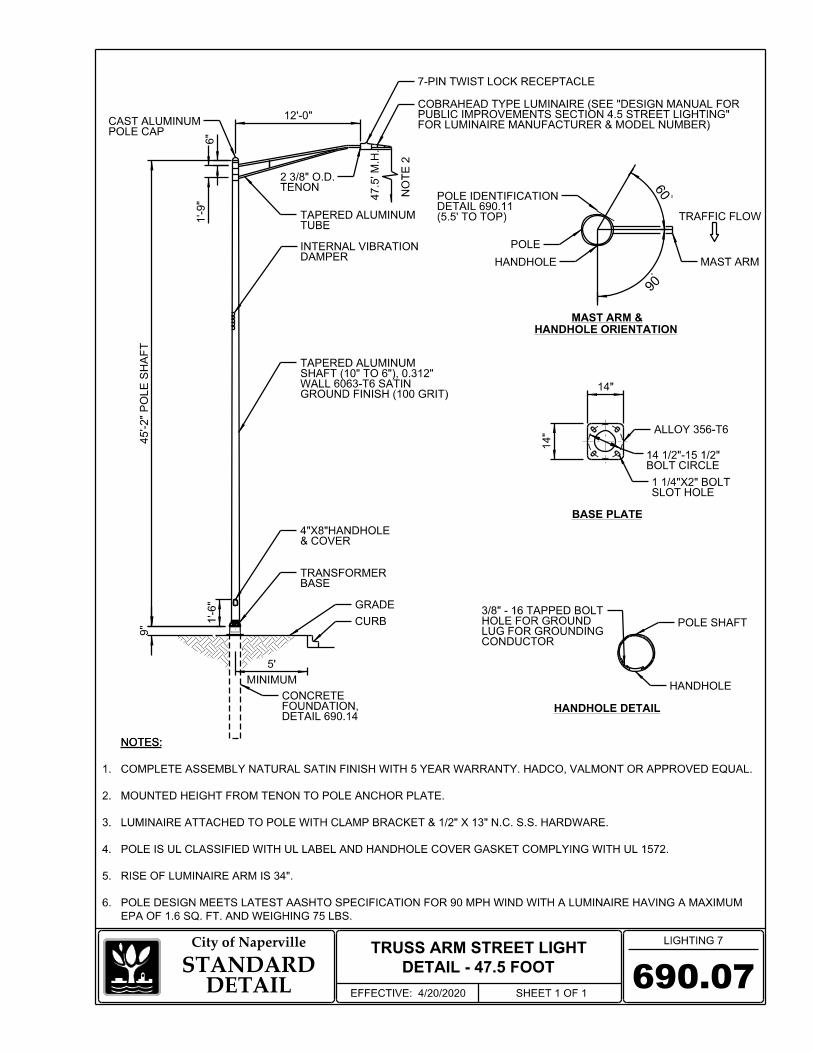
b) Street lighting poles for major arterial street shall be spun aluminum and have 47.5 foot
mounting height with either a single 12 foot truss arm and cobra head type LED luminaire,
or twin 12 foot truss arms and cobra head type LED luminaires (Details 690.07 and 690.08).
• The outside diameter of the top of the pole shall be 6 inches.
• The outside diameter of the base of the pole shall be 10 inches.
• The wall thickness shall be a minimum of 0.312 inches.
• The bolt circle of the pole base shall be a minimum of 14 1/2 inches and a maximum
of 15 1/2 inches in diameter.
• The luminaire arm shall be truss type with a rise of 34 inches. The arm shall be
secured to the pole shaft by a clamp type bracket. The arm shall be mounted to the
pole by a clamp style bracket by four 1/2 inch stainless steel bolts, nuts, and lock
washers.
• The pole and arm shall have natural aluminum finish with a 100 grit polished
finished surface.
602.2.4 CENTRAL BUSINESS DISTRICT (CBD)
Street light poles for CBD area streets shall be:
a) Pedestrian lighting poles shall be fluted aluminum have 10 foot mounting height with a
post top Caged Acorn type LED luminaire (Detail 690.09).
• The outside diameter of the pole shall be 4 inches.
• The wall thickness shall be a minimum of 0.188 inches.
• The bolt circle of the pole base shall be 8 3/4 inches in diameter (3 bolts at 120
degrees).
• 20 ampere-120 volt GFCI receptacle with in-use rated cover.
• The pole shall be finished in a Black Powder Coat finish over 100 grit polished
finished surface. The Black Powder Coat finish shall have a minimum 5-year
guarantee by the manufacturer.
b) Street lighting poles shall be spun aluminum and have 30 foot mounting height with a
single side mounted area type LED luminaire (Detail 690.10).
• The outside diameter of the top of the pole shall be 6 inches.
• The outside diameter of the pole at the base shall be 10 inches.
• The wall thickness shall be a minimum of 0.250 inches.
• The bolt circle of the pole base shall be a minimum of 14 inches and a maximum
of 15 inches in diameter.
• 20 ampere-120 volt GFCI receptacle with in-use rated cover.
• The pole shall be finished in a Black Powder Coat finish over 100 grit polished
finished surface. The Black Powder Coat finish shall have a minimum 5-year
guarantee by the manufacturer.
Section 6: Street Lighting & Traffic Signals Naperville Standard Specification
600-6
REV 04/20/20
602.3 BREAK-AWAY DEVICE
All poles except “Caged Acorn Street Light – 10 Foot (CBD)” shall be connected to the foundation
by a breakaway device of a frangible box design (Detail 690.16). Frangible coupling bolts are not
acceptable. The breakaway device shall be in accordance with Article 1070.04(b) of the IDOT
Standard Specifications. The device shall be approximately 9 inches tall and shall have an aluminum
access door. Certification shall be submitted from the supplier of a breakaway device that the
particular design meets current AASHTO breakaway requirements. The contractor shall submit the
technical information, to include catalog cut sheets. Breakaway devices installed on powder coated
poles shall be powder coated to match the color of the pole.
602.4 STREET LIGHTING POLE FOUNDATIONS
602.4.1 METAL FOUNDATION – RESIDENTIAL AND NEIGHBORHOOD CONNECTOR
a) Metal foundations for street lighting poles for residential and neighborhood connector
streets shall be 5 feet in length. The contractor shall submit the technical information, to
include catalog cut sheets, for the metal foundation for approval prior to ordering the
equipment (Detail 690.12).
b) The metal foundation, 5 foot, shall comply with the requirements of Article 1070.01 of the
IDOT Standard Specifications and be manufactured and certified by Hubbell-Chance
Company or approved equal by the City Engineer.
c) The base plate shall be 12 inch by 12 inch by 1 inch thick. The bolt circle shall be 10 1/2
inch in diameter. The base plate shall have holes drilled and tapped to accept 1 inch
diameter threaded studs and jam nuts. The base plate shall be clearly and permanently
marked to easily identify the location of the two cable way openings in the shaft. The
baseplate shall be AASHTO M 270M, Grade 36
d) The shaft shall be 8 5/8 inches in diameter, machine flame cut to a 5 foot length, with two
18 inch by 2 1/2 inch cable ways located 15 inches below the base plate separated by 180
degrees. The shaft shall be capable of withstanding 10,000-foot pounds of torque after
being joined to the base plate.
e) The helix shall be produced by welding 3/8 inch thick steel in a 16 inch diameter helix with
a 3 inch pitch to allow for the passage of thicker gravel.
f) The pilot point shall be sheared on a 45 degree angle from 1 1/4 inch round steel bar made
of AASHTO M 270 (ASTM 575) steel and at least 6 inches in length.
g) The studs shall be 1 inch diameter in accordance with AASHTO M 314. Nuts shall be
hexagon nuts according to AASHTO M 291M and washers shall be according to AASHTO
M 293.
h) All material shall be galvanized according to AASHTO M 111.

Section 6: Street Lighting & Traffic Signals Naperville Standard Specification
600-7
REV 04/20/20
602.4.2 METAL FOUNDATION – COLLECTOR AND ARTERIAL STREETS
a) Metal foundations for street lighting poles for minor arterial and collector streets shall be 6
feet in length. The contractor shall submit the technical information, to include catalog cut
sheets, for the metal foundation for approval prior to ordering the equipment (Detail
690.11).
b) The metal foundation shall comply with the requirements of Article 1070.01 of the IDOT
Standard Specifications and be manufactured and certified by Hubbell-Chance Company
or approved equal by the City Engineer.
c) The base plate shall be 1 inch thick for 32 foot poles with a bolt circle of 11 1/2 inches in
diameter. The base plate shall be 1 1/4 inch thick for 40 foot poles with a bolt circle of 15
inches in diameter. The base plate shall have holes drilled and tapped to accept 1 inch
diameter threaded studs. The base plate shall be clearly and permanently marked to easily
identify the location of the two cable way openings in the shaft.
d) The shaft shall be from ASTM-A252, grade 2 steel. The shaft shall be 8 5/8 inches in
diameter, machine flame cut to a 6 foot length, with two 18 inch by 2 1/2 inch cable ways
located 15 inches below the base plate separated by 180 degrees. The shaft shall be capable
of withstanding 10,000-foot pounds of torque after being joined to the base plate.
e) The helix shall be produced by welding 3/8 inch thick steel in a 16 inch diameter helix with
a 3 inch pitch to allow for the passage of thicker gravel.
f) The pilot point shall be sheared on a 45 degree angle from 1 ¼ inch round steel bar made
of AASHTO M 270 (ASTM 575) and at least 6 inches in length.
g) The studs shall be 1 inch diameter in accordance with AASHTO M 314. Nuts shall be
hexagon nuts according to AASHTO M 291M and washers shall be according to AASHTO
M 293.
h) All material shall be galvanized according to AASHTO M 111.
602.4.3 CONCRETE FOUNDATION
Where soil conditions make it impossible to install metal foundations for street lighting poles, a
reinforced concrete foundations may be used. Concrete foundations shall be used for all 47.5 foot
poles and for all poles in the CBD. Where concrete foundations are required, a standard concrete
foundation shall be used whenever possible (Detail 690.13 and 690.14). When utility conflicts
prohibit the use of a standard concrete foundation, an offset concrete foundation may be used at the
direction of the City Engineer (Detail 690.15).
a) The concrete foundation shall comply with the requirements of Section 1020 and Article
1070.02 of the IDOT Standard Specifications.

Section 6: Street Lighting & Traffic Signals Naperville Standard Specification
600-8
REV 04/20/20
b) Anchor rods, nuts and Fasteners: Anchor bolts shall be ¾ or 1 inch diameter (as shown on
the details) and shall be according to ASTM F1554 Grade 725. Nuts shall be hexagon
nuts according to ASTM A 194 2H or ASTM A 563 DH, and washers shall be according
to ASTM F 436. Anchor rods, nuts and washers shall be hot dip galvanized according to
AASHTO M232.
c) Each foundation shall include a copper coated steel ground rod not less than 3/4 inch in
diameter and not less than 10 feet in length.
d) Reinforced street lighting pole foundations shall be 18 inches in diameter for 10 foot post
top poles and 24 inches in diameter for all other poles. The outside top edge of the
foundation shall have a 3/4 inch chamfer. Where breakaway transformer bases are used,
the top of the finished foundation shall not protrude more than 4 inches above the finished
grade within a 60 inch chord across the foundation, with the anchor rods included, in
accordance with AASHTO guidelines. The anchor bolts, studs, or rods shall protrude 2
3/4 inches above the concrete foundation.
e) The anchor bolts shall be inside the cage of reinforcing steel.
f) Concrete shall be class SI concrete.
g) PVC conduit raceways for non-CBD areas shall be 2 1/2 inches for insertion of 1 1/4 inch
HDPE lighting conduit. PVC conduit raceways for 10 foot CBD poles shall be 2 1/2 inches
for insertion of 1 1/2 inch HDPE lighting conduit and 2 inches for insertion of 1 inch HDPE
CCTV conduit. PVC conduit raceways for 30 foot CBD poles shall be 2 1/2 inches for
insertion of 1 1/2 inch HDPE lighting conduit and 2 1/2 inches for insertion of 1 1/2 inch
HDPE CCTV conduit. Raceways shall exit the foundation into the soil at 30 inches below
the grade.
602.5 LUMINAIRES
602.5.1 COBRA HEAD TYPE LUMINAIRES
Cobra head type luminaires shall be:
a) The housing shall be die cast aluminum adjustable for arms from 1 1/4 inch to 2” diameter.
b) The luminaire shall have driver with variable voltage range between 120-277 volts and
operate at 120 volt connection.
c) Luminaire shall be equipped with a 7-pin twist lock photocell receptacle.
d) Luminaire shall be equipped with a utility wattage label.
e) Luminaire color shall match pole color.

Section 6: Street Lighting & Traffic Signals Naperville Standard Specification
600-9
REV 04/20/20
f) See “Design Manual For Public Improvements Section 4.5 Street Lighting: for luminaire
manufacturer and model number.
602.5.2 SIDE MOUNT AREA TYPE LUMINAIRES
Side Mount area type luminaires shall be:
a) The luminaire shall be cast aluminum side mounted to pole with universal mounting arm.
b) The luminaire shall have driver with variable voltage range between 120-277 volts and
operate at 120 volt connection.
c) Luminaire shall be equipped with a 7-pin twist lock photocell receptacle.
d) Luminaire color shall match pole color.
e) See “Design Manual For Public Improvements Section 4.5 Street Lighting: for luminaire
manufacturer and model number.
602.5.3 CAGED ACORN TYPE LUMINAIRES
Caged acorn type luminaires shall be:
a) The luminaire shall be cast aluminum post top mounted to pole with 3 inch slip fitter.
b) The luminaire shall have driver with variable voltage range between 120-277 volts and
operate at 120 volt connection.
c) Luminaire shall be equipped with a 7-pin twist lock photocell receptacle with an acrylic
cupola.
d) Luminaire housing shall have custom “Naperville” logo on four sides.
e) Luminaire color shall match pole color.
f) See “Design Manual For Public Improvements Section 4.5 Street Lighting: for luminaire
manufacturer and model number.
602.6 PHOTO-CELL
Photo cells shall be Acuity DLL127-F-1.5-GR (green) with time delay and pointed photo-electric
controls (photo cells) cover unless otherwise approved equal by the City Engineer.
Photo-electric control, dual volt, locking type (twist lock) must meet or exceed the following
requirements:
a) ANSI C136.10.
Section 6: Street Lighting & Traffic Signals Naperville Standard Specification
600-10
REV 04/20/20
b) Line voltage Operating Range of 105 to 305 VAC at 60 Hz.
c) Load Rating of 1000 watts tungsten and 1800 volt-amp ballast.
d) Failure mode (per ANSI) shall be to “on” mode.
e) LED inrush protection with triac assisted relay.
f) Turn “on” mode calibrated at 1.5 +/- 0.3 foot candles at 120 VAC with turn “off” at 2.25 foot
candles and maximum ratio to turn “on” of 1.5:1.
g) Time delay: Control shall have an instantaneous “on” response to allow for easy testing.
Operating temperature shall have a minimal effect on time delay duration.
h) Surge protection shall be in the form of a Metal Oxide Varistor (MOV) wired line to neutral.
MOV shall be a minimum of 320J/9.5kA. Secondary surge protection across the electronic
circuit is required.
i) Calibration: Each unit shall be calibrated in production using a photometer whose accuracy
is traceable to the NIST. A quality control inspection shall be performed after calibration
and final assembly.
j) Contact “Chatter” on opening of contacts (TURN OFF of photoelectric control) shall not
exceed 6 milliseconds.
k) Housing strength: The cover of the photo-electric control shall be of an impact and UV
resistant material. Impact resistance of greater than 1.0 ft-lbs over the intended operating
temperature range of the device is required.
l) Drop Test: The photoelectric control must be capable of withstanding a drop of 3 feet to a
concrete floor without causing damage to the housing and without changing the electrical
operation.
m) Housing Size: The diameter of the photo-electric control skirt shall be a minimum of 3
inches.
n) Plug blades shall be 3-prong, of brass construction and of the locking-type.
o) Markings: The following information shall be marked upon the exterior of the photo-electric
control upon the base: month and year of manufacture, individual serial numbers, complete
model description, operating voltage range, load rating, and provisions for marking
installation and removal dates.
p) Warranty: The warranty for the photo-electric control shall be a minimum of 10 years.
Section 6: Street Lighting & Traffic Signals Naperville Standard Specification
600-11
REV 04/20/20
602.7 UNDERGROUND CONDUITS AND ELECTRICAL CABLE
Wiring to distribute electrical energy to street lighting shall be installed underground. All wiring
and cabling shall be copper conductor. All conduit installed in parkways shall be installed a
minimum of 30 inches below grade to top of conduit. All conduit installed under pavement shall
be installed a minimum of 36 inches below bottom of curb to top of conduit.
602.7.1 HDPE CONDUIT, 1 1/4 INCH, WITH 4/C - #6 XLP USE-2 CABLE (NON-CBD)
Unless otherwise directed by the City Engineer, the electrical distribution wiring for street
lighting from the service point to the pole for individually fed lights and from the controller out
to the poles for a street lighting system shall be 4/C - #6 XLP USE-2 electrical cable (colored
insulated jacket of black, white, red, and green), 600 volt in 1 1/4 inch Sch40 HDPE conduit
installed in accordance with Sections 1066 and 1088 of the IDOT Standard Specifications.
602.7.2 HDPE CONDUIT, 1 1/2 INCH, WITH 7/C - #6 XLP USE-2 CABLE (CBD)
Unless otherwise directed by the City Engineer, the electrical distribution wiring for street
lighting from the concrete handholes out to the poles for a street lighting system shall be 7/C -
#6 XLP USE-2 electrical cable (colored insulated jacket of (2) black, (2) white, (2) red and (1)
green)), 600 volt in 1 1/2 inch Sch40 HDPE conduit installed in accordance with Sections 1066
and 1088 of the IDOT Standard Specifications.
602.7.3 HDPE CONDUIT, 2 1/2 INCH, WITH TWO SETS OF (7/C - #6 XLP USE-2 CABLE)
(CBD)
Unless otherwise directed by the City Engineer, the electrical distribution wiring for street
lighting from the controller to adjacent concrete handhole, and between concrete handholes for
a street lighting system shall be two sets of (7/C - #6 XLP USE-2 electrical cable (colored
insulated jacket of (2) black, (2) white, (2) red and (1) green), 600 volt) in 2 1/2 inch Sch40
HDPE conduit installed in accordance with Sections 1066 and 1088 of the IDOT Standard
Specifications.
602.7.4 HDPE CCTV / OTHER CONDUIT, 1 INCH, 1 1/2 INCH OR 2 INCH (CBD)
Unless otherwise directed by the City Engineer, the CCTV conduit shall be as follows:
2 inch Sch40 HDPE conduit from the controller to adjacent concrete handhole; 1 1/2 inch Sch40
HDPE conduit between the 10 foot light poles; 1 inch Sch40 HDPE conduit between 30 foot
light poles. Conduit shall be installed in accordance with Sections 1066 and 1088 of the IDOT
Standard Specifications. All CCTV /other conduits shall be provided with a tonable pull string.
602.7.5 RIGID GALVANIZED STEEL CONDUIT, 2 INCH, WITH 3/C - #2 XLP USE-2
CABLE (NON-CBD)
Unless otherwise directed by the City Engineer, the service distribution wiring between the
NDPU-E electrical (or ComEd) service point and a street lighting system controller shall be 3/C
- #2 XLP USE-2 electrical cable (colored insulated jacket of black, white, and red), 600 volt in
2 inch rigid galvanized conduit in accordance with Sections 1066 and 1088 of the IDOT Standard
Specifications.

Section 6: Street Lighting & Traffic Signals Naperville Standard Specification
600-12
REV 04/20/20
602.7.6 RIGID GALVANIZED STEEL CONDUIT, 2 1/2 INCH, WITH 3/C - #3/0 XLP
USE-2 CABLE (CBD)
Unless otherwise directed by the City Engineer, the service distribution wiring between the
NDPU-E electrical (or ComEd) service point and a street lighting system controller shall be 3/C
- #3/0 XLP USE-2 electrical cable (colored insulated jacket of black, white, and red), 600 volt
in 2 1/2 inch rigid galvanized conduit in accordance with Sections 1066 and 1088 of the IDOT
Standard Specifications.
602.7.7 RIDGID GALVANIZED STEEL CONDUIT SLEEVE – 2 1/2 INCH, 4 INCH, 5
INCH, OR 6 INCH
Where underground street lighting cables cross public streets or commercial driveways, all
HDPE conduit shall be installed in an appropriate sized galvanized steel conduit sleeve. The
galvanized steel conduit shall be in accordance with Section 1088 of the IDOT Standard
Specifications.
602.8 ELECTRICAL CABLE, 600 VOLT
The material supplied shall be XLP USE-2, 600 volt cable (colored insulated jacket of black, white,
red, and green) of the specified number of conductors and be in accordance with Section 1066 of
the IDOT Standard Specifications.
602.8.1 POLE WIRE
Pole Wire shall be 2/C No. 10 AWG 600 volt insulated copper conductor, XLP USE-2, stranded
in conformance with ASTM B-8 from the luminaire terminal blocks to the pole handhole.
Connection of pole wire to the terminals in the street lighting luminaire is incidental to the
installation of the pole wire.
a) Pole wire shall be black and white colored insulation. The wire is to run inside the pole
and mast arm.
602.8.2 SPLICING
Splicing of Electrical Cable shall be in accordance with Article 1066.06 of the IDOT Standard
Specifications with the following additional requirements (Detail 690.23).
a) Splices shall be above grade, such as in poles and junction boxes. Splices shall be
irreversible compression type with a waterproof sealant and a heat-shrinkable plastic cap.
The cap shall be of a size suitable for the splice and shall have a factory-applied sealant
within.
b) Additional seal of the splice shall be assured by the application of rubber sealant tape or
the use of a sealant putty insert prior to the installation of the cap. Either method shall be
assured compatible with the cap sealant.
c) Tape sealant shall be applied in not less than one half-lapped layer for a length of at least
1/4 inch longer than the cap length and the tape shall also be wrapped into the crotch of the

Section 6: Street Lighting & Traffic Signals Naperville Standard Specification
600-13
REV 04/20/20
splice. Insert sealant shall be placed between the wires of the splice and shall be positioned
to line up flush or extend slightly past the open base of the cap.
602.9 LIGHTING CABLE FUSE KITS
In-line fuse holder(s) and fuse(s) on all leads shall be in accordance with Article 1065.01 of the
IDOT Standard Specifications and as follows (Detail 690.23):
a) Fuse holders of the in-line quick disconnect breakaway type shall be used on all light pole
installations in the base of each lighting standard. The fuse holder shall have a minimum
rating of 30 amps and be sized for 13/32 inch x 1 1/2 inch fuses. Fuse holder shall be Bussman
HEB-AW-RLC-A 30 ampere 600 volt for phase wire and HET-AW-RLC-A for neutral wire
or approved equal by the City Engineer.
b) Wires shall be carefully stripped only as far as needed for connection to the device. Over-
stripping shall be avoided. An oxide inhibiting lubricant shall be applied to the wire for
minimum connection resistance before the terminals are crimped-on.
c) Crimping shall be performed in accordance with the fuse holder manufacturer’s
recommendations.
d) The exposed metal connecting portion of the assembly shall be taped with two half-lapped
wraps of electrical tape and then covered by the specified insulating boot.
e) The fuse holder shall be installed such that the fuse side is connected to the pole wire (load
side) and the receptacle side of the holder connected to the line side.
f) In-line fuse holder(s) shall be provided on all neutral conductors with a solid slug in place of
the fuse in the base of each lighting standard.
g) Fuses for fuse holders on line/load cable to pole wire connection shall be time delay, rated
for 10 ampere, Type MEQ or MEM, or approved equal by the City Engineer.
602.10 CAST-IN PLACE CONCRETE HANDHOLES
For traffic signals, only cast-in place concrete handholes shall be used unless otherwise approved
by City Engineer. For Street lighting, Cast-in place concrete handholes shall be used on the far
side of any street crossing opposite a street lighting controller, adjacent a street lighting controller
in CBD areas, or as specified by the City Engineer. Street lighting handholes shall be in
accordance with Article 1088.06 the IDOT Standard Specifications with the following provisions
(Detail 690.17):
a) The handhole shall be poured in place concrete with 8 inch thick wall and inside dimensions
of 21 1/2 inches. Frames and lid openings shall match this dimension. Hinged lids shall not
be used. The legend “STREET LIGHTING” shall be cast in the lid.
b) All conduits shall enter the handhole at depth of at least 30 inches.

Section 6: Street Lighting & Traffic Signals Naperville Standard Specification
600-14
REV 04/20/20
c) Cable hooks are required, one per side of handhole. All cable hooks are to be hot-dipped
galvanized in accordance with AASHTO Specification M 111.
d) Frame and lid shall be bounded to equipment grounding conductor with a 1/C 600 volt
insulated copper conductor, XLP USE-2, sized to match circuit conductor.
602.11 COMPOSITE CONCRETE HANDHOLE
Composite concrete handholes shall be in accordance with Articles 1004.05 and 1088.05 of the
IDOT Standard Specifications (Detail 690.18). The size shall be a minimum of 11 inches x 18
inches x 18 inches deep gasketed box with open base. The junction box shall be:
a) Hubbell-Quazite or Oldcastle-Duralite, unless otherwise specified in the plans and approved
equal by the City Engineer. The box and cover shall meet/exceed ANSI Tier 15 loading
requirements and be tested in accordance with the latest edition of the ANSI/SCTE 77
“Specifications for Underground Enclosure Integrity”, and the provisions of Paragraph 5.2.3
and 5.2.4 of Western Underground Committee Guide 3.6. The cover shall bear a legend of
“STREET LIGHTING”. There shall be no holes cut into the sides of the junction box
without approval from the City Engineer.
602.12 GROUNDING
Street lighting grounding equipment shall be in accordance with Section 1087 of the IDOT
Standard Specifications with the following provisions:
a) Metal poles installed on metal foundations do not require a separate ground rod installation.
b) Metal light poles installed connected directly to a Naperville Department of Public Utilities-
Electric (NDPU-E) service point shall have a green 1/C #6 XLP/USE-2 bonding jumper
installed between the pole grounding lug and the neutral conductor splice.
c) Metal light poles installed on a controller circuit shall have a 1/C XLP/USE-2 bonding
jumper installed between the pole grounding lug and the equipment ground conductor splice
sized to match equipment ground conductor.
602.13 GROUND ROD
Installation of ground rods are required for the grounding of electrical services and for
supplementing the equipment grounding system via connection at poles or other equipment
throughout the street lighting system. All materials shall be in accordance with Article 250 of the
NEC.
a) Grounding for concrete foundation street lighting poles shall be by installation of the ground
rod embedded into the concrete foundation projecting out into the ground, and connection
by bare cable in accordance with the provisions of the IDOT Standard Specifications to the
lighting system green 1/C #6 ground cable. A ground rod is not required for metal helix
foundations.
Section 6: Street Lighting & Traffic Signals Naperville Standard Specification
600-15
REV 04/20/20
b) Grounding for controller cabinets shall be by installation of a ground rod in the concrete
foundation projecting out into the ground and connected to the ground terminal bar in the
cabinet by bare cable in accordance with the provisions of the IDOT Standard Specifications.
c) Where connections to ground rods are made to insulated conductors, the connection shall be
wrapped with at least four layers of electrical tape extending 6 inches below finished grade.
602.14 STREET LIGHTING CONTROLLER
This item shall consist of furnishing and installing a roadway lighting electrical control cabinet
complete with foundation and wiring for control of roadway lighting as specified herein and as
directed by the City Engineer. Unless otherwise indicated, the cabinet, including all components,
shall be new. Controllers located in the Central Business District shall provide separate circuits
and contactors for roadway, pedestrian, and holiday lights as specified herein and the City of
Naperville CBD specifications. Component make/model numbers listed below (or approved equal
by the City Engineer) shall be provided. The street light controller shall be actuated by a remotely
mounted photocell mounted on the first pole next to the controller, which will operate through an
auxiliary on-delay relay to pick up the controller’s main mechanically held contactor. The
operation of the photocell will insure that the street light circuits are energized during nighttime
hours and de-energized during daytime hours. Non-CBD controllers shall be 100 ampere120/240
volt single phase (Detail 690.21). CBD lighting controllers shall be 225 ampere 120/240 volt single
phase (Detail 690.22).
602.14.1 STREET LIGHTING CABINET
a) The cabinet shall be a ground mounted and shall be 30 inches width by 50 inches in height
by 16.5 inches depth and shall be fabricated from aluminum alloy of 0.125 inches in
thickness. The surfaces shall have a smooth, natural aluminum finish. A 9” wide by 3”
high adhesive label shall be placed on back exterior of the cabinet near the top left (Detail
690.10).
b) The main door shall be NEMA type construction with a cellular neoprene gasket which is
rain and dirt tight without louver slots in the lower portion of the door to exclude the entry
of moisture, dirt, and insects. Hinges are 14 gauge stainless steel. Standard equipment
includes a three point locking system which secures the door at the top, bottom, and center.
A Corbin lock with two keys shall be furnished. The main door shall be equipped with a
two position door stop, one stop at 90 degrees and the other at 120 degrees. A nameplate
with the legend “Street Lighting City of Naperville” shall be fabricated and mounted on
the main door. Below the nameplate, a 2nd plate with the legend “Contact the Department
of Public Works at (630) 420-6187 to report problems” shall be mounted.
c) The cabinet shall be equipped with a vent in the underside of the overhang above the
cabinet door, which is designed to resist moisture, dirt, and insects.
d) The equipment mounting panel shall be made of 1/2 inch minimum melamine-faced solid
phenolic laminate impregnated with thermosetting resins and shall be drilled and tapped

Section 6: Street Lighting & Traffic Signals Naperville Standard Specification
600-16
REV 04/20/20
for front mounting of the equipment. The panel shall be easily installed and removed from
the front of the panel.
602.14.2 CONTROLLER FOUNDATION
a) The foundation shall be furnished and installed in place per the dimensions shown in the
Street Lighting Controller Details 690.21 and 690.22.
b) The anchor bolts shall comply with ASTM A576. The anchor bolts, nuts and washers shall
be hot dipped galvanized steel according to ASTM 153. There shall be a minimum of 4
anchor bolts for each controller.
c) The 100 ampere (NON-CBD) controller foundation shall include a 2 inch galvanized steel
conduit raceway for the service, four 2 1/2 inch Sch40 PVC raceways (for 1 1/4 inch HDPE
lighting ducts), and two spare raceways of 2 1/2 inch Sch40 PVC.
The 225 ampere (CBD) controller foundation shall include a 2 1/2 inch galvanized steel
conduit raceway for the service, two 4 inch Sch40 PVC raceways (for 2 1/2 inch HDPE
lighting ducts), four 3 inch Sch40 PVC raceways (for 2 inch HDPE CCTV ducts), and one
2 ½ inch Sch40 PVC raceway (for 1 ½ inch HDPE fiber duct).
d) The foundation shall include a copper coated steel ground rod 3/4 inch in diameter and 10
feet in length, including copper bonding wire as shown in Street Lighting Controller
Details.
602.14.3 CONTROLLER EQUIPMENT (100A – NON-CBD)
The controller must include the following:
a) Main circuit breaker: 2 pole, 240 volt, 100 ampere, 65KAIC (Eaton ED2100L)
b) Lamp/Heater circuit breaker: 1 pole, 120 volt, 15 ampere, 14KAIC (Eaton EHD1015)
c) Photoelectric control circuit breaker: 1 pole, 120 volt, 15 ampere, 14KAIC (Eaton
EHD1015)
d) Auxiliary relay: DPDT, 120 volt, 10 ampere, on-delay, 8-pin octal base, (NTE R28-
11A10-120L)
e) Cabinet receptacle and box: 20 ampere, 120 volt, duplex, GFCI, ivory, (Hubbell
GFRST20I), Intermatic B-5V and FG-1-DCV
f) Cabinet light: LED vaporproof light fixture of the enclosed and gasketed type, 16W,
4000K, (RAB Lighting VXLED13NDG-3/4)
g) Contactor: 2 pole, single throw, electrically operated and mechanically held remote
switch, 120 volt coil, 100 ampere (Square D 8903SQO10V02)
Section 6: Street Lighting & Traffic Signals Naperville Standard Specification
600-17
REV 04/20/20
h) Branch line circuit breakers (8) : 1 pole, 120 volt, 30 ampere, 14KAIC (Eaton EHD1030)
i) Surge arrestor: (Square D SDSA1175)
j) Door switch: 20 ampere, (Honeywell BA-2RQ1-A2)
k) Hand-Auto-Off Control switch: 20 ampere, 120 volt, (Square D manual return
9001KYK111) Cast aluminum enclosure
l) Photocell terminal block: 30 ampere, 250 volt, 3 terminals, (Cinch 3-142)
m) Thermostat: Integral to heater
n) Cabinet heater: 200 watt, fully enclosed, fan driven(Hoffman DAH2001A)(shall not be
mounted to equipment mounting panel)
o) Neutral bus bar: 1/4 inch copper by 1 inch by 12 inches, color coded white, labeled
“neutral”
p) Ground bus bar: 1/4 inch copper by 1 inch by 12 inches, color coded green labeled
“ground”.
q) Secondary pedestal shall be installed by the Naperville Department of Public Utilities -
Electric
602.14.4 CONTOLLER EQUIPMENT (225A CBD)
The controller must include the following:
a) Main circuit breaker: 2 pole, 240 volt, 225 ampere, 65KAIC (Eaton ED2225L)
b) Lamp/Heater circuit breaker: 1 pole, 120 volt, 15 ampere, 14KAIC (Eaton EHD1015)
c) Photoelectric control circuit breaker: 1 pole, 120 volt, 15 ampere, 14KAIC (Eaton
EHD1015)
d) Auxiliary relay: DPDT, 120 volt, 10 ampere, on-delay, 8-pin octal base, (NTE R28-
11A10-120L)
e) Cabinet receptacle and box: 20 ampere, 120 volt, duplex, GFCI, ivory, (Hubbell
GFRST20I), Intermatic B-5V and FG-1-DCV
f) Cabinet light: LED vaporproof light fixture of the enclosed and gasketed type, 16W,
4000K, (RAB Lighting VXLED13NDG-3/4)

Section 6: Street Lighting & Traffic Signals Naperville Standard Specification
600-18
REV 04/20/20
g) Contactors (2): 2 pole, single throw, electrically operated and mechanically held remote
switch, 120 volt coil. (1) 60 ampere (Square D 8903SPO10V02) and (1) 100 ampere
(Square D 8903SQO10V02)
h) Surge arrestor: (Square D SDSA1175)
i) Door switch: SPST 20 ampere, (Honeywell Micro BA-2RQ1-A2)
j) Hand-Auto-Off Control switches (2): 20 ampere, 120 volt, (Square D manual return
9001KYK111) Cast aluminum enclosure
k) Photocell terminal block: 30 ampere, 250 volt, 3 terminals, (Cinch 3-142)
l) Branch line circuit breakers (8): 1 pole, 120 volt, 30 ampere, 14KAIC (Eaton EHD1030)
m) Thermostat: Integral to heater
n) Cabinet heater: 200 watt, fully enclosed, fan driven(Hoffman DAH2001A)(shall not be
mounted to equipment mounting panel)
o) CCTV circuit breakers (2): 1 pole, 120 volt, 20 ampere, 14KAIC (Eaton EHD1020)
p) Neutral bus bar: 1/4 inch copper by 1 inch by 12 inches, color coded white, labeled
“neutral”
q) Ground bus bar: 1/4 inch copper by 1 inch by 12 inches, color coded green labeled
“ground”.
r) Secondary pedestal shall be installed by the Naperville Department of Public Utilities -
Electric
602.14.5 SERVICE TO STREET LIGHTING CONTROLLER
a) This section includes the installation of conduit and wire from the secondary pedestal to
the street lighting controller. The secondary pedestal is installed by the Naperville
Department of Public Utilities – Electric at a minimum of 5 feet from the NDPU-E
service point.
b) The service wiring from the secondary pedestal to the street lighting controller shall be
3/C - #2 XLP/USE-2 colored insulation of black, red, and white in 2 inch galvanized steel
conduit for 100 amp controllers; and 3/C - #3/0 XLP/USE-2 colored insulation of black,
red, and white in 2 1/2 inch galvanized steel conduit for 225 amp controllers.
c) A metallic threaded bushing with lug shall be installed on the galvanized steel conduit for
the service and connected by a 1/C #6 XLP/USE-2 cable (green) to the ground rod.
Section 6: Street Lighting & Traffic Signals Naperville Standard Specification
600-19
REV 04/20/20
d) A minimum of 8 feet of service conductors shall be provided (and coiled up) at the
secondary pedestal for the purpose of making the connections to the source by NDPU-E.
602.14.6 BUS BARS
All bus bars shall be of a size to handle the rated current of the connected equipment. Exposed
bus bars shall be insulated, except for ground and neutral bus bars.
Separate ground and neutral bus bars shall be provided. The ground bus bar shall be copper and
mounted on the equipment panel. The neutral bar shall be similar. The heads of the screws shall
be painted white for the neutral bar and green for the ground bar. Ground and neutral bus bars
shall have a minimum of 8 additional terminations than shown in the details.
602.14.7 WIRING AND IDENTIFICATION
a) All wiring shall be of a size to handle the rated current of the connected equipment.
b) Power wiring within the cabinet shall be of the size specified for the corresponding service
conductors and branch circuits and shall be rated RHH/RHW or MTW, 600 volts.
c) Control and auxiliary wiring shall be a minimum of #12 copper and rated MTW with jacket,
600 volt, stranded copper of appropriate colored insulation of red, black, white, and green.
d) All power and control wiring shall be tagged with self-sticking cable markers and shall be
stranded copper.
e) All switches, controls and the like shall be identified as to function and position (as
applicable) by means of engraved 2 color nameplates attached with screws.
602.14.8 CIRCUIT BREAKERS
a) All feeders, branch circuits, and auxiliary and control circuits shall have over current
protection per the requirements of the NEC and as shown on the engineering plans. The
over current protection shall be by means of circuit breakers.
b) Circuit breakers shall be standard UL-listed molded case, thermal magnetic “I-Line”
breakers with trip free indicating handles with terminals adequate for #6 single conductor
copper cable.
c) Circuit breakers shall have a UL-listed interrupting rating of not less than 14,000rms
symmetrical amperes at rated voltage.
d) The branch circuit breakers shall be as specified on the circuit schematic with circuits
identified with labels.
Section 6: Street Lighting & Traffic Signals Naperville Standard Specification
600-20
REV 04/20/20
602.14.9 CONTACTOR(S)
a) The contactor shall be electrically operated, mechanically held, with the number of poles
required for the service and with 120 volt operating coil voltage as indicated or otherwise
required.
b) Contactor(s) shall be complete with a non-conducting inorganic, non-asbestos sub-panel
for mounting.
c) Contactor(s) shall be mechanically held, and shall be complete with coil-clearing contacts
to interrupt current through the coil once the contactor is held in position.
d) The main contactor contacts shall be double break, silver to silver type. They shall be
spring-loaded and provide a wiping action when opening and closing. The contacts shall
be renewable from the front panel, self-aligning, and protected by auxiliary arcing contacts.
e) The line and load terminals shall be pressure type terminals of copper construction and of
the proper size for the ampere rating of the contactor.
f) The contactor operating coil shall be rated for nominal 120 volt, single phase.
g) Protection from accidental contact with current carrying parts shall be provided when
operating the contactor manually.
h) Contactors shall be clearly marked to indicate whether they are in the open or closed
position.
602.14.10 AUTO/MANUAL CONTROL
a) The cabinet shall be equipped with automatic and manual operating controls via a 3
position (Hand-Auto-Off) switch. The switch shall be premium specification grade, rated
for the applied duty, but not less than 20 amperes at 120 volts and shall be mounted in a 4
inch square box with cover.
b) The cabinet control and auxiliary device circuit shall have over current protection as
indicated and as required by NEC.
c) Each street lighting controller shall be wired to an individual photocell located on top of
the nearest street light pole. The photocell shall operate at 120 volts, 60 Hertz, AC, and be
rated at 1,000 watts. The photocell shall be grounded to the luminaire. The photocell shall
be wired to the street lighting controller in HDPE conduit, 1 1/4 inch minimum size, 3/C
- #10, 600V, XLP/USE-2 of colored insulation of red, black, and white, if the cabling to
the photo-cell cannot be pulled into a field circuit conduit.
602.14.11 INTERIOR LIGHTING AND RECEPTACLE
Section 6: Street Lighting & Traffic Signals Naperville Standard Specification
600-21
REV 04/20/20
a) The auxiliary device circuit shall provide 120 volts single phase to supply the convenience
receptacle and cabinet light.
b) The cabinet shall be equipped with an interior LED lighting fixture of the enclosed and
gasketed type switched from a momentary single pole, single throw, 20 amperes switch.
The switch shall be door activated.
c) The cabinet shall be equipped with a 120 volt, 20 ampere G.F.C.I. duplex receptacle,
premium specification grade in a 4 inch square box with a cover.
d) The cabinet shall be equipped with a heater that shall maintain the temperature within the
cabinet at a minimum of 40 degrees Fahrenheit.
602.14.13 TESTING OF THE ASSEMBLED CABINET
Prior to shipment of the completed cabinet, the control cabinet shall be tested for load, short
circuits and complete operation of the cabinet as specified herein and as shown on the plans.
602.14.14 ACCEPTANCE AND CONNECTION
Upon final inspection and approval of the street lighting system by the Naperville Department
of Transportation, Engineering & Development, NDPU-E will provide all labor and material
necessary to provide 120/240 volt, single-phase, electrical service connection at the service
point.
602.15 LABELS
This work shall consist of furnishing and affixing the City of Naperville G.I.S. Street lighting
identification number to each street lighting pole or controller installed. This work shall be
performed in accordance with the following provisions (Detail 690.11):
a) The identification number label for non-CBD poles shall consist of a white background of
3” wide by 17” high. A 2 inch by 2 inch black Naperville logo 1/2 inch below top of label
with six (6) red numbers below. The numbers are arranged vertically, each 1 1/2” in height,
spaced 3/4” apart on with 1 1/4” between the top number and logo, and 1/2” between the
bottom number and the bottom of the label. The numbers shall be Standard Alphabets for
Highway Signs, FHWA, of “C” brush stroke width.
b) The identification number label for CBD poles shall consist of a white background of 1
5/8” wide by 10” high. A 1 1/8 inch by 1 1/8 inch black Naperville logo 1/4 inch below
top of label with six (6) black numbers, arranged vertically, each 7/8” in height, spaced
3/8” apart with 1 1/8” between the top number and logo and 3/8” between the bottom of
the bottom number and the bottom of the label. The numbers shall be Standard Alphabets
for Highway Signs, FHWA, of “C” brush stroke width.
c) The identification number label for controllers shall consist of a white background of 9”
wide by 3” high. A 2 1/2 inch by 2 1/2 inch black Naperville logo 1/4 inch from left side

Section 6: Street Lighting & Traffic Signals Naperville Standard Specification
600-22
REV 04/20/20
of label with four (4) black numbers to the right. The numbers are centered arranged
horizontally, each 2” in height, evenly spaced 1/4” from, top of label. The “City of
Naperville” shall be spelled out below the 4 numbers each 3/8” high centered left-right.
The numbers/letters shall be Standard Alphabets for Highway Signs, FHWA, of “C” brush
stroke width.
d) The numbers and the background shall be retro reflective sheeting meeting the
requirements for Engineer Grade Sheeting, Type B Reflective Sheeting per Section 1091
of the IDOT Standard Specifications. The material for the background shall be pressure
sensitive 3M Control Tack.
e) See light pole and controller detail drawings for locations and orientations. Coordinate pole
and controller numbers with the City.
Section 6: Street Lighting & Traffic Signals Naperville Standard Specification
600-23
REV 04/20/20
603 CONSTRUCTION REQUIREMENTS
The overall street lighting and traffic signal general electrical requirements shall comply with
Section 801 of the IDOT Standard Specifications.
603.1 TRAFFIC SIGNAL SYSTEMS CONTRACTOR PRE-QUALIFICATIONS
All contractors working on traffic signals under City of Naperville jurisdiction shall be pre-
qualified for traffic signal work with the Illinois Department of Transportation in accordance with
the IDOT Standard Specifications.
603.2 TRAFFIC SIGNAL SYSTEMS
All traffic signal related items shall meet IDOT Standard Specifications, IDOT District 1 Traffic
Signal Specifications, or City of Naperville Standards as determined by the City Engineer.
603.3 TRENCH AND BACKFILL FOR ELECTRICAL WORK
Constructing a trench for the accommodation of conduit and backfilling shall be carried out in
accordance with the Article 810.04(a) of the IDOT Standard Specifications. The conduit shall not
be less than 30 inches deep.
603.4 YELLOW WARNING TAPE OVER STREET LIGHTING CABLE
A 6 inch wide yellow warning tape shall be installed over the street light duct at all locations where
new cable is placed by the trench and backfill method. The warning tape shall be placed
approximately 1 foot below grade.
603.5 TRAFFIC SIGNAL SYSTEM SERVICE INSTALLATION
Electrical service for traffic signals is to be provided by NDPU-E from a pad-mounted transformer.
The Contractor shall install a meter socket, Milbank #NU8980-0-KK supplied by the Contractor.
The Milbank shall be located as shown in the plans. The meter shall be supplied and installed by
NDPU-E.
Standard service shall be 120/240 volt, single phase, 3 wire between the service point and the
Milbank (meter) and shall be 120 volt, single phase, 4 wire between the Milbank (meter) and the
traffic signal controller cabinet. The contractor is to contact NDPU-E Engineering Department for
Specifications if another service voltage is required.
The Contractor shall install #6 CU, STR, XLP, U.S.E., 600 volt cable (color coded black, white,
and red) in 2 inch galvanized steel conduit between the meter socket and the service connection
point. For underground service connections, the service conductors and conduit shall extend to
within 2 feet of the service connection point. The Contractor shall coil 8 feet of 3C cable at the
connection point for NPDU-E personnel to make the hook-up. The conductor shall be sealed, for
overhead service connections, unit duct and service conductors shall be attached to utility pole and
up to a minimum of ten feet above grade. The service conductors shall be coiled to provide a
minimum of 20 feet of available conductor. The conductor shall be sealed.
Section 6: Street Lighting & Traffic Signals Naperville Standard Specification
600-24
REV 04/20/20
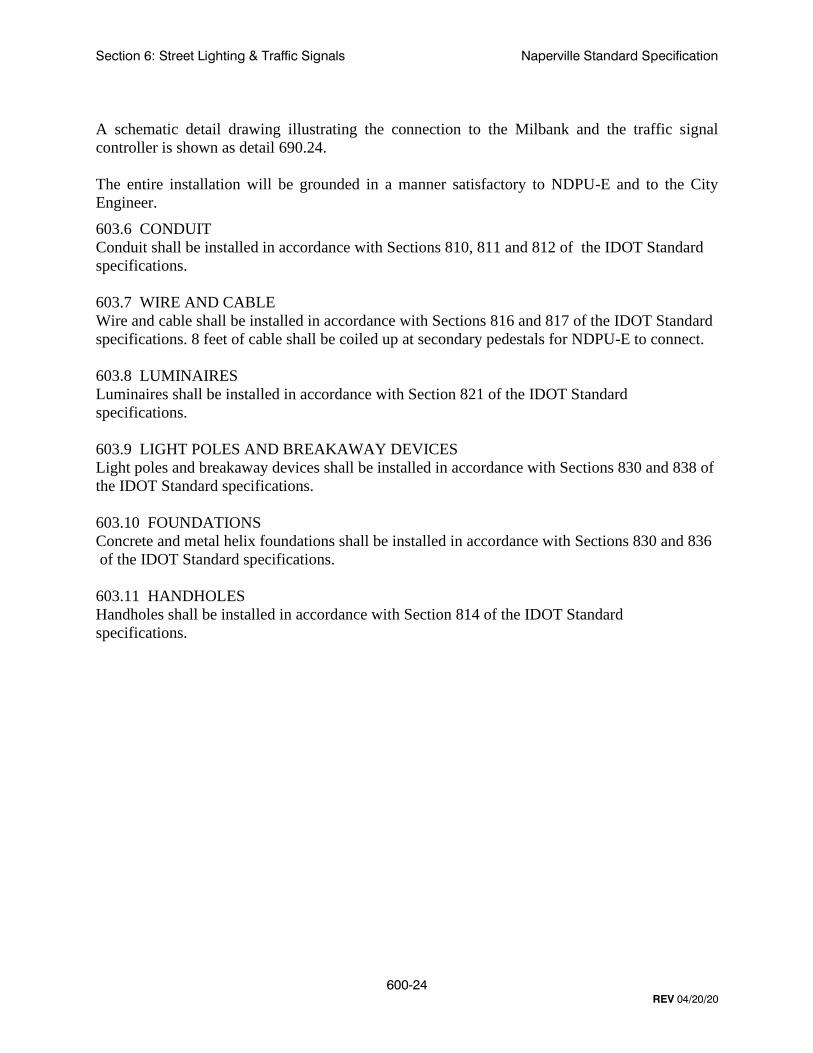
A schematic detail drawing illustrating the connection to the Milbank and the traffic signal
controller is shown as detail 690.24.
The entire installation will be grounded in a manner satisfactory to NDPU-E and to the City
Engineer.
603.6 CONDUIT
Conduit shall be installed in accordance with Sections 810, 811 and 812 of the IDOT Standard
specifications.
603.7 WIRE AND CABLE
Wire and cable shall be installed in accordance with Sections 816 and 817 of the IDOT Standard
specifications. 8 feet of cable shall be coiled up at secondary pedestals for NDPU-E to connect.
603.8 LUMINAIRES
Luminaires shall be installed in accordance with Section 821 of the IDOT Standard
specifications.
603.9 LIGHT POLES AND BREAKAWAY DEVICES
Light poles and breakaway devices shall be installed in accordance with Sections 830 and 838 of
the IDOT Standard specifications.
603.10 FOUNDATIONS
Concrete and metal helix foundations shall be installed in accordance with Sections 830 and 836
of the IDOT Standard specifications.
603.11 HANDHOLES
Handholes shall be installed in accordance with Section 814 of the IDOT Standard
specifications.

Section 6: Street Lighting & Traffic Signals Naperville Standard Specification
600-25
REV 04/20/20
604 INSPECTIONS AND TESTING
604.1 STREET LIGHTING SYSTEMS
New or reinstalled street lights must be inspected by the city’s Inspection Team prior to electrical
hook-up and before their acceptance. The contractor should contact the Transportation,
Engineering and Development Business Group Inspection Dispatch at (630) 420-6082 to schedule
an inspection. The inspection must be scheduled at least 72 hours in advance. Testing shall be in
accordance with article 801.13(a) of the IDOT Standard specifications. Upon initial inspection
approval, the contractor should then call City Dispatch at (630) 420-6187 to schedule an electrical
hook-up with NDPU-E. The request must be scheduled at least 72 hours in advance. Once
energized the contractor should call City Dispatch to schedule a night run inspection for final
acceptance.
604.2 TRAFFIC SIGNAL SYSTEMS
604.2.1 CONCRETE
All concrete work associated with the installation of a traffic signal must be tested by the
contractor. Test results shall be provided to City indicating specified strength at 14 days meets
IDOT requirements for class SI concrete.
604.2.2 FIELD INSPECTION
A field inspection is required prior to maintenance transfer of a signal from the contractor to the
city. It is the intent to have all electrical work completed and equipment field tested by the
vendor prior to the city's "turn-on" field inspection. If in the event the City Engineer determines
work is not complete and the inspection will require more than two hours to complete, the
inspection shall be cancelled and the contractor will be required to reschedule at another date.
The maintenance of the traffic signals will not be accepted until all punch list work is corrected
and re-inspected.
When the road is open to traffic, except as otherwise provided in the IDOT Special Provisions,
the contractor may request a turn-on and inspection of the completed traffic signal installation at
each separate location. This request must be made to the City Engineer at (630) 420-6100 a
minimum of 7 working days prior to the time of the requested inspection. The city will not grant
a field inspection until written certification is provided by the contractor and the equipment has
been field tested and the intersection is operating according to contract requirements.
Section 6: Street Lighting & Traffic Signals Naperville Standard Specification
600-26
REV 04/20/20
690 STANDARD DETAILS
Structures
690.01 Davit Arm Street Light Detail – 23 Foot
690.02 Davit Arm Street Light Detail – 32 Foot
690.03 Twin Davit Arm Street Light Detail – 32 Foot
690.04 Truss Arm Street Light Detail – 32 Foot
690.05 Twin Truss Arm Street Light Detail – 32 Foot
690.06 Truss Arm Street Light Detail – 40 Foot
690.07 Truss Arm Street Light Detail – 47.5 Foot
690.08 Twin Truss Arm Street Light Detail – 47.5 Foot
690.09 Caged Acorn Street Light Detail – 10 Foot (CBD Only)
690.10 Side Mount Street Light Detail – 30 Foot (CBD Only)
690.11 Light Pole and Controller Labeling Detail
690.12 Metal Helix Pole Foundation Detail (2 Sheets)
690.13 Concrete Pole Foundation Detail – 18 Inch Diameter (CBD Only) (2 Sheets)
690.14 Concrete Pole Foundation Detail – 24 Inch Diameter (2 Sheets)
690.15 Offset Concrete Pole Foundation Detail – 24 Inch Diameter (2 Sheets)
690.16 Breakaway Transformer Base Detail
690.17 Cast-in Place Concrete Handhole Detail
690.18 Composite Concrete Handhole Detail
Electrical
690.21 Street Lighting Controller Details– 100A (3 sheets)
690.22 Holiday Lighting Controller Details– 225A (3 Sheets) (CBD Only)
690.23 Typical Street Light Connection Detail (3 Sheets)
690.24 Service Connections
Conduit & Trenching
690.30 Typical Trench Detail
690.99 COMMON NAMES
All standard details in this section may be referred to by a common name in associated construction
documents. The common name shall be “LIGHTING xx” where the xx is the section of the detail
number to the right of the decimal point. For instance, Detail #690.01 DAVIT ARM STREET
LIGHT DETAIL – 23 FOOT may also be referred to as “LIGHTING 1”.

TRAFFIC FLOW
60
HANDHOLE MAST ARM
POLE
(5.5' TO TOP)DETAIL 690.11POLE IDENTIFICATION
90
POLE SHAFT
HANDHOLE
CONDUCTORLUG FOR GROUNDING HOLE FOR GROUND 3/8" - 16 TAPPED BOLT
690.01
DAVIT ARM STREET LIGHT
DETAIL - 23 FOOT
LIGHTING 1City of Naperville
STANDARDDETAIL
EFFECTIVE: 4/20/2020 SHEET 1 OF 1
1.
2.
3.
R4'-0"
23'
M.H.
17'-8" P
OLE S
HA
FT
1'-6"
9"
MINIMUM
10 1/2"
10 1/2"
4 1/2" O.D.
ALLOY 356-T6
TRANSFORMER BASE
GRADE
CURB
6'-6"
8'-0"
10"
2"
1'-2"
4"X6" HANDHOLE & COVER
EPA OF 1.6 SQ. FT. AND WEIGHING 75 LBS.
POLE DESIGN MEETS LATEST AASHTO SPECIFICATION FOR 90 MPH WIND WITH A LUMINAIRE HAVING A MAXIMUM
POLE IS UL CLASSIFIED WITH UL LABEL AND HANDHOLE COVER GASKET COMPLYING WITH UL 1572.
COMPLETE ASSEMBLY POWDER COATED TEXTURED DARK BRONZE, HAPCO, VALMONT OR APPROVED EQUAL.
NOTES:
5'
NOTES:
7-PIN TWIST LOCK RECEPTACLE
FOR LUMINAIRE MANUFACTURER & MODEL NUMBER)PUBLIC IMPROVEMENTS SECTION 4.5 STREET LIGHTING" COBRAHEAD TYPE LUMINAIRE (SEE "DESIGN MANUAL FOR
HEX. NUTS AND WASHERS
STEEL HEX. HD. BOLTS WITH
(2) 1/2"-13NC STAINLESS
(INSTALLED)
INTERNAL DAMPER
CIRCLE
10"-11" BOLT
1 41
" X 2" BOLT
SLOT HOLE
TENON
2 3/8" O.D.
CONDITIONS WARRANT)SUBSTITUTED IF SOIL 690.14, MAY BE FOUNDATION, DETAIL (A CONCRETE DETAIL 690.12 FOUNDATION PER METAL HELIX
SCREWS
HEX HEAD SOCKET
1/4"-20NC S.S.
BOLT COVERS AND
FINISH (100 GRIT)
6063-T6 SATIN GROUND
(7" TO 4 1/2"), 0.219" WALL
TAPERED ALUMINUM SHAFT
HANDHOLE ORIENTATION
HANDHOLE DETAIL
BASE PLATE
MAST ARM &

TRAFFIC FLOW
60
HANDHOLE MAST ARM
POLE
(5.5' TO TOP)DETAIL 690.11POLE IDENTIFICATION
90
POLE SHAFT
HANDHOLE
CONDUCTORLUG FOR GROUNDING HOLE FOR GROUND 3/8" - 16 TAPPED BOLT
690.02
DAVIT ARM STREET LIGHT
DETAIL - 32 FOOT
LIGHTING 2City of Naperville
STANDARDDETAIL
EFFECTIVE: 4/20/2020 SHEET 1 OF 1
1.
ALLOY 356-T6
32'
M.H.
R5'-0"
4 1/2" O.D.
10'-0"
TRANSFORMER BASE
GRADE
CURB
6'-6"
10"
2"
1'-2"
9"
12"
12"
MINIMUM
4"X6" HANDHOLE & COVER
26'-8" P
OLE S
HA
FT
1'-6"
5"
2.
3.
NOTES:
EPA OF 1.6 SQ. FT. AND WEIGHING 75 LBS.
POLE DESIGN MEETS LATEST AASHTO SPECIFICATION FOR 90 MPH WIND WITH A LUMINAIRE HAVING A MAXIMUM
POLE IS UL CLASSIFIED WITH UL LABEL AND HANDHOLE COVER GASKET COMPLYING WITH UL 1572.
COMPLETE ASSEMBLY POWDER COATED TEXTURED DARK BRONZE, HAPCO, VALMONT OR APPROVED EQUAL.
7-PIN TWIST LOCK RECEPTACLE
FOR LUMINAIRE MANUFACTURER & MODEL NUMBER)PUBLIC IMPROVEMENTS SECTION 4.5 STREET LIGHTING" COBRAHEAD TYPE LUMINAIRE (SEE "DESIGN MANUAL FOR
HEX. NUTS AND WASHERS
STEEL HEX. HD. BOLTS WITH
(2) 1/2"-13NC STAINLESS
FINISH (100 GRIT)
6063-T6 SATIN GROUND
(8" TO 4 1/2"), 0.219" WALL
TAPERED ALUMINUM SHAFT
(INSTALLED)
INTERNAL DAMPER
CIRCLE11"-12" BOLT
1 41
" X 2" BOLT
SLOT HOLE
TENON
2 3/8" O.D.
CONDITIONS WARRANT)SUBSTITUTED IF SOIL 690.14, MAY BE FOUNDATION, DETAIL (A CONCRETE DETAIL 690.12 FOUNDATION PER METAL HELIX
SCREWS
HEX HEAD SOCKET
1/4"-20NC S.S.
BOLT COVERS AND
HANDHOLE ORIENTATION
MAST ARM &
BASE PLATE
HANDHOLE DETAIL

HANDHOLE
10'-0"
32'
M.H.
R5'-0"
4 1/2" O.D.
TRANSFORMER BASE
GRADE
CURB
MINIMUM
9"
10"
2"
1'-2"
4"X6" HANDHOLE & COVER
7-PIN TWIST LOCK RECEPTACLE
6'-6"
1'-6"
26'-8" P
OLE S
HA
FT
MANUFACTURER & MODEL NUMBER)LIGHTING" FOR LUMINAIRE IMPROVEMENTS SECTION 4.5 STREET "DESIGN MANUAL FOR PUBLIC COBRAHEAD TYPE LUMINAIRE (SEE
5" (NOTE 4)
(INSTALLED)
INTERNAL DAMPER
HEX. NUTS AND WASHERS
STEEL HEX. HD. BOLTS WITH
(2) 1/2"-13NC STAINLESS
CONDITIONS WARRANT)SUBSTITUTED IF SOIL 690.14, MAY BE FOUNDATION, DETAIL (A CONCRETE DETAIL 690.12 FOUNDATION PER METAL HELIX
FINISH (100 GRIT)
6063-T6 SATIN GROUND
(8" TO 4 1/2"), 0.219" WALL
TAPERED ALUMINUM SHAFT
TENON
2 3/8" O.D
POLE
MAST ARM
POLE I.D.
(5.5' TO TOP)DETAIL 690.11POLE IDENTIFICATION
60°
60°
TRAFFIC FLOW
TRAFFIC FLOW
POLE SHAFT
HANDHOLE
CONDUCTORLUG FOR GROUNDING HOLE FOR GROUND 3/8" - 16 TAPPED BOLT
690.03
TWIN DAVIT ARM STREET
LIGHT DETAIL - 32 FOOT
LIGHTING 3City of Naperville
STANDARDDETAIL
EFFECTIVE: 4/20/2020 SHEET 1 OF 1
ALLOY 356-T6
12"
12"
HANDHOLE ORIENTATION
1.
2.
3.
NOTES:
FOR MEDIAN LOCATIONS POLE SHALL BE IN CENTER OF MEDIAN.
EPA OF 1.6 SQ. FT. AND WEIGHING 75 LBS.
POLE DESIGN MEETS LATEST AASHTO SPECIFICATION FOR 90 MPH WIND WITH A LUMINAIRE HAVING A MAXIMUM
POLE IS UL CLASSIFIED WITH UL LABEL AND HANDHOLE COVER GASKET COMPLYING WITH UL 1572.
COMPLETE ASSEMBLY POWDER COATED TEXTURED DARK BRONZE, HAPCO, VALMONT OR APPROVED EQUAL.
4.
1 41
" X 2" BOLT
SLOT HOLE
CIRCLE11"-12" BOLT
SCREWS
HEX HEAD SOCKET
1/4"-20NC S.S.
BOLT COVERS AND
MAST ARM &
HANDHOLE DETAIL
BASE PLATE
TRAFFIC FLOW
60
HANDHOLE MAST ARM
POLE
(5.5' TO TOP)DETAIL 690.11POLE IDENTIFICATION
90
POLE SHAFT
HANDHOLE
CONDUCTORLUG FOR GROUNDING HOLE FOR GROUND 3/8" - 16 TAPPED BOLT
690.04
TRUSS ARM STREET LIGHT
DETAIL - 32 FOOT
LIGHTING 4City of Naperville
STANDARDDETAIL
EFFECTIVE: 4/20/2020 SHEET 1 OF 1
MINIMUM
BASETRANSFORMER
GRADE
CURB
GROUND FINISH (100 GRIT)WALL 6063-T6 SATIN SHAFT (8" TO 6"), 0.219" TAPERED ALUMINUM
12" ALLOY 356-T6
9"
29'-8" P
OLE S
HA
FT
6"
5'
1'-9"
1.
NOTES:
EPA OF 1.6 SQ. FT. AND WEIGHING 75 LBS.
POLE DESIGN MEETS LATEST AASHTO SPECIFICATION FOR 90 MPH WIND WITH A LUMINAIRE HAVING A MAXIMUM
RISE OF LUMINAIRE ARM IS 34".
POLE IS UL CLASSIFIED WITH UL LABEL AND HANDHOLE COVER GASKET COMPLYING WITH UL 1572.
LUMINAIRE ATTACHED TO POLE WITH CLAMP BRACKET & 1/2" X 13" N.C. S.S. HARDWARE.
MOUNTED HEIGHT FROM TENON TO POLE ANCHOR PLATE.
COMPLETE ASSEMBLY NATURAL SATIN FINISH WITH 5 YEAR WARRANTY. HADCO, VALMONT OR APPROVED EQUAL.
NOTES:
2.
3.
4.
5.
6.
7-PIN TWIST LOCK RECEPTACLE
FOR LUMINAIRE MANUFACTURER & MODEL NUMBER)PUBLIC IMPROVEMENTS SECTION 4.5 STREET LIGHTING" COBRAHEAD TYPE LUMINAIRE (SEE "DESIGN MANUAL FOR
CONDITIONS WARRANT)SUBSTITUTED IF SOIL 690.14, MAY BE FOUNDATION, DETAIL (A CONCRETE DETAIL 690.12 FOUNDATION PER METAL HELIX
11"-12" BOLT CIRCLE
32'
M.H.
NO
TE 2
TUBETAPERED ALUMINUM
DAMPERINTERNAL VIBRATION
POLE CAPCAST ALUMINUM
12"
SLOT HOLE1 1/4"X2" BOLT
1'-6"
10'-0"
& COVER4"X6" HANDHOLE
TENON2 3/8" O.D.
HANDHOLE ORIENTATION
MAST ARM &
BASE PLATE
HANDHOLE DETAIL

HANDHOLE
POLE
MAST ARM
POLE I.D.
(5.5' TO TOP)DETAIL 690.11POLE IDENTIFICATION
60°
60°
TRAFFIC FLOW
TRAFFIC FLOW
POLE SHAFT
HANDHOLE
CONDUCTORLUG FOR GROUNDING HOLE FOR GROUND 3/8" - 16 TAPPED BOLT
1.
NOTES:
EPA OF 1.6 SQ. FT. AND WEIGHING 75 LBS.
POLE DESIGN MEETS LATEST AASHTO SPECIFICATION FOR 90 MPH WIND WITH A LUMINAIRE HAVING A MAXIMUM
RISE OF LUMINAIRE ARM IS 34".
POLE IS UL CLASSIFIED WITH UL LABEL AND HANDHOLE COVER GASKET COMPLYING WITH UL 1572.
LUMINAIRE ATTACHED TO POLE WITH CLAMP BRACKET & 1/2" X 13" N.C. S.S. HARDWARE.
MOUNTED HEIGHT FROM TENON TO POLE ANCHOR PLATE.
COMPLETE ASSEMBLY NATURAL SATIN FINISH WITH 5 YEAR WARRANTY. HADCO, VALMONT OR APPROVED EQUAL.
NOTES:
2.
3.
4.
5.
6.
CURB
GROUND FINISH (100 GRIT)WALL 6063-T6 SATIN SHAFT (8" TO 6"), 0.219" TAPERED ALUMINUM
12" ALLOY 356-T6
1'-9"
CONDITIONS WARRANT)SUBSTITUTED IF SOIL 690.14, MAY BE FOUNDATION, DETAIL (A CONCRETE DETAIL 690.12 FOUNDATION PER METAL HELIX
690.05
LIGHTING 5City of Naperville
STANDARDDETAIL
EFFECTIVE: 4/20/2020 SHEET 1 OF 1
11"-12" BOLT CIRCLE
32'
M.H.
NO
TE 2
MINIMUM
TUBETAPERED ALUMINUM
DAMPERINTERNAL VIBRATION
BASETRANSFORMER
GRADE
12"
SLOT HOLE1 1/4"X2" BOLT
9"
1'-6"
29'-8" P
OLE S
HA
FT
6"
5'
10'-0"
& COVER4"X6" HANDHOLE
TENON2 3/8" O.D.
POLE CAPCAST ALUMINUM
TWIN TRUSS ARM STREET LIGHT
DETAIL - 32 FOOT
FOR LUMINAIRE MANUFACTURER & MODEL NUMBER)PUBLIC IMPROVEMENTS SECTION 4.5 STREET LIGHTING" COBRAHEAD TYPE LUMINAIRE (SEE "DESIGN MANUAL FOR
RECEPTACLE7-PIN TWIST LOCK
HANDHOLE ORIENTATION
MAST ARM &
BASE PLATE
HANDHOLE DETAIL
TRAFFIC FLOW
60
HANDHOLE MAST ARM
POLE
(5.5' TO TOP)DETAIL 690.11POLE IDENTIFICATION
90
POLE SHAFT
HANDHOLE
CONDUCTORLUG FOR GROUNDING HOLE FOR GROUND 3/8" - 16 TAPPED BOLT
690.06
TRUSS ARM STREET LIGHT
DETAIL - 40 FOOT
LIGHTING 6City of Naperville
STANDARDDETAIL
EFFECTIVE: 4/20/2020 SHEET 1 OF 1
37'-8" P
OLE S
HA
FT
9"
MINIMUM
5'
CURB
BASETRANSFORMER
14"
14"
SLOT HOLE1 1/4"X2" BOLT
ALLOY 356-T6
1'-9"
1.
NOTES:
EPA OF 1.6 SQ. FT. AND WEIGHING 75 LBS.
POLE DESIGN MEETS LATEST AASHTO SPECIFICATION FOR 90 MPH WIND WITH A LUMINAIRE HAVING A MAXIMUM
RISE OF LUMINAIRE ARM IS 34".
POLE IS UL CLASSIFIED WITH UL LABEL AND HANDHOLE COVER GASKET COMPLYING WITH UL 1572.
LUMINAIRE ATTACHED TO POLE WITH CLAMP BRACKET & 1/2" X 13" N.C. S.S. HARDWARE.
MOUNTED HEIGHT FROM TENON TO POLE ANCHOR PLATE.
COMPLETE ASSEMBLY NATURAL SATIN FINISH WITH 5 YEAR WARRANTY. HADCO, VALMONT OR APPROVED EQUAL.
NOTES:
2.
3.
4.
5.
6.
BOLT CIRCLE14 1/2" - 15 1/2"
7-PIN TWIST LOCK RECEPTACLE
FOR LUMINAIRE MANUFACTURER & MODEL NUMBER)PUBLIC IMPROVEMENTS SECTION 4.5 STREET LIGHTING" COBRAHEAD TYPE LUMINAIRE (SEE "DESIGN MANUAL FOR
CONDITIONS WARRANT)SUBSTITUTED IF SOIL 690.14, MAY BE FOUNDATION, DETAIL (A CONCRETE DETAIL 690.12 FOUNDATION PER METAL HELIX
POLE CAPCAST ALUMINUM
1'-6" GRADE
TUBETAPERED ALUMINUM
DAMPERINTERNAL VIBRATION
GROUND FINISH (100 GRIT)WALL 6063-T6 SATIN SHAFT (8" TO 6"), 0.250" TAPERED ALUMINUM
40'
M.H.
NO
TE 2
6"
& COVER4"X8" HANDHOLE
12'-0"
TENON2 3/8" O.D.
HANDHOLE ORIENTATION
MAST ARM &
HANDHOLE DETAIL
BASE PLATE
TRAFFIC FLOW
60
HANDHOLE MAST ARM
POLE
(5.5' TO TOP)DETAIL 690.11POLE IDENTIFICATION
90
POLE SHAFT
HANDHOLE
CONDUCTORLUG FOR GROUNDING HOLE FOR GROUND 3/8" - 16 TAPPED BOLT
690.07
TRUSS ARM STREET LIGHT
DETAIL - 47.5 FOOT
LIGHTING 7City of Naperville
STANDARDDETAIL
EFFECTIVE: 4/20/2020 SHEET 1 OF 1
14" ALLOY 356-T6
BASETRANSFORMER
6"
1'-9"
7-PIN TWIST LOCK RECEPTACLE
1.
NOTES:
EPA OF 1.6 SQ. FT. AND WEIGHING 75 LBS.
POLE DESIGN MEETS LATEST AASHTO SPECIFICATION FOR 90 MPH WIND WITH A LUMINAIRE HAVING A MAXIMUM
RISE OF LUMINAIRE ARM IS 34".
POLE IS UL CLASSIFIED WITH UL LABEL AND HANDHOLE COVER GASKET COMPLYING WITH UL 1572.
LUMINAIRE ATTACHED TO POLE WITH CLAMP BRACKET & 1/2" X 13" N.C. S.S. HARDWARE.
MOUNTED HEIGHT FROM TENON TO POLE ANCHOR PLATE.
COMPLETE ASSEMBLY NATURAL SATIN FINISH WITH 5 YEAR WARRANTY. HADCO, VALMONT OR APPROVED EQUAL.
NOTES:
2.
3.
4.
5.
6.
FOR LUMINAIRE MANUFACTURER & MODEL NUMBER)PUBLIC IMPROVEMENTS SECTION 4.5 STREET LIGHTING" COBRAHEAD TYPE LUMINAIRE (SEE "DESIGN MANUAL FOR
DETAIL 690.14FOUNDATION, CONCRETE
GROUND FINISH (100 GRIT)WALL 6063-T6 SATIN SHAFT (10" TO 6"), 0.312" TAPERED ALUMINUM
NO
TE 2
14"
SLOT HOLE1 1/4"X2" BOLT
5'
MINIMUM
1'-6"
45'-2" P
OLE S
HA
FT
9"
GRADE
CURB
TUBETAPERED ALUMINUM
DAMPERINTERNAL VIBRATION
POLE CAPCAST ALUMINUM
47.5'
M.H.
BOLT CIRCLE14 1/2"-15 1/2"
& COVER4"X8"HANDHOLE
12'-0"
TENON2 3/8" O.D.
HANDHOLE ORIENTATION
MAST ARM &
HANDHOLE DETAIL
BASE PLATE

HANDHOLE
POLE
MAST ARM
POLE I.D.
(5.5' TO TOP)DETAIL 690.11POLE IDENTIFICATION
60°
60°
TRAFFIC FLOW
TRAFFIC FLOW
POLE SHAFT
HANDHOLE
CONDUCTORLUG FOR GROUNDING HOLE FOR GROUND 3/8" - 16 TAPPED BOLT
14" ALLOY 356-T6
1'-9"
690.08
TWIN TRUSS ARM STREET
LIGHT DETAIL - 47.5 FOOT
LIGHTING 8City of Naperville
STANDARDDETAIL
EFFECTIVE: 4/20/2020 SHEET 1 OF 1
45'-2" P
OLE S
HA
FT
9"
1'-6"
14"
SLOT HOLE1 1/4"X2" BOLT
BOLT CIRCLE14 1/2"-15 1/2"
GRADE
CURB
BASETRANSFORMER
GROUND FINISH (100 GRIT)WALL 6063-T6 SATIN SHAFT (10" TO 6"), 0.312" TAPERED ALUMINUM
DAMPERINTERNAL VIBRATION
NO
TE 2
47.5'
M.H.
POLE CAPCAST ALUMINUM
6"
TUBETAPERED ALUMINUM
& COVER4"X8" HANDHOLE
12'-0"
1.
NOTES:
EPA OF 1.6 SQ. FT. AND WEIGHING 75 LBS.
POLE DESIGN MEETS LATEST AASHTO SPECIFICATION FOR 90 MPH WIND WITH A LUMINAIRE HAVING A MAXIMUM
RISE OF LUMINAIRE ARM IS 34".
POLE IS UL CLASSIFIED WITH UL LABEL AND HANDHOLE COVER GASKET COMPLYING WITH UL 1572.
LUMINAIRE ATTACHED TO POLE WITH CLAMP BRACKET & 1/2" X 13" N.C. S.S. HARDWARE.
MOUNTED HEIGHT FROM TENON TO POLE ANCHOR PLATE.
COMPLETE ASSEMBLY NATURAL SATIN FINISH WITH 5 YEAR WARRANTY. HADCO, VALMONT OR APPROVED EQUAL.
NOTES:
2.
3.
4.
5.
6.
FOR LUMINAIRE MANUFACTURER & MODEL NUMBER)PUBLIC IMPROVEMENTS SECTION 4.5 STREET LIGHTING" COBRAHEAD TYPE LUMINAIRE (SEE "DESIGN MANUAL FOR
HANDHOLE ORIENTATION
RECEPTACLE7-PIN TWIST LOCK
DETAIL 690.14FOUNDATION, CONCRETE
TENON2 3/8" O.D.
MAST ARM &
BASE PLATE
HANDHOLE DETAIL

TRAFFIC FLOW
45
HANDHOLE
POLE
(1'-0" TO TOP)DETAIL 690.11POLE IDENTIFICATION
690.09
LIGHTING 9City of Naperville
STANDARDDETAIL
EFFECTIVE: 4/20/2020 SHEET 1 OF 1
MINIMUM
STREET SIDE
10'-0"
9'-0"
27"
3" SLIP FITTER
RECEPTACLEHANDHOLE &
GRADE
2'
12"
COVERHANDHOLE &
CAGED ACORN STREET LIGHT
DETAIL- 10 FOOT (CBD ONLY)
CURB
TOP LENSDIFFUSED ACRYLIC
GLOBECLEAR ACRYLIC
MANUFACTURER & MODEL NUMBER)LIGHTING" FOR LUMINAIRE IMPROVEMENTS SECTION 4.5 STREET (SEE "DESIGN MANUAL FOR PUBLIC TYPE LUMINAIRE WITH SOLID ROOF CAST ALUMINUM CAGED ACORN
POLYCARBONATE COVERWITH CLEAR IN-USE RATED 20A-120V GFCI-W.R. RECEPTACLE
ABT (3" TENON)POLE #DB9-4F10-188-TEN3-BL-RBC-ARCHITECTURAL AREA LIGHTING POLE PAINTED BLACK 0.188" WALL 4" DIAMETER FLUTED ALUMINUM
TWIST LOCK RECEPTACLE ACRYLIC CUPOLA WITH 7-PIN
APART8 3/4" DIA. 120° BOLT CIRCLE:
ENTIRE BASEGROUT UNDER
TYP. OF 4MEDALLIONS, LOGO CAST INTO CUSTOM NAPERVILLE
DETAIL 690.13FOUNDATIONCONCRETE
LONG TENONPOLE WITH 3" O.D. x 3.3"
HANDHOLE ORIENTATION
BASE PLATE
MEDALLION LOGO
AREACUTOUT
AREASOLID

TRAFFIC FLOW
60
HANDHOLE MAST ARM
POLE
(5.5' TO TOP)DETAIL 690.11POLE IDENTIFICATION
90
POLE SHAFT
HANDHOLE
CONDUCTORLUG FOR GROUNDING HOLE FOR GROUND 3/8" - 16 TAPPED BOLT
690.10
City of Naperville
STANDARDDETAIL
EFFECTIVE: 4/20/2020 SHEET 1 OF 1
DETAIL - 30 FOOT (CBD ONLY)SIDE MOUNT STREET LIGHT
9"
1'-6"
30'
MO
UN
TIN
G H
EIG
HT
UNIVERSAL ARM MOUNT
(INSTALLED)INTERNAL DAMPER
GROUND FINISH (100 GRIT)(10" TO 6"), 0.250" WALL 6063-T6 SATIN ROUND TAPERED ALUMINUM SHAFT
POLYCARBONATE COVERWITH CLEAR IN-USE RATED 20A-120V GFCI-W.R. RECEPTACLE
TRANSFORMER BASE
HEX HEAD SOCKET SCREWSBOLT COVERS AND 1/4" 20NC S.S.
GRADE
CURB
1.
14"-15" BOLT CIRCLE
14"
14"
SLOT HOLE1 1/2"X2" BOLT
ALLOY 356-T6
9'-0"
MINIMUM
5'
4"X6" HANDHOLE & COVER
1 1/4" THICK
7-PIN TWIST LOCK RECEPTACLEPOLE CAP
MANUFACTURER & MODEL NUMBER)LIGHTING" FOR LUMINAIRE IMPROVEMENTS SECTION 4.5 STREET MANUAL FOR PUBLIC AREA TYPE LUMINAIRE (SEE "DESIGN
2.
3.
4.
NOTES:
A MAXIMUM EPA OF 1.6 SQ. FT. AND WEIGHING 75 LBS.
POLE DESIGN MEETS LATEST AASHTO SPECIFICATION FOR 90 MPH WIND WITH A LUMINAIRE HAVING
LUMINAIRE IS ATTACHED TO POLE WITH UNIVERSAL ARM MOUNT.
POLE IS UL CLASSIFIED WITH UL LABEL AND HANDHOLE COVER GASKET COMPLYING WITH UL 1572.
WITH 5 YEAR WARRANTY.
COMPLETE ASSEMBLY POWDER COATED TEXTURED BLACK HADCO, VALMONT, OR APPROVED EQUAL
NOTES:
DETAIL 690.14FOUNDATION CONCRETE
LIGHTING 10
HANDHOLE ORIENTATION
HANDHOLE DETAIL
MAST ARM &
BASE PLATE

690.11
LIGHTING 11City of Naperville
STANDARDDETAIL
EFFECTIVE: 4/20/2020 SHEET 1 OF 1
LIGHT POLE AND CONTROLLER
LABELING DETAIL
0
8
4
2
1
5
0
8
4
2
1
5
065ACity of Naperville
3"
9"
2"
3/8"
10"
E/G WHITE
7725-12 BLACK
17"
E/G WHITE
E/G RED
LIGHTING CONTROLLER LABEL (BACK OF CABINET)
TYPICAL LIGHT POLE LABEL
NOTES:
1.
NOTES:
2.
3. SEE POLE AND CONTROLLER DETAILS FOR LOCATION OF LABELS.
COORDINATE LABEL NUMBERS WITH THE CITY.
ALL LABELS SHALL BE WESTERN REMAC OR APPROVED EQUAL.
E/G WHITE7725-12 BLACK
1 1/8"
1 1/8"
3/8"
7/8"
3/8"
BLACK7725-12
3/4"
1 1/2"
1/2"
E/G RED
2 1/2"
2 1/2"
CBD LIGHT POLE LABEL
2"
3"
1 1/2"
1 1/4"
2"
1 1/8"
1 5/8"

690.12
HELIX TYPE POLE
FOUNDATION DETAIL
LIGHTING 12City of Naperville
STANDARDDETAIL
EFFECTIVE: 4/20/2020 SHEET 1 OF 2
SH
AF
T L
EN
GT
H
15"
BASEPLATE
23 FT 5.0 FT
6.0 FT
HELIX FOUNDATION SIZE
6.0 FT 15"X15"X1 1/4"
32 FT
40 FT
12"X12"X1"
PILOT
HELIX
ITEM MATERIAL REQUIREMENT
SHAFT
AASHTO M 270 (ASTM A 575)
AASHTO M 183 (ASTM A 635)
AASHTO M 314 (ASTM F 1554)
AASHTO M 293 (ASTM F 436)WASHERS
HELIX FOUNDATION MATERIALS
HELIX SCREW
PILOT POINT
ANCHOR RODS/STUDS
HEXAGON NUTS
BASE PLATE
ASTM A 252, GRADE 2 (PHOSPHOROUS 0.04% MAXIMUM, SULFUR 0.05% MAXIMUM)
AASHTO M 270M, GRADE 36 (M270M, GRADE 250)
2HAASHTO M 291M (ASTM A 563) GRADE DH, OR AASHTO M 292 (ASTM A 194) GRADE
8 5/8"10 1/2"
BASE PLATE (SEE TABLE)
BOLT CIRCLE (SEE TABLE)
1"
1"
1"
DIAMETER SHAFT
11 1/2" 8 5/8"
8 5/8"15"
HEIGHTPOLE
CIRCLEBOLT
DIA.SHAFT
SIZEBOLT
LENGTHSHAFT
ELEVATION
PLAN
12"X12"X1"
SHAFT
0.25" WALL
(2 AT 180°)2 1/2"X18" CONDUIT
FOR STUD SIZE)PLATE (SEE TABLE 2 3/4" ABOVE TOP OF SHALL PROTRUDE WITH JAM NUT, STUD (4) THREADED STUDS
1"-2" ABOVE FINISH GRADETOP OF PLATE SHALL BE

690.12
HELIX TYPE POLE
FOUNDATION DETAIL
LIGHTING 12City of Naperville
STANDARDDETAIL
EFFECTIVE: 4/20/2020 SHEET 2 OF 2
NOTES:
1.
2.
3.
4.
5.
6.
7.
8.
9.
10.
11.MANUFACTURE.BASE PLATE SHALL BE PERMANENTLY STAMPED WITH MANUFACTURUER'S NAME AND DATE OF
PILOT POINT AND SHAFT AXES TO BE CONCENTRIC (± 125) AND IN LINE (± 2 DEG).
(± 0.188) TO THE SHAFT AXIS.BASE PLATE TO BE PERPENDICULAR TO SHAFT AXIS (± 1 DEG) AND HOLE CENTERLINE CONCENTRIC
CONCRETE FOUNDATION.DO NOT ACHIEVE THE MINIMUM INTALLATION TORQUE SHALL BE REMOVED AND REPLACE WITH A THAN 3,500 FT LB. METAL FOUNDATIONS THAT ARE NOT INSTALLED TO FULL INSTALLATION DEPTH OR MAXIMUM TORQUE RATING NOR SHALL IT BE INSTALLED TO AN INSTALLATION TORQUE VALUE OF LESS THE METAL FOUNDATION SHALL NOT BE INSTALLED TO A TORQUE WHICH EXCEEDS THE MANUFACTURER'S
BACK FILLING AROUND THE FOUNDATION IS NOT ALLOWED.METAL FOUNDATIONS SHALL BE INSTALLED IN UNDISTURBED SOIL. PREDRILLING A PILOT HOLE AND/OR
ANY VOIDS WITHIN THE METAL FOUNDATION SHALL BE FILLED WITH FINE AGGREGATE.
WITH THE BREAKAWAY DEVICE MANUFACTURER'S REQUIREMENTS.THE CONTRACTOR SHALL COORDINATE EXTENSION OF ANCHOR BOLTS ABOVE TOP OF THE BASE PLATE
LIGHT POLE. THE CABLE TRENCH SHALL BE BACKFILLED AND FIRMLY COMPACTED BEFORE THE INSTALLATION OF THE
THE HELIX FOUNDATION SHAFT SHALL BE INSTALLED PLUMB AND THE BASE PLATE SHALL BE IN LEVEL.
AXIS OF THE FOUNDATION.SHALL BE CAPABLE OF WITHSTANDING 10,000 FT/LBS OF INSTALLATION TORQUE APPLIED ABOUT THE ALL WELDS SHALL BE CONTINUOUS AND NOT LESS THAN 1/4" FILLET WELDS. THE WELDED FOUNDATION
ALL MATERIALS SHALL BE GALVANIZED ACCORDING TO AASHTO M 111 (LATEST REVISION).
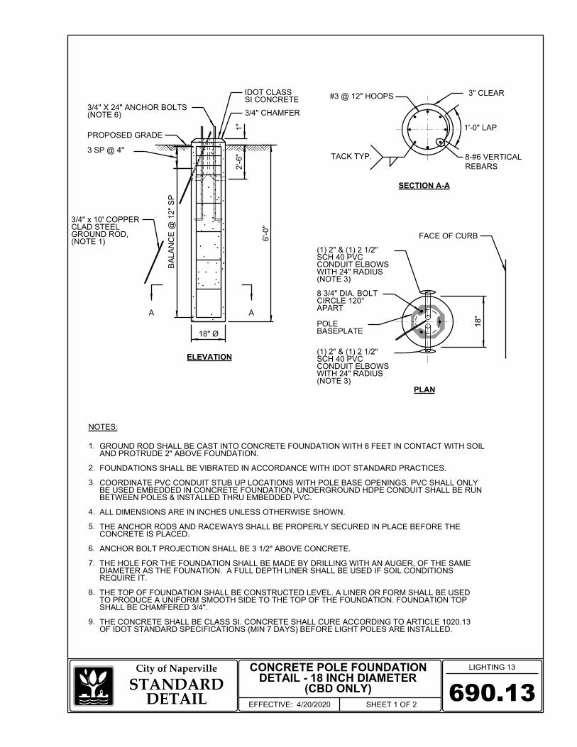
690.13
LIGHTING 13City of Naperville
STANDARDDETAIL
EFFECTIVE: 4/20/2020 SHEET 1 OF 2
ELEVATION
SECTION A-A
3 SP @ 4"
6'-0"
BA
LA
NC
E @ 1
2" S
P
2'-6"
(NOTE 6)3/4" X 24" ANCHOR BOLTS
18" Ø
(NOTE 1)GROUND ROD, CLAD STEEL 3/4" x 10' COPPER
AA
NOTES:
PROPOSED GRADE
(CBD ONLY)DETAIL - 18 INCH DIAMETER
CONCRETE POLE FOUNDATION
1.
2.
3.
4.
5.
6.
7.
8.
9.
3" CLEAR
1'-0" LAP
REBARS
8-#6 VERTICAL
#3 @ 12" HOOPS
TACK TYP.
1"
3/4" CHAMFER
SI CONCRETEIDOT CLASS
OF IDOT STANDARD SPECIFICATIONS (MIN 7 DAYS) BEFORE LIGHT POLES ARE INSTALLED.THE CONCRETE SHALL BE CLASS SI. CONCRETE SHALL CURE ACCORDING TO ARTICLE 1020.13
SHALL BE CHAMFERED 3/4".TO PRODUCE A UNIFORM SMOOTH SIDE TO THE TOP OF THE FOUNDATION. FOUNDATION TOP THE TOP OF FOUNDATION SHALL BE CONSTRUCTED LEVEL. A LINER OR FORM SHALL BE USED
REQUIRE IT.DIAMETER AS THE FOUNATION. A FULL DEPTH LINER SHALL BE USED IF SOIL CONDITIONS THE HOLE FOR THE FOUNDATION SHALL BE MADE BY DRILLING WITH AN AUGER, OF THE SAME
ANCHOR BOLT PROJECTION SHALL BE 3 1/2" ABOVE CONCRETE.
CONCRETE IS PLACED.THE ANCHOR RODS AND RACEWAYS SHALL BE PROPERLY SECURED IN PLACE BEFORE THE
ALL DIMENSIONS ARE IN INCHES UNLESS OTHERWISE SHOWN.
BETWEEN POLES & INSTALLED THRU EMBEDDED PVC.BE USED EMBEDDED IN CONCRETE FOUNDATION, UNDERGROUND HDPE CONDUIT SHALL BE RUN COORDINATE PVC CONDUIT STUB UP LOCATIONS WITH POLE BASE OPENINGS. PVC SHALL ONLY
FOUNDATIONS SHALL BE VIBRATED IN ACCORDANCE WITH IDOT STANDARD PRACTICES.
AND PROTRUDE 2" ABOVE FOUNDATION.GROUND ROD SHALL BE CAST INTO CONCRETE FOUNDATION WITH 8 FEET IN CONTACT WITH SOIL
PLAN
FACE OF CURB
18"
(NOTE 3)WITH 24" RADIUS CONDUIT ELBOWS SCH 40 PVC (1) 2" & (1) 2 1/2"
(NOTE 3)WITH 24" RADIUS CONDUIT ELBOWS SCH 40 PVC (1) 2" & (1) 2 1/2"
APARTCIRCLE 120° 8 3/4" DIA. BOLT
BASEPLATEPOLE

690.13
LIGHTING 13City of Naperville
STANDARDDETAIL
EFFECTIVE: 4/20/2020 SHEET 2 OF 2
10.
11.
12.
13.
14.
15.
NOTES:
(CBD ONLY)DETAIL - 18 INCH DIAMETER
CONCRETE POLE FOUNDATION
THE RACEWAYS SHALL PROJECT 1 INCH ABOVE THE TOP OF THE FOUNDATION.
THE LIGHT POLE IS ERECTED.THE CABLE TRENCHES AND FOUNDATION SHALL BE BACK FILLED AND COMPACTED AS SPECIFIED BEFORE
THREADED ANCHOR BOLT EMBEDDED IN THE FOUNDATION.THE ANCHOR BOLTS SHALL BE THREADED A MINIMUM OF 6 INCHES WITH A MINIMUM OF 3 INCHES OF
ACCORDING TO ASTM F1136.M298, CLASS 50 WITH A MAXIMUM COATING THICKNESS OF 150 UM OR THE ELECTROLYTIC PROCESS PROCESS CONFORMING WITH AASHTO M232, THE MECHANICAL PLATING METHOD CONFORMING TO AASHTO ANCOR RODS, NUTS AND WASHERS SHALL BE COMPLETELY GALVANIZED BY EITHER THE HOT-DIPPED
ASTM F436.HEXAGON NUTS ACCORDING TO ASTM A1942H OR ASTM A563 DH, AND WASHERS SHALL BE ACCORDING TO THE ANCHOR BOLTS SHALL BE ACCORDING TO ASTM F1554 GRADE 725 (GRADE 105). NUTS SHALL BE
ENGINEER.THE ANCHOR ROD. A TACK WELDED ANCHOR ROD MAY BE SUBSTITUTED WITH THE APPROVAL OF THE ALLOWED. THE RADIUS OF THE HOOK BEND SHALL NOT BE LESS THAN 4 TIMES THE NOMINAL DIAMETER OF THE ANCHOR BOLTS SHALL BE A HOOK ROD TYPE. COLD BENDING OF THE ANCHOR ROD WILL NOT BE
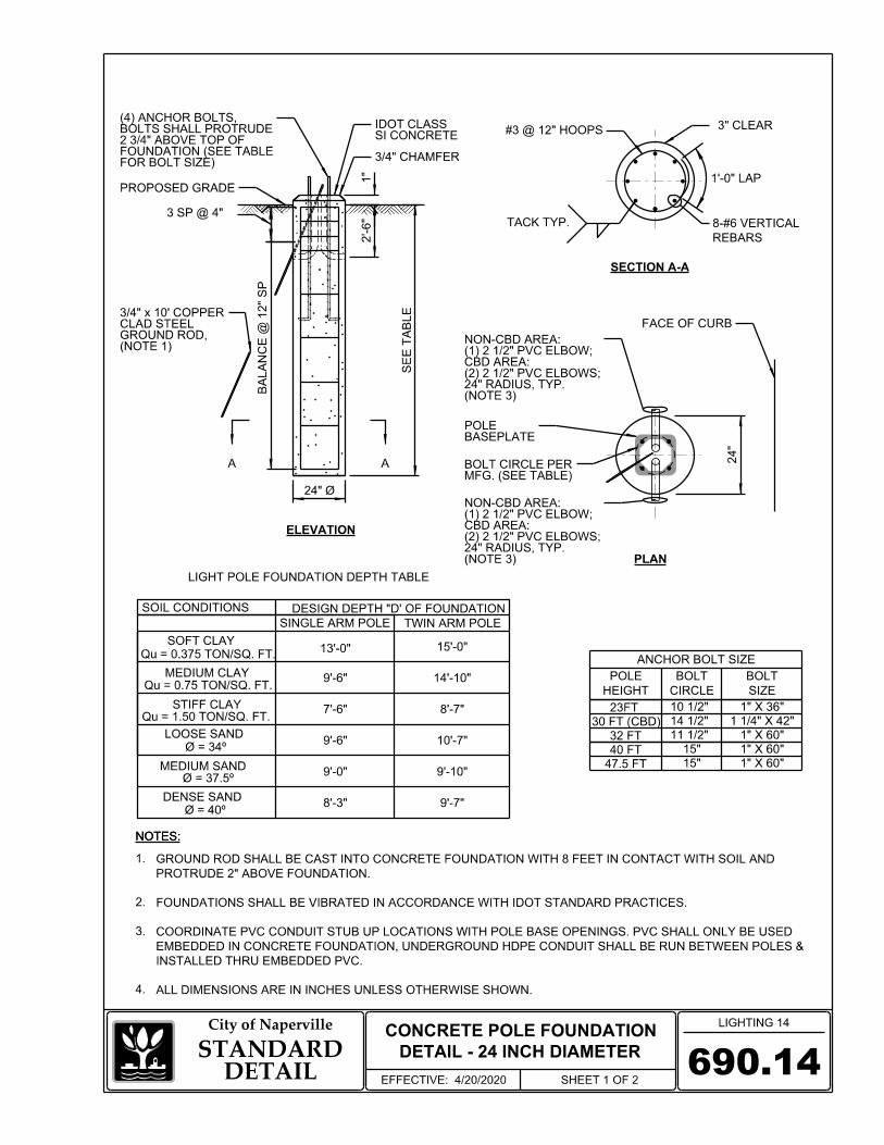
690.14
CONCRETE POLE FOUNDATION
DETAIL - 24 INCH DIAMETER
LIGHTING 14City of Naperville
STANDARDDETAIL
EFFECTIVE: 4/20/2020 SHEET 1 OF 2
ELEVATION
NOTES:
1.
3/4" CHAMFER
3 SP @ 4"
PROPOSED GRADE
BA
LA
NC
E @ 1
2" S
P
SE
E T
AB
LE
2'-6"
2.
3.
24" Ø
FOR BOLT SIZE)FOUNDATION (SEE TABLE 2 3/4" ABOVE TOP OF BOLTS SHALL PROTRUDE (4) ANCHOR BOLTS,
SOIL CONDITIONS DESIGN DEPTH "D' OF FOUNDATION
SOFT CLAY
MEDIUM CLAY
STIFF CLAY
LOOSE SAND
MEDIUM SAND
DENSE SAND
SINGLE ARM POLE TWIN ARM POLE
Qu = 0.375 TON/SQ. FT.
Qu = 0.75 TON/SQ. FT.
Qu = 1.50 TON/SQ. FT.
Ø = 34º
Ø = 40º
Ø = 37.5º
13'-0"
9'-6"
7'-6"
9'-6"
9'-0"
8'-3" 9'-7"
9'-10"
10'-7"
8'-7"
15'-0"
14'-10"
LIGHT POLE FOUNDATION DEPTH TABLE
A A
(NOTE 1)GROUND ROD, CLAD STEEL 3/4" x 10' COPPER
NOTES:
10 1/2"
14 1/2"
ANCHOR BOLT SIZE
32 FT 11 1/2"
40 FT
23FT
30 FT (CBD)
47.5 FT 15"
1" X 36"
1 1/4" X 42"
1" X 60"
1" X 60"
1" X 60"
15"
HEIGHT
POLE
CIRCLE
BOLT
SIZE
BOLT
SECTION A-A
3" CLEAR
1'-0" LAP
REBARS
8-#6 VERTICAL
#3 @ 12" HOOPS
TACK TYP.
SI CONCRETEIDOT CLASS
1"
ALL DIMENSIONS ARE IN INCHES UNLESS OTHERWISE SHOWN.
INSTALLED THRU EMBEDDED PVC.
EMBEDDED IN CONCRETE FOUNDATION, UNDERGROUND HDPE CONDUIT SHALL BE RUN BETWEEN POLES &
COORDINATE PVC CONDUIT STUB UP LOCATIONS WITH POLE BASE OPENINGS. PVC SHALL ONLY BE USED
FOUNDATIONS SHALL BE VIBRATED IN ACCORDANCE WITH IDOT STANDARD PRACTICES.
PROTRUDE 2" ABOVE FOUNDATION.
GROUND ROD SHALL BE CAST INTO CONCRETE FOUNDATION WITH 8 FEET IN CONTACT WITH SOIL AND
4.
PLAN
FACE OF CURB
24"
MFG. (SEE TABLE)BOLT CIRCLE PER
(NOTE 3)24" RADIUS, TYP.(2) 2 1/2" PVC ELBOWS; CBD AREA: (1) 2 1/2" PVC ELBOW; NON-CBD AREA:
(NOTE 3)24" RADIUS, TYP.(2) 2 1/2" PVC ELBOWS; CBD AREA: (1) 2 1/2" PVC ELBOW; NON-CBD AREA:
BASEPLATEPOLE

NOTES:
690.14
CONCRETE POLE FOUNDATION
DETAIL - 24 INCH DIAMETER
LIGHTING 14City of Naperville
STANDARDDETAIL
EFFECTIVE: 4/20/2020 SHEET 2 OF 2
5.
6.
7.
8.
9.
10.
11.
12.
13.
14.
15.
16.
NOTES:
THE RACEWAYS SHALL PROJECT 1 INCH ABOVE THE TOP OF THE FOUNDATION.
THE LIGHT POLE IS ERECTED.THE CABLE TRENCHES AND FOUNDATION SHALL BE BACK FILLED AND COMPACTED AS SPECIFIED BEFORE
ANCHOR BOLTS SHALL PROJECT 2 3/4" ABOVE THE TOP OF THE FOUNDATION.
THREADED ANCHOR ROD EMBEDDED IN THE FOUNDATION.THE ANCHOR BOLTS SHALL BE THREADED A MINIMUM OF 6 INCHES WITH A MINIMUM OF 3 INCHES OF
ACCORDING TO ASTM F1136.M298, CLASS 50 WITH A MAXIMUM COATING THICKNESS OF 150 UM (6 MILS) OR THE ELECTROLYTIC PROCESS PROCESS CONFORMING WITH AASHTO M232, THE MECHANICAL PLATING METHOD CONFORMING TO AASHTO ANCOR BOLTS, NUTS AND WASHERS SHALL BE COMPLETELY GALVANIZED BY EITHER THE HOT-DIPPED
ASTM F436.HEXAGON NUTS ACCORDING TO ASTM A1942H OR ASTM A563 DH, AND WASHERS SHALL BE ACCORDING TO THE ANCHOR BOLTS SHALL BE ACCORDING TO ASTM F1554 GRADE 725 (GRADE 105). NUTS SHALL BE
ENGINEER.THE ANCHOR BOLT. A TACK WELDED ANCHOR BOLT MAY BE SUBSTITUTED WITH THE APPROVAL OF THE ALLOWED. THE RADIUS OF THE HOOK BEND SHALL NOT BE LESS THAN 4 TIMES THE NOMINAL DIAMETER OF THE ANCHOR BOLT SHALL BE A HOOK ROD TYPE. COLD BENDING OF THE ANCHOR BOLT WILL NOT BE
STANDARD SPECIFICATION (MIN 7 DAYS) BEFORE LIGHT POLES ARE INSTALLED.THE CONCRETE SHALL BE CLASS SI. CONCRETE SHALL CURE ACCORDING TO ARTICLE 1020.13 OF IDOT
CHAMFERED 3/4".PRODUCE A UNIFORM SMOOTH SIDE TO THE TOP OF THE FOUNDATION. FOUNDATION TOP SHALL BE THE TOP OF THE FOUNDATION SHALL BE CONSTRUCTED LEVEL. A LINER OR FORM SHALL BE USED TO
BE WITHDRAWN AS THE CONCRETE IS DEPOSITED.THE FOUNDATION. IF SOIL CONDITIONS REQUIRE THE USE OF A LINER TO FORM THE HOLE, THE LINER SHALL THE HOLE FOR THE FOUNDATION SHALL BE MADE BY DRILLING WITH AN AUGER, OF THE SAME DIAMETER AS
FOUNDATION SHALL BE REPLACED.IF THE FOUNDATION HEIGHT, INCLUDING ANCHOR BOLTS, EXTENDS BEYOND THESE SPECIFIED LIMITS, THE CHORD ACROSS THE FOUNDATION, WITH ANCHOR BOLTS INCLUDED, IN ACCORDANCE AASHTO GUIDELINES. THE FOUNDATION SHALL NOT PROTRUDE MORE THAN 4 IN. ABOVE THE FINISHED GRADE WITHIN A 60 IN.
PLACED.THE ANCHOR BOLTS AND RACEWAYS SHALL BE PROPERLY SECURED IN PLACE BEFORE THE CONCRETE IS
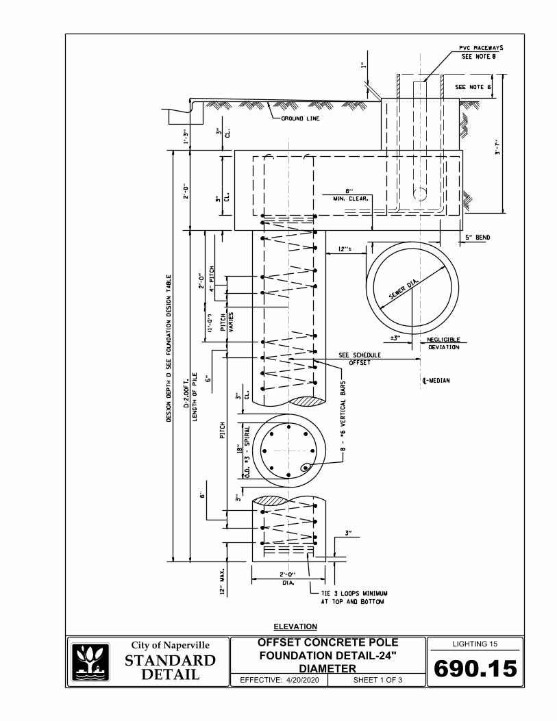
690.15
OFFSET CONCRETE POLE
FOUNDATION DETAIL-24"
DIAMETER
LIGHTING 15City of Naperville
STANDARDDETAIL
EFFECTIVE: 4/20/2020 SHEET 1 OF 3
ELEVATION
6
8
S
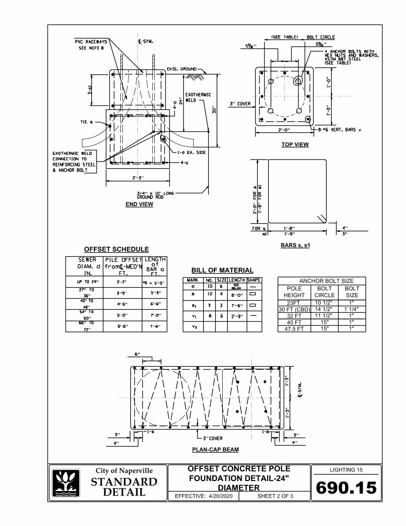
690.15STANDARD
DETAILEFFECTIVE: 4/20/2020 SHEET 2 OF 3
OFFSET CONCRETE POLE
FOUNDATION DETAIL-24"
DIAMETER
City of Naperville LIGHTING 15
PLAN-CAP BEAM
TOP VIEW
END VIEW
BARS s, s1
(SEE TABLE)ASTM 687 STEELHEX NUTS AND WASHERS. 4 ANCHOR BOLTS WITH
(SEE TABLE)
OFFSET SCHEDULE
BILL OF MATERIAL
10 1/2"
14 1/2"
ANCHOR BOLT SIZE
32 FT 11 1/2"
40 FT
23FT
30 FT (CBD)
47.5 FT 15"
15"
HEIGHT
POLE
CIRCLE
BOLT
SIZE
BOLT
1"
1 1/4"
1"
1"
1"
GROUND ROD3/4" x 10' LONG
8
S

NOTES:
690.15
LIGHTING 15City of Naperville
STANDARDDETAIL
EFFECTIVE: 4/20/2020 SHEET 3 OF 3
1.
NOTES:
2.
3.
4.
5.
6.
7.
OFFSET CONCRETE POLE
FOUNDATION DETAIL-24"
DIAMETER
8.
FOUNDATION DESIGN TABLE
SEE DETAIL 690.14 FOR SIZE AND NUMBER OF PVC RACEWAYS REQUIRED.
IS ERECTED.THE CABLE TRENCH SHALL BE BACKFILLED AND FIRMLY COMPACTED BEFORE THE LIGHT
RACEWAYS SHALL PROJECT 1" ABOVE THE TOP OF FOUNDATION.
FOUNDATION WITH THE BREAKAWAY DEVICE MANUFACTURER'S REQUIREMENTS.THE CONTRACTOR SHALL COORDINATE EXTENSION OF ANCHOR BOLTS ABOVE TOP OF
SHALL BE ACCORDING TO ASTM F 436.SHALL BE HEXAGON NUTS ACCORDING TO ASTM A 194 2H OR ASTM A 563 DH, AND WASHERS THE ANCHOR RODS SHALL BE ACCORDING TO ASTM F1554 GRADE 725 (GRADE105). NUTS
THE CONCRETE IS PLACED IN THE FORM. THE ANCHOR BOLTS AND RACEWAYS SHALL BE PROPERLY SECURED IN PLACE BEFORE
SUBSTITUTED WITH THE APPROVAL OF THE ENGINEER.NOMINAL DIAMETER OF THE ANCHOR ROD. A TACK WELDED ANCHOR ROD MAY BE NOT BE ALLOWED. THE RADIUS OF THE HOOK BEND SHALL NOT BE LESS THAN 4 TIMES THE THE ANCHOR ROD SHALL BE A HOOK ROD TYPE. COLD BENDING OF THE ANCHOR ROD WILL
EXCAVATION OF THE POLE FOUNDATION SHALL BE MADE WITH AN AUGER, 24" IN DIAMETER.

9"
(SEE TABLE) WIDTH
9 1/4"
BOLT CIRCLE (SEE TABLE)
(1) STRAP TO RETAIN DOOR
BOLT CIRCLE (SEE TABLE)
MATERIAL: ALUM. ALLOY 356-T6
MACHINE SCREWROUND HEAD TAMPERPROOF (1) FL" -20 x 1" LG. SS SOCKET
HOLE TAPPED1/2"-13NC
690.16TRANSFORMER BASE - 9 INCH
LIGHTING 16City of Naperville
STANDARDDETAIL
EFFECTIVE: 4/20/2020 SHEET 1 OF 1
BASE SUPPLIED WITH:
SIZE
HEIGHT
POLE
CIRCLE
TOP BOLT
CIRCLE
BOTTOM BOLT
DIA.
BOLT
23 FT
32 FT
40 FT
10 1/2"-12" 10"-12 3/4"
WIDTH
11 1/2"
10 1/2"-12"
11 1/2"-12"
14 1/2"-15"47.5 FT
10"-12 3/4"
10"-12 3/4"
14 1/2"-16 1/4" 15"
1"
1"
1"
1"
11 1/2"
11 1/2"
15" 1 1/4"14 1/2"-16 1/4"14 1/2"-15"30 FT (CBD)
8.
7.
6.
5.
4.
3.
2.
1.
SHIMS SHALL NOT BE ALLOWED.
OPTIMUM STATIC LOADS, USE THE LARGEST POSSIBLE BOLT CIRCLES.
FROM USERS MISAPPLICATION OR IMPROPER INSTALLATION. TO APPROACH
LOAD REQUIREMENTS AND INSTALLATION METHODS. FAILURES CAN RESULT
AUTHORIZED DISTRIBUTOR REGARDING USERS PROPOSED APPLICATION,
BEFORE INSTALLATION OF BREAKAWAY BASE, USER SHOULD CONSULT WITH
FHWA APPROVED MEETING AASHTO BREAKAWAY REQUIREMENTS
FOUR GALV. STL. FLAT WASHERS
FOUR GALV. STL. LOCK WASHERS
FOUR 8NC GALV. STL. HEX. NUTS
FOUR 8NC X 3 3/4" LONG GALV. STL. HEX. HD. BOLTS
EIGHT WASHERS 1/2" THICK X 2 3/4" O.D. (GALV. PER ASTM A153 OR ASTM B454)
DOOR AND 1/4"-20NC S.S. HEX. HD. SCREW
NOTES:NOTES:
1. COLOR TO MATCH POLE.

690.17
CAST IN PLACE CONCRETE
HANDHOLE DETAIL
LIGHTING 17City of Naperville
STANDARDDETAIL
EFFECTIVE: 4/20/2020 SHEET 1 OF 1
NOTES:
PLAN
ELEVATION
INCOVEREMBOSSED/CAST "STREET LIGHTING"
LIGHTINGSTREET
CONDUIT
FRAME PLAN28" SQUARE
CONDUIT BELLNONMETALLIC
4 FT SLACK
CONDUCTORGROUNDING EQUIPMENT
CONDUIT BELLNONMETALLIC
HANDHOLECONCRETE
SEE DETAIL "B" SEE DETAIL "A"
(TYP.)STEEL HOOKSGALVANIZED
(NOTE 2)SPLICE KIT DIRECT BURIAL U.L. LISTED
21 1/2"
8" MIN.
6"
18"
30"
CONDUCTORGROUNDING EQUIPMENT
4. NO SPLICING OF CURRENT CARRYING CONDUCTORS PERMITTED IN HANDHOLE.
GROUNDING CONDUCTOR.
3. BONDING/GROUNDING CONDUCTOR SHALL BE XLP-TYPE USE-600V & SIZED TO MATCH EQUIPMENT
2. EQUIPMENT GROUNDING CONDUCTOR SHALL NOT BE CUT.
1. FRAME AND COVER SHALL HAVE MINIMUM WEIGHT 140 LBS AND ABLE TO WITHSTAND AASHTO H-15 LOADING.
SOILUNDISTURBED
CA7FRENCH DRAIN
DETAIL "B"DETAIL "A"
HANDHOLE COVER HANDLE
FRAME WEBCAST CORNER
CAST ON TOP OF LIDW/ "STREET LIGHTING" HANDHOLE COVER
(NOTE 3)CONDUCTORGROUNDINGBONDING/
TERMINALCOMPRESSION HEAVY-DUTY
APPLIED TO THE ASSEMBLYCOMPOUND SHALL BE ANTI-CORROSION NUT, AND TWO WASHERS. STAINLESS STEEL BOLT,
FRAMEHANDHOLE
(NOTE 3)CONDUCTORGROUNDINGBONDING/
TERMINALCOMPRESSION HEAVY-DUTY

690.18
COMPOSITE CONCRETE
HANDHOLE DETAIL
LIGHTING 18City of Naperville
STANDARDDETAIL
EFFECTIVE: 4/20/2020 SHEET 1 OF 1
3.
2.
1.
NOTES:
2" ABOVE STONE BASEON PLANS TO EXTENDCONDUITS AS SHOWN
OPEN BOTTOM
W/ WASHER (2)STEEL HEX HEAD BOLT3/8-16 UNC STAINLESS
WITH GRADELID SHALL BE FLUSH
30"
MIN.
18"
NOTES:
ELEVATION
PLAN
LIGHTINGSTREET
("STREET LIGHTING")EMBOSSED LOGOBOLTED AND HAVE LID SHALL BE GASKETED,
HANDHOLEPOLYMER CONCRETE11" X 18" X 18" DEEP (MIN)
FOR DRAIN12" CA7 STONE
5.2.3 AND 5.2.4 OF WESTERN UNDERGROUND COMMITTEE GUIDE 3.6.
UNDERGROUND ENCLOSURE INTEGRITY", AND THE PROVISIONS OF PARAGRAPHS
ACCORDANCE WITH THE LATEST EDITION OF THE ANSI/SCTE 77 "SPECIFICATION FOR
BOX & LID SHALL MEET/EXCEED ANSI TIER 15 LOADING REQUIREMENTS, AND BE TESTED IN
POLYMER CONCRETE HANDHOLE AND LID SHALL BE GRAY.
NO SPLICING PERMITTED IN HANDHOLE.

GROUND LINE
FOUNDATION
ON REINFORCED CONCRETE
ARRANGED FOR MOUNTING
TRAFFIC BOX ENCLOSURE
BUSHING
SAND BASE
COMPACTED
MANUFACTURER
& EXPOSURE WITH CABINET
COORDINATE BOLT LOCATION
(4) 5/8"X24"X3" GALV. BOLTS
690.21
LIGHTING 21City of Naperville
STANDARDDETAIL
EFFECTIVE: 4/20/2020 SHEET 1 OF 3
SCHEMATIC-100A (NON-CBD)
STREET LIGHTING CONTROLLER
48"
50" 16.5"
FOUNDATION
CONCRETE
ENTRANCE OF MOISTURE
SEALED TO PREVENT
ENDS OF CONDUITS TO BE
SCREEN
VENT IN OVERHANG WITH
30"
EXISTS-24"x30"x5"
WHERE NO SIDEWALK
SIZE OF CONCRETE PAD
PADLOCKABLE
LOCK AND ALSO SHALL BE
CABINET SHALL HAVE CORBIN
CABINET DOOR
3/4" CHAMFER
NAPERVILLE
CITY OF
STREET LIGHTING
REPORT PROBLEMS
AT 630-420-6187 TO
PUBLIC WORKS
DEPART OF
CONTACT THE
SHALL BE VENTED.
AND SHIELD. CABINET
FINISH WITH SLOPED TOP
NATURAL ALUMINUM
NEMA 3R ENCLOSURE
ALUMINUM FABRICATED,
0.125 INCH TYPE 5052-H32
3.
2.
1.
NOTES:
NOTE 3
DOOR (NOTE 2)
PLATES ATTACHED TO
STAINLESS STEEL NAME
(2) 11" WIDE X 6" HIGH
NOTES:
FRONT VIEW SIDE VIEW
ROD
GROUND
3/4" x 10'
SIDEWALK
PVC RACEWAYS
(6) 2 1/2" SCH40
CONDUIT
2" RGS SERVICE
FOUNDATION PLAN
GROUND ROD
FOUNDATION
CONCRETE
FRONT
CABINET BASE
LIGHTING CONDUITS
RACEWAYS FOR
(6) 2 1/2" SCH40 PVC
CONDUIT
2 " RGS SERVICE
2"
1"
34"
20 1/2"
TOP ON OUTSIDE (SEE DETAIL 690.11).
ADHESIVE CONTROLLER ID LABEL LOCATED ON BACK OF CONTROLLER AT UPPER LEFT CORNER
"CONTACT THE DEPARTMENT OF PUBLIC WORKS AT 630-420-6187 TO REPORT PROBLEMS".
TOP NAMEPLATE LOGO "STREET LIGHTING CITY OF NAPERVILLE", AND BOTTOM NAMEPLATE LOGO
CONTRACTOR TO COORDINATE WITH CITY TO VERIFY IF METER IS REQUIRED.
30"
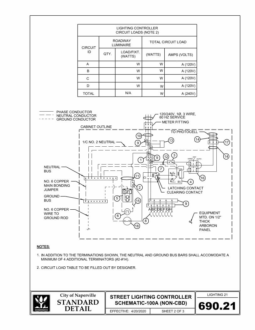
6
1/C NO. 2 NEUTRAL
TO PHOTOCELL
15
HAND
690.21
LIGHTING 21City of Naperville
STANDARDDETAIL
EFFECTIVE: 4/20/2020 SHEET 2 OF 3
A
B
C
D
TOTAL
AMPS (VOLTS)(WATTS)
GROUND CONDUCTOR
PHASE CONDUCTOR
NEUTRAL CONDUCTOR
A
(WATTS)
LOAD/FIXT.
TOTAL CIRCUIT LOAD
A (120V)
LUMINAIRE
ROADWAY
QTY.
N/A
W
W
W
W
A (120V)
A (120V)
A (120V)
A (240V)W
W
W
W
W
10
913
17
143129
1
7
9
8
2
11
LATCHING CONTACT
CLEARING CONTACT
PANEL
ARBORON
THICK
MTD. ON 1/2"
EQUIPMENT
CABINET OUTLINE
BC DEFG H
18
ID
CIRCUIT
METER FITTING
CIRCUIT LOADS (NOTE 2)
LIGHTING CONTROLLER
NOTES:
CIRCUIT LOAD TABLE TO BE FILLED OUT BY DESIGNER.
MINIMUM OF 4 ADDITIONAL TERMINATORS (#2-#14).
IN ADDITION TO THE TERMINATIONS SHOWN, THE NEUTRAL AND GROUND BUS BARS SHALL ACCOMODATE A
2.
1.
NOTES:
AUTO
SCHEMATIC-100A (NON-CBD)
STREET LIGHTING CONTROLLER
GFI
5
N.O.
N.C. R1
C
OC1 16
4
60 HZ SERVICE120/240V, 1Ø, 3 WIRE,
14
BUS
NEUTRAL
JUMPER
MAIN BONDING
NO. 6 COPPER
BUS
GROUND
GROUND ROD
WIRE TO
NO. 6 COPPER
OFF

690.21
LIGHTING 21City of Naperville
STANDARDDETAIL
EFFECTIVE: 4/20/2020 SHEET 3 OF 3
BREAKER
MAIN CIRCUIT
BREAKER
CONTROL CIRCUIT
PHOTOELECTRIC
CIRCUIT BREAKERS
BRANCH LINE
BLOCK
POWER DISTRIBUTION
AND BOX
RECEPTACLE
CABINET
CONTROL WIRE
PHOTOELECTRIC
CONTROL SWITCH
HAND-AUTO-OFF
APPR'D EQUAL
MFG./MODEL NO. OR
240V SERVICE RATING, 65KAIC
MOLDED CASE, PANEL -MOUNTED, 100 AMPERE, 2P,
120V RATING, 14KAIC
MOLDED CASE, PANEL-MOUNTED, 15 AMPERE, 1P,
120V RATING, 14KAIC
MOLDED CASE, PANEL -MOUNTED, 15 AMPERE, 1P,
BOX WITH WEATHERPROOF COVER
IN A WEATHERPROOF CAST ALUMINUM SINGLE GANG
COMMERCIAL GRADE GFCI 20A/120V, W.R., MOUNTED
100 AMPERE, 2P, 120V COIL, MECHANICALLY HELD
600 VOLT, INSULATED, SIZE AS REQ'D, 10KAIC
PLUNGER SWITCH
20A/120V, DOOR MOUNTED SNAP ACTION TYPE
20A, 3 POS. MTD IN CAST ALUM. ENCLOSURE
3 TERMINAL, SCREW TYPE, MAX. #10 WIRE SIZE
N/A
N/A
MARATHON
N/A
SQUARE D NO. SDSA 1175
N/A
SQUARE D NO. 9001 KYK 111
CINCH NO. 3-142
ITEM SPECIFICATION
2-600V XLP NO. 12
10 K AMPERE RATING
3-600V XLP NO. 10
2-600V XLP NO. 12
AUXILIARY RELAY
CABINET LIGHT
CONTACTOR
SERVICE CABLES
LAMPHOLDER WIRE
CONTROL WIRE
SURGE ARRESTOR
DOOR SWITCH
1
4
5
6
7
8
10 3-600V XLP NO. 2
2
3
11
12
13
14
15
16
17
18
9
RATING, 14KAIC
MOLDED CASE, PANEL -MOUNTED, (8), 30A, 1P, 120V
HONEYWELL NO. BA-2RQ1-A2
SQUARE D NO. 8903SQO10V02
HOFFMAN NO. DAH2001A
NTE NO. R28-11A10-120L
RAB NO. VXLED13NDG-3/4
EATON ED2100L 2P 100A
EATON EHD1015 1P 15A
EATON EHD1015 1P 15A
EATON EHD1030 1P 30A
LAMP/HEATER
CIRCUIT BREAKER
CONTACTS, ADJUSTABLE TIME DELAY
10A-120 V OPERATED DPDT 60 HZ COIL, 2 NO & 2 NC
FG-1DCV
B-5V, COVER: INTERMATIC NO.
GFRST20I, BOX: INTERMATIC NO.
RECEPTACLE: HUBBELL NO.
CABINET HEATER
SCHEMATIC-100A (NON-CBD)
STREET LIGHTING CONTROLLER
LED VAPORPROOF FIXTURE 16W 4000°K
TERMINAL BLOCK
PHOTOCELL
INTEGRAL THERMOSTAT (NOT ON EQUIPMENT PANEL)
200W-120V, FORCED FAN, FULLY ENCLOSED
NOTES:
POWER WIRING SHALL BE COPPER RHH/RHW 600 VOLTS.
ALL EXPOSED BUSBARS SHALL BE INSULATED.
WARNING AND PERSONNEL PROTECTION EQUIPMENT REQUIRED FOR SERVICING.
THE PANEL MANUFACTURER SHALL LABEL THE CABINET WITH THE APPROPRIATE ARC FLASH
ALL SWITCHES AND CONTROLS SHALL BE IDENTIFIED USING TWO COLOR ENGRAVED NAMEPLATES.
THE MAIN CIRCUIT BREAKER SHALL BE LABELED "SERVICE DISCONNECT."
"DOUBLE LUGGED."
CONNECTION OF SURGE ARRESTOR TO LINE SIDE OF MAIN CIRCUIT BREAKER SHALL NOT BE
AS AN "ENCLOSED INDUSTRIAL CONTROL PANEL" UNDER UL 508A.
THE LIGHTING CONTROLLER TOGETHER WITH ALL OF ITS COMPONENTS SHALL BE UL LISTED
7.
6.
5.
4.
3.
2.
1.
NOTES:
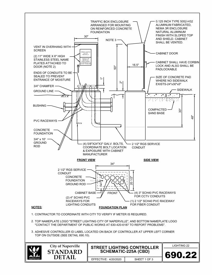
GROUND LINE
BUSHING
SAND BASE
COMPACTED
FOUNDATION
ON REINFORCED CONCRETE
ARRANGED FOR MOUNTING
TRAFFIC BOX ENCLOSURE
MANUFACTURER
& EXPOSURE WITH CABINET
COORDINATE BOLT LOCATION
(4) 5/8"X24"X3" GALV. BOLTS,
690.22
LIGHTING 22City of Naperville
STANDARDDETAIL
EFFECTIVE: 4/20/2020 SHEET 1 OF 3
48"
30"
50" 16.5"
FOUNDATION
CONCRETE
30"
3/4" CHAMFER
NAPERVILLE
CITY OF
STREET LIGHTING
REPORT PROBLEMS
AT 630-420-6187 TO
PUBLIC WORKS
DEPART OF
CONTACT THE
CONDUIT
2 1/2" RGS SERVICE
SCHEMATIC-225A (CBD)STREET LIGHTING CONTROLLER
ROD
GROUND
3/4" x 10'
SIDEWALK
CONDUIT
2 1/2" RGS SERVICE
GROUND ROD
FOUNDATION
CONCRETE
FRONT
CABINET BASE
34"
20 1/2"
2"
1"
PVC RACEWAYS
EXISTS-24"x30"x5"
WHERE NO SIDEWALK
SIZE OF CONCRETE PAD
SHALL BE VENTED.
AND SHIELD. CABINET
FINISH WITH SLOPED TOP
NATURAL ALUMINUM
NEMA 3R ENCLOSURE
ALUMINUM FABRICATED,
0.125 INCH TYPE 5052-H32
NOTE 3
ENTRANCE OF MOISTURE
SEALED TO PREVENT
ENDS OF CONDUITS TO BE
SCREEN
VENT IN OVERHANG WITH
3.
2.
1.
NOTES:NOTES:
TOP ON OUTSIDE (SEE DETAIL 690.10).
ADHESIVE CONTROLLER ID LABEL LOCATED ON BACK OF CONTROLLER AT UPPER LEFT CORNER
"CONTACT THE DEPARTMENT OF PUBLIC WORKS AT 630-420-6187 TO REPORT PROBLEMS".
TOP NAMEPLATE LOGO "STREET LIGHTING CITY OF NAPERVILLE", AND BOTTOM NAMEPLATE LOGO
CONTRACTOR TO COORDINATE WITH CITY TO VERIFY IF METER IS REQUIRED.
FOR CCTV CONDUITS
(4) 3" SCH40 PVC RACEWAYS
FOR FIBER CONDUIT
(1) 2 1/2" SCH40 PVC RACEWAY
FRONT VIEW SIDE VIEW
FOUNDATION PLANLIGHTING CONDUITS
RACEWAYS FOR
(2) 4" SCH40 PVC
PADLOCKABLE
LOCK AND ALSO SHALL BE
CABINET SHALL HAVE CORBIN
CABINET DOOR
DOOR (NOTE 2)
PLATES ATTACHED TO
STAINLESS STEEL NAME
(2) 11" WIDE X 6" HIGH
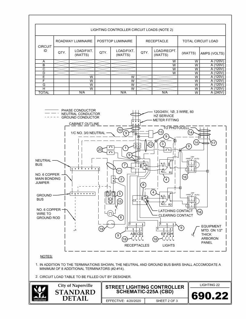
7
TO PHOTOCELL
12
16
3
HAND
HAND
18
9A B C D E F G H
14
18
PHASE CONDUCTOR
GROUND CONDUCTOR
NEUTRAL CONDUCTOR
CABINET OUTLINE
HZ SERVICE
120/240V, 1Ø, 3 WIRE, 60
N.O.
N.C. R1
C1
C
O
N.O.
N.C.
C
O
CLEARING CONTACT
C2
R2
LATCHING CONTACT
METER FITTING
BUS
NEUTRAL
JUMPER
MAIN BONDING
NO. 6 COPPER
AUTO
13 14
16
9
91
2
8
4
4
9
RECEPTACLES
20
17
AUTO
GROUND ROD
WIRE TO
NO. 6 COPPER
1/C NO. 3/0 NEUTRAL
6
11
9
LIGHTS
BUS
GROUND
910
OFF
OFF
LIGHTING 22City of Naperville
STANDARDDETAIL
EFFECTIVE: 4/20/2020 SHEET 2 OF 3
690.22
15
SCHEMATIC-225A (CBD)STREET LIGHTING CONTROLLER
NOTES:
CIRCUIT LOAD TABLE TO BE FILLED OUT BY DESIGNER.
MINIMUM OF 8 ADDITIONAL TERMINATORS (#2-#14).
IN ADDITION TO THE TERMINATIONS SHOWN, THE NEUTRAL AND GROUND BUS BARS SHALL ACCOMODATE A
2.
1.
A
AMPS (VOLTS)(WATTS)(WATTS)
LOAD/FIXT.
TOTAL CIRCUIT LOAD
A (120V)
QTY.
W
A (240V)
ID
CIRCUIT
ROADWAY LUMINAIRE
A (120V)WB
A (120V)WC
A (120V)WD
A (120V)WWE
A (120V)WWF
G W W A (120V)
H W W A (120V)
TOTAL W
QTY.
W
W
W
W
(WATTS)
LOAD/RECPT.
RECEPTACLE
(WATTS)
LOAD/FIXT.QTY.
POSTTOP LUMINAIRE
W
W
W
W
N/A
LIGHTING CONTROLLER CIRCUIT LOADS (NOTE 2)
N/AN/A
19
GFI 5
PANEL
ARBORON
THICK
MTD. ON 1/2"
EQUIPMENT

LIGHTING 22City of Naperville
STANDARDDETAIL
EFFECTIVE: 4/20/2020 SHEET 3 OF 3690.22
BREAKER
MAIN CIRCUIT
BREAKER
CONTROL CIRCUIT
PHOTOELECTRIC
AND BOX
RECEPTACLE
CABINET
CONTROL WIRE
PHOTOELECTRIC
240V SERVICE RATING, 65KAIC
MOLDED CASE, PANEL -MOUNTED, 225 AMPERE, 2P,
120V RATING, 14KAIC
MOLDED CASE, PANEL-MOUNTED, 15 AMPERE, 1P,
120V RATING, 14KAIC
MOLDED CASE, PANEL -MOUNTED, 15 AMPERE, 1P,
BOX WITH WEATHERPROOF COVER
IN A WEATHERPROOF CAST ALUMINUM SINGLE GANG
COMMERCIAL GRADE GFCI 20A/120V, W.R., MOUNTED
PLUNGER SWITCH
20A/120V, DOOR MOUNTED SNAP ACTION TYPE
20A, 3 POS. MTD IN CAST ALUM. ENCLOSURE
N/A
MARATHON
N/A
SQUARE D NO. SDSA 1175
N/A
SQUARE D NO. 9001 KYK 111
ITEM SPECIFICATION
10 K AMPERE RATING
3-600V XLP NO. 10
AUXILIARY RELAY
SURGE ARRESTOR
DOOR SWITCH
4
3-600V XLP #3/0
13
18
19
HONEYWELL NO. BA-2RQ1-A2
FG-1DCV
B-5V COVER: INTERMATIC NO.
GFRST20I BOX: INTERMATIC NO.
RECEPTACLE: HUBBELL NO.
SQUARE D NO. 8903SQO10V02
HOFFMAN NO. DAH2001A
NTE NO. R28-11A10-120L
RAB NO. VXLED13NDG-3/4
BLOCK
POWER DISTRIBUTION N/A
CIRCUIT BREAKERS
BRANCH LINE EATON EHD1030 1P 30A
EATON EHD1015 1P 15A
EATON EHD1015 1P 15A
EATON ED2225L 2P 225A
RATING, 14KAIC
MOLDED CASE, PANEL-MOUNTED, (8), 30A, 1P, 120V
20EATON EHD1020 1P 20A
RATING, 14 KAIC
MOLDED CAST, PANEL MOUNTED, (2) 20A-1P, 120V
SCHEMATIC-225A (CBD)STREET LIGHTING CONTROLLER
CONTACTS, ADJUSTABLE TIME DELAY 10A
120 V OPERATED DPDT 60 HZ COIL, 2 NO & 2 NC
INTEGRAL THERMOSTAT (NOT ON EQUIPMENT PANEL)
200W-120V, FORCED FAN, FULLY ENCLOSED
TERMINAL BLOCK
PHOTOCELL 17 3 TERMINAL, SCREW TYPE, MAX. #10 WIRE CINCH NO. 3-142
LAMP/HEATER
CIRCUIT BREAKER
CABINET HEATER
CONTROL SWITCH
HAND-AUTO-OFF
APPR'D EQUAL
MFG./MODEL NO. OR
100 AMPERE, 2P, 120V COIL, MECHANICALLY HELD
2-600V XLP NO. 12
2-600V XLP NO. 12
CABINET LIGHT
SERVICE CABLES
LAMPHOLDER WIRE
CONTROL WIRE
1
5
6
7
9
10
2
3
11
12
14
15
16
CONTACTOR #1
60 AMPERE, 2P, 120V COIL, MECHANICALLY HELD8 SQUARE D NO. 8903SPO10V02
600 VOLT, INSULATED, SIZE AS REQ'D, 10KAIC
BREAKERS
CCTV CIRCUIT
LED VAPORPROOF FIXTURE 16W 4000°K
CONTACTOR #2
NOTES:
POWER WIRING SHALL BE COPPER RHH/RHW 600 VOLTS.
ALL EXPOSED BUSBARS SHALL BE INSULATED.
WARNING AND PERSONNEL PROTECTION EQUIPMENT REQUIRED FOR SERVICING.
THE PANEL MANUFACTURER SHALL LABEL THE CABINET WITH THE APPROPRIATE ARC FLASH
ALL SWITCHES AND CONTROLS SHALL BE IDENTIFIED USING TWO COLOR ENGRAVED NAMEPLATES.
THE MAIN CIRCUIT BREAKER SHALL BE LABELED "SERVICE DISCONNECT."
"DOUBLE LUGGED."
CONNECTION OF SURGE ARRESTOR TO LINE SIDE OF MAIN CIRCUIT BREAKER SHALL NOT BE
AS AN "ENCLOSED INDUSTRIAL CONTROL PANEL" UNDER UL 508A.
THE LIGHTING CONTROLLER TOGETHER WITH ALL OF ITS COMPONENTS SHALL BE UL LISTED
7.
6.
5.
4.
3.
2.
1.
NOTES:

BLACK
RED
4/C #6 XLP/USE-21 1/4" HDPE WITH
690.23
TYPICAL STREET LIGHT
CONNECTION
LIGHTING 23City of Naperville
STANDARDDETAIL
EFFECTIVE: 4/20/2020 SHEET 1 OF 3
WHITE
GRN
GROUND ROD
BL
AC
K
WHIT
E
POLE WIRE 1/C #10 XLP/USE-2
FUSE KITS
BLACK CONDUCTORS.ALTERNATE BETWEEN RED AND POLES. FOR DAISY-CHAINED POLES CAP WITH SHRINK CAP FOR SINGLE FLUSH CUT RED CONDUCTOR AND
LUGGROUND POLE
DIRECT CONNECTED LIGHT POLE
NOTES:
1.
NOTES:
2.
NOTE 2
GREEN
SPLICE, TYP.WATERPROOF
ONLY)(CONCRETE FOUNDATION 3/4" X 10 FT GROUND ROD
COMEDCONNECTION BY DPU-E OR PEDESTAL FOR FUTURE COIL UP CABLES AT BASE OF
1/C #6 XLP/USE-2 BONDING JUMPER (GREEN).
AVAILABLE AND TO GROUND ROD IF AVAILABLE.CONNECT BONDING WIRE TO GROUNDING LUG IF WIRE. IF THESE CONDITIONS ARE ENCOUNTERED, OF DIRECT BURIED CONDUCTORS WITHOUT A GROUND EXISTING UNDERGROUND CONDUCTORS MAY CONSIST
OR COMEDPERFORMED BY NDPU-E INSIDE EQUIPMENT ARE TO BE POINT. ALL CONNECTIONS COMED SERVICE CONNECTION PUBLIC UTILITIES ELECTRIC OR NAPERVILLE DEPARTMENT OF
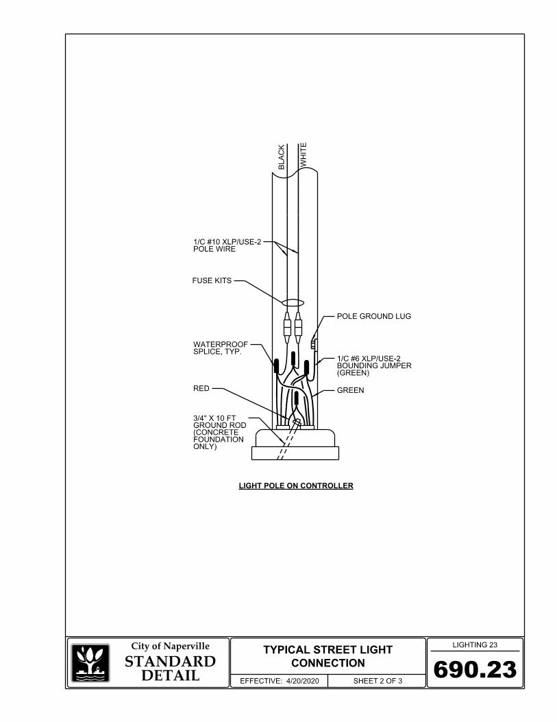
690.23
TYPICAL STREET LIGHT
CONNECTION
LIGHTING 23City of Naperville
STANDARDDETAIL
EFFECTIVE: 4/20/2020 SHEET 2 OF 3
LIGHT POLE ON CONTROLLER
SPLICE, TYP.WATERPROOF
ONLY)FOUNDATION (CONCRETE GROUND ROD 3/4" X 10 FT
GREENRED
POLE GROUND LUG
BL
AC
K
WHIT
E
POLE WIRE 1/C #10 XLP/USE-2
(GREEN)BOUNDING JUMPER1/C #6 XLP/USE-2
FUSE KITS

TRIMMED CABLES
DRAWINGS)NOTED ON CONTRACTCABLE (SIZE ASELECTRIC BRANCH
CRIMP TOOL USED)AND MFG. SUGGESTEDNUMBER OF CABLES(SIZED FOR ACTUALCOPPER SLEEVECOMPRESSION TYPE
EXPOSED SEALANT
CABLE TO LUMINAIRE#10 AWG ELECTRIC
690.23STANDARD
DETAILSHEET 3 OF 3
TYPICAL STREET LIGHT
CONNECTION
City of Naperville LIGHTING 23
LINE
LOAD#10 USE-2 XLP
#6 CU. STR. XLP USE 2
#10 USE-2 XLP
TYPICAL FUSE HOLDER CONNECTION IN POLE
NEUTRAL WIREWIRE AND MODEL #HET-AW-RLC-A FOR #HEB-AW-RLC-A-30A-600V FOR PHASE HOLDER BUSSMAN MODEL 30A SINGLE POLE BREAK AWAY FUSE
SPLICE DETAIL
NUMBER OF CABLES)ACCOMMODATE (SIZED TO WATERPROOF SEALANT, WITH FACTORY APPLIED HEAT-SHRINKABLE CAP
WIRES)AND IN BETWEENINSERT (AROUNDSEALANT TAPE OR
SEE SPLICING DETAIL
CONNECTION)(NEUTRAL "SLUG" FUSE CONNECTION) ANDMEM (UNGROUNDED FUSE TYPE MEQ OR 10A TIME DELAY
EFFECTIVE: 4/20/2020

690.24
LIGHTING 24City of Naperville
STANDARDDETAIL
EFFECTIVE: 4/20/2020 SHEET 1 OF 1
SERVICE CONNECTIONS
10' MAXIMUM
5' MINIMUM
ROD
3/4" GROUND
2" RGS
3/C #6 (B,W,R)
BUSHING
PROTECTIVE
30"
NDPU-E C50-3320
OR EQUAL, PER
MILBANK #NU8980-O-KK-100
2" RGS
4/C #6 (B,W,R,G)
ROD
3/4" GROUND
30"
5' MINIMUM
SERVICE CONNECTION TO TRAFFIC SIGNAL CONTROLLER
SERVICE CONNECTION TO STREET LIGHTING CONTROLLER
NOTES:
1.
2.
NOTES:
3/C #2 (B,W,R) IN 2" RGS FOR 100A CONTROLLER OR 3/C #3/0 (B,W,R) IN 2 1/2" RGS FOR 225A CONTROLLER.
CABLE TO GROUND ROD TO GREEN TERMINAL STRAP OF CONTROLLER.
INSTALL THREADED BUSHING WITH LUG ON RGS SERVICE CONDUIT: CONNECT BUSHING WITH 1/C #6 GREEN
CABINET (NOTE 1)
CONTROLLER
TRAFFIC SIGNAL
CABINET (NOTE 1)
CONTROLLER
STREET LIGHTING
NOTE 2
CONNECT
FOR DPU-E TO
COIL 8' OF CABLES
BY NDPU-E)
PEDESTAL (INSTALLED
NDPU-E SECONDARY
DPU-E TO CONNECT
COIL 8' OF CABLES FOR
BY NDPU-E)
PEDESTAL (INSTALLED
NDPU-E SECONDARY

690.30TYPICAL TRENCH DETAIL
LIGHTING 30City of Naperville
STANDARDDETAIL
EFFECTIVE: 4/20/2020 SHEET 1 OF 1
R.O.W. R.O.W.
___
1
2 2
3
4
12"
MIN 3
6"
MIN. 2'VARIABLEMIN. 2'
CENTERLINE OF TRENCH
RGS CONDUIT SLEEVE
TRENCH CROSS SECTION (NON-PAVED AREAS)
FINISHED GRADE
YELLOW WARNING TAPE 6" WIDE
SCH 40 HDPE CONDUIT30 " M
IN.
12" CENTERLINE OF TRENCH
BOTTOM OF CURB
YELLOW WARNING TAPE 6" WIDE
36 " M
IN.
12" MAXIMUM WIDTH
12" MAXIMUM WIDTH
TRENCH CROSS SECTION (UNDER ROADWAYS & COMMERCIAL DRIVEWAYS)
SLEEVERIGID GALVANIZED STEEL CONDUIT
5
SCH 40 HDPE CONDUIT
ROADWAY / PAVEMENT CROSSING
DRIVEWAYS UNLESS OTHERWISE APPROVED BY THE CITY.
5 CONDUIT SHALL BE PUSHED UNDER EXISTING ROADWAY AND COMMERCIAL
THE ENGINEER.
ACCORDANCE WITH THE SPECIAL PROVISIONS AND AS DIRECTED BY
4 CONTRACTOR SHALL PERFORM EXPLORATORY POTHOLES IN PAVEMENT IN
3 SLEEVE SHALL BE A MINIMUM OF 36" BELOW ROADWAY OR CURB BOTTOM.
2 SLEEVE SHALL EXTEND A MINIMUM OF 2 FT. BEYOND BACK OF CURB.
1 SLEEVE SHALL BE HEAVY WALL RIGID GALVANIZED STEEL (RGS) CONDUIT.