SECTION 600 MISCELLANEOUS CONSTRUCTION SECTION · PDF fileMISCELLANEOUS CONSTRUCTION SECTION...
76
601.02 381 SECTION 600 MISCELLANEOUS CONSTRUCTION SECTION 601 STRUCTURAL CONCRETE DESCRIPTION 601.01 This work consists of furnishing and placing portland cement concrete in accordance with these specifications and in conformity with the lines, grades and dimensions as shown on the plans or established. This work includes preparing concrete surfaces designated in the Contract and applying an approved colored Structural Concrete Coating to them. 601.02 Classification. The classes of concrete shown in Table 601-1 shall be used when specified in the Contract. Table 601-1 CONCRETE TABLE Cement Air Content: Water Concrete Required Field Content: Percent Cement Ratio: Class Compressive Strength Minimum or Range Maximum Range (Total) or Range B 3000 psi at 28 days 565 lbs./cu. yd. 5 – 8 N/A BZ 4000 psi at 28 days 610 lbs./cu. yd. N/A N/A D 4500 psi at 28 days 615 to 660 lbs./cu. yd. 5 – 8 0.44 DT 4500 psi at 28 days 700 lbs./cu. yd. 5 – 8 0.44 E 4200 psi at 28 days 660 lbs./cu. yd. 4 – 8 0.44 H 4500 psi at 56 days 580 to 640 lbs./cu. yd. 5 – 8 0.38 - 0.42 HT 4500 psi at 56 days 580 to 640 lbs./cu. yd. 5 – 8 0.38 - 0.42 P 4200 psi at 28 days 660 lbs./cu. yd. 4 – 8 0.44 S35 5000 psi at 28 days 615 to 720 lbs./cu. yd. 5 – 8 0.42 S40 5800 psi at 28 days 615 to 760 lbs./cu. yd. 5 – 8 0.40 S50 7250 psi at 28 days 615 to 800 lbs./cu. yd. 5 – 8 0.38 Class B concrete is an air entrained concrete for general use. Class D or H concrete may be substituted for Class B concrete. Additional requirements for Class B concrete are: Class B concrete shall have a nominal coarse aggregate size of 37.5 mm
Transcript of SECTION 600 MISCELLANEOUS CONSTRUCTION SECTION · PDF fileMISCELLANEOUS CONSTRUCTION SECTION...

601.02
381
SECTION 600MISCELLANEOUS CONSTRUCTION
SECTION 601STRUCTURAL CONCRETE
DESCRIPTION601.01 This work consists of furnishing and placing portland cement concrete inaccordance with these specifications and in conformity with the lines, grades anddimensions as shown on the plans or established.
This work includes preparing concrete surfaces designated in the Contract and applying anapproved colored Structural Concrete Coating to them.
601.02 Classification. The classes of concrete shown in Table 601-1 shall be usedwhen specified in the Contract.
Table 601-1 CONCRETE TABLE
Cement Air Content: Water Concrete Required Field Content: Percent Cement Ratio: Class Compressive Strength Minimum or Range Maximum
Range (Total) or Range B 3000 psi at 28 days 565 lbs./cu. yd. 5 – 8 N/A BZ 4000 psi at 28 days 610 lbs./cu. yd. N/A N/A D 4500 psi at 28 days 615 to 660
lbs./cu. yd. 5 – 8 0.44 DT 4500 psi at 28 days 700 lbs./cu. yd. 5 – 8 0.44 E 4200 psi at 28 days 660 lbs./cu. yd. 4 – 8 0.44 H 4500 psi at 56 days 580 to 640
lbs./cu. yd. 5 – 8 0.38 - 0.42 HT 4500 psi at 56 days 580 to 640
lbs./cu. yd. 5 – 8 0.38 - 0.42 P 4200 psi at 28 days 660 lbs./cu. yd. 4 – 8 0.44 S35 5000 psi at 28 days 615 to 720
lbs./cu. yd. 5 – 8 0.42 S40 5800 psi at 28 days 615 to 760
lbs./cu. yd. 5 – 8 0.40 S50 7250 psi at 28 days 615 to 800
lbs./cu. yd. 5 – 8 0.38
Class B concrete is an air entrained concrete for general use. Class D or H concretemay be substituted for Class B concrete. Additional requirements for Class Bconcrete are: Class B concrete shall have a nominal coarse aggregate size of 37.5 mm

382
601.02
(1½ inches) or smaller. Approved fly ash may be substituted for portland cement up to amaximum of 20 percent Class C or 30 percent Class F by weight.
Class BZ concrete is concrete for drilled piers. Additional requirements for classBZ concrete are: Entrained air is not required unless specified in the Contract. Highrange water reducers may be added at the job site to obtain desired slump andretardation. Slump shall be a minimum of 5 inches and a maximum of 8 inches).Class BZ caisson concrete shall be made with 19.0 mm (¾ inch) nominal sizedcoarse aggregate. Approved fly ash may be substituted for portland cement up to amaximum of 20 percent Class C or 30 percent Class F by weight.
Class D concrete is a dense medium strength structural concrete. Class H may besubstituted for Class D concrete. Additional requirements for Class D concrete are:An approved water reducing admixture shall be incorporated in the mix. Class Dconcrete shall be made with 19.0 mm (¾ inch) nominal sized coarse aggregate.When placed in a bridge deck, Class D concrete shall contain a minimum of 55percent AASHTO M 43 size No. 67 coarse aggregate. Approved fly ash may besubstituted for portland cement up to a maximum of 20 percent Class C or 30percent Class F by weight.
Class DT concrete may be used for deck resurfacing and repairs. Class HT may besubstituted for Class DT concrete. Additional requirements for Class DT concreteare: An approved water reducing admixture shall be incorporated in the mix. ClassDT concrete shall contain a minimum of 50 percent AASHTO M 43 size No. 7 orNo. 8 coarse aggregate. Approved fly ash may be substituted for portland cement upto a maximum of 20 percent Class C or 30 percent Class F by weight.
Class E concrete may be used for fast track pavements needing early strength inorder to open a pavement to service soon after placement. Additional requirementsfor Class E concrete are: Type III cement may be used. Class E concrete shallcontain a minimum of 55 percent AASHTO M 43 size No. 357 or No. 467 coarseaggregate. If all transverse joints are doweled, then Class E concrete shall contain aminimum of 55 percent AASHTO M 43 sizes No. 57, No. 67, No. 357, or No. 467coarse aggregate. In addition to the compressive strength requirements in Table 601-1 and unless stated otherwise on the plans, Class E concrete shall achieve a fieldcompressive strength of 2500 psi within 12 hours. Laboratory trial mix for Class Econcrete must produce an average 28 day flexural strength of at least 650 psi.Approved fly ash may be substituted for portland cement up to a maximum of 30percent Class F by weight.
Class H concrete is used for bare concrete bridge decks that will not receive awaterproofing membrane. Additional requirements for Class H concrete are: Anapproved water reducing admixture shall be incorporated in the mix. Class Hconcrete shall contain a minimum of 55 percent AASHTO M 43 size No. 67 coarseaggregate. Class H concrete shall contain cementitious materials in the followingranges: 450 to 500 pounds per cubic yard Type II portland cement, 90 to 125 pounds

383
601.02
per cubic yard flyash and 20 to 30 pounds per cubic yard silica fume. The totalcontent of Type II portland cement, flyash and silica fume shall be 580 to 640 poundsper cubic yard. Laboratory trial mix for Class H concrete must not exceedpermeability of 2000 coulombs at 56 days (ASTM C 1202). Laboratory trial mix forClass H concrete must not exhibit a crack at or before 14 days in the crackingtendency test (AASHTO PP 34).
Class HT concrete is used as the top layer for bare concrete bridge decks that willnot receive a waterproofing membrane. Additional requirements for Class HTconcrete are: An approved water reducing admixture shall be incorporated in themix. Class HT concrete shall contain a minimum of 50 percent AASHTO M 43 sizeNo. 7 or No. 8 coarse aggregate. Class HT concrete shall contain cementitiousmaterials in the following ranges: 450 to 500 pounds per cubic yard Type II portlandcement, 90 to 125 pounds per cubic yard flyash and 20 to 30 pounds per cubic yardsilica fume. The total content of Type II portland cement, flyash and silica fume shallbe 580 to 640 pounds per cubic yard. Laboratory trial mix for Class HT concretemust not exceed permeability of 2000 coulombs at 56 days (ASTM C 1202). Laboratorytrial mix for Class HT concrete must not exhibit a crack at or before 14 days in thecracking tendency test (AASHTO PP 34).
Class P concrete is used in pavements. Additional requirements for Class Pconcrete are: Class P concrete shall contain a minimum of 55 percent AASHTO M43 size No. 357 or No. 467 coarse aggregate. If all transverse joints are doweled,then Class P concrete shall contain a minimum of 55 percent AASHTO M 43 sizesNo. 57, No. 67, No. 357, or No. 467 coarse aggregate. Laboratory trial mix forClass P concrete must produce an average 28 day flexural strength of at least 650 psi.Class P concrete shall contain 70 percent to 80 percent portland cement and 20percent to 30 percent Class F fly ash in the total weight of cement plus fly ash.Unless acceptance is based on flexural strength, the total weight of cement plusClass F fly ash shall not be less than 660 pounds per cubic yard. If acceptance isbased on flexural strength, the total weight of cement plus Class F fly ash shall not beless than 520 pounds per cubic yard.
Class S35 concrete is a dense high strength structural concrete. Additionalrequirements for Class S35 concrete are: An approved water reducing admixtureshall be incorporated in the mix. Class S35 concrete shall be made with 19 mm(¾ inch) nominal sized coarse aggregate, i.e., 100 percent passing the 25.0 mm(1 inch) sieve and 90 percent to 100 percent passing the 19 mm (¾ inch) sieve.When placed in a bridge deck, Class S35 concrete shall contain a minimum of 55percent AASHTO M 43 size No. 67 coarse aggregate. Approved fly ash may besubstituted for portland cement up to a maximum of 20 percent Class C or 30percent Class F by weight.
Class S40 concrete is a dense high strength structural concrete. Additionalrequirements for Class S40 concrete are: An approved water reducing admixtureshall be incorporated in the mix. Class S40 concrete shall be made with 19 mm

384
601.02
(¾ inch) nominal sized coarse aggregate. When placed in a bridge deck, Class S40concrete shall contain a minimum of 55 percent AASHTO M 43 size No. 67 coarseaggregate. Approved fly ash may be substituted for portland cement up to amaximum of 20 percent Class C or 30 percent Class F by weight.
Class S50 concrete is a dense high strength structural concrete. Additionalrequirements for Class S50 concrete are: An approved water reducing admixtureshall be incorporated in the mix. Class S50 concrete shall be made with 19 mm(¾ inch) nominal sized coarse aggregate. When placed in a bridge deck, Class S50concrete shall contain a minimum of 55 percent AASHTO M 43 size No. 67 coarseaggregate. Approved fly ash may be substituted for portland cement up to amaximum of 20 percent Class C or 30 percent Class F by weight. Laboratory trialmix for Class S50 concrete must not exhibit a crack at or before 14 days in thecracking tendency test (AASHTO PP 34).
MATERIALS601.03 Materials shall meet the requirements specified in the following subsections:
Fine Aggregate 703.01Coarse Aggregate 703.02Portland Cement 701.01Fly Ash 701.02Water 712.01Air Entraining Admixture 711.02Chemical Admixtures 711.03Curing Materials 711.01Preformed Joint Material 705.01Reinforcing Steel 709.01Bearing Materials 705.06Epoxy 712.10Structural Concrete Coating 708.08
Type I or II cement shall be used unless high early strength concrete or sulfateresisting concrete is called for on the plans or as otherwise permitted.
Prestressing steel shall meet the requirements of subsection 714.01 except as notedon the plans.
Silica fume admixture shall conform to the requirements of subsection 701.03.
Calcium chloride shall not be used in any concrete unless otherwise specified.
601.04 (unused)

385
601.05
CONSTRUCTION REQUIREMENTS601.05 Proportioning. The Contractor shall submit a Concrete Mix Design Reportconsisting of design mix proportions, laboratory trial mix and aggregate data for eachclass of concrete being placed on the project. Concrete shall not be placed on theproject before the Concrete Mix Design Report has been reviewed and approved bythe Engineer. The Concrete Mix Design cannot be approved when the laboratory trialmix and aggregate data are the results from tests performed more than a year in thepast. The design mix proportions shall show the weights and sources of allingredients including cement, fly ash, aggregates, water, additives and the watercement ratio (w/c). When determining the w/c, cement (c) shall be the sum of theweight of the cement, the weight of the fly ash and the weight of silica fume.
The laboratory trial mix data shall include results of the following:
(1) AASHTO T 119 Slump of Hydraulic Cement Concrete.(2) AASHTO T 121 Weight per Cubic Foot, Yield, and Air Content (Gravimetric) of
Concrete. Air content from AASHTO T 152 Air Content of Freshly MixedConcrete by the Pressure Method may be used in lieu of the air content by thegravimetric method in AASHTO T 121.
(3) AASHTO T 22 Compressive Strength of Cylindrical Concrete Specimens shall beperformed with at least two specimens at 7 days and three specimens at 28 days.Three additional specimens tested at 56 days shall be required for Class H and HTconcrete.
(4) Class H and HT concrete shall include a measurement of permeability by ASTM C1202 Electrical Indication of Concrete’s Ability to Resist Chloride IonPenetration. The concrete test specimens shall be two 2 inch thick disks sawedfrom the centers of two molded 4 inch diameter cylinders cured no more than 56days in accordance with ASTM C 192 Standard Practice for Making and CuringConcrete Test Specimens in the Laboratory.
(5) Class H, HT and S50 concrete shall include a measurement of cracking byAASHTO PP 34 Standard Practice for Estimating the Cracking Tendency ofConcrete. The ring shall be cured in an indoor room with the temperaturemaintained 65°F to 75°F and relative humidity not exceeding 40 percent.
(6) Class E and P concrete shall include AASHTO T 97 Flexural Strength of Concrete(Using Simple Beam with Third-Point Loading) performed with two specimens atseven days and four specimens at 28 days.
(7) Class E concrete shall include a report of maturity relationships in accordancewith ASTM C 1074 with the following additions or modifications. TheContractor shall provide a multi-channel maturity meter and all necessary wireand connectors. The Contractor shall be responsible for the placement andmaintenance of the maturity meter and wire. Placement shall be as directed bythe Engineer.
(i) The cylinders used to establish the compressive strength vs. maturityrelationship shall be cast and cured in the field in conditions similar to theproject.

386
601.05
(ii) These cylinders shall be tested in pairs at times which yield compressivestrengths three sets of which are at or below 2500 psi and one of which isabove 2500 psi.
(iii) Testing to determine datum temperature or activation energy will not berequired.
(iv) A test slab shall be cast at the same time and location as the cylinders. Thetest slab shall have a length and width of 6 feet x 6 feet and a thickness equalto the pavement design thickness. The maturity of the test slab, when used inthe compressive strength vs. maturity relationship from the cylinders, shallindicate that a compressive strength of 2500 psi is achieved in the requiredtime. Slab maturity will be determined with two probes located in the slabapproximately 1 and 2 feet from the edge. The test slab shall be covered witha blanket similar to the one to be used on the pavement.
Except for class BZ concrete, the maximum slump of the delivered concrete shall be theslump of the approved concrete mix design plus 1½ inch. Except for class H and HTconcrete, the laboratory trial mix must produce an average 28 day compressive strength atleast 115 percent of the required 28 day field compressive strength. The laboratory trialmix for Class H or HT concrete must produce an average 56 day compressive strength atleast 115 percent of the required 56 day field compressive strength.
The laboratory trial mix shall have a relative yield of 0.99 to 1.02. When PortlandCement Concrete Pavement is paid with a volumetric pay quantity, the relative yield ofthe concrete produced on the project shall be 0.99 to 1.02. If the relative yield of theproduced concrete does not conform to this range for two consecutive yielddeterminations, concrete production shall cease and the Contractor shall present aplan to correct the relative yield to the Engineer.
Aggregate data shall include the results of the following:
(1) AASHTO T 11 Materials Finer Than 75 um (No. 200) Sieve in MineralAggregates by Washing.
(2) AASHTO T 19 Unit Weight and Voids in Aggregate.(3) AASHTO T 21 Organic Impurities in Fine Aggregate for Concrete.(4) AASHTO T 27 Sieve Analysis of Fine and Coarse Aggregates.(5) AASHTO T 84 Specific Gravity and Absorption of Fine Aggregate.(6) AASHTO T 85 Specific Gravity and Absorption of Coarse Aggregate.(7) AASHTO T 96 Resistance to Degradation of Small-Size Coarse Aggregate by
Abrasion and Impact in the Los Angeles Machine.(8) AASHTO T 104 Soundness of Aggregate by Use of Sodium Sulfate or
Magnesium Sulfate.(9) AASHTO T 176 Plastic Fines in Graded Aggregates and Soils by use of the
Sand Equivalent Test(10) ASTM C 535 Resistance to Degradation of Large-Size Coarse Aggregate by
Abrasion and Impact in the Los Angeles Machine(11) ASTM C 1260 Potential Alkali Reactivity of Aggregates (Mortar-Bar Method)

601.06
387
Any aggregate with an expansion of 0.10 percent or more at 16 days after casting asdetermined by ASTM C 1260 shall not be used unless mitigative measures areincluded in the mix design and subsequent results of CPL 4202 with the design mixproportions show an expansion not exceeding 0.10 percent at 16 days after casting.The Concrete Mix Design Report shall state what mitigative measures were includedin the concrete mix design and include results for ASTM C 1260 and CPL 4202.
The Concrete Mix Design Report shall include Certified Test Reports showing thatthe cement, flyash and silica fume admixture meet the specification requirements andsupporting this statement with actual test results. The certification for silica fumeshall state the solids content if the silica fume admixture is furnished as slurry.
Where the Contractor’s use of fly ash results in any delay, necessary change inadmixture quantities or source, or unsatisfactory work, the cost of such delays,changes or corrective actions shall be borne by the Contractor.
The Contractor shall submit a new Concrete Mix Design Report meeting the aboverequirements when a change occurs in the source, type, or proportions of cement, flyash, or aggregate. Unless otherwise permitted by the Engineer, the product of onlyone type of portland cement from one mill of any one brand shall be used in aconcrete mix design.
Review and approval of the Concrete Mix Design by the Engineer does not constituteacceptance of the concrete. Acceptance will be based solely on the test results ofconcrete placed on the project.
601.06 Batching. Measuring and batching of materials shall be done at a batchingplant in accordance with AASHTO M 157.
The Contractor shall furnish a batch ticket (delivery ticket) with each load for allclasses of concrete. Concrete delivered without a batch ticket containing completeinformation as specified shall be rejected. The Contractor shall collect and completethe batch ticket at the placement site and deliver all batch tickets to the Engineer on adaily basis. The Engineer shall have access to the batch tickets at any time during theplacement. The following information shall be provided on each batch ticket:
(1) Supplier’s name and date(2) Truck number(3) Project number and location(4) Concrete class designation and item number(5) Cubic yards batched(6) Time batched(7) CDOT mix design number(8) Type, brand, and amount of each admixture(9) Type, brand, and amount of cement and fly ash(10) Weights of fine and coarse aggregates

388
601.06
(11) Moisture of fine and coarse aggregate(12) Gallons of batch water (including ice)
The Contractor shall add the following information to the batch ticket at theplacement site:
(13) Gallons of water added by truck operator plus quantity of concrete in thetruck each time water is added
(14) Number of revolutions of drum at mixing speed (for truck mixed concrete)(15) Discharge time(16) Location of batch in placement(17) Water cement ratio (required for deck concrete only)
The drum on each truck mixer shall be reversed prior to charging to eliminate anywash water remaining in the mixer.
(a) Portland Cement and Fly Ash. Either sacked or bulk cement may be used. Nofraction of a sack of cement shall be used in a batch of concrete unless thecement is weighed.
All bulk cement shall be weighed on an approved weighing device. The bulkcement weighing hopper shall be sealed and vented to preclude dusting duringoperation. The discharge chute shall be so arranged that cement will not lodge init or leak from it.
Separate storage and handling equipment shall be provided for the fly ash. The flyash may be weighed in the cement hopper and discharged with the cement.
(b) Water. Unless water is to be weighed, the water-measuring equipment shallinclude an auxiliary tank from which the measuring tank shall be filled. Themeasuring tank shall be equipped with an outside tap and valve to provide forchecking the calibration unless other means are provided for readily andaccurately determining the amount of water in the tank. The volume of theauxiliary tank shall be at least equal to that of the measuring tank. In lieu of thevolume method specified above, the Contractor will be permitted to use a watermetering device that is accurate within the prescribed limits.
(c) Aggregates. Aggregates from different sources and of different gradings shallnot be stockpiled together.
Aggregate shall be handled from stockpiles or other sources to the batching plantin such manner as to secure a uniform grading of the material. Aggregates thathave become segregated, or mixed with earth or foreign material, shall not beused. All aggregates produced or handled by hydraulic methods, and washedaggregates, shall be stockpiled or binned for draining at least 12 hours beforebeing batched. Rail shipment requiring more than 12 hours will be accepted asadequate binning only if the car bodies permit free drainage. In case the
389
601.07
aggregates contain high or non-uniform moisture content, storage or stockpileperiod in excess of 12 hours may be required.
(d) Bins and Scales. The batching plant may include bins, weighing hoppers, andscales for the fine aggregate and for each size of coarse aggregate. If cement isused in bulk, a bin, hopper, and scale for cement shall be included. A singleweighing hopper with an accumulative scale will be permitted, provided a separatescale is used for weighing cement.
Scales shall meet the requirements of subsection 109.01.
601.07 Mixing. Concrete may be mixed in stationary mixers, in a central-mix plant,in truck mixers, or in self-contained mobile mixers. Mixing time shall be measuredfrom the time all materials, except water, are in the drum.
Silica fume, when specified, shall be added to the mix during initial batching.
(a) Mixing General. The concrete shall be deposited in place within 90 minutesafter batching when concrete is delivered in truck mixers or agitating trucks, andwithin 60 minutes when delivered in non agitating trucks.
The 90 minute time limit for mixer or agitating trucks may be extended to 120minutes if:(1) No water is added after 90 minutes.(2) The concrete temperature prior to placement is less than 90 F
The 90 minute time limit for mixer or agitating trucks may be extended to 180minutes if:(1) No water is added after 90 minutes.(2) The concrete temperature prior to placement is less than 90 F.(3) The approved concrete mix contains a water reducing and retarding admixture
which conforms to AASHTO M 194, Type D.
(b) Stationary Mixing. When mixed in a central mixing plant, the mixing time shallbe between 50 and 90 seconds. Four seconds shall be added to the specifiedmixing time if timing starts the instant the skip reaches its maximum raisedposition. Mixing time ends when the discharge chute opens. Transfer time inmultiple drum mixers is included in mixing time. The contents of an individualmixer drum shall be removed before a succeeding batch is emptied therein.
The volume of concrete mixed per batch may exceed the mixer’s nominalcapacity, as shown on the manufacturer’s standard rating plate on the mixer, up to10 per cent provided concrete test data for strength, segregation, and uniformconsistency are satisfactory, and provided spillage of concrete does not occur.
The batch shall be so charged into the drum that a portion of the mixing watershall enter in advance of the cement and aggregates. The flow of water shall be

390
601.07
uniform and all water shall be in the drum by the end of the first 15 seconds ofthe mixing period. The throat of the drum shall be kept free of suchaccumulations as may restrict the free flow of materials into the drum.
The timing device on stationary mixers shall be equipped with a bell or othersuitable warning device adjusted to give a clearly audible signal each time thelock is released. In case of failure of the timing device, the Contractor will bepermitted to operate while it is being repaired, provided the Contractor furnishesan approved timepiece equipped with minute and second hands. If the timingdevice is not placed in good working order within 24 hours, further use of themixer will be prohibited until repairs are made.
(c) Truck Mixing. Truck mixed concrete shall conform with one of the following:
1. Concrete mixed entirely in a truck mixer equipped with a mechanical countershall be partially mixed at the plant or in transit for not less than 20revolutions of the drum at mixing speed. The revolutions of the drum atcharging speed shall not be counted as mixing revolutions. The concrete shallbe mixed between 50 and 100 revolutions of the mixer drum at mixing speedat the delivery site before discharge of the concrete.
2. Concrete partially mixed in a stationary central mixing plant with mixing broughtto completion in a truck mixer (known as shrink mixing) shall be mixed for aminimum of 30 seconds in the stationary mixer. Mixing shall be completed in thetruck mixer for at least 20 but not more than 100 revolutions of the mixer drumat mixing speed at the delivery site before discharge of the concrete.
3. Concrete mixed entirely in a stationary mixer and delivered to the job in atruck mixer shall be remixed for a minimum of 20 revolutions of the mixingdrum at mixing speed at the job site prior to discharge.
When water is added at the delivery site to control the consistency of theconcrete as specified in subsection 601.02, the concrete shall be mixed forat least 20 revolutions of the mixer drum at mixing speed for each additionof water before discharge. These revolutions are in addition to the minimumrevolutions required for mixing at the delivery site. The added water shall notcause the water/cement ratio to exceed the requirements in subsection601.02. Water from all sources shall be documented by the ready mixproducer on the delivery slip for each load of concrete.
The Contractor shall provide a Concrete Truck Mixer Certification. Thiscertification shall show the various pick-up and throw-over configurationsand wear marks so that the wear on the blades can be checked. Blades shall bereplaced when any part or section is worn 1 inch or more below the originalheight of the manufacturer’s design. A copy of the manufacturer’s design,showing the dimensions and arrangement of blades, shall be available to theEngineer at all times.

391
601.09
The Contractor shall furnish a water-measuring device in good workingcondition, mounted on each transit mix truck, for measuring the water addedto the mix after the truck has left the charging plant. Each measuring deviceshall be equipped with an easy-to-read gauge. Water shall be measured to theaccuracy prescribed in AASHTO M 157.
(d) Self Contained Mobile Mixer. Proportioning and mixing equipment shall be ofthe self-contained, mobile, continuous mixing type subject to the following:
The mixer shall be self-propelled and be capable of carrying sufficient unmixeddry, bulk cement, fine aggregate, coarse aggregate, admixtures and water toproduce on the site not less than 6 cubic yards of concrete. The mixer shall haveone bin for each size aggregate.
The mixer shall be capable of positive measurement of cement being introducedinto the mix. A recording meter visible at all times and equipped with a ticketprintout shall indicate the quantity of total concrete mix.
The mixer shall provide positive control of the flow of water into the mixingchamber. Water flow shall be indicated by flow meter and be readily adjustable toprovide for minor variations in the aggregate moisture.
The mixer shall be capable of being calibrated to automatically proportion andblend all components of indicated composition on a continuous or intermittentbasis as required by the finishing operation, and shall discharge mixed materialthrough a conventional chute directly in front of the finishing machine.
The Contractor shall perform calibration tests according to the equipmentmanufacturer’s recommendations at the beginning of each project, and when thereis a change in the mix design proportions or source of materials. The Engineermay require a calibration test or yield check whenever a change in thecharacteristics of the mixture is observed. The tolerances in proportioning thevarious ingredients shall be according to subsection 6.8 of AASHTO M 241.
601.08 Air Content Adjustment. When a batch of concrete delivered to the projectdoes not conform to the minimum specified air content, an airentraining admixtureconforming to subsection 711.02 may be added, one time only for the batch, at theContractor’s option prior to consideration for rejection or price adjustment. Afterthe admixture is added the concrete shall be re-mixed for a minimum of 20revolutions of the mixer drum at mixing speed. The concrete will then be re-testedand if found acceptable may be placed in accordance with the specifications. Amaximum of three batches per day may be adjusted by adding air entraining admixtureat the delivery site.
601.09 Forms.

392
601.09
(a) Design. Forms shall be mortar tight and sufficiently rigid to prevent distortiondue to the pressure of the concrete and other loads incidental to the concreteoperations, including vibration.
The rate of depositing concrete in forms shall be controlled to preventdeflections of the form panels in excess of the deflections permitted by thesespecifications.
Forms for exposed concrete surfaces shall be designed and constructed so thatthe formed surface of the concrete does not undulate excessively in any directionbetween studs, joists, form stiffeners, form fasteners, or wales. Undulationsexceeding 3/32 inch between the center to center distance of studs, joists, formstiffeners, form fasteners or wales will be considered to be excessive. Should anyform or forming system, even though previously approved for use, produce aconcrete surface with excessive undulations, its use shall be discontinued untilmodifications satisfactory to the Engineer have been made. Portions of concretestructures with surface undulations in excess of the limits herein may be rejectedby the Engineer.
Forms for drainage inlets may be constructed of any suitable material that willproduce a structure with the inside dimensions and at least the wall thicknessesshown on the plans. Undulations of finished interior wall surfaces shall notexceed 0.5 inch.
Where called for in the Contract, the Contractor shall design and construct apermanent bridge deck forming system. Based on what is indicated, theContractor will be permitted one of the following sets of options:
(1) If the plans indicate that permanent deck forms are optional, the Contractorshall have the option of constructing a cast-in-place bridge deck usingconventional forms, a full depth cast-in-place bridge deck using permanentsteel bridge deck forms, or a partial depth cast-in-place bridge deck usingprecast panel deck forms as a portion thereof.
(2) If the plans indicate that permanent deck forms are required, the Contractorshall have the option of constructing a full depth cast-in-place bridge deckusing permanent steel bridge deck forms, or a partial depth cast-in-placebridge deck using precast panel deck forms as a portion thereof.
(3) If the plans indicate that precast panel deck forms are required, theContractor shall construct a partial depth cast-in-place bridge deck usingprecast panel deck forms as a portion thereof.
(b) Construction. Forms shall be constructed and maintained so as to prevent theopening of joints due to shrinkage of the lumber. The use of ties consisting oftwisted wire loops to hold forms in position will not be permitted. Deck slab

393
601.09
forms between girders shall be constructed with no allowance for settlementrelative to the girders.
The inside surfaces of forms shall be cleaned of all dirt, mortar and foreign material.Forms which will later be removed shall be thoroughly coated with form oil prior touse. The form oil shall be a commercial quality form oil or other equivalent coatingwhich will permit the ready release of the forms and will not discolor the concrete.
Concrete shall not be deposited in the forms until all work connected withconstructing the forms has been completed; all materials required to be embedded inthe concrete have been placed, unless otherwise specified on the plans or approved;and the Engineer has inspected said forms and material. Such work shall include theremoval of all dirt, chips, sawdust, water and other foreign material from the forms.
Anchor devices may be cast into the concrete for later use in supporting forms orfor lifting precast members. The use of driven types of anchorages for fasteningforms or form supports to concrete will not be permitted.
Backforms may be omitted with the approval of the Engineer in cases involvingfootings which can be placed in the dry without the use of cribs or coffer dams. Insuch cases, the entire excavation shall be filled with concrete to the requiredelevation of the top of the footing. The additional concrete required shall beplaced at the expense of the Contractor, except when footings are poured out torock. Extra concrete required to pour footings out to rock will be allowed in theconcrete quantities, provided that no allowance will be made for any concreteextending more than 6 inches in any direction beyond the neat lines of thefootings as shown on the plans.
(c) Form Lumber. Form lumber for all exposed concrete surfaces shall be dressed atleast on one side and two edges and shall be constructed so as to produce mortar-tight joints and smooth, even concrete surfaces. Forms shall be filleted andchamfered as shown on the plans, and shall be given a bevel or draft in the case ofall projections, such as girders and copings, to assure easy removal.
Unless otherwise specified, forms for exposed surfaces shall be constructed withtriangular fillets ¾ inch by ¾ inch at all exterior corners.
(d) Metal Ties. Metal ties or anchorages within the forms shall be so constructed asto permit their removal to a depth of at least ½ inch from the face without injuryto the concrete. When wire ties are used the wires shall be cut back at least ¼inch from the face of the concrete upon removal of the forms. The cavities shallbe filled with cement mortar and the surface left sound, smooth, even anduniform in color.
(e) Walls. Where the bottom of the forms is inaccessible, the lower form boardsshall be left loose or other provisions made so that extraneous material may beremoved from the forms immediately before placing the concrete.
394
601.09
(f) Surface Treatment. All forms shall be treated with oil prior to placing reinforcementexcept that an approved nonpetroleum base form release agent shall be used forsurfaces which are to receive Class 5, Masonry Coating Finish. Wood forms shall bethoroughly moistened with water immediately before placing the concrete.
For rail members or other members with exposed faces, the forms shall betreated with an approved form release agent to prevent the adherence of concrete.Material which will adhere to or discolor the concrete shall not be used.
All concrete forms for surfaces to which Structural Concrete Coating is to be appliedshall be treated with a water based concrete form release agent prior to placingreinforcement.
(g) Metal Forms for General Use. The specifications for forms, regarding design,mortar tightness, filleted corners, beveled projections, bracing, alignment,removal, reuse and oiling, apply to metal forms. The metal used for forms shallbe of such thickness that the forms will remain true to shape. All bolt and rivetheads shall be countersunk. Clamps, pins or other connecting devices shall bedesigned to hold the forms rigidly together and to allow removal without injury tothe concrete. Metal forms which do not present a smooth surface or do not lineup properly shall not be used. Metal forms shall be free from rust, grease or otherforeign matter. Permanent steel bridge deck forms shall be as described insubsection 601.10.
(h) Removal of Forms. The forms for any portion of the structure shall not beremoved until the concrete is strong enough to withstand damage when the formsare removed.
Unless controlled by beam or cylinder tests, the following minimum periods oftimes, exclusive of days when the ambient temperature is below 40 F, may beused as a guide for removal of forms and supports.
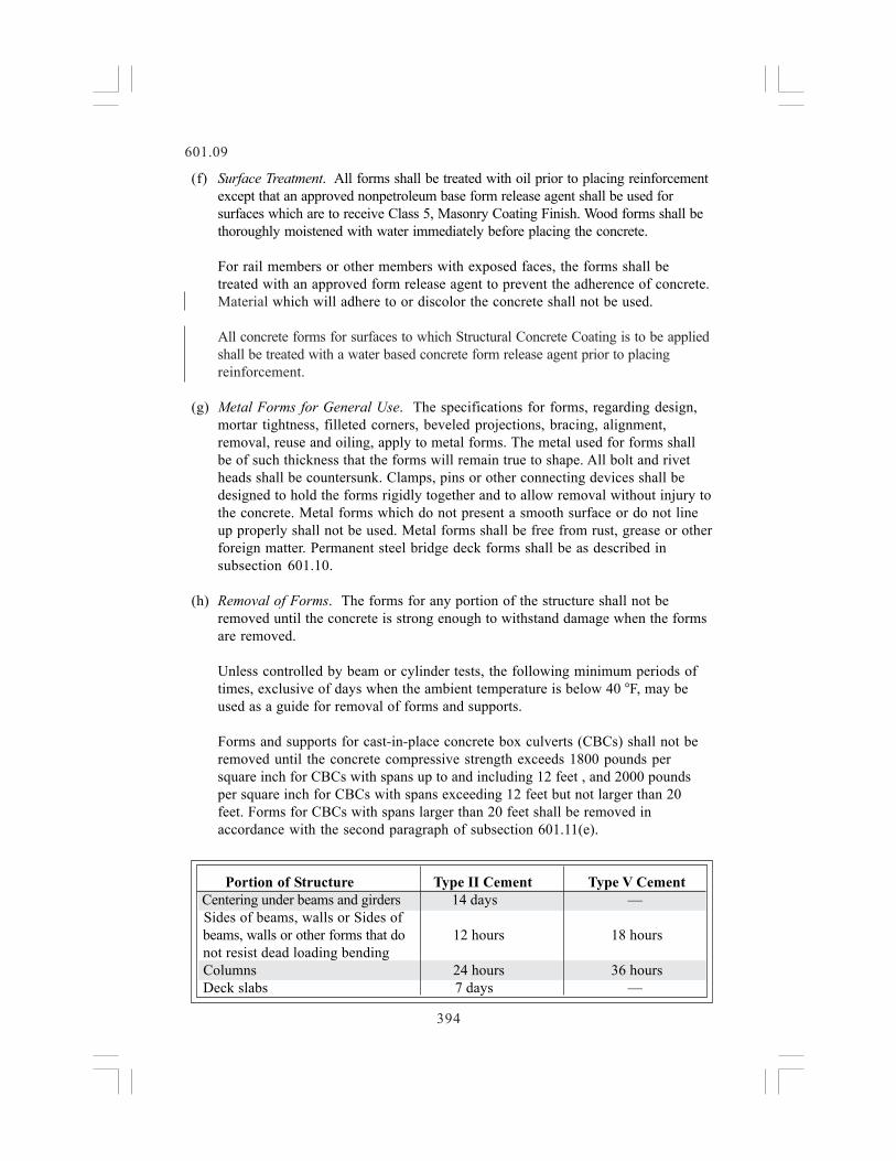
Forms and supports for cast-in-place concrete box culverts (CBCs) shall not beremoved until the concrete compressive strength exceeds 1800 pounds persquare inch for CBCs with spans up to and including 12 feet , and 2000 poundsper square inch for CBCs with spans exceeding 12 feet but not larger than 20feet. Forms for CBCs with spans larger than 20 feet shall be removed inaccordance with the second paragraph of subsection 601.11(e).
Portion of Structure Type II Cement Type V Cement Centering under beams and girders 14 days — Sides of beams, walls or Sides of beams, walls or other forms that do 12 hours 18 hours not resist dead loading bending Columns 24 hours 36 hours Deck slabs 7 days —

395
601.09
When field operations are controlled by beam or cylinder tests, the removal offorms, supports and housing, and the discontinuance of heating and curing maybegin when the concrete is found to have the required compressive strength.
If high-early-strength (Type III) cement or accelerating admixtures are used, theabove periods may be reduced as approved.
Forms for median barrier, railing or curbs, may be removed at the convenience ofthe Contractor after the concrete has hardened.
All forms shall be removed except permanent steel bridge deck forms and formsused to support hollow abutments or hollow piers when no permanent access isavailable into the cells. When permanent access is provided into box girders, allinterior forms and loose material shall be removed, and the inside of box girdersshall be cleaned with an industrial vacuum.
(i) Patching. The mixed formula for patch mortar shall be determined by trial toobtain a good color match with the concrete when both patch and concrete arecured and dry.
(j) Re-use of Forms. The shape, strength, rigidity, watertightness and surfacesmoothness of reused forms shall be maintained at all times. Warped or bulgedlumber shall not be used.
(k) Precast Panel Deck Forms. Working drawings for precast panel deck forms shallbe submitted to the Engineer in conformity with subsection 105.02.
Prestressing for precast panel deck forms shall be in accordance with subsection618.07(a).
Concrete for precast panel deck forms shall be cured in accordance withsubsection 618.12.
Precast panel deck forms shall be stored and transported in a horizontal positionand shall conform to the requirements of subsections 618.14(c) and 618.15.
When precast panels are erected, the fit of mating surfaces shall have no morethan a 1/8 inch gap to prevent concrete leakage. If such fit cannot be provided, thejoint shall be filled with grout or sealed with an acceptable caulking compoundprior to the placing of the cast-in-place portion of the slab.
Precast panels and their accessories, including components to set grade, shall notbe attached by welding to steel girders or other structural steel elements orreinforcing steel. Welding, including arc strikes or grounding on any structuralsteel element is prohibited. The Engineer will inspect all girder flanges forblemishes from arc strikes. All identified blemishes shall be repaired in

601.09
396
accordance with AWS D1.5 Section 3.10. Repair of all blemishes shall be at theContractor’s expense.
Support angles or other steel components that will be left in place and exposed tothe atmosphere in the final product shall be galvanized in accordance withsubsection 509.11.
601.10 Permanent Steel Bridge Deck Forms.(a) General. Permanent steel bridge deck forms for concrete deck slab may be used
as an alternate to removable forms pursuant to this specification and whenspecified on the plans. Permanent steel bridge deck forms shall not be used in thecantilever portions of the deck slab.
(b) Materials. Permanent steel bridge deck forms and supports shall be fabricatedfrom steel conforming to ASTM A 653 (Grades A through E) having a galvanizedcoating designation of Z600 (G 165) according to ASTM A 653.
(c) Design. The following criteria shall govern the design of permanent steel bridgedeck forms:
1. The steel forms shall be designed on the basis of dead load of form,reinforcement and plastic concrete plus 50 pounds per square foot forconstruction loads. The unit working stress in the steel sheet shall be notmore than 0.725 of the specified minimum yield strength of the materialfurnished, but not to exceed 36,000 pounds per square inch.
If permanent steel bridge deck forms are used, the depth of slab shown on theplans shall be provided above the forms. The weight of additional concrete tofill form flutes and the steel form dead load shall not exceed a total of fivepounds per square foot from edge to edge of flanges in each bay and fromfront face to front face of abutments.
2. Deflection under the mass of the forms, the plastic concrete andreinforcement shall not exceed 1/180 of the form span or ½ inch whicheveris less, but in no case shall the design loading be less than 120 psf total.
The permissible form camber shall be based on the actual dead loadcondition. Camber shall not be used to compensate for deflection in excessof the foregoing limits.
3. The design span of the form sheets shall be the clear span of the form plus 2inches measured parallel to the form flutes.
4. Physical design properties shall be computed in accordance withrequirements of the American Iron and Steel Institute Specification for theDesign of Cold Formed Steel Structural Members, latest published edition.

397
601.10
5. All reinforcing steel shall have a minimum concrete cover of 1 inch.
6. Permanent steel bridge deck form shall not be used in panels wherelongitudinal deck construction joints are located between stringers.
7. Permanent steel bridge deck forms and their accessories shall not beattached by welding’ to steel girders or other structural steel bridge elementsor reinforcing steel. Welding, including arc strikes or grounding, on anystructural steel element is prohibited. Blemishes, when found, shall beremoved in accordance with AWS D1.5 Section 3.10. Determination that ablemish exists will be made by the Engineer and the repair shall be at theContractor’s expense.
8. The Contractor shall submit two sets of the fabricator’s shop and erectiondrawings to the Engineer. The drawings shall be designed and sealed by theContractor’s Engineer. The drawings will not be approved or returned to theContractor. The drawings shall indicate the grade of steel, the physical andsection properties of all permanent steel bridge deck form sheets, andattachment details.
(d) Construction. All forms shall be installed in accordance with fabrication anderection plans submitted to the Engineer in accordance with subsection601.10(c)8.
Form sheets shall not be permitted to rest directly on the top of the girderflanges. Sheets shall be securely fastened to form supports and shall have aminimum bearing length of 1 inch at each end. Form supports shall be placed indirect contact with the girder flange. All attachments shall be made by bolts, clipsor other approved means. Welding will not be permitted to flanges.
Permanently exposed form metal where the galvanized coating has been damagedshall be thoroughly cleaned, wire brushed and painted with two coats of zincoxide-zinc dust primer, Federal Specification TT-P-641d, Type II, no color added,to the satisfaction of the Engineer. Minor heat discoloration in areas of weldsneed not be touched up.
Transverse construction joints shall be located at the bottom of a flute and ¼ inchweep holes shall be field drilled at not more than 12 inches on center along theline of the joint.
(e) Placing of Concrete. Concrete shall be placed with proper vibration of theconcrete to avoid honeycomb and voids, especially at construction joints,expansion joints, valleys, and ends of form sheets. Placement sequences,procedures and mixes shall be approved by the Engineer. Calcium chloride or anyother admixture containing chloride salts shall not be used in the concrete placedon permanent steel bridge deck forms.

398
601.10
(f) Inspection. If the Engineer determines that the procedures used during theplacement of the concrete warrant inspection of the under-side of the deck, theContractor shall remove at least one section of the forms at a location and timeselected by the Engineer for each span. This will be done as soon after placing theconcrete as practicable in order to provide visual evidence that the concrete mixand the Contractor’s procedures are obtaining the desired results. An additionalsection shall be removed if the Engineer determines that there has been anychange in the concrete mix or in the Contractor’s procedures warrantingadditional inspection.
After the deck concrete has been in place for a minimum period of two days, theconcrete shall be tested for soundness and bonding of the forms by sounding witha hammer as directed. If areas of doubtful soundness are disclosed by thisprocedure, the Contractor shall remove the forms from such areas as ordered, forvisual inspection. If corrective action is not required, the cost of form removalwill be borne by the Department. If corrective action is required, the cost of formremoval and corrective action shall be borne by the Contractor.
The Contractor shall provide inspection platforms or other approved means ofstationary support from which the above visual inspection can be made.
601.11 Falsework.(a) General. Falsework is defined as any temporary construction used to support
vertical loads for a structure until it becomes self-supporting. Formwork is thetemporary structure or mold used to retain plastic or fluid concrete in itsdesignated shape until it hardens.
The Contractor shall be responsible for designing and constructing falseworkwhich provides the necessary rigidity, supports the loads imposed, and producesin the finished structure the lines and grades indicated on the plans.
The Contractor shall have a Professional Engineer determine whether falseworkdrawings are or are not necessary. When falsework drawings are determined to beunnecessary, the Contractor shall submit a written statement signed by theContractor’s Professional Engineer so stating. All falsework drawings, includingrevisions, prepared by the Contractor’s Professional Engineer shall meet therequirements of subsection 601.11 and shall be provided by the Contractor to theEngineer for record purposes only. The drawings shall be approved by, and containthe seal and signature of, a Professional Engineer registered in the State ofColorado. These drawings shall be approved and signed by the Contractor prior toproviding them to the Engineer. The drawings will not be approved by theEngineer.
(b) Certification. Prior to placement of any concrete supported by falsework, theContractor’s Engineer shall certify that falsework materials and construction havebeen inspected and that all falsework design, materials, and construction conformto the requirements of the Contract and are safe for the placement of concrete. A

399
601.11
copy of the certification on an acceptable form shall be submitted to the Engineerfor record purposes.
(c) Falsework Design.
1. The falsework design drawings shall show the stresses and deflections in allload supporting members, and anticipated total settlement of falseworkfootings and joint take-up. Anticipated settlements shall not exceed 1 inch.The maximum deflection used in the design of the falsework shall be 1/270of clear span, irrespective of the fact that the deflection may be compensatedfor by camber strips.
2. The design of falsework shall be based on the use of loads and conditionswhich are no less severe than those described in this section. The stresseslisted are based upon the use of undamaged, high quality materials and suchstresses shall be reduced by the Contractor if lesser quality materials are tobe used. The Contractor is responsible for the proper evaluation of thefalsework materials and design of the falsework to safely carry the actualloads imposed.
3. The design load for falsework shall consist of the sum of dead and livevertical loads and an assumed horizontal load.
A. Dead loads shall include the weight of concrete, reinforcing steel,forms, and falsework. The weight of concrete and reinforcing steel shallbe assumed to be at least 150 pounds per cubic foot for normal concreteand at least 120 pounds per cubic foot for lightweight concrete.
B. Timber dead load is 50 pounds per cubic foot. The dead load of timberforms may be assumed at 10 pounds per square foot for memberssmaller than 6 inch x 6 inch. Dead load for steel and steel forms shall be490 pounds per cubic foot. The weight of any other forming materialsshall be specified on the drawings.
C. Live loads shall consist of the actual weight of any equipment to besupported by falsework applied as concentrated loads at the points ofcontact and a uniform load of not less than 50 pounds per square footapplied over the area supported.
4. The assumed horizontal load to be resisted by the falsework bracing systemshall be the sum of the actual horizontal loads due to equipment, constructionsequence or other causes and an allowance for wind; however, the assumedhorizontal load to be resisted in any direction shall not be less than 2 percentof the total dead load for falsework up to 30 feet high, and four percent forfalsework over 30 feet high. The falsework shall be designed so that it willhave sufficient rigidity to resist the horizontal load prior to the placement ofconcrete.

400
601.11
5. The entire bridge superstructure cross-section, except railing, shall beconsidered to be placed at one time except as provided herein. Girder stemsand connected bottom slabs, if placed more than five days prior to the topslab, may be considered to be self supporting between falsework posts at thetime the top slab is placed, provided that the distance between falseworkposts does not exceed four times the depth of the portion of the girderplaced in the first pour.
6. Falsework footings shall be designed to carry the load imposed upon themwithout exceeding the estimated soil bearing values and anticipatedsettlements.
7. Foundations for individual towers where the maximum leg load exceeds 30kips shall be designed and constructed to provide uniform settlement underall legs of each tower under all loading conditions.
8. If the concrete is to be post-tensioned in the field, the falsework shall bedesigned to support all increased or readjusted loads caused by theprestressing forces, as shown on the plans.
9. The falsework design drawings shall include the following minimuminformation:
(1) Type and grade of structural materials.(2) Allowable material stresses in bending, compression, and shear.(3) Modulus of elasticity, “E”.(4) Stress factors if used for short term duration loading (timber only).(5) Summary of critical tower leg loads and locations on falsework
drawings.(6) Weight of deck finishing machine and wheel or support spacing.(7) References for load data used for standardized falsework components.(8) Specification references for design criteria.(9) The bearing value of the soil as determined by the Contractor when
footing type foundations are to be used.
10. Falsework design shall be based on the current edition of one of thefollowing applicable specifications. However, it shall be based on AASHTOSpecifications if highway traffic is to be supported.
AASHTO American Association of State Highway and TransportationOfficials, Standard Specifications for Highway Bridges.
AISC American Institute of Steel Construction, Manual of SteelConstruction.
ACI American Concrete Institute, Formwork for Concrete SP4Building Code Requirements for Reinforced Concrete.

401
601.11
NFPA National Forest Products Association, National DesignSpecifications for Stress Grade Lumber.
AITC American Institute of Timber Construction Manual.
11. Manufactured Assemblies. Loading of jacks, brackets, columns, joists and othermanufactured devices shall not exceed the manufacturer’s recommendations or40 percent of the ultimate load carrying capacity of the assembly based on themanufacturer’s tests or additional tests as necessary. The maximum allowabledead load deflection of joists shall be limited to 1/500 of their spans.
The Contractor shall furnish catalog or equivalent data showing themanufacturer’s recommendations or perform tests, as necessary, todemonstrate the adequacy of any manufactured device proposed for use. TheContractor shall not substitute other manufacturer’s components unless themanufacturer’s data encompasses such substitutions or field tests affirm theintegrity of the system.
12. Connection details shall be so designed that structural shoring members aresecure for all loading conditions.
(d) Falsework Construction. The falsework shall be constructed in accordance withthe falsework drawings. Suitable jacks, wedges, or camber strips shall be used toset the forms to the required grade or camber and to take up any settlement in theformwork either before or during the placing of concrete. Supports for deck slabforms shall be constructed so as to prevent settlement relative to the girders. Theamount of camber to be used to represent the behavior of the permanent structureis shown on the plans.
Falsework shall be constructed so that any concentrated loads applied to steelgirder webs shall be applied within 6 inches of a flange or stiffener. Where loadsare applied to steel girder webs, they shall be applied in a manner that will notproduce distortion to the web.
Temporary struts and ties shall be provided as necessary to resist lateral loadsapplied to the girders and to prevent appreciable relative movement between theedge of deck forms and the adjacent steel girder. Where the deck overhangexceeds 1/3 of the distance between the girders, the exterior girder shall be bracedto prevent rotation due to the weight of the overhang support falsework andconcrete placement operation.
The Contractor shall provide tell-tales attached to the forms and readable fromthe ground, in enough systematically placed locations, to determine the totalsettlement of the entire portion of the structure where concrete is being placed.
Should unanticipated events occur, including settlements that deviate more than± 3/8 inch from those indicated on the falsework drawings, which in the opinion of

402
601.11
the Engineer would prevent obtaining a structure conforming to the requirementsof these specifications, the placing of concrete shall be discontinued until thecorrective measures satisfactory to the Engineer are provided. In the eventsatisfactory measures are not provided prior to initial setting of the concrete inthe affected area, the placing of concrete shall be discontinued at a locationdeter-mined by the Engineer. All unacceptable concrete shall be removed.
(e) Falsework Removal. Falsework supporting any span of a simple span bridge shallnot be released until after the last concrete, excluding concrete above the bridgedeck, has attained the compressive strength of at least 80 percent of the required28 day strength, 0.80f c but in no instance prior to five days after the placementof the concrete.
Falsework supporting any span of a continuous or rigid frame bridge shall not bereleased until after the last concrete, excluding concrete above the bridge deck,has been placed in all spans and has attained the compressive strength of at least80 percent of the required 28 day strength, 0.80f c but in no instance prior tofive days after placement of the concrete.
Falsework for arch bridges shall be removed uniformly and gradually, beginning atthe crown, to permit the arch to take its load slowly and evenly.
Falsework supporting overhangs and deck slabs between girders shall not bereleased before five days after the deck concrete has been placed.
Falsework for pier caps which will support steel or precast concrete girders shallnot be released before five days after the cap concrete has been placed unless thecompressive strength of at least 80 percent of the required 28 day strength,0.80f c is obtained. Girders shall not be erected onto such pier caps until theconcrete in the cap has attained the compressive strength of at least 80 percent ofthe required 28 day strength, 0.80f c shown on the plans.
If authorized, test hammer results may be used in lieu of test cylinders for formremoval determinations only. The test hammer must be calibrated against similarconcrete of known strength from the same aggregate source prior to use.
Falsework for cast-in-place prestressed portions of structures shall not bereleased until after the pre-stressing steel has been tensioned.
601.12 Placing Concrete.(a) General. A preplacement conference shall be held with selected Contractor and
Department personnel prior to placement of concrete bridge decks to discuss themethod and sequence of placing concrete.
At the pre-placement conference, the Contractor shall present a concrete winterprotection plan for acceptance by the Engineer. The accepted concrete winterprotection plan shall contain information on the number and type of heat sources

601.12
403
to be used, a sketch detailing the enclosure materials, and all other pertinentinformation. Sufficient equipment shall be supplied to continuously maintain thespecified temperature uniformly in all parts of the enclosure. Insulated blanketson top of the bridge deck and freely circulated artificial heat below the deck willbe permitted.
Concrete shall not be placed until forms have been completed and materialsrequired to be embedded in the concrete have been placed, and the Engineer hasinspected the forms and materials. The forms shall be cleaned of all debris beforeconcrete is placed.
The external surface of all concrete shall be thoroughly worked during the placing bymeans of tools of an approved type. The working shall be such as to force all coarseaggregate from the surface and to bring mortar against the forms to produce a smoothfinish substantially free from water and air pockets, or honeycomb.
(b) Hot Weather Limitations. Placing of concrete during hot weather shall belimited by the temperature of the concrete at the time of placing. Mixed concretewhich has a temperature of 90 F or higher, shall not be placed.
The Contractor shall provide fogging equipment and keep the concrete surfacemoist at all times by fogging with an approved atomizing nozzle until the curingmaterial is in place.
The aggregate stockpiles shall be kept moist at all times.
(c) Cold Weather Limitations. The mixed concrete temperature shall be between 50 and90 F at the time of placement. Water, aggregates, or both shall be heated whennecessary under such control and in sufficient quantities to avoid fluctuations in thetemperature of the concrete of more than 10 F from batch to batch.
To avoid the possibility of flash set when the water is heated to a temperature inexcess of 100 F, the water and the aggregates shall be charged into the mixerbefore the cement is added.
Heating equipment or methods which alter or prevent the entrainment of therequired amount of air in the concrete shall not be used. The equipment shall becapable of heating the materials uniformly. Aggregates and water used for mixingshall not be heated to a temperature exceeding 150 F. Materials containing frostor lumps of frozen material shall not be used.
Stockpiled aggregates may be heated by the use of dry heat or steam. Aggregatesshall not be heated directly by gas or oil flame or on sheet metal over fire.
When aggregates are heated in bins, steam-coil or water-coil heating, or othermethods which will not be detrimental to the aggregates may be used. The use oflive steam on or through binned aggregates will not be permitted.

601.12
404
Concrete shall not be placed on frozen ground. Before concrete placement, allice, snow, and frost shall be completely removed from within formwork. Saltshall not be used to thaw ice, snow, or frost.
(d) Chutes and Troughs. Concrete shall be placed so as to avoid segregation of thematerials and the displacement of the reinforcement.
Concrete shall not be dropped more than 5 feet, unless confined by closed chutesor pipes. Care shall be taken to fill each part of the form by depositing theconcrete as near final position as possible. The coarse aggregate shall be workedback from the forms and worked around the reinforcement without displacing thebars. After initial set of the concrete, the forms shall not be jarred and strain shallnot be placed on the ends of projecting reinforcement.
Where steep slopes are required, the chutes shall be equipped with baffle boardsor be in short lengths that reverse the direction of movement.
Concrete shall not be pumped through aluminum alloy pipe.
All chutes, troughs and pipes shall be kept clean and free from coatings ofhardened concrete.
(e) Vibrating. Unless otherwise directed, the concrete shall be consolidated withsuitable mechanical vibrators operating within the concrete. When required,vibrating shall be supplemented by hand spading with suitable tools to assureproper and adequate consolidation.
Vibrators shall be of a type and design approved by the Engineer. They shall becapable of frequencies of at least 10,000 vibrations per minute, in air.
Vibrators shall be so manipulated as to work the concrete thoroughly around thereinforcement and imbedded fixtures and into corners and angles of the forms.Vibrators shall not be used as a means to cause concrete to flow or run intoposition in lieu of placing. The vibration at any point shall be of sufficientduration to accomplish consolidation, but shall not be prolonged to the pointwhere segregation occurs.
(f) Depositing Concrete Under Water. Concrete, except for cofferdam seals, shallnot be deposited under water, unless approved by the Engineer. If approved, careshall be exercised to prevent the formation of laitance. Concrete shall not bedeposited until all laitance, which may have formed on concrete previouslyplaced, has been removed. Pumping shall be discontinued while depositingfoundation concrete if it results in a flow of water inside the forms. If concrete,except for cofferdam seals, is deposited under water, the proportion of cementused shall be increased at least 25 percent at the Contractor’s expense. Concretedeposited under water shall be carefully placed in a compact mass in its finalposition by means of a tremie. The discharge or bottom end of the tremie shall be

601.12
405
lowered to contact the foundation at the start of the concrete placement and shallbe raised during the placement at a rate which will insure that the bottom ordischarge end of the tremie is continuously embedded or buried in fresh concretea minimum of 12 inches. Air and water shall be excluded from the tremie pipe bykeeping the pipe continuously filled. The continuity of the placement operationshall be maintained without breaking the seal between the concrete mass and thedischarge end of the tremie until the lift is completed. The concrete placementshall not be disturbed after it has been deposited.
(g) Placement. Concrete shall be placed in horizontal layers not more than 18 inchesthick except as hereinafter provided. When less than a complete layer is placed in oneoperation, it shall be terminated in a vertical bulkhead. Each layer shall be placed andconsolidated before the preceding batch has taken initial set. Each layer shall be soconsolidated as to avoid the formation of a con-struction joint with a preceding layerwhich has not taken initial set. Bridge deck concrete on superelevation or grade thatexceeds 2 percent, shall be placed from the low point upward.
When the placing of concrete is temporarily discontinued, the concrete, afterbecoming firm enough to retain its form, shall be cleaned of laitance and otherobjectionable material to a sufficient depth to expose sound concrete. The topsurfaces of concrete adjacent to the forms shall be smoothed with a trowel tominimize visible joints upon exposed faces. Work shall not be halted within 18inches of the top of any face, unless provision has been made for a coping lessthan 18 inches thick, in which case the construction joint may be made at theunder side of the coping.
Immediately after the work of placing concrete is halted, all accumulations ofmortar splashed upon the reinforcement and surfaces of forms shall be removedbefore the concrete takes its initial set. Care shall be taken when cleaningreinforcing steel to prevent damage to or breakage of the concrete-steel bond.
Where Class DT concrete is used for patching, repair, or topping of existingconcrete, the area that the Concrete Class DT contacts shall be prepared byshotblasting 1/8 to 3/16 inch deep or rotomilling. If Class DT concrete is notplaced within one week of the shotblasting or rotomilling the area shall then besandblasted and cleaned of all sand, concrete fragments, dirt, and other foreignmaterial within one week of placement. The area shall be moistened two to fourhours before placement and shall be free of standing water at the time ofplacement.
(h) Placing Sequence. Unless otherwise shown on plans, or ordered, the concreteplacing sequence shall be as follows:
Concrete in columns shall be placed in one continuous operation. The concrete incolumns shall be allowed to set at least 12 hours before caps are placed. Eachspan of simple span concrete slab and girder bridges less than 30 feet in lengthshall be placed in one continuous operation.

Concrete for simple or continuous girder spans greater than 30 feet shall be placed intwo operations; the first operation shall consist of placing the girder stems and anyslab at the bottom of the stems, and the second operation shall consist of placing thetop deck slab. The second pour shall not be made until the first pour has reached acompressive strength of twice the design unit stress shown on the plans.
Transverse construction joints shall be located as shown on the plans, or as approved.
Concrete slabs on simple span steel girder bridges shall be poured in onecontinuous operation for each span. If approval is given to place the deck of theentire structure, the Contractor shall use an approved retarder, when necessary, toretain the workability of the concrete and to obtain the desired finish.
Concrete slabs on continuous span steel girder bridges shall be placed inaccordance with the placing sequence shown on the plans. The Contractor mayplace the deck of the entire structure in one operation, when approved. Anapproved retarder shall be used, when necessary, to retain the workability of theconcrete and to obtain the desired finish. The leading edge of the freshly placedconcrete shall be kept parallel to the substructure so that the girders will beloaded evenly during the placing and screeding operation.
(i) Drainage and Weep Holes. Drainage and weep holes shall be constructed atlocations shown on the plans or as ordered. Ports or vents for equalizinghydrostatic pressure shall be placed below low water.
Forms for weep holes shall consist of approved form material. Wooden formsshall be removed after initial set of concrete has taken place.
Inlets of weep holes shall be surrounded with 1 cubic foot of filter material in aburlap sack, securely tied.
(j) Construction Joints. Construction joints shall be made only where located onthe plans or shown in the placing schedule, unless otherwise approved.
All construction joints shall be cleaned of surface laitance, curing compound, andother foreign materials before fresh concrete is placed against the surface of thejoint. Abrasive blast methods shall be used to clean construction joints betweenconcrete girders and adjoining deck slabs. When the optional construction jointsshown on the plans are used, any additional reinforcing steel shall be furnishedand placed by the Contractor at no expense to the Department.
Surfaces on which concrete is to be placed shall be thoroughly moistened withwater immediately before placing concrete.
Where construction joints are allowed on visible surfaces, chamfer stripsattached to the forms or other approved methods shall be utilized to provide aneven joint appearance.
601.12
406

601.13
407
When the plans show new concrete to be joined to existing concrete by means ofbar reinforcing dowels placed in holes drilled in the existing concrete, thediameter of the holes shall be the minimum needed to place non-shrink grout orepoxy grout and the dowel. Immediately prior to placing the dowels, the holesshall be cleaned of dust and other foreign material and sufficient grout placed inthe holes so that there are no voids in the drilled holes after the dowels areinserted.
(k) Float Finish on Horizontal Surfaces. All freshly placed concrete on horizontalsur-faces shall be given a float finish except as otherwise provided in the plans.Bridge decks and bridge sidewalks shall be finished in accordance withsubsection 601.15(e). A float finish shall be achieved by placing an excess ofmaterial in the form and removing or striking off the excess with a template,forcing the coarse aggregate below the mortar surface. Creation of concavesurfaces shall be avoided. After the concrete has been struck off, the surface shallbe thoroughly worked and floated with a suitable floating tool. Before the finishhas set, the surface cement film shall be removed with a fine brush in order tohave a fine grained, smooth but sanded texture.
(l) Loading Piers and Abutments. Superstructure dead loads shall not be applieduntil piers and abutments have attained a com-pressive strength of 0.8f c
The Contractor shall provide an as constructed survey of the abutments and piersprior to girder erection. The Contractor shall submit to the Engineer a copy ofthe survey notes detailing the girder seat elevations, anchor bolt locations andprojections, and span distances from centerline of bearing to centerline ofbearing. The survey notes shall indicate all adjustments necessary for bearingdevice dimensions other than those shown on the plans. The Contractor shallsubmit details for all adjustments to the Engineer for approval.
(m) Opening to Traffic. Concrete structures shall remain closed to traffic, and shallnot carry Contractor’s equipment, for 21 days after placement of the concretedeck is completed. The structure may be opened to traffic earlier if the concretedeck and all other concrete has attained the Field Compressive Strength given inTable 601-1. The minimum compressive strength shall be determined from testcylinders made and cured at the structure site in accordance with AASHTO T 23and tested in accordance with AASHTO T 22.
In addition, for cast-in-place prestressed bridges, construction vehicles whosegross weight exceeds 2,000 pounds, shall not be allowed on any span untilprestressing steel for that span has been tensioned.
(n) Epoxy Bonder. An epoxy bonder meeting the requirements of subsection 712.10shall be used where epoxy bonder is called for on the plans.
601.13 Curing Concrete Other Than Bridge Decks. When the ambienttemperature is below 35 °F the Contractor shall maintain the concrete temperature

601.13
408
above 50 °F during the curing period. It shall be the Contractor’s responsibility todetermine for himself the necessity for undertaking protective measures.
The minimum curing period shall be determined by one of the following methods.The Engineer shall review for adequacy, the Contractor’s determination of the curingperiod.
(1) The minimum curing period shall be 120 hours
(2) The minimum curing period shall be from the time the concrete has beenplaced until the concrete has met a compressive strength of 80 percent of therequired field compressive strength. The Contractor shall cast informationcylinders on the final portion of a placement and store as close to the structureas possible. The information cylinders shall receive similar thermal protectionas the structure. The contractor shall protect the information cylinders fromdamage. In-place strength shall be determined by at least two cylinders. If theinformation cylinders are destroyed in the field, the minimum curing periodshall be 120 hours.
(3) The minimum curing period shall be from the time the concrete has beenplaced until the concrete has met a compressive strength of 80 percent of therequired field compressive strength. The Contractor shall develop a maturityrelationship for the concrete mix design in accordance with ASTM C 1074.The Contractor shall provide the maturity meter and all necessarythermocouples, thermometers, wires and connectors. The Contractor shallplace, protect and maintain the maturity meters and associated equipment.Locations where the maturity meters are placed shall be protected in the samemanner as the rest of the structure. The Contractor shall install thethermocouples at locations designated by the Engineer. The Contractor shallmonitor the temperature at intervals acceptable to the Engineer.
Enclosures with artificial heat sources will be permitted. If enclosures are used theContractor shall monitor the structural integrity of the enclosure. Artificial heatsources shall not be placed in such a manner as to endanger formwork or expose anyarea of concrete to drying due to excessive temperatures. At the end of the curingperiod, the protection shall remain in place until it can be removed without permittingthe concrete temperature to fall more than 50 °F in a 24-hour period. Sudden changesof concrete temperature shall be prevented.
Immediately after placing fresh concrete, all concrete shall be cured by one of thefollowing methods. The Engineer shall review for adequacy, the curing methodproposed by the Contractor.
(a) Water Method. All surfaces other than slabs shall be protected from the sun andthe whole structure shall be kept wet throughout the curing period. Surfacesrequiring a Class 2 finish may have the covering temporarily removed for

601.13
409
finishing, but the covering must be restored as soon as possible. All concreteslabs shall be covered as soon as possible with suitable material so that concreteis kept thoroughly wet for at least five days. The concrete surface shall be keptmoist at all times by fogging with an atomizing nozzle until the covering isplaced.
(b) Membrane Forming Curing Compound Method. Curing compound may beapplied only to those surfaces, which are to receive a Class I or Class 4 finalfinish. A volatile organic content (VOC) compliant curing compound conformingto AASHTO M 148, Type 2 shall be used on surfaces where curing compound isallowed, except that Type 1 curing compound shall be used on exposed aggregateor colored concrete, or when directed by the Engineer. Curing compound shallnot be used on construction joints. The rate of application of curing compoundwill be in accordance with the manufacturer’s recommendation, but shall not bemore than 300 square feet per gallon. All concrete cured by this method shallreceive two applications of the curing compound. The first coat shall be appliedimmediately after stripping of forms and acceptance of the concrete finish. If thesurface is dry, the concrete shall be thoroughly wet with water and the curingcompound applied just as the surface film of water disappears. The secondapplication shall be applied after the first application has set. During curingoperations, all unsprayed surfaces shall be kept wet with water. The coating shallbe protected against marring for a period of at least ten days after application.Coating marred, or otherwise disturbed, shall be given an additional coating.Should the surface coating be subjected continuously to injury, the Engineer mayrequire that water curing, as described in subsection 601.13(a) be applied at once.When using a curing compound, the compound shall be thoroughly mixed withinan hour before use. If the use of a curing compound results in a streaked orblotchy appearance, its use shall be discontinued. Water curing, as described insubsection 601.13 (a), shall then be applied until the cause of the defectiveappearance is corrected.
(c) Form Method. Concrete shall be protected by forms during the curing period.Forms shall be kept moist, when necessary, during the curing period to insure theconcrete surface remains wet.
(d) Blanket Method. Electrically heated curing blankets or insulation blankets maybe used in cold weather to maintain specified curing temperature and to retainmoisture in concrete. Blankets shall be lapped at least 8 inches and shall be freeof holes. Blankets shall be secured at laps and edges to prevent moisture fromescaping.
(e) Potential Frost Damage. The following procedures shall be followed if thetemperature of the concrete structure falls below 32 °F before the concretereaches 80 percent of the required field compressive strength:
(1) The Contractor will take cores at locations designated by the Engineer.

601.13
410
(2) The Engineer will take immediate possession of the cores and submit thecores to a petrographer for examination in accordance with ASTM C 856.
(3) All costs associated with coring, transmittal of cores, and petrographicexamination shall be born by the Contractor regardless of the outcome of thepetrographic examination.
(4) Concrete damaged by frost as determined by the petrographic examinationshall be removed and replaced at the Contractor’s expense.
601.14 Finishing Hardened Concrete Surfaces.(a) General. Unless otherwise authorized, all formed surfaces shall be finished with
Class 1 finish. Generally, for form cured surfaces, this finish will be constructedimmediately following curing.
Where curing compound is allowed by subsection 601.13(b), the Class I finishshall be applied immediately after the forms are removed and forms may beremoved for only that portion of the work that can be finished in the remainder ofa work day. The exposed concrete shall be kept damp during the finishing periodand covered with the curing compound immediately following the completion ofthe finishing.
Structural Concrete Coating shall be the final finish for all concrete surfacesdesignated on the plans and in these specifications.
(b) The various classes of finish are described as follows:
1. Class 1, Ordinary Surface Finish. All fins and irregular projections shall beremoved from all surfaces except from those which are not to be exposed orare not to be waterproofed. On all surfaces, the cavities produced by formties, honeycomb spots, broken corners or edges and other defects shall bethoroughly cleaned, moistened with water and carefully pointed and truedwith a mortar consisting of cement and fine aggregate and the surface leftsound, smooth, even and uniform in color. Mortar used in pointing shall benot more than 30 minutes old. The mortar patches shall be cured as specifiedin subsection 601.13 or other approved methods. All construction andexpansion joints in the completed work shall be left carefully tooled and freeof all mortar and concrete. The joint filler shall be left exposed for its fulllength with clean and true edges.
2. Class 2, Rubbed Finish. After completion of Class 1 Ordinary SurfaceFinish, the rubbing of concrete shall be started as soon as its condition willpermit. Immediately before starting this work the concrete shall bemoistened with water. Sufficient time shall have elapsed before the wettingdown to allow the mortar used in the pointing to thoroughly set. Surfaces tobe finished shall be rubbed with a medium coarse carborundum stone, using asmall amount of mortar on its face. The mortar shall be composed of cementand fine sand mixed in the same proportions as the concrete being finished.Rubbing shall be continued until all form marks, projections, and

601.14
411
irregularities have been removed, all voids filled and a uniform surface hasbeen obtained. The paste produced by this rubbing shall be left in place.
After all concrete above the surface being treated has been cast, the finalfinish shall be obtained by rubbing with a fine carborundum stone and water.This rubbing shall be continued until the entire surface is of a smooth textureand uniform color.
After the final rubbing is completed and the surface has dried, it shall bewiped with burlap to remove loose powder and shall be left free from allunsound patches, paste, powder, and objectionable marks.
3. Class 4, Sand Blasted Finish. The cured concrete surface shall be sandblasted with hard, sharp sand to produce an even fine-grained uniform surfacein which the mortar has been cut away. An exposed aggregate finish will notbe required. However, aggregate exposed incidental to achieving thespecified surface will be acceptable.
4. Structural Concrete Coating. Unless otherwise shown on the plans, thecoating shall be applied to all exposed concrete elements of the structureabove the ground line, including the tops of all pier caps and abutment seats,and shall extend 1 foot below the finished ground line. Bridge bearingdevices, curb and barrier cover plates, fence, and steel bridge rail shall bemasked or otherwise protected to prevent structural concrete coating fromcoming into contact with them.
The final color of the Structural Concrete Coating shall have the Engineer’swritten approval prior to batching and application on the project. Approval of thefinal color of the coating will be determined by the Engineer as follows:
(1) A 1 foot by 1 foot sample of each color required by the plans, shall besubmitted to the Engineer. The sample coating shall be applied to surfacessimilar in texture to the concrete surfaces to which the coating will beapplied on the project. The sample coating shall be applied by the samemethods to be used in field application.
(2) At least three weeks prior to beginning application of the StructuralConcrete Coating, 100 square foot test panels shall be prepared for eachcolor selected by the Engineer. The test panels shall be produced on theactual concrete surface on which the final product will be placed, at alocation designated by the Engineer where all the required color and texturecombinations may be viewed adjacent to each other. The coatings shall beapplied to the test panels by the same methods to be used in the final fieldapplication. The Engineer shall be allowed one week after application of thelast test panel for review and approval.

601.14
412
Concrete surfaces to which the structural concrete coating will be applied shallbe prepared as follows:
(1) Following curing of the concrete in accordance with Subsection 601.13, allprojections and bulges shall be removed and the surface sandblasted.Sandblasting shall profile the concrete surface, remove all form releaseagents, and all other deleterious materials that would inhibit the bond of theStructural Concrete Coating. The profile of the sandblasted concretesurface shall be equivalent to Concrete Surface Profile Three (CSP 3) asdefined in Technical Guideline No. 03732, “ Selecting and SpecifyingConcrete Surface Preparation for Sealers, Coatings, and Polymer Overlays”by the International Concrete Repair Institute. The Contractor shall providea CSP 3 chip for use on the project.
(2) A mortar mix, proportioned by volume, consisting of one part portlandcement, two to three parts sand (conforming to the requirements of ASTM C144), and an approved bonding agent shall be used to patch all holesproduced by form ties, honeycombing, voids ½ inch or larger in anydimension, broken corners and edges, and other defects. The mortar mixshall include an approved bonding agent. The quantity, and applicationprocedure of the bonding agent shall be in accordance with therecommendations of the manufacturer of the bonding agent. Areas to bepatched shall be moistened with water before the mortar is applied, and thepatched area shall be float finished and left flush with the concrete surfacewithout checking or cracking of patches. Patching shall be done when theambient temperature is at least 40 °F. Holes deeper than ¾ inch shall befilled in layers that do not exceed ¾ inch in thickness.
(3) Within 24 hours prior to applying Structural Concrete Coating, the concretesurface to be coated shall be cleaned by water blasting at a minimumpressure of 3,000 psi to remove dust, dirt, and other materials that wouldinhibit bonding of the coating. If the surface is contaminated beforeapplication of the coating, it shall be recleaned as required prior toapplication of the coating.
New concrete shall be at least 28 days old or as approved in writing by thecoating manufacturer before the coating is applied.
The coating shall be applied at a rate that will provide a minimum dry filmthickness of 10 to 12 mils without texturing agent. The coating shall be mixed bya mechanical mixer and applied by spraying. Workmanship shall be such that thefinal coated surface is colored and textured uniformly and presents a pleasingappearance. All areas determined by the Engineer to be insufficiently coated shallbe recoated.

601.15
413
The coating shall be applied only when the ambient temperature is between 40 °Fand 90 °F, and is anticipated to remain above 40 °F for a minimum of 24 hours.The surface to be coated shall be dry and free of frost.
601.15 Bridge Deck Placing, Consolidating and Finishing. The Contractor shallprepare a written Quality Control Plan (QCP) which defines the quality controlmeasures the Contractor will use to ensure the placing, consolidating, and finishing,curing and weather protection of the bridge deck conforms to the Contractrequirements. The Contractor may refer to the Structural Concrete Pre-PourConference Agenda in the department’s Construction Manual for examples of itemsthat should be included in the QCP. It shall also identify the Contractor’s method forensuring that the provisions of the QCP are met. The Contractor shall submit the QCPto the Engineer for written approval before the pre-pour conference.
A Pre-Placement Conference shall be held at a time mutually agreed upon before theinitial placement of Class H, Class HT or Class S50 concrete. Representatives of theready mix producer and the Contractor shall meet with the Engineer to discuss thefollowing topics:
(1) Concrete Mix Ingredients and Proportions (cement content, effect ofadmixtures, etc.)
(2) Work Schedule(3) Applicable Specifications and Special Notes(4) Delivery Details(5) Planned Construction Joint Locations(6) Role of All Personnel(7) Construction Details - surface preparation, finish, joint locations, etc.(8) Testing Requirements(9) Acceptance Criteria(10) Contingency Plans for Wind, Rain, Breakdown, etc.(11) Curing Details
(a) Surface Preparation. Tops of girders, precast deck panels, pier caps, andabutments that will come into contact with bridge deck concrete shall beheated to raise the temperature above 35 °F prior to concrete placement. Theproposed preheating method is subject to approval by the Engineer.
Prior to placement of a Class HT concrete overlay, the deck shall be preparedas follows:
1. Newly Placed Decks or Existing Decks That Have Been Used as the FinalDriving Surface. The deck shall be shot blasted in preparation for amechanically bonded surface. Shot blasting shall remove the upper surfaceof the deck down to the coarse aggregate, which requires removingapproximately 1/8 to 3/16 inch of the concrete.
601.15
414
2. Existing Decks Covered with One or More Layers of BituminousPavement. The deck shall be planed in accordance with subsection 202.09to remove all overlying bituminous pavement, bridge deck membrane, andthe upper ¼ inch of the deck concrete.
If Class HT concrete is not placed within one week of shot blasting orplaning, the area shall then be sandblasted and cleaned of all sand, concretefragments, dirt, and other foreign material within one week beforeplacement. The area shall be moistened at least two hours beforeplacement in order that the substrate concrete is saturated. The substrateconcrete shall be allowed to dry and shall be saturated surface dry and freeof visible water at the time of placement.
(b) Test Slab. At least seven days prior to initial placement of Class H, Class HTor Class S50 concrete on or in a deck, the Contractor shall have prepared,placed, and cured one test slab of at least 4 cubic yards to verify mix design,demonstrate the ability to perform placement, finishing & curing operations,and to check quality control. The test slab shall be approximately the samethickness as the concrete to be placed. Additional test slabs shall be placed asnecessary to verify changes in design or procedures at the contractor’sexpense. Test slabs that are placed as acceptable work in segments ofsidewalks, or as approach slabs, or other locations acceptable to the Engineer,will be paid for as the pay item for that element of the contract.
(c) Placing. Concrete shall be placed in accordance with the requirements ofsubsection 601.12 except for the following:
Concrete shall be placed in such manner as to require as little rehandling aspossible and at sufficient depth to provide adequate material for screeding andfinishing operations. The concrete shall be discharged as near its final locationas practicable. The pattern of placement shall be such that lateral flow will beminimized. Concrete shall be placed against the leading edge of fresh concretewhere practicable.
Class H, Class HT and Class S50 concrete shall be placed only when theconcrete mix temperature is between 50 °F and 80 °F at the time of delivery.Class H, Class HT and Class S50 concrete shall not be placed in or on bridgedecks when the air temperature exceeds 80 °F or the wind velocity exceeds 10mph as determined by a digital thermometer and anemometer provided on siteby the Contractor. If the Engineer can determine from the Contractor’s datathat the evaporation rate is less than 0.20 pound per square foot per hour, inaccordance with figure 2.1.5 in ACI 305, then Class H and HT concrete may beplaced under these conditions.
Longitudinal joints for a Class HT concrete overlay will be allowed only at thelocations of lane lines and must be approved by the Engineer.

601.15
415
Transverse joints may be utilized when the Engineer determines that the workis not progressing in a satisfactory manner, or when required by change inweather conditions. The Engineer may approve transverse joint locations toaccommodate phased overlay construction.
(d) Consolidating. Consolidation shall conform to subsection 601.12(e) and tothe following:
The Contractor shall provide suitable mechanical vibrators to disperse thebatch at the point of discharge and to densify the concrete within the forms.The bond of fresh concrete to concrete previously placed shall be achieved byvibrating the new concrete together with the old. Immersion vibrators shalloperate at a speed of at least 10,000 vibrations per minute in air. Internalvibration may be used along the edges of forms and in areas of congestedreinforcing. A combination of immersion vibration and surface consolidationshall be used.
(e) Finishing. Following consolidation, the concrete shall be struck off andfinished by mechanical longitudinal floating, mechanical rolling, surfacevibration, or a combination of any of these methods. Surface vibrators shall beof the low frequency, high-amplitude type, operating at a speed of 3000 to4500 vibrations per minute.
A paver’s steel scraping straightedge or lute, 4 inch maximum width, shall bethe only hand tool permitted on deck surfaces, except for a minimum use ofhand floats and edgers along the forms and in areas where machine finishingcannot be effectively used. Only minimum hand finishing will be permitted. Ifthe surface of the deck slab becomes dry immediately following finishingoperations, due to an excessive evaporation rate, it shall be covered with wetburlap or fogged with water covering the entire deck surface using pneumaticatomizing nozzles. The fog spray shall be just enough to retard surfaceevaporation and shall not change the water-cement ratio. During periods ofexcessive drying, a cover of wet burlap or plastic sheeting shall be maintainedon the slab at all times until final cure is placed. Monomolecular film coatingsapplied to the surface of the slab to retain moisture may be used provided theyeffectively retard surface evaporation and are adequately maintained until thefinal cure is placed.
Surfaces of bridge decks and bridge approach slabs that will be the final ridingsurface shall be finished as follows:
1. Final Finish. For the final finish a seamless strip of plastic turf shall bedragged longitudinally over the full width of bridge deck after a seamlessstrip of burlap or other approved fabric has been dragged longitudinallyover the full width of bridge deck to produce a uniform surface of grittytexture.

601.15
416
The drags shall be mounted on a bridge other than the bridge to befurnished for Department use. The dimensions of the drags shall be suchthat a strip of material at least 3 feet wide is in contact with the full widthof pavement surface while each drag is used. The drags shall consist ofsufficient material and be maintained in such a condition that the resultantsurface finish is of uniform appearance and reasonably free from groovesover 1/16 inch in depth. Where more than one layer of burlap drag isrequired, the bottom layer shall be approximately 6 inches wider than thelayer above. Drags shall be maintained clean and free from encrustedmortar. Drags that cannot be cleaned shall be discarded and new dragsinstalled.
2. Texturing. When posted speeds are 40 mph or higher, the finish shall be agrooved finish conforming to the following:
After the Engineer has accepted the finished surface, and after concretehas cured for at least seven days, the bridge deck surface shall be texturedby grooving with a mechanized saw (sawed grooves). Grooving shall bedone prior to the application of the concrete sealer. Only multi-blade sawcutting equipment furnished with circular blades may be used. Single bladeequipment may be authorized by the Engineer where multi-bladeassemblies do not allow sawing a distance one foot from obstructions.
The grooving shall be rectangular and conform to the following:
Depth: 1/8 inch ± 1/32 inchWidth: 1/8 inch ± 1/32 inchSpacing: ¾ inch ± 1/32 inch center to center
Grooves shall be longitudinal and parallel to the centerline of the roadway.Overlapping of grooves by succeeding passes will not be permitted. Thegrooves shall terminate 1.5 feet from the face of curb or bridge rail oneach side of the overlaid bridge deck.
Grooving to bridge joint system. For joint systems that are perpendicularto the roadway centerline, grooving shall extend to 9 inches ± 3 inchesfrom the armor of the joint.
For the joint systems that are not perpendicular to the centerline of theroadway, grooving shall remain parallel to the centerline and shall not benearer than 6 inches to the joint armor nor farther than 4 feet from thejoint armor. The distance between grooves, from one side to other of thejoint system, shall not exceed 5 feet.
The Contractor shall maintain the grooving equipment so that aggregateparticles or cement build-up on the saws is promptly cleared or cleaned so

601.15
417
that the grooves are neat, true and in conformance with the specifieddimensions.
(f) Surface Smoothness.
1. All Bridge Deck Surfaces. Acceptability of the deck surface will bedetermined as follows: The Contractor shall furnish a 10 footstraightedge or other approved device. When the concrete issufficiently hard, the Contractor shall test the bridge deck surface withthe 10 foot straightedge or other approved device. Areas showing highspots of more than 1/8 inch but not exceeding ½ inch in 10 feet shall bemarked. The marked area shall be immediately ground with an approvedgrinding tool so that the surface deviation will not be in excess of 1/8inch in 10 feet. Grinding shall not reduce the concrete cover onreinforcing steel to less than 1¾ inches, (2¾ inches for bare deckswithout an overlay). Decks that require additional corrective actionshall be corrected with a concrete overlay approved by the Engineer.
2. All Bridge Deck Final Riding Surfaces. Bare deck, or any concreteoverlayed final surface is subject to an incentive payment. TheContractor shall provide the Engineer with the following for incentivepayment only: The longitudinal finished surface smoothness ofstructures and approach slabs including concrete deck and any overlaidsurface shall be tested with the profilograph method in accordance withsubsection 105.07(b). Bridge Deck shall be subject to an incentivepayment in accordance with the following Table 601-2. IncentivePayments will be based on the Lane Profile Index (LPI) before diamondgrinding of bumps or any corrective work has been done.
Table 601-2BRIDGE DECK SMOOTHNESS (INCHES/MILE)
0.1 INCH BLANKING BAND
Pavement Incentive Payments Corrective Smoothness Work Category1 LPI Concrete Required
(inches per mile) $ per square yard All Bridge 0-12 or 1.20 In accordance Decks 12.1-15 0.90 with subsection
15.1-18 0.60 601.15(f)1.18.1-22 0.3022.1-25 0.00
1 This category will be used only on new construction or complete reconstruction of bridge deck.
(g) Movable Bridges. Movable bridges or platforms shall be provided by theContractor and moved as directed to allow the inspectors to work over thefreshly placed plastic concrete. A movable bridge shall be kept as close to thefinishing screed as practical. The deck of the movable bridges shall be aminimum of 24 inches wide and no more than 24 inches above the surface ofthe concrete and shall be capable of supporting two people. The Contractorshall provide additional movable bridges as appropriate for the work.
(h) Concrete Bridge Sidewalks. Bridge sidewalks shall receive a final transversebroom finish.
(i) Crack Repair. If cracks in the deck concrete with a width of 0.035 inches orgreater occur within two weeks of placement, those cracks shall be repaired atthe Contractor’s expense. Cracks will be measured by the Engineer byinsertion of a wire gauge at any time and temperature within the two weeks.The repair shall consist of filling the cracks with a low viscosity, two part,methacrylate or an approved equal. The repair shall be in accordance with therecommendations of the manufacturer of the crack filling material.
601.16 Curing Concrete Bridge Decks. Except for Class H and HT concrete, theminimum curing period shall be 120 hours. The concrete surface shall be kept moistat all times by fogging with an approved atomizing nozzle or applying amonomolecular film coating to retard evaporation until the curing material is in place.
For Class H and HT concrete the minimum curing period shall be 168 hours and fromMay 1 and until September 30 the water cure method as described below shall be usedwithout the membrane forming curing compound.
Concrete bridge decks, including bridge curbs and bridge sidewalks shall be cured asfollows:
(a) Decks placed from May 1 to September 30 shall be cured by the membraneforming curing compound method followed by the water cure method asfollows:
1. Membrane Forming Curing Compound Method. A volatile organiccontent (VOC) compliant curing compound conforming to AASHTO M148, Type 2 shall be uniformly applied to the surface of the deck, curbsand sidewalks at the rate of 1 gallon per 100 square feet. The curingcompound shall be applied as a fine spray using power operated sprayingequipment. The power operated spraying equipment shall be equippedwith an operational pressure gage and a means of controlling thepressure. Before and during application the curing compound shall bekept thoroughly mixed by recirculation or a tank agitator. Theapplication shall be within 20 feet of the deck finishing operation.When the finishing operation is discontinued, all finished concrete shall
601.15
418

601.16
419
be coated with curing compound within ½ hour. The curing compoundshall be thoroughly mixed within one hour before use.
2. Water Cure Method. The water cure method shall be applied as soon asit can be without marring the surface and shall be continued for fivedays. The surface of the concrete, including bridge curbs and bridgesidewalks, shall be entirely covered with cotton, burlap, or combinationpolyethylene sheeting and burlap mats. Approved combinations of abarrier and a water retaining layer may be used. Prior to being placed,the mats shall be thoroughly saturated with water. The mats shall extendat least twice the thickness of the bridge deck beyond the edges of theslab and shall be weighted to remain in contact with the surface. Themats shall remain in contact and be kept wet for a minimum of five daysafter concrete placement.
(b) Decks placed between November 1 and March 31 shall be cured by applicationof a membrane forming curing compound followed by the blanket method asfollows:
1. Membrane Forming Curing Compound Method. This method shall beapplied in accordance with subsection 601.16(a)1 above.
2. Blanket Method. Curing blankets with a minimum R-Value of 0.5 shallbe placed on the deck as soon as they can be without marring thesurface. Blankets shall be loosely laid (not stretched) and adjacentedges suitably overlapped with continuous weights along the lappedjoints. The blankets shall remain in place for a minimum of five daysafter placement.
(c) Decks placed in April or October may be cured in accordance with eithersubsection 601.16(a) or 601.16(b) above.
(d) For decks placed above an elevation of 8,000 feet above mean sea level, theEngineer may modify the time of year requirements for the cure methodsdefined in subsection 601.16(a) and 601.16(b) above.
(e) Class H, Class HT and Class S50 concrete shall be cured as follows:
1. The concrete surface shall be kept moist at all times by fogging withapproved atomizing nozzles until the surface has been covered by thefinal cure.
2. At lease two atomizing nozzles shall be in operation at all times.
3. From October 1 and until April 30 continuous fogging will not berequired if the evaporation rate is less than 0.10 pound per square footper hour. Ambient temperatures during initial curing shall be warm

601.16
420
enough that the water from fogging does not freeze before insulatingblankets are applied. The internal concrete temperature shall be determinedby using thermocouples and a continuous recording device. The Contractorshall provide the thermocouples and a continuous recording device andinstall the thermocouples at locations designated by the Engineer. Thecontinuous recording device connected to the thermocouple shall becalibrated to provide accurate temperature readings. During the cure periodthe continuous recording device shall be visible, show visible readings, andthe Contractor shall continuously monitor the concrete temperature andprovide the recorded data to the Engineer after the monitoring oftemperature for that placement is complete.
(f) When the ambient temperature is below 35 °F, the Contractor shall maintainthe internal concrete temperature above 50 °F during the curing period, exceptthe last 48 hours of the curing period the internal concrete temperature may bekept above 40 °F.
Internal concrete temperature shall be determined by using thermocouples.Thermocouple wire, connectors, and hand held thermometer will be suppliedby the Engineer. The Contractor shall install the thermocouples at locationsdesignated by the Engineer.
During the curing period, the Contractor shall monitor the enclosure atintervals acceptable to the Engineer. The Contractor shall monitor concretetemperature, and the structural integrity of the enclosure. Artificial heatsources shall not be placed in such a manner as to endanger formwork orexpose any area of concrete to drying due to excessive temperatures.
During the curing period, for each day that the internal concrete temperaturefalls below the specified temperature, the protection shall remain in place andone extra day of curing time above 40 °F shall be added to the original days ofprotection.
If the internal concrete temperature at any location in the bridge deck concretefalls below 32 °F during the first 24 hours of the curing period, the Engineermay direct the Contractor to core the areas in question at the locationsindicated by the Engineer. The Engineer will take immediate possession of thecores. The Engineer will submit the cores to a petrographer for examination inaccordance with ASTM C 856. Concrete damaged by frost, as determined bythe petrographer, shall be removed and replaced at the Contractor’s expense.All costs associated with coring, transmittal of cores, and petrographicexamination shall be born by the Contractor regardless of the outcome of thepetrographic examination.
At the end of the protection period, the protection shall remain in place until itcan be removed without permitting the concrete temperature to fall more than50 °F in a 24 hour period. Sudden changes of temperature shall be prevented.

601.17
421
601.17 Acceptance and Pay Factors. These provisions apply to all concrete.
(a) Air Content. At any time during the placement of the concrete, when a batchdeviates from the minimum or maximum percent of total air content specified,the following pro-cedure will be used to analyze the acceptability of the concrete.
1. A batch that deviates from the specified air content by more than one percentand all Class D concrete placed in bridge decks with air content exceedingeight percent will be rejected. Portions of loads incorporated into structuresprior to determining test results which indicate rejection as the correctcourse of action shall be subject to acceptance at reduced price, no payment,or removal as determined by the Engineer.
2. A batch that deviates from the specified air content by one percent or less,may be incorporated into the project at a reduced price, calculated asfollows: The first batch that deviates from the specified air content by ½percent or less, will be accepted at full price. The first batch that deviatesfrom the specified air content by more than ½ percent and up to 1 percent,which the Contractor elects to place, will be accepted at a reduced price. Thesecond and third successive batches of a series that deviate from thespecified air content by 1 percent or less, which the Contractor elects toplace, will be accepted at a reduced price. The fourth and all other successivebatches of a series that deviate from the specified air content will berejected. The rejected batch count will stop with a batch that is within thespecified air content, and deviation batch count will resume at one with thenext batch that deviates from the specified air content.
(b) Slump. Slump acceptance, but not rejection, may be visually determined by theEngineer. During the placement of the concrete, when a batch exceeds themaximum slump specified, the following procedure shall be used to analyze theacceptability of the concrete.
1. A batch that exceeds the maximum slump specified by more than 1 inch willbe rejected. Portions of loads incorporated into structures prior todetermining test results which indicate rejection as the correct course ofaction shall be subject to acceptance at reduced price, no payment, orremoval as determined by the Engineer.
2. A batch that exceeds the maximum slump specified by 1 inch or less, may beincorporated into the project at a reduced price, calculated as follows: Thefirst batch that exceeds the maximum slump specified by ½ inch or less, willbe accepted at full price. The first batch that exceeds the maximum slumpspecified by more than ½ inch and up to 1 inch, which the Contractor electsto place, will be accepted at a reduced price. The second and third successivebatches of a series that exceed the maximum slump specified by 1 inch orless, which the Contractor elects to place, will be accepted at a reduced

601.17
422
price. The fourth and all other successive batches of a series that exceed themaximum slump specified shall be rejected. The rejected batch count willstop with a batch that has less than the maximum slump, and will resume atone with the next batch that exceeds the maximum slump.
(c) Strength (When Specified). The concrete will be considered acceptable when therunning average of three consecutive strength tests is equal to or greater than thespecified strength and no single test falls below the specified strength by morethan 500 psi. A test is defined as the average strength of three test cylinders castin plastic molds from a single sample of concrete and cured under standardlaboratory conditions prior to testing. If the compressive strength of any one testcylinder differs from the average by more than 10 percent that compressivestrength will be deleted and the average strength will be determined using thecompressive strength of the remaining two test cylinders.
When the average of three consecutive strength tests is below the specifiedstrength, the individual low tests will be used to determine the pay factor inaccordance with Table 601-3. If less than three strength tests are available theindividual low tests, if any, will be used to determine the pay factor in accordancewith Table 601-3. The pay factor will be applied to the quantity of concreterepresented by the individual low test. For concrete having a specified strength ofless than 4500 psi, when the compressive strength test is below the specifiedstrength by more than 500 psi, the concrete represented will be rejected. Forconcrete having specified strength of 4500 psi or greater, when the compressivestrength test is below the specified strength by more than 500 psi but not morethan 1000 psi, the concrete represented will be evaluated by the Department forremoval, corrective action, or acceptance at a reduced price. All costs of theevaluation shall be at the Contractor’s expense. When the compressive strengthtest is below the specified strength by more than 1000 psi, the concreterepresented will be rejected.
The Contractor may take cores at its own expense and in accordance withColorado Procedure 65 to provide an alternative determination of strength. Pricereduction for strength will be based on the 28 day compressive strength ofacceptance cylinders or corresponding cores strength, whichever is greater.
Class HT concrete overlays shall not be opened to traffic, including constructiontraffic, for at least 14 days after placement. At the Engineer’s discretion, the overlaymay be opened to construction traffic sooner than 14 days but not until after thecuring period has elapsed and the average strength of two field cured cylinders hasreached 4500 psi. The field cured cylinders shall be made in accordance withAASHTO T 23 Making and Curing Concrete Test Specimens in the Field.
(d) Pay Factors. The pay factor for concrete which is allowed to remain in place at areduced price shall be according to Table 601-3 and shall be applied to the unitprice bid for Item 601, Structural Concrete.

601.17
423
If deviations occur in air content, slump, and strength within the same batch, the payfactor for the batch shall be the product of the individual pay factors.
Tabl
e 601
-3PA
Y F
AC
TOR
S
*
Per
cent
Tot
al A
ir
Slum
p
Stre
ngth
Dev
iati
ons
Max
imum
From
Pay
Slum
pPa
yB
elow
Spe
cifie
dPa
yB
elow
Spe
cifie
dSp
ecif
ied
Fact
orE
xcee
ded
by F
acto
rSt
reng
th (
psi)
Fact
orSt
reng
th (
psi)
Air
(Pe
rcen
t)(P
erce
nt)
(Inc
hes)
(Per
cent
)[<
450
0 ps
i C
oncr
ete]
(Per
cent
)[ >
450
0 ps
i C
oncr
ete]
0.0-
0.2
98 ¼
981-
100
98 1
-100
0.3-
0.4
96 ½
9610
1-20
096
101-
200
0.5-
0.6
92 ¾
9220
1-30
092
201-
300
0.7-
0.8
841
8430
1-40
084
301-
400
0.9-
1.0
75O
ver 1
Rej
ect
401-
500
7540
1-50
0
Ove
r 1.
0R
ejec
tO
ver
500
Rej
ect
6550
1-60
0
5460
1-70
0
4270
1-80
0
2980
1-90
0
1590
1-10
00
Rej
ect
Ove
r 10
00
*Cla
ss D
brid
ge d
eck
conc
rete
with
air
cont
ent
over
8%
will
be
reje
cted
.

(e) Bonding of Bridge Deck Overlay. After the curing period for Class DT and HTconcrete has elapsed, the overlay shall be “sounded” by the Contractor in accordancewith ASTM D 4580 Standard Practice for Measuring Delaminations in ConcreteBridge Decks by Sounding to determine if the Class DT and HT concrete has bondedto the bridge deck. In areas where the Class DT and HT concrete has not bonded tothe bridge deck, it shall be removed and replaced at the Contractors expense.
601.18 Unless otherwise stated in the plans or specifications, tolerances forconcrete construction and materials shall be in accordance with ACI 117.
Cast in place bridge decks and bridge slabs shall be no more than ½ inch thicker normore than ¼ inch thinner than the cross-sectional vertical dimension shown on theplans.
METHOD OF MEASUREMENT601.19 Concrete will be measured by the cubic yard in accordance with the dimensionsshown on the plans. Plan quantities reflect deductions for all voids designed into thestructure except, deductions will not be made for the volume occupied by pipes orconduits less than 3 inches in diameter, ducts for pre-stressing steel, reinforcing steel,anchors, weep holes, piling, and form liner textures and nominal chamfers.
Concrete of the various classes will not be remeasured, but will be the quantitiesshown on the plans. Exceptions for each class for each structure will be: (1) whenfield changes are ordered, or (2) when it is determined that there are discrepancies onthe plans in an amount plus or minus 2 percent of the plan quantity for the structure.
Class 5 finish will be measured by the square foot, without deduction for areasoccupied by bridge rail base plates, other anchorages, or weep holes. Class 5 finishwill not be remeasured but will be the quantity shown on the plans. Exceptions foreach structure will be: (1) when field changes are ordered, or (2) when it isdetermined that there are discrepancies on the plans in an amount plus or minus2 percent of the plan quantity for the structure.
Bridge concrete shall consist of structural concrete, of the designated class, requiredfor bridge construction shown on the plans, completed and accepted.
Box culvert concrete shall consist of structural concrete, of the designated class,required for concrete box culvert construction including wingwalls, shown on theplans, completed and accepted.
Wall concrete shall consist of reinforced structural concrete, of the designated class,required for the construction of walls which are not part of bridges or box culverts,completed and accepted.
Miscellaneous concrete shall consist of the structural concrete of the designatedclass shown on the plans, except bridge, box culvert or wall concrete, completed andaccepted.
601.17
424

601.20
425
Bridge Deck Finish (Sawed Grooves) will be measured by the square yard. The areaincludes the length of the bridge and approach slabs, with deductions for areasoccupied by expansion devices as specified, multiplied by the width of the roadwaybetween the faces of curb or bridge rail on each side, less 3.0 feet. Bridge DeckFinish (Sawed Grooves) will not be remeasured but will be the quantity shown on theplans. Exceptions for each structure will be: (1) when field changes are ordered, or(2) when it is determined that there are discrepancies on the plans in an amount ofplus or minus 2 percent of the plan quantity for the structure.
When permanent deck forms are optional, bridge deck concrete and reinforcing steelshown on the plans, which are based on a conventionally reinforced deck, will be paidfor in accordance with Sections 601 and 602, under Pay Item 601, StructuralConcrete, and Pay Item 602, Reinforcing Steel. Quantities of bridge deck concreteand reinforcing steel will not be remeasured, but will be the quantities shown on theplans, except when a plan change is ordered or when it is determined that there arediscrepancies in an amount of plus or minus 2 percent of the plan quantity.
When permanent deck forms are required, bridge deck concrete and reinforcing steelwill be paid for in accordance with Section 601 and 602, under Pay Item 601,Structural Concrete, and Pay Item 602, Reinforcing Steel. Quantities of bridge deckconcrete and reinforcing steel will not be remeasured, but will be the quantities shownon the plans, except when a plan change is ordered or when it is determined that thereare discrepancies in an amount of plus or minus 2 percent of the plan quantity.
When precast panel deck forms are required, they will be measured and paid for inaccordance with Section 618. Concrete and all reinforcing or prestressing steelrequired for the panels will not be measured and paid for separately, but shall beincluded in the work.
Structural Concrete Coating will not be remeasured but shall be the surface area quantityshown on the plans; except that measurements will be made when field changes areordered, or for an error of plus or minus 5 percent of the plan quantity for each structureto be coated.
Maturity meters, thermocouples and information cylinders will not be measured andpaid for separately, but shall be included in the work.
BASIS OF PAYMENT601.20 The accepted quantities will be paid for at the contract unit price per unit ofmeasurement for each of the pay items listed below that appear in the bid schedule.
Payment will be made under:

601.20
426
Pay Item Pay UnitConcrete, Class_____(Bridge) Cubic YardConcrete, Class_____(Box Culvert) Cubic YardConcrete, Class_____(Wall) Cubic YardConcrete, Class_____(Miscellaneous) Cubic YardClass 5 Finish Square FootBridge Deck Finish (Sawed Grooves) Square YardStructural Concrete Coating Square Yard
Payment will be full compensation for all work necessary to complete the designatedPay Item in accordance with subsection 109.02.
Payment for structural concrete coating will be full compensation for all work andmaterials necessary to complete the item and shall include, but is not limited to:(1) Water based form release agent.(2) Sample preparation.(3) Abrasive blasting.(4) Patching materials and application.(5) Structural Concrete Coating and application.
When requested by the Engineer, the Contractor shall provide the Engineer with acertified invoice from the coating supplier indicating the total volume of StructuralConcrete Coating supplied to the project.
Epoxy bonder material when specified on the plans will not be paid for separately butshall be included in the work.
When permanent steel bridge deck forms are specified or allowed by the Contract,they will not be paid for separately but shall be included in the work, including alllabor and additional concrete and other materials required to use these forms.
Preparation of designated surfaces for application of Class 5 finish will not be paidfor separately but shall be included in the work. Concrete finish is included in thework unless a separate pay item is included in the bid schedule.

602.05
427
SECTION 602REINFORCING STEEL
DESCRIPTION602.01 This work consists of furnishing and placing reinforcing steel in accordancewith these specifications and in conformity with the plans.
MATERIALS602.02 Reinforcing steel and welded wire fabric that will be furnished eitheruncoated or epoxy coated shall meet the requirements of subsection 709.01. Thecoating material shall be a light colored powdered epoxy resin which will highlightrusting of untreated bar areas.
Reinforcing steel that requires welding shall conform to ASTM A 706. Welding shallbe done in accordance with ANSI/AWS D1.4.
All accessories, including reinforcing steel supports, ties, and splicers used inconjunction with epoxy coated reinforcing steel, shall be plastic or epoxy coated.
Reinforcing steel not identified on the plans as epoxy coated may be supplied asepoxy coated, at the Contractor’s option, at no additional cost to the Department.Length of lap splices for epoxy coated reinforcing steel shall be in accordance withAASHTO Standard Specifications for Highway Bridges, unless otherwise specified.
CONSTRUCTION REQUIREMENTS602.03 Bar List. Two copies of a list of all reinforcing steel and bending diagramsshall be furnished to the Engineer at the site of the work at least one week before theplacing of reinforcing steel is begun. Such lists will not be reviewed for accuracy. TheContractor shall be responsible for the accuracy of the lists and for furnishing andplacing all reinforcing steel in accordance with the details shown on the plans.
Bar lists and bending diagrams which are included on the plans, do not have to befurnished by the Contractor. When bar lists and bending diagrams are included on theplans, they are intended for estimating approximate quantities. The Contractor shallverify the quantity, size and shape of the bar reinforcement against those shown on theplans and make all necessary corrections before ordering.
602.04 Protection of Materials. Reinforcing steel and its epoxy coating shall beprotected at all times from damage. When placed in the work, the reinforcing steelshall be free from dirt, loose mill scale, paint, oil, loose rust, or other foreignsubstance.
602.05 Bending. Unless otherwise permitted, all reinforcing bars shall be bent cold.Bars partially embedded in concrete shall not be field bent except as shown on plansor permitted. Bars shall not be bent or straightened in a manner that will injure thematerial or the epoxy coating. Should the Engineer approve the application of heat for

602.05
428
field bending reinforcing bars, precautions shall be taken to assure that the physicalproperties of the steel will not be materially altered.
Hooks and bends shall conform to the provisions of the AASHTO StandardSpecifications for Highway Bridges.
Bars which are shown as “hooked” on the plans shall have “standard hooks” unlessotherwise indicated. The term “standard hook” as used herein shall mean one of thefollowing:(1) A 180 degree turn plus an extension of four bar diameters but not less than 2½
inches at the free end of the bar, or(2) A 90 degree turn plus an extension of 12 bar diameters at the free end of the bar,
or(3) For stirrup and tie anchorage only
(i) No. 5 bar and smaller, 90 degree turn plus an extension of six bar diametersat the free end of the bar.
(ii) No. 6, 7, and 8 bar, 90 degree turn plus an extension of 12 bar diameters atthe free end of the bar.
(iii) No. 8 bar and smaller, 135 degree turn plus an extension of six bardiameters at the free end of the bar.
The inside diameter of bend measured on the inside of the bar, other than for stirrupsand ties, shall be as follows:
Bar Size Grade60No. 3 thru No. 8 6 bar dia.No. 9, No. 10, and No. 11 8 bar dia.No. 14, and No. 18 10 bar dia.
The inside diameter of bend for stirrups and ties shall not be less than four bar diametersfor sizes No. 5 and smaller, and five bar diameters for No. 6 to No. 8 inclusive.
Inside diameter of bend in welded wire fabric, smooth or deformed, shall not be lessthan four wire diameters for deformed wire larger than D6 and two wire diameters forall other wires. Bends with inside diameter of less than eight wire diameters shall notbe less than four wire diameters from the nearest welded intersection.
602.06 Placing and Fastening. The minimum spacing center to center of parallelbars shall be 2½ times the diameter of the bar. However, the clear distance betweenthe bars shall not be less than 1½ times the maximum size of the coarse aggregate or1½ inches, whichever is greater.
Bundle bars shall be tied together at not more than 6 foot centers.
All reinforcement shall have a clear coverage of 2 inches, except as shown on theplans. Clear coverage shall be measured from the surface of the concrete to theoutside of the reinforcement.
602.06
429
Reinforcement used in post-tensioned concrete shall be adjusted or relocated duringthe installation of prestressing ducts or tendons, as required, to provide location andplanned clearances to the prestressing tendons, anchorages, jacks and equipment asapproved by the Engineer.
All reinforcement shall be tied at all intersections except where spacing is less than 1foot in each direction, in which case alternate intersections shall be tied.
In concrete bridge decks the upper mat of bars shall be tied to the lower mat of bars at4 foot maximum spacing in each direction. Slab bolsters for the bottom mat and highchairs for the top mat shall each be placed at a maximum spacing of 4 feet on centers.
Welding on reinforcing bars will not be permitted except as noted on the plans.Reinforcement placed in any member shall be inspected and approved before anyconcrete is placed.
The placing, fastening, splicing and supporting of reinforcing steel and wire mesh orbar mat reinforcement shall be in accordance with the plans and the latest edition of“CRSI Recommended Practice for Placing Reinforcing Bars.” In case of discrepancybetween the plans and the CRSI publication stated above, the plans shall govern.Automated tie wire devices may be used. The total cross-sectional area of the automatedtie wire wrap shall roughly equal the total cross-sectional area of a manually installed tiewire wrap. The tie wire shall be epoxy coated or plastic coated for use with epoxy coatedreinforcing steel. All epoxy coating on the reinforcing steel that is damaged from the useof automated tie wire devices shall be repaired at the Contractor’s expense.
Precast concrete blocking or other approved blocking material shall be used tosupport footing bars and bars in slabs on grade. All other reinforcing steel shall besupported with steel chairs or precast mortar blocks. All chairs coming in contact withforms shall be CRSI Class 1 or Class 2, Type B.
The location of splices, except where shown on the plans, shall be based upon using60 foot stock length bars for No. 6 bars and larger and 40 foot stock length bars forNo. 4 and No. 5 bars (this does not preclude the use of 60 foot). Minimum splicelengths are as shown on the plans. Where bars of different size are spliced together,the splice length for the smaller bar will govern.
Unless otherwise shown on the plans or approved, splices in adjacent lines ofreinforcing bars shall be staggered. The minimum distance between staggered splicesfor reinforcing bars shall be the length required for a lapped splice in the bar.
Lapped splices will be permitted only at locations where the concrete section issufficient to provide a minimum clear distance of 2 inches between the splice and thenearest adjacent bar. The clearance to the surface of the concrete shall not be reduced.
Reinforcing bars may be continuous at locations where splices are shown on theplans. Reinforcing bars No. 14 and No. 18 shall not be spliced by lapping, but shall be
602.06
430
joined by butt welding in accordance with AWS D1.4 in such a way as to develop atleast 125 percent of the specified yield strength of the bar in both tension andcompression. Alternate systems of welding or mechanical butt splices may besubmitted for approval.
Epoxy coated bars shall be placed on plastic supports or steel supports fully coatedwith plastic or epoxy. Care shall be taken to prevent coated bars from coming intocontact with other steel items.
METHOD OF MEASUREMENT602.07 The weight of reinforcing steel for payment will not be measured but shall bethe quantities designated in the Contract; except, measurements will be made forrevisions requested by the Engineer, or for an error of plus or minus 2 percent of thetotal weight shown on the plans for each structure.
Prospective bidders shall verify the weight of reinforcing steel before submitting aproposal. Adjustment will not be made in the weight shown on the plans, other than forapproved design changes or for an error as stipulated above, even though the actualweight may deviate from the plan weight.
The computed weight of epoxy coated reinforcing bars will be based on the nominalweight before application of the epoxy coating. Nominal weights for various bar sizesare shown below.
Weight per Weight per Bar Size Linear Foot Bar Size Linear Foot
in Pounds in Pounds ¼ inch 0.167 No. 8 2.670 No. 3 0.376 No. 9 3.400 No. 4 0.668 No. 10 4.303 No. 5 1.043 No. 11 5.313 No. 6 1.502 No. 14 7.650 No. 7 2.044 No. 18 13.600
BASIS OF PAYMENT602.08 The accepted quantities of reinforcing steel will be paid for at the contractunit price per pound. No allowance will be made for supports, clips, wire or othermaterial used for fastening reinforcement in place.
Payment will be made under:
Pay Item Pay UnitReinforcing Steel PoundReinforcing Steel (Epoxy Coated) Pound

603.04
431
SECTION 603CULVERTS AND SEWERS
DESCRIPTION603.01 This work consists of the construction of culverts, storm drains, and sanitarysewers hereinafter referred to as “conduit,” and nestable semicircular pipe forencasement in accordance with these specifications and in conformity with the linesand grades shown on the plans or established.
MATERIALS603.02 Materials shall meet the requirements shown on the plans and in thefollowing subsections:
Corrugated Steel Pipe and Pipe Arches 707.02Corrugated Steel Pipe Nestable 707.02Corrugated Aluminum Pipe 707.06Reinforced Concrete Pipe 706.02Nonreinforced Concrete Pipe 706.01Pipe Joint Sealing Compounds 705.04Plastic Pipe 712.13Vitrified Clay Pipe 706.06Ductile Iron Pipe 707.01Gaskets 705.03Resilient Compression Ring Material 705.05Reinforced Concrete Pipe (Jacked) 706.02
Plastic end sections shall not be used. When plastic pipe is to be installed with endsections, steel end sections conforming to Standard Plan M-603-10 shall be used.
CONSTRUCTION REQUIREMENTS603.03 General. Pipe shall be protected during handling against impact shocks andfree fall.
When new sanitary sewer facilities interfere with the existing flow of sewage, theContractor shall provide satisfactory bypass facilities at no expense to the Department.
Sanitary sewers and all appurtenances shall be thoroughly cleaned before finalacceptance of this work.
603.04 Excavation. Trenches shall be excavated in accordance with the requirements ofSection 206 to a width sufficient to allow for proper jointing of the conduit and thoroughcompaction of the bedding and backfill material under and around the conduit.
The completed trench bottom shall be firm for its full length and width. The trench forcross drains shall have a minimum longitudinal camber of 1 percent of the length ofthe pipe. Camber may be increased to suit height of fill and supporting soil.
603.04
432
When conduits are to be installed in new embankments, the embankment shall first beconstructed to the required height of at least 0.3 times the outside diameter or raiseof the conduit, and for a distance each side of the conduit location of not less than 5times the diameter or span of the conduit, after which the trench shall be excavatedand the conduit installed.
Excavation shall be by open cut from the surface, except when pipe jacking isspecified or directed in writing by the Engineer.
When pipe is to be jacked, trenching will not be permitted. Pipe must be jackedwithout disrupting traffic. Methods of installing pipe other than by jacking may beused only with written approval from the Engineer. Methods that may cause damage tothe embankment or roadway area will not be approved. Damage to the pipe orinstallation area caused by jacking operations shall be repaired or replaced at theContractor’s expense. The area around the outer surface of the pipe shall bethoroughly grouted. The grout mixture shall consist of one part portland cement andthree parts of fine aggregate by volume, or it may be determined by prior documentedexperience with similar materials, equipment, and field conditions. The grout shall bethoroughly mixed with the minimum quantity of water needed to obtain the properconsistency for the existing soil conditions.
603.05 Bedding for Concrete or Clay Conduit. Bedding shall be prepared inaccordance with details as shown on the plans. The bed shall consist of a layer ofloose structure backfill not less than 3 inches in thickness. Recesses shall be made toaccommodate the bell of bell-and-spigot pipe. Adjustments to line and grade shall bemade by scraping or filling under the body of the conduit. Wedging or blocking thebell will not be permitted.
603.06 Placing Conduit. The conduit laying shall begin at the downstream end ofthe conduit line. The lower segment of the conduit shall be in contact with theprepared bedding throughout its full length. Bell or groove ends of concrete or clayconduits and outside circumferential laps of metal or plastic conduits shall be placedfacing upstream.
Paved or partially lined conduit shall be placed so that the longitudinal center line ofthe paved segment coincides with the flow line.
Elliptical shaped pipe and circular pipe with elliptical reinforcement shall have the topclearly marked with paint or with imprinted letters and with lifting eye holes in whichlaying pins can be used. Holes shall be finished smooth with grout or with plugs.Conduits shall be placed with the vertical axis within five degrees of a vertical planethrough the longitudinal axis of the conduit.
603.07 Joining Conduit.(a) Concrete or Clay Conduit. Conduit sections shall be joined in such manner that
the ends are fully entered and the inner surfaces are reasonably flush and even.

603.09
433
At locations where rubber gaskets are specified in the Contract for conduits usedfor storm drains and cross culverts, rubber gaskets conforming to subsection705.03 shall be used. At locations where the type of joint is not otherwisespecified in the Contract for conduit used for storm drains and cross culverts,joints shall be made with joint sealing compound. Primer shall be furnished whenrecommended by the manufacturer of the joint sealing compound. Primer shallconform to and shall be applied in accordance with the manufacturer’srecommendations to both surfaces of the conduit sections being joined, for thefull circumference. Sealing compound shall be applied according to themanufacturer’s recommendations. When a specific type of sealing compound isdesired, it shall be as shown in the Contract.
Rubber gaskets conforming to subsection 705.03 shall be used for concrete pipesanitary sewer joints.
Resilient pressure ring material conforming to subsection 705.05 shall be usedfor clay pipe sewer joints.
(b) Metal Conduit. Corrugated metal pipe sections shall be placed and aligned towithin ¾ inch of the adjacent section and shall be firmly joined with either one-piece or two-piece coupling bands. Pipe with helical corrugations shall be joinedwith the corrugations matched across the joints and with all corrugations of thepipe completely engaged by the corrugations or dimples of the coupling band.
Where existing corrugated metal pipe culverts are to be extended, damaged endsshall be cut off or repaired in an approved manner. All ends of pipes requiringextensions shall be cleaned within the area necessary for proper installation ofconnecting bands.
Arch culverts shall be extended with pipe having a compatible arch shape.
When special joint treatment is called for on the plans to prevent infiltration orexfiltration, the joints shall be made using a sealing compound conforming tosubsection 705.04, with the connecting band.
(c) Plastic Conduit. Couplings shall be as recommended by the conduit manufacturer.
603.08 Elongation. Where required by the plans, round metal and plastic conduitshall be preformed to an elliptical shape by elongating the vertical axis 5 percent.
603.09 Backfilling. After the conduit or section of conduit is installed, it shall beinspected before any backfill is placed. Conduit found to be damaged shall be replaced,and conduit found to be out of alignment or unduly settled shall be taken up and relaid. Thetrench shall then be backfilled with material in accordance with Section 206.
Sanitary sewer lines, when completed, shall be tested for water-tightness before anybackfill is placed. The installation shall not show infiltration or exfiltration in

603.09
434
excess of 0.6 gallon per inch of internal pipe diameter per 100 feet of sewer line per hourwhen tested at 10 psi by hydraulic means. Testing of joints shall be performed by theContractor in accordance with approved methods. Should any section of the sewer line failto meet the test requirements, it shall be corrected at the Contractor’s expense.
Special care shall be taken when backfilling around conduit to bring the backfill materialsup on both sides of the conduit, evenly and simultaneously. Protection of conduits duringconstruction shall be the Contractor’s responsibility. Damage to the conduit due toContractor’s operations shall be repaired or replaced at the Contractor’s expense.
Trenches in existing streets, except streets which are to be closed or abandoned, shallbe resurfaced as soon as practicable with the type and thickness of bases and pavementshown in the Contract or as designated.
603.10 Repair of Damaged Culvert. Coating on corrugated steel pipe and pipearches, and corrugated steel pipe nestable shall be repaired in accordance with theprovisions of subsection 707.09. Damaged pipe shall not be repaired. The Engineer willdetermine when the pipe is either acceptable or unacceptable in accordance with theprovisions of subsection 105.03. Unacceptable pipe shall be removed and replaced.
METHOD OF MEASUREMENT603.11 Conduit used for culverts and storm drains of the different types and sizes andcorrugated steel pipe nestable will not be measured but will be the net length of pipecalled for on the plans, except when field changes are ordered or when there areerrors on the plans. In case of exceptions, the quantity to be measured shall be theactual net length of conduit measured along the bottom centerline. Extra length ofconduit due to joint creep will not be measured and paid for. Corrugated steel pipenestable used for encasement will be measured as complete circular pipe.
Jacked pipe will be measured by the linear foot complete in place and accepted. Structureexcavation, structure backfill, grout materials, and grouting operation for jacked pipe willnot be measured and paid for separately but shall be included in the work.
End sections will be measured by the number of units installed.
The size designation of metal pipe arch and metal pipe arch end section shall refer tothe diameter of round pipe normally used to fabricate the pipe arch or the pipe portionof the end section.
Relaid pipe will be measured and paid for in accordance with Section 210.
BASIS OF PAYMENT603.12 The accepted quantities will be paid for at the contract unit price for each ofthe pay items listed below that appear in the bid schedule. Except as otherwiseindicated on the plans or in the special provisions, all joints, elbows, concrete collars,connecting bands and other connecting devices will not be paid for separately but shallbe included in the work.

603.12
435
Payment will be made under:
Pay Item Pay Unit___Inch Corrugated Steel Pipe Linear Foot___Inch Corrugated Steel Pipe Nestable Linear Foot___Inch Steel End Section Each___Inch Equiv. Corrugated Steel Pipe Arch Linear Foot___Inch Equiv. Arch Steel End Section Each___Inch Corrugated Aluminum Pipe Linear Foot___Inch Aluminum End Section Each___Inch Equiv. Corrugated Aluminum Pipe Arch Linear Foot___Inch Equiv. Arch Aluminum End Section Each___Inch Reinforced Concrete Pipe Linear Foot___Inch Reinforced Concrete End Section Each___Inch Nonreinforced Concrete Pipe Linear Foot___Inch x___Inch Reinforced Concrete Pipe Elliptical Linear Foot___Inch x___Inch Reinforced Concrete End Section Elliptical Each___Inch Vitrified Clay Pipe Linear Foot___Inch Cast Iron Pipe Linear Foot___Inch Plastic Pipe Linear Foot___Inch Reinforced Concrete Pipe (Jacked) Linear Foot___Foot x___Foot Concrete Box Culvert (Precast) Linear Foot
Structure excavation and structure backfill will be measured and paid for inaccordance with Section 206 except that any void in the structure excavation prismcreated by the removal of pipe or box culvert will be excluded from measurement andpayment of structure excavation.
Repair of damaged coatings will not be paid for separately but shall be included in thecost of the item.

604.01
436
SECTION 604MANHOLES, INLETS,AND METER VAULTS
DESCRIPTION604.01 This work consists of the construction of manholes, inlets, and meter vaultsin accordance with these specifications, and in conformity with the lines and gradesshown on the plans or established.
MATERIALS604.02 Concrete for these structures shall meet the requirements of Section 601.
Other materials shall meet the requirements specified in the following subsections:Clay or Shale Brick 704.01Concrete Brick 704.02Concrete Masonry Blocks 704.03Frames, Grates, Covers, and Steps 712.06Grade Ring 712.05Reinforcing Steel 709.01Precast Concrete Units 712.05
CONSTRUCTION REQUIREMENTS604.03 Excavation. Excavation shall be in accordance with the requirements ofSection 206.
604.04 Manholes, Inlets, and Meter Vaults.(a) General. Concrete construction shall conform to the requirements of Section
601. Masonry shall conform to the requirements for the respective type. Whenspecified, the outside face of structures shall be plastered with a ½ inch thickcement-sand mortar coat. Unless otherwise provided, exposed surfaces ofconcrete and masonry shall be cured as defined in subsection 601.13.
Pipe sections on the inside of manholes or inlets shall be treated as shown on theplans, or as directed, and shall project outside sufficiently for proper connectionwith next pipe section. Masonry shall fit neatly and tightly around the pipe.
(b) Manholes. Wherever directed by the Engineer, pipes of the proper type and sizeshall be built into a manhole where future laterals are to be connected. Thesepipes shall be sealed at their outer ends and an invert shall be built into eachmanhole for such lateral connections.
When a manhole is located in the pavement area, it shall not be constructed tofinal grade until the pavement has been completed.
(c) Inlets. Where inlets are placed in existing curbs or gutters, the Contractor shallcarefully remove sections of present curb, gutter, or curb and gutter. All damage

604.06
437
to sections to remain in place shall be repaired at the Contractor’s expense. Thetop portion of inlets shall be constructed concurrently with the adjacent curb andgutter to insure proper alignment of grades unless otherwise permitted inwriting.
(d) Meter Vaults. Meter vaults shall be of sufficient size to properly accommodatethe size of the meter installed including regulatory devices or fittings requiredfor the utility supplied. Provisions for grounding, ventilation, drainage or othersafety precautions shall be constructed as required. Meter vaults may be cast-in-place or precast and shall conform to the rules and regulations for the utilityservice supplied in the vault.
(e) Brick Masonry. All bricks shall be thoroughly wetted, before being laid, eitherby immersion or in a manner satisfactory to the Engineer.
Special care shall be taken to make the face of the brick work smooth. All jointson the interior surface of the manholes and appurtenances shall be carefullystruck.
Brick shall not be laid upon a concrete foundation until the concrete has set.
604.05 Backfilling. Unless otherwise directed, all excavations shall be backfilledimmediately after the structures are built. Backfilling shall conform with Section 206and as shown on the plans.
Resurfacing. Excavations in existing streets, except streets which are to be closed orabandoned, shall be resurfaced as soon as practicable with the type and thickness ofbases and pavement shown on the plans or as designated.
Cleaning. The structures and all appurtenances shall be thoroughly cleaned beforefinal acceptance of the work.
When the new facilities interfere with the existing flow of sewage, the Contractorshall provide satisfactory bypass facilities at the Contractor’s expense.
METHOD OF MEASUREMENT604.06 Manholes and inlets will be measured by the complete unit including ring andcover or grating and frame.
Manhole ring and cover used separately will be measured by the unit.
Inlet grating and frame used separately will be measured by the unit.
Manhole and inlet depth, “H,” will be measured as shown on the plans. Measured depthand pay depth of manholes and inlets shall conform to the following.

604.06
438
Measured Depth Pay Depth0.0 to 5.0 feet 5 feet5.1 to 10.0 feet 10 feet10.1 to 15.0 feet 15 feet
(continued thus)
Meter vaults will be measured by the complete unit including ring and cover.
Structure excavation and structure backfill for manholes, inlets, and meter vaults willnot be measured and paid for separately but shall be included in the work.
BASIS OF PAYMENT604.07 The accepted quantities will be paid for at the contract unit price for each ofthe pay items listed below that appear in the bid schedule. Except as otherwiseindicated on the plans or in the special provisions, all connecting devices will not bemeasured and paid for separately but shall be included in the work.
Payment will be made under:
Pay Item Pay UnitMeter Vault EachManhole ______ (____) EachInlet, Type ______ (_____Foot) EachManhole Ring and Cover Each___ Inlet Grating and Frame Each

605.03
439
SECTION 605SUBSURFACE DRAINS
DESCRIPTION605.01 This work consists of constructing underdrains, edge drains, geocompositedrains, and french drains, in accordance with these specifications and in conformitywith the lines and grades shown on the plans or established.
MATERIALS605.02 Materials shall meet the requirements specified in the following subsections:Corrugated Steel Pipe 707.04Bituminous Coated Corrugated Steel Pipe 707.05Drain Tile 706.04Vitrified Clay Pipe 706.06Corrugated Aluminum Pipe 707.07Plastic Pipe 712.11Gaskets 705.03Filter Material 703.09Geotextiles 712.08Geocomposite Drains 712.12
Pipe for subsurface drains shall be any type of pipe material listed above. Whencorrosion resistant pipe is specified on the plans, the materials shall conform to therequirements of Section 624 for the corrosion resistance number specified.
Subsurface drain outlet pipe may be perforated or nonperforated, and shall meet therequirements specified in subsections 707.04, 707.05, 707.07, or 712.11.
CONSTRUCTION REQUIREMENTS605.03 Pipe Underdrain and Pipe Edge Drain. The trench shall be excavated tothe dimensions and grade shown on the plans. Sufficient Geotextile (Drainage) (ClassB) shall be placed along the bottom and sides of the trench as shown on the plans toprovide the required overlap over the top of the filter material. Filter material of theclass designated on the plans shall be placed in the bottom of the trench for its fullwidth and length.
Perforated pipe shall be placed with the perforations down and the pipe sections shallbe joined securely with the appropriate coupling fittings or bands. Joining shallconform to the applicable requirements of subsection 603.07 except as noted above.
After the pipe installation has been inspected and approved, the designated filtermaterial shall be placed to a height of 12 inches above the top of pipe. Care shall betaken not to displace the pipe or the covering at open joints. The remainder of thefilter material shall then be placed to the required height, the drainage geotextilefolded over the top of the filter material, and the remainder of the trench backfilled.

605.04
440
605.04 Geocomposite Drains. The geocomposite drain for subsurface drainagebehind a retaining wall shall be placed along the full length of the wall. It shall beattached to the wall with an approved adhesive or in accordance with themanufacturer’s recommendations.
The trench for geocomposite underdrain and geocomposite edge drain, for subsurfacedrainage at pavement edge and elsewhere as specified on the plans, shall be excavatedto the dimensions and grade shown on the plans. The geocomposite drain materialshall then be placed along the downhill side, or the pavement side, of the trench andsecured to the trench side.
Backfill shall be placed so as to avoid damage to the geocomposite drain material.
605.05 French Drain. The trench for french drain shall be excavated to the width anddepth shown on the plans. The trench shall be lined with Geotextile (Drainage) (Class B)and filled with the designated filter material to the depth shown on the plans. The drainagegeotextile shall be folded over the top of the filter material. Any remaining unfilled upperportion of trench shall be backfilled with embankment material.
605.06 Subsurface Drain Outlet. The trench for subsurface drain outlet shall beexcavated to the width and depth necessary to place the pipe on a drainable grade, asshown on the plans or as directed. Pipe shall be laid in the trench with all ends joinedsecurely with the appropriate couplings, fittings or bands. After inspection andapproval of the pipe installation, the trench shall be backfilled and compacted inaccordance with subsection 206.03.
Where the outlet pipe ends on a slope or ditch, it shall be constructed with an erosioncontrol pad, and an animal guard. The location shall be marked with a delineator postthat conforms to Section 612. The animal guard screen shall be held securely in placewith a coupling or fastening band or by another approved method.
METHOD OF MEASUREMENT605.07 Pipe underdrain and pipe edge drain will be measured by the linear foot of pipe ofthe size specified placed and accepted. French drain will be measured by the linear foot oftrench excavated and filled with filter material and accepted. Geocomposite underdrainand geocomposite edge drain will be measured by the linear foot along the base of thegeocomposite drain material for the full length installed and accepted. Geocompositedrain both with and without pipe will be measured by the square yard of geocompositedrain material placed on the vertical wall surface and accepted. Subsurface drain outlet willbe measured by the linear foot of pipe placed and accepted from the end of a subsurfacedrain to the discharge end of the outlet pipe.
BASIS OF PAYMENT605.08 The accepted quantities of subsurface drains will be paid for at the contractunit price for each of the pay items listed below that appear in the bid schedule.
Payment will be made under:

605.08
441
Pay Item Pay Unit___Inch Perforated Pipe Underdrain Linear FootFrench Drain Linear FootGeocomposite Underdrain Linear FootGeocomposite Drain without Pipe Square YardGeocomposite Drain with Pipe Square YardGeocomposite Edge Drain Linear FootPipe Edge Drain Linear FootSubsurface Drain Outlet Linear Foot
Payment shall be full compensation for all work and materials required to completethe item including drainage geotextile, drainage core, securing devices, adhesives,sewn seams, pipe, filter material, excavation, and backfill. Payment for subsurfacedrain outlet shall include the erosion control pad, the animal guard, and the delineatorpost.

606.01
442
SECTION 606GUARDRAIL
DESCRIPTION606.01 This work consists of the construction of guardrail in accordance with thesespecifications and in conformity with the lines and grades shown on the plans orestablished.
The construction of the various types of guardrail shall include the assembly anderection of all component parts and materials complete at the locations shown on theplans or as directed.
The types of guardrail are designated as follows:Type 3 Guardrail - W BeamType 6 Guardrail - Thrie BeamType 7 Guardrail - F-Shape Concrete Barrier
Use of Type 4 Precast Concrete Barrier is not permitted.
MATERIALS606.02 Materials shall meet the requirements specified in the following subsections:“W” Beam Rail and Thrie Beam Rail 710.05Guardrail Hardware 710.09Guardrail Posts 710.08
Paint for field painting of guardrail shall conform to subsection 708.03, StructuralSteel Bridge Paint.
Concrete for precast or cast-in-place barrier shall conform to the requirements of Section601. Reinforcing steel, unless otherwise noted, shall conform to the requirements ofSection 602. During production of slipformed barrier and subsequent to mix designapproval the Contractor may adjust the mix proportion requirements as follows:
The range for air content may be adjusted to be 5 percent to 9 percent
The weights of coarse and fine aggregates may each be adjusted up to 10 percent.
These adjustments may be made at the Contractor’s discretion and do not requireapproval of a revised mix design before use. The Contractor shall inform theEngineer in writing of each adjustment of aggregate proportions before concrete withthe adjusted mix design is placed.
The Contractor may furnish either wood or steel posts and wood or FHWA approvedsynthetic material blocks for guardrail as shown on the plans. Except as designated onthe plans, only one type of posts and blocks shall be furnished for the project.

606.03
443
Components on which the spelter coating has been burned by welding or otherwisedamaged shall be either regalvanized, recoated in accordance with AASHTO M 36, orpainted with one full brush coat of zinc rich paint meeting Military SpecificationDOD-P-21035A.
CONSTRUCTION REQUIREMENTS606.03 Post and Rail Elements.
(a) Posts. Posts shall be set firm and aligned with a tolerance of plus or minus ¼inch from plumb, grades and lines as staked. All fittings and metal plates shall beplaced securely in position to conform to designated dimensions andrequirements.
Posts shall be set by one of the following methods:(1) Driven in place.(2) Set in dug holes.(3) Set in concrete base.(4) Posts on bridges shall be as shown on the plans.
Driving of posts shall be accomplished by methods and equipment that will leave theposts in their final position free from any distortion, burring or any other damage.
Excavated post holes shall have a firm bottom and be backfilled with acceptablematerial placed in layers and thoroughly compacted.
Dissimilar metal-to-metal or aluminum-to-concrete post or rail installationsshall have contact surfaces separated by an approved protective coating.
Wood posts cut in the field shall have the cut surfaces protected with two coatsof an approved preservative. When the cut surface is above ground, the treatingsolution to be used shall be the same type as was used in the original treatment.
(b) Rail. Rail elements shall be erected in a manner resulting in a smooth,continuous installation. All bolts in the finished rail shall be drawn tight. Boltsshall be of sufficient length to extend beyond the nuts. Rail shall be shop bent forinstallations on horizontal curves having a radius of 150 feet or less.
(c) Temporary End Treatment. In construction zones not closed to traffic,installation of rail element shall closely follow the setting of posts to keep thenumber of posts without rail at a minimum. When necessary to minimizepotential hazards, the Engineer will specify the direction in which the railinstallation is to advance and the number of posts installed ahead of railinstallation. At the end of the Contractor’s work day, the Contractor shall treatthe ends of installed guardrail as follows:(1) If the end is at the location of a planned end section, install the end section.(2) If the end is not at the location of a planned end section, the last rail section
shall be installed with one end attached to the rail already in place and the

606.03
444
free end resting on the ground. The free end on the ground shall berestrained by tying the rail to the posts by ropes or cables. Guardrail shallnot be left in this configuration more than 24 hours unless protected by anapproved attenuating device.
606.04 Concrete. Where paving is removed or damaged due to the Contractor’soperations, the Contractor shall furnish an acceptable mix and shall repair the paving asrequired, at the Contractor’s expense.
In construction zones not closed to traffic, the Contractor shall treat the ends of installedconcrete guardrail at the end of the work day as follows:(1) If the end is at the location of a planned end section, install the end section.(2) If the end is not at the location of a planned end section, install a temporary impact
attenuator or provide treatment as shown in the Contract.
(a) Permanent Concrete Barrier. Permanent concrete barrier may be constructed byprecast Type 7, cast-in-place or slipform methods. The trench for the base of the cast-in-place reinforced barrier end anchorages shall be excavated to the lines and gradesshown on the plans or established. The bottom of the trench shall be compacted to thedensity specified in subsection 203.07 when tested according to AASHTO T 99. Thecompacted trench bottom shall be watered and approved before placing concrete. The1 inch minimum deep keyway cut or formed in the pavement surface for the barrierbase shall be cleaned and approved before placing concrete.
Concrete finish for all precast Type 7 barriers used as permanent installations, and allcast-in-place barriers shall be Class 1 in accordance with subsection 601.14.Slipform barriers shall not receive additional finishing unless permitted by theEngineer. Exposed vertical surfaces of slipformed barrier shall receive a verticalbroom finish.
The Engineer may determine that the exposed surfaces of the guardrail shall be testedwith a 10 foot straightedge laid along the exposed surface in a longitudinal direction.The Contractor shall furnish an approved 10 foot straightedge and provide an operatorto aid the Engineer in testing the exposed surfaces. All surface tolerances shall bemeasured in a longitudinal direction. Deviation of any exposed surface in excess ofthe tolerance specified shall be corrected at the Contractor’s expense.
Longitudinal surface tolerances for the top of the barrier and the sides of the barrierfrom the top to a line 7 inches below the top of the barrier are:
(1) On tangent roadway alignments and curves with radius greater than 1000 feet:0.25 inch from the edge of the straightedge.
(2) On sharp vertical curves and horizontal curves with radius of 1000 feet orless: 0.25 inch from the edge of the straightedge with allowance made forcurve deflection.

606.04
445
Longitudinal surface tolerances for the remaining surfaces of the barrier are:
(1) On tangent roadway alignments and curves with radius greater than 1000 feet:0.75 inch from the edge of the straightedge.
(2) On sharp vertical curves and horizontal curves with radius of 1000 feet or less:0.75 inch from the edge of the straightedge with allowance made for curvedeflection.
The Contractor will be allowed a maximum of three days of slipform production ifbarrier being placed does not meet the specified tolerances. After the third day ofplacement of out of tolerance slipform barrier the Contractor shall stop production.The Contractor shall submit a corrective action plan to the Engineer for review. Theplan shall address corrective actions to the equipment and materials and a time framefor completion of the corrective actions. The plan shall address methods andmaterials to be used to correct out of tolerance barrier. Patching will not be allowedto correct out of tolerance barrier. Further placement of barrier will not be alloweduntil all previously placed barrier which failed to meet tolerances is corrected orremoved. Each occurrence of out of tolerance slipform barrier shall be subject to thesame corrective cycle.
(b) Precast Type 7 Concrete Barrier. Precast Type 7 Concrete Barrier (conforming toStandard Plan M-606-14) may be formed upside down to minimize air pockets andimprove surface finish. Concrete finish for precast barriers shall be Class 1 inaccordance with subsection 601.14. Each segment of the precast barrier shall nothave spalls, corner breaks, and bottom spalls totaling more than 5 square feet ofsurface area which includes the base.
Connecting loops shall not be frayed, stretched, or deformed. Gaps between unitsshall not exceed the dimensions shown in the plans. Precast barrier units shall not belifted or stressed in any way before they have developed the strength of the concretespecified. Units shall be supported at designated pickup points. Connecting loopsshall not be used as pickup points. Care shall be taken during fabrication, storage,handling and transporting to prevent cracking, twisting, or other damage. Minor chipson edges may be patched with the approval of the Engineer. Breakage and chippingmay be cause for rejection. Units damaged in such a way as to impair their appearanceor suitability, in the opinion of the Engineer, shall be replaced at the Contractor’sexpense. Units rejected by the Engineer shall be marked on both sides with an orangepainted “R” approximately 12 inches high and 6 inches wide.
The base for placing precast barrier shall be prepared to the lines and grades shown onthe plans or established. When it becomes necessary to connect cast-in-place barriersections to precast barrier installations during construction, the cast-in-place sectionsshall be constructed complete with connecting hardware in accordance with StandardPlan M-606-14 to join the cast-in-place sections to the abutting precast sections. Aten foot transition section shall be provided when attaching barriers of differingshapes.

606.05
446
METHOD OF MEASUREMENT606.05 Guardrail will be measured by the linear foot along the centerline of the railfrom end to end of completed and accepted rail as shown on the plans, excluding endanchorages, median terminals, and transitions.
End anchorages, median terminals and transitions will be measured by the actualnumber placed and accepted. Each end anchorage, median terminal, or transition shallinclude all concrete, reinforcing steel, anchor bolts, cable, rods, turnbuckles, backingrail, plates, bolts, nuts, washers and all other work and material necessary to completethe item.
Posts will be included in the quantities of guardrail of the specified type and notmeasured separately. Additional posts required for guardrail adjacent to bridges andobstructions, as shown on the plans, will not be measured and paid for separately butshall be included in the work.
BASIS OF PAYMENT606.06 The accepted quantities of guardrail will be paid for at the contract unit pricefor the type specified.
Payment will be made under:
Pay Item Pay UnitGuardrail, Type___ Linear FootEnd Anchorage, Type___ EachGuardrail, Type___ (____Post Spacing) Linear FootMedian Terminal EachEnd Anchorage (_____) EachTransition, Type _____ Each
All work and materials necessary and incidental to the temporary treatment ofguardrail ends will not be measured and paid for separately but shall be included in thework.
Partial payments will not be made for partially completed guardrail runs that do notconform to the end treatments specified in subsections 606.03(c) or 606.04.

607.03
447
SECTION 607FENCES
DESCRIPTION607.01 This work consists of the construction of fence and gates, and removal oftemporary plastic fence in accordance with these specifications and in conformitywith the lines and grades shown on the plans or established.
MATERIALS607.02 Materials shall meet the requirements specified in the following subsections:Woven Wire 710.02Barbed Wire 710.01Chain Link Fabric 710.03Fence Posts 710.07Snow Fence 710.04Timber for Wood Sound Barrier 710.06
Reinforcing steel shall conform to Section 602.Concrete shall conform to Section 601.
Foundation concrete for fence posts, braces, anchors and gates shall be Class B.Concrete with lightweight aggregates conforming to ASTM C 330 will be permitted.Field mixed concrete consisting of a minimum of one part cement to six parts ofaggregate by volume may be used in lieu of Class B if approved.
Fence (Plastic) shall be orange colored material, at least 4 feet in height.
CONSTRUCTION REQUIREMENTS607.03 The Contractor shall perform such clearing and grubbing as may be necessaryto construct the fence to the required grade and alignment.
Right of Way fence shall be constructed approximately 6 inches inside the boundaryof the highway right of way shown on the plans or as staked. Anchorages, footings orfence appurtenances shall not extend beyond the limits of the highway right of waywithout the written consent of the abutting property owner.
At locations where breaks in a run of fencing are required, at intersections withexisting fences, or at ditch, canal, or channel crossings, appropriate adjustments infence alignment and post spacing shall be made to satisfy the requirements for thetype of closure indicated or the conditions encountered.
When the plans require that posts, braces or anchors be embedded in concrete, theyshall be securely braced to hold the posts in proper position until such time as theconcrete has set sufficiently to hold the posts. Unless otherwise permitted, materialsshall not be installed on posts, or stress placed on guys and bracing set in concreteuntil the concrete has set sufficiently to withstand the stress.

607.03
448
The tops of all posts shall be set to the required grade and alignment. Cutting of thetops or bottoms of treated timber posts will be allowed only with the approval of theEngineer. Posts cut in the field shall have the cut surfaces protected with two coats ofan approved wood preservative.
Wire or fencing of the size and type required shall be firmly attached to the posts andbraces in the manner indicated. All wire shall be stretched taut and be installed to therequired spacing.
Wood sound barrier fence shall be constructed according to the details shown on theplans. All fence boards shall be tightly butted to minimize cracks.
Fence (Plastic) shall be placed as shown on the plans or as directed to define thelimits of the work area beyond which no access is allowed to the surrounding wetlandsor vegetation to be protected.
METHOD OF MEASUREMENT607.04 Fence will be measured by the linear foot. Measurement will be along thebase of the fence from outside to outside of end posts for each continuous run offence including length of barbed wire gates, but excluding the length of driveway gatesand walk gates.
Driveway gates and walk gates will be measured as complete units of the size and typespecified. Gates shall be the same type and height as the adjacent fence unlessotherwise designated.
End posts, corner posts and line brace posts required for chain link fence, barbed wireand combination wire fence will be measured by the actual number used.
End posts, corner posts and line brace posts for snow fence or barrier fence will notbe measured and paid for separately but shall be included in the work.
Line posts required for reset fence will be measured by the actual number used.
Line posts required for new fence will not be measured separately, but shall beincluded in the contract unit price for new fence.
End Posts Special, Corner Posts Special, and Line Brace Posts Special required forFence (Deer) will be measured by the actual number used.
Fence Wood (Sound Barrier) will be measured by the linear foot.
Fence (Plastic) will be measured by the linear foot. Posts will not be measured andpaid for separately, but shall be included in the work.
Measurement will be along the base of the fence from outside to outside of end postsfor each continuous run of fence, and shall include all wood, hardware, concrete,

607.05
449
reinforcing steel, excavation and backfill, and all other incidentals to the erection ofthe fence.
BASIS OF PAYMENT607.05 The accepted quantities of fence will be paid for at the contract unit price foreach of the pay items listed below that appear in the bid schedule.
Payment will be made under:
Pay Item Pay UnitFence (____) (_____Inch) Linear Foot (____Foot) Gate (____) EachLine Post EachEnd Post EachCorner and Line Brace Post EachEnd Post (Chain Link) EachCorner and Line Brace Post (Chain Link) EachEnd Post Special EachCorner and Line Brace Post Special EachDeer Gate EachFence Wood (Sound Barrier) (_____Inch) Linear FootFence (Plastic) Linear Foot
Payment for Fence (Plastic) shall be full compensation for furnishing, erecting,maintaining, removing, and disposing of all materials required. Fence (Plastic) shallremain the property of the Contractor.

608.01
450
SECTION 608SIDEWALKS AND BIKEWAYS
DESCRIPTION608.01 This work consists of the construction of bituminous or concrete sidewalks,bikeways, and curb ramps in accordance with these specifications and in conformitywith the lines and grades shown on the plans or established.
MATERIALS608.02 Materials shall meet the requirements specified in the following subsections:Joint Fillers 705.01Bed Course Material 703.07
Concrete for sidewalks, bikeways, and curb ramps shall be Class B, and meet therequirements of Section 601.
Bituminous material for sidewalks, bikeways, and curb ramps shall meet therequirements of Section 403.
Concrete and bituminous mixes will be subject to inspection and tests as required toassure compliance with quality requirements.
CONSTRUCTION REQUIREMENTS608.03 Concrete Sidewalks and Bikeways.(a) Excavation. Excavation shall be made to the required depth and to a width that
will permit the installation and bracing of the forms. The foundation shall beshaped and compacted to a firm even surface conforming to the section shownon the plans or as staked. When the Engineer determines that material isuncompactable, the material shall be removed and replaced in accordance withsubsection 206.03.
(b) Forms. Forms shall be of wood, metal, or other suitable material, and shallextend for the full depth of the concrete. All forms shall be straight, free fromwarp and of sufficient strength to resist the pressure of the concrete withoutspringing. Bracing and staking of forms shall be such that the forms remain inboth horizontal and vertical alignment until their removal. A satisfactory slipformmethod may be used.
(c) Placing Concrete. The foundation shall be thoroughly moistened immediatelyprior to the placing of the concrete. The proportioning, mixing and placing of theconcrete shall be in accordance with the requirements for the class of concretespecified.
(d) Finishing. The surface shall be floated with a wooden or magnesium float andgiven a transverse broom finish. Plastering of the surface will not be permitted.

608.04
451
All outside edges of the slab and all joints shall be edged with a ¼ inch radiusedging tool.
(e) Joints. Expansion joints, at intervals of not more than 500 feet, shall be filledwith ½ inch thick full depth, preformed expansion joint filler. The sidewalk orbikeway shall be divided into sections by dummy joints formed by a jointing toolor other acceptable means as directed. These dummy joints shall extend into theconcrete for at least ¼ of the depth and shall be approximately 1/8 inch wide.Dummy joints shall be spaced at intervals approximately equal to the width of thesidewalk or bikeway.
Construction joints shall be formed around all appurtenances such as manholes,utility poles, etc., extending into and through the sidewalk. Preformed expansionjoint filler ½ inch thick shall be installed in these joints. Expansion joint filler ½inch thick or the thickness indicated shall be installed between new concrete andany fixed structure such as a building or bridge. This expansion joint materialshall extend for the full depth of the contact surface.
(f) Curing. Immediately upon completion of the finishing, sidewalks and bikewaysshall be moistened and kept moist for three days, or they shall be cured by theuse of membrane forming curing compound. The method and details of curingshall be subject to the approval of the Engineer.
During the curing period all traffic, both pedestrian and vehicular, shall beexcluded. Vehicular traffic shall be excluded for such additional time as theEngineer may direct.
608.04 Bituminous Sidewalks and Bikeways.(a) Excavation and Forms. Excavation and forms shall meet the requirements of
subsection 608.03 (a) and (b).
(b) Bed Course. Bed course material shall be placed in layers not exceeding 4inches in depth and each layer shall be thoroughly compacted.
(c) Placing Bituminous Material. Bituminous sidewalk and bikeway material shallbe placed on the compacted bed course in one or more courses as indicated so asto give the required depth when rolled. When practicable, spreading, finishing,and compaction shall be accomplished by equipment conforming to therequirements of Section 401. When the Engineer determines such equipment isnot practicable, bituminous material may be spread by small or special pavers, byspreader boxes or by blade graders and may be compacted by small selfpropelled rollers or vibratory compactors acceptable to the Engineer. In areasinaccessible to the roller, hand or mechanical tamping will be permitted.Bituminous material shall be uniformly compacted.
The Contractor shall state at the preconstruction conference what type of pavingequipment will be used.

608.05
452
METHOD OF MEASUREMENT608.05 Concrete sidewalks, bikeways, and curb ramps will be measured by the squareyard of finished surface. Bituminous sidewalks, bikeways, and curb ramps will bemeasured by the ton of bituminous mixture placed.
BASIS OF PAYMENT608.06 The accepted quantities will be paid for at the contract unit price for each ofthe pay items listed below that appear in the bid schedule.
Payment will be made under:
Pay Item Pay UnitConcrete Sidewalk Square YardBituminous Sidewalk TonConcrete Curb Ramp Square YardBituminous Curb Ramp TonConcrete Bikeway Square YardBituminous Bikeway Ton
Bed course material will be measured and paid for in accordance with Section 206.
All work necessary and incidental to the construction of sidewalks, bikeways, and curbramps will not be measured and paid for separately but shall be included in the work.

609.03
453
SECTION 609CURB AND GUTTER
DESCRIPTION609.01 This work consists of the construction of curb, gutter or combination curband gutter in accordance with these specifications and in conformity with the lines andgrades shown on the plans or established.
The types of curb are designated as follows:Type 2 Cast-in-Place Concrete CurbType 4 Dowelled Concrete CurbType 6 Sloping Curb
The section will be as shown on the plans.
MATERIALS609.02 Except as provided below the materials used shall meet the requirements ofthe following subsections:Bed Course Material 703.07Joint Filler 705.01Reinforcing Steel 709.01
Concrete for curb shall be Class B, and meet the requirements of Section 601, exceptthat when curb machines are used, a lesser slump will be permitted.
Bituminous curb shall be constructed of the same gradation of aggregate and the samegrade of bituminous material as the top layer or top course of bituminous pavementused on the project.
Concrete and bituminous mixes will be subject to inspection and tests at the plants forcompliance with quality requirements.
CONSTRUCTION REQUIREMENTS609.03 Cast-in-Place Concrete Curb.(a) Excavation. Excavation and bedding shall conform to the requirements of
subsection 608.03 (a).
(b) Forms. Forms shall be of wood or metal, straight, free from warp and of suchconstruction that there will be no interference to the inspection of grade oralignment. All forms shall extend for the entire depth of the curb and shall bebraced and secured sufficiently so that no deflection from alignment or gradewill occur during the placing of the concrete.
(c) Mixing and Placing. Concrete shall be proportioned, mixed and placed inaccordance with the requirements for the class of concrete specified.

609.03
454
Compaction of concrete curb, gutters or combination curb and gutter, placed informs shall have thorough consolidation which shall be achieved by tamping andspading, vibrating or other acceptable methods. Forms shall be left in place untilthe concrete has set sufficiently so that they can be removed without injury tothe curb. Upon removal of the forms, the exposed curb face shall be immediatelyfinished to a uniform surface. For the purpose of matching adjacent concretefinishes or for other reasons, the Engineer shall approve methods of finishing.Plastering will not be permitted.
(d) Sections. Curb shall be constructed in sections having a uniform length of10 feet, unless otherwise ordered. Sections shall be separated by open joints1/8 inch wide except at expansion joints.
(e) Expansion Joints. Expansion joints shall be formed at the intervals shown onthe plans using a ½ inch preformed expansion joint filler. When the curb isconstructed adjacent to or on concrete pavement, expansion joints shall belocated opposite the expansion joints in the pavement.
Expansion joints shall be installed between concrete curb and any fixed structureor bridge. Expansion joint material shall extend the full depth of contact surface.
(f) Curing. Immediately upon completion of the finishing, the curb shall bemoistened and kept moist for three days, or the curb shall be cured by the use ofmembrane forming curing compound. The method and details of curing shall besubject to the approval of the Engineer.
(g) Backfilling. After the concrete has set sufficiently, the spaces in back of thecurb shall be backfilled to the required elevation with suitable material whichshall be thoroughly tamped.
(h) Curb Machine. With the approval of the Engineer, the curb may be constructedby the use of a curb forming machine.
(i) Surface Tolerance. The Engineer may determine that the exposed surfaces ofthe concrete curb, gutters, or combination curb and gutter shall be tested with a10 foot straightedge laid along the exposed surface in a longitudinal direction.The Contractor shall furnish an approved 10 foot straightedge and provide anoperator to aid the Engineer in testing the exposed surfaces. All surfaces shallbe measured in a longitudinal direction. Deviation of any exposed surface inexcess of that specified shall be corrected at the Contractor’s expense.
Longitudinal surface tolerances for the top and face are:
(1) On tangent roadway alignments and curves with radius greater than 1000feet: 0.25 inch from the edge of the straightedge.

609.06
455
(2) On sharp vertical curves and horizontal curves with radius of 1000 feet orless: 0.25 inch from the edge of the straight edge with allowance made forcurve deflection.
609.04 (unused)
609.05 Bituminous Curb.(a) Preparation. Bituminous curb shall be placed on a clean dry surface.
Immediately prior to placing of the bituminous mixture, the surface shall receivea tack coat of bituminous material of the type and grade approved by theEngineer. The rate of application of the tack coat material shall be 0.05 to 0.15gallons per square yard of surface. In the application of this tack coat, theContractor shall prevent the spread of this tack coat to areas outside of the areato be occupied by the curb.
(b) Placing. Bituminous curb shall be constructed by use of a self-propelled curbmachine or a paver with curb attachments.
The automatic curb machine shall meet the following requirements and shall beapproved prior to its use:(1) The weight of the machine shall be such that compaction is obtained
without the machine riding above the bed on which curb is constructed.(2) The machine shall form curb that is uniform in texture, shape and density.(3) The Engineer may permit the construction of curb by other means, when
short sections or sections with short radii are required, or for such otherreasons as warranted. The resulting curb shall conform in all respects to thecurb produced by the use of the machine.
Upon completion of placement of bituminous curb, a fog coat of emulsifiedasphalt shall be placed on the exposed surfaces of the curb at the rate ofapproximately 0.1 gallon per square yard.
(c) Painting and Sealing. When sealing or painting is required, it shall beperformed only on a curb which is clean and dry and which has reached theambient temperature.
METHOD OF MEASUREMENT609.06 Curb will be measured by linear foot along the front face of the section at thefinished grade elevation. Gutter will be measured along centerline of the gutter. Curband gutter will be measured along the face of the curb. Deduction in length will bemade for drainage structures, such as catch basins, drop inlets, etc., installed in thecurb, gutter, or curb and gutter.

609.07
456
BASIS OF PAYMENT609.07 The accepted quantities will be paid for at the contract unit price for each ofthe pay items listed below that appear in the bid schedule, including dowels andexpansion joint material.
Payment will be made under:
Pay Item Pay UnitCurb, Type__ (Section____) Linear FootGutter, Type__ (____Foot) Linear FootCurb and Gutter, Type__ (Section____) Linear Foot
Bed course material will be measured and paid for in accordance with Section 206.
Fog coat and tack coat for Curb Type 6 will not be measured and paid for separatelybut shall be included in the work.