Section 6. Messages and Codes -...
56
Toyota Pallet Truck Service Manual Section 6. Messages and Codes 00700-CL398-13, Issued: 6 May 2013 6-1 Section 6. Messages and Codes
Transcript of Section 6. Messages and Codes -...

Toyota Pallet Truck Service Manual Section 6. Messages and Codes
00700-CL398-13, Issued: 6 May 2013 6-1
Section 6. Messages and Codes

Description Page # Date
1Added Service Manual Change History 2 7/15/13
2 Added Information Bulletins 3 7/15/133 Added SIB CC13-001 41-42 7/15/134 Added SIB CC13-005 43 7/31/135 Added SIB CE13-003 44-52 7/31/136 Added SIB CC13-007 53-54 7/31/136 Added SIB CC14-005 55-56 8/15/14
Service Manual Change History

Service Information Bulletin
1 SIB BF10-003R Tractor Cover Mounting update kit Section 7
2 SIB BF10-004 Fork Crack Repair For Demanding Applications Section 7
3 SIB BR13-001 Fixed Handle Adjustable Brake Potentiometer Section 7
4 SIB BR13-002 Handle Operating Range Section 7
5 SIB CC12-002 Pre-Programmed ETAC Card No Longer Available Section 7
6 SIB CC13-001 Software Update Information and Descriptions Section 6
7 SIB CC13-005 Power Steering Software Update (V1.9) Section 6
8 SIB CC14-005 8HBC & 8TB50 Floormatt Switch Operation Section 8
9 SIB CC14-006 Power Steering Unit Repair Instructions Section 6 & 7
10 SIB CE13-003 C81 Code Steer Potentiometer Section 6
11 SIB CC13-007 Vehicle Manager and Traction Amp Software Updates Section 6
12 SIB CE14-001 Twist Grip Shimming Section 7
13 SIB CE14-002 Power Steer Handle Bezel Update Section 7
14 SIB CE14-003 Solid State Steering Potenitomenter Instructions Section 7
Technical News Brief
1 TNB-2007-07 Setting Parameters in ETAC Card Units
2 TNB-2008-02 Change To All Metric Hardware
3 TNB-2008-03 Tandem Load Wheel Block Grease Fitting4 TNB-2008-08 Excessive Throttle Play In Neutral5 TNB-2008-09 Steer Bearing Shimming6 TNB-2008-14 Use of Loctite on Pinion Nut7 TNB-2008-18 Motor Controller Overtemp
Hotline Tech Tips1 HTT-2007-11 Parameters2 HTT-2008-04 Pinched Drive Motor Cables3 HTT-2008-07 Using Loctite on Pinion Nut4 HTT-2008-08 Truckcomm Software5 HTT-2008-11 Drive Unit Tightening Sequence6 HTT-2009-02 Rebuilding Cast style Lift cylinder7 HTT-2009-03 Water In Grab Rail8 HTT-2009-07 Gluing of Cushioned Floor Mat9 HTT-2009-10 Travel Speed And Acceleration Parameters
10 HTT-2010-02 Fix For Loose Keyless Switch11 HTT-2010-03 Curtis Handset Connection Procedure12 HTT-2010-04 Static Return To Off; Reducing Steer Effort13 HTT-2010-05 Parameter 24 Explained14 HTT-2010-07 Greaseable Steer Bearing15 HTT-2011-01 Motor Temperature Sensor Replacement16 HTT-2011-07 Programming ETAC Card; Troubleshooting AMP LED Codes17 HTT-2011-12 New ETAC Card Installation

Section 6. Messages and Codes Toyota Pallet Truck Service Manual
List of Messages and Codes
6-2 00700-CL398-13, Issued: 6 May 2013
List of Messages and Codes
Traction Amplifier LED Diagnostics . . . . . . . .6-5
Traction Amplifier Flash Codes . . . . . . . . . . .6-6
Caution and Error Codes . . . . . . . . . . . . . . .6-8
Caution Codes . . . . . . . . . . . . . . . . . . . . . . .6-9Code ‘GATE’ . . . . . . . . . . . . . . . . . . 6-9Code ‘SLO’ . . . . . . . . . . . . . . . . . . . 6-9Code ‘Sro’ (C14) . . . . . . . . . . . . . . . 6-9Code C19 . . . . . . . . . . . . . . . . . . . 6-10Code HPd (C20) . . . . . . . . . . . . . . 6-10Code C21 . . . . . . . . . . . . . . . . . . . 6-10Code C22 . . . . . . . . . . . . . . . . . . . 6-11Code C24 . . . . . . . . . . . . . . . . . . . 6-11Code C25 . . . . . . . . . . . . . . . . . . . 6-11Code C26 . . . . . . . . . . . . . . . . . . . 6-12Code C27 . . . . . . . . . . . . . . . . . . . 6-12Code C30 . . . . . . . . . . . . . . . . . . . 6-12Code C31 . . . . . . . . . . . . . . . . . . . 6-13Code C32 . . . . . . . . . . . . . . . . . . . 6-13Code C33 . . . . . . . . . . . . . . . . . . . 6-13Code C34 . . . . . . . . . . . . . . . . . . . 6-14Code C35 . . . . . . . . . . . . . . . . . . . 6-14Code C36 (Model 8TB50 with
Power Steer) . . . . . . . . . . . . . . . 6-14Code Lo (C41) . . . . . . . . . . . . . . . . 6-15Code Hi (C42) . . . . . . . . . . . . . . . . 6-15Code Hot1 (C44) . . . . . . . . . . . . . . 6-16Code Hot2 (C45) . . . . . . . . . . . . . . 6-16Code C50 . . . . . . . . . . . . . . . . . . . 6-17Code C51 . . . . . . . . . . . . . . . . . . . 6-17Code C52 . . . . . . . . . . . . . . . . . . . 6-17Code C57 . . . . . . . . . . . . . . . . . . . 6-18Code C60 . . . . . . . . . . . . . . . . . . . 6-18Code C61 . . . . . . . . . . . . . . . . . . . 6-18Code C62 . . . . . . . . . . . . . . . . . . . 6-19Code C63 . . . . . . . . . . . . . . . . . . . 6-19Code C64 . . . . . . . . . . . . . . . . . . . 6-19Code C65 . . . . . . . . . . . . . . . . . . . 6-20Code C66 . . . . . . . . . . . . . . . . . . . 6-20Code C67 . . . . . . . . . . . . . . . . . . . 6-20Code C68 . . . . . . . . . . . . . . . . . . . 6-21Code C70 . . . . . . . . . . . . . . . . . . . 6-21Code C71 . . . . . . . . . . . . . . . . . . . 6-21Code C72 . . . . . . . . . . . . . . . . . . . 6-22
Code C74 (Model 8TB50 with Power Steer) . . . . . . . . . . . . . . . 6-22
Code C75 (Model 8TB50 with Power Steer) . . . . . . . . . . . . . . . 6-22
Code C76 (Model 8TB50 with Power Steer) . . . . . . . . . . . . . . . 6-23
Code C77 (Model 8TB50 with Power Steer) . . . . . . . . . . . . . . . 6-23
Code C78 (Model 8TB50 with Power Steer) . . . . . . . . . . . . . . . 6-23
Code C79 (Model 8TB50 with Power Steer) . . . . . . . . . . . . . . . 6-24
Code C80 (Model 8TB50 with Power Steer) . . . . . . . . . . . . . . . 6-24
Code C81 (Model 8TB50 with Power Steer) . . . . . . . . . . . . . . . 6-25
Code C82 (Model 8TB50 with Power Steer) . . . . . . . . . . . . . . . 6-25
Code C83 (Model 8TB50 with Power Steer) . . . . . . . . . . . . . . . 6-25
Code C84 (Model 8TB50 with Power Steer) . . . . . . . . . . . . . . . 6-26
Code C85 (Model 8TB50 with Power Steer) . . . . . . . . . . . . . . . 6-26
Code C86 (Model 8TB50 with Power Steer) . . . . . . . . . . . . . . . 6-26
Code C87 (Model 8TB50 with Power Steer) . . . . . . . . . . . . . . . 6-27
Code C88 (Model 8TB50 with Power Steer) . . . . . . . . . . . . . . . 6-27
Code C89 (Model 8TB50 with Power Steer) . . . . . . . . . . . . . . . 6-27
Code C90 (Model 8TB50 with Power Steer) . . . . . . . . . . . . . . . 6-28
Code C94 (Model 8TB50 with Power Steer) . . . . . . . . . . . . . . . 6-28
sheath
Text Box
Click here for ETAC Software Update Information and Descriptions

Toyota Pallet Truck Service Manual Section 6. Messages and Codes
List of Messages and Codes
00700-CL398-13, Issued: 6 May 2013 6-3
Error Codes . . . . . . . . . . . . . . . . . . . . . . . .6-29Code E101 . . . . . . . . . . . . . . . . . . 6-29Code E106 . . . . . . . . . . . . . . . . . . 6-29Code E107 . . . . . . . . . . . . . . . . . . 6-30Code E108 . . . . . . . . . . . . . . . . . . 6-30Code E140 . . . . . . . . . . . . . . . . . . 6-30Code E141 . . . . . . . . . . . . . . . . . . 6-31Code E150 . . . . . . . . . . . . . . . . . . 6-31Code E157 . . . . . . . . . . . . . . . . . . 6-31Code E159 . . . . . . . . . . . . . . . . . . 6-32Code E160 . . . . . . . . . . . . . . . . . . 6-32Code E201 . . . . . . . . . . . . . . . . . . 6-32Code E202 . . . . . . . . . . . . . . . . . . 6-33Code E203 . . . . . . . . . . . . . . . . . . 6-33Code E220 . . . . . . . . . . . . . . . . . . 6-33Code E221 . . . . . . . . . . . . . . . . . . 6-34Code E222 . . . . . . . . . . . . . . . . . . 6-34Code E223 . . . . . . . . . . . . . . . . . . 6-34Code E224 . . . . . . . . . . . . . . . . . . 6-35Code E225 . . . . . . . . . . . . . . . . . . 6-35Code E228 . . . . . . . . . . . . . . . . . . 6-35Code E230 . . . . . . . . . . . . . . . . . . 6-36Code E232 . . . . . . . . . . . . . . . . . . 6-36Code E233 . . . . . . . . . . . . . . . . . . 6-36Code E235 . . . . . . . . . . . . . . . . . . 6-37Code E252 . . . . . . . . . . . . . . . . . . 6-37Code E253 . . . . . . . . . . . . . . . . . . 6-37

Section 6. Messages and Codes Toyota Pallet Truck Service Manual
List of Messages and Codes
6-4 00700-CL398-13, Issued: 6 May 2013
This page intentionally left blank.

Toyota Pallet Truck Service Manual Section 6. Messages and Codes
Traction Amplifier LED Diagnostics
00700-CL398-13, Issued: 6 May 2013 6-5
Section 6. Messages and Codes
Traction Amplifier LED DiagnosticsError conditions involving the traction amplifier (TA) usually display as fault codes on the Operator Display. See “Caution and Error Codes” on page 6-8.
The TA also contains two Light Emitting Diodes (LEDs). See Figure 6-1. The two LEDs have five different display modes, indicating the type of information they are providing. See Table 6-1 and Table 6-2.
Figure 6-1. Traction Amplifier Status Indicator LEDP200-6901a.jpg
Table 6-1. Traction Amplifier LED Display Modes
LEDs
Display Status
Neither LED illuminated Controller is not powered ON or is severely damaged.
Orange LED flashing Controller is operating normally.
Orange and red LEDs ON solid Controller is in Flash program mode.
Red LED ON solid Watchdog failure. Cycle the truck OFF/ON to restart.
Orange and red LEDs flashing alternately Controller has found a fault. See “Traction Amplifier Flash Codes” on page 6-6.

Section 6. Messages and Codes Toyota Pallet Truck Service Manual
Traction Amplifier Flash Codes
6-6 00700-CL398-13, Issued: 6 May 2013
Traction Amplifier Flash CodesAn internal microcontroller automatically examines the function of the Traction Amplifier (TA). When this microcontroller finds a fault, the LEDs on the bottom of the TA flash the appropriate code. See Table 6-2. Correct faults by following the “Caution and Error Codes” on page 6-8.
NOTE: When displaying a fault code, the red LED flashes once for the first number, followed by the orange LED for the first number of the code itself. The red LED then flashes twice, followed by the orange LED flashing the second number of the code.
Table 6-2. TA Flash Codes
TA Flash Code
Error Code
Description Action
1,2 E201 Overcurrent Fault See “Code E201” on page 6-32.
1,3 E202 TA Current Sensor Error See “Code E202” on page 6-33.
1,4 E225 Pre-charge Fault See “Code E225” on page 6-35.
1,5 E223 TA Severe Under-Temperature Cutback See “Code E223” on page 6-34.
1,6 E224 TA Severe Over-Temperature Cutback See “Code E224” on page 6-35.
1,7 E221 Severe Battery Undervoltage See “Code E221” on page 6-34.
1,8 E222 Severe Battery Overvoltage See “Code E222” on page 6-34.
2,2 Hot2 TA in Warm Thermal Cutback See “Code Hot2 (C45)” on page 6-16.
2,3 Lo Battery Undervoltage Warning See “Code Lo (C41)” on page 6-15.
2,4 Hi Battery Overvoltage Warning See “Code Hi (C42)” on page 6-15.
2,5 E233 +5V Supply Failure See “Code E233” on page 6-36.
2,6 or 2,7
C64 Digital Output Overcurrent See “Code C64” on page 6-19.
2,7 C63 Digital Output Open/Shorted - Coast See “Code C63” on page 6-19.
2,8 Hot1 Motor Temperature Hot Cutback See “Code Hot1 (C44)” on page 6-16.
2,9 C70 Motor Temperature Sensor Fault See “Code C70” on page 6-21.
3,1 E106 Main Contactor Driver Overcurrent Error See “Code E106” on page 6-29.
3,2 C66 Coil 2 Driver Open/Shorted - Brake See “Code C66” on page 6-20.
3,3 C60 Coil 3 Driver Open/Shorted - Lift See “Code C60” on page 6-18.
3,4 C62 Coil 4 Driver Open/Shorted - Horn See “Code C62” on page 6-19.
3,5 C61 PD Driver Open/Shorted - Lower See “Code C61” on page 6-18.
3,6 C71 Sensor Bearing Faulty See “Code C71” on page 6-21.
3,7 E203 Motor Open See “Code E203” on page 6-33.
3,8 E108 Contactor Weld Error See “Code E108” on page 6-30.
3,9 E107 Contactor OFF Error See “Code E107” on page 6-30.
4,6 E220 Default Parameters DNL See “Code E220” on page 6-33.

Toyota Pallet Truck Service Manual Section 6. Messages and Codes
Traction Amplifier Flash Codes
00700-CL398-13, Issued: 6 May 2013 6-7
4,9 E228 Parameter Change Fault See “Code E228” on page 6-35.
5,1 E150 or blank
Initial CAN Message Not Received See “Troubleshooting the CAN Bus” on page 5-6.
5,3 C60 Lift Contactor Coil (M2) Driver Shorted or Open
See “Code C60” on page 6-18.
6,1 E150 or blank
CAN Time-out Error See “Troubleshooting the CAN Bus” on page 5-6.
6,3 E150 or blank
Ead SDO CAN Message See “Troubleshooting the CAN Bus” on page 5-6.
6,5 E150 or blank
Ead Communication Spec See “Troubleshooting the CAN Bus” on page 5-6.
6,8 E232 VCL Runtime See “Code E232” on page 6-36.
6,9 E230 External Supply Out-of-Range See “Code E230” on page 6-36.
7,1 E150 or blank
CAN Time-out, No Truck Functions Active See Table 5-21 on page 5-24.
7,2 E150 or blank
FDO CAN Message Time-out See “Troubleshooting the CAN Bus” on page 5-6.
7,3 C72 Traction Motor Stalled See “Code C72” on page 6-22.
9,2 C67 EM Brake Not Set See “Code C67” on page 6-20.
TA Flash Code
Error Code
Description Action

Section 6. Messages and Codes Toyota Pallet Truck Service Manual
Caution and Error Codes
6-8 00700-CL398-13, Issued: 6 May 2013
Caution and Error CodesFigure 6-2. Operator DisplayP0010517.tif
NOTE: If a Service Key is inserted into the truck, the fault codes do not display on the Operator Display. The fault is still active, and displays when the Service Key is removed. Caution Codes below 49 are not logged. See the following for how to clear the code and the allowed activity during error.
Codes that apply to certain configurations are labeled to assist when servicing trucks. Electric Power Steering is optional equipment on Model 8TB50 tow tractors.
Explanation of Symbols:
A = Alpha-Numeric Field
B = Hour Meter IndicatorC = Parameter Control Indicator D = Battery IndicatorE = Error Indicator

Toyota Pallet Truck Service Manual Section 6. Messages and Codes
Caution Codes
00700-CL398-13, Issued: 6 May 2013 6-9
Caution Codes
Code ‘GATE’
Code ‘SLO’
Code ‘Sro’ (C14)
Code Title Battery Gate Switch Open
Operator Display 'GATE'
System Response Travel limited to 1 MPH (1.6 km/h)
Reason Battery gate missing and operator moved handle out-of-neutral. The TA detected that Battery Gate Interlock switch S21 or S22 is open.
Tests to Run Troubleshoot wiring to and from switches. See “Pinout Matrix” on page 8-13.
How to Clear Make sure the battery gate is installed correctly. Adjust or replace switches.
Code Title Turtle Speed
Operator Display 'SLO'
System Response Travel Limited to Turtle Speed
Reason The 3-position key switch is in the Turtle Speed Position (normal operation), or broken wire with 2-position key switch. The TA detects IGN2 (High Speed Enable) is missing and limits speed.
Tests to Run Test key switch. Test harness to JP10-2.
How to Clear Replace switch or repair harness.
Code Title SRO (Static Return to Off)
Operator Display 'Sro' Error (E) and Parameter Control (C) Indicators Blinking. See Figure 6-2.
System Response Truck is disabled (Emergency Reverse is Active)
Reason Control handle out of the brake position when the truck is turned ON. Spring-loaded handle or Power Steer handle is in the brake released range (out of position) or the fixed handle has the hand brake released prior to the system being powered ON.
Tests to Run Confirm switch function if brake applied and fault persists. See Table 5-23, “No Travel. Static Return to OFF (SRO) Fault. Display may indicate ‘Sro’ and Error and Parameter Control Indicators Blinking,” on page 5-25.
How to Clear Apply brake.

Section 6. Messages and Codes Toyota Pallet Truck Service Manual
Caution Codes
6-10 00700-CL398-13, Issued: 6 May 2013
Code C19
Code HPd (C20)
Code C21
Code Title Default Parameter Warning
Operator Display C19
System Response No effect on performance
Reason New default parameters have been loaded into RAM.
Tests to Run None
How to Clear Self clears after timer expires (approximately 5 seconds).
Code Title HPD – Directional/Speed Control Warning (High Pedal Disable)
Operator Display 'HPd' Error (E) and Parameter Control (C) Indicators Blinking. See Figure 6-2.
System Response Travel is disabled, all other systems active. Emergency reverse is active.
Reason Directional/Speed Control was not in neutral position at power ON, when brake is released, or during auto steer centering. Failure of the Hall Effect sensor in speed control circuit. Jog button controls activated when brake released.Floor Mat Switch: Travel or lift requested with floor mat switch open when in the travel restricted mode.
Tests to Run Confirm directional/speed control in neutral, and handle sensors and wiring are correct. Examine function of jog switch and for shorts to related wiring harness.
How to Clear Return directional/speed controls to neutral position.
Code Title Travel request from Directional/Speed Control and Jog Switch at same time
Operator Display C21
System Response Travel is disabled, all other functions are active. Emergency reverse is active.
Reason If the Jog Switch is actuated and the directional/speed control is rotated out of neutral, the system ignores the two commands.
Tests to Run If commands are not active and code persists, examine sensors and wiring from directional/speed controls and jog switch. See “Pinout Matrix” on page 8-13.
How to Clear Return directional/speed control to neutral and release Jog switch.

Toyota Pallet Truck Service Manual Section 6. Messages and Codes
Caution Codes
00700-CL398-13, Issued: 6 May 2013 6-11
Code C22
Code C24
Code C25
Code Title Anti Tie-Down
Operator Display C22
System Response Travel is limited to Jog Pick speed, all other systems perform normally.
Reason Rabbit switch pressed ahead of the brake being released or throttle being applied.
Tests to Run Confirm Rabbit switch is not stuck or wiring is not shorted. See “Pinout Matrix” on page 8-13.
How to Clear Release Rabbit switch.
Code Title Lost High Speed Enable Input
Operator Display C24
System Response Travel is limited to Jog Pick speed. All other systems work normally.
Reason During truck operation the coast switch SW18 has stuck OPEN, a lead has come off the switch, or a lead has been damaged between the switch and the controller.
Tests to Run Examine wiring to coast switch. Examine continuity of coast switch or open wires to JP10-2 if there is no switch.
How to Clear Repair bad part.
Code Title Jog Pick and Rabbit Requested at the Same Time
Operator Display C25
System Response Turns off Coast (Jog Pick) Solenoid driver output and limits travel to Jog Pick speed.
Reason Both Coast Engage/Jog Switch and Rabbit switch are activated at the same time.
Tests to Run If fault does not clear on releasing switches and cycling brake, examine for stuck switches or shorted wiring. See “Pinout Matrix” on page 8-13.
How to Clear Self clears after both of the switches are released and brake is cycled OFF/ON.

Section 6. Messages and Codes Toyota Pallet Truck Service Manual
Caution Codes
6-12 00700-CL398-13, Issued: 6 May 2013
Code C26
Code C27
Code C30
Code Title Lift Switch Stuck
Operator Display C26
System Response Ignores stuck input. Turns off Lift Contactor. Lift contactor responds to input from alternate switch if equipped.
Reason Lift request ON longer than time out value (10 seconds) and the lift cut-out switch SW8 did not open. Either the lift cut-out switch is damaged (or out of adjustment) or the lift system is prevented from lifting (jammed or too heavy a load) to a point of activating the lift cut-out switch.
Tests to Run Examine for stuck switch or shorted wiring harness. See “Pinout Matrix” on page 8-13.
How to Clear Release Lift switch.
Code Title Lower Switch Stuck
Operator Display C27
System Response System ignores stuck input. Turns off Lower Solenoid. Stuck switch is disabled if truck is equipped with an alternate switch and the alternate switch is still active. Lower solenoid responds to input from alternate switch if equipped.
Reason Lower request on longer than time out value (10 seconds). Lower switch is jammed or the operator is holding the switch for longer than is required to lower the forks.
Tests to Run Examine for stuck switch or shorted wiring harness. See “Pinout Matrix” on page 8-13.
How to Clear Release Lower switch.
Code Title Emergency Reverse has been Activated
Operator Display C30
System Response Normal travel controls are disabled. The truck responds only to activations of the Emergency Reverse switch.
Reason The Emergency Reverse switch has been pressed and released.
Tests to Run Cycle the brake (deadman) switch by engaging the brake.
How to Clear Clears after the brake is applied.

Toyota Pallet Truck Service Manual Section 6. Messages and Codes
Caution Codes
00700-CL398-13, Issued: 6 May 2013 6-13
Code C31
Code C32
Code C33
Code Title Lost Brake Pot VR1 Input (Brake Pot Out-of-Range)
Operator Display C31TA Flash Code “3,4”
System Response No Travel
Reason Brake pot input at JP1-17 is open. See “Pinout Matrix” on page 8-13.
Tests to Run Troubleshoot wiring to and from the Brake pot.
How to Clear Adjust or replace pot or repair wiring. Cycle the truck OFF/ON.
Code Title Emergency Reverse Before Brake Release
Operator Display C32
System Response Travel is disabled
Reason The emergency reverse switch is activated (depressed) prior to the brake being released.
Tests to Run Examine for stuck emergency reverse switch.
How to Clear Clears after the Emergency Reverse switch is released.
Code Title Horn Switch Stuck
Operator Display C33
System Response Ignores stuck input. Turns off Horn. Horn responds to input from alternate source if equipped (this does not include the second horn switch on the control handle).
Reason Horn request ON longer than time out value (10 seconds). Stuck switch is disabled; if equipped with an alternate switch, the alternate switch is still active.
Tests to Run Examine horn switch and related wiring. Examine grab rail switches if provided. See “Pinout Matrix” on page 8-13.
How to Clear Release or repair Horn switch.

Section 6. Messages and Codes Toyota Pallet Truck Service Manual
Caution Codes
6-14 00700-CL398-13, Issued: 6 May 2013
Code C34
Code C35
Code C36 (Model 8TB50 with Power Steer)
Code Title Coast Engage Switch Stuck
Operator Display C34
System Response Ignore stuck input. Turn off Coast (Jog Pick) solenoid. Coast solenoid responds to input from the Jog Switch.
Reason Jog Pick switch actuated longer than time out value (10 seconds). Stuck switch is disabled.
Tests to Run Examine Jog Pick switch. Examine VM.
How to Clear Release Jog Pick switch.
Code Title Brake Switch Error
Operator Display C35
System Response Normal travel controls are disabled. The truck responds only to activations of the Emergency Reverse switch if the traction motor is rotating in tractor-first direction.
Reason The brake switch is out of adjustment or damaged. At the same time the traction motor is detected rotating.
Tests to Run See “Pinout Matrix” on page 8-13 and see “Brake Potentiometer (VR1)” on page 7-76 for brake switch adjustment.
How to Clear Apply brake and have the switch adjusted or replaced.
Code Title Steering Not Learned at Startup
Operator Display C36
System Response No travel.
Reason Operator pushing on the steer tiller at key-on or handle not learned.
Tests to Run None
How to Clear Return steering handle to neutral and cycle the truck OFF/ON. If still not clear, re-learn handle.

Toyota Pallet Truck Service Manual Section 6. Messages and Codes
Caution Codes
00700-CL398-13, Issued: 6 May 2013 6-15
Code Lo (C41)
Code Hi (C42)
Code Title Battery Undervoltage Warning
Operator Display 'Lo' Error (E) and Battery Indicator (D) Blinking. See Figure 6-2. TA Flash Code “2,3”
System Response Travel performance may be limited due to low voltage.
Reason Battery voltage below approximately 17V. Battery discharged or excessive load on battery.
Tests to Run Measure battery voltage at JP3-1. Refer to “Pinout Matrix” on page 8-13. Use service key to read voltage. See “Service Input/Output Displays” on page 3-17.
How to Clear Battery needs to be charged. Examine battery and battery connections. The fault is cleared when the battery voltage increases above 17V.
Code Title Battery Overvoltage Warning
Operator Display 'Hi' Error (E) and Battery Indicator (D) Blinking. See Figure 6-2. TA Flash Code “2,4”
System Response Travel performance may be limited.
Reason Battery voltage over approximately 32V. This can be caused by wrong type of battery installed in truck or overcharged battery.
Tests to Run Measure battery voltage at JP3-1. Refer to “Pinout Matrix” on page 8-13. Use service key to read voltage. See “Service Input/Output Displays” on page 3-17.
How to Clear Make sure that correct size battery is installed in truck. The fault is cleared when the battery voltage drops below 32V.

Section 6. Messages and Codes Toyota Pallet Truck Service Manual
Caution Codes
6-16 00700-CL398-13, Issued: 6 May 2013
Code Hot1 (C44)
Code Hot2 (C45)
Code Title Motor Temperature Hot Cutback
Operator Display Hot1TA Flash Code “2,8”
System Response Travel performance may be limited.
Reason Traction motor temperature above 248°F (120°C). Resistance of temperature sensor should be approximately 91 Ohms at room temperature.
Tests to Run Verify the Traction Amp is hot. If it is not, disconnect JP7 at the traction motor and measure continuity. The resistance increases as the temperature increases. At 212°F (100°C), the resistance of the temperature sensor is approximately 100 ohms. At room temperature, the resistance is approximately 91 ohms. If it is, determine the cause by checking for mechanical drag such as brakes dragging, gear box issue, or load wheel binding. Check the current through U, V and W and verify that they are even. See “Service Input/Output Displays” on page 3-17. Check for mechanical binding or brake drag.
How to Clear Permit motor to cool down. Replace temperature sensor.
Code Title Traction Power Amp Warm Thermal Cutback
Operator Display Hot2TA Flash Code “2,2”
System Response Travel performance may be limited.
Reason TA internal heatsink temperature is above 185°F (85°C). Operation in extreme hot environment, excessive load on vehicle, or incorrect TA mounting.
Tests to Run Verify the Traction Amp is hot. If it is, determine the cause by checking for mechanical drag such as brakes dragging, gear box issue, or load wheel binding. Check the current through U, V and W and verify that they are even. See “Service Input/Output Displays” on page 3-17. Also see Table 5-22, “No Travel or Slow Travel. TA Flash Code 2,2, (Thermal Cutback) Heatsink Temperature Exceeded 185°F (85°C). Operator Display May Indicate Hot2 (C45),” on page 5-24.
How to Clear Take action to bring heatsink temperature into normal operating range.

Toyota Pallet Truck Service Manual Section 6. Messages and Codes
Caution Codes
00700-CL398-13, Issued: 6 May 2013 6-17
NOTE: Caution Error Codes above 50 are logged. See the following tables for how to clear the code and the allowed activity during the error. Some codes can be cleared by cycling the truck OFF/ON.
Code C50
Code C51
Code C52
Code Title Lift Switch Active on Power Up
Operator Display C50
System Response Traction performance limited.Outputs available: Main, Horn, and Lower
Reason Grab Rail/Load Backrest Lift switch (SW15) active on power up, or pin 12 on TA shorted to B+. TA inputs to JP1-12 are ON.
Tests to Run Examine switch and related wiring.
How to Clear Clear input (held switch, stuck switch, or shorted lead). Cycle the truck OFF/ON.
Code Title Lower Switch Active on Power Up
Operator Display C51
System Response Traction performance limited.
Reason Grab Rail/Load Backrest Lower switch active on power up or pin 11 on TA shorted to B+. TA inputs to JP1-11 are ON.
Tests to Run Examine switch and related wiring.
How to Clear Clear input (held switch, stuck switch, or shorted lead). Cycle the truck OFF/ON.
Code Title Grab Rail/Load Backrest Lift/Lower Switches Active at Same Time
Operator Display C52
System Response Traction performance limited.
Reason Grab Rail/Load Backrest Lift and Lower switches active on power up, or pin 11 and 12 shorted to B+. TA inputs to JP1-11 or JP1-12 are ON.
Tests to Run Examine Amplifier and related wiring.
How to Clear Clear inputs (held switches, stuck switches, or shorted leads). Cycle the truck OFF/ON.

Section 6. Messages and Codes Toyota Pallet Truck Service Manual
Caution Codes
6-18 00700-CL398-13, Issued: 6 May 2013
Code C57
Code C60
Code C61
Code Title Brake Interlock Proximity Switch Input Mismatch
Operator Display C57
System Response Hard Plug to 1 MPH (1.6 km/h)
Reason The TA detected that the input from the Brake Switch at JP1-9 and the Redundant Brake Switch input at JP1-24 do not match.
Tests to Run Troubleshoot wiring to and from the Brake Switch. Troubleshoot wiring to and from the Redundant Brake Switch. See “Pinout Matrix” on page 8-13.
How to Clear Investigate cause of open or short.
Code Title Lift Contactor Coil (M2) Driver Shorted or Open
Operator Display C60TA Flash Code “3,3” or “5,3”
System Response Lift function not available. Lower functions normally.
Reason Lift coil driver open or shorted.
Tests to Run Verify Parameter 38 is set correctly. See “Service Parameters” on page 3-10.Examine lift contactor coil and wiring. Resistance of coil should be approximately 17 Ohms. See “Pinout Matrix” on page 8-13.
How to Clear Investigate cause of open or short and repair or replace as needed.
Code Title Lower Solenoid Coil (Sol 1) Driver Shorted or Open
Operator Display C61TA Flash Code “3,5”
System Response Lower function not available. Lift functions normally.
Reason Lower coil driver open or shorted.
Tests to Run Examine for short or open for lower coil, or related wiring. Resistance of coil should be approximately 39 Ohms. See “Pinout Matrix” on page 8-13.
How to Clear Investigate cause of open or short and repair or replace as needed.

Toyota Pallet Truck Service Manual Section 6. Messages and Codes
Caution Codes
00700-CL398-13, Issued: 6 May 2013 6-19
Code C62
Code C63
Code C64
Code Title Horn Coil Driver Shorted or Open
Operator Display C62 TA Flash Code “3,4”
System Response Horn function not available.
Reason Horn coil driver open or shorted.
Tests to Run Examine horn and related wiring. See “Pinout Matrix” on page 8-13.
How to Clear Investigate cause of open or short and repair or replace as needed.
Code Title Coast Coil Driver Shorted or Open
Operator Display C63 TA Flash Code “2,7”
System Response Jog Pick function not available.
Reason Coast coil driver open or shorted. Resistance of coil should be approximately 37 Ohms.
Tests to Run Examine for open or shorted Coast Coil driver circuit and related harness. See “Pinout Matrix” on page 8-13.
How to Clear Investigate cause of open or short and repair or replace as needed.
Code Title Travel Alarm Inoperable
Operator Display C64 TA Flash Code “2,6 or 2,7”
System Response Travel limited to Coast speed.
Reason Digital output driver overcurrent
Tests to Run Examine for shorted travel alarm, or related wiring. See “Service Input/Output Displays” on page 3-17. See also “Pinout Matrix” on page 8-13.
How to Clear Investigate cause of short and repair or replace as needed.

Section 6. Messages and Codes Toyota Pallet Truck Service Manual
Caution Codes
6-20 00700-CL398-13, Issued: 6 May 2013
Code C65
Code C66
Code C67
Code Title Jog Switch Stuck
Operator Display C65
System Response Turn off Coast Solenoid. Ignore throttle commands from the two jog controls
Reason Jog switch active longer than timer (10 seconds). Either the Jog Trigger has been held/pressed for longer than the time out or the switch is jammed in the operating condition.
Tests to Run Examine function of jog switch and for shorts to related wiring harness. See “Service Input/Output Displays” on page 3-17. See also “Pinout Matrix” on page 8-13.
How to Clear Clear input (held switch, stuck switch, or shorted lead).
Code Title Brake Coil Driver Open or Shorted
Operator Display C66TA Flash Code “3,2”
System Response No Travel
Reason The TA detected an open or short in the Brake Coil Driver circuit.
Tests to Run Troubleshoot wiring to and from the brake and the brake coil for opens or shorts. The brake coil should have approximately 14 ohms resistance. See “Pinout Matrix” on page 8-13.
How to Clear Determine cause of short or open circuit and correct.
Code Title EM Brake Not Set
Operator Display C67TA Flash Code “9,2”
System Response No Travel
Reason Triggered if the brake switch is open (handle up) and the brake is applied and no motion is detected and then motion is detected without releasing the brake. A weak brake or excessive skidding and then gripping during a deadman braking event could cause this.
Tests to Run Troubleshoot wiring to and from the brake and the brake coil for opens or shorts. The brake coil should have approximately 14 ohms resistance. See “Pinout Matrix” on page 8-13. Check brake gap. See “Checking the Gap” on page 7-60.
How to Clear Return throttle to neutral. Replace the brake or rotor as needed.
Toyota Pallet Truck Service Manual Section 6. Messages and Codes
Caution Codes
00700-CL398-13, Issued: 6 May 2013 6-21
Code C68
Code C70
Code C71
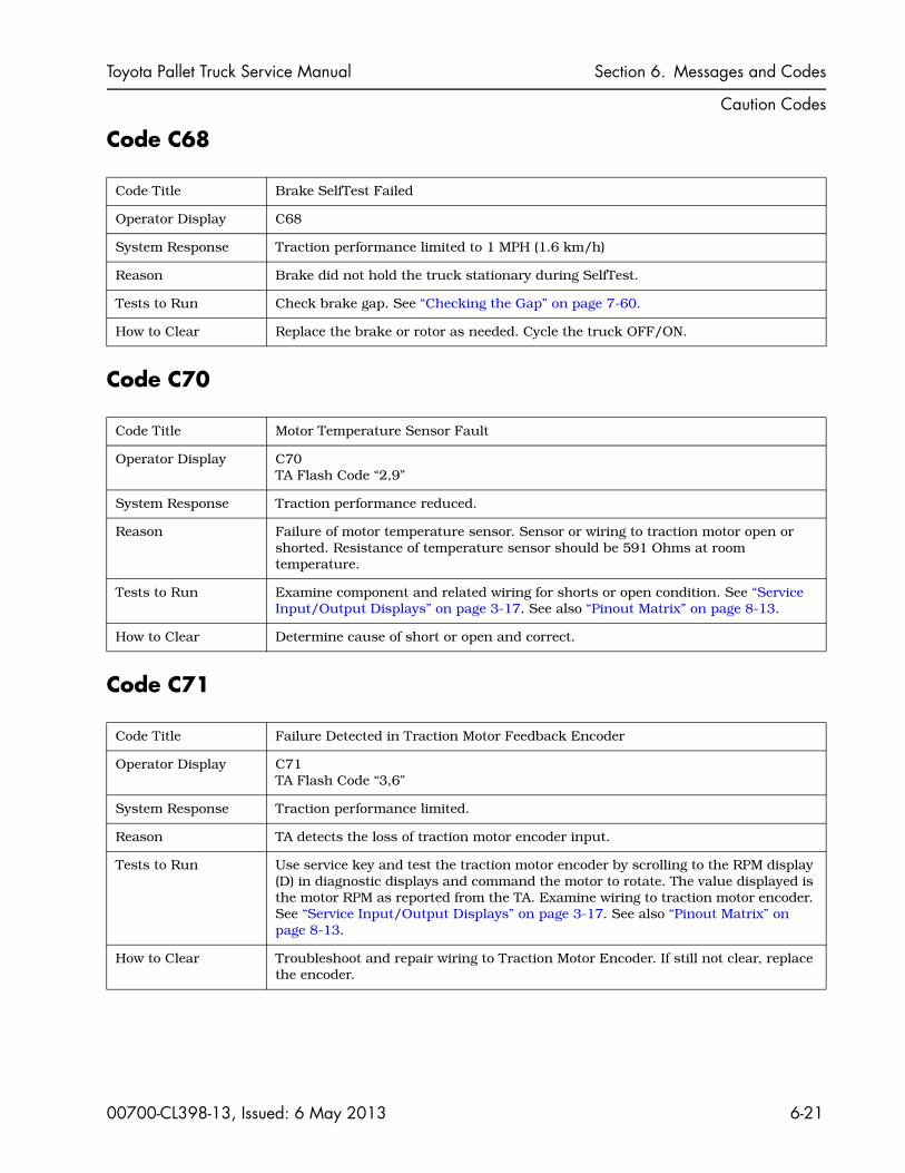
Code Title Brake SelfTest Failed
Operator Display C68
System Response Traction performance limited to 1 MPH (1.6 km/h)
Reason Brake did not hold the truck stationary during SelfTest.
Tests to Run Check brake gap. See “Checking the Gap” on page 7-60.
How to Clear Replace the brake or rotor as needed. Cycle the truck OFF/ON.
Code Title Motor Temperature Sensor Fault
Operator Display C70 TA Flash Code “2,9”
System Response Traction performance reduced.
Reason Failure of motor temperature sensor. Sensor or wiring to traction motor open or shorted. Resistance of temperature sensor should be 591 Ohms at room temperature.
Tests to Run Examine component and related wiring for shorts or open condition. See “Service Input/Output Displays” on page 3-17. See also “Pinout Matrix” on page 8-13.
How to Clear Determine cause of short or open and correct.
Code Title Failure Detected in Traction Motor Feedback Encoder
Operator Display C71 TA Flash Code “3,6”
System Response Traction performance limited.
Reason TA detects the loss of traction motor encoder input.
Tests to Run Use service key and test the traction motor encoder by scrolling to the RPM display (D) in diagnostic displays and command the motor to rotate. The value displayed is the motor RPM as reported from the TA. Examine wiring to traction motor encoder. See “Service Input/Output Displays” on page 3-17. See also “Pinout Matrix” on page 8-13.
How to Clear Troubleshoot and repair wiring to Traction Motor Encoder. If still not clear, replace the encoder.

Section 6. Messages and Codes Toyota Pallet Truck Service Manual
Caution Codes
6-22 00700-CL398-13, Issued: 6 May 2013
Code C72
Code C74 (Model 8TB50 with Power Steer)
Code C75 (Model 8TB50 with Power Steer)
Code Title Traction Motor Stalled
Operator Display C72 TA Flash Code “7,3”
System Response Traction performance limited until code cleared.
Reason TA detects that the traction motor has stalled.
Tests to Run Use service key and test the traction motor encoder by scrolling to the RPM display (D) in diagnostic displays and command the motor to rotate. The value displayed is the motor RPM as reported from the TA. See “Service Input/Output Displays” on page 3-17. See also “Pinout Matrix” on page 8-13.
How to Clear Cycle the truck OFF/ON.
Code Title Steer Unit Internal Error - General
Operator Display C74
System Response No steering. Truck plugged to stop. No Travel. Brake applied at 0 mph.
Reason Fault internal to steer unit.
Tests to Run None
How to Clear Error automatically cleared if possible when truck goes idle. If not, cycle the truck OFF/ON. If still not clear, replace the PSU controller.
Code Title Steer Unit Bus Voltage too Low (less than 12V)
Operator Display C75
System Response No steering. Truck plugged to stop. No Travel.
Reason Bad wiring or contactor, blown fuse.
Tests to Run None
How to Clear Error automatically cleared if possible when truck goes idle. Cycle the truck OFF/ON. If still not clear, replace the PSU controller.

Toyota Pallet Truck Service Manual Section 6. Messages and Codes
Caution Codes
00700-CL398-13, Issued: 6 May 2013 6-23
Code C76 (Model 8TB50 with Power Steer)
Code C77 (Model 8TB50 with Power Steer)
Code C78 (Model 8TB50 with Power Steer)
Code Title Steer Unit Bus Voltage too High (greater than 39 volts)
Operator Display C76
System Response No steering. Truck plugged to stop. No Travel.
Reason Incorrect battery installed or possibly bad steer unit.
Tests to Run Check battery voltage to the PSU.
How to Clear Make sure the correct voltage battery is installed. Error automatically cleared if possible when truck goes idle. If not, cycle the truck OFF/ON. Replace the PSU controller.
Code Title Steer Sensor 5V Power Supply Out-of-Range
Operator Display C77
System Response No steering. Truck plugged to stop. No Travel.
Reason Short in wiring.
Tests to Run Disconnect power steer sensor and check wiring for shorts.
How to Clear Error automatically cleared if possible when truck goes idle. If not, cycle the truck OFF/ON. Run learn steer. If the code does not clear then replace the PSU controller.
Code Title Steer Unit Calculated Temperature at 100% of Maximum or Steering is Stalled
Operator Display C78
System Response No steering. Truck plugged to stop. No travel.
Reason Excessive loading and/or mechanical binding.
Tests to Run 1. Check for mechanical binding.
2. Check motor current draw.
How to Clear Allow steer amplifier to cool. Replace the PSU.
sheath
Text Box
click here for more info on code 78

Section 6. Messages and Codes Toyota Pallet Truck Service Manual
Caution Codes
6-24 00700-CL398-13, Issued: 6 May 2013
Code C79 (Model 8TB50 with Power Steer)
Code C80 (Model 8TB50 with Power Steer)
Code Title Steer Unit Measured Temperature Warning, 80% of Maximum
Operator Display C79
System Response Reduced steering torque. No Travel slowdown.
Reason Excessive loading and/or mechanical binding.
Tests to Run 1. Check for mechanical binding.
2. Check motor current draw.
How to Clear Allow steer amplifier to cool. Replace the PSU.
Code Title Steer Unit Calculated Temperature Warning, 80% of Maximum
Operator Display C80
System Response Reduced steering torque. No Travel slowdown.
Reason Excessive loading and/or mechanical binding.
Tests to Run 1. Check for mechanical binding.
2. Check motor current draw.
How to Clear Allow steer amplifier to cool. Replace the PSU.
Toyota Pallet Truck Service Manual Section 6. Messages and Codes
Caution Codes
00700-CL398-13, Issued: 6 May 2013 6-25
Code C81 (Model 8TB50 with Power Steer)
Code C82 (Model 8TB50 with Power Steer)
Code C83 (Model 8TB50 with Power Steer)
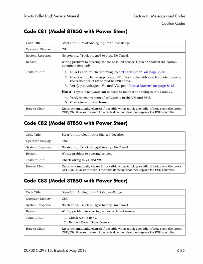
Code Title Steer Unit Sum of Analog Inputs Out-of-Range
Operator Display C81
System Response No steering. Truck plugged to stop. No Travel.
Reason Wiring problem to steering sensor or failed sensor. Open or shorted R2 (carbon potentiometers only).
Tests to Run 1. Run Learn on the steering. See “Learn Steer” on page 7-13.
2. Check wiring between pots and PSU. For trucks with a carbon potentiometer, the resistance of R2 should be 620 ohms.
3. Verify pot voltages, V1 and V2, per “Pinout Matrix” on page 8-13.
NOTE: Toyota FlashWare can be used to monitor the voltages of V1 and V2.
4. Verify correct version of software is in the VM and PSU.
5. Check for shorts to frame.
How to Clear Error automatically cleared if possible when truck goes idle. If not, cycle the truck OFF/ON. Run learn steer. If the code does not clear then replace the PSU controller.
Code Title Steer Unit Analog Inputs Shorted Together
Operator Display C82
System Response No steering. Truck plugged to stop. No Travel.
Reason Wiring problem to steering sensor.
Tests to Run Check wiring to V1 and V2.
How to Clear Error automatically cleared if possible when truck goes idle. If not, cycle the truck OFF/ON. Run learn steer. If the code does not clear then replace the PSU controller.
Code Title Steer Unit Analog Input V2 Out-of-Range
Operator Display C83
System Response No steering. Truck plugged to stop. No Travel.
Reason Wiring problem to steering sensor or failed sensor.
Tests to Run 1. Check wiring to V2.
2. Replace Power Steer Sensor.
How to Clear Error automatically cleared if possible when truck goes idle. If not, cycle the truck OFF/ON. Run learn steer. If the code does not clear then replace the PSU controller.
sheath
Text Box
Click here for more information on C81 Code
sheath
Text Box
Click here for info on Steer Pot

Section 6. Messages and Codes Toyota Pallet Truck Service Manual
Caution Codes
6-26 00700-CL398-13, Issued: 6 May 2013
Code C84 (Model 8TB50 with Power Steer)
Code C85 (Model 8TB50 with Power Steer)
Code C86 (Model 8TB50 with Power Steer)
Code Title Steer Unit Analog Input V1 Out-of-Range
Operator Display C84
System Response No steering. Truck plugged to stop. No Travel.
Reason Wiring problem to steering sensor or failed sensor.
Tests to Run 1. Check wiring to V1.
2. Replace Power Steer Sensor.
How to Clear Error automatically cleared if possible when truck goes idle. If not, cycle the truck OFF/ON. Run learn steer. If the code does not clear then replace the PSU controller.
Code Title Both Steer Unit Analog Inputs (V1 and V2) Out-of-Range
Operator Display C85
System Response No steering. Truck plugged to stop. No Travel.
Reason Wiring problem to steering sensor or failed sensor.
Tests to Run 1. Check wiring to V1 and V2.
2. Replace Power Steer Sensor.
How to Clear Error automatically cleared if possible when truck goes idle. If not, cycle the truck OFF/ON. Run learn steer. If the code does not clear then replace the PSU controller.
Code Title Steer Unit - Communication Failure
Operator Display C86
System Response No steering. Truck plugged to stop. No Travel.
Reason No power to steering unit, broken CAN bus wires, or failed steer unit.
Tests to Run 1. Check for B+ at JP9-6 and B– at JP9-7 and JP9-15.
2. Verify CAN bus wiring. See “Troubleshooting the CAN Bus” on page 5-6.
3. Check cable between PSU and steer sensor for shorts.
4. Disconnect sensors. If code changes, replace power steer sensor.
How to Clear Cycle the truck OFF/ON. Replace the PSU controller.

Toyota Pallet Truck Service Manual Section 6. Messages and Codes
Caution Codes
00700-CL398-13, Issued: 6 May 2013 6-27
Code C87 (Model 8TB50 with Power Steer)
Code C88 (Model 8TB50 with Power Steer)
Code C89 (Model 8TB50 with Power Steer)
Code Title Home Switch Supply Out-of-Range
Operator Display C87
System Response No steering. Truck plugged to stop. No travel.
Reason Bad wiring or failed home switch.
Tests to Run Check wiring and voltage to switch.
How to Clear Error automatically cleared if possible when truck goes idle. If not, cycle the truck OFF/ON. Replace switch.
Code Title Reference Run Error
Operator Display C88
System Response No steering. Truck plugged to stop. No Travel.
Reason Bad wiring, failed home switch, or failed steer unit.
Tests to Run Check wiring and voltage to switch.
How to Clear Cycle the truck OFF/ON. Replace switch. Replace the PSU controller.
Code Title Steering Response is less than Request
Operator Display C89
System Response Travel limited to 1 MPH (1.6 km/h)
Reason Binding drive unit and/or steering gears, failed steering unit.
Tests to Run Check for binding in the steer gears and steering unit.
How to Clear Error automatically cleared if possible when truck goes idle. If not, cycle the truck OFF/ON. Replace the PSU controller.
sheath
Text Box
Click here for more info on C88 code

Section 6. Messages and Codes Toyota Pallet Truck Service Manual
Caution Codes
6-28 00700-CL398-13, Issued: 6 May 2013
Code C90 (Model 8TB50 with Power Steer)
Code C94 (Model 8TB50 with Power Steer)
Code Title Steer Unit Internal Error - Shorted Phase
Operator Display C90
System Response No steering. Truck plugged to stop. No Travel.
Reason Fault Internal to Steer Unit.
Tests to Run None
How to Clear Error automatically cleared if possible when truck goes idle. If not, cycle the truck OFF/ON. If still not clear, replace the PSU controller.
Code Title Steer Unit Sum of Analog Inputs Warning Threshold Exceeded
Operator Display C94
System Response Travel Limited to approximately 1.73 MPH (2.8 km/h) and the horn will beep three times in rapid succession.
Reason Wiring problem to steering sensor or steer sensor intermittent.
Tests to Run 1. Run Learn on the steering. See “Learn Steer” on page 7-13.
2. Check wiring between pots and PSU. For trucks with a carbon potentiometer, the resistance of R2 should be 620 ohms.
3. Verify pot voltages, V1 and V2, following the “Pinout Matrix” on page 8-13.
NOTE: FlashWare can be used to monitor the voltages of V1 and V2.
4. Verify correct version of software is in the VM and PSU.
5. Check for shorts to frame.
How to Clear Error automatically cleared when the analog sum is back within threshold range when the handle is lifted to the brake position. If not, cycle the truck OFF/ON. Run learn steer. If the code does not clear then replace the PSU controller..
sheath
Text Box
Click here for more info on code C94
Toyota Pallet Truck Service Manual Section 6. Messages and Codes
Error Codes
00700-CL398-13, Issued: 6 May 2013 6-29
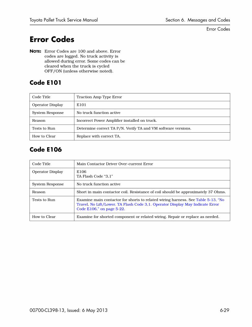
Error CodesNOTE: Error Codes are 100 and above. Error
codes are logged. No truck activity is allowed during error. Some codes can be cleared when the truck is cycled OFF/ON (unless otherwise noted).
Code E101
Code E106
Code Title Traction Amp Type Error
Operator Display E101
System Response No truck function active
Reason Incorrect Power Amplifier installed on truck.
Tests to Run Determine correct TA P/N. Verify TA and VM software versions.
How to Clear Replace with correct TA.
Code Title Main Contactor Driver Over-current Error
Operator Display E106 TA Flash Code “3,1”
System Response No truck function active
Reason Short in main contactor coil. Resistance of coil should be approximately 37 Ohms.
Tests to Run Examine main contactor for shorts to related wiring harness. See Table 5-13, “No Travel, No Lift/Lower. TA Flash Code 3,1. Operator Display May Indicate Error Code E106,” on page 5-22.
How to Clear Examine for shorted component or related wiring. Repair or replace as needed.

Section 6. Messages and Codes Toyota Pallet Truck Service Manual
Error Codes
6-30 00700-CL398-13, Issued: 6 May 2013
Code E107
Code E108
Code E140
Code Title Contactor Off Error
Operator Display E107 TA Flash Code “3,9”
System Response No truck function active
Reason Main contactor did not close. Open in main contactor coil.
Tests to Run Examine contactor circuit for opens in related wiring harness. See Table 5-16, “No Travel, Main Contactor Does Not Close. TA Flash Code 3,9. Operator Display Indicates Error Code E107,” on page 5-23. See “Service Input/Output Displays” on page 3-17. Examine for open Main Contactor or related wiring.
How to Clear Repair/replace as needed.
Code Title Contactor Weld Error
Operator Display E108 TA Flash Code “3,8”
System Response No truck function active
Reason Main Contactor welded (detected on start-up). Open in U phase of traction motor.
Tests to Run Inspect contact tips for welding. Check for B+ voltage at the B+ connection of the traction amplifier. See “Service Input/Output Displays” on page 3-17.
NOTE: Check the U cable for correct connection and continuity. An open in only the U circuit causes this code. An open in the V and W circuit causes codes E201 and E203.
Examine for welded contact tips.
How to Clear Repair/replace as needed.
Code Title Checksum Error
Operator Display E140
System Response No truck function active
Reason Software check sum not the same as the stored value.
Tests to Run None
How to Clear May clear on cycling key switch OFF/ON. Reload software in the VM. If not, replace the VM.

Toyota Pallet Truck Service Manual Section 6. Messages and Codes
Error Codes
00700-CL398-13, Issued: 6 May 2013 6-31
Code E141
Code E150
Code E157
Code Title Software Problem
Operator Display E141
System Response No truck function active
Reason VM internal error, or missing or faulty software due to a failure or problem while downloading. VM determined that software files were corrupt.
Tests to Run None
How to Clear Reload the software as allowed.
Code Title CAN Bus Communication Error
Operator Display E150
System Response No truck function active. Code may be displayed briefly then goes out.
Reason Grab rail (or load backrest) lift or lower switch active at power up. VM has not detected any response from TA to CAN messages. Bad connection or terminal crimp or a damaged wire between TA and VM. Check for low battery voltage. This can be caused by accidental activation (operator pressing the switches) at or during startup or pins 11 and 12 on the TA shorted to B+ (see codes C50, C51 and C52). Examine VM, TA, and related wiring.
Tests to Run See “Troubleshooting the CAN Bus” on page 5-6.
How to Clear Repair/replace as needed.
Code Title CAN Bus Off Error
Operator Display E157
System Response No truck function active
Reason TA did not reply to CAN messages.
Tests to Run See “Troubleshooting the CAN Bus” on page 5-6. Examine VM, TA, and related wiring.
How to Clear Repair/replace as needed.
sheath
Text Box
Click here for more info on E150 code
Section 6. Messages and Codes Toyota Pallet Truck Service Manual
Error Codes
6-32 00700-CL398-13, Issued: 6 May 2013
Code E159
Code E160
Code E201
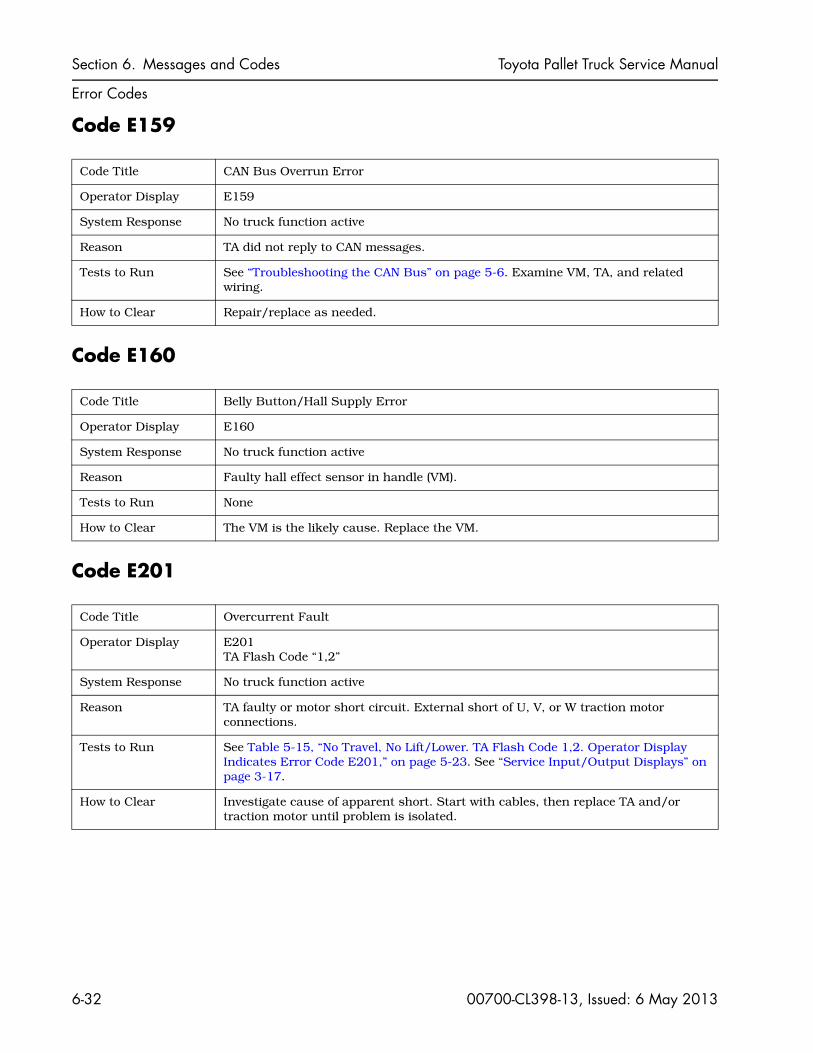
Code Title CAN Bus Overrun Error
Operator Display E159
System Response No truck function active
Reason TA did not reply to CAN messages.
Tests to Run See “Troubleshooting the CAN Bus” on page 5-6. Examine VM, TA, and related wiring.
How to Clear Repair/replace as needed.
Code Title Belly Button/Hall Supply Error
Operator Display E160
System Response No truck function active
Reason Faulty hall effect sensor in handle (VM).
Tests to Run None
How to Clear The VM is the likely cause. Replace the VM.
Code Title Overcurrent Fault
Operator Display E201 TA Flash Code “1,2”
System Response No truck function active
Reason TA faulty or motor short circuit. External short of U, V, or W traction motor connections.
Tests to Run See Table 5-15, “No Travel, No Lift/Lower. TA Flash Code 1,2. Operator Display Indicates Error Code E201,” on page 5-23. See “Service Input/Output Displays” on page 3-17.
How to Clear Investigate cause of apparent short. Start with cables, then replace TA and/or traction motor until problem is isolated.

Toyota Pallet Truck Service Manual Section 6. Messages and Codes
Error Codes
00700-CL398-13, Issued: 6 May 2013 6-33
Code E202
Code E203
Code E220
Code Title TA Current Sensor Error
Operator Display E202 TA Flash Code “1,3”
System Response No truck function active
Reason Phase current sensor fault.
Tests to Run See Table 5-14, “No Travel, No Lift/Lower. TA Flash Code 1,3. Operator Display Indicates Error Code E202,” on page 5-22. See “Service Input/Output Displays” on page 3-17.
How to Clear Investigate cause of apparent short. Start with cables, then replace TA and/or traction motor until problem is isolated.
Code Title Motor Open
Operator Display E203 TA Flash Code “3,7”
System Response No truck function active
Reason Motor phase V or W detected open. Bad power amplifier.
NOTE: An open in the U phase causes a code E108.
Tests to Run Examine motor and related wiring for open circuit. See “Service Input/Output Displays” on page 3-17.
How to Clear Repair cause of open circuit.
Code Title Default Parameters DNL
Operator Display E220 TA Flash Code “4,6”
System Response No truck function active
Reason TA default parameters did not load.
Tests to Run None
How to Clear Reload software if allowed.

Section 6. Messages and Codes Toyota Pallet Truck Service Manual
Error Codes
6-34 00700-CL398-13, Issued: 6 May 2013
Code E221
Code E222
Code E223
Code Title Severe Battery Undervoltage
Operator Display E221TA Flash Code “1,7”, Battery icon blinking
System Response No truck function active
Reason Severe battery undervoltage, under 12V.
Tests to Run Measure battery voltage and specific gravity. See Table 5-21, “No Truck Functions Active. TA Flash Code 1,7, (Low Battery Voltage). Operator Display May Indicate E221,” on page 5-24. See “Service Input/Output Displays” on page 3-17.
NOTE: Check for other codes and, if others are present, troubleshoot following those codes. (Failure of the M1 contactor circuit during operation causes this code to be shown along with E106 and E107.)
How to Clear Replace battery with fully-charged batter. A bad TA or bad wiring could also be the causey.
Code Title Severe Battery Overvoltage
Operator Display E222 TA Flash Code “1,8”, Battery icon blinking
System Response No truck function active
Reason Severe battery overvoltage; over 42V during run time or above 32V at key ON.
Tests to Run Measure battery voltage. See Table 5-20, “No Truck Functions Active. TA Flash Code 1,8, (Excessive Battery Voltage). Operator Display May Indicate E222,” on page 5-24. See “Service Input/Output Displays” on page 3-17.
How to Clear Install battery of correct voltage. A bad TA or bad wiring could also be the cause.
Code Title TA Severe Undertemperature Cutback
Operator Display E223 TA Flash Code “1,5”
System Response No truck function active
Reason TA heatsink temperature below minimum operating temperature (below –40°C/–40°F).
Tests to Run Test the temperature sensor. See “Service Input/Output Displays” on page 3-17.
How to Clear Warm truck to normal operating temperature and cycle the truck OFF/ON. Investigate to determine the cause of the undertemperature condition.

Toyota Pallet Truck Service Manual Section 6. Messages and Codes
Error Codes
00700-CL398-13, Issued: 6 May 2013 6-35
Code E224
Code E225
Code E228
Code Title TA Severe Overtemperature Cutback
Operator Display E224 TA Flash Code “1,6”
System Response No truck function active
Reason TA heatsink temperature over maximum operating temperature (+95°C/203°F).
Tests to Run Test temp sensor. See “Service Input/Output Displays” on page 3-17.
How to Clear Allow truck to cool. Investigate to determine the cause of the overheating.
Code Title Precharge Fault
Operator Display E225 TA Flash Code “1,4”
System Response No truck function active
Reason TA precharge circuit failed.
Tests to Run None
How to Clear Try cycling the truck OFF/ON. If that does not solve the problem, replace the TA.
Code Title Parameter Change Fault
Operator Display E228 TA Flash Code “4,9”
System Response No truck function active
Reason TA parameters have changed. Critical TA parameter changed while operating.
Tests to Run None
How to Clear Cycle the truck OFF/ON.

Section 6. Messages and Codes Toyota Pallet Truck Service Manual
Error Codes
6-36 00700-CL398-13, Issued: 6 May 2013
Code E230
Code E232
Code E233
Code Title External Supply Out-Of-Range
Operator Display E230 TA Flash Code “6,9”
System Response No truck function active
Reason External supply current out-of-range (+12V, +5V). Devices connected to these outputs on the TA are drawing too much current (> 250 mA).
Tests to Run Check all wiring and components connected to the 12 volts from the TA for shorts. If OK, check the wiring and encoder connected to JP1-26 for the traction motor for shorts.
How to Clear Cycle the truck OFF/ON. If not cleared by cycling the truck OFF/ON, try to determine what device caused the problem.
Code Title VCL Runtime
Operator Display E232 TA Flash Code “6,8”
System Response No truck function active
Reason Internal TA software error.
Tests to Run None
How to Clear Cycle the truck OFF/ON. Reinstall software if allowed.
Code Title +5V Supply Failure
Operator Display E233 TA Flash Code“2,5”
System Response No truck function active
Reason Controller +5V supply failed.
Tests to Run Check all wiring and components connected to the 12 volts from the TA for shorts. If OK, check the wiring and encoder connected to JP1-26 for the traction motor for shorts. See Code E230. See “Pinout Matrix” on page 8-13.
How to Clear Cycle the truck OFF/ON.

Toyota Pallet Truck Service Manual Section 6. Messages and Codes
Error Codes
00700-CL398-13, Issued: 6 May 2013 6-37
Code E235
Code E252
Code E253
Code Title NVM Reset Error
Operator Display E235
System Response No truck function active
Reason TA NVM (Non-Volatile Memory) error. TA Non-volatile memory corrupted, unable to reset.
Tests to Run None
How to Clear Try cycling the truck OFF/ON. If that does not solve the problem, replace the TA.
Code Title Not Speed Program
Operator Display E252
System Response No truck function active
Reason Detected Inputs/Outputs do not match the selected configuration.
Tests to Run None
How to Clear Truck may not be configured to match Sub Model type (Parameter 37). See “Programming Service Parameters” on page 3-9.
Code Title Invalid Sub Model
Operator Display E253
System Response No truck function active
Reason Detected Inputs/Outputs do not match the selected configuration.
Tests to Run None
How to Clear Truck may not be configured to match Sub Model type (Parameter 37). See “Programming Service Parameters” on page 3-9.
sheath
Text Box
Click here for more info on E235

Section 6. Messages and Codes Toyota Pallet Truck Service Manual
Error Codes
6-38 00700-CL398-13, Issued: 6 May 2013
This page intentionally left blank.

SERVICE INFORMATION BULLETIN Subject: ETAC Software Update Information and Descriptions Page 1 of 2
MODEL APPLICATION: 8HBW30, 8HBE30-40, 8HBC30-40 and 8TB50 GENERAL INFORMATION: Two new software versions are currently available and are downloadable from the TMHU Portal via TIS (Toyota Information System). REPAIR INFORMATION: This bulletin explains the software version information including a description of changes and additions to each software versions.
1. Error code C88 can be logged with older versions of PSU software. Loading a new version of code with Flashware should correct this issue. If loading the new version does not correct the C88 error code, the PSU must be replaced. 2. A Code C78 now causes the VM to command the truck to plug to a stop on tow tractors with Electric Steer. 3. Previous versions of software would not record or display two error codes that are detected by the power amp, E150 and E235. The traction system would shut down in these cases, but no error would be reported. This version now records and displays the errors. 4. Travel speed will now be consistent when in a slight turn with or without a load. 5. Auto steer center is now enacted any time the main contactor is disabled then re-enabled on an electric steer truck. If the throttle is engaged while an auto steer center is in progress, an HPd will be displayed. Traction is disabled until the throttle is returned to neutral. 6. The maximum steering angle on an Electric Steer tow tractor can be adjusted from 20 degrees through 80 degrees based on direction of travel (default is 80 degrees in both directions). Use parameter #22 for forks-first maximum steer angle and parameter #23 for tractor-first maximum steer angle. 7. Instances of nuisance error codes C74, C86, and C88 have been reduced on trucks equipped with a PSU.
Control Circuit CC13-001 January 15, 2013 ETAC Software Update Information and Descriptions 8HBW30, 8HBC(E)30-40 and 8TB50

Subject: ETAC Software Update Information and Descriptions Page 2 of 2
The following software is being used in current production effective serial numbers: 8HBW30-40402, 8HBE30-42456, 8HBE40-40109, 8HBC30-40089, 8HBC40-40014 and 8TB50-40629
1. Added a minimum delay of 400 milliseconds between back to back lifts to prevent contactor chatter. 2. Added more options to Travel Alarm (Parameter 16) so that travel and battery cutout alarm can occur at the same time on 8TB50 trucks. The battery cutout alarm sounds slightly different and takes priority over the travel alarm. 0=No Alarm 1=Tractor-First Travel 2=Forks-First Travel, 3=All Travel 4=Low Battery 5=Low Battery and Tractor-First Travel, 6=Low Battery and Forks-First Travel 7=Low Battery and All Travel 3. Changed the following on electric steer trucks: a. Reduced logging of C88 error codes by increasing the steering speed during auto steer center. b. Made steer centering more accurate. The time allowed for completion was also increased. c. Re-Enabled backlash parameter setting for electric steer tow tractors sent to the PSU from the VM when the key is turned ON to eliminate the clunking sound some tow tractors made when steering. 4. Parameter 11 will now show up on all 8HBC30-40 and 8TB50 trucks. On trucks without electric steer, the parameter must be set to 0 or the travel function will be disabled. 5. Added a drop down for Toyota 8HBC3040/8TB50 Trucks in FlashWare. Changed Truck code to automatically set/clear the Tow bit based on the configured model. Setting the Truck as Model 8HBC30/40 will clear the Tow bit. Setting the Truck as Model 8TB50 will set the Tow bit. 6. Added detection of LOS (Limited Operating Strategy) mode being reported by the Power Amp. This does not change truck functionality because the Amp is already limiting the truck speed, but now an error code will be displayed (Code 72) when the Truck is in LOS mode.

SERVICE INFORMATION BULLETIN Subject: 8TB50 Power Steering Software Update (v1.9) Page 1 of 1
MODEL APPLICATION:
8TB50 with Power Steering GENERAL INFORMATION: This bulletin is being distributed to notify dealers and field personnel of the following changes included in the ETAC software version 1.9 for the 8TB50 with power steering. The update includes:
• Addition of new Code C94. • Changes to Code C81
SERVICE INFORMATION: Flashware software file name is: 915A0019.s19. Install software 915A0019.s19 and PSU (Power Steer Unit) software 915A9160.s19 for the Code C94 to be enabled. If either of the new software versions are combined with an older software version, the C94 code will not be displayed. Code C94 information: Code C94 has been added to identify lower steer unit sum of analog inputs out-of-range conditions. See page 6-28 of the 8 series pallet truck service manual 00700-CL398-13 issued May 6, 2013 for troubleshooting information. C94 is similar to C81 except C94 attempts to detect the out-of-range condition sooner using a smaller range and where C81 will disable steering and plug the truck to a stop; C94 leaves the steering enabled and slows the truck to 1.7 mph. System Response in the event of a C94:
- The horn will beep three times in rapid succession. - Steering remains enabled but travel is de-rated to 1.7 mph. - If the out-of-range condition returns to normal before the handle is lifted to the brake
position, the code is cleared when the handle is lifted and normal operation is resumed. Change made to Code C81:
- If the out-of-range condition returns to normal while the truck is plugging to a stop, steering will be re-enabled.
Control Circuit CC13-005 May 31, 2013 8TB50 Power Steering Software Update (v1.9) 8TB50 with Power Steering

SERVICE INFORMATION BULLETIN Subject: C81 Code – Steer Potentiometer Page 1 of 9
MODEL APPLICATION:
8TB50 with Power Steering GENERAL INFORMATION: Some customers have reported code C81 at low hour meter readings. This code may be caused by the carbon steer potentiometer. A solid state potentiometer (P/N 00590-51016-71) is now available as a replacement. Follow the instructions on the following pages when replacing a carbon steer potentiometer with a solid state potentiometer. Use FlashWare and install VM software version 1.9 or higher (915A0019.s19) and PSU software version 160 or higher (915A9160.s19). Note: Please be sure to re-learn the steering using Flashware after installation. SERVICE INFORMATION: Steering Potentiometer Replacement instructions for Solid State Potentiometer 1. Remove the Control Handle (P/N 00590-50709-71): a. Remove the (4) screws around the bezel.
Chassis Electrical CE13-003 May 31, 2013 C81 Code – Steer Potentiometer 8TB50 with Power Steering

Subject: C81 Code – Steer Potentiometer Page 2 of 9 b. Lift the entire assembly out of the handle bracket.
c. The cable is retained in the bracket and can be removed by releasing the retainer at bottom of bracket. 2. Remove the (2) screws in the face of the cover. Remove the (2) screws on the side of the cover, then remove the cover.
Note: The screws in the plastic on the face are coarse thread, the screws in the side are fine thread. 3. Remove the (2) screws in the cover.

Subject: C81 Code – Steer Potentiometer Page 3 of 9
4. Remove the cover over the cable, cut the wire tie, and remove.
5. Remove the (4) screws indicated to separate the control handle. Unplug the (2) connectors on the harness, one from the side of the housing, one at the base of the handle. Cut the wire ties at the holders. Note where the cables were tied and length of the service loop left available. Remove the entire cable assembly and potentiometer. These will be replaced with the new Solid State Steering potentiometer/cable.
6. Connect the new potentiometer and cable assembly (P/N 00590-51016-71) to the housing and the proximity sensor cable. Use a wire tie to secure the cables to the yellow wire tie pad.

Subject: C81 Code – Steer Potentiometer Page 4 of 9
7. Rotate the wire tie so the end rests on either side of the cables but not on top for clearance reasons.
8. Reassemble in the upper handle with (4) screws. It is important to torque these screws to 12 in. lbs. (1.35 Nm). CAUTION: Over torqueing can cause throttle to bind. Test operation of the throttle to verify return to center when activated.

Subject: C81 Code – Steer Potentiometer Page 5 of 9
9. Assemble the upper handle assembly back into the mounting bracket. Push the cable retainer at the end of the new cable into the retainer hole in the bracket before lowering the handle. Route the cable between the front edge of the bracket and post on the lower bearing.
10. Insert the potentiometer into the cavity at the base of the handle.
11. The shaft of the potentiometer must engage the “D” shaped opening in the bottom bearing. Refer to the picture below to see the indexing feature on the lower bearing for the potentiometer.

Subject: C81 Code – Steer Potentiometer Page 6 of 9
12. Replace the two screws that mount the potentiometer with M3 x 16 mm screws (P/N 00590-51061-71). Apply thread-locking compound (P/N 00590-04864-71) to the screws. Install the cover over the loomed cable with the larger loom opening oriented out away from the handle and the smaller towards the handle. Make sure no wires are caught under the flanges of the cover when assembled.
13. Wire tie cables together as shown. Make sure to maintain a service loop for the handle to rotate up and down.

Subject: C81 Code – Steer Potentiometer Page 7 of 9
14. Replace the two lower covers.
15. Install the (4) screws around the perimeter of the top bezel. NOTE: Do Not use thread-locking compound on the bezel screws or near the plastic.
16. Replace the Resistor Module shown below with a jumper (P/N 00590-52188-71).

Subject: C81 Code – Steer Potentiometer Page 8 of 9
17. Inspect splices SPL11, SPL12, and SPL13 to verify complete crimps were performed.
Note: SPL11 can sometimes be buried in the center of the harness. Make sure there is a crimp on both the wire area and the insulation area of the splice.
If a crimp is weak or missing, manually crimp and document what needed to be done.

Subject: C81 Code – Steer Potentiometer Page 9 of 9
Replace any removed cable ties. 18. Install new Vehicle Manager software (version 1.9 or higher) into the truck using Flashware 5.5 or above. 19. Install new Power Steer Unit software (version 160 or higher) into the truck using Flashware 5.5 or above. 20. Relearn steering using Flashware 5.5 or above and test the function of the truck before returning the truck to service.

SERVICE INFORMATION BULLETIN Subject: Vehicle Manager and Traction Amp Software Updates Page 1 of 2
MODEL APPLICATION:
8HBW30, 8HBE30-40, 8HBC30-40, 8TB50 and 8TB50 with Power Steering GENERAL INFORMATION: This bulletin is being distributed to notify dealers and field personnel of a new software release for the Vehicle Manager (VM) and Traction Power Amplifier (TPA) on the above models. IMPORTANT:
• To install these software updates you must use Flashware 5.7 or later.
• On the 8HBC30-40 and 8TB50 with Power Steering if the PSU (Power Steer Unit) software is older than 915A9160.s19, please update accordingly as these software updates are designed to work together. (example of old PSU software: 915A9140 or 9150)
Flashware 5.7 and the s19 software files are available for download on TIS. Please remember to uninstall the current version of Flashware on your computer before installing the new version. SERVICE INFORMATION:
Control Circuit CC13-007 October 15, 2013 Vehicle Manager and Traction Amp Software Updates 8HBW30, 8HBE30-40, 8HBC30-40, 8TB50 and 8TB50 with Power Steering

Subject: Vehicle Manager and Traction Amp Software Updates Page 2 of 2
Summary of Changes included in these software updates: 1) Reduced the occurrence of C81 error codes by increasing some timeouts for the solid state
steer potentiometers by a factor of 10 (Changed from 2 ms to 20 ms). 2) Reduced the occurrence of C83 and C84 error codes on trucks with the solid state steer
potentiometers when the truck is powered on and the handle is not centered. 3) Reduced the occurrence of C74 error codes when the truck is powered on. 4) Disabled the Lift contactor driver check on Model 8TB50 trucks. 5) Changes were made to improve the reliability of the lift contactor which include a new
Traction Amplifier Flash Code, 5,3. It will be shown on the operator display as a Code C60 - Lift Contactor Coil (M2) Driver Shorted or Open. Troubleshooting in the repair manual for the Code C60 remains the same (See page 6-18 of manual 00700-CL398-13).
This change requires:
a) Flashware 5.7 or higher to update the TPA. b) The new VM sofware for the truck being updated (as shown in the table on page 1), and c) the updated Traction Amp sofware version 12.82.
6) Added error code E109 to indicate the failure of a device on the truck to respond to a CAN
message sent by the VM. The original code for this was C86. Use the C86 – Steer Unit Communication Failure information in the repair manual to troubleshoot a code E109. (See page 6-26 of manual 00700-CL398-13)
NOTE: Trucks produced after the following model-serial numbers will have these software updates.
• 8HBW30-40480 • 8HBE30-43112 • 8HBE40-40126 • 8HBC30-40108 • 8HBC40-40014 • 8TB50-40949

SERVICE INFORMATION BULLETIN Subject: Power Steer Unit Controller Repair Instructions Page 1 of 2 MODEL APPLICATION: Power Steer Models: 8HBE30, 8HBE40, 8HBC30, 8HBC40 and 8TB50 GENERAL INFORMATION: This bulletin is being released to announce that the power steer unit (PSU) controller is now available separately from the motor, gearbox and pinion gear and to provide instructions for how to replace the controller section of the power steer unit assembly.
Power Steer Unit Controller individual part (P/N 00590-50525-71) Motor, gearbox, and pinion gear without Controller (P/N 00590-50526-71)
SERVICE INFORMATION: In the Service Manual (00700-CL398-13) the following changes have been made:
Change the wording in Codes C74, C75, C76, C86, C88, C89, and C90 in the How to Clear section from “Replace the PSU” to “Replace the PSU Controller.”
Change the wording in Codes C77, C81, C82, C83, C84, C85, and C94 in the How to Clear section from “Replace the PSU” to “Run Learn Steer. If the code does not clear, then replace the PSU Controller.”
Added instructions for replacing the power steer unit controller on page 7-13 Please use the following procedures when removing and installing the controller. Removing and Installing the PSU Controller 1. Remove the PSU from the truck.
2. Place the PSU on a Static Mat. Put on the wrist strap and connect the ground cord to the mat.
3. Remove the two screws connecting the controller to the motor.
4. Grab the casing with the bare hand to avoid potential electrical differences between your body and the unit. NOTE: Do not wear gloves.
Control Circuit CC14-006 August 15, 2014 Power Steer Unit Controller Repair Instructions 8HBE30-40, 8HBC30-40, 8TB50
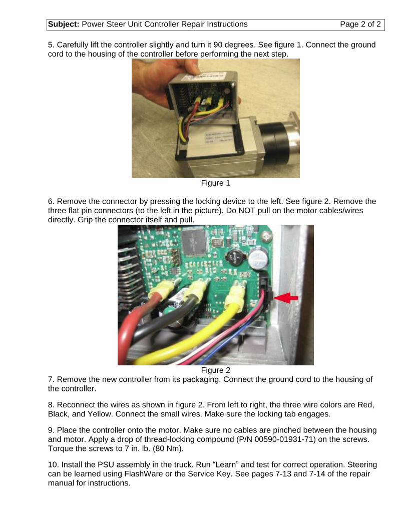
Subject: Power Steer Unit Controller Repair Instructions Page 2 of 2 5. Carefully lift the controller slightly and turn it 90 degrees. See figure 1. Connect the ground cord to the housing of the controller before performing the next step.
Figure 1
6. Remove the connector by pressing the locking device to the left. See figure 2. Remove the three flat pin connectors (to the left in the picture). Do NOT pull on the motor cables/wires directly. Grip the connector itself and pull.
Figure 2
7. Remove the new controller from its packaging. Connect the ground cord to the housing of the controller.
8. Reconnect the wires as shown in figure 2. From left to right, the three wire colors are Red, Black, and Yellow. Connect the small wires. Make sure the locking tab engages.
9. Place the controller onto the motor. Make sure no cables are pinched between the housing and motor. Apply a drop of thread-locking compound (P/N 00590-01931-71) on the screws. Torque the screws to 7 in. lb. (80 Nm).
10. Install the PSU assembly in the truck. Run “Learn” and test for correct operation. Steering can be learned using FlashWare or the Service Key. See pages 7-13 and 7-14 of the repair manual for instructions.