section 6 engine computor manual - Stephenson...
44
1. FUNCTIONAL SPECIFICATION . . . . . . . . . . . . . . . . . . . . . . . . . . . . . . . . . . . . . . . . . . . . . .6-2 1.1 GENERAL . . . . . . . . . . . . . . . . . . . . . . . . . . . . . . . . . . . . . . . . . . . . . . . . . . . . . . . . . . . . .6-2 1.2 EXTERNAL INTERFACES . . . . . . . . . . . . . . . . . . . . . . . . . . . . . . . . . . . . . . . . . . . . . . . .6-2 1.3 MAN MACHINE INTERFACE . . . . . . . . . . . . . . . . . . . . . . . . . . . . . . . . . . . . . . . . . . . . . .6-4 1.3.1 SHIFT LEVER . . . . . . . . . . . . . . . . . . . . . . . . . . . . . . . . . . . . . . . . . . . . . . . . . . .6-4 1.3.2 DISPLAY . . . . . . . . . . . . . . . . . . . . . . . . . . . . . . . . . . . . . . . . . . . . . . . . . . . . . . .6-4 1.3.3 OTHER . . . . . . . . . . . . . . . . . . . . . . . . . . . . . . . . . . . . . . . . . . . . . . . . . . . . . . . .6-5 1.4 OPERATING MODES . . . . . . . . . . . . . . . . . . . . . . . . . . . . . . . . . . . . . . . . . . . . . . . . . . . .6-6 1.4.1 NORMAL DRIVING . . . . . . . . . . . . . . . . . . . . . . . . . . . . . . . . . . . . . . . . . . . . . . .6-6 1.4.2 SELF TEST MODE . . . . . . . . . . . . . . . . . . . . . . . . . . . . . . . . . . . . . . . . . . . . . . .6-6 1.5 OPERATING CHARACTERISTICS . . . . . . . . . . . . . . . . . . . . . . . . . . . . . . . . . . . . . . . . . .6-6 1.5.1 SYSTEM . . . . . . . . . . . . . . . . . . . . . . . . . . . . . . . . . . . . . . . . . . . . . . . . . . . . . . .6-6 1.5.2 ON/OFF INPUTS . . . . . . . . . . . . . . . . . . . . . . . . . . . . . . . . . . . . . . . . . . . . . . . . .6-6 1.5.3 ANALOGUE INPUTS (NOT USED) . . . . . . . . . . . . . . . . . . . . . . . . . . . . . . . . . .6-7 1.5.4 SPEED SENSOR INPUTS . . . . . . . . . . . . . . . . . . . . . . . . . . . . . . . . . . . . . . . . .6-7 1.5.4.A TURBINE SPEED . . . . . . . . . . . . . . . . . . . . . . . . . . . . . . . . . . . . . . . . . . . . . .6-7 1.5.4.B ENGINE SPEED . . . . . . . . . . . . . . . . . . . . . . . . . . . . . . . . . . . . . . . . . . . . . . .6-7 1.5.4.C SENSOR CIRCUIT CHARACTERISTICS . . . . . . . . . . . . . . . . . . . . . . . . . . . .6-7 1.5.5 ON/OFF OUTPUTS . . . . . . . . . . . . . . . . . . . . . . . . . . . . . . . . . . . . . . . . . . . . . . .6-8 1.5.6 ANALOGUE OUTPUTS . . . . . . . . . . . . . . . . . . . . . . . . . . . . . . . . . . . . . . . . . . .6-8 1.6 FUNCTIONAL DESCRIPTION . . . . . . . . . . . . . . . . . . . . . . . . . . . . . . . . . . . . . . . . . . . . .6-8 1.6.1 EXTERNAL INPUTS . . . . . . . . . . . . . . . . . . . . . . . . . . . . . . . . . . . . . . . . . . . . . .6-8 1.6.1.A NOT IDLE/IDLE SWITCH (WIRE 19) . . . . . . . . . . . . . . . . . . . . . . . . . . . . . . .6-8 1.6.1.B MANUAL/AUTOMATIC SWITCH (WIRE 29) . . . . . . . . . . . . . . . . . . . . . . . . . .6-8 1.6.1.B.1 MANUAL AUTOMATIC . . . . . . . . . . . . . . . . . . . . . . . . . . . . . . . . . . . . . . . . .6-8 1.6.1.B.2 AUTOMATIC MANUAL . . . . . . . . . . . . . . . . . . . . . . . . . . . . . . . . . . . . . . . . .6-8 1.6.1.C LOCKUP ENABLED/DISABLED (WIRE 22) . . . . . . . . . . . . . . . . . . . . . . . . . .6-9 1.6.1.D DECLUTCH REQUEST INACTIVE/ACTIVE (WIRE 30) . . . . . . . . . . . . . . . . .6-9 1.6.2 SHIFT LEVER . . . . . . . . . . . . . . . . . . . . . . . . . . . . . . . . . . . . . . . . . . . . . . . . . . .6-9 1.6.3 OVERSPEEDING UPSHIFTS AS TRANSMISSION PROTECTION . . . . . . . .6-10 1.6.4 AUTOMATIC SHIFTING . . . . . . . . . . . . . . . . . . . . . . . . . . . . . . . . . . . . . . . . . .6-10 1.6.4.A AUTOMATIC SHIFTING IN NEUTRAL . . . . . . . . . . . . . . . . . . . . . . . . . . . . .6-10 1.6.4.B DEFINITIONS . . . . . . . . . . . . . . . . . . . . . . . . . . . . . . . . . . . . . . . . . . . . . . . .6-10 1.6.4.C AUTOMATIC SHIFTING (IF IN 'CONVERTER DRIVE') . . . . . . . . . . . . . . . .6-11 1.6.4.D AUTOMATIC SHIFTING (IF IN 'BRAKING MODE') . . . . . . . . . . . . . . . . . . .6-20 1.6.4.E LOCKUP ENGAGEMENT (IF IN 'CONVERTER DRIVE') . . . . . . . . . . . . . .6-20 1.6.4.F LOCKUP DISENGAGEMENT (IF IN 'LOCKUP DRIVE') . . . . . . . . . . . . . . .6-20 1.6.4.G AUTOMATIC UPSHIFTS (IF IN 'LOCKUP DRIVE') . . . . . . . . . . . . . . . . . . .6-20 1.6.5 OUTPUT FEATURES . . . . . . . . . . . . . . . . . . . . . . . . . . . . . . . . . . . . . . . . . . . .6-20 1.6.5.A WARNING LAMP OUTPUT (WIRE 3) . . . . . . . . . . . . . . . . . . . . . . . . . . . . .6-20 1.6.5.B CONTROL VALVE OUTPUTS (WIRE 6, 7, 4, 5, 9) . . . . . . . . . . . . . . . . . . .6-21 Section 6 ENGINE COMPUTER MANUAL 6- 1 785 Motor Grader TABLE OF CONTENTS PAGE
Transcript of section 6 engine computor manual - Stephenson...

1. FUNCTIONAL SPECIFICATION . . . . . . . . . . . . . . . . . . . . . . . . . . . . . . . . . . . . . . . . . . . . . .6-21.1 GENERAL . . . . . . . . . . . . . . . . . . . . . . . . . . . . . . . . . . . . . . . . . . . . . . . . . . . . . . . . . . . . .6-21.2 EXTERNAL INTERFACES . . . . . . . . . . . . . . . . . . . . . . . . . . . . . . . . . . . . . . . . . . . . . . . .6-2
1.3 MAN MACHINE INTERFACE . . . . . . . . . . . . . . . . . . . . . . . . . . . . . . . . . . . . . . . . . . . . . .6-41.3.1 SHIFT LEVER . . . . . . . . . . . . . . . . . . . . . . . . . . . . . . . . . . . . . . . . . . . . . . . . . . .6-41.3.2 DISPLAY . . . . . . . . . . . . . . . . . . . . . . . . . . . . . . . . . . . . . . . . . . . . . . . . . . . . . . .6-41.3.3 OTHER . . . . . . . . . . . . . . . . . . . . . . . . . . . . . . . . . . . . . . . . . . . . . . . . . . . . . . . .6-5
1.4 OPERATING MODES . . . . . . . . . . . . . . . . . . . . . . . . . . . . . . . . . . . . . . . . . . . . . . . . . . . .6-61.4.1 NORMAL DRIVING . . . . . . . . . . . . . . . . . . . . . . . . . . . . . . . . . . . . . . . . . . . . . . .6-61.4.2 SELF TEST MODE . . . . . . . . . . . . . . . . . . . . . . . . . . . . . . . . . . . . . . . . . . . . . . .6-6
1.5 OPERATING CHARACTERISTICS . . . . . . . . . . . . . . . . . . . . . . . . . . . . . . . . . . . . . . . . . .6-61.5.1 SYSTEM . . . . . . . . . . . . . . . . . . . . . . . . . . . . . . . . . . . . . . . . . . . . . . . . . . . . . . .6-61.5.2 ON/OFF INPUTS . . . . . . . . . . . . . . . . . . . . . . . . . . . . . . . . . . . . . . . . . . . . . . . . .6-61.5.3 ANALOGUE INPUTS (NOT USED) . . . . . . . . . . . . . . . . . . . . . . . . . . . . . . . . . .6-71.5.4 SPEED SENSOR INPUTS . . . . . . . . . . . . . . . . . . . . . . . . . . . . . . . . . . . . . . . . .6-71.5.4.A TURBINE SPEED . . . . . . . . . . . . . . . . . . . . . . . . . . . . . . . . . . . . . . . . . . . . . .6-71.5.4.B ENGINE SPEED . . . . . . . . . . . . . . . . . . . . . . . . . . . . . . . . . . . . . . . . . . . . . . .6-71.5.4.C SENSOR CIRCUIT CHARACTERISTICS . . . . . . . . . . . . . . . . . . . . . . . . . . . .6-71.5.5 ON/OFF OUTPUTS . . . . . . . . . . . . . . . . . . . . . . . . . . . . . . . . . . . . . . . . . . . . . . .6-81.5.6 ANALOGUE OUTPUTS . . . . . . . . . . . . . . . . . . . . . . . . . . . . . . . . . . . . . . . . . . .6-8
1.6 FUNCTIONAL DESCRIPTION . . . . . . . . . . . . . . . . . . . . . . . . . . . . . . . . . . . . . . . . . . . . .6-81.6.1 EXTERNAL INPUTS . . . . . . . . . . . . . . . . . . . . . . . . . . . . . . . . . . . . . . . . . . . . . .6-81.6.1.A NOT IDLE/IDLE SWITCH (WIRE 19) . . . . . . . . . . . . . . . . . . . . . . . . . . . . . . .6-81.6.1.B MANUAL/AUTOMATIC SWITCH (WIRE 29) . . . . . . . . . . . . . . . . . . . . . . . . . .6-81.6.1.B.1 MANUAL AUTOMATIC . . . . . . . . . . . . . . . . . . . . . . . . . . . . . . . . . . . . . . . . .6-81.6.1.B.2 AUTOMATIC MANUAL . . . . . . . . . . . . . . . . . . . . . . . . . . . . . . . . . . . . . . . . .6-81.6.1.C LOCKUP ENABLED/DISABLED (WIRE 22) . . . . . . . . . . . . . . . . . . . . . . . . . .6-91.6.1.D DECLUTCH REQUEST INACTIVE/ACTIVE (WIRE 30) . . . . . . . . . . . . . . . . .6-91.6.2 SHIFT LEVER . . . . . . . . . . . . . . . . . . . . . . . . . . . . . . . . . . . . . . . . . . . . . . . . . . .6-91.6.3 OVERSPEEDING UPSHIFTS AS TRANSMISSION PROTECTION . . . . . . . .6-101.6.4 AUTOMATIC SHIFTING . . . . . . . . . . . . . . . . . . . . . . . . . . . . . . . . . . . . . . . . . .6-101.6.4.A AUTOMATIC SHIFTING IN NEUTRAL . . . . . . . . . . . . . . . . . . . . . . . . . . . . .6-101.6.4.B DEFINITIONS . . . . . . . . . . . . . . . . . . . . . . . . . . . . . . . . . . . . . . . . . . . . . . . .6-101.6.4.C AUTOMATIC SHIFTING (IF IN 'CONVERTER DRIVE') . . . . . . . . . . . . . . . .6-111.6.4.D AUTOMATIC SHIFTING (IF IN 'BRAKING MODE') . . . . . . . . . . . . . . . . . . .6-201.6.4.E LOCKUP ENGAGEMENT (IF IN 'CONVERTER DRIVE') . . . . . . . . . . . . . .6-201.6.4.F LOCKUP DISENGAGEMENT (IF IN 'LOCKUP DRIVE') . . . . . . . . . . . . . . .6-201.6.4.G AUTOMATIC UPSHIFTS (IF IN 'LOCKUP DRIVE') . . . . . . . . . . . . . . . . . . .6-201.6.5 OUTPUT FEATURES . . . . . . . . . . . . . . . . . . . . . . . . . . . . . . . . . . . . . . . . . . . .6-201.6.5.A WARNING LAMP OUTPUT (WIRE 3) . . . . . . . . . . . . . . . . . . . . . . . . . . . . .6-201.6.5.B CONTROL VALVE OUTPUTS (WIRE 6, 7, 4, 5, 9) . . . . . . . . . . . . . . . . . . .6-21
Section 6ENGINE COMPUTER MANUAL
6- 1785 Motor Grader
TABLE OF CONTENTS PAGE

1.7 DIRECTION CHANGE PROTECTIONS . . . . . . . . . . . . . . . . . . . . . . . . . . . . . . . . . . . . .6-211.7.1 FORWARD - REVERSE OR REVERSE - FORWARD . . . . . . . . . . . . . . . . . .6-211.7.2 NEUTRAL - FORWARD OR NEUTRAL - REVERSE . . . . . . . . . . . . . . . . . . .6-221.7.3 FORWARD - NEUTRAL - FORWARD . . . . . . . . . . . . . . . . . . . . . . . . . . . . . .6-22
1.8 DOWNSHIFT PROTECTION . . . . . . . . . . . . . . . . . . . . . . . . . . . . . . . . . . . . . . . . . . . . . .6-22
2. SAFETY RELATED REQUIREMENTS . . . . . . . . . . . . . . . . . . . . . . . . . . . . . . . . . . . . . . . .6-22
2.1 APPLICABLE SAFETY GUIDELINES . . . . . . . . . . . . . . . . . . . . . . . . . . . . . . . . . . . . . . .6-22
2.2 SAFETY CONCEPT . . . . . . . . . . . . . . . . . . . . . . . . . . . . . . . . . . . . . . . . . . . . . . . . . . . .6-222.2.1 GENERAL . . . . . . . . . . . . . . . . . . . . . . . . . . . . . . . . . . . . . . . . . . . . . . . . . . . .6-222.2.2 APC72 IMPLEMENTATION . . . . . . . . . . . . . . . . . . . . . . . . . . . . . . . . . . . . . . .6-23
2.3 CONSIDERED FAULTS . . . . . . . . . . . . . . . . . . . . . . . . . . . . . . . . . . . . . . . . . . . . . . . . . .6-232.4 BEHAVIOR IN CASE OF FAULTS . . . . . . . . . . . . . . . . . . . . . . . . . . . . . . . . . . . . . . . . . .6-24
2.4.1 GENERAL . . . . . . . . . . . . . . . . . . . . . . . . . . . . . . . . . . . . . . . . . . . . . . . . . . . .6-242.4.2 RESET CONDITION . . . . . . . . . . . . . . . . . . . . . . . . . . . . . . . . . . . . . . . . . . . .6-242.4.3 OVERVOLTAGE . . . . . . . . . . . . . . . . . . . . . . . . . . . . . . . . . . . . . . . . . . . . . . . .6-242.4.4 UNDERVOLTAGE . . . . . . . . . . . . . . . . . . . . . . . . . . . . . . . . . . . . . . . . . . . . . . .6-242.4.5 PROGRAM OUT OF CONTROL . . . . . . . . . . . . . . . . . . . . . . . . . . . . . . . . . . .6-252.4.6 INTERMITTENT POWER LOSS . . . . . . . . . . . . . . . . . . . . . . . . . . . . . . . . . . .6-252.4.7 SINGLE FAULTS ON OUTPUTS . . . . . . . . . . . . . . . . . . . . . . . . . . . . . . . . . . .6-252.4.8 INCORRECT INPUT PATTERNS . . . . . . . . . . . . . . . . . . . . . . . . . . . . . . . . .6-26 2.4.9 SPEED SENSOR FAILURE . . . . . . . . . . . . . . . . . . . . . . . . . . . . . . . . . . . . . . .6-262.4.10 INDICATION OF FAULTS . . . . . . . . . . . . . . . . . . . . . . . . . . . . . . . . . . . . . . . .6-27
2.5 BEHAVIOR WHEN FAULTS ARE REMOVED . . . . . . . . . . . . . . . . . . . . . . . . . . . . . . . . .6-282.5.1 INTERNAL FAULTS . . . . . . . . . . . . . . . . . . . . . . . . . . . . . . . . . . . . . . . . . . . . .6-282.5.2 PROGRAM OUT OF CONTROL . . . . . . . . . . . . . . . . . . . . . . . . . . . . . . . . . . .6-282.5.3 SINGLE FAULTS ON OUTPUTS . . . . . . . . . . . . . . . . . . . . . . . . . . . . . . . . . . .6-282.5.4 INCORRECT INPUT PATTERNS . . . . . . . . . . . . . . . . . . . . . . . . . . . . . . . . . . .6-282.5.5 INTERMITTENT POWER LOSS . . . . . . . . . . . . . . . . . . . . . . . . . . . . . . . . . . .6-282.5.6 SPEED SENSOR FAILURE . . . . . . . . . . . . . . . . . . . . . . . . . . . . . . . . . . . . . . .6-29
2.6 SPECIFIC MEASURES TO GUARANTEE FAULT TOLERANCE . . . . . . . . . . . . . . . . . .6-29
2.7 MEASURES TO PROTECT FROM EXTERNAL FACTORS . . . . . . . . . . . . . . . . . . . . . .6-292.7.1 IDENTIFICATION . . . . . . . . . . . . . . . . . . . . . . . . . . . . . . . . . . . . . . . . . . . . . . .6-292.7.2 TRACEABILITY AND CONFIGURATION CONTROL . . . . . . . . . . . . . . . . . . .6-302.7.3 SOURCING . . . . . . . . . . . . . . . . . . . . . . . . . . . . . . . . . . . . . . . . . . . . . . . . . . .6-302.7.4 SOFTWARE . . . . . . . . . . . . . . . . . . . . . . . . . . . . . . . . . . . . . . . . . . . . . . . . . . .6-31
3. ENVIRONMENTAL CONDITIONS . . . . . . . . . . . . . . . . . . . . . . . . . . . . . . . . . . . . . . . . . . .6-313.1 NATURE OF ENVIRONMENTAL CONDITIONS . . . . . . . . . . . . . . . . . . . . . . . . .6-313.2 BEHAVIOR OF THE SYSTEM UNDER CERTAIN CONDITIONS . . . . . . . . . . .6-313.3 ENVIRONMENTAL STANDARDS AND LIMITS . . . . . . . . . . . . . . . . . . . . . . . . .6-313.4 INTERFERENCE IMMUNITY STANDARDS AND LIMITS . . . . . . . . . . . . . . . . .6-32
785 Motor Grader6- 2
Section 6ENGINE COMPUTER MANUAL

4. DEVELOPMENT REQUIREMENTS . . . . . . . . . . . . . . . . . . . . . . . . . . . . . . . . . . . . . . . . . .6-324.1 SPECIAL REQUIREMENTS FOR DESIGN AND IMPLEMENTATION . . . . . . . .6.324.2 DESIGN AND DEVELOPMENT TOOLS . . . . . . . . . . . . . . . . . . . . . . . . . . . . . . .6-32
5. GUIDELINES AND CONDITIONS FOR USE . . . . . . . . . . . . . . . . . . . . . . . . . . . . . . . . . . .6-33
5.1 DIAGNOSTICS AND MAINTENANCE . . . . . . . . . . . . . . . . . . . . . . . . . . . . . . . . . . . . . .6-335.1.1 GENERAL . . . . . . . . . . . . . . . . . . . . . . . . . . . . . . . . . . . . . . . . . . . . . . . . . . . .6-335.1.2 SELF TEST FUNCTIONS . . . . . . . . . . . . . . . . . . . . . . . . . . . . . . . . . . . . . . . .6-335.1.2.A SELF TEST OPERATION . . . . . . . . . . . . . . . . . . . . . . . . . . . . . . . . . . . . . . .6-345.1.2.B TURBINE SPEED MONITOR . . . . . . . . . . . . . . . . . . . . . . . . . . . . . . . . . . . .6-345.1.2.C ENGINE SPEED MONITOR . . . . . . . . . . . . . . . . . . . . . . . . . . . . . . . . . . . .6-345.1.2.D SPEED RATIO MONITOR . . . . . . . . . . . . . . . . . . . . . . . . . . . . . . . . . . . . . .6-355.1.2.E UPSHIFT SPEED RATIO . . . . . . . . . . . . . . . . . . . . . . . . . . . . . . . . . . . . . . .6-355.1.2.F DOWNSHIFT SPEED RATIO . . . . . . . . . . . . . . . . . . . . . . . . . . . . . . . . . . . .6-355.1.2.G BATTERY VOLTAGE MONITOR . . . . . . . . . . . . . . . . . . . . . . . . . . . . . . . . .6-365.1.2.H INPUT TEST . . . . . . . . . . . . . . . . . . . . . . . . . . . . . . . . . . . . . . . . . . . . . . . .6-365.1.2.I OUTPUT TEST . . . . . . . . . . . . . . . . . . . . . . . . . . . . . . . . . . . . . . . . . . . . . . .6-385.1.2.J ANALOG INPUT MONITOR . . . . . . . . . . . . . . . . . . . . . . . . . . . . . . . . . . . . .6-39
5.2 TECHNICAL GUIDELINES FOR INSTALLATION . . . . . . . . . . . . . . . . . . . . . . . . . . . . .6-395.2.1 POWER SUPPLY . . . . . . . . . . . . . . . . . . . . . . . . . . . . . . . . . . . . . . . . . . . . . . .6-405.2.2 INPUT SIGNALS . . . . . . . . . . . . . . . . . . . . . . . . . . . . . . . . . . . . . . . . . . . . . . .6-415.2.3 OUTPUT SIGNALS . . . . . . . . . . . . . . . . . . . . . . . . . . . . . . . . . . . . . . . . . . . . .6-415.2.4 COMMUNICATION INTERFACES . . . . . . . . . . . . . . . . . . . . . . . . . . . . . . . . . .6-415.2.4.A CAN LINK (TC28,TC17): INTERFACE . . . . . . . . . . . . . . . . . . . . . . . . . . . . .6-415.2.4.B TUNING LINK (TC08,TC28) . . . . . . . . . . . . . . . . . . . . . . . . . . . . . . . . . . . .6-41
6. REVISION RECORD . . . . . . . . . . . . . . . . . . . . . . . . . . . . . . . . . . . . . . . . . . . . . . . . . . . . .6-42
Section 6ENGINE COMPUTER MANUAL
6- 3785 Motor Grader

1. Functional specification1.1 General
The APC72 is a device used to control the shifting of many Spicer Off-Highway Powershift transmis-
sions. While being easy to operate, it takes care of all transmission related functions in order to
achieve superior shift quality and high reliability.
The built in self-test and trouble shooting features allow fast problem resolution.
The integration in the vehicle wiring system is straightforward and mainly involves connections
between the shift selector, the APC72 and the transmission control valve.
Additionally the APC72 requires some connections for supplying power and for selection of different
operating modes. Refer to section 5.2 for details about the installation.
1.2 External interfacesThe APC72 is connected to the vehicle wiring system using a 30 pole Packard Electric Metripack Connector.
The mating connector has following components and Packard part numbers:
785 Motor Grader6- 4
Section 6ENGINE COMPUTER MANUAL
Generic Transmission Controller APC72
Part Packard Part number Receptacle 12048455 Contact 12089290 (0.35-0.5 mm²) 12103881 (0.8 - 1.0 mm²)

The different connector pin functions for the APC72 are listed below.
Following type designations are considered:
Below table all references to terminals have prefix TC meaning they refer to the APC72 connector pins.
APC72 CONNECTIONS
Section 6ENGINE COMPUTER MANUAL
6- 5785 Motor Grader
Ptg pull to ground input internally pulled high, must be connected to Ground to activate
Ptp pull to plus input internally pulled low, must be connected to Plus to activate
Stg switch to ground Output switches internally to Ground. Other side of Load must be connected with Plus
Stp switch to plus Output switches internally to Battery plus. Other side of Load must be connected with Ground
TC01 A1 Battery + 12V/24V Connect to Battery through 6 A fuse TC02 B1 Ground Connect to chassis Ground TC03 C1 PWM0 stg Warning lamp TC04 D1 Solenoid 1 stp Gear position selection solenoid (1) TC05 E1 Solenoid 2 stp Gear position selection solenoid (2) TC06 F1 Forward Solenoid stp Forward / Neutral selection solenoid TC07 G1 Reverse Solenoid stp Reverse / Neutral selection solenoid TC08 H1 PWM1 stg Lockup solenoid TC09 J1 Splitter Solenoid stp Gear position selection solenoid (splitter)TC10 K1 PWM solenoid supply stp PWM solenoid supply TC11 A2 Battery + 12V Connect to Bat+ : for 12 V applications
only TC12 B2 Signal Ground For speed sensors only TC13 C2 Input 0 ptp Shift lever Forward input TC14 D2 Input 1 ptp Shift lever Reverse input TC15 E2 Input 3 ptp Shift lever range selection TC16 F2 RXD (RS232) Not used TC17 G2 CAN H Not used TC18 H2 Input 4 ptp Shift lever range selection TC19 J2 Input 6 ptp Not idle / Idle input TC20 K2 Analogue input 1 ptg Not used TC21 A3 Engine speed Engine speed - inductive pickup TC22 B3 Input 7 Lockup Enabled / Disabled TC23 C3 Turbine speed Turbine speed – inductive pickup TC24 D3 Not used Not used TC25 E3 Input 2 ptp Shift lever range selection TC26 F3 Output8 stp Not used TC27 G3 TXD (RS232) Not used TC28 H3 CAN L Not used TC29 J3 Input 5 ptp Manual/automatic switch TC30 K3 Analogue input 0 ptg Declutch Request Inactive (2000 ohm)/
Active (1000 ohm)
Wire Pin Function Type Comment

1.3 Man Machine interface
1.3.1 Shift lever
The main interface with the driver is the shift lever. It allows selecting the driving direction and the
different ranges. The shift lever output signals serve as inputs for the APC72.
1.3.2 Display
The display is located on the APC72 front panel and consists of:
2 red 7-segment LED digits
2 status LED lamps
a push button labeled 'M' for display mode selection.
The LED lamp labeled 'T' is yellow and is used to indicate test modes and faults.
The LED lamp labeled 'F' is red and is switched on when the APC72 is in the reset condition (see also
section 2.4.2).
APC72 front panel display
Refer to Dana drawing I/APC72A for installation dimensions.
After power up, the display defaults to the gear position mode. In this mode, the left digit shows
the actually engaged direction and the right digit shows the currently engaged range (gear).
785 Motor Grader6- 6
Section 6ENGINE COMPUTER MANUAL
M
T F

Pressing the 'M' switch changes the displayed information.
While pushing the switch (and about 1 second after it is released) the display shows which informa-
tion is about to be displayed.
Four modes listed in below table are available:
Pushing the switch activates the next mode. Pushing while in shift lever display, the gear position
display is again selected.
When holding the switch for more than 2 seconds, the display shows a code identifying the severest
problem currently detected, if any. The T-led flashes while an error is detected.
Error codes are described in section 2.4.10.
1.3.3 Other
Additionally several on/off switches with function described in section 1.6.1 are used to select differ-
ent operating functions.
Section 6ENGINE COMPUTER MANUAL
6- 7785 Motor Grader
While pressed Info shown Comment
This mode shows actually engaged direction and range. If either or both differ from the shift lever, the corresponding dot blinks. The example shows Neutral 1st.
This mode shows vehicle speed in km/h. For speeds below 10km/h, speed is shown with 0.1km/h resolution. The example shows 4.2km/h
This mode shows vehicle speed in mph. For speeds below 10mph, speed is shown with 0.1mph resolution. The example shows 4.2mph
This mode shows the current shift lever position. Only positions actually available on the transmission are shown. If different from the transmission, the corresponding dot blinks.

1.4 Operating modes
1.4.1 Normal driving
See 1.6 for detailed description
1.4.2 Self test mode
This mode is selected when the mode switch is pressed at power up.
See 5.1.2 for detailed description.
1.5 Operating CharacteristicsThe APC72 is designed to operate continuously under the environmental conditions described in sec-
tion 3.3.
Below sections detail some specific system limits and specification data relevant for interfacing with
the APC72.
1.5.1 System
The APC72 is designed for operation at 12V and at 24V without modifications to the controller.
1.5.2 On/Off inputs
785 Motor Grader6- 8
Section 6ENGINE COMPUTER MANUAL
Operating temperature range -40°C to +80°C Sealing IP65 & IP66 Supply Voltage Vnom Min - max.
12V 9V - 16V DC
Supply Voltage Vnom Min - max.
24V 18V - 32V DC
Over voltage conditions 5 min @ 48V 350ms @ 226V 2 ms @ 300V
Maximum continuous total load current @ Vnom
6 Amperes
Low input level < 0.8 V High input level > 2.3V Minimum DC voltage level - 60V Maximum DC voltage level +60V

1.5.3 Analogue inputs (not used)
1.5.4 Speed sensor inputs
1.5.4.a Turbine speed
The APC72 has two input circuits for sensing turbine speed - a current loop circuit compatible with
the Dana Magneto Resistive Sensor (MRS) and an inductive pickup input circuit. This way it's com-
patible with all existing sensor options on Dana transmissions.
The B.R. Lee LB22K Motor Grader uses an inductive speed sensor to measure transmission speed.
The controller only supports electrical fault detection for the MRS (short circuit or open load).
1.5.4.b Engine speed
For sensing engine speed, the APC72 accepts all existing Dana inductive speed pickups.
1.5.4.c Sensor circuit characteristics
Section 6ENGINE COMPUTER MANUAL
6- 9785 Motor Grader
Internal pull up resistor (to battery voltage)
11 kOhm
Input voltage range 0 to 5 V Resolution 10 bit Minimum DC voltage level - 60V Maximum DC voltage level +60V
Sensor type Magneto resistive Inductive Electrical interface Current sensing Voltage sensing Normal operating levels 7 / 14 mA 0.8 / 1.2 Vtt Short circuit detect yes No Open circuit detect yes no Reverse polarity detect seen as short ckt N.A. Fully protected yes yes
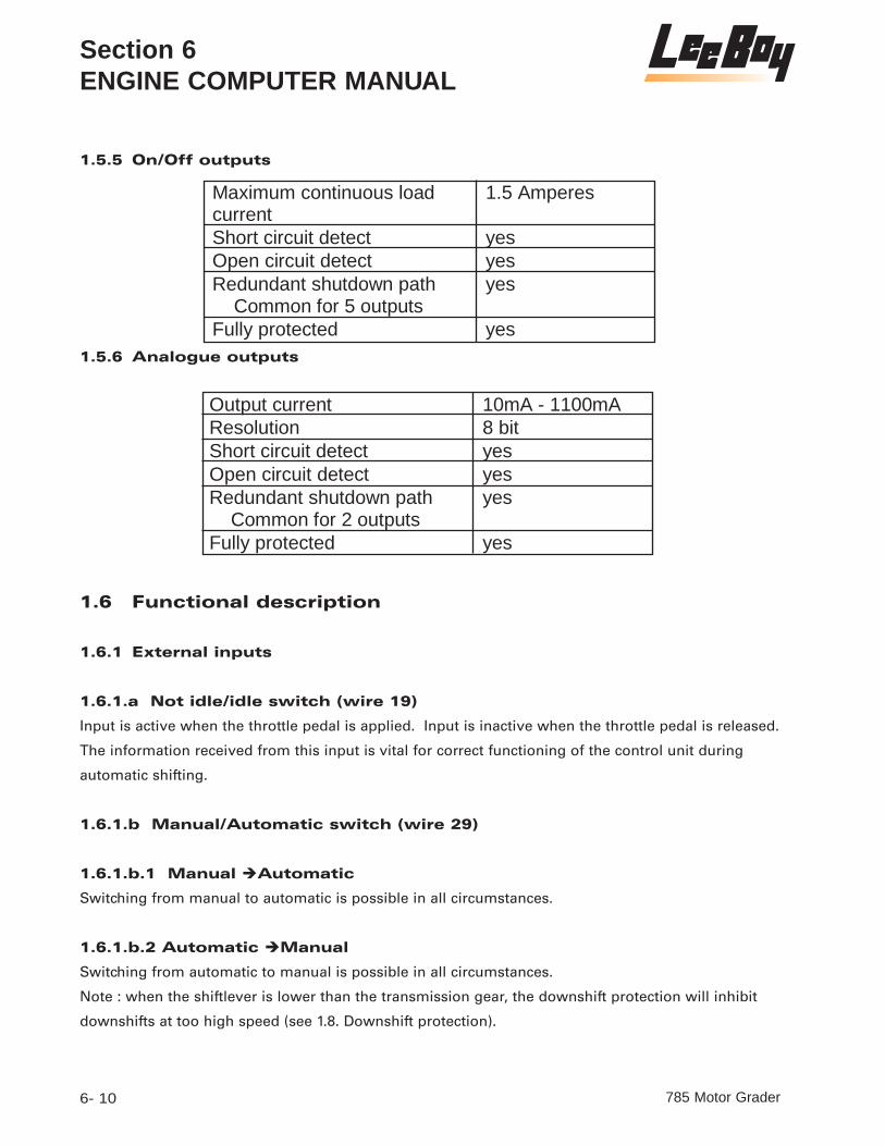
1.5.5 On/Off outputs
1.5.6 Analogue outputs
1.6 Functional description
1.6.1 External inputs
1.6.1.a Not idle/idle switch (wire 19)
Input is active when the throttle pedal is applied. Input is inactive when the throttle pedal is released.
The information received from this input is vital for correct functioning of the control unit during
automatic shifting.
1.6.1.b Manual/Automatic switch (wire 29)
1.6.1.b.1 Manual Automatic
Switching from manual to automatic is possible in all circumstances.
1.6.1.b.2 Automatic Manual
Switching from automatic to manual is possible in all circumstances.
Note : when the shiftlever is lower than the transmission gear, the downshift protection will inhibit
downshifts at too high speed (see 1.8. Downshift protection).
785 Motor Grader6- 10
Section 6ENGINE COMPUTER MANUAL
Maximum continuous load current
1.5 Amperes
Short circuit detect yes Open circuit detect yes Redundant shutdown path Common for 5 outputs
yes
Fully protected yes
Output current 10mA - 1100mA Resolution 8 bit Short circuit detect yes Open circuit detect yes Redundant shutdown path Common for 2 outputs
yes
Fully protected yes

1.6.1.c Lockup enabled/disabled (wire 22)
Lockup can be enabled and disabled with a switch on wire 22. If wire 22 is activated, lockup is
enabled. If wire 22 is not activated, lockup is disabled.
1.6.1.d Declutch Request inactive/active (wire 30)
A request for Declutch is made with a switch under the brake pedal on wire 30. The switch is normal-
ly closed and thus the analog input measures 2000 ohms. Resistance greater than 1800 ohms yields
an inactive request. Conversely opening the switch by depressing the brake pedal will yield 1000
ohms and thus an active request for declutch. Declutch is only granted when the vehicle speed is
below 2.3 MPH.
1.6.2 Shift lever
The main interface with the driver is the shift lever. It allows selecting the driving direction and the
different ranges. The shift lever output signals serve as inputs for the APC72.
The APC72 is designed to interface with a 6 speed shift lever that generates a grey coded selection
pattern as shown in below table.
= Wire connected to pin 1 of standard shift lever (BAT +)
Section 6ENGINE COMPUTER MANUAL
6- 11785 Motor Grader
Selected Position Standard Shift lever: wire number
1 2 3 4 5 6 7 13 F1 BAT + F2 BAT + F3 BAT + F4 BAT + F5 BAT + F6 BAT + N1 2&3 connected N1 BAT + R1 BAT + R2 BAT + R3 BAT +

In manual mode, the transmission gear will equal the shiftlever position, provided the downshift pro-
tection is not engaged (see 1.8. Downshift Protection).
In automatic mode, there will be automatic shifting between 1st gear and the shiftlever position.
Connections to the APC72
1.6.3 Overspeeding upshifts as transmission protection
In automatic mode, when the shiftlever position is higher than the transmission gear and the turbine
speed exceeds the overspeeding limit of 3000 RPM, an automatic upshift will occur to protect the
transmission against overspeeding.
1.6.4 Automatic shifting
1.6.4.a Automatic shifting in neutral
If the transmission is in neutral, the control unit will shift to the next higher gear when the transmis-
sion overspeeding limit is reached (3000 rpm) or will shift down when the transmission input speed
after the downshift would not exceed 1800 RPM.
1.6.4.b Definitions
If lockup is engaged, the transmission is in 'lockup drive'.
If lockup is not engaged, and speed ratio is below 1, the transmission is in 'converter drive' :
If lockup is not engaged, and speed ratio is above 1, the transmission is in 'braking mode' :
785 Motor Grader6- 12
Section 6ENGINE COMPUTER MANUAL
1 <
speed engine
speed turbine = ratio speed
1 > speed engine
speed turbine = ratio speed
Wire Standard shift lever
Wire on APC72
6 13 7 14 4 25 5 15 13 18

1.6.4.c Automatic shifting (if in 'converter drive')
automatic upshifting
An automatic shift to a higher gear is made when the throttle pedal is pressed, the turbine speed
exceeds a minimum turbine speed of 1500 RPM and the slip in the converter (speed ratio) has
reached a certain value. This occurs when the tractive effort in the higher gear is higher than the
tractive effort in the lower gear. The graphs below show both the upshift curve used for each gear.
Section 6ENGINE COMPUTER MANUAL
6- 13785 Motor Grader
Shift F1 --> F2
0.66
0.68
0.7
0.72
0.74
0.76
0.78
0.8
1300 1400 1500 1600 1700 1800 1900 2000
Trpm
Sp
eed
Rat
io

785 Motor Grader6- 14
Section 6ENGINE COMPUTER MANUAL
Shift F2 --> F3
0.73
0.74
0.75
0.76
0.77
0.78
0.79
0.8
0.81
1400 1500 1600 1700 1800 1900 2000 2100
Trpm
Sp
eed
Rat
io
Shift F3 --> F4
0.68
0.7
0.72
0.74
0.76
0.78
0.8
1300 1400 1500 1600 1700 1800 1900 2000
Trpm
Sp
eed
Rat
io

Section 6ENGINE COMPUTER MANUAL
6- 15785 Motor Grader
Shift F4 --> F5
0.71
0.72
0.73
0.74
0.75
0.76
0.77
0.78
0.79
0.8
1300 1400 1500 1600 1700 1800 1900 2000 2100
Trpm
Sp
eed
Rat
io

785 Motor Grader6- 16
Section 6ENGINE COMPUTER MANUAL
Shift R1 --> R2
0.79
0.8
0.81
0.82
0.83
0.84
0.85
1500 1600 1700 1800 1900 2000 2100 2200
Trpm
Sp
eed
Rat
io
Shift F5 --> F6
0.68
0.7
0.72
0.74
0.76
0.78
0.8
1300 1400 1500 1600 1700 1800 1900 2000
Trpm
Sp
eed
Rat
io

automatic downshifting
An automatic shift to a lower gear is made when the tractive effort in the lower gear exceeds the
tractive effort in the higher gear.
Following curves show the downshift curves for all gears.
Section 6ENGINE COMPUTER MANUAL
6- 17785 Motor Grader
Shift R2 --> R3
0.78
0.79
0.8
0.81
0.82
0.83
0.84
1500 1600 1700 1800 1900 2000 2100 2200
Trpm
Sp
eed
Rat
io

785 Motor Grader6- 18
Section 6ENGINE COMPUTER MANUAL
Shift F3 --> F2
0.36
0.38
0.4
0.42
0.44
0.46
750 800 850 900 950 1000 1050 1100 1150 1200
Trpm
Sp
eed
Rat
io
Shift F2 --> F1
0.42
0.44
0.46
0.48
0.5
0.52
0.54
900 950 1000 1050 1100 1150 1200 1250 1300 1350 1400
Trpm
Sp
eed
Rat
io

Section 6ENGINE COMPUTER MANUAL
6- 19785 Motor Grader
Shift F4 --> F3
0.42
0.44
0.46
0.48
0.5
0.52
0.54
900 950 1000 1050 1100 1150 1200 1250 1300 1350 1400
Trpm
Sp
eed
Rat
io

785 Motor Grader6- 20
Section 6ENGINE COMPUTER MANUAL
Shift F6 --> F5
0.42
0.44
0.46
0.48
0.5
0.52
0.54
900 950 1000 1050 1100 1150 1200 1250 1300 1350 1400
Trpm
Sp
eed
Rat
io
Shift F5 --> F4
0.38
0.4
0.42
0.44
0.46
0.48
0.5
800 850 900 950 1000 1050 1100 1150 1200 1250 1300
Trpm
Sp
eed
Rat
io

Section 6ENGINE COMPUTER MANUAL
6- 21785 Motor Grader
Shift R3 --> R2
0.29
0.3
0.31
0.32
0.33
0.34
0.35
640 680 720 760 800 840 880 920
Trpm
Sp
eed
Rat
io
Shift R2 --> R1
0.26
0.27
0.28
0.29
0.3
0.31
0.32
600 640 680 720 760 800 840 880
Trpm
Sp
eed
Rat
io

1.6.4.d Automatic shifting (if in 'braking mode')
automatic upshift
No automatic upshifts are allowed in braking mode (throttle pedal released). The only condition in
which an upshift is made during braking mode is when the transmission overspeeding limit is
reached and the shift lever indicates a gear higher than the one selected on the transmission. (see
1.6.3. Overspeeding Upshifts as transmission protection).
automatic downshift
Since the downshifts based upon speed ratio would take a very long time (because the engine speed
is low), the turbine speed must be also very low before a downshift based upon speed ratio's would
take place. In order to overcome this long period in which no downshift is made, braking downshifts
can be incorporated in the program. When the engine speed drops below 1000 RPM and the vehicle
speed drops below 500 RPM, a braking downshift is made.
1.6.4.e Lockup engagement (if in 'converter drive')
In 'idle position' of the throttle pedal (see not idle/idle switch on wire 19), lockup engages at 1650
RPM of the turbine. In 'not idle position' of the throttle pedal (see not idle/idle switch on wire 19),
lockup engages at 1750 RPM of the turbine.
1.6.4.f Lockup disengagement (if in 'lockup drive')
In 'idle position' of the throttle pedal (see not idle/idle switch on wire 19), lockup disengages at 1350
RPM of the turbine. In 'not idle position' of the throttle pedal (see not idle/idle switch on wire 19),
lockup engages at 1450 RPM of the turbine.
1.6.4.g Automatic upshifts (if in 'lockup drive')
Automatic upshifts in 'lockup drive' occur at 2300 RPM.
1.6.5 Output features
1.6.5.a Warning lamp output (wire 3)
When a downshift request, a forward - reverse request, a reverse - forward request, a neutral - for-
785 Motor Grader6- 22
Section 6ENGINE COMPUTER MANUAL

ward request, a neutral - reverse request, a forward - neutral - forward request or reverse - neutral -
reverse request is not granted due to too high vehicle speed or engine speed, or when the transmis-
sion is overspeeding, the warning lamp output (wire 3) switches on.
1.6.5.b Control valve outputs (wire 6, 7, 4, 5, 9)
Wires TC06, TC07, TC04, TC05 and TC09 are used to control the transmission. The table below reflects
the gear pattern generated in each of the transmission gears.
1.7 Direction change protections1.7.1 Forward - Reverse or Reverse - Forward
The behavior of the transmission during direction changes depends on the vehicle speed.
If the vehicle speed is below 1 km/h and the engine speed below 1000 RPM, the direction change will
be executed immediately. The new gear after a direction change will be :
> 1st in automatic mode
> equal to the shift lever position in manual mode
If the vehicle speed is too high (above 1 km/h) or the engine speed is above 1000 RPM, the direction
change will be not be executed and the transmission will be put in neutral until the vehicle speed
has dropped below 1 km/h and the engine speed has dropped below 1000 RPM. Then the new gear
after a direction change will be :
Section 6ENGINE COMPUTER MANUAL
6- 23785 Motor Grader
Transmission gear TC06 TC07 TC04 TC05 TC09 F1 F2 F3 F4 F5 F6 N1 N3 N5 R1 R3 R5

> 1st in automatic mode
> equal to the shift lever position in manual mode
1.7.2 Neutral - Forward or Neutral - Reverse
A Neutral - Forward or Neutral - Reverse action occurs when Forward or Reverse is selected out of
Neutral after machine standstill. In case of a Neutral - Forward or Neutral - Reverse action, Forward
or Reverse will only be put on the transmission if the engine speed is lower than 1000 RPM and the
vehicle speed is lower than 1 km/h.
1.7.3 Forward - Neutral - Forward or Reverse - Neutral - Reverse
A Forward - Neutral - Forward or Reverse - Neutral - Reverse action occur if a Forward - Neutral -
Forward selection or Reverse - Neutral - Reverse selection has been executed with the shiftlever and
the vehicle has not been standing still in neutral.
A Forward - Neutral - Forward or Reverse - Neutral - Reverse action will only be executed if the
engine speed is lower than 1000 RPM. This includes engagements following Declutch.
1.8 Downshift Protection
When a downshift is requested at high speed (in manual mode or in automatic mode) and the turbine
speed would exceed the transmission limit in the lower gear (exceeding 3000 RPM), the downshift is
not executed and the warning lamp switches on.
2. Safety related requirements
2.1 Applicable safety guidelines
The control system was designed and developed in close adherence to DIN/VDE801.
2.2 Safety concept
2.2.1 General
The safety concept is based on the control system's safety classification according to DIN19250
and on the definition of the Fail Safe State for a powershift transmission used in earth moving
equipment.
The applicable safety class requires considering single faults affecting driver safety and a redundant
method to achieve the fail safe state in case of a single safety critical fault.
785 Motor Grader6- 24
Section 6ENGINE COMPUTER MANUAL

For earth moving equipment acceptable fault conditions are considered to be:
- Fail to higher range
- Fail to next lower range
The fail safe state (to be attained when all else fails) is:
- Fail to neutral
2.2.2 APC72 implementation
The transmission concept mechanically prevents simultaneously locking of two conflicting clutches
and guarantees Fail To Neutral in case of electrical power loss.
These properties are used in the APC72 to implement the safety concept.
It monitors its inputs and outputs permanently in order to detect internal and external faults.
All faults are reported within 0.5 seconds, but only safety critical faults are acted upon.
Faults resulting in range shifts and loss of drive are tolerated.
Faults resulting in unwanted direction clutch engagement result in immediate selection of neu-
tral using the available redundant shutdown method.
Some other faults are tolerated but the performance of the system is crippled when the fault persists.
2.3 Considered faults
Over voltage
Under voltage
Internal faults
Program out of control
Single faults on outputs
Incorrect input patterns
Intermittent power loss
Speed sensor failure
Section 6ENGINE COMPUTER MANUAL
6- 25785 Motor Grader

2.4 Behavior in case of faults
2.4.1 General
It's considered critical to be able to select Neutral in all circumstances.
Selection of Neutral is also considered the safe state in case of many faults.
The APC72 has been designed to guarantee automatic selection of Neutral in some conditions. This
is accomplished through use of two separate watchdog timers and a redundant shutdown path for
outputs.
2.4.2 Reset Condition
When power is applied, the APC72 first selects the highest gear and starts initializing itself. This
includes a series of self tests to assure system integrity.
The highest gear is believed to be the safest possible condition in case of an intermittent power failure.
The initialization phase takes about 1 second.
After power up, the APC72 is in the so called Neutral Lock state. This means that the transmission
remains in Neutral until the shift lever is cycled physically through Neutral.
2.4.3 Overvoltage
The APC72 is very tolerant to large transients on its power lines (see also 3.4).
Even power supply levels up to 30 V will not damage circuit components in 12V mode.
For 24V mode, supply levels can go as high as 50V without damaging the controller.
However in case of 12V operation a supply voltage exceeds 18Vdc, or if the 12V/24V supply input is
left unconnected, the controller responds by issuing a fault and switches itself into high voltage mode
until the high voltage is removed. Nevertheless, in 12V mode, the controller will accept sustained
voltages up to 36 V.
In 24V mode, voltages in excess of 34V will be flagged as fault. For supply voltages in excess of 42V,
the controller will protect itself by turning outputs off (or back on at even higher voltages).
2.4.4 Undervoltage
In 12V mode the APC72 operates at voltages well below 9 Vdc. To achieve this however it's important
that both supply inputs are connected (12V AND 12V/24V).
785 Motor Grader6- 26
Section 6ENGINE COMPUTER MANUAL

Below 8Vdc however the APC72 enters the reset condition and shuts off all outputs.
For 24V operation, the same applies but the lower reliable operating voltage is 18V.
The under voltage condition is signalled as a 'battery low fault'. The controller will not reset until
the operating voltage drops below approximately 12V (but solenoids will not work well below 18V).
Because the APC72 is not involved in functions essential to engine cranking this is not considered as
a problem.
2.4.5 Program out of control
The watchdog timers reset the APC72 automatically if due to a program disturbance the watchdog
timers aren't reset in time (150 ms).
Additionally, during program execution, critical variables are continuously checked for contents
integrity. If faults are detected, the APC72 defaults to the reset state.
2.4.6 Intermittent power loss
After power is restored, the APC72 enters the reset condition, resulting in the immediate selection of
the highest gear.
In absence of power the transmission defaults to neutral. This is due to the transmission design and
has nothing to do with the APC72.
2.4.7 Single faults on outputs
General
If any ON/OFF output is shorted to ground, the fault is shown on the display
but no further action is taken. The background for this is that a short on an output always results in
switching the load off. This either forces Neutral or a shift to a higher range.
Direction selection related outputs (TC06,TC07) :
A short to plus is considered as a critical fault. Shorts to plus usually result in being blocked in
either Forward or Reverse (If both are on simultaneously, the transmission behavior depends on the
state of a hydro-mechanical interlock inside the transmission).
In this case, the APC72 cuts off the power to its power switches using the redundant shutdown path in
order to bring the transmission to neutral (this only helps if the APC72 itself is the cause of the problem).
Section 6ENGINE COMPUTER MANUAL
6- 27785 Motor Grader

This response prevents the APC72 from further monitoring the outputs. Therefor once it
enters this condition, it remains blocked in it until power is cycled off and on.
Other ON/OFF outputs:
Shorts to plus or open load conditions on these outputs are not considered to cause a safety hazard
and are tolerated. Usually however open load conditions are mistaken for shorts to plus (due to hard-
ware limitations) and are then treated accordingly.
The faults are indicated on the display as any output related fault.
Analogue solenoid related faults (TC03,TC08) :
Shorts to plus or ground and open load conditions on analogue outputs are not considered to cause
a safety hazard and are tolerated.
Whether faults can be detected depends on the normal load of the output. If a VFS (variable force
solenoid) with a coil resistance of about 4 Ohms is used, faults can reliably be detected.
A short to ground is signalled as an open circuit fault.
2.4.8 Incorrect input patterns
The shift lever pattern presented to the APC72 is continuously check for plausibility.
Direction selection related inputs:
If both Forward and Reverse are requested simultaneously, Neutral is selected.
Single 'stuck on' faults of either input are not recognized and result in a valid input signal, probably
causing the 'faulty' direction to be engaged.
Range selection related inputs:
In case a shift lever pattern is generated on the inputs which does not have a matching pattern in the
internal table (see 1.6.2), the pattern is ignored and the last known shift lever position is taken into
consideration.
2.4.9 Speed sensor failure
An electrical speed sensor failure can be detected when using a MRS (magneto resistive sensor).
If a speed sensor fault is detected, no automatic downshifts are allowed. As soon as the error disap-
pears, the automatic downshift is granted again.
785 Motor Grader6- 28
Section 6ENGINE COMPUTER MANUAL

In case of an inductive sensor, electrical fault detection on the sensor is not possible.
2.4.10 Indication of faults
When a fault is detected, the T-led starts flashing.
In order to find out which fault was last detected hold the 'M' switch for more than 2 seconds. The
display will then show alternately the fault area and the fault type. If several faults coexist, only the
severest one is shown.
Below table lists faults in order of severity (severest fault on top) along with displayed codes.
Section 6ENGINE COMPUTER MANUAL
6- 29785 Motor Grader
Fault Fault area Fault Type Direction outputs shutdown (latched)
Direction outputs forced to plus
Direction outputs open connection
MRS Speed sensor failure open connection
MRS Speed sensor failure short circuit
Inductive Speed sensor failure
Digital output short circuit
Digital output other fault
Incorrect input pattern

2.5 Behavior when faults are removed
2.5.1 Internal faults
Not applicable, because internal faults are only checked at power up
2.5.2 Program out of control
Not applicable, because this fault results in APC72 reset
2.5.3 Single faults on outputs
2.5.4 Incorrect input patterns
Normal operation is resumed.
2.5.5 Intermittent power loss
Not Applicable, because this fault results in APC72 reset
785 Motor Grader6- 30
Section 6ENGINE COMPUTER MANUAL
Battery voltage too low
12V input voltage too high
12V/24V input voltage missing
24V input voltage too high
Short to ground normal operation is resumed Direction outputs : Shutdown condition
Neutral remains selected until the APC72 is reset (power off/on)
Direction outputs : Short to plus
normal operation is resumed after ±0.5 sec
Any fault on other ON/OFF outputs normal operation is resumed
Fault Response after fault removal

2.5.6 Speed sensor failure
Normal operation is resumed.
2.6 Specific measures to guarantee Fault toleranceOperational
The control system must be installed according to the requirements and instructions stated on the
appropriate customer specific wiring diagram. It shall not be operated outside the environmental
conditions defined in 3.3 and 3.4.
In case a fault is signalled, the vehicle must be serviced in order to find and correct the cause of the
problem.
Production Test
During the production cycle, all units receive following tests:
Visual inspection of Printed Circuit Boards and finished product
Functional test at nominal load and nominal power supply
Minimum operating voltage @ 20°C is verified
Speed sensor input function over complete operating voltage range
Communication link test and check of programmed EEPROM parameters
Other
2.7 Measures to protect from external factors
2.7.1 Identification
Each APC72 unit is marked with a label showing following items:
Spicer Off-Highway
Serial Number
Dana Spicer Off-Highway Part Number
Program version reference
Each Printed Circuit Board shows following items:
SOH part number of the assembled board,
Board Revision Number
Board issue date
Section 6ENGINE COMPUTER MANUAL
6- 31785 Motor Grader

2.7.2 Traceability and configuration control
A permanent record of above information along with other information relevant for production and
service is kept in the Dana Spicer Off-Highway Bruges Controls department.
Design and implementation details of each hardware revision is available in a structured format
showing following information:
Reason for change
Revision date, and release date
Impact study of change
Reference to the revision it's based on
Circuit Diagram with changes marked
Layout plots
List of changes with references to the relevant drawings
Related correspondence with manufacturer
Design and implementation details of each released software version is available in a structured for-
mat showing following information:
Original problem analysis (or reference to it)
Reason for change
Revision date, and release date
Impact study of change
Reference to the revision it's based on
Program source code or references to untouched modules
List of changes with reference to reason for change
Test report of the new release
Related correspondence with customer
2.7.3 Sourcing
Spicer Off-Highway is the only supplier for the APC72 described in this document.
All shipped units are produced, tested and inspected by the Controls group of the Dana Spicer Off-
Highway plant located in Brugge (Belgium Europe). This guarantees strict conformance to above stat-
ed identification and traceability requirements.
785 Motor Grader6- 32
Section 6ENGINE COMPUTER MANUAL

2.7.4 Software
Communication services are disabled during normal operation. Modifications to APC72 parameters
are only possible with the shift lever in neutral.
The APC72 contains tables of boundaries limiting the range of modification of EEPROM parameters,
in order to assure safe values for limits at all times.
3. Environmental conditions3.1 Nature of environmental conditions
The APC72 is intended to be used on mobile earth moving and material handling machinery and
as such is exposed to the severe environmental conditions these machines operate in.
The APC72 should be installed inside the driver's cabin, protected from direct exposure to rain, dust
and direct steam cleaning.
3.2 Behavior of the system under certain conditions
The built in On/Off outputs will automatically shut off in case their junction temperature exceeds
150°C. This can be caused by external short circuits of outputs to ground, but also by over-current
conditions when the unit is operated at high temperature. After cooling down, they automatically
retry to drive their load.
3.3 Environmental standards and limits
Section 6ENGINE COMPUTER MANUAL
6- 33785 Motor Grader
Subject Standard Parameters Temperature cycling IEC68-2-14N -40°C/80°C @ max. voltage
Power up at min. Temp. SAEJ1455 -40°C @ min. Voltage
Power up at max. Temp. SAEJ1455 +80°C @ min. Voltage
Humidity IEC68-2-38
Vibration IEC68-68-2-34Fd 5g pk 10-150Hz 1 Oct /min 2.5Hrs 3 directions
Mechanical Shock IEC68-68-2-29 25g ½ sine 6ms @ 1 Hz
Sealing IEC529 IP66

3.4 Interference immunity standards and limits
4. Development requirements
4.1 Special requirements for design and implementation
Conformance with European directive 89/336.
A Technical Construction File must prove close adherence to all requirements laid down in draft stan-
dard ISO/CD 13766
Misapplication of voltage: any one pin must tolerate short circuit to plus or ground at nominal operat-
ing voltage.
4.2 Design and development tools
The control system hardware was designed with development tools purchased from PADS inc.
Schematic entry is done with PADS Logic. Printed Circuit Design occurs with PADS Perform.
About 80% of the software is written in PLM-51 (Intel © High Level language for 80C51 compatible
products). The remaining 20 % are written in INTEL ASM-51, the largest part of it being a library of 32-
bit integer math functions, which have been used for 6 years in comparable applications.
The Hardware / Software combination is tested using Ashling CTS51 in circuit emulators.
785 Motor Grader6- 34
Section 6ENGINE COMPUTER MANUAL
Subject Standard Parameters 12V Parameters 24V Steady state voltage SAEJ1455 9V - 16V , -40°C/80°C
18V - 32V , -40°C/80°C
Jump start requirements SAEJ1455 5 min @ 26V, 25°C
5 min @ 50V, 25°C
Reverse polarity SAEJ1455 5 min @ -13V, 25°C
5 min @ -26V, 25°C
Negative inductive transients ISO7637-1/1 Vs = -100V tr=1µs td=2ms Ri=10Ω 5000 pulses Class IV
Vs = -100V tr=1µs td=2ms Ri=10Ω 5000 pulses Class IV
Positive inductive transients ISO7637-1/2 Vs = +100V td=50µs tr=1µs Ri=10Ω 5000 pulses Class IV
Vs = +100V td=50µs tr=1µs Ri=10Ω 5000 pulses Class IV
Commutation noise ISO7637-1/3 Vs = +100V/-150V td=100ns tr=5ns Ri=50Ω 5000 pulses pos and neg Class IV
Vs = +100V/-150V td=100ns tr=5ns Ri=50Ω 5000 pulses pos and neg Class IV
Voltage drop ISO7637-1/4
Load Dump ISO7637-1/5 Vs =+86.5V td=350ms tr=5ms Ri=3Ω Class IV
Vs =+226V td=350ms tr=5ms Ri=5Ω Class IV
Electrostatic discharge IEC801-2 air discharge 8 kV Class III contact discharge 4kV Class III
air discharge 8 kV Class III contact discharge 4kV Class III
Radiated interference ISO/ CD13766 Parameters as per standard Parameters as per standard

5. Guidelines and Conditions for Use5.1 Diagnostics and maintenance
5.1.1 General
Principally there are no specific devices required for first level troubleshooting as the APC72 incorpo-
rates several self-test features assisting in this process.
Nevertheless, use of digital multi-meters and simple tools such as an indicator lamp will be required
to pinpoint exact causes of problems.
More in depth troubleshooting and system tuning involves use of an IBM Compatible PC with appro-
priate software and EPROM programming equipment.
The APC72 allows recall and modification of non-volatile parameters through RS232.
This way, customers can (given the necessary equipment) choose to adapt certain parameters to suit
their needs.
From a maintenance point of view, this is relevant in so far that the APC72 allows reading back the
(modified) parameters along with serial number, part number and modification date.
5.1.2 Self test Functions
The APC72 has special circuitry to help verifying its operation.
Four self-test modes are built into the APC72 control programs:
Turbine speed monitor
Engine speed monitor
Speed ratio monitor
Speed Ratio Up
Speed Ratio Down
Battery voltage monitor
Input Test
Output Test
ANalog Input Monitor
The 'T' led is on while operating the APC72 in test mode.
Depending on the application, it's possible that additional test modes are supported.
Section 6ENGINE COMPUTER MANUAL
6- 35785 Motor Grader

5.1.2.a Self test Operation
Self-test mode is activated by pressing the mode switch on the APC72 front panel while powering up
the APC72.
Switching off the power of the APC72 leaves the self-test mode.
After powering up, the turbine speed monitor is activated.
Pushing the mode switch after powering up selects the next mode in the order listed above. After out-
put test, turbine speed monitoring is again selected.
5.1.2.b Turbine Speed Monitor
When selecting this mode the display shows:
After releasing the mode switch the display shows turbine speed in RPM (rotations per minute).
From 0 - 999 rpm the display displays 10's - i.e. below display corresponds with 630 RPM.
From 1000 RPM on, the display shows thousands. The example indicates 1400 RPM
5.1.2.c Engine Speed Monitor
When selecting this mode the display shows:
After releasing the mode switch the display shows engine speed in RPM (rotations per minute).
785 Motor Grader6- 36
Section 6ENGINE COMPUTER MANUAL

The display method is identical as described above for turbine speed.
5.1.2.d Speed ratio Monitor
When selecting this mode the display shows:
After releasing the mode switch the display shows the speed ratio in the converter.
5.1.2.e Upshift Speed ratio
When selecting this mode the display shows:
The value indicates the theoretical optimal upshift speed ratio. See also upshift curve(s) shown earlier.
5.1.2.f Downshift Speed ratio
When selecting this mode the display shows :
The value indicates the theoretical optimal downshift speed ratio. See also downshift curve(s)
shown earlier.
Section 6ENGINE COMPUTER MANUAL
6- 37785 Motor Grader
1 < speed engine
speed turbine = ratio speed

5.1.2.g Battery Voltage Monitor
When selecting this mode the display shows:
The voltage displayed is measured on the 12V/24V input i.e. on pin TC01.
The displayed value after the mode switch is released is the battery voltage in Volts.
Values with a fractional part of 0.5V or higher have the right dot on
5.1.2.h Input Test
When selecting this mode the display shows:
This test is used to verify operation of the shift lever and other inputs.
The display shows which inputs are active. The driver (or technician) can follow the sequence of
inputs and thus verify the wiring of the vehicle. Each segment of the display indicates a specific
input. Different segments can be switched on simultaneously if different inputs are activated simulta-
neously.
785 Motor Grader6- 38
Section 6ENGINE COMPUTER MANUAL
Voltage range : 13.0 V - 13.4 V
Voltage range : 13.5 V - 13.9 V

This segment is switched on if input wire TC13 is activated (Shiftlever F).
This segment is switched on if input wire TC14 is activated (Shiftlever R).
This segment is switched on if input wire TC25 is activated (Shiftlever range).
This segment is switched on if input wire TC15 is activated (Shiftlever range).
This segment is switched on if input wire TC18 is activated (Shiftlever range).
This segment is switched on if input wire TC29 is activated (Man/Automatic).
This segment is switched on if input wire TC19 is activated (Not idle/Idle).
This segment is switched on if input wire TC22 is activated (Lockup).
Input wire TC19 and wire TC22 are both activated.
Section 6ENGINE COMPUTER MANUAL
6- 39785 Motor Grader

5.1.2.i Output test
When selecting this mode the display shows:
This mode can only be selected at standstill. When pressing the mode switch while driving or if a
speed sensor fault is flagged, this mode is skipped.
After operating in this test mode, the transmission is blocked in neutral until the shift lever is cycled
through its neutral position.
The APC72 gives information about the status of the outputs. The possible states are: G (good), S
(short-circuit with ground) and O (open load : output is not connected or has a short-circuit to the bat-
tery plus).
The APC72 tests each output sequentially, the left side of the display gives information about which
output is tested, the right side gives the status of the output.
OUTPUT 1 is good.
OUTPUT 2 has a short circuit to ground.
OUTPUT 3 is not connected or has a short circuit to battery +.
785 Motor Grader6- 40
Section 6ENGINE COMPUTER MANUAL

Each output corresponds to a specific output wire.
5.1.2.j Analog Input Monitor
When selecting this mode the display shows:
The displayed value after the mode switch is released is the resistance of the respective analogue
input. In this case analog input 0 is wire 30.
5.2 Technical guidelines for installationThe information contained in this section is provided to ease the installation of the APC72 on the
vehicle.
The main part of the installation concerns connecting APC72 wiring harness with the Transmission's
control valve harness and to the shift lever. Below tables show the pin functions for the control valve
harness and which connections are required between control valve and APC72.
Transmission Control Valve connections
Section 6ENGINE COMPUTER MANUAL
6- 41785 Motor Grader
Output Function Wire Normal Display
1 Forward TC06 '1G'2 Reverse TC07 '2G'3 Solenoid 1 TC04 '3G'4 Solenoid 2 TC05 '4G'5 Solenoid 3 TC09 '5G'8 PWM0 Solenoid supply. TC03 '8G'
Wire Color Pin Function
7 Brown A Reverse5 Green B Solenoid 24 Yellow C Solenoid 19 Orange D Common6 Blue E Forward11 Pink F Splitter Solenoid

5.2.1 Power supply
Positive terminals TC01 / TC11
For 24V operation only terminal TC01 shall be connected to the battery plus.
Connecting TC11 also to 24V can damage the APC72 and will be flagged as a severe fault continuously.
On the other hand, 12V operation requires that the battery plus is connected to both TC01 and
TC11. Failure to connect to TC11 will be flagged as a warning and increases the minimum operating
voltage to approximately 11 Volts.
Wires TC01 (and TC11 if applicable) must be connected to the battery through a fast 6 Amp fuse. They
provide power for the shift logic and for the outputs which control the transmission solenoids.
Analogue Solenoid supply TC10
This terminal is a special on/off output. It should be connected only to solenoids connected to
TC03 and TC08. It provides specially conditioned power to both analogue modulation solenoid out-
puts.
For wire lengths greater than 4 m it's recommended to use a twisted triple in order to minimize radi-
ated emissions from these wires.
A twisted triple is a cable consisting of 3 parallel wires twisted together with roughly 60 turns per
meter. The three cables involved are those coming from TC10, TC03 and TC08.
Ground terminal TC02
Pin TC02 is the APC72's ground terminal and must be connected to a well-defined ground terminal.
This can be the vehicle's chassis or an AWG16 wire routed straight to the battery minus.
For the APC72 control to work properly, a T-split of the ground wire (close to the connector) must be
made to form a suitable ground reference for the Control Valve.
Ground terminal TC12
Pin TC12 is the signal ground terminal and is intended for following signals
Speed sensor ground for TC21 and TC23
Analogue inputs TC20 and TC30
Communication link ground (CAN and RS232, RS485)
785 Motor Grader6- 42
Section 6ENGINE COMPUTER MANUAL

5.2.2 Input signals
Shift lever inputs (TC13, TC14,TC25,TC15,TC18)
The common terminal of the shift lever is to be connected to the plus (TC01).
The expected pattern on these inputs is described in 1.6.2. Shiftlever.
Inductive Turbine Speed sensor input (TC23)
TC23 must be connected to the inductive sensor's terminal. The other terminal should be connected
to TC12.
TC24 (MRS input) must be left unconnected.
Inductive Engine Speed sensor input (TC21)
TC21 must be connected to the inductive engine speed sensor's terminal. The other terminal should
be connected to TC12.
5.2.3 Output signals
These signals control the selection of direction and range. See also 1.6.5.
5.2.4 Communication interfaces
5.2.4.a Can link (TC28,TC17): interface
This interface complies electrically with ISO11898.
Although the system is capable of handling CAN 2A messages, it is not an issue in the current appli-
cation.
It is foreseen to ease future system extensions beyond the scope of this specification.
5.2.4.b Tuning Link (TC08,TC28)
The communication protocol is RS232 compatible and is intended for use with existing Spicer Off-
Highway Tuning tool and is reserved for Spicer Off-Highway use only.
Section 6ENGINE COMPUTER MANUAL
6- 43785 Motor Grader

6. Revision Record
785 Motor Grader6- 44
Section 6ENGINE COMPUTER MANUAL
Revision Date made Comments
G10 03/12/02 Startup version
G11 6Apr04 Added Declutch request on Wire 30 and
added Analog Input Monitor in diagnostics.