Section 500 Concrete Structures - Welcome to The GDOT · Page 1 Section 500—Concrete Structures...
48
Page 1 Section 500—Concrete Structures 500.1 General Description This work consists of manufacturing and using Portland cement concrete to construct structures. 500.1.01 Definitions General Provisions 101 through 150. 500.1.02 Related References A. Standard Specifications Section 104—Scope of Work Section 211—Bridge Excavation and Backfill Section 431—Grind Concrete Pavement Section 507—Prestressed Concrete Bridge Members Section 511—Reinforcement Steel Section 530—Waterproofing Fabrics Section 531—Dampproofing Section 621—Concrete Barrier Section 800—Coarse Aggregate Section 801—Fine Aggregate Section 830—Portland Cement Section 836—Special Surface Coating for Concrete Section 838—Graffiti-Proof Coating for Concrete Section 853—Reinforcement and Tensioning Steel Section 865—Manufacture of Prestressed Concrete Bridge Members B. Referenced Documents ASTM A 653/653M ASTM A 924/924/M ASTM A 681 ASTM C 685 ASTM D 260, Type I or Type II AASHTO Specifications AASHTO M 148 or C 309 AASHTO M 171 AASHTO M 194 AASHTO T 22 AASHTO T 126
Transcript of Section 500 Concrete Structures - Welcome to The GDOT · Page 1 Section 500—Concrete Structures...

Page 1
Section 500—Concrete Structures
500.1 General Description
This work consists of manufacturing and using Portland cement concrete to construct structures.
500.1.01 Definitions
General Provisions 101 through 150.
500.1.02 Related References
A. Standard Specifications
Section 104—Scope of Work
Section 211—Bridge Excavation and Backfill
Section 431—Grind Concrete Pavement
Section 507—Prestressed Concrete Bridge Members
Section 511—Reinforcement Steel
Section 530—Waterproofing Fabrics
Section 531—Dampproofing
Section 621—Concrete Barrier
Section 800—Coarse Aggregate
Section 801—Fine Aggregate
Section 830—Portland Cement
Section 836—Special Surface Coating for Concrete
Section 838—Graffiti-Proof Coating for Concrete
Section 853—Reinforcement and Tensioning Steel
Section 865—Manufacture of Prestressed Concrete Bridge Members
B. Referenced Documents
ASTM A 653/653M
ASTM A 924/924/M
ASTM A 681
ASTM C 685
ASTM D 260, Type I or Type II
AASHTO Specifications
AASHTO M 148 or C 309
AASHTO M 171
AASHTO M 194
AASHTO T 22
AASHTO T 126

Section 500—Concrete Structures
Page 2
AWS D 2.0
Laboratory Standard Operating Procedure, Quality Assurance for Ready Mix Concrete Plants in Georgia
Standard Operating Procedure for Ready Mix Concrete
American Iron and Steel Institute Specification for the Design of Cold Formed Steel Structural Members
Federal Specification TT-P-641d, Type II
Georgia Standards 4948 and 9031-L
QPL 10
QPL 17
QPL 23
GDT 78
DOT 525
500.1.03 Submittals
A. Concrete Mix Designs
The Contractor is responsible for all concrete mix designs. Ensure that concrete mixes contain enough cement to produce
workability within the water- ratio specified in Table 1—Concrete Mix Table , below.
Design concrete mixes that meet the requirements of the Table 1—Concrete Mix Table , below. The Office of Materials
and Research will determine the concrete properties using the applicable method in Section 500 of the Sampling,
Testing, and Inspection Manual.
Table 1—Concrete Mix Table
English
Class of
Concrete
(2) Coarse
Aggregate
Size No.
(1 & 6) Minimum
Cement Factor
lbs/yd3
Max Water/
Cement
ratio
lbs/lb
(5) Slump
acceptance Limits
(in)
Lower-Upper
(3 & 7) Entrained Air
Acceptance Limits
(%)
Lower-Upper
Minimum
Compressive
Strength at 28 days
(psi)
―AAA‖
―AA1‖
―AA‖
―A‖
―B‖
―CS‖
67,68
67,68
56,57,67
56,57,67
56,57,67
56,57,67
Graded
Agg.*
675
675
635
611
470
280
.440
.440
.445
.490
.660
1.400
2
2
2
2
2
-
4
4
4
4
4
3½
2.5
2.5
3.5
2.5 (3)
0.0
3.0
6.0
6.0
7.0
6.0
6.0
7.0
5000
4500
3500
3000
2200
1000 (4)
metric
Class of
Concrete
(2) Coarse
Aggregate
Size No.
(1 & 6)
Mini mum
Cement Factor
kg/m3
Max Water/
Cement
ratio kg/kg
(5) Slump
acceptance Limits
(mm)
Lower - Upper
(3 & 7) Entrained Air
Acceptance Limits (%)
Minimum
Compressive
Strength at 28 days
(MPa)

Section 500—Concrete Structures
Page 3
Lower-Upper
―AAA‖
―AA1‖
―AA‖
―A‖
―B‖
―CS‖
67,68
67,68
56,57,67
56,57,67
56,57,67
56,57,67
Graded
Agg.
400
400
375
360
280
165
.440
.440
.445
.490
.660
1.400
50
50
50
50
50
100
100
100
100
100
90
2.5
2.5
3.5
2.5 (3)
0.0
3.0
6.0
6.0
7.0
6.0
6.0
7.0
35
30
25
20
15
7 (4)
Notes: 1. Portland cement may be partially replaced with fly ash as provided in Subsection 500.3.04.D.4 or
with granulated iron blast furnace slag as provide for in Subsection 500.3.04.D.5.
2. Specific size of coarse aggregate may be specified.
3. Lower limit is waived when air entrained concrete is not required.
4. The mixture will be capable of demonstrating a laboratory compressive strength at 28 days of
1000 psi (7 MPa) + 0.18 R*. Compressive strength will be determined based upon result of six
cylinders prepared and tested in accordance with AASHTO T 22 and T 126.
* Where R = Difference between the largest observed value and the smallest observed value
for all compressive strength specimens at 28 days for a given combination of
materials and mix proportions prepared together.
5. Designed slump may be altered by the Office of Materials and Research when Type ―F‖ water
reducers are used.
6. Minimum cement factor shall be increased by 50 lbs/yd3 (30 kg/m3) when size No. 7 coarse
aggregate is used.
7. When Class A is specified for bridge deck concrete, the entrained air acceptance limits shall be
3.5% to 7.0%.
Submit all concrete mix designs to the Office of Materials and Research (OMR) for review. The Department will
approve mixes that contain materials from approved sources and produce concrete that meets these Specifications.
Submit concrete mix design proportions for approval by one of the following methods:
1. Request Approval of Specific Proportions
When requesting approval of specific concrete mix design proportions for classes of concrete, include the following
information:
Source of each material
Apparent specific gravity of the cement and the fly ash, if used
Bulk specific gravity (saturated surface dry) of each aggregate
Percent absorption of each aggregate
Amount of each material required to produce a cubic yard (meter) of concrete
Proportions of admixtures per cubic yard (meter) of concrete and any use limitations
Proposed slump and air content of the design
Evidence that the proposed mixture complies with Subsection 500.1.03, .

Section 500—Concrete Structures
Page 4
Concrete mix designs that do not have a proven performance record and have not been used by the Department must
meet minimum laboratory strength requirements.
2. Obtain Ready-Mix Design Proportions for commonly used materials
Get approved concrete mix designs from authorized ready-mix concrete plants.
Ready-mix concrete plants approved according to Laboratory Standard Operating Procedure ―Quality Assurance for
Ready Mix Concrete Plants in Georgia‖ are authorized to submit concrete mix designs for approval. See QPL 10 for
a list of approved plants.
3. Use Laboratory-Designed Proportions for commonly used materials
Use laboratory-designed concrete mix proportions from either of the following sources:
a. Laboratory-designed proportions are available for commonly used combinations of materials. Request these
mixes in writing from the State Materials and Research Engineer. Request specific classes of concrete and
specify the source of ingredients.
b. Select a combination of materials from approved sources and request that the laboratory determine a mix that
meets requirements in the Table 1—Concrete Mix Table above. The laboratory will establish proportions for
strength and workability under laboratory conditions.
B. Delivery Tickets
Have the concrete plant transmit delivery tickets (DOT Form 525) with each load of concrete delivered to the work site.
Give the Engineer one of these delivery tickets.
Ensure that the following information is on the delivery ticket:
Project designation
Date
Time
Class and quantity of concrete
Actual batch proportions
Free moisture content of aggregates
Quantity of water withheld
Concrete mixing revolutions
If available forms do not provide the required information, ask the Engineer to provide one.
C. Formwork Plans
The Engineer may require detailed formwork plans for review. If so, prepare the formwork plans and submit them to the
Engineer. In no case will the Contractor be relieved of responsibility for the formwork plans.
When constructing permanent steel bridge deck forms, submit bar support details and types to the Department for
approval before placing the deck form reinforcement.
D. Falsework Plans
Submit, for review by the Engineer, detailed falsework plans for spans under which traffic flows.
The Engineer may require plans for spans that do not accommodate traffic.
E. Shop and Erection Drawings
Submit fabricators’ shop and erection drawings to the Engineer for review and approval. Indicate the following in the
drawings:

Section 500—Concrete Structures
Page 5
Grade of steel
Physical and section properties for permanent steel bridge deck form sheets
Locations where the forms are supported by steel beam flanges subject to tensile stresses
F. Hauling Vehicle Information
Before hauling starts on new bridges, submit the following information for each vehicle:
Weight on each axle, empty
Weight on each axle, fully loaded
Center-to-center distances of axles
Center-to-center distances of wheels measured parallel to each axle
G. Cold Weather Concrete Curing and Protection Plan
Secure the Engineer’s approval of a ―Cold Weather Concrete Curing and Protection Plan‖ for bridges and structures.
Emphasize protection for the underside of bridge decks when using metal forms and include the protection procedures to
be used.
Protection procedures shall keep the concrete above 50 °F (10 °C) for 72 hours after placement and above freezing for 6
days after placement. Choose the protection method from Table 2 based on the expected temperature within 48 hours
after concrete placement.
Table 2—Cold Weather Protection
Protection Procedure Expected Temperatures Within 48 Hours
Heated enclosures Below 25 °F (-4 °C)
Commercial blankets Below 25 °F (-4 °C)
Batt insulation Below 25 °F (-4 °C)
Heavy-duty polyethylene 25 °F (-4°C) or above
500.2 Materials
Ensure that materials meet the Specification requirements of Table 3:
Table 3—Materials Specifications
Material Section
Coarse Aggregate (1) 800.2.01
Fine Aggregate Size No. 10 801.2.02
Dampproofing or Waterproofing Material (Bituminous) 826.2.01
Portland Cement (2) 830.2.01
Portland-Pozzolan Cement (2) 830.2.03
Admixtures:
Air-Entraining Admixtures 831.2.01
Retarding Admixtures 831.2.02

Section 500—Concrete Structures
Page 6
Material Section
Water Reducing Admixtures 831.2.02
Granulated Iron Blast-Furnace Slag 831.2.03.A.3
Fly Ash 831.2.03.A
Curing Agents 832
Joint Fillers and Sealers 833
Special Surface Coating 836
Linseed Oil 870.2.06.A.
Mineral Spirits 870.2.06.A.4
Water 880.2.01
Graded Aggregate (3) 815.2.01
Graffiti Proof Coating 838.2.01
Concrete used in Bridge Construction 500.3.04.F
1. Use either Class A or Class B coarse aggregate of the designated size, except when using limestone or dolomite in bridge
structures. When using limestone or dolomite, use Class A coarse aggregate.
2. Use Type I or Type II Portland cement or Type IP Portland-Pozzolan cement unless otherwise specified. Do not use air-
entraining cement.
3. The gradation requirements of graded aggregate are modified to require 30% to 45% by weight passing the No. 10 (2.00
mm) sieve.
Construct bridge sections containing duct enclosures for stressing tendons using concrete with a maximum stone size of No.
7.
Use concrete manufactured at plants that qualify as approved sources according to the Standard Operating Procedure for
Ready Mix Concrete. See QPL 10 for a list of approved plants.
For a list of approved deck oil protective surface treatment sources, see QPL 23.
500.2.01 Delivery, Storage, and Handling
A. Aggregate Stockpile
Stockpile aggregate as follows:
1. Keep stockpile areas firm, reasonably level, well-drained, clean, and free of sod or foreign matter.
2. Stockpile aggregate separately by type and source.
3. Form stockpiles using methods and equipment that do not cause the aggregate to segregate, become contaminated,
or degrade. The Engineer may reject improperly formed stockpiles.
4. Stockpile aggregate long enough for the moisture content to stabilize.
5. Do not use aggregates stored in pits or silos that contain water.
B. Aggregate Handling
Operate aggregate handling equipment carefully to minimize segregation, breaks, spills, contamination, and mixing of
the sizes and types of aggregates.

Section 500—Concrete Structures
Page 7
C. Cement Storage
Store cement as specified below. Reject all caked, lumpy, or contaminated cement.
1. Bulk Cement
Use bulk cement unless the Engineer allows bag cement to be used.
Store bulk cement in bins or silos designed for this purpose. Provide moisture-proof storage containers with a
mechanism that allows cement to flow freely from the discharge opening.
2. Different Brands
Store and use cement of different brands and types, or from different mills separately.
D. Admixture Storage and Handling
Carefully store and dispense admixtures as recommended by the manufacturer to prevent contamination.
E. Concrete Handling and Placing
Handle and place concrete according to the following:
1. Haul Time Limitations
Ensure that concrete reaches its final position in the forms within one hour after adding the cement to the aggregates.
If retarders or water reducers are used, the allowable time limit increases to 1-1/2 hours. Test concrete immediately
for acceptance tolerances before placing in forms using limits established in Table 1—Concrete Mix Table.
2. Placement Limitations
After delivering the concrete to the job site or the staging area at the site or after mixing the concrete at the site,
transport it carefully to the placement point to prevent excessive slump loss or segregation. Use any of the following
equipment:
Buckets
Buggies
Pumps
Other approved means
F. Form Storage
Store forms off the ground.
G. Precast Unit Handling
Except as noted below, the applicable portions of Subsections 507.2.01, ―Delivery, Storage, and Handling,‖ 507.3.05.A,
―Prepare Bearing Areas,‖ 507.3.05.B, ―Erecting PSC Bridge Members,‖ and 507.3.05.D, ―Concrete Finish,‖ shall
govern.
Handle precast, nonprestressed units as follows:
1. Do not lift the units from the casting bed until the concrete reaches a strength of at least 1,500 psi (10 MPa).
2. Do not transport or erect the units until they reach a strength of at least 3,000 psi (20 MPa).
3. Restrict live loads (including erection equipment) on the units until they reach a minimum strength of 4,500 psi (30
MPa).

Section 500—Concrete Structures
Page 8
500.3 Construction Requirements
500.3.01 Personnel
A. Supervision, Personnel, and Skilled Workers
Provide enough supervision, personnel, and skilled workers to do the following:
1. Properly produce, place, and finish concrete in each pour unit according to Subsection 500.3.05.P, Table 5—
Minimum Placement Rates or as required by the Plans.
2. Check screed clearances and tolerances before beginning deck pours.
3. Place concrete without delays.
B. Plant Operator Certification
Volumetric proportioning requires that the operator be certified by the Office of Materials and Research.
500.3.02 Equipment
A. Equipment Restrictions
Do not use delivery, conveyance, or vibratory units that leak grout, water, oil, or gas.
Provide enough equipment, tools, and materials to properly produce, place, and finish concrete in each pour unit
according to the Subsection 500.3.05.P, Table 5—Minimum Placement Rates or as required by the Plans.
The Engineer may prohibit equipment that delays concrete placement.
B. Volumetric Proportioning Equipment
When concrete ingredients are proportioned volumetrically, obtain the Engineer’s approval for the equipment and its
calibration and operation.
Ensure the following:
The equipment meets the specifications in ASTM C 685.
The concrete producer conducts calibration tests at least every 6 months.
The equipment is calibrated for each new concrete mix before production.
C. Batching Plant Equipment
Ensure that batching plants have the following equipment and that the equipment meets the standards listed.
1. Bins
Ensure that bins and bin compartments meet the following standards:
Adequate capacity for the required concrete production
Supported on a rigid framework on a stable foundation capable of holding the bins securely
Designed to discharge efficiently and freely into the weigh hopper
Positive means of control that slows down and shuts off the material flow when the weigh hopper has the
correct quantity.
Discharging mechanisms that prevent material leaks when closed
Leak-free aggregate storage bins
Divided aggregate storage bins for fine aggregate and each size of coarse aggregate
Partitioned aggregate storage bin compartment that prevents the materials from mixing
Leak-proof, moisture-proof cement bins with a vibrator or other mechanism to discharge cement

Section 500—Concrete Structures
Page 9
2. Weigh Hoppers
Ensure that weigh hoppers meet the following standards:
Have suitable containers freely suspended from scales
Have adequate capacity to maintain the Subsection 500.3.05.P, Table 5—Minimum Placement Rates
Have a discharge mechanism that prevents material leaks when closed
Have vents to permit air to escape
Have vibrators or other equipment that ensures complete and efficient discharge of materials
Have a dust seal and a port or valve for sampling cement
3. Scales
Scales used for weighing concrete materials shall have accuracy within plus or minus one percent under operating
conditions.
Ensure the following:
When directed by the Engineer, the owner demonstrates the accuracy of the scales.
Scales are kept clean and in good operating condition.
The scale operator can clearly see indicating devices.
The scale operator can easily access controls.
D. Mixers and Agitators
Ensure that mixers and agitators meet the following requirements:
1. General Requirements for Mixers and Agitators
Provide mixers and agitators that meet these requirements:
a. Capacity Plates
Ensure that the mixer or agitator has a legible metal plate or plates attached in an easily visible location. The
plates shall indicate the rated capacity in cubic yards (meters) for mixing and agitating.
b. Concrete Production
The mixer shall produce concrete that meets the requirements in the Table 1—Concrete Mix Table
.
c. Mixer Performance Test
The mixer or agitator may be required to pass a mixer performance test. Mixer performance will be evaluated at
the discretion of the Engineer.
Mixer performance tests will include the following by the OMR:
1) Taking samples of concrete at the one-quarter and three-quarter points of the batch discharge
2) Measuring the slumps of each concrete sample
If the two slump values differ by more than 2 in (50 mm), do not use the mixer or agitator until it meets the
requirements of the test.
The Engineer may permit the equipment to be used if the 2 in (50 mm) tolerance can be met by using a
longer mixing time or a smaller batch.
2. Mixing Speed
Follow these guidelines for mixing speed:
Do not exceed 150 revolutions at mixing speed.

Section 500—Concrete Structures
Page 10
Discharge all concrete from truck mixers before drum or blades reach 300 revolutions, including revolutions
at agitating speed.
Use the mixing speed defined by the manufacturer for the mixing equipment.
If the manufacturer’s definition of mixing speed is not available, use a mixing speed of 6 to 18 revolutions
per minute.
3. Mixer and Agitator Maintenance
Maintain mixers and agitators as follows:
a. When mixers and agitators are discharged, remove the entire contents before adding materials for the next
batch.
b. Clean mixers and agitators often to prevent concrete and grout accumulation.
c. Do not discharge cleaning water into any pipe, catch basin, or structure.
d. If cement or aggregates accumulate in mixers and agitators when cleaning water is discharged, remove them
immediately at no expense to the Department.
4. Mixer Types
Use stationary mixers or truck mixers.
a. Stationary Mixers
Ensure that stationary mixers meet the following standards:
1) Combine the concrete ingredients into a homogeneous, uniform mass within the specified time and when
loaded to capacity.
2) Efficiently and uniformly discharge the concrete within the tolerances allowed in
Subsection 500.3.02.D.1.c, ―Mixer Performance Test.‖
3) Permit discharge only after the specified mixing time has elapsed using a locking device.
b. Truck Mixers
Ensure that truck mixers meet the following standards:
Meets the requirements listed in Subsection 500.3.02.D.4.a, ―Stationary Mixers‖
Has an approved revolution counting device in good operating condition
Does not haul more than the rated capacity in cubic yards (meters) as shown on the attached capacity
plates
5. Agitator Types
Use truck agitators or truck mixers operating at agitating speed.
Ensure that agitators meet the following requirements:
a. Keeps the mixed concrete in a homogeneous, uniform mass
b. Efficiently and uniformly discharges the concrete within the tolerances allowed in
Subsection 500.3.02.D.1.c, ―Mixer Performance Test‖
E. Concrete Buckets
Keep concrete buckets clean and in good working condition.
F. Concrete Buggies
Keep concrete buggies clean and in good working condition.

Section 500—Concrete Structures
Page 11
G. Concrete Pumps
Concrete pumping equipment is subject to the Engineer’s approval. Use pumping equipment that has adequate capacity
and is suitable for the proposed work.
H. Chutes and Troughs
Do not use chutes longer than 50 ft (15 m) without the Engineer’s permission.
Flush chutes and troughs with water after each run. Do not discharge this water into freshly placed concrete or into
conveyance unit.
Promptly remove hardened concrete from chutes and troughs.
Ensure that chutes and troughs meet the following requirements:
1. Metal or metal lined
2. Slope not exceeding one vertical to three horizontal
3. Baffles or a series of short lengths placed to reverse the direction of the concrete flow, when used on steep slopes
I. Pipes or Tubes
Use pipes or tubes to place concrete when the operation requires dropping the concrete more than 5 ft (1.5 m).
Thoroughly clean the pipes or tubes after each pour.
Use pipes made of metal or other approved material and long enough to deposit the concrete as close to its final position
as possible.
J. Vibrators
Provide enough vibratory units, including at least one additional stand-by unit in good working condition, to compact
concrete immediately after it is placed. Have a stand-by unit at the site before each pour is started.
On Projects consisting entirely of small pours (10 yd³ [8 m³] or less), the Engineer may waive the stand-by requirement.
Ensure that vibrators meet the following conditions:
Approved internal rotation-type design
A power supply that constantly vibrates the concrete at frequencies of not less than 4500 impulses per minute
A vibration intensity that visibly affects a mass of concrete with a 1 in (25 mm) slump through at least a 18 in
(450 mm) radius
K. Screeds
Do not use vibratory screeds (screeds that use a transverse strike-off motion) without the Engineer’s approval. Use
screeds that are:
Mechanically operated
Designed and constructed to screed with the strike-off parallel to the center line
Readily adjustable
Capable of maintaining proper adjustment throughout the screeding operation
The two screed types are:
1. Longitudinal Screeds
Unless otherwise noted on the Plans, use longitudinal screeds only on pour lengths of 70 ft (20 m) or less.
2. Transverse Screeds

Section 500—Concrete Structures
Page 12
Use transverse screeds on any pour, unless otherwise noted on the Plans. However, transverse screeds are required
on pour lengths above 70 ft (20 m).
Support screeds outside the pour area that will receive a surface finish. Do not use intermediate supports or guides.
Adjust screeds to the camber specified on the Plans. Check the camber as often as necessary.
Have the Engineer approve the following for screeds and their supports:
Weight
Durability
Adjustability
Accuracy
Mechanical condition
Operational results
Furnish the equipment necessary to check screed clearances and tolerances before pouring decks.
L. Underwater Placement Equipment
Place concrete under water using the following underwater placement equipment:
1. Tremie
Use a tremie when depositing concrete in water above 10 ft (3 m) deep. Ensure that tremie is:
At least 8 inches in (200 mm) diameter
Constructed in sections with watertight couplings
2. Bottom Dump Bucket
Where the Engineer permits, use a bottom dump bucket in water up to 10 ft (3 m) deep.
Ensure that the bottom of the bucket opens only when it touches the surface that receives the charge and that the top
of the bucket has a lid or cover.
M. Fogging Equipment
To supply additional moisture to the concrete, use fogging equipment with the following characteristics:
A heavy-duty pump capable of delivering 2 gal (7.6 L) of water per minute to a 0.062 in (1.6 mm) diameter tip at
an air pressure of 100 psi (700 kPa).
An example of a suitable pump is the Alemite Pump 7878-A.
The ability to consume approximately 22 ft³/min (0.6 m³/min) of compressed air
A 3/8 in (10 mm) inside diameter hose long enough to reach all areas of the deck
An adjustable spray gun and tip to provide various patterns of atomized spray or fog for changing finishing
conditions
An example of a suitable spray gun is the Gun Jet No. 43 with a 120-2 Multee Jet Nozzle.
If necessary, substitute other equipment that is capable of equal performance.
500.3.03 Preparation
A. Pre-Pour Conference
Before beginning deck placement operations on each Project, and for individual deck pours of an unusual nature, the
Engineer will schedule a pre-pour conference with Project supervisory personnel and a representative of the concrete
supplier, if applicable.

Section 500—Concrete Structures
Page 13
Conference topics of discussion include the following:
Reinforcing steel support method
Final screed setting check
Anticipated placement rate
Personnel number
Equipment type
Curing methods
Adverse weather placement procedures
Emergency procedures
Other Work-related details
500.3.04 Fabrication
A. Measure Materials
Measure materials as follows:
1. Cement. Weigh bulk cement on scales to plus or minus one percent of the designated weight. If the Engineer allows
bag cement, proportion the batch to use only whole bags.
2. Aggregates. Weigh all aggregates on scales to plus or minus two percent of the designated weight. Apply the proper
corrections for aggregate surface moisture.
3. Water. Measure water by volume or weight to within plus or minus one percent.
a. Construct the measuring system to be independent of water pressure fluctuation.
b. Ensure that measuring systems have outside taps and valves to facilitate plant calibrations.
c. You may use recycled wash water provided that it meets the requirements of Subsection 880.2.02.
4. Admixtures. Measure admixtures by weight or volume within plus or minus three percent of the required amount.
B. Control Concrete Batching
Control batching as follows:
1. Mix batches of concrete according to the proportions of an approved mix design.
2. Ensure that concrete materials are from the designated sources.
3. Correct the batch weights to account for surface moisture in aggregates.
4. Conduct batching control tests according to the procedures in the Sampling, Testing, and Inspection Manual.
C. Prestressed Concrete Deck Panel Requirements
Do not use prestressed concrete deck panels unless approved by the Engineer.
D. Add Admixtures to Concrete
Additives are required when specified herein or as directed by the Engineer.
1. Air-Entraining Admixtures
a. All bridge structure concrete uses air-entraining additives, except for seal concrete and non-exposed footings.
b. The Contractor may use air-entraining additives in other concrete to improve workability when job or material
conditions dictate.
When using air-entraining additives as an option to improve workability or when required, do not exceed the
upper limit of the entrained air content requirement in the Table 1—Concrete Mix Table

Section 500—Concrete Structures
Page 14
.
2. Retarding Admixtures
Use concrete-retarding additives in bridge concrete when the average temperature is above 65 °F (18 °C) (the
average of the expected high and the predicted low).
a. Normally, concrete-retarding additives are not required for bridge curbs, handrails, crosswalks, or other
appurtenances constructed separately from the decks.
b. The Engineer may waive the use of retarders in substructure concrete when concrete can be placed within one
hour after batching.
3. Water-Reducing Admixtures
The Contractor may use water-reducing admixtures in Class AA concrete for bridge decks when conditions do not
require a retarder. The Contractor may use water-reducing admixtures in other concrete when job or material
conditions dictate a reduction in water requirements or when minimal set retardation is desired.
The laboratory may allow Type F water-reducing admixtures when the Contractor requests it. The Contractor may
construct bridge sections containing duct enclosures for stressing tendons with concrete using Type F (AASHTO M
194) water reducer as approved by the laboratory.
4. Fly Ash
The Contractor may use fly ash as an additive in concrete to promote workability and plasticity. The Contractor may
use fly ash as a partial replacement for Portland cement in concrete if the following limits are met:
a. Replace no more than 15 percent of the cement by weight.
b. Replace cement with fly ash at the rate of 1.0 to 1.5 lbs (1.0 to 1.5 kg) of fly ash to 1.0 lb (1.0 kg) of cement.
c. Ensure that the fly ash mix meets the requirements of Subsection 500.1.03.A, Subsection 830.2.03, ―Portland
Pozzolan Cement‖ and Subsection 831.2.03.A, ―Fly Ash‖.
d. Calculate water-cement ratio based on the total cementious material in the mix including fly ash.
e. Do not use Type IP cement in mixes containing fly ash.
5. Granulated Iron Blast-Furnace Slag
If high-early strengths are unnecessary, the Contractor may use granulated iron blast-furnace slag as a partial
replacement for Portland cement in concrete if the following limits are met:
a. Replace no more than 50 percent of the cement by weight.
b. Replace the cement with slag at the rate of 1.0 lb (1.0 kg) of slag to 1.0 lb (1.0 kg) of cement.
c. Ensure that the slag mix meets the requirements of Subsection 500.1.03.A.3, Subsection 830.2.02, ―Portland
Blast-Furnace Cement‖ and Subsection 831.2.03.A.3, ―Granulated Iron Blast-Furnace Slag‖
d. Calculate the water-cement ratio based on the total cementitious material in the mix including granulated iron-
blast furnace slag.
e. Do not use Type IP cement or fly ash in slag mixes.
E. Mix Concrete
1. Central-Mixed Concrete
Mix central-mixed concrete as follows:
a. Establish the mixing time.
The Engineer will determine the mixing time for central mixed concrete, but the minimum mixing time will be
one minute for stationary mixers of up to 1 yd³ (1 m³) capacity. Mixing time may be adjusted in the following
situations:

Section 500—Concrete Structures
Page 15
The Engineer will increase the minimum time by 15 seconds for each additional cubic yard (meter) or
fraction thereof.
For mixers with a capacity above 3 yd³ (2 m³), the minimum mixing time may be 90 seconds if the
resulting mixture is homogeneous and meets the requirements of Subsection 500.3.02.D.1.c, ―Mixer Performance Test.‖
The Engineer may waive mixing time requirements for stationary mixers of improved types or new
designs that produce homogeneous concrete in less time than that established for a particular capacity
by the foregoing. For these types of mixers, the Engineer may establish a minimum mixing time of one
minute.
b. Start the mixing time when all cement and aggregates have been placed in the mixer.
c. Add some water to the mixer before adding the cement and aggregates, but ensure all water is in the mixer by
the end of the first 1/4 of the specified mixing time.
2. Shrink-Mixed Concrete
Mix shrink-mixed concrete as follows:
a. Mix the batches as specified in Subsection 500.3.02.D.2.‖Mixers and Agitators.‖
b. Do the initial mixing in a stationary mixer for at least 30 seconds to thoroughly mix the ingredients. Do the final
mixing in truck mixers.
c. Discharge all concrete before the drum or blades exceed 300 revolutions.
d. Do not allow truck mixing at mixing speed to exceed 100 drum or blade revolutions except as allowed when
adding water according to Subsection 500.3.05.M, ―Add Water to Concrete.‖
3. Transit-Mixed Concrete
Mix transit-mixed concrete as follows:
a. For concrete mixed completely in a truck mixer, place all concrete ingredients into the mixer at the concrete
plant except the quantity of water that may be withheld according to Subsection 500.3.05.M, ―Add Water to
Concrete.‖
b. After loading the truck, begin operating at either agitating or mixing speed; however, start the mixing speed
within 30 minutes after loading the truck mixer.
c. Mix the concrete for 70 to 150 revolutions at mixing speed.
For revolutions above those specified for mixing speed, use agitating speed.
d. Discharge all concrete before exceeding 300 drum or blade revolutions.
F. Concrete Used in Construction
1. Requirements
Use Type I or Type II Portland cement or Type IP Portland-Pozzolan cement for bridge construction, unless
otherwise specified.
NOTE 1: Do not use air-entraining cement.
NOTE 2: Do not use accelerators (24-hour accelerated strength concrete) that contain chlorides in any
bridges where the concrete containing the additive will contact the reinforcing steel.
a. Concrete Types: Use the tabulated results from the Table 1—Concrete Mix Table for the classes and specific
requirements for each class of concrete. Use the appropriate class of concrete shown in the Plans or
Specifications for each component of a structure, of the type as follows:
Class AAA–Prestressed concrete

Section 500—Concrete Structures
Page 16
Class AA1–Precast concrete as called for on the Plans
If approved by the Engineer, you may use this class as high early-strength concrete and may use Type
III cement in concrete used for this purpose.
The Engineer may also specify the rate of compressive strength development when this concrete is used
to expedite the contract.
NOTE: The Department will not add compensation to the Contractor for Class AA1 concrete when it is
used at the request of the Contractor.
b. Class AA–Bridge superstructure concrete or precast concrete as called for on the Plans
c. Class A–General purposes
NOTE: Do not air-entrain Class A concrete deposited in water (seal concrete). Ensure that the concrete has
10 percent additional cement and sufficient water to provide a 6- to 8-in (150- to 200-mm) slump.
d. Class B–Massive sections or lightly reinforced sections or miscellaneous non-structural concrete
e. Class CS–(Portland cement concrete subbase). Use this class as a subbase where required by the Plans.
Concrete subbase may be composed of a mixture of Portland cement and graded aggregate or Portland cement,
aggregate, and sand.
2. Acceptance of Design
Determine laboratory acceptance strength by at least 8 compressive test specimens prepared and cured according to
AASHTO T 126.
a. Make the specimens from two or more separate trial batches.
b. Make an equal number of specimens from each batch.
c. Calculate the minimum average strength or acceptance strength (X) as follows:
X = f’c + 2.0s
Where:
f’c = required minimum compressive strength for each class of concrete from the Table 1—Concrete Mix Table
s = average standard deviation of all 28-day specimens made in the field representing concrete of a given class
from all ready-mix plants
Use the standard deviations shown in Table 4:
Table 4—Standard Deviations for Calculating Acceptance Strength
Class of Concrete
Standard Deviation (s)
psi (MPa)
B 370 (2.5)
A 650 (4.5)
AA 620 (4.3)
AA1 540 (3.7)
AAA 500 (3.4)
500.3.05 Construction
A. Meet General Responsibilities
General construction responsibilities include:

Section 500—Concrete Structures
Page 17
1. Batch, mix, deliver, and place concrete according to the Specifications.
2. Have enough production and placement capacity to continuously mix, place, and finish the concrete in each pour
unit during daylight hours.
If necessary, place concrete at night when adequate lighting facilities exist and the Engineer approves of the
operations and facilities.
3. If a pour cannot be completed, do the following:
a. Form an approved construction joint.
b. Remove the partial pour.
c. Take other remedial measures directed by the Engineer at no additional expensed to the Department.
B. Construct Falsework
Accept responsibility for the design, construction, protection, and performance of falsework. Repair or remove and
replace (as the Engineer directs) concrete, other material, or portions of the structure that are damaged or destroyed due
to falsework failure.
Construct falsework for prestressed post-tensioned concrete structures according to the Contract Special Provisions.
Construct falsework for structures other than post-tensioned box girders as follows:
1. Meet Design Criteria
Ensure that falsework structural components that have similar functions in an individual permanent span have the
same geometric properties and are made of the same materials.
When designing and centering formwork, treat concrete as a liquid, and use the following weights:
150 lbs/ft³ (23.6 kN/m³) for vertical loading
85 lbs/ft³ (13.4 kN/m³) for horizontal loading
75 lbs/ft² (3.6 kN/m²) live load for deck placement operations
Use the following falsework design criteria:
•Design and construct falsework logically so the Bridge Design Office can analyze it using a commonly
accepted structural design theory.
•Avoid exceeding safe working values for material stresses.
•Provide support for the imposed loads, without settling or deforming and a way to compensate for
settlement, if it occurs.
2. Support Falsework
Support falsework using one of these methods:
Support on piling driven and removed as directed
Found on a footing approved by the Engineer
3. Construct Falsework
Construct and set falsework to provide the finished structure the specified camber and finished grade.
Place ―telltales‖ at locations directed by the Engineer to observe how much the falsework settles.
C. Meet Form Design Criteria
Ensure that forms meet the following design criteria:
Provide wet concrete and other loads and forces of construction support without bulging between the supports or
bracing and without deviating from the lines and contours shown on the Plans.
Meet the design criteria for falsework in Subsection 500.3.05.B.1, ―Meet Design Criteria.‖

Section 500—Concrete Structures
Page 18
Account for the use of retarded concrete.
Ensure that bracing, ties, and supports are placed accurately.
If the formwork appears to be inadequately supported, tied, or braced (before or during concrete placement), the
Engineer may require that the Work stop until the defects are corrected.
D. Use Acceptable Form Materials
Except as noted, fabricate forms from the following materials:
Lumber
Plywood
Metal
Plastic
Combinations of these
Use material free of defects that materially affect form strength or materially impair the accuracy or appearance of the
concrete surface.
Use the form materials as follows:
1. Lumber Forms
Construct wood forms as follows:
a. Size and dress the lumber.
b. Use lumber at least 1 in (25 mm) thick.
c. Use lumber for header forms used as screed supports and for curb face forms at least 2 in (50 mm) thick.
d. Avoid using scrap material or doing patchwork.
e. Stagger all joints but those between abutting panels.
f. Line the lumber used to form outside vertical surfaces of exterior beams or girders with an approved form liner.
g. Use chamfer strips mill-produced from high-quality lumber, free of defects.
h. Dress and finish chamfer strips on all three sides.
i. Size chamfer strips to the proper dimensions.
2. Plywood Forms
Construct plywood forms as follows:
a. If plywood is the type made for general concrete forms and is at least 5/8 in (16 mm) thick, use it in place of 1
in (25 mm) thick lumber to construct forms, if necessary.
b. Ensure that plywood used to form open joints and to line forms is at least 1/4 in (6 mm) thick.
c. When nailing plywood directly to form studs, do not space the studs more than 16 in (400 mm) apart.
d. Use plywood in full sheets wherever practical. Do not do patchwork with small, irregular pieces.
e. Have the Engineer inspect and approve plywood sheet layout.
3. Metal or Plastic Forms
Construct metal or plastic forms as follows:
a. Use metal or plastic to form concrete only if the Engineer approves the forms and if the forms produce
satisfactory results.
b. Use metal forms that produce finished concrete equal to or superior to concrete made from comparable wooden
forms.
c. Countersink bolts and rivets in the surfaces of metal forms that touch concrete.

Section 500—Concrete Structures
Page 19
d. Grind welds smooth in the surfaces of metal forms to provide a smooth plane surface.
4. Other Material Uses
Use tempered fiberboard for form liners when necessary if it is at least 1/4 in (6 mm) thick. Use tempered fiberboard
1/8 in (3 mm) thick only to form open joints. Support the fiberboard with suitable spacers arranged properly.
Use approved synthetic materials for forming open joints and for other special uses, if necessary.
E. Construct Form Supports
Construct form supports using metal ties, anchors, and hangers as follows:
1. Construct supports that will remain in the finished concrete so they can be removed from the concrete face to a
depth of at least 1 in (25 mm) without damaging the concrete.
2. Weld form supports to girder or beam flanges in continuous or cantilever spans only in the flange areas which are in
compression.
3. When ordinary wire ties or snap ties are permitted, cut them back at least 3/8 in (10 mm) from the face of the
concrete.
4. Design metal tie fittings that minimize the cavities made when they are removed. Fill all cavities after removing
metal tie fittings.
F. Construct Temporary Forms
Construct temporary forms as follows:
1. Construct and maintain forms in a mortar-tight condition.
2. Construct forms so that they can be removed easily without damaging the concrete, unless using forms that will
remain in place.
3. Build, line, and brace forms so that the formed concrete surface conforms with the dimensions, lines, and grades
shown on the Plans.
4. Build headwall forms for skewed pipe parallel to the roadway centerline or at right angles to the radius on curves.
Construct headwall forms as follows:
a. Lay enough pipe to extend through the headwall form.
b. After the concrete is poured and hardened, carefully cut and dress the protruding pipe ends so no ragged edges
remain.
The Contractor may choose, as an alternate to the above method, to build a circular form that exactly fits the pipe
circumference and face of the headwall form.
5. Construct form liner using plywood or other approved form liner as follows:
a. Use form liner in large sheets. Do not do patchwork.
b. Avoid irregular joint location in form liners.
c. Have the Engineer inspect and approve the proposed liner layout.
6. Bevel forms at beam copings, girders, and other projections to ease removal.
7. Place chamfer strips to chamfer exposed edges of the concrete by the required amount. Use ¾ in (19 mm) chamfers
unless otherwise shown on the Plans.
8. Patch with tin or other metal only in those areas of the superstructure lying between and including the inside faces of
the exterior beams.
9. When shown on the Plans, splice water stops to form continuous water-tight joints. Hold stops in position while
placing concrete.
10. Immediately before erecting forms or just before placing bar reinforcement steel, coat forms with a clear oil or other
bond breaker to keep concrete from sticking to the forms.

Section 500—Concrete Structures
Page 20
a. Do not allow the substance to stain or soften the concrete surface.
b. Do not apply by reaching or pouring through previously placed reinforcement steel.
11. Wait to place concrete in any form until the Department inspects and approves the form.
Inspection and approval does not diminish the responsibility to produce concrete surfaces free of warping, bulging,
or other defects.
12. When removing forms, remove chamfer strips, blocks, and bracing.
13. Do not leave any part of a wooden form in the concrete.
14. If concrete surfaces do not meet finish specifications, correct the problems with the following steps, as directed by
the Engineer:
Repair the defects using approved methods.
Remove and replace the affected portion of the Work.
G. Reuse Forms
Reuse forms and form material in good condition and satisfactory as determined by the Engineer. Do not use forms or
form materials that are warped, cracked, split, bulging, have separated plies, or have unsatisfactory form liner.
Ensure that used forms are mortar tight and produce a finished concrete equivalent to that produced by new forms.
H. Construct Permanent Steel Bridge Deck Forms for Concrete Deck Slabs
Unless otherwise designated on the Plans, construct and use permanent steel bridge deck forms for concrete bridge deck
slabs according to these Specifications. Do not use permanent steel bridge deck forms in panels where longitudinal deck
construction joints are located between stringers.
Provide a structurally satisfactory slab when using permanent steel bridge deck forms.
1. Fabricate permanent steel bridge deck forms and supports from steel that conforms to ASTM A 653/653M and
ASTM A 924/924M.
2. Design permanent steel bridge deck forms as follows:
a. Account for the dead load of the following:
Form
Reinforcement steel
Plastic concrete
b. Add 50 lbs/ft² (2.4 kN/m²) for construction loads.
c. Ensure that the unit working stress in the steel sheet does not exceed 0.725 of the specified minimum yield
strength for the material furnished. However, do not allow the unit working stress to exceed 36,000 psi
(250 MPa).
d. Account for deflection under the weight of the forms, the plastic concrete, and the reinforcement as follows:
1) If deflection exceeds 1/180 of the design span or 1/2 in (13 mm), whichever is less, use intermediate
supports.
2) Do not base deflection on a total load of less than 120 lbs/ft² (5.7 kN/m²).
e. Base the permissible form camber on the actual dead load condition.
f. Do not use camber to compensate for deflection that exceeds the above limits.
g. Compute the form sheets design span using the clear span of the form, plus 2 in (50 mm), measured parallel to
the form flutes.
h. Compute physical design properties according to the requirements of the latest published edition of the
American Iron and Steel Institute Specification for the Design of Cold Formed Steel Structural Members.

Section 500—Concrete Structures
Page 21
i. Ensure that all bottom reinforcement has a minimum concrete cover of 1 in (25 mm) as shown in Figure 1
(Figure 1 metric).
Figure 1
Figure 1 (metric)
j. Maintain the Plan dimensions of both layers of primary deck reinforcement from the top surface of the concrete
deck.
k. Do not use precast mortar blocks to support the deck reinforcement.
l. Do not treat permanent steel bridge deck forms as lateral bracing for the compression flanges of supporting
structural members.
3. Do not weld to flanges in tension or to structural steel bridge elements fabricated from non-weldable steel grades.
Have welders certified by the Department weld metal deck forms or supports for metal deck forms.
I. Install Forms
Install and maintain forms in a mortar-tight condition and according to approved fabrication and erection Plans.
Place transverse construction joints at the bottom of a flute. Field drill 1/4 in (6mm) weep holes no less than 12 in (300
mm) on center along the line of the joint.

Section 500—Concrete Structures
Page 22
1. Highway Bridge Forms
Install highway bridge forms using either Method 1 or Method 2:
Method 1. Place forms so the ribs of the forms align with how the bottom transverse reinforcing in the slab is
spaced.
Method 2. Place forms with a 1 in (25 mm) minimum clearance between the top of the form and the bottom
of the main deck reinforcement. See Figure 1 (Figure 1 metric).
2. Railroad Bridge Forms
Install railroad bridge forms as follows:
a. Place the forms so the tops of the form ribs adjacent to the beam flange are at the bottom of the deck slab
specified by the Plans.
b. Maintain the full slab depth detailed on the Plans.
c. Do not allow form ribs to project above the Plan bottom of the deck slab.
d. Do not place form sheets directly on top of the stringer or floor beam flanges.
e. Securely fasten form sheets to form supports using self-drilling screw fasteners, not by welding. If the Engineer
approves, use fastener pins driven into place by a power tool.
f. Ensure that form sheets have a minimum bearing length of 1 in (25 mm) at each end.
g. Do not leave loose sheets or accessories on the deck at the end of a day’s work.
h. Place form supports so that they contact the flange of the stringer or floor beam.
i. Attach form supports using welds, bolts, clips, or other approved means.
j. Do not weld form supports to the flanges of non-weldable steel or to portions of the flange subject to tensile
stresses.
k. Ensure that welding and welds comply with AWS D 2.0 for fillet welds. However, 1/8 in (3 mm) fillet welds
are permitted.
J. Repair Damaged Forms
Repair permanently exposed form metal to the Engineer’s satisfaction if the galvanized coating is damaged.
1. Clean the damaged area.
2. Go over the damaged area with a wire brush.
3. Paint the area with two coats of zinc oxide-zinc dust primer that meet Federal Specification TT-P-641d, Type II and
has no color added.
4. Do not touch up minor heat discoloration in weld areas.
K. Construct Runways
Provide runways into a deck pour area for moving buggies. If the Engineer approves, use runways to bridge a previous
pour that has not reached the minimum strength or age requirements in Subsection 500.3.05.AF.4, ―Live Loads—
Pouring Equipment.‖
Construct and support runways to protect the forms and the reinforcement steel position.
L. Construct Work Bridges
Provide a work bridge on deck pours. Support the bridge outside the area of the pour receiving a surface finish. If two or
more spans will be poured on the same day, the Engineer may require two work bridges.

Section 500—Concrete Structures
Page 23
Design and construct work bridges to meet the following:
Do not allow the bridge to sag into the fresh concrete.
Construct the bridge so that transverse finish and curing material can be applied easily regardless of the screed
type.
M. Add Water to Concrete
Add water to the concrete at the concrete plant. Do not add indiscriminate amounts of water at the job site.
If placement conditions require concrete of a more workable consistency, add small amounts of water at the job site if
approved by the Engineer.
Add water at the job site as follows:
1. Determine the quantity of water required to provide the necessary consistency.
The Engineer will not approve additions of water that cause the total amount of water to exceed the maximum
water/cement ratio established in the Table 1—Concrete Mix Table .
The Engineer will reject concrete with water added to it that produces a higher slump than specified in the
Table 1—Concrete Mix Table .
2. Do not add water to concrete that has begun to set because of excessive mixing or to concrete that has exceeded
mixing or haul time limitations.
3. When adding the water, carefully control the conditions.
4. Position the delivery so the measuring operation is not affected.
5. Measure the water carefully.
6. Inject the water into the mixer forcefully to facilitate uniform mixing.
7. Add water before discharging an appreciable amount of concrete.
8. Do not add more water after concrete discharge begins.
9. After adding the water, mix the concrete an additional 30 revolutions.
10. Finish mixing the concrete before the total revolutions at mixing speed exceed 150.
N. Volumetrically Proportion Concrete
Concrete ingredients may be proportioned volumetrically when non-air entrained concrete is used in miscellaneous
concrete, non-exposed footings, or culverts smaller than bridge culvert size.
O. Prepare for Concrete Placement
Prepare for concrete placement as follows:
1. Ensure that an adequate supply of concrete will be furnished and placed to meet the requirements specified in
Subsection 500.3.05.P, Table 5—Minimum Placement Rates.
2. To ensure a full bond between prestressed concrete deck panels and the cast-in-place concrete, clean the panel
before placing the slab concrete.
3. Immediately before placing cast-in-place slab concrete, saturate the prestressed concrete deck panels with water.
4. Immediately before placing concrete in the forms, the concrete will be measured for acceptance tolerances.
Acceptance tolerances for each class of concrete are listed in the Table 1—Concrete Mix Table .
Conduct the applicable tests according to the procedures in the Sampling, Testing, and Inspection information.

Section 500—Concrete Structures
Page 24
P. Meet the Minimum Placement Rates
If concrete is not produced, placed, and finished according to the minimum placement rates, the Engineer may reject the
pour. Concrete pours of a similar nature and size will not be allowed until the problem is corrected and the placement
rate met.
The minimum placement rates are listed in Table 5:
Table 5—Minimum Placement Rates for Bridges, Culverts and Retaining Walls
1. Bridge Substructure
Pour Size in Cubic Yards (Meters) Minimum Placement Rate in Cubic Yards (Meters) per Hour
0-25 (0-19) 10 (8)
26-50 (20-39) 15 (12)
51-75 (40-59) 20 (15)
76-100 (60-75) 25 (20)
101 and over (76 and over) 30 (25)or as designated on the Plans or in the Special Provisions
The minimum placement rate for columns shall be the same as for culvert sidewalls and wingwalls.
2. Bridge Superstructure
Pour Size in Cubic Yards (Meters) Minimum Placement Rate in Cubic Yards (Meters)per Hour
0–25 (0-19) 15 (12)
26–50 (20–39) 20 (15)
51–75 (40–59) 25 (20)
76 and over (60 and over) 30 (25) or as designated on the Plans or in the Special Provisions
Pour handrail, parapet, curb, and barriers at a rate satisfactory to the Engineer.
3. Culverts
Structure Minimum Placement Rate in Cubic Yards (Meters)per Hour
Footings and slabs Same as for bridge substructures
Sidewalls and wingwalls Use placement rates so that fresh concrete is not placed on concrete
that has attained its initial set.
Cover all concrete with fresh concrete within 45 minutes.
4. Retaining Walls
Structure Minimum Placement Rate in Cubic Yards (Meters)per Hour
Footings Same as for bridge substructures
Walls Same as for culvert sidewalls and wingwalls

Section 500—Concrete Structures
Page 25
Q. Place Concrete
Place concrete as follows:
1. Do not allow aluminum to touch the concrete while mixing, transporting, handling, or placing it.
2. Transport, handle, and place concrete quickly so that it reaches its final position in the forms within the haul time
limitations in Subsection 500.2.01.E.1, ―Haul Time Limitations.‖
3. Manipulate the delivery or conveyance unit to avoid vibration damaging to partially set concrete.
4. Immediately before placing the concrete, thoroughly clean and wet the forms.
5. Place concrete as close as possible to its final position in the forms.
6. Use chutes, troughs, or tubes to pour the concrete in the forms, without displacing reinforcement steel.
7. Modify or stop using the equipment if chutes, troughs, or tubes cause honeycombed or otherwise inferior concrete.
8. When placing concrete by pumping, operate the pumping equipment so that the concrete is produced in a continuous
stream without air pockets.
NOTE: Convey and place concrete by pumping only when specified in the Contract or when authorized
by the Engineer.
9. When concrete placement requires dropping the concrete more than 5 ft (1.5 m), use pipes or tubes to place the
concrete.
Do not allow concrete to free-fall more than 5 ft (1.5 m) from the pipe or tube.
10. Place concrete in horizontal layers no more than 18 in (0.5 m) thick.
11. Place and compact succeeding batches in each layer before the preceding batch takes its initial set.
12. Place each succeeding layer before the underlying layer sets.
13. Consolidate the concrete to avoid cold joints between layers.
14. If the forms sag or bulge while concrete is being placed, remove the concrete causing the distortion and the concrete
in adjoining areas if the Engineer requires. Removal prevents cold joints and displaced or damaged reinforcement.
15. Work the concrete around reinforcement bars without displacing them.
16. Compact concrete using suitable tools and vibration.
17. Vibrate concrete where it is deposited and vibrate other concrete while it is fresh. Vibrate as follows:
a. Insert and withdraw vibrators slowly.
b. Manipulate vibrators to work the concrete around reinforcement and embedded fixtures and into corners of
forms.
c. Vibrate sufficiently to compact the concrete but avoid causing the concrete to segregate.
d. Stop vibrating before local areas of grout are formed.
e. Apply vibrators no farther apart than twice the radius through which the vibration is visibly effective.
f. Do not use vibrators or any other means that could cause segregation to move masses of concrete in the forms.
g. Do not apply vibrators to sections of concrete that are no longer plastic.
h. Vibrate concrete-filled steel grid floors by applying the vibrators to the steel.
i. Vibrate concrete for precast or prestressed units as specified above in steps a through g, unless the Engineer
approves alternate methods.
j. Stop vibration when a mortar line appears on the face of the form and when the coarse aggregate particles are
submerged in the concrete mortar.
18. Supplement vibration with spading to ensure smooth surfaces and dense concrete along form faces and in locations
difficult to reach with vibrators.

Section 500—Concrete Structures
Page 26
19. After concrete sets initially, do not disturb the forms or the projecting reinforcing bars.
R. Create Construction Joints
Place construction joints according to the Plans or as directed by the Engineer.
If an emergency affects continuous placement, the Engineer will decide if a construction joint is allowed. If allowed, the
Engineer will provide instructions about where and how to make the joint.
The Engineer may eliminate certain construction joints if placement, finishing and forming methods can produce
satisfactory results.
Create construction joints as follows:
1. Remove mortar splashed on form surfaces and projecting reinforcement steel before concrete reaches its initial set.
a. Do not puddle dried mortar chips and dust into the plastic concrete.
b. If excess mortar is not removed from reinforcement steel before the concrete reaches its initial set, delay
cleaning until the concrete is thoroughly hardened.
2. If joining fresh concrete and hardened concrete, clean the hardened surface of laitance and incompletely bonded,
loose, or foreign material.
Ensure that laitance is completely removed from the following:
Joints between decks and curbs
Tops of seal courses
Construction joints in concrete exposed to sea water
3. Ensure that the surface of the concrete is dry before pouring the concrete against it.
4. Immediately before placing fresh concrete, tighten the forms against the existing concrete.
5. Use tremies or pumps to coat areas where fresh concrete will be poured with mortar or cement grout.
6. Begin placing concrete immediately after placing the mortar or grout.
7. Apply enough vibration to blend the material with the concrete at the construction joint.
S. Protect Fresh Concrete
Do not drive pile, blast, or perform other operations that vibrate the formwork or the concrete noticeably before the
concrete reaches a strength of 2,000 psi (15 MPa) and is 3 days old.
Protect fresh concrete from rainfall with waterproof material such as tarpaulins or plastic film. Ensure that the waterproof
material is ready before pouring and is sufficient to cover the area of the pour.
T. Place Bridge Deck Concrete
Do not use calcium chloride or any other admixture containing chloride salts in concrete placed on permanent steel
bridge deck forms.
Ensure that the tolerances are accurate for bar reinforcement placement in cast-in-place concrete so the top clearance to
the bar reinforcement complies with Subsection 511.3.05.G.6, ―Bridge Deck Slab Tolerances.‖
Place bridge deck concrete according to the Contract Specifications and as follows:
1. Before pouring decks, set substantial bulkheads or headers and shape them to the required deck surface cross
section.
2. Ensure that pouring sequences, procedures, and mixes comply with the Plans and Specifications.
3. Pour the deck according to the numbered sequence as follows:
a. Unless otherwise shown on the Plans, pour each deck in one continuous operation.

Section 500—Concrete Structures
Page 27
b. When dividing deck pours within any one complete unit (a simple span or a continuous or cantilever unit), pour
and finish the concrete in the numbered sequence shown on the Plans, beginning with the lowest number.
c. Make pours with the same number before pours with higher numbers. Make pours with the same number in any
sequence.
The numbered sequence shown on the Plans also applies to sidewalk pours, but it need not apply to curb,
parapet, and handrail pours.
d. Pour diaphragms between steel or prestressed concrete roadway beams at least 24 hours before pouring the deck
slab.
e. Unless otherwise authorized by the Engineer, pour all diaphragms within a complete unit before pouring decks.
f. When constructing concrete T-Beams, place girder stems in uniform layers before placing slabs.
g. If T-Beam spans are supported without intermediate false bents, begin deck placement as soon as the first four
stems are placed. After the first four stems, avoid getting more than three stems ahead of the advancing line of
the deck pour and lagging by more than the space between stems.
h. If T-Beam spans are supported by intermediate false bents, place decks and stems the same as for T-Beam spans
supported without intermediate false bents. However, ensure that the slab is placed before a cold joint develops
between the stem and slab.
4. Do not make the deck pour until any previously poured concrete in the complete unit has set for 24 hours.
This requirement may be waived under certain conditions if the succeeding pour can be completed (except for final
finishing) within four hours of the initial placement of the day. The Engineer must give written approval for this
requirement to be waived.
Unless otherwise shown on the Plans, do not place handrail, sidewalks, parapets, and curbs in a complete unit until
all the deck slabs in the unit have been poured.
5. Ensure that the pour is the same as the overlap direction (as shown in the shop drawings).
6. Use the following deck pour method:
a. If there is super-elevation, begin deck pours on either the high or the low side.
b. Dump each batch against previously placed concrete.
c. Pour at a rate that ensures fresh concrete along the advancing line of the pour.
d. Vibrate or tamp concrete dumped on fresh concrete to make the grout flow as follows:
Forward with or slightly ahead of the concrete
Along the bottoms and sides of the forms
Around the reinforcement steel
7. Once the concrete is poured, vibrate it enough to avoid honeycomb and voids, especially at the following locations:
Construction joints
Expansion joints
Valleys and ends of form sheets Screed the concrete as follows:
a. Use finishing devices operating parallel to the center line. As pouring proceeds, keep the concrete surface
screeded to the required grade.
b. Fill depressions ahead of the screed, and keep a small roll of grout on the leading edge of the screed. Perform
further screeding with minimum disturbance to the surface already brought to the grade.
c. Take care during the placement and screeding to obtain sound concrete at the construction joint located where
the slab joins the curb, parapet, or sidewalk.
d. Do not place excess grout on the leading edge of the screed and do not allow it to remain in this area.

Section 500—Concrete Structures
Page 28
e. Use either a longitudinal screed or a transverse screed.
Longitudinal Screed
Before doing the final screeding, place enough concrete in front of the screeding position to deflect the dead
load.
Transverse Screed
On beam or girder-supported spans with skew angles of 65° or less, place and operate the truss or beam
supporting the strike-off parallel to the skew and make the advancing pour line parallel to the skew.
On beam or girder-supported spans with skew angles between 65° and 90°, position the screed either on the
skew or at right angles to the bridge center line.
On superstructures supported by non-deflecting falsework and on beam- or girder-supported spans with a
total dead load deflection no more than 1/2 in (13 mm), position the screed at right angles to the bridge center
line and make the advancing line of pour at right angles to the bridge center line.
f. As the pouring proceeds, keep the concrete surface screeded to the required grade.
g. Fill depressions ahead of the screed. Keep a small roll of grout on the leading edge of the screed.
h. Continue to screed without disturbing the surface already brought to the required grade.
i. Avoid producing unsound concrete where the slab joins the curb, parapet, or sidewalk. Remove excess grout
from the leading edge of the screed at these construction joints.
8. Edge joints to be sealed, including dummy joints, as follows:
a. Edge before the initial set or after the final set.
b. If edging before the initial set, use edging tools of the proper radius as shown on the Plans.
c. Carefully remove concrete from pouring operations on adjacent pours to achieve the required rounded edge.
d. If edging after the final set, allow the joints to harden. After at least 12 hours, grind joints to approximate the
plan radius either by hand or by mechanically operated grinding stones.
e. To achieve full and uniform bearing, finish areas that are recessed for receiving joint members.
9. Finish bridge decks as follows:
a. As soon as the concrete is hard enough and standing water and moisture sheen disappear, give the concrete a
final finish by belting, brooming, or dragging.
Belt longitudinally using a wet canvas belt. Limit belting to spans no longer than 40 ft (12 m).
Drag transversely or longitudinally with a wet burlap drag.
Broom transversely using a stiff-bristled broom.
b. Finish the following areas carefully:
Gutter lines
Joints
Drains
c. After belting, dragging, or brooming and when shown on the Plans, groove the bridge deck and approach slabs
perpendicular to the center line as follows:
1) Do not begin grooving until the bridge deck is cured according to Subsection 500.3.05.Z, ―Cure Concrete.‖
2) If necessary, groove in conjunction with planing required to make the surface corrections specified in
Subsection 500.3.06.D, ―Bridge Deck Surface Check.‖ Wait until the concrete is hard enough to support
the equipment without distorting.
3) Cut grooves into the hardened concrete using a mechanical saw device capable of producing grooves 0.125
in (3 mm) wide, 0.125 in (3 mm) deep, and 0.750 in (19 mm) apart, center-to-center.

Section 500—Concrete Structures
Page 29
4) Extend the grooves across the slab to within 1ft (300 mm) of the gutter lines.
U. Place Concrete Barriers or Parapets on Bridge Decks
Place concrete barriers or parapets on bridge decks. The slip form method with an approved self-propelled extrusion
machine as specified in Section 621 is optional.
V. Place Seal Concrete
Deposit concrete in water only when required by the Plans or when considered necessary by the Engineer.
When depositing the seal concrete, follow these guidelines:
Keep the water as motionless as possible.
Place the concrete continuously from beginning to end.
Ensure that the concrete surface remains as horizontal as possible.
Place seal concrete as follows:
1. Place seal concrete carefully in a compacted mass as near to its final position as possible using a tremie, a bottom
dump bucket, or other approved means.
a. Use tremies to place seal concrete as follows:
1) Support tremies so that the discharge end can move freely over the entire top surface of the work.
2) Support tremies so that they can lower rapidly to stop or retard the flow of concrete.
3) At the beginning of the work, close the discharge end to keep water out of the tube.
4) Keep the tube sealed.
5) Keep the tremie tube full to the bottom of the hopper.
6) When dumping a batch into the hopper, induce concrete flow by slightly raising the discharge end and
keeping it within the previously deposited concrete. This maintains a seal and forces the concrete to flow
into position by hydraulic head.
b. Use bottom-dump buckets to place seal concrete as follows:
1) Ensure that the bottom-dump bucket is level full.
2) Open the bucket only when it rests on the surface that will receive the charge.
3) In lowering and raising the bucket, do not move the water unnecessarily.
c. When approved by the Engineer, place seal concrete by pumping.
2. Wait at least 24 hours after placement to begin dewatering seal concrete, unless the Engineer determines a longer
waiting period is necessary.
3. Remove laitance from the seal concrete before placing the footing.
4. Bore seals under spread footings the entire depth of the seal as specified for foundations in Subsection 211.3.05.C,
―Boring of Foundations and Seals.‖
5. If laitance buildup on seals under spread footings exceeds 1/4 in/ft (20 mm/m) of seal depth, the Engineer may
decide to core the seal to determine acceptability.
6. When placing concrete exposed to sea water, control the water content to produce concrete of maximum density and
create construction joints and prepare their surfaces according to the requirements of Subsection 500.3.05.R, ―Create Construction Joints.‖
W. Pour CS Concrete
Pour CS concrete as follows:
1. Meet CS concrete depth and surface finish requirements.

Section 500—Concrete Structures
Page 30
Ensure that the minimum depth is the same as shown on the Plans.
Do not vary the depth variation more than 1 in (25 mm).
Ensure that the surface finish is generally smooth and uniform.
Smooth or fill float marks, voids, and other deformities exceeding 1/2 in (13 mm) before placing approach
slabs.
2. To prevent bonding:
a. Lay clean polyethylene sheeting uniformly over the CS concrete in the approach slab area before placing the
slabs.
b. Use new, unused polyethylene sheeting free of holes, rips, and tears.
c. Use polyethylene bond-breaking material at least 8 mils (0.2 mm) thick with an overlap of at least 6 in (150
mm).
3. Maintain polyethylene sheeting in good condition throughout the construction process.
Repair or replace sheeting deemed unsatisfactory as directed by the Engineer.
4. Cure CS concrete with the polyethylene sheeting used for bond breaking.
X. Pour Concrete in Cold Weather
When pouring concrete in cold weather, keep the concrete temperature at the point of delivery at least 50 °F (10 °C). Do
not use accelerator-containing chlorides.
Mix and pour concrete in cold weather as follows:
1. Keep concrete materials at the right temperatures.
Do not use materials in concrete mix that contain frozen lumps.
Do not incorporate water and aggregates into the mix with temperatures more than 150 °F (65 °C).
If aggregates or water temperatures are above 100 °F (40 °C), discharge the aggregates and water into the
mixer and allow the temperatures to equalize before adding the cement.
Heat aggregate with steam, hot water coils, or other methods that do not damage the aggregates. Do not heat
aggregates with direct flame.
2. Protect the poured concrete.
Keep concrete above 50 °F (10 °C) for at least 72 hours after placement.
Protect concrete from freezing for 6 days after placement.
Y. Pour Concrete in Hot Weather
Reduce hazards and difficulties related to placing and finishing concrete in hot weather before pouring. The Engineer
may require measures to prevent concrete workability reduction, losses from cement hydration, evaporation, drying, or
elevated concrete temperatures.
1. Place Concrete
Cool forms and reinforcement with water immediately before placing concrete. Meet the minimum placement rates
specified in Subsection 500.3.05.P, Table 5—Minimum Placement Rates.
2. Keep Bridge Deck Concrete Cool
Keep bridge deck concrete cool as follows:
a. Keep the concrete used for bridge deck construction at no more than 90 °F (35 °C) when measured at the point
of discharge from the delivery unit.
b. If the concrete temperature might exceed 90 °F (35 °C) during bridge deck concrete placement, begin placement
when the air temperature cools if the Engineer requires.

Section 500—Concrete Structures
Page 31
c. Cool the aggregates by fogging or other means that do not affect moisture content.
d. Use chipped or crushed ice in the mix as a portion of the mixing water on a pound (kilogram) basis. If using ice,
ensure that the ice melts before the batch is discharged from the mixing unit.
e. If necessary, cool water by refrigeration to provide a lower concrete temperature.
3. Finish Concrete
Do not ―splash on‖ water to aid screeding or finishing operations.
Fog the surface of bridge decks, when required, according to Subsection 500.3.05.Z.3, ―Bridge Deck Curing.‖
If needed, use wind screens to prevent thermal or shrinkage cracks from concrete surface drying.
Z. Cure Concrete
Concrete curing is an integral part of the concrete placement operation. Improperly cured concrete will be considered
defective.
If the Engineer determines that curing procedures do not comply with these Specifications, stop placing concrete.
Resume concrete placement after taking remedial measures to ensure proper curing.
Begin curing unformed surfaces when the water sheen disappears from the surface or immediately after applying the
surface finish. Continue curing for 5 days.
Cure the formed surfaces after removing the forms. Remove them within 5 days after placing concrete. Continue curing
until the concrete is 5 days old (from the time it is poured).
Cure concrete surfaces exposed to air using methods that prevent premature drying or moisture loss. Ensure that curing
conditions are the same throughout separate curing areas.
Use either or a combination of the two methods specified for curing concrete except bridge decks. Cure bridge decks as
described in Subsection 500.3.05.Z.3, ―Bridge Deck Curing.‖
1. General Curing—Supplying Additional Moisture
Do not use a method that causes the concrete to be alternately wet and dry.
Cure concrete properly by supplying additional moisture through ponding, sprinkling, or fogging and then retaining
the moisture as follows:
a. Use cotton mats, burlap, sand, hay, or straw coverings.
Cover with at least 2 in (50 mm) of sand. Cover with at least 3 in (75 mm) of hay or straw.
b. Do not use sawdust or coverings that cause unsightly discoloration of concrete.
c. Place coverings after completing the finishing operations when there is no danger of surface damage.
d. Keep coverings moist continuously.
2. General Curing—Preventing Moisture Loss
Keep concrete moist before and during the rubbing from the Type III—Rubbed Finish.
Start curing immediately after the rub using approved waterproof paper, plastic sheets, or membrane-forming curing
compounds, except when curing compounds are prohibited.
a. Waterproof Paper or Plastic Sheets
Ensure that the sheets and paper meet the requirements of AASHTO M 171 and use them as follows:
Use the widest possible widths.
Lap adjacent sheets at least 6 in (150 mm).
Seal the laps with tape, mastic, glue, or other approved methods to form a waterproof cover of the entire
area.

Section 500—Concrete Structures
Page 32
Keep the curing material from being displaced by wind.
Immediately replace or repair sheets or paper that tear, break, or become damaged during the curing
period.
b. Membrane-Forming Curing Compounds
Use as the curing agent AASHTO M 148, membrane-forming curing compounds, Type 1-D, Class A or B, or
Type 2, Class A or B, white pigmented. Use the curing agent as follows:
Do not use membrane-forming curing compounds on bridge decks or prestressed concrete bridge
members, or in construction joint areas.
When the water sheen disappears from the concrete surface, apply the curing compound uniformly to
unformed areas.
Apply the compound to formed surfaces if the forms are removed during the 5-day curing period.
Cure the areas to be rubbed with liquid membrane-forming compounds for curing concrete, Type1-D,
Class A or B (non-acrylic).
Apply curing compound with fine-spraying equipment.
Thoroughly agitate the compounds just before using them.
Spray the surface again immediately after the first application at right angles to the first application.
Apply at least 1 gal (1 L) for each 150 ft² (3.7 m²) of surface.
Do not apply curing compound to the following:
—Joints where a concrete bond is required
—Reinforcement steel
—Joints where joint sealer will be placed
Close the surface to pedestrian or vehicular traffic for 7 days unless the surface is protected by planks,
plywood, or a layer of sand at least 1 in (25 mm) thick.
Do not place this protection until at least 12 hours after applying the curing compound.
3. Bridge Deck Curing
Cure bridge deck concrete as follows:
a. Immediately after the water sheen disappears and the surface finish is applied, fog the surface to keep a film of
water on the surface.
b. If surface damage occurs, delay fogging.
c. Keep the surface wet until after applying the sheet curing covers.
d. Thoroughly soak curing covers on the fabric side.
e. As soon as the concrete sets enough to prevent damage, apply the covers with the white-poly side up.
f. Use two-layer sheet curing material for bridge concrete according to AASHTO M 171.
For the bottom layer, use a polyethylene film. For the top layer, use a white, burlap polyethylene sheet or a
white, co-polymer-coated, absorbent, non-woven synthetic fabric.
g. Ensure that sheet curing material for bridge concrete meets Specification requirements for reflection and
moisture retention and has no holes or tears.
h. Use enough sheet curing material to cover the deck surface.
i. Place the curing covers so that adjoining sheets overlap at least 18 in (450 mm).
j. Weight all laps and side edges to prevent cover displacement before curing is completed.

Section 500—Concrete Structures
Page 33
k. Weight and overlap covers so the curing sheets maintain intimate contact with the concrete surface.
l. If there is no moisture under the curing covers during the 5-day curing period, apply additional moisture.
4. Parapet, Sidewalk, End Post, and Curb Face Curing
The surface of parapets, sidewalk, end post, and horizontal and vertical faces of curbs are not considered part of the
bridge deck. Cure these structures using the general curing methods in Subsections 500.3.05.Z.1, ―General Curing—
Supplying Additional Moisture,‖ and 500.3.05.Z.2, ―General Curing—Preventing Moisture Loss,‖ unless the
surfaces will receive a special surface coating (Subsection 500.3.05.AB.4, ―Type III—Special Surface Coating Finish‖).
Do not cure surfaces receiving a special surface coating with membrane-forming curing compounds.
Do not cure surfaces receiving protection surface treatment (75 percent boiled linseed oil and 25 percent mineral
spirits solution) with membrane-forming curing compounds that contain acrylics.
AA. Prevent Plastic Shrinkage Cracking
Take precautions to prevent plastic shrinkage cracking of concrete by doing the following:
Provide wind screens
Provide fogging equipment
Apply temporary wet coverings before moisture loss begins
The Engineer will evaluate the effects of plastic shrinkage cracks and will require repair of cracks that create structural
defects and corrode reinforcement steel.
AB. Finish Concrete
Concrete surface finishes are classified according to whether the surfaces are formed or unformed. Refer to Table 6.
When other Sections of the Specifications for concrete work state that the requirements of Section 500 apply, finish the
concrete according to the other sections.
Table 6—Concrete Finish Types
Surface Finish Type
Formed Type I—Ordinary Formed Surface Finish
Type II—Special Formed Surface Finish
Type III—Rubbed Finish
Type III—Special Surface Coating Finish
Unformed Type IV–Floated Surface Finish
Type V–Sidewalk Finish
Type VI–Stair Tread Finish
Except for bridge deck finishes, which are covered in Subsection 500.3.05.T, ―Place Bridge Deck Concrete,‖ step 9,
finish all structural concrete surfaces with one or more of the finishes described here, unless otherwise shown on the
Plans.
1. Type I—Ordinary Formed Surface Finish

Section 500—Concrete Structures
Page 34
Complete formed concrete surfaces with this finish. However, leave concrete exposed directly to sea water
undisturbed unless the Engineer requires additional work. See Subsection 500.3.05.V, ―Place Seal Concrete,‖ step 6.
Achieve a Type I finish as follows:
a. Immediately after removing the forms, remove fins and surface irregularities.
b. Fill or point up the following:
Cavities produced by forms or ties
Holes
Broken corners or edges
Defects
Honeycombed edges
c. Remove and patch honeycombed areas to sound concrete.
d. Use patch mortar that consists of the same sand and cement as the concrete. Use the sand and cement in the
same ratio as in the concrete.
Use epoxy mortars in areas where heat generation and moisture will not decrease patch performance.
e. Cure the patches using one of the general curing methods specified in Subsection 500.3.05.Z.1, ―General Curing—Supplying Additional Moisture‖ and 500.3.05.Z.2, ―General Curing—Preventing Moisture Loss.‖
f. Produce a sound and uniform finish.
g. If the Type I finish is not satisfactory, give the surfaces a Type III—Rubbed Finish where the Engineer
considers it necessary to achieve a uniform and pleasing appearance.
2. Type II—Special Formed Surface Finish
Give a Type II finish to the following:
Exposed portions of pipe headwalls and culverts
Parapets and wingwalls
Ends of culvert slabs and walls
Achieve a Type II finish as follows:
a. Use a form liner unless the forms are made of plywood or steel.
b. Rub only when necessary if the surface has a pleasing, uniform appearance after completing the Type I finish
and blending all pointed and patched areas.
c. If the surface finish is not satisfactory, give surfaces the Type III—Rubbed Finish where the Engineer considers
it necessary to achieve a uniform and pleasing appearance.
3. Type III—Rubbed Finish
Apply a Type III finish to bridge areas checked in the table of Bridge areas Requiring a Type III Finish, below and
to exposed areas of retaining walls, unless the Plans specify otherwise.
Achieve a rubbed finish as follows:
a. Begin the first rub immediately after removing forms, completing the Type I finish, and ensuring that all
patches are thoroughly set, but before applying the required curing compound.
If finishing is postponed or there is not enough labor to keep it up-to-date, the Engineer will order a stop to any
other work until the finishing is satisfactory.
b. Rub chamfered surfaces only once, but not during the first rubbing. Rub chamfered surfaces during either the
second or the final rubbing.
c. To rub, wet the moist concrete on the curing surface with a brush and rub with a medium-coarse carborundum
stone or equal abrasive until a paste comes to the surface.

Section 500—Concrete Structures
Page 35
Keep the entire concrete surface moist during rubbing to assure adequate curing.
d. Continue rubbing until all form marks and projections disappear, leaving a smooth, dense surface with no pits
or irregularities.
e. Spread the paste material carefully and uniformly over the entire surface and leave it.
f. No earlier than 24 hours after the first rub, do the final rub with a fine carborundum stone or equal abrasive,
leaving a smoothly textured surface that is uniform in color.
g. Finish the final rub before applying protective surface treatment required by the Plans.
h. Do not ―whitewash‖ finished areas by using separately mixed grout or paste on the rubbing stone or by
spreading it on the surface to be rubbed.
i. Thoroughly clean and blend into the surrounding surfaces any areas that are disfigured by drips from concrete
placement or rubbing.
4. Type III—Special Surface Coating Finish

Section 500—Concrete Structures
Page 36
A Type III—Special Surface Coating Finish may be substituted for a Type III—Rubbed Finish.
The special surface coating finish consists of either a Class A or a Class B coating system, applied to produce a
masonry-like textured finish on concrete surfaces.
For contiguous structures, whether in the same Contract or in separate Contracts, use the same brand of special
surface coating.
If contiguous structures are in separate contracts, coordinate the Work with the other Contractor so that coating is
applied as near as possible to the same time.
If contractors cannot coordinate Work, the one who finishes the work last shall use the same brand or shall recoat all
contiguous areas to provide a uniform appearance.
Achieve a special surface coating finish as follows:
a. Ensure that surface coating material meets the requirements of Section 836.
Select coating material from the QPL 17.
b. Do not use form oils that affect the bonding of surface coatings.
c. Do not use wax-based or other curing compounds incompatible with surface coatings.
Have the coating manufacturer or the laboratory determine compatibility.
d. Use the coating color required in Section 836.
e. On surfaces that will receive a coating finish, do not cure with membrane-curing compound or remove forms
with bond-breaking agents or excessive oil.
f. Apply coatings as follows:
Class A coatings at a rate that develops a 1 1/16 in (.5 mm) thick coating.
Apply Class B coatings at a maximum rate of 60 ft² per gallon (1.5 m² per liter).
Ensure that the temperatures of the air, concrete, and compound are above 50 °F (10 °C).
Apply a test section as directed by the Engineer to determine the acceptance of a coating under field
conditions.
Apply the coatings using a method that produces an acceptable finish, such as spraying, rolling, or a
combination of these.
g. Protect coated surfaces from rain or freezing temperatures for 24 hours after application.
h. Ensure that the final coating produces a smoothly textured surface that is uniform in color, thickness, and
appearance.
i. Remove and reapply coatings that chip, crack, blister, peel, or present an unsatisfactory appearance.
j. If the final appearance is unsatisfactory, apply a rubbed finish to slip-formed and formed walls and barriers.
5. Type IV—Floated Surface Finish
Use a Type IV finish only on the horizontal surfaces of the following:
Curbs and sidewalks
Tops of caps and footings
Surface of slope paving
Other similar structures
Apply the Type IV finish as follows:
a. After compacting the surface and screeding to the correct cross sections, float the surface with a wood float.
b. While floating the surface, bring enough mortar to the surface to achieve the desired finish, but do not reduce
the wearing quality of the surface.
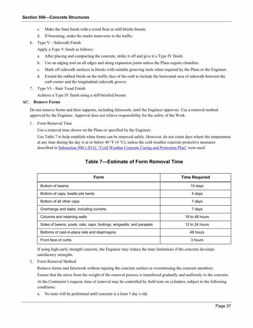
Section 500—Concrete Structures
Page 37
c. Make the final finish with a wood float or stiff-bristle broom.
d. If brooming, make the marks transverse to the traffic.
6. Type V—Sidewalk Finish
Apply a Type V finish as follows:
a. After placing and compacting the concrete, strike it off and give it a Type IV finish.
b. Use an edging tool on all edges and along expansion joints unless the Plans require chamfers.
c. Mark off sidewalk surfaces in blocks with suitable grooving tools when required by the Plans or the Engineer.
d. Extend the rubbed finish on the traffic face of the curb to include the horizontal area of sidewalk between the
curb corner and the longitudinal sidewalk groove.
7. Type VI—Stair Tread Finish
Achieve a Type IV finish using a stiff-bristled broom.
AC. Remove Forms
Do not remove forms and their supports, including falsework, until the Engineer approves. Use a removal method
approved by the Engineer. Approval does not relieve responsibility for the safety of the Work.
1. Form Removal Time
Use a removal time shown on the Plans or specified by the Engineer.
Use Table 7 to help establish when forms can be removed safely. However, do not count days where the temperature
at any time during the day is at or below 40 °F (4 °C), unless the cold weather concrete protective measures
described in Subsection 500.1.03.G, ―Cold Weather Concrete Curing and Protection Plan‖ were used.
Table 7—Estimate of Form Removal Time
Form Time Required
Bottom of beams 10 days
Bottom of caps, trestle pile bents 4 days
Bottom of all other caps 7 days
Overhangs and slabs, including culverts 7 days
Columns and retaining walls 18 to 48 hours
Sides of beams, posts, rails, caps, footings, wingwalls, and parapets 12 to 24 hours
Bottoms of cast-in-place rails and diaphragms 48 hours
Front face of curbs 3 hours
If using high-early strength concrete, the Engineer may reduce the time limitations if the concrete develops
satisfactory strengths.
2. Form Removal Method
Remove forms and falsework without injuring the concrete surface or overstressing the concrete members.
Ensure that the stress from the weight of the removal process is transferred gradually and uniformly to the concrete.
At the Contractor’s request, time of removal may be controlled by field tests on cylinders, subject to the following
conditions:
a. No tests will be performed until concrete is a least 3 day s old.

Section 500—Concrete Structures
Page 38
b. Required strengths will be shown on the Plans, as noted elsewhere in these Specifications, or as determined by
the Engineer.
c. The Engineer may specify a minimum time in conjunction with minimum strength requirements.
d. Falsework and forms for culverts may be removed at such time as 75% of the concrete design strength is
achieved.
AD. Apply Protective Surface Treatment
When the Plans specify a protective surface treatment, apply a boiled linseed oil mixture of 75 percent boiled linseed oil
and 25 percent mineral spirits by volume to the concrete surfaces.
Use linseed oil that meets the requirements of ASTM D 260, Type I or Type II. Use a quality commercial mineral spirit
that passes infrared spectroscopic analysis to the satisfaction of the laboratory.
Unless otherwise noted on the Plans or the manufacturer’s recommendations, apply the mixture as a preservative seal
coat to the top surfaces of bridge decks, curbs, and sidewalks and to the inside vertical faces of curbs, parapets, and end
posts. Protect metal handrailing and metal handrail posts from treatment.
Apply the protective surface treatment as follows:
CAUTION: Because the linseed oil-petroleum spirits mixture has a low flash point and is readily flammable,
protect the mixture from fire, especially cigarettes and sparks. Prohibit traffic from the treated area until the
Engineer determines the concrete has regained its dry appearance.
1. Do not place the protective surface treatment until concrete work, including final rubbing, is completed and
expansion joint sealing compound is placed.
2. Do not apply the treatment until the concrete is at least 14 days old.
3. Unless otherwise permitted by the Engineer, apply the treatment when the temperature of the concrete and air is at
least 50 °F (10 °C).
4. Apply in time to allow the treatment to dry thoroughly before allowing traffic, including haul traffic, on the
structure.
If the structure meets the following exceptions, apply the treatment after using the structure for hauling.
Temperature limitations prohibit application.
The Engineer will send a written notification to the Contractor (or Bridge Contractor) if temperature
requirements prohibit application.
The structure is absolutely required for hauling to complete a Contract.
Request a written approval from the Engineer if hauling across a structure before the treatment is placed.
5. If applying the treatment after using the structure for hauling, thoroughly clean the surfaces to be treated to allow the
treatment to penetrate completely.
6. If there are separate bridge and roadway Contracts, have the roadway Contractor clean the surfaces immediately
upon request by the Engineer.
7. Prepare the surface for the treatment as follows:
a. Clean off oil, grime, and loose particles that prevent the mixture from penetrating.
b. Ensure that the concrete surfaces have at least 48 hours to dry after rainfall or wet cleaning operations.
c. Immediately before applying the treatment, direct an air blast over the surfaces to remove dust.
d. Mask the exposed plates of joints.
8. Apply the mixture by hand or by spraying in one application at the rate of 1 gal (1 L) of mixture per 37.5 yd² (8.5
m²).

Section 500—Concrete Structures
Page 39
a. Thoroughly clean the inside of spraying equipment before putting the surface treatment in.
b. Keep spray nozzles within 18 in (600 mm) of the concrete unless otherwise directed by the Engineer, Plans, or
manufacturer.
AE. Apply Graffiti-Proof Coating
When the Plans specify a graffiti-proof coating, apply the coating system to concrete surfaces or over special surface
coatings. Use material that complies with Section 838.
Apply the coating as follows:
1. Clean loose particles, dirt, grease, oil, and other foreign particles off the surface.
2. Apply the coating according to the manufacturer’s recommendations for:
Weather conditions
Material preparation
Coating application
Number of coats
AF. Expose New Concrete to Loads
Prohibit dead or live loads during or after construction except as described in this section. If using high early strength
concrete, the Engineer may reduce time limitations if the concrete develops adequate strength.
1. Dead Loads on the Substructure
After pouring footings, do not begin work on columns or piers for at least 12 hours.
After pouring columns, do not begin cap construction for at least 24 hours.
Do not place beams on caps or place falsework and forming for concrete T-Beam construction before the cap
concrete reaches a minimum strength of 2,500 psi (17 MPa).
2. Dead Loads on the Superstructure
If necessary, stockpile construction materials on decks within a complete unit (a simple span or continuous or
cantilever unit) if the following conditions exist:
The deck concrete of the complete unit reaches its 28-day cylinder strength.
The deck concrete is at least 10 days old.
The curbs are at least 5 days old.
The Engineer must approve the location, height, and spread of the loads.
On composite-design bridges (those that have prestressed concrete beams or steel beams with shear connectors), do
not pour curbs, parapets, or sidewalks until the deck concrete reaches a minimum strength of 1,500 psi (10 MPa) or
is at least 3 days old.
3. Dead Loads on Concrete Box Culverts
Do not backfill any section of a concrete box culvert until the last concrete placed in that section is at least 14 days
old, unless early cylinder breaks indicate otherwise.
If early cylinder breaks indicate that design strength has been achieved, backfill sections of culverts when the
concrete placed last is at least 7 days old.
4. Live Loads—Pouring Equipment
Do not allow power-operated concrete buggies to cross a deck until the concrete reaches a minimum strength of
1,500 psi (10 MPa) or is at least 3 days old.
Allow hand-operated buggies to cross after the concrete is 24 hours old.
5. Live Loads—Mixing and Lifting Equipment

Section 500—Concrete Structures
Page 40
Do not place mixers on a deck in a complete unit (a simple span or continuous or cantilever unit) until the deck
concrete of the complete unit reaches its 28-day cylinder strength and is at least 10 days old.
When deck concrete reaches its 28-day cylinder strength and is at least 10 days old, allow mixer trucks on the unit
during the curb concrete pour only if the pour is completed within 45 minutes of being started.
Do not allow any equipment on the unit for 5 days after curb pours.
The Engineer may allow concrete placement procedures that use heavy lifting equipment on the decks if the
following conditions exist:
The deck concrete reaches its 28-day cylinder strength.
The deck concrete is at least 14 days old.
The curbs on the deck are at least 10 days old.
6. Live Loads—Hauling over Bridges
Use a new bridge for hauling only if no other practical haul routes are available and only if the Engineer permits it.
a. Govern hauling by the restrictions and requirements listed in Table 8. If any of the restrictions and requirements
are violated, the Engineer will limit loads to the following:
Single 32,000 lb (14 515 kg) axle when the bridge design loading is HS 20-44 and/or Military Loading
Single 24,000 lb (10 886 kg) axle when the bridge design loading is HS 15-44 or H 15-44
Table 8—Weight Limits for Hauling on New Bridges
Axle Criteria
Bridge Design Loading
HS 20-44 and/or Military Loading HS 15-44 or H 15-44
Maximum Axle Load Per Axle 60,000 lbs (27 216 kg) 44,000 lbs (19 958 kg)
Maximum Axle Load on Dual Axles
Per Axle
45,000 lbs (20 412 kg) 33,000 lbs (14 969 kg)
Maximum Total Load 100,000 lbs (45 360 kg) 73,000 lbs (33 113 kg)
b. Ensure that bridge concrete, including curbs, parapets, barriers and sidewalks, is at least 14 days old and has a
minimum compressive strength of 3,000 psi (20 MPa).
c. Apply the linseed oil special protective treatment, if required see (Subsection 500.3.05.AD, ―Apply Protective
Surface Treatment‖).
d. After applying the protective treatment (if required), apply water-repellent silicone materials to the handrail,
handrail posts, end posts, and curb faces before hauling begins.
e. Do not allow more than one vehicle at a time on a simple or multiple-span unit.
f. Ensure that vehicle speeds, loaded or unloaded, do not exceed 5 miles/hr (8 km/hr) when the following loads
occur:
Bridges designed for HS 20-44 and/or Military Loading:
—Loads on single axles exceed 32,000 lbs (14 515 kg)
—Loads on each dual axle exceed 24,000 lbs (10 886 kg)
Bridges designed for HS 15-44 or H 15-44 loading:
—Loads on single axles exceed 24,000 lbs (10 886 kg)

Section 500—Concrete Structures
Page 41
—Loads on each dual axle exceed 16,000 lbs (7257 kg)
When axle loads do not exceed these loads, ensure that vehicle speeds are 15 mph (24 kph) or less.
g. Place temporary guides on beams so wheels will track directly.
h. Keep earth approaches smooth and level with the bridge floor or approach slab to minimize impact.
Stabilize sandy and other unstable soils (at no expense to the Department) with crushed stone or other suitable
material for at least 10 ft (3 m) from the end of the bridge or approach slab.
i. Protect the ends of bridges or approach slabs with a timber strip at least 4 in (100 mm) wide, cut to rest on either
the paving rest of the bridge end or the pavement subgrade at the end of the approach slab. Keep the strip in
place for protection during incidental hauling. Remove it before constructing the adjacent pavement.
Keep the top of each timber strip flush with the top of the concrete surface. Fit the strip tightly against the end
of the bridge or approach slab. If the timber strip is displaced, stop hauling until the strip is reset or replaced.
j. Clean spills off the bridge floor.
AG. Complete Corrective Work
After the Department gives the deck surface a Ride Quality Test described in Subsection 500.3.06.E, ―Ride Quality Test,‖ complete corrective work at no cost to the Department and before doing the final surface texturing.
Complete corrective work as follows:
1. Plane the deck according to Section 431.
2. Limit concrete removal by planing so that the final bar cover is not less than the Plan cover minus 1/2 in (13 mm).
3. If the final bar cover limits cannot be met, perform the corrective work as directed by the Engineer.
4. Ensure that the final riding surface complies with this Specification and the requirements for a grooved finish.
5. If necessary, use a bump grinder to correct bumps with a profile base line of 5 ft (1.5 m) or less.
6. Have planed decks retested as described in Subsection 500.3.06.E, ―Ride Quality Test,‖ to ensure that the ride
quality meets the requirements of this Specification.
AH. Plane the Deck
Schedule profilograph testing. Give at least 5 days’ advance notice. Ensure that the area to be tested is clean and clear of
obstructions.
When possible, delay expansion joint installation and temporarily bridge the joint to operate profilograph and planing
equipment across the joint.
Planing responsibilities are shown in Table 9:
Table 9—Planning Responsibilities
Area Planed Person Responsible
Bridge decks Bridge Contractor
Approach slabs constructed under the bridge Contract Bridge Contractor
Approach slabs constructed under the roadway Contract Roadway Contractor
AI. Perform Retaining Wall Incidentals
Retaining wall incidentals are as follows:
1. Drainage

Section 500—Concrete Structures
Page 42
Unless otherwise shown on the Plans or in the Special Provisions, ensure that drainage for retaining walls is either
Alternate A or Alternate B on Georgia Standards 4948 and 9031-L.
Ensure that the Number 10 concrete sand complies with Subsection 801.2.02, ―Fine Aggregate for Portland cement
Concrete of All Types and for Mortar‖ and has a permeability coefficient of at least 100 ft (30 m) per day.
The Engineer may waive the grading requirement for Number 10 concrete sand if the permeability coefficient of the
material does not exceed 500 ft (150 m) per day.
Omit the drainage blanket and stone for retaining walls only when the height does not exceed 6 ft (1.8 m).
When the Plans specify different drainage details, furnish, place, or build the various items according to the Plan
requirements.
2. Waterproofing and Dampproofing
When waterproofing and dampproofing are specified in the Plans, comply with the requirements of Sections 530 and
531.
AJ. Place Utility Installation Hardware
When the Plans require placing utility installation hardware, the utility company involved will furnish the items.
Place the items as directed on the Plans or Shop Drawings. All other work, including painting as required, is the utility
company’s responsibility.
AK. Widen Bases and Pavement
When using narrow sections of Portland cement concrete to widen existing bases or bases and pavements, use Class B
concrete as shown on the Plans or as directed by the Engineer.
AL. Open the Structure to Traffic
Open a structure to traffic other than haul traffic after all concrete in the decks, parapets, or curbs (sidewalks) reaches its
28-day cylinder strength and is at least 14 days old.
500.3.06 Quality Acceptance
A. Strength Requirement Tests
When job site test specimens fail to meet the strength requirements in the Table 1—Concrete Mix Table , determine the
Final Acceptance or rejection of concrete in place by coring or non-destructive testing.
At the Contractor’s request, the Department will determine the removal time for forms by conducting field tests on
cylinders.
Tests are subject to the following:
1. Tests will be performed when the concrete is at least three days old.
2. The Plans will show the required strengths.
3. At the Contractor’s request, the Engineer may specify a minimum time with minimum strength requirements.
B. Honeycombed Area Check
If there are honeycombed areas that extend beyond the reinforcement steel, the Engineer may reject the entire pour with
the honeycombed area.
C. Bridge Deck Slab Concrete Inspection
The Engineer will carefully observe the construction methods used during all phases of the bridge deck slab construction.
These phases include the following:
Metal form installation

Section 500—Concrete Structures
Page 43
Reinforcement location and fastening
Concrete item composition
Mixing procedures
Concrete placement and vibration
Bridge deck finishing
Provide the needed facilities for the Engineer to safely and conveniently inspect the concrete.
The concrete inspection procedure is as follows:
1. After the deck concrete has been in place for at least two days, the Engineer will sound a hammer on at least two
areas of the deck for each slab pour. This test checks for concrete soundness and form bonding.
The two areas will encompass at least 10 percent of the total area of the deck pour.
2. The Engineer will sound other areas of the deck randomly.
3. If the Engineer doubts the soundness of an area, or if the Engineer decides that the concrete placement procedures
used call for an inspection of the underside of the deck, remove at least one section of the forms for each span in the
Contract.
4. Remove the form section after the pour is strong enough and when the Engineer desires to provide visual evidence
that the concrete mix and the placement procedures are acceptable.
5. Remove another form section if the Engineer decides changes in the concrete mix or in the placement procedures
warrant additional inspection.
6. Where form sections are removed, do not necessarily replace the forms, but repair the adjacent metal forms and
supports neatly and securely.
7. When the form is removed, the Engineer will examine the concrete surfaces for cavities, honeycombing, and other
defects.
8. If the Engineer finds irregularities but determines that the irregularities do not justify rejection of the Work, repair
the concrete as the Engineer directs and give it an ordinary surface finish according to the Contract Specifications.
9. If the concrete where the form is removed is not acceptable, remove additional forms as necessary to inspect and
repair the slab.
10. Modify the construction methods as required by the Engineer to create satisfactory slab concrete.
11. Remove or repair all unsatisfactory concrete as the Engineer directs.
If the construction methods used and the inspection results indicate that the slabs have sound concrete, the Engineer
may moderate the amount of random sounding and form removal after a substantial amount of slab has been
constructed and inspected.
D. Bridge Deck Surface Check
After the final strike-off of the concrete and as close behind the final strike-off as possible, the Engineer will check the
surface with a 10 ft (3 m) straightedge.
Attach the straightedge to a broom-type handle for easy control and use.
Bridges and approach slabs must meet a 1/8 inch in 10 ft (3 mm in 3 m) straightedge check made longitudinally and
transversely.
E. Ride Quality Test
After the bridge decks and approach slabs are completed, the Department will perform a Ride Quality Test using the
Rainhart Profilograph and a profile index value determined according to GDT 78.
The Department will conduct the test as follows:

Section 500—Concrete Structures
Page 44
1. Obtain Profile Index Values for bridge decks and approach slabs for:
State roads with four lanes or more
State roads with 2 lanes where the current traffic count is 2,000 vehicles per day or higher
Other roads designated on the Plans
Bridges and approach slabs must meet the straightedge check limits described in
Subsection 500.3.06.D, ―Bridge Deck Surface Check.‖
2. Obtain profiles in the wheel paths and in safety areas to within 6 ft (1.8 m) of barrier or curb lines.
3. Average the profile index values for bridge decks including the approach slabs for the left and right wheel path for
each lane.
The average value must not exceed 15 in/mile (235 mm/km) for each lane.
After the test is complete, correct individual bumps or depressions that exceed 2/10 in (5 mm) from the blanking band on
the profilograph trace.
The deck surface must then meet a 1/8 inch in 10 ft (3 mm in 3 m) straightedge check made transversely.
Correct bridge decks and approach slabs that do not pass the Ride Quality Test as described in
Subsection 500.3.05.AG, ―Complete Corrective Work.‖
500.3.07 Contractor Warranty and Maintenance
General Provisions 101 through 150.
500.4 Measurement
This work is measured for payment either per cubic yard (meter), per Lump Sum, or per linear foot (meter), whichever is
shown on the Plans.
Seal Concrete. The quantity of seal concrete to be measured for payment is calculated using the horizontal seal
dimensions specified on the Plans.
Grooving. Grooving on bridge decks and approach slabs, completed acceptably according to
Subsection 500.3.05.T, ―Place Bridge Deck Concrete,‖ step 9.c, will be measured and paid for by the square yard
(meter). Payment is full compensation for furnishing the necessary equipment and performing the Work.
Class B Concrete. Class B concrete used for base and pavement widening will be measured and paid for by the
cubic yard (meter) complete in place and accepted.
500.4.01 Limits
A. Measurement for Separate Payment
There will be no separate measurement and payment for the following:
1. On permanent steel bridge deck forms for concrete deck slabs:
Extra reinforcing
Extra concrete
Other costs incurred because of the requirements of this Specification
All costs are included in the Lump Sum prices bid for superstructure concrete and superstructure reinforcement.
B. Payment per Cubic Yard (Meter)
Measurement limits on payment per cubic yard (meter) are:
1. Bridges, Concrete Culverts, Headwalls, and Retaining Walls

Section 500—Concrete Structures
Page 45
The quantity of concrete measured for payment is the algebraic summation of the Base Pay Quantity and authorized
quantity changes.
If additional quantities are necessary because of any of the following, these quantities are measured separately for
payment:
Rocks were removed carefully but additional quantities are needed because footing depth and keyway
dimension are irregular from unanticipated rock removal.
Voids or crevices exist within the spread footing area.
The Engineer authorized filling trenches cut in rock outside footing areas to ease dewatering.
These additional quantities will be paid as filler concrete per cubic yard (meter).
2. Seals
When the Plans do not require a seal but a seal becomes necessary, or when the Plans do not show seal dimensions,
the maximum pay dimensions in each direction will be the Plan dimension of the structural footing plus 3 ft (1 m),
with 18 in (600 mm) on each side.
If the Contractor uses lesser dimensions, measurement is based on the lesser dimensions. Concrete placed beyond
the maximum pay limits are not measured.
C. Payment per Lump Sum
For Lump Sum payment, determine the quantities required before submitting the bid.
The concrete quantity must conform to the Plan dimensions. Measurement is made as a unit, complete in place, and
includes the following:
Diaphragms
Sidewalks
Concrete parapets
Measurement does not include concrete in the following items that will be paid for separately:
Concrete handrailing
Barriers
Prestressed bridge members.
Payment for parapets placed by slip-form method is included in the Lump Sum price bid for superstructure concrete.
Unless otherwise shown on the Plans, the cost of steel joints and metal bearing assemblies used in structures where there
is no structural steel Pay Item are included in the Contract Price for superstructure concrete.
D. Retaining Wall Incidentals
Retaining wall incidentals will be measured for payment as follows:
1. Drainage Systems
Drainage items required by Special Plans are measured for payment by the unit specified on the Plans only when
they are set up as specific Pay Items and are paid for separately. Otherwise, their costs are included in the Contract
Price for concrete.
Payment is full compensation for the costs of excavation and backfill necessary to place the drainage items required
by Special Plans.
The following are not measured for separate payment. Costs are included in the Contract Price for concrete.
Sand blankets
Crushed or broken stone

Section 500—Concrete Structures
Page 46
Weep holes
2. Miscellaneous
The following are not measured for separate payment. Costs are included in the Contract Price for concrete.
Expansion material
Rubber or polyvinyl plastic water stops
E. Utility Installation Hardware
The cost of placing utility hardware items is included in the Contract Price for the class of concrete the items are placed
in.
500.5 Payment
This Work will be paid for at the Contract Price per cubic yard (meter), per Lump Sum, or per linear foot (meter), each
complete in place and accepted.
Payment is full compensation for all things, including incidentals, and direct and indirect costs, to complete the Work.
Payment will be made under:
Item No. Item Payment
500 Superstructure concrete class_____, Bridge no._____ Per lump sum
500 Concrete handrailing (designation) Per linear foot (meter)
500 Class_____concrete Per cubic yard (meter)
500 Class_____concrete, high-early strength Per cubic yard (meter)
500 Seal concrete Per cubic yard (meter)
500 Class B concrete base or pavement widening Per cubic yard (meter)
500 Class_____concrete including reinforcement steel Per cubic yard (meter)
500 Class A concrete—filler Per cubic yard (meter)
500 Class_____concrete—retaining wall Per cubic yard (meter)
500 Grooved concrete Per square yard (meter)
500 Concrete barrier Per linear foot (meter)
500.5.01 Adjustments
A. Contractor Costs
Assume the following costs:
1. Costs related to rejected concrete and removing rejected concrete
2. Costs of forming an approved construction joint, removing a partial pour, or completing other remedial measures
requested by the Engineer unless the fault lies solely with the Department
3. Costs of repairing, removing, and replacing falsework as directed by the Engineer
4. Costs of repairing, removing, or replacing forms
5. Costs of air-blown mortar to repair honeycombed areas, if required by the Engineer
6. Costs of using a higher class of concrete to widen existing bases or bases and pavements
Section 500—Concrete Structures
Page 47
B. Profilograph Testing
The Department will conduct profilograph testing of bridge decks and approach slabs only twice per bridge at no cost to
the Contractor.
The Department will conduct additional profilograph testing at the cost of $500 per test.
C. Plastic Shrinkage Crack Repair
The Engineer will determine how to repair cracks caused by plastic shrinking. Repair cracks at no cost to the
Department.
D. Plan Quantities
For all bridges (except seal concrete), concrete culverts, headwalls, and retaining walls, the quantities shown on the
Contract Plans, including Standard Plans, will be considered the Base Pay Quantity.
For seal concrete, the Plan quantities are approximate and are for estimating purposes only. The quantities will not be
considered as Base Pay Quantities.
Calculated additions or deductions will be applied to the Base Pay Quantity when the Engineer makes authorized
changes. Changes include, but are not limited to, authorized changes in the following:
Footing dimensions
Lengthening or shortening of concrete culverts
Correcting Plan Quantities
Dimension errors
Multi-barrel culvert wall thicknesses
Lengthening or shortening bridge columns
Raising or lowering foundations
Calculations of the Base Pay Quantity and any changes will be made as follows:
1. No deductions will be made for the volume of concrete used by scorings, panels, and chamfers if the individual
areas are less than 1 in² (625 mm²).
The volume of concrete in fillets of the same area will be neglected.
2. The volume of structural steel and of steel and concrete piling encased in concrete will be deducted.
3. The volume of timber piling encased in concrete will be deducted on the basis of 0.8 ft³/linear foot (0.07 m³/linear
meter) of pile.
4. No deduction will be made for the volume of concrete displaced by the following:
Steel reinforcement
Shear connectors
Floor drains (unless they are paid for as separate Pay Items)
Incidentals such as expansion material
Joint sealing compound
Utility thimbles and hangers
E. Filler Concrete
Filler concrete, measured as described in Subsection 500.4.01.B.1, ―Bridges, Concrete Culverts, Headwalls, and Retaining Walls,‖ will be paid at 40 percent of the Contract Price per cubic meter for Class A Concrete or Class AA
Concrete.

Section 500—Concrete Structures
Page 48
F. Seal Concrete
If there is no Contract Price for seal concrete, payment will be per cubic yard (meter), measured as described in
Subsection 500.4.01.B.2, ―Seals,‖ and will be paid at 60 percent of the Contract Price per cubic yard (meter) for Class A
concrete.
G. Lump Sum Payment Adjustments
Adjust the payment as follows:
1. Authorized Change Adjustments
When authorized changes are made as described in Subsection 500.5.01.D, ―Plan Quantities,‖ the lump sum
payment may be adjusted on a pro rata basis or according to Section 104 and as determined by the Engineer.
The Plans show tabulated quantities as a service. This does not relieve any responsibility to conform to Plan details.
2. Optional Plan Feature Adjustments
If exercising an optional Plan feature, the Base Pay Quantity will not be changed if it is the only quantity change
involved.
However, if other changes are necessary, the quantity change resulting from the optional feature will be considered
in the necessary quantity adjustments.
3. Falsework for Post-Tensioned Box Girder Bridge Adjustments
When the falsework is completed for post-tensioned box girder bridges, 20 percent of the Lump Sum superstructure
concrete price will be paid.
Additional payments made as the concrete is placed must be adjusted for the payment for falsework. In other words,
payment for concrete placed will be based on 80 percent of the superstructure bid price.
4. When Metal Deck Forms are used and have been placed, payment in the amount of 5% of the Lump Sum
Superstructure Concrete price will be made. For Post-Tensioned Box Girder Bridges, this percentage (5%) will
apply to that part of the superstructure concrete in the top slab of the box only.