Section 4.7 –Interferograms
9
3/30/2018 1 Section 4.7 – Interferograms W 020 Defocus Defocus & Y-Tilt -2 m -1 m 0m 1 m 2 m Section 4.7 – Interferograms W 020 Spherical Aberration Spherical Aberration & Y-Tilt -2 m -1 m 0m 1 m 2 m
Transcript of Section 4.7 –Interferograms

3/30/2018
1
Section 4.7 – Interferograms
W020
Defocus
Defocus & Y-Tilt
-2 m -1 m 0m 1 m 2 m
Section 4.7 – Interferograms
W020
Spherical Aberration
Spherical Aberration & Y-Tilt
-2 m -1 m 0m 1 m 2 m

3/30/2018
2
Section 4.7 – Interferograms
W020
Astigmatism
Astigmatism & Y-Tilt
-2 m -1 m 0m 1 m 2 m
Section 4.7 – Interferograms
W020
Coma
Coma & Y-Tilt
-2 m -1 m 0m 1 m 2 m

3/30/2018
3
Relative Intensities1:1 2:1 4:1
8:1 16:1 32:1
Aliasing
Sampling a low frequency pattern accurately approximates the curve, butwhen high frequency patterns are sampled, the pattern is reduced to a lowerfrequency shape.

3/30/2018
4
Aliasing
Hubble Telescope

3/30/2018
5
Hubble Telescope
Ritchey-Chretien telescope with 2.4 m primary mirror.
Aberrations
Before Repairs After Repairs

3/30/2018
6
Reflective Null Corrector
Reflective null corrector converts incident spherical wave into a suitable shape to retro-reflect from the primary mirror
Reflective Null Alignment
Metal rods with rounded ends were used to set the spacing between the mirrors and the field lens. An interferometer is used to precisely locate the end of the rod through retro-reflection.

3/30/2018
7
Rod CapsCaps were placed on the ends of the rods to help make sure the rod was centered. The rod was visible through a small hole in the cap. The end of the cap had an anti-reflective coating applied to it.
Some of the anti-reflective coating in the neighbor of the hole had broken away.
Misalignment of Field Lens
Unfortunately, when locating the end of the rod for position the field lens, the operator got a retro-reflection off the field cap instead of the rod. This ultimately led to a 1.3 mm displacement in the axial position of the field lens and an incorrect amount of spherical aberration in the reflective null corrector. This spherical aberration in turn was polished into the primary mirror.

3/30/2018
8
Failure Report
These errors were identified by a team of independent scientists. Ultimately, corrective optics were developed and deployed based on the failure report and the image quality of the repaired telescope has led to unprecedented images of the universe.
Four‐Step Algorithm
Phase Shift
0 /2 /2
3/30/2018
9
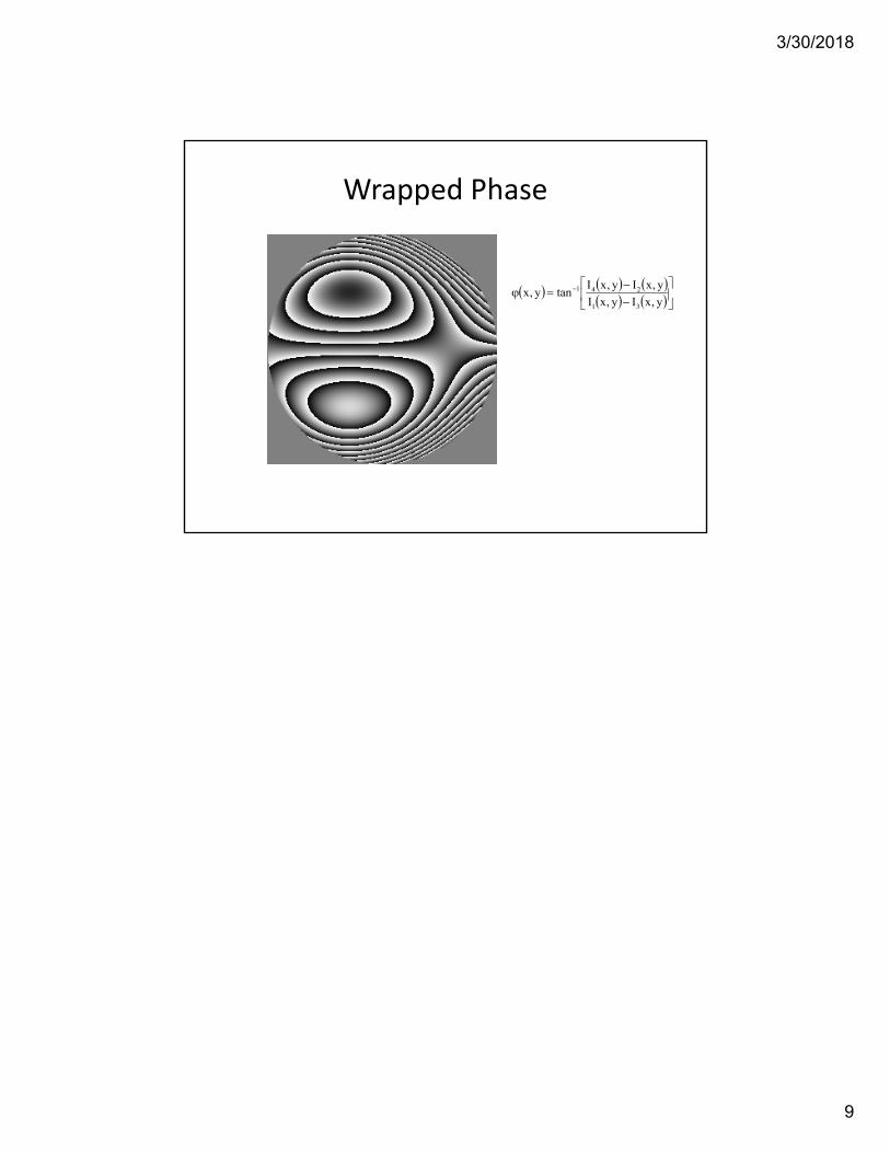
Wrapped Phase
y,xIy,xI
y,xIy,xItany,x
31
241


![[PPT]Chapter #4, Section 4.7 - 4.8 - University of Mary …mars.umhb.edu/~wgt/engr2320/Hibbeler_12th/ch04/Lecture... · Web viewTitle Chapter #4, Section 4.7 - 4.8 Author Mehta &](https://static.fdocuments.in/doc/165x107/5aebca677f8b9ac3618fa525/pptchapter-4-section-47-48-university-of-mary-marsumhbeduwgtengr2320hibbeler12thch04lectureweb.jpg)