SECTION 40 ENGINE AND MOTOR CONTROLS
60
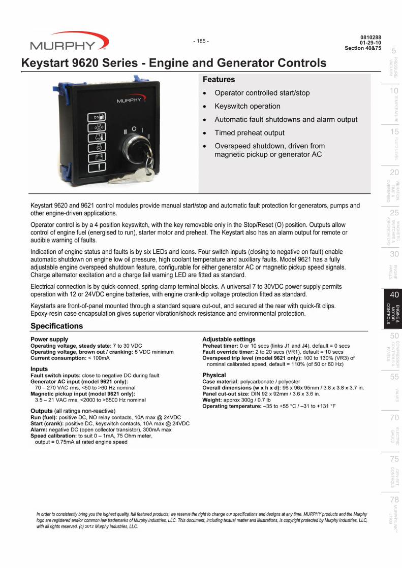
SECTION 40 ENGINE AND MOTOR CONTROLS Engine and Generator Controls 0810288 Keystart 9620 Series – Engine and Generator Controls . . . . . . . . . . . . . . . . . . . . . . . . . . . . . . . . . . . . . . . . 185 0810330 CANstart 9630 Series – Engine and Generator Controls . . . . . . . . . . . . . . . . . . . . . . . . . . . . . . . . . . . . . . . . 187 Auto Start Controllers 94012 Automatic Engine Controller ASM150 . . . . . . . . . . . . . . . . . . . . . . . . . . . . . . . . . . . . . . . . . . . . . . . . . . . . . . 189 03021 ASM170 Auto Start Module . . . . . . . . . . . . . . . . . . . . . . . . . . . . . . . . . . . . . . . . . . . . . . . . . . . . . . . . . . . . . . 191 97079 MURPHYMATIC® Engine Micro-Controller A91 Series . . . . . . . . . . . . . . . . . . . . . . . . . . . . . . . . . . . . . . . . 193 05195 Auto-Start/Stop Controller – Cascade . . . . . . . . . . . . . . . . . . . . . . . . . . . . . . . . . . . . . . . . . . . . . . . . . . . . . . 195 Digital Engine Controller 1010554 EMS PRO Engine Monitoring Control System . . . . . . . . . . . . . . . . . . . . . . . . . . . . . . . . . . . . . . . . . . . . . . . . 197 1110770 EMS PRO LITE - Engine Monitoring System Controller . . . . . . . . . . . . . . . . . . . . . . . . . . . . . . . . . . . . . . . . . 199 0910364 EMS467 Monitoring System . . . . . . . . . . . . . . . . . . . . . . . . . . . . . . . . . . . . . . . . . . . . . . . . . . . . . . . . . . . . . 201 92199 Electronic Monitoring Systems – EMS447 / EMS448 Controllers . . . . . . . . . . . . . . . . . . . . . . . . . . . . . . . . . 203 95122 Electronic Monitoring System/Controller – Model EMS547 . . . . . . . . . . . . . . . . . . . . . . . . . . . . . . . . . . . . . 205 Rack Pullers 00092 Pull/Push DC Solenoids for Diesel Engines – RP2900 Series . . . . . . . . . . . . . . . . . . . . . . . . . . . . . . . . . . . . 207 95028 Rack Puller for Diesel Engines – Model RP75 . . . . . . . . . . . . . . . . . . . . . . . . . . . . . . . . . . . . . . . . . . . . . . . 211 Throttle Controller 04052 MURPHYMATIC® Engine Throttle Controller – Model AT03069 . . . . . . . . . . . . . . . . . . . . . . . . . . . . . . . . . 213 Clutch Controller 01035 Electric Motor Driven Clutch Operator for Engine Automation Systems – Model CO3 . . . . . . . . . . . . . . . . . 215 Electric Motor Controllers 0910462 Transformer Relay Assemblies TR Series by MURPHYMATIC® . . . . . . . . . . . . . . . . . . . . . . . . . . . . . . . . . 217 Murphy Power Ignition Controls 0910474 MPI-8/16/32 Ignition Controllers . . . . . . . . . . . . . . . . . . . . . . . . . . . . . . . . . . . . . . . . . . . . . . . . . . . . . . . . . . . 221 0910517 MPI Ignition Control Systems (Murphy Power Ignition) – MPI 601 Series CD Ignition . . . . . . . . . . . . . . . . . 223 0910515 MPI Detonation Sensing Interface System – Model DSI . . . . . . . . . . . . . . . . . . . . . . . . . . . . . . . . . . . . . . . . 225 0910514 Power Supply (Murphy Power Ignition) – MPI Brushless Alternators . . . . . . . . . . . . . . . . . . . . . . . . . . . . . . 227 0910513 MPI Ignition Control Systems (Murphy Power Ignition) – MPI Ignition Coils . . . . . . . . . . . . . . . . . . . . . . . . . 229 Air-Fuel Ratio Controls - Compliance Controls 0910476 AFR-1R – Rich Burn Air-Fuel Ratio Controller . . . . . . . . . . . . . . . . . . . . . . . . . . . . . . . . . . . . . . . . . . . . . . . . 231 0910477 AFR-9R – Multipoint Air-Fuel Ratio Controller . . . . . . . . . . . . . . . . . . . . . . . . . . . . . . . . . . . . . . . . . . . . . . . . 233 0910475 AFR-64R – Rich-Burn Air-Fuel Control System . . . . . . . . . . . . . . . . . . . . . . . . . . . . . . . . . . . . . . . . . . . . . . . 235 0910491 AFR-64L – Lean-Burn Air-Fuel Control System . . . . . . . . . . . . . . . . . . . . . . . . . . . . . . . . . . . . . . . . . . . . . . . 237 0910478 AFR-FI – Air-Fuel Ratio Controller for Fuel Injected Engines . . . . . . . . . . . . . . . . . . . . . . . . . . . . . . . . . . . . 239 1010670 EICS – Engine Integrated Control System . . . . . . . . . . . . . . . . . . . . . . . . . . . . . . . . . . . . . . . . . . . . . . . . . . . 241
Transcript of SECTION 40 ENGINE AND MOTOR CONTROLS
SECTION 40 ENGINE AND MOTOR CONTROLS
Engine and Generator Controls0810288 Keystart 9620 Series – Engine and Generator Controls . . . . . . . . . . . . . . . . . . . . . . . . . . . . . . . . . . . . . . . . 185
0810330 CANstart 9630 Series – Engine and Generator Controls . . . . . . . . . . . . . . . . . . . . . . . . . . . . . . . . . . . . . . . . 187
Auto Start Controllers94012 Automatic Engine Controller ASM150 . . . . . . . . . . . . . . . . . . . . . . . . . . . . . . . . . . . . . . . . . . . . . . . . . . . . . . 189
03021 ASM170 Auto Start Module . . . . . . . . . . . . . . . . . . . . . . . . . . . . . . . . . . . . . . . . . . . . . . . . . . . . . . . . . . . . . . 191
97079 MURPHYMATIC® Engine Micro-Controller A91 Series . . . . . . . . . . . . . . . . . . . . . . . . . . . . . . . . . . . . . . . . 193
05195 Auto-Start/Stop Controller – Cascade . . . . . . . . . . . . . . . . . . . . . . . . . . . . . . . . . . . . . . . . . . . . . . . . . . . . . . 195
Digital Engine Controller1010554 EMS PRO Engine Monitoring Control System . . . . . . . . . . . . . . . . . . . . . . . . . . . . . . . . . . . . . . . . . . . . . . . . 197
1110770 EMS PRO LITE - Engine Monitoring System Controller . . . . . . . . . . . . . . . . . . . . . . . . . . . . . . . . . . . . . . . . . 199
0910364 EMS467 Monitoring System . . . . . . . . . . . . . . . . . . . . . . . . . . . . . . . . . . . . . . . . . . . . . . . . . . . . . . . . . . . . . 201
92199 Electronic Monitoring Systems – EMS447 / EMS448 Controllers . . . . . . . . . . . . . . . . . . . . . . . . . . . . . . . . . 203
95122 Electronic Monitoring System/Controller – Model EMS547 . . . . . . . . . . . . . . . . . . . . . . . . . . . . . . . . . . . . . 205
Rack Pullers00092 Pull/Push DC Solenoids for Diesel Engines – RP2900 Series . . . . . . . . . . . . . . . . . . . . . . . . . . . . . . . . . . . . 207
95028 Rack Puller for Diesel Engines – Model RP75 . . . . . . . . . . . . . . . . . . . . . . . . . . . . . . . . . . . . . . . . . . . . . . . 211
Throttle Controller04052 MURPHYMATIC® Engine Throttle Controller – Model AT03069 . . . . . . . . . . . . . . . . . . . . . . . . . . . . . . . . . 213
Clutch Controller01035 Electric Motor Driven Clutch Operator for Engine Automation Systems – Model CO3 . . . . . . . . . . . . . . . . . 215
Electric Motor Controllers0910462 Transformer Relay Assemblies TR Series by MURPHYMATIC® . . . . . . . . . . . . . . . . . . . . . . . . . . . . . . . . . 217
Murphy Power Ignition Controls0910474 MPI-8/16/32 Ignition Controllers . . . . . . . . . . . . . . . . . . . . . . . . . . . . . . . . . . . . . . . . . . . . . . . . . . . . . . . . . . . 221
0910517 MPI Ignition Control Systems (Murphy Power Ignition) – MPI 601 Series CD Ignition . . . . . . . . . . . . . . . . . 223
0910515 MPI Detonation Sensing Interface System – Model DSI . . . . . . . . . . . . . . . . . . . . . . . . . . . . . . . . . . . . . . . . 225
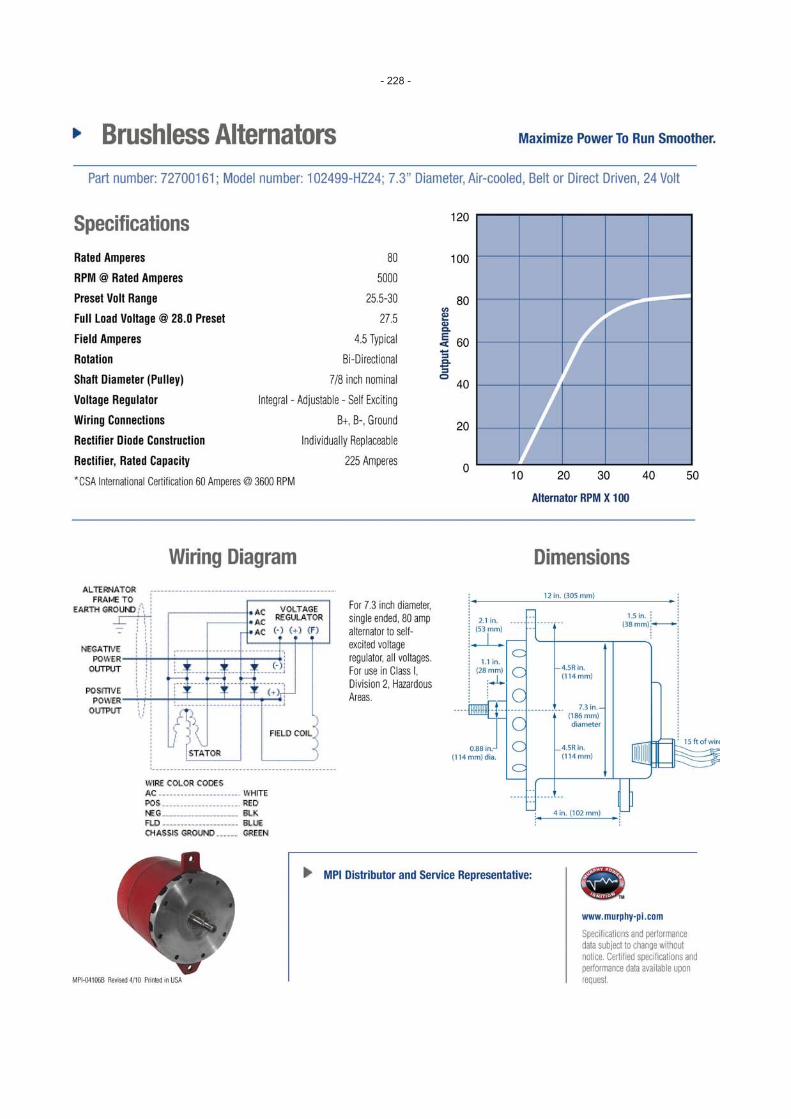
0910514 Power Supply (Murphy Power Ignition) – MPI Brushless Alternators . . . . . . . . . . . . . . . . . . . . . . . . . . . . . . 227
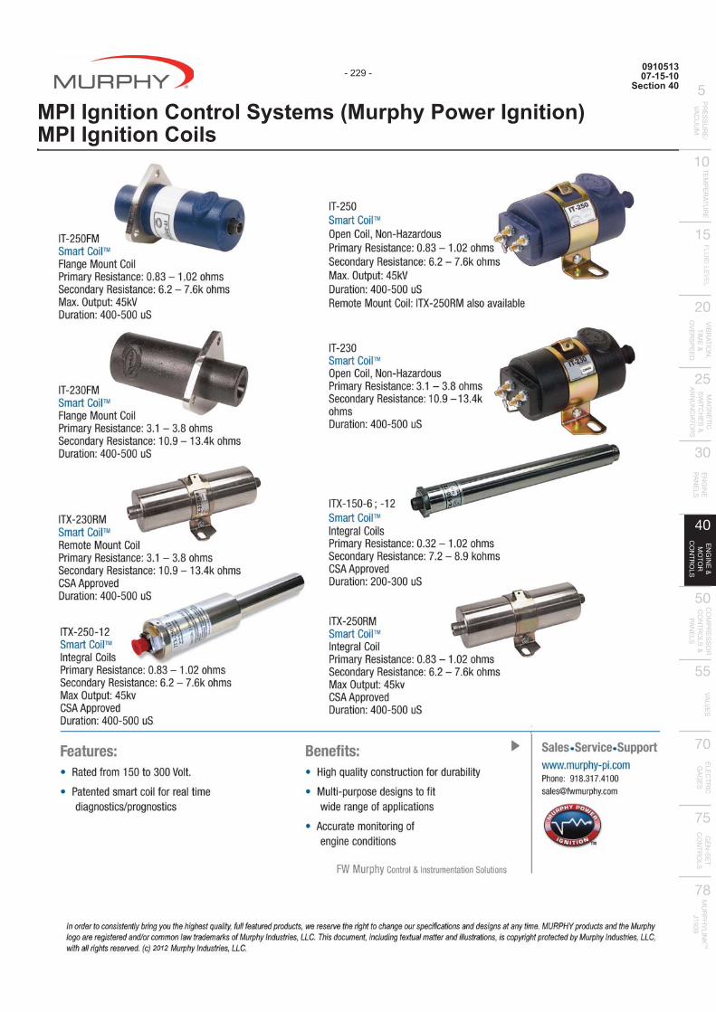
0910513 MPI Ignition Control Systems (Murphy Power Ignition) – MPI Ignition Coils . . . . . . . . . . . . . . . . . . . . . . . . . 229
Air-Fuel Ratio Controls - Compliance Controls0910476 AFR-1R – Rich Burn Air-Fuel Ratio Controller . . . . . . . . . . . . . . . . . . . . . . . . . . . . . . . . . . . . . . . . . . . . . . . . 231
0910477 AFR-9R – Multipoint Air-Fuel Ratio Controller . . . . . . . . . . . . . . . . . . . . . . . . . . . . . . . . . . . . . . . . . . . . . . . . 233
0910475 AFR-64R – Rich-Burn Air-Fuel Control System . . . . . . . . . . . . . . . . . . . . . . . . . . . . . . . . . . . . . . . . . . . . . . . 235
0910491 AFR-64L – Lean-Burn Air-Fuel Control System . . . . . . . . . . . . . . . . . . . . . . . . . . . . . . . . . . . . . . . . . . . . . . . 237
0910478 AFR-FI – Air-Fuel Ratio Controller for Fuel Injected Engines . . . . . . . . . . . . . . . . . . . . . . . . . . . . . . . . . . . . 239
1010670 EICS – Engine Integrated Control System . . . . . . . . . . . . . . . . . . . . . . . . . . . . . . . . . . . . . . . . . . . . . . . . . . . 241

TABLE OF CONTENTS
THIS PAGE INTENTIONALLY LEFT BLANK.
081028801-29-10
Section 40&75
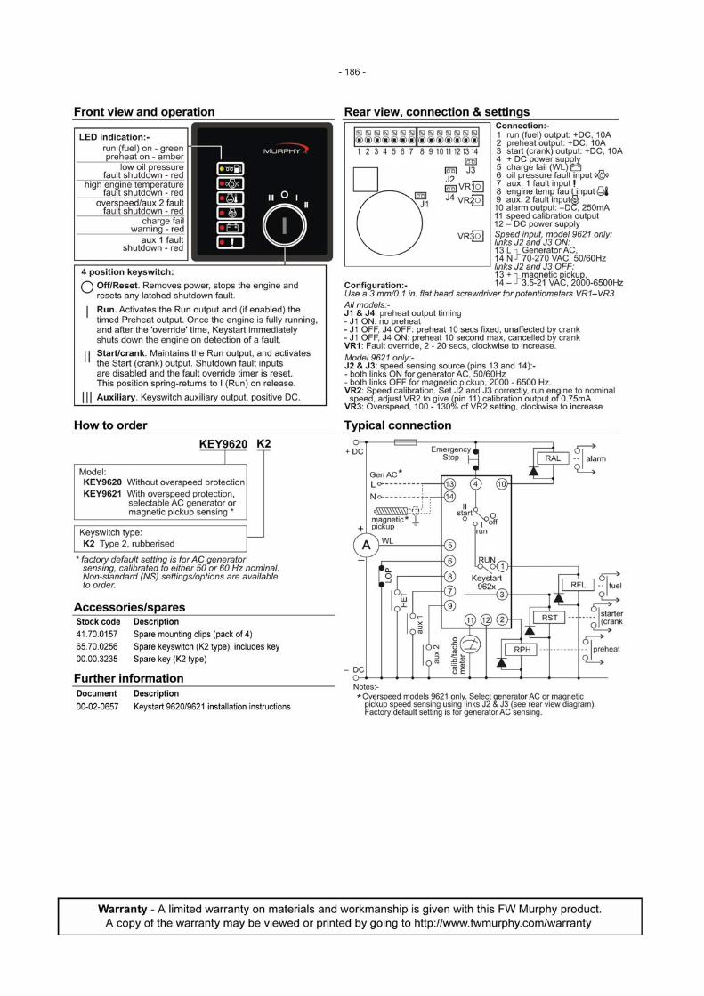
Keystart 9620 Series - Engine and Generator Controls
- 185 -
- 186 -

0810330 01-29-10
Section 40 & 75
CANstart™ 9630 SeriesEngine and Generator Controls
- 187 -

- 188 -
94012Revised 01-04
Section 40
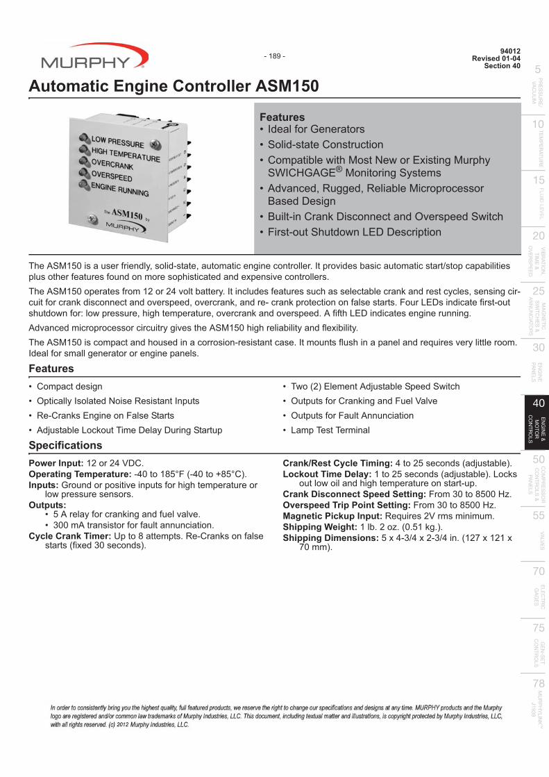
Automatic Engine Controller ASM150
The ASM150 is a user friendly, solid-state, automatic engine controller. It provides basic automatic start/stop capabilities plus other features found on more sophisticated and expensive controllers. The ASM150 operates from 12 or 24 volt battery. It includes features such as selectable crank and rest cycles, sensing cir-cuit for crank disconnect and overspeed, overcrank, and re- crank protection on false starts. Four LEDs indicate first-out shutdown for: low pressure, high temperature, overcrank and overspeed. A fifth LED indicates engine running. Advanced microprocessor circuitry gives the ASM150 high reliability and flexibility. The ASM150 is compact and housed in a corrosion-resistant case. It mounts flush in a panel and requires very little room. Ideal for small generator or engine panels.
Features � �������� ���� ��������� �������� ��� � ������ � �������� ����������� ���� � ���� �!��"�����#���$����$����������
� #%�&'*���������� �!��������%��+� ���� ;�����������������<��=�� ���� ;������������������ "���#� #�������
Specifications Power Input:>'��'?<$�@Operating Temperature:�?J�>QVW�&�?J�XQVW�*@Inputs: Ground or positive inputs for high temperature or
low pressure sensors. Outputs:
� V������;�������������;���=��=�@� ZJJ����� � ��;��;��������������@
Cycle Crank Timer:[��Q���� @�������� ��;�� � �� &;�\��ZJ ����� *@
Crank/Rest Cycle Timing:?�'V ����� &���� �!��*@Lockout Time Delay:>�'V ����� &���� �!��*@"���
out low oil and high temperature on start-up. Crank Disconnect Speed Setting:����ZJ�QVJJ]^@Overspeed Trip Point Setting:����ZJ�QVJJ]^@Magnetic Pickup Input:��_���� '<�� �������@Shipping Weight:>�!@'�^@&J@V>��@*@Shipping Dimensions:V\?�Z`?\'�Z`?��@&>'z\>'>\
zJ��*@
Features� �����;��{������� � ������ ����� ������� ������!��%�+|� ��%���\� ���|���+�
�}��]{�{�® Monitoring Systems� ��=�����~������~����able Microprocessor
Based Design� ������������$� ����������=�� �����%��+� ��� ����+���%�"�$$� �������
- 189 -
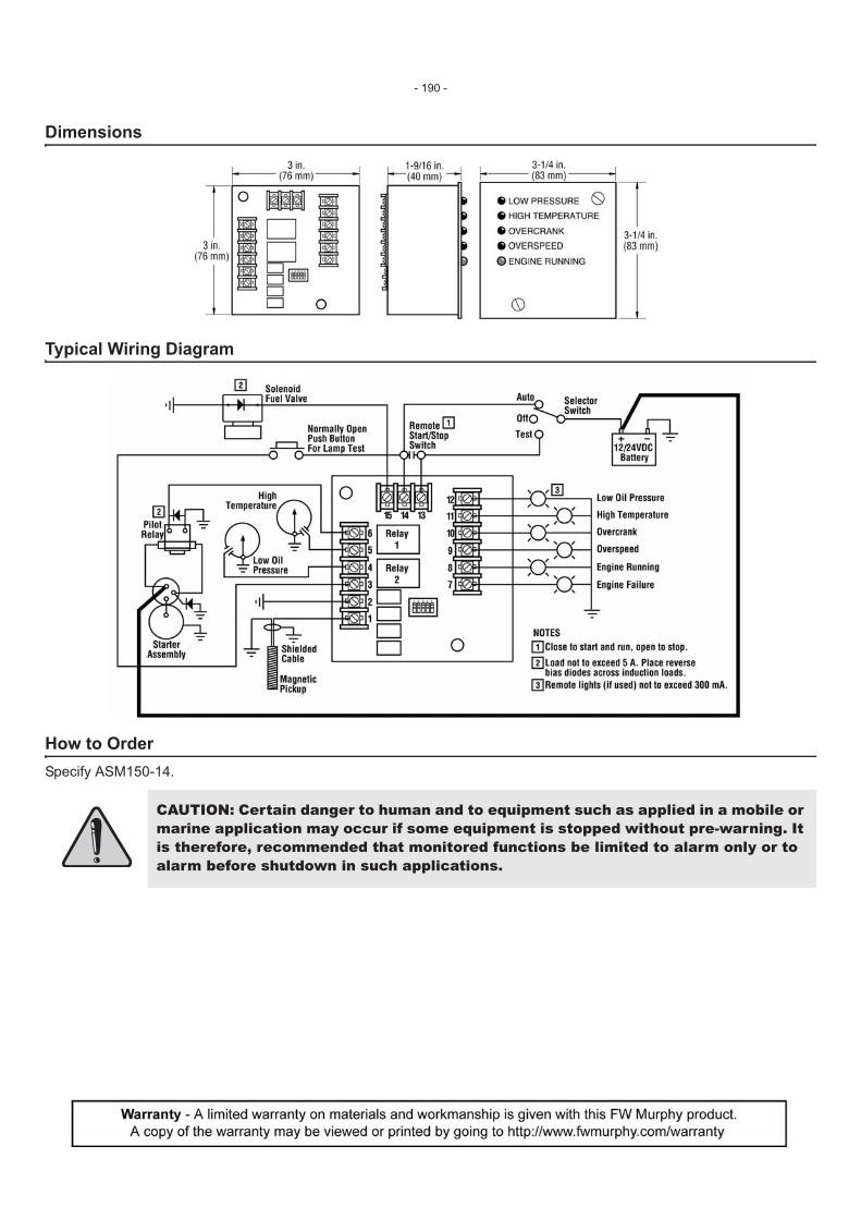
Dimensions
Typical Wiring Diagram
How to Order Specify ASM150-14.
CAUTION: Certain danger to human and to equipment such as applied in a mobile or marine application may occur if some equipment is stopped without pre-warning. It is therefore, recommended that monitored functions be limited to alarm only or to alarm before shutdown in such applications.
- 190 -
03021Revised 01-15-10
Section 40
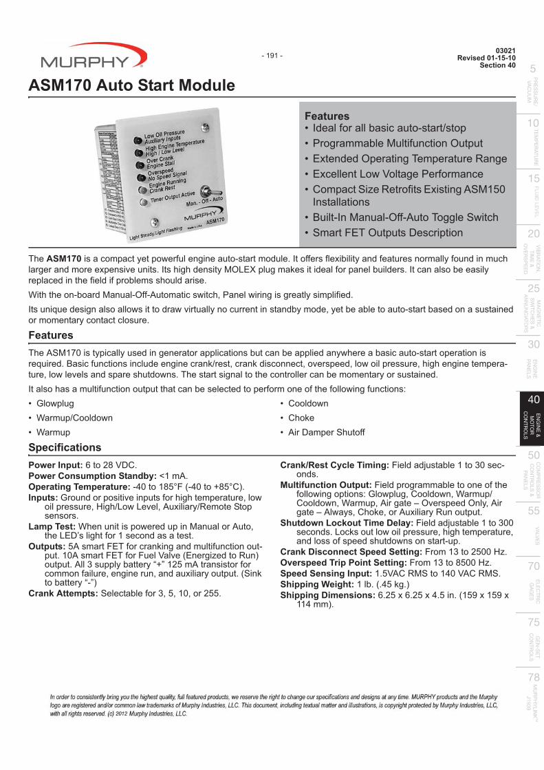
ASM170 Auto Start Module
The ASM170 is a compact yet powerful engine auto-start module. It offers flexibility and features normally found in much larger and more expensive units. Its high density MOLEX plug makes it ideal for panel builders. It can also be easily replaced in the field if problems should arise. With the on-board Manual-Off-Automatic switch, Panel wiring is greatly simplified. Its unique design also allows it to draw virtually no current in standby mode, yet be able to auto-start based on a sustained or momentary contact closure.
Features The ASM170 is typically used in generator applications but can be applied anywhere a basic auto-start operation is required. Basic functions include engine crank/rest, crank disconnect, overspeed, low oil pressure, high engine tempera-ture, low levels and spare shutdowns. The start signal to the controller can be momentary or sustained. It also has a multifunction output that can be selected to perform one of the following functions: � {��%����� }�����`������%�� }�����
� ������%�� �+���� ���$������+��;;
Specifications Power Input:��'Q<$�@Power Consumption Standby: <1 mA. Operating Temperature:�?J�>QVW�&�?J�XQVW�*@Inputs:{��������� ��=����� ;��+��+���������~��%
oil pressure, High/Low Level, Auxiliary/Remote Stop sensors.
Lamp Test: When unit is powered up in Manual or Auto, +�"�$� ���+;��> ������ �� @
Outputs: 5A smart FET for cranking and multifunction out-put. 10A smart FET for Fuel <��=�&������^������*output. All 3 supply battery “+” 125 mA transistor for common failure, engine run, and auxiliary output. (Sink �!�������*
Crank Attempts: Selectable for 3, 5, 10, or 255.
Crank/Rest Cycle Timing: Field adjustable 1 to 30 sec-onds.
Multifunction Output: Field programmable to one of the ;����%�������� �{��%����~������%�~}�����`������%�~}�����~��������=�� ��������~���������%�� ~�+���~�� Auxiliary Run output.
Shutdown Lockout Time Delay: Field adjustable 1 to 300 seconds. Locks out low oil pressure, high temperature, and loss of speed shutdowns on start-up.
Crank Disconnect Speed Setting: From 13 to 2500 Hz. Overspeed Trip Point Setting: From 13 to 8500 Hz. Speed Sensing Input:>@V<���|��>?J<���|�@Shipping Weight:>�!@&@?V��@*Shipping Dimensions: 6.25 x 6.25 x 4.5 in. (159 x 159 x
>>?��*@
Features� �����;�����!� ������ ��` ��� ���������!��|���;����������� �\�������������#��������������� �\������"�%<��������;�������� ��������^�����;� �\� �����|>VJ
Installations� �������|�������;;����#������%��+� ������#���� $� �������
- 191 -
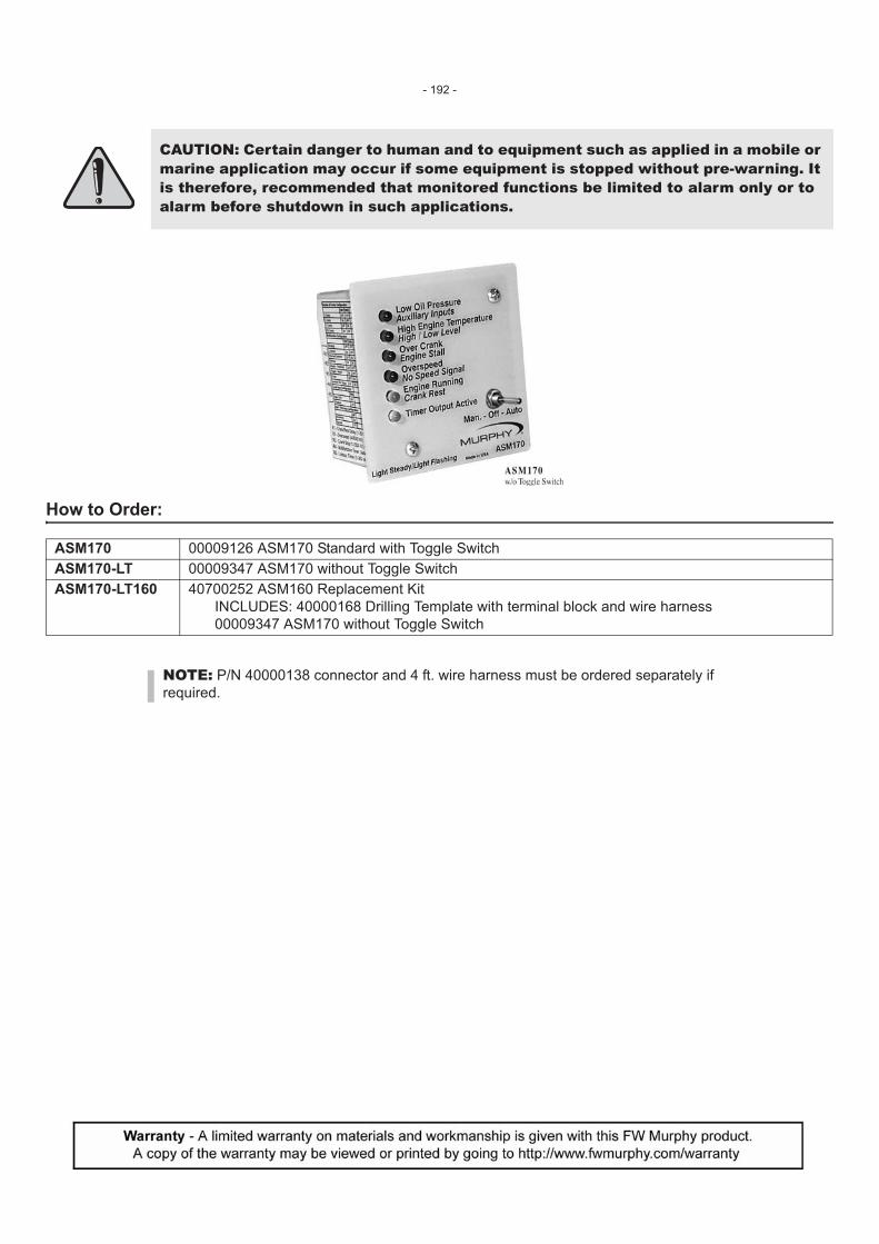
How to Order:
CAUTION: Certain danger to human and to equipment such as applied in a mobile or marine application may occur if some equipment is stopped without pre-warning. It is therefore, recommended that monitored functions be limited to alarm only or to alarm before shutdown in such applications.
ASM170 00009126 ASM170 Standard with Toggle Switch ASM170-LT 00009347 ASM170 without Toggle Switch ASM170-LT160 40700252 ASM160 Replacement Kit
INCLUDES: 40000168 Drilling Template with terminal block and wire harness 00009347 ASM170 without Toggle Switch
NOTE: P/N 40000138 connector and 4 ft. wire harness must be ordered separately if required.
- 192 -

97079Revised 07-99
Section 40
MURPHYMATIC® Engine Micro-Controller A91 Series
A completely unattended startup/shutdown and run controller for engine driven equipment. This user friendly, compact, state-of-the-art microprocessor based controller, covers all basic start stop operations plus other features only found on more sophisticated and expensive controllers. The A91 is designed to operate from a 12 or 24 volt battery, and requires a magnetic sensor (pickup) for speed detection. It includes features, such as crank and rest cycles, time delay lockouts, sensing circuit for crank disconnect and over-speed, time delays before start and stop. Warmup and cool down are connected only on the WC model. Four LED’s indicate shutdown for: low lube oil, high temperature, over crank and over- speed, and are reset by turn-ing the power off. A fifth LED for engine running indicates when crank disconnect occurs. The micro-controller is available in several configurations and is factory programmed. Certain parameters can be field adjusted without altering the basic control program. Custom programming of the microchip is available to OEM’s and quantity orders. The A91 is housed in a NEMA 3R enclosure with a hinged and gasketed dead front door. This weatherproof enclosure includes two 1/2 in. conduit holes, [7/8 in. (22 mm) diameter] in the bottom for input and output wiring. All of the electrical components are installed on a “box” shaped, hinged front sub panel assembly. This working assembly can be purchased and installed in the user’s choice of enclosures.
Applications A variety of applications can be covered with the micro-controller such as: � ���`{� ������ �� � ����!�{��������� � ����`��������`������������������
� ��� ��`#��� ;������ � |����������� +`}� �}���#������� ��%���"�;�����
Models Available A91: For less than 5 amp current draw up to 24 VDC electric run output* A91-S: For 10 amp current draw up to 240 VDC electric run output*
A91-WC:����� ��>�%�+�%�����`������%������@A91-S-WC:����� ��>���%�+�%�����`������%������@Any Model -LC: Less weatherproof enclosure.
Features #+���>����� ���!��� +���=����� �; ���� ����������cessor control logic with the dependability of Murphy’s experience in Engine Automation �� �� @#+� ����������������������� +�����;���� ��ectromechanical logic and control relays, while providing built-in design features: � �������!������#��� �;������ � ��������������� ���������%�+�
� ���� �!�������$� ��������|� ���� �!���=�� ������|
� #+������ ������������%��+����% for “Automatic” “Off” or “Test” mode.
� �������������"�$��������� ������� ����+���%�"�$�������� ;���
� "�%"�!����� ]��+#���������� �=�������� �=�� ����
� ������>�����#������������� ��+�� ��;���������������� �� ��~����� ��~���@�@
contacts close to start, close to stop. � ����� �������������%�+"�$����cator for fast service and mainte-
nance.
Optional Features -S: Includes a relay to isolate magneto and capacitor discharge igni-
tion systems. -WC: Includes a relay for loading and unloading driven equipment for
engine warmup and cooldown.
Features� |��������� ���� ���������
Controller� ��������������!��#������� � ��=�"�$�������������� � �����"�����#����� ����;��� }�+�+���\� ���|���+�
������ � ��|�Z��}��+������;������ ���
Description
* Run output is the voltage and current required for an ignition system, fuel valve, or solenoid actuator that allows the engine to run.
- 193 -

Specifications Power Input: 12 or 24 VDC nominal (specify). Standby Power Consumption: <50mA. Magnetic Pickup Input: Requires 2 V rms minimum. Sensor Input Polarity: Negative (-). Outputs: Five (5) open collector transistor 500 mA sink.
Two (2) relay, 5 Amp maximum at 12 or 24 VDC (sourcing). Reverse Polarity Protection: 200 volt peak reverse voltage. On-board Memory: 8k PROM (programmable, read only memory); data
retention 10 years. Operating Temperature Range: -20 to 140?F (-25 to 60°C). Operating Humidity Range: 0-95% Non-Condensing User Trip point Adjustments: Five (5) on-board potentiometers (320°
turn). Test-Off-Automatic Toggle Switch: Three position switch for:
� #� ���� ������������������������� ���� %��+����;;�or emergency shutdown occurs.
� �;;�$� ������ �����%��������������� ~���`�� �!�� ������from starting and resets shutdown indicators.
� ����������� ��` �� �_����ing is initiated by external switches and signals.
Cycle Crank Timer: 5 crank attempts 7 seconds each; 4 rest periods 15 seconds each, before overcrank.
Overspeed Trip Point Setting: From 2500-9000 Hz. Crank Disconnect Speed Setting: From 400-2500 Hz. Shutdown Time Delay: 15 seconds after engine start; locks out low lube
oil and high temperature. Engine Run LED:#��� ����%+��������� ����������� @Shutdown Output: Removes DC output or operates dry relay contacts for
engine shutdown (depending on model used). Start/Stop: ��$#��������������#��������� %��+� @Warmup Time Delay: Field adjustable from 0-300 seconds to load the
engine after warmup (model -WC only). Cooldown Time Delay: Field adjustable from 0-300 seconds (model -WC
only). Enclosure: Weatherproof NEMA 3R. Enclosure Coating: Red enamel.
Dimensions
How to Order
Accessories MP3298: Magnetic pickup. 00002062: 12 V auxiliary starter solenoid. 00002063: 24 V auxiliary starter solenoid. AT67207: Throttle controller. CO3: Clutch actuator.
NOTE: Run output is 5 amp @ 12 or 24 VDC. Run output is the voltage required for an ignition system, fuel valve, or solenoid actu-ator that allows the engine to run.
- 194 -

05195Revised 03-15-11
Section 40 & 75
Auto-Start/Stop Controller — Cascade
The Cascade controller offers automatic start and stop control with easy configuration for a broad number of applications. This auto-start controller is designed to fit any engine-driven application requiring a simple and robust automatic start and stop sequence. Pumps, Compressors, Grinders, Power Units and Generators are just few of the industrial applications for the controller. The Cascade controller is fully compatible with all major engine types. Whether you are running mechanical or J1939 engines, the controller will work with your application. Here are some of the unique features of the Cascade that only Murphy can offer at our competitive price. � Durability: Encapsulated to protect it against dirt, water and dust, along with a compression gasket to fully seal it to the
panel. Cascade is rated NEMA4 and IP65.� Low Battery Blackouts: Operates in total blackout for a minimum of two seconds.� Compatibility: Accept MPU, AC Frequency and ECU speed signals and can operate with standard and J1939 engines.� Inputs and Outputs: The Cascade Inputs and Outputs are ruggedly protected and fault tolerant.� J1939 Ready: Works directly with Murphy’s J1939-ready PowerView gages, just plug and go, no sender is required. � CD101 Cascade Configuration Tool: Allows quick setup and loading of parameters into a Murphy standard Cascade
via a PC software tool.
Specifications Power input: 9-35VDC continuous - operates during total black-
out for 2 seconds minimum. Power consumption: Sleep Mode (Manual): 1mA typical; Sleep
Mode (Automatic): 4mA typical. Running Mode (Manual): 20mA typical; Running Mode (Automatic): 24mA typical.
Operating/Storage temperature: -40 to 85°C; (-40 to 185°F). Humidity: 0-100%, non-condensing. Housing: UV stabilized black polycarbonate and epoxy encapsu-
lation. Weather tight and includes sealing gasket to keep moisture and debris out of enclosure. Properly mounted con-troller will maintain NEMA4 / IP65 rating of enclosure.
Vibration: Rated to 6G. Impact: Rated to 10G. Inputs: Dedicated digital inputs for low oil pressure, high engine
temperature, remote start, DC charge fail/Alternator fail. Two aux inputs are configurable for multiple functions.
Outputs: 7 – 4 auxiliary, configurable (1A DC protected). 3 dedi-cated outputs for Crank, Fuel/ECU, Alternator excitation.
Crank attempts: 3, 5, 10, Continuous. Crank Rest: 5-60 seconds, adjustable. Shutdown lockout time delay: 5, 10, 15, 20, 25, 30 seconds. Crank disconnect speed setting: Field settable 0-9999 RPM
(16-60Hz AC freq input). Overspeed/underspeed trip point setting: ±5 to 50% of nomi-
nal. Speed sensing inputs: Magnetic pickup (5-120VAC RMS / 0-10
kHz) & AC frequency (30-600VAC RMS / 16-80 Hz). CANbus interface: Directly reads engine speed, & engine status
data* from SAE-J1939 enabled engines. MODbus interface: In J1939 applications drives PVA series
analog gages.
Features� $���!������� �����protection against
dirt, water, and dust – rated NEMA4 and IP65
� ������ ��������%!����!������ � ������!��%�+ Electronic and
Mechanical engines – ECU, MPU, AC Frequency
� �>�Z�������}��� �������%�+MurphyLink J1939 PowerView gages
*Engine status data limited to low oil pressure, high engine temperature, “Wait to start” status, Warning & Fault lamp information, and communication error.
- 195 -
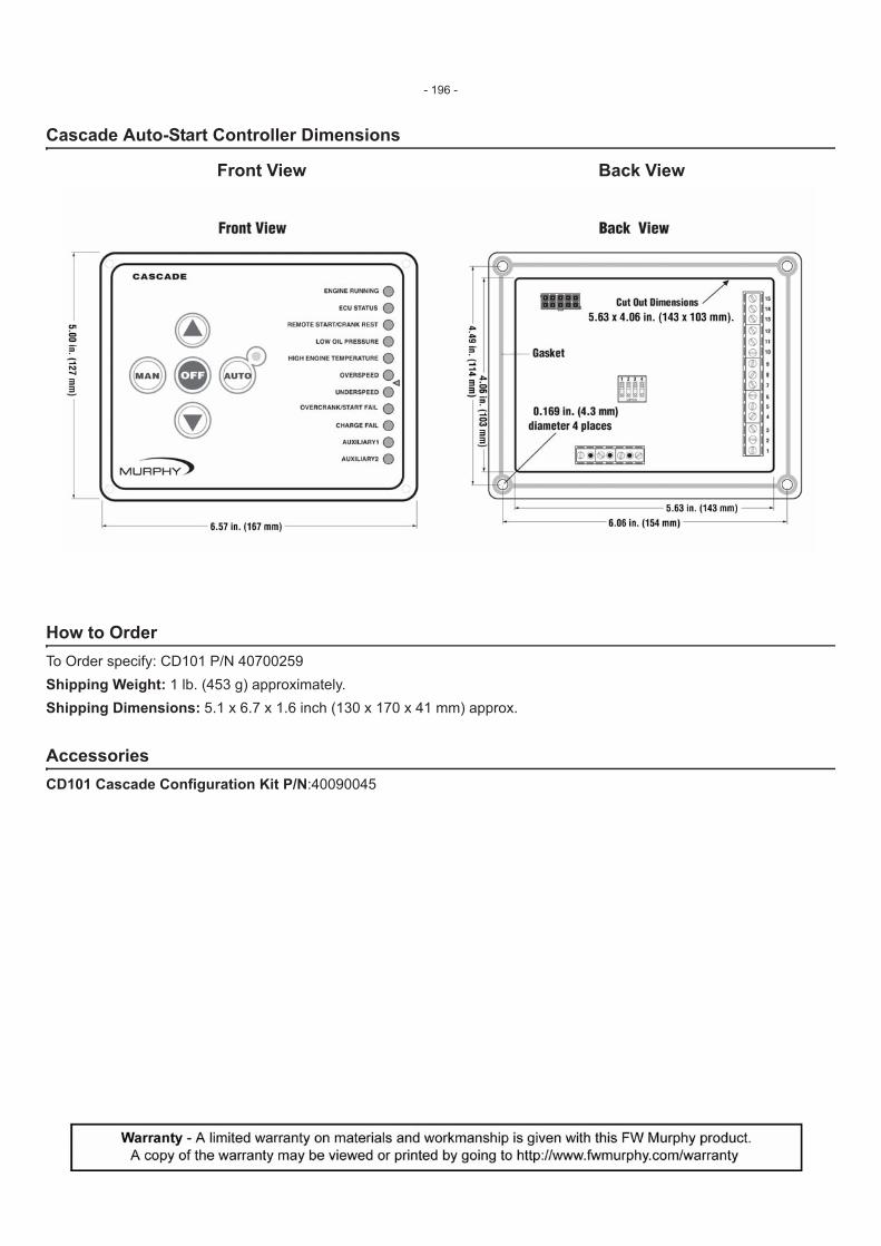
Cascade Auto-Start Controller Dimensions
Front View Back View
How to OrderTo Order specify: CD101 P/N 40700259Shipping Weight: 1 lb. (453 g) approximately. Shipping Dimensions: 5.1 x 6.7 x 1.6 inch (130 x 170 x 41 mm) approx.
AccessoriesCD101 Cascade Configuration Kit P/N:40090045
- 196 -

101055405-31-11
Section 40
EMS PRO - Engine Monitoring System Controller
The EMS PRO is a flexible all-in-one customizable unit that meets the needs of engine-driven pumping equipment applica-tions. The EMS PRO is a dedicated microprocessor-based, single engine controller. It offers field-adjustable operating parameters that can be changed without the need for a computer. It is also able to support both mechanical and J1939 electronic engines. The EMS PRO has selectable auto start/stop features with several throttling options. The auto start/stop options (Single Contact, Floats, Momentary, Transducer and Clock) are available at the touch of a button. The Transducer start/stop option includes three settings; pressure, level and temperature. In addition, there are many performance-enhancing features, all of which are available through an operator interface that is easy to learn and use. The EMS PRO is ideal for use with a remote modem or in a SCADA system offering Modbus RTU protocol on either the RS232 or RS485 port.The EMS PRO has the ability to withstand a wide ambient temperature range and comes standard in a NEMA 4X rated enclosure secured by four rubber shock mounts. Inside is a backlit graphical display visible day or night and under all kinds of conditions.
CommunicationsThe EMS PRO has RS485, RS232 and J1939 CAN communication ports. The standard unit uses RS485 or RS232 for Modbus RTU. At the same time, the CAN port allows J1939 communication with the engine ECU to display engine param-eters and control the throttle via TSC1 if supported by the engine.
How to OrderP/N 40-70-0301 EMS PROP/N 40-70-0302 EMS PRO with Optional Clear Door
NOTE: Care should be taken when selecting the optional clear door when used in applications involving direct sunlight exposure. Direct sunlight can cause premature component failure by allowing the sealed enclosure temperature to exceed the rated 80oC/175oF.
AccessoriesThe EMS PRO has (2) Deutsch HDP connectors, 21 pin and 31 pin, for easy field wiring.Harness Options:� �`�?J�JJ�J?z��|����'>�����Z>��������������� �`�?J�JJ�J?QJ�|����>J�'>�����Z>����]���� ��� �`�?J�JJ�J?Q>�|����>J�Z>�����`�]���� � |�]������]���� ����� ���������� �����anel Sales for application specific adapter harness.� |�]]���� ����� ���������� ��������� Sales for application specific MEH harness.
Features� ������ |��+����������>�Z���������������� � ����������`���� ������{���+����$� ����� �+���%�]� �������� ��� ����+���%� ���`����������������"�$ � ��������� �!���������� � ������ #��>#+rottle Messaging� }�����������#��������������� ��������� �����������[���^���Modbus® RTU with Auxiliary
Equipment� ����#����������'?]��������� ��|�? ����� ���%�+������������$���
*
Shown withoptional clear door.
¡�����=�� !� ��� ;�� ����+�^����� ������� &{���� ��;����!�����������>J>J�>*
- 197 -

Specifications
Operating Voltage (12 and 24 systems):� Q<$���������Z'<$���\����EnvironmentalOperating Temperature: �?JW�QJW�&�?JW�>z�W�*
NOTE:���� +����!�����%+�� �������+���������������%+��� �������������� ��=��=��� �����+�\�� ���@$���� �����+������ �����������������;������!�����%���+� ���������� ��������������\����+�����QJ��`>zV��@
Storage Temperature: �?JW�QJW�&�?JW�>z�W�*
Environmental Sealing: ����NOTE: |�� ����%+��+������ ��� ��AND���+��@
Relative Humidity: �V¢�]£�JW�Standby Current:� &£>'<$�*''J��� &£'?<$�*'VV��CAN Bus: ����>�Z���������Enclosure:�������!������|�? &["����;���*
Inputs:���������� � &>'*�� ������=���������� �����`������������~?�'J��~J�V<$�@$��������� �&Q*+��+`��%���_������>���������� ���������;�� ������;������~
��������������@&'<���VJ<���|�*���������������ZZ�+�;���~'?J�+�����Outputs:$��������� � &Z*��#�X&�����>�*����� � >��$#���Q���#V������������ &��\����������������������������'Z��� *@User Interface: &Q*!������!���� %��+Connectors: '>������Z>���$�� �+]$�'J����� Mounting: ?� �����@zV���+��!!�� +������� Shipping Weight: >>"!@&V��@*Shipping Dimensions (all models):� >V\>V\>>��@&ZQ>\ZQ>\'z�@?��*
Product Dimensions
- 198 -

111077001-16-12
Section 40
EMS PRO LITE Engine Monitoring System Controller
Features� ������ |��+����������>�Z���������������� � ����������`���� ������{���+����$� ����� �+���%�]� �������� ��� ����+���%����`����������������"�$ � ��������� �!���������� � ������ #��>#+����|� ������ }�����������#��������������� ���V����� ����������������^���|��!� ¤�#[%�+��\�������_������
#+��|����"�#�� ��� ���^�!������������������ ����� ����;������%�+��%���������������������������� ������@#+� =�� ������� ����� !�+|��+����������>�Z���������������� ~+� ����������+������ ������������������� @� ���+���~+��|����"�#�� #���?���������`�<�����@
#+������������;���� ��� ��� �=�Q�!������!�������������!���������+������ ������������������+�;����;���������|�?����� ���@
����������� ���!� �����������~+��|����"�#����������������� ���;��������� �!��%�+��+�����;����������@]�%�=��~+��|����"�#����!�����;���;��� �%�+�������������������$� � ��%�+|�$�� ¤�#[������� ����+������'Z'����?QV���@
�|����"�#��;;�� ������`���%�+'��������#��� ����� ���� &��� ��������=��*@#+�����"�=��~��� ���~����\������|&�� ������|*� �;;����@
#+���!� �|����"�#�� ����������;��>'<$� � �� &Q<$���������>?@?<$���\����*����%��������������������@�������� ������� ��� ������$�� �+;�� ������� ���������_������ ������@
How to OrderPart # Description?JzJJZJV�|����"�#�Accessories?JJJJV'>'>������������~>J;&Z@J?Q�*}+��]���� ��;��|��+������������ ?JJJJV''�����~>J;&Z@J?Q�*}+��]���� ;���`�?JJJJV'Z���������������;���`�%�+������� ?JJJJV'?'>����������������������%�+������� |�]������]���� ����� ���������� ������������� ;������������ ����;��������+���� @|�]]���� ����� ���������� ������������� ;������������ ����;��|�]+���� @
Communications#+��|����"�#�+� ��?QV~��'Z'����>�Z������������������� @#+� ���������� � ��?QV����'Z';��|��!� �#[@�+� ������~+�����������% �>�Z�������������%�++���������[��� ������������������ ���������+�+����=��#��>~�; �������!�+�������@
- 199 -
Specifications
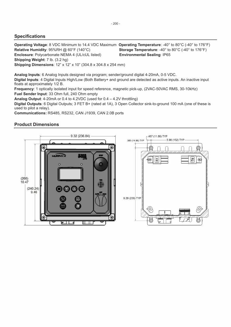
Operating Voltage: 8 VDC Minimum to 14.4 VDC Maximum Operating Temperature: -40° to 80°C (-40° to 176°F)Relative Humidity: 95%RH @ 60°F (140°C) Storage Temperature: -40° to 80°C (-40° to 176°F)Enclosure: Polycarbonate NEMA 4 (UL/cUL listed) Environmental Sealing: IP65Shipping Weight: 7 lb. (3.2 hg) Shipping Dimensions: 12” x 12” x 10” (304.8 x 304.8 x 254 mm)
Analog Inputs: 6 Analog Inputs designed via program; sender/ground digital 4-20mA, 0-5 VDC. Digital Inputs: 4 Digital Inputs High/Low (Both Battery+ and ground are detected as active inputs. An inactive input floats at approximately 1/2 B.Frequency: 1 optically isolated input for speed reference, magnetic pick-up, (2VAC-50VAC RMS, 30-10kHz)Fuel Sender Input: 33 Ohm full, 240 Ohm emptyAnalog Output: 4-20mA or 0.4 to 4.2VDC (used for 0.4 – 4.2V throttling)Digital Outputs: 6 Digital Outputs; 3 FET B+ (rated at 1A), 3 Open Collector sink-to-ground 100 mA (one of these is used to pilot a relay).Communications: RS485, RS232, CAN J1939, CAN 2.0B ports
Product Dimensions
- 200 -

0910364Revised 03-02-10
Section 40
EMS467 Monitoring System
The EMS467 Electronic Monitoring System/Controller is micro-processor based for monitoring and control of equipment functions. It is especially suited to tasks requiring remote modem or SCADA communications. The four built-in communication ports provide a variety of communications capabilities.
Basic programs provide selectable auto or manual start/stop and first-out shutdown for engine functions such as pressure, temperature, level and overspeed. Time delays for lock out during start up are included. The EMS467 can be applied as an RTU to interface between SCADA applications and other control platforms.
With an inexpensive wireless data modem attached, the EMS467 can be used for remote monitoring and control through the internet. The unit can send emails, serve web pages, and transmit data to remote servers.
An external PC card reader can be used with the EMS467 to log data from flow meters, pressure transmitters, electric gauge senders, and other sensing devices. This is a popular application in the flood control market.
Operating data is displayed on a 32 character back-lit alpha-numeric liquid crystal display. An on-board real-time clock keeps a log of equipment running hours and alerts you when to change oil, filters and perform other routine service.
The EMS467 operating parameters are configured through a simple three-button interface. Access to the system memory is controlled by entry codes.
A password-protected program uses a built-in memory to display the alarm/shutdown history, including a display of the last ten shut-downs, when and why they occurred, and displays all of the engine operating conditions at the time of the last shutdown.
CommunicationsThe EMS467 has one RS485, one RS232, and two J1939 CAN communication ports. By using these ports and the necessary software, you can monitor and control your equipment from a remote location.
With the CAN ports, you can communicate to an electronic engine and display engine operation information on the display.
Sensor InputsDigital Inputs (DI) - Number of devices: 8Device types: discrete input, optically isolated, normally open (N/O) or normally closed (N/C), bi-polar (active high positive voltage/active low negative voltage), non-incendive.
Analog Inputs (AI) - Number of devices: 8 Device types: analog input (7-field selectable, 1-dedicated for battery voltage), accepts 4/20mA, 0-5 VDC, or Murphy (or equivalent) resistance type senders (two-wire type senders is recommended). 10 bit hardware.
Frequency Pickup - Number of devices: 1Device types: magnetic pickup (MPU), 5 to 120 Vrms, 30 to 10k Hz. - Optically Isolated
Digital Outputs (DO) - Number of devices: 7Device types: discrete output, normally open (N/O) or normally closed (N/C) 200mA sinking (DC-). Outputs 4 and 5 have flashback diodes and include software interrupts for high speed throttling. (i.e. Murphy AT03069)
Analog Outputs (AO) - Number of devices: 1Device types: analog output, 0.5-4.2 VDC, 8 bit hardware
Features� ������������ ��������� �!���������� � ��� ����+���%� ���`������� � �+���%�]� �������� ���=����������� � ���������������� ��� � ����"����+��������$� ����� ��� +���������!��� �����=��;����� �~$�=� ���2 Groups A, B, C, D Hazard-
ous locations.
- 201 -
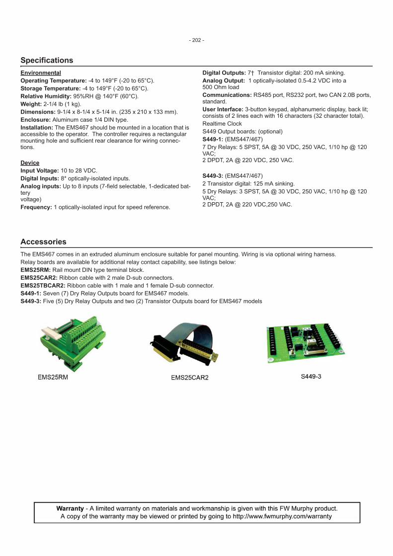
Specifications Environmental Operating Temperature: -4 to 149°F (-20 to 65°C).Storage Temperature: -4 to 149°F (-20 to 65°C).Relative Humidity: 95%RH @ 140°F (60°C).Weight: 2-1/4 lb (1 kg).Dimensions: 9-1/4 x 8-1/4 x 5-1/4 in. (235 x 210 x 133 mm).Enclosure: Aluminum case 1/4 DIN type.Installation: The EMS467 should be mounted in a location that is accessible to the operator. The controller requires a rectangular mounting hole and sufficient rear clearance for wiring connec-tions.
DeviceInput Voltage: 10 to 28 VDC.Digital Inputs: 8* optically-isolated inputs.Analog inputs: Up to 8 inputs (7-field selectable, 1-dedicated bat-tery voltage)Frequency: 1 optically-isolated input for speed reference.
Digital Outputs: 7† Transistor digital: 200 mA sinking.Analog Output: 1 optically-isolated 0.5-4.2 VDC into a 500 Ohm loadCommunications: RS485 port, RS232 port, two CAN 2.0B ports, standard.User Interface: 3-button keypad, alphanumeric display, back lit; consists of 2 lines each with 16 characters (32 character total).Realtime ClockS449 Output boards: (optional)S449-1: (EMS447/467) 7 Dry Relays: 5 SPST, 5A @ 30 VDC, 250 VAC, 1/10 hp @ 120 VAC; 2 DPDT, 2A @ 220 VDC, 250 VAC.
S449-3: (EMS447/467) 2 Transistor digital: 125 mA sinking.5 Dry Relays: 3 SPST, 5A @ 30 VDC, 250 VAC, 1/10 hp @ 120 VAC;2 DPDT, 2A @ 220 VDC,250 VAC.
AccessoriesThe EMS467 comes in an extruded aluminum enclosure suitable for panel mounting. Wiring is via optional wiring harness.Relay boards are available for additional relay contact capability, see listings below:EMS25RM: Rail mount DIN type terminal block.EMS25CAR2: Ribbon cable with 2 male D-sub connectors.EMS25TBCAR2: Ribbon cable with 1 male and 1 female D-sub connector.S449-1: Seven (7) Dry Relay Outputs board for EMS467 models.S449-3: Five (5) Dry Relay Outputs and two (2) Transistor Outputs board for EMS467 models
- 202 -

92199Revised 05-03
Section 40
Electronic Monitoring Systems EMS447 / EMS448 Controllers
The EMS447 and EMS448 Electronic Monitoring Systems/Controllers are micro-processor based for monitoring and control of equipment functions. The basic EMS system is programmed for a typical industrial engine power unit. Custom programming is available to adapt the EMS to a wide variety of engine and equipment requirements. Basic programs provide auto-start/manual start and first-out shutdown for engine functions such as pressure, temperature, level and overspeed. Neces-sary time delays for start up lockout are included. Operating data is displayed on a 32 character back lit alphanumeric liquid crystal display. The EMS operating parameters are configured through a simple three-button interface. Access to the system memory is controlled by entry codes. A password-protected program uses built-in memory to display the alarm/shutdown history, including a display of the last ten shutdowns, when and why they occurred and displays all of the engine operating conditions at time of last shutdown.
Basic Program Features An on-board hourmeter keeps a log of equipment running hours and alerts you when to change oil, filters and perform other routine service. Ramp Oil Pressure monitoring protects equipment at both high rated speed and low idle speed. For instance, based on engine manufacturer’s require-ment, shutdown could occur at 30 lb. (207 kPa) pressure at 1800 RPM or at 5 lb. (34 kPa) at 600 RPM or any shutdown point in between.
Basic Models EMS447 has an extruded aluminum enclosure suitable for panel mounting. Wiring is via optional wiring harness. Relay boards are available for additional
relay contact capability. Refer to “Accessories” on the back page. EMS448 has a NEMA 4X type enclosure. Wiring is connected directly to the relay board terminal block located within the enclosure. Relay board for addi-
tional relay contact capability is available. See “Optional Accessories” on reverse side.
Applications � ���� ���������� � ������ �� � {�������
� #���� � ��� �������_������� ����
Specifications Input Voltage: 10 to 28 VDC. Operating Temperature: -4 to 149°F (-20 to 65°C). Storage Temperature: -4 to 149°F (-20 to 65°C). Display: Alphanumeric: 2-line, 32 character backlit LCD (standard); VFD
optional. Relative Humidity: 95%RH @ 140°F (60°C). Communications: RS485 port, standard. Sensor Inputs:
� Digital: 3-optically-isolated inputs, (positive voltage or ground) ��+� ;���|���+��}��]{�{�® instruments.2 3
� Analog: Up to 8 inputs–accepts a variety of resistive sending units, such as from Murphy electric gage senders.
� Frequency: 1 optically-isolated input for speed reference, such as MP3298 magnetic sensor.
EMS447 Outputs: � Z�#��� � ���������>'V�� ������@5� Z����������#Z�£ZJ<$��@�@connected to battery positive4. � S449-4 Relay Board (optional)4: 2-Transistor digital: 125 mA
sinking. 5-Relay: 3-SPST, 5A @ 30 VDC, 250 VAC, 1/10 hp @ 120 VAC; 5 2-DPDT, 2A @ 220 VDC,250 VAC. 6
� S449-2 Relay Board (optional)4: 7-Dry Relay: 5 SPST, 5A @ 30 VDC, 250 VAC, 1/10 hp @ 120 VAC; 5 2 DPDT, 2A @ 220 VDC, 250 VAC. 6
EMS448 Outputs: � '�#��� � ���������>'V�� ������@� V�������Z����#~V�£ZJ<$�~'VJ<��4, 1/10 hp @ 120 VAC; 5
2-DPDT, 2A @ 220 VDC,250 VAC. 5� S449-1 Relay Board (optional)4: 6-Dry Relay: 4 SPST, 5A @ 30
VDC, 250 VAC, 1/10 hp @ 120 VAC; 5 2 DPDT, 2A @ 220 VDC, 250 VAC.6
Shipping Weights and Dimensions EMS447: 2-1/4 lb (1 kg); 9-1/4 x 8-1/4 x 5-1/4 in. (235 x 210 x 133 mm). EMS448: 3-1/2 lb (1.5 kg); 12-1/4 x 7-1/4 x 5-3/4 in. (311 x 184 x 146 mm).
Features� �����_��������������1
� ��������� �!���������� 1
� ��� ����+���%� ���`������� 1
� �+���%�]� �������1
� ���=����������� 1 � ����"�"�$��<�$���+��������$� ��������� >`?$������|�4X Enclosed Models
1 Program specific
2 One additional input can be ordered and traded for one transistor output. 3 Isolates the internal circuitry of the Murphy EMS from the sensor input circuitry to help avoid
electrical noise and damage.
NOTE: When resistive sending units are used, one input will be designated for battery voltage sensing. The use of 2-wire type senders is strongly recommended. Special order analog inputs available (4-20 mA or 0-5 VDC).
4 Not Class I, Division 2 approved.5 One additional output can be ordered and traded for one digital input. 6 One DPDT pole has common connected to battery+. N.O. available fused and unfused.
Approved for C1, I, Div-2, Grps, C&D areas on EMS447 (all transistor outputs) and EMS448 (board only)
- 203 -
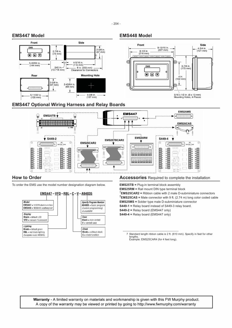
EMS447 Model EMS448 Model
EMS447 Optional Wiring Harness and Relay Boards
How to Order To order the EMS use the model number designation diagram below.
Accessories Required to complete the installation EMS25TB = Plug-in terminal block assembly EMS25RM = Rail mount DIN type terminal block 7EMS25CAR2 = Ribbon cable with 2 male D-subminiature connectors 7EMS25CAS = Male connector with 9 ft. (2.74 m) long color coded cable EMS25MS = Solder type male D-subminiature connector S449-1 = Relay board instead of S449-3 relay board. S449-2 = Relay board (EMS447 only) S449-4 = Relay board (EMS447 only)
7 Standard length ribbon cable is 2 ft. (610 mm). Specify in feet for other lengths. Example: EMS25CAR4 (for 4 feet long).
- 204 -

95122Revised 05-03
Section 40
Electronic Monitoring System/Controller – Model EMS547
The EMS547 Electronic Monitoring System/Controller is micro-processor based for monitoring and control of equipment functions. It is especially suited to tasks requiring remote modem or SCADA communications. Four built-in communication ports provide a variety of communications capabilities. Basic pro-grams provide selectable auto or manual start/stop and first-out shutdown for engine functions such as pressure, temperature, level and overspeed. Time delays for lockout during start up are included. The EMS547 can be applied as an RTU to interface between SCADA applications and other control platforms. It can also be used, in conjunction with a Hayes compatible modem (9600 Baud), for remote communications. An external PC Card reader can be used with the EMS547 to log data from flow meters, pressure transmitters, electric gage senders, and other sensing devices. This is a popular application in the flood control market. Operating data is displayed on a 32 character back lit alphanumeric liquid crystal display. An on-board real-time clock keeps a log of equipment running hours and alerts you when to change oil, filters and perform other routine service. The EMS547 operating parameters are configured through a simple three-button interface. Access to the system memory is controlled by entry codes. A password-protected program uses built-in memory to display the alarm/shutdown history, including a display of the last ten shutdowns, when and why they occurred, and displays all of the engine operating conditions at time of last shutdown. Because of the flexibility of this product, please call one of our application specialists to see how best to apply the EMS547. We have a growing library of standard programs or we can write a program to your specific needs.
Applications � ���� ���������� � �������|��� � {������� � ��� �������_������� ����������������
� ������ �� � #���� � ���� � ���$�
Specifications Input Voltage: 10 to 28 VDC. Operating Temperature: -4 to 149°F (-20 to 65°C). Storage Temperature: -4 to 149°F (-20 to 65°C). Relative Humidity: 95%RH @ 60°C (140°F). Display: Alphanumeric: 2-line, 32 character backlit LCD (standard); VFD
optional. Communications: 2–S485, 2–S232 ports. Sensor Inputs:
Digital: 4 optically-isolated inputs, (positive voltage or ground) such � ;���|���+��}��]{�{�® instruments.
Analog: Up to 8 inputs–will accept a variety of resistive sending units, such as from Murphy electric gage senders. (When resis-tive sending units are used, one input will be designated for bat-tery voltage sensing.)
Optional: Special order analog inputs available, including end of line 4-20 mA and 0-5 VDC.
Frequency: 1 optically-isolated input for speed reference, such as MP3298 magnetic sensor.
Outputs: Transistor: 7 digital; 125 mA sinking. S449-1 Relay Board (Optional)*: 7 Dry Relay: 5 SPST, 5A @ 30
VDC, 250 VAC, 1/10 hp @ 120 VAC; 2 DPDT, 2A @ 220 VDC, 250 VAC†.
S449-3 Relay Board (Optional)*: 2 Transistor digital: 125 mA sink-ing. 4 Relay: 3 SPST, 5A @ 30 VDC, 250 VAC, 1/10 hp @ 120 VAC; 2 DPDT, 2A @ 220 VDC,250 VAC†.
Shipping Weight: 2-1/4 lb. (1 kg.). Shipping Dimensions: 9-1/4 x 8-1/4 x 5-1/4 in. (235 x 210 x 133 mm).
Features� ��������� �!���������� � ��� ����+���%� ���`������� � �+���%�]� �������� ���=����������� � ������������������� � �\��������������������|����
Ready � ����"�"�$��<�D Alphanumeric Dis-
play
�����=��;����� �~$�=� ���'~{���� ��$���� @
RRC
* Not Class I, Division 2 approved. † One DPDT pole has common connected to battery+. N.O. available fused and unfused.
- 205 -
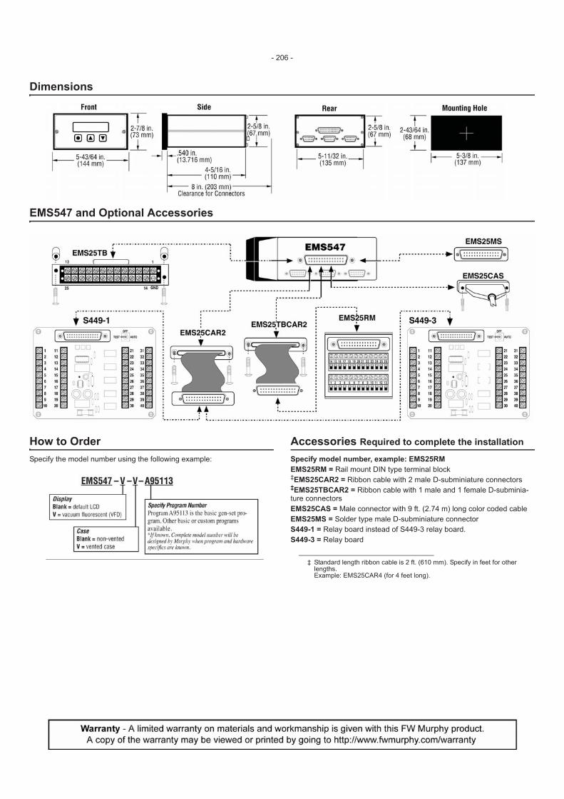
Dimensions
EMS547 and Optional Accessories
How to Order Specify the model number using the following example:
Accessories Required to complete the installation
Specify model number, example: EMS25RM EMS25RM = Rail mount DIN type terminal block ‡EMS25CAR2 = Ribbon cable with 2 male D-subminiature connectors ‡EMS25TBCAR2 = Ribbon cable with 1 male and 1 female D-subminia-ture connectors EMS25CAS = Male connector with 9 ft. (2.74 m) long color coded cable EMS25MS = Solder type male D-subminiature connector S449-1 = Relay board instead of S449-3 relay board. S449-3 = Relay board
‡ Standard length ribbon cable is 2 ft. (610 mm). Specify in feet for other lengths.Example: EMS25CAR4 (for 4 feet long).
- 206 -
00092Revised 11-03
Section 40
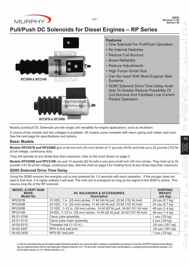
Pull/Push DC Solenoids for Diesel Engines – RP Series
Murphy push/pull DC Solenoids provide single unit versatility for engine applications, such as shutdown. A choice of two models and two voltages is available. All models come complete with return spring and rubber seal boot. See the next page for specifications and options.
Basic Models Models RP2307B and RP2308B give a full one inch (25 mm) stroke at 11 pounds (49 N) and hold up to 23 pounds (102 N) at full voltage, continuous duty. They will operate at any stroke less than maximum; refer to the chart shown on page 2. Models RP2309B and RP2310B can pull 14 pounds (62 N) with a one-and-a-half inch (38 mm) stroke. They hold up to 34 pounds (151 N) at full voltage, continuous duty. See the chart on page 2 for holding force at any stroke less than maximum.
SD85 Solenoid Drive Time Delay Using the SD85 ensures the energize coil is only powered for 1-2 seconds with each operation. If the plunger does not seat in that time, it is highly unlikely it will seat. The hold coil is energized as long as the signal to the SD85 is active. This insures long life of the RP solenoid.
Features� ������������������`�� +��������� ����������%��+� � ����������������� ��� �����!����� ���������� ��� � ]��+�������������^�� �����[ ��}�+|� ������ ���
Systems� �$QV��������$��=�#���$�����=����
able To Greatly Redu���� �!�����;���������������cilitate Low Current ��������������@
MODEL & PART NUM-BERS:
Model No. DC SOLENOIDS & ACCESSORIES
Description
SHIPPING WEIGHT ozs (kg)
��'ZJz� >'<$�~>��@&'V��* ����~>>�!;&?��*����~'Z�!;&>J'�*+��� '?�^ &J@z��*��'ZJQ� '?<$�~>��@&'V��* ����~>>�!;&?��*����~'Z�!;&>J'�*+��� '?�^ &J@z��*��'ZJ�� >'<$�~>�>`'��@&ZQ��* ����~>?�!;&�'�*����~Z?�!;&>V>�*+��� ?Q�^ &>@?��*��'Z>J� '?<$�~>�>`'��@&ZQ��* ����~>?�!;&�'�*����~Z?�!;&>V>�*+��� ?Q�^ &>@?��*65-01-0108 Clevis yoke assembly 1 ozs (.03 kg)65-01-0110 Clevis yoke chain assembly 2 ozs (.04 kg)40-05-0315 Threaded rod (1-1/2 in.) .05 ozs (.001 kg)00-00-2457 RPS in-line ball ���� @JV�^ &@JJ>��*JJ�JJ�'?VQ ����JW!������� >�^ &@JZ��*
- 207 -
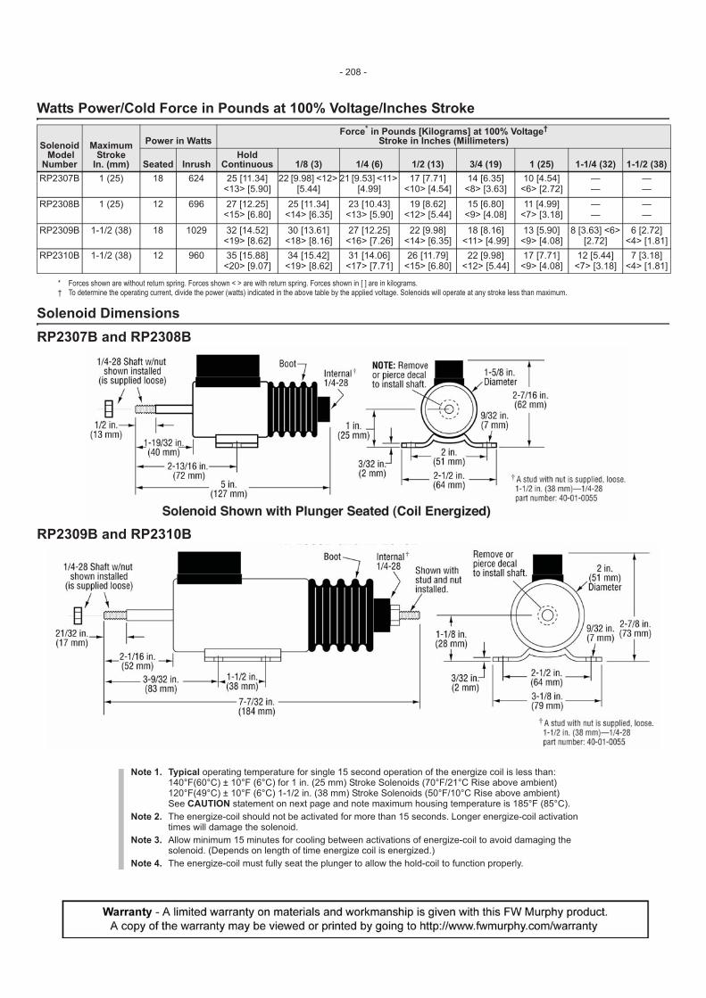
Watts Power/Cold Force in Pounds at 100% Voltage/Inches Stroke
Solenoid Dimensions RP2307B and RP2308B
RP2309B and RP2310B
Solenoid Model
Number
MaximumStroke
In. (mm)
Power in Watts Force* in Pounds [Kilograms] at 100% Voltage†
Stroke in Inches (Millimeters)
* Forces shown are without return spring. Forces shown < > are with return spring. Forces shown in [ ] are in kilograms.† To determine the operating current, divide the power (watts) indicated in the above table by the applied voltage. Solenoids will operate at any stroke less than maximum.
Seated Inrush Hold
Continuous 1/8 (3) 1/4 (6) 1/2 (13) 3/4 (19) 1 (25) 1-1/4 (32) 1-1/2 (38)RP2307B 1 (25) 18 624 25 [11.34]
<13> [5.90] 22 [9.98] <12>
[5.44] 21 [9.53] <11>
[4.99] 17 [7.71]
<10> [4.54] 14 [6.35]
<8> [3.63] 10 [4.54]
<6> [2.72] — —
— —
RP2308B 1 (25) 12 696 27 [12.25] <15> [6.80]
25 [11.34] <14> [6.35]
23 [10.43] <13> [5.90]
19 [8.62] <12> [5.44]
15 [6.80] <9> [4.08]
11 [4.99] <7> [3.18]
— —
— —
RP2309B 1-1/2 (38) 18 1029 32 [14.52] <19> [8.62]
30 [13.61] <18> [8.16]
27 [12.25] <16> [7.26]
22 [9.98] <14> [6.35]
18 [8.16] <11> [4.99]
13 [5.90] <9> [4.08]
8 [3.63] <6> [2.72]
6 [2.72] <4> [1.81]
RP2310B 1-1/2 (38) 12 960 35 [15.88] <20> [9.07]
34 [15.42] <19> [8.62]
31 [14.06] <17> [7.71]
26 [11.79] <15> [6.80]
22 [9.98] <12> [5.44]
17 [7.71] <9> [4.08]
12 [5.44] <7> [3.18]
7 [3.18] <4> [1.81]
Note 1. Typical operating temperature for single 15 second operation of the energize coil is less than: 140°F(60°C) ± 10°F (6°C) for 1 in. (25 mm) Stroke Solenoids (70°F/21°C Rise above ambient) 120°F(49°C) ± 10°F (6°C) 1-1/2 in. (38 mm) Stroke Solenoids (50°F/10°C Rise above ambient) See CAUTION statement on next page and note maximum housing temperature is 185°F (85°C).
Note 2. The energize-coil should not be activated for more than 15 seconds. Longer energize-coil activation times will damage the solenoid.
Note 3. Allow minimum 15 minutes for cooling between activations of energize-coil to avoid damaging the solenoid. (Depends on length of time energize coil is energized.)
Note 4. The energize-coil must fully seat the plunger to allow the hold-coil to function properly.
- 208 -

Typical Wiring Diagrams
Typical time-delayed shutdown using a 518PH magnetic switch (SD85 is optional)
Typical time-delayed shutdown using a 760A magnetic switch (SD85 is optional)
Mechanical Installation 1. Bolt the solenoid securely to the mounting bracket. 2. Connect linkage and check for binding. Plunger should move freely
throughout the complete stroke and be allowed to “bottom” at the inter-nal stop of the solenoid.
DO NOT MOUNT WITH BOOT DOWN. DO NOT APPLY ANY GREASE OR LUBRICATION TO PARTS. IMPORTANT: If the plunger does not seat, it will release prematurely when shifted to the “holding” mode of operation. Readjust linkage to lengthen the plunger stroke. Adjust the yoke in increments of 1/2 turn until plunger will remain in hold position.
Electrical Installation 1. Refer to the diagrams above for typical electric wiring. 2. Use minimum 10 AWG [65/0.3 mm (4.5 mm)] wire size, as noted in the
wiring diagrams. A smaller wire will reduce the current available and thus the pulling force. Wire length must be kept to a minimum.
Operation The solenoid coil is connected to the existing engine starter system or an equivalent circuit. A SD85 is recommended. At starting, both the Energize and Hold-in coils are energized. In the run mode, the Hold-in coil is contin-uously energized while the Energize coil has to be disconnected, reducing the heating effect and power consumption and avoiding damage to the device.
NOTE: In either application if the starter hangs, on starters with integral solenoids, the energize coil remains energized. CAUTION: On certain starter solenoids/
contactor relays, current can feed back through the energize terminal from the hold coil and provide a parallel path to ground through the device connected to the energize terminal.
NOTE: Coils that burn out due to improper electrical hookup, mis-adjustment or improper operation are not covered by Murphy fac-tory warranty.
CAUTION: The solenoid housing is hot to the touch. A temperature rise to 185°F (85°C) is permissible.
NOTE: A cool down period of 15 minutes minimum should be allowed between energized pull in cycles.
- 209 -
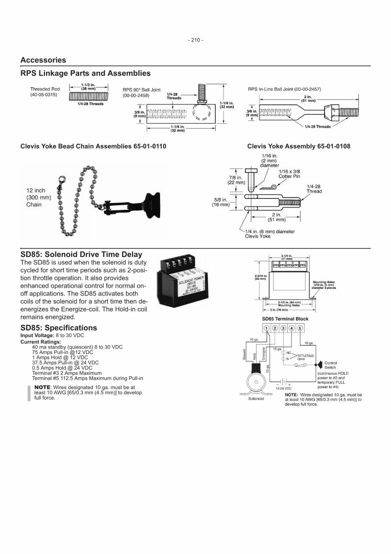
AccessoriesRPS Linkage Parts and Assemblies
Clevis Yoke Bead Chain Assemblies 65-01-0110 Clevis Yoke Assembly 65-01-0108
SD85: Solenoid Drive Time Delay The SD85 is used when the solenoid is duty cycled for short time periods such as 2-posi-tion throttle operation. It also provides enhanced operational control for normal on-off applications. The SD85 activates both coils of the solenoid for a short time then de- energizes the Energize-coil. The Hold-in coil remains energized.
SD85: Specifications Input Voltage: 8 to 30 VDC Current Ratings:
40 ma standby (quiescent) 8 to 30 VDC 75 Amps Pull-in @12 VDC 1 Amps Hold @ 12 VDC 37.5 Amps Pull-in @ 24 VDC 0.5 Amps Hold @ 24 VDC Terminal #3 2 Amps Maximum Terminal #5 112.5 Amps Maximum during Pull-in
NOTE: Wires designated 10 ga. must be at least 10 AWG [65/0.3 mm (4.5 mm)] to develop full force.
- 210 -
95028Revised 09-07
Section 40
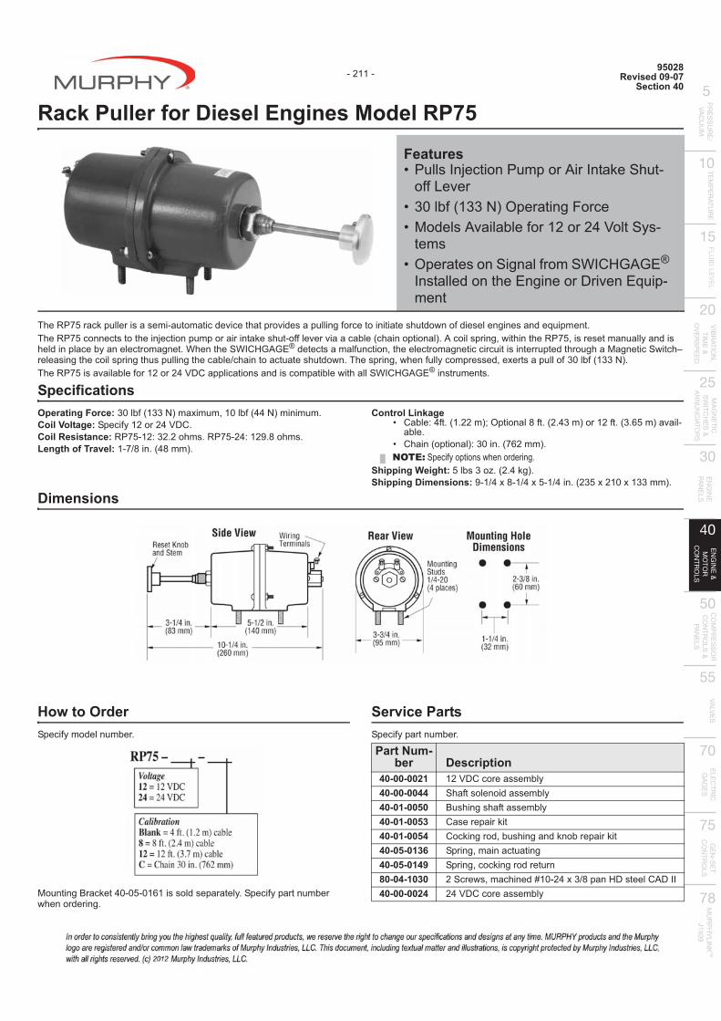
Rack Puller for Diesel Engines Model RP75
The RP75 rack puller is a semi-automatic device that provides a pulling force to initiate shutdown of diesel engines and equipment. The RP75 connects to the injection pump or air intake shut-off lever via a cable (chain optional). A coil spring, within the RP75, is reset manually and is held in place by an electromagnet. When the SWICHGAGE® detects a malfunction, the electromagnetic circuit is interrupted through a Magnetic Switch–releasing the coil spring thus pulling the cable/chain to actuate shutdown. The spring, when fully compressed, exerts a pull of 30 lbf (133 N). The RP75 is available for 12 or 24 VDC applications and is compatible with all SWICHGAGE® instruments.
Specifications Operating Force: 30 lbf (133 N) maximum, 10 lbf (44 N) minimum. Coil Voltage: Specify 12 or 24 VDC. Coil Resistance: RP75-12: 32.2 ohms. RP75-24: 129.8 ohms. Length of Travel: 1-7/8 in. (48 mm).
Control Linkage � ��!���?;@&>@''�*��������Q;@&'@?Z�*��>';@&Z@�V�*�=����
able. � �+���&�������*�ZJ��@&z�'��*@
Shipping Weight: 5 lbs 3 oz. (2.4 kg). Shipping Dimensions: 9-1/4 x 8-1/4 x 5-1/4 in. (235 x 210 x 133 mm).
Dimensions
How to Order Specify model number.
|������������?J�JV�J>�>� ��� ��������@�����;�������!��when ordering.
Service Parts Specify part number.
Features� ���� ������������or Air Intake Shut-
off Lever� ZJ�!;&>ZZ�*�������������� |���� �=����!��;��>'��'?<���� �
tems� ������ ��������;����}��]{�{�®
Installed on the Engine or Driven Equip-ment
NOTE: Specify options when ordering.
Part Num-ber Description
40-00-0021 12 VDC core assembly40-00-0044 Shaft solenoid assembly40-01-0050 Bushing shaft assembly40-01-0053 Case repair kit40-01-0054 Cocking rod, bushing and knob repair kit40-05-0136 Spring, main actuating40-05-0149 Spring, cocking rod return80-04-1030 2 Screws, machined #10-24 x 3/8 pan HD steel CAD II40-00-0024 24 VDC core assembly
- 211 -
Installation Instructions
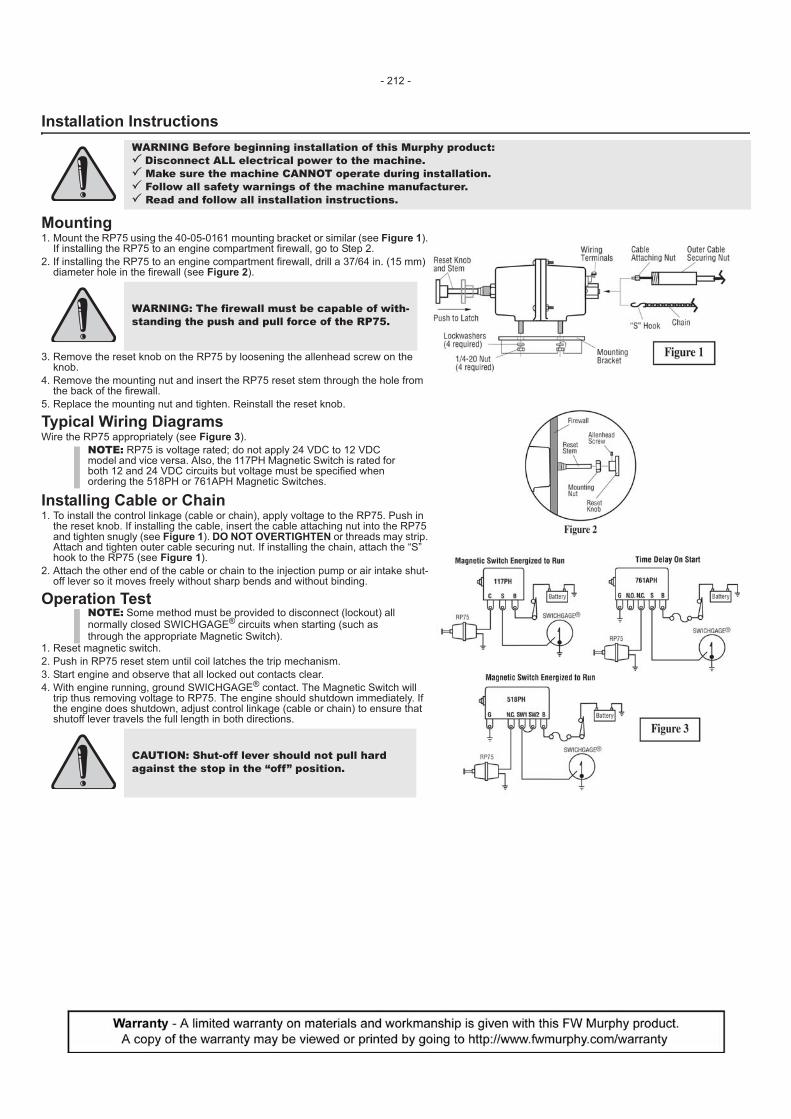
Mounting 1. Mount the RP75 using the 40-05-0161 mounting bracket or similar (see Figure 1).
If installing the RP75 to an engine compartment firewall, go to Step 2. 2. If installing the RP75 to an engine compartment firewall, drill a 37/64 in. (15 mm)
diameter hole in the firewall (see Figure 2).
3. Remove the reset knob on the RP75 by loosening the allenhead screw on the knob.
4. Remove the mounting nut and insert the RP75 reset stem through the hole from the back of the firewall.
5. Replace the mounting nut and tighten. Reinstall the reset knob.
Typical Wiring Diagrams Wire the RP75 appropriately (see Figure 3).
Installing Cable or Chain 1. To install the control linkage (cable or chain), apply voltage to the RP75. Push in
the reset knob. If installing the cable, insert the cable attaching nut into the RP75 and tighten snugly (see Figure 1). DO NOT OVERTIGHTEN or threads may strip. Attach and tighten outer cable securing nut. If installing the chain, attach the “S” hook to the RP75 (see Figure 1).
2. Attach the other end of the cable or chain to the injection pump or air intake shut-off lever so it moves freely without sharp bends and without binding.
Operation Test
1. Reset magnetic switch. 2. Push in RP75 reset stem until coil latches the trip mechanism. 3. Start engine and observe that all locked out contacts clear. 4. With engine running, ground SWICHGAGE® contact. The Magnetic Switch will
trip thus removing voltage to RP75. The engine should shutdown immediately. If the engine does shutdown, adjust control linkage (cable or chain) to ensure that shutoff lever travels the full length in both directions.
WARNING Before beginning installation of this Murphy product:� Disconnect ALL electrical power to the machine.� Make sure the machine CANNOT operate during installation.� Follow all safety warnings of the machine manufacturer.� Read and follow all installation instructions.
WARNING: The firewall must be capable of with-standing the push and pull force of the RP75.
NOTE: RP75 is voltage rated; do not apply 24 VDC to 12 VDC model and vice versa. Also, the 117PH Magnetic Switch is rated for both 12 and 24 VDC circuits but voltage must be specified when ordering the 518PH or 761APH Magnetic Switches.
NOTE: Some method must be provided to disconnect (lockout) all normally closed SWICHGAGE® circuits when starting (such as through the appropriate Magnetic Switch).
CAUTION: Shut-off lever should not pull hard against the stop in the “off” position.
- 212 -
04052Revised 04-04
Section 40
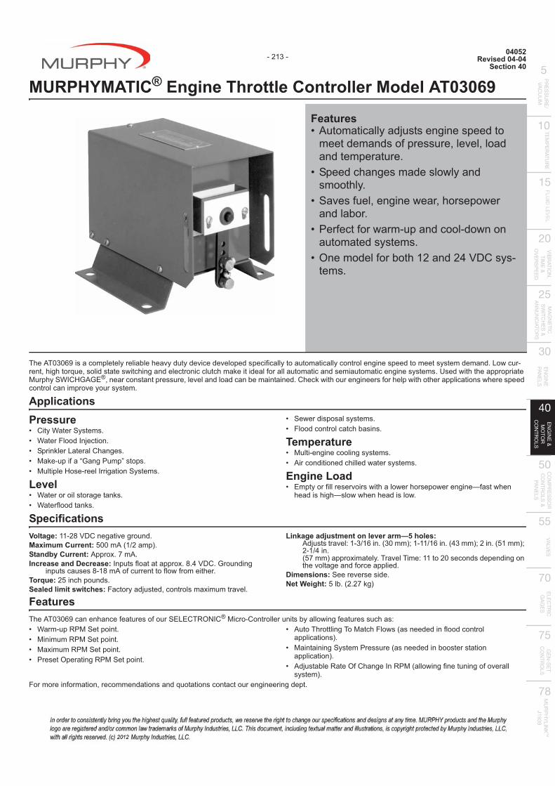
MURPHYMATIC® Engine Throttle Controller Model AT03069
The AT03069 is a completely reliable heavy duty device developed specifically to automatically control engine speed to meet system demand. Low cur-rent, high torque, solid state switching and electronic clutch make it ideal for all automatic and semiautomatic engine systems. Used with the appropriate Murphy SWICHGAGE®, near constant pressure, level and load can be maintained. Check with our engineers for help with other applications where speed control can improve your system.
Applications Pressure � ���}����� �� @� }����������������@� ���������"������+���� @� |�������;��{�������� �� @� |������]� ����������������� �� @
Level � }�������� �������� @� }���;������� @
� ��%���� �� �� � �� @� ��������������+!� �� @
Temperature � |����������������� � �� @� ��������������+�����%��� � �� @
Engine Load � ������;����� ��=��� %�+a lower horsepower engine—fast when
head is high—slow when head is low.
Specifications Voltage: 11-28 VDC negative ground. Maximum Current: 500 mA (1/2 amp). Standby Current: Approx. 7 mA. Increase and Decrease: Inputs float at approx. 8.4 VDC. Grounding
inputs causes 8-18 mA of current to flow from either. Torque: 25 inch pounds. Sealed limit switches:���������� ��~������ ��\������=��@
Linkage adjustment on lever arm—5 holes: ���� ��=���>�Z`>���@&ZJ��*�>�>>`>���@&?Z��*�'��@&V>��*�2-1/4 in. &Vz��*�����\������@#��=��#����>>�'J ����� �����������the voltage and force applied.
Dimensions: See reverse side. Net Weight: 5 lb. (2.27 kg)
Features The AT03069 can enhance features of our SELECTRONIC®|����������������� !�����%���;����� ��+� �� }��������|������@� |��������|������@� |�\������|������@� ��� �����������|������@
� ���#+������#�|��+���% &� ��������;����������applications).
� |����������� ����� ���&� ��������!�� �� ����application).
� ���� �!������;�+��������|(allowing fine tuning of overall system).
���������;�������~������������� and quotations contact our engineering dept.
Features� ��������������� ������ �����
meet demands of pressure, level, load and temperature.
� ������+���� made slowly and smoothly.
� ��=� ;���~������%���~+�� ���%��and labor.
� ���;��;��%����������������%���automated systems.
� ��������;��!�+>'���'?<$� � �tems.
- 213 -
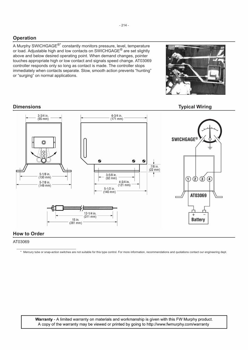
Operation A Murphy SWICHGAGE®* constantly monitors pressure, level, temperature or load. Adjustable high and low contacts on SWICHGAGE® are set slightly above and below desired operating point. When demand changes, pointer touches appropriate high or low contact and signals speed change. AT03069 controller responds only so long as contact is made. The controller stops immediately when contacts separate. Slow, smooth action prevents “hunting” or “surging” on normal applications.
Dimensions Typical Wiring
How to Order AT03069
* Mercury tube or snap-action switches are not suitable for this type control. For more information, recommendations and quotations contact our engineering dept.
- 214 -

01035Revised 10-04
Section 40
Electric Motor Driven Clutch Operator for Engine Automation Systems
The CO3 is an electrically controlled and driven actuator for automatic operation of two position, lever action equipment. Primarily designed to engage and disengage over-center clutches on engines, the CO3 has a wide variety of applications such as opening and closing of pipeline valves, engagement and disengagement of pumps, fixture positioning in automated process control, etc. The positive action screw-type actuator is fully adjustable for length of stroke up to 6 inches (152 mm). The CO3 motor is equipped with an overload clutch that slips if overloaded. In addition, the motor is protected with an automatic reset thermal overload. The CO3 is available for 12 or 24 VDC applications and is compatible with MURPHYMATIC® start-stop engine control-lers.
Applications � ������$� �����+� � ����;���������<��=�
� ����� � #%��� ����"�=���������_������
Specifications Voltage:
CO3-12: 12 VDC, negative ground. CO3-24: 24 VDC, negative ground.
Travel (adjustable): 6 in. (152 mm) max. Case Material: Cast aluminum. Built-in Circuit Breaker: 20 A. Operating Force:
CO3-12: 250 lb-f (1112N) max.CO3-24: 500 lb-f (2224N) max.
Duty Cycle @ 77°F (25°C): CO3-12: 40% max. @ 125 lb-f (556N) to 25% @ 250 lb-f (1112N). CO3-24: 100% max. @ 75 lb-f (334N) to 25% @ 500 lb-f (2224N).
Speed: CO3-12: 1.2 in./sec (3 cm/sec.) @ 0 lb-f to 1.00 in./sec. (1 cm/sec.) @ 250 lb-f (1112N). CO3-24: 2.4 in./sec (6 cm/sec.) @ 0 lb-f to 1.35 in./sec. (3 cm/sec.) @ 500 lb-f (2224N).
Drive:���;����������|� ���%@Current:
CO3-12: 20 amp max. CO3-24: 14 amp max.
Operating Temperature: -15 to 150°F (-26 to 66°C). Shipping Weight: 40 lb (18.1 kg). Shipping Dimensions: 25 x 14-1/2 x 12 in. (635 x 368 x 305 mm).
Basic Operation Refer to Figure 4 on back page. When the CO3 receives a signal to engage, the heavy-duty DC motor operates to extend the actuator shaft and yoke a predetermine�����+@"���+�;extension is controlled by the adjustable cams in the control housing. When disengaging, the motor reverses and retracts the actuator shaft. At engage-ment end of the stroke, the actuator backs off from its maximum travel to relieve pressure on the clutch or other device.
Dimensions How to Order For 12 VDC applications specify CO3-12. For 24 VDC applications specify CO3-24.
Features� ������ ���$� ������ ����+� 'VJ�!�;&>>>'�*��VJJ�!�;&'''?�*
Operating Force� ������!��%�+|[��]ª|�#��®
��������������� � |���� �=����!��;��>'��'?<���� �
tems� #%��ª���"�����}������� ���� �!�������
- 215 -
Installation Instructions
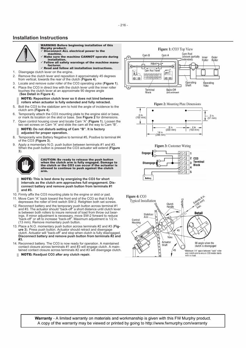
1. Disengage clutch lever on the engine.2. Remove the clutch lever and reposition it approximately 45 degrees
from vertical, towards the rear of the clutch (Figure 4).3. Locate and remove outer roller of the CO3 operating yoke (Figure 1).4. Place the CO3 in direct line with the clutch lever until the inner roller
touches the clutch lever at an approximate 90 degree angle (See Detail in Figure 4).
5. Bolt the CO3 to the stabilizer arm to hold the angle of incidence to the clutch arm (Figure 4).
6. Temporarily attach the CO3 mounting plate to the engine skid or base, or mark its location on the skid or base. See Figure 2 for dimensions.
7. Open control housing cover and locate Cam “A” (Figure 1). Loosen the two set screws on Cam “A” and slide the cam all the way to Cam “B”.
8. Temporarily wire Battery Negative to terminal #5, Positive to terminal #4 of the CO3 (Figure 3).
9. Apply a momentary N.O. push button between terminals #1 and #3. When the push button is pressed the CO3 actuator will extend (Figure 3).
10. Firmly affix the CO3 mounting plate to the engine or skid or pad. 11. Move Cam “A” back toward the front end of the CO3 so that it fully
depresses the roller of limit switch SW-2. Retighten both set screws.12. Reconnect battery and the temporary push button across terminal #1
and #3. The actuator should “back-off” a short distance until clutch lever is between both rollers to insure removal of load from throw out bear-ings. If minor adjustment is necessary, move SW-2 forward to reduce “back-off” or aft to increase “back-off”. Maximum adjustment is 1/2 in. (13 mm). Remove momentary push button.
13. Place a N.O. momentary push button across terminals #2 and #3 (Fig-ure 3). Press push button. Actuator should retract and disengage clutch. Actuator will “back-off” and stop when clutch is fully disengaged. Disconnect battery and remove push button from terminals #2 and #3.
14. Reconnect battery. The CO3 is now ready for operation. A maintained contact closure across terminals #1 and #3 will engage clutch. A main-tained contact closure across terminals #2 and #3 will disengage clutch.
WARNING Before beginning installation of this Murphy product:� Disconnect ALL electrical power to the
machine.� Make sure the machine CANNOT operate during
installation.� Follow all safety warnings of the machine manu-
facturer.� Read and follow all installation instructions.
NOTE: Reposition clutch lever so it does not bind between rollers when actuator is fully extended and fully retracted.
NOTE: Do not disturb setting of Cam “B”. It is factory adjusted for proper operation.
CAUTION: Be ready to release the push button when the clutch arm is fully engaged. Damage to the clutch or the CO3 can occur if the actuator is allowed to continue to push against the clutch arm.
NOTE: This is best done by energizing the CO3 for short intervals as the clutch arm approaches full engagement. Dis-connect battery and remove push button from terminals #1 and #3.
NOTE: Readjust CO3 after any clutch repair.
- 216 -
0910462Revised 09-05
Section 40
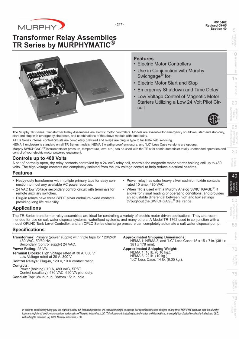
Transformer Relay Assemblies TR Series by MURPHYMATIC®
The Murphy TR Series, Transformer Relay Assemblies are electric motor controllers. Models are available for emergency shutdown, start and stop only, start and stop with emergency shutdown, and combinations of the above models with time delay.All TR Series internal control circuits are completely prewired and relays are plug in type to facilitate field servicing.NEMA 1 enclosure is standard on all TR Series models. NEMA 3 weatherproof enclosure, and “LC” Less Case versions are optional.
® instruments for pressure, temperature, level etc., can be used with the TR’s for semiautomatic or totally unattended operation and control of your electric motor powered equipment.
Controls up to 480 VoltsA set of normally open, dry relay contacts controlled by a 24 VAC relay coil, controls the magnetic motor starter holding coil up to 480 volts. The high voltage contacts are completely isolated from the low voltage control to help reduce electrical hazards.
Features� ]��=�������� ;�����%�+���������������� ;���� �����
nection to most any available AC power sources.� '?<����%<����� ��������������������%�+������� ;��
remote auxiliary switches.� ������������ +�=�+�����$# ��=����������\��������
providing long life reliability.
� ��%�������+� �\��+��=� ��=����������\�������� rated 10 amp, 480 VAC.
�allows for visual reading of operating conditions, and provides an adjustable differential between high and low settings
ApplicationsThe TR Series transformer relay assemblies are ideal for controlling a variety of electric motor driven applications. They are ������mended for use on salt water disposal system ~%���;���� � �� ~��������+�� @�|����#��>z�'� ��������������%�+��������"]�#���"�=�����������~�������"������ �� �+����pressure can completely automate a salt water disposal pump.
SpecificationsTransformer:�������&��%�� �����*%�+������� ;��>'J`'?J`
?QJ<��@VJ`�J]^@���������&������ �����*'?<��@
Power Rating: 25 VA.Terminal Blocks:]��+<����������ZJ�~�JJ<@
Low Voltage rated at 20 A, 300 V.Control Relays:�������~>'J<~>J�����������@Contacts:
��%��&+������*�>J�~?QJ<��~���#@������&��\������*�?QJ<��~��J<��������@
Conduit:#���Z`?��@+�!�����>`'��@+���@
Approximated Shipping Dimensions:��|�>���|�Z�����"��"� �� ��>V\>V\z��@&ZQ>\ZQ>\>zQ��*@
Approximated Shipping Weight:��|�>�>Q�!@&Q@>���@*@��|�Z�''�!@&>J��@*@�"��"� �� ��>?�!@&�@ZV��@*@
Features� �������|������������ � [ �������������%�+|���+�
Swichgage®;���� �������|������������� ����������+���%����#���$����� "�%<������������;|������|���
����� [���^����"�%'?<����������cuit
- 217 -
Murphy SWICHGAGE
®}+��#�� � ��%�+�|���+��������}��]{�{�~�
®throughout the SWICHGAGE dial range.
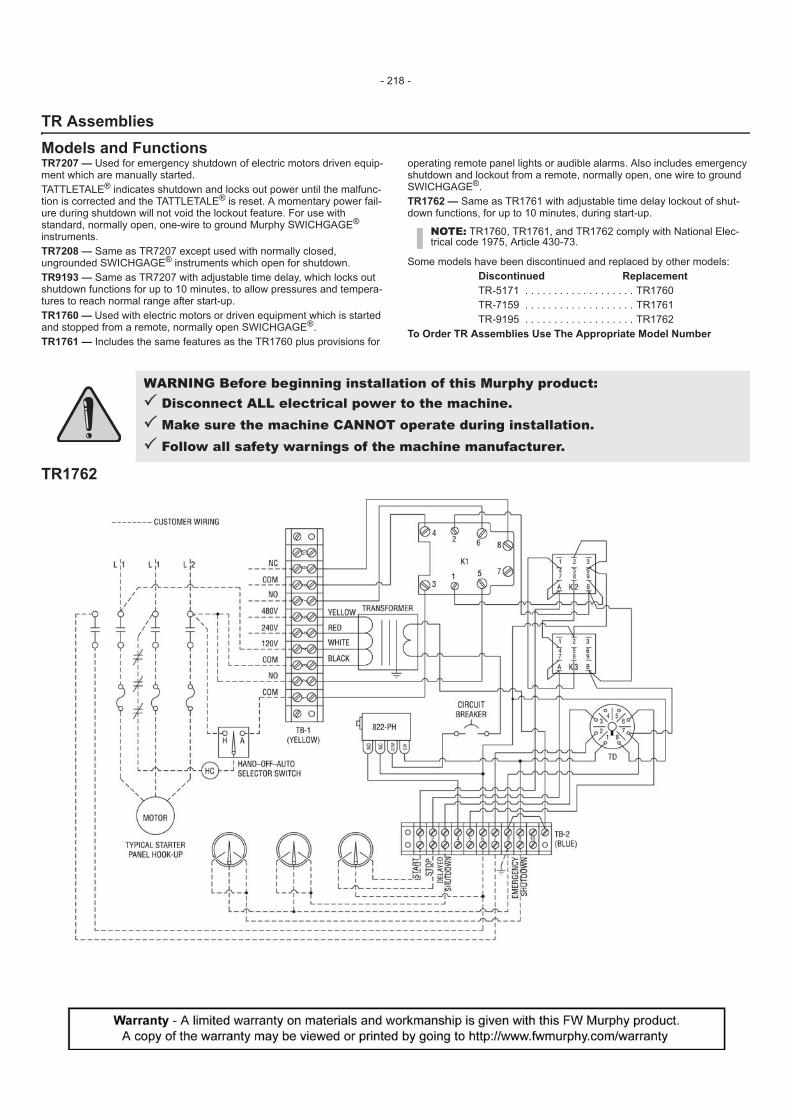
TR AssembliesModels and FunctionsTR7207 — Used for emergency shutdown of electric motors driven equip-ment which are manually started.TATTLETALE® indicates shutdown and locks out power until the malfunc-tion is corrected and the TATTLETALE® is reset. A momentary power fail-ure during shutdown will not void the lockout feature. For use with standard, normally open, one-wire to ground Murphy SWICHGAGE® instruments.TR7208 — Same as TR7207 except used with normally closed, ungrounded SWICHGAGE® instruments which open for shutdown.TR9193 — Same as TR7207 with adjustable time delay, which locks out shutdown functions for up to 10 minutes, to allow pressures and tempera-tures to reach normal range after start-up.TR1760 — Used with electric motors or driven equipment which is started and stopped from a remote, normally open SWICHGAGE®.TR1761 — Includes the same features as the TR1760 plus provisions for
operating remote panel lights or audible alarms. Also includes emergency shutdown and lockout from a remote, normally open, one wire to ground SWICHGAGE®.TR1762 — Same as TR1761 with adjustable time delay lockout of shut-down functions, for up to 10 minutes, during start-up.
Some models have been discontinued and replaced by other models:Discontinued ReplacementTR-5171 . . . . . . . . . . . . . . . . . . . TR1760TR-7159 . . . . . . . . . . . . . . . . . . . TR1761TR-9195 . . . . . . . . . . . . . . . . . . . TR1762
To Order TR Assemblies Use The Appropriate Model Number
TR1762
NOTE: TR1760, TR1761, and TR1762 comply with National Elec-trical code 1975, Article 430-73.
WARNING Before beginning installation of this Murphy product:� Disconnect ALL electrical power to the machine.� Make sure the machine CANNOT operate during installation.� Follow all safety warnings of the machine manufacturer.
- 218 -
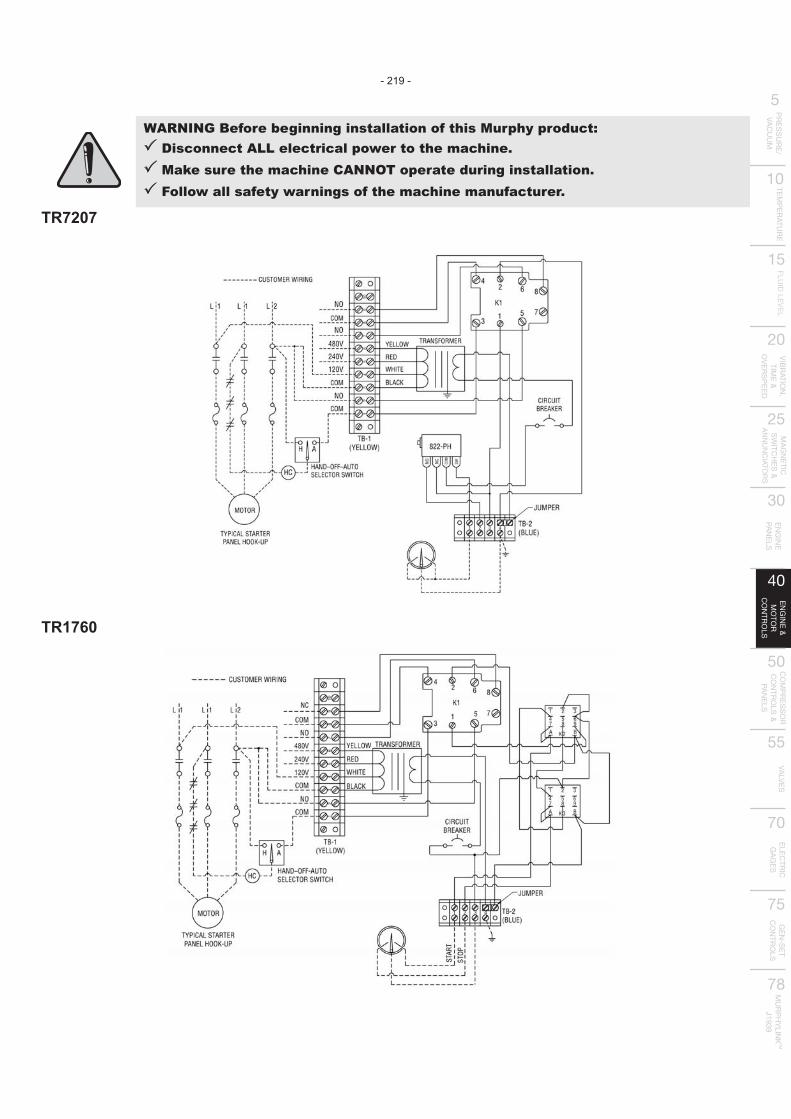
TR7207
TR1760
WARNING Before beginning installation of this Murphy product:� Disconnect ALL electrical power to the machine.� Make sure the machine CANNOT operate during installation.� Follow all safety warnings of the machine manufacturer.
- 219 -
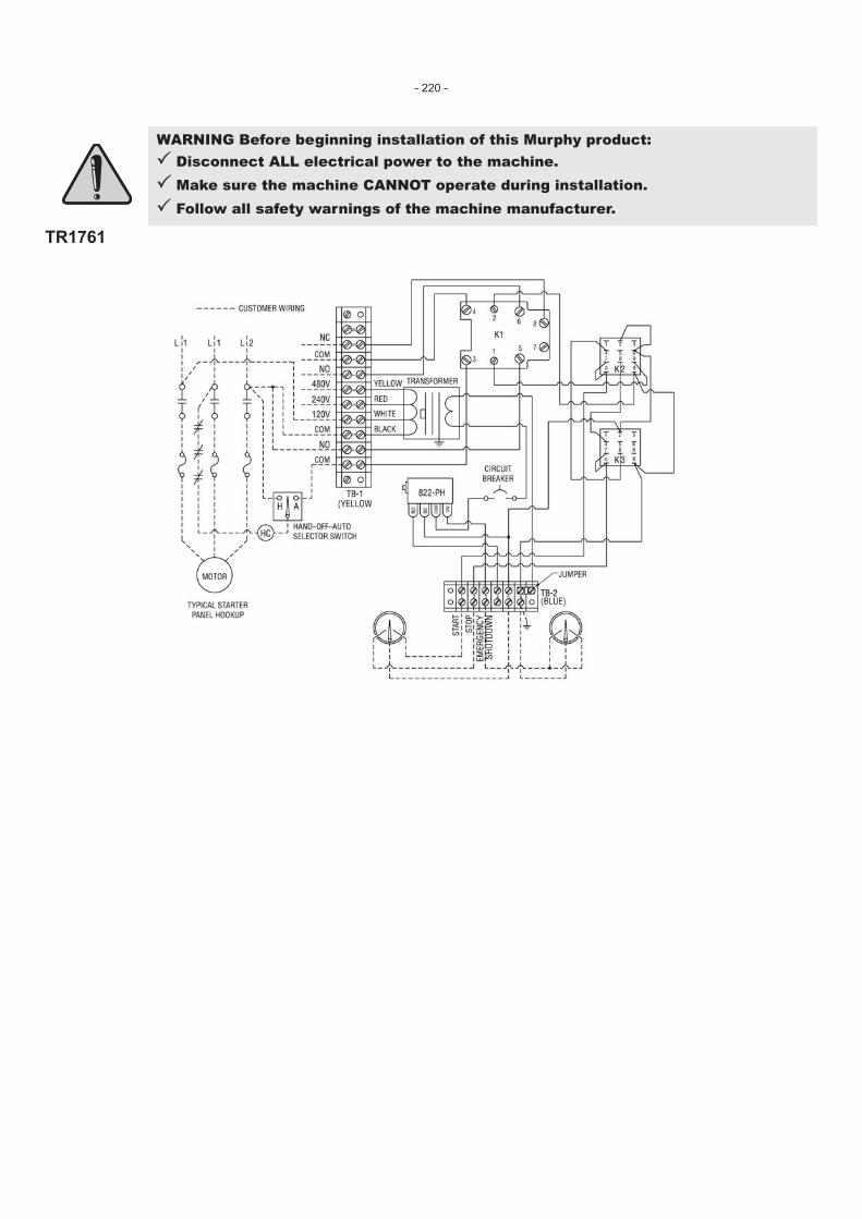
TR1761
WARNING Before beginning installation of this Murphy product:� Disconnect ALL electrical power to the machine.� Make sure the machine CANNOT operate during installation.� Follow all safety warnings of the machine manufacturer.
- 220 -
091047407-15-10
Section 40
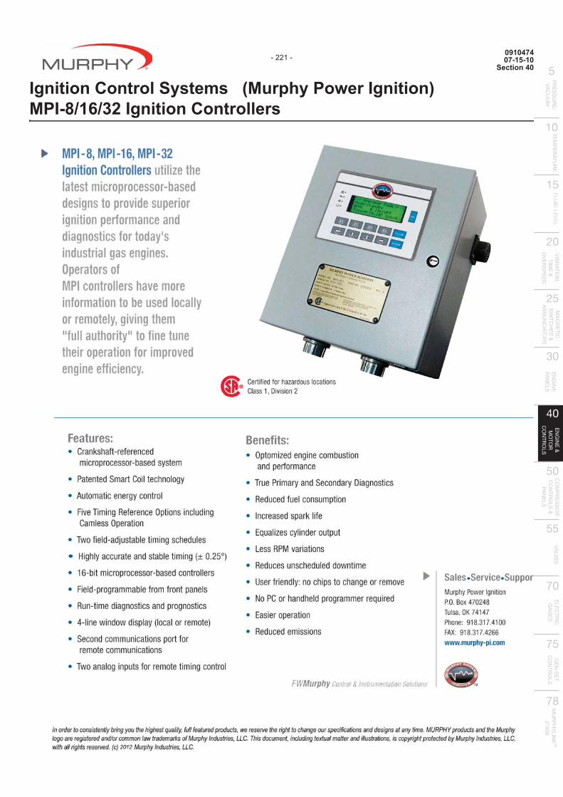
Ignition Control Systems (Murphy Power Ignition)MPI-8/16/32 Ignition Controllers
- 221 -
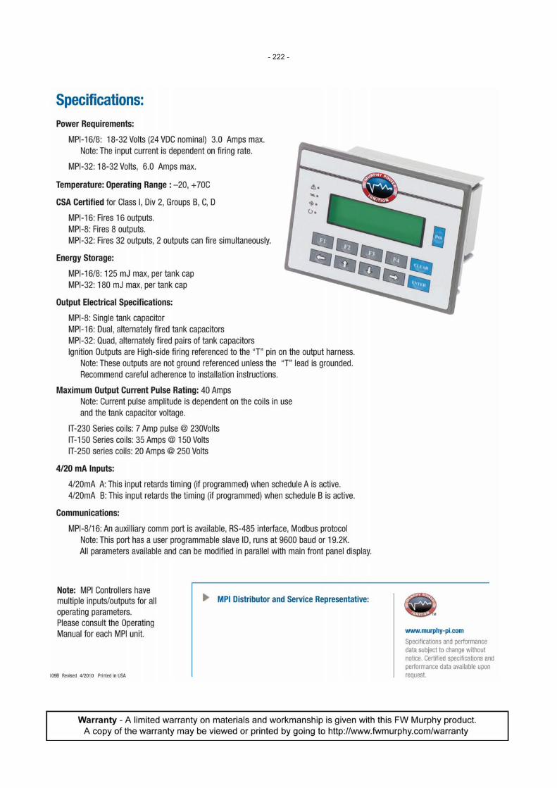
- 222 -
091051707-15-10
Section 40
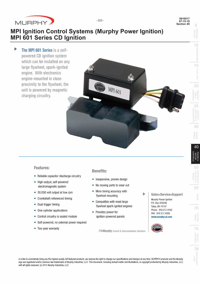
MPI Ignition Control Systems (Murphy Power Ignition)MPI 601 Series CD Ignition
- 223 -
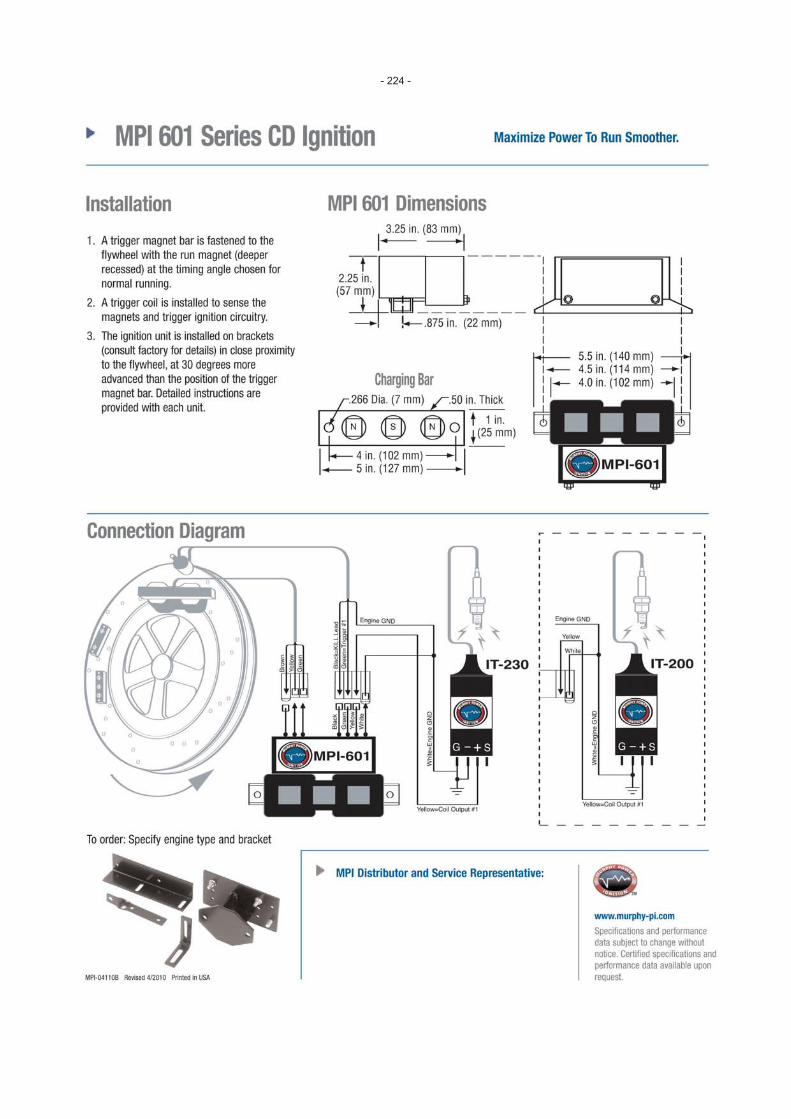
- 224 -

091051507-15-10
Section 40
MPI Detonation Sensing Interface System - Model DSI
- 225 -

- 226 -

091051407-15-10
Section 40
Power Supply (Murphy Power Ignition)MPI Brushless Alternators
- 227 -
- 228 -
091051307-15-10
Section 40
MPI Ignition Control Systems (Murphy Power Ignition)MPI Ignition Coils
- 229 -
- 230 -

091047607-15-10
Section 40
Air Fuel Ratio Controls (Compliance Controls)AFR-1R - Rich Burn Air-Fuel Ratio Controller
- 231 -
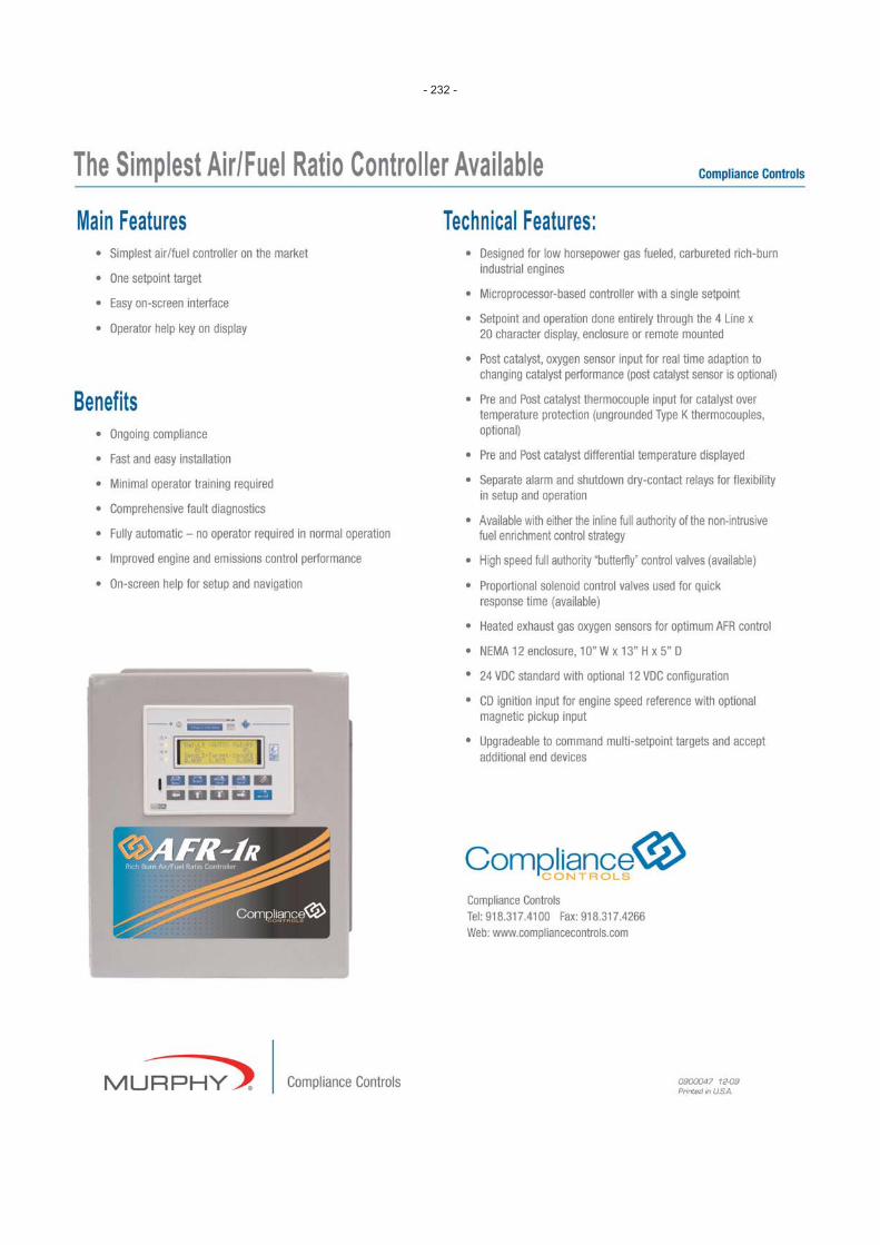
- 232 -

091047707-15-10
Section 40
Air Fuel Ratio Controls (Compliance Controls)AFR-9R - Multipoint Air-Fuel Ratio Controller
- 233 -

- 234 -

091047507-15-10
Section 40
Air Fuel Ratio Controls (Compliance Controls)AFR-64R — Rich-Burn Air-Fuel Control System
- 235 -

- 236 -

091049101-26-10
Section 40
Air Fuel Ratio Controls (Compliance Controls)AFR-64L — Lean-Burn Air-Fuel Control System
- 237 -
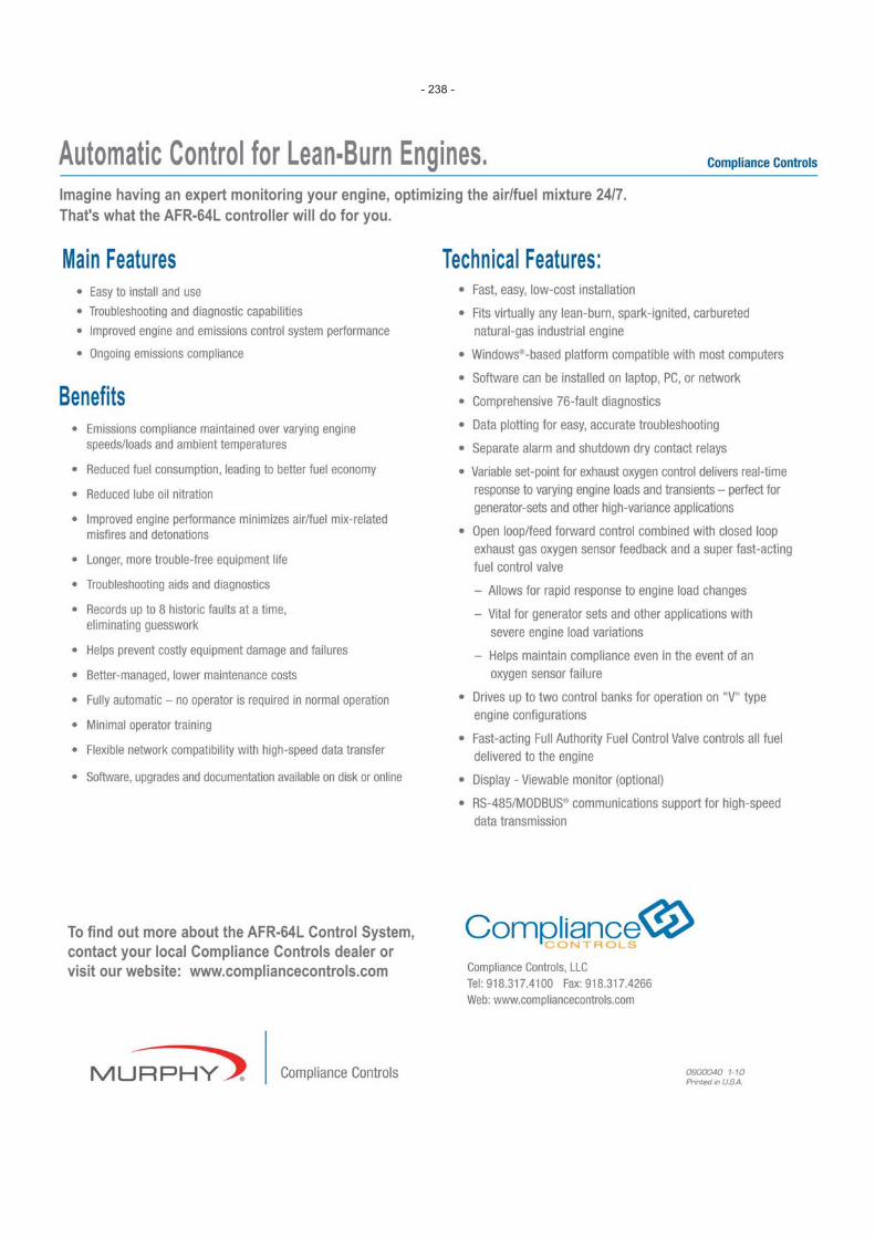
- 238 -
091047807-15-10
Section 40
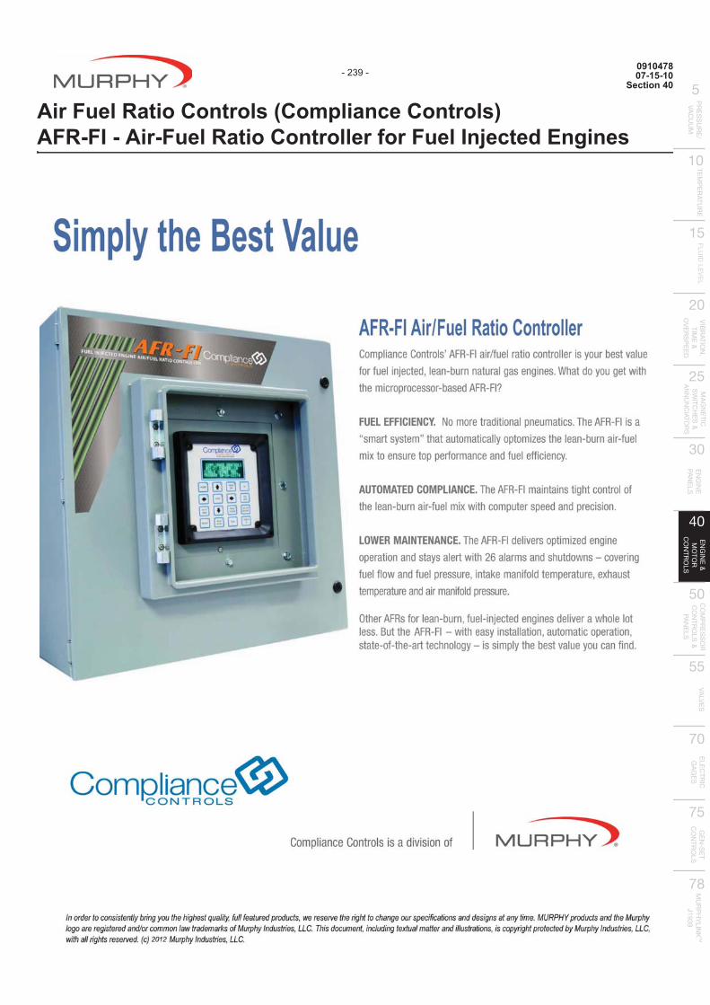
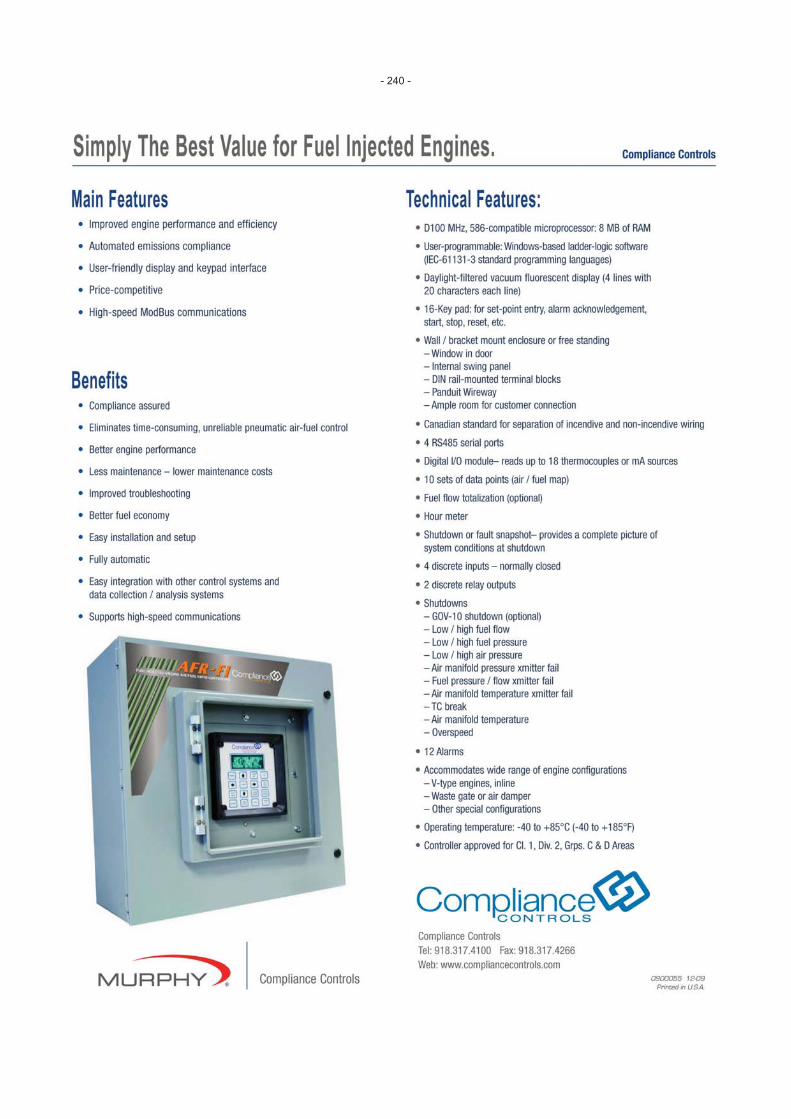
Air Fuel Ratio Controls (Compliance Controls)AFR-FI - Air-Fuel Ratio Controller for Fuel Injected Engines
- 239 -
- 240 -

101067001-17-12
Section 40
EICS - Engine Integrated Control System - (Compliance Controls)
Features� ����|�������+����;������������������ #%�������� �=����!������;�������`�;;��������������~
���������� ��� �������&������� ����� *� ������~+�����������;������ ��$�������~���`;���
������~��������������=������ ����������� ��������!������������ ��;������ ����;��������
������ ��=��������������;��������� � ��� "��+����;� �� ��� �������� ����`����=�������
���;���_������+���� � |��� ��������������� ;���\������������������ �� � {���+���������� ������;���� $�� +�����=��|��!� ��?QV� $���������
�����^�������������� ���;����������������������� �������������� �� ���+���=��%�+|���+�� ��%���������������������� ��&����*@#+��������!��� ���������� �����������������������������������!���� ����;������;�����������������@�������!��� ����������� �������� � ��&��%����!�|��*~����;���������~ ������=������~����;������������� �� ~ �� �� ~+���� ���~����� ������������������&��[*�������������~ �=������������������+��� � ������%�++��� ���������� ����; �������������������� @#+�����+� !����������;������;���������=�������~�� ���������������%����������������;�������%�+��+�����;��������;�������� ��� @� $����=��=����������� %���=������� ��;�������� ������� ����`���������~�����������;;�������%�+����;����%�����+������;���=��+����+� �� ��;���������� @���������~+������������� +�����;������ ��=� � !�������������� ��� � �=�����������������@}�+����������!����������� ��%����� ��_������ ���~���������� ���~%�+��+�����;������ ��������������@
Benefits� �������� � ��« �����;����� ���������������� ������
��������
� #+����������������+���� ������=����������� �� �� �!��
� ������ ����;�������!�\� ������ ������ ����;��
� �������������������� ��������!����
� �����^�����;����������� ���;�������
� |������ ��� ��� ����������!�%���� �������%����������� ���
� �������� ������;������ ����������� ���������+����
� ������ ������;������������ �����
� ������ �� � ������%�++�������� ��������
- 241 -
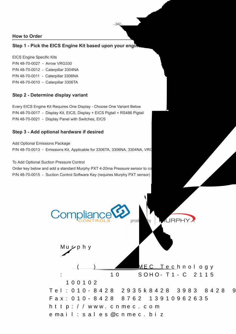
How to Order
Step 1 - Pick the EICS Engine Kit based upon your engine model
EICS Engine Specific KitsP/N 48-70-0027 - Arrow VRG330P/N 48-70-0012 - Caterpillar 3304NAP/N 48-70-0011 - Caterpillar 3306NAP/N 48-70-0010 - Caterpillar 3306TA
Step 2 - Determine display variant
Every EICS Engine Kit Requires One Display - Choose One Variant BelowP/N 48-70-0017 - Display Kit, EICS, Display + EICS Pigtail + RS486 PigtailP/N 48-70-0021 - Display Panel with Switches, EICS
Step 3 - Add optional hardware if desired
Add Optional Emissions PackageP/N 48-70-0013 - Emissions Kit, Applicable for 3306TA, 3306NA, 3304NA, VRG330
To Add Optional Suction Pressure ControlOrder key below and add a standard Murphy PXT 4-20ma Pressure sensor to completeP/N 48-70-0015 - Suction Control Software Key (requires Murphy PXT sensor)
- 242 -
美国Murphy摩菲经销商
联系我们:
信德迈科技(北京)有限公司 CNMEC Technology
地址:北京朝阳区望京街10号望京SOHO-T1-C座2115室
邮编:100102
Tel:010-8428 2935,8428 3983;8428 9077
Fax:010-8428 8762 13910962635
http://www.cnmec.com
email:[email protected]


![Electric Motor Controls Tutorial[1]](https://static.fdocuments.in/doc/165x107/577d258c1a28ab4e1e9f134c/electric-motor-controls-tutorial1.jpg)