Section 4 Fully Vented System - npstag.com · A fully vent modified sanitary plumbing system...
39
STUDENT NOTES CPCPSN4011A Plan, size and layout sanitary pipe work and fixtures © 2012 TAFE NSW Section 4-1 4. SANITARY PLUMBING FULLY VENTED SYSTEM On completion of this module, the student should be able to: Design, install and develop bills of quantities for a fully vented modified system for commercial and industrial premises of over SIX (6) floor levels or more. Assessment Criteria 4.1 Describe and design fully vented sanitary plumbing systems for commercial and industrial premises to meet the requirements of the Building Code of Australia, Plumbing Code of Australia and AS/NZS 3500. 4.2 Describe, design, install and develop bills of quantities for fully vented modified sanitary plumbing systems for domestic, commercial and industrial premises to meet the requirements of the Building Code of Australia, Plumbing Code of Australia and AS/NZS 3500. 4.3 Interpret various designs of sanitary plumbing systems for commercial and industrial premises of over SIX (6) floor levels and develop bills of quantities for these designs. Assessment Method may include • Written assessment based on assessment criteria. • Practical activities based on assessment criteria. • Designs based on assessment criteria. • Assignment based on assessment criteria
Transcript of Section 4 Fully Vented System - npstag.com · A fully vent modified sanitary plumbing system...

STUDENT NOTES CPCPSN4011A Plan, size and layout sanitary pipe work and fixtures
© 2012 TAFE NSW Section 4-1
4. SANITARY PLUMBING FULLY VENTED SYSTEM On completion of this module, the student should be able to: Design, install and develop bills of quantities for a fully vented modified system for commercial and industrial premises of over SIX (6) floor levels or more.
Assessment Criteria 4.1 Describe and design fully vented sanitary plumbing systems for commercial
and industrial premises to meet the requirements of the Building Code of Australia, Plumbing Code of Australia and AS/NZS 3500.
4.2 Describe, design, install and develop bills of quantities for fully vented
modified sanitary plumbing systems for domestic, commercial and industrial premises to meet the requirements of the Building Code of Australia, Plumbing Code of Australia and AS/NZS 3500.
4.3 Interpret various designs of sanitary plumbing systems for commercial and
industrial premises of over SIX (6) floor levels and develop bills of quantities for these designs.
Assessment Method may include
• Written assessment based on assessment criteria.
• Practical activities based on assessment criteria.
• Designs based on assessment criteria.
• Assignment based on assessment criteria
STUDENT NOTES CPCPSN4011A Plan, size and layout sanitary pipe work and fixtures
© 2012 TAFE NSW Section 4-2
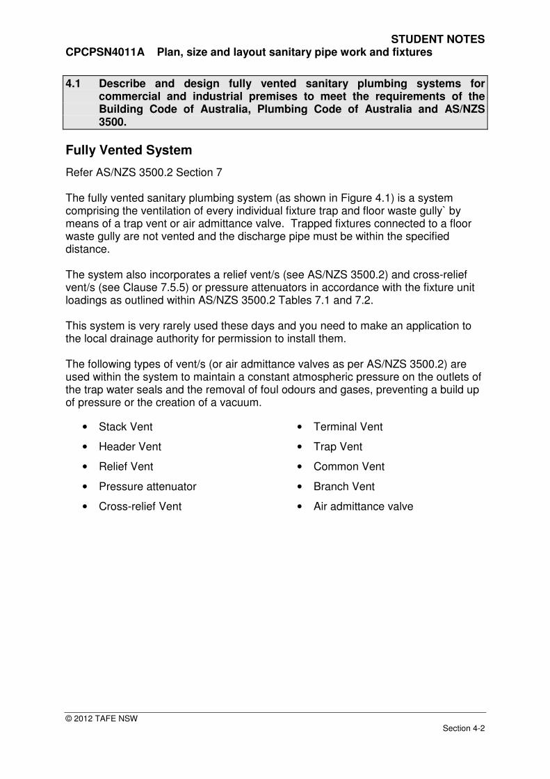
4.1 Describe and design fully vented sanitary plumbing systems for commercial and industrial premises to meet the requirements of the Building Code of Australia, Plumbing Code of Australia and AS/NZS 3500.
Fully Vented System
Refer AS/NZS 3500.2 Section 7 The fully vented sanitary plumbing system (as shown in Figure 4.1) is a system comprising the ventilation of every individual fixture trap and floor waste gully` by means of a trap vent or air admittance valve. Trapped fixtures connected to a floor waste gully are not vented and the discharge pipe must be within the specified distance. The system also incorporates a relief vent/s (see AS/NZS 3500.2) and cross-relief vent/s (see Clause 7.5.5) or pressure attenuators in accordance with the fixture unit loadings as outlined within AS/NZS 3500.2 Tables 7.1 and 7.2. This system is very rarely used these days and you need to make an application to the local drainage authority for permission to install them. The following types of vent/s (or air admittance valves as per AS/NZS 3500.2) are used within the system to maintain a constant atmospheric pressure on the outlets of the trap water seals and the removal of foul odours and gases, preventing a build up of pressure or the creation of a vacuum.
• Stack Vent
• Header Vent
• Relief Vent
• Pressure attenuator
• Cross-relief Vent
• Terminal Vent
• Trap Vent
• Common Vent
• Branch Vent
• Air admittance valve

STUDENT NOTES CPCPSN4011A Plan, size and layout sanitary pipe work and fixtures
© 2012 TAFE NSW Section 4-3
Stack
Sanitary Drainage
Stack Vent
Header Vent
Fixture Pair
Relief Vent
Stack
FW
Indirect Connected Fixture
Fixtures Back to Back
Common Vent
Relief Vent
Stack Vent
Trap Vent
Cross Vent
Relief Vent
Common Discharge Pipe
Group Vent
Group Vent
Fixture Discharge Pipe
Fixture Discharge Pipe
Fixture Discharge Pipe
Trap Vent
Fixture Discharge Pipe
Gully
Branch Drain
Trap Vent
Terminal Vent
Fixture Discharge Pipe
Common Discharge Pipe
Fig. 4.1 Fully Vented System
NOT TO SCALE

STUDENT NOTES CPCPSN4011A Plan, size and layout sanitary pipe work and fixtures
© 2012 TAFE NSW Section 4-4
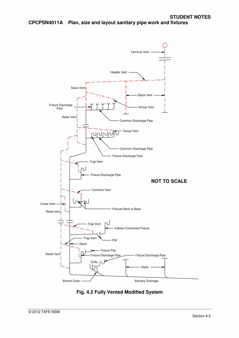
Fully Vented Modified System
Refer AS/NZS 3500.2. This section outlines the design requirements and installation methods for the fully vented and fully vented modified systems of sanitary plumbing. Students are encouraged to read AS/NZS 3500.2 Section 7. A fully vent modified sanitary plumbing system differs from the Fully Vented System. Individual fixture trap vents or air admittance valves are omitted and two or more fixtures discharging to the same common graded discharge pipe or branch are vented by means of one or more group and or branch vent/s or air admittance valve/s as shown in figure 4.2. Every graded discharge pipe connected to the stack must be vented by at least one vent or air admittance valve except the uppermost branch to the stack providing it is within distance. The following types of vent/s (or air admittance valves as per AS/NZS 3500.2) are used within the system to maintain a constant atmospheric pressure on the outlets of the trap water seals and the removal of foul odours and gases, preventing a build up of pressure or the creation of a vacuum.
• Stack Vent
• Header Vent
• Relief Vent
• Pressure attenuator
• Cross-relief Vent
• Terminal Vent
• Trap Vent
• Common Vent
• Branch Vent
• Air admittance valve
Sizing of Stack The size of the stack is determined by the fixture unit loading of all the fixtures connected to it and the developed length of its vent.
Develop Length
Refer AS/NZS 3500.2
The develop length of a stack vent is:
a) for stacks with relief vents, the length of the relief vent; or
b) for stacks without relief vents, the length of the stack vent and the stack
to the point of connection of the lowest branch.
STUDENT NOTES CPCPSN4011A Plan, size and layout sanitary pipe work and fixtures
© 2012 TAFE NSW Section 4-5
Stack
Sanitary Drainage
Stack Vent
Header Vent
Fixture Pair
Relief Vent
Stack
FW
Indirect Connected Fixture
Fixtures Back to Back
Common Vent
Relief Vent
Stack Vent
Trap Vent
Cross Vent
Relief Vent
Common Discharge Pipe
Group Vent
Group Vent
Fixture Discharge Pipe
Fixture Discharge Pipe
Fixture Discharge Pipe
Trap Vent
Fixture Discharge Pipe
Gully
Branch Drain
Trap Vent
Terminal Vent
Fixture Discharge Pipe
Common Discharge Pipe
Fig. 4.2 Fully Vented Modified System
NOT TO SCALE

STUDENT NOTES CPCPSN4011A Plan, size and layout sanitary pipe work and fixtures
© 2012 TAFE NSW Section 4-6
METHOD OF CALCULATION FOR STACK SIZE a) Calculate the total number of fixture units from all fixtures connected to the
stack as given within AS/NZS 3500.2 Table 6.1 b) Size the stack according to:
i) Table 7.2 (a) for stacks of 4 or more floor levels;
ii) Table 7.2 (b) for stacks three or fewer floor levels.
Using AS/NZS3500.2 students are to complete the table below
TABLE 7.2 MAXIMUM LOADING ON STACKS IN FIXTURE UNITS
Size of stack DN
Maximum loading per floor level
Maximum loading per stack
(a) Four or more floor levels
40
50
65
80
100
125
150
225
(b) Three or fewer floor levels
40
50
65
80
100
125
150
225
STUDENT NOTES CPCPSN4011A Plan, size and layout sanitary pipe work and fixtures
© 2012 TAFE NSW Section 4-7
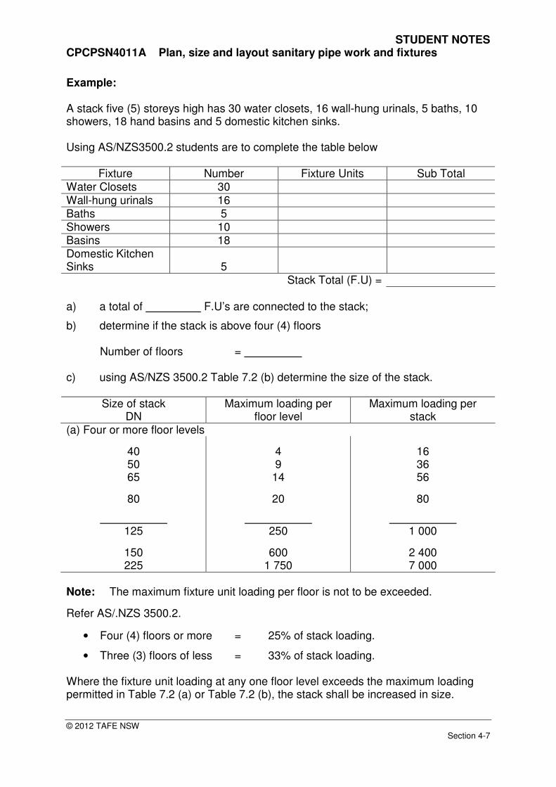
Example: A stack five (5) storeys high has 30 water closets, 16 wall-hung urinals, 5 baths, 10 showers, 18 hand basins and 5 domestic kitchen sinks. Using AS/NZS3500.2 students are to complete the table below
Fixture Number Fixture Units Sub Total Water Closets 30 Wall-hung urinals 16 Baths 5 Showers 10 Basins 18 Domestic Kitchen Sinks
5
Stack Total (F.U) = a) a total of F.U’s are connected to the stack;
b) determine if the stack is above four (4) floors Number of floors = c) using AS/NZS 3500.2 Table 7.2 (b) determine the size of the stack.
Size of stack DN
Maximum loading per floor level
Maximum loading per stack
(a) Four or more floor levels
40 50 65
80
125
150 225
4 9
14
20
250
600 1 750
16 36 56
80
1 000
2 400 7 000
Note: The maximum fixture unit loading per floor is not to be exceeded.
Refer AS/.NZS 3500.2.
• Four (4) floors or more = 25% of stack loading.
• Three (3) floors of less = 33% of stack loading. Where the fixture unit loading at any one floor level exceeds the maximum loading permitted in Table 7.2 (a) or Table 7.2 (b), the stack shall be increased in size.

STUDENT NOTES CPCPSN4011A Plan, size and layout sanitary pipe work and fixtures
© 2012 TAFE NSW Section 4-8
Where a DN 80 stack is installed as a fully vented modified system, the maximum number of water closet pans and slop hoppers connected to any graded pipe or branch shall not exceed two.
Student Exercise No 1
Students are required to size the stack shown in schematic view below; flush valves operate all water closet pans.
Fig. 4.3 Student Exercise
Second floor fixture unit loading
First floor fixture unit loading
Total
Stack Size = DN
NOT TO SCALE

STUDENT NOTES CPCPSN4011A Plan, size and layout sanitary pipe work and fixtures
© 2012 TAFE NSW Section 4-9
Student Exercise No 2 Students are required to size the stack shown in schematic view below, all water closet pans are cistern flush.
S
S
S
B B B
wc wc wc wc wc wcShr Shr
WC WCFW
BB
WC WC WC WC
WC WC WC WCFW
B B B B
WCWCWC
BBB
1st Floor
2nd Floor
3rd Floor
4th Floor
5th Floor
FW FW
B
CS Shr Shr Shr Shr
FW
Fig. 4.4 Student Exercise
Fixture unit loading
Stack Size = DN
NOT TO SCALE

STUDENT NOTES CPCPSN4011A Plan, size and layout sanitary pipe work and fixtures
© 2012 TAFE NSW Section 4-10
Student Exercise No 3 Students are required to size the stack shown in schematic view below, all water closet pans are cistern flush.
1st Floor
WCWCWC
BBB
FW
S
2nd Floor
Bth FW Shr
B
WC WC
3rd Floor
B B B B
FW
S
WC WC WC
Fig. 4.5 Student Exercise
Fixture unit loading
Stack Size = DN
NOT TO SCALE
STUDENT NOTES CPCPSN4011A Plan, size and layout sanitary pipe work and fixtures
© 2012 TAFE NSW Section 4-11
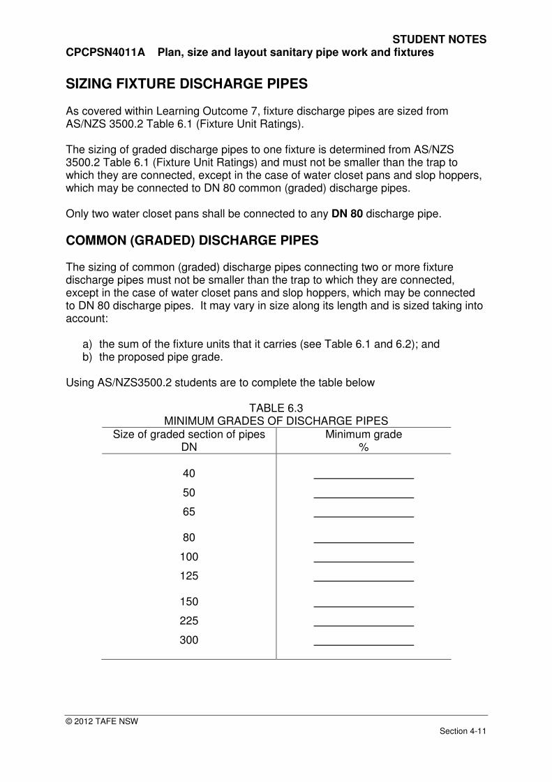
SIZING FIXTURE DISCHARGE PIPES As covered within Learning Outcome 7, fixture discharge pipes are sized from AS/NZS 3500.2 Table 6.1 (Fixture Unit Ratings). The sizing of graded discharge pipes to one fixture is determined from AS/NZS 3500.2 Table 6.1 (Fixture Unit Ratings) and must not be smaller than the trap to which they are connected, except in the case of water closet pans and slop hoppers, which may be connected to DN 80 common (graded) discharge pipes. Only two water closet pans shall be connected to any DN 80 discharge pipe.
COMMON (GRADED) DISCHARGE PIPES The sizing of common (graded) discharge pipes connecting two or more fixture discharge pipes must not be smaller than the trap to which they are connected, except in the case of water closet pans and slop hoppers, which may be connected to DN 80 discharge pipes. It may vary in size along its length and is sized taking into account:
a) the sum of the fixture units that it carries (see Table 6.1 and 6.2); and b) the proposed pipe grade.
Using AS/NZS3500.2 students are to complete the table below
TABLE 6.3 MINIMUM GRADES OF DISCHARGE PIPES
Size of graded section of pipes DN
Minimum grade %
40
50
65
80
100
125
150
225
300
STUDENT NOTES CPCPSN4011A Plan, size and layout sanitary pipe work and fixtures
© 2012 TAFE NSW Section 4-12
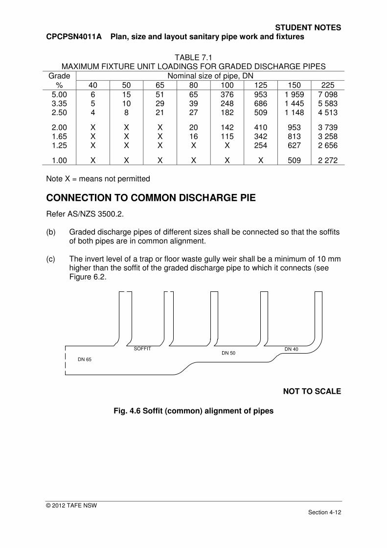
TABLE 7.1 MAXIMUM FIXTURE UNIT LOADINGS FOR GRADED DISCHARGE PIPES
Grade Nominal size of pipe, DN % 40 50 65 80 100 125 150 225
5.00 3.35 2.50
2.00 1.65 1.25
1.00
6 5 4
X X X
X
15 10 8
X X X
X
51 29 21
X X X
X
65 39 27
20 16 X
X
376 248 182
142 115 X
X
953 686 509
410 342 254
X
1 959 1 445 1 148
953 813 627
509
7 098 5 583 4 513
3 739 3 258 2 656
2 272 Note X = means not permitted
CONNECTION TO COMMON DISCHARGE PIE
Refer AS/NZS 3500.2. (b) Graded discharge pipes of different sizes shall be connected so that the soffits
of both pipes are in common alignment. (c) The invert level of a trap or floor waste gully weir shall be a minimum of 10 mm
higher than the soffit of the graded discharge pipe to which it connects (see Figure 6.2.
DN 65
DN 50DN 40SOFFIT
NOT TO SCALE
Fig. 4.6 Soffit (common) alignment of pipes
STUDENT NOTES CPCPSN4011A Plan, size and layout sanitary pipe work and fixtures
© 2012 TAFE NSW Section 4-13
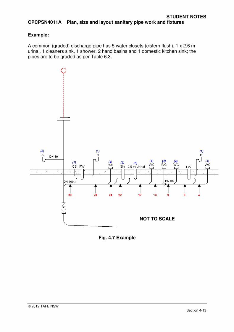
Example: A common (graded) discharge pipe has 5 water closets (cistern flush), 1 x 2.6 m urinal, 1 cleaners sink, 1 shower, 2 hand basins and 1 domestic kitchen sink; the pipes are to be graded as per Table 6.3.
Fig. 4.7 Example
NOT TO SCALE
STUDENT NOTES CPCPSN4011A Plan, size and layout sanitary pipe work and fixtures
© 2012 TAFE NSW Section 4-14
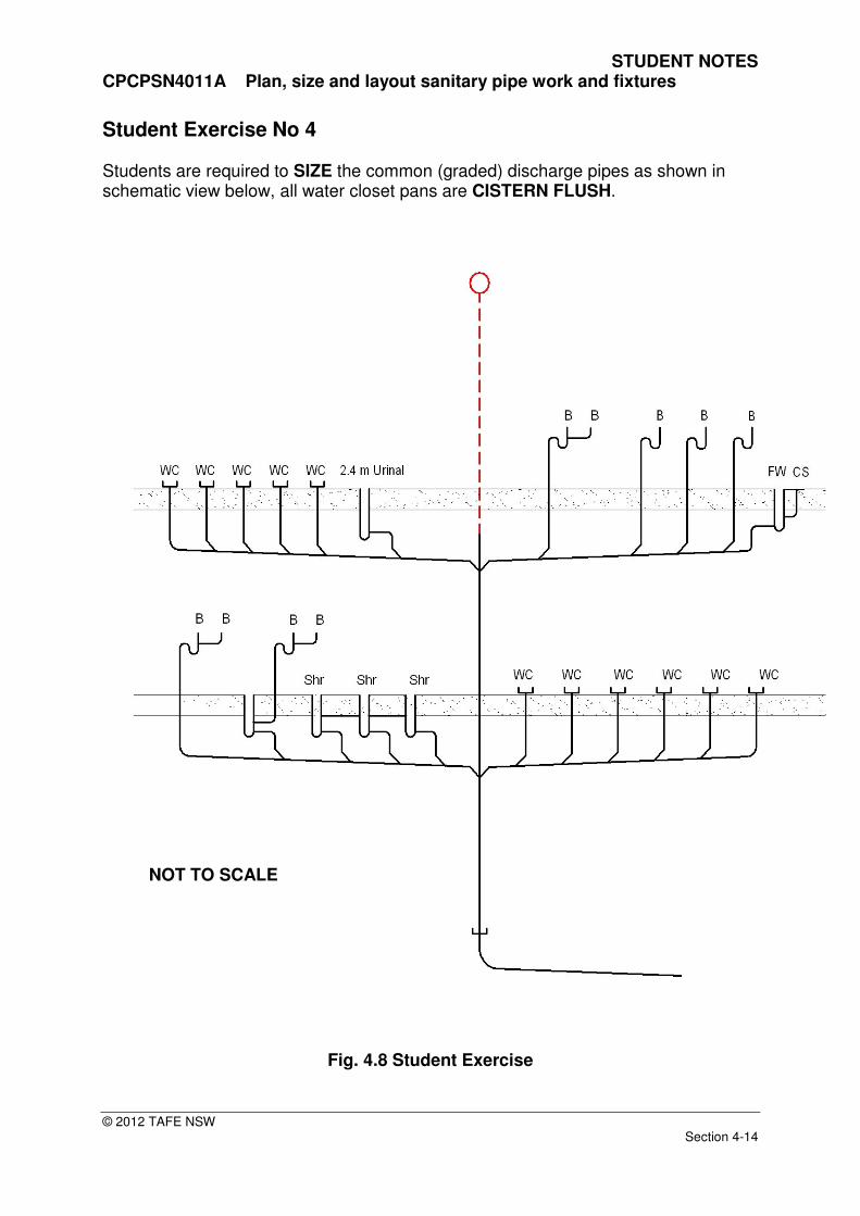
Student Exercise No 4 Students are required to SIZE the common (graded) discharge pipes as shown in schematic view below, all water closet pans are CISTERN FLUSH.
Fig. 4.8 Student Exercise
NOT TO SCALE

STUDENT NOTES CPCPSN4011A Plan, size and layout sanitary pipe work and fixtures
© 2012 TAFE NSW Section 4-15
Student Exercise No 5 Students are required to SIZE the common (graded) discharge pipes as shown in schematic view below, all water closet pans are CISTERN FLUSH.
Fig. 4.9 Student Exercise
NOT TO SCALE
STUDENT NOTES CPCPSN4011A Plan, size and layout sanitary pipe work and fixtures
© 2012 TAFE NSW Section 4-16
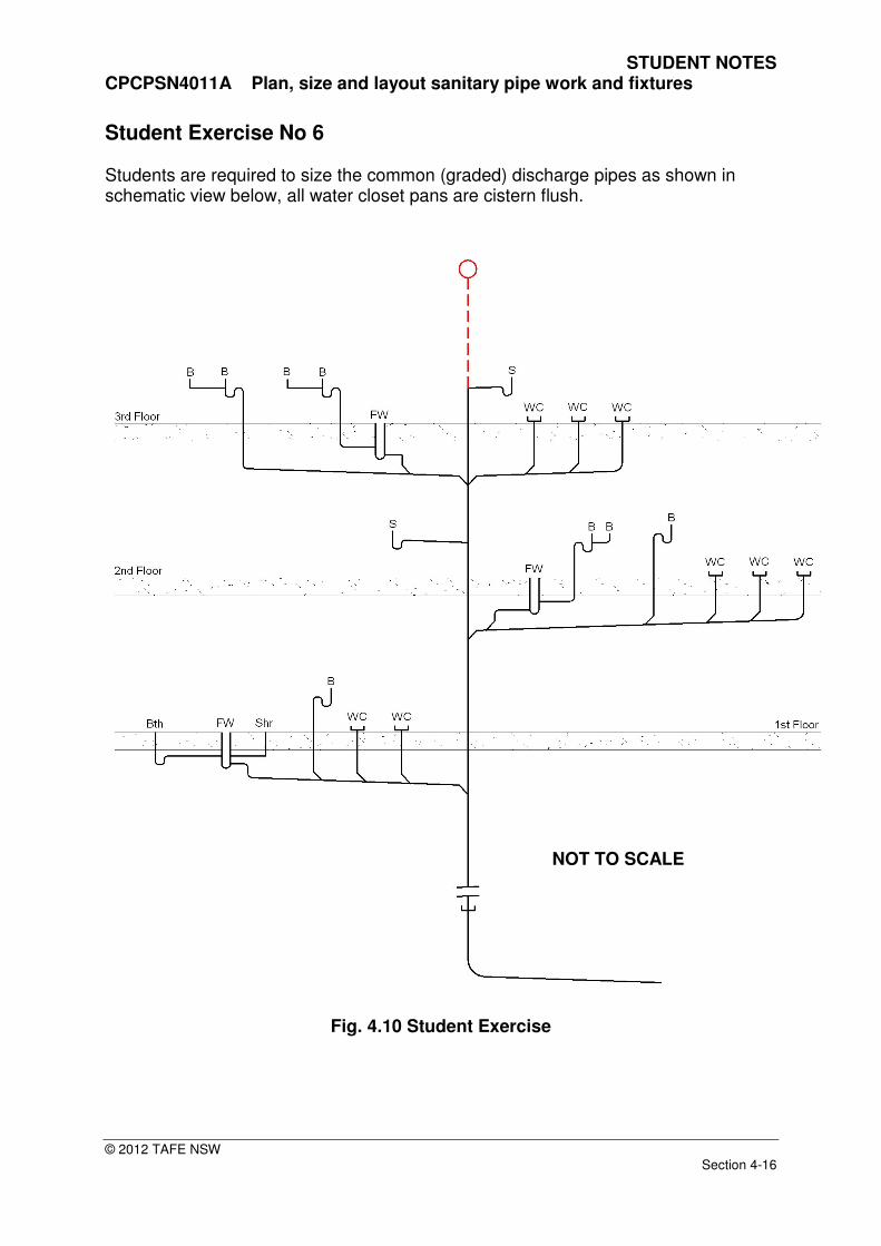
Student Exercise No 6 Students are required to size the common (graded) discharge pipes as shown in schematic view below, all water closet pans are cistern flush.
Fig. 4.10 Student Exercise
NOT TO SCALE

STUDENT NOTES CPCPSN4011A Plan, size and layout sanitary pipe work and fixtures
© 2012 TAFE NSW Section 4-17
STACK VENT
Refer AS/NZS 3500.2. A stack vent is the continuation of the stack above the highest branch; it may extend separately to atmosphere or interconnect with the relief vent above the overflow level of the highest fixture connected. Stack and Relief vents are sized using AS/NZS 3500.2 Table 7.5 and the following:
a) the sum of the fixture units that discharge into the stack (see Table 6.1 and 6.2); and
b) the size of the stack. c) the developed length of the vent The developed length of a stack vent is:
• for stacks with relief vents, the length of the relief vent; or
• for stacks without relief vents, the length of the stack vent and the stack to the point of connection of the lowest branch.
STUDENT NOTES CPCPSN4011A Plan, size and layout sanitary pipe work and fixtures
© 2012 TAFE NSW Section 4-18
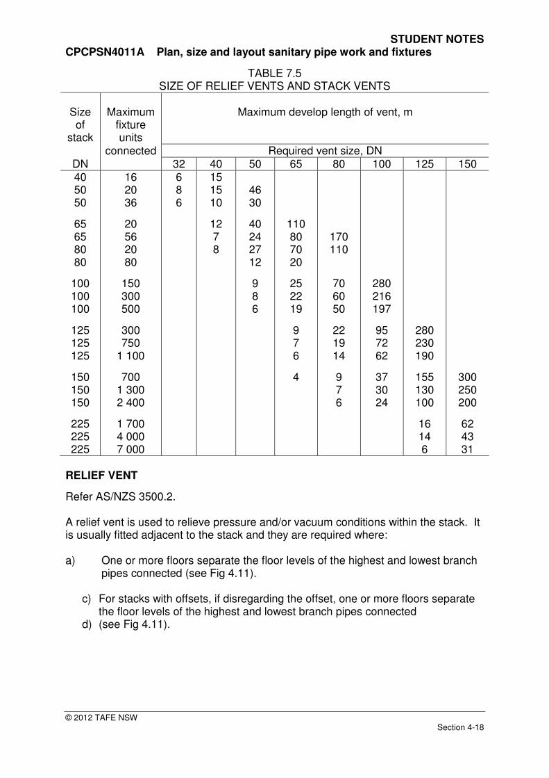
TABLE 7.5 SIZE OF RELIEF VENTS AND STACK VENTS
Size of
stack
Maximum
fixture units
Maximum develop length of vent, m
connected Required vent size, DN DN 32 40 50 65 80 100 125 150 40 50 50
65 65 80 80
100 100 100
125 125 125
150 150 150
225 225 225
16 20 36
20 56 20 80
150 300 500
300 750
1 100
700 1 300 2 400
1 700 4 000 7 000
6 8 6
15 15 10
12 7 8
46 30
40 24 27 12
9 8 6
110 80 70 20
25 22 19
9 7 6
4
170 110
70 60 50
22 19 14
9 7 6
280 216 197
95 72 62
37 30 24
280 230 190
155 130 100
16 14 6
300 250 200
62 43 31
RELIEF VENT
Refer AS/NZS 3500.2. A relief vent is used to relieve pressure and/or vacuum conditions within the stack. It is usually fitted adjacent to the stack and they are required where: a) One or more floors separate the floor levels of the highest and lowest branch
pipes connected (see Fig 4.11).
c) For stacks with offsets, if disregarding the offset, one or more floors separate the floor levels of the highest and lowest branch pipes connected
d) (see Fig 4.11).
STUDENT NOTES CPCPSN4011A Plan, size and layout sanitary pipe work and fixtures
© 2012 TAFE NSW Section 4-19
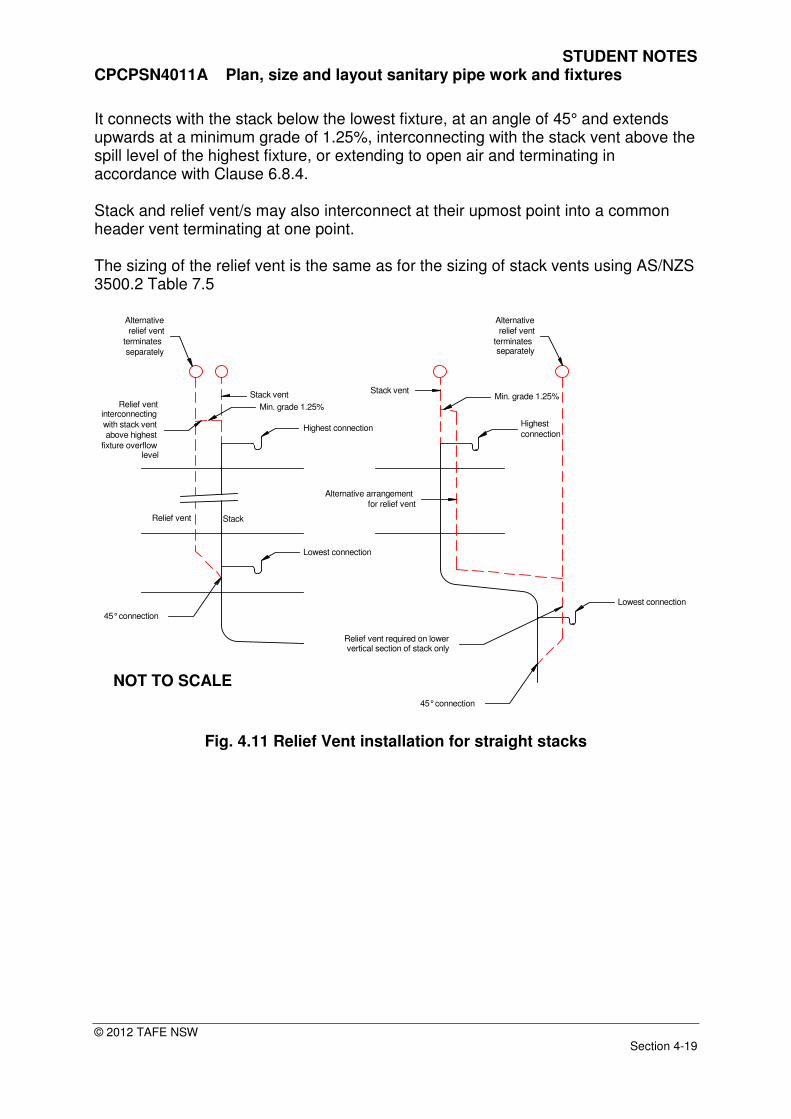
It connects with the stack below the lowest fixture, at an angle of 45° and extends upwards at a minimum grade of 1.25%, interconnecting with the stack vent above the spill level of the highest fixture, or extending to open air and terminating in accordance with Clause 6.8.4. Stack and relief vent/s may also interconnect at their upmost point into a common header vent terminating at one point. The sizing of the relief vent is the same as for the sizing of stack vents using AS/NZS 3500.2 Table 7.5
Highest connection
Lowest connection
Stack vent
Relief vent Stack
Min. grade 1.25%Relief ventinterconnecting
with stack vent
above highest
fixture overflowlevel
Alternative
relief vent
terminates
separately
Highest
connection
Lowest connection
45° connection
Alternative
relief vent
terminates separately
45° connection
Relief vent required on lowervertical section of stack only
Alternative arrangement
for relief vent
Min. grade 1.25%Stack vent
Fig. 4.11 Relief Vent installation for straight stacks
NOT TO SCALE

STUDENT NOTES CPCPSN4011A Plan, size and layout sanitary pipe work and fixtures
© 2012 TAFE NSW Section 4-20
45° connection
Stack vent
Min. grade 1.25%
45° connection
Alternative
relief vent
terminates
separately
Aternative arrangement
for relief ventRelief vent required
on both vertical
of stack
Relief vent required
on both vertical
of stack
Fig. 4.12 Relief Vent installation for graded offsets
PRESSURE ATTENUATORS Pressure attenuators may be used in sanitary plumbing systems as an alternative to relief venting. Attenuators are used to counter the tendency for the loss of trap water seals resulting from positive pressure pulses in discharge stacks. Positive pressure pulses or transients arise from disruptions to airflow produced at changes in direction or restriction to the airflow path. The size of the pressure attenuator is independent of stack size and fixture unit loading the manufactures advice may need to be obtained.
Installation requirements Pressure attenuators shall be— (a) connected to stacks by means of 45° or sweep junctions; (b) positioned above the point of connection in either a vertical or horizontal
orientation and
NOT TO SCALE
STUDENT NOTES CPCPSN4011A Plan, size and layout sanitary pipe work and fixtures
© 2012 TAFE NSW Section 4-21
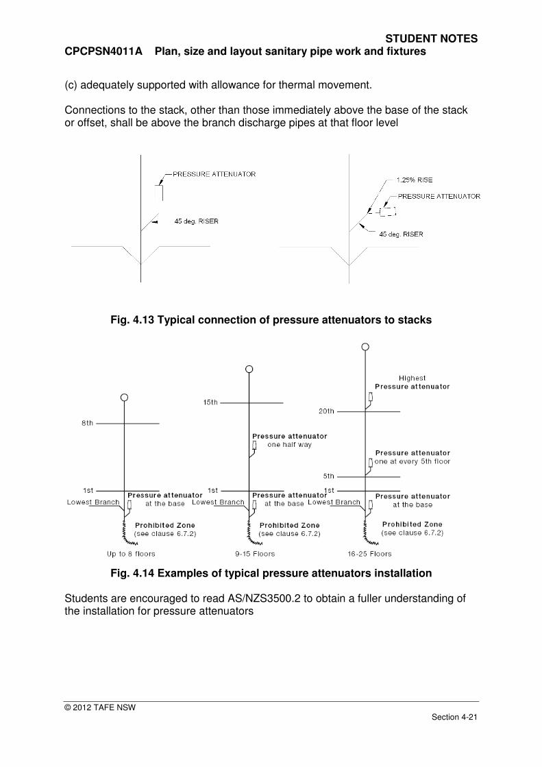
(c) adequately supported with allowance for thermal movement. Connections to the stack, other than those immediately above the base of the stack or offset, shall be above the branch discharge pipes at that floor level
Fig. 4.13 Typical connection of pressure attenuators to stacks
Fig. 4.14 Examples of typical pressure attenuators installation
Students are encouraged to read AS/NZS3500.2 to obtain a fuller understanding of the installation for pressure attenuators
STUDENT NOTES CPCPSN4011A Plan, size and layout sanitary pipe work and fixtures
© 2012 TAFE NSW Section 4-22
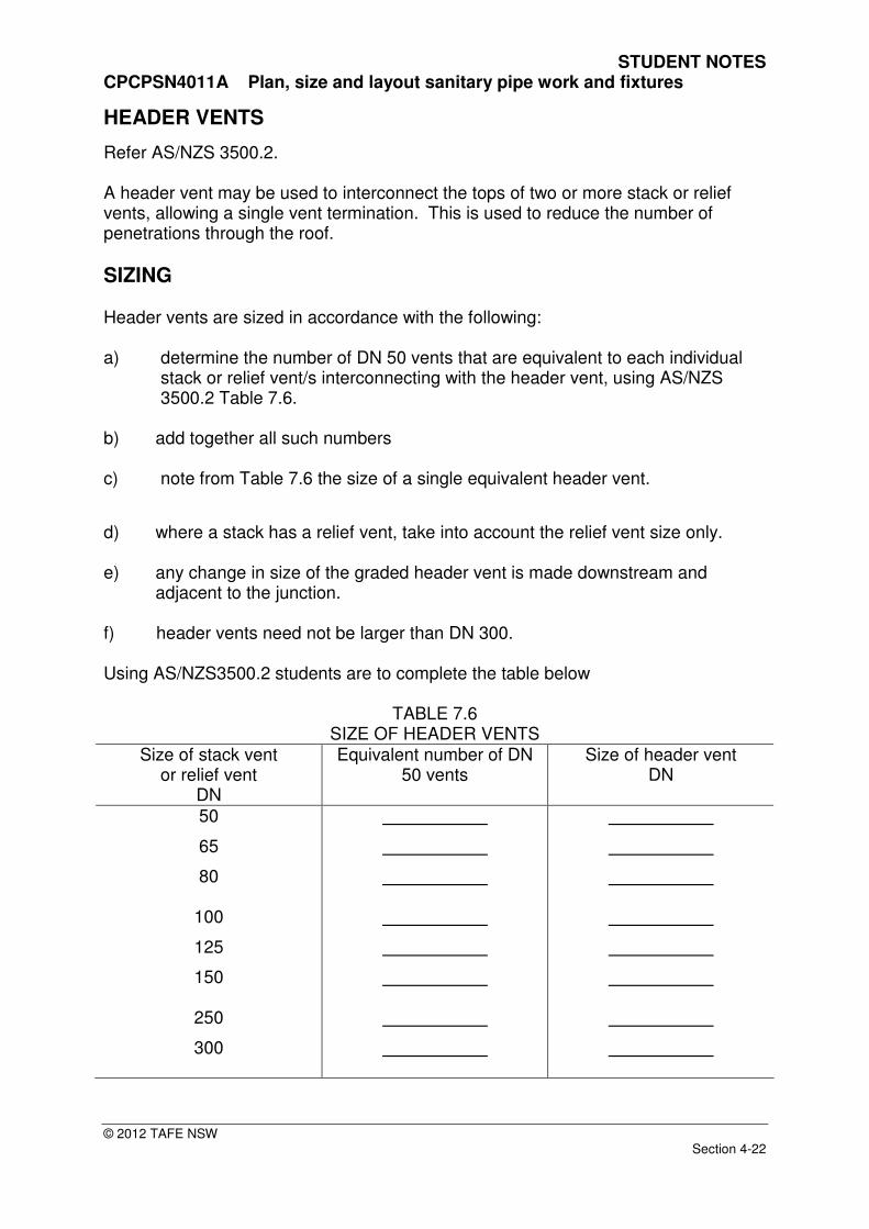
HEADER VENTS
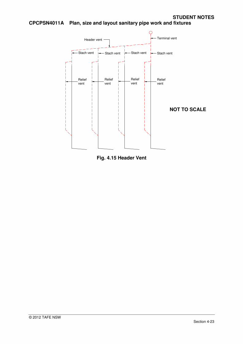
Refer AS/NZS 3500.2. A header vent may be used to interconnect the tops of two or more stack or relief vents, allowing a single vent termination. This is used to reduce the number of penetrations through the roof.
SIZING Header vents are sized in accordance with the following: a) determine the number of DN 50 vents that are equivalent to each individual
stack or relief vent/s interconnecting with the header vent, using AS/NZS 3500.2 Table 7.6.
b) add together all such numbers c) note from Table 7.6 the size of a single equivalent header vent.
d) where a stack has a relief vent, take into account the relief vent size only. e) any change in size of the graded header vent is made downstream and
adjacent to the junction. f) header vents need not be larger than DN 300. Using AS/NZS3500.2 students are to complete the table below
TABLE 7.6 SIZE OF HEADER VENTS
Size of stack vent or relief vent
DN
Equivalent number of DN 50 vents
Size of header vent DN
50
65
80
100
125
150
250
300
STUDENT NOTES CPCPSN4011A Plan, size and layout sanitary pipe work and fixtures
© 2012 TAFE NSW Section 4-23
Terminal vent
Stach vent
Relief vent
Header vent
Stach ventStach ventStach vent
Relief
ventRelief
ventRelief vent
Fig. 4.15 Header Vent
NOT TO SCALE

STUDENT NOTES CPCPSN4011A Plan, size and layout sanitary pipe work and fixtures
© 2012 TAFE NSW Section 4-24
Student Exercise No 7
Students are required to size the header vent as shown in schematic view below, the
stack is a fully vented modified system with a develop length of 20 m.
Fig. 4.16 Student Exercise NOT TO SCALE
Section Number of DN 50 equivalents
Header vent size DN
A – B B – C C – D D - E
STUDENT NOTES CPCPSN4011A Plan, size and layout sanitary pipe work and fixtures
© 2012 TAFE NSW Section 4-25
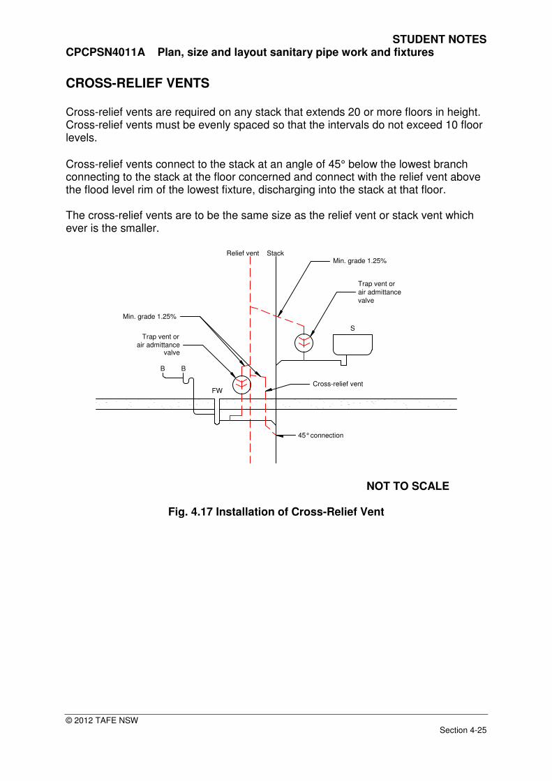
CROSS-RELIEF VENTS Cross-relief vents are required on any stack that extends 20 or more floors in height. Cross-relief vents must be evenly spaced so that the intervals do not exceed 10 floor levels.
Cross-relief vents connect to the stack at an angle of 45° below the lowest branch connecting to the stack at the floor concerned and connect with the relief vent above the flood level rim of the lowest fixture, discharging into the stack at that floor. The cross-relief vents are to be the same size as the relief vent or stack vent which ever is the smaller.
B B
S
FW
Trap vent or
air admittancevalve
Trap vent or
air admittance
valve
Min. grade 1.25%StackRelief vent
45° connection
Cross-relief vent
Min. grade 1.25%
NOT TO SCALE
Fig. 4.17 Installation of Cross-Relief Vent

STUDENT NOTES CPCPSN4011A Plan, size and layout sanitary pipe work and fixtures
© 2012 TAFE NSW Section 4-26
Sanitary Drain45° connection
1 st Floor
4th Floor
3rd Floor
2nd Floor Group vent or
air admittance
valve
5th Floor
6th Floor
7th Floor
8th Floor
9th Floor
10th Floor
11th Floor
12th Floor
13th Floor
14th Floor
15th Floor
19th Floor
18th Floor
17th Floor
16th Floor
20th Floor
45° connection
Highest graded pipe
or branch connection
to stack
Max.10th floor
level between
Cross-relief vents
Cross-relief vent not
required untill stack
exceeds 20 floor levels
Trap vent or
air admittancevalve
Cross-relief vent
Fig. 4.18 Installation of Cross-Relief Vent
NOT TO SCALE
STUDENT NOTES CPCPSN4011A Plan, size and layout sanitary pipe work and fixtures
© 2012 TAFE NSW Section 4-27
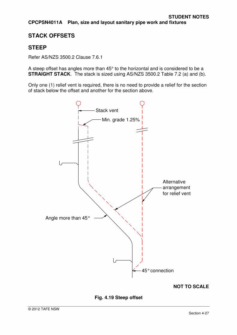
STACK OFFSETS
STEEP
Refer AS/NZS 3500.2 Clause 7.6.1
A steep offset has angles more than 45° to the horizontal and is considered to be a STRAIGHT STACK. The stack is sized using AS/NZS 3500.2 Table 7.2 (a) and (b). Only one (1) relief vent is required, there is no need to provide a relief for the section of stack below the offset and another for the section above.
Alternativearrangement
for relief vent
Min. grade 1.25%
Stack vent
45° connection
Angle more than 45°
NOT TO SCALE
Fig. 4.19 Steep offset

STUDENT NOTES CPCPSN4011A Plan, size and layout sanitary pipe work and fixtures
© 2012 TAFE NSW Section 4-28
GRADED
Refer AS/NZS 3500.2.
A stack offset is considered to be graded if its angle is less than 45° to the horizontal.
45° connection
Stack vent
Min. grade 1.25%
45° connection
Alternative
relief vent
terminates
separately
Aternative arrangement
for relief ventRelief vent required
on both vertical
of stack
Relief vent required
on both vertical
of stack
Fig. 4.20 Graded offset
NOT TO SCALE
STUDENT NOTES CPCPSN4011A Plan, size and layout sanitary pipe work and fixtures
© 2012 TAFE NSW Section 4-29
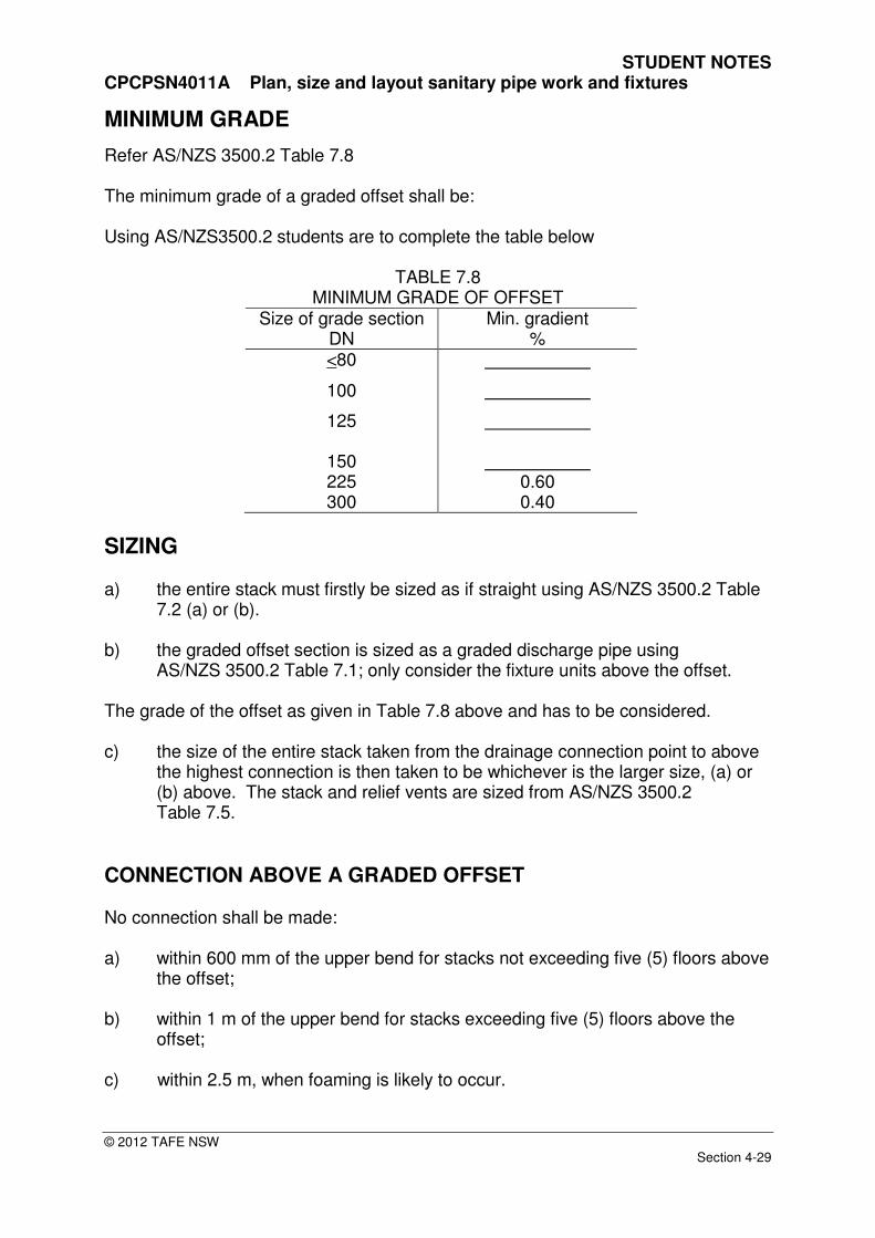
MINIMUM GRADE
Refer AS/NZS 3500.2 Table 7.8 The minimum grade of a graded offset shall be:
Using AS/NZS3500.2 students are to complete the table below
TABLE 7.8
MINIMUM GRADE OF OFFSET Size of grade section
DN Min. gradient
% <80
100
125
150 225 300
0.60 0.40
SIZING a) the entire stack must firstly be sized as if straight using AS/NZS 3500.2 Table
7.2 (a) or (b). b) the graded offset section is sized as a graded discharge pipe using
AS/NZS 3500.2 Table 7.1; only consider the fixture units above the offset. The grade of the offset as given in Table 7.8 above and has to be considered. c) the size of the entire stack taken from the drainage connection point to above
the highest connection is then taken to be whichever is the larger size, (a) or (b) above. The stack and relief vents are sized from AS/NZS 3500.2 Table 7.5.
CONNECTION ABOVE A GRADED OFFSET No connection shall be made: a) within 600 mm of the upper bend for stacks not exceeding five (5) floors above
the offset; b) within 1 m of the upper bend for stacks exceeding five (5) floors above the
offset; c) within 2.5 m, when foaming is likely to occur.

STUDENT NOTES CPCPSN4011A Plan, size and layout sanitary pipe work and fixtures
© 2012 TAFE NSW Section 4-30
CONNECTION WITHIN A GRADED OFFSETS No connection shall be made: a) within 2.5 m of the upper bend; and
b) within 450 mm of the lower bend.
CONNECTION BELOW A GRADED OFFSETS No connection shall be made: a) within 600 mm of the lower bend.
450 mm min.
600 mm min.
Alternative connection
for lowest branch
2500 mm min.
2nd Floor
3rd Floor
No connection within
this zone
No connection within
this zone
600 mm (5 or less floors)
1 m (6 or more floors)
Alternative connection
for above graded offset
1st Floor
Fig. 4.21 Connection within offset area
NOT TO SCALE
STUDENT NOTES CPCPSN4011A Plan, size and layout sanitary pipe work and fixtures
© 2012 TAFE NSW Section 4-31
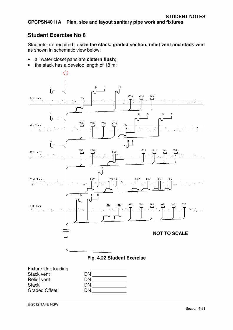
Student Exercise No 8
Students are required to size the stack, graded section, relief vent and stack vent as shown in schematic view below:
• all water closet pans are cistern flush;
• the stack has a develop length of 18 m;
Fig. 4.22 Student Exercise
Fixture Unit loading Stack vent DN Relief vent DN Stack DN Graded Offset DN
NOT TO SCALE

STUDENT NOTES CPCPSN4011A Plan, size and layout sanitary pipe work and fixtures
© 2012 TAFE NSW Section 4-32
VENTING OF COMMON (GRADED) DISCHARGE PIPES The following vents are used to eliminate pressure build up and vacuum conditions within graded discharge pipes for the prevention of loss of water seal/s.
TRAP VENT Trap vents are used to vent an individual trap to open air or interconnect with a branch vent, relief vent or stack vent. Air admittance may be used instead of a trap vent as outlined within AS/NZS 3500.2. Every trap vent shall be extended upwards to a point above the flood level rim of the fixture before interconnecting with another vent.
StackRelief vent
100 mm min rise
INSERT N.T.S
Min. 100 mm rise
Trap vent orair admittance
valve
Trap vent or
air admittance
valve
Fig. 4.23 Trap Vent
Trap vents are sized off the fixture discharge trap and pipe to which they are connected:
TABLE 7.3 MINIMUM SIZE OF TRAP VENTS
Size of fixture trap DN
Size of trap vent DN
40
<50 to <100
32
40
NOT TO SCALE
STUDENT NOTES CPCPSN4011A Plan, size and layout sanitary pipe work and fixtures
© 2012 TAFE NSW Section 4-33
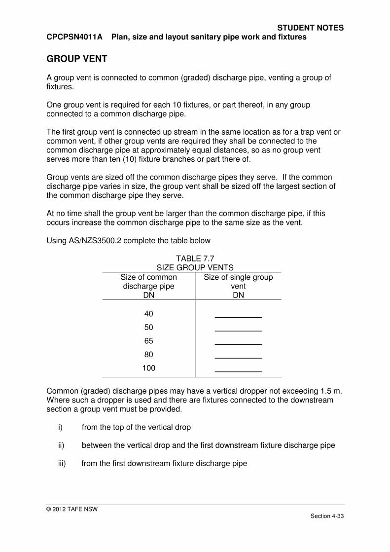
GROUP VENT A group vent is connected to common (graded) discharge pipe, venting a group of fixtures. One group vent is required for each 10 fixtures, or part thereof, in any group connected to a common discharge pipe. The first group vent is connected up stream in the same location as for a trap vent or common vent, if other group vents are required they shall be connected to the common discharge pipe at approximately equal distances, so as no group vent serves more than ten (10) fixture branches or part there of. Group vents are sized off the common discharge pipes they serve. If the common discharge pipe varies in size, the group vent shall be sized off the largest section of the common discharge pipe they serve. At no time shall the group vent be larger than the common discharge pipe, if this occurs increase the common discharge pipe to the same size as the vent. Using AS/NZS3500.2 complete the table below
TABLE 7.7 SIZE GROUP VENTS
Size of common discharge pipe
DN
Size of single group vent DN
40
50
65
80
100
Common (graded) discharge pipes may have a vertical dropper not exceeding 1.5 m. Where such a dropper is used and there are fixtures connected to the downstream section a group vent must be provided.
i) from the top of the vertical drop
ii) between the vertical drop and the first downstream fixture discharge pipe
iii) from the first downstream fixture discharge pipe

STUDENT NOTES CPCPSN4011A Plan, size and layout sanitary pipe work and fixtures
© 2012 TAFE NSW Section 4-34
Group ventalternative
positions
Drop 1500 mm max.
Group vent
Branch Vent Group venting of
vertical dropper
alternative positions
Venting of discharge pipe
due to over distance or
more than one fixture
discharge pipe connected Vent connection
within 1.5 m from
weir of trap
S
S
WC
Vent interconnection above
flood level rim of highestfixture connected to commongraded discharge pipe
Air admittance valves maybe used to replace trap orgroup vents. Refer AS/NZS 3500.2 Clause 6.9
Discharge pipe
increased from DN 40 - 50 to
service the vent
B
B
Min. grade 1.25%
Vent connection
within 600 mm for
a basin/bidet and1.5 m for other
fixtures from
weir of trap
Fig. 4.24 Venting of Common Discharge Pipe
Connecting vents to a graded or common discharge pipe
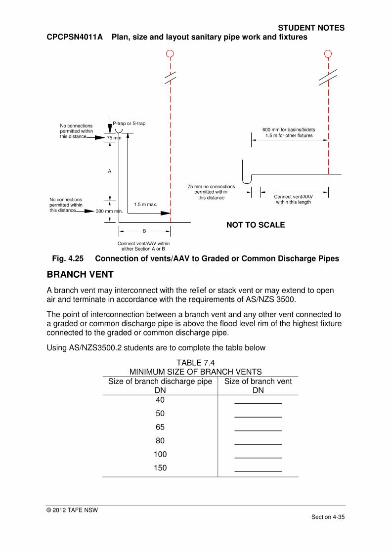
When connecting a vent or Air Admittance Valve (AAV) to a graded or common discharge pipe, it must meet the requirements of AS/NZS 3500.2. a) In the case of basins and bidets, the vent/AAV shall be connected no closer
than 75 mm and no further than 600 mm from the crown of the fixture trap, provided no change of direction occurs between the trap and the vent/AAV.
b) In the case of fixtures other than basins and bidets, the vent/AAV shall be
connected between 75 mm and 1.5 m, provided that where an S-trap or a bend is fitted downstream of a P-trap, the vent/AAV connected on the vertical discharge pipe shall be at least 300 mm from any bend at the base of the vertical section.
NOT TO SCALE
STUDENT NOTES CPCPSN4011A Plan, size and layout sanitary pipe work and fixtures
© 2012 TAFE NSW Section 4-35
300 mm min.
1.5 m max.
75 mm
A
B
Connect vent/AAV within either Section A or B
P-trap or S-trapNo connectionspermitted withinthis distance
Connect vent/AAVwithin this length
75 mm no connectionspermitted within
this distance
600 mm for basins/bidets
1.5 m for other fixtures
No connectionspermitted withinthis distance
Fig. 4.25 Connection of vents/AAV to Graded or Common Discharge Pipes
BRANCH VENT
A branch vent may interconnect with the relief or stack vent or may extend to open air and terminate in accordance with the requirements of AS/NZS 3500.
The point of interconnection between a branch vent and any other vent connected to a graded or common discharge pipe is above the flood level rim of the highest fixture connected to the graded or common discharge pipe.
Using AS/NZS3500.2 students are to complete the table below
TABLE 7.4 MINIMUM SIZE OF BRANCH VENTS
Size of branch discharge pipe DN
Size of branch vent DN
40
50
65
80
100
150
NOT TO SCALE

STUDENT NOTES CPCPSN4011A Plan, size and layout sanitary pipe work and fixtures
© 2012 TAFE NSW Section 4-36
Student Exercise No 10 Students are required to complete the design showing the position, type and size of vents required for the system shown in schematic view below, all water closet pans are cistern flush.
Fig. 4.26 Student Exercise
NOT TO SCALE
STUDENT NOTES CPCPSN4011A Plan, size and layout sanitary pipe work and fixtures
© 2012 TAFE NSW Section 4-37
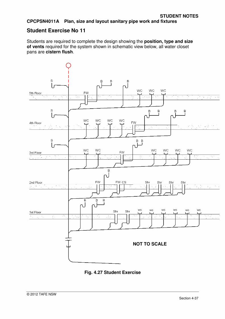
Student Exercise No 11 Students are required to complete the design showing the position, type and size of vents required for the system shown in schematic view below, all water closet pans are cistern flush.
Fig. 4.27 Student Exercise
NOT TO SCALE

STUDENT NOTES CPCPSN4011A Plan, size and layout sanitary pipe work and fixtures
© 2012 TAFE NSW Section 4-38
Student Exercise No 12 Students are required to complete the design showing the position and capacity of air admittance valves (trap and group vents only) for the system shown in schematic view below, all water closet pans are cistern flush.
Fig. 4.28 Student Exercise
NOT TO SCALE

STUDENT NOTES CPCPSN4011A Plan, size and layout sanitary pipe work and fixtures
© 2012 TAFE NSW Section 4-39
Student Exercise No 13 Students are required to complete the design showing the position and capacity of air admittance valves (trap and group vents only) for the system shown in schematic view below, all water closet pans are cistern flush.
Fig. 4.29 Student Exercise
NOT TO SCALE