Level 3 Diploma in Electrical Power Engineering - Overhead ...

ElEctrical SErvicE rEquirEmEntSPage 3 - 1
Section 3. Overhead Service
Revised 10/03/2019New: 10/90
tablE of contEntS
Section 3Overhead Service
A. GENERAL .......................................................................................................................... 3-3
B. TEMPORARY CONSTRUCTION SERVICE .................................................................. 3-3
C. SECONDARY SERVICE (600 VOLTS AND UNDER) .................................................. 3-5
D. PRIMARY SERVICE - INDIVIDUAL RESIDENCE ..................................................... 3-18
E. RESIDENTIAL PLAT & SUBDIVISION - LINE EXTENSION ................................... 3-20
F. CONVENIENCE POLES ................................................................................................. 3-20
G. SERVICE POLES ............................................................................................................. 3-20
H. METER POLES ................................................................................................................ 3-20
I. AREA LIGHT - OVERHEAD FEED - RESIDENTIAL ................................................. 3-25
J. MISCELLANEOUS POLE ATTACHMENTS ............................................................... 3-26
Table of ConTenTs

Section 3. Overhead Service
ElEctrical SErvicE rEquirEmEntSPage 3 - 2Revised 10/03/2019New: 10/90
Section 3Illustrations And Tables
FIGURE 3-1 TEMPORARY OH CONSTRUCTION SERVICE.......................................... 3-4
FIGURE 3-2 SERVICE CLEARANCE ................................................................................. 3-6
FIGURE 3-3 MINIMUM SERVICE CLEARANCES........................................................... 3-7
FIGURE 3-4 SERVICE MAST BRACKET .......................................................................... 3-8
FIGURE 3-5 DEADEND HOUSE BRACKET ..................................................................... 3-8
FIGURE 3-6 KINDORF / UNISTRUT BRACKET .............................................................. 3-8
FIGURE 3-7 HEAVY DUTY SERVICE BRACKET ........................................................... 3-8
FIGURE 3-8 OH MAST SURFACE MOUNTING SPECIFICATIONS .............................. 3-9
FIGURE 3-9 OH MAST FLUSH MOUNTING SPECIFICATIONS ................................ 3-10
FIGURE 3-10 GUYING / BRACING OH SERVICE MASTS ............................................. 3-11
FIGURE 3-11 MASTHEAD WALL MOUNTING SPECIFICATIONS .............................. 3-12
FIGURE 3-12 MAST LOCATION ACCESSIBILITY ......................................................... 3-14
FIGURE 3-13 ALTERNATE MAST STRIKE LOCATION ................................................ 3-15
FIGURE 3-14 OH CT ENCLOSURE / 201 - 400 AMP ........................................................ 3-16
FIGURE 3-15 OH MAST SURFACE MOUNTING / 201 - 400 AMP ................................. 3-17
FIGURE 3-16 CLEARING FOR OH LINE EXTENSION ................................................... 3-19
FIGURE 3-17 METER POLE CLEARANCES (LOCATION OF METER POLE) ............. 3-21
FIGURE 3-18 METER POLE CLEARANCES (JOINT OCCUPANCY) ............................ 3-22
FIGURE 3-19 TYPICAL METER POLE INSTALLATIONS .............................................. 3-24
FIGURE 3-20 METER POLES – OVER 200 AMP .............................................................. 3-25
FIGURE 3-21 AREA LIGHT - OVERHEAD FEED - RESIDENTIAL ............................... 3-26
FIGURE 3-22 CATV POWER SUPPLIES ............................................................................ 3-28
FIGURE 3-23 TEMPORARY POLE ATTACHMENT ........................................................ 3-29
TABLE 1 METER POLE SPECIFICATIONS AND SETTING DEPTH ...................... 3-23
Table of IllusTraTIons and Tables

ElEctrical SErvicE rEquirEmEntSPage 3 - 3
Section 3. Overhead Service
Revised 10/03/2019New: 10/90
OVERHEAD SERVICEA. GENERAL
1. All conditions for service application, availability of service, type of service, inspection, right-of-way, easements, etc., are covered in Section 2, General Requirements.
2. The District will determine when it will extend its overhead distribution facilities to serve permanent residential or commercial customers.
3. The customer shall do all tree trimming on private property necessary for safe construction and operation of the District’s electrical facilities, prior to construction.
B. TEMPORARY CONSTRUCTION SERVICE
1. When a service is determined by the District to be temporary, the customer is required to pay charges in accordance with the District's CusTomer servICe regulaTIons.
2. Temporarary service installations shall be on private property.
3. Temporary services are limited to 18 months.
4. Temporary service conductors include a maximum of 150' of District supplied #6 aluminum secondary service conductor.
5. Access must be provided by the customer between the service attachment and the District’s facilities.
6. The preferred location of a temporary service shall be accessible by a District service truck within 15 feet of a drivable surface.
7. The service equipment shall include a suitable support post and bracing with an approved attachment insulator spool, UL listed or approved conduit and weatherhead, meter socket, weatherproof disconnect switch and receptacle box with #4 copper ground wire, clamp and ground rod.
8. A minimum of a 4" x 4" timber 14' in length will be accepted if braced a minimum of two ways. Refer to Figure 3-1. Temporary service equipment on trees or the District's distribution, transmission or street light poles is not acceptable.
9. The meter socket shall be an approved type, meeting the requirements of the National Electrical Code and the District’s requirements. Water pipe or water pipe fittings are not acceptable. Service entrance cable may be used where permitted by state or city regulations.
10. The neutral wire between the weatherhead and switchbox shall be bonded to the meter socket using the grounding screw or bonding terminal.

Section 3. Overhead Service
ElEctrical SErvicE rEquirEmEntSPage 3 - 4Revised 10/03/2019New: 10/90
11. If temporary is accessible by a District service truck (within 15 feet of a driveable surface) a minimum of 18 inches of line side wire shall be left for connection at the weatherhead. If temporary is not accessible by a District service truck the customer shall attach the line side wire to the attachment insulator spool and leave enough line size wire to reach the ground for attachment to the District provided service wire.
12. The service conductors shall be coded and the neutral conductor shall be identified by the color white or light gray. The ground wire shall be a minimum of #8 AWG copper.
13. The point of attachment shall be high enough above the ground to provide the proper clearances. Refer to Figure 3-3.
14. Service entrance equipment shall include proper provisions for grounding portable tools and equipment in accordance with the National Electrical Code and such equipment shall be of factory built, rain-tight construction when exposed to the weather.
15. The District will provide the service drop, make appropriate connections and install the meter(s).
16. The District will not energize service until the installation is approved by the appropriate electrical inspector.
Figure 3-1
TeMPOrArY

ElEctrical SErvicE rEquirEmEntSPage 3 - 5
Section 3. Overhead Service
Revised 10/03/2019New: 10/90
C. SECONDARY SERVICE (600 VOLTS AND UNDER)
1. Service drop conductors will not be installed until all electrical inspections have been completed and approved by the District and the governmental agency having jurisdiction.
2. The service entrance shall be located so that only one set of service wire attachments (of like voltage) will be required.
3. The District will designate the point of attachment for all service drop conductors and the location of the service entrance equipment. When a pole is required for the customer’s convenience, the cost and condition shall be in accordance with the District’s CusTomer servICe regulaTIons.
4. Service Clearing
a. Remove trees and limbs a minimum of 5 feet on all sides of proposed service drop route. This is to be maintained by the customer, contact Customer Engineering for possible assistance. The District will trim the first 10' nearest it's Primary High Voltage Line(s). Refer to Figure 3-2.
b. Remove leaning trees beyond the 5 feet minimum on each side which constitute a potential hazard to the proposed line.
c. It is recommended that any trees that may present a future hazard to the service wire (i.e., rotting, dead, or leaning trees that may fall or be blown down) should be removed.
d. Should it be necessary to run a service drop through a more congested area than described above, it is the customer's responsibility to top or remove all trees or obstacles taller than 12-1/2 feet within the service drop area.
Exception: Very large Evergreen (i.e., Fir and Cedar) may be left if mutually agreed upon by the customer and the District representative. No variance form required. Side trimming is required.
TeMPOrArY

Section 3. Overhead Service
ElEctrical SErvicE rEquirEmEntSPage 3 - 6Revised 10/03/2019New: 10/90
SerViCe CLeArANCe
Figure 3-2

ElEctrical SErvicE rEquirEmEntSPage 3 - 7
Section 3. Overhead Service
Revised 10/03/2019New: 10/90
5. Minimum Service Clearances
a. Where the roof is readily accessible and the service voltage is 120/240V the service drop conductors shall have a clearance of not less than 10 feet from the highest point of the roof over which it passes. Where the roof is or is not readily accessible and the service voltage is 277/480V the service drop conductors shall have a clearance of not less than 10 feet from the highest point of the roof over which it passes. NESC 234.C.3.d.(1). However, the clearance may not be less than 3 feet where the voltage between conductors does not exceed 300 volts and the roof is not readily accessible or cannot be readily walked upon. These clearances shall be maintained except within 4 feet of the point of attachment. Reference NESC 234 .C.3.d.(1).
b. The service attachment bracket shall be a minimum of 10 feet above the ground at the point of attachment and high enough to maintain a service conductor clearance of 10 feet over a finished grade or working platform, 15-1/2 feet over residential driveways*, 18 feet over city, county or private roads, streets, alleys and all driveways other than residential, and 24 feet over State highways. The point of attachment shall not be more than 17 feet above the grade unless specifically approved by the District. Refer to Figure 3-3 and Figure 3-12.
* EXCEPTION: Where the height of attachment to a building or other installation does not permit 15-1/2 feet of clearance, clearances over residential driveways may be reduced to 12 feet for supply service drops limited to 150 volts to ground (NESC 232-1).
fIgure 3-3Figure 3-3
Min.24 FT Min.
18 FT Min. 15-1/2 FTBuilding
Point ofattachment
Service Drop
State Highways City, County roadPrivate road
Commercial drivewaysTruck traffic areas
Residentialdriveway
DistrictFacilities
Min. 10 FT
Final GradePorch / Deck
Working Platform
*
ClearancesOverhead, 600 Volts or Less
MiNiMuM SerViCe CLeArANCeS
Section 3. Overhead Service
ElEctrical SErvicE rEquirEmEntSPage 3 - 8Revised 10/03/2019New: 10/90
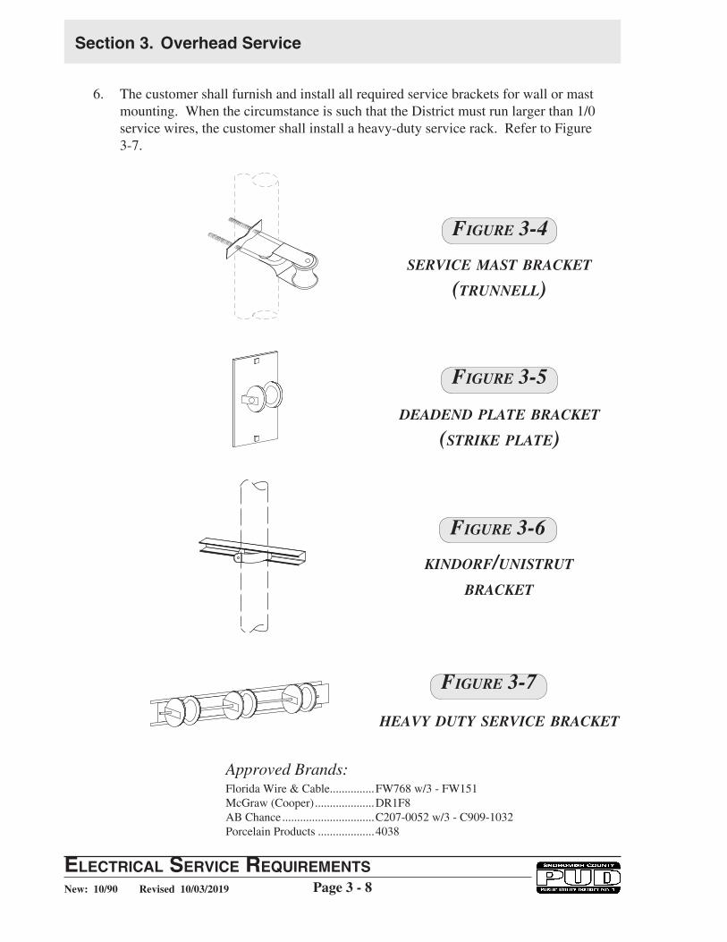
Approved Brands:Florida Wire & Cable ...............FW768 w/3 - FW151McGraw (Cooper) ....................DR1F8AB Chance ...............................C207-0052 w/3 - C909-1032Porcelain Products ...................4038
6. The customer shall furnish and install all required service brackets for wall or mast mounting. When the circumstance is such that the District must run larger than 1/0 service wires, the customer shall install a heavy-duty service rack. Refer to Figure 3-7.
Figure 3-4
Figure 3-5
fIgure 3-3Figure 3-6
fIgure 3-3Figure 3-7
SerViCe MAST brACkeT
(TruNNeLL)
deAdeNd PLATe brACkeT
(STrike PLATe)
kiNdOrF/uNiSTruT
brACkeT
heAVY duTY SerViCe brACkeT

ElEctrical SErvicE rEquirEmEntSPage 3 - 9
Section 3. Overhead Service
Revised 10/03/2019New: 10/90
7. The service mast shall consist of a minimum 2 inch rigid galvanized steel conduit and must have a lead ring or neoprene type flashing at the roof line. Two “U” bolts spaced at least 2 feet apart shall be required to attach all mast services. If a coupling is used, it must be located at least 3 feet below the wall plate and “U” bolts must be installed near the wall plate and as close to the top of the coupling or reducer as possible. There shall be no couplings above the plate unless the distance between the lower couplings and weatherhead exceeds 10 feet. In such situations, an additional guy attached immediately above the coupling shall be required. Refer to Figure 3-8, 3-9 and 3-10.
Note: Refer to State of Washington, Department of Labor and Industries, Electrical Inspection Division, Rules and Regulations for specifics on service mast installations, WAC 296-46B-230.
fIgure 3-3Figure 3-8
SurFACe MOuNT
SerViCe MAST brACkeT
(TruNNeLL)
deAdeNd PLATe brACkeT
(STrike PLATe)
kiNdOrF/uNiSTruT
brACkeT
heAVY duTY SerViCe brACkeT

Section 3. Overhead Service
ElEctrical SErvicE rEquirEmEntSPage 3 - 10Revised 10/03/2019New: 10/90
FLuSh MOuNT
fIgure 3-3Figure 3-9
NOTE: Mast guying or bracing is required if the mast exceeds 26 inches above the roof line or if the service drop is longer than 100 feet. WAC 296-46B-230.

ElEctrical SErvicE rEquirEmEntSPage 3 - 11
Section 3. Overhead Service
Revised 10/03/2019New: 10/90
45°
Collars, ''Cyclone'' fence orequal with 3/8'' min. bolts
3/4'' rigid steel galv. conduit withends flattend and drilled. Lowerend to have sharp bend with noradius.
1/4'' x 4'' x 4''galv. plate washer.
Customer ownedcondutor 18" Minimum.
PUDService Drop
Flashing
Secure conduit to rafterwith min. 5/6'' U-bolt.
8'' Min.
6'' Max.
PU
DP
UD
Guy attachment plateas detailed or equal.
Guy Attachment Plate Detail
Top View - Guys
2''
45°
1-1/2''
9/32'' hole
5/8''
1-1/4''
1/2'' hole
PullServiceDrop
ServiceBraces 60° to 90°apart andsymmetrical aboutthis centerline
Top View - Braces
PullDrop
NOTE: Mast guying or bracing is required if the mast exceeds 26 inches above the roof line or if the service drop is longer than 100 feet. WAC 296-46B-230.
Figure 3-10
guYiNg / brACiNg

Section 3. Overhead Service
ElEctrical SErvicE rEquirEmEntSPage 3 - 12Revised 10/03/2019New: 10/90
8. Non-metallic conduit may be used for service entrance conductors where the service bracket or other point of attachment for service drop conductors is not attached to the conduit and is on the outside lines of the building. Refer to Figure 3-11.
9. Where there is no problem with roof clearances, mast type services must have a minimum height of 18 inches extending above the roof to the point of attachment.
10. Approved metal strike plate, complete with insulator attached, shall have corrosion-resistant carriage bolts of not less then 3/8 inch diameter. Refer to Figure 3-11.
11. For a duplex or larger building where only one strike to the building is permitted but more than one weatherhead is desired, the weatherheads must terminate within 18 inches of each other.
Figure 3-11
MASTheAd WALL MOuNTiNg

ElEctrical SErvicE rEquirEmEntSPage 3 - 13
Section 3. Overhead Service
Revised 10/03/2019New: 10/90
12. Only three conduits per service entrance shall be used unless written permission is obtained from the District by using the District’s Variance Application. Refer to Section 2. Two of the masts shall be within 18 inches of the central mast attachment point.
13. Weatherheads are required on all overhead service conduits.
14. The practice of attaching a strike plate to the barge board and fanning the conductors above the edge of the roof to connect to a service mast will not be permitted. Strike plate attached directly to the roof is not acceptable.
15. Unfused service conductors within a building or structure shall be installed in metallic raceways, other than electrical metallic tubing, permitted in Section 230-43 of the NEC or in schedule 80 rigid non-metallic conduit. The raceway shall extend no more than 15 feet inside the building or structure. Reference WAC 296-46. Install conduit per NEC 300-4 requirements.
16. The District will run the secondary service and make permanent service connections, furnish and install meters.
17. Service masts, weatherheads and strike plates must be permanently and safely accessible. If a service mast cannot be reached by a District service truck then it must be located:
a. 17 feet or less above the ground or ladder base and less than 18 inches from the edge of the roof (refer to Figure 3-12),
Note: Ifaladderistobeusedtheremustbeafirm,levelsurfaceand enough clearance at the base of the ladder to allow a ratio of 4:1 (1 foot out from the top support or wall for every 4 foot in working length or height) or a 75-degree pitch for ladder safety.
Where the service insulator is 4 feet from the edge of the roof and 18 inches above the roof or 3 feet from the edge of the roof and not higher than 4 feet above the roof it may be worked from a ladder.
or
b. the the service insulator can not exceed 6 feet above the roof and the roof must be able to be walked on and worked on safely. Roofs not acceptable to the District are roofs with pitches 4:12 or greater and roofing that may be easily damaged like soft tile, metal, glass or fiberglass. Also, any roof that the District inspector considers unsafe, deteriorated or not structurally sound is unacceptable.

Section 3. Overhead Service
ElEctrical SErvicE rEquirEmEntSPage 3 - 14Revised 10/03/2019New: 10/90
18. WAC 296-155-24510 requires employees exposed to a hazard of falling from a location 10 feet or more in height to be protected by fall restraint, fall arrest systems or positioning device systems.
Due to the above requirement, in some cases, such as when a roof or shed extension has been added and the District can not reach the strike point either by ladder in compliance with current strike requirements, or by bucket truck, it will be necessary for the customer to install a new strike point and new conductor to allow the District to reach the location in compliance with current regulations and requirements. The customer will also need to secure an electrical inspection and approval of the work done from the appropriate jurisdiction before the District can make permanent connections at the new strike location. Refer to Figure 3-13.
When possible, and safety is not an issue, such as in the case of partial power, the District will temporarily leave the service energized to avoid disconnecting the service to the customer. However in some instances where a safety hazard exists, for example, a bad neutral, the District will need to immediately disconnect the service until such time as the customer has completed the necessary repairs and obtained the required approvals to reconnect the service. Coordination of the transfer of service or the connection of the new service will need to be arranged through the District’s Customer Engineering Department
Figure 3-12
MAST LOCATiON / ACCeSSibiLiTY

ElEctrical SErvicE rEquirEmEntSPage 3 - 15
Section 3. Overhead Service
Revised 10/03/2019New: 10/90
Figure 3-13
ALTerNATe MAST STrike LOCATiON
Section 3. Overhead Service
ElEctrical SErvicE rEquirEmEntSPage 3 - 16Revised 10/03/2019New: 10/90
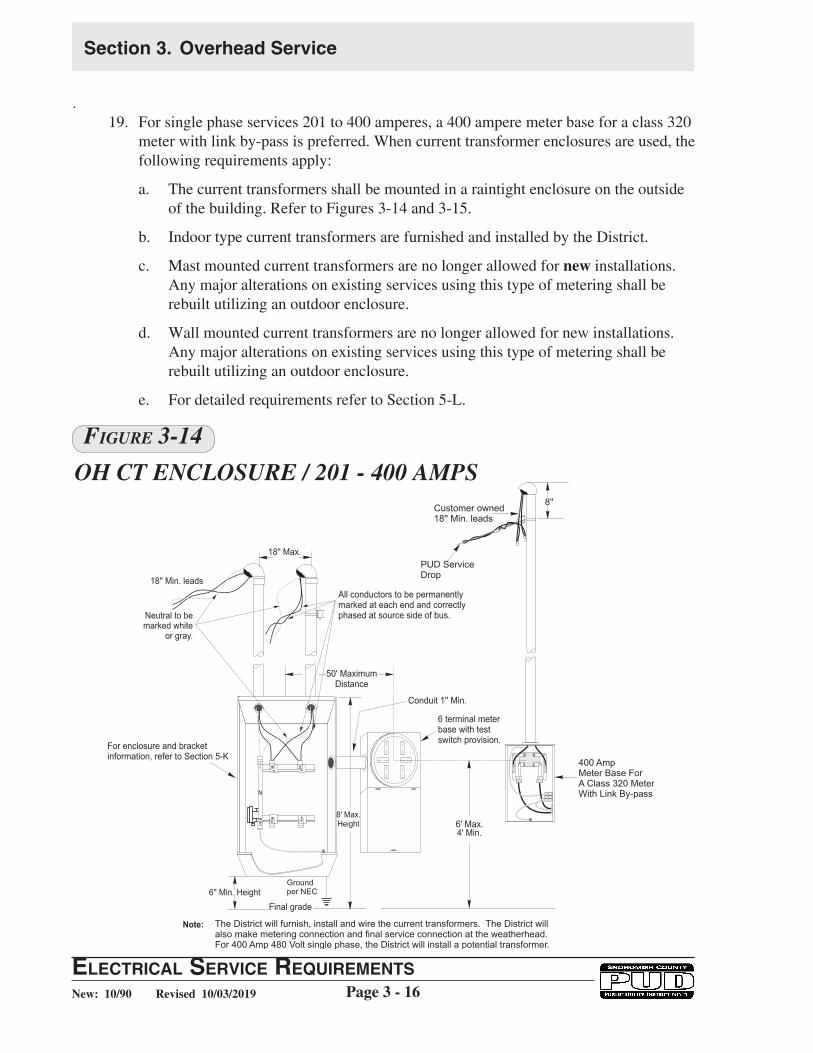
.19. For single phase services 201 to 400 amperes, a 400 ampere meter base for a class 320
meter with link by-pass is preferred. When current transformer enclosures are used, the following requirements apply:
a. The current transformers shall be mounted in a raintight enclosure on the outside of the building. Refer to Figures 3-14 and 3-15.
b. Indoor type current transformers are furnished and installed by the District.
c. Mast mounted current transformers are no longer allowed for new installations. Any major alterations on existing services using this type of metering shall be rebuilt utilizing an outdoor enclosure.
d. Wall mounted current transformers are no longer allowed for new installations. Any major alterations on existing services using this type of metering shall be rebuilt utilizing an outdoor enclosure.
e. For detailed requirements refer to Section 5-L.
Figure 3-14
Oh CT eNCLOSure / 201 - 400 AMPS

ElEctrical SErvicE rEquirEmEntSPage 3 - 17
Section 3. Overhead Service
Revised 10/03/2019New: 10/90
Figure 3-15Oh MAST SurFACe MOuNTiNg / 201 - 400 AMPS

Section 3. Overhead Service
ElEctrical SErvicE rEquirEmEntSPage 3 - 18Revised 10/03/2019New: 10/90
D. PRIMARY SERVICE - INDIVIDUAL RESIDENCE
(Refer Also to Sec. 2 Item N)
1. The plot plan provided by the customer will show the desired location for the service entrance and metering equipment (to be approved by the District prior to construction) and any special conditions affecting pole or wire locations. This includes objects such as wells, pools, hot tubs, utilities, buildings and driveways.
2. The District will design and install the complete overhead distribution system.
3. Clearing for Primary Lines on Private Property
a. The customer will provide and permanently maintain a road with adequate base and size to support the heavy equipment required for line construction and maintenance, adjacent to the poles, prior to construction.
b. The customer will remove all trees a minimum of 5 feet on each side of a proposed single phase line location or 10 feet on each side of a proposed three phase line, as staked by the District's engineer. Refer to Figure 3–16.
c. The customer will remove or top below the wire height leaning trees which the District representative constitutes as a potential hazard to the proposed line.
d. The customer will remove or top below the wire height all overhanging branches.
e. The customer will remove low growing trees, which by their location could in the future constitute a hazard to the proposed line.
f. The customer will remove debris that is hazardous to construction personnel.
4. The District will maintain tree trimming for existing primary lines.

ElEctrical SErvicE rEquirEmEntSPage 3 - 19
Section 3. Overhead Service
Revised 10/03/2019New: 10/90
After preparation for line extension.
PU
DPU
D
50'
1Ø3Ø
5' min.10' min. 10' min.5' min.
Figure 3-16CLeAriNg FOr Oh LiNe eXTeNSiONS
Before preparation for line extension.

Section 3. Overhead Service
ElEctrical SErvicE rEquirEmEntSPage 3 - 20Revised 10/03/2019New: 10/90
E. RESIDENTIAL PLAT & SUBDIVISION - LINE EXTENSION
1. The customer will advance cost of the line, including any special costs incurred in obtaining permits, easements or other documents, clearing or other special costs.
2. The District will design, install, own and maintain the complete overhead distribution system.
F. CONVENIENCE POLES
1. When requested by the customer for their specific benefit, the District may furnish and install a 35' convenience pole, with or without guying and anchoring, at the customer's expense.
2. Poles longer than 35 feet may be provided on an individual cost basis.
3. The customer shall advance the required fees prior to final engineering and construction.
4. The District shall install, own and maintain convenience poles.
G. SERVICE POLES
1. The District shall install, own and maintain service poles as necessary to provide adequate clearance and support of the service conductors.
H. METER POLES
1. When requested by the customer, the District may furnish and install a 35' meter pole, with or without guying and anchoring, at the customer's expense.
a. The customer shall provide an adequate road-like surface for the District's heavy equipment required for the installation of the pole.
b. The customer shall be liable for personnel injuries, vehicle damage and crew time loss caused by an inadequate access.
2. The meter pole will be the property of the customer.
3. The meter pole location shall have a minimum 10' horizontal clearance from the outermost point of any District equipment on the field (house) side. A minimum 15' clearance shall be provided on the road (access) side to allow for District vehicle access. See Figure 3-17 for an example of meter pole clearances.
4. When the meter pole is to be replaced, the customer shall, at his or her expense, transfer all customer-owned service entrance equipment to the new pole.
5. Permanent safe walking access shall be provided and maintained by the customer to meter poles that have District equipment on them, e.g., meter and service wires. Refer to Section 2-N.

ElEctrical SErvicE rEquirEmEntSPage 3 - 21
Section 3. Overhead Service
Revised 10/03/2019New: 10/90
6. Neither trees nor the District’s distribution or transmission poles shall be used as meter poles.
7. When a pole is used as a metering point and central distribution center and the conductors beyond the metering point are subject to contact with machinery, the customer is required to install a main disconnect switch on that pole.
Figure 3-17
15’ min clearance for PUD access
Meter Pole 10’ min clearance to outermost point of PUD structure
Meter Pole
Field (House) Side Road (Access) Side
MeTer POLe CLeArANCe(LOCATiON OF MeTer POLe)

Section 3. Overhead Service
ElEctrical SErvicE rEquirEmEntSPage 3 - 22Revised 10/03/2019New: 10/90
7. Meter poles shall be installed and sized to provide the clearances as detailed in Figures 3-3, 3-17, and 3-18.
8. Meter poles meeting District requirements may be customer furnished and installed.
9. Either cedar or fir poles may be used, provided fir poles are full length pressure treated, and cedar poles are butt treated in accordance with American Wood-Preservers' Association Standards.
MeTer POLe CLeArANCe(JOiNT OCCuPANCY)
Figure 3-18

ElEctrical SErvicE rEquirEmEntSPage 3 - 23
Section 3. Overhead Service
Revised 10/03/2019New: 10/90
10. Outer bark must be completely removed from all meter poles. The pole, with minimum requirements as listed below, shall be set at the proper depth and backfilled with rocks and soil. Backfill shall be tamped to provide a sound installation.
11. All wood meter poles shall have a 2" wide, 1/2" deep gain 12' up from bottom of pole.
12. Other than wood poles will be considered and evaluated on an individual basis. These poles shall have a gain identification mark or tag at 12' up from bottom of pole or as designated by the District.
13. Location and inspection of the meter pole shall be approved by a District representative prior to installation.
14. The customer is responsible for having the pole hole inspected by the District for proper depth. This inspection shall be made prior to setting the pole, after the hole is prepared and the meter pole is on site.
15. The District will not connect to any customer-installed meter pole that has not been inspected and accepted by the District.
16. The customer shall be responsible for anchoring/guying of a customer installed meter pole, to withstand the pull imposed by the District’s service conductors. A District Engineer will inform the customer if the pole requires anchoring and guying. An anchor and guy will typically be required for services over 125' or with an angle of 15° or more in the service run. The District will not connect to any meter pole that is unstable or in any way does not conform to this Standard.
17. The thru-bolt type insulator bracket installed by the customer shall be located 8" below and 45° from the weatherhead, facing the point of attachment to the District facilities. The insulator shall be mounted high enough above ground to provide adequate conductor to ground clearances for the District’s service drop. Refer to Figure 3-3 and 3-18.
18. Relocations of the meter pole may be done at the customer’s request on an individual cost basis.
Table 1 Meter Pole Specifications and Setting Depth
Pole Length Pole Class
Setting Depth
(Firm Soil)
Minimum Circumference 6’ from Butt Minimum
Circumference at Top Fir Cedar
20 ft 4 4’ 25” 27” 21”
25 ft 4 5’ 27.5” 30” 21”
30 ft 4 5’ 29.5” 32.5” 21”

Section 3. Overhead Service
ElEctrical SErvicE rEquirEmEntSPage 3 - 24Revised 10/03/2019New: 10/90
Figure 3-19
TYPiCAL MeTer POLe iNSTALLATiONS
District Service Wires
Pole Gain TypicalRefer to Sect. 3-H.
Groundper NEC
Groundper NEC
Groundper NEC
6''
6'6' 6'
12'
Schedule 40 or 80PVC or rigid steelconduit.
Customer Owned18'' Min. LeadsTypical
Customer OwnedPer NEC
Customer OwnedPer NEC
18''
12'' Max.8'' Min.
Meter SocketMeter Socket
Disconnectper
NEC
Disconnectper
NEC
48'' Min.72'' Max.
Neutral Bond
Setting Depthrefer to Table 1Sect. 3-H.
O/H - U/G O/H RV Svs. O/H - O/H
Neutral Bond

ElEctrical SErvicE rEquirEmEntSPage 3 - 25
Section 3. Overhead Service
Revised 10/03/2019New: 10/90
2' Max. 2' Max.
8'' 8''
Customer owned
18'' Min. leads
Customer owned
18'' Min. leads
PUD Service
Drop
PUD Service
Drop
3' Max. 3' Max.
400 Amp Meter Base for a class320 meter With Link By-pass
8' Max.
6" Min.
For enclosure and bracket
information see Section 5-K
6' Max.
4' Min.
6' Max.
4' Min.
Conduit 1'' Minimum
6 terminal raintight meter socketwith test switch provisions
When a pole is used as a metering point / central distribution center and the overhead conductors beyond the metering point are subject to contact with machinery, the customer is required by the State to install a main disconnect switch on the pole.
Approved ground per NEC
Customer OwnedPer NEC
Figure 3-20
19. Pole mounted current transformers are not allowed for new installations. Any major alterations on existing services using this type of metering shall be rebuilt utilizing a 400 amp rated meter socket for a class 320 meter or outdoor current transformer enclosure. Refer to Figure 3-20.
MeTer POLeS - OVer 200 AMP

Section 3. Overhead Service
ElEctrical SErvicE rEquirEmEntSPage 3 - 26Revised 10/03/2019New: 10/90
Figure 3-21
I. AREA LIGHT - OVERHEAD FEED - RESIDENTIAL
1. District Responsibilities:
a. Determine availability of service and coordinate the location of the area light with the customer.
b. There must be an existing transformer available to serve the light. If there is no existing transformer the District can install a transformer at the customer's expense.
c. Light will be placed on existing District wood poles only.
d. Poles may be set in areas of unrestricted public access, contact the District for information.
2. Customer Responsibilities:
a. Meet with District representative to determine availability of service and location of the area light.
b. Complete and sign (property owner only) Application to Contract with the District for Area Lighting Service Form No. 1008.
c. Provide access for the District's equipment for installation and maintenance.
ElEctrical SErvicE rEquirEmEntSPage 3 - 27
Section 3. Overhead Service
Revised 10/03/2019New: 10/90
J. MISCELLANEOUS POLE ATTACHMENTS
1. Pole Attachments prohibited for Utility Poles
RCW: 70.54.090 provides that:
"It shall be unlawful to attach to utility poles any of the following: Advertising signs, posters, vending machines, or any similar object which presents a hazard to, or endangers the lives of, electrical workers. Any attachment to utility poles shall only be made with the permission of the utility involved, and shall be placed not less than twelve feet above the surface of the ground."
a. The types of unlawful attachments shall include, but are not limited to neighborhood watch signage, lost pet signage, information or regulatory signage, banners, flags, mailboxes, basketball hoops or any similar objects.
b. It is the District's practice not to permit attachments to utility poles.
2. CATV - Power Supplies
a. Maximum size cabinet shall be 26'' wide x 36'' high x 16'' deep and weigh 500 pounds or less. The cabinet shall be 14 gauge metal painted to resist exposure and to prevent rust.
b. Battery pac auxiliary power supplies shall have batteries in the assembly which have flame arrestor vent caps and shall be protected from electrical spark by having separate metal containers. The battery containers and the cabinet shall be well vented.
c. The unit shall be designed to operate from connection to a 120 volt single phase District secondary. Its circuitry shall include a 15 amp 120 volt rated breaker and back-feed voltage protection to prevent power from the unit being routed into the District’s system.
d. The battery pac auxiliary power supply unit shall be stand-off mounted such that it is situated in-line with the lead of the pole line. There shall be a minimum 5 inches clearance between the power supply housing and the pole to which it is mounted.
e. The battery pac auxiliary power supply housing shall be effectively grounded to a grounding system installed by the cablevision company. Ground rod(s) shall be installed a minimum 18 inches from the base of the pole on which the power supply unit is mounted.
f. The Schedule 40 PVC service conduit, capped with a weatherhead, shall be mounted on face of pole and shall terminate 8 inches above the level of the District’s overhead secondary attachment or neutral position. Maximum conduit size is 1-1/2".
g. For standard mounting height, refer to Figure 3-22. Submittal of an “Application for Variance” is required.

Section 3. Overhead Service
ElEctrical SErvicE rEquirEmEntSPage 3 - 28Revised 10/03/2019New: 10/90
Figure 3-22
CATV POWer SuPPLieS
h. Only qualified District employees or District contractors shall connect auxiliary power supply unit service wires to the District secondary power lines.
i In the event that it is necessary to replace or relocate a pole on which an auxiliary power supply unit is mounted, the cablevision company shall transfer or relocate the unit at no cost to the District.
j. In addition to the standard attachment fee, the cablevision company shall pay the District a flat rate to cover the cost of providing electrical service to the auxiliary power supply unit.
3. Unmetered Power Source - refer to Figure 3-23 for materials.
Refer to the District’s Rate Schedule 23 for limited availability. This schedule is

ElEctrical SErvicE rEquirEmEntSPage 3 - 29
Section 3. Overhead Service
Revised 10/03/2019New: 10/90
available for nonmetered service to television cable amplifiers, air traffic warning lights, and other such applications where metering is deemed impractical by the District.
a. Contact the District for approval prior to installation.
b. The District must evaluate location, materials and equipment prior to installation.
c. Only one power source is allowed per pole.
d. Maximum power source shall be nominal 120 volt 20 amp GFCI protected double receptacle outlet.
e. Power source materials shall be evaluated prior to installation. All materials shall be UL approved for outdoor use.
f. The customer will provide an approved power source receptacle and District crews will install and provide power at customer’s expense.
g. Weatherhead shall be 8" above District's neutral/secondary position and receptacle shall not be mounted lower than 12' above the ground.
A
E
H
F
B
D G
C
Variable
Materials
A Single entrance PVC molded outlet box, type FSE.
B Weatherproof PVC receptable cover and gasket.
C GFCI* 20 Amp receptacle.
D 3/4'' PVC conduit straps, two required.
E Service entrance weatherhead, PVC.
F Maximum 3/4'' PVC.
G Galvanized steel nails or screws.
H Three No. 12 cu. THW or better wire. 1- black, 1 - white, and 1 - green. 18'' minimum length extending from weatherhead.
*GFCI - Ground Fault Current Interrupter
Figure 3-23uNMeTered POWer SOurCe
MATeriALS