SECTION 3 - Farnell element14 · Q 1.85 nom. 1.85 nom. .073 nom. R 0.50 nom. .020 nom. S 0.10 nom....
16
Our Most Important Connection is with You.™ Board-to-Board: MMBX / SMP-MAX SECTION 3 R223 / R222M
Transcript of SECTION 3 - Farnell element14 · Q 1.85 nom. 1.85 nom. .073 nom. R 0.50 nom. .020 nom. S 0.10 nom....

Our Most Important Connection is with You.™
Board-to-Board: MMBX / SMP-MAX
SECT
ION
3
R223 / R222M
3-3
Our Most Important Connection is with You.™
Go online for data sheets & assembly instructions. Visit www.radiall.com and enter the part number.
MMBX
Introduction . . . . . . . . . . . . . . . . . . . . . . . . . . . . . . . . . . . . . . . . . . . . . . . . . . . . . . . . . . . . . . . . . . . . . . . . . . . . . . . . . . . . . . . . . . . . . . . . . . . . . . . . . . . . . . . . . . . . . 3-4Interface . . . . . . . . . . . . . . . . . . . . . . . . . . . . . . . . . . . . . . . . . . . . . . . . . . . . . . . . . . . . . . . . . . . . . . . . . . . . . . . . . . . . . . . . . . . . . . . . . . . . . . . . . . . . . . . . . . . . . . . . . 3-5Characteristics . . . . . . . . . . . . . . . . . . . . . . . . . . . . . . . . . . . . . . . . . . . . . . . . . . . . . . . . . . . . . . . . . . . . . . . . . . . . . . . . . . . . . . . . . . . . . . . . . . . . . . . . . . . . . . . . . 3-6Plugs . . . . . . . . . . . . . . . . . . . . . . . . . . . . . . . . . . . . . . . . . . . . . . . . . . . . . . . . . . . . . . . . . . . . . . . . . . . . . . . . . . . . . . . . . . . . . . . . . . . . . . . . . . . . . . . . . . . . . . . . . . . . 3-7PCB receptacles . . . . . . . . . . . . . . . . . . . . . . . . . . . . . . . . . . . . . . . . . . . . . . . . . . . . . . . . . . . . . . . . . . . . . . . . . . . . . . . . . . . . . . . . . . . . . . . . . . . . . . . . . 3-7 to 3-8Adapters . . . . . . . . . . . . . . . . . . . . . . . . . . . . . . . . . . . . . . . . . . . . . . . . . . . . . . . . . . . . . . . . . . . . . . . . . . . . . . . . . . . . . . . . . . . . . . . . . . . . . . . . . . . . . . . . . . . . . . . . . 3-9Demo board . . . . . . . . . . . . . . . . . . . . . . . . . . . . . . . . . . . . . . . . . . . . . . . . . . . . . . . . . . . . . . . . . . . . . . . . . . . . . . . . . . . . . . . . . . . . . . . . . . . . . . . . . . . . . . . . . . . . 3-10Panel drilling . . . . . . . . . . . . . . . . . . . . . . . . . . . . . . . . . . . . . . . . . . . . . . . . . . . . . . . . . . . . . . . . . . . . . . . . . . . . . . . . . . . . . . . . . . . . . . . . . . . . . . . . . . . . . . . . . . . 3-10Assembly instructions . . . . . . . . . . . . . . . . . . . . . . . . . . . . . . . . . . . . . . . . . . . . . . . . . . . . . . . . . . . . . . . . . . . . . . . . . . . . . . . . . . . . . . . . . . . . . . . . . . . . . . . . . 3-10
SMP-MAXIntroduction . . . . . . . . . . . . . . . . . . . . . . . . . . . . . . . . . . . . . . . . . . . . . . . . . . . . . . . . . . . . . . . . . . . . . . . . . . . . . . . . . . . . . . . . . . . . . . . . . . . . . . . . . . . 3-11 to 3-12Characteristics . . . . . . . . . . . . . . . . . . . . . . . . . . . . . . . . . . . . . . . . . . . . . . . . . . . . . . . . . . . . . . . . . . . . . . . . . . . . . . . . . . . . . . . . . . . . . . . . . . . . . . . . . . . . . . . . . 3-13Jacks and plugs . . . . . . . . . . . . . . . . . . . . . . . . . . . . . . . . . . . . . . . . . . . . . . . . . . . . . . . . . . . . . . . . . . . . . . . . . . . . . . . . . . . . . . . . . . . . . . . . . . . . . . . . . . . . . . . . 3-14Receptacles . . . . . . . . . . . . . . . . . . . . . . . . . . . . . . . . . . . . . . . . . . . . . . . . . . . . . . . . . . . . . . . . . . . . . . . . . . . . . . . . . . . . . . . . . . . . . . . . . . . . . . . . . . . . 3-15 to 3-16Adapters and Panel drilling . . . . . . . . . . . . . . . . . . . . . . . . . . . . . . . . . . . . . . . . . . . . . . . . . . . . . . . . . . . . . . . . . . . . . . . . . . . . . . . . . . . . . . . . . . 3-16 to 3-17
SECT
ION
3 T
ABLE
OF
CON
TEN
TS
Contents
3-4
Our Most Important Connection is with You.™
Go online for data sheets & assembly instructions. Visit www.radiall.com and enter the part number.
MM
BXIntroduction
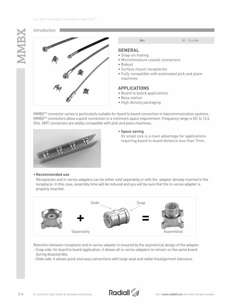
• Space saving Its small size is a main advantage for applications requiring board to board distance less than 7mm.
• Recommended use Receptacles and in-series adapters can be either sold separately or with the adapter already inserted in the receptacle. In this case, assembly time will be reduced and you will be sure that the in-series adapter is properly inserted.
Retention between receptacle and in-series adapter is ensured by the asymetrical design of the adapter.- Snap side: for board to board application, it allows all in-series adapters to remain on the same board during disassembly.- Slide side: it allows quick and easy connections with large axial and radial misalignment tolerance.
+Separately
Slide Snap
Assembled
GENERAL• Snap-on mating• Microminiature coaxial connectors• Robust• Surface mount receptacles• Fully compatible with automated pick and place
machines APPLICATIONS• Board to board applications• Base station• High density packaging
MMBXTM connector series is particularly suitable for board to board connection in telecommunication systems. MMBXTM connectors allow a quick connection in a minimum space requirement. Frequency range is DC to 12.4 GHz. SMT connectors are totally compatible with pick and place machines.
50Ω DC - 12.4 GHz
=
3-5
Our Most Important Connection is with You.™
Go online for data sheets & assembly instructions. Visit www.radiall.com and enter the part number.
MM
BX
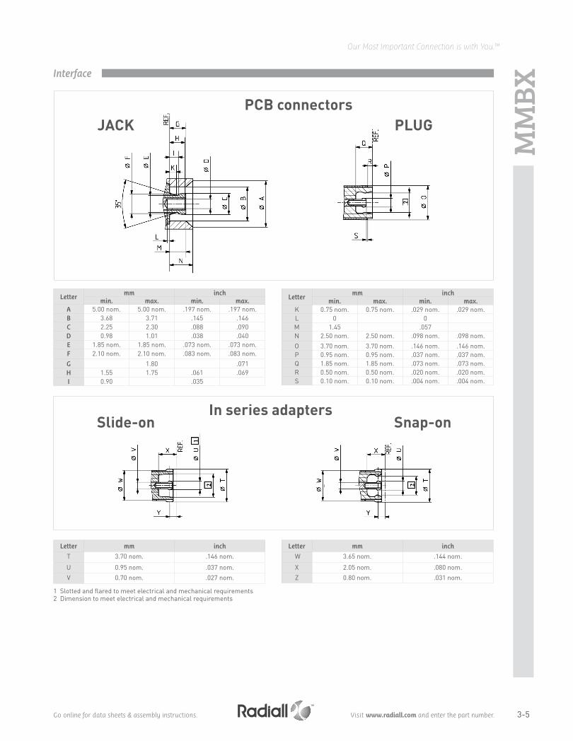
Interface
1 Slotted and flared to meet electrical and mechanical requirements 2 Dimension to meet electrical and mechanical requirements
JACKPCB connectors
PLUG
Letter mm inch
min. max. min. max. A 5.00 nom. 5.00 nom. .197 nom. .197 nom.B 3.68 3.71 .145 .146C 2.25 2.30 .088 .090D 0.98 1.01 .038 .040E 1.85 nom. 1.85 nom. .073 nom. .073 nom.F 2.10 nom. 2.10 nom. .083 nom. .083 nom.G 1.80 .071H 1.55 1.75 .061 .069I 0.90 .035
Letter mm inch
T 3.70 nom. .146 nom.
U 0.95 nom. .037 nom.V 0.70 nom. .027 nom.
Letter mm inch
W 3.65 nom. .144 nom.
X 2.05 nom. .080 nom.Z 0.80 nom. .031 nom.
Letter mm inch
min. max. min. max. K 0.75 nom. 0.75 nom. .029 nom. .029 nom.L 0 0M 1.45 .057N 2.50 nom. 2.50 nom. .098 nom. .098 nom.O 3.70 nom. 3.70 nom. .146 nom. .146 nom.P 0.95 nom. 0.95 nom. .037 nom. .037 nom.Q 1.85 nom. 1.85 nom. .073 nom. .073 nom.R 0.50 nom. 0.50 nom. .020 nom. .020 nom.S 0.10 nom. 0.10 nom. .004 nom. .004 nom.
Slide-onIn series adapters
Snap-on

3-6
Our Most Important Connection is with You.™
Go online for data sheets & assembly instructions. Visit www.radiall.com and enter the part number.
MM
BXCharacteristics
All dimensions are given in mm.Standard packaging = 100 pieces.
ELECTRICAL CHARACTERISTICS Impedance 50Ω
Frequency range DC - 12.4 GHz
Typical V.S.W.R. • Straight connectors:
- 2/50/S - 2.6/50/S - 2.6/50/D
• Right angle connectors: - 2/50/S- 2.6/50/S - 2.6/50/D
DC - 1 GHz
1.05 1.05 1.05
1.05 1.05 1.05
1 - 2.5 GHz
1.06 1.06 1.06
1.13 1.06 1.06
2.5 - 6 GHz
1.10 1.10 1.10
1.22 1.17 1.13
Insulation resistance › 1 GΩ
Dielectric withstanding voltage (sea level)• 2.50 • 2.6/50
4.4.5500 Vrms. 50 Hz750 Vrms. 50 Hz
Contact resistance• Center contact • Outer contact
4.4.24.4.3
≤ 5 mΩ≤ 1 mΩ
MECHANICAL CHARACTERISTICSMechanical endurance 4.7.1 100 matings
Engagement and separation force• Engagement • Separation
4.5.4
30 N max8-30 N
Contact captivation 4.5.2 ≥ 10 NCable retention force
• 2/50 • 2.6/50
58 N
110 NVibration 4.6.3 - IEC 68-2-6 Fc MIL-STD-202, Method 204 D, condition A
ENVIRONMENTAL CHARACTERISTICS Temperature range -55°C + 155°C
Thermal shock 4.6.7 - IEC 68-2-14 Na MIL STD 202, method 107G, condition B1
Moisture resistance 4.6.6 - IEC 68-2-3 Ca MIL STD 202, method 106F
Corrosion 4.6.10 - IEC 68-2-11 Ka MIL STD 202, method 101, condition B
Vibration 4.6.3 - IEC 68-2-6 Fc MIL STD 202, method 204D, condition A
MATERIALS Center & outer contacts Beryllium copper
Bodies Brass
Ferrules Copper
Insulators PTFE
PLATING Center & outer contacts Gold/NPGR
Bodies NPGR
Ferrules NPGR
Test / Characteristics CECC 22000 Values / Remarks

3-7
Our Most Important Connection is with You.™
Go online for data sheets & assembly instructions. Visit www.radiall.com and enter the part number.
MM
BX
Plugs and PCB receptacles
STRAIGHT PLUGS (male center contact)
RIGHT ANGLE PLUGS (male center contact)
STRAIGHT PCB RECEPTACLES WITH PRE-ASSEMBLED ADAPTER (male center contact)
Cable group Cable group dia. Part number Fig. A Captive center contact Note
RG178 / RG196 2/50/S R223 081 0001
14.3
yes
Crimp type for flexible cables
RG174 / RG316 2.6/50/S R223 082 00014.5
RG316 2.6/50/D R223 083 000
RG405 .085" R223 062 000 2 Solder type for semi-rigid cables
Cable group Cable group dia. Part number Fig. A Captive center contact Note
RG178 / RG196 2/50/S R223 181 0001
yes
Crimp type for flexible cablesRG174 / RG316 2.6/50/S R223 182 000
RG316 2.6/50/D R223 183 000
RG405 .085" R223 162 000 2 2.275 Solder type for semi-rigid cables
Fig. 1
Fig. 1
Fig. 2
Fig. 2
A
Fig. 1 Fig. 2
Part number Fig. Captive center contact PCB Assembly instructions Packaging Note
R223 434 0001
yes
M01Bulk 100 pieces
SMTR223 434 800 Tape & Reel 750 pieces
R223 435 000 2P01 Bulk 100 pieces
R223 435 010 3
Fig. 3

3-8
Our Most Important Connection is with You.™
Go online for data sheets & assembly instructions. Visit www.radiall.com and enter the part number.
MM
BXPCB receptacles
Fig. 1 Fig. 3 Fig. 4
Part number Fig. Captive center contact PCB Assembly instructions Packaging Note
R223 424 0001
yes
M01Bulk 100 pieces
SMTR223 424 800
Tape & Reel 750 piecesR223 424 870 4 M02 Catcher's mitt
R223 425 0002
P01
Bulk 100 pieces
R223 425 800Tape & Reel 500 pieces
R223 425 810 3 Catcher's mitt
EDGE CARD PCB RECEPTACLES (female center contact)
STRAIGHT PCB RECEPTACLES (female center contact)
SCREW-ON RECEPTACLE (female center contact)
Part number Captive center contact Packaging Note
R223 423 010yes
Bulk 100 piecesSMT
R223 423 800 Tape & Reel 650 pieces
Part number Captive center contact Panel drilling
R223 555 000 yes P02
Fig. 2

3-9
Our Most Important Connection is with You.™
Go online for data sheets & assembly instructions. Visit www.radiall.com and enter the part number.
MM
BX
Adapters
Part number Fig. Length A (mm) Type Nominal board to board distance
R223 703 180
1
4.8 Snap-slide 6.7
R223 703 020 9.7 Slide-slide 11.7
R223 703 040 12
Snap-slide
14
R223 703 080 7 9
R223 703 230 20.4 22.4
R223 720 020 2 13.6 Slide-slideBulkhead -
IN SERIES ADAPTERS (male-male center contact)
Fig. 1 Fig. 3
Fig. 4 Fig. 5
Part number Fig. Series Packaging
R191 389 100 1 MMBX male/SMA male
UnitR191 389 200 2 MMBX male/SMA female
R191 389 300 3 MMBX female/SMA male
R191 389 400 4 MMBX female/SMA female
R191 560 000 5 SMP-MAX female/MMBX male snap Bulk 100 pieces
BETWEEN-SERIES ADAPTERS
Other lengths available, please contact us.
Fig. 2
Other configurations available, with flange, straigt and right angle. Please contact us.
Fig. 1
Fig. 2
3-10
Our Most Important Connection is with You.™
Go online for data sheets & assembly instructions. Visit www.radiall.com and enter the part number.
MM
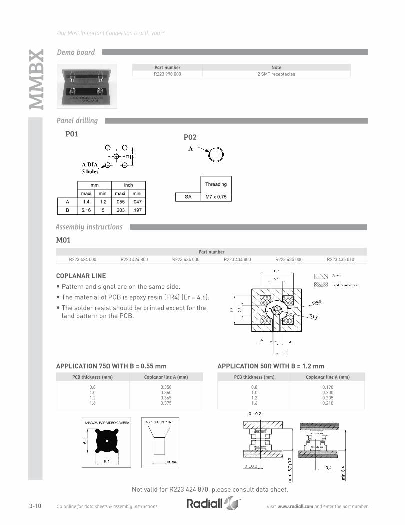
BXDemo board
Part number NoteR223 990 000 2 SMT receptacles
mm inch
maxi mini maxi mini
A 1.4 1.2 .055 .047
B 5.16 5 .203 .197
P01
Threading
ØA M7 x 0.75
P02
Panel drilling
Assembly instructions
Part number
R223 424 000 R223 424 800 R223 434 000 R223 434 800 R223 435 000 R223 435 010
M01
COPLANAR LINE
• Pattern and signal are on the same side.
• The material of PCB is epoxy resin (FR4) (Er = 4.6).
• The solder resist should be printed except for the land pattern on the PCB.
APPLICATION 75Ω WITH B = 0.55 mm APPLICATION 50Ω WITH B = 1.2 mmPCB thickness (mm) Coplanar line A (mm)
0.81.01.21.6
0.3500.3600.3650.375
PCB thickness (mm) Coplanar line A (mm)
0.81.01.21.6
0.1900.2000.2050.210
Not valid for R223 424 870, please consult data sheet.

3-11
Our Most Important Connection is with You.™
Go online for data sheets & assembly instructions. Visit www.radiall.com and enter the part number.
The Best SystemsRadiall’s engineers work with your engineers, allowing us to develop the best competitively priced misalignment RF coaxial interconnect solutions on the market today.
The Best ChoicesRadiall offers more board to board choices with four different product groups and ten connector series, that can address the most demanding wireless telecom applications required for the new generation of infrastructure compact equipment. From base stations to repeaters and even handheld and GPS devices, we have a tailored connector solution for you, including the new SMP-MAX, SMP-Spring, IMP-Spring and other large, limited and no misalignment solutions.
SMP-MAXGet the best for less with the new SMP-MAX large misalignment solution. Its patented impedance matching insulator is optimized for a larger operating gap between connectors making it easier for engineers to handle a board-to-board distance tolerance of at least .078” (2.0 mm) without a spring, which is 300% more than the standard SMP. It features a 3° minimum tilt (radial travel) and it has an operating frequency range of DC-6 GHz and a 1.2 max VSWR guaranteed at DC-3 GHz.
Spring-loaded Connectors Radiall’s one connector IMP-Spring and three connector SMP-Spring, MMBX-Spring, and BMR-Spring large misalignment spring-loaded series are the best for increased maximum distance tolerances. IMP-Spring is a cost effective, unique one connector solution that offers up to .023" (.6 mm) board to board distance tolerance with a tilt (radial travel) up to 4.5°. The new SMP-Spring and MMBX-Spring offer up to .078” (2 mm) board-to-board distance tolerance and a 4.5° tilt (radial travel). All spring-loaded solutions feature consistent VSWR and low RF leakage.
Limited MisalignmentRadiall's one connector IMP and three connector SMP and MMBX limited misalignment series are designed for applications requiring relatively precise distance tolerance of up to .023" (.6 mm) with a tilt (radial travel) of up to 4.5°.
No MisalignmentRadiall’s MMT, MMS and MCX series are designed for applications requiring little or no distance tolerance between boards.
SMP-MAX Receptacle
IMP
SMP-MAX Adapter
IMP-Spring and SMP-Spring
Board-to-Board solutions
SMP-
MA
XIntroduction

3-12
Our Most Important Connection is with You.™
Go online for data sheets & assembly instructions. Visit www.radiall.com and enter the part number.
GENERAL• Microminiature coaxial connectors • Power up to 300 Watts • Board to board distance misalignment of
at least 0.078’’ (2.0 mm)• Tilt (radial misalignment): 3° minimum• 1.2 max VSWR at DC - 3 GHz APPLICATIONS• Broadcast• RF components (filters, amplifiers, ….)• Wireless communications
50Ω DC - 6 GHz
The cost-effective solution for maximum mechanical misalignmentOf the several RF connectors available for interconnections in wireless remote radio heads, repeaters, base stations, GPS devices, and similar applications, the board-to-board style connector is growing in popularity. The product line has evolved from accommodating limited misalignment to offering the widest tolerances available.
SMP-MAX was introduced by Radiall to provide larger misalignment tolerances than the early version board-to-board connectors like SMP or SMP-spring while offering lower cost.
Featuring an optimized interface, SMP-MAX can work up to 6 GHz board-to-board distance misalignment at least 2.0 mm and radial misalignment 3° minimum.
The SMP-MAX series offers 2 levels of retention provided by the receptacles:• Slide-on, for the lowest retention• Snap-on, for a positive locking with a retention
A complete SMP-MAX board-to-board system is made of 3 parts:
Many other custom configurations are available. Larger distance misalignment and larger tilt versions are also available.
SMP-MAX Slide-on receptacle SMP-MAX In series adapter SMP-MAX Snap-on receptacle
SMP-
MA
X Introduction

3-13
Our Most Important Connection is with You.™
Go online for data sheets & assembly instructions. Visit www.radiall.com and enter the part number.
ELECTRICAL CHARACTERISTICS Impedance 50ΩFrequency DC - 6 GHz
Typical V.S.W.R.(Board to Board connection)
Misalignment DC - 3 GHz 3-6 GHzRadial 0°, Axial 0 mm < 1.15 < 1.25
Radial 0°, Axial +/- 1 mm < 1.20 < 1.35Radial 3°, Axial 0 mm < 1.15 < 1.25
Radial 3°, Axial +/- 1 mm < 1.20 < 1.35
Insertion loss(Board to Board connection)
Misalignment DC - 3 GHz 3-6 GHzRadial 0°, Axial 0 mm 0.10 0.15
Radial 0°, Axial +/- 1 mm 0.12 0.25Radial 3°, Axial 0 mm 0.10 0.15
Radial 3°, Axial +/- 1 mm 0.12 0.25Insulation resistance 5000 MΩCenter contact resistance < 3 mΩOuter contact resistance < 1.5 mΩWorking voltage 330 VRMSDielectric withstanting voltage 1000 VRMS
Power handling (typical)> 300W @ 2.7 GHz, 25°C> 200W @ 2.7 GHz, 85°C
RF leakage -70dB to 3 GHz, axial misalignment 0mm
MECHANICAL CHARACTERISTICSMating cycles 100 cycles
Slide-on Snap-onEngagement force < 14 N < 45 NDisengagement force < 9 N > 9, < 45 NCenter contact retention force > 7 NMinimum distance between PCB 13 mmRadial misalignment tolerance 3°min
Axial misalignment tolerance2.0 mm
Larger axial misalignment version available
ENVIRONMENTAL CHARACTERISTICS Temperature range -55°C / +165°CThermal shock MIL-STD-202, method 107, condition BVibration MIL-STD-202, method 204, condition BShock MIL-STD-202, method 213, condition ACorrosion salt spray MIL-STD-202, method 101, condition BMoisture resistance MIL-STD-202, method 106
MATERIALS Body Brass / Beryllium copperMale center contact BrassFemale center contact Beryllium copperGasket Silicon rubberInsulator PTFE / PEEK
PLATING Body NPGR / BBRMale center contact NPGRFemale center contact NPGR
Test / Characteristics Values / Remarks
Packaging = 100 pieces box / 500 pieces reel.All dimensions are given in mm.
Characteristics
SMP-
MA
X
3-14
Our Most Important Connection is with You.™
Go online for data sheets & assembly instructions. Visit www.radiall.com and enter the part number.
SMP-
MA
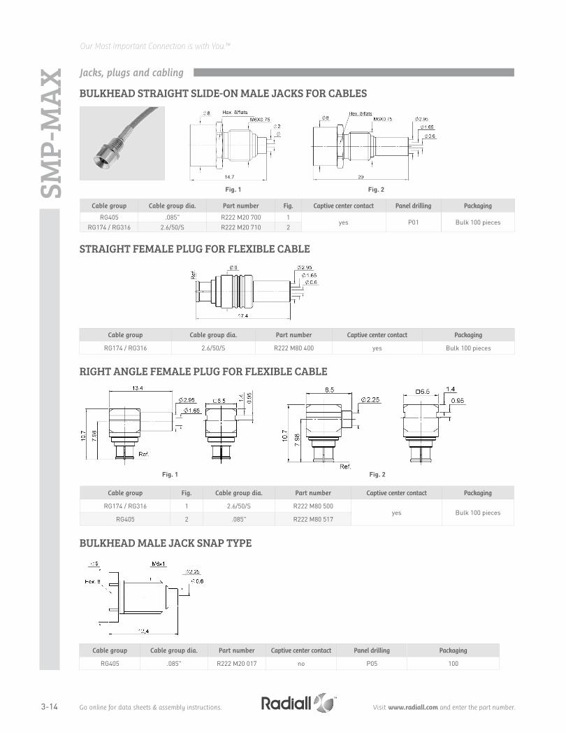
XBULKHEAD STRAIGHT SLIDE-ON MALE JACKS FOR CABLES
Cable group Cable group dia. Part number Fig. Captive center contact Panel drilling Packaging
RG405 .085" R222 M20 700 1yes P01 Bulk 100 pieces
RG174 / RG316 2.6/50/S R222 M20 710 2
Fig. 1 Fig. 2
Jacks, plugs and cabling
STRAIGHT FEMALE PLUG FOR FLEXIBLE CABLE
Cable group Cable group dia. Part number Captive center contact Packaging
RG174 / RG316 2.6/50/S R222 M80 400 yes Bulk 100 pieces
RIGHT ANGLE FEMALE PLUG FOR FLEXIBLE CABLE
Cable group Fig. Cable group dia. Part number Captive center contact Packaging
RG174 / RG316 1 2.6/50/S R222 M80 500yes Bulk 100 pieces
RG405 2 .085" R222 M80 517
Fig. 1 Fig. 2
BULKHEAD MALE JACK SNAP TYPE
Cable group Cable group dia. Part number Captive center contact Panel drilling Packaging
RG405 .085" R222 M20 017 no P05 100

3-15
Our Most Important Connection is with You.™
Go online for data sheets & assembly instructions. Visit www.radiall.com and enter the part number.
STRAIGHT SLIDE-ON MALE RECEPTACLES
Part number Fig. Dimensions (mm) Captive center contact Panel drilling Packaging Note
A B CR222 M00 700 1
yes
Tape & Reel 500 pieces SMTR222 M00 720
27.5 1.9 8.3 P02
Bulk 100 piecesSolder legs
R222 M00 770 8.4 3.4 10 Center contact dia. 0.95R222 M00 730 4 7.7 1.9 8.3 P03 Tape & Reel 400 pieces PIH + SMT, with capR222 M00 740 3 Tape & Reel 500 pieces SMTR222 M10 700 5 5.6 2 9 P01
Bulk 100 pieces
Screw-onR222 M10 730 6 P04 Press inR222 M10 750 5 5.6 4 10.5 P01R222 M00 790 4 13.3 1.9 12 P03 PIH + SMTR222 M00 860
27.3 3.5
10 P02Solder legs
R222 M00 880 7.7 2.4R222 M00 890 4 7.2 1.7 PIH + SMTR222 M03 700
77.6 0 10.2 500 Composite catcher's mitt / SMT
R222 M03 880 7.7 2.4 10 P02 Bulk 100 pieces Composite catcher's mitt / Solder legs
Fig. 1 Fig. 3
Receptacles
Fig. 6Fig. 5
Fig. 2 Fig. 4
SMP-
MA
X
Fig. 7
3-16
Our Most Important Connection is with You.™
Go online for data sheets & assembly instructions. Visit www.radiall.com and enter the part number.
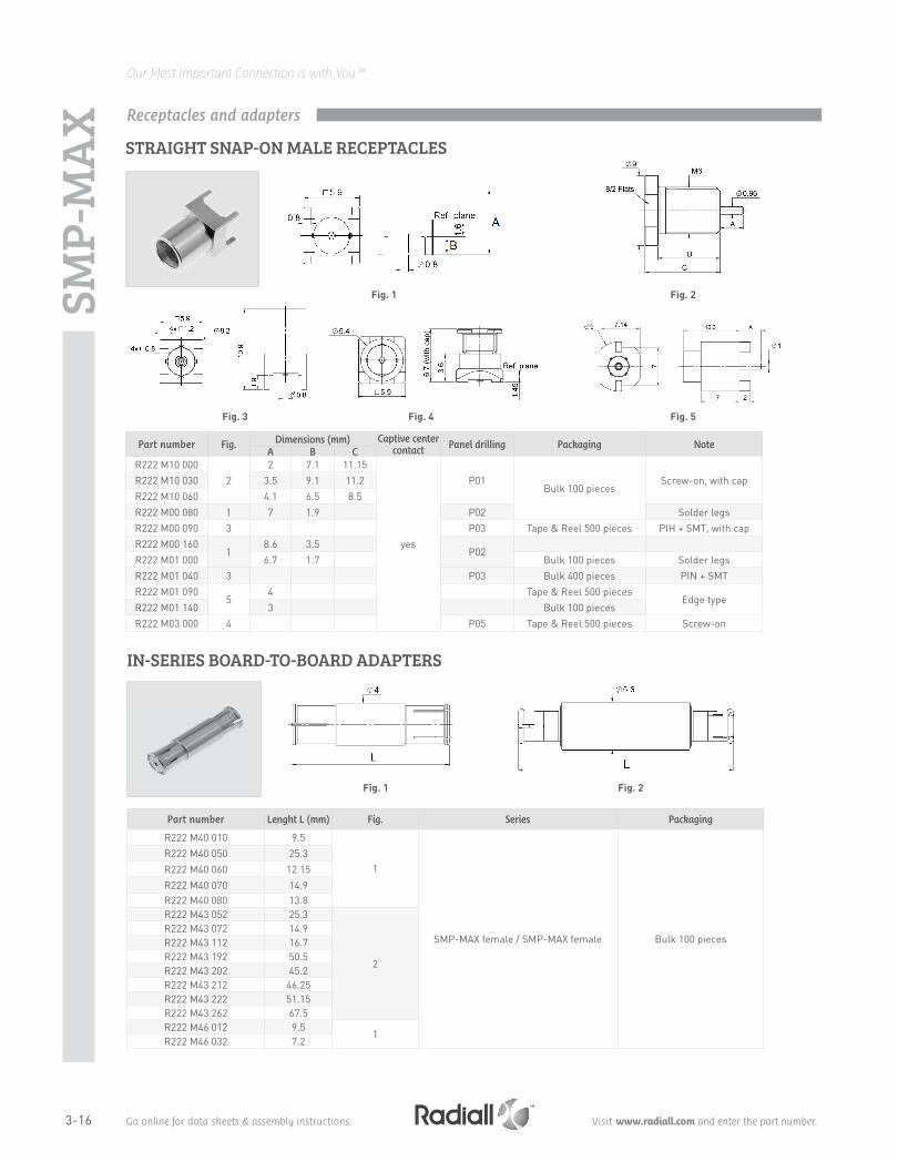
Part number Fig. Dimensions (mm) Captive center contact Panel drilling Packaging Note
A B CR222 M10 000
22 7.1 11.15
yes
P01Bulk 100 pieces
Screw-on, with capR222 M10 030 3.5 9.1 11.2R222 M10 060 4.1 6.5 8.5R222 M00 080 1 7 1.9 P02 Solder legsR222 M00 090 3 P03 Tape & Reel 500 pieces PIH + SMT, with capR222 M00 160
18.6 3.5
P02R222 M01 000 6.7 1.7 Bulk 100 pieces Solder legsR222 M01 040 3 P03 Bulk 400 pieces PIN + SMTR222 M01 090
54 Tape & Reel 500 pieces
Edge typeR222 M01 140 3 Bulk 100 piecesR222 M03 000 4 P05 Tape & Reel 500 pieces Screw-on
SMP-
MA
X
IN-SERIES BOARD-TO-BOARD ADAPTERS
Receptacles and adapters
Fig. 1 Fig. 2
Part number Lenght L (mm) Fig. Series Packaging
R222 M40 010 9.5
1
SMP-MAX female / SMP-MAX female Bulk 100 pieces
R222 M40 050 25.3R222 M40 060 12.15R222 M40 070 14.9R222 M40 080 13.8R222 M43 052 25.3
2
R222 M43 072 14.9R222 M43 112 16.7R222 M43 192 50.5R222 M43 202 45.2R222 M43 212 46.25R222 M43 222 51.15R222 M43 262 67.5R222 M46 012 9.5
1R222 M46 032 7.2
STRAIGHT SNAP-ON MALE RECEPTACLES
Fig. 2
Fig. 3
Fig. 1
Fig. 4 Fig. 5

3-17
Our Most Important Connection is with You.™
Go online for data sheets & assembly instructions. Visit www.radiall.com and enter the part number.
BETWEEN-SERIES BOARD-TO-BOARD ADAPTERS
Part number Lenght L (mm) Series Packaging
R191 996 110 12.6SMP-MAX female / SMP female
Bulk 100 piecesR191 996 130 8.9R191 560 000 7.5 SMP-MAX female / MMBX male snap
Fig. 1 Fig. 2
BETWEEN-SERIES ADAPTERS
Part number Fig. Series Packaging
R191 552 000 1 SMP-MAX male / SMA femaleUnit
R191 553 000 2 SMP-MAX female / SMA female
P01 P02 P03
P04
mm A M6x0.75
A
Panel drilling
P05
Receptacles
SMP-
MA
X