SECTION 15961B 09... · Web viewit will be difficult to route pneumatic tubing to locations where...
73
SECTION 23 09 93 SEQUENCE OF OPERATION FOR HVAC CONTROLS BASED ON DFD MASTER SPECIFICATION DATED 2/8/2018 This section has been written to provide direction for developing the sequence of operation for Division 23 controls. Depending on the requirements of your specific project, you may have to add, delete items, or modify what is currently written. The Division of Facilities Development expects changes and comments from you and encourages feedback on the control strategies contained herein. This Section will likely be added to and changed frequently - check for updates often. Where [brackets] are used, this indicates a choice needs to be made by the designer. Do NOT leave these choices up to the contractor. FOR PRELIMINARY REVIEW, DO NOT INCLUDE DELETED (STRICKEN) TEXT IN THIS SECTION. ONLY PROVIDE ACTUAL SEQUENCES TO BE USED FOR THE PROJECT. P A R T 1 - G E N E R A L SCOPE This section includes control sequences for HVAC equipment as well as equipment furnished by others that may need monitoring or control. Included are the following topics: PART 1 - GENERAL Scope Related Work Description of Work Submittals Operation and Maintenance Data Design Criteria PART 2 - PRODUCTS Not Applicable PART 3 - EXECUTION List Control Sequences Contained Herein General Control Heat Exchanger Control Heating Water Pump Control Central Chiller Plant Control Campus Chilled Water Building Tertiary Pump Control Terminal Unit Control – Pneumatic Terminal Unit Control – DDC and Electric Laboratory Terminal Unit Control Primary Humidifier Control Booster Humidifier Control Heat Wheel Control Variable Volume Mixed Air Handling Unit Control Single Zone Variable Volume Mixed Air Handling Unit Control Constant Volume Mixed Air Handling Unit Control Lab Exhaust Fan Control Heat Recovery System Control Mechanical / Electrical Room Ventilation Control Functional Performance Testing RELATED WORK Applicable provisions of Division 1 govern work under this Section. Section 01 91 01 or 01 91 02 – Commissioning Process Section 23 08 00 – Commissioning of HVAC Select the following DDC section utilized on this project. Section [23 09 24 or 23 09 23] - Direct Digital Controls (DDC) Section 23 09 14 - Pneumatic and Electric Controls DFD Project No. 00X0X 23 09 93-1 1 2 3 4 5 6 7 8 9 10 11 12 13 14 15 17 18 19 20 21 22 23 24 25 26 27 28 29 30 31 32 33 34 35 36 37 38 39 40 41 42 43 44 45 46 47 48 49 50 51 52 53 54 55 56 57 58 59 60 61 62 1 2
-
Upload
truongthuan -
Category
Documents
-
view
216 -
download
3
Transcript of SECTION 15961B 09... · Web viewit will be difficult to route pneumatic tubing to locations where...

SECTION 23 09 93SEQUENCE OF OPERATION FOR HVAC CONTROLS
BASED ON DFD MASTER SPECIFICATION DATED 2/8/2018
This section has been written to provide direction for developing the sequence of operation for Division 23 controls. Depending on the requirements of your specific project, you may have to add, delete items, or modify what is currently written. The Division of Facilities Development expects changes and comments from you and encourages feedback on the control strategies contained herein. This Section will likely be added to and changed frequently - check for updates often. Where [brackets] are used, this indicates a choice needs to be made by the designer. Do NOT leave these choices up to the contractor.
FOR PRELIMINARY REVIEW, DO NOT INCLUDE DELETED (STRICKEN) TEXT IN THIS SECTION. ONLY PROVIDE ACTUAL SEQUENCES TO BE USED FOR THE PROJECT.
P A R T 1 - G E N E R A L
SCOPEThis section includes control sequences for HVAC equipment as well as equipment furnished by others that may need monitoring or control. Included are the following topics:
PART 1 - GENERALScopeRelated WorkDescription of WorkSubmittalsOperation and Maintenance DataDesign Criteria
PART 2 - PRODUCTSNot Applicable
PART 3 - EXECUTIONList Control Sequences Contained HereinGeneral ControlHeat Exchanger ControlHeating Water Pump ControlCentral Chiller Plant ControlCampus Chilled Water Building Tertiary Pump ControlTerminal Unit Control – PneumaticTerminal Unit Control – DDC and ElectricLaboratory Terminal Unit ControlPrimary Humidifier ControlBooster Humidifier ControlHeat Wheel ControlVariable Volume Mixed Air Handling Unit ControlSingle Zone Variable Volume Mixed Air Handling Unit ControlConstant Volume Mixed Air Handling Unit ControlLab Exhaust Fan ControlHeat Recovery System ControlMechanical / Electrical Room Ventilation ControlFunctional Performance Testing
RELATED WORKApplicable provisions of Division 1 govern work under this Section.
Section 01 91 01 or 01 91 02 – Commissioning ProcessSection 23 08 00 – Commissioning of HVACSelect the following DDC section utilized on this project.Section [23 09 24 or 23 09 23] - Direct Digital Controls (DDC)Section 23 09 14 - Pneumatic and Electric ControlsSection 23 05 93 - Testing, Adjusting, and Balancing for HVAC – Coordination
Division 23 - HVAC - Equipment provided to be controlled or monitoredDivision 26 - Electrical - Equipment provided to be controlled or monitored
DFD Project No. 00X0X23 09 93-1
123456789
101112131416171819202122232425262728293031323334353637383940414243444546474849505152535455565758596061626364
12

Division 28 - Electronic Safety and Security
REFERENCESection 23 09 14 work includes furnishing and installing all field devices, including electronic sensors for the DDC of this section, equipment, and all related field wiring, interlocking control wiring between equipment, pneumatic tubing, sensor mounting, etc., that is covered in that section.
Motorized control dampers and actuators, thermowells (temperature sensing wells), automatic control valves and their actuators are also covered in Section 23 09 14.
DESCRIPTION OF WORKControl sequences are hereby defined as the manner and method by which automatic controls function. Requirements for each type of operation are specified in this section.
Operation equipment, devices and system components required for automatic control systems are specified in other Division 23 control sections of these specifications.
All temperature, humidity, and pressure sensing, and all other control signal transportation for the control sequences shall be furnished under Section 23 09 14. All pneumatic, electronic, and electric input/output signals shall be extended under Section 23 09 14, with adequate lead length for termination within the appropriate control panel being provided under Section [23 09 24 or 23 09 23].
Sequences for equipment controlled by Direct Digital Controls (DDC) as specified are accomplished by hardware and software provided under Section [23 09 24 or 23 09 23]. Sequences for equipment controlled by pneumatic or electric self-contained controls are accomplished by hardware provided under Section 23 09 14.
SUBMITTALSRefer to Division 1, General Conditions, Submittals, Section 23 05 00 and Sections [23 09 24 or 23 09 23], and 23 09 14 for descriptions of what should be included in the submittals.
Shop drawings shall be provided by contractor(s) providing equipment under Sections [23 09 24 or 23 09 23] and 23 09 14. The contractor providing the DDC equipment shall provide a complete narrative of the sequence of operations for equipment that is controlled through the DDC system. The contractor providing the 23 09 14 equipment shall provide a complete narrative of the sequence of operation for equipment that is controlled directly from that equipment (without control logic through the DDC system). The narrative of the sequence of operation shall not be a verbatim copy of the sequences contained herein, but shall reflect the actual operation as applied by the contractor.
OPERATION AND MAINTENANCE DATAAll operations and maintenance data shall comply with the submission and content requirements specified under section GENERAL REQUIREMENTS.
In addition to the general content specified under GENERAL REQUIREMENTS supply the following additional documentation:
1. All final setpoints and terminal unit air flow correction factors (“K” factors) shall be documented on the as-built control drawings as determined by working in conjunction with the balancing contractor.
2. [A/E and commissioning provider to define detailed operation and maintenance data requirements for equipment specifications added to this section.]
DESIGN CRITERIAReference Section 23 09 14.
P A R T 2 - P R O D U C T S
Not applicable to this Section – reference Sections [23 09 24 or 23 09 23] and 23 09 14 for product descriptions.
P A R T 3 - E X E C U T I O N
CONTROL SEQUENCES
DFD Project No. 00X0X23 09 93-2
12356789
10111213141516171819202122232425262728293031323334353637383940414243444546474849505152535455565758596061626364
12
GENERAL:
BACNET OBJECTS:All hardwired points listed in 23 09 15 and any setpoints, timers, or other control elements that are specified to be adjustable (adj.) in the following control sequences shall be mapped as BACnet objects and be available on the user interface to be adjusted. Consult with the user agency HVAC and/or DDC personnel prior to programming to determine if there are any items that they do not want to have mapped as BACnet objects. This is especially important for DDC controlled items that are duplicative, i.e. air terminal units.
BACNET ADDRESSINGBACnet instance ID’s shall be coordinated with the agencies established BACnet instance ID addressing scheme. If there is not such a scheme in place, the contractor(s) providing BACnet DDC controllers shall work with the agency to establish such a scheme and document this in the asbuilt control drawings. BACnet/IP addressing shall be coordinated with the agency prior to installation. BACnet MSTP addressing shall be addressed to provide for consecutive addressing to provide for the best speed of response. Max Master address shall be set appropriately for speed of response.
USER INTERFACE/FEATURE SOFTWARE:Consult with the user agency HVAC and/or DDC personnel prior to programming to determine BACnet object naming conventions, user views, graphic layout, security matrix, alarming, trending, and scheduling preferences desired by the agency. Failure to consult and come to agreement prior to programming shall require the DDC contractor to make changes in the above listed items as desired by the user agency to the system at no cost. Section 23 09 15 feature software checkmarks are guides only and are not specific to what is required by the user agency.
SETPOINTS:All setpoints indicated in the control specification are to be adjustable. The setpoints shall be readily available to be modified in the mechanical system software system summary (either textual or graphic based) and under the same software level as hardware points. Some less used setpoints may be provided on a lower software level, if requested by the user Agency for clarity. The setpoints indicated herein are only specified as a calculated starting point (or initial system operation). It is expected that setpoint adjustments and control loop tuning shall be required to provide optimum system operation based on requirements of the building. The control contractor shall work with the balancing contractor and the user Agency to provide the final system setpoint adjustments and control loop tuning after the system is in operation and building is in use. Document all final setpoints on the as-built control drawings. Any questions regarding the intended operation of the HVAC equipment and control systems shall be referred to the HVAC design engineer through the appropriate construction communication process. The following setpoints should be used as initial setpoints unless otherwise specified in the individual control sequences or instructed by the user Agency. If the contractor fails to check with the user Agency for final setpoints, they shall adjust setpoints at no additional cost.
Occupied Space Terminal Unit Heating: 68º FOccupied Space Terminal Unit Cooling: 76º FUnoccupied Space Terminal Unit Heating: 62º FUnoccupied Space Terminal Unit Cooling: 82º FEntry Way Heating: 60° FMechanical or Unoccupied Space Ventilation: 82º FMechanical or Unoccupied Space Heating: 60º F
ANTI-CYCLING:Ensure that critical systems have differentials picked appropriately and specified in the individual sequences to prevent cycling or poor control.When HVAC equipment or a sequence is specified to be started and stopped by a temperature, humidity, pressure setpoint or any other controlled variable, there shall be an adjustable differential setpoint that shall be set to prevent short cycling of the systems and equipment due to minor changes in the controlled variable. Temperature differential setpoints shall be set at 2º F and non-temperature setpoints shall be set at 10% of the controlled range unless otherwise specified. Setpoints shall indicate at when the process should be turned on. Heating and cooling differentials shall be set for above setpoint and shall be used to turn the process off. For example, an economizer sequence called to switch at 68º F, would turn on at 68º F and off at 70º F since it is a cooling function. A heating lockout setpoint of 50º F would turn on heating control at 50º F and off at 52º F Non-temperature differentials shall be set above setpoint if the setpoint is indicating a minimum value or below setpoint if the setpoint is indicating a maximum value. Provide minimum
DFD Project No. 00X0X23 09 93-3
123456789
101112131415161718192021222324252627282930313233343536373839404142434445464748495051525354555657585960616263
12
runtime timers for loads that are cycled to prevent over-cycling. Timers shall be set as specified or as needed to prevent damage or excessive wear to the equipment. Unless otherwise specified in the individual control sequences, fans and pumps shall have a minimum runtime on timers of 15 minutes (adj.) and off timers of 5 minutes (adj.). Safeties shall override runtime timers.
DEADBANDS:Provide deadbands for all DDC control loops to prevent constant hunting of output signals to controlled devices. Deadbands shall be set to provide adequate control around setpoint as follows unless otherwise specified in the individual control sequences:
Temperature Control: ±0.5º FHumidity Control: ±1% RHAirflow Control: ±2% of total flowAHU Static Pressure Control: ±0.01 in. w.c.
ALARMS:Provide all alarmed points with adjustable time delays to prevent nuisance tripping under normal operation and on equipment start-up. For all commanded outputs that have status feedback, provide an alarm that shall indicate the commanded output is not in its commanded state. Provide alarms on all points as indicated on point charts. For existing campus automations systems, add/delete what is called on the point charts for after consultation with user Agency to provide consistent alarming throughout the automation system.
For devices that have form “C” contacts available for alarm monitoring, use closed contacts for the Normal condition and open contacts on Alarm condition. This shall provide a level of supervision by detecting a break in the wiring.
EQUIPMENT START/STOP FAILURE STATES:All start/stop points for equipment shall utilize normally open contacts unless called out specifically in the individual control sequences.
LEAD/LAG SEQUENCING: For sequences that call for lead/lag of equipment connected to building automation systems, the lead device shall be able to be chosen through a selectable day of the week and time of day through the building automation system. Coordinate with the user Agency for scheduling switchover and frequency. Unless otherwise directed, switchover shall occur at 10AM Tuesday and shall rotate the lead device on a weekly cycle rotating through all devices sequentially. For standalone lead/lag sequence controllers (non-DDC), the lead device shall be selected by a switch on the panel face.
VARIABLE FREQUENCY DRIVE (VFD) MOTOR RUN STATUS: Use the VFD programmable relay dry contact output specified to be provided with the VFD under Section 23 05 14 to prove motor run status and detect belt loss or coupling break. If a bypass contactor is provided with the VFD, provide an adjustable current switch and wire it in parallel with the VFD output for proving motor status.
VFD BYPASS & SAFETY INTERLOCKS:VFD’s equipped with bypass starters shall be interlocked so that the start/stop and safety circuits that are called out for VFD operation shall be functional when the VFD is indexed to the bypass starter mode. Unless otherwise specified in the sequence below, the switch from inverter to bypass starter modes shall be through a manual switch provided on the VFD/bypass starter package.
VFD MINIMUM SPEED & RAMP TIMERS:The VFD start-up technician shall work with the DDC Temperature Control Contractor determine the minimum speed required for the motor controlled by the VFD to provide cooling of the motor as installed to prevent heat related problems. This minimum speed shall be set in the VFD controller. Unless otherwise noted in the following control sequences or needed for lower turndown for volume matching, minimum speeds for fans shall be set at 15 Hz. If a lower minimum speed is required for volume matching of fans, the minimum speed shall never be set below 6 Hz to prevent overheating of the motor. Pump minimum speeds shall be 20 Hz for 1750 RPM motors and 25 Hz for 1150 RPM motors to ensure seals stay lubricated. For splash-lubricated cooling tower fans and submersible pumps, minimum speed shall be 30 Hz. The controlled motor shall ramp linearly in speed between the minimum Hz and the maximum Hz required for the application (may not be 60 Hz) as the control speed signal increases from 0% to 100% speed. The VFD start-up technician shall work with the DDC Temperature Control Contractor to set the
DFD Project No. 00X0X23 09 93-4
123456789
101112131415161718192021222324252627282930313233343536373839404142434445464748495051525354555657585960616263
12

acceleration and deceleration timers in the VFD controller at 30 seconds for motors less than 40 HP and 60 seconds for motors 40 HP and greater.
CURRENT SWITCH SETUP:When current switches are used for proving fan or pump status, they shall be set up so that they will detect belt or coupling loss by the reduction in current draw on loss of coupled load. The current switch set up shall be redone by the 23 09 14 contractor after the balancer is complete.
Specify damper end switches for shutoff dampers on fan systems that can damage ductwork if deadheaded. For smaller fan systems where static pressures will not cause ductwork damage, specify the damper actuators to be directly interlocked to fan power.
DAMPER INTERLOCKS FOR FANS WITH STARTERS: For fan systems with magnetic starters and shutoff dampers specified with end switches, the damper interlock shall be hardwired in such a way that the damper shall open if the fan starter hand / off / auto switch is in the hand or in the auto position and being called to start. After the damper end switch has proven the damper open, a hardwire interlock from the end switch to the starter holding coil for the fan shall cause the fan to start. For fan systems that are ducted in parallel, see specific sequence for fan system on interlock requirements.
DAMPER INTERLOCKS FOR FANS WITH VFD’S: Include one of the following two sequences.For fan systems with VFD’s and shutoff dampers specified with end switches, the damper end switches shall be hardwire interlocked to the safety circuit(s) of the VFD to prevent the fan from starting until the damper is proven open. This interlock shall prevent the fan from running in either the VFD or bypass (if provided) mode. The damper end switch shall also be monitored by the DDC system. For fan systems that are ducted in parallel, see specific sequence for fan system on additional interlock requirements.
For fan systems with VFD’s and shutoff dampers specified with end switches, hardwire interlock the shutoff damper with the fan VFD. When the fan is remotely or locally commanded to start, VFD contacts shall energize outside air damper actuator to open damper. The damper position end switch shall be wired to run permissive input on the VFD and enable the VFD to start when the damper position end switch provides the damper is open. This operation shall be provided for VFD and bypass operation if the VFD is provided with a bypass. The damper end switch shall also be monitored by the DDC system. For fan systems that are ducted in parallel, see specific sequence for fan system on additional interlock requirements.
SMOKE DAMPER CONTROL:Design air systems to take into account the following code requirements. Design should include appropriate safeties and interlocks (i.e. high static safety switches, damper end switch interlocks) called out in the individual sequences to prevent ductwork damage. Smoke dampers provided in ducts are required to close by building code in the event their associated smoke detectors are in alarm or if the associated duct smoke detector requires a minimum velocity to operate and the associated fan(s) that supply, return, or exhaust air through them are shutdown. For software interlocks of smoke dampers to the fan systems, the smoke dampers shall be commanded open and closed on fan status through the DDC smoke damper control output For fan systems with safety circuit hardwire interlocks and fan fails to start after an appropriate time delay (not longer than five minutes), smoke dampers shall close through the DDC smoke damper control output, the fan shall be latched off, and an alarm sent through the DDC system. A software reset point and a momentary pushbutton located at the temperature control panel for the associated fan system shall be provided to reset the fan system. On fan system start-up, a time delay shall allow the dampers to open before the fan is started. All necessary software and hardware interlocks shall be provided to perform these functions. See individual fan system control sequences for the type of smoke damper interlock to use and more details on how this should be accomplished. The smoke dampers shall be hardwire interlocked to the associated fire alarm control module to close whenever the fire alarm control module indicates an alarm to shut down the associated AHU.
Alarms shall be provided for each smoke damper by the 23 09 23 or 23 09 24 contractor. The alarm shall be generated when the smoke damper is not in its commanded position after the appropriate time delay to allow for the smoke damper to actuate fully. Alarms shall be provided regardless if the smoke damper command is from the DDC system or fire alarm system. Binary inputs to the DDC system from the fire alarm system devices commanding the AHU systems and associated dampers shall be provided for to allow for all required alarming. For smoke dampers that are controlled by individual duct smoke detectors in
DFD Project No. 00X0X23 09 93-5
123456789
101112131415161718192021222324252627282930313233343536373839404142434445464748495051525354555657585960616263
12

shaft penetrations and the AHU system is not programmed to shutdown, these smoke dampers shall go into alarm whenever they close.
FAN INTERLOCKING: The designer should take into account interlocked supply and return and/or exhaust systems and potential negative building pressures and safety issues related to egress, fume exhaust, required pressure relationships for contagious agents, etc. When smoke control is involved, separate digital outputs are required to override safeties and starter Hand/Off/Auto switches per the building code. Review building code for compliance and provide for the additional points on the DDC Input/Output Summary Tables.Provide interlocks between supply and return or exhaust fan systems as scheduled on the plans or called out in individual control sequences. If DDC controlled, interlocks shall be done through DDC start/stop points unless otherwise specified in individual control sequences. If not DDC controlled, interlocks shall be accomplished via hardwire interlocks between fan starters or VFD’s.
THERMOSTATS AND SENSORS: All devices and equipment including terminal units, specified to be controlled in a control sequence by a thermostat or sensor, shall be provided with a thermostat or sensor, whether or not the device is indicated on the plans. Consult the HVAC design engineer for the thermostat or sensor location.
PNEUMATIC INDEXING:When sequences call for two-position (i.e. open/closed or max flow/min flow) indexing of pneumatic devices such as terminal units, this shall be accomplished in such a way that there is not a constant bleed of air. Non-bleed pneumatic relays shall be used in these switching applications. Pneumatic high selectors are not acceptable to use as switching devices.
ORIGINAL EQUIPMENT MANUFACTURER (OEM) CONTROLLER DDC INTEGRATION:Consult with the Agency and DFD as to whether equipment should be integrated to the DDC system. Considerations are cost, usefulness of data, maintenance advantages, size of equipment, needed functionality, and past precedent on Agency or campus projects. Provide a list of all equipment to be integrated below. Ensure that each equipment specification Section has specific verbiage as to what is required for interfacing to the DDC equipment. For projects with existing DDC systems, ensure that the protocol output of the OEM equipment is compatible with the existing DDC system. For specific applications where certain points need to be provided for functional purposes, provide a DDC Input/Output Summary Sheet detailing these points and indicating they are integrated through a communication interface.Provide DDC programming to define all equipment integral input/output points, setpoints, data points, calculations, etc. that are available through the manufacturers communication interface. Consult with the Agency DDC operations personnel to determine if some of the points should be omitted (for clarity or lack of value). The following equipment shall be integrated into the DDC system:
Chillers Chilled Water BTU Meters Variable Frequency Drives Laboratory Fume Hood Control Computer Room Air Conditioners Lighting Control (furnished by Div. 26) Power Quality Meters (furnished by Div. 26)
WATCH DOG TIMERWhere the integrated system consists of programmable DDC controllers with BACnet objects mapped to an enterprise level Building Automation System (BAS) and it is shown that the BACnet objects do not indicate when they are offline on the enterprise level BAS when communication is lost between the two systems, software algorithms shall be provided to alarm when communication is lost. The integrated system shall program a binary data object that is toggled on and off at an adjustable rate (initially one minute) that shall be monitored by the enterprise level BAS which shall alarm if the toggling ceases.
WEEKLY SCHEDULINGProvide scheduling of DDC terminal units in groups based on occupancy. Work with the user Agency to determine how many groups are required and which zones should be included. Individual terminal units shall be able to receive temporary schedules that shall override the group schedules. Temporary override buttons at the zone sensor (where specified on point charts) shall override the scheduling to occupied. When groups that consist of more than 20% of terminal units are indexed to occupied, the associated air handling unit shall start if not already running.
DFD Project No. 00X0X23 09 93-6
123456789
101112131415161718192021222324252627282930313233343536373839404142434445464748495051525354555657585960616263
12

REDUNDANT AHU DDC CONTROLLER CONFIGURATIONFor Air Handling Unit systems that are manifolded, the DDC controllers shall be configured to provide stand-alone control of all of the AHU’s controlled devices so if any of the AHU’s are shutdown, or if it’s respective DDC controller fails, the remaining AHU’s shall continue to operate normally. Provide a dedicated AHU DDC controller with all appropriate input/output points for each AHU in the air system. Provide an AHU system master controller for supply and, if applicable, return fan speed control that uses a single PID control loop for control of the fans that are manifolded in parallel to ensure the fans are operating at the same speed under normal operation. The AHU master controller shall have all inputs for static pressure control of the manifolded AHU system directly wired to it. Provide a hardwired speed signal and a watchdog reliability output from the master controller to inputs on each dedicated AHU controller. When the watchdog reliability output is energized and proves the master controller is functional, the speed signal input from the master controller shall pass through the dedicated AHU controller to the fan VFD for speed control, subject to high static pressure override. High static pressure override control shall be accomplished in the dedicated AHU controller through a single static pressure sensor located in the supply air plenum that is hardwire shared between each dedicated AHU controller. Upon de-energizing of the watchdog reliability output from the master controller, indicating the master controller is non-functional, the dedicated AHU controller shall control the AHU with a single backup static pressure control sensor located in the common ductwork to the manifolded fans that is wired directly to the master controller and each of the dedicated AHU controllers. If there are multiple static pressure sensors being used, trend the static pressure sensors after the system is operational to determine the static pressure sensor that is primarily used for control. This sensor shall be the one that is hardwire shared to the dedicated AHU controllers. When the master AHU controller is functional it shall send the value of the static pressure setpoint at one minute intervals to the dedicated AHU controllers via peer to peer for use in backup static pressure control mode when the master controller is proven disabled through its watchdog reliability output. If possible, start the backup static control PID in the dedicated AHU controller at the same output value as the master controller for bumpless transfer. When switching back to the master controller, use the system start-up static pressure value and release to static reset control.
For AHU’s with humidifiers, AHU humidifier control shall use a single PID control loop located in the AHU system master controller that shall reset the discharge humidity setpoint to maintain the space humidity. The discharge air humidity setpoint shall be sent to the dedicated AHU controllers via peer to peer communications. The dedicated AHU controllers shall control each AHU’s respective humidifier valves to maintain the discharge humidity setpoint. Upon the AHU system master controller failure, the dedicated AHU controllers shall use the last sent value of the discharge humidity setpoint for control until the master controller has recovered and is sending discharge air setpoints. See respective AHU and Primary Humidifier control sequences for more detailed control sequences.
Where peer to peer communication is used for interlocking of mechanical system control, the programming logic that is unique to the application shall reside in a single DDC controller. When a master controller is used, the programming algorithms shall reside in this controller. The asbuilt control drawings shall indicate in which controllers the programming resides.
For static pressure and humidity sensors that are shared between controllers for control, provide a separate 24VAC/VDC power supply to power the sensors and any devices required to split the signals to the dedicated AHU DDC controllers.
PARALLEL FAN BUMPLESS TRANSFERFor fan systems that have multiple fans ducted in parallel, sequencing of the fans shall be programmed so that when a planned start or stop of a fan is initiated either manually or automatically, the isolation dampers and fan speeds shall be sequenced to limit the static pressure variance in the system to + or – 10% of the static setpoint.
DDC CONTROLLER COMMUNICATION BUS CONFIGURATIONThe actively controlled primary mechanical equipment (AHU’s, hot water, chilled water, boilers, etc.) DDC controllers shall be configured to be located on the same supervisory controller BACnet MSTP communication trunk unless the supervisory controller capacity prevents it. If this is the case, the primary mechanical equipment DDC controllers shall be separated onto supervisory controllers in such a way that the systems that need to share information for operation and interlocking shall reside on the same supervisory controllers. When AHU systems have associated exhaust fan systems that are interlocked and designed to operate together as a combined air system within a building, these must be on the same BACnet MSTP trunk. Peer to peer communication shall be used for interlocks and data sharing between the AHU and exhaust fans systems when possible to limit air system disruptions in the event of a supervisory controller failure. Other critical building systems that require communication between DDC controllers to
DFD Project No. 00X0X23 09 93-7
123456789
101112131415161718192021222324252627282930313233343536373839404142434445464748495051525354555657585960616263
12

operate shall be on the same BACnet MSTP communication trunk. Terminal unit controllers shall be located on a separate BACnet MSTP trunks if necessary to allow for primary equipment to reside on the same BACnet MSTP trunk. If the DDC controllers used for control of primary mechanical equipment and interlocks or point information is required for proper operation as described above do not use BACnet MSTP communication but use Ethernet communication, the DDC controllers shall be connected to the same Ethernet switch. If the controllers cannot be connected to the same switch, hardwired points between controllers shall be used to share information.
CONTROLLED VARIABLE REQUIREMENTSAll controlled variables, i.e. static pressure, differential pressure, temperature, humidity, etc., shall be wired directly to the DDC controller in which the software PID loop or other similar software loop resides unless the control sequence specifically allows the controlled variable to be routed over the network. Where a controlled variable is used for reset of a PID loop, the controlled variable shall be allowed to be shared over the network unless specified to be directly wired to the DDC controller.
CALCULATED DATA POINTSProvide calculated data points for actual dirty pressure drop for all variable volume air handling units with supply flow measurement based on the following equation:
Actual Dirty Filter ΔP = (Measured Supply CFM/Design CFM)2 x Design Dirty Filter ΔP
Provide a calculated data point for outside airflow for all fans that have return and outside air mixing dampers and the points required to allow for the following equation:
Outside Airflow = Supply CFM x (MAT-RAT)/(OAT-RAT)Where Supply CFM is measured either on variable volume fans or as balanced on constant volume units, MAT is Mixed Air Temperature, RAT is Return Air Temperature, and OAT is Outside Air Temperature. This point is designed as a check for outside air flow stations accuracy and outside air ventilation minimum damper positions. It should be noted that the accuracy of the calculated outside airflow will diminish as outside air temperature approaches return air temperature. It should be used as a check only when the RAT and OAT are greater than 20 DegF and the accuracy of the RAT and OAT temperature sensors are assured.
HEAT EXCHANGER CONTROL : Modify setpoints as required for system design. Modify equipment designations to match tags on plans.
STEAM-TO-WATER HEAT EXCHANGER (HE-1):Install temperature sensors in heating water supply and return piping near the inlet and outlet of the heat exchanger.
Provide 1/3 and 2/3 capacity normally open steam control valves.
Whenever Pump (HWP-1) or Pump (HWP-2) is running, as determined by the DDC system, the temperature of the heating water supply shall be controlled to maintain a setpoint. The setpoint shall be 180° F (adj.) at an outside air dry bulb reference temperature of 10° F (adj.) and shall be reset to 140° F (adj.) at an outside air dry bulb reference temperature of 60° F (adj.).
The 1/3 and 2/3 capacity steam control valves shall be modulated in sequence to maintain the heating water supply temperature. When the hot water supply temperature is below setpoint, the 1/3 control valve shall modulate open first followed by the 2/3 valve. The reverse shall occur when the hot water supply temperature is above setpoint.
Whenever Pump (HWP-1) and Pump (HWP-2) are not running, the steam control valves shall be fully closed.
Provide an auto-reset high limit strap-on element aquastat located on the hot water supply set at 210º F and with a 5º F differential. The aquastat shall override the DDC system control and cause the heat exchanger steam valves to close if the setpoint is exceeded. If valves have electronic actuators, provide a separate 10VDC signal powered separately from the DDC controller and DDC controller transformer that shall be switched through the aquastat to provide backup high limit control. If valves have pneumatic actuators, the aquastat shall control solenoid air valves that shall be piped between the pilot positioner output and the valve. An alarm shall be sent through the DDC system if the hot water supply temperature exceeds 200º F.
DFD Project No. 00X0X23 09 93-8
123456789
101112131415161718192021222324252627282930313233343536373839404142434445464748495051525354555657585960
12
HEATING WATER PUMP CONTROL : Modify setpoints as required for system design. Modify equipment designations to match tags on plans. Show differential pressure sensor location on plans. Ensure that the device is mounted in a location that will be serviceable – preferably in a mechanical room or closet. Ensure that there is enough bypass flow for the pump when running on minimum speed to prevent bearing failure due to thrust torque. For small hot water systems (5HP and smaller), variable pumping is not desired – delete the variable speed pumping requirements and ensure there is enough bypass flow designed into the system. If redundant pumps and VFD’s are provided in the system, do not specify bypass starters for the pump VFD’s.
PUMP (HWP-1) AND PUMP (HWP-2) CONTROL:Start/Stop: The DDC system shall start the lead pump whenever the outside air temperature is below [insert temperature setpoint or delete outside air interlock if hot water system is to run continuously ]. The lag pump shall normally remain off. The hot water pump start/stop relays shall utilize normally closed contacts so upon failure of the relay or DDC controller the pump shall fail on. Hot water pumps shall be commanded off if all associated AHU’s are off and the outside air temperature is above 50º F.
Lead / Lag Control: Current status switches, either integral to the VFD and/or discreet devices, shall prove lead and lag pump operation. If the lead pump is called to run and the current status switch indicates that the lead pump is not operating for 30 seconds (adj.), an alarm shall be sent to the operator interface and the DDC system shall start the lag pump. Upon sensing the lead pump is operating, the lag pump shall be stopped. The DDC system shall index the lag pump to become the lead pump through weekly scheduling feature of the building automation system.
Speed Control: Install a differential pressure sensor across the supply and return piping at the point in the system with the highest pressure drop as indicated on plans. The DDC system shall control the operating pump VFD to maintain a setpoint as described below.
Constant Differential Pressure Setpoint Control: The operating pump VFD shall be modulated to maintain a constant setpoint of 10 psig (adj.) at the differential pressure sensor. Final setpoint shall be optimized by the Balancing Contractor.
CENTRAL CHILLER PLANT CONTROL:This section is written around a two chiller plant in a primary/secondary configuration that is representative of many chiller plants installed in Facilities Development. It has most control sequence elements that will be required for larger or smaller single chiller installations. DFD encourages design innovations and will discuss different designs on a project by project basis if the design engineer has interest in doing so. Modify the following sequence as necessary to accommodate the system that is being designed.
Provide a description of the elements of the chiller plant as designed.GENERAL: The Central Chiller Plant consists of two centrifugal water chillers with chilled water evaporators piped in parallel, each with a dedicated primary chilled water pump and dedicated condenser water pump. Two chillers will be required to provide chilled water to satisfy the peak cooling demand.
There is one cooling tower with two cells piped in parallel. Each cell has one variable speed fan.
There are three variable flow secondary chilled water pumps. Two pumps shall provide the required chilled water to the remote buildings to satisfy the peak cooling demand. One pump is redundant and used if there is a pump failure.
Ensure that the chiller specification addresses the proper communication protocol requirements for the DDC system that is in place or is specified under this project.Chiller Point Integration: The chillers shall be integrated to the DDC system as through the communication method specified in the chiller specification Section. Provide DDC programming to define all chiller input and output information available through the chiller manufacturer’s integration data port. Some chiller information can be left unmapped if requested by the user Agency.
CHILLER SYSTEM LEAD/LAG SELECTIONS:
DFD Project No. 00X0X23 09 93-9
123456789
1011121314151617181920212223242526272829303132333435363738394041424344454647484950515253545556575859606162
12

Initially, one chiller, one secondary pump and one cooling tower cell will be required to operate to satisfy the chilled water load at start-up. Each of the two chillers and two cooling tower cells shall be designated as a lead or lag through the DDC system. The three secondary chilled water pumps shall be designated as lead, lag, or standby through the DDC system. When one chiller, secondary chilled water pump or cooling tower cell is selected as lead, the others shall be automatically labelled as lag or standby by virtue of the sequence of their designations. For example, if chilled water pump P-2 is designated as lead, P-3 shall be automatically selected as lag and P-1 selected as standby.
CHILLER ENABLE:When outside air temperature is greater than 57 ºF (adj.), the lead chiller shall be enabled. The lead chiller unit mounted controls shall start the lead primary chilled water pump and condenser water pump. The lead chiller unit mounted controls shall monitor its evaporator and condenser flow and safety statuses and shall provide a chiller failure alarm in the event of a flow or safety failure. If a lead chiller failure occurs, the lead chiller enable output shall be disabled and the lag chiller enable output shall be enabled. Minimum chiller runtime shall be 30 minutes (adj.).
Choose one of the following chiller sequencing strategies based on system configuration, availability for locating flow meters, etc.
This sequence requires a flow meter and temperature sensors in the secondary chilled water main and calculating BTU usage. Recommend that the chilled water BTU measurement as specified in 23 09 14 be utilized for this strategy as it provides for matched temperature sensors and will provide more accurate capacity measurement.CHILLER SEQUENCING USING MEASURED SECONDARY CHILLED WATER CAPACITY MEASUREMENT:When the lead chiller run status is on for 30 minutes (adj.) and measured secondary chilled water BTU usage is equal to 90% (adj.) of the lead chillers rated capacity, enable the lag chiller. Before the lag chiller is enabled, first issue an 80% demand limit signal to the lead chiller, wait 60 seconds, and then enable the lag chiller. After the lag chiller has reached 70% demand (adj.), release the limit on the lead chiller. If after the lead chiller start run timer expires and the chilled water temperature exceeds a supply high water temperature setpoint of 4º F (adj.) above the lead chiller supply water temperature setpoint, an alarm shall be sent through the DDC system and the lag chiller shall be enabled and run for a minimum of 30 minutes (adj.).
When the lead and lag chiller run statuses are on for 30 minutes (adj.) and measured secondary chilled water BTU usage is 20% (adj.) less than the lead chillers rated capacity, disable the lag chiller. Minimum lag chiller off time shall be 15 minutes (adj.). BTU measurement shall be accomplished by using a BTU measurement system as specified in 23 09 14.
This sequence uses the full load amperage measurement in the chiller for capacity measurement and may be suitable for smaller chiller systems where flow and/or BTU measurement is not desired. This sequence will require integration of the chiller to the DDC system.CHILLER SEQUENCING USING SECONDARY CHILLED WATER CAPACITY MEASUREMENT:When the lead chiller run status is on for 30 minutes (adj.) and lead chiller amperage is 85% (adj.) of its rated capacity, enable the lag chiller. Before the lag chiller is enabled, first issue an 80% demand limit signal to the lead chiller, wait 60 seconds, and then enable the lag chiller. After the lag chiller has reached 70% demand (adj.), release the limit on the lead chiller. If after the lead chiller start run timer expires and the chilled water temperature exceeds a supply high water temperature setpoint of 4º F (adj.) above the lead chiller supply water temperature setpoint, an alarm shall be sent through the DDC system and the lag chiller shall be enabled and run for a minimum of 30 minutes (adj.).
When the lead and lag chiller run statuses are on for 30 minutes (adj.) and the combined amperage is 20% (adj.) less than the lead chillers rated capacity, disable the lag chiller. Minimum lag chiller off time shall be 15 minutes (adj.).
If communication between the chiller and the DDC system fails, a default control sequence shall be initiated and the lag chiller shall be enabled when outside air temperature is above 85º F (adj.).
This sequence only requires a flow meter in the secondary chilled water main.CHILLER SEQUENCING USING SECONDARY CHILLED WATER FLOW:When the lead chiller run status is on for 30 minutes (adj.), lead chiller amperage demand is greater than 80% (adj.), and the secondary chilled water flow is 20% (adj.) greater than the lead chillers rated flow,
DFD Project No. 00X0X23 09 93-10
123456789
101112131415161718192021222324252627282930313233343536373839404142434445464748495051525354555657585960616263
12

enable the lag chiller. Before the lag chiller is enabled, first issue an 80% demand limit signal (adj.) to the lead chiller, wait 60 seconds, and then enable the lag chiller. After the lag chiller has reached 70% demand (adj.), release the limit on the lead chiller.
When the lead and lag chiller run statuses are on for 30 minutes (adj.) and secondary chilled water flow is equal to the lag chillers rated primary flow plus 10% (adj.) of the lead chillers rated primary flow for 15 minutes (adj.), disable the lag chiller. Minimum lag chiller off time shall be 15 minutes (adj.).
This sequence will require a flow meter in the secondary chilled water main and a bi-directional flow meter in the decoupling bridge.CHILLER SEQUENCING USING BRIDGE AND SECONDARY CHILLED WATER FLOW:When the lead chiller run status is on for 30 minutes (adj.), lead chiller amperage demand is greater than 80% (adj.), and the secondary chilled water (SCHW) flow is greater than the primary chilled water (PCHW) flow (as determined by the bi-directional flow meter in the PCHW/SCHW bridge) by 20% (adj.) of the lead chillers rated flow, enable the lag chiller. Before the lag chiller is enabled, first issue an 80% (adj.) amperage demand limit signal to the lead chiller, wait 60 seconds, and then enable the lag chiller. After the lag chiller has reached 70% demand (adj.), release the limit on the lead chiller.
When the lead and lag chiller run statuses are on for 30 minutes (adj.) and the primary chilled water flow is equal to the lag chillers rated primary flow plus 10% (adj.) of the lead chillers rated primary flow greater than the secondary chilled water flow (as determined by the bi-directional flow meter in the PCHW/SCHW bridge) for 15 minutes (adj.), disable the lag chiller. Minimum lag chiller off time shall be 15 minutes (adj.).
This sequence is not recommended unless there is difficulty in providing for chilled water flow meters. Note the temperature sensor requirements and specify the required accuracy temperature sensors under Section 23 09 14. This sequence will require integration of the chiller to the DDC system.CHILLER SEQUENCING USING FLOW CALCULATED FROM CHILLED WATER TEMPERATURES: When the lead chiller run status is on for 30 minutes (adj.), lead chiller amperage demand is greater than 80% (adj.), and the secondary chilled water supply is 2º F higher than the average chiller primary supply water temperature for 15 minutes (adj.), enable the lag chiller. Before the lag chiller is enabled, first issue an 80% demand limit signal to the lead chiller, wait 60 seconds, and then enable the lag chiller. After the lag chiller has reached 70% demand (adj.), release the limit on the lead chiller.
When the lead and lag chiller run statuses are on for 30 minutes (adj.) and the primary chilled water flow is equal to the lag chillers’ flow plus 20% (adj.) greater than the secondary chilled water flow for 15 minutes (adj.), disable the lag chiller. Minimum lag chiller off time shall be 15 minutes (adj.). Calculate excess primary chilled water flow percentage from the following equation: ((SCHWRT – PCHWRT) / (SCHWRT – PCHWST) x QTY)) x 100 = % Excess PCHW Flow
SCHWRT = Secondary Chilled Water Return TemperaturePCHWRT = Primary Chilled Water Return TemperatureSCHWRT = Secondary Chilled Water Return TemperaturePCHWST = Primary Chilled Water Supply TemperatureQTY = Quantity of Chillers in CHW System Running
The secondary chilled water temperature sensors shall be provided with a 4-20mA transmitter, have a total accuracy to within ±0.2º F, and have NIST traceable certification. Primary chilled water sensors used in this strategy shall be the internal sensors provided with the chiller.
When the outside air temperature is below 55º F (adj.), disable the lead and lag chillers. Minimum lead and lag chiller off times shall be 15 minutes (adj.).
If communication between the chiller and the DDC system fails, a default control sequence shall be initiated and the lag chiller shall be enabled when outside air temperature is above 85º F (adj.).
CONDENSOR WATER CONTROL:Condenser Pumps Control: The chillers associated condenser water pump shall be wired directly to the chiller supplied control panel and shall be started and stopped by the chiller controls.
Condenser Make-up Water Control: Cooling tower make-up water is controlled by a stand-alone float control supplied with the cooling tower.
DFD Project No. 00X0X23 09 93-11
123456789
101112131415161718192021222324252627282930313233343536373839404142434445464748495051525354555657585960616263
12
Select one of the two following condenser water setpoint sequences. If a campus has an accurate method for determining outside air wetbulb or if this is a large chiller installation select the OA wetbulb approach. For small installations, use differential from return water temperature.Condenser Water Setpoint Calculated from Outside Air Wetbulb: The condenser water supply temperature to the chiller shall be calculated from the current outside air wetbulb temperature plus 8º F (adj.), with the minimum setpoint being 70º F (adj.). Consult with the cooling tower to determine the wetbulb approach temperature for the cooling tower provided on the projects. Setpoint should be the approach temperature plus 1º F. Consult with the chiller manufacturer of the chiller provided on the project to determine the most energy efficient minimum setpoint without causing operational problems for the chiller. Incorporate determined setpoints into record drawings.
Condenser Water Setpoint Calculated from Return Water Temperature: The condenser water supply temperature to the chiller shall be calculated from the return water temperature plus 20º F (adj.), with the minimum setpoint being 70º (adj.). Consult with the chiller manufacturer of the chiller provided on the project to determine the most energy efficient differential and minimum setpoints without causing operational problems for the chiller. Incorporate setpoint into record drawings.
Condenser Water Bypass Valve Control: The condenser water bypass valve shall modulate to maintain the minimum condenser water temperature setpoint as determined above.
Cooling Tower Fan Control: The cooling tower fans shall modulate to maintain the setpoint as determined above except the minimum cooling tower fan setpoint shall be 2º F (adj.) above the minimum setpoint for the bypass valve control. When the condenser water supply temperature is above setpoint, start the lead cooling tower fan at minimum speed. Continue to stage on the lag fans at minimum speed to maintain setpoint. Once all cooling tower fans are running, the speed signal to both the lead and lag fans shall be the same and the fans shall modulate together to maintain the condenser water supply temperature. The minimum runtime for each fan shall be 5 minutes (adj.). On fall in condenser water temperature below setpoint the reverse shall occur. The lead and lag designations shall be automatically rotated on a daily basis and the fan lead/lag designations shall be displayed on the DDC operator workstation.
SECONDARY CHILED WATER PUMP CONTROL:Start/Stop: The DDC system shall enable the secondary chilled water pumps when a chiller status is on. The chilled water pump start/stop relays shall utilize normally open contacts so upon failure of the relay or DDC controller the pump shall fail off.
Lead / Lag / Standby Control: Current status switches, either integral to the VFD and/or discreet devices, shall prove lead, lag, and standby pump operation. If the lead pump is called to run and the current status switch indicates that the lead pump is not operating for 30 seconds (adj.), an alarm shall be sent to the operator interface and the DDC system shall start the lag pump. If either the lead or lag pump fails, the standby pump shall operate as the lag pump as described in the pressure control sequence. Upon sensing a failed pump is again operating, the standby pump shall be stopped and the normal sequence shall automatically resume. The DDC system shall index the lead pump through weekly scheduling feature of the building automation system or manually as determined by the chiller plant operator.
Provide for differential pressure sensors clearly shown on the plans as required to maintain chilled water flow at all chilled water coils. Typically this location will be at the furthest air handling unit chilled water coil in a building.
System Differential Pressure Control: The lead secondary chilled water pump shall be started first and shall be modulated to maintain a differential pressure setpoint at the lowest reading differential pressure sensor at the locations shown on the plans. Final setpoint shall be optimized by the Balancing Contractor. If the lead secondary chilled water pump is running at 100% speed for 15 minutes (adj.) and cannot maintain the differential pressure setpoint, the lag secondary chilled water pump shall start and run at the same speed as the lead secondary chilled water pump to maintain the differential pressure setpoint. When both pumps are running at 45% speed for 15 minutes (adj.), disable the lag secondary chilled water pump. Ensure that the low speed setpoint for turning the pumps off does not result in cycling of the pumps. The DDC system shall maintain a differential pressure setpoint as described below.
Choose one of the two Differential Pressure Setpoint Control strategies below.Constant Differential Pressure Setpoint Control: The operating pump VFD shall be modulated to maintain a constant setpoint of 10 psig (adj.) at the differential pressure sensor. Final setpoint shall be optimized by the Balancing Contractor.
DFD Project No. 00X0X23 09 93-12
123456789
101112131415161718192021222324252627282930313233343536373839404142434445464748495051525354555657585960616263
12
CHW Differential Pressure Setpoint Reset Control: Static pressure setpoint shall be reset using true Trim & Respond logic within the range 6 PSI (adj.) to 18 PSI (adj.). When the lead pump is off, the setpoint shall be reset to 10 PSI (adj.) and this setpoint shall be used on system start up. While the lead pump is proven on, every five minutes, (adj.) trim the setpoint by 0.5 PSI (adj.) downward if there are zero pressure requests. If there are more than two pressure requests, respond by increasing the setpoint upward by 2 PSI (adj.). If there is exactly two pressure requests, respond by increasing the setpoint upward by 1 PSI (adj.). If there is exactly one pressure request, the differential pressure setpoint shall not be adjusted.Each chilled water valve shall produce a pressure request analog value of 0, 1 or 2. When the chilled water valve is less than 80% (adj.) open the pressure request analog value shall be zero. If the chilled water valve is greater than 80% (adj.) and less than the pressure request two setpoint, then the pressure request analog value shall be one. If the chilled water valve is greater than 90% open for 60 seconds (adj.) then the zone pressure request analog value shall be two. Sum all chilled water valve pressure requests at the trim and respond interval for use in resetting the differential pressure setpoint.
Provide a binary data enable point for each zone to enable/disable the chilled water valve in the trim and respond algorithm. All setpoints, timers, and zone pressure request threshold for the static pressure reset shall be adjustable. Tune the reset to prevent cyclic instability after the space is occupied. Provide a trend graph to show the relative stability of the differential pressure setpoint.
When an AHU that is connected to the chilled water system is indexed to start and the differential pressure setpoint is below the start differential setpoint, reset the differential pressure to the differential pressure start setpoint and release to trim and respond control. This is to prevent slow system recovery on scheduled start-up.
CAMPUS CHILLED WATER BUILDING TERTIARY PUMP CONTROL:This sequence is written around a campus chilled water system that requires a tertiary building chilled water pump. Provide a line sized bypass and bypass valve if under lower loads, the campus chilled water system can pump the building and it does not cause excessive energy usage from the secondary pumping system to do so. Provide for differential pressure sensors clearly shown on the plans as required to maintain chilled water flow at all chilled water coils. Typically this location will be at the furthest air handling unit chilled water coil in the building. Do not locate the differential pressure sensor at the building entrance, as the pump will affect the reading of this sensor.
GENERAL:The system consists of a building chilled water pump and an automatic bypass valve around the chilled water pump. The building chilled water pump shall be used when the campus chilled water system cannot provide adequate flow through the building.
SYSTEM DIFFERENTIAL PRESSURE CONTROL:Install a differential pressure sensor across the supply and return piping at the point in the system with the highest pressure drop as indicated on plans. The normally open bypass valve shall allow the campus chilled water system to bypass the pump and provide flow through the building. When the differential pressure setpoint cannot be maintained for a period of 15 minutes (adj.), the bypass valve shall close and the building chilled water pump shall be enabled and the chilled water setpoint shall be set to 1psig greater than the current differential pressure setpoint, but not exceeding the maximum of the differential pressure reset range. The DDC system shall control the building chilled water pump VFD to maintain the setpoint at the differential pressure sensor. When the building chilled water pump is running at minimum speed and the differential pressure is 2 psig (adj.) or more higher than the differential setpoint for 15 minutes (adj.), the bypass valve shall be opened and the building chilled water pump shall be stopped. Ensure the pump off differential pressure setpoint does not result in cycling of the bypass valve and pump. If after 1 minute of being commanded on, the pump fails to be proven on by its current switch, open the bypass valve and send an alarm to the DDC system. The DDC system shall maintain a differential pressure setpoint as described below.
Choose one of the two Differential Pressure Setpoint Control strategies below.Constant Differential Pressure Setpoint Control: The operating pump VFD shall be modulated to maintain an constant setpoint of 10 psig (adj.) at the differential pressure sensor. Final setpoint shall be optimized by the Balancing Contractor.
DFD Project No. 00X0X23 09 93-13
123456789
10111213141516171819202122232425262728293031323334353637383940414243444546474849505152535455565758596061
12

Reset Differential Pressure Setpoint Control: The differential pressure setpoint shall be reset using Trim & Respond logic within the range 2 psig to 12 psig. When the pump is off, the setpoint shall be allowed to increase based on pressure requests as described below but not allowed to be trimmed. On initial start-up the pressure setpoint shall be 8 psig. While the pump is proven on, every five minutes, trim the setpoint by 0.4 psig, if there is not a pressure request. If there is a pressure request, respond by increasing the setpoint by 0.6 psig.
A pressure request is generated when a chilled water coil is greater than 95% open until it drops to 80% open. Provide a binary data enable point for each chilled water valve to enable/disable the chilled water valve in the trim and respond algorithm. All setpoints, timers, and zone pressure request threshold for the differential pressure reset shall be adjustable. Tune the reset to prevent cyclic instability after the space is occupied. Provide a trend graph to show the relative stability of the differential pressure setpoint. Final maximum setpoint shall be determined by the Balancing Contractor to satisfy the worst case zone at maximum design condition.
TERMINAL UNIT CONTROL - PNUEMATIC:Typically pneumatic control of terminal units will be used on retrofit projects that have buildings that have existing pneumatic controls or where competitive bidding of DDC terminal unit controls is not desirable. Other factors will be user Agency staff capabilities and the type occupancy. Pneumatic control of unit heaters, cabinet unit heaters, convectors may be desired by some Agencies even if DDC control is used on VAV and reheat terminal units. If it will be difficult to route pneumatic tubing to locations where certain terminal units are located, modify to allow pneumatic or electric control to give the contractor his choice. This would typically be for cabinet heaters or convectors in stairwells or other locations that are of masonry or existing construction. In general, do not specify this for ducted terminal units.GENERAL:See the valve chart in Section 23 09 14 for requirements for type of valve, signal required, spring return requirements, and fail positions. For zones that have radiation or convection terminal units that shall be used to maintain setback space temperature during unoccupied periods, provide dual temperature thermostats and a dual air main indexed to switch to the setback temperature pressure during the unoccupied period and when the AHU is off. Zones that do not have radiation should be provided with single temperature thermostats unless otherwise specified under their individual sequence. Spring ranges of reheat coil and radiation valves controlled by the same thermostat shall be the same so that both heating devices modulate together. Hot water and chilled water system pressures and valve spring range shift shall be taken into account so that at no time shall there be simultaneous heating and cooling of either water or air elements of the terminal units.
REHEAT COIL CONTROL:Provide a direct acting pneumatic space thermostat to control a modulating normally open pneumatic control valve to maintain space temperature. When space temperature is below setpoint, the thermostat shall modulate the hot water valve open to maintain setpoint. The reverse shall occur when space temperature is above setpoint.
CABINET AND UNIT HEATER CONTROL:Provide a direct acting pneumatic space thermostat to control a modulating normally open pneumatic control valve to maintain space temperature. When space temperature is below setpoint, the thermostat shall modulate the hot water valve open to maintain setpoint. The reverse shall occur when space temperature is above setpoint. Provide a strap on aquastat mounted on the hot water return line set at 100 DegF to control the unit fan when hot water temperature is above setpoint.
FAN COIL HEATING / COOLING CONTROL:For applications where fan coils are meant to temper space conditions rather than be used for tight temperature control, i.e. stairwells, elevator equipment rooms, etc. specify the heating cooling thermostat with a 10ºF deadband (adj.). For fan coil applications where the fan is designed run continuously, delete the aquastat requirement.
DFD Project No. 00X0X23 09 93-14
123456789
1011121314151617181920212223242526272829303132333435363738394041424344454647484950515253545556
12
Provide a direct acting [heating cooling thermostat with separate heating and cooling setpoints and a 10º F deadband (adj.)] pneumatic space thermostat to control a modulating normally open pneumatic control valve for hot water and a normally closed pneumatic control valve for chilled water to maintain space temperature. When the space temperature is below setpoint, the thermostat shall modulate the chilled water valve closed. When the chilled water valve is fully closed the hot water valve shall modulate open to maintain setpoint. When the space temperature is above setpoint, the thermostat shall modulate the hot water valve closed. When the hot water valve is fully closed, the chilled water valve shall modulate open to maintain setpoint. Provide strap on aquastats mounted on the hot water return and chilled water return lines. Set the hot water aquastat at 100º F and the chilled water aquastat at 60º F to start the unit fan when hot water is above setpoint and when the chilled water is below setpoint.
FAN COIL HEATING ONLY CONTROL:Provide a direct acting pneumatic space thermostat to control a modulating normally open pneumatic control valve for hot water. When space temperature is below setpoint, the thermostat shall modulate the hot water valve open to maintain setpoint. The reverse shall occur when space temperature is above setpoint. Provide strap on aquastat mounted on the hot water return line set at 100º F to start the unit fan when hot water is above setpoint.
FAN COIL COOLING ONLY CONTROL:Provide a direct acting pneumatic space thermostat to control a modulating normally closed pneumatic control valve for chilled water. When space temperature is below setpoint, the thermostat shall modulate the hot water valve open to maintain setpoint. The reverse shall occur when space temperature is above setpoint. Provide strap on aquastat mounted on the chilled water return line set at 60 º F to start the unit fan when chilled water is below setpoint.
VAV TERMINAL UNIT WITH REHEAT CONTROL:Do not specify heating air flow to be higher than cooling minimum unless this is discussed with DFD.Provide a direct acting pneumatic space thermostat to control in sequence a modulating normally open pneumatic control valve for the hot water reheat coil and velocity reset controller provided with the terminal unit for the terminal air flow. When space temperature is below setpoint, the air terminal damper shall modulate toward the minimum flow setting. After the air terminal damper is at its minimum flow, the hot water valve shall modulate open to maintain space temperature. The reverse shall occur when space temperature is above setpoint. Coordinate with the mechanical contractor to ensure that the spring range of the control valve and the reset range of the velocity controller do not overlap.
RADIATION/FIN TUBE/CONVECTOR TERMINAL CONTROL:If these terminals are used to maintain space temperature during unoccupied periods when the associated AHU is shutdown, specify dual temperature thermostats. If these terminals serve spaces that are operated at reduced temperatures to save energy, i.e. entryways, closets, mechanical spaces, etc., specify with single temperature thermostats. If both are used on the project, indicate on the equipment schedules or describe here which terminals should be provided with what type of thermostat. If radiation hot water piping is on a separate loop, provide a method and sequence to lockout radiation hot water above 50º F outside air temperature.Provide a [single or dual] temperature direct acting pneumatic space thermostat to control a modulating normally open pneumatic control valve to maintain room temperature. When space temperature is below setpoint, the thermostat shall modulate the hot water valve open to maintain setpoint. The reverse shall occur when space temperature is above setpoint.
TERMINAL UNIT CONTROL – DDC and ELECTRIC:For small building projects, electric control may be desirable if an installation of a pneumatic air system or DDC system is too high a cost for the application or otherwise not desired. If so, modify DDC control sequences to electric control. Ensure sequences match information in valve chart in Section 23 09 14. For the most part the sequences have been written to what is default on the valve chart or to be generic enough to fit what is chosen on the chart but should still be reviewed to eliminate conflicts. Avoid two-position valve control as a general rule except for CUH and UH’s. In certain instances however, it may be advantageous to use two position valves for application or cost reasons. Consult with DFD before specifying two-position valve control on other terminal units.
GENERAL:See the valve chart in Section 23 09 14 for requirements for type of valve, signal required, spring return requirements, and fail positions. The valve requirements specified in the Section 23 09 14 valve chart shall supersede what is called out in the terminal unit sequences.
DFD Project No. 00X0X23 09 93-15
123456789
101112131415161718192021222324252627282930313233343536373839404142434445464748495051525354555657585960616263
12

DDC CONTROLLED TERMINAL UNIT MASTER COMMAND POINTS:Provide individual master software points for each of the following functions that can be executed from a single command through the DDC system:
Command all terminal unit heating valves open by floor (i.e. reheat, radiation, fan coil, etc.). Command all terminal unit heating valves closed by floor. Command all terminal unit cooling valves open by floor. Command all terminal unit cooling valves closed by floor. Command all VAV terminals to scheduled minimum flow by scheduled groups as described
below. If groups are not specified, provide a master software point for all VAV terminals by associated AHU.
Command all VAV terminals to scheduled maximum flow by scheduled groups as described below. If groups are not specified, provide a master software point for all VAV terminals by associated AHU.
REHEAT COIL CONTROL:Provide a DDC space temperature sensor to control a modulating electronic control heating coil valve to maintain space temperature. When space temperature is below setpoint modulate the heating coil valve open. The reverse shall occur when space temperature is above setpoint. Provide a discharge air temperature sensor for monitoring purposes. The heating coil valve shall be commanded closed whenever the associated AHU is off.
CABINET AND UNIT HEATER CONTROL:Provide an electric space thermostat to control the control valve to maintain space temperature. Provide a strap on aquastat mounted on the hot water return line set at 100º F to control the unit fan when hot water temperature is above setpoint.
For fan coil applications where the fan is designed to run continuously, delete the fan control.FAN COIL HEATING / COOLING DDC CONTROL:Provide a DDC space temperature sensor to control modulating control valves for hot water and for chilled water to maintain space temperature. Provide separate heating and cooling setpoints. When the space temperature is below setpoint, the DDC controller shall modulate the chilled water valve closed. When the chilled water valve is fully closed the hot water valve shall modulate open to maintain setpoint. When the space temperature is above setpoint, the DDC controller shall modulate the hot water valve closed. When the hot water valve is fully closed, the chilled water valve shall modulate open to maintain setpoint. Provide DDC start/stop for fan control. Cycle fan on when calling for heating or cooling. When space is satisfied fan shall be off. Provide a discharge temperature for monitoring purposes. The heating and cooling coil valves shall be commanded closed whenever the fan coil fan is off.
FAN COIL HEATING / COOLING ELECTRIC CONTROL:Provide an electric space thermostat to control a modulating control valve for hot water and for chilled water to maintain space temperature. When the space temperature is below setpoint, the thermostat shall close the chilled water valve. When the chilled water valve is fully closed the hot water valve shall open to maintain setpoint. When the space temperature is above setpoint, the thermostat shall close the hot water valve. When the hot water valve is fully closed, the chilled water valve shall open to maintain setpoint. Provide strap on aquastats mounted on the hot water return and chilled water return lines. Set the hot water aquastat at 100º F and the chilled water aquastat at 60º F to start the unit fan when hot water is above setpoint and when the chilled water is below setpoint.
FAN COIL HEATING ONLY DDC CONTROL:Provide a DDC space temperature sensor to control modulating control valve for hot water to maintain space temperature. When the space temperature is below setpoint, the DDC controller shall modulate the hot water valve open to maintain setpoint. The reverse shall occur when space temperature is above setpoint. Provide DDC start/stop for fan control. The fan shall start on a call for heating. When space is satisfied fan shall be off. Provide a discharge temperature for monitoring purposes. The fan coil heating coil valve shall be commanded closed when the fan coil fan is off.
FAN COIL HEATING ONLY ELECTRIC CONTROL:Provide an electric space thermostat to control modulating control valve for hot water to maintain space temperature. When the space temperature is below setpoint, the thermostat shall modulate the hot water valve open to maintain setpoint. The reverse shall occur when space temperature is above setpoint. Provide strap on aquastat mounted on the hot water return pipe set at 100º F to start the unit fan when hot water is above setpoint.
DFD Project No. 00X0X23 09 93-16
123456789
101112131415161718192021222324252627282930313233343536373839404142434445464748495051525354555657585960616263
12

FAN COIL COOLING ONLY DDC CONTROL:Provide a DDC space temperature sensor to control modulating control valve for chilled water to maintain space temperature. When the space temperature is above setpoint, the DDC controller shall modulate the chilled water valve open to maintain setpoint. The reverse shall occur when space temperature is below setpoint. Provide DDC start/stop for fan control. The fan shall start on a call for cooling. When space is satisfied fan shall be off. Provide a discharge temperature for monitoring purposes. The fan coil cooling coil valve shall be commanded closed when the fan coil fan is off.
FAN COIL COOLING ONLY ELECTRIC CONTROL:Provide an electric space thermostat to control modulating control valve for chilled water to maintain space temperature. When the space temperature is above setpoint, the thermostat shall modulate the chilled water valve open to maintain setpoint. The reverse shall occur when space temperature is below setpoint. Provide strap on aquastat mounted on the chilled water return pipe set at 60º F to start the unit fan when chilled water is below setpoint.
VAV TERMINAL UNIT WITH REHEAT DDC CONTROL:Refer to the Air Terminal Schedules on the plans for occupancy sensor interlock requirements, minimum and maximum flow rates, grouping of terminals for scheduling, and CO2 control.
Provide a DDC space temperature sensor to control, in sequence, a modulating electronic control valve for the hot water reheat coil and actuator for terminal air flow. When space temperature is below setpoint, the air terminal damper shall modulate toward the cooling minimum flow position. After the air terminal damper is at its minimum flow, the hot water valve shall modulate open to maintain space temperature. The reverse shall occur when space temperature is below setpoint. The heating coil valve shall be commanded closed whenever the associated AHU is off. When the space temperature is between the heating and cooling setpoints, the heating valve shall be closed and the supply airflow at heating and cooling minimum flow. The reheat coil valve shall be limited in opening to prevent the discharge air temperature leaving the air terminal from exceeding 95º F (adj.).
For circumstances where heat from a perimeter terminal is required prior to reheat coming on i.e. a large expanse of glass, etc., modify the sequence below and use for these areas only. Variations could be to have the radiation valve open 50% or 100% prior to modulating the reheat valve open.Radiation Control: For zones with associated radiation, modulate electronic control hot water valve in sequence (simultaneously) with reheat coil to maintain space temperature when associated AHU is running. When space temperature is below setpoint modulate the hot water valve open. The reverse shall occur when space temperature is above setpoint. When the associated AHU is off, the radiation valve shall be modulated to maintain heating setpoint and the associated reheat valve shall be closed. Lock hot water radiation valve closed whenever outside air is above 50º F (adj.).
Delete grouping requirement on small systems with less than 15 zones or where it does not make sense based on the occupancy of the space or when all zones are occupied when the AHU is running.Time of Day Scheduling: Weekly schedule the occupied mode for each zone and/or group by function to reduce the number of schedules required per user agency needs or as specified in the air terminal unit schedules. Grouping of Terminals: Provide a dynamically adjustable group assignment point for each terminal unit zone and a point that can be weekly scheduled for each group. Provide a minimum of one group per ten terminal unit zones (all groups do not need to be used). For large groups of terminals that are desired to be scheduled together (>10 terminals or 20% of the system flow, whichever is less), provide an adjustable delay timer set initially at one minute intervals, to stage on or off subsets of terminals within the groups to prevent nuisance static or freezestat safety trips. An alternative would be to provide separate groups that are smaller that would be scheduled slightly apart to avoid nuisance trips. Feature software provided in the DDC system that accomplishes the above stated intent of grouping terminals for scheduling is acceptable. Grouping of the time of day schedules for the rooms shall be verified and documented with the agency and shall be provided prior to occupancy of the facility.
DFD Project No. 00X0X23 09 93-17
123456789
10111213141516171819202122232425262728293031323334353637383940414243444546474849505152535455565758
12

For air systems that run continuously, determine the best way to index the zone to unoccupied mode. This may be done by scheduling, occupancy sensor, or both. If occupancy sensors are provided for lighting and used in this scheme, coordinate with the electrical designer to provide for an extra set of contacts that will close whenever any occupancy sensor in the zone is activated. This contact should be independent of any lighting override switches. For locations that do not have lighting occupancy sensors, determine if specifying occupancy sensors under temperature controls is warranted. For areas that are larger or have sporadic use, i.e. conference rooms, auditoriums, this may be desired. For areas such as offices where occupancy is fairly constant and schedules will be used, the manual override at the space temperature sensor is likely adequate. Provide direction to control contractor on how to group zones for scheduling on terminal unit schedules.Occupancy Modes: For zones that have space occupancy sensors specified, occupancy sensors shall be used for determining the mode of the terminals. The occupancy sensor auxiliary contact, provided by Division 26, shall be wired to a DDC controller for indexing the zone to occupied, standby, or unoccupied. The occupancy sensor has an internal adjustable time delay before switching to unoccupied, specified in Division 26 to be set at 10 minutes (but is typically adjustable form 15 seconds to 30 minutes). When the room is time of day scheduled through the DDC system to be occupied or unoccupied and the occupancy sensor indicates the zone is occupied, the zone shall be indexed to the occupied mode. When the zone is scheduled to be occupied and the occupancy sensor indicates the zone has been unoccupied (auxiliary occupancy sensor contact opens) the DDC system shall delay for 20 minutes (adj.) before indexing the zone to the standby mode. When the zone is scheduled to be unoccupied and the occupancy sensor indicates the zone is unoccupied the DDC system shall delay for 20 minutes (adj.) before indexing the zone to the unoccupied mode. For zones that do not have occupancy sensors specified, there shall only be occupied and unoccupied modes that are time of day scheduled.
Typically DFD does not want the heating air flow to be increased beyond the cooling minimum and in many cases it is not allowed by the energy code. Do not include higher heating airflow in design unless it is absolutely necessary and is code compliant. All minimum and maximum flows should be scheduled in the Air Terminal Schedules on the plans including unoccupied flows if applicable. Schedule unoccupied minimum flows at zero unless needed for exhaust makeup air. Delete unoccupied sequence if not applicable.Airflow Mode Control: In the occupied mode, the zone air terminals shall modulate between the minimum and maximum occupied flow rates as specified in the Air Terminal Schedules. In the standby and unoccupied mode, the zone air terminals shall modulate between the minimum unoccupied flow rate and the maximum occupied flow rate as specified in the Air Terminal Schedules except as required for unoccupied/standby heating control. All airflow setpoints shall be adjustable.
Unoccupied/Standby Heating Control with Radiation: If the AHU associated with the VAV terminal is running and the VAV terminal is indexed to unoccupied and has an unoccupied minimum airflow setpoint of zero, the associated radiation terminal shall be used for heating to maintain the unoccupied space temperature heating setpoint and the VAV terminal shall remain closed.
Unoccupied/Standby Heating Control without Radiation: If the space temperature falls below the unoccupied zone heating setpoint and the VAV terminal unoccupied airflow setpoint is zero CFM, the VAV terminal shall be indexed to the occupied minimum airflow and the heating valve controlled to maintain the VAV terminal discharge at the discharge air temperature limit control setpoint. When the space temperature rises 2º F (adj.) above the unoccupied space temperature setpoint, the VAV terminal damper and heating valve shall close.
Temperature Mode Control: In the occupied mode, the occupied zone temperature heating and cooling setpoints shall be maintained.In the standby mode, the standby zone temperature heating and cooling setpoints shall be maintained.In the unoccupied mode, the unoccupied zone temperature heating and cooling setpoints shall be maintained.
Temperature Setpoints: Temperature setpoints listed below shall be the default setpoints, but all setpoints shall be verified and documented with the agency prior to programming the air terminal DDC controllers. For the standby mode, the heating and cooling setpoints shall be 2º F greater and less than the cooling and heating setpoints respectively. For the unoccupied mode, the heating and cooling setpoints shall be 6º F greater and less than the cooling and heating setpoints respectively. All heating and cooling setpoints for each mode shall be adjustable.
Space Mode Temp. Setpoint (°F)
DFD Project No. 00X0X23 09 93-18
123456789
1011121314151617181920212223242526272829303132333435363738394041424344454647484950515253545556575859606162
12

Office, Conference, Storage, Lobby, and Classrooms
Cooling 76Heating 68
High Density Server Rooms Cooling 80Heating Non-Applicable
Telecommunication Rooms Cooling 80Heating 60
Provide the following paragraph where CO2 control of individual zones may be required to meet ASHRAE 62.1 and keep the associated AHU ventilation rate at a lower level to save energy and meet the energy code. The CO2 setpoint should be calculated for the space based on the activity level of the use of space (met) and other individual room parameters. The following are examples of typical calculated steady state CO2 concentrations for various space types and their associated activity levels - Classrooms - 1025 ppm, Dining rooms - 1570 ppm, Conference - 1755 ppm, Lobbies - 1725 ppm, Office - 990 ppm. How to calculate the setpoints for each space is detailed in the ASHRAE 62.1 user manual.The zones required to have CO2 sensors provided, the CO2 setpoints, and the minimum airflow setpoints should be included in the terminal unit schedule on the plans.Where CO2 sensors are specified to be provided for a zone in the air terminal schedule and the zone is scheduled or sensed by an occupancy sensor as occupied, provide proportional CO2 reset of the minimum air flow setpoint between the OCC MIN CFM and CO2 MAX CFM based on the CO2 VAV MIN and VAV MAX setpoints for the given zone. See the scheduled values on the plans for minimum airflow setpoints and CO2 setpoints for each respective zone.
Reset of the AHU outside air ventilation rate by the worst case zone CO2 value shall also be required if scheduled - see AHU Ventilation sequence.
RADIATION/FIN TUBE/CONVECTOR TERMINAL STANDALONE DDC CONTROL:Provide a DDC space temperature sensor to control a modulating electronic control hot water valve to maintain space temperature. When space temperature is below setpoint, modulate the hot water valve open. The reverse shall occur when space temperature is above setpoint. Lock hot water valve closed off whenever outside air is above 50º F (adj.).
Provide separate adjustable heating setpoints for both the occupied and unoccupied modes.
LABORATORY TERMINAL UNIT CONTROL:GENERAL:Space temperature and ventilation control shall be accomplished by DDC Variable Air Volume (VAV) controllers with electric actuation and fixed flow venturi air valves as defined in the General control sequences and numbered control sequences below.
Refer to the Air Terminal Schedules on the plans for control sequence numbers, occupancy sensor interlock requirements, grouping of terminals for scheduling (if scheduled), grouping of terminals for flow control to maintain volume matching within a zone, minimum and maximum airflow rates, supply and exhaust CFM offset, fume hood control method, terminal unit type (butterfly or venturi), terminal unit construction material types, and terminals that are switched (fixed flow/no flow from a manual switch).
Delete grouping requirement on small systems with less than 15 zones or where it does not make sense based on the occupancy of the space or when all zones are occupied when the AHU is runningTime of Day Scheduling: Weekly schedule the occupied mode for each zone and/or group by function to reduce the number of schedules required per user agency needs or as specified in the air terminal unit schedules. Grouping of Terminals: Provide a dynamically adjustable group assignment point for each terminal unit zone and a point that can be weekly scheduled for each group. Provide a minimum of one group per ten terminal unit zones (all groups do not need to be used). For large groups of terminals that are desired to be scheduled together (>10 terminals or 20% of the system flow, whichever is less), provide an adjustable delay timer set initially at one minute intervals, to stage on or off subsets of terminals within the groups to prevent nuisance static or freezestat safety trips. An alternative would be to provide separate groups that are smaller that would be scheduled slightly apart to avoid nuisance trips. Feature software provided in the DDC system that accomplishes the above stated intent of grouping terminals for scheduling is acceptable. Grouping of the time of day schedules for the rooms shall be verified and documented with the agency and shall be provided prior to occupancy of the facility.
DFD Project No. 00X0X23 09 93-19
123456789
1011121314151617181920212223242526272829303132333435363738394041424344454647484950515253545556
12

Occupancy Modes: For zones that have space occupancy sensors specified, occupancy sensors shall be used for determining the mode of the terminals that are scheduled to be controlled together for room volume matching. The occupancy sensor auxiliary contact, provided by Division 26, shall be wired to a DDC controller for indexing the zone to occupied, standby, or unoccupied. The occupancy sensor has an internal adjustable time delay before switching to unoccupied, specified in Division 26 to be set at 10 minutes (but is typically adjustable form 15 seconds to 30 minutes). When the room is time of day scheduled through the DDC system to be occupied or unoccupied and the occupancy sensor indicates the zone is occupied, the zone shall be indexed to the occupied mode. When the zone is scheduled to be occupied and the occupancy sensor indicates the zone has been unoccupied (auxiliary occupancy sensor contact opens) the DDC system shall delay for 20 minutes (adj.) before indexing the zone to the standby mode. When the zone is scheduled to be unoccupied and the occupancy sensor indicates the zone is unoccupied the DDC system shall delay for 20 minutes (adj.) before indexing the zone to the unoccupied mode. For zones that do not have occupancy sensors specified, there shall only be occupied and unoccupied modes that are time of day scheduled.
Airflow Mode Control: In the occupied mode, the zone air terminals shall modulate between the minimum and maximum occupied flow rates as specified in the Air Terminal Schedules. In the standby and unoccupied mode, the zone air terminals shall modulate between the minimum unoccupied flow rate and the maximum occupied flow rate as specified in the Air Terminal Schedules. All airflow setpoints shall be adjustable.
Unoccupied/Standby Heating Control with Radiation: If the AHU associated with the VAV terminal is running and the VAV terminal is indexed to unoccupied and has an unoccupied minimum airflow setpoint of zero CFM, the associated radiation terminal shall be used for heating to maintain the unoccupied space temperature heating setpoint and the VAV terminal shall remain closed.
Unoccupied/Standby Heating Control without Radiation: If the space temperature falls below the unoccupied zone heating setpoint and the VAV terminal unoccupied airflow setpoint is zero CFM, the VAV terminal shall be indexed to the occupied minimum airflow and the heating valve controlled to maintain the VAV terminal discharge at the discharge air temperature limit control setpoint. When the space temperature rises 2º F (adj.) above the unoccupied space temperature setpoint, the VAV terminal damper and heating valve shall close.
Temperature Mode Control: In the occupied mode, the occupied zone temperature heating and cooling setpoints shall be maintained.In the standby mode, the standby zone temperature heating and cooling setpoints shall be maintained.In the unoccupied mode, the unoccupied zone temperature heating and cooling setpoints shall be maintained.
Temperature Setpoints: Temperature setpoints listed below shall be the default setpoints, but all setpoints shall be verified and documented with the agency prior to programming the air terminal DDC controllers. For the standby mode, the heating and cooling setpoints shall be 2º F greater and less than the cooling and heating setpoints respectively. For the unoccupied mode, the heating and cooling setpoints shall be 6º F greater and less than the cooling and heating setpoints respectively. All heating and cooling setpoints for each mode shall be adjustable. Where there are multiple sensors in large labs controlling individual pairs of supply/exhaust air terminals, the local setpoint adjustment of the most centrally located sensor shall reset the setpoints of all terminals within the lab. The other sensors in the same lab shall not have local setpoint adjustments. Additionally, the heating and cooling software setpoints of all controllers within a single lab shall be set from the controller with the sensor with the local setpoint adjustment.
Space Mode Temp. Setpoint (°F)Office, Conference, Storage, Lobby, and Classrooms
Cooling 76Heating 68
Laboratory, Laboratory Support, Teaching Laboratories.
Cooling 76Heating 68
High Density Server Rooms Cooling 80High Density Server Rooms Heating Non-ApplicableTelecommunication Rooms Cooling 80Telecommunication Rooms Heating 60
DFD Project No. 00X0X23 09 93-20
123456789
10111213141516171819202122232425262728293031323334353637383940414243444546474849505152
53
12
Volume Matching: Where volume offsets are specified in the Air Terminal Schedules, the total zone supply and exhaust airflows shall be summed and controlled to maintain the scheduled offset at all times. The general and/or fume exhaust air flow shall track the supply airflow to maintain the offset if the supply air terminal is controlling to maintain temperature and exceeds the exhaust airflow plus the positive or negative offset in the zone. The supply air flow shall track the exhaust airflow to maintain the offset if the exhaust airflow exceeds the supply airflow plus the positive or negative offset. See detailed volume matching sequences in the numbered lab terminal unit sequences below.
Fixed Flow Terminals: If the fume hood or other exhaust does not have a measured flow value (fixed venturi valve), the final balanced flow value determined by the balancer shall be entered into the DDC controller (adj.) by the Section 23 09 23 or 23 09 24 contractor.
CONSTANT VOLUME LAB EXHAUST CONTROL (Fixed Venturi Air Valve Control):Fume hoods, snorkels, and miscellaneous exhaust air terminals that are scheduled on the Air Terminal Unit Schedule as venturi air valves and for constant volume shall be venturi valves without controls and shall be manually set to maintain a constant flow at all times. For fume hood applications, the air balancer shall manually set the venturi air valve to maintain the airflow required for the face velocity of the fume hood at 100 FPM at 18” sash height.
CONSTANT VOLUME LAB EXHAUST CONTROL (Butterfly Air Terminal DDC Control):Fume hoods, snorkels, and miscellaneous exhaust air terminals that are scheduled on the Air Terminal Unit Schedule as butterfly air terminals and for constant volume shall be butterfly air terminals with DDC controls and shall be set to maintain a constant flow during normal operation and other airflows as defined by the Failure and Safe Egress modes. For fume hoods, the air balancer shall work with the DDC contractor to have the air terminal to maintain the airflow required for the face velocity of the fume hood at 100 FPM at 18” sash height..
TWO POSITION FUME HOOD CONTROL:Fume hoods that are scheduled to have two-position airflow control shall be indexed to active and inactive airflow by a presence sensor mounted on the hood that detects a user in front of the fume hood. The fume hoods shall have high speed actuation and the supply air and general exhaust (if equipped) shall have low speed actuation. The air balancer shall work with the DDC contractor to have the air terminal maintain an active airflow required for a face velocity of 80 FPM at 18” sash height and an inactive airflow required for a face velocity of 50 FPM at 18” sash height
Fume Hood Inactive Delay: To prevent excessive cycling of the air terminal, when the zone presence sensor does not detect occupancy in front of the hood, a DDC inactive delay timer of 5 minutes (adj.) shall expire before the fume exhaust valve is switched to the inactive airflow. The fume hood presence sensor shall be programmed to have a 30 second (adj.) delay between generating contact closures when sensing occupancy.
Inactive to Active Fume Hood Switching:Upon sensing a person in front of the fume hood by the presence sensor, the fume hood exhaust air valve shall be indexed to active airflow. The supply and/or exhaust air terminals shall immediately be indexed and control to the calculated airflows required to maintain the zone offset airflow. This will result in the zone becoming slightly more negative until the supply and/or general exhaust reach their control setpoint.
Active to Inactive Fume Hood Switching:Upon sensing that there is not a person in front of the fume by the presence sensor and after the inactive delay timer has expired, the supply air terminal shall be indexed and controlled to the calculated airflow required to maintain the zone offset airflow. After a delay of 20 seconds, the fume hood shall be indexed and controlled to its inactive airflow. This will result in the zone becoming slightly more negative while the supply and/or general exhaust reach their control setpoint and before the fume hood is at its inactive airflow.
VARIABLE VOLUME FUME HOOD CONTROL:Specification Section 23 09 16 is not a State of Wisconsin master specification, but previous state projects have used this Section. Consult with DFD for a copy of this Section that can be modified and updated as these systems are constantly changing.
DFD Project No. 00X0X23 09 93-21
123456789
101112131415161718192021222324252627282930313233343536373839404142434445464748495051525354555657585960
12
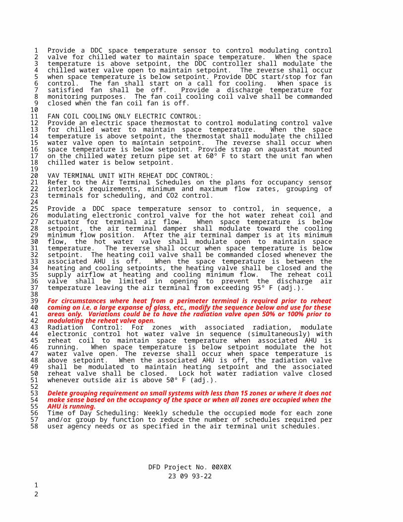
Fume hoods with variable volume airflow control shall be provided under Section 23 0916 Laboratory Temperature and Airflow Control System. All supply and general exhaust air terminals shall also be provided under Section 23 09 16 to provide a complete system for fume hood variable volume control, supply air temperature control, general exhaust control, and volume matching. All fume hood, supply, and general exhaust terminals shall have high speed actuation. Snorkels and miscellaneous exhaust terminals shall have low speed actuation. The Laboratory Temperature and Airflow Control System shall be integrated through a communication interface to the DDC control system provided under Section 23 09 23 or 23 09 24.
SWITCHED SNORKEL AND MISCELLANEOUS EXHAUST TERMINALS:If snorkel or other miscellaneous lab exhaust can be used to provide for the minimum unoccupied air change rate, do not switch the air terminal off. If it is determined that switching of the exhaust can lower the air change rates in the room for energy savings, verify with the lab planner and users that it is appropriate and safe for the exhaust to be switched off. If the terminal is to be switched off, provide for a butterfly type exhaust terminal. If the terminal is not to be switched off use a fixed venturi air valve. The primary purpose of the light is to provide indication that the terminal has been left on and not necessarily for safety, although it will give indication the exhaust is working.
Provide a toggle switch that shall be connected to the exhaust terminal DDC controller for switching off the exhaust air. Provide a green LED light located at the switch that shall be turned on by the DDC controller when the exhaust airflow exceeds 85% of the design airflow listed on the Air Terminal Schedule and shall turn off when the exhaust airflow falls below 65% of the design airflow. See Air Terminal Schedule for which air terminals are switched.
TERMINAL UNIT FAILURE MODE CONTROL:The laboratory system should be analysed to determine what the terminal units should be indexed to for flow on failure of the different elements of the supply and exhaust systems when design flow cannot be met. The control sequence for this can vary widely from facility to facility and the uses within the facility. The sequence below is based on intent and expected to be modified by the designer. Discuss options with DFD prior to final design.
The terminal units serving the building shall be indexed to their failure mode in the event of a loss of the supply or exhaust air system when more than the redundant elements of the either the supply or exhaust system has failed (the system cannot provide design airflow). The air terminals shall be indexed to and maintain the fixed airflows as scheduled on the Air Terminal Schedules. Variable volume fume hood lab systems shall operate at designed air flows, but should have their sashes shut by the users if the fume hood alarms sound.
TERMINAL UNIT SAFE EGRESS MODE CONTROL:Modify this sequence for the systems and facility to meet the intent of the sequence. Scheduling of the exhaust terminals to remain in control may be needed.
Upon complete failure of the supply fan system for a given lab system, the associated terminals shall be indexed to a Safe Egress mode. When indexed to the Safe Egress mode, all exhaust terminals with the exception of the fume hood air terminals and other specified critical exhaust shall be closed and the exhaust fans system shall be commanded to a fixed speed that provides for the maximum exhaust airflow without exceeding 0.25” w.c. pressure across any of the exterior egress doorways. The supply air terminals shall remain under control without airflow. This sequence is designed to provide maximum exhaust for safety devices connected to the fume exhaust system while still meeting the code required maximum door opening force for egress.
The following individual numbered sequences have been provided to cover a variety of different terminal unit arrangements within a lab space. The designer should modify and create additional sequences as necessary.LAB TERMINAL CONTROL SEQUENCE 1 – VARIABLE VOLUME SUPPLY AND GENERAL EXHAUST
DFD Project No. 00X0X23 09 93-22
123456789
101112131415161718192021222324252627282930313233343536373839404142434445464748495051525354555657
12
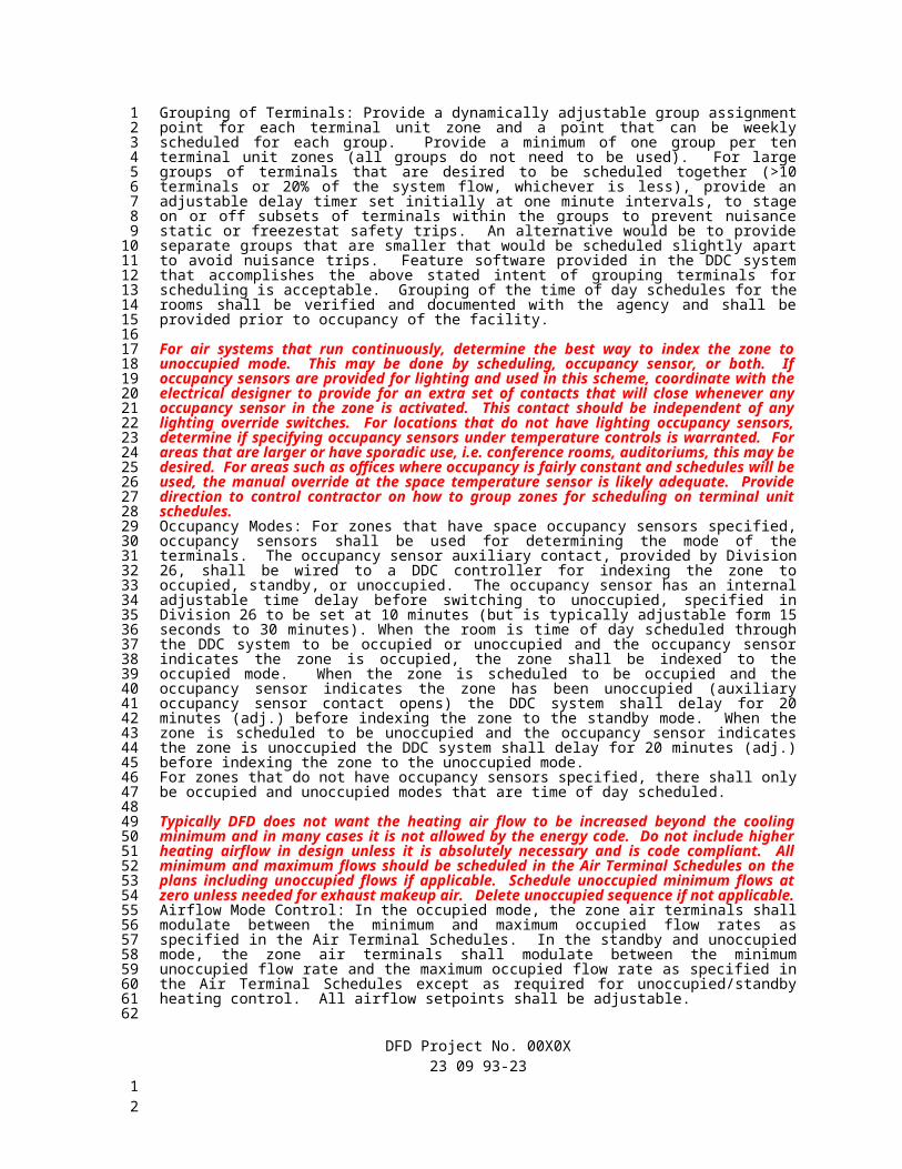
Provide a DDC space temperature sensor to control, in sequence, a modulating electronic control valve for the hot water reheat coil and actuator for supply terminal air flow. When space temperature is below setpoint, the air terminal damper shall modulate toward the cooling minimum flow position. After the air terminal damper is at its minimum flow, the hot water valve shall modulate open to maintain space temperature. The reverse shall occur when space temperature is below setpoint. The heating coil valve shall be commanded closed whenever the associated AHU is off. The reheat coil valve shall be limited in opening to prevent the discharge air temperature leaving the air terminal from exceeding 95º F (adj.).
Where radiation is provided within the lab zone, modulate the electronic control hot water valve in sequence (simultaneously) with the reheat coil valve to maintain space temperature when associated AHU is running. When space temperature is below setpoint modulate the hot water valve open. The reverse shall occur when space temperature is above setpoint. When the associated supply air system is off, the radiation valve shall be modulated to maintain heating setpoint and the associated reheat valve shall be closed. Lock hot water valve closed whenever outside air is above 50º F (adj.).
Minimum and maximum terminal unit airflows and temperature setpoints shall be set by mode as described in the General, Terminal Unit Failure, and Safe Egress sequences.
The general exhaust air terminal airflow setpoint shall be calculated by adding the measured supply airflow to the scheduled airflow offset CFM (adj.) and minus other lab exhaust (i.e. snorkels, chemical cabinet, etc.) flow values (measured or fixed value for non-measured terminals). The general exhaust air terminal shall be controlled to maintain this calculated general exhaust airflow setpoint down to the scheduled minimum airflow.
LAB TERMINAL CONTROL SEQUENCE 2 – VARIABLE VOLUME SUPPLY AND GENERAL EXHAUST with CONSTANT VOLUME FUME HOODSProvide a DDC space temperature sensor to control, in sequence, a modulating electronic control valve for the hot water reheat coil and actuator for supply terminal air flow. When space temperature is below setpoint, the air terminal damper shall modulate toward the cooling minimum flow position. After the air terminal damper is at its minimum flow, the hot water valve shall modulate open to maintain space temperature. The reverse shall occur when space temperature is below setpoint. The heating coil valve shall be commanded closed whenever the associated AHU is off. The reheat coil valve shall be limited in opening to prevent the discharge air temperature leaving the air terminal from exceeding 95º F (adj.).
Where radiation is provided within the lab zone, modulate the electronic control hot water valve in sequence (simultaneously) with the reheat coil valve to maintain space temperature when associated AHU is running. When space temperature is below setpoint modulate the hot water valve open. The reverse shall occur when space temperature is above setpoint. When the associated supply air system is off, the radiation valve shall be modulated to maintain heating setpoint and the associated reheat valve shall be closed. Lock hot water valve closed whenever outside air is above 50º F (adj.).
Minimum and maximum terminal unit airflows and temperature setpoints shall be set by mode as described in the General, Terminal Unit Failure, and Safe Egress sequences.
The general exhaust air terminal airflow setpoint shall be calculated by adding the measured supply airflow to the scheduled airflow offset CFM (adj.) minus the fume hood and other lab exhaust (i.e. snorkels, chemical cabinet, etc.) flow values (measured or fixed value for non-measured terminals). The general exhaust air terminal shall be controlled to maintain this calculated general exhaust airflow setpoint.
LAB TERMINAL CONTROL SEQUENCE 3 – VARIABLE VOLUME SUPPLY AND GENERAL EXHAUST with CONSTANT VOLUME and/or TWO POSITION VOLUME FUME HOODSProvide a DDC space temperature sensor to control, in sequence, a modulating electronic control valve for the hot water reheat coil and actuator for supply terminal air flow. When space temperature is below setpoint, the air terminal damper shall modulate toward the cooling minimum flow position. After the air terminal damper is at its minimum flow, the hot water valve shall modulate open to maintain space temperature. The reverse shall occur when space temperature is below setpoint. The heating coil valve shall be commanded closed whenever the associated AHU is off. The reheat coil valve shall be limited in opening to prevent the discharge air temperature leaving the air terminal from exceeding 95º F (adj.).
DFD Project No. 00X0X23 09 93-23
123456789
1011121314151617181920212223242526272829303132333435363738394041424344454647484950515253545556575859
12
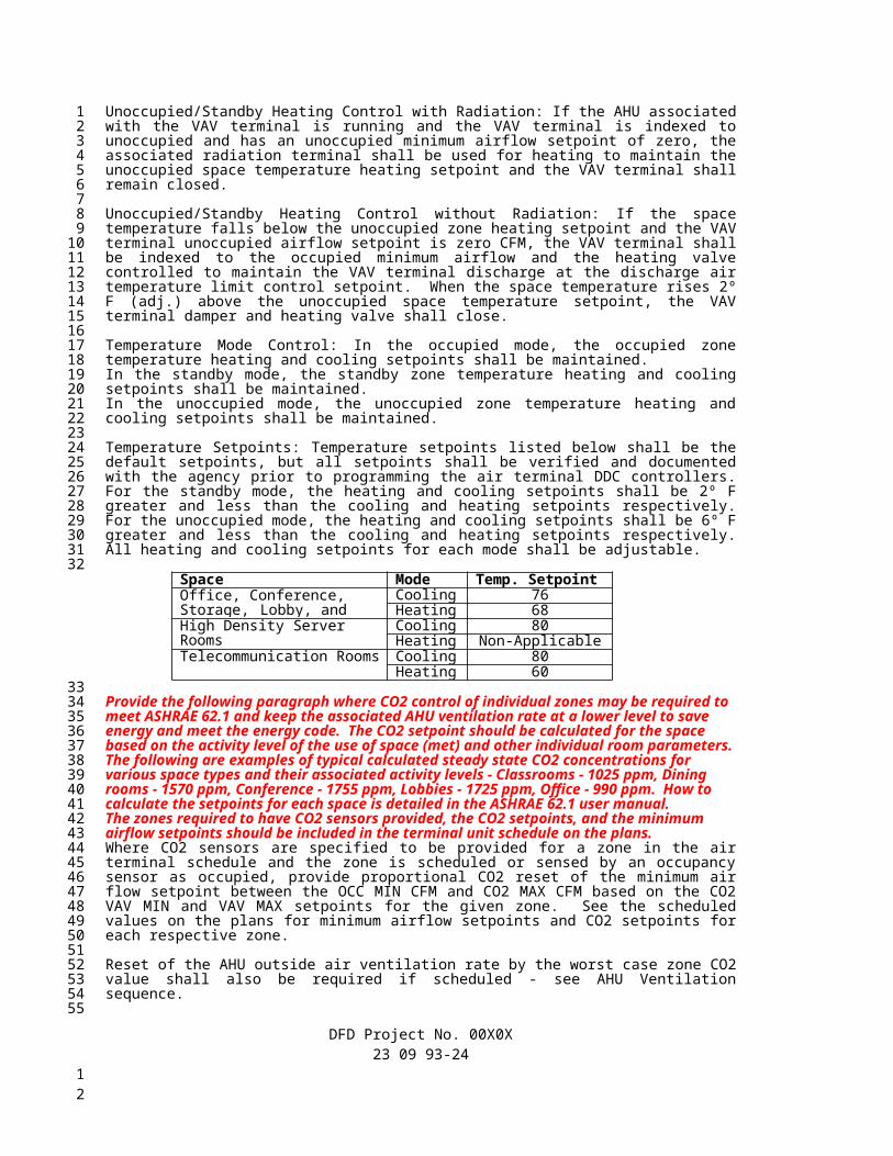
Where radiation is provided within the lab zone, modulate the electronic control hot water valve in sequence (simultaneously) with the reheat coil valve to maintain space temperature when associated AHU is running. When space temperature is below setpoint modulate the hot water valve open. The reverse shall occur when space temperature is above setpoint. When the associated supply air system is off, the radiation valve shall be modulated to maintain heating setpoint and the associated reheat valve shall be closed. Lock hot water valve closed whenever outside air is above 50º F (adj.).
Minimum and maximum terminal unit airflows and temperature setpoints shall be set by mode as described in the General, Terminal Unit Failure, and Safe Egress sequences.
The general exhaust air terminal airflow setpoint shall be calculated by adding the measured total supply airflow to the scheduled airflow offset CFM (adj.) minus the measured total fume hood and other lab exhaust (i.e. snorkels, chemical cabinet, etc.) flow values. The general exhaust air terminal shall be controlled to maintain this calculated general exhaust airflow setpoint.
The supply air terminal airflow shall be increased to a volume matching setpoint that shall be greater than the temperature control airflow setpoint to maintain the scheduled zone airflow offset when the general exhaust air terminal is at its scheduled minimum airflow value and the total zone exhaust flow exceeds the supply flow plus the airflow offset.
The fume hoods shall be controlled per Constant Volume Fume Hood Control or Two-Position Fume Hood Control sequences as defined in the Air Terminal Unit schedules.
LAB TERMINAL CONTROL SEQUENCE 4 – VARIABLE VOLUME SUPPLY AND EXHAUST with CONSTANT VOLUME and/or TWO POSITION VOLUME FUME HOODS with FUME HOOD SWITCHING FOR TEMPERATURE CONTROLProvide a DDC space temperature sensor to control, in sequence, a modulating electronic control valve for the hot water reheat coil and actuator for supply terminal air flow. When space temperature is below setpoint, the air terminal damper shall modulate toward the cooling minimum flow position. After the air terminal damper is at its minimum flow, the hot water valve shall modulate open to maintain space temperature. The reverse shall occur when space temperature is below setpoint. The heating coil valve shall be commanded closed whenever the associated AHU is off. The reheat coil valve shall be limited in opening to prevent the discharge air temperature leaving the air terminal from exceeding 95º F (adj.).
Where radiation is provided within the lab zone, modulate the electronic control hot water valve in sequence (simultaneously) with the reheat coil valve to maintain space temperature when associated AHU is running. When space temperature is below setpoint modulate the hot water valve open. The reverse shall occur when space temperature is above setpoint. When the associated supply air system is off, the radiation valve shall be modulated to maintain heating setpoint and the associated reheat valve shall be closed. Lock hot water valve closed whenever outside air is above 50º F (adj.).
Fume Hood Switching for Temperature Control: The two-position fume hoods airflow shall be switched to the active state when additional supply air is required for cooling and either the general exhaust terminal is at maximum flow or there is not a general exhaust air terminal for the zone. The additional supply air is provided by maintaining the scheduled airflow offset. For zones with multiple fume hoods, the fume hoods shall be staged on in sequence to provide more supply air for cooling. Only the number of fume hoods that are required to provide for the scheduled maximum airflow shall be switched on for temperature control. The sequences above for switching the fume hoods into and out of the active mode shall be followed.
Minimum and maximum terminal unit airflows and temperature setpoints shall be set by mode as described in the General, Terminal Unit Failure, and Safe Egress sequences.
The general exhaust air terminal airflow setpoint shall be calculated by adding the measured total supply airflow to the scheduled airflow offset CFM (adj.) minus the measured total fume hood and other lab exhaust (i.e. snorkels, chemical cabinet, etc.) flow values. The general exhaust air terminal shall be controlled to maintain this calculated general exhaust airflow setpoint.
The supply air terminal airflow shall be increased to a volume matching setpoint that shall be greater than the temperature control airflow setpoint to maintain the scheduled zone airflow offset when the general exhaust air terminal is at its scheduled minimum airflow value and the total zone exhaust flow exceeds the supply flow plus the airflow offset.
DFD Project No. 00X0X23 09 93-24
123456789
1011121314151617181920212223242526272829303132333435363738394041424344454647484950515253545556575859606162
12

The fume hoods shall be controlled per Constant Volume Fume Hood Control or Two-Position Fume Hood Control sequences specified above as defined in the Air Terminal Unit schedules.
LAB TERMINAL CONTROL SEQUENCE 5 – VARIABLE VOLUME SUPPLY AND GENERAL EXHAUST with VARIABLE VOLUME FUME HOODSThe following sequence shall be accomplished by the Section 23 09 16 Laboratory Temperature and Airflow Control System.
Provide a DDC space temperature sensor to control, in sequence, a modulating electronic control valve for the hot water reheat coil and actuator for supply terminal air flow. When space temperature is below setpoint, the air terminal damper shall modulate toward the cooling minimum flow position. After the air terminal damper is at its minimum flow, the hot water valve shall modulate open to maintain space temperature. The reverse shall occur when space temperature is below setpoint. The heating coil valve shall be commanded closed whenever the associated AHU is off. The reheat coil valve shall be limited in opening to prevent the discharge air temperature leaving the air terminal from exceeding 95º F (adj.).
Where radiation is provided within the lab zone, modulate the electronic control hot water valve in sequence (simultaneously) with the reheat coil valve to maintain space temperature when associated AHU is running. When space temperature is below setpoint modulate the hot water valve open. The reverse shall occur when space temperature is above setpoint. When the associated supply air system is off, the radiation valve shall be modulated to maintain heating setpoint and the associated reheat valve shall be closed. Lock hot water valve closed whenever outside air is above 50º F (adj.).
Minimum and maximum terminal unit airflows and temperature setpoints shall be set by mode as described in the General, Terminal Unit Failure, and Safe Egress sequences.
The general exhaust air terminal airflow setpoint shall be calculated by adding the measured total supply airflow to the scheduled airflow offset CFM (adj.) minus the measured total fume hood and other lab exhaust (i.e. snorkels, chemical cabinet, etc.) flow values. The general exhaust air terminal shall be controlled to maintain this calculated general exhaust airflow setpoint.
The supply air terminal airflow shall be increased to a calculated volume matching setpoint that shall be greater than the temperature control airflow setpoint to maintain the scheduled zone airflow offset when the general exhaust air terminal is at its scheduled minimum airflow value and the total zone exhaust flow exceeds the supply flow plus the scheduled airflow offset.
The fume hoods shall be controlled to maintain a constant face velocity as the sash is raised and lowered until the air terminal unit reaches its minimum flow setpoint.
LAB TERMINAL CONTROL SEQUENCE 6 – CONSTANT VOLUME SUPPLY AND GENERAL EXHAUSTThe following sequence is for negatively pressurized labs. If the lab requires positive pressure, reverse the supply and exhaust terminals in the sequence. If the lab has a large amount of exhaust air and over-pressurization of the space is determined to be a problem, additional controls may be required to prevent damage to the space.
Provide a DDC space temperature sensor to control, in sequence, a modulating electronic control valve for the hot water reheat coil and actuator for supply terminal air flow. When space temperature is below setpoint, the hot water valve shall modulate open to maintain space temperature. The reverse shall occur when space temperature is below setpoint. The heating coil valve shall be commanded closed whenever the associated AHU is off. The reheat coil valve shall be limited in opening to prevent the discharge air temperature leaving the air terminal from exceeding 95º F (adj.).
Where radiation is provided within the lab zone, modulate the electronic control hot water valve in sequence (simultaneously) with the reheat coil valve to maintain space temperature when associated AHU is running. When space temperature is below setpoint modulate the hot water valve open. The reverse shall occur when space temperature is above setpoint. When the associated supply air system is off, the radiation valve shall be modulated to maintain heating setpoint and the associated reheat valve shall be closed. Lock hot water valve closed whenever outside air is above 50º F (adj.).
The terminal unit airflows and temperature setpoints shall be set by mode as described in the General, Terminal Unit Failure, and Safe Egress sequences.
DFD Project No. 00X0X23 09 93-25
123456789
101112131415161718192021222324252627282930313233343536373839404142434445464748495051525354555657585960616263
12
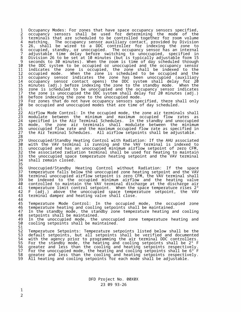
Under the normal mode, the general exhaust air terminals shall be controlled to a fixed airflow setpoint as specified in the Air Terminal Schedule.
The supply air terminal airflow setpoint shall be calculated by adding the measured general airflow to the scheduled airflow offset CFM (adj.) and plus other lab exhaust (i.e. snorkels, chemical cabinet, etc.) flow values (measured or fixed value for non-measured terminals). The general exhaust air terminal shall be controlled to maintain this calculated general exhaust airflow setpoint. This is sequence is designed to maintain a negative pressure in the lab on exhaust air flow loss.
LAB TERMINAL CONTROL SEQUENCE 7 – VARIABLE VOLUME SUPPLY AND RETURN AIR TERMINALSProvide a DDC space temperature sensor to control, in sequence, a modulating electronic control valve for the hot water reheat coil and actuator for supply terminal air flow. When space temperature is below setpoint, the air terminal damper shall modulate toward the cooling minimum flow position. After the air terminal damper is at its minimum flow, the hot water valve shall modulate open to maintain space temperature. The reverse shall occur when space temperature is below setpoint. The heating coil valve shall be commanded closed whenever the associated AHU is off. The reheat coil valve shall be limited in opening to prevent the discharge air temperature leaving the air terminal from exceeding 95º F (adj.).
Minimum and maximum terminal unit airflows and temperature setpoints shall be set by mode as described in the General, Terminal Unit Failure, and Safe Egress sequences.
The return air terminal airflow setpoint shall match the measured supply airflow. The return air terminal shall be controlled to maintain this calculated return airflow setpoint down to the scheduled minimum airflow.
LAB TERMINAL CONTROL SEQUENCE 8 – VARIABLE VOLUME SUPPLY AND RETURN AIR TERMINALS – COOLING ONLYProvide a DDC space temperature sensor to control the actuator for supply terminal air flow. When space temperature is below setpoint, the air terminal damper shall modulate toward the cooling minimum flow position. The reverse shall occur when space temperature is below setpoint.
Minimum and maximum terminal unit airflows and temperature setpoints shall be set by mode as described in the General, Terminal Unit Failure, and Safe Egress sequences.
The return air terminal airflow setpoint shall match the measured supply airflow. The return air terminal shall be controlled to maintain this calculated return airflow setpoint down to the scheduled minimum airflow.
PRIMARY HUMDIFIER CONTROL:Adjust humidity setpoints based on program needs for the space and the ability of the structure to withstand the internal humidity load. When retrofitting buildings for humidification, research should be done by the design team to ensure that the building envelope will be able to contain the moist air without damage or other adverse effects. Revise the discharge humidity control range setpoints as required by psychrometrics to maintain the space humidity if the space humidity reset setpoints are revised from the high and low setpoints listed below.
It is critically important to locate the high limit sensors at a proper distance downstream of the humidifier especially on systems that may have VAV control. Failure to do this will result in cycling of the humidifier, failure of humidity sensors, and overall poor control.
Edit the specification below to eliminate the condensate temperature switch and two-position line sized control valve if short absorption humidifier dispersion tubes are used. Special care in how the condensate lines from these humidifiers are designed is required to prevent any back pressure to the humidifier. This back pressure can result in condensate spilling out into the ductwork. Oversizing condensate return lines is recommended for long runs.
DFD Project No. 00X0X23 09 93-26
123456789
101112131415161718192021222324252627282930313233343536373839404142434445464748495051525354555657
12

Control primary humidifiers located in the air handling units by discharge air humidity sensors to maintain a humidity setpoint that is reset from [space] [return] [exhaust] humidity sensors as shown on the plans or specified under Section 23 09 15. The discharge air humidity setpoint shall be reset between 20% RH (adj.) and 85% RH (adj.) to maintain the PI loop calculated reset [space] [return] [exhaust] humidity setpoint. Provide two electronic discharge air humidity sensors for discharge humidity control. The highest humidity reading of the two discharge humidity sensors shall maintain the calculated discharge humidity setpoint. If the humidity readings of the two sensors vary by more than 8% RH (adj.), an alarm shall be sent through the DDC system. The [space] [return] [exhaust] humidity setpoint shall be reset between 35% RH (adj.) at an outside air dry bulb temperature of 50° F (adj.) and 20% RH (adj.) at an outside air dry bulb temperature of 0° F (adj.). Mount the humidity sensors at the same location a minimum of 6 feet or greater if required by humidifier manufacturer and a maximum distance of 15 feet. Whenever possible, humidity sensors should be located on the same side of the ductwork that the steam feed to humidifier is located. The humidifier control loop shall not be active until the supply fan speed signal exceeds 20% (adj.) command.
The 23 09 14 contractor shall be responsible for connecting the temperature switch provided with the humidifier and located in the humidifier condensate line to prevent the humidifier operation by overriding the control signal to the humidifier control valve until condensate has reached a temperature of approximately 205º F, not adjustable.
Provide a two-position line sized control valve located in the steam line feeding the humidifier if the humidifier is provided with a jacketed manifold. This valve and the humidifier control valve shall be closed whenever outside air temperature is above 50º F, when the cooling coil valve is open, or whenever the associated air handling unit is off or operating below a fan speed of 20% (adj.).
Add the following if serving sensitive areas where damage may result from humidifier malfunction and extra protection is deemed necessary. Provide a duct mounted moisture detector that shall close the humidifier valve through a hardwire or pneumatic interlock independent of the DDC control when moisture is detected in the bottom of the ductwork. A DDC alarm shall be generated when this occurs.
Add the following paragraph if multiple air handling units are ducted in parallel.All primary humidifiers serving the same air system shall be controlled from a single control loop output to prevent the humidifiers from getting out of synch with each other. Shutdown of any of the air handling units shall disable their associated humidifier but shall not impact the operation of the other unit’s operating humidifiers.
BOOSTER HUMDIFIER CONTROL:For rooms that have booster humidifiers and are under negative pressure, location of the humidity sensor needs to be carefully determined to prevent false readings due to air being drawn into the room from adjacent areas. Locate the sensor away from the door in rooms designed to be under negative pressure to adjacent spaces. Additionally, special care needs to be taken to ensure good ventilation effectiveness to prevent short circuiting of humidification from supply to return/exhaust. This is especially important if return/exhaust humidity sensing is used to control the booster humidifier. Return or exhaust should be pulled from the floor if possible otherwise wall mounted humidity sensors will measure lower humidity than will be present in the middle of the room. Where booster humidifiers are used with associated VAV terminals, ensure that the minimum scheduled airflow is higher than the minimum rating of air flow for the booster humidifier.
Edit the specification below to eliminate the condensate temperature switch and two-position line sized control valve if short absorption humidifier dispersion tubes are used
Control booster humidifiers located in the ductwork by [space, return, exhaust] air humidity sensor to maintain a constant humidity setpoint. The setpoint shall be [insert setpoint]% RH (adj.). Provide an electronic discharge air humidity sensor that shall limit the discharge humidity to 90% RH (adj.). Mount the humidity discharge sensor a minimum of 6 feet or greater if required by humidifier manufacturer. Where booster humidifiers have associated VAV terminals, the humidifier control valve shall be closed whenever the VAV terminal air flow is below the manufacturers rated minimum airflow for the booster humidifier.
DFD Project No. 00X0X23 09 93-27
123456789
101112131415161718192021222324252627282930313233343536373839404142434445464748495051525354555657585960
12

The 23 09 14 contractor shall be responsible for connecting the temperature switch provided with the humidifier and located in the humidifier condensate line to prevent the humidifier operation by overriding the control signal to the humidifier control valve until condensate has reached a temperature of approximately 205º F, not adjustable.
Provide a two-position line sized control valve located in the steam line feeding the humidifier if the humidifier is provided with a jacketed manifold. This valve and the humidifier control valve shall be closed whenever outside air temperature is above 50º F, when the cooling coil valve is open, or whenever the associated air handling unit is off. Add the following if serving sensitive areas where damage may result from humidifier malfunction and extra protection is deemed necessary. Provide a duct mounted moisture detector that shall close the humidifier valve through a hardwire or pneumatic interlock independent of the DDC control when moisture is detected in the bottom of the ductwork. A DDC alarm shall be generated when this occurs.
HEAT WHEEL CONTROL:This is a generic sequence for enthalpic heat wheels that are to be controlled by the DDC contractor and not part of a packaged control system. For most AHU systems that have a heat wheel included in their design, this sequence should be used and incorporated into the AHU specification. Frost control utilizing wheel speed is the simplest and most economical with low exhaust humidity applications (<30% RH). The amount of bin hours where frosting will occur is minimal and for most low humidity applications, not worth the first cost and fan penalty of increased pressure drop of a preheat coil. For spaces that have higher humidity requirements and frosting will occur at higher outside air temperatures, using a preheat coil in either the outside or exhaust air streams should be considered due to increased enthalpy recovery and energy savings.
Heat Wheel Heating Discharge Air Temperature Control: The heat wheel shall be used as the first stage of heating and shall be sequenced with the preheat coil, mixed air dampers, and cooling coil to maintain the discharge temperature setpoint. The VFD speed shall be modulated to maintain the discharge air temperature setpoint subject to the frost control override. The heat wheel shall be indexed off above 50º F (adj.).
Heat Wheel Cooling Discharge Air Temperature Switchover Control: The heat wheel shall be indexed to full speed whenever the return/exhaust air temperature is 5 º F (adj.) less than the outside air temperature.
Bypass Damper Control: Open the bypass dampers whenever the heat wheel is indexed off.
Frost Control: Override the heating wheel speed control to limit the leaving exhaust air temperature from the wheel to 15º F (adj.) at a relative exhaust air entering humidity of 30% RH (adj.) and reset linearly to 5º F (adj.) at 20% RH.
Cold Weather Start: Whenever outside air temperature is below 40º F (adj.), start the wheel at full speed and run the unit in full recirculation mode or run the exhaust fan for 3 minutes to pre-warm the wheel before starting the supply fan and then release the wheel to control.
Purge Control: When the heat wheel is deactivated, the wheel shall run for 20 seconds at minimum speed every 30 minutes to keep the rotor surface clean.
Rotation Alarm: The heat wheel shall come factory equipped with a proximity switch that shall provide a dry contact input to the DDC system. If the wheel is indexed to run and two switch closures are not seen within 10 minutes, an alarm shall be sent through the DDC system signalling a wheel rotation failure.
VARIABLE VOLUME MIXED AIR HANDLING UNIT CONTROL (AHU-X):
GENERAL:Modify the AHU description below to match actual design, i.e. for 100% outside air units.The Air Handling unit is variable air volume, indoor air unit.The Air Handling unit is controlled by direct digital controller (DDC).The Air Handling unit is equipped with the following:
Supply fan with VFD.
DFD Project No. 00X0X23 09 93-28
123456789
1011121314151617181920212223242526272829303132333435363738394041424344454647484950515253545556575859606162
12

Supply, Return, and outside air airflow measuring stations furnished by Temperature Control Contractor (TCC). (Refer to specification 23 09 14)
Return fan with VFD. Outside air damper furnished by TCC. (Refer to specification 23 09 14) Minimum outside air damper furnished by TCC. (Refer to specification 23 09 14) Return air damper furnished by TCC. (Refer to specification 23 09 14) Relief air damper furnished by TCC. (Refer to specification 23 09 14) Chilled water coil for cooling. VIFB steam coil for heating. (All damper actuators shall be furnished with the VIFB steam coil.) 30% and 60% filter bank. Actuators furnished by TCC. (Refer to specification 23 09 14)
FAN CONTROL:Start/Stop: The DDC system shall start the supply and return fan via the VFD. Insert the following sequence for fan systems with multiple supply fans. Edit the sequence and speed setpoints for systems with more than two supply fans or two manifolded AHU’s. This sequence can also be used for manifolded exhaust systems.For fan systems with two supply fans, sequence fans on based on supply fan speed. When fan speed is at 95% or more for 15 minutes (adj.), start the next supply fan. All supply fans shall be controlled at the same speed. When commanded fan speeds fall to 40% for 15 minutes (adj.), shut off the lag supply fan. When starting a fan, command the fan to start and run at minimum speed. When fan status is proven on, command the isolation damper open and release the fan to control. If a fan status does not prove on or the isolation damper end switch does not prove open within 2 minutes (adj.) of the fan start or damper open commands, command the supply fan off and the isolation damper closed, latch out this supply fan, and send a supply fan failure alarm through the DDC system. Provide a manual push-button switch located in the control panel and a software point to reset the shutdown latch out of the fan. When stopping a lag fan, command the damper to close and ramp the fan down to minimum speed at the same rate as the damper actuator stroke time (typically 90 seconds). After the fan is at minimum speed and the damper end switch indicates the damper is closed, command the fan off. When switching lead fans and stopping a lag fan, prove operation of the new lead fan and allow 2 minutes (adj.) for the fan to come up to speed before initiating the stop fan sequence. Provide a software point and hardware switch located inside the control panel for each fan to be taken out of service that shall initiate the shutdown sequence for the fan. If there is a lag fan that is available, it’s start sequence shall be initiated and come into control before the shutdown sequence for the fan being taken out of service is stopped.
The above sequence may need to be modified to prevent static pressure variances as specified General, Parallel Fan Bumpless Transfer sequence. This may entail adjusting minimum speeds and/or ramping dampers or fans at different rates than specified above.
Current Status Switch: Provide as described under GENERAL, VFD Motor Run Status, in this Section for both the supply and return fans.
Delete for fan systems that do not have VFD bypass starters.Manual VFD Bypass Operation: In the event of a VFD failure and bypass operation is desired, the VAV terminals associated with the AHU shall be indexed to their maximum flow rate through the VAV terminal master command point (see DDC Controlled Terminal Unit Master Command Points). After sufficient time to allow the VAV terminals to open (approximately two minutes), the supply and return fan VFD’s shall be manually indexed to bypass.
It may be necessary to provide multiple static pressure sensing locations depending on the size and loading of the air system. Try to minimize the number of static sensing locations. Show all locations on the plans – do not leave this to the contractor. Locate static sensing location at the furthest point in the system as possible while avoiding static pressure fluctuations due to single terminal units. Multiple sensing locations are not required if the static pressure reset control strategy is employed.
DFD Project No. 00X0X23 09 93-29
123456789
101112131415161718192021222324252627282930313233343536373839404142434445464748495051525354
12

Supply Fan Speed Control: The purpose of the supply fan control is to maintain a minimum static pressure in the supply ductwork to insure proper terminal air box operation. Install a static pressure sensing probe in the main supply duct located at approximately ¾ of the way down the main supply duct as shown on the plans and pipe to the differential pressure transmitter that shall be located in the unit temperature control panel. The inputs to the differential pressure transmitter shall be the static pressure inside of the duct and the reference input shall sense the actual space served by the air system located in the ceiling below the duct probe. The DDC system shall modulate the supply fan VFD to maintain the static pressure setpoint as sensed by the static pressure sensor. If multiple supply fans are used, the same speed signal shall be sent to all operating fans unless the fan is in start or stop mode as described above. If multiple sensing locations are shown, the DDC system shall maintain the static pressure setpoint at the lowest reading sensor. If the static sensors deviate by more than 0.5 in. w.c. (adj.), an alarm shall be sent through the DDC system. Static pressure setpoint shall be as described in the Static Pressure Reset Control below.
Fan Static Pressure Setpoint Reset Control: Static pressure setpoint shall be reset using true Trim & Respond logic within the range 0.3 in w.c. (adj.) to 1.2 in w.c. (adj.). When the fan is off, the setpoint shall be reset to 1 in. w.c. (adj.) and this setpoint shall be used on system start up. While the fan is proven on, every three minutes, (adj.) trim the setpoint by 0.04 in. w.c. downward if there are zero zone pressure requests. If there are more than one zone pressure requests, respond by increasing the setpoint upward by 0.06 in. w.c. If there is exactly one zone pressure request, the static pressure setpoint shall not be adjusted.
Each zone VAV shall produce a zone pressure request analog value of 0, 1 or 2. When the VAV damper is less than 90% (adj.) open the pressure request analog value shall be zero. If the VAV damper is greater than 90% (adj.) and less than the pressure request two setpoint, then the pressure request analog value shall be one. If the VAV Damper is greater than 99% open for 60 seconds (adj.) then the zone pressure request analog value shall be two. Zone pressure requests for each VAV zone associated with the AHU shall be summed in the supervisory controller. Provide a binary data enable point for each zone to enable/disable the VAV damper in the trim and respond algorithm. All setpoints, timers, and zone pressure request threshold for the static pressure reset shall be adjustable. Tune the reset to prevent cyclic instability after the space is occupied. Provide a trend graph to show the relative stability of the static pressure setpoint. Final maximum setpoint shall be determined by the Balancing Contractor to satisfy the worst case zone at maximum design condition.When more than 10% of the air terminals are indexed to occupied and the static pressure setpoint is below the fan start static setpoint, reset the static pressure to the fan start setpoint and release to trim and respond control. This is to prevent slow system recovery on scheduled start-up.
Use the following sequence for AHU’s that have a more critical function should not shutdown unless absolutely necessary, i.e. make-up air for lab exhaust. This will allow the fan system to continue to run if the duct static sensor fails. For a normal mixed air unit serving an office or classroom space, delete this sequence.Supply System High Static Pressure Control: Install a static pressure probe located in the supply fan discharge or on a manifolded supply system, in the common supply plenum or ductwork and pipe to a differential pressure sensor located in the temperature control panel. This sensor shall override the speed signal to supply fan VFD to limit the static pressure to 3.5” w.c. (adj.) (this setpoint should be set to 0.5” w.c. less than the pressure class of the ductwork). Reference input for the differential pressure sensor shall be the temperature control panel. If this control is invoked, send an supply high pressure alarm to the DDC system.
Return Fan Speed Control: The purpose of the return fan control is to maintain a slightly positive building pressure. The return fan VFD shall modulate to maintain a constant CFM offset of [ insert setpoint] (adj.) from the supply fan to account for total exhaust from the area in which it serves while maintaining a slightly positive pressure. A.T.C. shall coordinate with the balancing contractor to optimize this setting.
Insert the following sequence for fan systems with multiple return fans. Edit the sequence and speed setpoints for systems with more than two return fans or two manifolded AHU’s.
DFD Project No. 00X0X23 09 93-30
123456789
10111213141516171819202122232425262728293031323334353637383940414243444546474849505152535455
12

For fan systems with two return fans, sequence fans on based on return fan speed. When fan speed is at 95% or more for 15 minutes (adj.), start the next return fan. All return fans shall be controlled at the same speed. When commanded fan speeds fall to 40% for 15 minutes (adj.), shut off the lag return fan. If multiple return fans are used, the same speed signal shall be sent to all operating fans unless the fan is in start or stop mode as described below. When starting a fan, command the fan to start and run at minimum speed. When fan status is proven on, command the isolation damper open and release the fan to control. If a fan status does not prove on or the isolation damper end switch does not prove open within 2 minutes (adj.) of the fan start or damper open commands, command the return fan off and the isolation damper closed, latch out this return fan, and send a return fan failure alarm through the DDC system. Provide a manual push-button switch located in the control panel and a software point to reset the shutdown latch out of the fan. When stopping a lag fan, command the damper to close and ramp the fan down to minimum speed at the same rate as the damper actuator stroke time (typically 90 seconds). After the fan is at minimum speed and the damper end switch indicates the damper is closed, command the fan off. When switching lead fans and stopping a lag fan, prove operation of the new lead fan and allow 2 minutes (adj.) for the fan to come up to speed before initiating the stop fan sequence. Provide a software point and hardware switch located inside the control panel for each fan to be taken out of service that shall initiate the shutdown sequence for the fan. If there is a lag fan that is available, it’s start sequence shall be initiated and come into control before the shutdown sequence for the fan being taken out of service is stopped.
VENTILATION AIR CONTROL:The ventilation rate for an AHU may be fixed or reset. Fixed ventilation rates would typically be used where exhaust air and building pressurization air associated with the AHU will be above the full occupancy of the space at all times. Reset of the ventilation rate will typically be used to reset between a calculated ventilation rate from zone occupancy and ASHRAE 62.1 critical zone calculated airflow required for full occupancy or 15 CFM/person (DFD ventilation design guideline), whichever is less. Occupancy sensors and CO2 control of zones can be used to reset the AHU ventilation rate. One of two methods to reset the outside air ventilation rate at the AHU can be used.
The first is to reset the amount of ventilation outside air flow based on a summed ventilation value of each zone. The greater of the base ventilation rate or the summed value will be used as the ventilation rate for the AHU. The base ventilation rate will be the make-up air required for the exhaust or the ventilation required by the zones without occupancy sensors, whichever is greater. The occupancy CFM of each room should be calculated by the design number of occupants in each zone times a ratio factor that will result in the full AHU calculated ventilation rate when all zones are occupied. The ratio factor shall be calculated by total design building occupant divided by the total design zone occupants (design building occupancy diversity). The calculated OA CFM for each zone should be inserted in the VAV terminal schedule under the OCC OA VENT CFM column.
The second method is to sum the ventilation value for each zone like the first method but the zones with CO2 sensing will only use the ASHRAE 62.1 Area Outdoor Air Rate value for the zone OCC OA VENT CFM column in the VAV schedule. The CO2 sensors will directly reset the AHU ventilation rate from the calculated summed zone ventilation rate or base ventilation rate whichever is greater, up to the maximum ASHRAE 62.1 calculated ventilation air flow based on the critical zone analysis – insert this value into the maximum outside air ventilation rate setpoint in the sequence below.
Fixed Ventilation Air Flow Setpoint: The AHU outside air ventilation rate shall be maintained at xxx CFM.
If reset of outside air ventilation rates is desired, use one of the following two sequences. Use the first sequence if occupancy sensors are used but no CO2 reset is used.
Reset Ventilation Air Flow Setpoint by Summing Zone Ventilation Rates: The outside air ventilation rate required at the AHU shall be determined the greater of the base ventilation rate setpoint of xxx CFM or the sum of the ventilation airflow required by each zone associated with the AHU. The zone ventilation values to be summed shall be based on the OCC OA Vent CFM as scheduled on the plans. Sum the value of the zones without occupancy sensors and the zones that have occupancy sensors only when they are occupied.
DFD Project No. 00X0X23 09 93-31
123456789
101112131415161718192021222324252627282930313233343536373839404142434445464748495051525354555657
12
Reset Ventilation Air Flow Setpoint by Summing Zone Ventilation Rates and Direct CO2 Control: The base outside air ventilation rate required at the AHU shall be determined by the greater of the base ventilation rate setpoint of xxx CFM or the sum of the ventilation airflow required by each zone associated with the AHU. The zone ventilation values to be summed shall be based on the OCC OA Vent CFM as scheduled on the plans. Sum the value of the zones without occupancy sensors and the zones that have occupancy sensors only when they are occupied. The worst-case zone CO2 sensor reset value shall directly reset the outside air ventilation rate from the base ventilation rate to the maximum outside air ventilation rate setpoint of [xxx] CFM based on the CO2 AHU MIN (PPM) and AHU MAX (PPM) setpoint values as scheduled on the plans.
Use the following paragraph if indexing of occupancy is desired. Edit as required for number of occupancy indexes and method of indexing to the different rates. The code required minimum will be 7.5 CFM/Person has to be maintained so this sequence would be used for a space that would have highly variable occupancy such as a gymnasium where the base ventilation rate can be greatly reduced. Provide a [software or hardware or both] occupancy switch to index the system to the desired occupancy ventilation rate for the space served per the following schedule. If a hardware switch is provided, locate where shown on plans.
Maximum Occupancy: [xxx CFM]Intermediate Occupancy: [xxx CFM]Minimum Occupancy: [xxx CFM]
There are three methods of minimum outside air ventilation control that can be used:1. The first is to simply use volume matching between the supply and return fan. This should only be used whenever the air handling unit is fairly small and the ventilation rate is equal to the volume matching setpoint (the ventilation rate is exhaust driven) or when the unit is at full design turndown and the mixed air temperature will be 55º F or higher at design outdoor air temperature conditions at design required ventilation airflow (unlikely).
2. Use a minimum outside duct and airflow station and directly measure the amount of outside air. Proper amount of straight ductwork and/or the use of thermal dispersion airflow stations need to be considered in this design.
3. Use an airflow station in the outside air duct that will measure all entering outside air (no minimum outside air duct). This should only be used where the minimum ventilation airflow rate can be kept above a duct velocity of approximately 150 FPM so accuracy is maintained. This is a preferred method as it is a simpler control scheme.
Minimum Ventilation Air Flow Control Using Volume Matching: The minimum outside air damper position shall be reset between a high minimum position and a low minimum position reset from the full design turndown fan speed and maximum fan speed. The Temperature Control Contractor shall work with the Balancing Contractor to determine these damper position setpoints to provide a relatively even mixed air static pressure over the full range of fan turndown.
Minimum Ventilation Air Flow Control Using a Full Flow Outside Air Flow Station: When the economizer sequence is not enabled, the outside air damper shall modulate open to maintain the outside air flow minimum ventilation rate setpoint. When the outside air damper is 100% open, the return damper shall modulate towards closed to maintain the outside air flow minimum ventilation rate setpoint. When the economizer sequence is enabled, the outside air and return air dampers shall be limited from controlling below the outside air ventilation flow rate.
Minimum Ventilation Air Flow Control Using a Minimum Outside Air Flow Station: The minimum outside air damper shall modulate to maintain the minimum outside airflow ventilation setpoint. When the minimum outside air damper is fully open and the ventilation airflow rate is below setpoint, the return damper shall be overridden to modulate closed to maintain the minimum ventilation airflow rate. The return damper shall be limited to being overridden to 50% closed (adj.) in this mode. The Temperature Control Contractor shall work with the Balancing Contractor to determine the return damper limit setpoint required to provide the maximum ventilation airflow rate when the air handling unit is at full turndown. When the economizer outside air damper is modulated open to maintain the discharge air temperature, the return shall modulate as described in the discharge air temperature control sequence and shall not be overridden to maintain minimum ventilation. Final setpoints shall be included in the as-built sequence of operation by the Temperature Control Contractor.
DFD Project No. 00X0X23 09 93-32
123456789
101112131415161718192021222324252627282930313233343536373839404142434445464748495051525354555657585960616263
12

Use the following paragraph only for outside air ventilation rates that exceed the exhaust rates from exhaust fans for the space served for the preceding strategy that also uses minimum outside air duct flow measurement. The problem that will occur without a low temperature switchover to re-enable the outside air ventilation flow control will be that the return air will be re-entrained by the supply fan to maintain the economizer temperature control rather than be forced out of the relief damper. Because the volume matching differential between supply and return fans will be less than the outside air ventilation required and because the relief, return, and economizer dampers are modulated together, the return air will not be forced out of the relief damper. This will result in maintaining economizer temperature control but the outside air ventilation flow rate will be reduced below the level required. Without this sequence the outside air ventilation control will not be enabled until the economizer damper is fully closed when the outside air temperature causes the economizer temperature control to be below setpoint. The economizer control must be switched off and the outside air ventilation control switched on below the outside air temperature at which the outside air flow quantity that would be required to maintain the economizer (discharge) air temperature setpoint is less than the required outside air ventilation flow rate. To do this, the outside air temperature at which this will occur must be calculated by determining the percentage of outside air required at the air handling unit’s current supply air flow. Once this is determined, the return air temperature can be used along with the outside air ventilation percentage to calculate the outside air temperature at which the economizer control should be terminated and the minimum ventilation control should be restarted. When switching in or out of economizer based on this sequence, the return air damper shall be slowly ramped to the minimum ventilation control signal position or the discharge air control signal position to allow time for relief air damper control to adjust. Use the following formulas to determine the outside air economizer low temperature switchover setpoint:%OA=Outside Air Ventilation Air Flow Setpoint/Supply Air FlowOutside Air Switchover Setpoint= (Discharge Air Setpoint/%OA)-(Return Air Temp/%OA) + Return Air TempProvide bias setpoint of 3º F (adj.) below the calculated setpoint to prevent cycling of this control sequence and compensate for heat gain due to fan and humidifier. Differential setpoint shall be 2º F (adj.).
FILTERS:Install a differential static pressure sensor across each filter bank. Ensure that the static probes do not impede filter removal.
For pre-filter bank, provide an alarm to the operator interface when the differential static pressure exceeds [enter design dirty filter drop at full flow" W.C]. (adj.).
For final filter bank, provide an alarm to the operator interface when the differential static pressure exceeds [enter design dirty filter drop at full flow" W.C]. (adj.).
DISCHARGE AIR TEMPERATURE CONTROL:Install a temperature sensor in the supply duct downstream of the supply fan, all water coils and humidifiers. Discharge Air Temperature Setpoint: Discharge air temperature setpoint shall be 55º F (adj.).
Discharge Air Temperature Control: The heating coil, mixed air dampers, and the cooling coil shall be controlled in sequence to maintain the discharge air setpoint temperature. At no time shall the heating coil be operating when the mixed air dampers are economizing or the chilled water coil valve is open. Whenever the discharge air temperature is above the setpoint, the following shall occur in sequence: The heating coil control shall modulate closed as sequenced below. When heating is completely off and the economizer sequence is enabled, the economizer outside air damper and return air damper shall be modulated sequentially (outside air damper modulates open fully before return air damper modulates towards closed) to maintain the discharge air temperature setpoint. Provide an adjustable offset setpoint for adjusting the outside and return air damper sequential control as described above. When the offset setpoint is set at 100%, the outside air damper shall be fully open before the return air damper can modulate closed. When the offset setpoint is set at 50%, the outside air damper shall be 50% open before the return air damper can modulate closed. When the offset setpoint is set at 0%, the outside air damper shall be modulated together in a complimentary fashion. Any percentage of offset is allowable. Normal offset setpoint shall be 100%. When the outside air economizer damper is completely open and the return air damper is completely closed, or the economizer sequence is not enabled, the chilled water valve shall modulate open to maintain the discharge air temperature setpoint. When the discharge air setpoint is below setpoint the reverse shall occur. Cooling coil control shall be locked out below 50º F (adj.) outside air temperature.Choose one of the following four heating coil control strategies:
DFD Project No. 00X0X23 09 93-33
123456789
1011121314151617181920212223242526272829303132333435363738404142434445464748495051525354555657585960616263
12
Integral Face and Bypass Heating Coil Control: Install a heating coil discharge temperature sensor as far downstream of the heating coil as possible while still being upstream of the chilled water coil. The heating coil shall be controlled to maintain a heating coil discharge air temperature setpoint of 53º F (adj.). Heating control shall be locked out whenever outside air temperature is above 50º F (adj.). When mixed air temperature is above 40º F (adj.), the heating coil control valve and face and bypass dampers shall be modulated together to maintain the discharge air temperature setpoint. The heating control valve shall be sequenced so that it is 25% open (adj. BAS Setpoint) before the face and bypass dampers begins to modulate. Whenever the mixed air temperature is below 40º F (adj.) or the outside air temperature is below 0º F (adj.), the heating coil control valve(s) shall be fully open and the face and bypass dampers shall modulate to maintain the discharge air temperature setpoint.
Ensure that the bypass duct is shown in an AHU section ducted downstream of the cooling coil.External Face and Bypass Heating Coil Control: Heating control shall be locked out whenever outside air temperature is above 50º F (adj.). When mixed air temperature is above 40º F (adj.), the heating coil control valve and face and bypass dampers shall be modulated together to maintain heating coil discharge air temperature. The heating control valve shall be sequenced so that it is ¼ open before the face and bypass dampers begins to modulate. Whenever the mixed air temperature is below 40º F (adj.), the heating coil control valve(s) shall be fully open and the face and bypass dampers shall modulate to maintain the discharge air temperature setpoint.
Hot Water or Steam Heating Coil Control: Modulate the heating coil control valve as sequenced under discharge air control.
Pumped Hot Water Heating Coil Control: Modulate the hot water control valve as sequenced under discharge air control. Start hot water pump whenever mixed air temperature is below 45º F (adj.). Stop hot water pump whenever mixed air temperature is above 45º F (adj.).
Use the following strategy for high percentage ventilation air units and 100% outside air units to prevent freezestat trips on cold weather start-ups. Cold Weather Start-up: On AHU start up when the outside air temperature is below 20º F (adj.), add 25º F (adj.) to the discharge temperature setpoint and ramp the discharge temperature setpoint down by 5º F (adj.) every two minutes (adj.). When the ramped down discharge temperature setpoint is within ramp down increment, release setpoint back to the normal discharge temperature setpoint. This sequence should be initiated after the heating optimal start routine below has terminated and the AHU is indexed to the occupied mode.
For units with reclaim coils upstream of the preheat coil, open the reclaim coil valve to provide full flow through the coil allowing time for the valve to provide full flow through the reclaim coil before starting the AHU. Release reclaim coil to control when supply fan status is proven.
RELIEF DAMPER CONTROL:The relief damper shall be modulated to maintain a relief plenum pressure setpoint of 0.10” w.c. (adj.). When the relief plenum pressure is abvoe setpoint, the relief damper shall modulate open. When the relief plenum pressure is above setpoint the reverse shall occur. When economizer is switched to enabled by the economizer switchover as described below, the relief damper shall be commanded fully open and released to control.
ECONOMIZER CONTROL:Select one of the economizer switchover strategies listed below. For small units, dry bulb or floating dry bulb economizers should be used. Use floating dry bulb rather than dry bulb for most small AHU applications as this will compensate for building temperature rise and allow outside air to be used at higher temperatures if mechanical cooling is not available. For larger units, enthalpy switchover should be considered based on if the Agency has an outside air station that can accurately calculate enthalpy and if Agency staff can maintain the AHU humidity elements. If the Agency has a good outside air enthalpy source in place and does not want to maintain return air humidity sensors, utilize fixed enthalpy switchover.When the economizer sequence is enabled by the switchover sequence below, the outside air economizer damper and return damper shall modulate to provide outside air to be used for free cooling as described in the Discharge Air Control sequence.
Dry Bulb Economizer Switchover: The economizer sequence shall be enabled whenever the outside air temperature is below 68º F (adj.).
DFD Project No. 00X0X23 09 93-34
123456789
101112131415161718192021222324252627282930313233343536373839404142434445464748495051525354555657585960616263
12
Floating Dry Bulb Economizer Switchover: The economizer sequence shall be enabled whenever the outside air temperature is more than 4º F (adj.) cooler than the return air temperature.
Fixed Enthalpy Economizer Switchover: The economizer sequence shall be enabled whenever the outside air enthalpy is less than 28 Btu/lb. of dry air. The enthalpy differential setpoint shall be 1 Btu/lb. (adj.) of dry air.
If a campus globally shared data point is used for economizer switchover, provide a drybulb economizer backup control sequence that shall enable the economizer whenever the building outside air temperature sensor is sensing below 68º F (adj.) outside air temperature and communication is lost to the globally shared data point.
SAFETIES:General: All safeties shall be hard wired to the supply and return fan starters or VFD safety circuits. Starters shall not function in the “Hand” or “Auto” and VFD’s shall be disabled if they are indexed to the “Auto” or “Hand” position in either the VFD or bypass modes.
Freezestat: Install an electric freezestat (refer to specification Section 23 09 14 for location) to shut down the unit (see Unit Shutdown for additional information) if the temperature downstream of the heating coil drops below 35º F (adj.). The electric freezestat shall act independently of the DDC system via hardwire interlock and shall override the DDC system control signal to open the heating coil control valve(s). A freezestat trip shall notify the DDC system that shall send an alarm to the operator interface.
Provide this safety on units that have a chance of ductwork damage due to a failure of a control element downstream of the supply fan.Supply Fan High Pressure Limit: Install a static pressure probe located in the air handling unit main discharge duct at least six feet or as far as physically possible downstream of the fan and upstream of any dampers and pipe to a differential pressure switch located in the temperature control panel. Wire in series with the safety circuit of the supply and return fan. Differential pressure switch shall be a manual reset type and the DDC system shall monitor the status of the differential pressure switch. Initial setpoint shall be +4.0" w.c. (adj.)
Provide this safety if the ductwork between the supply fan and the return damper (or fan) can be damaged due to damper failure. Supply Fan Low Pressure Limit: Install a static pressure probe located in the air handling unit immediately upstream of the prefilter and pipe to a differential pressure switch located in the temperature control panel. Wire in series with the safety circuit of the supply and return fans. Differential pressure switch shall be a manual reset type and the DDC system shall monitor the status of the differential pressure switch. Initial setpoint shall be -2.0" w.c. (adj.).
Provide this safety if the ductwork between the return fan and the return or exhaust dampers can be damaged due to damper failure. Return Fan High Pressure Limit: Install a static pressure probe located in the discharge duct at least six feet or as far as physically possible downstream of the fan and upstream of any dampers and pipe to a differential pressure switch located in the temperature control panel. Wire in series with the safety circuit of the supply and return fan. Differential pressure switch shall be a manual reset type and the DDC system shall monitor the status of the differential pressure switch. Initial setpoint shall be +2.0" w.c.
Provide this safety if there are any ductwork elements upstream of the return fan that can fail and cause ductwork damage. Return Fan Low Pressure Limit: Install a static pressure probe located in the return ductwork six feet or as far upstream as physically possible of the return fan and before any dampers and pipe to a differential pressure switch located in the temperature control panel. Wire in series with the safety circuit of the supply and return fans. Differential pressure switch shall be a manual reset type and the DDC system shall monitor the status of the differential pressure switch. Initial setpoint shall be -2.0" w.c. (adj.).
Coordinate with the electrical designer to provide a fire alarm control module at each air handling unit for fire alarm interlocking. In most applications, this should shut down the AHU on a fire alarm. Some systems may be required to run under certain conditions due to safety, i.e. lab make-up air. Ensure that the programming of the fire alarm system is properly coordinated and specified in Section 28 31 00 under the AHU System Interface specification Modify the sequence for these scenarios.
DFD Project No. 00X0X23 09 93-35
123456789
1011121314151617181920212223242526272829303132333435363738394041424344454647484950515253545556575859606162
12

Fire Alarm Shutdown: Upon a Fire Alarm System alarm, the fire alarm control module provided by the electrical contractor at the temperature control panel shall change state of its contacts. This shall cause the unit to be shut down (see Unit Shutdown for additional information) and all fire/smoke and smoke dampers within this system shall close immediately through a hardwire interlock. An auxiliary contact shall be provided to notify the DDC system of a fire alarm shutdown. See Section 28 31 00 for fire alarm system programming requirements.
Choose one of the following smoke damper interlock strategies for air handlers with smoke dampers. The hardwire type interlock should be used when there is a relatively small number of smoke dampers associated with a fan system or ductwork damage could occur when a small number of dampers were to close. The software type should be used where there are a larger number of smoke dampers (>6) and the fan system will not over pressurize the ductwork when running at minimum speed and will not cause a high static trip while allowing time for the smoke dampers to open. The high static safety will protect the ductwork in the event the dampers fail to open. For systems where the hardwire type interlock is used and there are a larger number of smoke dampers (>6), specify that only a small number of critical dampers need to be proven open through their end switches via hardwire interlock before the fan is allowed to run. Critical dampers would be the dampers that would allow sufficient airflow for the AHU to be able to run at a minimum speed and are in the air pathway to the static pressure sensing points used for control of fan speeds. Specify the specific smoke dampers tags that need to be proven open in the sequence below.SMOKE DAMPER INTERLOCK (HARDWIRE TYPE):Wire smoke damper end switches into the supply and return fan safety circuits so that the following selected smoke dampers are proven open before either the supply or return fans are allowed to start. The smoke dampers hardwired to the fan safety circuits are: [FSD-x1, FSD-x2, etc.]. All smoke damper end switches including smoke dampers that are hardwired and are not hardwired to the fan safety circuits shall be monitored individually by the DDC system. Smoke dampers shall be commanded open on system startup and after a 2 minute delay to allow dampers to open the AHU shall be commanded to start. If the AHU supply fan fails to prove on after a delay of 5 minutes (adj.), the dampers shall be commanded closed again to prevent smoke migration and the AHU fans shall be latched off in software. Provide manual push-button switch located in this control panel and a software point to reset latch out of the unit. Smoke damper power shall be by the 23 09 14 temperature control contractor and shall have the smoke damper binary output relay contact wired in series a relay contact slaved from the fire alarm control module so that either signal shall cause the smoke dampers to close.
SMOKE DAMPER INTERLOCK (SOFTWARE TYPE):All smoke damper end switches shall be monitored individually through the DDC system. Whenever the supply fan status is proven on, the smoke dampers shall be commanded open immediately and the supply and return fans shall run at minimum speed for 2 minutes (adj.) to allow time for the smoke dampers to open. Whenever the supply fan status is off and there is not a fire alarm, the smoke dampers shall be commanded closed after a delay of 5 minutes (adj.). If the AHU is to be manually indexed to run with the VFD in the bypass mode, the smoke dampers shall have to be manually overridden open before the VFD is started in the bypass mode. On an alarm signal from the fire alarm control module associated with the air handling unit fire alarm shutdown, the dampers shall be commanded closed immediately through a hardwire interlock. Smoke damper power shall be by the 23 09 14 temperature control contractor and shall have the smoke damper binary output relay contact wired in series a relay contact slaved from the fire alarm control module so that either signal shall cause the smoke dampers to close.
UNIT SHUTDOWN:Whenever the air handling unit is indexed off, the supply and return fans shall stop. If the return fan fails off, the supply fan shall be indexed off. On a failure of either the supply or return fan, an alarm shall be sent through the DDC system. Whenever both supply and return fans are off for any reason the following shall occur:
The outside air dampers and relief air dampers shall close and the return dampers shall open.
The chilled water control valve(s) shall close.
The heating coil control valve(s) shall remain under control from the mixed air sensor to maintain 55 ºF (adj.). Freezestat shall override heating control valve(s) open.
All fire/smoke dampers associated with the air handling system shall close.
DFD Project No. 00X0X23 09 93-36
123456789
101112131415161718192021222324252627282930313233343536373839404142434445464748495051525354555657585960616263
12

UNOCCUPIED CONTROL:General: Occupied/unoccupied schedule shall be set at the DDC operator interface. When indexed to unoccupied the unit shall shutdown. Where provided, index DDC controlled heating and cooling terminal units associated with this air handling unit to maintain setback and setup temperature setpoints unless overridden by occupancy sensor or manual pushbutton.
Use the following paragraph if the unit is required to cycle to maintain an unoccupied temperature setback/setup temperature setpoints. If the terminal unit control is pneumatic, DDC zone temperature sensors should be provided at the location(s) with the greatest external loading. If the terminal unit control is DDC, call out the zone sensors to be used in this strategy. If there are a large number of zones associated with the AHU, do not call for all zone sensors to be used in this strategy – use a few locations with the greatest external loading. Show or designate the sensors used for this strategy on the plans.Unit Cycling to Maintain Setback/Setup Temperatures: Cycle the air handling unit on to maintain the setback and setup temperature zone setpoints to maintain 58 ºF and 86 ºF respectively. Reset supply return fan volume offset for return air fan control to zero. Supply fan shall be limited to the maximum return fan airflow. In the heating mode, the outside air and relief air dampers shall close and the return air damper shall open and heating discharge temperature control shall function as specified. In the cooling mode, the economizer and chilled water discharge temperature control shall be allowed to function as specified. Minimum on runtime timer shall be set for 15 minutes (adj.) and the off timer for 30 minutes (adj.).
Use the following paragraph if a pneumatic dual air main is required on the project.Pneumatic Thermostat Dual Air Main: Whenever the supply and return fans are indexed to the unoccupied mode and the unit is off, the pneumatic air main shall be indexed to the setback (night) pressure. If the unit is cycled on in the unoccupied mode to maintain a setback temperature, the dual main shall be indexed to occupied (day) pressure while the unit is running. If unit is cycled on in the unoccupied mode to maintain a setup temperature, the dual main shall stay indexed to the setback pressure.
HEATING OPTIMUM START-UP:This cycle shall override the unoccupied cycle. If the system was operating as a result of the unoccupied cycle, the system shall continue to operate. The DDC system shall measure the zone air temperature designated on the plans and the outside air dry bulb temperature to determine the minimum run time to warm the zone(s) to its setpoint. When the computed start time is reached, the DDC system shall start the air handling system and operate with the outside air and relief air dampers closed and the return air damper open. The air handling unit discharge air temperature shall be controlled as specified under Discharge Air Control. If a pneumatic thermostat dual air main is provided, the main shall be indexed to occupied (day) pressure when this mode is started. When the occupied time is reached, the unit shall be switch to occupied control and ventilation air shall be provided.
COOLING OPTIMUM START-UP:This cycle shall override the unoccupied cycle. If the system was operating as a result of the unoccupied cycle, the system shall continue to operate. The DDC system shall measure the zone air temperature designated on the plans and the outside air dry bulb temperature to determine the minimum run time to cool the zone(s) to its setpoint. When the computed start time is reached, the DDC system shall start the air handling system. The air handling unit discharge air temperature shall be controlled as specified under Discharge Air Control with the economizer and chilled water control active. If a pneumatic thermostat dual air main is provided, the main shall stay indexed to setback (night) pressure when this mode is active. When the occupied time is reached, the unit shall be switch to occupied control and ventilation air shall be provided.
SINGLE ZONE VARIABLE VOLUME MIXED AIR HANDLING UNIT CONTROL (AHU-X):
GENERAL:Modify the AHU description below to match actual design.The Air Handling unit is variable air volume, indoor air unit.The Air Handling unit is controlled by direct digital controller (DDC).The Air Handling unit is equipped with the following:
Supply fan with VFD. Supply, Return, and outside air airflow measuring stations furnished by Temperature Control
Contractor (TCC). (Refer to specification 23 09 14) Return fan with VFD. Outside air damper furnished by TCC. (Refer to specification 23 09 14) Return air damper furnished by TCC. (Refer to specification 23 09 14)
DFD Project No. 00X0X23 09 93-37
123456789
101112131415161718192021222324252627282930313233343536373839404142434445464748495051525354555657585960616263
12

Relief air damper furnished by TCC. (Refer to specification 23 09 14) Chilled water coil for cooling. VIFB steam coil for heating. (All damper actuators shall be furnished with the VIFB steam coil.) Hot water heating coil for heating. Reheat coil for heating and dehumidification reheat. 30% and 60% filter bank. Actuators furnished by TCC. (Refer to specification 23 09 14)
FAN CONTROL:Start/Stop: The DDC system shall start the supply and return fan via the VFD.
Current Status Switch: Provide as described under GENERAL, VFD Motor Run Status, in this Section for both the supply and return fans.
Supply Fan Speed Control: The purpose of the supply fan speed control is to maintain temperature within the space. See discharge air temperature control sequence below.
Determine what the CFM offset should be for required exhaust make-up air and positive building pressure and insert actual setpoint in the sequence.Return Fan Speed Control: The purpose of the return fan control is to maintain a slightly positive building pressure. The return fan VFD shall modulate to maintain a constant CFM offset of [ insert setpoint] (adj.) from the supply fan to account for total exhaust from the area in which it serves while maintaining a slightly positive pressure. A.T.C. shall coordinate with the balancing contractor to optimize this setting.
VENTILATION AIR CONTROL:The ventilation rate for an AHU may be fixed or reset. Fixed ventilation rates would typically be used where exhaust air and building pressurization air associated with the AHU will be above the full occupancy of the space at all times. Reset of the ventilation rate will typically be used to reset between the ASHRAE 62.1 required outside airflow for full occupancy and the code required 7.5 CFM/person. Occupancy sensors and CO2 control of the zone can be used to reset the AHU ventilation rate.
There are three methods of minimum outside air ventilation control that can be used:The first is to simply use volume matching between the supply and return fan. This should only be used whenever the air handling unit is fairly small and the ventilation rate is equal to the volume matching setpoint (the ventilation rate is exhaust driven) or when the unit is at full design turndown and the mixed air temperature will be 55º F or higher at design outdoor air temperature conditions at design required ventilation airflow (unlikely).
2. Use a minimum outside duct and air flow station and directly measure the amount of outside air. Proper amount of straight ductwork and/or the use of thermal dispersion airflow stations need to be considered in this design.
3. Use an air flow station in the outside air duct that will measure all entering outside air (no minimum outside air duct). This should only be used where the minimum ventilation airflow rate can be kept above a duct velocity of approximately 200 FPM so accuracy is maintained. Fixed Ventilation Air Flow Setpoint: The AHU outside air ventilation rate shall be maintained at xxx CFM. Use the following paragraph if indexing of occupancy is desired. Edit as required for number of occupancy indexes and method of indexing to the different rates. This strategy could be combined with the following CO2 reset strategy.Provide a [software or hardware or both] occupancy switch to index the system to the desired occupancy ventilation rate for the space served per the following schedule. If a hardware switch is provided, locate where shown on plans.
Maximum Occupancy: [xxx CFM]Intermediate Occupancy: [xxx CFM]Minimum Occupancy: [xxx CFM]
Reset Minimum Outside Ventilation Airflow Rates From CO2 Measurement:
Maximum MinimumAHU-X [enter ASHRAE 62.1 required setpoint] [enter 7.5 CFM/person setpoint]
DFD Project No. 00X0X23 09 93-38
123456789
101112131415161718192021222324252627282930313233343536373839404142434445464748495051525354555657585960616263
12
AHU-Y [enter ASHRAE 62.1 required setpoint] [enter 7.5 CFM/person setpoint]
The CO2 setpoint should be calculated for the space based on the activity level of the use of space (met) and other individual room parameters. The following are examples of typical calculated steady state CO2 concentrations for various space types and their associated activity levels - Classrooms - 1025 ppm, Dining rooms - 1570 ppm, Conference - 1755 ppm, Lobbies - 1725 ppm, Office - 990 ppm. How to calculate the setpoints for each space is detailed in the ASHRAE 62.1 user manual.The minimum outside airflow rates shall be reset between minimum and maximum ventilation airflow rates to maintain a suitable carbon dioxide level using a proportional reset. This reset shall be set so the minimum ventilation is reset from 100 ppm (adj.) above [the measured ambient CO2 level] [the assumed ambient outdoor air level of xxx ppm] to maximum ventilation at the steady state CO2 setpoint for the activity level of the space of xxx ppm. An alarm shall be sent to the operator interface if the space carbon dioxide level exceeds the steady state CO2 setpoint by 300 ppm.
Minimum Ventilation Air Flow Control Using Volume Matching: The minimum outside air damper position shall be reset between a high minimum position and a low minimum position reset from the full design turndown fan speed and maximum fan speed. The Temperature Control Contractor shall work with the Balancing Contractor to determine these damper position setpoints to provide a relatively even mixed air static pressure over the full range of fan turndown.
Minimum Ventilation Air Flow Control Using a Minimum Outside Air Flow Station: The minimum outside air damper shall modulate to maintain the minimum outside airflow ventilation setpoint. When the minimum outside air damper is fully open and the ventilation airflow rate is below setpoint, the return damper shall be overridden to modulate closed to maintain the minimum ventilation airflow rate. The return damper shall be limited to being overridden to 50% closed (adj.) in this mode. The Temperature Control Contractor shall work with the Balancing Contractor to determine the return damper limit setpoint required to provide the maximum ventilation airflow rate when the air handling unit is at full turndown. When the economizer outside air damper is modulated open to maintain the discharge air temperature, the return shall modulate as described in the discharge air temperature control sequence and shall not be overridden to maintain minimum ventilation. Final setpoints shall be included in the as-built sequence of operation by the Temperature Control Contractor.
Minimum Ventilation Air Flow Control Using a Full Flow Outside Air Flow Station: When the economizer sequence is not enabled, the outside air damper shall modulate open to maintain the outside air flow minimum ventilation rate setpoint. When the outside air damper is 100% open, the return damper shall modulate towards closed to maintain the outside air flow minimum ventilation rate setpoint. When the economizer sequence is enabled, the outside air and return air dampers shall be limited from controlling below the outside air ventilation flow rate.
Use the following paragraph for outside air ventilation rates that exceed the exhaust rates from exhaust fans for the space served for each of the two preceding strategies that use minimum outside air duct flow measurement. The problem that will occur without a low temperature switchover to re-enable the outside air ventilation flow control will be that the return air will be re-entrained by the supply fan to maintain the economizer temperature control rather than be forced out of the relief damper. Because the volume matching differential between supply and return fans will be less than the outside air ventilation required and because the relief, return, and economizer dampers are modulated together, the return air will not be forced out of the relief damper. This will result in maintaining economizer temperature control but the outside air ventilation flow rate will be reduced below the level required. Without this sequence the outside air ventilation control will not be enabled until the economizer damper is fully closed when the outside air temperature causes the economizer temperature control to be below setpoint. The economizer control must be switched off and the outside air ventilation control switched on below the outside air temperature at which the outside air flow quantity that would be required to maintain the economizer (discharge) air temperature setpoint is less than the required outside air ventilation flow rate. To do this, the outside air temperature at which this will occur must be calculated by determining the percentage of outside air required at the air handling unit’s current supply air flow. Once this is determined, the return air temperature can be used along with the outside air ventilation percentage to calculate the outside air temperature at which the economizer control should be terminated and the minimum ventilation control should be restarted. When switching in or out of economizer based on this sequence, the return air damper shall be slowly ramped to the minimum ventilation control signal position or the discharge air control signal position to allow time for relief air damper control to adjust. Use the following formulas to determine the outside air economizer low temperature switchover setpoint:%OA=Outside Air Ventilation Air Flow Setpoint/Supply Air Flow
DFD Project No. 00X0X23 09 93-39
123456789
1011121314151617181920212223242526272829303132333435363738394041424344454647484950515253545556575859606162
12

Outside Air Switchover Setpoint= (Discharge Air Setpoint/%OA)-(Return Air Temp/%OA) + Return Air TempProvide bias setpoint of 3º F (adj.) below the calculated setpoint to prevent cycling of this control sequence and compensate for heat gain due to fan and humidifier. Differential setpoint shall be 2º F (adj.).
FILTERS:Install a differential static pressure sensor across each filter bank. Ensure that the static probes do not impede filter removal.
For pre-filter bank, provide an alarm to the operator interface when the differential static pressure exceeds [enter design dirty filter drop at full flow" W.C]. (adj.).
For final filter bank, provide an alarm to the operator interface when the differential static pressure exceeds [enter design dirty filter drop at full flow" W.C]. (adj.).
DISCHARGE AIR TEMPERATURE CONTROLDischarge Air Temperature Setpoint Reset from Zone Temperature (Heating and Cooling Unit): Reset the discharge air temperature setpoint based on the zone temperature between 55º F (adj.) and [enter design heating discharge temperature setpoint] to maintain a zone heating and economizer setpoint of 72º F (adj.). Mechanical cooling shall maintain a zone mechanical cooling setpoint of 76º F (adj.). Mechanical cooling shall be locked out below the mechanical cooling setpoint unless dehumidification control is required.
Discharge Air Temperature Control: The heating coil, mixed air dampers, and the cooling coil shall be controlled in sequence to maintain the discharge air setpoint temperature. At no time shall the heating coil be operating when the mixed air dampers are economizing or the chilled water coil valve is open. Whenever the discharge air temperature is above the setpoint, the following shall occur in sequence: The heating coil control shall modulate closed as sequenced below. When heating is completely off and the economizer sequence is enabled, the economizer outside air damper and return air damper shall be modulated sequentially (outside air damper modulates open fully before return air damper modulates towards closed) to maintain the discharge air temperature setpoint. Provide an adjustable offset setpoint for adjusting the outside and return air damper sequential control as described above. When the offset setpoint is set at 100%, the outside air damper shall be fully open before the return air damper can modulate closed. When the offset setpoint is set at 50%, the outside air damper shall be 50% open before the return air damper can modulate closed. When the offset setpoint is set at 0%, the outside air damper shall be modulated together in a complimentary fashion. Any percentage of offset is allowable. Normal offset setpoint shall be 100%. When the outside air economizer damper is completely open and the return air damper is completely closed, or the economizer sequence is not enabled, the chilled water valve shall modulate open to maintain the discharge air temperature setpoint. When the discharge air setpoint is below setpoint the reverse shall occur. Cooling coil control shall be locked out below 50º F (adj.) outside air temperature.
Supply Fan Speed Control: The purpose of the supply fan speed control is to maintain temperature within the space. The DDC system shall modulate the supply fan VFD to maintain space temperature as follows:
On call for heating after the heating valves are fully open or maintaining maximum discharge air reset temperature setpoint, the supply fan shall modulate from minimum to maximum flow to maintain the zone heating setpoint. The heating valve shall modulate to maintain the maximum reset discharge temperature setpoint.
On a call for cooling after the cooling valve is fully open or maintaining minimum discharge air reset temperature, the supply fan shall modulate from minimum to maximum flow to maintain the mechanical zone cooling setpoint. The cooling valve shall modulate to maintain the minimum discharge reset setpoint.
Provide a supply air flow station to measure the supply air flow to control the airflow setpoint determined by the discharge air temperature control between the minimum air flow of [enter design minimum air flow] and the maximum air flow of [enter design maximum flow]. The minimum flow shall never be allowed to reset below the ventilation air flow setpoint.
Dehumidification Control: Override the cooling coil valve position open to maintain a cooling coil discharge air temperature of 53 º F when the return air high limit humidity setpoint of 60% RH (adj.) is reached. The cooling coil dehumidification control shall be released to the discharge air setpoint as reset by zone temperature control when the return air humidity falls to 55% RH (adj.), when transitioning out of the dehumidification mode, the cooling coil discharge air setpoint shall be ramped from the dehumidification cooling coil discharge air setpoint to the zone reset discharge air setpoint over a 15
DFD Project No. 00X0X23 09 93-40
123456789
1011121314151617181920212223242526272829303132333435363738394041424344454647484950515253545556575859606162
12

minute (adj.) period to prevent the cooling coil valve from closing completely when the dehumidification mode is terminated. Lockout this control when outside air is below 55º F.
Reheat Control: The reheat coil shall maintain the unit discharge setpoint by modulating the reheat coil valve only if the preheat coil valve is 100% open and the discharge setpoint is not being met or the dehumidification sequence is active. The reheat control valve shall be modulated open after the preheat control valve is fully open to maintain the discharge air setpoint to maintain zone heating. When in the dehumidification mode, the reheat coil shall be modulated to maintain a zone temperature of 2 º F (adj.) cooler than the zone cooling setpoint for energy savings and maintaining comfort. If not required to maintain discharge setpoint in heating or dehumidification modes, the reheat control valve shall be closed.
Choose one of the following four heating coil control strategies:Integral Face and Bypass Heating Coil Control: Install a heating coil discharge temperature sensor as far downstream of the heating coil as possible while still being upstream of the chilled water coil. The heating coil shall be controlled to maintain a heating coil discharge air temperature setpoint of 53º F (adj.) for 15 minutes on unit start up. After this time expires, the heating coil shall be controlled from discharge air temperature. Heating control shall be locked out whenever outside air temperature is above 50º F (adj.). When mixed air temperature is above 40º F (adj.), the heating coil control valve and face and bypass dampers shall be modulated together to maintain the discharge air temperature setpoint. The heating control valve shall be sequenced so that it is 25% open (adj. BAS Setpoint) before the face and bypass dampers begins to modulate. Whenever the mixed air temperature is below 40º F (adj.), the heating coil control valve(s) shall be fully open and the face and bypass dampers shall modulate to maintain the discharge air temperature setpoint.
Ensure that the bypass duct is shown in an AHU section ducted downstream of the cooling coil.External Face and Bypass Heating Coil Control: Heating control shall be locked out whenever outside air temperature is above 50º F (adj.). When mixed air temperature is above 40º F (adj.), the heating coil control valve and face and bypass dampers shall be modulated together to maintain heating coil discharge air temperature. The heating control valve shall be sequenced so that it is ¼ open before the face and bypass dampers begins to modulate. Whenever the mixed air temperature is below 40º F (adj.), the heating coil control valve(s) shall be fully open and the face and bypass dampers shall modulate to maintain the discharge air temperature setpoint.
Hot Water or Steam Heating Coil Control: Modulate the heating coil control valve as sequenced under discharge air control.
Pumped Hot Water Heating Coil Control: Modulate the hot water control valve as sequenced under discharge air control. Start hot water pump whenever mixed air temperature is below 45º F (adj.). Stop hot water pump whenever mixed air temperature is above 45º F (adj.).
RELIEF DAMPER CONTROL:The relief damper shall be modulated to maintain a relief plenum pressure setpoint of 0.10” w.c. (adj.). When the relief plenum pressure is above setpoint, the relief damper shall modulate open. When the relief plenum pressure is above setpoint the reverse shall occur. When economizer is switched to enabled by the economizer switchover as described below, the relief damper shall be commanded fully open and released to control.
ECONOMIZER CONTROL:Select one of the economizer switchover strategies listed below. For small units, dry bulb or floating dry bulb economizers should be used. Use floating dry bulb rather than dry bulb for most small AHU applications as this will compensate for building temperature rise and allow outside air to be used at higher temperatures if mechanical cooling is not available. If the Agency has a good outside air enthalpy source in place and does not want to maintain return air humidity sensors, utilize fixed enthalpy switchover.When the economizer sequence is enabled by the switchover sequence below, the outside air economizer damper and return damper shall modulate to provide outside air to be used for free cooling as described in the Discharge Air Control sequence.
Dry Bulb Economizer Switchover: The economizer sequence shall be enabled whenever the outside air temperature is below 68º F (adj.).
Floating Dry Bulb Economizer Switchover: The economizer sequence shall be enabled whenever the outside air temperature is more than 4º F (adj.) cooler than the return air temperature.
DFD Project No. 00X0X23 09 93-41
123456789
101213141516171819202122232425262728293031323334353637383940414243444546474849505152535455565758596061626364
12
Fixed Enthalpy Economizer Switchover: The economizer sequence shall be enabled whenever the outside air enthalpy is less than 28 Btu/lb. of dry air. The enthalpy differential setpoint shall be 1 Btu/lb. (adj.) of dry air.
If a campus globally shared data point is used for economizer switchover, provide a drybulb economizer backup control sequence that shall enable the economizer whenever the building outside air temperature sensor is sensing below 68º F (adj.) outside air temperature and communication is lost to the globally shared data point.
SAFETIES:General: All safeties shall be hard wired to the supply and return fan starters or VFD safety circuits. Starters shall not function in the “Hand” or “Auto” and VFD’s shall be disabled if they are indexed to the “Auto” or “Hand” position in either the VFD or bypass modes.
Freezestat: Install an electric freezestat (refer to specification Section 23 09 14 for location) to shut down the unit (see Unit Shutdown for additional information) if the temperature downstream of the heating coil drops below 35º F (adj.). The electric freezestat shall act independently of the DDC system via hardwire interlock and shall override the DDC system control signal to open the heating coil control valve(s). A freezestat trip shall notify the DDC system that shall send an alarm to the operator interface.
Provide this safety on units that have a chance of ductwork damage due to a failure of a control element downstream of the supply fan.Supply Fan High Pressure Limit: Install a static pressure probe located in the air handling unit main discharge duct at least six feet or as far as physically possible downstream of the fan and upstream of any dampers and pipe to a differential pressure switch located in the temperature control panel. Wire in series with the safety circuit of the supply and return fan. Differential pressure switch shall be a manual reset type and the DDC system shall monitor the status of the differential pressure switch. Initial setpoint shall be +4.0" w.c. (adj.)
Provide this safety if the ductwork between the supply fan and the return damper (or fan) can be damaged due to damper failure. Supply Fan Low Pressure Limit: Install a static pressure probe located in the air handling unit immediately upstream of the prefilter and pipe to a differential pressure switch located in the temperature control panel. Wire in series with the safety circuit of the supply and return fans. Differential pressure switch shall be a manual reset type and the DDC system shall monitor the status of the differential pressure switch. Initial setpoint shall be -2.0" w.c. (adj.).
Provide this safety if the ductwork between the return fan and the return or exhaust dampers can be damaged due to damper failure. Return Fan High Pressure Limit: Install a static pressure probe located in the discharge duct at least six feet or as far as physically possible downstream of the fan and upstream of any dampers and pipe to a differential pressure switch located in the temperature control panel. Wire in series with the safety circuit of the supply and return fan. Differential pressure switch shall be a manual reset type and the DDC system shall monitor the status of the differential pressure switch. Initial setpoint shall be +2.0" w.c.
Provide this safety if there are any ductwork elements upstream of the return fan that can fail and cause ductwork damage. Return Fan Low Pressure Limit: Install a static pressure probe located in the return ductwork six feet or as far upstream as physically possible of the return fan and before any dampers and pipe to a differential pressure switch located in the temperature control panel. Wire in series with the safety circuit of the supply and return fans. Differential pressure switch shall be a manual reset type and the DDC system shall monitor the status of the differential pressure switch. Initial setpoint shall be -2.0" w.c. (adj.).
Coordinate with the electrical designer to provide a fire alarm control module at each air handling unit for fire alarm interlocking. In most applications, this should shut down the AHU on a fire alarm. Some systems may be required to run under certain conditions due to safety, i.e. lab make-up air. Modify the sequence for these scenarios.Fire Alarm Shutdown: Upon a Fire Alarm System alarm, the fire alarm control module provided by the electrical contractor at the temperature control panel shall change state of its contacts. This shall cause the unit to be shut down (see Unit Shutdown for additional information) and all fire/smoke and smoke dampers within this system shall close. An auxiliary contact shall be provided to notify the DDC system of a fire alarm shutdown.
DFD Project No. 00X0X23 09 93-42
123456789
101112131415161718192021222324252627282930313233343536373839404142434445464748495051525354555657585960616263
12

SMOKE DAMPER INTERLOCK (HARDWIRE TYPE):Wire smoke damper end switches into the supply and return fan safety circuits so that all smoke dampers are proven open before either the supply or return fans are allowed to start. Smoke damper end switches shall be monitored individually by the DDC system. Smoke dampers shall be commanded open on system startup and after a 2 minute delay to allow dampers to open the AHU shall be commanded to start. If the AHU supply fan fails to prove on after a delay of 5 minutes (adj.), the dampers shall be commanded closed again to prevent smoke migration and the AHU fans shall be latched off in software. Provide manual push-button switch located in this control panel and a software point to reset latch out of the unit. Smoke damper power shall be by the 23 09 14 temperature control contractor and shall have the smoke damper binary output relay contact wired in series a relay contact slaved from the fire alarm control module so that either signal shall cause the smoke dampers to close.
UNIT SHUTDOWN:Whenever the air handling unit is indexed off, the supply and return fans shall stop. If the return fan fails off, the supply fan shall be indexed off. On a failure of either the supply or return fan, an alarm shall be sent through the DDC system. Whenever both supply and return fans are off for any reason the following shall occur:
The outside air dampers and relief air dampers shall close and the return dampers shall open.
The chilled water control valve(s) shall close.
The heating coil control valve(s) shall remain under control from the mixed air sensor to maintain 55 ºF (adj.). Freezestat shall override heating control valve(s) open.
All fire/smoke dampers associated with the air handling system shall close.
UNOCCUPIED CONTROL:General: Occupied/unoccupied schedule shall be set at the DDC operator interface. When indexed to unoccupied the unit shall shutdown. Where provided, index DDC controlled heating and cooling terminal units associated with this air handling unit to maintain setback and setup temperature setpoints unless overridden by occupancy sensor or manual pushbutton.
Use the following paragraph if the unit is required to cycle to maintain an unoccupied temperature setback/setup temperature setpoints. If the terminal unit control is pneumatic, DDC zone temperature sensors should be provided at the location(s) with the greatest external loading. If the terminal unit control is DDC, call out the zone sensors to be used in this strategy. If there are a large number of zones associated with the AHU, do not call for all zone sensors to be used in this strategy – use a few locations with the greatest external loading. Show or designate the sensors used for this strategy on the plans.Unit Cycling to Maintain Setback/Setup Temperatures: Cycle the air handling unit on to maintain the setback and setup temperature zone setpoints to maintain 58 ºF and 86 ºF respectively. Reset supply return fan volume offset for return air fan control to zero. Supply fan shall be limited to the maximum return fan airflow. In the heating mode, the outside air and relief air dampers shall close and the return air damper shall open and heating discharge temperature control shall function as specified. In the cooling mode, the economizer and chilled water discharge temperature control shall be allowed to function as specified. Minimum on runtime timer shall be set for 15 minutes (adj.) and the off timer for 30 minutes (adj.).
HEATING OPTIMUM START-UP:This cycle shall override the unoccupied cycle. If the system was operating as a result of the unoccupied cycle, the system shall continue to operate. The DDC system shall measure the zone air temperature designated on the plans and the outside air dry bulb temperature to determine the minimum run time to warm the zone(s) to its setpoint. When the computed start time is reached, the DDC system shall start the air handling system and operate with the outside air and relief air dampers closed and the return air damper open. The air handling unit discharge air temperature shall be controlled as specified under Discharge Air Control. If a pneumatic thermostat dual air main is provided, the main shall be indexed to occupied (day) pressure when this mode is started. When the occupied time is reached, the unit shall be switch to occupied control and ventilation air shall be provided.
COOLING OPTIMUM START-UP:
DFD Project No. 00X0X23 09 93-43
123456789
10111213141516171819202122232425262728293132333435363738394041424344454647484950515253545556575859606162
12

This cycle shall override the unoccupied cycle. If the system was operating as a result of the unoccupied cycle, the system shall continue to operate. The DDC system shall measure the zone air temperature designated on the plans and the outside air dry bulb temperature to determine the minimum run time to cool the zone(s) to its setpoint. When the computed start time is reached, the DDC system shall start the air handling system. The air handling unit discharge air temperature shall be controlled as specified under Discharge Air Control with the economizer and chilled water control active. If a pneumatic thermostat dual air main is provided, the main shall stay indexed to setback (night) pressure when this mode is active. When the occupied time is reached, the unit shall be switch to occupied control and ventilation air shall be provided.
CONSTANT VOLUME MIXED AIR HANDLING UNIT CONTROL (AHU-X):
GENERAL:Modify the AHU description below to match actual design.The Air Handling unit is constant air volume, indoor air unit.The Air Handling unit is controlled by direct digital controller (DDC).The Air Handling unit is equipped with the following:
Supply fan with starter. Return fan with starter. Outside air damper furnished by Temperature Control Contractor (TCC). (Refer to specification
23 09 14) Return air damper furnished by TCC. (Refer to specification 23 09 14) Relief air damper furnished by TCC. (Refer to specification 23 09 14) Chilled water coil for cooling. VIFB steam coil for heating. (All damper actuators shall be furnished with the VIFB steam coil.) 30% and 60% filter bank. Actuators furnished by TCC. (Refer to specification 23 09 14)
FAN CONTROL:Provide one of the following start/stop sections depending on system configuration.Start/Stop with Fire/Smoke Dampers in Shafts: The DDC system shall start the supply and return fan with a time delay to allow all fire/smoke and smoke dampers in the air handling system to open prior to supply fan operation. On startup, if the AHU fails to start after the smoke dampers are open, the dampers shall be commanded closed again to prevent smoke migration. Provide a software latch out of the unit to accomplish this. Provide manual push-button switch located in this control panel and a software point to reset latch out of the unit. All smoke dampers shall have their end switches individually monitored through the DDC system.
Start/Stop with Smoke Dampers at Unit: The DDC system shall start the supply and return fan. The system smoke damper actuators shall be interlocked to the supply fan starter as described under GENERAL, Damper Interlocks for Fans with Starters, in this Section. The damper end switches shall prevent either the supply or return fan from starting until they are proven open. . All smoke dampers shall have their end switches individually monitored through the DDC system.
Start/Stop: The DDC system shall start and stop the supply and return fan.
Current Status Switch: Provide for both supply and return fans and set up as described under GENERAL, Current Switch Setup, in this Section.
VENTILATION AIR CONTROL:Typically, constant volume units will have their ventilation air set by the balancer through an outside air damper position. In some cases, such as large single zone applications, the ventilation air may be reset through CO2 or manually indexed to the present occupancy. Since the system is constant volume, this can be accomplished without air flow stations by the balancer setting damper positions. The following schemes are without flow stations. If there are multiple ventilation rates required or there is concern about fan system performance over time, the designer should consider the use of air flow stations as described under the variable volume mixed air handling unit control sequence for better accuracy and to compensate for fan system variances over time.
The following sequence should be used where the space is exhaust driven or required outside air percentage is low.
DFD Project No. 00X0X23 09 93-44
123456789
1011121314151617181920212223242526272829303132333435363738394041424344454647484950515253545556575859606162
12

Minimum Outside Ventilation Air Flow Control: When the economizer sequence is not enabled, the outside air damper shall be positioned at its minimum position to maintain the scheduled outside air flow ventilation rate. When the economizer sequence is enabled, the outside air damper shall be limited from closing below the minimum outside air ventilation position. The control contractor shall work with the balancing contractor to calibrate the outside air damper minimum position to establish the minimum scheduled ventilation airflow.
CO2 sensing should be considered for spaces that will have variable occupancies. Utilizing an outside reference CO2 sensor is up to the designer’s discretion. Location of the project should be taken consideration when deciding if an ambient reference is required. This strategy can be used to reset between the DFD standard of 15 CFM/person and the code required 7.5 CFM/person. This method has been used past State of Wisconsin projects and have been approved by the Dept. of Safety and Professional Services.Carbon Dioxide Reset of Outside Ventilation Air Flow: Install a carbon dioxide sensor in the return ductwork upstream of the air handling unit and an outside air reference carbon dioxide sensor. The outside air damper shall have a minimum and maximum position that shall correspond to the required minimum and maximum ventilation air flow rates. The control contractor shall work with the balancing contractor to calibrate the outside air damper positions to establish the following airflows:
Reset Minimum Outside Ventilation Airflow Rates From CO2 Measurement:
Maximum MinimumAHU-X [enter ASHRAE 62.1 required setpoint] [enter 7.5 CFM/person setpoint]AHU-Y [enter ASHRAE 62.1 required setpoint] [enter 7.5 CFM/person setpoint]
The CO2 setpoint should be calculated for the space based on the activity level of the use of space (met) and other individual room parameters. The following are examples of typical calculated steady state CO2 concentrations for various space types and their associated activity levels - Classrooms - 1025 ppm, Dining rooms - 1570 ppm, Conference - 1755 ppm, Lobbies - 1725 ppm, Office - 990 ppm. How to calculate the setpoints for each space is detailed in the ASHRAE 62.1 user manual.The minimum outside air flow rates shall be reset between minimum and maximum ventilation air flow rates to maintain a suitable carbon dioxide level using a proportional reset. This reset shall be set so the minimum ventilation is reset from 100 ppm (adj.) above [the measured ambient CO2 level] [the assumed ambient outdoor air level of xxx ppm] to maximum ventilation at the steady state CO2 setpoint for the activity level of the space of xxx ppm. An alarm shall be sent to the operator interface if the space carbon dioxide level exceeds the steady state CO2 setpoint by 300 ppm.
FILTERS:Install a differential static pressure sensor across each filter bank. Ensure that the static probes do not impede filter removal.
For pre-filter bank, provide an alarm to the operator interface when the differential static pressure exceeds [enter design dirty filter drop at full flow" W.C]. (adj.).
For final filter bank, provide an alarm to the operator interface when the differential static pressure exceeds [enter design dirty filter drop at full flow" W.C]. (adj.).
DISCHARGE AIR TEMPERATURE CONTROL:
Select one of the following discharge air temperature setpoint strategies:
Select this strategy for use with systems that have DDC control of reheat coils.Discharge Air Temperature Setpoint Reset from Reheat Coils: Reset the discharge air temperature from 55º F (adj.) to 65º F (adj.) based on the reheat coil calling for the most cooling.
Select one of the following two strategies for use with systems that have pneumatic control of reheat coils.Discharge Air Temperature Setpoint Reset from Return Air Temperature: Reset the discharge air temperature setpoint based on the return temperature as follows. All setpoints shall be adjustable.
Discharge Air Setpoint Return Air Temperature55º F 76º F 65º F 72º F
DFD Project No. 00X0X23 09 93-45
123456789
101112131415161718192021222324252627282930313233343536373839404142434445464749505152535455565758596061626364
12
Discharge Air Temperature Setpoint Reset from Outside Air Temperature: Reset the discharge air temperature setpoint based on the outside temperature as follows. All setpoints shall be adjustable.
Discharge Air Setpoint Outside Air Temperature55º F 70º F 65º F 40º F
Select this strategy for single zone units with heating only.Discharge Air Temperature Setpoint Reset from Zone Temperature (Heating Only Unit): Reset the discharge air temperature setpoint based on the zone temperature between 55º F (adj.) and [enter design heating discharge temperature setpoint] to maintain a zone setpoint of 72º F.
Select this strategy for single zone units with heating and cooling.Discharge Air Temperature Setpoint Reset from Zone Temperature (Heating and Cooling Unit): Reset the discharge air temperature setpoint based on the zone temperature between 55º F (adj.) and [enter design heating discharge temperature setpoint] to maintain a zone heating and economizer setpoint of 72º F (adj.). Mechanical cooling shall maintain a zone mechanical cooling setpoint of 76º F (adj.). Mechanical cooling shall be locked out below the mechanical cooling setpoint unless dehumidification control is required.
Select this strategy for single zone units with heating only.Discharge Air Temperature Control: The heating coil and mixed air dampers shall be controlled in sequence to maintain the discharge air setpoint temperature. At no time shall the heating coil be operating when the mixed air dampers are economizing. Whenever the discharge air temperature is above the setpoint, the following shall occur in sequence: The heating coil control shall modulate closed as sequenced below. When heating is completely off and the economizer sequence is enabled, the economizer outside air damper, return air damper, and relief damper shall be modulated together in sequence to maintain discharge air temperature setpoint. The discharge air temperature shall be limited to the low discharge temperature reset setpoint. When the discharge air setpoint is below setpoint the reverse shall occur.
Select this strategy for single zone units with heating and cooling.Discharge Air Temperature Control: The heating coil and mixed air dampers shall be controlled in sequence to maintain the discharge air setpoint temperature. At no time shall the heating coil be operating when the mixed air dampers are economizing or the chilled water coil valve is open. Whenever the discharge air temperature is above the setpoint, the following shall occur in sequence: The heating coil control shall modulate closed as sequenced below. When heating is completely off and the economizer sequence is enabled, the economizer outside air damper, return air damper, and relief damper shall be modulated together in sequence to maintain discharge air temperature setpoint. When the outside air economizer damper is completely open, or the economizer sequence is not enabled, the chilled water valve shall modulate open to maintain the zone mechanical cooling temperature setpoint as described above. The cooling control shall be limited to the low discharge temperature reset setpoint. When the discharge air setpoint is below setpoint the reverse shall occur. Cooling coil control shall be locked out below 50º F (adj.) outside air temperature.
Select this strategy for multiple zone units with heating and cooling.Discharge Air Temperature Control: The heating coil, mixed air dampers, and the cooling coil shall be controlled in sequence to maintain the discharge air setpoint temperature. At no time shall the heating coil be operating when the mixed air dampers are economizing or the chilled water coil valve is open. Whenever the discharge air temperature is above the setpoint, the following shall occur in sequence: The heating coil control shall modulate closed as sequenced below. When heating is completely off and the economizer sequence is enabled, the economizer outside air damper, return air damper, and relief damper shall be modulated together in sequence to maintain discharge air temperature setpoint. When the outside air economizer damper is completely open, or the economizer sequence is not enabled, the chilled water valve shall modulate open to maintain the discharge air setpoint as described above. When the discharge air setpoint is below setpoint the reverse shall occur. Cooling coil control shall be locked out below 50º F (adj.) outside air temperature.
Select this strategy for all units that have cooling and reheat capability.Dehumidification Control: Override the cooling coil valve position open to maintain a cooling coil discharge air temperature of 53 º F when the return air high limit humidity setpoint of 60% RH (adj.) is reached. The cooling coil dehumidification control shall be released to the discharge air setpoint as reset
DFD Project No. 00X0X23 09 93-46
123456789
101112131415161718192021222324252627282930313233343536373839404142434445464748495051525354555657585960616263
12
by zone temperature control when the return air humidity falls to 55% RH (adj.), when transitioning out of the dehumidification mode, the cooling coil discharge air setpoint shall be ramped from the dehumidification cooling coil discharge air setpoint to the zone or outside air reset discharge air setpoint over a 15 minute (adj.) period to prevent the cooling coil valve from closing completely when the dehumidification mode is terminated. Lockout this control when outside air is below 55º F.
Select this strategy and the dehumidification strategy for single zone units with cooling.Reheat Control: The reheat coil shall maintain the unit discharge setpoint by modulating the reheat coil valve only if the preheat coil valve is 100% open and the discharge setpoint is not being met or the dehumidification sequence is active. The reheat control valve shall be modulated open after the preheat control valve is fully open to maintain the discharge air setpoint to maintain zone heating. When in the dehumidification mode, the reheat coil shall be modulated to maintain a zone temperature of 2 º F (adj.) cooler than the zone cooling setpoint for energy savings and maintaining comfort. If not required to maintain discharge setpoint in heating or dehumidification modes, the reheat control valve shall be closed.
Choose one of the following four heating coil control strategies:Integral Face and Bypass Heating Coil Control: Install a heating coil discharge temperature sensor as far downstream of the heating coil as possible while still being upstream of the chilled water coil. The heating coil shall be controlled to maintain a heating coil discharge air temperature setpoint of 53º F (adj.) for 15 minutes on unit start-up. After this time expires, the heating coil shall be controlled from discharge air temperature. Heating control shall be locked out whenever outside air temperature is above 50º F (adj.). When mixed air temperature is above 40º F (adj.), the heating coil control valve and face and bypass dampers shall be modulated together to maintain the discharge air temperature setpoint. The steam control valve shall be sequenced so that it is 25% open (adj. BAS Setpoint) before the face and bypass dampers begins to modulate. Whenever the mixed air temperature is below 40º F (adj.), the heating coil control valve(s) shall be fully open and the face and bypass dampers shall modulate to maintain the discharge air temperature setpoint.
Ensure that the bypass duct is shown in an AHU section ducted downstream of the cooling coil.External Face and Bypass Heating Coil Control: Heating control shall be locked out whenever outside air temperature is above 50º F (adj.). When mixed air temperature is above 40º F (adj.), the heating coil control valve and face and bypass dampers shall be modulated together to maintain heating coil discharge air temperature. The heating control valve shall be sequenced so that it is ¼ open before the face and bypass dampers begins to modulate. Whenever the mixed air temperature is below 40º F (adj.), the heating coil control valve(s) shall be fully open and the face and bypass dampers shall modulate to maintain the discharge air temperature setpoint.
Hot Water or Steam Heating Coil Control: Modulate the hot water control valve as sequenced under discharge air control.
Pumped Hot Water Heating Coil Control: Modulate the hot water control valve as sequenced under discharge air control. Start hot water pump whenever mixed air temperature is below 45º F (adj.). Stop hot water pump whenever mixed air temperature is above 45º F (adj.).
Use the following strategy for high percentage ventilation air units and 100% outside air units to prevent freezestat trips on cold weather start-ups. Cold Weather Start-up: On AHU start up when the outside air temperature is below 20º F (adj.), add 25º F (adj.) to the discharge temperature setpoint and ramp the discharge temperature setpoint down by 5º F (adj.) every two minutes (adj.). When the ramped down discharge temperature setpoint is within ramp down increment, release setpoint back to the normal discharge temperature setpoint. This sequence should be initiated after the heating optimal start routine below has terminated and the AHU is indexed to the occupied mode.
ECONOMIZER CONTROL:Select one of the economizer switchover strategies listed below. For small units, dry bulb or floating dry bulb economizers should be used. Use floating dry bulb rather than dry bulb for most small AHU applications as this will compensate for building temperature rise and allow outside air to be used at higher temperatures if mechanical cooling is not available. If the Agency has a good outside air enthalpy source in place and does not want to maintain return air humidity sensors, utilize fixed enthalpy switchover.
DFD Project No. 00X0X23 09 93-47
123456789
101112131415161718192021222324252627282930313233343536373839404142434445464748495051525354555657585960
12
When the economizer sequence is enabled by the switchover sequence below, the outside air economizer damper, return damper, and relief damper shall modulate in sequence to provide outside air to be used for free cooling. The dampers shall modulate in sequence with the heating and cooling elements as described in the discharge air temperature control sequence above.
Dry Bulb Economizer Switchover: The economizer sequence shall be enabled whenever the outside air temperature is below 68º F (adj.).
Floating Dry Bulb Economizer Switchover: The economizer sequence shall be enabled whenever the outside air temperature is more than 4º F (adj.) cooler than the return air temperature.
Fixed Enthalpy Economizer Switchover: The economizer sequence shall be enabled whenever the outside air enthalpy is less than 28 Btu/lb. of dry air. The enthalpy differential setpoint shall be 1 Btu/lb. (adj.) of dry air.
If a campus globally shared data point is used for economizer switchover, provide a drybulb economizer backup control sequence that shall enable the economizer whenever the building outside air temperature sensor is sensing below 68º F (adj.) outside air temperature and communication is lost to the globally shared data point.
SAFETIES:General: All safeties shall be hard wired to the supply and return fan starters or VFD safety circuits. Starters shall not function in the “Hand” or “Auto” and VFD’s shall be disabled if they are indexed to the “Auto” or “Hand” position in either the VFD or bypass modes.
Freezestat: Install an electric freezestat (refer to specification Section 23 09 14 for location) to shut down the unit (see Unit Shutdown for additional information) if the temperature downstream of the heating coil drops below 35º F (adj.). The electric freezestat shall act independently of the DDC system via hardwire interlock and shall override the DDC system control signal to open the heating coil control valve(s). A freezestat trip shall notify the DDC system that shall send an alarm to the operator interface.
Provide this safety on units that have a chance of ductwork damage due to a failure of a control element downstream of the supply fan.Supply Fan High Pressure Limit: Install a static pressure probe located in the air handling unit main discharge duct at least six feet or as far as physically possible downstream of the fan and upstream of any dampers and pipe to a differential pressure switch located in the temperature control panel. Wire in series with the safety circuit of the supply and return fan. Differential pressure switch shall be a manual reset type and the DDC system shall monitor the status of the differential pressure switch. Initial setpoint shall be +4.0" w.c. (adj.)
Provide this safety if the ductwork between the supply fan and the return damper (or fan) can be damaged due to damper failure. Supply Fan Low Pressure Limit: Install a static pressure probe located in the air handling unit immediately upstream of the prefilter and pipe to a differential pressure switch located in the temperature control panel. Wire in series with the safety circuit of the supply and return fans. Differential pressure switch shall be a manual reset type and the DDC system shall monitor the status of the differential pressure switch. Initial setpoint shall be -2.0" w.c. (adj.).
Provide this safety if the ductwork between the return fan and the return or exhaust dampers can be damaged due to damper failure. Return Fan High Pressure Limit: Install a static pressure probe located in the discharge duct at least six feet or as far as physically possible downstream of the fan and upstream of any dampers and pipe to a differential pressure switch located in the temperature control panel. Wire in series with the safety circuit of the supply and return fan. Differential pressure switch shall be a manual reset type and the DDC system shall monitor the status of the differential pressure switch. Initial setpoint shall be +2.0" w.c.
Provide this safety if there are any ductwork elements upstream of the return fan that can fail and cause ductwork damage. Return Fan Low Pressure Limit: Install a static pressure probe located in the return ductwork six feet or as far upstream as physically possible of the return fan and before any dampers and pipe to a differential pressure switch located in the temperature control panel. Wire in series with the safety circuit of the supply and return fans. Differential pressure switch shall be a manual reset type and the DDC system shall monitor the status of the differential pressure switch. Initial setpoint shall be -2.0" w.c. (adj.).
DFD Project No. 00X0X23 09 93-48
123456789
101112131415161718192021222324252627282930313233343536373839404142434445464748495051525354555657585960616263
12
Coordinate with the electrical designer to provide a fire alarm control module at each air handling unit for fire alarm interlocking. In most applications, this should shut down the AHU on a fire alarm. Some systems may be required to run under certain conditions due to safety, i.e. lab make-up air. Modify the sequence for these scenarios.Fire Alarm Shutdown: Upon a Fire Alarm System alarm, the fire alarm control module provided by the electrical contractor at the temperature control panel shall change state of its contacts. This shall cause the unit to be shut down (see Unit Shutdown for additional information) and all fire/smoke and smoke dampers within this system shall close. An auxiliary contact shall be provided to notify the DDC system of a fire alarm shutdown.
UNIT SHUTDOWN:Whenever the air handling unit is indexed off, the supply and return fans shall stop. If the return fan fails off, the supply fan shall be indexed off. On a failure of either the supply or return fan, an alarm shall be sent through the DDC system. Whenever both supply and return fans are off for any reason the following shall occur:
The outside air dampers and relief air dampers shall close and the return dampers shall open.
The chilled water control valve(s) shall close.
The heating coil control valve(s) shall remain under control from the mixed air sensor to maintain 55 ºF (adj.). Freezestat shall override heating control valve(s) open.
All fire/smoke dampers associated with the air handling system shall close.
UNOCCUPIED CONTROL:General: Occupied/unoccupied schedule shall be set at the DDC operator interface. When indexed to unoccupied the unit shall shutdown. Where provided, index DDC controlled heating and cooling terminal units associated with this air handling unit to maintain setback and setup temperature setpoints unless overridden by occupancy sensor or manual pushbutton.
Use the following paragraph if the unit is required to cycle to maintain an unoccupied temperature setback/setup temperature setpoints. If the terminal unit control is pneumatic, DDC zone temperature sensors should be provided at the location(s) with the greatest external loading. If the terminal unit control is DDC, call out the zone sensors to be used in this strategy. If there are a large number of zones associated with the AHU, do not call for all zone sensors to be used in this strategy – use a few locations with the greatest external loading. Show or designate the sensors used for this strategy on the plans.Unit Cycling to Maintain Setback/Setup Temperatures: Cycle the air handling unit on to maintain the setback and setup temperature zone setpoints to maintain 58 ºF and 86 ºF respectively. Reset supply return fan volume offset for return air fan control to zero. Supply fan shall be limited to the maximum return fan airflow. In the heating mode, the outside air and relief air dampers shall close, the return air damper shall open, and heating discharge temperature control shall function as specified. In the cooling mode, the economizer and chilled water discharge temperature control shall be allowed to function as specified. Minimum on runtime timer shall be set for 15 minutes (adj.) and the off timer for 30 minutes (adj.).
Use the following paragraph if a pneumatic dual air main is required on the project.Pneumatic Thermostat Dual Air Main: Whenever the supply and return fans are indexed to the unoccupied mode and the unit is off, the pneumatic air main shall be indexed to the setback (night) pressure. If the unit is cycled on in the unoccupied mode to maintain a setback temperature, the dual main shall be indexed to occupied (day) pressure while the unit is running. If unit is cycled on in the unoccupied mode to maintain a setup temperature, the dual main shall stay indexed to the setback pressure.
HEATING OPTIMUM START-UP:This cycle shall override the unoccupied cycle. If the system was operating as a result of the unoccupied cycle, the system shall continue to operate. The DDC system shall measure the zone air temperature designated on the plans and the outside air dry bulb temperature to determine the minimum run time to warm the zone(s) to its setpoint. When the computed start time is reached, the DDC system shall start the air handling system and operate with the outside air and relief air dampers closed and the return air damper open. The air handling unit discharge air temperature shall be controlled as specified under Discharge Air Control. If a pneumatic thermostat dual air main is provided, the main shall be indexed to occupied (day) pressure when this mode is started. When the occupied time is reached, the unit shall be switch to occupied control and ventilation air shall be provided.
DFD Project No. 00X0X23 09 93-49
123456789
101112131415161718192021222324252628293031323334353637383940414243444546474849505152535455565758596061626364
12

COOLING OPTIMUM START-UP:This cycle shall override the unoccupied cycle. If the system was operating as a result of the unoccupied cycle, the system shall continue to operate. The DDC system shall measure the zone air temperature designated on the plans and the outside air dry bulb temperature to determine the minimum run time to cool the zone(s) to its setpoint. When the computed start time is reached, the DDC system shall start the air handling system. The air handling unit discharge air temperature shall be controlled as specified under Discharge Air Control with the economizer and chilled water control active. If a pneumatic thermostat dual air main is provided, the main shall stay indexed to setback (night) pressure when this mode is active. When the occupied time is reached, the unit shall be switch to occupied control and ventilation air shall be provided.
LAB EXHAUST FAN CONTROL:
GENERAL:Modify the ventilation system description below to match actual design. The following sequence is written for a four fan system with one standby fan. If turndown does not require staging fans, modify the sequence accordingly.The exhaust system is a variable volume exhaust fan system.The exhaust system is controlled by direct digital controller (DDC).The ventilation system is equipped with the following:
Four exhaust fans with VFD’s. Isolation air dampers furnished by ATC. (Refer to specification 23 09 14) Outside air bleed damper(s) furnished by ATC. (Refer to specification 23 09 14) Damper actuators furnished by ATC. (Refer to specification 23 09 14)
FAN CONTROL:Current Status Switch: Provide for all exhaust fans and set up as described under GENERAL, Current Switch Setup, in this Section.
Start/Stop: The DDC system shall start the exhaust fans via their VFD’s. A minimum of two exhaust fans shall operate and a third fan shall cycle on as needed. The fourth fan shall be a standby fan that shall only run if required by a failure of one or more fans.
Lead Fan Selection: There shall be one fan designated lead; two fans designated lag, and one standby fan. Lead fan selection shall be based on rotational sequencing. Provide a single software point that shall designate the lead fan. The first lag fan shall be the next fan number designation, the second lag fan shall be the next fan number designation, and the standby fan shall be the next, i.e. with a fan system with EF-1, EF-2, EF-3, & EF-4, if EF-3 is designated lead the rotation would be: EF-3, EF-4, EF-1, EF-2.
Shutdown Service Switch: Provide a software point and hardware switch located inside the control panel for each fan to be taken out of service that shall initiate the shutdown sequence for the fan. If there is a lag fan that is available, it’s start sequence shall be initiated and come into control before the shutdown sequence for the fan being taken out of service is stopped.
Exhaust Fan Start/Stop Sequencing: Sequence fans on based on exhaust fan flow and outside air bleed damper position in the order designated by the Lead Fan Selection sequence. If a fan has failed or has been designated “out of service” per the sequence below, the next fan in sequence shall initiate its start sequence without delay.
Choose one of the following two methods for controlling for minimum ejection velocity. DFD standard ejection velocity of 3500 FPM should be used unless a wind tunnel study is conducted to determine a lower ejection velocity is acceptable and will not cause entrainment into nearby building intakes. The outside air bleed damper should be sized for the amount of air needed to bleed into the exhaust fan to equal the flow of one exhaust fan running at minimum flow.
DFD Project No. 00X0X23 09 93-50
123456789
1011121314151617181920212223242526272829303132333435363738394041424344454647484950515253545556
12

Minimum exhaust fan speed shall maintain minimum exhaust ejection velocity by maintaining a minimum flow of [enter minimum design exhaust flow]. The DDC controller shall prevent the exhaust fan from falling below this minimum speed to prevent the ejection velocity from falling below design. Two minimum fan speed setpoints shall be determined - heat recovery mode and non-heat recovery mode. The heat recovery mode minimum fan speed setpoint for exhaust through the heat recovery coil shall be determined by minimum exhaust flow rate required to maintain a minimum design exhaust flow when the heat recovery filter is at design dirty suction pressure drop. The non-heat recovery mode minimum fan speed setpoint for exhaust through the heat recovery coil bypass shall be determined by the minimum exhaust flow rate with the heat recovery coil bypass damper open and the heat recovery coil face damper open. When the heat recovery dampers are in the maintenance mode (face dampers closed and bypass damper open) the heat recovery mode minimum speed setpoint shall be used. These minimum flow setpoints shall be determined by balancer by measuring flow in both modes when the outside air bleed damper is closed and noting the VFD speed. Dirty filter pressure drop shall be simulated by blocking a portion of the filter bank to produce a pressure equivalent to the listed pressure drop for the filter type specified.
Minimum exhaust fan flow shall maintain minimum exhaust ejection velocity by maintaining a minimum flow of [enter minimum design exhaust flow] as measured by the exhaust fan inlet air flow station.
When fan speed is at 95% or more for 15 minutes (adj.), start the next exhaust fan. All exhaust fans shall be controlled at the same speed. When the commanded fans speeds fall to minimum design exhaust flow for 15 minutes (adj.) and the outside air bleed damper is fully open, shut off a lag exhaust fan.
When starting a fan, command the fan to start and run at minimum speed set in the VFD. When fan status is proven on, command the isolation damper open and release the fan to control. If a fan status does not prove on or the isolation damper end switch does not prove open within 2 minutes (adj.) of the fan start or damper open commands, command the exhaust fan off and the isolation damper closed, latch out this exhaust fan, and send an exhaust fan failure alarm through the DDC system. Provide a manual push-button switch located in the control panel and a software point to reset the shutdown latch out of the fan.
When stopping a lag fan, command the damper to close and ramp the fan down to minimum speed at the same rate as the damper actuator stroke time (typically 90 seconds). After the fan is at minimum speed and the damper end switch indicates the damper is closed, command the fan off.
When switching lead fans and stopping a lag fan, prove operation of the new lead fan and allow 2 minutes (adj.) for the fan to come up to speed before initiating the stop fan sequence. Provide a software point for each fan to be taken out of service that shall initiate the shutdown sequence for the fan. If there is a lag fan that is available, the fan start sequence shall be initiated and come into control before the shutdown sequence for the fan being taken out of service is stopped.
The above sequences may need to be modified to prevent static pressure variances as specified General, Parallel Fan Bumpless Transfer sequence. This may entail adjusting minimum speeds and/or ramping dampers or fans at different rates than specified above.
STATIC PRESSURE CONTROL:Exhaust Fan Speed Control: The purpose of the exhaust fan control is to maintain a minimum static pressure in the exhaust ductwork to insure proper terminal air box operation. Install a static pressure sensing probe(s in the main exhaust duct located at approximately ¾ of the way down the main exhaust duct or as shown on the plans and the reference input shall sense the actual space served by the air system located in the ceiling below the duct probe. Pipe to the differential pressure transmitter that shall be located in the unit temperature control panel. The DDC system shall modulate the exhaust fan VFD’s and outside air bleed dampers in sequence to maintain the static pressure setpoint as sensed by the static pressure probe(s). As exhaust airflow requirements decrease and the static pressure becomes more negative than setpoint, decrease the exhaust fans VFD speed signals simultaneously and in parallel to maintain the static pressure setpoint until the minimum fan flow setpoint is reached. If the static pressure continues to fall, modulate open the outside air bleed dampers (in parallel, if more than one) to maintain the static pressure setpoint. If static pressure continues to fall below setpoint, stage off a lag exhaust fan as described in the Exhaust Fan Start/Stop Sequencing.
DFD Project No. 00X0X23 09 93-51
123456789
1011121314151617181920212223242526272829303132333435363738394041424344454647484950515253545556575859
12
As exhaust airflow requirements increase and duct static pressure becomes less negative than setpoint, the fans shall continue to operate at their minimum fan flow setpoints and the outside air bleed dampers shall be modulated closed to maintain duct static setpoint. When the outside air bleed dampers are fully closed, the exhaust fans shall then be modulated up in speed to maintain static. If exhaust airflow requirements continue to increase and duct static pressure cannot be maintained, initiate the start sequence for the next lag fan as described in the Exhaust Fan Start/Stop Sequencing.
If multiple sensing locations are shown, the DDC system shall maintain the static pressure setpoint at the lowest reading sensor. If the static sensors deviate by more than 0.5 in. w.c. (adj.), an alarm shall be sent through the DDC system. Static pressure setpoint shall be as described in the Static Pressure Setpoint Control below.
Choose one of the following two methods for static pressure control. The static pressure reset control can only be used when damper positions of some of the exhaust terminals are known and there is enough turndown in the exhaust system for this strategy to make sense. If venturi valves without actuators are used, the low reset static pressure setpoint will need to be set at the minimum static required for these venturi valves at system full turndown operating condition. For critical fume exhaust or other critical laboratory applications, constant static pressure setpoint control should be used.Constant Static Pressure Setpoint Control: The duct static pressure shall be controlled to maintain a negative 1.0 in. w.c. Final setpoint shall be determined by the Balancing Contractor to satisfy the worst case zone at maximum design condition.
Fan Static Pressure Setpoint Reset Control: Static pressure setpoint shall be reset using true Trim & Respond logic within the range of negative 0.6 in w.c. (adj.) to 1.3 in w.c. (adj.). When the fan is off, the setpoint shall be reset to 1.0 in. w.c. (adj.) and this setpoint shall be used on system start up. While the fan is proven on, every three minutes, (adj.) trim the setpoint by 0.04 in. w.c. downward if there are zero zone pressure requests. If there are more than one zone pressure requests, respond by increasing the setpoint upward by 0.06 in. w.c. If there is exactly one zone pressure request, the static pressure setpoint shall not be adjusted.
Each zone VAV shall produce a zone pressure request analog value of 0, 1 or 2. When the VAV damper is less than 90% (adj.) open the pressure request analog value shall be zero. If the VAV damper is greater than 90% (adj.) and less than the pressure request two setpoint, then the pressure request analog value shall be one. If the VAV Damper is greater than 99% open for 60 seconds (adj.) then the zone pressure request analog value shall be two. Zone pressure requests for each VAV zone associated with the AHU shall be summed in the supervisory controller.
Provide a binary data enable point for each zone to enable/disable the VAV damper in the trim and respond algorithm. All setpoints, timers, and zone pressure request threshold for the static pressure reset shall be adjustable. Tune the reset to prevent cyclic instability after the space is occupied. Provide a trend graph to show the relative stability of the static pressure setpoint. Final maximum setpoint shall be determined by the Balancing Contractor to satisfy the worst case zone at maximum design condition.Exhaust Plenum High Static Pressure Control: Install a static pressure probe located in the exhaust fan plenum or common exhaust ductwork between the fan isolation dampers and the heat reclaim coil outlet isolation dampers and pipe to a differential pressure sensor located in the temperature control panel. This sensor shall override the speed signal to exhaust fan VFD’s to limit the static pressure to negative 6” w.c. (adj.) (this setpoint should be set to the pressure class of the ductwork). This override control shall reduce the speed below the minimum exhaust fan minimum flow setpoints if necessary. If this control is invoked, send an exhaust plenum low pressure alarm to the DDC system.
Exhaust System Low Pressure Limit: Install a static pressure probe located in the exhaust fan plenum or common exhaust ductwork between the fan isolation dampers and the heat reclaim coil outlet isolation damper and pipe to a differential pressure switch located in the temperature control panel. Wire in series with the safety circuit of the exhaust fans VFD’s. Differential pressure switch shall be a manual reset type and the DDC system shall monitor the status of the differential pressure switch. Initial setpoint shall be -negative 8.0" w.c. (adj.) (this setpoint should be set to two inches more negative than the pressure class of the ductwork).
Use the following sequence for run around coil heat recovery units.HEAT RECOVERY SYSTEM CONTROL:
DFD Project No. 00X0X23 09 93-52
123456789
1011121314151617181920212223242526272829303132333435363738394041424344454647484950515253545556575859606162
12

GENERAL:Modify the heat recovery system description below to match actual design.The Heat Recovery system is controlled by direct digital controller (DDC).The Heat Recovery System has following components:
Heat Recovery Unit (HRU) with bypass damper and two isolation dampers furnished by the HRU manufacturer. (Refer HRU specification and to damper specification in 23 09 14).
HRU damper actuators furnished by TCC. (Refer to specification 23 09 14). HRU heat recovery coil. HRU 30% filter bank. AHU heat recovery coils with three-way valves. Heat recovery pump.
There is one reclaim pump that is sized for 100% reclaim system flow that circulates reclaim glycol / water solution between the exhaust system HRU and the AHU heat recovery coils. Three-way control valves at the AHU’s modulate flow through the AHU coils for AHU temperature control (see AHU control sequences) and HRU heat recovery coil frost control.
RECLAIM PUMP OPERATION:The system has two modes of operation; either to recovery sensible heat from the exhaust air stream for preheating AHU outside air when the outside air is below 50º F (adj.), or to pre-cool the AHU outside air when the outside air temperature is above 80º F (adj.). The system shall be inactive when the outside air temperature is between these two setpoints. Start the reclaim pump above 80º F (adj.) and below 50º F (adj.).
HEAT RECOVERY UNIT COIL FROST CONTROL:The HRU heat recovery coil entering glycol temperature shall be limited to 31º F (adj.) to prevent frosting of the HRU heat recovery coil. This shall be accomplished by resetting the frost control setpoints at the AHU’s lower than 31º F so the combined common glycol temperature entering the HRU is maintained at the minimum entering glycol temperature of 31 º F (adj.). This shall allow the heat recovery system to maximize heat recovery when some AHU’s are in frost control and others are not.
AHU Frost Setpoint Reset Control: AHU frost setpoint shall be reset using Trim & Respond logic within the range of 31º F (adj.) to 22º F (adj.). When the heat recovery pump is off, the AHU frost control setpoint shall be reset to 31º F and shall be the starting setpoint for frost control when the heat recovery system starts. While the heat recovery pump is proven on, every two minutes (adj.), trim the setpoint by 1º F (adj.) whenever the glycol temperature entering the HRU is 0.5 º F (adj.) above the HRU frost setpoint (initially 31º F). If the glycol temperature entering the HRU is 0.5 º F (adj.) below the HRU frost setpoint, respond by increasing the setpoint by 1º F (adj.). Tune the reset to prevent cyclic instability after the system is in use and the space is occupied. Provide a trend graph to show the relative stability of the system.
HEAT RECOVERY UNIT DAMPER CONTROL:Heat Recovery Operation: Upon start of the heat reclaim pump the bypass damper in the heat recovery unit shall be closed and the isolation damper at the inlet of the filter section of the heat recovery unit and the isolation damper at the outlet of the heat recovery coil shall be opened.
Non-Heat Recovery Operation: When the heat reclaim pump is off, the bypass damper in the heat recovery unit shall be opened and the isolation damper at the inlet of the filter section of the heat recovery unit and the isolation damper at the outlet of the heat recovery coil shall be opened.
Maintenance Mode Operation: Provide a switch in the temperature control panel labeled “HRU Maintenance - On / Off” and a status light on the Heat Recovery Unit next to the filter access door that is labeled “On = HRU Maintenance Mode. When this switch is in the on position, energize the status light on the HRU, open the bypass damper and close the isolation dampers.
Damper Interlocks: Provide two DDC outputs, one for controlling the bypass damper and one for controlling the isolation dampers. All dampers shall fail open. Hardwire the bypass damper output so that the bypass dampers cannot be closed until both isolation dampers are proven open through their respective damper end switches. Hardwire the isolation damper output so that the isolation dampers cannot be closed until the bypass damper is proven open by its damper end switch.
Damper Alarms: Provide alarms for each set of dampers if they are not in the commanded position after a delay of 5 minutes after command is sent.
DFD Project No. 00X0X23 09 93-53
123456789
101112131415161718192021222324252627282930313233343536373839404142434445464748495051525354555657585960616263
12
FILTERS:Install a differential static pressure sensor across the HRU filter bank. Ensure that the static probes do not impede filter removal.
For filter bank, provide an alarm to the operator interface when the differential static pressure exceeds [enter drop at full flow" W.C]. (adj.).
Insert the following sequence in the AHU sequence of operations for AHU’s with heat recovery coils. Modify AHU Discharge Air Control sequence to incorporate the heat recovery coil as the first stage of pre-heat.AHU HEAT RECOVERY COIL CONTROL:The heat recovery coil shall be sequenced with the pre-heat coil, economizer dampers (if used), and chilled water coils to maintain the AHU discharge air temperature. The heat recovery coil shall be used as the first stage of pre-heat subject to frost control.
AHU Heat Recovery Coil Frost Control: The DDC system shall monitor the leaving reclaim glycol temperature at the air handling unit heat recovery coil and shall override the air handling unit heat recovery coil discharge temperature control to maintain a minimum reset frost control temperature setpoint (see AHU Frost Setpoint Reset Control sequence under HEAT RECOVERY SYSTEM CONTROL).
MECHANICAL / ELECTRICAL ROOM VENTILATION CONTROL :
GENERAL:Modify the ventilation system description below to match actual design. Exhaust fans are only required if negative pressure is desired or there is not an easy method for relief. The ventilation system is a constant volume supply fan and variable volume exhaust fan.The ventilation system is controlled by direct digital controller (DDC).The ventilation system is equipped with the following:
Supply fan with starter. Exhaust fan with VFD. Outside air damper furnished by ATC. (Refer to specification 23 09 14) Return air damper furnished by ATC. (Refer to specification 23 09 14) Exhaust air damper furnished by ATC. (Refer to specification 23 09 14) 30% filter bank. Actuators furnished by ATC. (Refer to specification 23 09 14)
FAN CONTROL:
Start/Stop: The DDC system shall start the supply and exhaust fan.
Current Status Switch: Provide for both supply and exhaust fans and set up as described under GENERAL, Current Switch Setup, in this Section.
FILTERS:Install a differential static pressure sensor across the filter bank. Ensure that the static probes do not impede filter removal.
For filter bank, provide an alarm to the operator interface when the differential static pressure exceeds [enter design dirty filter drop at full flow" W.C]. (adj.).
SPACE TEMPERATURE CONTROL:Install a temperature sensor in the supply duct downstream of the supply fan and a space temperature sensor where shown on the plans. Cycle the supply fan to maintain space temperature with the outside air damper fully open subject to the discharge temperature low limit control and floating drybulb lockout. When outside air is less than 45 DegF, start the fan with the outside air damper closed and the return damper open and release to Discharge Air Temperature Low Limit Control.
Discharge Air Temperature Low Limit Control: Modulate the outside air and return air dampers to maintain a low limit discharge temperature of 48 º F (adj.)
Floating Dry Bulb Lockout: The ventilation system shall be enabled whenever the outside air temperature is more than 4º F (adj.) cooler than the space temperature.
DFD Project No. 00X0X23 09 93-54
123456789
101112131415161718192021222324252627282930313233343536373839404142434445464748495051535455565758596061626364
12
RELIEF AIR CONTROL:Choose one of the following three relief control strategies:
Exhaust Fan with VFD Relief Control Using Characterized Damper Position:Open the exhaust air damper whenever the supply fan is on. The exhaust fan shall start on minimum speed whenever the outside air dampers are open further than 10%. The exhaust fan speed shall be varied based on a five segment curve to maintain a slight negative space pressure as follows (the values show for the fan speed are arbitrary and will vary depending on fan selection and system design):
OA Damper Position Exhaust Fan Speed10% - 20% 15% - 30%20% - 40% 30% - 50%40% - 60% 50% - 75%60% - 80% 75% - 90%80% - 100% 90% - 100%
The balancer shall work with the controls contractor to determine the fan speeds for each segment of the damper position curve to maintain a slight negative pressure in the space relative to the adjacent indoor space as shown on the plans.
Exhaust Fan with VFD Relief Control Using Space Pressure Measurement:Open the exhaust air damper whenever the supply fan is on. The exhaust fan shall start on minimum speed whenever the outside air dampers are open further than 10%. The exhaust fan speed shall be varied to maintain a nominal negative pressure of 0.03” relative to the adjacent indoor space as shown on the plans.
Use the following relief control strategy when and exhaust fan is not used and positive pressurization of the space is not a problem:
Relief Damper Control:Open the relief damper whenever the outside air damper is further than 10% open and the supply fan is on.
SAFETIES:General: All safeties shall be hard wired to the supply and exhaust fan starters or VFD safety circuits. Starters shall not function in the “Hand” or “Auto” and VFD’s shall be disabled if they are indexed to the “Auto” or “Hand” position in either the VFD or bypass modes.
Freezestat: Install an electric freezestat downstream of the supply fan in an accessible location to shut down the unit (see Unit Shutdown for additional information) if the temperature downstream of the fan drops below 35º F (adj.). A freezestat trip shall notify the DDC system that shall send an alarm to the operator interface.
UNIT SHUTDOWN:Whenever the ventilation system is indexed off, the supply and exhaust fans shall stop. On a failure of either the supply or exhaust fan, an alarm shall be sent through the DDC system. Whenever the supply fan is off for any reason the following shall occur:
The exhaust fan shall stop and the outside air dampers and exhaust air dampers shall close and the return dampers shall open.
FUNCTIONAL PERFORMANCE TESTINGContractor is responsible for utilizing the functional performance test forms supplied under specification Section 23 08 00 in accordance with the procedures defined for functional performance testing in Section 01 91 01 or 01 91 02.
END OF SECTION
DFD Project No. 00X0X23 09 93-55
123456789
1011121314151617181920212223242526272829303132333435363738394041424344454647484950515253545556
12