Section 15625 - Centrifugal Water Chillers - mccarran.com 15625... · SECTION 15625 CENTRIFUGAL...
21
SECTION 15625 CENTRIFUGAL WATER CHILLERS Clark County DOA Standard Specifications – 15625 Ver. 1.0 September 5, 2005 Page 1 of 21 PART 1 - GENERAL 1.1 RELATED DOCUMENTS A. Drawings and general provisions of the Contract, including General and Supplementary Conditions and Specification Sections, apply to this Section. B. Related Sections: The following contains requirements that relate to this section: 1. Section 03300 “Cast-In-Place Concrete” 2. Section 15075 “Mechanical Identification” 3. Section 15181 “Hydronic Piping” 4. Section 15950 “Testing, Adjusting, and Balancing” 5. Section 16150 “Wiring Connections” 6. Section 15050 “Basic Mechanical Materials and Methods” 7. Section 15051 “Motors and Variable Frequency Drives” 8. Section 15055 “Motors” 9. Section 15074 “Vibration and Seismic Controls for HVAC Piping and Equipment” 10. Section 15075 “Mechanical Identification” 11. Section 15083 “HVAC Insulation” 12. Section 15124 “Expansion Fittings and Loops for HVAC Piping” 13. Section 15189 “HVAC Water Treatment” 14. Section 15487 “Heater Exchangers” 16. Section 15642 “Field Erected Induced Draft Cooling Towers” 17. Section 15900 “HVAC Instrumentation and Controls” 18. Section 15940 “Sequence of Operations” 19. Section 15995 “Commissioning of Mechanical Systems” 1.2 SUMMARY A. This Section includes water-cooled centrifugal chillers. B. Section includes chiller packages, refrigerant leak detection, charge of refrigerant and oil, controls and control connections, chilled water connections, condenser water connections, starters and electrical power connections for centrifugal water chillers. 1.3 REFERENCES A. ARI 550/590-98 (Air-Conditioning and Refrigeration Institute) - Centrifugal or Rotary Water-Chilling Packages. B. ASHRAE 15 (American Society of Heating, Refrigerating and Air-Conditioning Engineers) - Safety Code for Mechanical Refrigeration. C. ASHRAE 90A (American Society of Heating, Refrigerating and Air-Conditioning Engineers) - Energy Conservation in new Building Design. D. ANSI/ASHRAE 910A Energy Conservation in New Building Design.
Transcript of Section 15625 - Centrifugal Water Chillers - mccarran.com 15625... · SECTION 15625 CENTRIFUGAL...

SECTION 15625
CENTRIFUGAL WATER CHILLERS
Clark County DOA Standard Specifications – 15625 Ver. 1.0 September 5, 2005
Page 1 of 21
PART 1 - GENERAL 1.1 RELATED DOCUMENTS
A. Drawings and general provisions of the Contract, including General and Supplementary
Conditions and Specification Sections, apply to this Section. B. Related Sections: The following contains requirements that relate to this section:
1. Section 03300 “Cast-In-Place Concrete” 2. Section 15075 “Mechanical Identification” 3. Section 15181 “Hydronic Piping” 4. Section 15950 “Testing, Adjusting, and Balancing” 5. Section 16150 “Wiring Connections” 6. Section 15050 “Basic Mechanical Materials and Methods” 7. Section 15051 “Motors and Variable Frequency Drives” 8. Section 15055 “Motors” 9. Section 15074 “Vibration and Seismic Controls for HVAC Piping and
Equipment” 10. Section 15075 “Mechanical Identification” 11. Section 15083 “HVAC Insulation” 12. Section 15124 “Expansion Fittings and Loops for HVAC Piping” 13. Section 15189 “HVAC Water Treatment” 14. Section 15487 “Heater Exchangers” 16. Section 15642 “Field Erected Induced Draft Cooling Towers” 17. Section 15900 “HVAC Instrumentation and Controls” 18. Section 15940 “Sequence of Operations” 19. Section 15995 “Commissioning of Mechanical Systems”
1.2 SUMMARY
A. This Section includes water-cooled centrifugal chillers.
B. Section includes chiller packages, refrigerant leak detection, charge of refrigerant and oil, controls and control connections, chilled water connections, condenser water connections, starters and electrical power connections for centrifugal water chillers.
1.3 REFERENCES
A. ARI 550/590-98 (Air-Conditioning and Refrigeration Institute) - Centrifugal or Rotary Water-Chilling Packages.
B. ASHRAE 15 (American Society of Heating, Refrigerating and Air-Conditioning Engineers)
- Safety Code for Mechanical Refrigeration. C. ASHRAE 90A (American Society of Heating, Refrigerating and Air-Conditioning
Engineers) - Energy Conservation in new Building Design. D. ANSI/ASHRAE 910A Energy Conservation in New Building Design.

SECTION 15625
CENTRIFUGAL WATER CHILLERS
Clark County DOA Standard Specifications – 15625 Ver. 1.0 September 5, 2005
Page 2 of 21
E. ASME SEC VIII (American Society of Mechanical Engineers) - Boiler and Pressure Vessel Code.
F. UL 1995 (Underwriters Laboratories, Inc.) – Heating and Cooling Equipment.
1.4 REGULATORY REQUIREMENTS
A. Conform to ARI 550 code to testing and rating of chillers.
B. Conform to ANSI/UL 465 code for construction of chillers.
C. Conform to ANSI/ASME SEC 8 Boiler and Pressure Vessel Code for construction and testing chillers.
D. Conform to ANSI/ASHRAE 15 code for construction and operation of chiller.
1.5 SCOPE OF WORK - GENERAL
A. The Chiller Manufacturer shall furnish all supervision, labor, tools, equipment, and
material and perform all work necessary to fabricate, shop assemble, paint, test (as herein specified), disassemble as required for shipment, deliver, provide refrigerant charge, supervise reassembly and start up the Electrical Centrifugal Refrigeration Chilling Machines for the project. The work by the Chiller Manufacturer generally includes the following: 1. Furnish chillers complete with condensers, evaporators, centrifugal compressors,
compressor motors, compressor drives, oil pumps, purge pumps, controls, starters, accessories as herein described, complete charge of refrigerant, and all associated hardware required for a complete installation.
2. Furnish a refrigerant pumpout unit. 3. Furnish a refrigerant leak detection unit. 4. Furnish a complete set of submittals as described herein. 5. Provide complete start-up services as herein described. 6. Provide unit weights and compressor speeds to the Contractor for proper
selection of the vibration isolation equipment. 7. Provide instructions to the Owner as herein described. 8. Provide Owner's Manual, complete operating instructions and spare parts lists as
herein described. 9. Provide a minimum two-year maintenance contract. 10. Provide a minimum two-year parts and labor service warranty. 11. Provide a minimum one-year warranty on all parts and labor from the date of
written acceptance and an extended five-year compressor warranty.
B. The work by the Contractor for each chiller generally includes the following: 1. Receive and unload the chiller 2. Erect each chiller on a level base provided in accordance with the Chiller Manu-
facturer's foundation detail drawings. 3. Provide all final condenser and evaporator water connections including
connections to miscellaneous water cooled auxiliary equipment (i.e., oil cooler and/or purge condenser).
4. Provide four (4) 1/4" threadolet weld nipples, isolation petcocks and tubing for pressure taps for differential pressure (flow) switches in chilled water and condenser water systems. Provide four (4) port trumpet valve, 1/4" copper tubing, and pressure gauge for taking pressure measurements using common

SECTION 15625
CENTRIFUGAL WATER CHILLERS
Clark County DOA Standard Specifications – 15625 Ver. 1.0 September 5, 2005
Page 3 of 21
pressure taps as used for flow switches. Locate pressure taps between machine and isolation valves in water system piping.
5. Provide threadolet weld nipple, thermometer wells and thermometers in condenser and evaporator supply and return water lines.
6. Provide threadolet weld nipple and thermometer wells in chilled water supply and return piping for chiller control.
7. Provide four (4) threadolet weld nipples and thermometer wells in the condenser and evaporator supply and return piping for (future) connections to Building Direct Digital Control (BDDC) System.
8. Provide drain valves and piping for condenser and evaporator water boxes. Pipe drains discharge to floor drain.
9. Provide vent cocks (manual air vents) for condenser and evaporator water boxes. Pipe vent cock discharge to floor drain.
10. Provide refrigerant relief piping from relief valves or rupture discs to atmosphere. 11. Provide purge unit exhaust piping. Connect exhaust from purge unit to
refrigerant relief pipe. 12. Provide 1" pressure relief valve set at 200 psig on evaporator and condenser
water boxes; use vent cock tapping with tee and nipple. Pipe discharge to floor drain.
13. Provide vibration isolators in accordance with Section 15074 “Vibration and Seismic Controls for HVAC Piping and Equipment”.
14. Balance each water system to meet chiller performance requirements. 15. Receive and unload chiller motor starters for installation by the Electrical
Contractor. 16. Provide all interconnecting control wiring as required to operate the chillers and
their auxiliaries as herein specified. a. Note, all control wiring shall be tagged near terminal strip connections
(by the Control Contractor and checked by the Chiller Manufacturer to verify proper connection to individual terminal strips.
17. Install the refrigerant pumpout unit. 18. Install the refrigerant leak detection unit. Provide wiring back to the Owner's
alarm panel/BDDC System panel. 19. Coordinate all work associated with the chiller installation.
C. The work by the Electrical Contractor for each chiller generally includes the following: 1. Install each chiller starter on a level base provided in accordance with the Chiller
Manufacturer's foundation detail drawings. 2. Provide 4160 volt power wiring to the chiller starter and between the chiller
starter and the chiller motor. 3. Install individual motor starters and provide power wiring to the individual starter
and between the individual starter and the device motor. 4. Provide 230 (208) volt, single (3) phase power outlet near chiller in service aisle
for powering portable chiller refrigerant pumpout unit.
1.6 SUBMITTALS
A. General: Submit each item in this Article according to the Conditions of the Contract and Specification Sections.
B. Product data for each chiller including the following:
1. Chiller refrigerant. 2. Chiller capacity. 3. Condenser pressure drop. 4. Cooler pressure drop.

SECTION 15625
CENTRIFUGAL WATER CHILLERS
Clark County DOA Standard Specifications – 15625 Ver. 1.0 September 5, 2005
Page 4 of 21
5. Weights (shipping, installed, and operating). 6. Furnished accessories. 7. Installation and startup instructions.
C. Computerized chiller selection sheet outlining the chiller performance characteristics
including tons, RLA, FLA, LRA, GPM, pressure drops, temperatures, fouling factors, volts, amps, KW, and integrated part load performance value (IPLV).
D. Shop drawings detailing fabrication and installation of chiller, including plans, elevations,
sections, component details, attachments, and other construction elements. Include the following: 1. Dimensions. 2. Weight loadings and distribution. 3. Clearances for maintenance and operation. 4. Size and location of field connections.
E. Schematic piping diagrams showing connections to evaporators, condensers, oil coolers,
purge pumps, safety relief devices and all other external piping connections. Include recommendations for actual piping connection methods and pipe sizes.
F. Schematic power wiring diagrams including power requirements and interface with
controls. Differentiate clearly between manufacturer installed wiring and field installed wiring.
G. Schematic control wiring diagrams including connections to all safety and auxiliary
devices, interconnections with power wiring, all connections to numbered terminal strips, all field wiring requirements, all interconnections required to manually operate the units, and all interconnections required between the unit control panel and the future Building Direct Digital Control System. Note: All schematic control wiring drawings shall be customized to show the exact control configuration as specified and installed; general control schematics which have not been modified will not be acceptable.
H. Foundation details, including equipment loads at all bearing points. I. Coordination drawings indicating the following:
1. Structural supports. 2. Piping rough-in requirements. 3. Wiring rough-in requirements. Determine spaces reserved for electrical
equipment. 4. Access requirements around other work, including working clearances to
mechanical controls and electrical equipment.
J. Maintenance data for each chiller to include in the operating and maintenance manual. K. List of spare parts for one year's normal maintenance; include all "off the shelf" readily
available purchased items on this list. List shall include subassembly part number (identifiable in maintenance manual or on shop drawings), manufacturer's name, manufacturer's part number, and a part description.
L. Certification of performance from the factory. M. Certification letter from manufacturer stating that the chiller has been through startup
procedures and that it is functioning properly.
SECTION 15625
CENTRIFUGAL WATER CHILLERS
Clark County DOA Standard Specifications – 15625 Ver. 1.0 September 5, 2005
Page 5 of 21
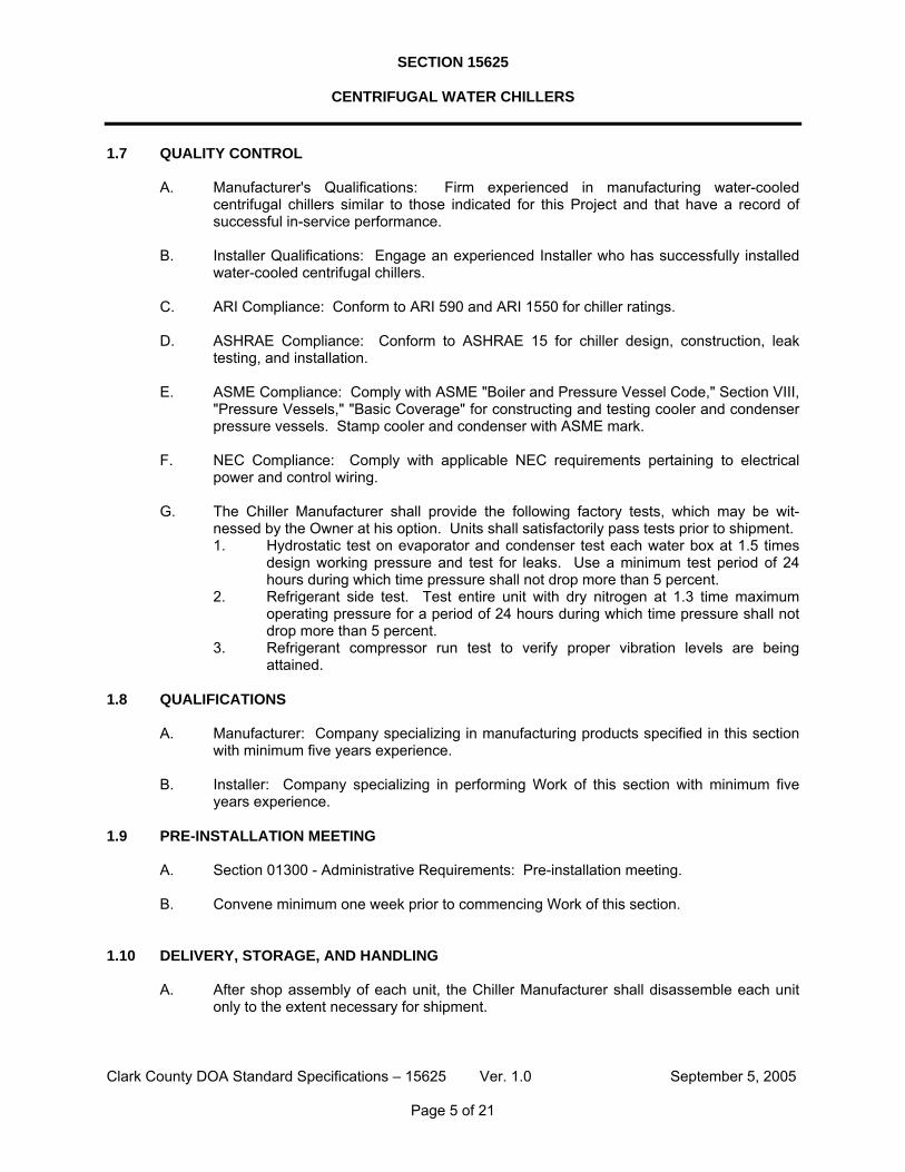
1.7 QUALITY CONTROL
A. Manufacturer's Qualifications: Firm experienced in manufacturing water-cooled centrifugal chillers similar to those indicated for this Project and that have a record of successful in-service performance.
B. Installer Qualifications: Engage an experienced Installer who has successfully installed
water-cooled centrifugal chillers. C. ARI Compliance: Conform to ARI 590 and ARI 1550 for chiller ratings. D. ASHRAE Compliance: Conform to ASHRAE 15 for chiller design, construction, leak
testing, and installation. E. ASME Compliance: Comply with ASME "Boiler and Pressure Vessel Code," Section VIII,
"Pressure Vessels," "Basic Coverage" for constructing and testing cooler and condenser pressure vessels. Stamp cooler and condenser with ASME mark.
F. NEC Compliance: Comply with applicable NEC requirements pertaining to electrical
power and control wiring. G. The Chiller Manufacturer shall provide the following factory tests, which may be wit-
nessed by the Owner at his option. Units shall satisfactorily pass tests prior to shipment. 1. Hydrostatic test on evaporator and condenser test each water box at 1.5 times
design working pressure and test for leaks. Use a minimum test period of 24 hours during which time pressure shall not drop more than 5 percent.
2. Refrigerant side test. Test entire unit with dry nitrogen at 1.3 time maximum operating pressure for a period of 24 hours during which time pressure shall not drop more than 5 percent.
3. Refrigerant compressor run test to verify proper vibration levels are being attained.
1.8 QUALIFICATIONS
A. Manufacturer: Company specializing in manufacturing products specified in this section
with minimum five years experience. B. Installer: Company specializing in performing Work of this section with minimum five
years experience. 1.9 PRE-INSTALLATION MEETING
A. Section 01300 - Administrative Requirements: Pre-installation meeting. B. Convene minimum one week prior to commencing Work of this section.
1.10 DELIVERY, STORAGE, AND HANDLING
A. After shop assembly of each unit, the Chiller Manufacturer shall disassemble each unit
only to the extent necessary for shipment.

SECTION 15625
CENTRIFUGAL WATER CHILLERS
Clark County DOA Standard Specifications – 15625 Ver. 1.0 September 5, 2005
Page 6 of 21
B. The Chiller Manufacturer shall mark parts of work to be erected or field-assembled durably and legibly with indelible markings, giving the Contractor's order number, detail identification, and match marking to enable the Contractor to identify the various parts and erect work without delay.
C. The Chiller Manufacturer shall identify shipments from the Chiller Manufacturer and Chil-
ler Manufacturer's suppliers with the Contractor's purchase order number. The Chiller Manufacturer shall furnish a detailed list of parts in each shipment to permit satisfactory checking when received.
D. The Chiller Manufacturer shall tag and place separate parts too small to mark in con-
tainers plainly marked on outside as to contents and the Contractor's purchase order number. In shipping bolts, different kinds and sizes shall be kept separate, either by separate containers or partitions in same container.
E. Before shipment, the Chiller Manufacturer shall coat finished surfaces of machinery and
equipment thoroughly with a protective material that prevents rust, but can be readily removed when erected.
F. The Chiller Manufacturer shall protect equipment against damage during shipment and
delivery. G. The Chiller Manufacturer shall cap or plug pipe ends and tapped holes for pipe con-
nections before shipment. H. After loading equipment for shipment, the Chiller Manufacturer shall notify the Contractor
in writing via telephone facsimile transmission with the name of carrier, car number, description of equipment, order number, weight of heaviest piece, shipping point, date of shipment, and estimated time of arrival.
I. The chillers shall not be shipped until the Owner has given his verbal approval that site
has been prepared to a sufficient degree that it is ready for delivery. J. Acceptance on Site: Reject any damaged chiller upon arrival. K. Storage and Protection: Store chillers to prevent damage, and protect from weather, dirt,
fumes, water, and construction debris. Provide a clean dry space if available. L. Handling: Handle chillers according to the manufacturer's rigging and installation
instructions for unloading and transporting into the final location.
1.11 WARRANTY
A. The Chiller Manufacturer shall warrant all equipment for one (1) year and the compressor (compressor and motors) for five (5) years as described in these Specifications. Warranty period shall commence with the Owner's written acceptance of successful startup of chiller machinery, documented by a certificate of substantial completion.
B. The Chiller Manufacturer shall include in his warranty the cost of all parts, including
freight or air freight, as required to remedy any breakdown situation relating to the chiller installation.
C. The Chiller Manufacturer shall include in his warranty the cost of all labor including
traveling expenses as required to remedy any breakdown situation relating to the instal-

SECTION 15625
CENTRIFUGAL WATER CHILLERS
Clark County DOA Standard Specifications – 15625 Ver. 1.0 September 5, 2005
Page 7 of 21
lation. The Chiller Manufacturer's service personnel shall be "On Call" 24 hours per day and 7 days per week including holidays. The Chiller Manufacturer shall be reimbursed for the difference in costs between normal rate and premium time when warranty work is required outside of normal working hours.
D. The Chiller Manufacturer shall correct all critical defects and water and refrigerant leaks
within 24 hours or less following the Owner's verbal notification of a problem for a period of one (1) year after acceptance by the Owner. A "critical defect" shall be defined as a chiller defect resulting in the inability to maintain temperature below 50 degrees F.
E. The Chiller Manufacturer shall correct all non-critical defects discovered in the chiller
installation within 30 days following the Owner's written notice for a period of one (1) year after acceptance by the Owner. Acceptance date shall be considered date of issue of a certificate of substantial completion.
F. Failure of the Chiller Manufacturer to provide warranty work within a reasonable time
shall render his conduct as neglect, in which case the Owner shall be entitled to proceed with the correction of such work at his discretion and backcharge the Chiller Manu-facturer and/or the Contractor cost plus 10 percent for expenses incurred.
PART 2 - PRODUCTS 2.1 MANUFACTURERS
A. Manufacturers: Subject to compliance with requirements, provide centrifugal chillers by one of the following: 1. York International Corporation. 2. Carrier. 3. Trane.
B. Provide factory assembled and tested, packaged, water cooled, liquid chillers consisting
of centrifugal compressors, compressor motor, condenser, evaporator, refrigeration accessories, instrument and control panel including gages and indicating lights, auxiliary components and accessories, and motor starters.
C. Use Energy Efficiency Ratings not less than prescribed by ASHRAE 90.1. D. Conform to ASHRAE 15 code for construction and operation of chillers. Provide ASME
U-1 stamp. 2.2 WATER-COOLED CENTRIFUGAL CHILLERS - GENERAL
A. The Chiller Manufacturer shall furnish and deliver centrifugal water chillers as scheduled
on the Drawings. Each chiller shall be installed in accordance with this Specification and shall produce the specified tonnage with performance equal to or better than the scheduled data or the actual contracted performance data.
B. Acceptable refrigerants shall be:
1. HFC-134a
C. Each chiller shall have a maximum rated demand of 0.69 KW/ton when operated under full load conditions as specified on the drawings.

SECTION 15625
CENTRIFUGAL WATER CHILLERS
Clark County DOA Standard Specifications – 15625 Ver. 1.0 September 5, 2005
Page 8 of 21
D. All chiller efficiency ratings for both full load and part load performance shall be certified in accordance with ARI 550-90.
2.3 EVAPORATORS AND CONDENSERS
A. Evaporators and condensers, including the heat recovery condenser, shall be of shell
and tube type designed in accordance with requirements of the ANSI/ASHRAE 15-1989 safety code and ASME code for unfired pressure vessels. Refrigerant side shall be proof-tested per applicable code or at 1.5 times maximum design working pressure but not less than 45 psig. A safety rupture disc or safety relief valve in accordance with ANSI/ASHRAE 15-1989 safety code shall be provided for the refrigerant circuit.
B. Evaporators shall be designed for 250 psig maximum working pressure and water piping
connections shall be grooved. C. Condensers shall be designed for 250 psig maximum working pressure and water piping
connections shall be grooved. D. Water side of evaporators and condensers shall be hydrostatically tested at 1.5 times
working pressure. E. Tubes shall be internally smooth or internally enhanced tubes at the Chiller Manu-
facturer's option. The minimum tube wall thickness shall be .028 inches. F. The condensers connected to the cooling tower water system shall be provided with
marine style water boxes with removable gasketed steel plate water box covers exposing all tubes without disturbing water piping connections.
G. Water connections shall be provided with taps for air vents and drains. Relief valves set
at 150 psig shall be provided. Refer to Section 15181 "Hydronic Piping" for hydronic system pressure relief valve requirements.
H. Liquid refrigerant entering evaporator shall be distributed uniformly over the entire length
of shell and without direct impingement of high velocity refrigerant on tubes. I. Evaporators operating with refrigerants under vacuum at 75 deg. F shall be provided with
an electrically operated sump heater to raise the refrigerant temperature to equal that of the adjacent atmosphere (14.7 psia) to reduce the infiltration of air and non-condensables into the evaporator shell when the chiller is not in use.
2.4 CENTRIFUGAL COMPRESSOR
A. The compressor will be a single stage centrifugal type powered by an open drive electric motor. Hermetic compressors are not acceptable. The housing will be fully accessible with vertical circular joints, with the complete operating assembly removable from the compressor and scroll housing. Compressor castings will be designed for 180 psig working pressure and hydrostatically pressure tested at 270 psig for R-134A units. The rotor assembly will consist of a heat treated alloy steel drive shaft and impeller shaft with a cast aluminum, fully shrouded impeller. The impeller will be designed for balanced thrust, dynamically balanced and overspeed tested for smooth, vibration free operation. Insert type journal and thrust bearings will be fabricated of aluminum alloy, precision bored and axially grooved.

SECTION 15625
CENTRIFUGAL WATER CHILLERS
Clark County DOA Standard Specifications – 15625 Ver. 1.0 September 5, 2005
Page 9 of 21
Internal single helical gears with crowned teeth will be designed so that more than one tooth is in contact at all times to provide even load distribution and quiet operation. Each gear will be individually mounted in its own journal and thrust bearings to isolate it from impeller and motor forces. Shaft seal shall be provided in double bellows, double-seal, cartridge type. A gravity fed oil reservoir will be built into the top of the compressor to provide lubrication during coastdown in the event of a power failure.
Capacity control will be achieved by use of prerotation vanes to provide fully modulating
control from maximum to minimum load. The unit will be capable of operating with lower temperature cooling tower water during part load operation in accordance with ARI Standard 550/590. Prerotation vane position will be automatically controlled by an external electric actuator to maintain constant leaving chilled water temperature.
B. Lubrication oil shall be force-fed to all compressor bearings, gears, and rotating surfaces
by an external variable speed oil pump. The oil pump shall vary oil flow to the compressor based on operating and stand-by conditions, ensuring adequate lubrication at all times. The oil pump shall operate prior to start-up, during compressor operation and during coastdown. Compressor shall have an auxiliary reservoir to provide lubrication during coastdown in the event of a power failure.
An oil reservoir, separate from the compressor, shall contain the submersible 2 HP oil
pump and a 300 watt oil heater, thermostatically controlled to remove refrigerant from the oil. The oil reservoir shall be designed and stamped in accordance with ASME or applicable pressure vessel code. A non-code reservoir is not acceptable.
Oil shall be filtered by an externally mounted ½ micron replaceable cartridge oil filter
equipped with service valves. Oil cooling shall be done via a refrigerant cooled oil cooler, with all piping factory installed. Oil side of the oil cooler shall be provided with service valves. An automatic oil return system to recover any oil that may have migrated to the evaporator shall be provided. Oil piping shall be completely factory installed and tested.
C. Refrigerant: HFC-134a field charged
2.5 COMPRESSOR MOTOR AND DRIVE
A. Compressor motor and drives shall be open type in design. Speed increaser drives
(where required) shall be gear type. B. Open motors shall be open drip proof or totally enclosed fan cooled squirrel cage induc-
tion type available through nationally known manufacturers. 1. All open motors shall be built in accordance with the latest NEMA and IEEE stan-
dards. Motors shall have a guaranteed minimum full load efficiency of 93.6 percent as determined by the NEMA Standard MG-1 12.53a, Test Method F, and labeled in accordance with NEMA 1-12.53b.
2. All open motors shall be rated for continuous duty at full load at 40 deg. C ambient temperature. Motors shall operate without undue noise. Lubricating devices shall be located so as to be easily accessible.
C. A method of sensing motor winding temperature of each phase shall be provided. This
device shall independently stop the motor if excessive temperature is sensed in any of the three windings.

SECTION 15625
CENTRIFUGAL WATER CHILLERS
Clark County DOA Standard Specifications – 15625 Ver. 1.0 September 5, 2005
Page 10 of 21
D. The motor terminal connection box shall be oversized to facilitate the installation of the wiring.
E. Speed increaser drives shall be provided as an integral part of the compressor where re-
quired by the compressor design. 1. Drive gears shall be helical type designed so that more than one tooth is in
contact at all times to provide even distribution of the load. Gear sets shall be designed with a minimum service factor of 1.25. Drive shall operate at any speed and load within specified capacity without excessive noise or vibration.
2.6 EXPANSION VALVE
A. Expansion valve shall be the Chiller Manufacturer's standard expansion device.
2.7 LUBRICATION SYSTEM
A. The lubrication system shall be of the force feed type with an oil pump supplying oil under
pressure to all bearings, gears and rotating surfaces. The oil pump shall be external to the compressor. The lubrication system must provide a positive supply of oil to all bear-ings even during a power failure shutdown. A replaceable external oil filter with provi-sions for servicing without removing the unit refrigerant charge shall be provided. The oil pump shall be suitable for operation on 120-volt single or voltage as scheduled for 3-phase power. The single phase power shall be supplied through the chiller control power transformer.
B. Oil cooling shall be included. This may be either an integral cooling system or a separate
oil cooling system. For water-cooled systems, the Contractor shall provide all operating valves and controls as required to operate this system.
C. Provisions shall be included for controlled heating of oil. Heater shall be selected to
maintain oil at sufficient temperature level to minimize affinity for refrigerant.
2.8 PURGE SYSTEM
A. Chillers operating with refrigerant under vacuum at 75 F shall have purge system operated by a motor driven purge compressor and the following other items: 1. Sight glass oil level indicator. 2. Electrically heated oil separator. 3. Sectionalized drum permitting separation of condensable gases and water from
discharge of compressor purge. 4. Means for returning refrigerant to evaporator and for drawing off
non-condensables. 5. Solenoid refrigerant valve to automatically isolate purge system from centrifugal
machine when purge compressor is not in operation. 6. Air cooled or water cooled refrigerated condensing machine for separating
refrigerant, water, and non-condensables; water connections for water cooled equipment shall be provided to allow operation of the purge system when centrifugal machine is not in operation.
7. Operating start counter indicating the total number of cumulative time the purge unit has started.
8. A set of terminals shall be provided to start the purge unit via a time clock or the future BDDC System when the chiller is not in operation.

SECTION 15625
CENTRIFUGAL WATER CHILLERS
Clark County DOA Standard Specifications – 15625 Ver. 1.0 September 5, 2005
Page 11 of 21
2.9 CONTROL PANEL
A. The chiller shall be equipped with an electronic or a microprocessor based control panel. The microprocessor-based control system, control interlock wiring and single point field power connection shall be located in a dust-proof enclosure. Panel access doors shall key lock and shall include steel rod door retainers. Dead front panels shall protect service personnel against contact with line voltage components. The control components shall include the following: 1. Three-phase electronic current limiting with individual current transformers.
a. Electronic current limiter shall limit the maximum amperage drawn by the compressor motor by monitoring at least one of 3 phases of supply power. The capacity control shall modulate in response to the amperage drawn to maintain no more than maximum amperage drawn at full load.
b. Continuous variable position demand limiter shall permit manual control of power demand at all operating points from 40 to 100 percent of full load power. In addition to this manual control, remote control of power demand shall be provided by sensing a 4-20 milliamp external signal provided by the future BDDC System.
2. Electronic Capacity Control a. Self-contained electric temperature control system shall include
temperature sensor, vane actuator, integrated solid state circuit or micro-processor and any other controls necessary for capacity control.
b. Precise control of deadband range shall be field adjustable from plus or minus 1/4 deg. F to plus or minus 1-1/2 deg. F.
c. Precise control of rate at which the chiller is allowed to load (ramp function) shall be field adjustable from 2 to 45 minutes.
d. Unit controller shall include a manual four-position (hold, load, unload or automatic) diagnostic switch for ease of maintenance.
e. Individual lights shall indicate when machine is loading, unloading, or if automatic current limiting is occurring.
3. An output device capable of delivering read only information in ASCII format shall be provided. The information made available shall include all pertinent data which is normally read and used by the chiller control system. Provide software translation information for converting available raw signals to meaningful information. Output device may be an RS232 port.
4. Low refrigerant temperature (or pressure) override shall automatically close the guide vanes and unload the compressor if low refrigerant temperature is detected.
5. A method to maintain capacity inlet guide vanes in closed position during compressor startup shall be provided for normal compressor startup and startup after a power failure.
6. Anti-recycle timer to ensure 30-minute interval between successive compressor motor starts.
7. Individual, front adjustable gauges shall be provided to indicate condenser, evaporator, oil and purge drum pressures. Gauges shall be scaled in English units. Gauges shall be orificed to prevent excessive sensitivity and movement of gauge indicators.
8. Oil pump timer shall provide operation of oil pump during prelube and postlube cycles.
9. Switch to permit manual or automatic operation of the purge system. A means shall be provided to operate purge system automatically during "winter" shut down periods from an external signal from a time clock or from the future BDDC System.
SECTION 15625
CENTRIFUGAL WATER CHILLERS
Clark County DOA Standard Specifications – 15625 Ver. 1.0 September 5, 2005
Page 12 of 21
10. Safety controls shall be wired in the main control power circuit to the starter. Low evaporator temperature, high condenser pressure, high motor temperature and low oil pressure controls shall be wired to independently stop the compressor motor. A method to provide first-out indication of fault shall be provided. Manual reset of each fault trip indicator shall be required.
11. Starter panel faults which are detected shall be wired to a starter fault trip indicator which shall stop the compressor motor. Manual reset shall be required.
12. The external flow switches for the evaporator and condenser water circuits shall be wired to the chiller control panel and shall stop the chiller on flow failure. Automatic reset shall be provided.
13. An evaporator return water temperature sensor shall be provided which will sense the return water temperature and shall turn the chiller "off" when the temperature is less than the evaporator discharge temperature. This shall be a manually adjustable single setpoint device.
14. An ON-OFF-AUTO switch shall be provided in the chiller panel. With the switch in the AUTO position, the chiller shall be capable of being started remotely. With the switch in the ON or OFF position, the chiller shall be controlled locally and a signal to the future BDDC System indicating the chiller is not in automatic control shall be provided.
15. The control panel shall be interfaced with a chilled water plant operating and optimization system provided via the (future) BDDC System. Each chiller shall be capable of operating in conjunction with or independently from this system. The Chiller Manufacturer shall provide all binary contacts, analog signal receivers (4 to 20 milliamps), and analog outputs necessary to operate and monitor the chillers from the independent system. These inputs and outputs shall include: a. Digital Input - Chiller Start/Stop b. Analog Input - Leaving Evaporator Water Temperature Reset (4-20 ma) c. Analog Input - Demand Limiting Signal (4-20ma) d. Analog Output - (from wattmeter) Chiller Power Consumption (4-20ma -
see "Chiller Starters") e. Digital Output - Chiller Running/Stopped f. Digital Output - Chiller Safety Control Failure
16. Each chiller safety and operating device mounted outside the control panel and each device requiring field wiring connections shall be wired back to a numbered terminal block in the chiller control panel. Each device shall have its own set of terminals for easy isolation of each device.
2.10 CHILLER STARTERS - 4160 VOLT
A. Compressor motor starters shall be supplied by the Chiller Manufacturer. Starters shall be primary reactor (closed transition) type and shall be enclosed in freestanding NEMA-1 enclosures. Each starter shall have an interrupting rating of 200,000 KVA minimum at 4160 volts.
B. The starter panel door shall be hinged and shall be capable of being locked with Kirk Key
interlock to prevent access whenever the supply power switch is "ON". C. The ambient temperature inside the starter panel shall not exceed 155 deg. F (67 deg. C)
with all components energized at rated load conditions and 104 deg. F (40 deg. C) ambient outside the starter panel. Temperature rise of components shall be per related NEC, NEMA and UL codes.
SECTION 15625
CENTRIFUGAL WATER CHILLERS
Clark County DOA Standard Specifications – 15625 Ver. 1.0 September 5, 2005
Page 13 of 21
D. A permanent nameplate shall be provided and mounted on the starter panel. It shall identify the manufacturer, serial or model number identifying the date of manufacture and component replacement parts and all current and voltage ratings.
E. Permanent schematic and connection wiring diagrams shall be provided. They shall indi-
cate exactly how the starter was manufactured and wired including the wire terminal numbers. Generic diagrams will not be acceptable.
F. Power supply terminals shall be identified by permanent markers. The maximum temper-
ature of terminals shall not exceed 167 deg. F (75 deg. C) when the equipment is tested in accordance with its rating.
G. The isolating switch shall be externally operated manual three-pole drawout unit that, in
the open position, completely grounds and isolates the starter from the line connectors with a mechanically driven isolating shutter leaving no exposed high voltage. Integral mechanical interlocks shall prevent entry into high voltage areas while the starter is energized and shall block accidental opening or closing of isolating switch when door is open or contactor is closed. Isolating switch handle shall have provisions for three pad-locks.
H. Current limiting power fuses shall be of the self-protecting type with visible fuse condition
indicators and with special time/current characteristics for motor service allowing proper coordination with contactor and overload relay for maximum motor protection. The power fuses shall be vertically mounted permitting an easy inspection and replacement without starter disassembly.
I. Contactors shall be drawout, air break type, with main contacts single break high
pressure type with weld-resistant silver alloy contact faces. They shall be rated in voltage, continuous rated load amperes (RLA) and locked rotor amperes (LRA). The rating shall be equal to or greater than the requirements specified on the compressor motor nameplate.
J. All wires, bus bars and fittings shall be copper. K. A 120-volt single-phase 60 hertz power supply(s) for chiller auxiliaries including purge
pumps, oil heaters, evaporator heaters, oil pump, all control relays and indicating lights located in the starter and all indicating control relays and indicating lights located in the control panel shall be developed within the three-phase compressor motor starter and shall be in accordance with the Chiller Manufacturer's specifications. All controls shall be wired to a terminal strip common location and using an electric relay, the controls shall be capable of being energized from an external power source when the starter is de-energized. 1. All 120 volt power supplies shall be individually fused using circuit breakers, for
each of the following: control circuit, oil pump system circuit, oil heater circuit, evaporator heater, and purge circuit as applicable.
L. Starters shall be provided with a lockout transition safety circuit which shall prevent dam-
age from prolonged energization due to malfunction of the transition contactor. Mal-function shall cause the machine to be shut down and the "starter circuit fault" indicator to be displayed.
M. The electronic, three-phase overload system shall provide protection to the compressor
motor with three overloads.
SECTION 15625
CENTRIFUGAL WATER CHILLERS
Clark County DOA Standard Specifications – 15625 Ver. 1.0 September 5, 2005
Page 14 of 21
1. The overload system shall be coordinated with the current control system to provide fail-safe circuitry. Single or multiple adjustment(s) shall be used to set all three overloads and the current control signal. All three phases shall be monitored and the highest output shall be used in the overload and current control systems.
2. The electronic overload system shall be coordinated with the compressor motor and factory set and labeled with the compressor motor rated load amps (RLA), locked rotor amps (LRA) and overload trip (OLT) setting.
3. The electronic overload system shall provide: a. Excessive locked rotor current protection. b. Excessive locked rotor time protection. c. Current control of transition from start to run configuration. d. Maximum current protection to prevent the compressor motor from
exceeding its OLT setting. e. Protection of equipment against transition resistor failure.
4. A "motor overload" fault trip indicator shall be displayed if any of the above condi-tions are sensed and shall cause the machine to be shut down. Electronic digital timing shall be provided by the overload system for repeatability and accuracy.
5. The electronic, three-phase overload system shall be field adjustable for purposes of coordination with other electrical protection devices.
N. Distribution fault protection shall be provided to prevent the increasingly common rapid
reclosure of power distribution systems from adversely affecting the mechanical and power drive equipment. The distribution fault protection shall consist of three-phase current sensing and monitoring the status of the starter. Distribution faults of 1-1/2 elec-trical cycles duration shall be detected and the compressor motor shall be disconnected within six electrical cycles. If a distribution fault is detected, the fault trip indicator "dis-tribution fault" shall be displayed and manual reset shall be required.
O. Ground fault protection shall be provided. This device shall trip when the dielectric
resistance of the three-phase circuit is significantly reduced in either the starter or the compressor motor. If a ground fault is detected, the chiller shall be shut down and the "ground fault" indicator shall be displayed.
P. Low voltage protection shall be provided. This device shall be separate from any other
safety device and shall function on a time-voltage curve which will allow low voltage conditions to exist for the degree of time which is inversely proportional to the deviation from the normal voltage. Upon detection of a low voltage condition, the device shall shut down the chiller and a "Low Voltage Condition" indicator shall be displayed.
Q. Phase failure and phase reversal protection shall be provided. This device shall be
separate from any other safety device and shall shut down the compressor if a phase failure or phase reversal occurs and a "Phase Failure" indication shall be displayed.
R. A large "Emergency Off" pushbutton shall be provided on the starter enclosure. Upon
manual actuation of this pushbutton, the device shall shut down the machine and a "Emergency Stop" indicator shall be displayed.
S. All starter safety and protection devices shall be provided with visual indicators consisting
of starter enclosure mounted indicating lights or panel-mounted circuit breakers with toggle switches. Upon detection of a safety device failure, the machine shall be shut down, the particular failure indicator shall be displayed, and a dry-contact (interlocked with the chiller control console "starter failure" relay) shall close. Each device shall be connected to a system with a "First Out" feature which will indicate which device failed

SECTION 15625
CENTRIFUGAL WATER CHILLERS
Clark County DOA Standard Specifications – 15625 Ver. 1.0 September 5, 2005
Page 15 of 21
first. The fault indicator will remain "ON" until the toggle switch is reset (as applicable) or a reset pushbutton is pushed. A means shall be provided to test all indicating lights to check for burned out bulbs.
T. The compressor motors shall each be provided with capacitors to provide power factor
correction to 95 percent (lagging) with motor operation at full load. The capacitors shall be mounted in the starter.
U. Each starter shall be provided with the following meters.
1. Ammeters - One ammeter shall be provided for each machine, complete with 4-position switch. Ammeters shall be calibrated so that normal operating current can be indicated, and so normal starting current does not damage meter.
2. Voltmeters - One voltmeter shall be provided for each machine, complete with 4-position switch.
3. In addition to individual ammeters and voltmeters, each starter shall be provided with an electronic digital wattmeter device. This device shall have a 4-20 milliamp output signal to monitor power consumption. Accuracy of the unit shall be +0.09%. Unit shall be equal to Rochester Instrument Systems Series PCM Electronic Watt Transducer.
4. Each starter shall be provided with a test block with terminals for metering individual leg amperes and volts with a portable instrument from the outside of the starter.
V. All starter mounted safety and operating control devices and each device requiring field
wiring connections shall be wired back to a numbered terminal block. Each device shall have its own set of terminals for easy isolation of each device.
W. Terminal connection pads shall be provided to which applied lugs attached. The terminal
connections for underground power feeds to the starter shall be provided with stress cones.
2.11 MISCELLANEOUS REQUIREMENTS
A. Each chiller shall be provided with a refrigerant sight glass and an oil sight glass. B. Each chiller shall be furnished with the Chiller Manufacturer's standard paint finish. C. If furnished as standard feature or option, each chiller shall be furnished with factory-
applied insulation on all cold surfaces. Refer to Section 15083 "HVAC Insulation" for further requirements.
D. Each chiller shall be furnished with vibration isolators under Section 15074 "Vibration and
Seismic Controls for HVAC Piping and Equipment". E. Nameplates - each chiller shall bear firmly attached metal plates which state name of
manufacturer, chiller unit model number, chillier unit serial number, compressor type, and refrigerant used., refer to Section 15075 “Mechanical Identification”.
F. All gauge tubing shall be installed using hard copper tubing. Bends and turns shall be made with fittings or by bending tubing using tools.
G. The evaporator and condenser water circuits shall each be provided with differential
pressure switches as a means of proving flow through the evaporator and condensers.

SECTION 15625
CENTRIFUGAL WATER CHILLERS
Clark County DOA Standard Specifications – 15625 Ver. 1.0 September 5, 2005
Page 16 of 21
H. Where 460 volt auxiliary motor-driven devices are provided as a part of the Chiller Manufacturer's standard offering, the Chiller Manufacturer shall provide individual starters with HAND-OFF-AUTO switches for each device. Refer to Section 15055 "Motors" for further requirements.
2.12 REFRIGERANT PUMPOUT
A. The project shall be furnished with one portable pumpout system or with individual chiller
mounted pumpout units. Each system shall be complete with transfer pump, condensing unit and storage vessel constructed in accordance with ASME code for unfired pressure vessels and with the National Board Stamp. Pumpout tanks shall be ASME stamped. This (these) pumpout system(s) shall be used to remove and store refrigerant from the centrifugal machines. Pumpout system all be supplied and warranted by the Chiller Manufacturer. 1. When pumpout units are installed on individual chillers, pumpout tanks shall be
capable of holding the refrigerant charge of one machine when 90 percent full at 90 deg. F.
2. When portable pumpout units are provided, the unit shall be set on casters or wheels and shall be provided with a tongue or similar device for pulling the unit and directing its motion. The portable pumpout unit shall be complete with water-cooled condenser, compressor, valving, and sufficient hosing and power cord for servicing each chiller when the pumpout unit is located in the service aisle. Pumpout compressor shall operate on 208 volt, 3 phase, 60 hertz power (5 horsepower maximum). Each compressor shall be provided with a motor starter and a plug and cord. Coordinate plug requirements with the Electrical Contractor.
B. Separate charging connections shall be provided for both liquid and gaseous refrigerant. C. Piping between individual pumpout units and chiller shall be provided by the Chiller
Manufacturer. The Chiller Manufacturer shall provide all piping, electrical equipment, and wiring required. Refrigerant piping shall be Type K hard-drawn copper with wrought copper fittings. Valves shall be packless type suitable for refrigerant use. Refrigerant service hose shall be as recommended by the Chiller Manufacturer.
2.13 REFRIGERANT LEAK DETECTION UNIT
A. The Chiller Manufacturer shall furnish one halogen-selective refrigerant leak detection
unit suitable for area monitoring. Halogen specific detectors shall use a specialized sen-sor that allows the monitor to detect compounds containing fluorine, chlorine, bromine, without being activated by other chemical compounds. The detectors shall be capable of being calibrated in the field.
B. The unit shall meet the following specifications:
Power Supply - 120V - 1 phase - 60 hertz
Outputs - 2A dry contact and 4-20 mA analog output
Measuring Range - 0-300 PPM for halocarbons
Accuracy - +10% of scale

SECTION 15625
CENTRIFUGAL WATER CHILLERS
Clark County DOA Standard Specifications – 15625 Ver. 1.0 September 5, 2005
Page 17 of 21
Alarm set - 10 to 100% of scale (adjustable)
C. The unit shall be provided complete with 12/24 DC power supply as required for con-verting 120 volt AC power to DC power.
D. The unit shall be suitable for ambient operating temperatures between 50 deg. F and 104
deg. F. E. The unit shall include a face mounted concentration meter, power "on" indicating light
and an audible and visual alarm. The unit shall be mounted in a NEMA 1 enclosure. F. The sensor shall be a rugged remote mounted device with a minimum 3-year lifetime. G. The unit shall be furnished complete with a gas calibration kit.
PART 3 - EXECUTION 3.1 EXAMINATION
A. Examine areas to receive chillers for compliance with requirements for installation tolerances and other conditions affecting chiller performance. Examine proposed route of moving chillers into place and verify that it is free of interferences. Verify piping rough-in locations. Verify branch circuit wiring suitability. Do not proceed with installation until unsatisfactory conditions have been corrected.
B. Final locations of the chillers on the Drawings are approximate, unless dimensioned.
Determine exact locations before roughing-in piping and electrical work.
3.2 INSTALLATION
A. Install chillers according to manufacturer's written instructions. B. Install and anchor chillers plumb and level. C. Install vibration isolators according to isolator manufacturer's recommendations. D. Maintain manufacturer's recommended clearances for service and maintenance. E. Install piping connections, maintaining clearances for service and maintenance. F. Install flanged or union connections at chillers. G. Install flexible pipe connections for chillers mounted on vibration isolators. H. Install shutoff valves at chiller inlet and outlet connections. I. Field-insulate cooler, suction lines, and other surfaces where condensation might occur. J. Electrical Wiring: Install electrical devices furnished loose by manufacturer, including
remote flow switches and remote chiller control panel. Furnish copy of manufacturer's wiring diagram submittal to electrical Installer.

SECTION 15625
CENTRIFUGAL WATER CHILLERS
Clark County DOA Standard Specifications – 15625 Ver. 1.0 September 5, 2005
Page 18 of 21
3.3 STARTUP SERVICE
A. The Chiller Manufacturer shall provide startup service for each unit provided. Refer to Section 15995 “Commissioning of Mechanical Systems”.
B. Startup service shall include the following:
1. Provide a factory trained service representative employed by the Chiller Manu-facturer to supervise the chiller installation work provided by the Contractor.
2. After the Contractor has installed the mechanical portion of chillers on level bases, factory trained service mechanics employed by the Chiller Manufacturer shall leak test, refrigerant pressure test, evacuate, dehydrate, and charge each machine with refrigerant.
3. The Contractor and his subcontractors shall provide all water piping connections and control wiring connections and shall verify all water flow rates prior to final startup.
4. After the Contractor has provided all water piping connections and field control wiring and the Electrical Contractor under Division 16 has provided all the field power wiring as shown on the Chiller Manufacturer's installation drawings (all electrical wiring shall be tagged, checked out and connected as indicated on the Chiller Manufacturer's Drawings), the factory trained service representative employed by the Chiller Manufacturer shall verify all piping and wiring connections, verify all water flow rates, operate the chillers, test each safety device, and calibrate all controls.
5. The factory trained service representative employed by the Chiller Manufacturer shall perform the following tests and services and submit a report outlining results. a. Log unit running hours, date, time, and person performing service. b. Lubricate all moving parts. c. Check refrigerant charge and supply additional refrigerant as required. d. Check operation of purge unit and purge non-condensables to insure
optimum performance. e. Check compressor oil level and supply additional oil as required. Check
operation of oil pump, oil heater, and oil cooler. f. Check motor alignment on open-drive equipment and re-align as
required. g. Check motor and starter power lugs and tighten as required. h. Conduct a startup inspection including a complete log of water flow,
temperature, pressure, and power readings. These readings shall be used as a basis for analysis of readings taken throughout the operating season.
i. Check and adjust, repair, or replace as necessary all capacity, temperature, and safety controls, including thermometers and gauges which are a part of equipment provided in this contract.
j. Perform vibration analysis at each bearing location, include a log of vibration amplitudes in a minimum of two (X-X and Y-Y) directions at each point.
k. Conduct a meg-ohm stator winding test on compressor motors. 6. Calibrate refrigerant leak detection unit. 7. Operate each unit for 72 hours minimum prior to final inspection. At final inspec-
tion tabulate data above and provide three (3) certified copies of the test data to the Owner.

SECTION 15625
CENTRIFUGAL WATER CHILLERS
Clark County DOA Standard Specifications – 15625 Ver. 1.0 September 5, 2005
Page 19 of 21
3.4 FIELD QUALITY CONTROL
A. Manufacturer's Field Service: Provide services of a factory-authorized service representative to supervise the field assembly of components and installation of chillers, including piping and electrical connections, and to report results in writing.
3.5 CLEANING
A. Clean units using materials and methods recommended by manufacturer. B. Clean finishes to remove dust and dirt. C. Touch up scratches on unfinished surfaces to restore corrosion resistance. D. Touch up scratches on finished surfaces to restore finish.
3.6 DEMONSTRATION
A. Startup Services: Provide factory-authorized service representative to start chillers and
to demonstrate and train Owner's maintenance personnel as specified below: 1. Test and adjust chiller controls and safeties. Lubricate rotating parts. Verify that
motor amperage conforms to manufacturer's data. 2. Start chiller and verify performance. Demonstrate operation to Owner. 3. Train Owner's maintenance personnel on procedures and schedules for startup,
shutdown, troubleshooting, servicing, and preventive maintenance. Training shall consist of two separate sessions, dates selected by the Owner. All testing and adjusting shall be complete prior to instructions. The instructor shall be thoroughly familiar with all parts of the installation on which he is to give instruction and shall be trained in operating theory as well as in practical operation and maintenance work. Factory trained instructors shall be employed. Instruction shall occur during the regular workday. Instruction shall be completed prior to the final acceptance of the equipment.
4. Review data in operating and maintenance manuals. Refer to Section "Operating and Maintenance Data."
5. Schedule training with the Owner with at least 7 days notice. 3.8 MAINTENANCE CONTRACT
A. The chillers shall be operated year round. Scheduling of all maintenance shall be
coordinated in advance with the Owner. A minimum 15 day notice shall be arranged and approved by Owner for all Maintenance Contract Scheduling Work.
B. In addition to the initial equipment start-up the following annualized maintenance
procedures shall be performed by the Chiller Manufacturer's service representative on the schedule outlined:
C. Perform the following operations and submit a report on the applicable tests. Operations
shall be performed four (4) times during the year. 1. Log unit running hours, date, time, and person performing service. 2. Lubricate all moving parts. 3. Check operation of purge unit and purge non-condensables to insure optimum
performance.

SECTION 15625
CENTRIFUGAL WATER CHILLERS
Clark County DOA Standard Specifications – 15625 Ver. 1.0 September 5, 2005
Page 20 of 21
4. Check for refrigerant leaks, repair leaks, and replace any refrigerant lost due to leaks and/or purge system to insure optimum performance. Supply new refrigerant as required.
5. Determine level of condenser tube fouling. 6. Supply new compressor oil, oil filters, refrigerant filters and filter dryers on basis
recommended by the Chiller Manufacturer, based on unit running hours and based on anticipated running hours for upcoming maintenance interval.
7. Check and adjust, repair, or replace as necessary all capacity, temperature, and safety controls, including thermometers and gauges which are a part of equipment provided in this contract.
8. Operate the chiller and tabulate all pressure, temperature, and power readings. 9. Notify Owner of any manufacturer modifications as they become available for
purchase, to update or protect listed equipment. 10. Perform vibration analysis at each bearing location, including a log of vibration
amplitudes in a minimum of two (X-X) and (Y-Y) directions at each point. 11. Provide applicable tests, as required, to analyze Owner reported problems, i.e.,
excessive compressor noise/vibration, etc.
D. The Chiller Manufacturer's service representative shall perform the following operations and submit a report on the applicable tests. Operations shall be performed on an annual basis. 1. Log unit running hours, date, time and person performing service. 2. Furnish chemical analysis and report on compressor oil and refrigerant. Replace
contaminated fluids. Furnish any corrective steps to insure optimum equipment performance and reliability.
3. Furnish visual tube inspection of condenser tubes and mechanically brush clean condenser tubes.
4. Conduct a meg-ohm stator winding test on compressor motors. 5. Check motor and starter power lugs and tighten as required. 6. Check motor alignment on open-drive equipment and re-align as required. 7. Conduct a startup inspection including a complete log of temperature, pressure,
and power readings. These readings shall be used as a basis for analysis of readings taken throughout the operating season.
8. Paint equipment where surface coating has deteriorated.
E. The following items shall be performed or shall be available to the Owner at additional cost. The Chiller Manufacturer shall initially recommend frequency at which eddy current tests should be performed and he shall notify The Owner of availability of an Extended Service Contract covering portions of work listed hereafter a minimum of 3 months prior to the expiration date of the Parts and Service Warranty. 1. Eddy current tube testing for detection of wear, pitting and corrosion in
evaporator and condenser tubes. 2. Emergency service between regular inspections if not covered under warranty. 3. Non-moving parts service coverage to repair/replace parts such as tubes,
stators, shells, etc., if not covered under warranty. 4. Miscellaneous parts for control panel and purge unit service coverage to
repair/replace parts such as relays, controls, purge unit, etc., if not covered under warranty.
F. Maintenance Contract period shall commence with acceptance of successful startup for
each piece of equipment. Maintenance Contract shall be in force for one (1) year as pro-vided in these specifications.

SECTION 15625
CENTRIFUGAL WATER CHILLERS
Clark County DOA Standard Specifications – 15625 Ver. 1.0 September 5, 2005
Page 21 of 21
G. The Chiller Manufacturer shall include in this Contract, the cost of all labor including traveling expenses and all freight required to deliver parts, fluids, and testing equipment to the site.
H. All maintenance work shall be performed by factory trained service mechanic(s) em-
ployed by the Chiller Manufacturer during normal working hours. I. Failure by the Chiller Manufacturer or the Contractor to provide maintenance work within
30 days of "normal" schedule shall render his conduct as neglect, in which case the Owner shall be entitled to proceed with such work at his discretion and back charge the Contractor and/or the Chiller Manufacturer at cost plus 10 percent for expenses incurred.
J. Inspection reports provided as a portion of the work shall include all equipment data logs,
pertinent test data and results and shall include recommendations for reducing energy consumption. Report shall be submitted to the Owner within 30 days of service work.
END OF SECTION