Section 13 Guidelines For The Design Of Ground … · ... the 2001 AASHTO Standard Specifications...
16
BDC09MR-03 NJDOT Design Manual – Roadway 13-1 Guidelines for the Design of Ground Mounted Sign Supports Section 13 Guidelines For The Design Of Ground Mounted Sign Supports 13.1 Introduction Highway signs fall into two main categories, which are subdivided as follows: 1. Overhead Signs a. Sign Bridge Structures (GO) b. Sign Cantilever Structures (GO) c. Bridge Mounted (GOX) 2. Ground Mounted Signs a. Small Highway Signs (GA) b. Large Highway Signs (GA) This section covers the design guidelines for Ground Mounted Sign Supports. These guidelines have been developed utilizing the 2006 AASHTO A Policy on Geometric Design of Highways and Streets, the 2001 AASHTO Standard Specifications for Structural Supports for Highway Signs, Luminaires and Traffic Signals, the 2002 AASHTO Roadside Design Guide, and the 2003 Manual on Uniform Traffic Control Devices for Streets and Highways (MUTCD). Design guidelines and standard drawings for overhead and cantilever signs are covered in the NJDOT General Design Criteria and Standard Drawings for Overhead and Cantilever Sign Support Structures, 2007. The designer has four options from which to choose when locating signs within the highway right-of-way. These options are: 1. Locate the sign beyond the clear zone. 2. Mount the sign overhead. 3. Utilize a breakaway support to reduce impact severity 4. Shield the sign with a longitudinal barrier and/or crash cushion Ground mounted signs should desirably be located beyond the clear zone. In addition, all ground mounted highway signs are to be installed on breakaway supports, unless otherwise indicated herein. When a small sign is located behind a traffic barrier (which is required for another reason), non-breakaway supports may be used. In cases where noise walls are required at a particular sign location, additional berm widths may be necessary. In considering the above, it is critical that sign locations and the design of the sign support be considered early in the Initial Design Development Stage. Depending upon the size of the sign, additional right-of-way, or slope easements may be required (see Standard Roadway Construction Details CD-612-4 and 7 for grading details). Also, where sign supports must be shielded, sufficient area must be provided to accommodate guide rail or a crash cushion. 13.2 Small Highway Signs Small highway signs are defined as those with total panel areas less than 50 square feet. When this category of sign is used, the design guidelines for its support shall be steel “U” post sign supports. Aluminum posts are not permitted for small highway signs. Small highway signs shall not be placed in front of guide rails, and the posts shall not straddle guide rail. All small highway sign supports shall be of
Transcript of Section 13 Guidelines For The Design Of Ground … · ... the 2001 AASHTO Standard Specifications...
BDC09MR-03
NJDOT Design Manual – Roadway 13-1
Guidelines for the Design of Ground Mounted Sign Supports
Section 13
Guidelines For The Design Of Ground Mounted Sign Supports
13.1 Introduction
Highway signs fall into two main categories, which are subdivided as follows:
1. Overhead Signs
a. Sign Bridge Structures (GO)
b. Sign Cantilever Structures (GO)
c. Bridge Mounted (GOX)
2. Ground Mounted Signs
a. Small Highway Signs (GA)
b. Large Highway Signs (GA)
This section covers the design guidelines for Ground Mounted Sign Supports. These
guidelines have been developed utilizing the 2006 AASHTO A Policy on Geometric Design of Highways and Streets, the 2001 AASHTO Standard Specifications for Structural Supports for Highway Signs, Luminaires and Traffic Signals, the 2002
AASHTO Roadside Design Guide, and the 2003 Manual on Uniform Traffic Control Devices for Streets and Highways (MUTCD).
Design guidelines and standard drawings for overhead and cantilever signs are covered in the NJDOT General Design Criteria and Standard Drawings for Overhead and Cantilever Sign Support Structures, 2007.
The designer has four options from which to choose when locating signs within the highway right-of-way. These options are:
1. Locate the sign beyond the clear zone.
2. Mount the sign overhead.
3. Utilize a breakaway support to reduce impact severity
4. Shield the sign with a longitudinal barrier and/or crash cushion
Ground mounted signs should desirably be located beyond the clear zone. In
addition, all ground mounted highway signs are to be installed on breakaway supports, unless otherwise indicated herein. When a small sign is located behind a
traffic barrier (which is required for another reason), non-breakaway supports may be used. In cases where noise walls are required at a particular sign location, additional berm widths may be necessary.
In considering the above, it is critical that sign locations and the design of the sign support be considered early in the Initial Design Development Stage. Depending
upon the size of the sign, additional right-of-way, or slope easements may be required (see Standard Roadway Construction Details CD-612-4 and 7 for grading details). Also, where sign supports must be shielded, sufficient area must be
provided to accommodate guide rail or a crash cushion.
13.2 Small Highway Signs
Small highway signs are defined as those with total panel areas less than 50 square feet. When this category of sign is used, the design guidelines for its support shall be steel “U” post sign supports. Aluminum posts are not permitted for small
highway signs. Small highway signs shall not be placed in front of guide rails, and the posts shall not straddle guide rail. All small highway sign supports shall be of
BDC09MR-03
NJDOT Design Manual – Roadway 13-2
Guidelines for the Design of Ground Mounted Sign Supports
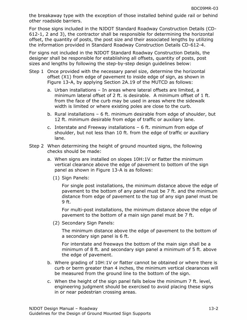
the breakaway type with the exception of those installed behind guide rail or behind other roadside barriers.
For those signs included in the NJDOT Standard Roadway Construction Details (CD-
612-1, 2 and 3), the contractor shall be responsible for determining the horizontal offset, the quantity of posts, the post size and their associated lengths by utilizing
the information provided in Standard Roadway Construction Details CD-612-4.
For signs not included in the NJDOT Standard Roadway Construction Details, the designer shall be responsible for establishing all offsets, quantity of posts, post
sizes and lengths by following the step-by-step design guidelines below:
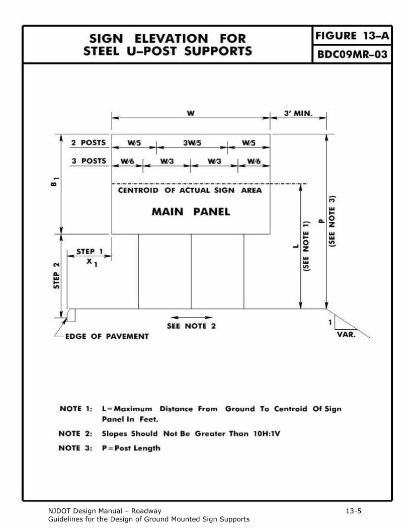
Step 1 Once provided with the necessary panel size, determine the horizontal
offset (X1) from edge of pavement to inside edge of sign, as shown in Figure 13-A, by applying Section 2A.19 of the MUTCD as follows:
a. Urban installations – In areas where lateral offsets are limited, a
minimum lateral offset of 2 ft. is desirable. A minimum offset of 1 ft. from the face of the curb may be used in areas where the sidewalk
width is limited or where existing poles are close to the curb.
b. Rural installations – 6 ft. minimum desirable from edge of shoulder, but 12 ft. minimum desirable from edge of traffic or auxiliary lane.
c. Interstate and Freeway installations – 6 ft. minimum from edge of shoulder, but not less than 10 ft. from the edge of traffic or auxiliary
lane.
Step 2 When determining the height of ground mounted signs, the following checks should be made:
a. When signs are installed on slopes 10H:1V or flatter the minimum vertical clearance above the edge of pavement to bottom of the sign
panel as shown in Figure 13-A is as follows:
(1) Sign Panels:
For single post installations, the minimum distance above the edge of
pavement to the bottom of any panel must be 7 ft. and the minimum distance from edge of pavement to the top of any sign panel must be
9 ft.
For multi-post installations, the minimum distance above the edge of pavement to the bottom of a main sign panel must be 7 ft.
(2) Secondary Sign Panels:
The minimum distance above the edge of pavement to the bottom of
a secondary sign panel is 6 ft.
For interstate and freeways the bottom of the main sign shall be a
minimum of 8 ft. and secondary sign panel a minimum of 5 ft. above the edge of pavement.
b. Where grading of 10H:1V or flatter cannot be obtained or where there is
curb or berm greater than 4 inches, the minimum vertical clearances will be measured from the ground line to the bottom of the sign.
c. When the height of the sign panel falls below the minimum 7 ft. level, engineering judgment should be exercised to avoid placing these signs in or near pedestrian crossing areas.
BDC09MR-03
NJDOT Design Manual – Roadway 13-3
Guidelines for the Design of Ground Mounted Sign Supports
Step 3 Determine the maximum distance (L) from the ground line to the centroid of the sign panel in feet and determine the sign panel area (A) in square feet.
NOTE: Sign Supports shall not be placed on slopes steeper than 10H:1V except
where grading of 10H:1V cannot be obtained or where they will be behind a traffic barrier. See Standard Roadway Construction Details CD-612-4 for the grading detail.
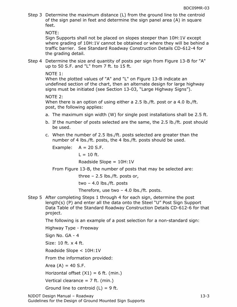
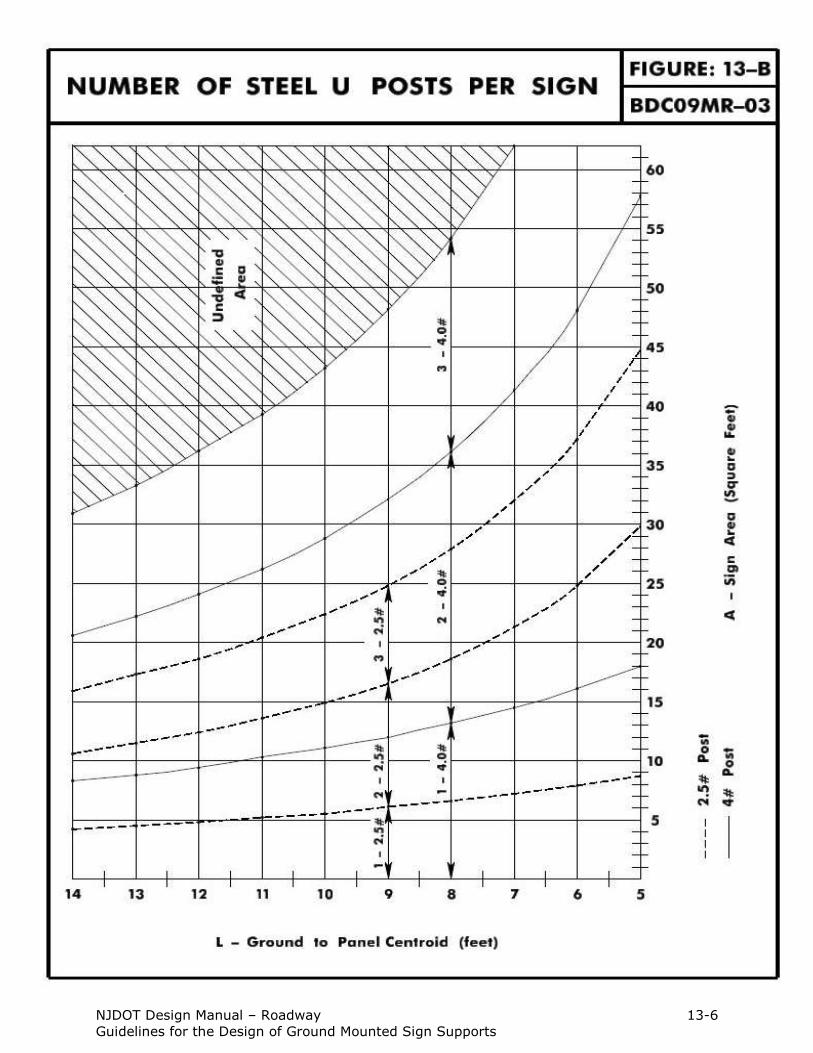
Step 4 Determine the size and quantity of posts per sign from Figure 13-B for "A" up to 50 S.F. and "L" from 7 ft. to 15 ft.
NOTE 1: When the plotted values of "A" and "L" on Figure 13-B indicate an undefined section of the chart, then an alternate design for large highway
signs must be initiated (see Section 13-03, “Large Highway Signs”).
NOTE 2:
When there is an option of using either a 2.5 lb./ft. post or a 4.0 lb./ft. post, the following applies:
a. The maximum sign width (W) for single post installations shall be 2.5 ft.
b. If the number of posts selected are the same, the 2.5 lb./ft. post should be used.
c. When the number of 2.5 lbs./ft. posts selected are greater than the number of 4 lbs./ft. posts, the 4 lbs./ft. posts should be used.
Example: A = 20 S.F.
L = 10 ft.
Roadside Slope = 10H:1V
From Figure 13-B, the number of posts that may be selected are:
three – 2.5 lbs./ft. posts or,
two – 4.0 lbs./ft. posts
Therefore, use two – 4.0 lbs./ft. posts.
Step 5 After completing Steps 1 through 4 for each sign, determine the post length(s) (P) and enter all the data onto the Steel “U” Post Sign Support
Data Table of the Standard Roadway Construction Details CD-612-6 for that project.
The following is an example of a post selection for a non-standard sign:
Highway Type - Freeway
Sign No. GA - 4
Size: 10 ft. x 4 ft.
Roadside Slope < 10H:1V
From the information provided:
Area (A) = 40 S.F.
Horizontal offset (X1) = 6 ft. (min.)
Vertical clearance = 7 ft. (min.)
Ground line to centroid (L) = 9 ft.
BDC09MR-03
NJDOT Design Manual – Roadway 13-4
Guidelines for the Design of Ground Mounted Sign Supports
From Figure 13-B:
Use three – 4 lbs./ft. posts
Distance between posts = W/3 = 40 inches (see Figure 13-A)
Post Length (P) = 7 + 4 = 11 ft.
Finally, enter the data onto the Steel “U” Post Sign Support Data Table in
the Standard Roadway Construction Details CD-612-6.
13.3 Large Highway Signs
Large GA highway signs are defined as those with a panel area equal to or greater
than 50 square feet. When this category of sign is used, the design guidelines for the support shall be “Breakaway Sign Support”. Details for breakaway sign
supports are contained in the NJDOT Standard Roadway Construction Details (CD- 612-7 through CD-612-10).
New sign supports for large GA highway signs shall be breakaway including sign
supports that are installed behind roadside barriers used to shield other roadside obstructions. When a breakaway sign support is placed behind guide rail, the
support should be a minimum of 4 ft. from the back of rail to the face of the sign post. When a breakaway sign support is placed behind barrier curb, the support shall be a minimum of 1.5 ft. from the back of barrier curb to the face of the sign
post. In no case shall the leading edge of the sign panel project beyond the face of a roadside barrier.
Existing tubular aluminum GA breakaway signs that have been impacted should be replaced in-kind unless the damage is severe enough to require new footings, signs and/or posts. Existing large permanent GA signs, Specific Service signs (Logo
signs) and Tourist-Oriented signs on wooden posts should be replaced with the breakaway sign system discussed below. All new large Specific Service signs (Logo
signs) and Tourist-Oriented signs shall be installed with the breakaway supports discussed below.
NJDOT Design Manual – Roadway 13-5
Guidelines for the Design of Ground Mounted Sign Supports
NJDOT Design Manual – Roadway 13-6
Guidelines for the Design of Ground Mounted Sign Supports
BDC09MR-03
NJDOT Design Manual – Roadway 13-7
Guidelines for the Design of Ground Mounted Sign Supports
13.3.1 Breakaway Sign Supports
The following subsection provides a step-by-step guide to the design of breakaway sign supports.
13.3.1.1 Breakaway Sign Support
The following is a step-by-step guide to the design of breakaway sign supports:
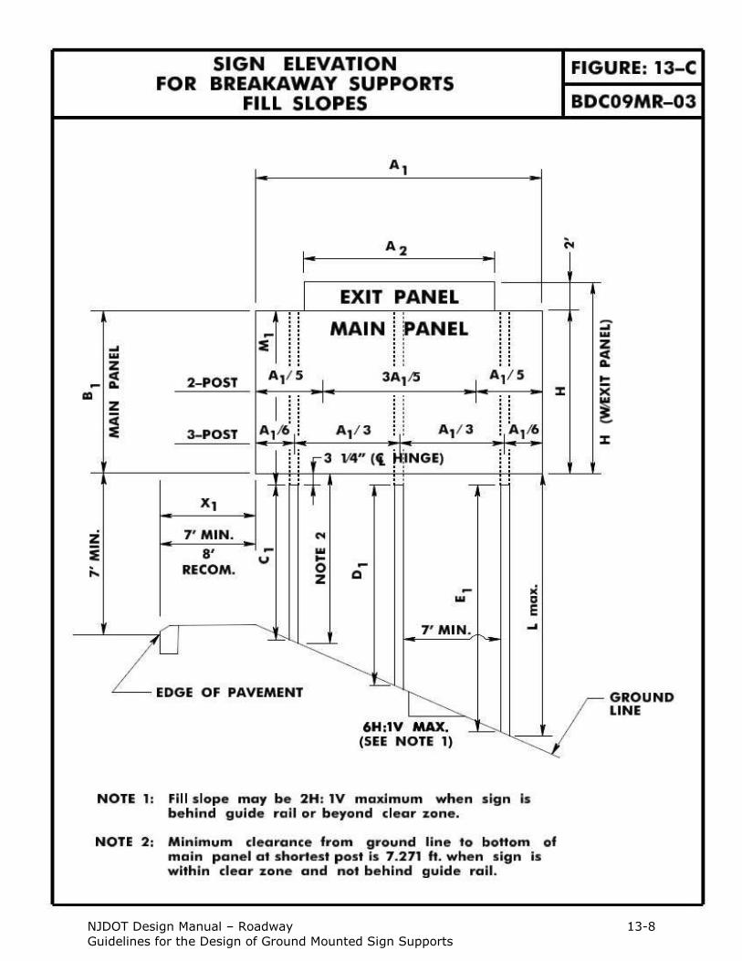
Step 1 Once provided with the size of the main panel, determine the horizontal offset, X1, from the edge of pavement to the edge of panel. Recommended offset = 8 ft., minimum offset = 7 ft.
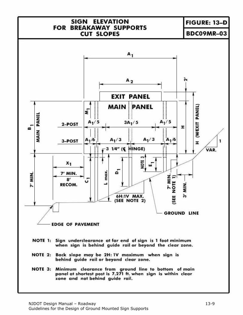
Step 2 Determine the elevation from the edge of pavement to the bottom of the main panel. Minimum mounting height = 7 ft. (see Figure 13-C and 13-D).
a. For fill sections, when the sign is within the clear zone and not behind guide rail, a 6H:1V slope or flatter must be held for a minimum of 3 feet beyond the berm side of the main panel and 100 feet ahead of the sign
face (see Standard Roadway Construction Detail CD-612-7).
b. For cut sections, when the sign is within the clear zone and not behind
guide rail, hold the far edge bottom corner of the main panel at the 7.271 ft. minimum and provide a 6H:1V slope or flatter for a minimum of 3 ft. beyond the berm side of the main panel and 100 ft. ahead of the
sign face (see Figure 13-D and Standard Roadway Construction Detail CD-612-7). If the sign is beyond the clear zone or behind guide rail, the
clearance at the far edge bottom corner of the main panel may be 1 foot.
c. When the sign is beyond the clear zone or behind guide rail, the 6H:1V
slope or flatter grading requirement may be eliminated.
Step 3 Determine the number of posts required for the specified panel based on a
minimum spacing between posts of 7 ft. (see Figure 13-C).
NOTE: For main panel widths less than 24 ft., a three post support system shall
not be used. Since the spacing for a three post support system requires A1/3 between sign posts, only a 24 ft. width or greater would provide the 7
ft. minimum required spacing between posts. Therefore, either a two post or three post support system could be utilized for widths greater than or equal to 24 ft.
Step 4 Determine the distances from ground line to bottom of main panel, L, for each post.
NOTE: The minimum distance from ground line to the bottom of the main panel
shall be 7.271 ft.
Step 5 Determine the required values of Lmax, H, and A1 where:
Lmax = Maximum post length to bottom of main panel (feet)
H = Main panel height + Exit panel height (feet)
A1 = Main panel width (feet)
NJDOT Design Manual – Roadway 13-8
Guidelines for the Design of Ground Mounted Sign Supports
NJDOT Design Manual – Roadway 13-9
Guidelines for the Design of Ground Mounted Sign Supports
BDC09MR-03
NJDOT Design Manual – Roadway 13-10
Guidelines for the Design of Ground Mounted Sign Supports
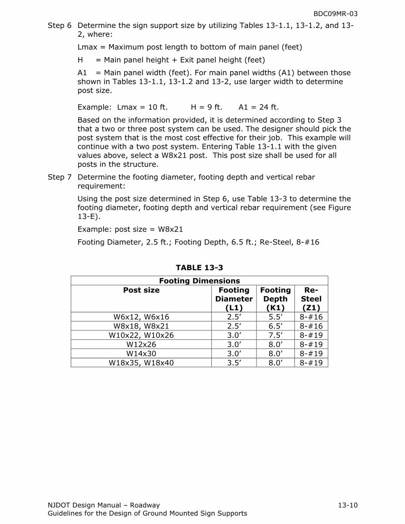
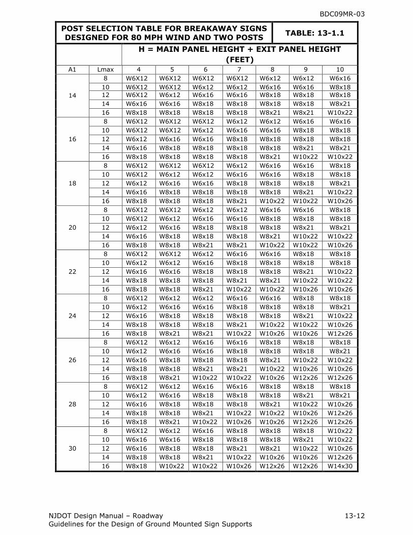
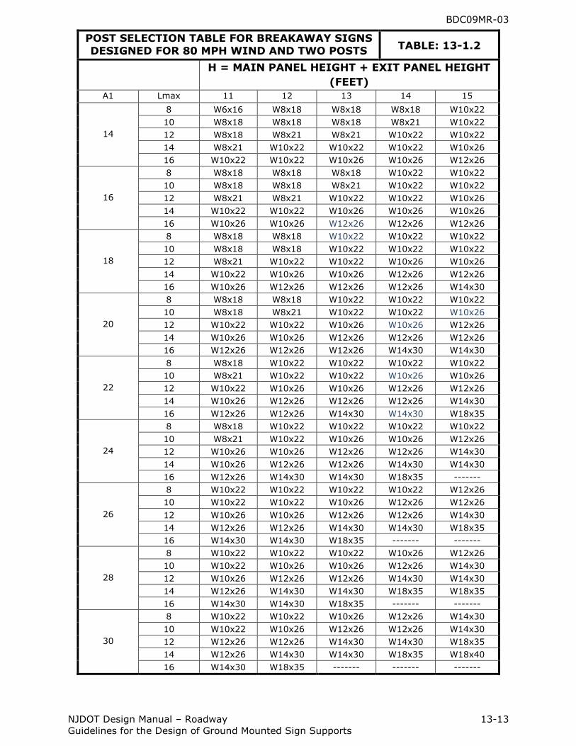
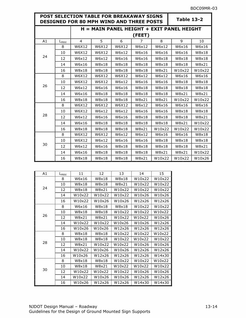
Step 6 Determine the sign support size by utilizing Tables 13-1.1, 13-1.2, and 13-2, where:
Lmax = Maximum post length to bottom of main panel (feet)
H = Main panel height + Exit panel height (feet)
A1 = Main panel width (feet). For main panel widths (A1) between those
shown in Tables 13-1.1, 13-1.2 and 13-2, use larger width to determine post size.
Example: Lmax = 10 ft. H = 9 ft. A1 = 24 ft.
Based on the information provided, it is determined according to Step 3 that a two or three post system can be used. The designer should pick the
post system that is the most cost effective for their job. This example will continue with a two post system. Entering Table 13-1.1 with the given values above, select a W8x21 post. This post size shall be used for all
posts in the structure.
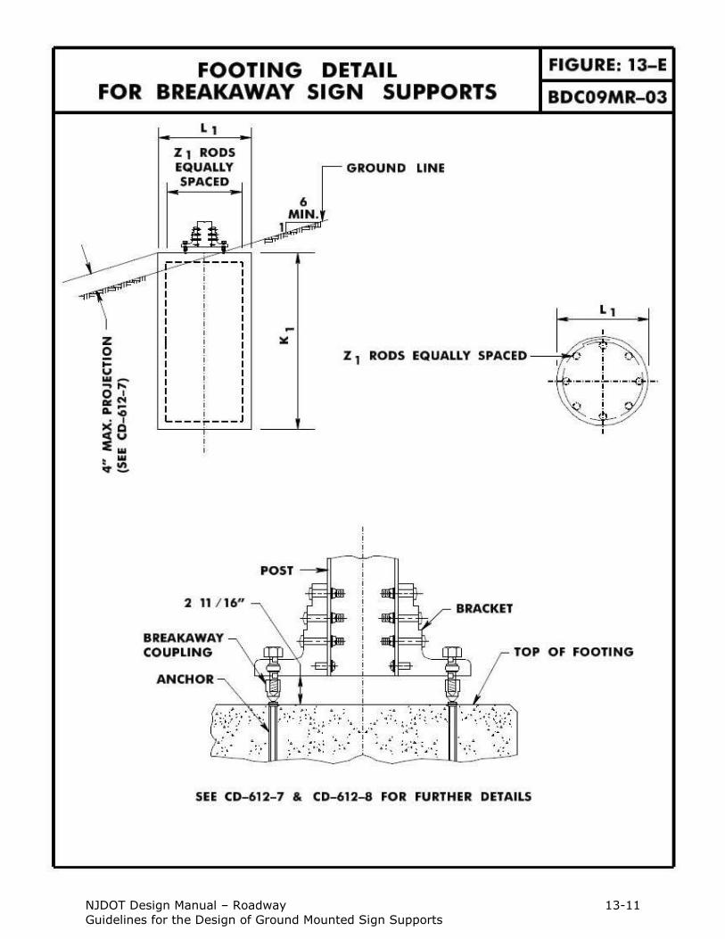
Step 7 Determine the footing diameter, footing depth and vertical rebar
requirement:
Using the post size determined in Step 6, use Table 13-3 to determine the footing diameter, footing depth and vertical rebar requirement (see Figure
13-E).
Example: post size = W8x21
Footing Diameter, 2.5 ft.; Footing Depth, 6.5 ft.; Re-Steel, 8-#16
TABLE 13-3
Footing Dimensions
Post size Footing Diameter
(L1)
Footing Depth (K1)
Re-Steel (Z1)
W6x12, W6x16 2.5‟ 5.5‟ 8-#16
W8x18, W8x21 2.5‟ 6.5‟ 8-#16
W10x22, W10x26 3.0‟ 7.5‟ 8-#19
W12x26 3.0‟ 8.0‟ 8-#19
W14x30 3.0‟ 8.0‟ 8-#19
W18x35, W18x40 3.5‟ 8.0‟ 8-#19
NJDOT Design Manual – Roadway 13-11
Guidelines for the Design of Ground Mounted Sign Supports
BDC09MR-03
NJDOT Design Manual – Roadway 13-12
Guidelines for the Design of Ground Mounted Sign Supports
POST SELECTION TABLE FOR BREAKAWAY SIGNS DESIGNED FOR 80 MPH WIND AND TWO POSTS
TABLE: 13-1.1
H = MAIN PANEL HEIGHT + EXIT PANEL HEIGHT
(FEET)
A1 Lmax 4 5 6 7 8 9 10
14
8 W6X12 W6X12 W6X12 W6X12 W6x12 W6x12 W6x16
10 W6X12 W6X12 W6x12 W6x12 W6x16 W6x16 W8x18
12 W6X12 W6x12 W6x16 W6x16 W8x18 W8x18 W8x18
14 W6x16 W6x16 W8x18 W8x18 W8x18 W8x18 W8x21
16 W8x18 W8x18 W8x18 W8x18 W8x21 W8x21 W10x22
16
8 W6X12 W6X12 W6X12 W6x12 W6x12 W6x16 W6x16
10 W6X12 W6X12 W6x12 W6x16 W6x16 W8x18 W8x18
12 W6x12 W6x16 W6x16 W8x18 W8x18 W8x18 W8x18
14 W6x16 W8x18 W8x18 W8x18 W8x18 W8x21 W8x21
16 W8x18 W8x18 W8x18 W8x18 W8x21 W10x22 W10x22
18
8 W6X12 W6X12 W6X12 W6x12 W6x16 W6x16 W8x18
10 W6X12 W6x12 W6x12 W6x16 W6x16 W8x18 W8x18
12 W6x12 W6x16 W6x16 W8x18 W8x18 W8x18 W8x21
14 W6x16 W8x18 W8x18 W8x18 W8x18 W8x21 W10x22
16 W8x18 W8x18 W8x18 W8x21 W10x22 W10x22 W10x26
20
8 W6X12 W6X12 W6x12 W6x12 W6x16 W6x16 W8x18
10 W6X12 W6x12 W6x16 W6x16 W8x18 W8x18 W8x18
12 W6x12 W6x16 W8x18 W8x18 W8x18 W8x21 W8x21
14 W6x16 W8x18 W8x18 W8x18 W8x21 W10x22 W10x22
16 W8x18 W8x18 W8x21 W8x21 W10x22 W10x22 W10x26
22
8 W6X12 W6X12 W6x12 W6x16 W6x16 W8x18 W8x18
10 W6x12 W6x12 W6x16 W8x18 W8x18 W8x18 W8x18
12 W6x16 W6x16 W8x18 W8x18 W8x18 W8x21 W10x22
14 W8x18 W8x18 W8x18 W8x21 W8x21 W10x22 W10x22
16 W8x18 W8x18 W8x21 W10x22 W10x22 W10x26 W10x26
24
8 W6X12 W6x12 W6x12 W6x16 W6x16 W8x18 W8x18
10 W6x12 W6x16 W6x16 W8x18 W8x18 W8x18 W8x21
12 W6x16 W8x18 W8x18 W8x18 W8x18 W8x21 W10x22
14 W8x18 W8x18 W8x18 W8x21 W10x22 W10x22 W10x26
16 W8x18 W8x21 W8x21 W10x22 W10x26 W10x26 W12x26
26
8 W6X12 W6x12 W6x16 W6x16 W8x18 W8x18 W8x18
10 W6x12 W6x16 W6x16 W8x18 W8x18 W8x18 W8x21
12 W6x16 W8x18 W8x18 W8x18 W8x21 W10x22 W10x22
14 W8x18 W8x18 W8x21 W8x21 W10x22 W10x26 W10x26
16 W8x18 W8x21 W10x22 W10x22 W10x26 W12x26 W12x26
28
8 W6X12 W6x12 W6x16 W6x16 W8x18 W8x18 W8x18
10 W6x12 W6x16 W8x18 W8x18 W8x18 W8x21 W8x21
12 W6x16 W8x18 W8x18 W8x18 W8x21 W10x22 W10x26
14 W8x18 W8x18 W8x21 W10x22 W10x22 W10x26 W12x26
16 W8x18 W8x21 W10x22 W10x26 W10x26 W12x26 W12x26
30
8 W6X12 W6x12 W6x16 W8x18 W8x18 W8x18 W10x22
10 W6x16 W6x16 W8x18 W8x18 W8x18 W8x21 W10x22
12 W6x16 W8x18 W8x18 W8x21 W8x21 W10x22 W10x26
14 W8x18 W8x18 W8x21 W10x22 W10x26 W10x26 W12x26
16 W8x18 W10x22 W10x22 W10x26 W12x26 W12x26 W14x30
BDC09MR-03
NJDOT Design Manual – Roadway 13-13
Guidelines for the Design of Ground Mounted Sign Supports
POST SELECTION TABLE FOR BREAKAWAY SIGNS
DESIGNED FOR 80 MPH WIND AND TWO POSTS TABLE: 13-1.2
H = MAIN PANEL HEIGHT + EXIT PANEL HEIGHT
(FEET)
A1 Lmax 11 12 13 14 15
14
8 W6x16 W8x18 W8x18 W8x18 W10x22
10 W8x18 W8x18 W8x18 W8x21 W10x22
12 W8x18 W8x21 W8x21 W10x22 W10x22
14 W8x21 W10x22 W10x22 W10x22 W10x26
16 W10x22 W10x22 W10x26 W10x26 W12x26
16
8 W8x18 W8x18 W8x18 W10x22 W10x22
10 W8x18 W8x18 W8x21 W10x22 W10x22
12 W8x21 W8x21 W10x22 W10x22 W10x26
14 W10x22 W10x22 W10x26 W10x26 W10x26
16 W10x26 W10x26 W12x26 W12x26 W12x26
18
8 W8x18 W8x18 W10x22 W10x22 W10x22
10 W8x18 W8x18 W10x22 W10x22 W10x22
12 W8x21 W10x22 W10x22 W10x26 W10x26
14 W10x22 W10x26 W10x26 W12x26 W12x26
16 W10x26 W12x26 W12x26 W12x26 W14x30
20
8 W8x18 W8x18 W10x22 W10x22 W10x22
10 W8x18 W8x21 W10x22 W10x22 W10x26
12 W10x22 W10x22 W10x26 W10x26 W12x26
14 W10x26 W10x26 W12x26 W12x26 W12x26
16 W12x26 W12x26 W12x26 W14x30 W14x30
22
8 W8x18 W10x22 W10x22 W10x22 W10x22
10 W8x21 W10x22 W10x22 W10x26 W10x26
12 W10x22 W10x26 W10x26 W12x26 W12x26
14 W10x26 W12x26 W12x26 W12x26 W14x30
16 W12x26 W12x26 W14x30 W14x30 W18x35
24
8 W8x18 W10x22 W10x22 W10x22 W10x22
10 W8x21 W10x22 W10x26 W10x26 W12x26
12 W10x26 W10x26 W12x26 W12x26 W14x30
14 W10x26 W12x26 W12x26 W14x30 W14x30
16 W12x26 W14x30 W14x30 W18x35 -------
26
8 W10x22 W10x22 W10x22 W10x22 W12x26
10 W10x22 W10x22 W10x26 W12x26 W12x26
12 W10x26 W10x26 W12x26 W12x26 W14x30
14 W12x26 W12x26 W14x30 W14x30 W18x35
16 W14x30 W14x30 W18x35 ------- -------
28
8 W10x22 W10x22 W10x22 W10x26 W12x26
10 W10x22 W10x26 W10x26 W12x26 W14x30
12 W10x26 W12x26 W12x26 W14x30 W14x30
14 W12x26 W14x30 W14x30 W18x35 W18x35
16 W14x30 W14x30 W18x35 ------- -------
30
8 W10x22 W10x22 W10x26 W12x26 W14x30
10 W10x22 W10x26 W12x26 W12x26 W14x30
12 W12x26 W12x26 W14x30 W14x30 W18x35
14 W12x26 W14x30 W14x30 W18x35 W18x40
16 W14x30 W18x35 ------- ------- -------
BDC09MR-03
NJDOT Design Manual – Roadway 13-14
Guidelines for the Design of Ground Mounted Sign Supports
POST SELECTION TABLE FOR BREAKAWAY SIGNS
DESIGNED FOR 80 MPH WIND AND THREE POSTS Table 13-2
H = MAIN PANEL HEIGHT + EXIT PANEL HEIGHT
(FEET)
A1 LMAX 4 5 6 7 8 9 10
24
8 W6X12 W6X12 W6X12 W6x12 W6x12 W6x16 W6x16
10 W6X12 W6X12 W6x12 W6x16 W6x16 W6x16 W8x18
12 W6x12 W6x12 W6x16 W6x16 W8x18 W8x18 W8x18
14 W6x16 W8x18 W8x18 W8x18 W8x18 W8x18 W8x21
16 W8x18 W8x18 W8x18 W8x18 W8x21 W10x22 W10x22
26
8 W6X12 W6X12 W6X12 W6x12 W6x12 W6x16 W6x16
10 W6X12 W6X12 W6x12 W6x16 W6x16 W8x18 W8x18
12 W6x12 W6x16 W6x16 W8x18 W8x18 W8x18 W8x18
14 W6x16 W8x18 W8x18 W8x18 W8x18 W8x21 W8x21
16 W8x18 W8x18 W8x18 W8x21 W8x21 W10x22 W10x22
28
8 W6X12 W6X12 W6X12 W6x12 W6x16 W6x16 W6x16
10 W6X12 W6x12 W6x12 W6x16 W6x16 W8x18 W8x18
12 W6x12 W6x16 W6x16 W8x18 W8x18 W8x18 W8x21
14 W6x16 W8x18 W8x18 W8x18 W8x18 W8x21 W10x22
16 W8x18 W8x18 W8x18 W8x21 W10x22 W10x22 W10x22
30
8 W6X12 W6X12 W6x12 W6x12 W6x16 W6x16 W8x18
10 W6X12 W6x12 W6x16 W6x16 W8x18 W8x18 W8x18
12 W6x12 W6x16 W8x18 W8x18 W8x18 W8x18 W8x21
14 W6x16 W8x18 W8x18 W8x18 W8x21 W8x21 W10x22
16 W8x18 W8x18 W8x18 W8x21 W10x22 W10x22 W10x26
A1 LMAX 11 12 13 14 15
24
8 W6x16 W8x18 W8x18 W10x22 W10x22
10 W8x18 W8x18 W8x21 W10x22 W10x22
12 W8x18 W8x21 W10x22 W10x22 W10x22
14 W10x22 W10x22 W10x22 W10x26 W10x26
16 W10x22 W10x26 W10x26 W12x26 W12x26
26
8 W6x16 W8x18 W8x18 W10x22 W10x22
10 W8x18 W8x18 W10x22 W10x22 W10x22
12 W8x21 W8x21 W10x22 W10x22 W10x26
14 W10x22 W10x22 W10x26 W10x26 W12x26
16 W10x26 W10x26 W12x26 W12x26 W12x26
28
8 W8x18 W8x18 W10x22 W10x22 W10x22
10 W8x18 W8x18 W10x22 W10x22 W10x22
12 W8x21 W10x22 W10x22 W10x26 W10x26
14 W10x22 W10x26 W10x26 W12x26 W12x26
16 W10x26 W12x26 W12x26 W12x26 W14x30
30
8 W8x18 W8x18 W10x22 W10x22 W10x22
10 W8x18 W8x21 W10x22 W10x22 W10x22
12 W10x22 W10x22 W10x22 W10x26 W10x26
14 W10x22 W10x26 W10x26 W12x26 W12x26
16 W10x26 W12x26 W12x26 W14x30 W14x30
BDC09MR-03
NJDOT Design Manual – Roadway 13-15
Guidelines for the Design of Ground Mounted Sign Supports
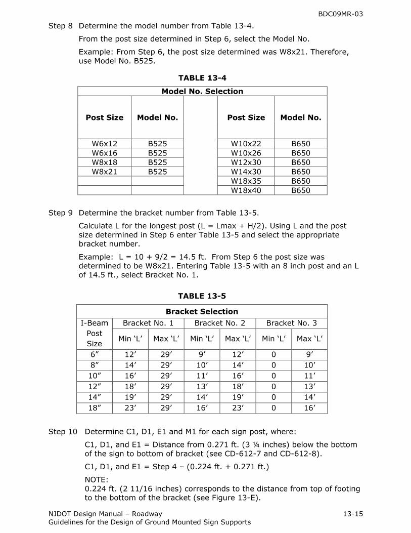
Step 8 Determine the model number from Table 13-4.
From the post size determined in Step 6, select the Model No.
Example: From Step 6, the post size determined was W8x21. Therefore,
use Model No. B525.
TABLE 13-4
Model No. Selection
Post Size Model No.
Post Size Model No.
W6x12 B525 W10x22 B650
W6x16 B525 W10x26 B650
W8x18 B525 W12x30 B650
W8x21 B525 W14x30 B650
W18x35 B650
W18x40 B650
Step 9 Determine the bracket number from Table 13-5.
Calculate L for the longest post (L = Lmax + H/2). Using L and the post
size determined in Step 6 enter Table 13-5 and select the appropriate bracket number.
Example: L = 10 + 9/2 = 14.5 ft. From Step 6 the post size was determined to be W8x21. Entering Table 13-5 with an 8 inch post and an L of 14.5 ft., select Bracket No. 1.
TABLE 13-5
Bracket Selection
I-Beam
Post
Size
Bracket No. 1 Bracket No. 2 Bracket No. 3
Min „L‟ Max „L‟ Min „L‟ Max „L‟ Min „L‟ Max „L‟
6” 12‟ 29‟ 9‟ 12‟ 0 9‟
8” 14‟ 29‟ 10‟ 14‟ 0 10‟
10” 16‟ 29‟ 11‟ 16‟ 0 11‟
12” 18‟ 29‟ 13‟ 18‟ 0 13‟
14” 19‟ 29‟ 14‟ 19‟ 0 14‟
18” 23‟ 29‟ 16‟ 23‟ 0 16‟
Step 10 Determine C1, D1, E1 and M1 for each sign post, where:
C1, D1, and E1 = Distance from 0.271 ft. (3 ¼ inches) below the bottom
of the sign to bottom of bracket (see CD-612-7 and CD-612-8).
C1, D1, and E1 = Step 4 – (0.224 ft. + 0.271 ft.)
NOTE:
0.224 ft. (2 11/16 inches) corresponds to the distance from top of footing to the bottom of the bracket (see Figure 13-E).
BDC09MR-03
NJDOT Design Manual – Roadway 13-16
Guidelines for the Design of Ground Mounted Sign Supports
M1 = Distance from the top of sign to 0.271 ft. (3 ¼ inches) below the bottom of the sign (B1+0.271).
Step 11 Determine F1, G1, and H1 for each post, see Standard Roadway
Construction Details CD-612-7. Values above reference line are positive, values below reference line are negative.
Step 12 Enter all the data onto the Breakaway Support Data Table in the Standard Roadway Construction Details CD-612-10.
13.3.2 Nonvegetative Surface Under Overhead Signs and Large Ground
Mounted Signs
In order to reduce soil erosion and highway maintenance costs associated with
spraying or trimming vegetation underneath signs, nonvegetative surfaces should be applied around the foundation of overhead signs and underneath large ground mounted signs as follows:
A. Sign types – Conditions warranting use of nonvegetative surfaces
1. Overhead Signs
2. Sign Bridge- All cases
3. Sign Cantilever – All cases
4. Large Ground Mounted Signs
5. Breakaway Sign Supports – Mowable areas
6. Nonbreakaway Sign Support – Mowable areas
This surface treatment is not to be used at breakaway steel “U” post sign support locations.
The nonvegetative surfaces shall be constructed as shown in Standard Roadway
Construction Detail CD-608-1.