Section 12 engine starting and ignition
31
© International Aero Engines Inc 2000 Engine Starting and Engine Starting and Ignition Ignition System comprises: Pneumatic Starter Motor. Starter Air Control Valve. Dual Ignition System. Pneumatic Ducting. Start Control Panel on Flight Deck.
-
Upload
ricardo-ccoyure-tito -
Category
Education
-
view
193 -
download
3
Transcript of Section 12 engine starting and ignition

© International Aero Engines Inc 2000
Engine Starting and Ignition Engine Starting and Ignition
System comprises:
Pneumatic Starter Motor. Starter Air Control Valve. Dual Ignition System. Pneumatic Ducting. Start Control Panel on Flight Deck.

© International Aero Engines Inc 2000
Engine Starting and Ignition Engine Starting and Ignition
Start Panel provides the following functions:
Automatic starting. Manual Starting. Dry Cranking. Wet Cranking. Continuous Ignition.

© International Aero Engines Inc 2000
Pneumatic supplies for the starter can be
provided by:
Auxiliary Power Unit (APU). Ground Supply. The Other Engine (if already started).
Engine Starting and IgnitionEngine Starting and Ignition

© International Aero Engines Inc 2000
During Auto Start, the critical parameters are
monitored by the EEC to identify a faulty start:
Identified as: ‘Hot’ Start. ‘Hung’ Start. No ‘light up’. Pressure Raising and Shut-Off Valve failure. No N1 Rotation
Engine Starting and IgnitionEngine Starting and Ignition
© International Aero Engines Inc 2000
The EEC will carry out an automatic engine shut down (start abort)
Provide a motoring cycle to clear fuel vapours and to cool the engine,
Engine Starting and IgnitionEngine Starting and Ignition
© International Aero Engines Inc 2000
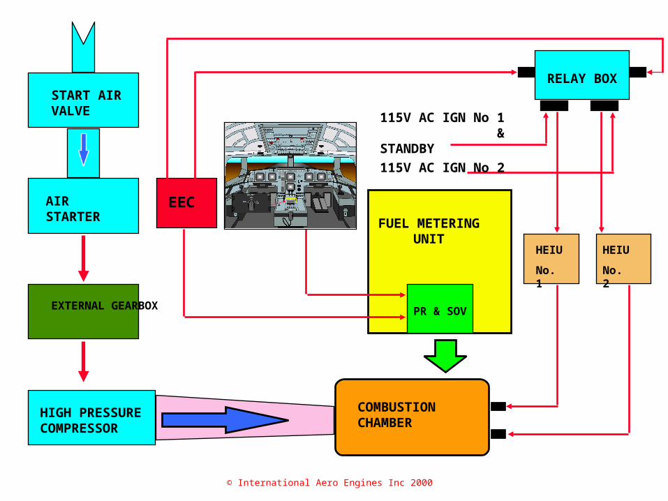
EEC FLIGHT DECK FUEL METERING
UNIT
PR & SOV
COMBUSTION CHAMBER
HIGH PRESSURE COMPRESSOR
EXTERNAL GEARBOX
AIR STARTER
START AIR VALVE
RELAY BOX
HEIU
No. 1
HEIU
No. 2
115V AC IGN No 1 & STANDBY
115V AC IGN No 2
COMBUSTION CHAMBER
© International Aero Engines Inc 2000
© International Aero Engines Inc 2000
Engine Starting and Ignition Engine Starting and Ignition
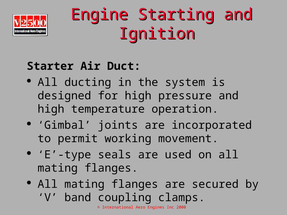
Starter Air Duct: All ducting in the system is designed for high
pressure and high temperature operation. ‘Gimbal’ joints are incorporated to permit
working movement. ‘E’-type seals are used on all mating flanges. All mating flanges are secured by ‘V’ band
coupling clamps.
© International Aero Engines Inc 2000
Starter Motor:
Mounted on the forward face of the external gearbox.
Provides the drive to rotate the H.P. compressor to a speed at which engine ‘light-up’ can occur.
The starter motor gears and bearings are lubricated by an integral lubrication system.
Engine Starting and IgnitionEngine Starting and Ignition

© International Aero Engines Inc 2000
Engine Starting and Ignition Engine Starting and Ignition
Starter Motor: Attached to the external gearbox by quick
attach/detach adapter ring. A quick detach ‘V’ clamp fixes the starter to the ring Servicing features include:
Oil filler/level plug
Drain plug and magnetic chip detector
Oil level sight glass
Oil filler/level plug.
Built in drain plug and magnetic chip detector.
Oil level sight glass

© International Aero Engines Inc 2000
Starter Installation Coupling
Starter AdapterEngine Starter
Gearbox
© International Aero Engines Inc 2000
Engine Starting and Ignition Engine Starting and Ignition
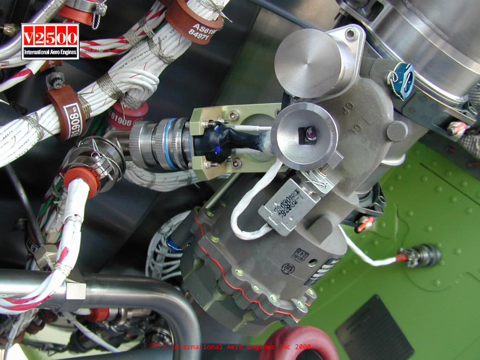
Starter Air Control Valve: Pneumatically operated, electrically controlled.
Location: Lower right hand side of the Fan Case. ‘Butterfly’ type valve housed in a cylindrical valve
body, with:
In-line flanged end connectors.
An Actuator.
Solenoid valve.
Pressure controller.
© International Aero Engines Inc 2000
Starter Air Control Valve:
Manual Operation: The valve can be manually opened by using a
0.375 inch square drive. Access panel in the right hand fan cowl. Valve position indicator on the valve body. Feedback to the EEC of valve position from a
microswitch.
Engine Starting and IgnitionEngine Starting and Ignition

© International Aero Engines Inc 2000© International Aero Engines Inc 2000
© International Aero Engines Inc 2000© International Aero Engines Inc 2000

© International Aero Engines Inc 2000© International Aero Engines Inc 2000

© International Aero Engines Inc 2000
Engine Starting and Ignition Engine Starting and Ignition
Starter Air Control Valve:
Valve Opening: Solenoid valve opens when engine start signal
received. Simultaneously closes vent port. Starter delivery pressure causes actuator piston
to move. As piston is mechanically connected to the
starter valve, the starter air valve opens.

© International Aero Engines Inc 2000
Starter Air Control Valve:
Valve closing: When the engine speed reaches approximately
6000 rpm (43%) N2, the solenoid valve de-energises.
Ball valve closes and the air pressure acting on the piston is vented to atmosphere.
Air pressure and spring pressure acting on the smaller piston, cause it to return to the closed position this closes the butterfly valve.
Engine Starting and IgnitionEngine Starting and Ignition
© International Aero Engines Inc 2000
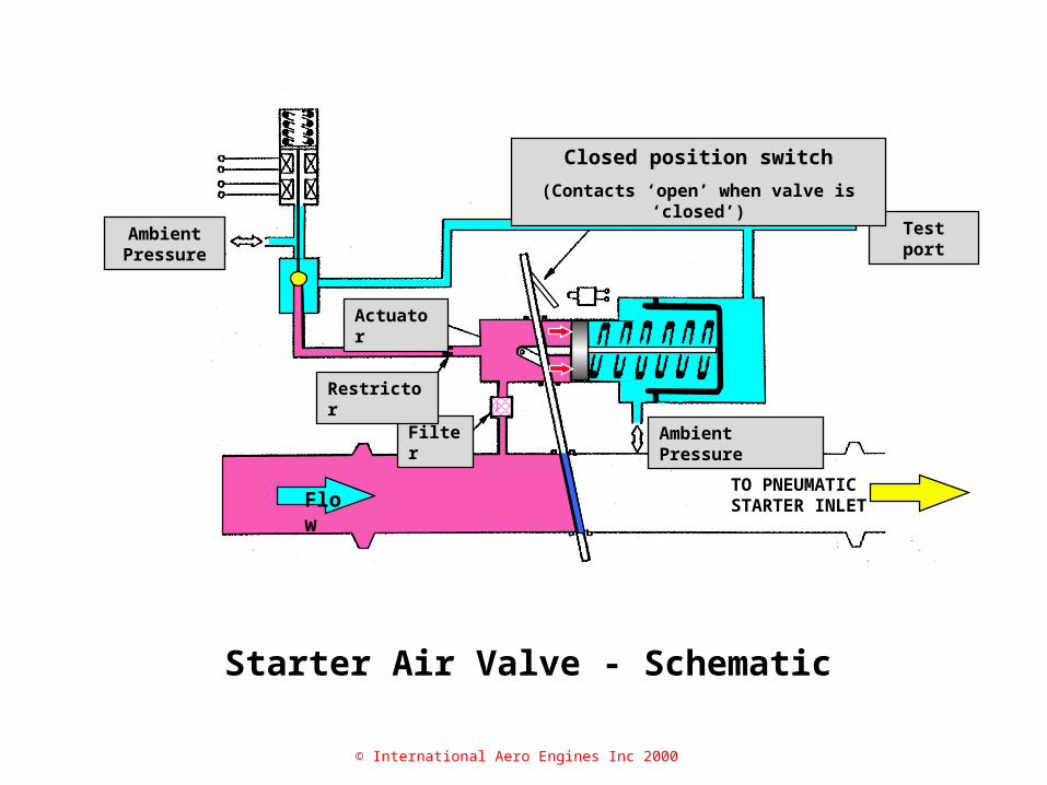
Starter Air Valve - Schematic
TO PNEUMATIC STARTER INLETFlow
Test port
Closed position switch
(Contacts ‘open’ when valve is ‘closed’)
Ambient PressureFilter
Restrictor
Actuator
Ambient Pressure
© International Aero Engines Inc 2000

© International Aero Engines Inc 2000
Starter Air Valve - Schematic
FlowTO PNEUMATIC STARTER INLET
Test port
Closed position switch
(Contacts ‘open’ when valve is ‘closed’)
Ambient PressureFilter
Restrictor
Actuator
Ambient Pressure

© International Aero Engines Inc 2000
Starter Air Valve - Schematic
FlowTO PNEUMATIC STARTER INLET Flow
Ambient Pressure
Restrictor
Closed position switch
(Contacts ‘open’ when valve is ‘closed’)
Actuator
Filter Ambient Pressure
Test port

© International Aero Engines Inc 2000
Starter Air Valve - Schematic
TO PNEUMATIC STARTER INLETFlow
Test port
Closed position switch
(Contacts ‘open’ when valve is ‘closed’)
Ambient PressureFilter
Restrictor
Actuator
Ambient Pressure

© International Aero Engines Inc 2000
Ignition:
System comprises of the following:
2 ignition exciter units. 2 igniter plugs - located in the combustion
chamber adjacent to # 7 and # 8 fuel spray nozzles.
2 ‘air cooled’ (H.T.) ignition connector leads.
Engine Starting and IgnitionEngine Starting and Ignition

© International Aero Engines Inc 2000
© International Aero Engines Inc 2000© International Aero Engines Inc 2000

© International Aero Engines Inc 2000
Ignition:
Dual ignition is automatically selected for:
All in-flight starts. Manual start attempts. Continuous ignition.
Engine Starting and IgnitionEngine Starting and Ignition

© International Aero Engines Inc 2000
Ignition:
Continuous ignition automatically selected if: The engine anti-ice system is ‘on’. Aircraft flaps are extended for: Take-off. Approach. Landing. Continuous ignition may also be selected
manually.
Engine Starting and IgnitionEngine Starting and Ignition
© International Aero Engines Inc 2000
Ignition Test:
the operation of the ignition system can be checked on the ground, with the engine static. Using the maintenance mode of the Centralised Fault Display System (CFDS)
Engine Starting and IgnitionEngine Starting and Ignition

© International Aero Engines Inc 2000
Multi-purpose Control Display Unit
FADEC Ground Power
Engine Start Panel© International Aero Engines Inc 2000

© International Aero Engines Inc 2000
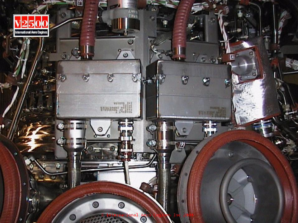
Ignition Relay Box:
Ignition system uses 115V AC supplied by the ‘Normal’ and ‘Essential’ bus bars to the Relay Box.
Controlled by signals from the EEC. Relay Box includes the relay that controls the
115V AC supplies for the P2/T2 probe heating elements.
Engine Starting and IgnitionEngine Starting and Ignition

© International Aero Engines Inc 2000Relay Box
© International Aero Engines Inc 2000

© International Aero Engines Inc 2000© International Aero Engines Inc 2000