SECTION 11332A MECHANICAL BAR SCREENS PART 1 … · ANSI B18.6.2 - (1972) ... or ASME Boiler and...
642
City Project No. UY-16/01-20 Invitation for Bids #PW 16-28 City of Sunnyvale Primary Treatment Facility Package 2 Technical Specifications December 2016 MECHANICAL BAR SCREENS 11332A-1 pw://Carollo/Documents/Client/CA/Sunnyvale/9265A10/Specifications/Package 02/11332A (FS) SECTION 11332A MECHANICAL BAR SCREENS PART 1 GENERAL 1.01 SUMMARY A. Section includes: Mechanically cleaned bar screens: 1. Equipment Tag Numbers: a. Bar Screen No. 1 - BAR-211.111. b. Bar Screen No. 2 - BAR-211.112. c. Bar Screen No. 3 - BAR-211.113. d. Bar Screen No. 4 - BAR-211.114. B. Related sections: 1. The Contract Documents are complementary; what is called for by one is as binding as if called for by all. 2. It is the Contractor’s responsibility for scheduling and coordinating the Work of subcontractors, suppliers, and other individuals or entities performing or furnishing any of Contractor’s Work. 3. The following Sections are related to the Work described in this Section. This list of Related Sections is provided for convenience only and is not intended to excuse or otherwise diminish the duty of the Contractor to see that the completed Work complies accurately with the Contract Documents: a. Section 01010 - Summary of Work. b. Section 01340 - Shop Drawings, Product Data and Samples. c. Section 01610 - Project Design Criteria. d. Section 01612 - Seismic Design Criteria. e. Section 01614 - Wind Design Criteria. f. Section 01730 - Operation and Maintenance Data. g. Section 01756 - Testing, Training, and Facility Start-Up. h. Section 05120 - Structural Steel. i. Section 05500 - Metal Fabrications. j. Section 09960 - High-Performance Coatings. k. Section 15050 - Common Work Results for Mechanical Equipment. l. Section 15120 - Piping Specialties. m. Section 15958 - Mechanical Equipment Testing. n. Section 16050 - Common Work Results for Electrical. o. Section 16134 - Boxes. p. Section 16222 - Low Voltage Motors up to 500 Horsepower. q. Section 16262 - Variable Frequency Drives 0.50 - 50 Horsepower. r. Section 17050 - Common Works Results for Process Control and Instrumentation Systems. s. Section 17100 - Control Strategies. t. Section 17101 - Specific Control Strategies. u. Section 17710 - Control Systems - Panels, Enclosures, and Panel Components.
Transcript of SECTION 11332A MECHANICAL BAR SCREENS PART 1 … · ANSI B18.6.2 - (1972) ... or ASME Boiler and...
City Project No. UY-16/01-20 Invitation for Bids #PW 16-28City of Sunnyvale Primary Treatment Facility Package 2 Technical SpecificationsDecember 2016
MECHANICAL BAR SCREENS 11332A-1 pw://Carollo/Documents/Client/CA/Sunnyvale/9265A10/Specifications/Package 02/11332A (FS)
SECTION 11332A
MECHANICAL BAR SCREENS
PART 1 GENERAL
1.01 SUMMARY
A. Section includes: Mechanically cleaned bar screens:1. Equipment Tag Numbers:
a. Bar Screen No. 1 - BAR-211.111. b. Bar Screen No. 2 - BAR-211.112.c. Bar Screen No. 3 - BAR-211.113.d. Bar Screen No. 4 - BAR-211.114.
B. Related sections:1. The Contract Documents are complementary; what is called for by one is as
binding as if called for by all.2. It is the Contractor’s responsibility for scheduling and coordinating the Work of
subcontractors, suppliers, and other individuals or entities performing or furnishing any of Contractor’s Work.
3. The following Sections are related to the Work described in this Section. This list of Related Sections is provided for convenience only and is not intended to excuse or otherwise diminish the duty of the Contractor to see that the completed Work complies accurately with the Contract Documents:a. Section 01010 - Summary of Work.b. Section 01340 - Shop Drawings, Product Data and Samples.c. Section 01610 - Project Design Criteria.d. Section 01612 - Seismic Design Criteria.e. Section 01614 - Wind Design Criteria.f. Section 01730 - Operation and Maintenance Data.g. Section 01756 - Testing, Training, and Facility Start-Up.h. Section 05120 - Structural Steel.i. Section 05500 - Metal Fabrications.j. Section 09960 - High-Performance Coatings.k. Section 15050 - Common Work Results for Mechanical Equipment. l. Section 15120 - Piping Specialties.m. Section 15958 - Mechanical Equipment Testing.n. Section 16050 - Common Work Results for Electrical.o. Section 16134 - Boxes. p. Section 16222 - Low Voltage Motors up to 500 Horsepower.q. Section 16262 - Variable Frequency Drives 0.50 - 50 Horsepower.r. Section 17050 - Common Works Results for Process Control and
Instrumentation Systems.s. Section 17100 - Control Strategies.t. Section 17101 - Specific Control Strategies. u. Section 17710 - Control Systems - Panels, Enclosures, and Panel
Components.
City Project No. UY-16/01-20 Invitation for Bids #PW 16-28City of Sunnyvale Primary Treatment Facility Package 2 Technical SpecificationsDecember 2016
MECHANICAL BAR SCREENS 11332A-2 pw://Carollo/Documents/Client/CA/Sunnyvale/9265A10/Specifications/Package 02/11332A (FS)
v. Section 17712 - Control Systems: Uninterruptible Power Supplies 10 kVA and Below.
w. Section 17720 - Control Systems - Programmable Logic Controllers.x. Section 17950 - Testing, Calibration, and Commissioning.
C. All equipment shall conform to the requirements of Section 15050 except as modified herein.
D. Inclusion of a specific manufacturer’s name in the Specifications does not mean that the specified manufacturer’s standard product will be acceptable. Specified manufacturer’s or other manufacturer’s standard product shall be modified as required to meet the Specifications.
1.02 REFERENCES
A. American National Standards Institute (ANSI):1. ANSI B18.6.2 - (1972) Slotted Head Cap Screws, Square Head Set Screws,
and Slotted Headless Set Screws (R1983).2. ANSI B46.1 - (1985) Surface Texture (Surface Roughness, Waviness, and
Lay).
B. American Society for Testing and Materials (ASTM):1. ASTM A36 - (1989) Structural Steel.2. ASTM A307 - (1989) Carbon Steel Bolts and Studs - 60,000 PSI Tensile.3. ASTM A48 - Cast Iron Castings.
C. American Welding Society (AWS): AWS D1.1 - Structural Welding Code – Steel.
D. American Institute of Steel Construction (AISC): Manual of Steel Construction.
E. Research Council on Structural Connections: (1988) Load and Resistance Factor Design Specifications for Structural Joints Using ASTM A 325 or A 490 Bolts.
1.03 PROCUREMENT
A. Supplier of items and services covered in this specification shall not package themwith any other items or services.
1.04 SYSTEM DESCRIPTION
A. General:1. Front-cleaned, front-return, chain and sprocket type, mechanical bar screen
units complete with all accessories and controls necessary to provide a complete, operational system in accordance with the Contract Documents.
B. Design requirements:1. Chain and sprocket system with the rake bars mounted onto chains on both
sides of the frame.
City Project No. UY-16/01-20 Invitation for Bids #PW 16-28City of Sunnyvale Primary Treatment Facility Package 2 Technical SpecificationsDecember 2016
MECHANICAL BAR SCREENS 11332A-3 pw://Carollo/Documents/Client/CA/Sunnyvale/9265A10/Specifications/Package 02/11332A (FS)
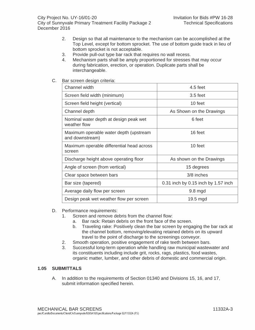
2. Design so that all maintenance to the mechanism can be accomplished at the Top Level, except for bottom sprocket. The use of bottom guide track in lieu of bottom sprocket is not acceptable.
3. Provide pull-out type bar rack that requires no wall recess.4. Mechanism parts shall be amply proportioned for stresses that may occur
during fabrication, erection, or operation. Duplicate parts shall be interchangeable.
C. Bar screen design criteria: Channel width 4.5 feet
Screen field width (minimum) 3.5 feet
Screen field height (vertical) 10 feet
Channel depth As Shown on the Drawings
Nominal water depth at design peak wetweather flow
6 feet
Maximum operable water depth (upstream and downstream)
16 feet
Maximum operable differential head across screen
10 feet
Discharge height above operating floor As shown on the Drawings
Angle of screen (from vertical) 15 degrees
Clear space between bars 3/8 inches
Bar size (tapered) 0.31 inch by 0.15 inch by 1.57 inch
Average daily flow per screen 9.8 mgd
Design peak wet weather flow per screen 19.5 mgd
D. Performance requirements:1. Screen and remove debris from the channel flow:
a. Bar rack: Retain debris on the front face of the screen.b. Traveling rake: Positively clean the bar screen by engaging the bar rack at
the channel bottom, removing/elevating retained debris on its upward travel to the point of discharge to the screenings conveyor.
2. Smooth operation, positive engagement of rake teeth between bars.3. Successful long-term operation while handling raw municipal wastewater and
its constituents including include grit, rocks, rags, plastics, food wastes, organic matter, lumber, and other debris of domestic and commercial origin.
1.05 SUBMITTALS
A. In addition to the requirements of Section 01340 and Divisions 15, 16, and 17,submit information specified herein.
City Project No. UY-16/01-20 Invitation for Bids #PW 16-28City of Sunnyvale Primary Treatment Facility Package 2 Technical SpecificationsDecember 2016
MECHANICAL BAR SCREENS 11332A-4 pw://Carollo/Documents/Client/CA/Sunnyvale/9265A10/Specifications/Package 02/11332A (FS)
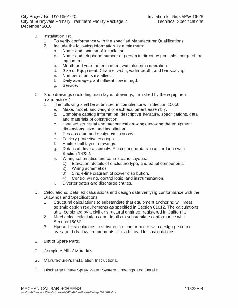
B. Installation list:1. To verify conformance with the specified Manufacturer Qualifications.2. Include the following information as a minimum:
a. Name and location of installation.b. Name and telephone number of person in direct responsible charge of the
equipment.c. Month and year the equipment was placed in operation.d. Size of Equipment: Channel width, water depth, and bar spacing.e. Number of units installed.f. Daily average plant influent flow in mgd. g. Service.
C. Shop drawings (including main layout drawings, furnished by the equipment manufacturer): 1. The following shall be submitted in compliance with Section 15050:
a. Make, model, and weight of each equipment assembly.b. Complete catalog information, descriptive literature, specifications, data,
and materials of construction.c. Detailed structural and mechanical drawings showing the equipment
dimensions, size, and installation.d. Process data and design calculations.e. Factory protective coatings.f. Anchor bolt layout drawings.g. Details of drive assembly. Electric motor data in accordance with
Section 16222. h. Wiring schematics and control panel layouts:
1) Elevation, details of enclosure type, and panel components.2) Wiring schematics. 3) Single-line diagram of power distribution. 4) Control wiring, control logic, and instrumentation.
i. Diverter gates and discharge chutes.
D. Calculations: Detailed calculations and design data verifying conformance with the Drawings and Specifications: 1. Structural calculations to substantiate that equipment anchoring will meet
seismic design requirements as specified in Section 01612. The calculations shall be signed by a civil or structural engineer registered in California.
2. Mechanical calculations and details to substantiate conformance with Section 15050.
3. Hydraulic calculations to substantiate conformance with design peak and average daily flow requirements. Provide head loss calculations.
E. List of Spare Parts.
F. Complete Bill of Materials.
G. Manufacturer's Installation Instructions.
H. Discharge Chute Spray Water System Drawings and Details.
City Project No. UY-16/01-20 Invitation for Bids #PW 16-28City of Sunnyvale Primary Treatment Facility Package 2 Technical SpecificationsDecember 2016
MECHANICAL BAR SCREENS 11332A-5 pw://Carollo/Documents/Client/CA/Sunnyvale/9265A10/Specifications/Package 02/11332A (FS)
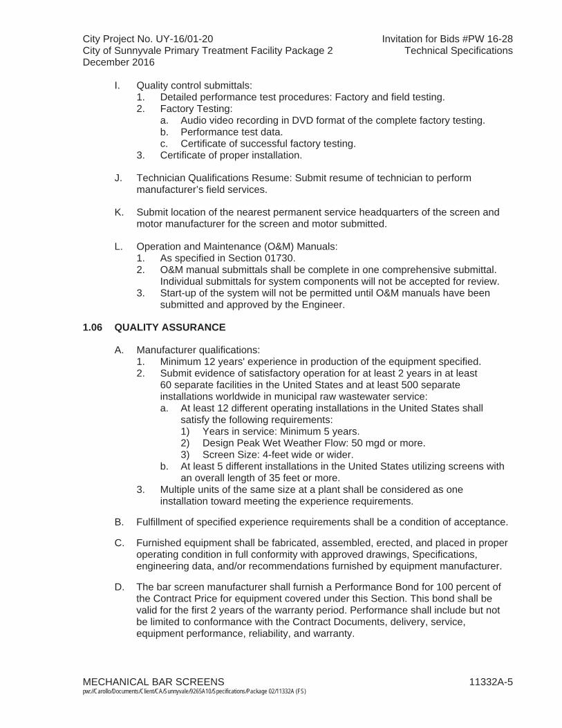
I. Quality control submittals:1. Detailed performance test procedures: Factory and field testing.2. Factory Testing:
a. Audio video recording in DVD format of the complete factory testing.b. Performance test data.c. Certificate of successful factory testing.
3. Certificate of proper installation.
J. Technician Qualifications Resume: Submit resume of technician to perform manufacturer’s field services.
K. Submit location of the nearest permanent service headquarters of the screen and motor manufacturer for the screen and motor submitted.
L. Operation and Maintenance (O&M) Manuals:1. As specified in Section 01730. 2. O&M manual submittals shall be complete in one comprehensive submittal.
Individual submittals for system components will not be accepted for review.3. Start-up of the system will not be permitted until O&M manuals have been
submitted and approved by the Engineer.
1.06 QUALITY ASSURANCE
A. Manufacturer qualifications:1. Minimum 12 years' experience in production of the equipment specified.2. Submit evidence of satisfactory operation for at least 2 years in at least
60 separate facilities in the United States and at least 500 separate installations worldwide in municipal raw wastewater service:a. At least 12 different operating installations in the United States shall
satisfy the following requirements:1) Years in service: Minimum 5 years.2) Design Peak Wet Weather Flow: 50 mgd or more.3) Screen Size: 4-feet wide or wider.
b. At least 5 different installations in the United States utilizing screens with an overall length of 35 feet or more.
3. Multiple units of the same size at a plant shall be considered as oneinstallation toward meeting the experience requirements.
B. Fulfillment of specified experience requirements shall be a condition of acceptance.
C. Furnished equipment shall be fabricated, assembled, erected, and placed in proper operating condition in full conformity with approved drawings, Specifications, engineering data, and/or recommendations furnished by equipment manufacturer.
D. The bar screen manufacturer shall furnish a Performance Bond for 100 percent of the Contract Price for equipment covered under this Section. This bond shall be valid for the first 2 years of the warranty period. Performance shall include but not be limited to conformance with the Contract Documents, delivery, service, equipment performance, reliability, and warranty.
City Project No. UY-16/01-20 Invitation for Bids #PW 16-28City of Sunnyvale Primary Treatment Facility Package 2 Technical SpecificationsDecember 2016
MECHANICAL BAR SCREENS 11332A-6 pw://Carollo/Documents/Client/CA/Sunnyvale/9265A10/Specifications/Package 02/11332A (FS)
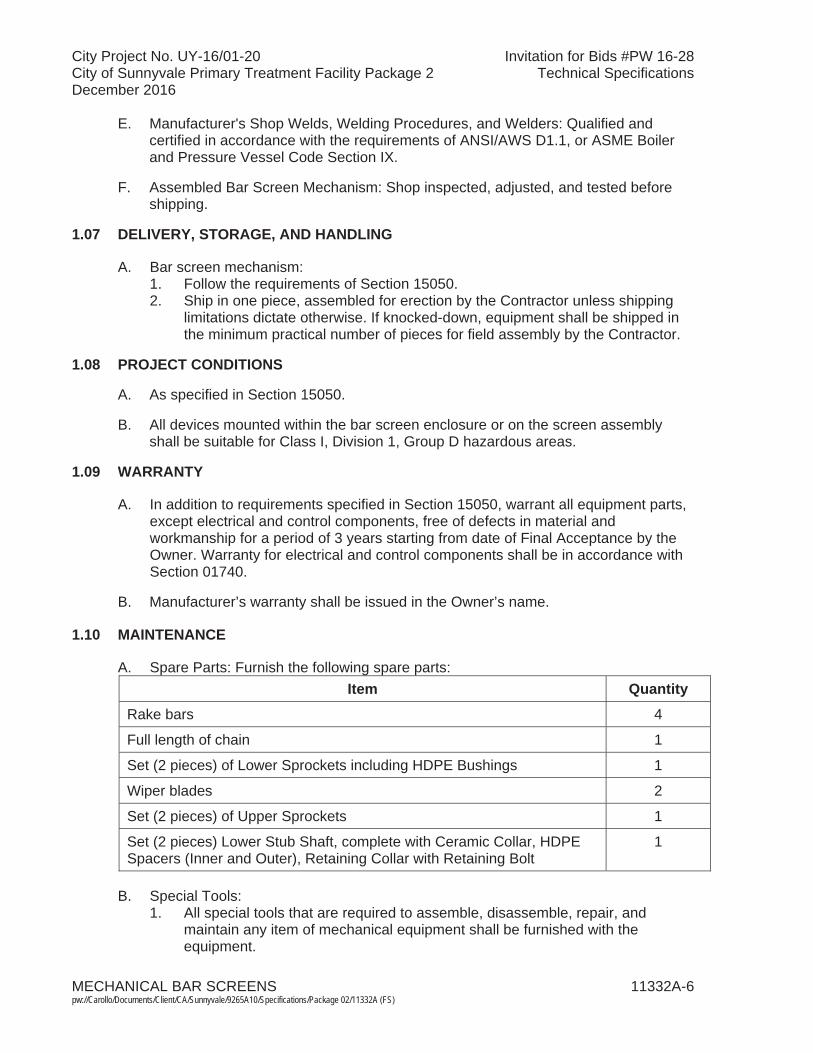
E. Manufacturer's Shop Welds, Welding Procedures, and Welders: Qualified and certified in accordance with the requirements of ANSI/AWS D1.1, or ASME Boiler and Pressure Vessel Code Section IX.
F. Assembled Bar Screen Mechanism: Shop inspected, adjusted, and tested before shipping.
1.07 DELIVERY, STORAGE, AND HANDLING
A. Bar screen mechanism:1. Follow the requirements of Section 15050. 2. Ship in one piece, assembled for erection by the Contractor unless shipping
limitations dictate otherwise. If knocked-down, equipment shall be shipped in the minimum practical number of pieces for field assembly by the Contractor.
1.08 PROJECT CONDITIONS
A. As specified in Section 15050.
B. All devices mounted within the bar screen enclosure or on the screen assembly shall be suitable for Class I, Division 1, Group D hazardous areas.
1.09 WARRANTY
A. In addition to requirements specified in Section 15050, warrant all equipment parts,except electrical and control components, free of defects in material and workmanship for a period of 3 years starting from date of Final Acceptance by theOwner. Warranty for electrical and control components shall be in accordance with Section 01740.
B. Manufacturer’s warranty shall be issued in the Owner’s name.
1.10 MAINTENANCE
A. Spare Parts: Furnish the following spare parts:Item Quantity
Rake bars 4
Full length of chain 1
Set (2 pieces) of Lower Sprockets including HDPE Bushings 1
Wiper blades 2
Set (2 pieces) of Upper Sprockets 1
Set (2 pieces) Lower Stub Shaft, complete with Ceramic Collar, HDPE Spacers (Inner and Outer), Retaining Collar with Retaining Bolt
1
B. Special Tools:1. All special tools that are required to assemble, disassemble, repair, and
maintain any item of mechanical equipment shall be furnished with the equipment.

City Project No. UY-16/01-20 Invitation for Bids #PW 16-28City of Sunnyvale Primary Treatment Facility Package 2 Technical SpecificationsDecember 2016
MECHANICAL BAR SCREENS 11332A-7 pw://Carollo/Documents/Client/CA/Sunnyvale/9265A10/Specifications/Package 02/11332A (FS)
2. Special tools shall include any type of tool that has been specifically made for use on an item of equipment for assembly, disassembly, repair, and maintenance.
3. When special tools are provided, they shall be marked or tagged and a list of such tools shall be included with the maintenance and operation instructions describing the use of each marked tool.
PART 2 PRODUCTS
2.01 MANUFACTURERS
A. Manufacturers: One of the following, modified as necessary to meet the Specification requirements: 1. Huber, Inc. - Rake Max Bar Screen. 2. Headworks, Inc. - Mahr Bar Screen.3. Or approved equal.
2.02 MATERIALS
A. All wetted and unwetted parts, including fasteners and hardware, except as specified herein: Type 316 stainless steel; Type 316L stainless steel if material is to be welded.
B. Bolts and nuts shall be of Type 316 stainless steel.
C. Anchor bolts shall be Type 316 stainless steel and furnished by the Contractor.
D. Lower Sprocket Bearing: Self-lubricating polyethylene with a ceramic collar bonded onto the stub shaft.
E. Steel and Stainless Steel: As specified in Section 05120.
F. After fabrication and welding has been completed, all stainless steel surfaces shall be glass bead blasted prior to equipment assembly. Bead blast shall remove all weld discoloration and surface contaminants and provide for spontaneous passivation as recognized in ASTM A380-99, Cleaning, Descaling, and Passivation of Stainless Steel Parts, Equipment, and Systems, 1. Scope, 1.1.1.1.
G. All stainless steel components shall be glass bead blasted.
2.03 EQUIPMENT
A. Equipment shall be the standard product of the manufacturer, modified as necessary to conform to the specifications.
2.04 COMPONENTS
A. Bar rack:1. Suitably reinforced to meet all anticipated loads including the specified
maximum operable differential head across the screen.
City Project No. UY-16/01-20 Invitation for Bids #PW 16-28City of Sunnyvale Primary Treatment Facility Package 2 Technical SpecificationsDecember 2016
MECHANICAL BAR SCREENS 11332A-8 pw://Carollo/Documents/Client/CA/Sunnyvale/9265A10/Specifications/Package 02/11332A (FS)
2. Bars: a. Screen bars shall be constructed of Type 316 stainless steel. Bar rack
shall consist of continuous taper section bars as specified. Rectangular bars shall not be allowed.
b. Screen bars shall be individually replaceable without any welding or cutting. Screen bars that are welded to the framework or welded into sub-assemblies shall not be allowed. Replacement screen bars shall be available from the screen manufacturer.
c. Continuous for full height of bar rack. Bars shall be fastened to a dead plate that extends to the point of discharge.
d. Bars shall be supported from framework and be readily removable. e. If required, provide additional horizontal braces on the back side of the bar
rack to withstand high differential head across the screen. Each brace shall include angled supports that bolt to the side channel walls.
B. Dead plate:1. Dead plate of Grade 316 stainless steel plate (thickness of 10/64 inch,
minimum) shall extend to the point of discharge.2. Dead plate shall be true and flat, such that a close clearance between the
raking tines and the plate can be maintained during the cleaning cycle.3. Backside of dead plate shall be constructed to guarantee a maximum gap
between rake bar and dead plate, leading to the discharge chute without interruption.
4. Reinforce backside of dead plate with 316 stainless steel angles with a thickness of 3/16 inch installed horizontally at least every 27 inches along the dead plate. Also, provide 316 stainless steel angles with a thickness of 3/16 inch installed vertically between the horizontal angles for rigidity.
5. Extend from top of the bar rack to the discharge chute.
C. Discharge Chute:1. 11-gauge minimum Type 316L stainless steel, suitably reinforced.2. Extend from dead plate to the point above the screenings conveyor shown on
the Drawings.3. Include sides to contain/direct screenings to the screenings conveyor.
D. Diverter chute assembly: 1. Type 316L stainless steel, suitably reinforced.2. A framework of 10/64-inch stainless steel plate with a diverter plate of
11 gauge welded to a Schedule 40 Pipe of diameter 1.00 inch. The pipe shall be then attached to a handle. A desired position of the diverter plate is selected by means of the handle to either allow or not allow the screenings to fall into the conveyor hopper. The screenings diverter plate shall close any gaps with the discharge chute of the bar screen when the intention is to divert the screenings into a disposal container.
3. Diverter chute shall be mounted out of the normal screenings discharge path.
E. Screen framework:1. Framework of screen shall be constructed of Type 316 stainless steel and
cross section with a minimum thickness of 10/64 inch.

City Project No. UY-16/01-20 Invitation for Bids #PW 16-28City of Sunnyvale Primary Treatment Facility Package 2 Technical SpecificationsDecember 2016
MECHANICAL BAR SCREENS 11332A-9 pw://Carollo/Documents/Client/CA/Sunnyvale/9265A10/Specifications/Package 02/11332A (FS)
2. Various parts fastened by welding, riveting, or bolting shall be braced as necessary to ensure a rigid structure.
3. Side frames shall be 10/64 inch, formed to a channel profile.4. Bottom thickness shall be 10/64 inch.5. Frame shall have Grade 316 Stainless Steel wrap around stiffeners with a
U-profile thickness of 3/16 inch at least every 54 inches above the maximum water line for rigidity.
6. Screen Frame shall be supplied in one piece requiring no field assembly. 7. Suitably reinforced to support the required loads.
F. Lower sprocket:1. Two per bar screen.2. Pitch: 160 mm.3. Tooth width: 27 mm.4. Outer hub diameter: 110/115 mm.5. Inner hub diameter: 70 mm.6. Stub shaft mount: 230 by 15 mm.7. Stub axle diameter: 60 mm.8. Sprocket bushing diameter: dia 70/dia 60 by 60 mm (HDPE).9. Sprocket minimum thickness: 27 mm.10. The use of bottom guide track in lieu of lower sprocket is not acceptable.
G. Lower bearing:1. Lower bearing shall be self-lubricating polyethylene material and be
maintenance free.2. A ceramic collar shall be bonded onto the stub shaft.3. No lower bearing requiring lubrication shall be allowed.
H. Upper sprocket:1. Two per bar screen.2. Pitch: 160 mm.3. Tooth width: 27 mm.4. Sprockets minimum thickness: 27 mm.
I. Upper bearing:1. UCFX 4 – Bolt Flange Bearings or equal mounted in the Take-Up Frame
assembly.2. Grease-lubricated.3. Take-up screw: Acme Lead Screw made of 18-8 stainless steel. No threaded
rod shall be allowed.
J. Chains:1. The chains shall be true roller-type chains made of Type 316 stainless steel.
Rollers shall be stainless steel. No other material shall be allowed.2. The chain link shall measure 160 mm centerline to centerline and be minimum
1/4-inch thick.3. The maximum allowable chain pull shall be minimum 112,000 Newtons
(24,179 pound-force).4. Chain rollers are to be a minimum of 2-inch diameter.5. Breaking strength: 31,000 pound-force.
City Project No. UY-16/01-20 Invitation for Bids #PW 16-28City of Sunnyvale Primary Treatment Facility Package 2 Technical SpecificationsDecember 2016
MECHANICAL BAR SCREENS 11332A-10pw://Carollo/Documents/Client/CA/Sunnyvale/9265A10/Specifications/Package 02/11332A (FS)
K. Chain guides:1. The chain guides shall be bolted to the screen frame and adjustable to ensure
accurate penetration of the rakes into the bar rack.2. The chain guide shall have an L-profile of minimum dimensions
2.65 inch/1.38 inch/0.19 inch (65 mm/35 mm/4 mm) and be manufactured of Type 316 stainless steel.
3. The chain guides shall be fixed to the screen frame from the maximum water level to the bottom of the channel for both the upward traveling and downward traveling chain.
4. The chain guides shall not protrude into the flow.5. Replaceable wear strips on the chain guides below the water level shall not be
allowed.
L. Shafting:1. All shafting shall be straight, true, and of sufficient section to transmit the
power required. Keyways with fitted keys shall be provided at the upper sprocket connections.
M. Rake assembly:1. Operates to remove debris from the bar rack and convey it over the dead plate
to the wiper assembly for removal.2. Rakes:
a. Teeth:1) Precision cut from a single continuous 5/16-inch, Type 316L stainless
steel bar.2) Tines designed to mesh with and extend between the bars of the bar
rack with sufficient penetration of the bar rack to ensure that screenings are completely cleared during each lifting operation.
b. Rake lifting capacity: Minimum 1,000 pounds of live load.3. Rake teeth shall consistently ride within 1/8 to 1/4 inch of dead plate surface.4. Under normal operating conditions, rake shall be oriented 90 degrees to the
bar rack to positively remove captured debris from the bar rack.5. Rake mechanism shall be capable of traveling at two speeds. Normal speed
shall be an approximately 10-second cleaning interval and high speed shall be an approximately 5-second cleaning interval.
N. Wiper:1. Designed to pivot to effectively remove debris from the rake on each pass.2. Wiper arm: Type 316 stainless steel plate welded to structural tubing.3. Wiper blade: UHMW PE, adjustable.4. Wiper mechanism shall be fitted with a compression spring that allows the
scraper to return to its resting position smoothly, without shock.
O. Discharge chute spray system:1. Designed and provided by bar screen manufacturer as part of the bar screen
package.2. Water spray to move screenings material down the discharge chute and into
the screenings conveyor.3. Piping, fittings, and valves shall be as specified in Division 15.
City Project No. UY-16/01-20 Invitation for Bids #PW 16-28City of Sunnyvale Primary Treatment Facility Package 2 Technical SpecificationsDecember 2016
MECHANICAL BAR SCREENS 11332A-11pw://Carollo/Documents/Client/CA/Sunnyvale/9265A10/Specifications/Package 02/11332A (FS)
4. Manufacturer shall provide and install on the bar screen unit a spray bar and piping routed to the point where it clears the bar screen mechanism for connection to field-routed piping provided by the Contractor.
5. Components:a. Solenoid valve: Suitable for installation in Class 1, Division 1, Group D
hazardous area. Locate outside of screen enclosure.b. Spray nozzles:
1) As specified in Section 15120.c. Piping and pipe supports:
1) Type 316 stainless steel.2) Piping supported from bar screen unit so that it does not interfere
with the bar screen operation or cause screenings to hang up.
P. Sealing side frames:1. Buna-N Rubber Flaps shall run along the side of the frame for the full depth of
the channel and seal the screen to the channel walls to ensure that none of the flow bypasses the screen.
Q. Covers:1. The bar screen shall be completely enclosed above the operating floor. 2. All covers shall be constructed of Type 316 stainless steel.3. Covers shall permit easy removal for maintenance purposes. 4. Provide hinged double doors on front cover.5. Covers shall extend over the discharge chute on the back (downstream) side
of screen with flanged connection to the diverter chute. Provide opening withhinged double doors at discharge area.
6. Covers shall be provided by the screen manufacturer.7. Provide flanged connection, with neoprene gasket, for foul air duct connection,
sized and located as shown on the Drawings.
R. Drive:1. Electric motor driven controlled by a VFD, rated for continuous operation.2. Designed for installation in Class 1, Division 1, Group D hazardous location.3. Locate motor for each screen on the side of the screen indicated on the
Drawings.4. Use of a belt drive is not acceptable.5. Motor:
a. Inverter duty rated for VFD, continuous duty, squirrel-cage induction type electric motor. Designed, manufactured, and tested in accordance with NEMA MG1 Part 31.
b. Conform to the requirements of Sections 15050, 16222, and 16262. c. Provide motor winding heater and temperature switches (suitable for
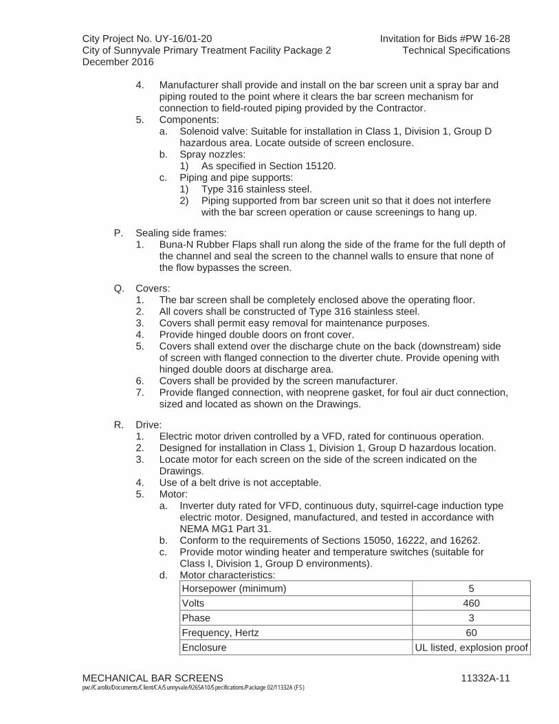
Class I, Division 1, Group D environments). d. Motor characteristics:
Horsepower (minimum) 5 Volts 460Phase 3Frequency, Hertz 60Enclosure UL listed, explosion proof
City Project No. UY-16/01-20 Invitation for Bids #PW 16-28City of Sunnyvale Primary Treatment Facility Package 2 Technical SpecificationsDecember 2016
MECHANICAL BAR SCREENS 11332A-12pw://Carollo/Documents/Client/CA/Sunnyvale/9265A10/Specifications/Package 02/11332A (FS)
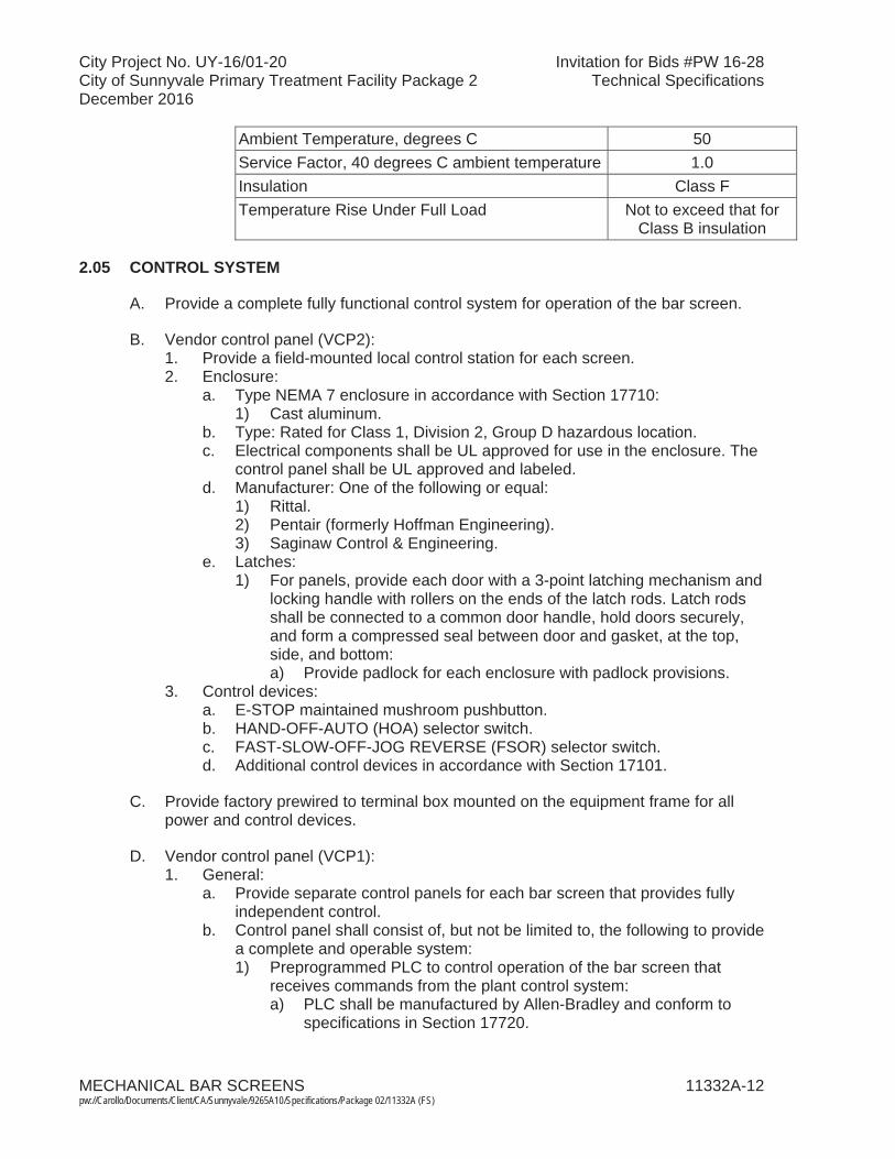
Ambient Temperature, degrees C 50Service Factor, 40 degrees C ambient temperature 1.0Insulation Class FTemperature Rise Under Full Load Not to exceed that for
Class B insulation
2.05 CONTROL SYSTEM
A. Provide a complete fully functional control system for operation of the bar screen.
B. Vendor control panel (VCP2): 1. Provide a field-mounted local control station for each screen. 2. Enclosure:
a. Type NEMA 7 enclosure in accordance with Section 17710: 1) Cast aluminum.
b. Type: Rated for Class 1, Division 2, Group D hazardous location.c. Electrical components shall be UL approved for use in the enclosure. The
control panel shall be UL approved and labeled.d. Manufacturer: One of the following or equal:
1) Rittal.2) Pentair (formerly Hoffman Engineering). 3) Saginaw Control & Engineering.
e. Latches:1) For panels, provide each door with a 3-point latching mechanism and
locking handle with rollers on the ends of the latch rods. Latch rods shall be connected to a common door handle, hold doors securely, and form a compressed seal between door and gasket, at the top, side, and bottom:a) Provide padlock for each enclosure with padlock provisions.
3. Control devices: a. E-STOP maintained mushroom pushbutton.b. HAND-OFF-AUTO (HOA) selector switch.c. FAST-SLOW-OFF-JOG REVERSE (FSOR) selector switch.d. Additional control devices in accordance with Section 17101.
C. Provide factory prewired to terminal box mounted on the equipment frame for all power and control devices.
D. Vendor control panel (VCP1): 1. General:
a. Provide separate control panels for each bar screen that provides fully independent control.
b. Control panel shall consist of, but not be limited to, the following to providea complete and operable system:1) Preprogrammed PLC to control operation of the bar screen that
receives commands from the plant control system: a) PLC shall be manufactured by Allen-Bradley and conform to
specifications in Section 17720.
City Project No. UY-16/01-20 Invitation for Bids #PW 16-28City of Sunnyvale Primary Treatment Facility Package 2 Technical SpecificationsDecember 2016
MECHANICAL BAR SCREENS 11332A-13pw://Carollo/Documents/Client/CA/Sunnyvale/9265A10/Specifications/Package 02/11332A (FS)
2) Variable frequency drive (VFD) with motor circuit protector disconnect.
3) Hardwired interlocks to shut down the equipment in all modes of operation and activates Fail Alarms upon any of the following conditions:a) Motor overload.b) High Temperature.
c. Control panel shall be located in an unclassified area.d. Control panel shall carry a UL label certifying the assembled industrial
control panel complies with UL 508.e. Control panel shall be completely prewired, preprogrammed, and factory
tested for proper operation prior to shipment. Refer to Section 17950 for additional testing requirements.
f. Communicate with the plant control system over DLR Ethernet/IP as shown on the control system block diagram.
g. Provide separate alarm and emergency shutdown functions.h. Provide local operator interface (LOI) unit for adjustment of setpoints,
timers, and alarms.2. Panel enclosure and components:
a. VCP enclosure type:1) Floor-mount, steel, NEMA 12 rated with hinged doors for front access
as specified in Section 17710: a) Steel with gasketed door, dust-tight.
2) The VCP enclosure shall be adequately sized and designed to dissipate the heat generated inside the enclosure. Provide a fan kit as specified in Section 17710 as needed.
3) Each VCP enclosure shall not exceed the following dimensions: 84-inches high by 72-inches wide by 36-inches deep. Coordinateenclosure size with available space where the panels are intended to be installed.
4) Manufacturer: One of the following or equal:a) Rittal.b) Pentair (formerly Hoffman Engineering). c) Saginaw Control & Engineering.
5) Latches:a) For panels, provide each door with a 3-point latching
mechanism and locking handle with rollers on the ends of the latch rods. Latch rods shall be connected to a common door handle, hold doors securely, and form a compressed seal between door and gasket, at the top, side, and bottom:(1) Provide padlock for each enclosure with padlock provisions.
b. Components including enclosures shall conform with requirements of Section 17710:1) Design controls such that the equipment cannot operate unless
controls are energized.2) Instruments mounted on the face of the panel and components
located within the panel shall meet the requirements specified in Section 17710.
3) Controls and instruments shall fail into a safe condition.
City Project No. UY-16/01-20 Invitation for Bids #PW 16-28City of Sunnyvale Primary Treatment Facility Package 2 Technical SpecificationsDecember 2016
MECHANICAL BAR SCREENS 11332A-14pw://Carollo/Documents/Client/CA/Sunnyvale/9265A10/Specifications/Package 02/11332A (FS)
4) Provide necessary interlocks and time delays (operator adjustable) for system control.
5) Indicators and Alarms in accordance with Sections 17710 and 17101.c. Power systems:
1) Power supply to panel: 480-volt, 60-Hz, 3-phase.2) Provide main circuit breaker flange-mounted power disconnect
interlocked to the enclosure door:a) VCP shall be labeled and rated to withstand the available fault
current as to be determined in the study per Section 16305.b) In accordance with Section 16412.
3) Provide surge protection device.4) Provide duplex GFCI protected, 120-volt, 60-Hertz, 1-phase
receptacle.5) Provide redundant 24 VDC regulated power supply.6) Provide true on-line double conversion uninterruptible power supply
(UPS) to power PLC, network, and instrumentation equipment. UPS shall conform with requirements of Section 17712.
d. VFD:1) Shall be supplied by the equipment manufacturer.2) Shall conform to the requirements of Section 16262.3) Mounted in the bar screen vendor control panel (VCP).4) Overload Protection:
a) VFD shall have integral solid-state overload.5) VFD filter:
a) The design has a physical separation between the VFD and bar screen motor of approximately 300 feet.
6) Manufactured by Allen-Bradley/Rockwell Automation.e. Provide current sensor relays for screen motor.f. Provide auxiliary contacts to energize screen motor winding heaters when
the equipment is not active.g. Local Operator Interface (LOI) in accordance with Section 17721:
1) NEMA 12 rated.2) 10-inch configurable color LCD touchscreen with a minimum
resolution of 640 by 480 pixels.3) 32 MB Flash EPROM Memory.
h. Programmable logic controller for automatic control of devices in accordance with Section 17720: 1) Acceptable manufacturers, no equal:
a) Rockwell Automation:(1) ControlLogix.(2) CompactLogix.
2) The PLC programming software system shall be manufactured by PLC hardware manufacturer:a) Rockwell Software:
(1) RSLogix 5000.3) Central processing unit:
a) Configure each central processor unit so that it contains all the software relays, timers, counters, number storage registers, shift registers, sequencers, arithmetic capability, and comparators necessary to perform the specified control functions.
City Project No. UY-16/01-20 Invitation for Bids #PW 16-28City of Sunnyvale Primary Treatment Facility Package 2 Technical SpecificationsDecember 2016
MECHANICAL BAR SCREENS 11332A-15pw://Carollo/Documents/Client/CA/Sunnyvale/9265A10/Specifications/Package 02/11332A (FS)
b) Capable of interfacing with all discrete inputs, analog inputs, discrete outputs, analog outputs and communication cards to meet the specified requirements.
c) Capable of supporting and implementing closed loop floating-point math and PID control that is directly integrated into the CPU control program.
4) 120 VAC Power Supply.5) Surge protection for all of the controls. 6) Ethernet/IP Communications module (connection to LOI). 7) DLR Ethernet/IP Communications module (communication to
Owners Control system).8) 120 VAC Isolated Discrete Inputs (16 points max/module).9) 120 VAC Isolated Discrete Outputs (16 points max/module).10) 4-20 mA HART Analog Input module.11) Capable of utilizing a second Ethernet/IP module.12) Control Function in accordance with Section 17101.
i. Wiring:1) Factory assemble and wire the control panel such that field wiring
shall consist only of connections to terminals.2) Identify each end of each wire by a unique wire number printed on a
heat shrink sleeve marker.j. Provide Allen Bradley 1783-ETAP module for DLR network diagnostics.k. Panel instruments as shown on the Drawings, as specified in
Section 17710, and as recommended by the equipment manufacturer to provide a complete operational system.
3. Indicators, alarms, and controls accessible through VCP Operator Interface Unit:a. Elapsed time meter.b. Alarm indication providing description of specific faults.c. Control setpoints for differential level ad timer.
4. Provide contacts rated for 10A at 120VAC for remote monitoring of the status signals listed in Section 17101.
5. Auto Reverse Program shall run screen in low speed only.6. Data to transmit to the Owner’s control system over Ethernet/IP:
a. Bar Screen Overview: 1) Operation Status. 2) Motor Status. 3) Control Selection (REMOTE/LOCAL). 4) Running – Low Speed Indication.5) Running – High Speed Indication.6) Stopped.7) Run Time Indication.8) Refer to Section 17101 for additional indicators and alarms.
b. Bar Screen Status: 1) Hand/Auto/Off Selection. 2) Fault Status.
c. Alarm Management: 1) List of Active Alarms.

City Project No. UY-16/01-20 Invitation for Bids #PW 16-28City of Sunnyvale Primary Treatment Facility Package 2 Technical SpecificationsDecember 2016
MECHANICAL BAR SCREENS 11332A-16pw://Carollo/Documents/Client/CA/Sunnyvale/9265A10/Specifications/Package 02/11332A (FS)
7. Operator screen information: Manufacturer will provide the following screensand subsequent information on the Local Operator Interface:a. Information on the Operator Screens:
1) Main Menu: a) Login. b) Navigation Buttons to the screens listed below.
2) Bar Screen Overview: a) Operation Status. b) Motor Status. c) Control Selection (REMOTE/LOCAL).
3) Bar Screen Status: a) Hand/Remote/Off Selection. b) Fault Status. c) VFD Fault Status. d) Motor Status. e) Screen Cycles Completed Display. f) Cycle Time Display. g) Last Cycle Time Display.
4) Alarm Management: a) List of Active Alarms. b) Alarm History.
5) System Information: a) Text display indicating the following.
(1) Company. (2) Service Contact info. (3) Job Number. (4) Installed date. (5) PLC IP address. (6) LOI IP address. (7) Programmer IP address.
6) PLC Status: a) Processor Mode. b) Error Codes. c) Help button to decipher error codes.
7) I/O Status: a) I/O Map indicating the following. b) I/O point, Status, and description. c) Indicating On/Off status.
8) Trend: a) Screen Running.
9) Trend Setup: a) Screen Running.
10) Maintenance: a) Run Time Hours. b) Next Weekly Service Count Down Hours. c) Next Monthly Service Count Down Hours. d) Next Bi-Annual Service Count Down Hours. e) Run Time Reset. f) Next Weekly Service Count Down Reset.
City Project No. UY-16/01-20 Invitation for Bids #PW 16-28City of Sunnyvale Primary Treatment Facility Package 2 Technical SpecificationsDecember 2016
MECHANICAL BAR SCREENS 11332A-17pw://Carollo/Documents/Client/CA/Sunnyvale/9265A10/Specifications/Package 02/11332A (FS)
g) Next Monthly Service Count Down Reset. h) Next Bi-Annual Service Count Down Reset.
11) User Settings: a) Touch Calibration setup. b) User setup. c) Password manager. d) Time/Date setup.
8. Vendor equipment programming meetings: Attend a meeting with the Programmer to coordinate with the owners control system. The meeting discussion point will include the following at a minimum:a. Tag Naming Conventions. b. PLC to PLC global data mapping. c. All PLCs to HMI tags mapping. d. LOI screen colors and navigation. e. Interlock and Permissive definitions. f. Communication Methods. g. Standard code blocks for common control functionality. h. Alarms – clearing, formats, colors, and status.
E. Level sensors: 1. Provide ultrasonic level sensors in accordance with Section 17206. 2. Level elements shall be rated for installation in a Class 1, Division 1, Group D
hazardous location.
F. Proximity switches:1. Provide for monitoring of home position and over torque condition if required
for complete and operable system.2. Enclosure:
a. Type: Rated for Class 1, Division 1, Group D hazardous location.b. Material: Type 316 stainless steel.
G. Operation:1. Bar screens operation shall be controlled by the vendor control panel from
signals from the plant PCS.2. Reference Section 17101 for equipment and system operation requirements.
2.06 FABRICATION
A. Shop assembly:1. Bar screens shall be factory assembled and tested.2. Mount all accessories and appurtenances including, but not limited to, limit
switches and a discharge chute spray bar so complete system may be tested.3. Following successful testing, disassemble for field assembly by the Contractor.
2.07 FINISHES
A. Stainless Steel surfaces shall be treated per Article 2.02 herein.
B. All other surfaces:1. Factory prime, field prime, and finish coats as specified in Section 09960.
City Project No. UY-16/01-20 Invitation for Bids #PW 16-28City of Sunnyvale Primary Treatment Facility Package 2 Technical SpecificationsDecember 2016
MECHANICAL BAR SCREENS 11332A-18pw://Carollo/Documents/Client/CA/Sunnyvale/9265A10/Specifications/Package 02/11332A (FS)
2.08 SOURCE QUALITY CONTROL
A. Test equipment for proper performance at point of manufacture in accordance with Section 01756.
B. Non-witnessed factory testing: 1. Run bar screen mechanism to verify proper operation of the mechanism and
all controls:a. Smooth operation and positive engagement of rake teeth between bars.b. Functionality of all controls including control panel and limit switches.
2. Test discharge chute spray water system.3. Audio-video record the complete factory testing. Provide the recording in DVD
format. The manufacturer shall certify the recording was not edited or altered in any shape or form.
4. Submit certified copies of test results upon successful completion of factory testing.
PART 3 EXECUTION
3.01 INSTALLATION
A. Install as indicated on the Drawings and in strict conformance with the manufacturer’s installation instructions, shop drawings, and recommendations.
B. Prior to start-up, the equipment shall be inspected for proper alignment, quiet operation, proper connection, and satisfactory performance.
C. Interconnecting piping and wiring:1. Routed by the Contractor as shown on the Drawings.2. Coordinated with the bar screen manufacturer to ensure that it does not
interfere with the bar screen operation or cause the screenings to hang up.
3.02 FIELD QUALITY CONTROL
A. Field tests:1. Conduct tests in presence of and under direction of the manufacturer's
representative.2. Conduct tests in presence of the Engineer.3. Test each piece of equipment and each system for satisfactory operation
without excessive noise, vibration, overheating, etc.4. Perform field testing in accordance with Sections 01756 and 15958 Level 2,
and manufacturer's recommendations.5. Provide certified copies of test results.
B. Check and adjust all equipment for misalignments, clearances, supports, and adherence to safety standards.

City Project No. UY-16/01-20 Invitation for Bids #PW 16-28City of Sunnyvale Primary Treatment Facility Package 2 Technical SpecificationsDecember 2016
MECHANICAL BAR SCREENS 11332A-19pw://Carollo/Documents/Client/CA/Sunnyvale/9265A10/Specifications/Package 02/11332A (FS)
3.03 MANUFACTURER’S FIELD SERVICES
A. Contractor to coordinate field service work with the manufacturer’s representative, Owner, and Engineer prior to initiating such work.
B. Manufacturer shall furnish services of a qualified Manufacturer’s Representative, experienced in erection and operation of the supplied bar screen equipment, toprovide manufacturer’s field services as specified in Section 01756.
C. Manufacturer’s representative shall perform the following services as described below and as specified in Section 01756. The specified durations are the minimum required time on the job site. Additional services and/or longer durations shall be provided as needed at no cost to the Owner to meet the required quality of work. Work to be done in a minimum of 3 trips: 1. Installation assistance:
a. Advise/observe the Contractor on the installation of the bar screens.b. Provide additional assistance as required.
2. Installation inspection: 1 trip; 1 workday each trip: a. The manufacturer shall provide a certificate of proper installation following
inspection.3. Start-up/testing assistance: 2 workdays:
a. Prior to start-up, the equipment shall be inspected for proper alignment, operation, and satisfactory performance.
b. Provide additional start-up/testing assistance as required. 4. Training: As specified in Section 01756. Provide training as follows:
a. Operations training: 4 hours of training, presented twice, for a total of 8 hours.
b. Mechanical maintenance training: 4 hours of training, presented twice, for a total of 8 hours.
c. Electrical maintenance training: 1 hour of training, presented twice, for a total of 2 hours.
d. Instrumentation training: 2 hours of training, presented twice for a total of 4 hours.
5. Final acceptance checkout: 2 workdays.
D. Refer to Section 17950 for additional requirements.
END OF SECTION


City Project No. UY-16/01-20 Invitation for Bids #PW 16-28City of Sunnyvale Primary Treatment Facility Package 2 Technical SpecificationsDecember 2016
SCREENINGS WASHER/COMPACTORS 11333-1 pw://Carollo/Documents/Client/CA/Sunnyvale/9265A10/Specifications/Package 02/11333 (FS)
SECTION 11333
SCREENINGS WASHER/COMPACTORS
PART 1 GENERAL
1.01 SUMMARY
A. Section includes: Screenings washer/compactors:1. Equipment Tag Numbers:
a. Screenings Washer/Compactor No. 1 - WCP-212.111. b. Screenings Washer/Compactor No. 2 - WCP-212.112. c. Tipping Trough No. 1 - TTR-212.211.d. Tipping Trough No. 2 - TTR-212.212.
B. Related sections:1. The Contract Documents are complementary; what is called for by one is as
binding as if called for by all.2. It is the Contractor’s responsibility for scheduling and coordinating the Work of
subcontractors, suppliers, and other individuals or entities performing or furnishing any of Contractor’s Work.
3. The following Sections are related to the Work described in this Section. This list of Related Sections is provided for convenience only and is not intended to excuse or otherwise diminish the duty of the Contractor to see that the completed Work complies accurately with the Contract Documents:a. Section 01010 - Summary of Work.b. Section 01340 - Shop Drawings, Product Data and Samples.c. Section 01610 - Project Design Criteria.d. Section 01612 - Seismic Design Criteria.e. Section 01756 - Testing, Training, and Facility Start-Up.f. Section 01730 - Operations and Maintenance Data.g. Section 09960 - High Performance Coatings.h. Section 13448 - Intelligent Actuators. i. Section 15050 - Common Work Results for Mechanical Equipment. j. Section 15116 - Plug Valves.k. Section 15118 - Pressure Reducing and Pressure Relief Valves.l. Section 15958 - Mechanical Equipment Testing.m. Section 16050 - General Requirements for Electrical Work. n. Section 16134 - Boxes.o. Section 16222 - Low Voltage Motors up to 500 Horsepower. p. Section 17050 - Process Control and Instrumentation Systems General
Requirements.q. Section 17100 - Control Strategies.r. Section 17101 - Specific Control Strategies. s. Section 17710 - Control Systems - Panels, Enclosures, and Panel
Components.t. Section 17720 - Control Systems - Programmable Logic Controllers
Hardware.u. Section 17721 - Human Machine Interface Hardware.

City Project No. UY-16/01-20 Invitation for Bids #PW 16-28City of Sunnyvale Primary Treatment Facility Package 2 Technical SpecificationsDecember 2016
SCREENINGS WASHER/COMPACTORS 11333-2 pw://Carollo/Documents/Client/CA/Sunnyvale/9265A10/Specifications/Package 02/11333 (FS)
v. Section 17765 - Human Machine Interface Software.w. Section 17950 - Testing, Calibration, and Commissioning.x. Appendix A - Pre-negotiated Proposal for Screenings
Washer/Compactors.
C. Inclusion of a specific manufacturer’s name in the Specifications does not mean that the specific manufacturer’s standard product will be acceptable. Specified manufacturer’s or other manufacturer’s standard product shall be modified as required to comply with Drawings, Specifications, and service conditions specified.
D. All equipment shall conform to the requirements of Section 15050, Basic Mechanical Materials, and Methods, except as modified herein.
1.02 COST OF PRE-NEGOTIATED ITEMS
A. Cost for some of the items in this section of the Specifications has been pre-negotiated with the specified manufacturer and is included in one of the bid items in the bidding sheet. Refer to the bidding sheet and applicable pre-negotiated proposal included in Appendix A for more details. The Contractor shall provide additional items as indicated in the applicable pre-negotiated proposal included in Appendix A, even if they are not included in the Specifications and/or Drawings. The Contractor is very strongly cautioned to carefully review the applicable pre-negotiated proposal, because the pre-negotiated proposal does not include all the items included in the Specifications and Drawings. In addition to the cost indicated for the applicable bid item in the bidding sheet, the Contractor shall include in his bid the costs for the following:1. All items not specifically mentioned in the scope of supply of the
pre-negotiated proposal, but required per Specifications and Drawings and required to complete the installation to provide an operational system.
2. All other items indicated in the pre-negotiated proposal to be provided by others, by customer, by Owner, or any other similar designation:a. All freight and applicable taxes, unless specifically included in
pre-negotiated proposal.b. All labor, materials, and all other associated costs not included in the
pre-negotiated proposal but required per Specifications and Drawings and required to complete the installation to provide an operational system.
c. The Contractor and Manufacturer shall ensure that the other obligations defined in the pre-negotiated proposal (Memorandum of Agreement/MOA) are complied with. These include, but are not limited to, delivery, inspections, start-up, training, testing, and payment.
B. Schedule:1. The Contractor shall coordinate with the equipment supplier’s delivery
schedule to issue a purchase order at such time that equipment delivery will be completed at least 8 weeks in advance of the required date, as indicated in the Contractor’s approved construction schedule. In addition, the Contractor shall issue the purchase order no later than November 30, 2017.
2. The negotiated price included in the Bid Schedule is based on a delivery per the MOA Section VI-3. If the Contractor elects to have delivery after this time, the purchase price shall be adjusted in accordance with the MOA and the Contractor shall be responsible for such additional costs.
City Project No. UY-16/01-20 Invitation for Bids #PW 16-28City of Sunnyvale Primary Treatment Facility Package 2 Technical SpecificationsDecember 2016
SCREENINGS WASHER/COMPACTORS 11333-3 pw://Carollo/Documents/Client/CA/Sunnyvale/9265A10/Specifications/Package 02/11333 (FS)
C. Liquidated Damages:1. The manufacturer has agreed to the liquidated damages as described in the
Memorandum of Agreement.
1.03 REFERENCES
A. American Gear Manufacturer’s Association.
B. American Bearing Manufacturers Association (ABMA):1. ABMA 9 - Load Ratings and Fatigue Life for Ball Bearings.2. ABMA 11 - Load Ratings and Fatigue Life for Roller Bearings.
C. American Iron and Steel Institute (AISI).
D. American Society for Testing and Materials (ASTM): 1. A48 - Standard Specification for Gray Iron Castings.2. A108 - Standard Specification for Steel Bars, Carbon, Cold-Finished, Standard
Quality.3. A276 - Standard Specification for Stainless and Heat Resisting Steel Bars and
Shapes.4. A283 - Specification for Low and Intermediate Tensile Strength Carbon Steel
Plates.5. A743 - Standard Specification for Castings, Iron-Chromium, Iron-Nickel,
Corrosion Resistant, for General Application.6. E10 - Test Method for Brinell Hardness of Metallic Materials. 7. A36 - Structural Steel Specifications.8. A322 - Carbon and Alloy Steel Bar Specifications.
E. National Electrical Manufacturer's Association (NEMA):1. NEMA MG1.
F. American National Standard Institute (ANSI).
G. American Society of Mechanical Engineers (ASME).
H. National Electric Code (NEC).
1.04 SYSTEM DESCRIPTION
A. Screenings washer/compactor equipment shall be supplied as a complete systemby the manufacturer including washer/compactor unit, motors, valves, control panel, and all appurtenances necessary to provide a complete operating system.
B. Washer/compactor shall wash and dewater screenings removed from municipal wastewater by mechanical bar screens and conveyed to unit by a separate shaftless screw conveyor as indicated on the Drawings. Screenings washing shall be accomplished by vigorous mechanical agitation in a large volume of watercapable of breaking up putrescible organic matter and separating it from screenings material. Units that use only water sprays and pressing actions in combination with sprays will not be acceptable. After washing stage, washer/compactor shall
City Project No. UY-16/01-20 Invitation for Bids #PW 16-28City of Sunnyvale Primary Treatment Facility Package 2 Technical SpecificationsDecember 2016
SCREENINGS WASHER/COMPACTORS 11333-4 pw://Carollo/Documents/Client/CA/Sunnyvale/9265A10/Specifications/Package 02/11333 (FS)
dewater, compact, and transport washed screenings to a tipping trough to load ascreenings bin furnished by the Owner, for disposal. Dewatering and compaction of the screenings shall be accomplished using a pressing action produced by a shafted auger.
C. Washer/compactor shall consist of a transition chute from the conveyor to a screenings feed hopper, mechanical agitator, washing chamber, compaction zoneswith drain perforations, discharge conveyance pipe, flanged wash water and drain connections, drive unit, and a complete control system.
D. Raw screenings shall discharge from the conveyor through transition chute to washer/compactor inlet hopper and washing zone. Within washing zone, screenings material shall be batch washed in a water bath using vigorous agitation to break up fecal and other organic matter so it will pass through drain perforations with wash water and be separated from screenings material before compaction. At completion of mechanical wash cycle, wash water containing reduced fecal matter shall be drained from washing chamber through perforations to a drain pan and through a discharge pipe regulated by a motor operated plug valve.
E. A shafted auger is used to convey washed screenings through a preliminary compaction zone. Then, washed screenings are compacted and dewatered by shafted auger in main compaction zone and conveyed to discharge pipe for conveyance to a tipping trough where screenings are loaded in a dumpster.
1.05 DESIGN REQUIREMENTS
A. Screenings material will consist of material removed from raw municipal wastewater by mechanical bar screens with 3/8-inch bar spacing. The material will include rags, plastics, food wastes, organic matter, lumber, grit, rocks, and other debris ofdomestic and commercial origin.
B. Screening washer compactor:1. The screening washer compactor unit shall be capable of being operated in a
washing mode (batch mode) or continuous mode.2. During the continuous mode, raw screenings may be delivered to the washer
continuously and washed briefly. Screenings shall be removed and dewatered continuously by running the agitator and discharge drive simultaneously.
C. All mechanical parts shall be designed to handle the forces that may be exerted on them during fabrication, shipping, installation, and operation.
D. The screenings compactor unit shall be capable of minimum 50-percent weight volume reduction of the organic screenings material.
E. Screenings compactor unit shall discharge the screenings as shown on theDrawings.
City Project No. UY-16/01-20 Invitation for Bids #PW 16-28City of Sunnyvale Primary Treatment Facility Package 2 Technical SpecificationsDecember 2016
SCREENINGS WASHER/COMPACTORS 11333-5 pw://Carollo/Documents/Client/CA/Sunnyvale/9265A10/Specifications/Package 02/11333 (FS)
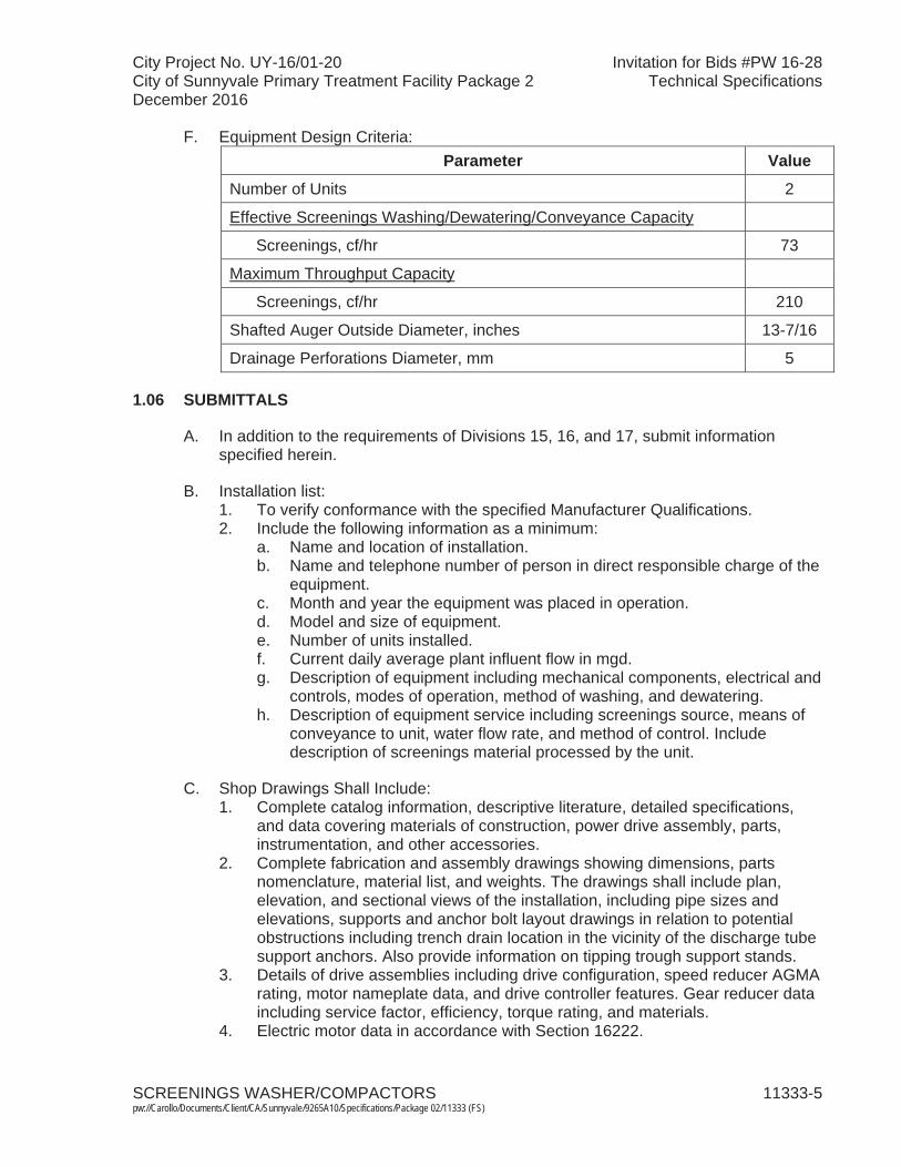
F. Equipment Design Criteria:Parameter Value
Number of Units 2
Effective Screenings Washing/Dewatering/Conveyance Capacity
Screenings, cf/hr 73
Maximum Throughput Capacity
Screenings, cf/hr 210
Shafted Auger Outside Diameter, inches 13-7/16
Drainage Perforations Diameter, mm 5
1.06 SUBMITTALS
A. In addition to the requirements of Divisions 15, 16, and 17, submit informationspecified herein.
B. Installation list:1. To verify conformance with the specified Manufacturer Qualifications.2. Include the following information as a minimum:
a. Name and location of installation.b. Name and telephone number of person in direct responsible charge of the
equipment.c. Month and year the equipment was placed in operation.d. Model and size of equipment.e. Number of units installed.f. Current daily average plant influent flow in mgd.g. Description of equipment including mechanical components, electrical and
controls, modes of operation, method of washing, and dewatering.h. Description of equipment service including screenings source, means of
conveyance to unit, water flow rate, and method of control. Include description of screenings material processed by the unit.
C. Shop Drawings Shall Include:1. Complete catalog information, descriptive literature, detailed specifications,
and data covering materials of construction, power drive assembly, parts, instrumentation, and other accessories.
2. Complete fabrication and assembly drawings showing dimensions, parts nomenclature, material list, and weights. The drawings shall include plan, elevation, and sectional views of the installation, including pipe sizes and elevations, supports and anchor bolt layout drawings in relation to potential obstructions including trench drain location in the vicinity of the discharge tube support anchors. Also provide information on tipping trough support stands.
3. Details of drive assemblies including drive configuration, speed reducer AGMA rating, motor nameplate data, and drive controller features. Gear reducer data including service factor, efficiency, torque rating, and materials.
4. Electric motor data in accordance with Section 16222.

City Project No. UY-16/01-20 Invitation for Bids #PW 16-28City of Sunnyvale Primary Treatment Facility Package 2 Technical SpecificationsDecember 2016
SCREENINGS WASHER/COMPACTORS 11333-6 pw://Carollo/Documents/Client/CA/Sunnyvale/9265A10/Specifications/Package 02/11333 (FS)
5. Elevation and schematics of local control panels and motor control enclosures. Details of enclosure type, single line diagram of power distribution, control wiring, control logic, panel components, and instrumentation.
6. Factory protective coatings.
D. Complete Bill of Materials.
E. Calculations: Detailed calculations and design data verifying conformance with the drawings and specifications:1. Structural calculations for complete system, including all welded joint details
and anchor bolts, signed by a Professional Engineer registered in California.2. Seismic design as specified in Section 01612.
F. Quality Control Submittals:1. Detailed Performance Test Procedures: Factory and field testing.2. Performance Test Data.3. Certificates:
a. Manufacturer’s certification that all welding was performed in accordance with American Welding Society (AWS) D1.1 Structural Welding Code, or equivalent.
b. Manufacturer’s certification that the entire equipment was passivated bysubmersion in an acid bath.
c. A copy of documents proving certification of the Manufacturer’s Quality Management System and Environmental Program.
d. Manufacturer’s certification that equipment was installed in accordance with manufacturer’s instructions, inspected by manufacturer, serviced with proper lubricants, and equipped with applicable safety equipment and controls.
G. Manufacturer's Installation Instructions.
H. List of Spare Parts and Special Tools.
I. List of recommended Spare Parts.
J. Operating instructions with descriptive literature.
K. Documentation of required maintenance for all equipment including an approved list of lubricants and the required quantities.
L. Operation and Maintenance (O&M) Manuals:1. As specified in Section 01730. 2. O&M manual submittals shall be complete in one comprehensive submittal.
Individual submittals for system components will not be accepted for review.3. Start-up of the system will not be permitted until O&M manuals have been
submitted and approved by the Engineer.
M. Technician Qualifications Resume: Submit resume of technician to perform Manufacturer’s Field Services.

City Project No. UY-16/01-20 Invitation for Bids #PW 16-28City of Sunnyvale Primary Treatment Facility Package 2 Technical SpecificationsDecember 2016
SCREENINGS WASHER/COMPACTORS 11333-7 pw://Carollo/Documents/Client/CA/Sunnyvale/9265A10/Specifications/Package 02/11333 (FS)
N. Training Course Outlines.
O. Submit location of nearest permanent service headquarters of washer/compactor and motor manufacturer.
P. Warranties.
1.07 QUALITY ASSURANCE
A. Manufacturer qualifications:1. Minimum 10-years’ experience in production of equipment substantially similar
to the specified equipment.2. Submit Installation List as specified to provide evidence of satisfactory
operation of equipment similar to the specified equipment in at least 25 separate facilities:a. Multiple equipment units at a plant shall be considered as one installation
toward meeting the experience requirements.b. A minimum of five installations shall have been in service for a minimum
of 4 years under similar operating conditions. References shall be of the same capacity or larger.
3. Minimum 7-years of experience in production for US installations of the specific equipment (model, style, and size) proposed for this project.
4. Fulfillment of the specified experience requirements shall be a condition of acceptance.
B. All equipment shall conform to requirements of Section 15050, except as modified herein.
C. Manufacturer's Shop Welds, Welding Procedures, and Welders: Qualified and certified in accordance with the requirements of ANSI/AWS D1.1, or ASME Boiler and Pressure Vessel Code Section IX.
D. Assembled Compactor Unit: Shop inspected, adjusted, and tested before shipping.
E. Furnished equipment shall be fabricated, assembled, erected, and placed in proper operating condition in full conformity with approved Drawings, Specifications, engineering data, and/or recommendations furnished by equipment manufacturer.
F. Screenings compactor units shall be factory assembled and then tested for a minimum of 8 hours prior to shipping.
G. Manufacturer shall have established quality management system and environmental program.
H. All stainless steel components and structures shall be fully submersed in a chemical bath of nitric acid and hydrofluoric acid (pickling bath) to remove any residues thatmay be present on the material as a result of forming, manufacture, or handling. After removal from pickling bath, equipment must be washed with a high-pressure wash of cold water to remove any remaining surface debris and promote formation of an oxidized passive layer, which is critical to the long life of the stainless steel.
City Project No. UY-16/01-20 Invitation for Bids #PW 16-28City of Sunnyvale Primary Treatment Facility Package 2 Technical SpecificationsDecember 2016
SCREENINGS WASHER/COMPACTORS 11333-8 pw://Carollo/Documents/Client/CA/Sunnyvale/9265A10/Specifications/Package 02/11333 (FS)
1.08 DELIVERY, STORAGE, AND HANDLING
A. All equipment shall be factory assembled and tested prior to shipment to ensure proper operation.
B. Ship fully assembled with all accessories.
C. Follow requirements of Section 01010 and Section 15050, and as specified herein.
D. Preparation for shipment:1. All materials shall be suitably packaged and braced to protect against damage
during transit, handling, and unloading.2. Manufacturer shall package equipment, be responsible for, and make good,
any and all damage until the equipment is delivered to the job site.3. Accessories shall be packaged separately in containers clearly marked
“ACCESSORIES ONLY.”4. A packing list, listing the contents of each container, shall be placed in a
moisture-proof envelope and securely fastened to the outside of the container.5. Provide written storage procedures for all equipment.
E. Delivery to Job Site:1. Manufacturer shall fabricate and deliver materials to the job site in
conformance with the Contractor’s construction schedule to minimize handling and on-site storage of equipment.
2. Individual equipment shall be delivered to the site fully assembled. If shipping requirements require minor disassembly, equipment shall be shipped in the minimum practical number of pieces for field assembly by Contractor.
3. Contractor shall be responsible for unloading the equipment at the time of delivery and hoisting the units from an open-top container.
F. Storage and Protection:1. Protect system components at site and during installation prior to project
completion in accordance with manufacturer’s recommendations. As aminimum, provide cover, ventilation, and proper stacking to prevent warping of any equipment stored on site.
1.09 PROJECT CONDITIONS
A. Environmental Requirements: As specified in Section 01610.
B. Area classifications:1. All compactor equipment, except the vendor control panel and tipping troughs,
shall be suitable for installation in Class I, Division 1, Group D hazardous locations.
C. Vendor Control Panel and tipping troughs shall be located in an unclassified area.
1.10 WARRANTY
A. Provide a warranty meeting the requirements of Section 01740.
City Project No. UY-16/01-20 Invitation for Bids #PW 16-28City of Sunnyvale Primary Treatment Facility Package 2 Technical SpecificationsDecember 2016
SCREENINGS WASHER/COMPACTORS 11333-9 pw://Carollo/Documents/Client/CA/Sunnyvale/9265A10/Specifications/Package 02/11333 (FS)
B. Extended Warranty:1. The Manufacturer shall provide a 1 year extended warranty on all parts,
materials, and labor.2. The extended warranty period shall start at the end of the Contractor's General
Warranty as defined in Section 01740. 3. The Extended Warranty shall be issued in the Owner’s name.
C. When work covered by the warranty has failed and been corrected by replacement or rebuilding, reinstate the warranty by written endorsement. The reinstated warranty shall be equal to the original warranty with an equitable adjustment for depreciation.
1.11 MAINTENANCE
A. Furnish parts, packed and labeled for warehousing and in accordance with Section 15050.
B. Spare parts for screenings washer compactor:1. Three complete brush assemblies with clips and fasteners.2. Two complete sets of wear bars.3. Two sets of thrust bearings.4. Three agitator seal replacement kits.5. Two solenoid valves (wash water system).
C. Include a price list and name, address, and telephone number of local supplier.
D. Special Tools: Furnish any special tools required for maintenance and disassembly of furnished equipment. When special tools are provided, they shall be marked or tagged and a list of such tools shall be included with the maintenance and operation instructions describing the use of each marked tool.
PART 2 PRODUCTS
2.01 MANUFACTURER
A. Manufacturers: 1. Wash and Press/Super Launder (WAP-SL) Size 6, as manufactured by Huber
Technology, Inc.
2.02 MATERIALS
A. All parts and assemblies shall be fabricated from sheets and shapes (rods, angles, and channels) of Type 316L stainless steel unless otherwise specified.
B. All nuts, bolts, washers, fasteners, and hardware shall be Type 316 stainless steel.
City Project No. UY-16/01-20 Invitation for Bids #PW 16-28City of Sunnyvale Primary Treatment Facility Package 2 Technical SpecificationsDecember 2016
SCREENINGS WASHER/COMPACTORS 11333-10pw://Carollo/Documents/Client/CA/Sunnyvale/9265A10/Specifications/Package 02/11333 (FS)
C. All threaded fasteners shall be coated with a nickel based anti-seize thread lubricant prior to assembly.
D. Screenings compactor unit shall undergo a passivation (pickling) process to ensure maximum resistance to corrosion. All stainless steel components and structures shall be submersed in a chemical bath of nitric acid and hydrofluoric acid maintained at a temperature of 120 degrees C to remove any residues that may be present on the material as a result of forming, manufacture, or handling. After removal from pickling bath, equipment must be washed with a high-pressure wash of cold water to remove any remaining surface debris and promote the formation of an oxidized passive layer, which is critical to the long life of the stainless steel.
2.03 COMPONENTS
A. Washer compactor body:1. Material: 4 mm thick Type 316L stainless steel.2. Trough Opening:
a. Nominal 1,200 mm by 400 mm trough opening for screenings deposit.b. Level mounting flange around the trough for mounting the transitional inlet
hopper that directs screenings into the trough of the screenings compactor unit. The hopper shall be fabricated from 1/8-inch thick stainless steel.
3. Drainage Perforations:a. 5 mm diameter perforations spaced 10 mm center-to-center in a vertical
alignment in the washing and compaction zones.4. Guide Bars:
a. Not less than 6 guide bars mounted at the discharge end of the body. b. Minimum length of 6 inches. Minimum thickness of 3/8 inch. c. Constructed of Hardox 400 Abrasion resistant plate.d. Bolted from the outside of the body for easy access and removal. Welded
guide bars shall be not allowed. 5. Discharge Pipe Connection: 14-inch flanged connection.6. Design body to allow convenient removal of shafted auger through drive end,
for maintenance.7. Piping Connections:
a. 1-inch diameter threaded Spray Water connection in the press zone.
B. Inlet hopper:1. Bolted onto the washer compactor body on level mounting flange around the
trough opening.2. One side angled at 45 degrees for mounting of mechanical agitator.3. Configuration as shown on the Drawings.4. Hinged and gasketed access covers on both sides of the hopper for inspection
and access to the agitator. Minimum size 15 by 8 inches. 5. Removable cover with flanged stub for connecting to rubber discharge chute
from screenings conveyor.6. Connections:
a. 1-1/2-inch flanged Wash Water inlet. b. Mounting flange for level sensor.c. 6-inch flanged overflow connection.
City Project No. UY-16/01-20 Invitation for Bids #PW 16-28City of Sunnyvale Primary Treatment Facility Package 2 Technical SpecificationsDecember 2016
SCREENINGS WASHER/COMPACTORS 11333-11pw://Carollo/Documents/Client/CA/Sunnyvale/9265A10/Specifications/Package 02/11333 (FS)
C. Agitator:1. Agitator shall produce vigorous turbulence in the washing zone. 2. Material: Cast iron.3. Design: Open, non-clogging flat blade impeller. 4. Mounting:
a. Agitator motor shall be mounted to the angled side of the inlet hopper with a flange connection.
b. Agitator input shaft shall go through a bearing system and a packing gland or mechanical seal.
5. Drive: As specified below.
D. Shafted auger:1. Center-shafted auger shall transport screenings from the trough area and shall
force the compacted screenings through the discharge pipe. A shaftless screw is not acceptable.
2. Auger Flights Material:a. Type 316 stainless steel with a minimum thickness of 10 mm.b. The flights in the compression zone shall have a 10-mm thick layer of
Hardox 400 welded to the surface of the flights.3. The outside diameter of the auger shall be 13-7/16 inches and shall include an
8-inch flight pitch in the trough area and washing zone, and a 6-inch pitch in the compaction zone.
4. Shafted auger shall be removable through drive end of body, for maintenanceand brush replacement.
5. A stainless steel backed brush with nylon bristles shall be attached to the auger flights with stainless steel holder clips and fasteners for the full length of the perforated washing zone.
6. Drive: As specified below: a. Shaft-mounted gear motor with a torque support bolted to the body of the
washer compactor.b. Direct coupled to the auger drive shaft through the gearbox.
E. Drain pan: 1. The drain pan shall collect the spent wash water from the washing zone and
water squeezed from the screenings in the compression zone. 2. Fabricated from 1/8-inch thick Type 316 stainless steel.3. Attached to the screenings compactor body with stainless steel clasps for easy
removal. 4. Piping Connections:
a. 4-inch flanged drain connection.b. 1-inch threaded Spray Water connection to flush any debris from the drain
pan.
F. Drain valve:1. Motor operated plug valve per Sections 13448 and 15116. 2. Suitable for Class I, Division 1, Group D hazardous locations.
G. One pressure probe shall be mounted to the body of the hopper:1. Suitable for installation in Class I, Division 1, Group D hazardous locations. 2. Continuously measure water level inside the hopper (4-20 mA signal output).
City Project No. UY-16/01-20 Invitation for Bids #PW 16-28City of Sunnyvale Primary Treatment Facility Package 2 Technical SpecificationsDecember 2016
SCREENINGS WASHER/COMPACTORS 11333-12pw://Carollo/Documents/Client/CA/Sunnyvale/9265A10/Specifications/Package 02/11333 (FS)
H. Piping and duct connections:1. Flanged connection in accordance with ANSI B16.1 unless otherwise specified
or shown on the Drawings.
I. Water manifold and water connections:1. The screenings washer compactor shall be equipped with a manifold to
provide water to multiple locations in the washer compactor. The manufacturer shall furnish all piping/hoses on from manifold. The piping to the point of connection on the manifold shall be by the Contractor.
2. The unit shall be designed to accept wash water from the facility’s non-potable water system which is sourced from final plant effluent and has normal operating pressure of 90 to 110 psig.
3. Water Injection Locations:a. Inlet Hopper: 1-1/2-inch main wash water supply.b. Screenings Trough Spray: 1-inch additional rinse water.c. Drain Pan Spray: 1-inch drain pan flush water.
4. Wash water connections shall be positioned by the washer compactor manufacturer. Maximum water consumption for the unit shall be 159 gallons per minute. Under normal operation conditions, water consumption shall not exceed 110 gallons per minute. Water pressure required at the connection tothe unit for proper unit operation shall be not less than 60 psig: a. Furnish a pressure reducing valve at each washer/compactor to achieve
the desirable washwater pressure.b. Pressure reducing valves shall be as specified in Section 15118.c. Set the pressure reducing valves at 90 psig.
5. Washer compactor manufacture shall furnish and install solenoid valves, Y-strainer and ball valve, and route conduit and wire from solenoid valve to junction box on unit. Provide a valve manifold stand minimum 1/4-inch thick Type 316 stainless steel plate supported by Type 316 stainless steel elements: a. Y-strainer:
1) Screen openings: 1 millimeter or as required by washer compactor manufacturer to protect solenoid valves from solids present in supply water.
2) Screen material: Stainless steel.6. Solenoid Valves:
a. Rated for installation in Class I, Division 1, Group D hazardous locations. b. 120 VAC, single-phase, 60-Hz, Class F molded coils, brass body. c. Normally closed.d. Suitable for a maximum operating pressure of 125 psig.e. Independently controlled by the washer compactor vendor control panel.
J. Discharge tube: 1. Material: Type 316L stainless steel, tubular construction.2. Flanged on both ends.3. Size and configuration: Length and height as required to discharge into a
common bin as indicated on the Drawings.4. Provide an adjustable-height floor-mounted support for each unit. Coordinate
and locate supports on discharge tube so as to avoid conflict with the trench drain located in the vicinity.
5. Flanged drop tube.
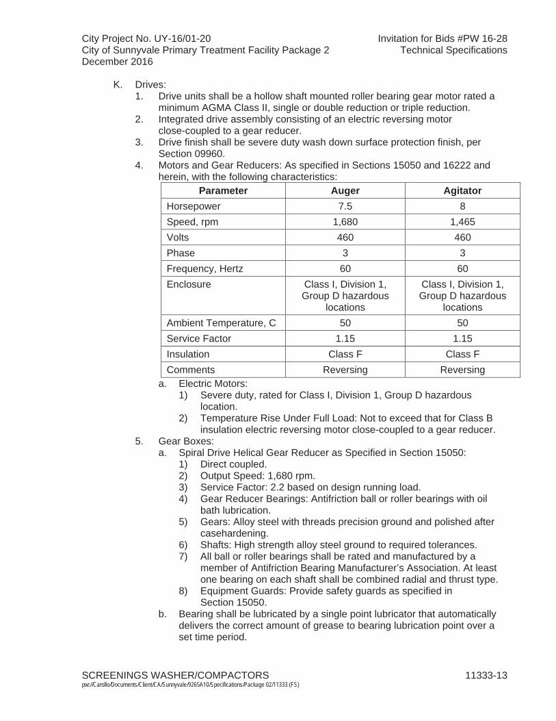
City Project No. UY-16/01-20 Invitation for Bids #PW 16-28City of Sunnyvale Primary Treatment Facility Package 2 Technical SpecificationsDecember 2016
SCREENINGS WASHER/COMPACTORS 11333-13pw://Carollo/Documents/Client/CA/Sunnyvale/9265A10/Specifications/Package 02/11333 (FS)
K. Drives:1. Drive units shall be a hollow shaft mounted roller bearing gear motor rated a
minimum AGMA Class II, single or double reduction or triple reduction.2. Integrated drive assembly consisting of an electric reversing motor
close-coupled to a gear reducer.3. Drive finish shall be severe duty wash down surface protection finish, per
Section 09960.4. Motors and Gear Reducers: As specified in Sections 15050 and 16222 and
herein, with the following characteristics:Parameter Auger Agitator
Horsepower 7.5 8 Speed, rpm 1,680 1,465Volts 460 460Phase 3 3 Frequency, Hertz 60 60Enclosure Class I, Division 1,
Group D hazardous locations
Class I, Division 1, Group D hazardous
locationsAmbient Temperature, C 50 50Service Factor 1.15 1.15Insulation Class F Class FComments Reversing Reversing
a. Electric Motors:1) Severe duty, rated for Class I, Division 1, Group D hazardous
location.2) Temperature Rise Under Full Load: Not to exceed that for Class B
insulation electric reversing motor close-coupled to a gear reducer. 5. Gear Boxes:
a. Spiral Drive Helical Gear Reducer as Specified in Section 15050:1) Direct coupled.2) Output Speed: 1,680 rpm.3) Service Factor: 2.2 based on design running load.4) Gear Reducer Bearings: Antifriction ball or roller bearings with oil
bath lubrication.5) Gears: Alloy steel with threads precision ground and polished after
casehardening.6) Shafts: High strength alloy steel ground to required tolerances.7) All ball or roller bearings shall be rated and manufactured by a
member of Antifriction Bearing Manufacturer’s Association. At least one bearing on each shaft shall be combined radial and thrust type.
8) Equipment Guards: Provide safety guards as specified in Section 15050.
b. Bearing shall be lubricated by a single point lubricator that automatically delivers the correct amount of grease to bearing lubrication point over a set time period.
City Project No. UY-16/01-20 Invitation for Bids #PW 16-28City of Sunnyvale Primary Treatment Facility Package 2 Technical SpecificationsDecember 2016
SCREENINGS WASHER/COMPACTORS 11333-14pw://Carollo/Documents/Client/CA/Sunnyvale/9265A10/Specifications/Package 02/11333 (FS)
L. Chutes:1. Screening Conveyor Discharge Chute:
a. Provide a new 12-gauge, Type 316 stainless steel discharge chute transitioning between the screening conveyor and Screening Washer/Compactor.
b. Submit discharge chute details for review and approval by Engineer.
M. Tipping troughs:1. Provide rotating U-shaped trough with a minimum diameter of 17 inches.2. Trough shall be open at the top.
a. Length of opening on the trough: As required to sufficiently fill the transport bin being used by haulers and as directed by the Engineer during construction.
3. The tipping trough end connected to the washer/compactor discharge pipe shall have a slide bearing made of HDPE.
4. The tipping trough assembly shall be supported by a support stand on each end of the trough as indicated in the Drawings.a. Support Stand Material: Type 316L stainless steel.
5. Provide three proximity sensors for the middle, left, and right position indication of the trough.
6. Drive Unit:a. Gear motor rated for continuous duty.b. The drive motor shall be 1 horsepower, suitable for a Class I, Division 1,
Group D hazardous locations Constant speed unit rotating at 1,750 rpm and shall be powered by 230/460 VAC, 60 HZ, 3-phase power.
c. The drive unit shall be direct coupled to the tipping trough drive shaft through the gear box.
N. Dewatering unit:1. An additional dewatering unit shall be mounted between the washer body
connection plate and discharge pipe.2. Length of dewatering unit shall not exceed 10 inches.3. The dewatering unit shall include 3-1/2-inch diameter flanged outlet in the
bottom section.4. The water supply line to the dewatering unit shall be provided with one 1-inch
diameter Burkert normally closed solenoid valve with maximum operating pressure of 140 psi.
2.04 CONTROLS
A. Manufacturer of the screenings washer compactor and tipping trough system shall provide local control panels and the associated controls necessary for fully automatic operation as shown on Drawings, as specified in Sections 16050, 17050, 17100, 17101, 17710, 17720, 17721, 17765, and 17950, and as recommended by equipment manufacturer to provide a complete operational system. Power to Control Panel shall be through a 480-volt, 3-phase, 60-Hertz feeder. The 480-volt load starters required to properly operate the screenings washer compactor and the tipping troughs will be located inside the vendor control panel. Provide step-down transformers inside the control panel to power the 120-volt loads.
City Project No. UY-16/01-20 Invitation for Bids #PW 16-28City of Sunnyvale Primary Treatment Facility Package 2 Technical SpecificationsDecember 2016
SCREENINGS WASHER/COMPACTORS 11333-15pw://Carollo/Documents/Client/CA/Sunnyvale/9265A10/Specifications/Package 02/11333 (FS)
B. Screenings washer/compactor local control stations (VCP2): 1. Enclosure:
a. Type NEMA 7 in accordance with Section 17710 with a hinged door for front access: 1) Cast aluminum.
b. Type: Rated for Class I, Division 2, Group D hazardous location.c. Electrical components shall be UL approved for use in the enclosure. The
control panel shall be UL approved and labeled.d. Manufacturer: One of the following or equal:
1) Rittal.2) Pentair (formerly Hoffman Engineering). 3) Saginaw Control & Engineering.
e. Latches:1) For panels, provide each door with a 3-point latching mechanism and
locking handle with rollers on the ends of the latch rods. Latch rods shall be connected to a common door handle, hold doors securely, and form a compressed seal between door and gasket, at the top, side, and bottom:a) Provide padlock for each enclosure with padlock provisions.
2. Control devices: a. EMERGENCY STOP maintained mushroom head pushbutton. b. Reset pushbutton.
C. Screenings tipping trough local control stations (VCP3): 1. Control devices:
a. EMERGENCY STOP maintained mushroom head pushbutton.
D. Vendor control panels (VCP1): 1. General:
a. Provide separate control panels for each washer/compactor unit thatprovides fully independent control. Include controls for each tipping trough in the control panel for the associated washer/compactor.
b. Control panel shall consist of, but not be limited to, the following to provide a complete and operable system:1) Preprogrammed PLC to control operation of the washer/compactor
and associated tipping trough that receives commands from the plant control system.a) PLC shall be manufactured by Allen-Bradley and conform to
specifications in Section 17720.2) Reversing magnetic starter with motor circuit protector disconnect.3) Hardwired interlocks to shut down the equipment in all modes of
operation and activates Fail Alarms upon any of the following conditions:a) Motor overload.b) High Temperature.
c. Control panel shall be located in an unclassified area.d. Control panel shall carry a UL label certifying the assembled industrial
control panel complies with UL 508.e. Control panel shall be completely prewired and factory tested for proper
operation prior to shipment. Refer to Section 17950 for additional testing requirements.
City Project No. UY-16/01-20 Invitation for Bids #PW 16-28City of Sunnyvale Primary Treatment Facility Package 2 Technical SpecificationsDecember 2016
SCREENINGS WASHER/COMPACTORS 11333-16pw://Carollo/Documents/Client/CA/Sunnyvale/9265A10/Specifications/Package 02/11333 (FS)
f. Communicate with the plant control system over DLR Ethernet/IP as shown on the control system block diagram.
g. Provide separate alarm and emergency shutdown functions.h. Provide local operator interface (LOI) unit for adjustment of setpoints,
timers, and alarms.2. Panel enclosure and components:
a. VCP enclosure type:1) NEMA 12 in accordance with Section 17710:
a) Steel with gasketed door, dust-tight.2) Enclosure shall be adequately sized and designed to dissipate heat
generated inside enclosure. Provide heating/cooling as specified in Section 17710 as needed.
3) Each VCP enclosure shall not exceed the following dimensions: 84-inches high by 48-inches wide by 24-inches deep.
4) Manufacturer: One of the following or equal:a) Rittal.b) Pentair (formerly Hoffman Engineering). c) Saginaw Control & Engineering.
5) Latches:a) For panels, provide each door with a 3-point latching
mechanism and locking handle with rollers on the ends of the latch rods. Latch rods shall be connected to a common door handle, hold doors securely, and form a compressed seal between door and gasket, at the top, side, and bottom:(1) Provide padlock for each enclosure with padlock provisions.
b. Components including enclosures shall conform to the requirements of Section 17710:1) Design controls such that the equipment cannot operate unless
controls are energized.2) Instruments mounted on the face of the panel and components
located within the panel shall meet the requirements specified in Section 17710.
3) Controls and instruments shall fail into a safe condition.4) Provide necessary interlocks and time delays (operator adjustable)
for system control.5) Indicators and alarms in accordance with Sections 17710 and 17101.
c. Power systems:1) Provide main circuit breaker flange-mounted power disconnect
interlocked to the enclosure door:a) VCP shall be labeled and rated to withstand the available fault
current as to be determined in the study per Section 16305.b) In accordance with Section 16412.
2) Provide surge protection device.3) Control voltage transformer for providing 120 VAC power to the
control circuit.d. Motor starters in accordance with Section 16422. e. Provide current monitoring on auger and agitator motors.f. Provide auxiliary contacts to energize washer/compactor motor winding
heaters when the equipment is not active.

City Project No. UY-16/01-20 Invitation for Bids #PW 16-28City of Sunnyvale Primary Treatment Facility Package 2 Technical SpecificationsDecember 2016
SCREENINGS WASHER/COMPACTORS 11333-17pw://Carollo/Documents/Client/CA/Sunnyvale/9265A10/Specifications/Package 02/11333 (FS)
g. Local Operator Interface (LOI) in accordance with Section 17721:1) NEMA 4X rated.2) 10-inch configurable color LCD touchscreen with a minimum
resolution of 640 by 480 pixels.3) 32 MB Flash EPROM Memory.
h. Programmable logic controller for automatic control of devices in accordance with Section 17720:1) Acceptable manufacturers, no equal:
a) Rockwell Automation:(1) ControlLogix.(2) CompactLogix.
2) The PLC programming software system shall be manufactured by PLC hardware manufacturer:a) Rockwell Software:
(1) RSLogix 5000.3) Central processing unit:
a) Configure each central processor unit so that it contains all the software relays, timers, counters, number storage registers, shift registers, sequencers, arithmetic capability, and comparators necessary to perform the specified control functions.
b) Capable of interfacing with all discrete inputs, analog inputs, discrete outputs, analog outputs and communication cards to meet the specified requirements.
c) Capable of supporting and implementing closed loop floating-point math and PID control that is directly integrated into the CPU control program.
4) 120 VAC Power Supply.5) Surge protection for all of the controls.6) Ethernet/IP Communications module (connection to LOI). 7) DLR Ethernet/IP Communications module (communication to
Owners Control system).8) 120 VAC Isolated Discrete Inputs (16 points max/module).9) 120 VAC Isolated Discrete Outputs (16 points max/module).10) 4-20 mA HART Analog Input module.11) Capable of utilizing a second Ethernet/IP module.12) Control Function in accordance with Section 17101.
i. Wiring:1) Factory assemble and wire the control panel such that field wiring
shall consist only of connections to terminals.2) Identify each end of each wire by a unique wire number printed on a
heat shrink sleeve marker.j. Provide Allen Bradley 1783-ETAP module for DLR network diagnostics.k. Pilot devices:
1) Pilot lights for: Refer to Section 17710 for pilot light colors.a) Control power on. b) Auger running.c) Auger not running.d) Agitator running.e) Agitator not running.f) Drain valve open.
City Project No. UY-16/01-20 Invitation for Bids #PW 16-28City of Sunnyvale Primary Treatment Facility Package 2 Technical SpecificationsDecember 2016
SCREENINGS WASHER/COMPACTORS 11333-18pw://Carollo/Documents/Client/CA/Sunnyvale/9265A10/Specifications/Package 02/11333 (FS)
g) Drain valve closed.h) Wash valve open. i) Tipping trough running.j) Auger fault. k) Agitator fault.l) Drain valve fault. m) Wash valve fault. n) Tipping trough fault.
2) Control devices:a) Agitator:
(1) H-O-A selector switch.(2) FORWARD-OFF-JOG REVERSE switch.
b) Auger:(1) H-O-A selector switch.(2) FORWARD-OFF-JOG REVERSE switch.
c) Drain valve:(1) H-O-A selector switch.(2) OPEN-CLOSE.
d) Wash water valve:(1) OPEN-CLOSE-AUTO selector switch.
e) Press zone spray valves:(1) OPEN-CLOSE-AUTO selector switch.
f) Drain pan spray valve:(1) OPEN-CLOSE-AUTO selector switch.
g) Wash Cycle Start software pushbutton.h) Wash Mode/Continuous Discharge Mode switch.i) Tipping Trough:
(1) LOCAL-OFF-REMOTE selector switch.(2) FORWARD-OFF-REVERSE selector switch. (3) Reset pushbutton.
3) Door mounted elapsed time meters for the following:a) Auger drive. b) Agitator drive.
4) Flashing alarm light and alarm horn with silencer-reset button: a) Plastic Nameplates.
l. Panel instruments as shown on the Drawings, as specified in Section 17710, and as recommended by the equipment manufacturer to provide a complete operational system.
3. Indicators, alarms and controls accessible through VCP Operator Interface Unit:a. Elapsed time meter.b. Alarm indication providing description of specific units.c. Timer set points.
4. Vendor equipment programming meetings: Attend a meeting with the Programmer to coordinate with the owners control system. The meeting discussion point will include the following at a minimum:a. Tag Naming Conventions.b. PLC to PLC global data mapping.c. All PLCs to HMI tags mapping.d. LOI screen colors and navigation.
City Project No. UY-16/01-20 Invitation for Bids #PW 16-28City of Sunnyvale Primary Treatment Facility Package 2 Technical SpecificationsDecember 2016
SCREENINGS WASHER/COMPACTORS 11333-19pw://Carollo/Documents/Client/CA/Sunnyvale/9265A10/Specifications/Package 02/11333 (FS)
e. Interlock and Permissive definitions.f. Communication Methods.g. Standard code blocks for common control functionality.h. Alarms – clearing, formats, colors, and status.
E. Inspection door switch:1. Enclosure:
a. Type: Rated for Class I, Division 2, Group D hazardous location.
F. Operation:1. Washer/compactor and tipping trough operation shall be controlled by the
vendor control panel.2. Reference Section 17101 for equipment and system operation requirements.
2.05 FINISHES
A. Surface preparation, factory prime, field prime, and finish coats as specified in Section 09960.
2.06 SOURCE QUALITY CONTROL
A. Factory testing:1. The compactors shall be factory assembled and tested before shipment.2. Manufacturer shall perform Source Quality Control Testing per Section 15958,
and as herein described:a. Equipment Performance Test Level: 1, non-witnessed.b. Vibration Test Level: 1, non-witnessed.c. Noise Test Level: N/A.
3. Operate compactor to verify proper operation of the unit and all controls.
PART 3 EXECUTION
3.01 INSTALLATION
A. Equipment shall be installed in strict conformance with the manufacturer’s installation instructions.
3.02 FIELD QUALITY CONTROL
A. Contractor and manufacturer shall jointly perform Field Quality Control Testing per Section 15958, and as described herein:1. Equipment Performance Test Level: 1.2. Vibration Test Level: 1.3. Noise Test Level: N/A.
B. Verify conformance with the specified Equipment Design Criteria:1. Screenings washing capacity.2. Screenings throughput capacity.3. Functionality of all controls including control panel, level monitoring system,
overloads, and all modes of operation.
C. Refer to Sections 16950 and 17950 for additional requirements.
City Project No. UY-16/01-20 Invitation for Bids #PW 16-28City of Sunnyvale Primary Treatment Facility Package 2 Technical SpecificationsDecember 2016
SCREENINGS WASHER/COMPACTORS 11333-20pw://Carollo/Documents/Client/CA/Sunnyvale/9265A10/Specifications/Package 02/11333 (FS)
3.03 MANUFACTURER’S FIELD SERVICES
A. Coordinate field service work with the manufacturer’s representative, Owner, and Engineer prior to initiating such work.
B. Require manufacturer’s representative to perform the following services in a minimum of two separate trips as described below and as specified in Section 01756. Specified durations are the minimum required time on the job site. Additional services and/or longer durations shall be provided as needed at no cost to Owner to meet the required quality of work:1. Installation Inspection and Assistance: One trip. 2 workdays each trip:
a. Advise/observe Contractor on installation of the compactors.b. Check and verify that installation of the compactors is in accordance with
the Drawings and manufacturer’s installation instructions.c. Inspect equipment installation and make any necessary adjustments.
2. Certification of installation, field testing, and start-up assistance: 3 workdays:a. Prior to startup, the equipment shall be inspected for proper alignment,
operation, and satisfactory performance.b. Require manufacturer’s representative to complete all certificates, reports,
and forms in Section 01756. 3. Training: As defined in Specification Section 01756. Provide training as
follows:a. Operations Training: 6 hours, presented twice, for a total of 12 hours.b. Mechanical Maintenance Training: 6 hours, presented twice, for a total of
12 hours.c. Electrical and Controls Maintenance Training: 2 hours of training,
presented twice, for a total of 4 hours.4. Final Acceptance Checkout: 1 workday.5. Post Start-up Checkout: 1 workday.6. Each workday consists of 8 working hours.7. Specified durations are the minimum required time on job site and do not
include travel time.
C. Provide services of a factory-trained Service Technician, specifically trained on the type of equipment specified. Service Engineer requirements include, but are not limited to the following:1. Service Technician must be present as described in Article 3.02. Man-hours
on site are exclusive of travel time and do not relieve Contractor of the obligation to place equipment in operation as specified.
2. Inspect and verify location of anchor bolts, placement, leveling, alignment, and field erection of equipment, as well as control panel operation and electrical connections and at the installation.
3. Provide classroom and/or field training on equipment operation and maintenance to operating personnel. These instructions may include use of slides, videos, literature, and/or oral presentations.
D. In the event that the field service time required by this Section is not sufficient to properly place equipment into operation, additional time shall be arranged by Contractor to correct deficiencies in installation, equipment, or material without additional cost to Owner.
City Project No. UY-16/01-20 Invitation for Bids #PW 16-28City of Sunnyvale Primary Treatment Facility Package 2 Technical SpecificationsDecember 2016
SCREENINGS WASHER/COMPACTORS 11333-21pw://Carollo/Documents/Client/CA/Sunnyvale/9265A10/Specifications/Package 02/11333 (FS)
3.04 MANUFACTURER’S MAINTENANCE CONTRACT
A. Provide maintenance contract to provide the following services for 3 years: 1. Visit equipment once a year for 4 days including travel. Coordinate visit dates
with the Owner. 2. Inspect equipment and perform annual procedure identified in maintenance
schedule.3. Perform the following routine wear item replacements when necessary based
on inspection during site visit: a. New brush. b. Set of spiral wear shoes.
END OF SECTION

City Project No. UY-16/01-20 Invitation for Bids #PW 16-28City of Sunnyvale Primary Treatment Facility Package 2 Technical SpecificationsDecember 2016
SCREENINGS WASHER/COMPACTORS 11333-Appendix Apw://Carollo/Documents/Client/CA/Sunnyvale/9265A10/Specifications/Package 02/11333 (FS)
Section 11333 – Screenings Washer/Compactors
APPENDIX A - PRE-NEGOTIATED PROPOSAL FOR SCREENINGS WASHER/COMPACTORS


Rev. 4: 9-12-16
FIRM PROPOSAL
City Project No. UY-16/01-20 City of Sunnyvale Primary Treatment Facility Package 2 December 2016
Invitation for Bids #PW 16-28. Technical Specifications
SCREENINGS WASHER/COMPACTORS 11333-Appendix Apw://Carollo/Documents/Client/CA/Sunnyvale/9265A10/Specifications/Package 02/11333_Appendix_A1 (FS)
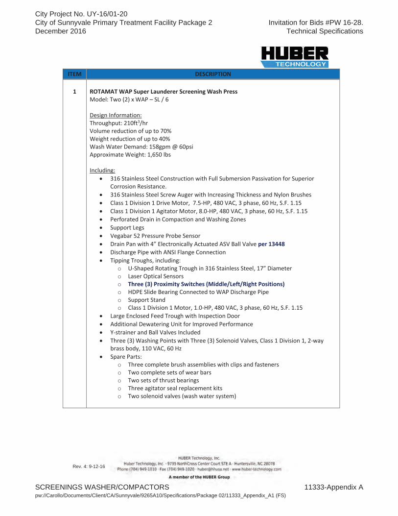
Rev. 4: 9-12-16
o o o o o o
o o o o o
City Project No. UY-16/01-20 City of Sunnyvale Primary Treatment Facility Package 2 December 2016
Invitation for Bids #PW 16-28. Technical Specifications
SCREENINGS WASHER/COMPACTORS 11333-Appendix Apw://Carollo/Documents/Client/CA/Sunnyvale/9265A10/Specifications/Package 02/11333_Appendix_A1 (FS)

Rev. 4: 9-12-16
· ·
City Project No. UY-16/01-20 City of Sunnyvale Primary Treatment Facility Package 2 December 2016
Invitation for Bids #PW 16-28. Technical Specifications
SCREENINGS WASHER/COMPACTORS 11333-Appendix Apw://Carollo/Documents/Client/CA/Sunnyvale/9265A10/Specifications/Package 02/11333_Appendix_A1 (FS)

Rev. 4: 9-12-16
City Project No. UY-16/01-20 City of Sunnyvale Primary Treatment Facility Package 2 December 2016
Invitation for Bids #PW 16-28. Technical Specifications
SCREENINGS WASHER/COMPACTORS 11333-Appendix Apw://Carollo/Documents/Client/CA/Sunnyvale/9265A10/Specifications/Package 02/11333_Appendix_A1 (FS)
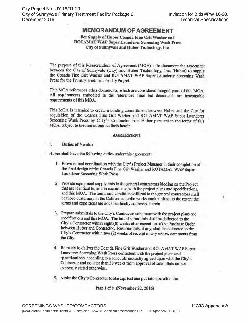
City Project No. UY-16/01-20City of Sunnyvale Primary Treatment Facility Package 2December 2016
Invitation for Bids #PW 16-28.Technical Specifications
11333-Appendix A
City Project No. UY-16/01-20 City of Sunnyvale Primary Treatment Facility Package 2 December 2016
Invitation for Bids #PW 16-28. Technical Specifications
SCREENINGS WASHER/COMPACTORS 11333-Appendix Apw://Carollo/Documents/Client/CA/Sunnyvale/9265A10/Specifications/Package 02/11333_Appendix_A2 (FS)

City Project No. UY-16/01-20 City of Sunnyvale Primary Treatment Facility Package 2 December 2016
Invitation for Bids #PW 16-28. Technical Specifications
SCREENINGS WASHER/COMPACTORS 11333-Appendix Apw://Carollo/Documents/Client/CA/Sunnyvale/9265A10/Specifications/Package 02/11333_Appendix_A2 (FS)

City Project No. UY-16/01-20City of Sunnyvale Primary Treatment Facility Package 2December 2016
Invitation for Bids #PW 16-28.Technical Specifications
SCREENINGS WASHER/COMPACTORS 11333-Appendix Apw://Carollo/Documents/Client/CA/Sunnyvale/9265A10/Specifications/Package 02/11333_Appendix_A1 (FS)
City Project No. UY-16/01-20 City of Sunnyvale Primary Treatment Facility Package 2 December 2016
Invitation for Bids #PW 16-28. Technical Specifications
SCREENINGS WASHER/COMPACTORS 11333-Appendix Apw://Carollo/Documents/Client/CA/Sunnyvale/9265A10/Specifications/Package 02/11333_Appendix_A2 (FS)
City Project No. UY-16/01-20 City of Sunnyvale Primary Treatment Facility Package 2 December 2016
Invitation for Bids #PW 16-28. Technical Specifications
SCREENINGS WASHER/COMPACTORS 11333-Appendix Apw://Carollo/Documents/Client/CA/Sunnyvale/9265A10/Specifications/Package 02/11333_Appendix_A2 (FS)
City Project No. UY-16/01-20 City of Sunnyvale Primary Treatment Facility Package 2 December 2016
Invitation for Bids #PW 16-28. Technical Specifications
SCREENINGS WASHER/COMPACTORS 11333-Appendix Apw://Carollo/Documents/Client/CA/Sunnyvale/9265A10/Specifications/Package 02/11333_Appendix_A2 (FS)
City Project No. UY-16/01-20 City of Sunnyvale Primary Treatment Facility Package 2 December 2016
Invitation for Bids #PW 16-28. Technical Specifications
SCREENINGS WASHER/COMPACTORS 11333-Appendix Apw://Carollo/Documents/Client/CA/Sunnyvale/9265A10/Specifications/Package 02/11333_Appendix_A2 (FS)

City Project No. UY-16/01-20 City of Sunnyvale Primary Treatment Facility Package 2 December 2016
Invitation for Bids #PW 16-28. Technical Specifications
SCREENINGS WASHER/COMPACTORS 11333-Appendix Apw://Carollo/Documents/Client/CA/Sunnyvale/9265A10/Specifications/Package 02/11333_Appendix_A2 (FS)
City Project No. UY-16/01-20 City of Sunnyvale Primary Treatment Facility Package 2 December 2016
Invitation for Bids #PW 16-28. Technical Specifications
SCREENINGS WASHER/COMPACTORS 11333-Appendix Apw://Carollo/Documents/Client/CA/Sunnyvale/9265A10/Specifications/Package 02/11333_Appendix_A2 (FS)
City Project No. UY-16/01-20 City of Sunnyvale Primary Treatment Facility Package 2 December 2016
Invitation for Bids #PW 16-28. Technical Specifications
SCREENINGS WASHER/COMPACTORS 11333-Appendix Apw://Carollo/Documents/Client/CA/Sunnyvale/9265A10/Specifications/Package 02/11333_Appendix_A2 (FS)
City Project No. UY-16/01-20 City of Sunnyvale Primary Treatment Facility Package 2 December 2016
Invitation for Bids #PW 16-28. Technical Specifications
SCREENINGS WASHER/COMPACTORS 11333-Appendix Apw://Carollo/Documents/Client/CA/Sunnyvale/9265A10/Specifications/Package 02/11333_Appendix_A2 (FS)
City Project No. UY-16/01-20 Invitation for Bids #PW 16-28City of Sunnyvale Primary Treatment Facility Package 2 Technical SpecificationsDecember 2016
ROTARY-LOBE BLOWERS 11376A-1 pw://Carollo/Documents/Client/CA/Sunnyvale/9265A10/Specifications/Package 02/11376A (FS)
SECTION 11376A
ROTARY-LOBE BLOWERS
PART 1 GENERAL
1.01 SUMMARY
A. Section includes: Channel air agitation blowers, blower panel, and appurtenancesfor the primary influent distribution channel: 1. Equipment List:
a. Blower No. 1 - BLO 241.601. b. Blower No. 2 - BLO 241.602.
B. Related sections: 1. The Contract Documents are complementary; what is called for by one is as
binding as if called for by all.2. It is the Contractor’s responsibility for scheduling and coordinating the Work of
subcontractors, suppliers, and other individuals or entities performing or furnishing any of Contractor’s Work.
3. The following Sections are related to the Work described in this Section. This list of Related Sections is provided for convenience only and is not intended to excuse or otherwise diminish the duty of the Contractor to see that the completed Work complies accurately with the Contract Documents:a. Section 01010 - Summary of Work.b. Section 01340 - Shop Drawings, Product Data and Samples.c. Section 01610 - Project Design Criteria.d. Section 01612 - Seismic Design Criteria.e. Section 01614 - Wind Design Criteria.f. Section 01756 - Commissioning and Process Start-Up. g. Section 01730 - Operation and Maintenance Data.h. Section 05190 - Mechanical Anchoring and Fastening to Concrete and
Masonry.i. Section 09960 - High-Performance Coatings. j. Section 13446 - Manual Actuators. k. Section 13448 - Intelligent Actuators.l. Section 15050 - Common Work Results for Mechanical Equipment.m. Section 15082 - Piping Insulation.n. Section 15117 - Specialty Valves.o. Section 16222 - Low Voltage Motors up to 500 Horsepower.p. Section 17101 - Specific Control Strategies.
1.02 REFERENCES
A. American Iron and Steel Institute (AISI).
B. American National Standards Institute (ANSI).
City Project No. UY-16/01-20 Invitation for Bids #PW 16-28City of Sunnyvale Primary Treatment Facility Package 2 Technical SpecificationsDecember 2016
ROTARY-LOBE BLOWERS 11376A-2 pw://Carollo/Documents/Client/CA/Sunnyvale/9265A10/Specifications/Package 02/11376A (FS)
C. American Petroleum Institute (API):1. 617 - Rotary Assembly Dynamic Balancing.
D. American Society of Mechanical Engineers (ASME):1. ASME PTC 10 - Performance Test Code - Compressors and Exhausters.
E. American Bearing Manufacturers Association (ANSI/ABMA):1. 9 - Load Ratings and Fatigue Life for Ball Bearings.2. 11 - Load Ratings and Fatigue Life for Roller Bearings.
F. Institute of Electrical and Electronics Engineers (IEEE):1. 85 - Test Procedure for Airborne Noise Measurements on Rotating Electric
Machinery.
1.03 DEFINITIONS
A. Continuous Operation: 24-hours per day operation for design life of not less than 20 years, or 175,200 hours.
B. Intermittent Operation: Periodic operation, including starts and stops; including extended periods of time when not in use.
C. Rotary Blower System: The blower unit, including but not limited to: Rotary blower, motor, controls, and all appurtenances including, but not limited to, inlet and discharge silencers, required to furnish a complete packaged installation as specified herein and as indicated on the plans.
1.04 SYSTEM DESCRIPTION
A. The channel air agitation blowers will supply air to the primary influent distribution channel to keep solids in suspension. Under normal operation, the blowers will run at full speed. Operator will have flexibility to run blowers at set blower speed or set flow rate.
B. General: Channel air agitation blowers and appurtenances shall include the following items supplied by blower manufacturer:1. Rotary Positive Displacement Blower, Motor and Variable Frequency Drive
(VFD). 2. Air intake filters.3. Silencers, inlet, discharge, and vent.4. Blowoff circuit.5. Check valves.6. Relief valves.7. Flexible pipe connectors.8. Sound Enclosure.9. Appurtenances as required.

City Project No. UY-16/01-20 Invitation for Bids #PW 16-28City of Sunnyvale Primary Treatment Facility Package 2 Technical SpecificationsDecember 2016
ROTARY-LOBE BLOWERS 11376A-3 pw://Carollo/Documents/Client/CA/Sunnyvale/9265A10/Specifications/Package 02/11376A (FS)
C. Design requirements:Parameter Value
Type of Blower Rotary lobe, positive displacement
Number of blowers 2 (1 duty + 1 standby)
Rated speed 4,800 revolutions per minute (rpm), maximum
Maximum inlet air flow at rated speed 950 scfm
Minimum inlet air flow 225 scfm
Inlet filter pressure loss 0.20 pounds per square inch
Rated relative humidity 100% RH
Rated barometer 14.7 psia
Rated Inlet temperature 97 degrees Fahrenheit
Rated discharge pressure 4.5 psig1. Motor: As specified in Section 16222, except as otherwise specified or
supplemented below:a. Provide winding temperature switches or PTC thermisters. b. Provide motor winding space heater:
Power supply 480 volt, 3 phase, 60 hertz
Horsepower 40
Speed VFD, 4,800 rpm (maximum)
Enclosure TEFC
Service factor 1.152. Drive: The blower shall be V-belt driven with the drive designed for a minimum
140 percent of motor hp, and include an adjustable motor slide base or swing base. Sheaves shall be two part, with taper lock style attachment to the shaft.Sheaves shall be dynamically balanced as required by the manufacturer’s maximum rim speed. V-belt design shall calculate the forces on the blower input drive shaft and motor so as not to exceed maximum bearing side load. A totally enclosed guard built to OSHA specifications shall be painted safety yellow. In lieu of V-Belt Drive, a direct couple between the blower and drive motor may be acceptable, with no changes to the basic mechanical layout allowed. Direct couple shall be “S-Flex” style, two-piece EPMD with retaining ring (E-Type), with a 1.5 service factor manufactured by Lovejoy or approved equal.
3. Provide controls as indicated on the P&ID Drawings and as specified in Section 17100.
D. Operations Description, Monitoring, and Alarms: As indicated on the P&ID Drawings and as specified in Section 17100 and Section 17101.

City Project No. UY-16/01-20 Invitation for Bids #PW 16-28City of Sunnyvale Primary Treatment Facility Package 2 Technical SpecificationsDecember 2016
ROTARY-LOBE BLOWERS 11376A-4 pw://Carollo/Documents/Client/CA/Sunnyvale/9265A10/Specifications/Package 02/11376A (FS)
1.05 SUBMITTALS
A. Product data and shop drawings: Include:1. Blower panel device layout and material list.2. Literature and drawings describing equipment performance and construction in
sufficient detail, including parts list, dimensions, materials, and details of construction and installation.
3. Schematic electrical wiring diagrams and other data as required for complete system.
4. Certified dimensional data for components, including foundation and anchor bolts and details.
5. Equipment Data:a. Blower Information:
1) Manufacturer.2) Model.3) Blower speed in revolutions per minute.4) Blower site capacity, actual cubic feet per minute.5) Discharge pressure, psia.6) Horsepower required including loss in V-belt drive.7) Weight of blower.8) Weight of motor.9) Free-field noise level at 3 feet from blower acoustic enclosure.
b. Motor performance and construction data including VFD. c. Descriptive brochures and applicable performance and construction data
for each item of auxiliary equipment along with their weights.
B. Furnish motor submittals as specified in Section 16222.
C. Manufacturer’s Representative's qualifications as specified in Section 01756.
D. Provide vendor operation and maintenance manual as specified in Section 01730.
1.06 QUALITY ASSURANCE
A. Manufacturer qualifications:1. Minimum 15 years' experience in manufacturing similar equipment utilized in
water and wastewater treatment plants.2. Supplies accessories including motor.3. Assumes responsibility for compatibility of components furnished.4. Furnishes services of factory representatives with complete knowledge of
proper installation, operation, and maintenance of equipment to inspect and approve final installation and supervise test runs of equipment.
B. Package system shall be supplied by the blower manufacturer. Verification to be part of shop drawing review.
C. Equipment supplier must have a service facility within (200) miles of job site.
D. Manufacture’s Certificate of Installation and Functionality Compliance as specified in Section 01756.
City Project No. UY-16/01-20 Invitation for Bids #PW 16-28City of Sunnyvale Primary Treatment Facility Package 2 Technical SpecificationsDecember 2016
ROTARY-LOBE BLOWERS 11376A-5 pw://Carollo/Documents/Client/CA/Sunnyvale/9265A10/Specifications/Package 02/11376A (FS)
1.07 ENVIRONMENTAL CONDITIONS
A. Environmental requirements: As specified in Section 01610.
B. Blower shall be suitable for continuous service and intermittent operations.
C. Site conditions for determining rated ACFM noted in Article 1.02 Paragraph B Design Requirements.
1.08 WARRANTY
A. Provide a manufacturer’s warranty meeting the requirements of Section 01740.
1.09 SPARE PARTS
A. Furnish one set of special tools with equipment when required for normal operation and maintenance.
B. Spare Parts: Include:1. 4 complete sets of ventilation and air intake filters.2. 2 sets of drive belts or direct couplings.
C. Label spare parts as specified in Section 15050 and box for storage.
PART 2 PRODUCTS
2.01 BLOWERS
A. Manufacturers: One of the following, modified as necessary to meet the Specification requirements: 1. Aerzen, Generation 5 Delta Blower Package.2. Kaeser Compressors, Com-paK Plus. 3. Or approved equal.
2.02 MATERIALS
A. General:1. Channel Air Agitation Blower Package Assembly: Complete with sound
attenuating enclosure, blower, drive, inlet and discharge silencers, valves, and appurtenances.
2. Blower Rating: As specified above.3. Rotation direction of blower shall match requirements of piping.
B. Blower and drive:1. General:
a. Blower shall deliver oil-free air.b. Blower and Motor Mounting: On common base.

City Project No. UY-16/01-20 Invitation for Bids #PW 16-28City of Sunnyvale Primary Treatment Facility Package 2 Technical SpecificationsDecember 2016
ROTARY-LOBE BLOWERS 11376A-6 pw://Carollo/Documents/Client/CA/Sunnyvale/9265A10/Specifications/Package 02/11376A (FS)
c. Lifting Provisions: Lifting eyes on blowers, motors, and base so each major component or entire unit can be lifted.
d. Piping Connections: 125 pound class flanges meeting ANSI B16.1.2. Type: Positive displacement rotary blowers using 2 impellers to pressurize a
trapped volume of air at a controlled rate prior to exposing it to a discharge pressure.
3. Casing and Head Plates:a. Blower Casing: One piece with separate head plates and end covers.b. Casing and Head Plates: Made of close-grained, machined cast iron.c. End Covers and Head Plates: Reinforced with bosses at penetrations with
cast, machined support feet.d. Housing: Feedback plenum on the discharge port that bleeds back some
of the discharge air to a closed pocket as the rotor tip passes to reduce pulsation and noise.
4. Impellers:a. Material: Ductile iron or cast iron, ASTM A48 Class 30B or steel AISI
1045. b. Design: Straight, 2-lobe or 3-lobe, involute type.c. Balance: Statically and dynamically, by removing metal from impeller
body.d. Operation: Free of rubbing without need for liquid seals or lubrication.e. Timing: Positively by a pair of accurately machined, heat treated, alloy
steel timing gears. Helical gears shall be machined from hardened alloy steel and bolted to timing hubs. Timing hubs shall be serrated on the inner diameter and placed over matching serrations on the shaft. Timing gears and hubs shall be locked in the axial position by a lock nut to assure no slippage.
f. Shafts: Alloy steel forgings, one piece impeller design. g. Impeller Assembly Support: Anti-friction type bearings, sized for a
minimum ABMA L-10 life of 100,000 hours.5. Lubrication:
a. Positive Oil Seal: Provided at each bearing.b. Seal Design: Capable of preventing lubricant from leaking into air stream.c. Vent Provisions: Capable of venting impeller side of oil seal to
atmosphere while eliminating possible carryover of lubricant into air stream.
d. Drive-end Bearings: Splash oil lubricated from an oil reservoir in the drive end cover housing.
e. Timing Gears and Gear-end Bearings: Splash oil lubricated from an oil reservoir in the drive end cover housing.
f. Blowers Shipment: With openings sealed after injection of rust inhibitor.
2.03 APPURTENANCES
A. Inlet air filter/silencer: 1. Provide filter/silencer installed at the blower inlet connection inside enclosure. 2. Galvanized Carbon Steel housing with front access for paper or pleated filter
elements and suitable clamps.3. MERV rating of 50 - 70 percent and can achieve removal efficiency of 3 micron
particle size and larger.
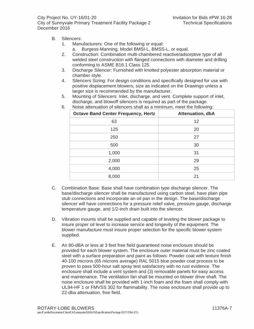
City Project No. UY-16/01-20 Invitation for Bids #PW 16-28City of Sunnyvale Primary Treatment Facility Package 2 Technical SpecificationsDecember 2016
ROTARY-LOBE BLOWERS 11376A-7 pw://Carollo/Documents/Client/CA/Sunnyvale/9265A10/Specifications/Package 02/11376A (FS)
B. Silencers:1. Manufacturers: One of the following or equal:
a. Burgess-Manning, Model BMSI-L, BMSS-L, or equal. 2. Construction: Combination multi-chambered reactive/adsorptive type of all
welded steel construction with flanged connections with diameter and drilling conforming to ASME B16.1 Class 125.
3. Discharge Silencer: Furnished with knotted polyester absorption material or chamber style.
4. Silencers Sizing: For design conditions and specifically designed for use with positive displacement blowers, size as indicated on the Drawings unless a larger size is recommended by the manufacturer.
5. Mounting of Silencers: Inlet, discharge, and vent. Complete support of inlet, discharge, and blowoff silencers is required as part of the package.
6. Noise attenuation of silencers shall as a minimum, meet the following:Octave Band Center Frequency, Hertz Attenuation, dbA
63 12
125 20
250 27
500 30
1,000 31
2,000 29
4,000 25
8,000 21
C. Combination Base: Base shall have combination type discharge silencer. The base/discharge silencer shall be manufactured using carbon steel, have plain pipe stub connections and incorporate an oil pan in the design. The base/discharge silencer will have connections for a pressure relief valve, pressure gauge, discharge temperature gauge, and 1/2-inch drain built into the silencer.
D. Vibration mounts shall be supplied and capable of leveling the blower package to insure proper oil level to increase service and longevity of the equipment. The blower manufacture must insure proper selection for the specific blower system supplied.
E. An 80-dBA or less at 3 feet free field guaranteed noise enclosure should be provided for each blower system. The enclosure outer material must be zinc coated steel with a surface preparation and paint as follows: Powder coat with texture finish 40-100 microns (65 microns average) RAL 5015 blue powder coat process to be proven to pass 500-hour salt spray test satisfactory with no rust evidence. The enclosure shall include a vent system and (3) removable panels for easy access and maintenance. The ventilation fan shall be mounted on blower drive shaft. The noise enclosure shall be provided with 1-inch foam and the foam shall comply withUL94-HF 1 or FMVSS 302 for flammability. The noise enclosure shall provide up to 22-dba attenuation, free field.
City Project No. UY-16/01-20 Invitation for Bids #PW 16-28City of Sunnyvale Primary Treatment Facility Package 2 Technical SpecificationsDecember 2016
ROTARY-LOBE BLOWERS 11376A-8 pw://Carollo/Documents/Client/CA/Sunnyvale/9265A10/Specifications/Package 02/11376A (FS)
F. Relief valve: Spring type, full-nozzle type; sized to relieve full blower capacity with 10 percent accumulation; 10 pounds per square inch gauge set pressure. Relief valve outlet shall be steel body with aluminum cover, screwed, or flanged connections per ANSI B16.
G. Butterfly valves:1. Constructed as specified in Sections 15112, 13446, and 13448. 2. Lined with 10 mils of epoxy suitable for temperatures to
280 degrees Fahrenheit.3. Sealed with EPDM seals suitable for temperatures of 280 degrees Fahrenheit.4. Provide where shown or required for blowoff circuit.
H. Check valves: Flapper type; consisting of following components:1. 2. Valve body and disc: Carbon Steel or ASTM A536 Ductile iron. 3. Seat: 304 SS, ASTM A276. 4. Disc arm and external levers: Ductile iron. 5. Seals, EPDM rated for minimum 280 degrees Fahrenheit.
I. Pressure gauges as specified per Section 17404.
J. Inlet filter differential pressure gauges as specified per Section 17404.
K. Temperature gauges: As specified per Section 17602.
L. Switches: Provide the following switches mounted on the blower inside of enclosure as part of the package:1. High Discharge Air Temperature Switch:
a. With thermowell, suitable for direct or remote mounting in discharge piping.
b. Adjustable over range of 80 to 300 degrees Fahrenheit or as recommended by blower manufacturer. Initial setting as recommended by blower manufacturer.
c. NEMA 4. 2. High Discharge Air Pressure Switch:
a. Range as recommended by blower manufacturer: initial setting as recommended by bower manufacturer.
b. NEMA 4.3. High Inlet Filter Vacuum Switch:
a. Range as recommended by blower manufacturer: initial setting as recommended by bower manufacturer.
b. NEMA 4.4. Motor Winding Temperature Switch or PTC thermister:
a. Range as recommended by blower manufacturer: initial setting as recommended by bower manufacturer.
b. NEMA 4.
M. Other Safety Devices and Controls: As recommended by blower manufacturer.
City Project No. UY-16/01-20 Invitation for Bids #PW 16-28City of Sunnyvale Primary Treatment Facility Package 2 Technical SpecificationsDecember 2016
ROTARY-LOBE BLOWERS 11376A-9 pw://Carollo/Documents/Client/CA/Sunnyvale/9265A10/Specifications/Package 02/11376A (FS)
N. Rubber expansion joints:1. Provided at inlet and discharge flanges of blowers.2. Suitable for pressures up to 15 pounds per square inch gauge and
temperature up to 280 degrees Fahrenheit.3. Manufacturers: One of the following or equal:
a. General Rubber, or equal.
O. Discharge Piping and Silencer Insulation: As specified in Section 15082, and as indicated on the Drawings.
P. Supports and Bracing: As required to support blower, associated equipment, andpiping, and to prevent excessive or harmful vibration or movement of equipment or piping.
2.04 CONTROL SYSTEM
A. Provide a complete fully functional control system for operation of the aeration blower.
B. Vendor control panel:1. General:
a. Provide separate control panels for each aeration blower that provides fully independent control.
b. Control panel shall consist of, but not be limited to, the following to providea complete and operable system:1) Preprogrammed PLC to control operation of the aeration blower that
receives commands from the plant control system: a) PLC shall be manufactured by Allen-Bradley and conform to
specifications in Section 17720.2) Variable frequency drive (VFD) with motor circuit protector
disconnect.3) Hardwired interlocks to shut down the equipment in all modes of
operation and activates Fail Alarms upon any of the following conditions:a) Motor overload.b) High Temperature.
c. Control panel shall carry a UL label certifying the assembled industrial control panel complies with UL 508.
d. Control panel shall be completely prewired, preprogrammed, and factory tested for proper operation prior to shipment. Refer to Section 17950 for additional testing requirements.
e. Communicate with the plant control system over DLR Ethernet/IP as shown on the control system block diagram.
f. Provide separate alarm and emergency shutdown functions.2. Panel enclosure and components:
a. VCP enclosure type:1) Floor-mount with hinged doors for front access as specified in
Section 17710.2) The VCP enclosure shall be adequately sized and designed to
dissipate the heat generated inside the enclosure. Provide a fan kit as specified in Section 17710 as needed.
City Project No. UY-16/01-20 Invitation for Bids #PW 16-28City of Sunnyvale Primary Treatment Facility Package 2 Technical SpecificationsDecember 2016
ROTARY-LOBE BLOWERS 11376A-10pw://Carollo/Documents/Client/CA/Sunnyvale/9265A10/Specifications/Package 02/11376A (FS)
3) Each VCP enclosure shall not exceed the following dimensions: 84 inches high by 72 inches wide by 36 inches deep.
4) Manufacturer: One of the following or equal:a) Rittal.b) Pentair (formerly Hoffman Engineering). c) Saginaw Control & Engineering.
5) Latches:a) For panels, provide each door with a 3-point latching
mechanism and locking handle with rollers on the ends of the latch rods. Latch rods shall be connected to a common door handle, hold doors securely, and form a compressed seal between door and gasket, at the top, side, and bottom:(1) Provide padlock for each enclosure with padlock provisions.
b. Components including enclosures shall conform with requirements of Section 17710:1) Design controls such that the equipment cannot operate unless
controls are energized.2) Instruments mounted on the face of the panel and components
located within the panel shall meet the requirements specified in Section 17710.
3) Controls and instruments shall fail into a safe condition.4) Provide necessary interlocks and time delays (operator adjustable)
for system control.5) Indicators and Alarms in accordance with Sections 17710 and 17101.
c. Power systems:1) Power supply to panel: 480-volt, 60-Hz, 3-phase.2) Provide main circuit breaker flange-mounted power disconnect
interlocked to the enclosure door:a) VCP shall be labeled and rated to withstand the available fault
current as to be determined in the study per Section 16305.b) In accordance with Section 16412.
3) Provide surge protection device.d. VFD as manufactured by Allen Bradley to match Owner standard. e. Programmable logic controller for automatic control of devices in
accordance with Section 17720:1) Acceptable manufacturers, no equal:
a) Rockwell Automation:(1) ControlLogix.(2) CompactLogix.
2) The PLC programming software system shall be manufactured by PLC hardware manufacturer:a) Rockwell Software:
(1) RSLogix 5000.3) Central processing unit:
a) Configure each central processor unit so that it contains all the software relays, timers, counters, number storage registers, shift registers, sequencers, arithmetic capability, and comparators necessary to perform the specified control functions.
City Project No. UY-16/01-20 Invitation for Bids #PW 16-28City of Sunnyvale Primary Treatment Facility Package 2 Technical SpecificationsDecember 2016
ROTARY-LOBE BLOWERS 11376A-11pw://Carollo/Documents/Client/CA/Sunnyvale/9265A10/Specifications/Package 02/11376A (FS)
b) Capable of interfacing with all discrete inputs, analog inputs, discrete outputs, analog outputs and communication cards to meet the specified requirements.
c) Capable of supporting and implementing closed loop floating-point math and PID control that is directly integrated into the CPU control program.
4) 120 VAC Power Supply.5) Surge protection for all of the controls. 6) DLR Ethernet/IP Communications module (communication to
Owners Control system).7) 120 VAC Isolated Discrete Inputs (16 points max/module).8) 120 VAC Isolated Discrete Outputs (16 points max/module).9) 4-20 mA HART Analog Input module.10) Capable of utilizing a second Ethernet/IP module.11) Control Function in accordance with Section 17101.
f. Wiring:1) Factory assemble and wire the control panel such that field wiring
shall consist only of connections to terminals.2) Identify each end of each wire by a unique wire number printed on a
heat shrink sleeve marker.g. Provide Allen Bradley 1783-ETAP module for DLR network diagnostics.h. Panel instruments as shown on the Drawings, as specified in
Section 17710, and as recommended by the equipment manufacturer to provide a complete operational system.
3. Indicators, alarms, and controls accessible through VCP Operator Interface Unit:a. Elapsed time meter.b. Alarm indication providing description of specific faults.
4. Provide contacts rated for 10A at 120VAC for remote monitoring of the status signals listed in Section 17101.
5. Data to transmit to the Owner’s control system over Ethernet/IP:a. Aeration Blower Overview:
1) Operation Status. 2) Motor Status. 3) Control Selection (REMOTE/LOCAL).
b. Alarm Management: 1) List of Active Alarms.
6. Vendor equipment programming meetings: Attend a meeting with the Programmer to coordinate with the owners control system. The meeting discussion point will include the following at a minimum:a. Tag Naming Conventions.b. PLC to PLC global data mapping.c. All PLCs to HMI tags mapping.d. Interlock and Permissive definitions.e. Communication Methods.f. Standard code blocks for common control functionality.g. Alarms – clearing, formats, colors, and status.
City Project No. UY-16/01-20 Invitation for Bids #PW 16-28City of Sunnyvale Primary Treatment Facility Package 2 Technical SpecificationsDecember 2016
ROTARY-LOBE BLOWERS 11376A-12pw://Carollo/Documents/Client/CA/Sunnyvale/9265A10/Specifications/Package 02/11376A (FS)
2.05 SURFACE PREPARATION AND PAINTING
A. Prepare and shop paint surfaces as specified in Section 09960.
2.06 SOURCE QUALITY CONTROL
A. Blower: 1. Performance test: Test level 2 per Section 15958. 2. Vibration test: Test level 1 per Section 15958. 3. Noise test: Test level 1 per Section 15958.
B. Motor: Test as specified in Section 16222.
PART 3 EXECUTION
3.01 INSTALLATION
A. Install adequate supports and bracing to support blower, associated equipment, andpiping, and to prevent excessive or harmful vibration or movement of equipment or piping resulting from operation of the system.
B. Install blower/motor support structure. Properly align and mount blower and motor.
C. Provide Certification of installation per Section 01756.
3.02 COMMISSIONING
A. As specified in Section 01756 and this Section.
B. Manufacturer services:1. Provide certificates:
a. Manufacturer’s Certificate of Source Testing.b. Manufacturer’s Certificate of Installation and Functionality Compliance.
2. Manufacturer’s Representative onsite requirements:a. Installation: 1 trip, 1 day minimum.b. Functional Testing: 2 trips, 1 day minimum each.
3. Training:a. Maintenance: 4 hours per session, 2 sessions. b. Operation: 2 hours per session, 2 sessions.
4. Process operational period:a. As required by Owner or Contractor.
C. Functional Testing:1. Blower:
a. Performance test: Test level 2 as specified in Section 15958. b. Vibration test: Test level 1 as specified in Section 15958. c. Noise test: Test level 1 as specified in Section 15958.
D. Motor: Test as specified in Section 16222.
END OF SECTION
City Project No. UY-16/01-20 Invitation for Bids #PW 16-28City of Sunnyvale Primary Treatment Facility Package 2 Technical SpecificationsDecember 2016
BIOLOGICAL ODOR CONTROL SYSTEM 11395-1 pw://Carollo/Documents/Client/CA/Sunnyvale/9265A10/Specifications/Package 02/11395 (FS)
SECTION 11395
BIOLOGICAL ODOR CONTROL SYSTEM
PART 1 GENERAL
1.01 SUMMARY
A. The work specified herein shall include designing, furnishing, and installing all equipment and materials necessary to provide the Owner with an operational Biological Odor Control System. The Contractor shall be responsible for providing the complete system that shall include, but not be limited to fiberglass reinforced plastic (FRP) vessels, nozzles, treatment media, irrigation water system, nutrient supply system, and all necessary accessories as specified herein.
B. The odor control system shall remove hydrogen sulfide, organic reduced sulfur compounds (RSCs) and other odorous compounds from the foul air stream. Thefoul air shall enter the system at the bottom of each reactor and flow upward through each of the media layers. The hydrogen sulfide is oxidized by the autotrophic bacteria resident in the lower part of the media layer(s). As the foul air passes through the upper part of the media layer(s), the resident heterotrophic bacteria will oxidize other organic odorous compounds. The media bed shall be irrigated from above using suitable potable water or recirculated water with added nutrients. The water trickles through the media and is collected in a sump at the bottom of the reactor. During normal operation, the drain water from the system will pass from the sump in the bottom of each reactor vessel and recirculated using a permanent centrifugal pump. The system shall also be capable of once through operation using potable water as a source of irrigation with added nutrients. Automatic controls shall be provided to allow the system to be changed easily from one mode of operation to the other. The treated air is released to the atmosphere via exhaust stacks at the top of each reactor.
C. Furnish all labor, materials, equipment and incidentals required to install, commission, and test the biological odor control system (System) complete with all appurtenances including:1. Three (3) Bioscrubber vessels. The FRP vessels shall be comprised of a
seamless monolithic reactor vessel or at least one main module and one top piece and may contain additional modules as the design conditions require.Each vessel shall house multiple levels of synthetic media and contain adistributing spray nozzle system for irrigation and nutrient delivery to thesystems media beds.
2. Engineered synthetic media to optimize mass transfer and facilitate the growth of bacteria necessary for biological oxidation of odorous compounds. The media bed shall be uniform or stratified throughout and made entirely of a plastic, synthetic, non-reactive material that will withstand low pH conditions.
3. A UL, factory-labeled electrical control panel housing a Programmable Logic Controller (PLC) system and other components required for the control and monitoring of the System.
City Project No. UY-16/01-20 Invitation for Bids #PW 16-28City of Sunnyvale Primary Treatment Facility Package 2 Technical SpecificationsDecember 2016
BIOLOGICAL ODOR CONTROL SYSTEM 11395-2 pw://Carollo/Documents/Client/CA/Sunnyvale/9265A10/Specifications/Package 02/11395 (FS)
4. Scrubbing solution recirculation system including recirculation pumps, piping, valves, and appurtenances.
5. Three (3) independent local water control panels (each panel for a bioscrubber) that house all components necessary for the control and monitoring of the media irrigation systems for each of the three vessels, including an Automatic Flow Control system with capability to automatically compensate for supply pressure changes and controls for on/off timing of once through potable water system and for potable makeup water and makeup water flush while in recirculation mode.
6. Each water control panel shall also include one (1) nutrient feed metering pump, a pH probe, and flow meter and shall also contain controls for makeup water including a rotameter and makeup water flush bypass solenoid valve.
7. Fans are not intended to be part of this package. (Refer to Section 15830).8. Three independent nutrient feed systems shall be provided. Each nutrient feed
system shall be provided for each bioscrubber and be provided with a nutrient tank, a metering pump, appurtenances, controls. Nutrient feed system and tank shall be located nearby the water control panel and should last 4 months minimum.
9. A 1-year supply of nutrients shall be provided.
D. The system specified herein is a portion of a complete odor withdrawal and treatment process, which includes upstream fans, ductwork, and dampers. These other components are specified elsewhere, and are not included in this Section.
E. Electrical requirements: See Section 16050 and Division 16, Electrical Requirements, which contains information and requirements that apply to the work specified herein and are mandatory for this project.
F. Related sections:1. The Contract Documents are complementary; what is called for by one is as
binding as if called for by all.2. The Contractor is responsible for scheduling and coordinating the Work of
subcontractors, suppliers, and other individuals or entities performing or furnishing any of the Contractor’s Work:a. The following Sections are related to the Work described in this Section.
This list of Related Sections is provided for convenience only and is not intended to excuse or otherwise diminish the duty of the Contractor to see that the completed Work complies accurately with the Contract Documents:
b. Section 01010 - Summary of Work.c. Section 01340 - Shop Drawings, Product Data and Samples. d. Section 01610 - Project Design Criteria. e. Section 01756 - Commissioning and Process Start-Up. f. Section 01730 - Operation and Maintenance Data. g. Division 3 - Concrete. h. Section 05190 - Mechanical Anchoring and Fastening to Concrete and
Masonry. i. Section 06608 - Fiberglass Reinforced Plastic.j. Section 06616 - Fiberglass Reinforced Plastic Handrail and Guardrail.k. Section 11312U - Vertical Non-Metallic Sump Centrifugal Pumps.

City Project No. UY-16/01-20 Invitation for Bids #PW 16-28City of Sunnyvale Primary Treatment Facility Package 2 Technical SpecificationsDecember 2016
BIOLOGICAL ODOR CONTROL SYSTEM 11395-3 pw://Carollo/Documents/Client/CA/Sunnyvale/9265A10/Specifications/Package 02/11395 (FS)
l. Section 15050 - Common Work Results for Mechanical Equipment.m. Section 15814 - Fiberglass Reinforced Plastic Ducts.n. Section 15820 - Ductwork Accessories. o. Section 15830 - Fans. p. Division 16 - Electrical. q. Section 17720 - Control Systems: Programmable Logic Controllers.r. Section 17501 - Analyzers: pH.
1.02 REFERENCES
A. ASTM International (ASTM): 1. ASTM D-883: "Definition of Terms Relating to Plastics."2. ASTM D-2583: "Test for Indentation Hardness of Rigid Plastics by Means of
Barcol Impressor."3. ASTM D-2563: "Recommended Practice for Classifying Visual Defects in
Glass Reinforced Plastic Laminate Parts."4. ASTM D-4097-01: "Standard Specifications for Contact Molded Glass Fiber
Reinforced Thermoset Resin Chemical Resistant Tanks."5. ASTM E679: “Standard Practice of Odor and Taste Thresholds By a
Forced-Choice Ascending Concentration Series Method of Limits.” 6. ASTM C582: “Revision of C582-02 Standard Specification for Contact-Molded
Reinforced Thermosetting Plastic (RTP) Laminates for Corrosion-Resistant Equipment.”
7. ASTM D-3299: “Standard Specification for Filament-Wound Glass-Fiber-Reinforced Thermoset Resin Corrosion-Resistant Tanks.”
8. ASTM D-3982: “Standard Specification for Contact Molded Fiberglass Ducts.”
B. National Fire Protection Association (NFPA):1. The system and its components shall meet the requirements of NFPA 820 and
other relevant codes and standards.
1.03 SUBMITTALS
A. General: Provide Shop Drawings, samples, administrative, quality control, and contract closeout submittals in accordance with the requirements of Section 01340,Submittals, and as listed below.
B. Provide shop drawings and samples as follows:1. Detailed structural and mechanical layout drawings showing system
fabrication, dimensions, size, and locations of connections to other work.2. Complete design calculations for the FRP vessels, ladders, and media
supports. Structural calculations and drawings for the main reactor vessel, to include wind and seismic load calculations and anchor bolt sizing.
3. The design and structural calculations shall be sealed by a registered structural Professional Engineer in California.
4. H2S elimination capacity chart showing removal efficiency of system(g H2S/m3/hr).
5. Process control narrative.6. Description of control system operation to demonstrate compliance with the
Specifications.

City Project No. UY-16/01-20 Invitation for Bids #PW 16-28City of Sunnyvale Primary Treatment Facility Package 2 Technical SpecificationsDecember 2016
BIOLOGICAL ODOR CONTROL SYSTEM 11395-4 pw://Carollo/Documents/Client/CA/Sunnyvale/9265A10/Specifications/Package 02/11395 (FS)
7. Equipment offloading and installation instructions with sufficient detail to allow the Contractor to complete the mechanical and electrical installation of all System components.
8. Annual utility and nutrient usage calculations (if applicable).9. Information on hazards associated with the System and appropriate safety
precautions, including applicable Material Safety Data Sheets (MSDS).10. Installation guidelines for the Contractor.11. Manufacturer’s catalog information, descriptive literature, specifications, and
identification of materials of construction. Provide a detailed bill of materials.12. Manufacturer’s Information on the bioscrubber media, such as:
a. Pressure drop data through media.b. Media physical characteristics, including:
1) Media volume.2) Media depth.3) Empty bed residence time.
c. Information on expected settling rates of the media per year.d. System pressure drop calculations.e. Operating data from previous installations to substantiate media
performance claims.13. Manufacturer’s information on the recirculation pump, spray nozzle, mist
eliminator and all other mechanical components as applicable. 14. External utility requirements.15. Complete instrumentation, control, logic, and power wiring diagrams in
sufficient detail to allow installation of the instrumentation, controls, and electrical components.
16. Coating systems: Including manufacturer's descriptive technical catalog literature and Specifications.
17. Field-testing plan for meeting system performance requirements.
C. Provide quality control submittals per Sections 01340 and 01756, and as follows:1. Manufacturer’s Certification of Compliance that the factory finish system is
identical to the requirements specified herein.2. Manufacturer’s Certificate of Installation and Functionality Compliance. 3. Manufacturer’s training program.4. Equipment Testing and Field Start-Up Report.
D. Operation and Maintenance Manuals per Section 01730.
1.04 QUALIFICATIONS
A. The bioscrubber system manufacturer/supplier shall be one recognized and established in the design, production, and manufacturing of biological odor control systems. The bioscrubber system manufacturer/supplier shall have at least 10 years of experience in design and fabrication of similar systems as demonstrated by a list of at least five successful installations of comparable size and performance,with references in municipal applications. References must include valid names and phone contact numbers that can be verified.
B. The bioscrubber system supplier must be able to provide the Owner with training and monitoring support service specified in Part 3 of this Section.

City Project No. UY-16/01-20 Invitation for Bids #PW 16-28City of Sunnyvale Primary Treatment Facility Package 2 Technical SpecificationsDecember 2016
BIOLOGICAL ODOR CONTROL SYSTEM 11395-5 pw://Carollo/Documents/Client/CA/Sunnyvale/9265A10/Specifications/Package 02/11395 (FS)
1.05 WARRANTY
A. Warrant specified performance and all system components for 2 years from the date specified in Section 00700, except as modified below: 1. Warrant the bioscrubber vessels and support gratings for 10 years from the
date specified in Section 00700 for defects in material and resistance to hydrogen sulfide (H2S) and the low pH drain water.
2. Warrant the plastic, synthetic media against defects in material and workmanship for 10 years from the date specified in Section 00700. In addition, warrant the media against shrinking, swelling, plugging, performance drop below specified removal efficiency, and against anything greater than a 5 percent increase in total pressure drop across the entire media bed for a period of 10 years. In the event that it is determined that a defect exists, at the Manufacturer’s discretion, the Manufacturer shall repair or replace the defective components at 100 percent of cost (no prorating shall be allowed), provided that any such defect was not the direct result of misuse of the component by the Owner or his agents.
B. Performance guarantee: The bioscrubber manufacturer shall guarantee the performance of the system for 2 years from the date specified in Section 00700. If, within the 2-year guarantee period, the system fails to meet or exceed the performance requirements specified herein, the bioscrubber manufacturer shall make all corrective actions necessary to improve system performance at no additional cost to the Owner. The corrective actions may include replacing equipment or parts, making operational adjustments, or replacing the entire system and all associated components.
1.06 SHIPPING, DELIVERY, STORAGE, AND HANDLING
A. As specified in Section 15050.
PART 2 PRODUCTS
2.01 MANUFACTURERS
A. The odor control equipment supplied under this Section shall be provided by a single Manufacturer who will be solely responsible for the design, fabrication, delivery, and performance of the system.
B. Manufacturer: One of the following, modified as necessary to meet the Specification requirements: 1. Daniel Mechanical. 2. BioAir. 3. Or approved equal.
C. Contract Drawings are based on the Daniel Mechanical system. If Contractorwishes to furnish equipment by another manufacturer that meets all specification requirements, then all costs associated with modifications to adapt the facilities as designed to accommodate proposed equipment shall be borne by Contractor. This

City Project No. UY-16/01-20 Invitation for Bids #PW 16-28City of Sunnyvale Primary Treatment Facility Package 2 Technical SpecificationsDecember 2016
BIOLOGICAL ODOR CONTROL SYSTEM 11395-6 pw://Carollo/Documents/Client/CA/Sunnyvale/9265A10/Specifications/Package 02/11395 (FS)
shall include all design, procurement, and installation costs for any necessarystructural, mechanical, electrical, instrumentation and control, and any other changes required for a complete and satisfactory installation, including Engineer's cost for redesign.
2.02 OPERATING CONDITIONS
A. The System shall be suitable to treat air coming from a continuous supply from the odor source and all equipment must be suited to the operating conditions to which it will be subjected and the various compounds/substances with which they will reasonably be expected to come into contact. The operating conditions, at a minimum, include the following:Duty Continuous air supply and odor sourceLocation OutdoorsInlet air temperature 50 – 100 degrees FInlet relative humidity 60 - 100%
Contaminants Hydrogen sulfide, organic sulfur compounds, and other raw sewage odor constituents
2.03 DESIGN CRITERIA
A. The System has been designed to meet the following criteria and shall meet or exceed the minimum performance requirements listed: Number of vessels 3Vessel diameter 12 feetNumber of water control panels 3Number of electrical control panels (also referred to as vendor control panels)
1
Total design air flow rate 36,220 cfmDesign air flow rate per vessel 12,073 cfmMaximum pressure drop across vessel at startup
4.5-inch w.c.
Maximum pressure drop across vessel after five years
6-inch w.c.
Minimum empty bed residence time (EBRT)
10.4 seconds
Average inlet hydrogen sulfide concentration
10 ppmv (variable)
Peak inlet hydrogen sulfide concentration 50 ppmv (variable)Required hydrogen sulfide removal efficiency
ppmv in discharge, whichever is higher.
2.04 SYSTEM COMPONENTS
A. Bioscrubber vessels: 1. The bioscrubber vessels shall be free standing and of vertical “tower”
configuration operating in a counter-current manner. Each vessel shall consist a monolithic FRP, continuously wound side wall of one or more modules with integral bottom and domed top and at least one 24ӯ side manway per media
City Project No. UY-16/01-20 Invitation for Bids #PW 16-28City of Sunnyvale Primary Treatment Facility Package 2 Technical SpecificationsDecember 2016
BIOLOGICAL ODOR CONTROL SYSTEM 11395-7 pw://Carollo/Documents/Client/CA/Sunnyvale/9265A10/Specifications/Package 02/11395 (FS)
bed. Media layers are comprised of reticulated polyurethane foam media containing plastic, or structured media. Each vessel shall be constructed from Fiberglass Reinforced Plastic (FRP) and be designed with adequate strength to support the number of required media beds. Spray nozzles shall be removable from the outside of the vessel and be accessible from outside using a cherry picker located at grade. The vessel dome top shall have a non-skid surface, and shall also be enclosed with a railing for walking access to the dome-top mounted mist eliminator, constructed in accordance with Section 06616. Each FRP vessel shall contain, as a minimum, a 100 mil vinyl ester resin corrosion barrier. Resin shall be Derakane™ 510-B-400 by Dow Chemical or equal throughout the entire vessel and shall meet Class 1 fire spread per ASTM E-84 without additives. Exterior fiberglass layer shall be UV resistant with UV resistant gel coat. The exterior color shall be CCP base white enamel (W005).
2. Vessels shall be designed to support the operating weight of media as well as pressure from odor control fans and all seismic and wind loads.
3. Vessel fabrication shall be in accordance with Section 06608, ASTM D-3299and ASTM D-4097.
4. Vessels shall include bioscrubber media support system. Support and grating system shall be constructed of corrosion resistant FRP with the same resin as vessel with a 100 mil vinyl ester corrosion barrier applied to all exposed sides and edges. The grating support shall be designed for 250 lb/ft2 capacity.
5. Top exhaust stack shall be flanged and be provided with lifting lugs. 6. Manways:
a. Locate side access manways where it is safe for personnel entry for inspection, prior to entry ensure inlet isolation dampers for the associated Odor Control fan and ductwork are closed.
b. Locate a side access manway to allow access to spray nozzles.c. Size: Minimum 24-inch diameter.d. Covers: Constructed of plexiglass.
7. Provide a non-skid surface on the exterior surface of the dome. Silica grit may be applied in conjunction with the final resin coat. Other methods may be submitted.
8. The reactor vessels shall be provided with Type 316 stainless steel hold down lugs to account for all anticipated loads to comply with local seismic and wind loading code requirements.
9. All fasteners, anchors, brackets, and other hardware shall be constructed of ANSI 316 stainless steel. All gaskets shall be EPDM unless otherwise specified.
10. Vessels shall be anchored to concrete slab in accordance with Section 05190. 11. Distribution spray nozzles shall be comprised of no less than 7 nozzles per
spray array. Single spray nozzle systems intended to supply even distribution of irrigation water are not acceptable.
12. Sufficient manways shall be supplied to remove and install random media.
B. Flexible connectors: 1. Supply and install flanged flexible connectors at the inlet to each bioscrubber
vessel.2. Flexible connectors shall match the dimensions and hole patterns of the inlet
duct and the vessel inlet flange.

City Project No. UY-16/01-20 Invitation for Bids #PW 16-28City of Sunnyvale Primary Treatment Facility Package 2 Technical SpecificationsDecember 2016
BIOLOGICAL ODOR CONTROL SYSTEM 11395-8 pw://Carollo/Documents/Client/CA/Sunnyvale/9265A10/Specifications/Package 02/11395 (FS)
3. Connectors shall be Arch Flex EPDM connectors or equal.4. Backing rings on rectangular flanged flex connectors to be Type 316 stainless
steel or Vinyl Ester FRP materials.
C. Mist eliminators: 1. Provide a mist eliminator on a separate flanged pipe spool, mounted on top of
each vessel and below the exhaust stack. 2. Locate mist eliminators entirely within the separate pipe spool so that access
to the mist eliminators is achieved from the top of the vessel with the exhaust stack removed. Accessing the mist eliminators shall not require entering the scrubber vessel.
3. Provide two or more lifting eyes on the mist eliminator pipe spool.4. Mist eliminators shall be Munters Type T-271, polypropylene construction, or
equal. It shall remove 99.9 percent of all droplets larger than 10 microns and have a pressure drop of no more than 0.25-inch w.c.
D. Media: 1. High porosity, chemically resistant, engineered, plastic, synthetic porous
material made from polyvinyl chloride, polyethylene or polyurethane, or equal: a. Organic media, carbon derived lava rock or lava rock media shall not be
allowed.2. The following characteristics shall be pre-engineered synthetic media:
a. Minimum available specific surface area: 150 ft2/ft3. b. Minimum void opening: 96 percent. c. Pressure drop: Not exceed 0.35-inch w.c. per foot of media depth.d. Media depth: Not to exceed 6 feet for each layer.
3. Guarantee in writing the media will not clog or require cleaning, scrubbing, backwashing, acid-washing or replacement for a period of 10 years:a. Media shall resist compaction or swelling due to varying moisture levels
and shall not degrade when subjected to low pH (i.e., pH <2) conditions.4. The uniform structure of the media shall minimize the potential for short
circuiting and encourage a uniform water and air flow pattern over the entire media cross-sectional area.
5. Provide sufficient media quantity to comply with performance requirements listed.
E. Irrigation system: 1. Designed for both once-through design and recirculation design.2. Configure each vessel with an irrigation spray nozzle pattern that will distribute
the irrigation water evenly over the entire upper surface of the media layer.3. Spray nozzles:
a. Large orifice, non-clogging type to prevent plugging. b. Constructed of corrosion resistant material.c. To be tested by the System Supplier. Provide a certificate of conformity to
show that the nozzle has been tested and meets the Specified standards for uniform distribution.
d. Coordinate location of nozzles during shop drawings submittals with the Contractor and Engineer such that it does not cause conflict with access. Location shown on the plans are approximate, and it is only intended to

City Project No. UY-16/01-20 Invitation for Bids #PW 16-28City of Sunnyvale Primary Treatment Facility Package 2 Technical SpecificationsDecember 2016
BIOLOGICAL ODOR CONTROL SYSTEM 11395-9 pw://Carollo/Documents/Client/CA/Sunnyvale/9265A10/Specifications/Package 02/11395 (FS)
show that spray nozzles are provided and approximate location but not exact location.
4. All pipe and fittings inside the vessels: Constructed of HDPE or CPVC.Nozzles shall be able to be removed without entering vessel.
5. Supply a nutrient storage and feed system to provide the macro andmicronutrients required by the bacteria for optimal metabolism of the odorous compounds being treated. Provide a 1-year supply of nutrients.
F. Recirculation system: 1. Supply and install a recirculation pump and associated piping and valving
manifold for each bioscrubber vessel. Recirculation pumps are intended to be used continuously during the system startup and acclimation phase. For a bioscrubber system that uses continuous recirculation, the recirculation pumps operate during the startup and acclimation phase and during normal operation.
2. Once-Through Design:a. Upon successful commissioning and process start-up using the
recirculation mode, the Owner can choose to operate the system as once-through.
b. Recirculation Pumps: 1) Thompson Ultrachem ANSI series UC, or approved equal. 2) Rated Design Condition: As determined by the System Supplier. 3) Electrical Feed: 480V, 3 phase, 60 Hz. 4) Motor: 5 horsepower minimum, TEFC, mag drive type.5) Horizontal single stage centrifugal. 6) All components that come in contact with recirculation fluid shall be
constructed of ETFE or carbon fiber filled ETFE.c. Recirculation Design:
1) All recirculation pumps shall permanently remain in place, following the commissioning and process start-up.
2) Recirculation system piping including pump and piping shall be provided by the odor control supplier and preassembled to the extent possible at the factory for installation in the field by contractor. Suction strainer on the recirculation pump shall be minimum 3-inch basket strainer type and shall be PVC construction.
3) Provide a common uninstalled standby pump as a spare part.
G. pH probe and controller: 1. pH probe and controller shall be as specified in Section 17501. 2. Furnish pH probe for installation in each bioscrubber line as shown on the
Drawings.3. Supply and install one pH controller for each bioscrubber vessel in control
panel. The controller shall be capable of receiving and sending pH signals andreceive signal from a flow meter as shown on the plans and P&IDs.
H. Water Control Panels (WCP): 1. Constructed of NEMA 4X 316 stainless steel mounted on the common
Type 316 stainless steel panel stand.2. Contain a panel heater, valves, motorized ball valves, strainers, instruments,
and piping for the control of the irrigation system for each vessel. Operate using control signals from the VCP.
City Project No. UY-16/01-20 Invitation for Bids #PW 16-28City of Sunnyvale Primary Treatment Facility Package 2 Technical SpecificationsDecember 2016
BIOLOGICAL ODOR CONTROL SYSTEM 11395-10pw://Carollo/Documents/Client/CA/Sunnyvale/9265A10/Specifications/Package 02/11395 (FS)
3. Allow for a single connection to a potable water source. Further, providenecessary appurtenances to allow switching the water source to a suitable final plant utility water in the future.
4. House pump and controls for the nutrient addition system.5. Contain a flexible spray hose with a hand trigger to allow for convenient rinsing
of the strainer, filling of the nutrient barrel, and general convenience. Provide adedicated ball valve in front of the spray hose to allow for the operation of the water panel while simultaneously allowing for maintenance in case of a leak in the hose.
I. Automatic flow control system: 1. Without exception, the VCP and WCP shall contain the necessary
programming, circuitry, and hardware for an recirculation or once-through mode of operation, Automatic Flow Control System, which shall have the following features and shall be capable of meeting the Automatic Flow Control System performance test outlined in Part 3 of this Section.
J. Odor control fans: 1. As specified in Section 15830.
K. Nutrient feed system: 1. Each nutrient feed system with minimum 75 gallons nutrient tank constructed
of FRP , diaphragm metering pump, appurtenances, controls, and 1-year supply of nutrients shall be provided.
2. The nutrient tank shall have a 16-inch manway, low level switch, water supply line with ball valve, and a 2-inch drain with PVC isolation ball valve. The tank shall be held down with Type 316 stainless steel anchor lugs designed to the same standard as vessel. All metal attachment as part of the tank shall be Type 316 stainless steel.
L. Safety devices: 1. The top of the vessel shall be provided with FRP railing and gate. The railing
and gate shall meet CAL-OSHA requirements and shall be designed and supplied by the odor control supplier for installation in the field by contractor.The gate shall be latchable. Gate location on the top shall be as directed by the Owner. Vessel shall provide and locate clips on a safety harness, embedded in the FRP. Location of the clips shall be as required and recommended by manufacturer with approval from owner.
2.05 CONTROLS
A. Provide a complete fully functional control system for operation of the biological odor control system vessels.
B. Vendor control panel:1. General:
a. Provide a single control panel that will house the electrical components for all of the biological odor control system vessels.
City Project No. UY-16/01-20 Invitation for Bids #PW 16-28City of Sunnyvale Primary Treatment Facility Package 2 Technical SpecificationsDecember 2016
BIOLOGICAL ODOR CONTROL SYSTEM 11395-11pw://Carollo/Documents/Client/CA/Sunnyvale/9265A10/Specifications/Package 02/11395 (FS)
b. Control panel shall carry a UL label certifying the assembled industrial control panel complies with UL 508.
c. Control panel shall be completely prewired, preprogrammed, and factory tested for proper operation prior to shipment. Refer to Section 17950 for additional testing requirements.
2. Panel enclosure and components:a. VCP enclosure type:
1) NEMA 4X rated with hinged doors for front access and panel stand as specified in Section 17710: a) Type 316 stainless steel (unless Type 304 is indicated on the
Drawings). b) Polycarbonate or fiberglass reinforced polyester (FRP) in
corrosive areas where stainless steel is incompatible.2) The VCP enclosure shall have sun shield and be adequately sized
and designed to dissipate the heat generated inside the enclosure. Provide a fan kit as specified in Section 17710 as needed.
3) Manufacturer: One of the following or equal:a) Rittal.b) Pentair (formerly Hoffman Engineering). c) Saginaw Control & Engineering.
4) Latches:a) For panels, provide each door with a 3-point latching
mechanism and locking handle with rollers on the ends of the latch rods. Latch rods shall be connected to a common door handle, hold doors securely, and form a compressed seal between door and gasket, at the top, side, and bottom:(1) Provide padlock for each enclosure with padlock provisions.
b. Components including enclosures shall conform with requirements of Section 17710:1) Design controls such that the equipment cannot operate unless
controls are energized.2) Instruments mounted on the face of the panel and components
located within the panel shall meet the requirements specified in Section 17710.
3) Controls and instruments shall fail into a safe condition.4) Provide necessary interlocks and time delays (operator adjustable)
for system control.5) Indicators and Alarms in accordance with Sections 17710 and 17101.
c. Power systems:1) Provide main circuit breaker flange-mounted power disconnect
interlocked to the enclosure door:a) VCP shall be labeled and rated to withstand the available fault
current as to be determined in the study per Section 16305.b) In accordance with Section 16412.
2) Provide surge protection device.
City Project No. UY-16/01-20 Invitation for Bids #PW 16-28City of Sunnyvale Primary Treatment Facility Package 2 Technical SpecificationsDecember 2016
BIOLOGICAL ODOR CONTROL SYSTEM 11395-12pw://Carollo/Documents/Client/CA/Sunnyvale/9265A10/Specifications/Package 02/11395 (FS)
d. Wiring:1) Factory assemble and wire the control panel such that field wiring
shall consist only of connections to terminals.2) Identify each end of each wire by a unique wire number printed on a
heat shrink sleeve marker.e. Panel instruments as shown on the Drawings, as specified in
Section 17710, and as recommended by the equipment manufacturer to provide a complete operational system.
3. Indicators, alarms, and controls accessible through VCP pilot devices:1) RESET pushbutton.2) Emergency stop pushbutton.3) Valves and pumps:
a) 3-way motorized Recirculation/Once-through valve:(1) Recirculation/Once-Through selector switch.
b) 2-way motorized water supply valve:(1) HAND-OFF-AUTO selector switch.
c) Makeup water flush valve:(1) HAND-OFF-AUTO selector switch.
d) Nutrient pump: (1) HAND-OFF-AUTO selector switch.
e) Recirculation pump: (1) HAND-OFF-AUTO selector switch.
4) Indicators and Alarms:a) pH indication. b) Irrigation flow indication.c) Water supply/irrigation valve open indication. d) Water supply/irrigation valve closed indication. e) Makeup water flush valve open indication.f) Makeup water flush valve closed indication.g) Recirculation/once-through valve open indication. h) Recirculation/once-through valve bypass indication. i) Recirculation pump running indication. j) Recirculation pump stopped indication. k) Recirculation pump fail indication. l) Recirculation pump reset indication. m) Nutrient pump running indication. n) Nutrient pump fail indication. o) Panel power indication. p) Low irrigation water flow alarm.
4. Provide contacts rated for 10A at 120VAC for remote monitoring of the status signals listed in Section 17101.
5. VCP/LOI control:a) Recirculation irrigation system – Normal mode operation:
1) This operation is to be run during and after the acclimation period.2) The 3-way valve Recirculation/Once thru selector switch is set to
Recirculation position. This will open the valve ports to allow makeup water supply to the sump.
3) The water supply valve HOA selector switch is set to Auto position. Setting the 3-way valve control to recirculation position will open the valve and remains open.
City Project No. UY-16/01-20 Invitation for Bids #PW 16-28City of Sunnyvale Primary Treatment Facility Package 2 Technical SpecificationsDecember 2016
BIOLOGICAL ODOR CONTROL SYSTEM 11395-13pw://Carollo/Documents/Client/CA/Sunnyvale/9265A10/Specifications/Package 02/11395 (FS)
4) The recirculation pump Hand/Off/Auto selector switch is set to Auto position. Setting the 3-way valve control to recirculation position will turn the pump on.
5) Nutrient pump HOA selector switch is set to Auto position. Setting the 3-way valve control to recirculation position will turn the pump on and feed nutrient at constant rate into the irrigation pipe.
6) The makeup water flush valve HOA selector switch is set to Auto position. The PH of the water is continuously monitored. The makeup water flush valve will be interlocked with PH and level in the sump. This will allow additional supply water to the sump to correct the PH in case the PH value reaches a Low level. It will also allow additional makeup supply water to the sump in case the level in the sump reaches a low level.
7) Low-Low level sump switch is interlocked to turn recirculation pump off.
b) Once-Through irrigation system -Normal mode operation:1) After the media has been acclimated using the recirculation mode
above, the system may be run as a once-through operation as desired.
2) The 3-way valve Recirculation/Once thru selector switch is set to once-thru position. Setting the 3-way valve control to Once-Thru position will shut off the recirculation pump and directs the valve to supply water into the water panel recirculation piping and up to the spray nozzles.
3) The water supply valve HOA selector switch is set to Auto position. Setting the 3-way valve control to Once-Thru position will open and close the valve based on adjustable time cycle to irrigate the media periodically.
4) The recirculation pump Hand/Off/Auto selector switch is set to Off position.
5) Nutrient pump HOA selector switch is set to Auto position. Setting the 3-way valve control to Once-Thru position will interlock the nutrient feed pump with the water supply valve to feed nutrient into the irrigation pipe when the water supply valve open.
6) The makeup water flush valve HOA selector switch is set to Off position. In this mode, the pH of the water in the sump is measured for monitoring purposes only. To achieve change in pH, operations personnel must manually adjust setpoints for the irrigation schedule and allow the system to stabilize.
6. Data to transmit to the Owner’s control system via status signals:a. Provide contacts rated for 10A at 120VAC for remote monitoring of the
following:1) Water supply/irrigation valve open indication. 2) Water supply/irrigation valve closed indication. 3) Makeup water flush valve open indication.4) Makeup water flush valve close indication.5) Recirculation/once-through valve open indication.6) Recirculation/once-through valve bypass indication.7) Recirculation pump running indication. 8) Nutrient pump running indication.

City Project No. UY-16/01-20 Invitation for Bids #PW 16-28City of Sunnyvale Primary Treatment Facility Package 2 Technical SpecificationsDecember 2016
BIOLOGICAL ODOR CONTROL SYSTEM 11395-14pw://Carollo/Documents/Client/CA/Sunnyvale/9265A10/Specifications/Package 02/11395 (FS)
9) Recirculation pump fail alarm. 10) Nutrient pump fail alarm.
b. Provide analog 4 to 20 mA indication proportional to the following:1) pH indication. 2) Irrigation flow indication.
7. Vendor equipment programming meetings: Attend a meeting with the Programmer to coordinate with the owners control system. The meeting discussion point will include the following at a minimum:a. Tag Naming Conventions.b. PLC to PLC global data mapping.c. All PLCs to HMI tags mapping.d. LOI screen colors and navigation.e. Interlock and Permissive definitions.f. Communication Methods.g. Standard code blocks for common control functionality:
1) Alarms – clearing, formats, colors, and status.
2.06 SPARE PARTS
A. At a minimum, the following spare parts shall be supplied: 1. One set of fuses, one for each fuse rating. 2. One set of lamp lenses. 3. One strainer. 4. One spray nozzle.5. One year supply of nutrients.6. One spare recirculation pump.7. One makeup water flush valve8. One water supply valve. 9. One 3-way recirculation/once-thru valve.
PART 3 EXECUTION
3.01 EXAMINATION
A. Refer to Section 15050.
3.02 FIELD FINISHING (AND/OR CORROSION PROTECTION)
A. Coat equipment and piping per Section 09960.
B. Field touch up in accordance with Section 09960.
C. Damage to pigmented gel coat and/or exterior laminate on any FRP component shall be repaired in accordance with equipment fabricator’s recommendations. Exposed surfaces will be restored to a uniform texture and color-matched appearance. Color selection shall be subject to the Owner’s approval.
City Project No. UY-16/01-20 Invitation for Bids #PW 16-28City of Sunnyvale Primary Treatment Facility Package 2 Technical SpecificationsDecember 2016
BIOLOGICAL ODOR CONTROL SYSTEM 11395-15pw://Carollo/Documents/Client/CA/Sunnyvale/9265A10/Specifications/Package 02/11395 (FS)
3.03 INSTALLATION
A. General: Follow manufacturer's written instructions for installation and adjustment of components.
B. FRP fans and duct: Airflow to each biofilter cell shall be dynamically balanced in accordance with ASTM D-4167. Field balancing shall be done by the Contractor.
C. As far as is reasonably possible, all equipment should be pre-assembled prior to shipment, to minimize the need for on-site assembly. Media can be pre-installed by the Manufacturer and certified to meet the specified performance requirements.
D. Installation of all equipment will be performed by the Contractor and must be in accordance with Manufacturer’s written installation and startup instructions and by workers experienced in the handling of fiberglass vessels, electrical work, plumbing,and instrumentation. The final installation must be certified by the Manufacturer as complete and correct.
E. The Manufacturer shall provide the Contractor with required clearances, tolerances and limitations, such as smoothness/flatness of concrete pad and shall be availableto answer questions prior to and during the installation of the equipment.
3.04 FACTORY ACCEPTANCE TEST
A. Reactor vessel: 1. FRP reactor vessel shall be inspected prior to shipping for conformance to the
following:a. Dimensions match those shown on submittal drawings and are within
Manufacturer’s specified tolerances.b. Flanges and connections between reactor parts fit securely without
improper bending or stressing of parts.c. Damage or imperfections to paint or fiberglass work, including
cracking/crazing are minimal and in accordance with FRP specifications.d. Manufacturer shall keep a record of the quality control document for each
reactor vessel(s) that is available to the Engineer upon request.
B. VCP: 1. VCP shall be inspected prior to shipping for conformance to the following:
a. NEMA rating and UL508 label.b. PLC program and HMI shall be tested for proper communication and
functionality.c. PLC digital and analog inputs shall be electrically tested to ensure input
recognition in the proper area of the PLC program.d. All wiring between panel components and terminal strips shall be checked
for proper labeling and connection.
City Project No. UY-16/01-20 Invitation for Bids #PW 16-28City of Sunnyvale Primary Treatment Facility Package 2 Technical SpecificationsDecember 2016
BIOLOGICAL ODOR CONTROL SYSTEM 11395-16pw://Carollo/Documents/Client/CA/Sunnyvale/9265A10/Specifications/Package 02/11395 (FS)
C. Water control panel: 1. All water panel piping and/or other pre-installed piping shall be tested prior to
shipping for conformance to the following:a. System shall have no leaks when subjected to a pressure test at 80 psi for
a minimum of 1 hour.b. All installed instruments, sensors, pumps, actuated valves, and other
electrical components shall be tested for proper operation.c. All wiring from terminal strips to all electrical components shall be tested
to ensure proper wiring.
D. Spray nozzle: 1. Spray nozzle shall be factory tested to ensure compliance with Manufacturer
standards for uniform distribution.
3.05 FIELD TEST AND START-UP
A. Manufacturer’s services:1. A manufacturer's representative for the equipment specified herein shall be
present at the jobsite and/or classroom designated by the Owner for the minimum man-days listed for the following services and herein, travel time excluded:a. Provide 1 man-day for installation assistance, inspection, and certification
of the installation. During this trip also, the representative shall allow for a minimum 2-4 hours to train the electrical and mechanical maintenance staff on the equipment O&M.
b. Provide 1 man-day for pre-start-up classroom and jobsite training, and start-up assistance training of the Owner’s personnel. During this trip thefield training shall include startup, operation, monitoring of the parameters, electrical and controls of the entire odor control system. The O&M staff and any other staff at the discretion of the owner would be present in the field training. Allow for minimum 2 hours for classroom and 4-6 hours for field training.
c. Start-up services and training of Owner's personnel shall be at such times as requested by the Owner. The contractor and the odor control system representative shall coordinate with the owner for the training and shall advise the owner the training subjects that will be done during each trip. Aminimum of 2 trips will be required.
2. Once the installation has been certified by the Manufacturer, the Contractor, with assistance from the Manufacturer, shall start the System to begin the biological acclimation period. This startup period shall take no longer than six weeks but at any point during this startup period, at the discretion and direction of the Manufacturer, the Contractor shall switch the system over to normal operation. Any minor re-piping or plumbing required will be clearly detailed in the Manufacturer’s installation and startup manual and will be performed by the Contractor at no additional cost to the Owner.
City Project No. UY-16/01-20 Invitation for Bids #PW 16-28City of Sunnyvale Primary Treatment Facility Package 2 Technical SpecificationsDecember 2016
BIOLOGICAL ODOR CONTROL SYSTEM 11395-17pw://Carollo/Documents/Client/CA/Sunnyvale/9265A10/Specifications/Package 02/11395 (FS)
3. Any special tools or materials required for this start-up/acclimation period shall be provided by the Manufacturer, which includes the start-up recirculation pump and piping.
4. After satisfactory startup and the corresponding switch over to normal operation, the Contractor shall, in the presence of the Engineer, conduct the performance test as detailed below.
B. Functional testing:1. Test all system components for proper adjustment and operation in both the
manual and automatic operating modes.2. Allow the biofilter irrigation system to operate for a 48-hour period with the
moisture control system in AUTO mode and make adjustments as necessary for proper moisture system operation.
3. All testing, adjusting, and balancing of the fans shall have been completed and approved.
C. Performance testing:1. Performance testing shall not commence until the Manufacturer and Engineer
agree that the entire air conveyance system has been properly balanced and the air flow rate to the vessel is confirmed. Also the odor control system has been satisfactorily started up and sufficient time has been allowed for the acclimation of the bacteria.
2. After the odor control system has been satisfactorily started-up and switched to normal operation, the Contractor shall hire a qualified testing firm and conduct a performance test to verify that the system meets or exceeds the performance criteria listed previously. The qualifications of the testing firm shall be subject to the City's approval. The testing shall be witnessed by the Engineer.
3. The Contractor shall provide the Owner with a written test protocol for review by the Owner and Engineer.
4. The Contractor shall supply, install, and operate all equipment, sensors, andinstrumentation required to complete the performance test.
5. H2S Testing procedure: a. Measure airflow into each unit and, if necessary, adjust dampers to obtain
the specified design airflow in each vessel (+/- 10 percent). Airflow shall be measured at the beginning of the test period. The set position on the damper(s) will be marked or noted. Airflow will not change as long as damper(s) remain in position.
b. Measure pressure drop across each bioscrubber at beginning of test period.
c. Measure temperature and humidity of the inlet, outlet, and ambient air.d. Performance test period to begin at a noted time and last for 4 hours. H2S
data from the common inlet location and from the outlet of each odor control system will be measured and logged once every 10 minutes to demonstrate performance during test period.
e. The inlet H2S data will be logged with a pre-calibrated OdaLog gas data logger with appropriate range and accuracy for the inlet air stream (0 to

City Project No. UY-16/01-20 Invitation for Bids #PW 16-28City of Sunnyvale Primary Treatment Facility Package 2 Technical SpecificationsDecember 2016
BIOLOGICAL ODOR CONTROL SYSTEM 11395-18pw://Carollo/Documents/Client/CA/Sunnyvale/9265A10/Specifications/Package 02/11395 (FS)
1,000 ppmv or 0 to 200 ppmv range, 1 ppm display resolution or 0.0 to50.0 ppmv range, 0.1 ppmv display resolution).
f. The outlet H2S data will be measured with a recently calibrated Jerome Analyzer with appropriate range and accuracy for the outlet air stream. (0.00 to 50.00 ppmv range, 0.001 ppmv display resolution. Outlet readings shall be measured at 10-minute intervals.
D. H2S Acceptance criteria:1. The System’s H2S removal efficiency shall be determined by calculating the
average inlet H2S concentration and the average outlet H2S concentration using the following formula: H2S removal efficiency (percent) = (1 – average outlet H2S concentration/average inlet H2S concentration) x 100. The system shall have passed the H2S performance test if the H2S removal efficiency is 99 percent or the average outlet air H2whichever is greater. The 4-hour average inlet H2S concentration shall be less than the maximum specified.
3.06 SERVICE AGREEMENT
A. The Contractor shall provide a 2-year Service Agreement provided by the manufacturer. The 2-year Service Agreement shall begin 1 year after Substantial Completion and shall include 2-semi-annual visits to the site each year. 1. For accessing appurtenances located at or near the top of the vessels, the
Owner will provide a suitable manlift. However, the service provider shall schedule the visits with the Owner for proper coordination and procurement of the manlift.
B. System review:1. Check operational/maintenance log(s). A minimum of 4-hour log of H2S
readings shall be established using the H2S detection instrument.2. Refresher training of operators on proper operation and maintenance of the
biofilter.3. Inspect irrigation nozzles; clean and adjust as necessary. Spray patterns
verified for complete coverage of media as designed.4. Media inspection.5. Sample testing of H2S removal.6. The service visit shall be completed in 1 full day, and a trip report shall be sent
to the Owner within 2 weeks of the visit.
City Project No. UY-16/01-20 Invitation for Bids #PW 16-28City of Sunnyvale Primary Treatment Facility Package 2 Technical SpecificationsDecember 2016
BIOLOGICAL ODOR CONTROL SYSTEM 11395-19pw://Carollo/Documents/Client/CA/Sunnyvale/9265A10/Specifications/Package 02/11395 (FS)
3.07 TRAINING
A. Require manufacturer’s representative to perform the following services in a minimum of two separate trips as described below and as specified in Section 01756. Specified durations are the minimum required time on the job site. Additional services and/or longer durations shall be provided as needed at no cost to Owner to meet the required quality of work:1. Training: As defined in Specification Section 01756. Provide training as
follows:a. Operations Training: 2 hours, presented twice, for a total of 4 hours.b. Mechanical Maintenance Training: 4 hours, presented twice, for a total of
8 hours.c. Electrical and Controls Maintenance Training: 2 hours of training,
presented twice, for a total of 4 hours.2. Specified durations are the minimum required time on job site and do not
include travel time.
END OF SECTION

City Project No. UY-16/01-20 Invitation for Bids #PW 16-28City of Sunnyvale Primary Treatment Facility Package 2 Technical SpecificationsDecember 2016
SAFETY EQUIPMENT 11510-1 pw://Carollo/Documents/Client/CA/Sunnyvale/9265A10/Specifications/Package 02/11510 (FS)
SECTION 11510
SAFETY EQUIPMENT
PART 1 GENERAL
1.01 SUMMARY
A. Section includes: The following safety equipment:1. First aid kit.2. Floor mount davit sleeve Life preserver.
1.02 REFERENCES
A. California Occupational Safety and Health Administration (Cal-OSHA).
B. National Institute for Occupational Safety and Health (NIOSH):1. Schedule 13F - Self-Contained Breathing Apparatus (SCBA).
C. Occupational Safety and Health Administration (OSHA).
1.03 SUBMITTALS
A. Shop drawings.
B. Product data:1. Submit manufacturer's product literature information for products specified.2. Manufacturer's installation instructions.
C. Operation and maintenance data.
D. Warranty.
1.04 QUALITY ASSURANCE
A. Manufacturer qualifications: Show evidence that the firm has been engaged in producing such materials and products for at least 5 years and that the product submitted has a satisfactory performance record of at least 5 years.
B. Installer qualifications: Installer shall have 3 years of experience in installing these materials for similar projects and shall be approved by the manufacturer prior to bidding of the project.
1.05 DELIVERY, STORAGE, AND HANDLING
A. Packing and shipping: Deliver to the job site in manufacturer's original containers.
B. Delivery: After wet operations in building are completed.

City Project No. UY-16/01-20 Invitation for Bids #PW 16-28City of Sunnyvale Primary Treatment Facility Package 2 Technical SpecificationsDecember 2016
SAFETY EQUIPMENT 11510-2 pw://Carollo/Documents/Client/CA/Sunnyvale/9265A10/Specifications/Package 02/11510 (FS)
C. Storage and protection: Store materials in original, unopened containers in compliance with manufacturer's printed instructions.
D. Keep materials dry until ready for use.
E. Keep packages of material off the ground, under cover, and away from sweating walls and other damp surfaces.
F. Protect finished surfaces from soiling and damage during handling and installation. Keep covered with a protective covering.
PART 2 PRODUCTS
2.01 FIRST AID KIT
A. Manufacturers: One of the following or equal:1. VWR Scientific, 56613-216. 2. Fire Safety Source, 223UFAO.
B. Features/characteristics:1. Prefinished, wall-mounted metal cabinet.2. Standard medical supplies capable of serving up to 25 people.3. Meets OSHA requirements.
2.02 FLOOR MOUNT DAVIT SLEEVE
A. Manufacturers: 1. DBI-Sala, Model 8512828. 2. Substitutions will not be accepted.
B. Features/characteristics:1. Match plant's existing davit.2. Floor mount cast in place. 3. Flush mount. 4. All stainless steel construction with PVC davit mast sleeve liner.
2.03 LIFE PRESERVER
A. Type: Doughnut-shaped, 30 inches diameter, with mounting brackets; U.S. Coast Guard approved.
PART 3 EXECUTION
3.01 INSTALLATION
A. Install products in accordance with manufacturers' recommendations.
B. Install fixed equipment in accordance with manufacturer's instructions.
City Project No. UY-16/01-20 Invitation for Bids #PW 16-28City of Sunnyvale Primary Treatment Facility Package 2 Technical SpecificationsDecember 2016
SAFETY EQUIPMENT 11510-3 pw://Carollo/Documents/Client/CA/Sunnyvale/9265A10/Specifications/Package 02/11510 (FS)
C. Replace any equipment found defective with new.
D. First aid kits:1. Conspicuously install 1 wall-mounted first aid kit in each of the following
locations:a. Grit and Screenings Handling Facility.b. CEPT Facility. c. Headworks Electrical Building.d. Switchgear Building.
E. Life ring kits:1. Furnish and install life ring kits as follows. Location as directed by Engineer
unless otherwise indicated on Drawings: a. Grit Basins on Top Deck: Quantity of 3.b. Primary Sedimentation Tanks on Top Deck:
1) Perimeter: Quantity of 8.2) In Between Adjacent PSTs: Quantity of 10.
END OF SECTION

City Project No. UY-16/01-20 Invitation for Bids #PW 16-28City of Sunnyvale Primary Treatment Facility Package 2 Technical SpecificationsDecember 2016
AUTOMATIC SAMPLERS 11635-1 pw://Carollo/Documents/Client/CA/Sunnyvale/9265A10/Specifications/Package 02/11635 (FS)
SECTION 11635
AUTOMATIC SAMPLERS
PART 1 GENERAL
1.01 SUMMARY
A. Section includes: Automatic samplers and accessories: 1. Equipment Tag Numbers:
a. Grit Basin Effluent Automatic Sampler - COS-231.801. b. Primary Effluent Automatic Sampler - COS-241.801.
B. Related sections:1. The Contract Documents are complementary; what is called for by one is as
binding as if called for by all.2. It is the Contractor’s responsibility for scheduling and coordinating the Work of
subcontractors, suppliers, and other individuals or entities performing or furnishing any of Contractor’s Work.
3. The following Sections are related to the Work described in this Section. This list of Related Sections is provided for convenience only and is not intended to excuse or otherwise diminish the duty of the Contractor to see that the completed Work complies accurately with the Contract Documents:a. Section 01340 - Shop Drawings, Product Data and Samples. b. Section 01730 - Operation and Maintenance Data. c. Section 15050 - Basic Mechanical Materials and Methods.
1.02 SYSTEM DESCRIPTION
A. Automatic sequential/composite sampler unit, complete with weatherproof insulated fiberglass enclosure, integral programmable controllers, and accessories.
B. Unit shall be designed for use in highly corrosive environments and shall be corrosion resistant.
C. Unit shall have a dedicated pump.
1.03 SUBMITTALS
A. Submittals shall be as specified in Sections 01340 and 15050.
B. Shop drawings: 1. Detail drawings or manufacturer's literature to indicate compliance with the
specified requirements.2. Dimensional drawings.
C. Product Data.
City Project No. UY-16/01-20 Invitation for Bids #PW 16-28City of Sunnyvale Primary Treatment Facility Package 2 Technical SpecificationsDecember 2016
AUTOMATIC SAMPLERS 11635-2 pw://Carollo/Documents/Client/CA/Sunnyvale/9265A10/Specifications/Package 02/11635 (FS)
D. Operation and Maintenance Manuals.
E. Warranties.
1.04 WARRANTY
A. The manufacturer shall warrant all equipment specified herein for a duration specified in Section 01740.
PART 2 PRODUCTS
2.01 MANUFACTURERS
A. One of the following or equal:1. Hach, Model AS950. 2. Teledyne ISCO, equivalent model.3. Manning, equivalent model.
2.02 AUTOMATIC SAMPLER
A. All equipment specified herein shall be provided by one manufacturer.
B. Enclosure:1. The sampling units shall have a weatherproof-insulated fiberglass enclosure.2. Sampler shall be capable of operating in an ambient temperature range that
encompasses 32 to 120 degrees Fahrenheit.3. Provide a heater with electronic thermostat integral with the sampler.
C. Sampler shall be capable of both sequential or composite sampling: 1. Sampler shall be configured for composite sampling.
D. The samples shall be automatically composited in a 5-gallon polyethylene container located in a refrigerated compartment maintained between 0 and 4 degrees Celsius.
E. Controls:1. The sampler shall operate on a flow proportional basis paced by 4 to 20 mA
signal.2. The sampler shall have a standard 4-20 mA input compatible with most
flowmeter without additional interfacing.3. The thermal system shall be controlled digitally with a microprocessor.4. The sampler shall have a relay contact rated for 5 amperes at 120 VAC to
signal a fail condition.
F. Sampling intervals: Capable of taking samples at intervals selectable in single increments from 1 to 9,999 flow pulses or timed intervals selectable in 1-minute intervals up to at least 5,999 minutes between consecutive uniform time intervals.
G. Sample volume: Selectable in 1.0 milliliter increments from 10 milliliter to 9,990 milliliter.
City Project No. UY-16/01-20 Invitation for Bids #PW 16-28City of Sunnyvale Primary Treatment Facility Package 2 Technical SpecificationsDecember 2016
AUTOMATIC SAMPLERS 11635-3 pw://Carollo/Documents/Client/CA/Sunnyvale/9265A10/Specifications/Package 02/11635 (FS)
H. A positive purge shall be provided before and after each sampling to prevent clogging and cross-connection.
I. Suction lift: Sampler shall be capable of drawing a sample to a minimum vertical height of 26 feet.
J. Pump: 1. Peristaltic type.2. Pumping Rate: Minimum pumping rate shall be 2.0 feet per second through
3/8-inch or 5/8 inch inside diameter tubing at 15 feet of vertical lift.
K. Power: 120 volt, single-phase, 60 Hertz.
2.03 ACCESSORIES
A. Provide 1 set of the following for each sampler furnished:1. 1 spare sample tube.2. 10 feet of spare pump tubing.3. 1 spare strainer.4. 24 extra 1,000-ml polyethylene bottles with rack.5. 1 extra 5-gallon polyethylene container.
PART 3 EXECUTION
3.01 INSTALLATION
A. Provide, store and install automatic samplers in accordance with the recommendations of the manufacturer.
3.02 MANUFACTURER'S FIELD SERVICES
A. Training requirements: 1. Training of Owner's maintenance staff: One session of one-hour duration. 2. Training of Owner's operations staff: Two sessions of one-hour duration each.
B. Functional testing: 1. Set up and configure manufacturer's programming for automatic operation in
accordance with the Owner's intended sampling protocol. Coordinate with Owner staff.
2. Perform a functional testing to verify the equipment operates the way it is intended.
END OF SECTION

City Project No. UY-16/01-20 Invitation for Bids #PW 16-28City of Sunnyvale Primary Treatment Facility Package 2 Technical SpecificationsDecember 2016
FERRIC CHLORIDE METERING PUMPS 11932-1 pw://Carollo/Documents/Client/CA/Sunnyvale/9265A10/Specifications/Package 02/11932 (FS)
SECTION 11932
FERRIC CHLORIDE METERING PUMPS
PART 1 GENERAL
1.01 SUMMARY
A. Section includes:1. Ferric chloride metering skid with pumps, associated piping and valves, and
accessories.2. Equipment Tag Numbers:
a. Ferric Chloride Meter Pump No. 1 - PMP-246.311. b. Ferric Chloride Meter Pump No. 2 - PMP-246.321.
B. Related sections: 1. The Contract Documents are complementary; what is called for by one is as
binding as if called for by all.2. It is the Contractor’s responsibility for scheduling and coordinating the Work of
subcontractors, suppliers, and other individuals or entities performing or furnishing any of Contractor’s Work.
3. The following Sections are related to the Work described in this Section. This list of Related Sections is provided for convenience only and is not intended to excuse or otherwise diminish the duty of the Contractor to see that the completed Work complies accurately with the Contract Documents:a. Section 01010 - Summary of Work. b. Section 01340 - Shop Drawings, Product Data and Samples. c. Section 01610 - Project Design Criteria.d. Section 01756 - Commissioning and Process Start-Up. e. Section 01730 - Operation and Maintenance Data.f. Section 05190 - Mechanical Anchoring and Fastening to Concrete and
Masonry.g. Section 06608 - Fiberglass Reinforced Plastic. h. Section 06611 - Fiberglass Reinforced Plastic Fabrications. i. Section 09960 - High-Performance Coatings.j. Section 15050 - Common Work Results for Mechanical Equipment. k. Section 15052 - Common Work Results for General Piping. l. Section 15110 - Common Work Results for Valves. m. Section 15958 - Mechanical Equipment Testing.
1.02 DEFINITIONS
A. System Integrator: Pump distributor and service company capable of providing a chemical metering pump and accessories for complete and fully operational system per this Section.
City Project No. UY-16/01-20 Invitation for Bids #PW 16-28City of Sunnyvale Primary Treatment Facility Package 2 Technical SpecificationsDecember 2016
FERRIC CHLORIDE METERING PUMPS 11932-2 pw://Carollo/Documents/Client/CA/Sunnyvale/9265A10/Specifications/Package 02/11932 (FS)
1.03 REFERENCES
A. Referenced standards: 1. American Iron and Steel Institute (AISI):
a. Steel Products Manual.2. American Gear Manufacturers Association (AGMA). 3. American National Standards Institute (ANSI). 4. American Society for Testing Materials (ASTM):
a. A48, Standard Specification for Gray Iron Castings. b. A126, Gray Iron Castings for Valves Flanges, and Pipe Fittings. c. A276, Standard Specification for Stainless steel Bars and Shapes.d. A536, Standard Specification for ductile Iron Castings.
5. American Bearing Manufacturers Association (ABMA). 6. Hydraulic Institute (HI):
a. Standards for Centrifugal, Rotary and Reciprocating Pumps.7. Occupational, Health and Safety Administration (OSHA).
1.04 QUALITY ASSURANCE
A. As specified in Section 15050.
B. Coordinate and integrate entire system including, but not limited to, metering pumps, electrical equipment, controls, hardware, valving, piping, gauges, and complete skid mounted system through the System Integrator.
C. System integrator shall have had and shall provide written confirmation of a minimum of 5 years of operational experience with at least three installations of pumping equipment applications similar to the systems described herein and on the Drawings and within the past 3 years.
D. Chemical Feed System(s) shall be supplied complete. Manufacturer will have a local authorized service center in their territory to provide service and support to the package system. The service center will have and maintain factory-authorized service technicians for installation, maintenance and repair as necessary and specified.
E. Provide pumps for same application specified in this Section from same manufacturer.
F. Manufacture’s Certificate of Installation and Functionality Compliance as specified in Section 01756.
1.05 SYSTEM DESCRIPTION
A. The following system is required:1. Ferric chloride metering pumps for chemically enhanced primary treatment.
B. System shall be supplied through a single System Integrator and shall include:1. Metering pumps. 2. Pressure relief valves.

City Project No. UY-16/01-20 Invitation for Bids #PW 16-28City of Sunnyvale Primary Treatment Facility Package 2 Technical SpecificationsDecember 2016
FERRIC CHLORIDE METERING PUMPS 11932-3 pw://Carollo/Documents/Client/CA/Sunnyvale/9265A10/Specifications/Package 02/11932 (FS)
3. Back pressure valve. 4. Pressure gauge with gauge guard and pressure switch high. 5. Isolation ball valves. 6. Check valves. 7. Calibration column. 8. Skid piping and fitting. 9. Local control panel.
1.06 SUBMITTALS
A. Contract document coordination:1. Provide copies of the following contract documents, with addenda updates,
that apply to the equipment in this section marked to show specific changes necessary for the supplied equipment. If no changes are required, the document shall be marked “No Changes Required:” a. This Specification Section and referenced Sections.b. Process and Instrumentation Diagrams per contract drawings. c. Control Wiring Diagrams.d. Mechanical Arrangement and Detail Drawings.
B. Shop drawings:1. Drawings and product data:
a. As specified in Sections 01340 and 15050. b. Technical information on all components.c. Fabrication drawings.
C. Manufacturer’s data including materials of construction and equipment weight.
D. Operating and maintenance manuals as specified in Section 01730.
E. Tools and spare part lists.
F. Miscellaneous submittals: 1. System Integrator’s written confirmation of minimum of 5 years of successful
operation of proposed pump equipment in chemical application. Provide references, including phone numbers, for at least three packaged, skid-mounted installations.
2. System Integrator’s certificate of proper installation.
1.07 PROJECT CONDITIONS
A. Environmental requirements: As specified in Section 01610.
1.08 DELIVERY, STORAGE AND HANDLING
A. Ship equipment and tubing in clearly marked containers.
City Project No. UY-16/01-20 Invitation for Bids #PW 16-28City of Sunnyvale Primary Treatment Facility Package 2 Technical SpecificationsDecember 2016
FERRIC CHLORIDE METERING PUMPS 11932-4 pw://Carollo/Documents/Client/CA/Sunnyvale/9265A10/Specifications/Package 02/11932 (FS)
1.09 SEQUENCING AND SCHEDULING
A. Coordinate work with restrictions as specified in Section 01010.
B. Coordinate work with commissioning and start-up as specified in Section 01756.
1.10 WARRANTY
A. The equipment furnished under this Section shall be free of defects in materials and workmanship for a period specified in Section 01730.
PART 2 PRODUCTS
2.01 ACCEPTABLE MANUFACTURERS
A. Subject to compliance with the Contract Documents, the following manufacturers are acceptable:1. Pumps:
a. Peristaltic Chemical Metering Pump System provided through: 1) Watson-Marlow (basis of design). 2) Blue-White. 3) Or equal.
2.02 DESIGN REQUIREMENTS
A. Chemical characteristics: 1. Ferric chloride:
a. Concentration: Approximately 40 percent by weight. b. Specific gravity: 1.5.
B. Ferric chloride metering pumps: 1. 1 to 100 gph at 30 psi:
a. Watson-Marlow 600 series. b. Blue-White M4 Series. c. Or equal.
C. Provide one duty and one standby pump on skid.
2.03 MATERIALS
A. Ferric chloride feed pumps – peristaltic pump:1. Tubing: Marprene. 2. O-rings: Viton. 3. Pump Head Rotor: Polyphenylene sulfide (PPS). 4. Rotor Rollers: Nylatron.5. Track: Epoxy coated Mazak castings.6. Drive: Epoxy coated pressure cast aluminum.7. Hardware: Type 316 stainless steel.
City Project No. UY-16/01-20 Invitation for Bids #PW 16-28City of Sunnyvale Primary Treatment Facility Package 2 Technical SpecificationsDecember 2016
FERRIC CHLORIDE METERING PUMPS 11932-5 pw://Carollo/Documents/Client/CA/Sunnyvale/9265A10/Specifications/Package 02/11932 (FS)
2.04 EQUIPMENT
A. Provide a ferric chloride feed pump skid meeting the following parameters:1. Delivery capability:
a. 100 gph maximum. b. 1 gph minimum.
2. Total discharge head:a. 30 psi at maximum capacity. b. 20 psi at minimum capacity.
3. Pump speed: 55 rpm maximum. 4. One duty and one standby pump. 5. Driver 100 VA maximum, 115 V, single phase. 6. Electric variable speed (SCD). 7. Direct connected. 8. Suction and discharge: 3/4-inch diameter. 9. Maximum suction lift: 5 feet.
B. Power and control terminal boxes. 1. Tube monitor.
2.05 FABRICATION
A. Pumps: 1. Capable of operating dry without damage to any components for 30 minutes.2. Repeatable accuracy: 1 percent of maximum output or better.3. Nameplate showing chemical, capacity in gallons per hour and pressure
ratings.4. Pump shall be UL listed for chemical use.
B. Drive: 1. Designed for continuous 24-hour operation, at temperatures up to
40 degrees C.2. Power: 115 V, 1-phase.3. Maintenance free design.
C. Pump designed to prevent backflow and siphoning.
D. Tubing: 1. 64 shore A durometer.2. Wall thickness: 2.4 mm.3. Inside diameter: 3.2 mm, minimum.
E. Rotor assembly: 1. Rotor assembly shall be equipped with four self-lubricating compression rollers
mounted on spring-loaded arms, four guide rollers, and four guide pins. Compression rollers shall be located 90 degrees apart for compression of the tube against the track, four per rotor revolution. To maximize pump efficiency, pump heads without spring-loaded arms and/or less than four compressing rollers are not acceptable.
City Project No. UY-16/01-20 Invitation for Bids #PW 16-28City of Sunnyvale Primary Treatment Facility Package 2 Technical SpecificationsDecember 2016
FERRIC CHLORIDE METERING PUMPS 11932-6 pw://Carollo/Documents/Client/CA/Sunnyvale/9265A10/Specifications/Package 02/11932 (FS)
2. The rotor assembly shall be close coupled at the output shaft of the drive gearmotor by a collet and shall be axially secured to the shaft by a through center retaining screw.
3. Connection: Rotor assembly shall be secured by split pins to a shaft with drive slot supported between roller bearings mounted in the pump housing.
F. Pump head: Secured to a plate located on the drive via a slotted screw and shall be self-locating.
G. Controls:1. MPC Vector control:
a. NEMA 4X rating on control and handheld keypad enclosures, Type 316stainless steel.
b. Display output in GPH.c. ON/OFF switch.d. Red and green LED lights to indicate pump status and alarm conditions.e. Variable frequency drive.f. Mounted on skid and wired to pump motors.
2. Remote Signals to PLC:a. Isolated 4-20 ma speed set to pump (GPH). b. Run input signal.c. Pump on output signal.d. Fail output. e. Remote signals (Ready). f. Pressure (PSI).g. Flow (GPH).
3. Full local control at pump and Local/Remote signal.4. Control panel shall perform following functions:
a. Communicate to plant PLC via PROFIBUS DP protocol without the use of protocol converters.
b. Display variables and setpoints.c. Pumps are duty/standby, when duty pump fails, then standby pump is
brought on line.d. Receives setpoint from Plant PLC and controls pump output to the
setpoint value (GPM).e. Generates alarms and transmits failure signal to Plant PCS.f. Provides local power disconnect for pumps per NEC.
2.06 ACCESSORIES
A. Provide one chemical metering pump skid : 1. Skid:
a. Minimum 3/4-inch thick rigid black polyethylene.b. Solid base, back panel, side panels, open front and top.c. Pedestals to elevate metering pumps.d. Skid assembled using thermal welding.
2. Skid to include: a. Two metering pumps.b. Pressure relief valves: CPVC with Teflon or Viton diaphragms. c. Back pressure valve: CPVC with Teflon or Viton diaphragm.
City Project No. UY-16/01-20 Invitation for Bids #PW 16-28City of Sunnyvale Primary Treatment Facility Package 2 Technical SpecificationsDecember 2016
FERRIC CHLORIDE METERING PUMPS 11932-7 pw://Carollo/Documents/Client/CA/Sunnyvale/9265A10/Specifications/Package 02/11932 (FS)
d. Piping: Schedule 80 CPVC to coordinate with Section 15052. Piping on skid shall be fused not glued.
e. Ball valves: Schedule 80 CPVC with Viton O-rings. f. Check valves, CPVC. g. Calibration column. h. Pressure gauges: Per Section 17404 with diaphragm seal protection. i. NEMA 4X local control panel. j. All necessary control/signal cables for metering pumps.
2.07 MAINTENANCE MATERIALS
A. Provide the following spare parts per each pump size specified:1. One rotor assembly.2. 50 foot spare tubing.3. Complete CIB module.
2.08 SOURCE QUALITY CONTROL
A. Pump:1. Performance test: Test level 1 as specified in Section 15958. 2. Vibration test: None. 3. Noise test: None.
B. Motor: None.
PART 3 EXECUTION
3.01 INSTALLATION
A. Install products in accordance with manufacturer's instructions.
3.02 COMMISSIONING
A. As specified in Section 01756 and this Section.
B. Manufacturer services:1. Provide certificates:
a. Manufacturer’s Certificate of Source Testing.b. Manufacturer’s Certificate of Installation and Functionality Compliance.
2. Manufacturer’s Representative onsite requirements:a. Installation: 1 trip, 1 day minimum.b. Functional Testing: 1 trips, 1 day minimum each.
3. Training:a. Maintenance: 4 hours per session, 2 session.b. Operation: 2 hours per session, 2 sessions.
4. Process operational period:a. As required by Owner or Contractor.

City Project No. UY-16/01-20 Invitation for Bids #PW 16-28City of Sunnyvale Primary Treatment Facility Package 2 Technical SpecificationsDecember 2016
FERRIC CHLORIDE METERING PUMPS 11932-8 pw://Carollo/Documents/Client/CA/Sunnyvale/9265A10/Specifications/Package 02/11932 (FS)
C. Functional Testing:1. Pump assembly:
a. Performance test: Test level 1 as specified in Section 15958. b. Vibration test: None. c. Noise test: None.
2. Motor: None.
END OF SECTION

City Project No. UY-16/01-20 Invitation for Bids #PW 16-28City of Sunnyvale Primary Treatment Facility Package 2 Technical SpecificationsDecember 2016
COMPRESSED AIR SYSTEM 11980-1 pw://Carollo/Documents/Client/CA/Sunnyvale/9265A10/Specifications/Package 02/11980 (FS)
SECTION 11980
COMPRESSED AIR SYSTEM
PART 1 GENERAL
1.01 SUMMARY
A. Furnish all labor, materials, tools, equipment, and services for Compressed Air System, as indicated, in accordance with provisions of Contract Documents.1. Rotary Screw Air Compressor/Air Dryer No. 1 - ARC-241.701.2. Rotary Screw Air Compressor/Air Dryer No. 2 - ARC-241.702.3. Dessicant Air Dryer - DRY-241-711.
B. Description of systems: Compressed air systems including:1. Packaged electric driven compressor:
a. Refrigeration dryer.b. Air cooled after cooler (integral to air compressors). c. Filter system.d. Receiver tank.e. Controls.
2. Desiccant type dryer.
C. Related sections:1. The Contract Documents are complementary; what is called for by one is as
binding as if called for by all.2. It is the Contractor’s responsibility for scheduling and coordinating the Work of
subcontractors, suppliers, and other individuals or entities performing or furnishing any of Contractor’s Work.
3. The following Sections are related to the Work described in this Section. This list of Related Sections is provided for convenience only and is not intended to excuse or otherwise diminish the duty of the Contractor to see that the completed Work complies accurately with the Contract Documents: a. Section 01340 - Shop Drawings, Product Data and Samples. b. Section 01730 - Operation and Maintenance Data.c. Section 15050 - Common Work Results for Mechanical Equipment.d. Section 16222 - Low Voltage Motors up to 500 Horsepower.
1.02 QUALITY ASSURANCE
A. Referenced standards:1. American Society of Mechanical Engineers (ASME):
a. Section VIII, Division 1, Construction of Pressure Vessels.2. National Electrical Manufacturers Association (NEMA):
a. 250, Enclosures for Electrical Equipment (1000 Volts Maximum).3. Underwriters Laboratories, Inc. (UL).

City Project No. UY-16/01-20 Invitation for Bids #PW 16-28City of Sunnyvale Primary Treatment Facility Package 2 Technical SpecificationsDecember 2016
COMPRESSED AIR SYSTEM 11980-2 pw://Carollo/Documents/Client/CA/Sunnyvale/9265A10/Specifications/Package 02/11980 (FS)
1.03 SUBMITTALS
A. Shop drawings:1. See Specification Section 01340 for requirements for the mechanics and
administration of the submittal process.2. See Section 15050. 3. Fabrication drawings:
a. Air compressors and controls.b. Air receiver fabrication drawing showing all tap locations and ASME data
plate information.c. Show location of all control equipment.
4. Manufacturer's installation instruction.5. Manufacturer's statement of proper installation and start-up.
B. Motor data as required by Section 16222.
C. Operation and maintenance manuals as specified in Section 01730.
1.04 WARRANTY
A. Provide full parts and labor manufacturer warranty for a period specified in Section 01740.
PART 2 PRODUCTS
2.01 ACCEPTABLE MANUFACTURERS
A. Compressed air components:1. Ingersoll-Rand.2. Atlas Copco.3. Or equal.
2.02 COMPRESSED AIR SYSTEM
A. Compressed air systems: Packaged unit including duplex air compressors, ASME receiver, electrical control system, integral refrigerant air dryer, air filtration system,and automatic condensate drains: 1. Capacity, system: As scheduled.2. Maximum compressor operating pressure: 125 psig. 3. Tank-mounted compressors. 4. Duplex. 5. Electrical power: 460V/3Ph/60Hz.
B. Air compressors: Single stage, air-cooled rotary screw compressors: 1. Cast iron or high silicon aluminum construction finned for heat dissipation.2. Totally enclosed, fan-cooled motor: See Section 16222. 3. Mount each motor and compressor on tank with belt guards:
a. Provide belt adjustment.
City Project No. UY-16/01-20 Invitation for Bids #PW 16-28City of Sunnyvale Primary Treatment Facility Package 2 Technical SpecificationsDecember 2016
COMPRESSED AIR SYSTEM 11980-3 pw://Carollo/Documents/Client/CA/Sunnyvale/9265A10/Specifications/Package 02/11980 (FS)
4. Provide each compressor with belt guard aftercooler to cool compressor discharge air temperature to within 20 degrees F of ambient temperature.
5. Schedule: a. Capacity: 21 cfm minimum at 125 psig, each. b. Motor horsepower: 5.
C. Vendor control panel: VCP-241.701. 1. General:
a. Provide automatic alternation between compressors.b. Magnetic motor starters with three phase overload protection for
compressor and reset switches.c. Control panel shall carry a UL label certifying the assembled industrial
control panel complies with UL 508.d. Control panel shall be completely prewired, preprogrammed, and factory
tested for proper operation prior to shipment. Refer to Section 17950 for additional testing requirements.
e. Pressure control switches.2. Panel enclosure and components:
a. VCP enclosure type:1) Steel, NEMA 12 rated with hinged doors for front access as specified
in Section 17710: a) Steel with gasketed door, dust-tight.
2) The VCP enclosure shall be adequately sized and designed to dissipate the heat generated inside the enclosure. Provide a fan kit as specified in Section 17710 as needed.
3) VCP enclosure shall not exceed the following dimensions: 84 inches high by 72 inches wide by 36 inches deep.
4) Manufacturer: One of the following or equal:a) Rittal.b) Pentair (formerly Hoffman Engineering). c) Saginaw Control & Engineering.
5) Latches:a) For panels, provide each door with a 3-point latching
mechanism and locking handle with rollers on the ends of the latch rods. Latch rods shall be connected to a common door handle, hold doors securely, and form a compressed seal between door and gasket, at the top, side, and bottom:(1) Provide padlock for each enclosure with padlock provisions.
b. Components including enclosures shall conform with requirements of Section 17710:1) Design controls such that the equipment cannot operate unless
controls are energized.2) Instruments mounted on the face of the panel and components
located within the panel shall meet the requirements specified in Section 17710.
3) Controls and instruments shall fail into a safe condition.4) Provide necessary interlocks and time delays (operator adjustable)
for system control.5) Indicators and Alarms in accordance with Sections 17710 and 17101.
City Project No. UY-16/01-20 Invitation for Bids #PW 16-28City of Sunnyvale Primary Treatment Facility Package 2 Technical SpecificationsDecember 2016
COMPRESSED AIR SYSTEM 11980-4 pw://Carollo/Documents/Client/CA/Sunnyvale/9265A10/Specifications/Package 02/11980 (FS)
c. Power systems:1) Power supply to panel: 480-volt, 60-Hz, 3-phase.2) Provide main circuit breaker flange-mounted power disconnect
interlocked to the enclosure door:a) VCP shall be labeled and rated to withstand the available fault
current as to be determined in the study per Section 16305.b) In accordance with Section 16412.
3) Provide surge protection device.d. Wiring:
1) Factory assemble and wire the control panel such that field wiring shall consist only of connections to terminals.
2) Identify each end of each wire by a unique wire number printed on a heat shrink sleeve marker.
e. Panel instruments as shown on the Drawings, as specified in Section 17710, and as recommended by the equipment manufacturer to provide a complete operational system.
3. Provide the following 120 VAC dry contacts to the plant control system:a. Compressor 1 Running.b. Compressor 1 Fail.c. Compressor 2 Running.d. Compressor 2 Fail.
D. Integral Refrigerated Air Dryer:1. Provide refrigerated type air dryer size for 21 cfm at 125 psig. 2. Dried air shall have a dewpoint of 40 Degrees F minimum.3. Discharge temperature to the air receiver shall not exceed 100 degrees F.4. Pressure vessels to be UL approved or ASME coded for 200 psi operating
pressure.5. Construct with corrosion-resistant materials with heat exchanger being
aluminum, stainless steel, or epoxy coated copper.6. All copper components exposed to ambient air to be epoxy coated.7. Provide following unit mounted indicators:
a. Temperature indicators:1) Inlet air.2) Outlet air.3) Refrigerant suction.4) Refrigerant discharge.
b. Pressure indication:1) Air outlet.
8. Cycle refrigerant compressor to maintain outlet temperature.9. Provide controls to automatically start and stop refrigerant compressor with
safety shut down interlocks for thermal overloads.10. Unit enclosure to be NEMA 12.11. Provide automatic electric drain valve piped to nearest drain.
E. Air receiver: Horizontal type:1. Size: 120 gallons. 2. 1/2-inch automatic electric drain with timer for drain interval, timer for drain
duration, and 120 volt power cord.3. Safety pressure relief valve.
City Project No. UY-16/01-20 Invitation for Bids #PW 16-28City of Sunnyvale Primary Treatment Facility Package 2 Technical SpecificationsDecember 2016
COMPRESSED AIR SYSTEM 11980-5 pw://Carollo/Documents/Client/CA/Sunnyvale/9265A10/Specifications/Package 02/11980 (FS)
4. Pressure gauge.5. Section VIII, ASME "Boiler and Pressure Vessel Code" construction.6. Pressure gauge, 0 to 200 psi.
F. Accessories:1. Integral in-line 5 micron inlet filter/muffler for compressor.2. 1 micron particulate filter with pressure drop indicator.3. 0.01 micron coalescing oil filter with pressure drop indicator:
a. Provide with 1/2-inch automatic electric drain with timer for drain interval, timer for drain duration, and 120 volt power cord.
4. Safety relief valves: Set at 10 percent over regulator setting.5. Unions:
a. Install unions at each compressor unit, tank, regulator, and filter assembly for easy remove of components.
6. Isolation valves:a. Provide isolation ball valves at:
1) Discharge of compressor.2) Discharge from air receiver.3) Isolation and bypass valves where indicated on the Drawings.
G. Dessicant air dryer: Self-contained, automatic, heatless regenerative desiccant type with dust tight enclosure:1. Capacity: Equal to or greater than system capacity with all compressors
operating plus an additional 10-percent capacity for purge cycle:a. Dry full capacity to -20 degrees F dewpoint.b. Capacity shall be based upon 80 psig and 100 degrees F inlet conditions.c. Maximum pressure drop shall be 6 psig.
2. Provide dual vessels, each containing precast immobilized desiccant cores.3. Provide switching valve assembly to control purge cycle. Unit shall have dew
point demand control (economizer) to reduce purge loss.4. Electrical requirements: 115V, single phase, with power cord.5. Provide the following 120 VAC dry contact signals to the plant control system:
a. Dryer Fail.
H. Regulators, inline pressure:1. Regulated pressure range: 5 to 125 psig. 2. Tamperproof cap.3. Integral pressure gauge: 0 to 160 psig. 4. Manual pressure control knob.
I. Automatic electric drain valves:1. Provide automatic drain valve for condensate:
a. Valve shall have solenoid actuated valve.b. Solenoid shall have integral timer with adjustable setpoint for opening
frequency 1 to 24 hours and length of time open, 1 to 10 seconds.c. Power supply to be 110 V, 1 PH.

City Project No. UY-16/01-20 Invitation for Bids #PW 16-28City of Sunnyvale Primary Treatment Facility Package 2 Technical SpecificationsDecember 2016
COMPRESSED AIR SYSTEM 11980-6 pw://Carollo/Documents/Client/CA/Sunnyvale/9265A10/Specifications/Package 02/11980 (FS)
2.03 FABRICATION
A. Complete all brackets or connections and openings for air receiver and vessels prior to testing in manufacturer’s plant:1. No field welding or drilling permitted.
2.04 SOURCE QUALITY CONTROL
A. Air receivers and Vessels:1. Test and stamp in accordance with ASME code.
2.05 MAINTENANCE MATERIALS
A. Filter element:1. Provide a minimum of six filter replacement elements for each filter.
PART 3 EXECUTION
3.01 INSTALLATION
A. Install components as indicated and in accordance with manufacturer's instructions and recommendations.
B. Provide Certification of installation per Section 01756.
3.02 COMMISSIONING
A. As specified in Section 01756 and this Section.
B. Manufacturer services:1. Provide certificates:
a. Manufacturer’s Certificate of Source Testing.b. Manufacturer’s Certificate of Installation and Functionality Compliance.
2. Manufacturer’s Representative onsite requirements:a. Installation: 1 trip, 1 day minimum.b. Functional Testing: 2 trips, 1 day minimum each.
3. Training:a. Maintenance: 4 hours per session, 2 session.b. Operation: 2 hours per session, 2 sessions.
4. Process operational period:a. As required by Owner or Contractor.

City Project No. UY-16/01-20 Invitation for Bids #PW 16-28City of Sunnyvale Primary Treatment Facility Package 2 Technical SpecificationsDecember 2016
COMPRESSED AIR SYSTEM 11980-7 pw://Carollo/Documents/Client/CA/Sunnyvale/9265A10/Specifications/Package 02/11980 (FS)
C. Source Testing:1. Compressor:
a. Performance test: Test level 2 as specified in Section 15958. b. Vibration test: Test level 1 as specified in Section 15958. c. Noise test: Test level 1 as specified in Section 15958.
2. Motor: Test as specified in Section 16222.
D. Functional Testing:1. Compressor:
a. Performance test: Test level 2 as specified in Section 15958. b. Vibration test: Test level 1 as specified in Section 15958. c. Noise test: Test level 1 as specified in Section 15958.
2. Motor: Test as specified in Section 16222.
END OF SECTION

City Project No. UY-16/01-20 Invitation for Bids #PW 16-28City of Sunnyvale Primary Treatment Facility Package 2 Technical SpecificationsDecember 2016
OFFICE FURNITURE 12510-1 pw://Carollo/Documents/Client/CA/Sunnyvale/9265A10/Specifications/Package 02/12510 (FS)
SECTION 12510
OFFICE FURNITURE
PART 1 GENERAL
1.01 SUMMARY
A. Section includes: Office furniture.
1.02 SUBMITTALS
A. Product data.
B. Samples: Include materials and fabrics.
C. Schedule: List of furniture and essential characteristics.
1.03 DELIVERY, STORAGE, AND HANDLING
A. Deliver furniture in manufacturer's original containers with seals unbroken and labeled with manufacturer's identification and item number.
B. Store furniture in original, unopened containers in compliance with manufacturer's printed instructions.
C. Keep furniture in warehouse until Project construction work is finished and spaces are ready for delivery of furniture. 1. Do not make partial deliveries unless specifically authorized by Construction
Manager.
PART 2 PRODUCTS
2.01 OFFICE FURNITURE
A. Workstation Manufacturer: As scheduled, or equal by one of the following: 1. RMD Industrial Products, Inc. 2. Global Industries.3. Kendall Howard.
B. Chair Manufacturer: As scheduled or equal by one of the following:1. Steelcase.2. All Steel Equipment.3. Interoyal.4. Herman Miller.
C. Types: As described in Schedule of Furnishings.
City Project No. UY-16/01-20 Invitation for Bids #PW 16-28City of Sunnyvale Primary Treatment Facility Package 2 Technical SpecificationsDecember 2016
OFFICE FURNITURE 12510-2 pw://Carollo/Documents/Client/CA/Sunnyvale/9265A10/Specifications/Package 02/12510 (FS)
PART 3 EXECUTION
3.01 INSTALLATION
A. Install or place furniture where directed by Owner.
3.02 CLEANING
A. Remove excess packing materials, equipment, and debris.
3.03 PROTECTION
A. Protect furniture from damage.1. Replace damaged furniture.
3.04 SCHEDULE OF FURNISHINGS
A. Chair 1: Open back executive swivel/tilt arm chair.1. Available Product: Interoyal No. 2601-BC, color Rust N3103.
B. Area 255 Headworks Electrical Building:1. Workstation 1: LAN Workstation, 72 by 30 inches:
a. Available Product: RDM Industrial Products, Inc.; LS106P LAN Workstation Series.
b. Work Surface: ESD plastic laminate with 180-degree rolled edge, gray, 72 by 30 inches.
c. Sliding keyboard trays, 3 per workstation, stackable.d. Power strip, 15 outlets per workstation, above work surface.e. Shelves, 2 per workstation, above work surface.f. CPU Shelf: Not required. If provided, not to exceed 15 inches deep.g. Posts and supports as standard for product indicated.
2. Chairs: 2 per workstation.
C. Area 363 Switchgear Building:1. Workstation 2: LAN Workstation, 48 by 30 inches:
a. Available Product: RDM Industrial Products, Inc.; LS106P LAN Workstation Series.
b. Work Surface: ESD plastic laminate with 180-degree rolled edge, gray, 48 by 30 inches.
c. Sliding keyboard trays, 2 per workstation, stackable.d. Power strip, 8 outlets per workstation, above work surface.e. Shelves, 2 per workstation, above work surface.f. CPU Shelf: Not required. If provided, not to exceed 15 inches deep.g. Posts and supports as standard for product indicated.
2. Chair: 1 per workstation.
END OF SECTION
City Project No. UY-16/01-20 Invitation for Bids #PW 16-28City of Sunnyvale Primary Treatment Facility Package 2 Technical SpecificationsDecember 2016
CORROSION CONTROL 13110-1 pw://Carollo/Documents/Client/CA/Sunnyvale/9265A10/Specifications/Package 02/13110 (FS)
SECTION 13110
CORROSION CONTROL
1.01 GENERAL
A. The Requirement: 1. The Contractor shall furnish all tools, equipment, materials and supplies, and
shall perform all labor required to provide complete corrosion control systems in accordance with the requirements of the Contract Documents.
2. Unless specifically indicated otherwise in the Contract Documents, all Work shall be in accordance with the best standard practices as set forth in the manuals of Recommended Practices by NACE International (formerly, National Association of Corrosion Engineers).
B. Reference Specifications, Codes, and Standards: 1. All Work specified herein shall conform to or exceed the applicable
requirements of the referenced portions of the following publications to the extent that the provisions thereof are not in conflict with other provisions of these Specifications.
2. Comply with the applicable editions of the following codes, regulations, and standards.a. Industry Standards.
C. Lining and Coating: 1. AWWA C217: Petrolatum and Petroleum Wax Tape Coatings for the Exterior
of Connections and Fittings for Steel Water Pipelines. a. Comply with the applicable reference Specifications as directed in the
General Requirements and Additional General Requirements.b. Where the Drawings and/or these Specifications require a higher degree
of workmanship or better quality of material than implied by the above codes and standards, these Drawings and Specifications shall prevail.
D. Contractor Submittals: 1. A submittal shall be made in accordance with the General Requirements,
Additional General Requirements, and as specified herein. 2. Complete data on each type of product and method of application shall be
submitted for review. Acceptance shall be received from the Engineer before the materials are delivered to the jobsite and execution. This procedure shallbe followed whether or not the materials and methodologies that the Contractor proposes to use are described in the Contract Documents.Submitted data shall show where and for what use each product is proposed with cross-reference made to sections of the Detailed Specifications. Each product shall include data that shows that it meets the detailed requirements of these Specifications.

City Project No. UY-16/01-20 Invitation for Bids #PW 16-28City of Sunnyvale Primary Treatment Facility Package 2 Technical SpecificationsDecember 2016
CORROSION CONTROL 13110-2 pw://Carollo/Documents/Client/CA/Sunnyvale/9265A10/Specifications/Package 02/13110 (FS)
3. In addition to the data required by the General Requirements, Additional General Requirements and specified herein, product submittals shall include the following:a. Manufacturer's Literature, such as brochures, catalogue cuts, and
installation instructions.b. Manufacturer's published instructions for use as a guide in specifying and
applying the proposed materials with complete instructions for application in the environment and for the conditions specified in the Contract Documents.
c. Material safety data sheets for each product used at the jobsite.
E. Delivery, Storage, and Handling: 1. Delivery of Materials: Manufactured materials shall be delivered in original
unbroken packages, or containers, bearing the manufacturer's name, product description, and rating.
2. Storage: All materials shall be carefully stored in an area that is protected from the elements as recommended by the manufacturer. Storage shall be in a manner that will prevent damage to the material and its finish.
1.02 PRODUCTS
A. General1. All materials to be installed shall be new and of a quality generally accepted by
the industry and shall comply with the regulations and codes as specified in Article entitled "Reference Specifications, Codes, and Standards" herein. Nothing in the Drawings and Specifications shall be construed as permitting Work not conforming to these regulations and codes. Where larger size or better grade materials than required by the above-mentioned regulations and codes are specified, these Drawings and Specifications shall have precedence. All equipment and materials supplied shall be similar to that which has been in satisfactory service for at least 5 years.
2. Products used in the Work shall be produced by manufacturers regularly engaged in the manufacture of similar items.
B. Below-ground wax tape: 1. Wax tape coating shall conform to the minimum requirements of AWWA C217
and shall consist of three parts: surface primer, wax tape, and outer covering. All three parts shall be the product of a single manufacturer.
2. The primer shall be a blend of petrolatums, plasticizers, and corrosion inhibitors having a paste-like consistency. Use Denso Paste, Trenton Wax-Tape Primer, or approved equal.
3. The wax tape shall be synthetic-fiber felt, 50 to 90 mils thick, saturated with a blend of micro-crystalline wax, petrolatums, plasticizers, and corrosion inhibitors that is capable of easy conformability over irregular surfaces. Use Denso Densyl Tape, Trenton #1 Wax-Tape, or approved equal.
4. The outer covering shall be a plastic wrapper consisting of one 150 gauge or three 50 gauge wound together as a single sheet, clear polyvinylidene chloride, high cling membrane that is flexible enough to conform to irregular surfaces. Use Denso Poly-Wrap, Trenton Poly-Ply, or approved equal.

City Project No. UY-16/01-20 Invitation for Bids #PW 16-28City of Sunnyvale Primary Treatment Facility Package 2 Technical SpecificationsDecember 2016
CORROSION CONTROL 13110-3 pw://Carollo/Documents/Client/CA/Sunnyvale/9265A10/Specifications/Package 02/13110 (FS)
1.03 EXECUTION
A. General: 1. Upon completion of installation of all components as shown on the Drawings
and in accordance with these Specifications, perform testing to demonstrate that the installation has been completed and is in working order in conformance with the Contract Documents. In no case shall the testing be less than that outlined herein unless requested in writing by the Contractor and accepted by the Engineer. The testing described herein shall be in addition to and not substitution for any required testing of individual items at the manufacturer's plant. The Contractor shall provide intermediate testing of the system, during installation. The cost of the testing shall be borne by the Contractor, including any additional expenses that result from retesting due to installation that is not in conformance with the Contract Documents. Additionaltesting may be performed by the Engineer. Any deficiencies identified shall be repaired by the Contractor, at the Contractor's expense.
2. The Contractor shall install materials in accordance with the requirements of the manufacturer, applicable codes, and the Contract Documents.
B. Wax Tape Coating Installation For Metallic Structures: 1. Coat all buried metallic appurtenances, fittings, valves, and specials with a
wax tape coating system in accordance with AWWA C217 and with manufacturer's recommendations. Extend the wax tape coating system over any adjacent pipe coating by a minimum of 2 pipe diameters.
2. The surfaces to receive the wax tape coating shall be clean and free of all dirt, grease, rust, and other foreign material. Apply the primer by gloved hand or brush onto all exposed steel surfaces. Cut strips of wax tape and apply them by gloved hand around all bolts, nuts, and other irregular shapes so that there are no voids or spaces under the tape. Apply a sufficient amount of tape to completely encapsulate all exposed steel surfaces. The minimum wax tape thickness shall be 70 mils over smooth surfaces and 140 mils over sharp and irregular surfaces, or of a thickness required to fill all voids. Apply by hand two layers of polyvinylidene chloride, high cling membrane sheet over the wax tape coating by tightly wrapping it around the pipe such that it adheres and conforms to the wax tape. Secure the plastic wrap to the pipe with adhesive tape.
C. Wax Tape Coating Inspection: 1. The Contractor shall notify the Engineer at least five days in advance of
completion of wax tape applications.2. Each wax tape-wrapped component shall be inspected by the Engineer
visually and by hand to ensure the wax tape has fully encapsulated all portions of the metal substrate, to ensure that the wax tape is in intimate contact with the metal substrate, and to verify that the wax tape has been applied to the specified thickness at all locations. Backfilling of wax-taped components shall not commence until this inspection is complete and the wax tape wrap application is approved by the Engineer.
END OF SECTION


City Project No. UY-16/01-20 Invitation for Bids #PW 16-28City of Sunnyvale Primary Treatment Facility Package 2 Technical SpecificationsDecember 2016
METAL CANOPY SYSTEMS 13121-1 pw://Carollo/Documents/Client/CA/Sunnyvale/9265A10/Specifications/Package 02/13121 (FS)
SECTION 13121
METAL CANOPY SYSTEMS
PART 1 GENERAL
1.01 SUMMARY
A. Section includes:1. Metal canopy systems:
a. Canopy design.b. Materials.c. Fabrication.d. Shipment.e. Erection.
B. Related sections:1. The Contract Documents are complementary; what is called for by one is as
binding as if called for by all.2. It is the Contractor's responsibility for scheduling and coordinating the Work of
subcontractors, suppliers, and other individuals or entities performing or furnishing any of Contractor's Work.
3. The following Sections are related to the Work described in this Section. This list of Related Sections is provided for convenience only and is not intended to excuse or otherwise diminish the duty of the Contractor to see that the completed Work complies accurately with the Contract Documents.a. Section 01400 - Quality Control.b. Section 01614 - Wind Design Criteria. c. Section 03600 - Grouting.d. Section 05120 - Structural Steel.e. Section 05190 - Anchoring and Fastening to Concrete and Masonry.f. Section 07900 - Joint Sealants.g. Section 09960 - High-Performance Coatings.h. Section 14555 - Shaftless Screw Conveyor System.i. Section 14624 - Monorail System.
1.02 QUALITY ASSURANCE
A. Referenced Standards:1. American Architectural Manufacturers Association (AAMA):
a. 621-02, Voluntary Specifications for High Performance Organic Coatings on Coil Coated Architectural Hot Dipped Galvanized (HDG) and Zinc-Aluminum Coated Steel Substrates.
2. American Institute of Steel Construction (AISC):a. Code of Standard Practice.b. Specification for Structural Joints Using ASTM A325 or ASTM A490 Bolts.
3. ASTM International (ASTM):a. A36, Standard Specification for Carbon Structural Steel.
City Project No. UY-16/01-20 Invitation for Bids #PW 16-28City of Sunnyvale Primary Treatment Facility Package 2 Technical SpecificationsDecember 2016
METAL CANOPY SYSTEMS 13121-2 pw://Carollo/Documents/Client/CA/Sunnyvale/9265A10/Specifications/Package 02/13121 (FS)
b. A307, Standard Specification for Carbon Steel Bolts and Studs, 60,000 PSI Tensile Strength.
c. A325, Standard Specification for Structural Bolts, Steel, Heat Treated, 120/105 ksi Minimum Tensile Strength.
d. A490, Standard Specification for Heat-Treated Steel Structural Bolts, 150 ksi Minimum Tensile Strength.
e. A792, Standard Specification for General Requirements, Steel Sheet, Aluminum-Zinc Alloy-Coated by the Hot-Dip Process.
f. C991, Standard Specification for Flexible Glass Fiber Insulation for Metal Buildings.
g. E84, Standard Test Method for Surface Burning Characteristics of Building Materials.
4. Metal Building Manufacturer's Association (MBMA):a. Low Rise Building Systems Manual.
5. Steel Structures Painting Council/NACE International (SSPC/NACE). a. SP 6/NACE No. 3, Commercial Blast Cleaning.
6. Underwriters Laboratories, Inc. (UL):a. Building Materials Directory.
7. Codes: a. California Code of Regulations (CCR), California Building Standards
Code, CCR Title 24:1) California Building Code (CBC), Title 24, Part 2 – 2013, referred to
herein as Building Code.b. American Society of Civil Engineers (ASCE):
1) 7-10 - Minimum Design Loads for Buildings and Other Structures.
B. Qualifications:1. Manufacturer's qualifications:
a. Manufacturer must be member in good standing of the MBMA.b. Manufacturer must be an AISC Quality Certified Fabricator in the category
of Metal Building Systems (MB).2. Erector qualification:
a. Erector (installer) must be approved in writing by metal building manufacturer.
b. Erector must have minimum of 5 years current experience in erection of similar structures.
3. Manufacturer's Structural Engineer: Registered in the State of California.
1.03 DEFINITIONS
A. Code:1. The word "code" refers to the 2013 California Building Code. 2. Erector (installer):
a. Individual(s) actually performing Work on Site.1) Erector and installer are synonymous.
3. Nomenclature as listed in Bibliography of the MBMA Low Rise Building Systems Manual.
City Project No. UY-16/01-20 Invitation for Bids #PW 16-28City of Sunnyvale Primary Treatment Facility Package 2 Technical SpecificationsDecember 2016
METAL CANOPY SYSTEMS 13121-3 pw://Carollo/Documents/Client/CA/Sunnyvale/9265A10/Specifications/Package 02/13121 (FS)
1.04 SYSTEM DESCRIPTION
A. Canopies shall be non-insulated, rigid steel frame type with single slope type roof.Columns bases shall be designed as pinned connections for all structures except fixed connections for the three Primary Sedimentation Tank canopies. The use of braced frame systems is not permitted for the Grit and Screening Handling Facility - Washer/Compactor Area, the Grit Basins Pump Area, and the three Primary Sedimentation Tank canopies.
1.05 SUBMITTALS
A. Shop Drawings:1. Product technical data.
a. Acknowledgement that products submitted meet requirements of standards referenced.
b. Manufacturer's technical reference manual containing all of the manufacturer's standard construction details and specifications.1) Manufacturer's erection manual containing all details and methods
for installation of building frame, roof system, and accessories.2) Edit to mark out items not used for this installation.
c. Structural calculations stamped and signed by a professional Structural Engineer licensed in the State of California. 1) Include list of design loads and loads transmitted to foundation
through columns or walls and location where loads occur.2) Calculations shall be submitted for information only.
2. Fabrication drawings:a. Erection drawings minimum scale: 1/8 inch = 1 foot-0 inches. b. Details and sections minimum scale: 1-1/2 inches = 1 foot-0 inches. c. List of all design loads and combination of loads.d. Size and location of each component of the building.
1) Include clearance under structural framing members.2) Include cross-section of components.
e. Fasteners and details of fasteners connecting each component of the building.
f. Size, location, and details of anchor bolts, base plates, and all othercomponents fastened to the foundation.
g. Details of fascia panels, roof panels, finishes, flashings, closures, closure strips, trim, gutters, downspouts, caulking, and all other miscellaneous components.
B. Samples:1. Metal color and finish samples of roof and fascia panels, roof trim, fascia trim,
gutters and downspout colors for Owner's Representative selection.2. Color chart is not acceptable.
C. Miscellaneous Submittals:1. Manufacturer's written confirmation that monorail connection details with the
metal canopy at the Grit Pump Area have been coordinated with the monorail manufacturer.
City Project No. UY-16/01-20 Invitation for Bids #PW 16-28City of Sunnyvale Primary Treatment Facility Package 2 Technical SpecificationsDecember 2016
METAL CANOPY SYSTEMS 13121-4 pw://Carollo/Documents/Client/CA/Sunnyvale/9265A10/Specifications/Package 02/13121 (FS)
2. Manufacturer's written confirmation that shaftless screw conveyor system connection details with the metal canopy at the Washer/Compactor Area have been coordinated with the conveyor manufacturer
3. Manufacturer's and Erector's Qualifications.4. Manufacturer's approval of erector.
D. Operation and Maintenance Manuals:1. Provide manufacturer's standard manual.
1.06 WARRANTY
A. Manufacturer's standard warranty.
B. Manufacturer's 5-year warranty of factory applied premium paint finish against blistering, chipping, cracking, peeling, or fading of siding, fascia, and roof panels.
C. Manufacturer's 5-year weathertightness warranty of roof assembly.
D. Provide notice of any exceptions taken to warranties.
PART 2 PRODUCTS
2.01 ACCEPTABLE MANUFACTURERS
A. Subject to compliance with the Contract Documents, the following manufacturers are acceptable:1. Metal building systems:
a. Butler Manufacturing. b. Ceco Building Systems.c. American Buildings.d. Or approved equal.
2.02 MATERIALS
A. Structural Members: Steel per Section 05120.
B. Anchor Bolts: Stainless Steel, Type 316, per Section 05190.
C. Fasteners: Per Section 05120.1. Building frame, girts, and purlins: ASTM A325 galvanized bolts.2. Roof and wall panels: Stainless steel.3. Miscellaneous fasteners: Stainless steel.
D. Roof and Other Panels: Factory finished steel.1. The metal canopies roofing system will be listed for a UL 580, Class 30
designation.
City Project No. UY-16/01-20 Invitation for Bids #PW 16-28City of Sunnyvale Primary Treatment Facility Package 2 Technical SpecificationsDecember 2016
METAL CANOPY SYSTEMS 13121-5 pw://Carollo/Documents/Client/CA/Sunnyvale/9265A10/Specifications/Package 02/13121 (FS)
E. Gutters and Downspouts:1. 24 gauge steel.2. Field painted. Color to be selected by Owner.
F. Grout: Per Section 03600.
G. Closures: Neoprene.
H. Caulking and Sealants: Per Section 07900.
I. Fascia Panels: Factory finished steel.
J. Trim: Same material as roof or fascia panel.
2.03 ACCESSORIES
A. Fascia: 1. All fascia areas along the edges of roofs shall be finished with fascia trim
panels to cover open areas and roof structural members to present a finished appearance.
2.04 CANOPY DESIGN CRITERIA
A. Critical Dimensions:1. Roof slope shall be as shown with minimum slope of 1/2 inch per foot. 2. Provide minimum clear height and dimensions per Article 3.03 of this Section.3. Coordinate canopy design with all other items.
B. Canopy Foundation:1. Footings requirements and anchor bolts to be designed by canopy
manufacturer. a. Member sizes and geometry may vary depending on the building being
supplied.b. Manufacturer shall confirm that the footings shown in the Drawings are
adequate for the canopy design and shall notify the Engineer if changes are needed. Do not construct these members until Owner has verified design with approved Shop Drawings of metal canopy being supplied in writing.
c. Manufacturer shall determine if supplemental shear and/or tension reinforcement is required for anchor bolts and shall coordinate with the Contractor for incorporating the supplemental reinforcement in the reinforcing steel shop drawings.
C. Modifications:1. Canopy dimension changes in either horizontal or vertical direction resulting in
either 10 percent change of envelope volume or lighting height or spacing shall
City Project No. UY-16/01-20 Invitation for Bids #PW 16-28City of Sunnyvale Primary Treatment Facility Package 2 Technical SpecificationsDecember 2016
METAL CANOPY SYSTEMS 13121-6 pw://Carollo/Documents/Client/CA/Sunnyvale/9265A10/Specifications/Package 02/13121 (FS)
be addressed by incorporating any necessary changes to electrical system or any other building component impacted, at no additional cost to Owner. a. Design changes must be approved by Owner prior to constructing
changed item or system.b. Does not apply to structural member sizes.
2. Contractor is responsible for incorporating any necessary changes to foundations or electrical system or to any other canopy component.a. Design changes must be approved by Owner prior to constructing
changed item or system.
D. Roof Live Loads:1. Roof panels:
a. 20 pounds per square foot (psf) uniformly distributed live load.2. Roof framing members:
a. Per the 2013 California Building Code.3. Monorail loads:
a. In addition to the roof loads specified above, the canopy over the Grit Basin Pump Area 231 shall be designed to resist the loads of a one-ton monorail specified in Section 14624 and as shown on the Contract Drawings. Monorail bracing loads and runway beam loads shall be incorporated into the design of the canopy framing system.
4. Shaftless screw conveyor loads:a. In addition to the roof loads specified above, the canopy over the Grit and
Screening Handling Facility - Washer/Compactor Area 212 shall be designed to resist the loads of a shaftless screw conveyor, including lateral bracing loads. The screw conveyor shall be supported from the main beams of the canopy roof system specified in Section 14555 and as shown on the Contract Drawings. Conveyor support and bracing loads shall be incorporated into the design of the canopy framing system.
5. Lifting eye loads: a. In addition to the roof loads specified above, the canopy of the Grit Basin
Pump Area 231 shall be designed to resist a 2,000-pound vertical load at the lifting eye locations indicated on the Drawings.
6. The above loads are in addition to other applicable loads and shall be applied to the horizontal projection of the roof.
E. Wind Loads:1. Design structure for wind loading as set forth in the 2013 California Building
Code and Specification Section 01614.
F. Seismic (Earthquake) Loads:1. Design structure for seismic forces as set forth in the 2013 California Building
Code and ASCE 7-10. a. Seismic Risk Category: III.b. Soil Category: Dc. Design spectral response acceleration parameter at short periods
SDS = 1.00 g.d. Design spectral response acceleration parameter at period of 1 second
SD1 = 0.60 g.
City Project No. UY-16/01-20 Invitation for Bids #PW 16-28City of Sunnyvale Primary Treatment Facility Package 2 Technical SpecificationsDecember 2016
METAL CANOPY SYSTEMS 13121-7 pw://Carollo/Documents/Client/CA/Sunnyvale/9265A10/Specifications/Package 02/13121 (FS)
e. Importance factor Ie: 1.25. f. Site-structure resonance: 2.0 unless analysis, submitted to and approved
by the Owner's Representative, shows a lesser value may be used.
G. Auxiliary Loads:1. Other superimposed loads shall be considered as part of the design
requirements and combined with the normal design (dead, live, seismic and wind) loads as prescribed hereafter.
2. Magnitude and location of auxiliary loads as shown on Drawings and as specified.a. Auxiliary Load for all canopies: 5 pounds per square foot (psf) uniformly
distributed load.b. Contractor to coordinate and verify magnitude and location of auxiliary
loads before fabrication.
H. Combination of Loads:1. The combining of dead, live, wind, seismic and auxiliary loads for design
purposes shall be as set forth in the 2013 California Building Code, unless otherwise specified.
2. Horizontal sway deflection of building due to combination of required design loads shall comply with requirements of the 2013 California Building Code.
3. Deflection of purlins and secondary members not to exceed L/240 of its span when supporting applicable vertical live, dead, and auxiliary loads.
I. Displacements:1. The maximum horizontal displacement of the canopy frame system due to the
design wind and seismic forces shall not exceed the limits specified in Sections 12 and 15 of ASCE 7 -10; or 1.5 inches, whichever is less.
2.05 FABRICATION
A. General:1. Fabricate structure, roof panels, accessories and trim in accordance with
requirements of AISC and MBMA.2. Provide all necessary clips, flashing angles, caps, channels, closures, bases
and any other miscellaneous trim required for complete water and airtight installation.a. Provide flashing at all intersections of fascia panels and roof panels, and
above all openings in panels, in addition to all other flashing required.1) Flashing shall be formed to completely contain water on the outside
of the canopy panels, and shall be watertight and securely fastened in place.
3. Fabricate and prepare material for shipment knocked down.4. Frame shall be factory punched to receive all fasteners.5. Finishes:
a. Clean ferrous surfaces of oil, grease, loose rust, loose mill scale, and other foreign substances.1) All primary and secondary structural steel members, not noted as
being galvanized, shall be cleaned in accordance with SSPC SP 6/NACE No. 3.
City Project No. UY-16/01-20 Invitation for Bids #PW 16-28City of Sunnyvale Primary Treatment Facility Package 2 Technical SpecificationsDecember 2016
METAL CANOPY SYSTEMS 13121-8 pw://Carollo/Documents/Client/CA/Sunnyvale/9265A10/Specifications/Package 02/13121 (FS)
b. All structural components shall have primer paint coats applied in the shop and finish coats applied in the shop or field.1) Shop paint, prime, and finish coat all surfaces that will be
inaccessible after erection.2) Paint in accordance with Section 09960. 3) Paint surfaces of all components not exposed to view.4) Manufacturer's standard shop applied primer is not acceptable as
substitute for primer specified.c. Trim and roof panels:
1) Exterior surface:a) Thermosetting fluoropolymer resin enamel.
(1) Minimum 70 percent "KYNAR" resin.b) Meet requirements of AAMA 621-02.c) FM Class 1 rated.d) Exposed screw heads shall match color of panel.
2) Interior surface:a) Manufacturer's standard shop applied polyester coating.
B. Roof Panels:1. 24 GA minimum, galvalume per ASTM A792. 2. Standing seam interlocking rib configuration.3. Factory applied color coating.4. Meet requirements of AAMA 621-02.5. Length: Sufficient to cover entire length of any unbroken roof slope.6. Panel width: Manufacturers standard. 7. Profile: Manufacturers standard. 8. Panel depth: Manufacturers standard. 9. Concealed fasteners.
C. Trim Panels:1. 26 GA minimum, galvalume per ASTM A792. 2. Factory applied color coating.3. Meet requirements of AAMA 621-02.
2.06 QUALITY CONTROL
A. Testing:1. Employ and pay for the services of a qualified independent testing agency to
inspect and test all structural steel work for compliance with Contract Documents.
2. Independent testing agency shall have a minimum of 5 years performing similar work and shall be subject to Owner's approval.
B. Responsibilities of Testing Agency: Per Section 01400.1. Inspect field welding in accordance with Section 6 of AWS Code including the
following non-destructive testing:a. Visually inspect all welds.
City Project No. UY-16/01-20 Invitation for Bids #PW 16-28City of Sunnyvale Primary Treatment Facility Package 2 Technical SpecificationsDecember 2016
METAL CANOPY SYSTEMS 13121-9 pw://Carollo/Documents/Client/CA/Sunnyvale/9265A10/Specifications/Package 02/13121 (FS)
b. Test 50 percent of full penetration welds and 10 percent of fillet welds with liquid dye penetrant.
c. Test 20 percent of full penetration welds with ultrasonic or radiographic testing.
2. Inspect high-strength bolting in accordance with Section 9 of the AISC Specification for Structural Joints.a. Inspect while work is in progress.
3. Inspect structural steel that has been erected.4. Prepare and submit test reports to Owner's Representative.
a. Assist Owner's Representative to determine corrective measures necessary for defective work.
C. Responsibilities of Contractor and Manufacturer:1. Provide certification letter to Owner's Representative indicating that the metal
canopies installation meets the requirements of the Contract Documents.
2.07 MAINTENANCE MATERIALS
A. Provide 1 quart of touch up paint for each color provided.
PART 3 EXECUTION
3.01 INSTALLATION
A. Install products in accordance with manufacturer's instructions.1. Installed tolerances shall be in accordance with AISC Code of Standard
Practice.a. Install products straight without bowing, sagging, or warping.
2. Install all fasteners.3. Install base plates on grout bed.
a. Grout bed to be 1-inch thick unless noted otherwise on the Drawings.
B. Separate the roof support member from the roof panel, except at each concealed structural fastener, with a spacer of material having a density of not less than 2 pcf and, if of a combustible material, having a flame spread rating no greater than 25.
C. Fasten roof panels to purlins or secondary support members in accordance with manufacturer's recommendations.
D. Install trim and other miscellaneous items in accordance with manufacturer'sinstructions and details.
3.02 ADJUSTING AND CLEANING
A. Touch up paint any scratched factory finished surfaces or remove and replace as directed by Owner's Representative.
B. Remove and replace any damaged panels, trim, frames, etc., as directed by Owner's Representative.
City Project No. UY-16/01-20 Invitation for Bids #PW 16-28City of Sunnyvale Primary Treatment Facility Package 2 Technical SpecificationsDecember 2016
METAL CANOPY SYSTEMS 13121-10pw://Carollo/Documents/Client/CA/Sunnyvale/9265A10/Specifications/Package 02/13121 (FS)
3.03 SCHEDULE OF CANOPIES
A. Grit and Screening Handling Facility: 1. Minimum clear height beams and roof panels: 13 feet, 9 inches. 2. Canopy dimensions: 28 feet, 4 inches by 23 feet, 5 inches minimum.
a. Coordinate exact location with equipment and concrete footings.3. Slope direction: As shown.
B. Grit Basins Pump Area: 1. Minimum clear height beams and roof panels: 16 feet, 3 inches. Adjust canopy
height to accommodate monorail beam's bottom flange elevation of 122.00.2. Canopy dimensions: 77 feet by 17 feet minimum.
a. Coordinate exact location with equipment and concrete footings.3. Slope and slope direction: As shown.
C. CEPT Facility: 1. Minimum clear height beams and roof panels: 12 feet, 8 inches. 2. Canopy dimensions: 22 feet, 4 inches by 22 feet minimum.
a. Coordinate exact location with equipment and concrete footings.3. Slope and slope direction: As shown.
D. Channel Aeration Blowers (at the Primary Sedimentation Tanks area): 1. Minimum clear height beams and roof panels: 9 feet, 0 inches.2. Canopy dimensions: 22 feet by 10 feet minimum.
a. Coordinate exact location with equipment and concrete footings.3. Slope and slope direction: As shown.
E. Air Compressor (at the Primary Sedimentation Tanks area): 1. Minimum clear height beams and roof panels: 9 feet, 0 inches.2. Canopy dimensions: 14 feet by 12 feet 4 inches minimum.
a. Coordinate exact location with equipment and concrete footings.3. Slope and slope direction: As shown.
F. Primary Effluent Sampler (at the Primary Sedimentation Tanks area): 1. Minimum clear height beams and roof panels: 9 feet, 0 inches.2. Canopy dimensions: 6 feet by 6 feet minimum.
a. Coordinate exact location with equipment and concrete footings.3. Slope and slope direction: As shown.
END OF SECTION
City Project No. UY-16/01-20 Invitation for Bids #PW 16-28City of Sunnyvale Primary Treatment Facility Package 2 Technical SpecificationsDecember 2016
LIQUID POLYMER FEED SYSTEM 13150-1 pw://Carollo/Documents/Client/CA/Sunnyvale/9265A10/Specifications/Package 02/13150 (FS)
SECTION 13150
LIQUID POLYMER FEED SYSTEM
PART 1 GENERAL
1.01 SUMMARY
A. Section includes:1. The polymer feed system shall include one polymer tote mixer, secondary spill
containment scale, and one skid type polymer blending unit, with two neat polymer pumps, capable of automatically metering, diluting, activating and feeding a liquid polymer (polymer by others).
2. Equipment Tag Numbers: a. Polymer Tote Mixer – MIX-246.511.b. Secondary Spill Containment Scale – SCS246.511. c. Polymer Blending Unit - PBU 246.613
1) Neat Polymer Pump No. 1 – PMP-246.611.2) Neat Polymer Pump No. 2 – PMP-246.612.
B. Related sections:1. The Contract Documents are complementary; what is called for by one is as
binding as if called for by all.2. It is the Contractor's responsibility for scheduling and coordinating the Work of
subcontractors, suppliers, and other individuals or entities performing or furnishing any of Contractor's Work.
3. The following Sections are related to the Work described in this Section. This list of Related Sections is provided for convenience only and is not intended to excuse or otherwise diminish the duty of the Contractor to see that the completed Work complies accurately with the Contract Documents:a. Section 01010 - Summary of Work. b. Section 01340 - Shop Drawings, Product Data and Samples. c. Section 01610 - Project Design Criteria.d. Section 01756 - Commissioning and Process Start-Up. e. Section 01730 - Operation and Maintenance Data.f. Section 05190 - Mechanical Anchoring and Fastening to Concrete and
Masonry.g. Section 09960 - High-Performance Coatings.h. Section 15050 - Common Work Results for Mechanical Equipment.i. Section 15958 - Mechanical Equipment Testing.j. Section 16222 - Low Voltage Motors up to 500 Horsepower.
1.02 QUALITY ASSURANCE
A. Qualifications:1. Supplied by a single supplier.
City Project No. UY-16/01-20 Invitation for Bids #PW 16-28City of Sunnyvale Primary Treatment Facility Package 2 Technical SpecificationsDecember 2016
LIQUID POLYMER FEED SYSTEM 13150-2 pw://Carollo/Documents/Client/CA/Sunnyvale/9265A10/Specifications/Package 02/13150 (FS)
2. Submit evidence of a minimum of 10 years' experience as the manufacturer in the design and manufacturer of polymer blending or make-down equipment.
3. Manufacturer shall have a minimum of five similar size and configuration installations in operation. Submit evidence of a minimum of three previous projects in the United States with the polymer blending or make-down equipment specified herein with 1 year continuous operation. Include the following information:a. Project name and address.b. Current accessible contact person and telephone number.
1.03 SYSTEM DESCRIPTION
A. The Contractor shall furnish all labor, materials, and equipment as necessary for the installation of the polymer feed system for chemically enhanced primary treatment (CEPT) as specified herein and as shown on drawings.
B. Provide polymer feed unit as an integrated system to automatically meter, dilute, activate, and feed liquid polymer and water to the primary sedimentation tanks.
1.04 SUBMITTALS
A. Shop drawings:1. See Section 01340 for requirements for the mechanics and administration of
the submittal process.2. Product technical data including:
a. Acknowledgement that products submitted meet requirements specified.b. Manufacturer's installation instructions.
3. For each system, submit schematic showing valves, piping chemical handling and feeding equipment, utilities and related work:a. Acknowledge assigned equipment, valve, piping, and instrumentation tag
numbers when so designated.b. Information on schematic shall include but not necessarily be limited to
itemization of components and equipment specified.c. Acknowledge and justify need for deviations from system included in
Drawings and Specification Sections.
B. Operation and maintenance manuals as Specified in Section 01730.
C. Seismic calculations per Section 15050.
1.05 SITE CONDITION
A. Location:1. CEPT Facility.2. Covered: With a canopy.
City Project No. UY-16/01-20 Invitation for Bids #PW 16-28City of Sunnyvale Primary Treatment Facility Package 2 Technical SpecificationsDecember 2016
LIQUID POLYMER FEED SYSTEM 13150-3 pw://Carollo/Documents/Client/CA/Sunnyvale/9265A10/Specifications/Package 02/13150 (FS)
B. Exposures: 1. Rainfall. 2. Wind (including dust and dirt).3. Direct sunlight.
C. Area weather conditions:1. Operating temperature range: 45 to 100 degrees Fahrenheit.
PART 2 PRODUCTS
2.01 ACCEPTABLE MANUFACTURERS
A. Subject to compliance with the Contract Documents, the following manufacturers are acceptable:1. Polymer blending unit:
a. Fluid Dynamics, Dynablend Model. b. Velocity Dynamics, VeloDyne Model. c. Or equal.
2.02 DESIGN REQUIREMENTS
A. Polymer characteristics:1. Type: Liquid emulsion. 2. Specific gravity: Approximately 1.02. 3. Maximum viscosity: 75,000 cps.
B. Performance and configuration requirements:1. Emulsion neat polymer:
a. Design dosing rate: 0.2 mg/L. b. Estimated Usage:
1) Minimum: 0.9 gallons per day. 2) Max month: 5 gallons per day. 3) Peak day: 8 gallons per day.
2. Polymer metering pump capacity:a. 0.05 to 2 gallons per hour. b. Duty/Standby.
3. The polymer dilution/feed unit shall be capable of producing polymer solution with polymer to water solution concentrations between 0.25 to 1.0 percent.
4. Minimum water supply pressure: 65 psi.5. Coordinate with liquid polymer feed system skid's approximate dimensions
shown on Contract Drawings.
2.03 EQUIPMENT
A. Multi-Zone Mixing Chamber: 1. A non-mechanical hydrodynamic blending device specifically designed to
dilute and activate emulsion, dispersion, and solution type polymer with viscosities up to 75,000 cps and active contents up to 75 percent, shall be

City Project No. UY-16/01-20 Invitation for Bids #PW 16-28City of Sunnyvale Primary Treatment Facility Package 2 Technical SpecificationsDecember 2016
LIQUID POLYMER FEED SYSTEM 13150-4 pw://Carollo/Documents/Client/CA/Sunnyvale/9265A10/Specifications/Package 02/13150 (FS)
provided. Systems without a proven track record with all types of polymers described above will not be considered.
2. The liquid polymer activation chamber's mixing energy shall be staged such that it provides for high, non-damaging mixing energy over the full operating range of the system which then dissipates through concentric chambers. Theintegral water control device, which shall also produce mixing energy by creating a pressure drop across its orifice, shall be constructed of stainless steel and brass and shall be designed to allow orifice replacement without disassembly of any other part of the system. The system shall be designed for use with either potable or non-potable dilution water.
3. A mixing chamber drain valve with 1/2-inch fitting shall be provided and plumbed to the nearest floor drain. The mixing chamber shall have a maximum rated pressure of 150 psi.
4. Provide a stainless steel, adjustable-range pressure relief valve on mixing chamber with a range of 50 to 175 psi.
5. At no time shall polymer be exposed to excessive shear. Systems that are "retention time dependent"; prone to induce insufficient or excessive mixing energy depending on flow rate and the subsequent retention time in the mixing chamber; or that utilize conventional static mixers, mixing blocks, eductors, or flash mixers shall not be considered. All components that require periodic maintenance shall be readily accessible.
B. Check Valve: 1. Provide a neat polymer check valve specifically designed to isolate neat
polymer from dilution water. The valve shall be designed with an open, unobstructed path to the valve seat. The valve body shall be constructed of PVC and the ball shall be stainless steel. The valve shall be readily accessible for cleaning and shall be easily disassembled. Conventional check valves, and or check valves that are installed inside the mixing chamber, or that require mixing chamber disassembly for servicing will not be accepted.
C. Dilution Water Control: 1. The dilution water flow rate shall be monitored by a Rotameter type flowmeter.
Unions shall be provided on the inlet and outlet of the Rotameter to allow easy removal for cleaning.a. Rotameter accuracy shall be 4 percent of full scale flow.b. Materials of Construction:
1) Metering Tube: Machined Cast Acrylic2) Internal Components: 316L Stainless Steel3) Fitting: PVC4) Elastomers: Buna-N
2. Unit shall have an electric solenoid valve for on/off control of total dilution water flow.a. Materials of Construction: Brass body, NBR Seal.
3. The dilution water flow rate shall be manually adjusted through a flow control valve connected directly to the mixing chamber. Valve shall be constructed of PVC body, SS needle, and SS seat.
4. Dilution water differential pressure shall be monitored by an industrial duty differential pressure switch rated NEMA 4X with a range of 0 to 90 psig. Pressure switches with plastic construction or fittings and mechanically

City Project No. UY-16/01-20 Invitation for Bids #PW 16-28City of Sunnyvale Primary Treatment Facility Package 2 Technical SpecificationsDecember 2016
LIQUID POLYMER FEED SYSTEM 13150-5 pw://Carollo/Documents/Client/CA/Sunnyvale/9265A10/Specifications/Package 02/13150 (FS)
actuated flow switches shall not be acceptable. Differential pressure switch shall be United Electric or equal.
D. Neat Polymer Pumps: 1. Unit shall have two neat polymer metering pumps. Pumps shall be a minimum
two (2) stage positive displacement, progressing cavity type. Rotor shall be 316 SS. Stator shall be fluoroelastomer. Pumps shall have a packing seal.
2. Pumps shall be driven by a 1/4 hp (minimum), TEFC, 0-90 volt DC motor.Variable speed capability shall be provided by an SCR controller. Maximum speed of the pump shall not exceed 450 rpm.
E. Provide a metering pump calibration assembly rigidly mounted to the system frame and sized to provide a one-minute drawdown at 100 percent pump capacity for each pump supplied. The column shall be graduated in increments of 0.1 gallons/10 mL.Supporting the calibration column with the polymer piping is not acceptable.
2.04 MATERIALS OF CONSTRUCTION
A. The system's frame shall be of rugged 304 stainless steel construction. No mild steel shall be used. The skid shall be constructed of 3/16-inch minimum Type 304stainless steel. The frame shall be constructed of 3/16-inch angle or structural stainless steel tubing. The panel supporting the control panel shall be a minimum of 12 gauge. Vertical frame members shall be gusseted. All pipe supports shall be stainless steel. The skid shall be designed for fork-lifting and shall have holes for mounting to concrete pad. The systems frame shall be designed for an integral dilution water booster pump in the event the plant's water system is incapable of providing sufficient dilution water pressure. Maximum system dimensions shall be per schedule above. Control panel shall be mounted in vertical position and at 60 inches high. Pump suction shall not exceed 18 inches from the skid base.
B. Piping and valves shall be mounted with rigid pipe clamps. Fasteners required to mount components to system frame shall be minimum 1/4-20.
C. Dilution water plumbing shall be schedule 80 PVC. Hose shall be braided vinyl.Hose fittings shall be schedule 80 PVC. No nylon fittings shall be used.
D. Mixing chamber: Type 304 stainless steel.
2.05 MISCELLANEOUS EQUIPMENT
A. Polymer Tote (TNK – 246.511):1. Type: Composite IBC with outer gauge. 2. Capacity: 275 gallons.3. Content: Liquid emulsion. 4. Material: Polyethylene. 5. All materials of construction shall be compatible with polymer.6. 2-inch outlet with ball valve. 7. Fork lift access ports. 8. Port for mixer on roof, coordinate with mixer manufacturer for port size.
City Project No. UY-16/01-20 Invitation for Bids #PW 16-28City of Sunnyvale Primary Treatment Facility Package 2 Technical SpecificationsDecember 2016
LIQUID POLYMER FEED SYSTEM 13150-6 pw://Carollo/Documents/Client/CA/Sunnyvale/9265A10/Specifications/Package 02/13150 (FS)
B. Tote mixer (MIX – 246.511): 1. Mixer shall be supplied for mixing neat polymer tote contents.2. All materials of construction shall be compatible with polymer.3. Mixer shall be mounted to tote per manufacturer recommendations.4. Provide 8 FT power cord, or as required to termination point.5. Mixer motor: Minimum 1/3 hp TEFC continuous duty, 1 PH, 120 VAC, 60 Hz,
maximum 1,800 rpm.
C. Secondary spill containment scale (WE-246.511): 1. Platform size and containment volume suitable for 275-gal tote. 2. Four load cell design. 3. Load cells are located outside of secondary containment basin.4. Accuracy: 0.5 percent of full capacity. 5. Profibus DP digital output. 6. Electronic indicator housed in NEMA 4X enclosure suitable for polymer
application.7. Scaletron Industries, Ltd., or equal.
2.06 VENDOR CONTROL PANEL
A. General:1. Control panel shall consist of, but not be limited to, the following to provide a
complete and operable system:a. Preprogrammed PLC to control operation of the liquid polymer feed
system that receives commands from the plant control system.1) PLC shall be manufactured by Rockwell and be either a
CompactLogix or ControlLogix.b. Hardwired interlocks to shut down the equipment in all modes of operation
and activates Fail Alarms upon any of the following conditions:1) Motor overload.2) High Temperature.3) Control panel shall carry a UL label certifying the assembled
industrial control panel complies with UL 508.4) Control panel shall be completely prewired, preprogrammed, and
factory tested for proper operation prior to shipment. Refer to Section 17950 for additional testing requirements.
5) Communicate with the plant control system over Ethernet/IP as shown on the control system block diagram.
6) Provide separate alarm and emergency shutdown functions.7) Provide local operator interface (LOI) unit for adjustment of setpoints,
timers, and alarms.2. Panel enclosure and components:
a. VCP (VCP-246.611) enclosure type:1) Steel, NEMA 4X rated with hinged doors for front access as specified
in Section 17710:a) Type 316 stainless steel (unless Type 304 is indicated on the
Drawings). b) Polycarbonate or fiberglass reinforced polyester (FRP) in
corrosive areas where stainless steel is incompatible.
City Project No. UY-16/01-20 Invitation for Bids #PW 16-28City of Sunnyvale Primary Treatment Facility Package 2 Technical SpecificationsDecember 2016
LIQUID POLYMER FEED SYSTEM 13150-7 pw://Carollo/Documents/Client/CA/Sunnyvale/9265A10/Specifications/Package 02/13150 (FS)
2) The VCP enclosure shall be adequately sized and designed to dissipate the heat generated inside the enclosure. Provide adequateventilation as required for the ambient conditions.
3) The VCP will be integral with liquid polymer feed system skid. 4) Manufacturer: One of the following or equal:
a) Rittal.b) Pentair (formerly Hoffman Engineering). c) Saginaw Control & Engineering.
5) Latches:a) For panels, provide each door with a 2-point latching
mechanism and locking handle with rollers on the ends of the latch rods. Latch rods shall be connected to a common door handle, hold doors securely, and form a compressed seal between door and gasket, at the top, side, and bottom:(1) Provide padlock for each enclosure with padlock provisions.
b. Components including enclosures shall conform with requirements of Section 17710:1) Design controls such that the equipment cannot operate unless
controls are energized.2) Instruments mounted on the face of the panel and components
located within the panel shall meet the requirements specified in Section 17710.
3) Controls and instruments shall fail into a safe condition.4) Provide necessary interlocks and time delays (operator adjustable)
for system control.5) Indicators and Alarms in accordance with Section 17710 and 17101.
c. Power systems:1) Power supply to panel: 120-volt, 60-Hz, 15 A, 1-phase.2) Provide main circuit breaker flange-mounted power disconnect
interlocked to the enclosure door:a) VCP shall be labeled and rated to withstand the available fault
current as to be determined in the study per Section 16305.b) In accordance with Section 16412.
3) Provide surge protection device.d. Local Operator Interface (LOI) in accordance with Section 17721:
1) NEMA 4X rated.2) 10-inch configurable color LCD touchscreen with a minimum
resolution of 640 by 480 pixels.3) 32 MB Flash EPROM Memory.
e. Programmable logic controller for automatic control of devices in accordance with Section 17720:1) Acceptable manufacturers, no equal:
a) Rockwell Automation:(1) ControlLogix.(2) CompactLogix.
2) The PLC programming software system shall be manufactured by PLC hardware manufacturer:a) Rockwell Software:
(1) RSLogix 5000.
City Project No. UY-16/01-20 Invitation for Bids #PW 16-28City of Sunnyvale Primary Treatment Facility Package 2 Technical SpecificationsDecember 2016
LIQUID POLYMER FEED SYSTEM 13150-8 pw://Carollo/Documents/Client/CA/Sunnyvale/9265A10/Specifications/Package 02/13150 (FS)
3) Central processing unit:a) Configure each central processor unit so that it contains all the
software relays, timers, counters, number storage registers, shift registers, sequencers, arithmetic capability, and comparators necessary to perform the specified control functions.
b) Capable of interfacing with all discrete inputs, analog inputs, discrete outputs, analog outputs and communication cards to meet the specified requirements.
c) Capable of supporting and implementing closed loop floating-point math and PID control that is directly integrated into the CPU control program.
4) 120 VAC Power Supply.5) Surge protection for all of the controls.6) Ethernet/IP Communications module (connection to LOI). 7) DLR Ethernet/IP Communications module (communication to
Owners Control system).8) 120 VAC Isolated Discrete Inputs (16 points max/module).9) 120 VAC Isolated Discrete Outputs (16 points max/module).10) 4-20 mA HART Analog Input module.11) Capable of utilizing a second Ethernet/IP module.12) Control Function in accordance with Section 17101.
f. Wiring:1) Factory assemble and wire the control panel such that field wiring
shall consist only of connections to terminals.2) Identify each end of each wire by a unique wire number printed on a
heat shrink sleeve marker.g. Provide Ethernet switch it accordance with Section 17733.h. Panel instruments as shown on the Drawings, as specified in
Section 17710, and as recommended by the equipment manufacturer to provide a complete operational system.
3. Indicators, alarms, and controls accessible through VCP Operator Interface Unit:a. Elapsed time meter.b. Alarm indication providing description of specific faults.c. Control setpoints for differential level and timer.
4. Provide contacts rated for 10A at 120 VAC for remote monitoring of the status signals listed in Section 17101.
5. Data to transmit to the Owner's control system over Ethernet/IP:a. Polymer Feed Equipment:
1) Running Indication.2) Stopped Indication.3) Speed Indication.4) Pump Failure.5) Fail to start alarm.6) Fail to stop alarm.7) Low Flow alarm.
b. Alarm Management: 1) List of Active Alarms.
City Project No. UY-16/01-20 Invitation for Bids #PW 16-28City of Sunnyvale Primary Treatment Facility Package 2 Technical SpecificationsDecember 2016
LIQUID POLYMER FEED SYSTEM 13150-9 pw://Carollo/Documents/Client/CA/Sunnyvale/9265A10/Specifications/Package 02/13150 (FS)
6. Vendor equipment programming meetings: Attend a meeting with the Programmer to coordinate with the owners control system. The meeting discussion point will include the following at a minimum:a. Tag Naming Conventions.b. PLC to PLC global data mapping.c. All PLCs to HMI tags mapping.d. LOI screen colors and navigation.e. Interlock and Permissive definitions.f. Communication Methods.g. Standard code blocks for common control functionality.h. Alarms – clearing, formats, colors, and status.
B. Instrumentation:1. The following instruments and devices shall be provided and factory wired and
mounted on the local control panels. All instruments shall be of NEMA 4X construction:a. Liquid polymer system make-up module:
1) Inlet water pressure gauge.2) Inlet water flowmeter (rotameter). 3) Mixing chamber pressure gauge. 4) Diluted polymer discharge pressure gauge. 5) Discharge flow switch (alarm/shut-down).
2.07 SOURCE QUALITY CONTROL
A. Equipment performance test: Test level 1 as specified in Section 15958.
B. Vibration test: None.
C. Noise test: None.
PART 3 EXECUTION
3.01 INSTALLATION
A. The equipment shall be installed per the Contract Documents and manufacturer'srecommendations.
3.02 DESCRIPTION OF OPERATION
A. Controls: Provide each system with LOCAL-OFF-REMOTE switch, interlocks and controls for either LOCAL or REMOTE operation as specified in Section 17101.
B. The liquid polymer feed system will be used during chemically enhanced primary treatment, and will function as described below and specified in Section 17101. 1. The liquid polymer feed system pumps will deliver polymer from the tote to
blending unit. Utility water which is plant chlorinated secondary effluent will be supplied to dilute the polymer. The neat polymer will be diluted to 0.25 to 1 percent concentration.

City Project No. UY-16/01-20 Invitation for Bids #PW 16-28City of Sunnyvale Primary Treatment Facility Package 2 Technical SpecificationsDecember 2016
LIQUID POLYMER FEED SYSTEM 13150-10pw://Carollo/Documents/Client/CA/Sunnyvale/9265A10/Specifications/Package 02/13150 (FS)
2. The liquid polymer feed system VCP will be connected to plant PLC. Theoperators will start and stop the polymer blending system from plant PLC onPCS control mode. The VCP shall have following features at minimum:a. The liquid polymer feed system will be flow paced with plant influent flow
and the VCP will receive signals for plant influent flow and amount of liquid remaining in the tote from plant PLC.
b. Ability to select and switch duty and standby pump from Plant PLC. c. Ability to select and control pump speed from plant PLC.d. Display dosage at plant PLC.e. On VCP/LOI Control:
1) Speed control. 2) Dosage. 3) Selection of duty and standby polymer feed pumps. 4) Start and stop.
C. See Section 17101 for control Strategy and controls required.
3.03 FIELD QUALITY CONTROL
A. Field Testing:1. Following installation, each polymer equipment module shall be functionally
tested.2. All electrical devices shall be interconnected and tested as a unit. 3. All start/stop, safety, and alarm sequences shall be tested and certified. All
connecting pipe, tanks, and pumps shall be leak tested.4. Certified test results by the manufacturer for operation and check lists are to
be included in the Operation and Maintenance Manual.
B. Employ and pay for services of equipment manufacturer's field service representative(s) to:1. Inspect equipment covered by this Section.2. Supervise any adjustments and installation checks.3. Conduct start-up and commissioning of equipment and perform operational
checks.a. See Section 01756. b. One (1) trip for one (1) day total.
4. Train plant Operations and Maintenance personnel. 5. See Section 01756:
a. One (1) trip for one (1) day total. 1) Operations: two (2) sessions, each session for one (1) hour. 2) Maintenance: two (2) sessions, each session for two (2) hours.
6. Provide Owner, through the Contractor, with a written statement that manufacturer's equipment has been installed properly, started up, and is ready for operation by Owner's personnel.
C. Refer to Section 01756 for additional requirements.
END OF SECTION
City Project No. UY-16/01-20 Invitation for Bids #PW 16-28City of Sunnyvale Primary Treatment Facility Package 2 Technical SpecificationsDecember 2016
PLASTIC LINER FOR CONCRETE STRUCTURES 13217-1 pw://Carollo/Documents/Client/CA/Sunnyvale/9265A10/Specifications/Package 02/13217 (FS)
SECTION 13217
PLASTIC LINER FOR CONCRETE STRUCTURES
PART 1 GENERAL
1.01 SUMMARY
A. Section includes: Plastic liners for concrete structures.
B. Related sections: 1. The Contract Documents are complementary; what is called for by one is as
binding as if called for by all.2. It is the Contractor's responsibility for scheduling and coordinating the Work of
subcontractors, suppliers, and other individuals or entities performing or furnishing any of Contractor's Work.
3. The following Sections are related to the Work described in this Section. This list of Related Sections is provided for convenience only and is not intended to excuse or otherwise diminish the duty of the Contractor to see that the completed Work complies accurately with the Contract Documents: a. Section 01200 - Project Meetings.b. Section 01340 - Shop Drawings, Product Data and Samples. c. Section 03200 - Concrete Reinforcing.
1.02 REFERENCES
A. ASTM International (ASTM):1. D 412 - Standard Test Methods for Vulcanized Rubber and Thermoplastic
Elastomers-Tension.2. D 2240 - Standard Test Method for Rubber Property - Durometer Hardness.
1.03 PERFORMANCE REQUIREMENTS
A. Plastic liner: 1. Impermeable to sewage gases and liquids.2. Nonconductive to bacterial and fungus growth.3. Impact resistant.4. Flexible.5. Have elongation sufficient to bridge up to 1/8 inch settling cracks.6. Attached to concrete by T-lock mechanism.7. Adhesive bond not allowed unless otherwise indicated on the Drawings
specific locations.8. Withstand 15 pounds per square inch back hydrostatic pressure applied to
liners under surface without losing anchorage and without rupture and leakage.

City Project No. UY-16/01-20 Invitation for Bids #PW 16-28City of Sunnyvale Primary Treatment Facility Package 2 Technical SpecificationsDecember 2016
PLASTIC LINER FOR CONCRETE STRUCTURES 13217-2 pw://Carollo/Documents/Client/CA/Sunnyvale/9265A10/Specifications/Package 02/13217 (FS)
1.04 SUBMITTALS
A. General: Submit as specified in Section 01340.
B. Product data: Submit manufacturer's literature and illustrations for all components indicating size, dimensions, and configuration. Include manufacturer's installation instructions and repair methods.
C. Design data.
D. Shop drawings: Indicate materials, dimensions, details of construction; proposed layout of liner sheets for cast-in-place structures including liner orientation; location and type of field welds; installation details of how structure will be lined, and how returns, corners, joints, and coverage will be accomplished.
E. Manufacturer test reports.
F. Samples:1. 12-inch-by-12-inch plastic liner.2. All joint and weld strips.
G. Spark type detector proposed for field testing and manufacturer's recommendation on spark testing.
H. Field test reports and welder qualifications.
I. Welder certificates.
1.05 QUALITY ASSURANCE
A. Manufacturer qualifications: Minimum 5 years' experience manufacturing specified product, with satisfactory performance record.
B. Installer qualifications: Manufacturer approved installer of products similar to specified products on minimum 3 projects of similar scope as Project with satisfactory performance record.
C. Qualifications of welders: 1. The Contractor shall prequalify by successfully passing welding test before
performing field welding of liner.2. Re-qualification may be required.3. Submit weld specimen for testing.4. Welding test procedure:
a. Lap 2 minimum 15 inch long by 9 inch wide pieces of liner 1-1/2 inches along longer edge.
b. Hold pieces of liner vertically.c. Position minimum 19 inch long welding strip over edge of lap with 2 inch
tabs at top and bottom.d. Weld strip to both pieces of liner.

City Project No. UY-16/01-20 Invitation for Bids #PW 16-28City of Sunnyvale Primary Treatment Facility Package 2 Technical SpecificationsDecember 2016
PLASTIC LINER FOR CONCRETE STRUCTURES 13217-3 pw://Carollo/Documents/Client/CA/Sunnyvale/9265A10/Specifications/Package 02/13217 (FS)
5. Contractor shall test welds as follows: a. Test each welding strip tab separately.b. Apply 10 pound pull normal to face of liner with liner being held firmly in
place.c. Pull test results:
1) Satisfactory: No separation between welding strip and liner when tested.
d. Cut 3 test specimens from welded sample.e. Test specimens for tension across welds.f. Tension test results:
1) Satisfactory: No failed specimen.2) Retest: One failed specimen.3) Disqualified: More than 1 failed specimen.
g. Retest:1) Test 3 additional specimens cut from original welded sample.2) Satisfactory: No failed retest specimen.
6. Disqualified welders may submit new welding samples when disqualified welders have had sufficient off-the-job training or experience to warrant re-examination.
D. The Contractor shall retain a third-party qualified firm to perform all coating and testing inspections. Third-party NACE qualified inspector shall inspect, verify, andrecord that all surface preparation is acceptable.
E. The Contractor is required to verify, record, and perform all necessary coating inspections:1. Submit daily coating reports.
1.06 PRE-INSTALLATION CONFERENCE
A. Conduct as specified in Section 01200.
PART 2 PRODUCTS
2.01 MANUFACTURERS
A. The following or equal:1. Ameron, T-lock Amer-Plate.
2.02 MATERIALS
A. Plastic liner sheet with and without locking extensions, and joint, corner, and welding strips: 1. Composition: Minimum 99 percent high molecular weight polyvinyl chloride
resin.2. Copolymer resins not allowed.3. Meet performance requirements.4. Color: White.

City Project No. UY-16/01-20 Invitation for Bids #PW 16-28City of Sunnyvale Primary Treatment Facility Package 2 Technical SpecificationsDecember 2016
PLASTIC LINER FOR CONCRETE STRUCTURES 13217-4 pw://Carollo/Documents/Client/CA/Sunnyvale/9265A10/Specifications/Package 02/13217 (FS)
2.03 FABRICATION
A. Thickness of material: 1. Liners with locking extensions: Minimum 65 mils.2. Liners without locking extensions: Minimum 65 mils.3. Welding strips: Minimum 94 mils to maximum 156 mils.4. Joint strips: Minimum 75 mils.
B. Sheet and strip sizes: 1. Sheet size: As large as practicable with continuously welded minimum 1/2 inch
laps.2. Joint strips: 4 inches wide, within 1/4 inch.3. Welding strips: 1 inch wide, within 15 mils.
C. Edge treatment of joint, welding, and outside corner strips: Beveled.
D. Locking extensions: 1. Incorporate integral locking extensions in liners to be cast into concrete.2. Use same material as liner plate for extensions.3. Provide cross section with minimum height of 0.375 inch and minimum web
thickness of 85 mils.4. Place extensions approximately 2-1/2 inches apart and so liner will be held
permanently in place when extensions are embedded in concrete.5. Make extensions parallel and continuous except where omitted for joints and
transverse weep channels and strap channels.6. Weep channels and strap channels, which involve omission of locking
extensions, may be made during manufacture of liner.
E. Weep channels: 1. Provide at 8 foot maximum intervals longitudinally along liner, leave gaps,
minimum 2 inch, or 3-1/2 inches for extruded sheets, to maximum 4 inches wide, in locking extensions to provide unobstructed transverse weep channels.
2. For areas behind liner which are not properly served by regular weep channels, provide additional weep channels 2 inches wide by cutting away locking extensions.
3. Cut weep channels into extruded sheet so that maximum of 1/32 inch of base locking extension is left on sheet.
4. At transverse joints in cast-in-place structures, leave minimum 2 inches to maximum 4-inch gaps in locking extensions to provide transverse weep channels.
5. When locking extensions are removed to provide weep channels at joints, base of extension left on sheet shall not exceed 1/32 inch.
6. Provide transverse weep channels approximately 12 inches away from each liner return where surfaces lined with plastic liner join surfaces which are not so lined.
7. Clear outlets of transverse weep channels of obstructions which could interfere with proper function of transverse weep channels.
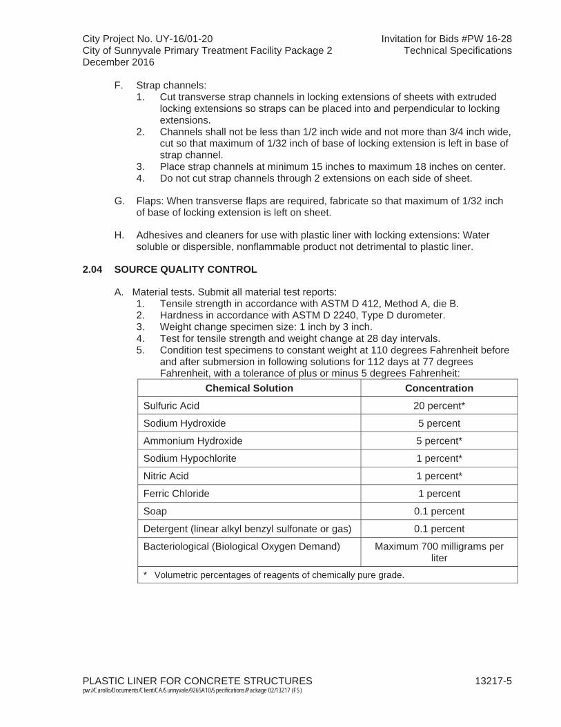
City Project No. UY-16/01-20 Invitation for Bids #PW 16-28City of Sunnyvale Primary Treatment Facility Package 2 Technical SpecificationsDecember 2016
PLASTIC LINER FOR CONCRETE STRUCTURES 13217-5 pw://Carollo/Documents/Client/CA/Sunnyvale/9265A10/Specifications/Package 02/13217 (FS)
F. Strap channels: 1. Cut transverse strap channels in locking extensions of sheets with extruded
locking extensions so straps can be placed into and perpendicular to locking extensions.
2. Channels shall not be less than 1/2 inch wide and not more than 3/4 inch wide, cut so that maximum of 1/32 inch of base of locking extension is left in base of strap channel.
3. Place strap channels at minimum 15 inches to maximum 18 inches on center.4. Do not cut strap channels through 2 extensions on each side of sheet.
G. Flaps: When transverse flaps are required, fabricate so that maximum of 1/32 inch of base of locking extension is left on sheet.
H. Adhesives and cleaners for use with plastic liner with locking extensions: Water soluble or dispersible, nonflammable product not detrimental to plastic liner.
2.04 SOURCE QUALITY CONTROL
A. Material tests. Submit all material test reports: 1. Tensile strength in accordance with ASTM D 412, Method A, die B. 2. Hardness in accordance with ASTM D 2240, Type D durometer.3. Weight change specimen size: 1 inch by 3 inch.4. Test for tensile strength and weight change at 28 day intervals.5. Condition test specimens to constant weight at 110 degrees Fahrenheit before
and after submersion in following solutions for 112 days at 77 degrees Fahrenheit, with a tolerance of plus or minus 5 degrees Fahrenheit:
Chemical Solution ConcentrationSulfuric Acid 20 percent*
Sodium Hydroxide 5 percent
Ammonium Hydroxide 5 percent*
Sodium Hypochlorite 1 percent*
Nitric Acid 1 percent*
Ferric Chloride 1 percent
Soap 0.1 percent
Detergent (linear alkyl benzyl sulfonate or gas) 0.1 percent
Bacteriological (Biological Oxygen Demand) Maximum 700 milligrams per liter
* Volumetric percentages of reagents of chemically pure grade.

City Project No. UY-16/01-20 Invitation for Bids #PW 16-28City of Sunnyvale Primary Treatment Facility Package 2 Technical SpecificationsDecember 2016
PLASTIC LINER FOR CONCRETE STRUCTURES 13217-6 pw://Carollo/Documents/Client/CA/Sunnyvale/9265A10/Specifications/Package 02/13217 (FS)
6. Plastic liner sheets, joint, corner, and welding strips shall have following physical properties when tested at 77 degrees Fahrenheit, with a tolerance of plus or minus 5 degrees Fahrenheit:
Property Initial
After 112 Days Submersion in Previously Specified Chemical
SolutionsTensile Strength 2,200 pounds per square
inch minimum2,100 pounds per square inch
minimum
Elongation at Break 200 percent minimum 200 percent minimum
Shore Durometer, Type D
Within 1 second 50-60; at 10 seconds 35-50
Within 5 with respect with respect to initial test result
Weight Change Within 1.5 percent maximum7. Liner locking extension embedded in concrete shall withstand test pull of at
least 100 pounds per linear inch, applied perpendicularly to concrete surface for 1 minute, without rupture of locking extensions or withdrawal from embedment.
8. Perform tests at temperature between 70 degrees Fahrenheit to 80 degrees Fahrenheit, inclusive.
9. Plastic liner sheets, including locking extensions, and joint, corner, and welding strips shall be free of cracks, cleavages, and defects adversely affecting protective characteristics of material.
B. Tests for holes: 1. Test liner for holes using spark detector.2. Repair sheets having holes and retest liners until no holes are found.
C. Tests of welded joints:1. Examine specimens for cracks or separations.2. Test specimens in tension after flexing.3. Specimen shall withstand minimum load of 132 pounds per linear inch of weld,
or product of 2,000 pounds per square inch times minimum thickness in inches of material adjoining weld, whichever is greater.
4. Thickness shall be taken within 2 inch gauge length.5. Reject liner and liner joints containing tears, cracks, or separations.
PART 3 EXECUTION
3.01 PREPARATION
A. Surface preparation: Use patterns or mark sheet layouts directly on forms where complicated or warped surfaces are involved.

City Project No. UY-16/01-20 Invitation for Bids #PW 16-28City of Sunnyvale Primary Treatment Facility Package 2 Technical SpecificationsDecember 2016
PLASTIC LINER FOR CONCRETE STRUCTURES 13217-7 pw://Carollo/Documents/Client/CA/Sunnyvale/9265A10/Specifications/Package 02/13217 (FS)
3.02 INSTALLATION
A. Positioning liner: 1. Position liner installed in cast-in-place structure so locking extensions are
parallel to axis of structures.2. Closely fit liner sheets to inner forms.3. Cut sheets to fit curved and warped surfaces, using minimum number of
separate pieces.
B. Securing liner in place: 1. Finish nails may be used on wood forms.2. Where form ties or form stabilizing rods pass through liner, make provisions to
maintain liner in close contact with forms during concrete placement.
C. Liner returns: 1. Install liner returns where indicated on the Drawings and wherever surfaces
lined with plastic liner join surfaces which are not lined, such as brick, clay pipe, cast iron pipe, manhole frames, and metal or clay tile gate guides.
2. Fabricate liner returns by joining minimum 3 inch wide strips of liner to main liner with corner strips.
3. Continuously weld corner strips to returns and to main liner and wherever possible, apply from back of lining.
4. Provide locking extensions on returns to lock returns to concrete of plastic lined, cast-in-place structures.
5. Seal liner to adjacent construction.
3.03 CONCRETE OPERATIONS
A. Concrete placement: 1. Carefully vibrate concrete placed against liner to avoid damage to liner and to
produce dense, homogeneous concrete securely anchoring locking extensions into concrete.
2. Use external vibrators in addition to internal vibrators, particularly along lower terminal edge of plastic liner.
B. Removing forms: 1. In removing forms, protect liner from damage.2. Do not use sharp instruments to pry forms from lined surfaces.3. When forms are removed, pull nails that remain in liner without tearing liner,
and clearly mark resulting holes.4. Mark form tie holes before ties are broken off.5. Within limits of unlined invert, remove banding straps used in securing liner to
forms for cast-in-place structures, and fill voids left in invert at edge of liner with cement mortar or other material acceptable to Engineer.
3.04 FIELD JOINTING OF LINER
A. General:1. Liner at joints shall be free of mortar and other foreign materials and shall be
clean and dry before joints are made.
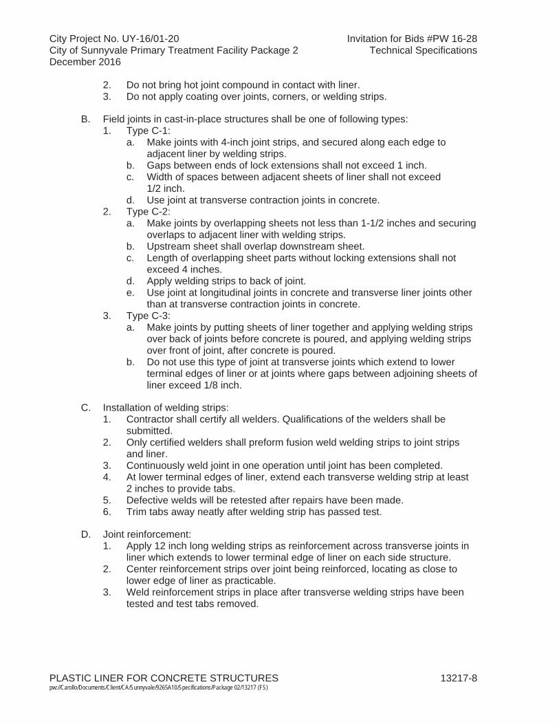
City Project No. UY-16/01-20 Invitation for Bids #PW 16-28City of Sunnyvale Primary Treatment Facility Package 2 Technical SpecificationsDecember 2016
PLASTIC LINER FOR CONCRETE STRUCTURES 13217-8 pw://Carollo/Documents/Client/CA/Sunnyvale/9265A10/Specifications/Package 02/13217 (FS)
2. Do not bring hot joint compound in contact with liner.3. Do not apply coating over joints, corners, or welding strips.
B. Field joints in cast-in-place structures shall be one of following types: 1. Type C-1:
a. Make joints with 4-inch joint strips, and secured along each edge to adjacent liner by welding strips.
b. Gaps between ends of lock extensions shall not exceed 1 inch.c. Width of spaces between adjacent sheets of liner shall not exceed
1/2 inch.d. Use joint at transverse contraction joints in concrete.
2. Type C-2:a. Make joints by overlapping sheets not less than 1-1/2 inches and securing
overlaps to adjacent liner with welding strips.b. Upstream sheet shall overlap downstream sheet.c. Length of overlapping sheet parts without locking extensions shall not
exceed 4 inches.d. Apply welding strips to back of joint.e. Use joint at longitudinal joints in concrete and transverse liner joints other
than at transverse contraction joints in concrete.3. Type C-3:
a. Make joints by putting sheets of liner together and applying welding strips over back of joints before concrete is poured, and applying welding strips over front of joint, after concrete is poured.
b. Do not use this type of joint at transverse joints which extend to lower terminal edges of liner or at joints where gaps between adjoining sheets of liner exceed 1/8 inch.
C. Installation of welding strips: 1. Contractor shall certify all welders. Qualifications of the welders shall be
submitted.2. Only certified welders shall preform fusion weld welding strips to joint strips
and liner.3. Continuously weld joint in one operation until joint has been completed.4. At lower terminal edges of liner, extend each transverse welding strip at least
2 inches to provide tabs.5. Defective welds will be retested after repairs have been made.6. Trim tabs away neatly after welding strip has passed test.
D. Joint reinforcement: 1. Apply 12 inch long welding strips as reinforcement across transverse joints in
liner which extends to lower terminal edge of liner on each side structure.2. Center reinforcement strips over joint being reinforced, locating as close to
lower edge of liner as practicable.3. Weld reinforcement strips in place after transverse welding strips have been
tested and test tabs removed.

City Project No. UY-16/01-20 Invitation for Bids #PW 16-28City of Sunnyvale Primary Treatment Facility Package 2 Technical SpecificationsDecember 2016
PLASTIC LINER FOR CONCRETE STRUCTURES 13217-9 pw://Carollo/Documents/Client/CA/Sunnyvale/9265A10/Specifications/Package 02/13217 (FS)
3.05 FIELD QUALITY CONTROL
A. Contractor shall retain a third-party qualified firm to perform all coating testing and inspections and to perform the following tests. Submit all results of the field testing: 1. Clean surface of liner to permit visual inspection and spark testing.2. Physically test all welds with nondestructive probing method.3. Liner, when installed, may be tested by Engineer, using spark type detector.4. Properly repair and retest areas of liner failing to meet field test.5. Use spark type detector for testing.6. Test each transverse welding strip which extends to lower edge of liner.7. Extend welding strips below liner to form tabs.8. Apply 10 pound pull normal to face of structure by means of spring balance.9. Hold liner adjoining welding strip against concrete during application of force.10. Maintain 10 pound pull when weld failure develops, until no further separation
occurs.11. Retest defective welds after repairs have been made.12. Trim tabs away neatly after welding strip has passed inspection.13. Provide equipment required to test liner in accordance with manufacturer's
instructions.14. Provide personnel qualified to perform testing.15. Perform testing in presence of Construction Manager.
B. Inspections: Liner shall be applied and secured to forms and inspected by Contractor prior to placement of reinforcing steel as specified in Section 03200.
3.06 PROTECTION AND REPAIR
A. Take necessary measures and precautions to prevent damage to liner from equipment and materials used in, or taken through Work.
B. Repair damage to installed liner as follows: 1. Patch nail and tie holes and cuts, tears, and abraded areas.2. Fuse patches made entirely with welding strip to liner over entire patch:
a. Limit use of this method to patches which can be made with single welding strip.
3. Do not use parallel, overlapping, or adjoining welding strips.4. Larger patches may consist of smooth liner over damaged area with edges
covered with welding strips fused to patch and to liner adjoining damaged area.
5. Limit width of single patch of latter type to 4 inches.
END OF SECTION

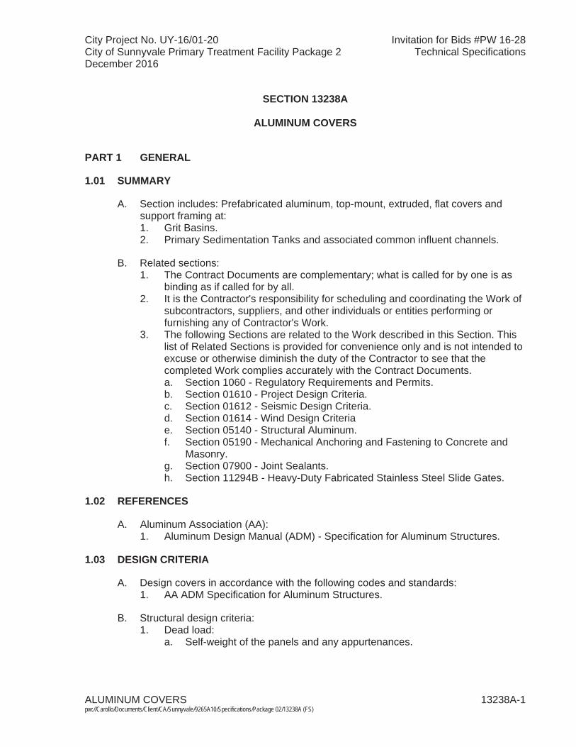
City Project No. UY-16/01-20 Invitation for Bids #PW 16-28City of Sunnyvale Primary Treatment Facility Package 2 Technical SpecificationsDecember 2016
ALUMINUM COVERS 13238A-1 pw://Carollo/Documents/Client/CA/Sunnyvale/9265A10/Specifications/Package 02/13238A (FS)
SECTION 13238A
ALUMINUM COVERS
PART 1 GENERAL
1.01 SUMMARY
A. Section includes: Prefabricated aluminum, top-mount, extruded, flat covers andsupport framing at:1. Grit Basins.2. Primary Sedimentation Tanks and associated common influent channels.
B. Related sections:1. The Contract Documents are complementary; what is called for by one is as
binding as if called for by all.2. It is the Contractor's responsibility for scheduling and coordinating the Work of
subcontractors, suppliers, and other individuals or entities performing or furnishing any of Contractor's Work.
3. The following Sections are related to the Work described in this Section. This list of Related Sections is provided for convenience only and is not intended to excuse or otherwise diminish the duty of the Contractor to see that the completed Work complies accurately with the Contract Documents.a. Section 1060 - Regulatory Requirements and Permits. b. Section 01610 - Project Design Criteria.c. Section 01612 - Seismic Design Criteria. d. Section 01614 - Wind Design Criteriae. Section 05140 - Structural Aluminum.f. Section 05190 - Mechanical Anchoring and Fastening to Concrete and
Masonry.g. Section 07900 - Joint Sealants. h. Section 11294B - Heavy-Duty Fabricated Stainless Steel Slide Gates.
1.02 REFERENCES
A. Aluminum Association (AA): 1. Aluminum Design Manual (ADM) - Specification for Aluminum Structures.
1.03 DESIGN CRITERIA
A. Design covers in accordance with the following codes and standards:1. AA ADM Specification for Aluminum Structures.
B. Structural design criteria:1. Dead load:
a. Self-weight of the panels and any appurtenances.

City Project No. UY-16/01-20 Invitation for Bids #PW 16-28City of Sunnyvale Primary Treatment Facility Package 2 Technical SpecificationsDecember 2016
ALUMINUM COVERS 13238A-2 pw://Carollo/Documents/Client/CA/Sunnyvale/9265A10/Specifications/Package 02/13238A (FS)
2. Live load:a. Uniform live load of 40 pounds per square foot.b. Concentrated live load of 400 pounds distributed over an area measuring
1-foot by 1-foot square area and so placed to create the maximum load effects on the members.
3. Deflection limits:a. Maximum deflection of L/240 for the applied live load. b. Dead load deflection shall not cause visible sagging and/or surface
ponding on the covers.4. Additional service loads:
a. Vacuum under-pressure of 1 inch of water column.5. Seismic load criteria as specified in Section 01612. 6. Wind load criteria as specified in Section 01614. 7. Thermal expansion and contraction:
a. Designed to accommodate effects of temperature changes as specified in the project design criteria in Section 01610.
8. Load combinations for design shall be as specified in the regulatory building code. Refer to Section 01060.
9. Supporting structural components of the covers shall be integrated into the cover, i.e., not exposed above or below the cover.
1.04 SUBMITTALS
A. Shop drawings: Include the following:1. Dimensions, sizes, thicknesses, gauges, materials, and finishes.2. Details of connections, supports, anchorage, penetrations, flashing, and
sealants.3. Attachment and erection procedures.4. Number and location of penetrations.5. Access hatch locations.6. Special details not specifically indicated on the Drawings. 7. Signed and sealed by a qualified Civil or Structural Engineer licensed in the
state of California.
B. Product data: Include technical data and specifications.
C. Calculations: Include for flat cover, signed and sealed by a qualified Civil or Structural Engineer licensed in the state of California.
D. Evidence of manufacturer qualifications: Include personnel experience, physical facilities, management capacity, and minimum 5 reference projects at wastewater treatment facilities that are similar to the Project in scope, size, and application.
E. Certification Letter:1. Signed and sealed by a qualified Civil or Structural Engineer licensed in the
state of California.2. Certify that the aluminum cover design is in full compliance with the plans,
specifications, and regulatory building code.

City Project No. UY-16/01-20 Invitation for Bids #PW 16-28City of Sunnyvale Primary Treatment Facility Package 2 Technical SpecificationsDecember 2016
ALUMINUM COVERS 13238A-3 pw://Carollo/Documents/Client/CA/Sunnyvale/9265A10/Specifications/Package 02/13238A (FS)
F. Operations and Maintenance Manual:1. Include drawings, maintenance instructions, and removal/replacement
instructions for installed covers.
G. Warranty.
1.05 QUALITY ASSURANCE
A. Manufacturer qualifications: Manufacturer of aluminum covers for a minimum of10 years with a minimum of 5 installations under satisfactory operation at wastewater treatment facilities for at least 3 years.
B. Erector qualifications: Skilled and experienced in fabrication and erection of aluminum structures with minimum 5 installations under satisfactory operation.
1.06 WARRANTY
A. The cover system shall be guaranteed 5 years against defective materials and workmanship.
B. Warranty period shall begin on the date of substantial completion.
PART 2 PRODUCTS
2.01 MANUFACTURERS
A. Aluminum covers: One of the following, or equal: 1. CST Covers, Gardena, CA: Extruded Flat Covers (EFC). 2. Hallsten Corporation: Type 2014-Installation Diagram-SurfMoun-Panel.
2.02 MATERIALS
A. Aluminum extrusions: 6061-T6 alloy, 6063-T6 mill-finished.
B. Structural aluminum beams and shapes for support members and stability bracing:As specified in Section 05140.
C. Closure-flashing-to-panel seals: 3/8-inch Hypalon, Santoprene, or Neoprenegaskets.
D. Sealant: Silicone as specified in Section 07900 or Sikaflex 1a.
E. Bitumastic coating: As specified in Section 05140.
F. Threaded fasteners and concrete anchors: Type 316 stainless steel as specified in Section 05190.
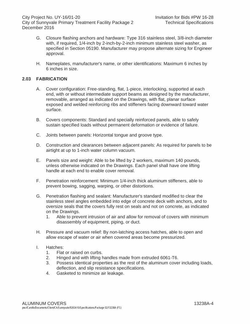
City Project No. UY-16/01-20 Invitation for Bids #PW 16-28City of Sunnyvale Primary Treatment Facility Package 2 Technical SpecificationsDecember 2016
ALUMINUM COVERS 13238A-4 pw://Carollo/Documents/Client/CA/Sunnyvale/9265A10/Specifications/Package 02/13238A (FS)
G. Closure flashing anchors and hardware: Type 316 stainless steel, 3/8-inch diameter with, if required, 1/4-inch by 2-inch-by-2-inch minimum stainless steel washer, as specified in Section 05190. Manufacturer may propose alternate sizing for Engineer approval.
H. Nameplates, manufacturer's name, or other identifications: Maximum 6 inches by 6 inches in size.
2.03 FABRICATION
A. Cover configuration: Free-standing, flat, 1-piece, interlocking, supported at each end, with or without intermediate support beams as designed by the manufacturer,removable, arranged as indicated on the Drawings, with flat, planar surface exposed and welded reinforcing ribs and stiffeners facing downward toward water surface.
B. Covers components: Standard and specially reinforced panels, able to safely sustain specified loads without permanent deformation or evidence of failure.
C. Joints between panels: Horizontal tongue and groove type.
D. Construction and clearances between adjacent panels: As required for panels to be airtight at up to 1-inch water column vacuum.
E. Panels size and weight: Able to be lifted by 2 workers, maximum 140 pounds, unless otherwise indicated on the Drawings. Each panel shall have one lifting handle at each end to enable cover removal.
F. Penetration reinforcement: Minimum 1/4-inch thick aluminum stiffeners, able to prevent bowing, sagging, warping, or other distortions.
G. Penetration flashing and sealant: Manufacturer's standard modified to clear the stainless steel angles embedded into edge of concrete deck with anchors, and to oversize seals that the covers fully rest on seals and not on concrete, as indicated on the Drawings. 1. Able to prevent intrusion of air and allow for removal of covers with minimum
disassembly of equipment, piping, or duct.
H. Pressure and vacuum relief: By non-latching access hatches, able to open and allow escape of water or air when covered areas become pressurized.
I. Hatches:1. Flat or raised on curbs.2. Hinged and with lifting handles made from extruded 6061-T6.3. Possess identical properties as the rest of the aluminum cover including loads,
deflection, and slip resistance specifications.4. Gasketed to minimize air leakage.
City Project No. UY-16/01-20 Invitation for Bids #PW 16-28City of Sunnyvale Primary Treatment Facility Package 2 Technical SpecificationsDecember 2016
ALUMINUM COVERS 13238A-5 pw://Carollo/Documents/Client/CA/Sunnyvale/9265A10/Specifications/Package 02/13238A (FS)
5. Locate as indicated on the Drawings.6. Opening direction as indicated on the Drawings.7. Size indicated on the Drawings is the minimum required.
J. Panel top surface: Integral non-skid, manufactured as part of panels.
PART 3 EXECUTION
3.01 ERECTION
A. Erect covers in accordance with manufacturer's instructions.
B. Plumb and erect flat covers in proper alignment.
C. Install closure flashing, including seal between flashing lip and tops of panels continuously around entire perimeter of cover assembly.
D. Secure closure flashing to existing concrete walls and slabs with drilled and epoxied anchors as specified in Section 05190.
E. Secure closure flashing to new concrete using cast-in-place anchor bolts as specified in Section 05190 or epoxy anchors.
F. Place anchors and fasteners at each corner of each panel and at a spacing center along concrete walls and metal framing supports per approved calculations.
G. Anchor embedment: Minimum 4 inches or per approved calculations.
H. Isolate panel bearing ends, closure flashing, and other aluminum from concrete and dissimilar metals per Section 05140.
END OF SECTION


City Project No. UY-16/01-20 Invitation for Bids #PW 16-28City of Sunnyvale Primary Treatment Facility Package 2 Technical SpecificationsDecember 2016
FIBERGLASS REINFORCED PLASTIC TANKS 13420-1 pw://Carollo/Documents/Client/CA/Sunnyvale/9265A10/Specifications/Package 02/13420 (FS)
SECTION 13420
FIBERGLASS REINFORCED PLASTIC TANKS
PART 1 GENERAL
1.01 SUMMARY
A. Section includes:1. Two vertical fiberglass reinforced plastic (FRP) insulated ferric chloride storage
tanks for outdoor chemical storage.
B. Related sections:1. The Contract Documents are complementary; what is called for by one is as
binding as if called for by all.2. It is the Contractor's responsibility for scheduling and coordinating the Work of
subcontractors, suppliers, and other individuals or entities performing or furnishing any of Contractor's Work.
3. The following Sections are related to the Work described in this Section. This list of Related Sections is provided for convenience only and is not intended to excuse or otherwise diminish the duty of the Contractor to see that the completed Work complies accurately with the Contract Documents:a. Section 01010 - Summary of Work. b. Section 01340 - Shop Drawings, Product Data and Samples. c. Section 01610 - Project Design Criteria.d. Section 01756 - Commissioning and Process Start-Up.e. Section 01730 - Operation and Maintenance Data.f. Section 05190 - Mechanical Anchoring and Fastening to Concrete and
Masonry.g. Section 06608 - Fiberglass Reinforced Plastic. h. Section 06611 - Fiberglass Reinforced Plastic Fabrications.
1.02 REFERENCES
A. American National Standards Institute (ANSI):1. B16.5, Pipe Flanges and Flanged Fittings.
B. ASTM International (ASTM):1. C 582, Standard Specification for Reinforced Plastic Laminates for
Self-Supporting Structures for Use in a Chemical Environment.2. D 638, Standard Test Method for Tensile Properties of Plastics.3. D 2563, Standard Practice for Classifying Visual Defects in Glass – Reinforced
Plastic Laminate Parts.4. D 2584, Standard Test Method for Ignition Loss of Cured Reinforced Plastic. 5. D 3299, Specification for Filament-Wound-Glass Fiber-Reinforced Thermoset
Resin Chemical-Resistant Tanks.
City Project No. UY-16/01-20 Invitation for Bids #PW 16-28City of Sunnyvale Primary Treatment Facility Package 2 Technical SpecificationsDecember 2016
FIBERGLASS REINFORCED PLASTIC TANKS 13420-2 pw://Carollo/Documents/Client/CA/Sunnyvale/9265A10/Specifications/Package 02/13420 (FS)
C. D4097, Specification for Contact Molded Glass-Fiber-Reinforced Thermoset Resin Chemical-Resistant Tanks. NACE International (NACE): 1. NACE-4, Brush-Off Blast Cleaning.
D. Society for Protective Coatings (SSPC):1. SSPC-SP1, Solvent Cleaning.2. SSPC-SP7, Brush-Off Blast Cleaning of Non-Ferrous Metals.
1.03 QUALITY ASSURANCE
A. As specified in Section 06608 and 06611.
B. Manufacture's Certificate of Installation and Functionality Compliance as specified in Section 01756.
C. References: Provide references for a minimum of 10 installations to show successful performance of the proposed tanks in continuous service for a minimum of 5 years under similar operating conditions. Reference information shall include location, service, contact person and contact phone number.
D. Provide tanks specified in this section from same manufacturer.
1.04 SYSTEM DESCRIPTION
A. Ferric chloride storage tanks with components:1. Tank, nozzles, ladder, guardrail, manway access, vents, seismic restraints,
supports, anchor bolts, and other items as required for a complete and operational system.
2. Service: 40 percent concentration ferric chloride.3. UV-treated for outdoor installation
1.05 SUBMITTALS
A. Shop drawings shall include detailed design calculations stamped by a registered engineer, bill of material listing all components, resins, catalysts, promoters, ultraviolet light absorbers, agents, reinforcing material, etc., with manufacturer'sname, trade, and identification marks. The laminate sequence used for all tanks must either be attached to or included on drawings used by the fabricator's shop personnel.
B. Shop drawings:1. See Specification Section 01340 for requirements for the mechanics and
administration of the submittal process.2. Product technical data including:
a. Name of manufacturer.b. Dimension including anchor bolt layouts.c. Nozzle schedule including size, thickness or schedule, pressure rating,
elevation, and orientation.d. Details of all clips and lugs for ladders, stairs, platforms, hold down lugs,
pipe brackets, pipe supports, and anchor bolts, used as integral parts of

City Project No. UY-16/01-20 Invitation for Bids #PW 16-28City of Sunnyvale Primary Treatment Facility Package 2 Technical SpecificationsDecember 2016
FIBERGLASS REINFORCED PLASTIC TANKS 13420-3 pw://Carollo/Documents/Client/CA/Sunnyvale/9265A10/Specifications/Package 02/13420 (FS)
the tank shall be accompanied with calculations verifying stability of the tanks. Calculations showing compliance with OSHA and building code requirements shall be stamped and signed by a state of Californiaregistered civil or structural engineer.
e. Details of structural support members. The spacing on all tank supported pipe supports shall be a maximum 5 feet on centers.
f. Equipment capacity (gallons).g. Maximum design specific gravity.h. Maximum design temperature.i. Equipment weights, empty and filled with the liquid to be stored in the
tank.j. Laminate sequence of construction and all materials of construction listed.k. Resin, type and hardness and catalysts, promoters, ultraviolet light
absorber, agent to be used.l. Curing compounds and cure process.m. Liquid level gage including guard details where applicable.n. References for filament wound.o. Specification and recommended torques for all supplied bolting, gaskets,
and accessory items.p. Structural and seismic calculations for tank and anchoring system. All
calculations along with design details shall be made and signed by a Civil or Structural Engineer currently registered in the State of California.
q. Design criteria for the following physical laminate properties for fabricated round tanks:1) Tensile strength of the laminate.2) Flexural strength of the laminate.3) Tangent Modulus of the laminate.4) Minimum physical properties for the test enumerated in ASTM C 582.5) Strain Modulus per ASTM C 582.
r. Identification of products to be used for coating the tanks.s. Acknowledgement that products submitted meet requirements of
standards referenced.t. Manufacturer's installation instructions.
C. Equipment anchorage calculations as specified in Section 15050.
D. Factory test reports:1. Each tank shall be given a hydrostatic test by the manufacturer before
shipment. Conduct tests on actual equipment to be furnished to the job site.2. Each tank shall be inspected for defects in accordance with the requirements
of ASTM D 2563.3. Surface Cure: Tanks shall be tested for the degree of surface cure using
Barcol hardness and acetone sensitivity methods as indicated in the referenced ASTM standards. Submit certified test reports.
4. Laminate Quality: Tanks shall be visually inspected for laminate quality and workmanship as indicated in the reference ASTM standards.
E. Operation and Maintenance Manuals as specified in Section 01730.
City Project No. UY-16/01-20 Invitation for Bids #PW 16-28City of Sunnyvale Primary Treatment Facility Package 2 Technical SpecificationsDecember 2016
FIBERGLASS REINFORCED PLASTIC TANKS 13420-4 pw://Carollo/Documents/Client/CA/Sunnyvale/9265A10/Specifications/Package 02/13420 (FS)
1.06 PROJECT CONDITIONS
A. Environmental requirements: As specified in Section 01610.
1.07 SEQUENCING AND SCHEDULING
A. Coordinate work with restrictions as specified in Section 01010.
B. Coordinate work with Commissioning and Start-up as specified in Section 01756.
1.08 WARRANTY
A. Provide a Manufacturer's warranty meeting the requirement of Section 01740.
PART 2 PRODUCTS
2.01 ACCEPTABLE MANUFACTURERS
A. One of the following or equal: 1. Fiberglass reinforced plastic tanks:
a. Belco. b. Justin Tank, LLC. c. Tankinetics.
2.02 SERVICE CONDITIONS
A. Normal temperature: 40 degrees Fahrenheit to 150 degrees Fahrenheit, outdoor installation.
B. Normal internal loads: Hydrostatics.
C. Chemical centration and properties:1. Ferric Chloride:
a. Liquid: Approx. 40 percent concentration. b. Specific gravity: 1.4 at 30 degrees Celsius and 40 percent concentration
by weight. c. pH <2. d. Pressure: Atmospheric. e. NFPA Rating: health – 2, flammability – 0, reactivity - 0.
2.03 MATERIALS
A. General:1. Resins:
a. Resin to be recommended by a resin manufacturer for the stated service conditions.
b. A letter of suitability is to be provided by the resin manufacturer.

City Project No. UY-16/01-20 Invitation for Bids #PW 16-28City of Sunnyvale Primary Treatment Facility Package 2 Technical SpecificationsDecember 2016
FIBERGLASS REINFORCED PLASTIC TANKS 13420-5 pw://Carollo/Documents/Client/CA/Sunnyvale/9265A10/Specifications/Package 02/13420 (FS)
c. The same resin shall be used throughout the structure.d. Resin to be promoted and cured using materials specifically
recommended by the resin manufacturer.2. Reinforcement:
a. Surfacing veil: Type C glass with silane finish and styrene-soluble barrier at 20 mils thick and interior Nexus.
b. Chopped strand mat: Type E glass with silane finish and styrene-soluble binder.
c. Continuous roving: Type E glass with chrome finish or silane finish.d. Woven roving: Type E glass with silane finish.e. Woven cloth: Type E glass with silane finish.
3. Exposed metal: Stainless steel, ANSI Type 316.4. Lifting lugs: Stainless steel, ANSI Type 304.
2.04 ACCESSORIES
A. Flanges nozzles:1. Conically gusseted to tank, withstand 1,500 pounds bending,
2,000 foot/pounds torque.2. Flange diameter and drilling per ANSI B16.5, 150 pounds. 3. At least 4 inches from outside face.4. Same material as tank.5. Location and sizes as shown on Drawings.
B. Vents: Screened mushroom or gooseneck type.
C. Handling lugs.
D. FRP Ladder – supported at every 3 feet.
E. FRP guardrail around roof.
F. Manway:1. One 24-inch diameter access manway in top of each tank.2. One 24-inch diameter access manway on side wall of each tank.3. Flange diameter and drilling per ANSI B16.5, 150 pounds. 4. 40-50 durometer 1/8-inch thick full-faced gaskets.
G. Insulation:1. Polyurethane:
a. 1-inch minimum thickness.b. Minimum R-value: 6.8.c. Protect with exterior fiberglass protective laminate, minimum 1/8-inch
thickness.d. Minimum one external horizontal expansion joint to allow thermal
expansion.
City Project No. UY-16/01-20 Invitation for Bids #PW 16-28City of Sunnyvale Primary Treatment Facility Package 2 Technical SpecificationsDecember 2016
FIBERGLASS REINFORCED PLASTIC TANKS 13420-6 pw://Carollo/Documents/Client/CA/Sunnyvale/9265A10/Specifications/Package 02/13420 (FS)
H. Tank penetrations:
PurposePort Size Quantity Elevation
Fill 2-in 1 On Cover
Pump suction 1-in 1 On Wall, See Process Syphon Nozzle – Typical Detail M002
Drain 2-in 1 On Wall, See Bottom Drain Nozzle - Typical Detail M002
Overflow 3-in 1 On Wall, See Overflow Nozzle – Typical Detail M002
Vent 4-in 1 On Cover
Manway 24-in 2 1. On Wall, Centerline -3'-0" from Tank Bottom
2. On Cover
Magnetic Float Level Gauge 2-in 2 1. On Wall, Centerline - 6-in from Tank Bottom
2. On Wall, Centerline – 6-infrom top of straight height
Ultrasonic Level Indicator and Transmitter
6-in 1 On Cover
1. See Drawing 246M01 for tank penetration orientation and Typical Detail M002.
2.05 FABRICATION
A. Size and dimensions:1. Ferric Chloride Tanks:
a. Number of tanks: 2.b. Nominal capacity: 5,000 gallons. c. Approximate diameter: 8.5 feet. d. Approximate height: 12 feet.
B. Shape: Cylindrical with flat bottom and closed domed top.
C. Design loads:1. Seismic requirements: See Section 01612. 2. Anchorage requirements: See Section 15050. 3. Concentrated top load: 30 psf plus dead load.
D. Design: Per ASTM D 3299, PS-15, and as specified herein, the more stringent requirement to govern.
E. Tanks:1. Filament-wound or contact molded construction.2. Design safety factor and minimum wall thickness per governing standards.
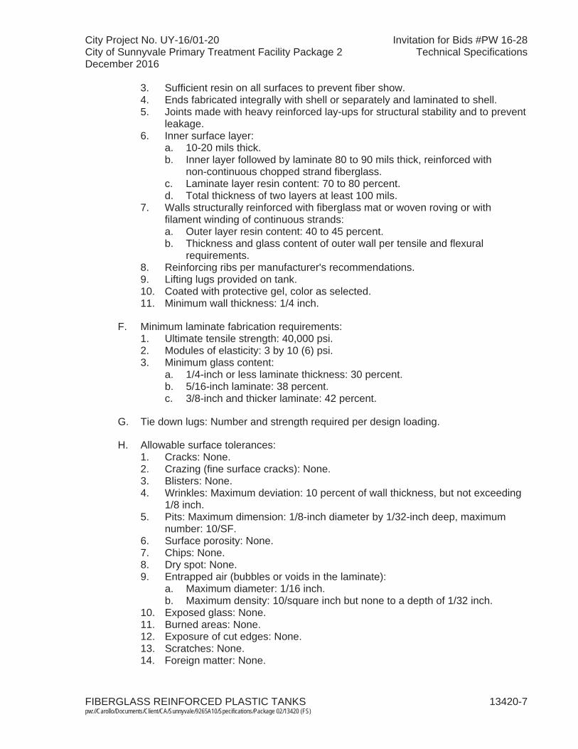
City Project No. UY-16/01-20 Invitation for Bids #PW 16-28City of Sunnyvale Primary Treatment Facility Package 2 Technical SpecificationsDecember 2016
FIBERGLASS REINFORCED PLASTIC TANKS 13420-7 pw://Carollo/Documents/Client/CA/Sunnyvale/9265A10/Specifications/Package 02/13420 (FS)
3. Sufficient resin on all surfaces to prevent fiber show.4. Ends fabricated integrally with shell or separately and laminated to shell.5. Joints made with heavy reinforced lay-ups for structural stability and to prevent
leakage.6. Inner surface layer:
a. 10-20 mils thick.b. Inner layer followed by laminate 80 to 90 mils thick, reinforced with
non-continuous chopped strand fiberglass.c. Laminate layer resin content: 70 to 80 percent.d. Total thickness of two layers at least 100 mils.
7. Walls structurally reinforced with fiberglass mat or woven roving or with filament winding of continuous strands:a. Outer layer resin content: 40 to 45 percent.b. Thickness and glass content of outer wall per tensile and flexural
requirements.8. Reinforcing ribs per manufacturer's recommendations.9. Lifting lugs provided on tank.10. Coated with protective gel, color as selected.11. Minimum wall thickness: 1/4 inch.
F. Minimum laminate fabrication requirements:1. Ultimate tensile strength: 40,000 psi.2. Modules of elasticity: 3 by 10 (6) psi.3. Minimum glass content:
a. 1/4-inch or less laminate thickness: 30 percent.b. 5/16-inch laminate: 38 percent.c. 3/8-inch and thicker laminate: 42 percent.
G. Tie down lugs: Number and strength required per design loading.
H. Allowable surface tolerances:1. Cracks: None.2. Crazing (fine surface cracks): None.3. Blisters: None.4. Wrinkles: Maximum deviation: 10 percent of wall thickness, but not exceeding
1/8 inch. 5. Pits: Maximum dimension: 1/8-inch diameter by 1/32-inch deep, maximum
number: 10/SF.6. Surface porosity: None.7. Chips: None.8. Dry spot: None.9. Entrapped air (bubbles or voids in the laminate):
a. Maximum diameter: 1/16 inch. b. Maximum density: 10/square inch but none to a depth of 1/32 inch.
10. Exposed glass: None.11. Burned areas: None.12. Exposure of cut edges: None.13. Scratches: None.14. Foreign matter: None.
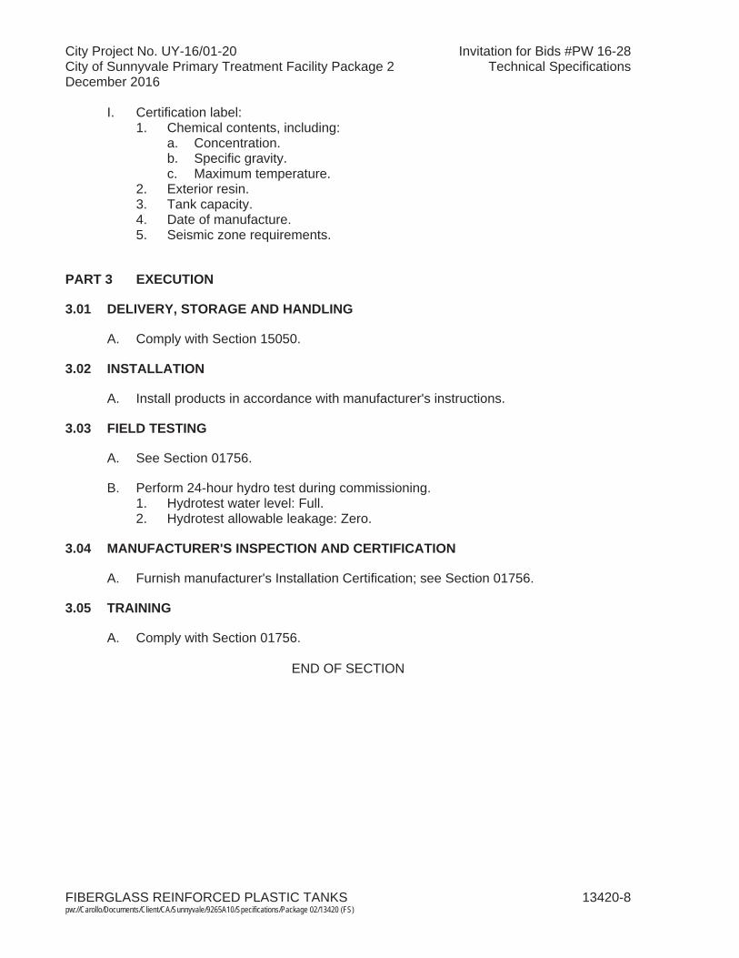
City Project No. UY-16/01-20 Invitation for Bids #PW 16-28City of Sunnyvale Primary Treatment Facility Package 2 Technical SpecificationsDecember 2016
FIBERGLASS REINFORCED PLASTIC TANKS 13420-8 pw://Carollo/Documents/Client/CA/Sunnyvale/9265A10/Specifications/Package 02/13420 (FS)
I. Certification label:1. Chemical contents, including:
a. Concentration.b. Specific gravity.c. Maximum temperature.
2. Exterior resin.3. Tank capacity.4. Date of manufacture.5. Seismic zone requirements.
PART 3 EXECUTION
3.01 DELIVERY, STORAGE AND HANDLING
A. Comply with Section 15050.
3.02 INSTALLATION
A. Install products in accordance with manufacturer's instructions.
3.03 FIELD TESTING
A. See Section 01756.
B. Perform 24-hour hydro test during commissioning. 1. Hydrotest water level: Full. 2. Hydrotest allowable leakage: Zero.
3.04 MANUFACTURER'S INSPECTION AND CERTIFICATION
A. Furnish manufacturer's Installation Certification; see Section 01756.
3.05 TRAINING
A. Comply with Section 01756.
END OF SECTION
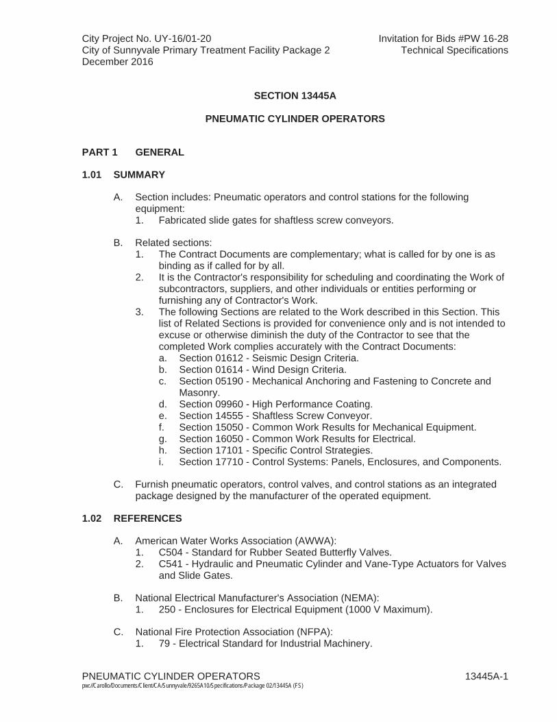
City Project No. UY-16/01-20 Invitation for Bids #PW 16-28City of Sunnyvale Primary Treatment Facility Package 2 Technical SpecificationsDecember 2016
PNEUMATIC CYLINDER OPERATORS 13445A-1 pw://Carollo/Documents/Client/CA/Sunnyvale/9265A10/Specifications/Package 02/13445A (FS)
SECTION 13445A
PNEUMATIC CYLINDER OPERATORS
PART 1 GENERAL
1.01 SUMMARY
A. Section includes: Pneumatic operators and control stations for the following equipment:1. Fabricated slide gates for shaftless screw conveyors.
B. Related sections: 1. The Contract Documents are complementary; what is called for by one is as
binding as if called for by all.2. It is the Contractor's responsibility for scheduling and coordinating the Work of
subcontractors, suppliers, and other individuals or entities performing or furnishing any of Contractor's Work.
3. The following Sections are related to the Work described in this Section. This list of Related Sections is provided for convenience only and is not intended to excuse or otherwise diminish the duty of the Contractor to see that the completed Work complies accurately with the Contract Documents:a. Section 01612 - Seismic Design Criteria.b. Section 01614 - Wind Design Criteria.c. Section 05190 - Mechanical Anchoring and Fastening to Concrete and
Masonry. d. Section 09960 - High Performance Coating. e. Section 14555 - Shaftless Screw Conveyor. f. Section 15050 - Common Work Results for Mechanical Equipment. g. Section 16050 - Common Work Results for Electrical.h. Section 17101 - Specific Control Strategies.i. Section 17710 - Control Systems: Panels, Enclosures, and Components.
C. Furnish pneumatic operators, control valves, and control stations as an integrated package designed by the manufacturer of the operated equipment.
1.02 REFERENCES
A. American Water Works Association (AWWA):1. C504 - Standard for Rubber Seated Butterfly Valves.2. C541 - Hydraulic and Pneumatic Cylinder and Vane-Type Actuators for Valves
and Slide Gates.
B. National Electrical Manufacturer's Association (NEMA): 1. 250 - Enclosures for Electrical Equipment (1000 V Maximum).
C. National Fire Protection Association (NFPA): 1. 79 - Electrical Standard for Industrial Machinery.

City Project No. UY-16/01-20 Invitation for Bids #PW 16-28City of Sunnyvale Primary Treatment Facility Package 2 Technical SpecificationsDecember 2016
PNEUMATIC CYLINDER OPERATORS 13445A-2 pw://Carollo/Documents/Client/CA/Sunnyvale/9265A10/Specifications/Package 02/13445A (FS)
1.03 DEFINITIONS
A. NEMA: 1. Type 4X enclosure in accordance with NEMA 250.2. Type 7 enclosure in accordance with NEMA 250.3. Type 12 enclosure in accordance with NEMA 250.
1.04 SYSTEM DESCRIPTION
A. Design requirements: 1. Pneumatic cylinder operators:
a. In accordance with AWWA C541. b. Valve operator cylinder sizing and system design in accordance with
AWWA C504 for all types of valves.c. Gate operator cylinder sizing and design:
1) Size based on maximum opening or closing force required.2) Safety factors and other design criteria in accordance with
AWWA C504.d. Minimum operating pressure at control valve for cylinder:
1) 60 pounds per square inch gauge.2) Cylinder sizing to account for losses, including valve losses and line
losses from control valve to cylinder.e. Cylinder pressure rating:
1) Pneumatic: 120 pounds per square inch gauge.2. Provide internal stops as required to protect bearings and rod in cylinders with
long actuation length.3. Electrical area classification:
a. All devices and components mounted on the conveyor or conveyor assembly shall be suitable for Class 1, Division 1, Group D hazardous locations, including components on the pneumatic actuators for the slidegates.
B. Performance requirements: 1. Open or close gates at a rate of 30 inches per minute.2. Open or close valves in 15 seconds.
1.05 SUBMITTALS
A. Shop drawings: 1. Include connection details with the submittals.2. System layout drawings.3. Process schematics.
B. Product data.
C. Design data: 1. Sizing calculations for cylinder and rod based on force and break-away
force/sealing force requirements.2. Column head load calculations on blade. 3. System pressure loss calculations.

City Project No. UY-16/01-20 Invitation for Bids #PW 16-28City of Sunnyvale Primary Treatment Facility Package 2 Technical SpecificationsDecember 2016
PNEUMATIC CYLINDER OPERATORS 13445A-3 pw://Carollo/Documents/Client/CA/Sunnyvale/9265A10/Specifications/Package 02/13445A (FS)
4. Calculations to substantiate in accordance with AWWA C504. 5. Other calculations necessary to substantiate conformance with this
specification.
D. Test reports: 1. Proof of design test in accordance with AWWA C541. 2. Performance test in accordance with AWWA C541.
E. Certificates:1. Certification of compliance with proof of design and performance test in
accordance with AWWA C541. 2. Affidavit of compliance in accordance with AWWA C541.
F. Operation and maintenance data.
1.06 QUALITY ASSURANCE
A. Unit responsibility: 1. The pneumatic cylinders shall be supplied by the manufacturer of the
equipment actuated by the cylinder.
1.07 SPARE PARTS
A. Provide the following spare parts: 1. 1 complete set of seals, gaskets, and expendable hardware required for
installation of each spare valve or valve assembly.
B. Package spare parts as specified in Section 15050.
PART 2 PRODUCTS
2.01 MANUFACTURERS
A. Pneumatic cylinder operators: One of the following or equal:1. TRD Manufacturing, Inc./Bimba.2. Parker Hannifin.
2.02 MATERIALS
A. Pneumatic: 1. In accordance with AWWA C541. 2. Non-metallic materials shall be limited to seals only:
a. Non-metallic cylinders are not acceptable.
2.03 EQUIPMENT
A. Cylinder construction: 1. Cylinders: Heavy duty, double acting type with cushions at both ends.
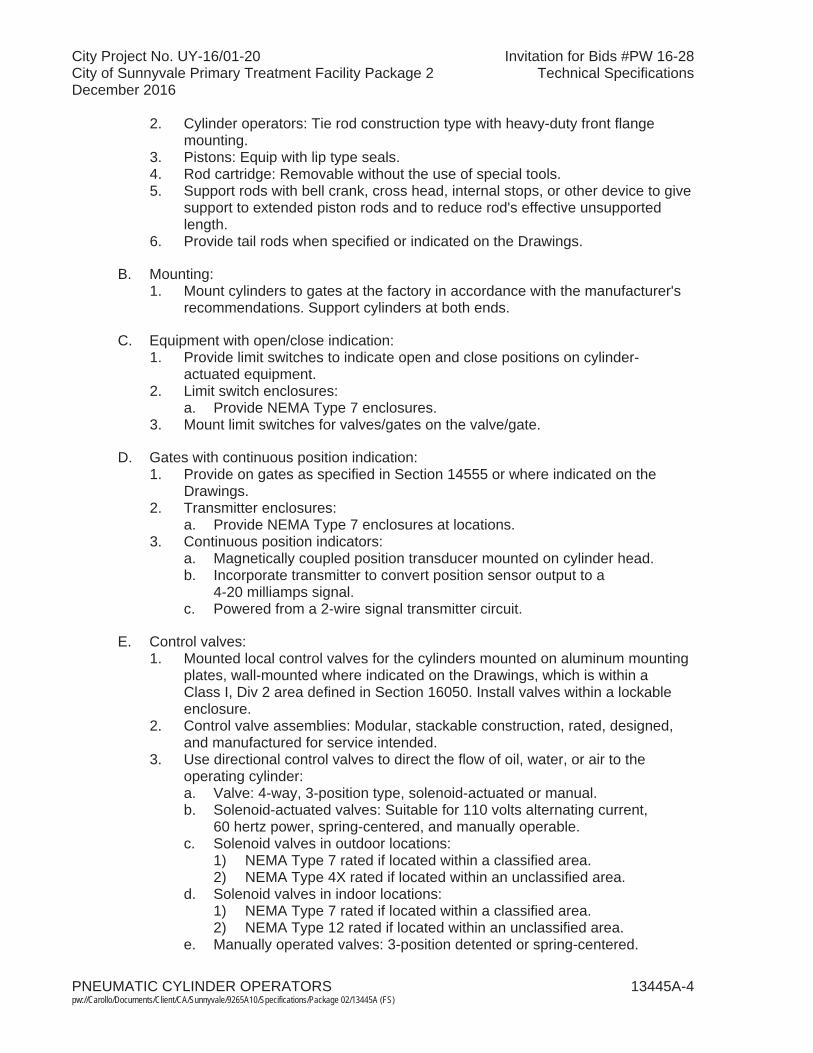
City Project No. UY-16/01-20 Invitation for Bids #PW 16-28City of Sunnyvale Primary Treatment Facility Package 2 Technical SpecificationsDecember 2016
PNEUMATIC CYLINDER OPERATORS 13445A-4 pw://Carollo/Documents/Client/CA/Sunnyvale/9265A10/Specifications/Package 02/13445A (FS)
2. Cylinder operators: Tie rod construction type with heavy-duty front flange mounting.
3. Pistons: Equip with lip type seals.4. Rod cartridge: Removable without the use of special tools.5. Support rods with bell crank, cross head, internal stops, or other device to give
support to extended piston rods and to reduce rod's effective unsupported length.
6. Provide tail rods when specified or indicated on the Drawings.
B. Mounting:1. Mount cylinders to gates at the factory in accordance with the manufacturer's
recommendations. Support cylinders at both ends.
C. Equipment with open/close indication:1. Provide limit switches to indicate open and close positions on cylinder-
actuated equipment.2. Limit switch enclosures:
a. Provide NEMA Type 7 enclosures.3. Mount limit switches for valves/gates on the valve/gate.
D. Gates with continuous position indication: 1. Provide on gates as specified in Section 14555 or where indicated on the
Drawings. 2. Transmitter enclosures:
a. Provide NEMA Type 7 enclosures at locations. 3. Continuous position indicators:
a. Magnetically coupled position transducer mounted on cylinder head.b. Incorporate transmitter to convert position sensor output to a
4-20 milliamps signal.c. Powered from a 2-wire signal transmitter circuit.
E. Control valves: 1. Mounted local control valves for the cylinders mounted on aluminum mounting
plates, wall-mounted where indicated on the Drawings, which is within aClass I, Div 2 area defined in Section 16050. Install valves within a lockable enclosure.
2. Control valve assemblies: Modular, stackable construction, rated, designed, and manufactured for service intended.
3. Use directional control valves to direct the flow of oil, water, or air to the operating cylinder:a. Valve: 4-way, 3-position type, solenoid-actuated or manual.b. Solenoid-actuated valves: Suitable for 110 volts alternating current,
60 hertz power, spring-centered, and manually operable.c. Solenoid valves in outdoor locations:
1) NEMA Type 7 rated if located within a classified area.2) NEMA Type 4X rated if located within an unclassified area.
d. Solenoid valves in indoor locations:1) NEMA Type 7 rated if located within a classified area. 2) NEMA Type 12 rated if located within an unclassified area.
e. Manually operated valves: 3-position detented or spring-centered.

City Project No. UY-16/01-20 Invitation for Bids #PW 16-28City of Sunnyvale Primary Treatment Facility Package 2 Technical SpecificationsDecember 2016
PNEUMATIC CYLINDER OPERATORS 13445A-5 pw://Carollo/Documents/Client/CA/Sunnyvale/9265A10/Specifications/Package 02/13445A (FS)
4. Provide pilot operated check valves to maintain intermediate positioning of the cylinder.
5. Provide pressure regulating valves to permit adjustment of opening and closing thrust of the cylinder.
6. Provide speed control valves with ball check bypass to regulate operating speed of the cylinder.
7. Install isolation ball valves on the oil, water, and air supply and return sides of each control valve assembly, with a union-type or flanged connection between the isolation valve and the control valve assembly.
8. Other valves and accessories: Provided as required to meet the necessary performance requirements.
F. Cylinder connections: Flexible connection with isolation ball valve.
G. Local control stations: 1. Meet requirements of this Section, as specified in Section 17101,
Section 17710, and as indicated on the Drawings. 2. Non-modulating equipment: Incorporate:
a. "LOCAL-STOP-REMOTE" selector switch, with dry contact for "Remote"selection indication.
b. "OPEN- CLOSE" selector switch controls as indicated on the Drawings. c. "OPEN" and "CLOSED" status lights.
3. Modulating equipment: Incorporate:a. Continuous position indicating gauge.
4. Enclosures for local control station enclosures in outdoor locations: Rated NEMA Type 7.
5. Enclosure for local control station enclosures in indoor locations: Rated NEMA Type 12, except that where explosion-proof construction is indicated on the Drawings or required, provide NEMA Type 7 enclosures.
H. Fittings:1. Pneumatic systems: Stainless steel, bronze, or copper.2. Do not connect galvanized pipe fittings to bronze or copper.
I. Coatings:1. Prime coat for exposed metal surfaces including operator, support, and
position indicating devices: As specified in Section 09960.
PART 3 EXECUTION
3.01 INSTALLATION
A. Mount and adjust cylinders on valves at the factory.
B. Field mounted cylinders: Installed as directed by the manufacturer of the actuated equipment.
C. Coordinate installation and startup of the pneumatic system and components.

City Project No. UY-16/01-20 Invitation for Bids #PW 16-28City of Sunnyvale Primary Treatment Facility Package 2 Technical SpecificationsDecember 2016
PNEUMATIC CYLINDER OPERATORS 13445A-6 pw://Carollo/Documents/Client/CA/Sunnyvale/9265A10/Specifications/Package 02/13445A (FS)
3.02 FIELD QUALITY CONTROL
A. Functional testing as specified in Section 15050.
3.03 CYLINDER OPERATOR SCHEDULE
A. Abbreviations relating to valve or gate type:1. BFV = Butterfly Valve.2. RBFV = Rectangular Butterfly Valve.3. RKG = Rectangular Knife Gate.4. BV = Ball Valve.5. DV = Diaphragm Valve.6. PV = Plug Valve.7. SLG = Sluice Gate.8. SG = Slide Gate.
B. Abbreviations relating to operator function:1. O/C = Open and Close Service.2. MOD = Modulating Service.3. FIP = Fail in Last Position.4. FC = Fail Closed.5. FO = Fail Open.
C. Schedule:
Valve Tag
Valve or
Gate Type
Service Fluid
Operator Type
Operator Function
Area Classification
Instrument Air
System Pressure
(psig)
Operating Air
Pressure at Control
Valve(psig)
GAT-212.011 GAT-212.012
RKG Screenings Double Acting
O/C, FIP Class I, Division I
80-120 60
END OF SECTION
City Project No. UY-16/01-20 Invitation for Bids #PW 16-28City of Sunnyvale Primary Treatment Facility Package 2 Technical SpecificationsDecember 2016
MANUAL ACTUATORS 13446-1 pw://Carollo/Documents/Client/CA/Sunnyvale/9265A10/Specifications/Package 02/13446 (FS)
SECTION 13446
MANUAL ACTUATORS
PART 1 GENERAL
1.01 SUMMARY
A. Section includes:1. Valve and gate actuators.2. Handwheel actuators.3. Key operated valves.4. Bench stands.5. Floor stands.6. Accessory equipment and floor boxes.
B. Related sections: 1. The Contract Documents are complementary; what is called for by one is as
binding as if called for by all.2. It is the Contractor's responsibility for scheduling and coordinating the Work of
subcontractors, suppliers, and other individuals or entities performing or furnishing any of Contractor's Work.
3. The following Sections are related to the Work described in this Section. This list of Related Sections is provided for convenience only and is not intended to excuse or otherwise diminish the duty of the Contractor to see that the completed Work complies accurately with the Contract Documents:a. Section 09960 - High-Performance Coatings.b. Section 11294B - Heavy-Duty Fabricated Stainless Steel Gates.
1.02 REFERENCES
A. Aluminum Association (AA): 1. DAF-45 - Designation System for Aluminum Finishes.
B. American Water Works Association (AWWA).
1.03 SUBMITTALS
A. Shop drawings: Include shop drawings and product data with associated gate or valve as an integrated unit.
1.04 QUALITY ASSURANCE
A. Provide valve actuators integral with valve or gate, except for valve actuators utilizing T-wrenches or keys, and portable actuators intended to operate more than 1 valve.

City Project No. UY-16/01-20 Invitation for Bids #PW 16-28City of Sunnyvale Primary Treatment Facility Package 2 Technical SpecificationsDecember 2016
MANUAL ACTUATORS 13446-2 pw://Carollo/Documents/Client/CA/Sunnyvale/9265A10/Specifications/Package 02/13446 (FS)
B. Provide similar actuators by 1 manufacturer.
C. Provide gates and hand operating lifts by 1 manufacturer.
1.05 MAINTENANCE
A. Extra materials:1. Key operated valve keys or wrenches: Furnish a minimum 4 keys with 4-foot
shafts and 3-foot pipe handles or wrenches with 4-foot shafts and 3-foothandles for operating key operated valves.
PART 2 PRODUCTS
2.01 VALVE AND GATE ACTUATORS
A. Stem covers:1. Valve actuators: Aluminum pipe; threaded cap on top; bolted aluminum flange
on bottom; 1- by 12-inch slots cut at 18 inches on center in front and back of pipe; capable of covering threaded portion of greased stems that project above actuators when gates or valves are opened or closed.
2. Gate actuators: Clear plastic stem covers with mylar indicating strips as specified in Section 11294B.
B. Stem cover flanges, pipes and caps:1. After fabrication, etch and anodize to produce the following chemical finishes
in accordance with AA publication DAF-45:a. A 41 - Clear Anodic Coating.b. C 22 - Medium Matte Finish.
C. Gate stem covers: Concentric with stem.
D. Position indicators:1. Tail rods on hydraulic cylinders, or dial indicators with clear full-open and
closed position indicators, calibrated in number of turns or percentage of opening. Indicating strips are also acceptable in conjunction with clear plastic stem covers.
E. Manual or power actuator size:1. Sized to deliver maximum force required under most severe specified
operating condition, including static and dynamic forces, seat and wedge friction, and seating and unseating forces with safety factor of 5, unless otherwise specified.
F. Actuator size: Capable of supporting weight of suspended shafting unless carried by bottom thrust bearings; shaft guides with wall mounting brackets.
G. Provisions for alternate operation: Where specified or indicated on the Drawings,position and equip crank or handwheel operated geared valve actuators or lifts for alternate operation with tripod mounted portable gate actuators.
City Project No. UY-16/01-20 Invitation for Bids #PW 16-28City of Sunnyvale Primary Treatment Facility Package 2 Technical SpecificationsDecember 2016
MANUAL ACTUATORS 13446-3 pw://Carollo/Documents/Client/CA/Sunnyvale/9265A10/Specifications/Package 02/13446 (FS)
H. Operation: Counterclockwise to open with suitable and adequate stops, capable of resisting at least twice normal operating force to prevent overrun of valve or gate in open or closed position.
I. Open direction indicator: Cast arrow and legend indicating direction to rotate actuator on handwheel, chain wheel rim, crank, or other prominent place.
J. Buried actuator housing: Oil and watertight, specifically designed for buried service, factory packed with suitable grease, completely enclosed space between actuator housing and valve body so that no moving parts are exposed to soil; provide actuators with 2-inch square AWWA operating nut.
K. Worm gear actuators: Provide gearing on worm gear actuators that is self-locking with gear ratio such that torque in excess of 160 foot-pounds will not need to be applied to operate valve at most adverse conditions for which valve is designed.
L. Traveling nut actuators: Capable of requiring maximum 100 foot-pounds of torque when operating valve under most adverse condition; limit stops on input shaft of manual actuators for fully open and closed positions; non-moving vertical axis of operating nut when opening or closing valve.
2.02 HANDWHEEL ACTUATORS
A. Manufacturers: One of the following or equal:1. Rodney Hunt Company.2. Whipps, Inc.
B. Coating: As specified in Section 09960.
C. Mounting: Floor stand or bench stand. Unless otherwise indicated on the Drawingsposition actuator 36 inches (nominal) above top of walkway surface.
D. Bearings above and below finished threaded bronze operating nut: Ball or roller.
E. Wheel diameter: Minimum 24 inches.
F. Indicator: Counterclockwise opening with arrow, and word OPEN cast on top of handwheel indicating direction for opening.
G. Pull to operate: Maximum 40 pounds pull at most adverse design condition.
H. Stem travel limiting device: Setscrew locked stop nuts above and below lift nut.
I. Grease fittings: Suitable for lubrication of bearings.
2.03 HAND-CRANKED GEARED ACTUATORS
A. Type: Single removable crank; fully enclosed.
City Project No. UY-16/01-20 Invitation for Bids #PW 16-28City of Sunnyvale Primary Treatment Facility Package 2 Technical SpecificationsDecember 2016
MANUAL ACTUATORS 13446-4 pw://Carollo/Documents/Client/CA/Sunnyvale/9265A10/Specifications/Package 02/13446 (FS)
B. Mounting: Floor and bench stand. Unless otherwise indicated on the Drawingsposition actuator 36 inches (nominal) above top of walkway surface.
C. Operating nut: When scheduled for portable actuators.
D. Geared lifts: Single speed with minimum ratio of 2 to 1. 2-speed with minimum ratio of 4 to 1 if required by gate manufacturer.
E. Teeth on gears, spur pinions, bevel gears, and bevel pinions: Cut.
F. Lift nuts: Cast manganese bronze.
G. Exterior surfaces on cast-iron lift parts: Smooth.
H. Bearings above and below flange on lift nuts: Ball or roller; capable of taking thrust developed by opening and closing of gates under maximum operating head; with bronze sleeve bearings and sufficient grease fittings for lubrication of moving parts, including bearings and gears.
I. Crank rotation indicator: Cast arrow with word OPEN in prominent location readily visible indicating correct rotation of crank to open gate.
J. Hand cranks: 15-inch radius; requiring maximum 25 pounds pull to operate gate at maximum operating head; with:1. Revolving brass or nylon sleeves.2. Gears, spur pinions, bevel gears, and bevel pinions with cut teeth.3. Cast manganese bronze lift nuts.4. Cast-iron or cast aluminum lift parts with smooth exterior surfaces.
K. Indicator: Dial position type mounted on gear actuator; or clear plastic cover; marked with fully open, 3/4, 1/2, 1/4, and closed positions.
2.04 FLOOR BOXES
A. Manufacturers: One of the following or equal:1. Rodney Hunt Company.2. Whipps, Inc.
B. Floor boxes: Cast-iron; with:1. Counter type indicator.2. Hinged, lockable lid with directional arrow.3. 2-inch square AWWA operating nut.4. Packing gland providing drip-tight seal around valve shaft.
City Project No. UY-16/01-20 Invitation for Bids #PW 16-28City of Sunnyvale Primary Treatment Facility Package 2 Technical SpecificationsDecember 2016
MANUAL ACTUATORS 13446-5 pw://Carollo/Documents/Client/CA/Sunnyvale/9265A10/Specifications/Package 02/13446 (FS)
2.05 FLOOR STAND
A. Manufacturers: One of the following or equal:1. Rodney Hunt Company.2. Whipps, Inc.
B. Floor stand assemblies: Heavy-duty cast-iron, suitable for mounting specified actuator.
2.06 BENCH STANDS
A. Manufacturers: One of the following or equal:1. Rodney Hunt Company.2. Whipps, Inc.
B. Bench stands: Handwheel actuators or hand crank, geared actuators conforming to hand-cranked geared actuator requirements, except capacity to be mounted on haunch, wall bracket, or self-contained gate yoke.
2.07 ACCESSORY EQUIPMENT
A. Wall brackets or haunches: As indicated on the Drawings.
B. Stems:1. Sized to match output of actuator; minimum gate or valve operating stem
diameter; maximum 200 slenderness ratio.2. Material to match gate or valve operating stem.
C. Stem couplings: 1. Internally threaded to match stem; lockable to stem by keyed attachment or
bolts. 2. Material to match gate or valve operating stem.
D. Stem guides: 316 Stainless steel with silicon bronze bushing, or 316 stainless steel with UHMW bushing; maximum 200 slenderness ratio; capable of being mounted with wall bracket; adjustable in 2 directions.
E. Wall brackets: 316 Stainless steel, capable of withstanding output of actuator, adjustable in 2 directions.
F. Stem stuffing boxes: 316 Stainless steel, with adjustable gland and packing.
G. Fasteners and anchor bolts: Type 316 stainless steel.
H. Geared valve actuators: Provided with cut gears, either spur or worm; sized to operate valves at most adverse design condition; with maximum 40-pound pull at handwheel or chain wheel rim.
City Project No. UY-16/01-20 Invitation for Bids #PW 16-28City of Sunnyvale Primary Treatment Facility Package 2 Technical SpecificationsDecember 2016
MANUAL ACTUATORS 13446-6 pw://Carollo/Documents/Client/CA/Sunnyvale/9265A10/Specifications/Package 02/13446 (FS)
I. Geared valve traveling nut actuators: Acceptable only where specified or indicated on the Drawings.
J. Accessory equipment for valves and gates requiring remote actuators: Operating stems, stem couplings, stem guides, wall brackets, and stem stuffing boxes.
PART 3 EXECUTION
3.01 INSTALLATION
A. Install floor boxes in concrete floor with lid flush with floor.
B. After installation of gate and stem covers, mark stem covers at point where top of stems are at full-open position and at closed position.
C. Attach floor stand to structure with anchor bolts.
D. Install stem stuffing boxes where operating stems pass through intermediate concrete floor slabs.
3.02 SCHEDULES
A. Geared actuators: Provide geared actuators for following valves:1. Butterfly valves larger than 6 inches, nominal size, on liquid service.2. Butterfly valves larger than 10 inches, nominal size, on gas and air service.3. Plug valves 6 inches, nominal size, and larger.
B. Handwheel actuators: Provide handwheel actuators for valves mounted 6 feet or less above floors.
C. Chain wheel actuators: Provide chain wheel actuators for valves mounted more than 6 feet to centerline above floors.
END OF SECTION
City Project No. UY-16/01-20 Invitation for Bids #PW 16-28City of Sunnyvale Primary Treatment Facility Package 2 Technical SpecificationsDecember 2016
INTELLIGENT ACTUATORS 13448-1 pw://Carollo/Documents/Client/CA/Sunnyvale/9265A10/Specifications/Package 02/13448 (FS)
SECTION 13448
INTELLIGENT ACTUATORS
PART 1 GENERAL
1.01 SUMMARY
A. Section includes: Electric motor-driven actuators for valves and gates as identified in the P&IDs as EAM, EDM, OR EDR except for specialty actuators specified with individual valves.
B. Related sections:1. The Contract Documents are complementary; what is called for by one is as
binding as if called for by all.2. It is the Contractor's responsibility for scheduling and coordinating the Work of
subcontractors, suppliers, and other individuals or entities performing or furnishing any of Contractor's Work.
3. The following Sections are related to the Work described in this Section. This list of Related Sections is provided for convenience only and is not intended to excuse or otherwise diminish the duty of the Contractor to see that the completed Work complies accurately with the Contract Documents:a. Section 11294B - Heavy Duty Fabricated Stainless Steel Slide Gates.b. Section 15111 - Ball Valves.c. Section 15116 - Plug Valves.
1.02 REFERENCES
A. American Water Works Association (AWWA):1. C504 – AWWA Standard for Rubber-Seated Butterfly Valves.2. C540 – AWWA Standard for Power-Actuating Devices for Valves and Slide
Gates.
B. National Electrical Manufacturers Association (NEMA):1. 250 – Enclosures for Electrical Equipment (1000 V Maximum).
1.03 DEFINITIONS:
A. NEMA: 1. Type 4X enclosure in accordance with NEMA 250.2. Type 6P enclosure in accordance with NEMA 250.3. Type 7 enclosure in accordance with NEMA 250.
1.04 SUBMITTALS
A. Product data:1. Electrical ratings:
a. Voltage and number of phases.
City Project No. UY-16/01-20 Invitation for Bids #PW 16-28City of Sunnyvale Primary Treatment Facility Package 2 Technical SpecificationsDecember 2016
INTELLIGENT ACTUATORS 13448-2 pw://Carollo/Documents/Client/CA/Sunnyvale/9265A10/Specifications/Package 02/13448 (FS)
b. Starting and running current.c. Voltage levels and source for control and status.
2. Description of integral control interface.3. Remote control station components.4. Environmental ratings, including NEMA enclosure rating and submergence
capabilities.5. Gear ratios for both manual and motorized actuation.6. Opening and closing directions.7. Allowable starts per hour.8. List of all included options and accessories.9. Full travel times.10. Gearbox data including gear ratio, and gearbox efficiency.11. Affidavit in accordance with AWWA C540.
B. Shop drawings:1. Wiring diagrams:
a. Include all options and expansion cards furnished with each actuator.2. Dimensioned drawings of each valve and actuator combination.3. Dimensioned drawings of each valve gearbox.4. Electric motor data.
C. Calculations: Submit the following for each valve/gate size and class:1. Operating torque calculations.2. Maximum torque calculations for seating and unseating.3. Maximum operating torque at starting and normal operation.
D. Test reports:1. Factory test report and certificate.
E. Manufacturer's instructions:1. Include manufacturer's instructions, description of system operation, start-up
data, and troubleshooting checklists.
F. Operations and maintenance data:1. Include manufacturer's literature; cleaning procedures, replacement part lists,
wiring diagrams, and repair data.2. Include a list of all configurable parameters, and the final values for each.3. List of recommended spare parts.4. List of special tools necessary for proper operation and/or maintenance.5. Exploded view drawings that illustrate all assemblies, sub-assemblies, and
components.6. Routine test procedures for all electronic and electrical circuits.7. Troubleshooting chart covering the complete valve and controls/electrical
power systems, showing description of trouble, probable cause, and suggested remedy.
8. Certified factory and field-test results.

City Project No. UY-16/01-20 Invitation for Bids #PW 16-28City of Sunnyvale Primary Treatment Facility Package 2 Technical SpecificationsDecember 2016
INTELLIGENT ACTUATORS 13448-3 pw://Carollo/Documents/Client/CA/Sunnyvale/9265A10/Specifications/Package 02/13448 (FS)
1.05 QUALITY ASSURANCE
A. Obtain required information from the valve/gate supplier, including but not limited to:1. Interface to gate or valve.2. Operating range:
a. Quarter turn or multi-turn.b. Required turns for full travel on multi-turn applications.
3. Direction of rotation for opening and closing.4. Maximum and normal torque requirements.5. Additional sizing requirements indicated in the following Specification Sections:
a. Section 11294B - Heavy Duty Fabricated Stainless Steel Slide Gates.b. Section 15111 - Ball Valves.c. Section 15116 - Plug Valves.
B. All motorized, intelligent actuators shall be the product of a single manufacturer for all valve and gate applications on this project, regardless of gate or valve type, manufacturer, or supplier.
1.06 SPARE PARTS
A. Provide the following spare parts (minimum 10 percent of total number of actuators of each model type furnished, but not less than 1 for each model of actuator furnished):1. Stem nut.2. Worm shaft subassembly.3. Drive sleeve subassembly.4. Complete actuator seal kit.5. Actuator gearbox oil (sufficient quantity to fill 4 gearboxes).6. Encoder.7. Control module.
B. Provide 1 spare motor for each size motor furnished.
PART 2 PRODUCTS
2.01 MANUFACTURERS
A. One of the following or equal:1. Rotork Controls, Inc.:
a. IQ (multi-turn).b. IQT (quarter-turn).
2. Limitorque Corporation:a. Accutronix MX.
2.02 CHARACTERISTICS
A. Provide actuators complete and operable with all components and accessories required for operation.
City Project No. UY-16/01-20 Invitation for Bids #PW 16-28City of Sunnyvale Primary Treatment Facility Package 2 Technical SpecificationsDecember 2016
INTELLIGENT ACTUATORS 13448-4 pw://Carollo/Documents/Client/CA/Sunnyvale/9265A10/Specifications/Package 02/13448 (FS)
B. Power supply:1. Voltage and phases as indicated in the Schedule.2. Valve or gate motion independent of power supply phase rotation.3. Provide an internal backup power source to maintain settings and track valve
position when main power is off.
C. Size actuator to move gates or valves from full open to closed position within the time indicated in the Schedule:1. If an operating time is not indicated on the Schedule, size the actuator to move
gates or valves at minimum 12 inches per minute under maximum load.Measure rate of closure for valves at maximum diameter of disc, plug, or ball.
2. Size actuators so that gear boxes are not required where possible.
D. Control interface:1. Configuration:
a. Provide a non-intrusive, non-contacting interface for configuring all inputand output settings, control values, ranges, torque switch settings, valve positions switch settings, and options:1) Configurable from a hand-held configuring tool or input devices on
the actuator.2. Local interface, integral to actuator:
a. Non-intrusive, non-contacting selector switches:1) LOCAL-STOP-REMOTE:
a) Motor actuator operation is prevented with the switch in STOP.2) OPEN-CLOSE:
a) Controls the valve when LOCAL-STOP-REMOTE is in LOCAL.b) Spring return to center.c) Configurable between maintained (actuator runs until end of
travel, high torque, or a LOCAL-STOP-REMOTE is switched to STOP) and momentary (actuator stops when lever is released).
b. Local display:1) Valve fully open and fully closed indicators.2) Numerical display showing actual valve or gate position in percent of
travel.3. Remote control station - (LCP):
a. Provide remote control stations for all actuators located more than 5 feetabove finished floor/grade or where indicated in the Drawings: 1) NEMA rating as listed in the Intelligent Actuator Schedule:
a) All pilot devices shall 30 mm and pilot lights shall be illuminated by LEDs.
2) LOCAL-STOP-REMOTE selector switch.3) LOCAL mode control devices:
a) Operate valve when LOCAL-STOP-REMOTE integral to actuator is in REMOTE and LOCAL-STOP-REMOTE on remote control station is in LOCAL.
b) OPEN and CLOSE pushbuttons.4) Pilots lights to indicate valve position:
a) Fully open.b) Fully closed.
City Project No. UY-16/01-20 Invitation for Bids #PW 16-28City of Sunnyvale Primary Treatment Facility Package 2 Technical SpecificationsDecember 2016
INTELLIGENT ACTUATORS 13448-5 pw://Carollo/Documents/Client/CA/Sunnyvale/9265A10/Specifications/Package 02/13448 (FS)
4. Control inputs:a. Capable of using 120 VAC or 24 VDC inputs.b. Controls the valve when LOCAL-STOP-REMOTE is in REMOTE.c. Isolated inputs capable of operating from external control voltage source
or internal power supply:1) Furnish 120 VAC and 24 VDC control power supplies within the
actuator.d. Provide the following inputs:
1) OPEN.2) CLOSE.3) STOP.
e. OPEN and CLOSE inputs configurable between maintained (actuator runs until end of travel, high torque, or a STOP input) and momentary (actuator stops when command is removed).
5. Status outputs:a. Monitor relay output: Dry contact, normally closed, opens when actuator is
not in REMOTE or in the event of any internal fault or alarm condition.b. Dry contact outputs configured for the functions indicated on the
Drawings. Provide the following outputs for all actuators:1) Fully closed.2) Fully open.3) LOCAL-STOP-REMOTE in REMOTE position.
c. All output contacts rated for 5 amps, 120 VAC and 24 VDC.6. Analog input:
a. Provide a 4-20 milliampere analog input for analog modulating valves when indicated on the Drawings.
b. Modulate valve to maintain position based on analog input value.c. Maximum input impedance 250 ohms.
7. Analog output:a. Provide an isolated 4-20 mA analog outputs when indicated on the
Drawings: 1) Loop power sourced from the actuator power supply.2) Capable of driving into a load up to 500 ohms.3) Output proportional to process value(s) indicated on the Drawings. 4) Valve or gate position.5) Operating torque.
8. Network communications:a. Communications and control between the actuator and plant's control
system shall utilize the following protocol:1) Profibus DP.
2.03 FEATURES
A. Time delay on reversal: Incorporate time delay between stopping actuator and starting in opposite direction to limit excessive current, torque, and heating from instantaneous reversal.
City Project No. UY-16/01-20 Invitation for Bids #PW 16-28City of Sunnyvale Primary Treatment Facility Package 2 Technical SpecificationsDecember 2016
INTELLIGENT ACTUATORS 13448-6 pw://Carollo/Documents/Client/CA/Sunnyvale/9265A10/Specifications/Package 02/13448 (FS)
B. Data logging:1. Store diagnostic data and reference data:
a. Time-stamped historical operating data, including number of operations.b. Torque profiles showing actual torque at each valve position through the
operating range: 1) Store reference data (recorded during commissioning) and data from
last operation.2. Provide display of logged data on the actuator, or provisions to download to a
personal computer.
2.04 MATERIALS
A. Construct motorized actuators of materials suitable for the environment in which the valve or gate is to be installed.
2.05 COMPONENTS
A. Motors:1. Specifically designed for valve actuator service with high starting torque, totally
enclosed non-ventilated construction.2. Torque ratings equal to or greater than that required for valve seating and
dynamic torques with a 25 percent factor of safety:a. Design requirements for rubber-seated AWWA butterfly valves:
1) Design actuators for maximum gate or valve operating torque, in accordance with and using safety factors required in AWWA C504 and AWWA C540:a) Valve actuator torque requirement for open-close service: Not
less than the required valve-seating and dynamic torques under design operating conditions in accordance with AWWA C504.
b) Valve actuator torque requirement for modulating service: Not less than twice the required valve dynamic torque under design operating conditions in accordance with AWWA C504.
b. Design requirements for slide gates, gate valves, plug valves, ball valves, knife gate valves, globe valves, and diaphragm valves:1) Design valves and actuators for maximum operating torque, in
accordance with and using safety factors required in AWWA C540.2) Design for the maximum torque and thrust running load over the full
cycle.3) Maximum torque or thrust rating: The actuator stall torque or
maximum thrust output shall not exceed the torque or thrust capability of the valve or gate, as determined by the valve or gate manufacturer.
3. Capable of being removed and replaced without draining the actuator gear case.
4. Motor bearings shall be amply proportioned of the anti-friction type and permanently lubricated.
City Project No. UY-16/01-20 Invitation for Bids #PW 16-28City of Sunnyvale Primary Treatment Facility Package 2 Technical SpecificationsDecember 2016
INTELLIGENT ACTUATORS 13448-7 pw://Carollo/Documents/Client/CA/Sunnyvale/9265A10/Specifications/Package 02/13448 (FS)
5. Rated for operating under the following conditions without exceeding temperature limits with ambient temperature of 40 degrees Celsius:a. Continuous operation for 15 minutes or twice the open-to-close operating
time (whichever is greater) at normal operating torque or 33 percent of maximum torque (whichever is greater).
b. 60 starts per hour for open/close service or 1,200 starts per hour for modulating service.
6. Provide the following motor protection features:a. Jammed valve (no valve motion detected through a time delay).b. High motor temperature (sensed by an embedded thermostats).c. High torque.d. Single phasing protection.
B. Enclosures:1. Actuator housing ratings as indicated in the Schedule.2. Stainless steel external fasteners.3. Provide 'O' ring seals for each of the following areas:
a. Between the terminal compartment and the internal electrical elements. b. Between the mechanical and electrical portions to protect from the ingress
of oil, and to protect the mechanical components of oil from dust and moisture when the electrical terminal is open.
4. Provide minimum enclosure ratings per Section 16050.
C. Position sensing:1. Electronic and adjustable using a solid-state encoder wheel:
a. Mechanical limit switches and potentiometers are not acceptable.2. Capable of retaining position and monitoring valve or gate motion when valve
is manually actuated and when main power is not present.3. Valve range and position switch outputs field adjustable.
D. Torque sensing:1. Torque shutdown setting: 40 percent to 100 percent rated torque:
a. Adjustable in 1 percent increments.2. Capable of interrupting control circuit during both opening and closing and
when valve torque overload occurs.3. Electrical or electronic torque sensing.4. Independent of variations in frequency, voltage, or temperature.5. Provide a temporary inhibit of the torque sensing system during unseating or
during starting in mid-travel against high inertia loads.6. Provide visible verification of torque switch status without any housing
disassembly.
E. Manual actuators:1. Hand wheel for manual operation.
a. Maximum 80 pound pull on rim when operating gate or valve under maximum load.
City Project No. UY-16/01-20 Invitation for Bids #PW 16-28City of Sunnyvale Primary Treatment Facility Package 2 Technical SpecificationsDecember 2016
INTELLIGENT ACTUATORS 13448-8 pw://Carollo/Documents/Client/CA/Sunnyvale/9265A10/Specifications/Package 02/13448 (FS)
b. Provide pull chain when motorized actuator is located more than 6 feetabove floor surface:1) Chain shall be of sufficient length to reach approximately 4 feet
above the operating level.2) Where the chain obstructs an aisle or walkway, provide holdback or
other means to ensure chain does not create a nuisance or hazard to operating personnel.
2. Declutch lever: Padlockable, capable of mechanically disengaging motor and related gearing and freeing hand wheel for manual operation.
F. Gearing: Hardened alloy steel spur or helical gears and self-locking, alloy bronze worm gear set:1. Accurately cut to assure minimum backlash.
G. Bearings:1. Anti-friction bearing with caged balls or rollers throughout.2. Sealed-for-life type thrust bearings housed in a separate thrust base.
H. Drive bushing:1. Easily detachable for machining to suit the valve stem or gearbox input shaft.2. Positioned in a detachable base of the actuator.
I. Lubrication:1. Provide totally enclosed actuator gearing with oil filled gear case suitable for
operation at any angle.2. Suitable for standard SAE80EP gear oil.3. Actuators requiring special or exotic lubricants are not acceptable.
2.06 ACCESSORIES
A. Software:1. Furnish PC-based diagnostic and configuration software to display diagnostic
data.2. Provide software communications to the valve actuator using Bluetooth
wireless communications:a. Provide all accessories and drivers required for operation and
communications with a standard personal computer running Microsoft Windows 7.
B. Termination Module Cover:1. For actuators on a valve network provide a means to keep the valve network in
service, in the event where the actuator must be removed.
2.07 SOURCE QUALITY CONTROL
A. Factory test:1. Test each actuator in the factory, and submit an individual test certificate for
each actuator.2. Perform a high potential test and record the following information:
a. Test voltage.
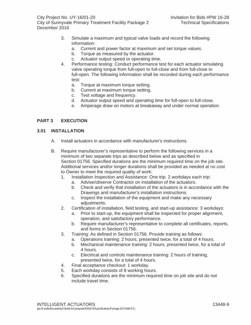
City Project No. UY-16/01-20 Invitation for Bids #PW 16-28City of Sunnyvale Primary Treatment Facility Package 2 Technical SpecificationsDecember 2016
INTELLIGENT ACTUATORS 13448-9 pw://Carollo/Documents/Client/CA/Sunnyvale/9265A10/Specifications/Package 02/13448 (FS)
3. Simulate a maximum and typical valve loads and record the following information:a. Current and power factor at maximum and set torque values.b. Torque as measured by the actuator.c. Actuator output speed or operating time.
4. Performance testing: Conduct performance test for each actuator simulating valve operating torque from full-open to full-close and from full-close to full-open. The following information shall be recorded during each performance test:a. Torque at maximum torque setting.b. Current at maximum torque setting. c. Test voltage and frequency.d. Actuator output speed and operating time for full-open to full-close.e. Amperage draw on motors at breakaway and under normal operation.
PART 3 EXECUTION
3.01 INSTALLATION
A. Install actuators in accordance with manufacturer's instructions.
B. Require manufacturer’s representative to perform the following services in a minimum of two separate trips as described below and as specified in Section 01756. Specified durations are the minimum required time on the job site. Additional services and/or longer durations shall be provided as needed at no cost to Owner to meet the required quality of work:1. Installation Inspection and Assistance: One trip. 2 workdays each trip:
a. Advise/observe Contractor on installation of the actuators. b. Check and verify that installation of the actuators is in accordance with the
Drawings and manufacturer’s installation instructions.c. Inspect the installation of the equipment and make any necessary
adjustments.2. Certification of installation, field testing, and start-up assistance: 3 workdays:
a. Prior to start-up, the equipment shall be inspected for proper alignment, operation, and satisfactory performance.
b. Require manufacturer’s representative to complete all certificates, reports, and forms in Section 01756.
3. Training: As defined in Section 01756. Provide training as follows:a. Operations training: 2 hours, presented twice, for a total of 4 hours.b. Mechanical maintenance training: 2 hours, presented twice, for a total of
4 hours.c. Electrical and controls maintenance training: 2 hours of training,
presented twice, for a total of 4 hours.4. Final acceptance checkout: 1 workday.5. Each workday consists of 8 working hours.6. Specified durations are the minimum required time on job site and do not
include travel time.
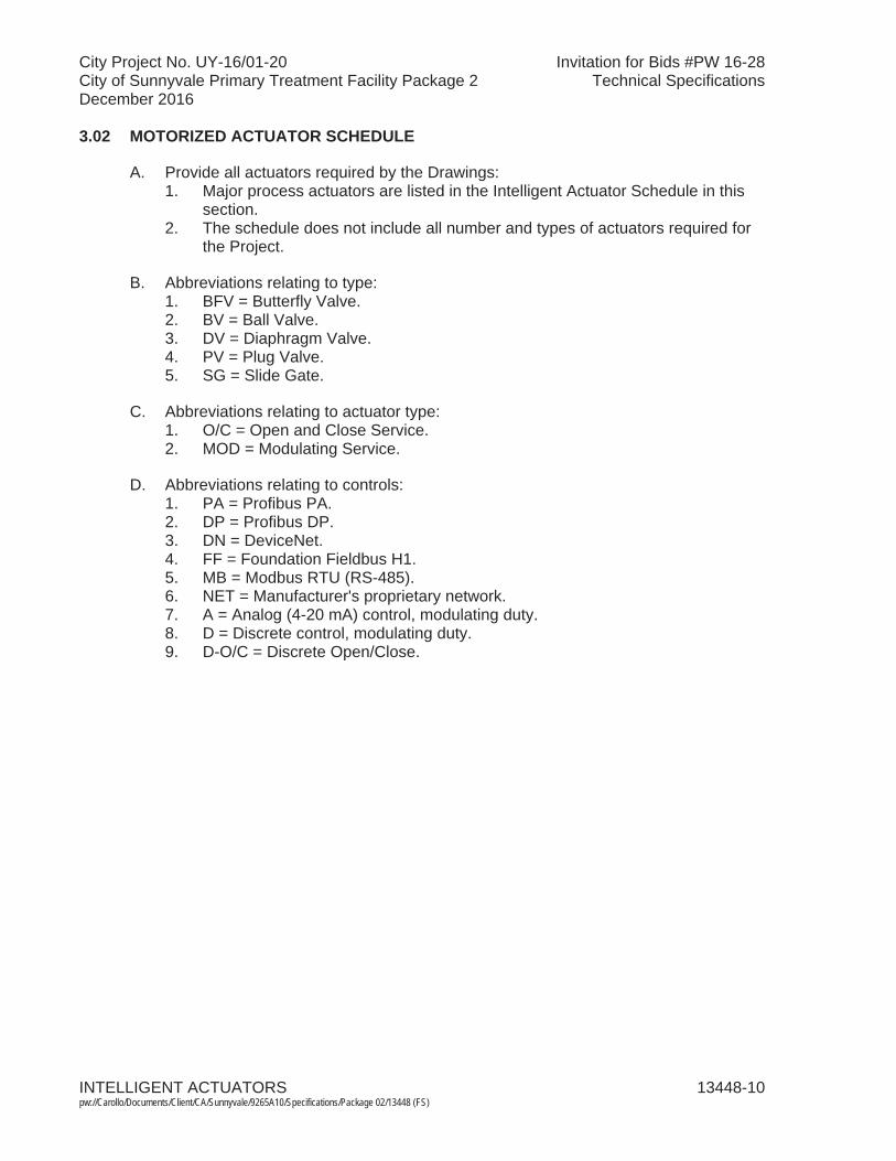
City Project No. UY-16/01-20 Invitation for Bids #PW 16-28City of Sunnyvale Primary Treatment Facility Package 2 Technical SpecificationsDecember 2016
INTELLIGENT ACTUATORS 13448-10pw://Carollo/Documents/Client/CA/Sunnyvale/9265A10/Specifications/Package 02/13448 (FS)
3.02 MOTORIZED ACTUATOR SCHEDULE
A. Provide all actuators required by the Drawings:1. Major process actuators are listed in the Intelligent Actuator Schedule in this
section. 2. The schedule does not include all number and types of actuators required for
the Project.
B. Abbreviations relating to type:1. BFV = Butterfly Valve.2. BV = Ball Valve.3. DV = Diaphragm Valve.4. PV = Plug Valve.5. SG = Slide Gate.
C. Abbreviations relating to actuator type:1. O/C = Open and Close Service.2. MOD = Modulating Service.
D. Abbreviations relating to controls:1. PA = Profibus PA.2. DP = Profibus DP.3. DN = DeviceNet.4. FF = Foundation Fieldbus H1.5. MB = Modbus RTU (RS-485).6. NET = Manufacturer's proprietary network.7. A = Analog (4-20 mA) control, modulating duty.8. D = Discrete control, modulating duty.9. D-O/C = Discrete Open/Close.
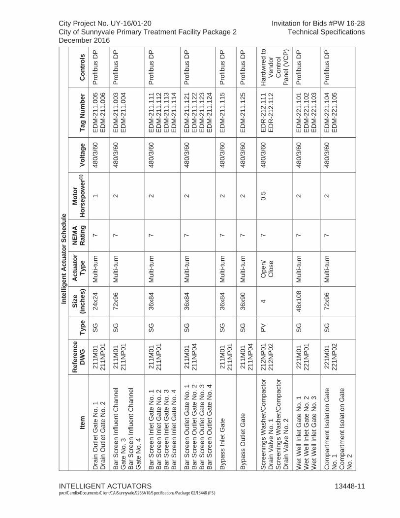
INTELLIGENT ACTUATORS 13448-11pw://Carollo/Documents/Client/CA/Sunnyvale/9265A10/Specifications/Package 02/13448 (FS)
City Project No. UY-16/01-20 Invitation for Bids #PW 16-28City of Sunnyvale Primary Treatment Facility Package 2 Technical SpecificationsDecember 2016
Inte
llige
ntA
ctua
tor S
ched
ule
Item
Ref
eren
ce
DW
GTy
peSi
ze(in
ches
)A
ctua
tor
Type
NEM
A
Rat
ing
Mot
orH
orse
pow
er(1
)Vo
ltage
Tag
Num
ber
Con
trol
s
Dra
in O
utle
t Gat
e N
o.1
Dra
in O
utle
t Gat
e N
o.2
211M
0121
1NP
01S
G24
x24
Mul
ti-tu
rn7
148
0/3/
60E
DM
-211
.005
ED
M-2
11.0
06P
rofib
us D
P
Bar
Scr
een
Influ
ent C
hann
el
Gat
e N
o. 3
B
ar S
cree
n In
fluen
t Cha
nnel
G
ate
No.
4
211M
0121
1NP
01S
G72
x96
Mul
ti-tu
rn7
2 48
0/3/
60E
DM
-211
.003
ED
M-2
11.0
04P
rofib
us D
P
Bar
Scr
een
Inle
t Gat
e N
o.1
Bar
Scr
een
Inle
t Gat
e N
o. 2
B
ar S
cree
n In
let G
ate
No.
3
Bar
Scr
een
Inle
t Gat
e N
o.4
211M
0121
1NP
01S
G36
x84
Mul
ti-tu
rn7
248
0/3/
60E
DM
-211
.111
ED
M-2
11.1
12E
DM
-211
.113
ED
M-2
11.1
14
Pro
fibus
DP
Bar
Scr
een
Out
let G
ate
No.
1B
ar S
cree
n O
utle
t Gat
e N
o. 2
B
ar S
cree
n O
utle
t Gat
e N
o. 3
B
ar S
cree
n O
utle
t Gat
e N
o.4
211M
0121
1NP
04S
G36
x84
Mul
ti-tu
rn7
248
0/3/
60E
DM
-211
.121
ED
M-2
11.1
22E
DM
-211
.123
ED
M-2
11.1
24
Pro
fibus
DP
Byp
ass
Inle
t Gat
e21
1M01
211N
P01
SG
36x8
4M
ulti-
turn
72
480/
3/60
EDM
-211
.115
Pro
fibus
DP
Byp
ass
Out
let G
ate
211M
0121
1NP
04S
G36
x90
Mul
ti-tu
rn7
248
0/3/
60ED
M-2
11.1
25P
rofib
us D
P
Scre
enin
gs W
ashe
r/Com
pact
orD
rain
Val
ve N
o. 1
Sc
reen
ings
Was
her/C
ompa
ctor
Dra
in V
alve
No.
2
212N
P01
212N
P02
PV4
Ope
n/C
lose
70.
548
0/3/
60E
DR
-212
.111
ED
R-2
12.1
12H
ardw
ired
to
Ven
dor
Con
trol
Pan
el (V
CP)
Wet
Wel
l Inl
et G
ate
No.
1W
et W
ell I
nlet
Gat
e N
o. 2
W
et W
ell I
nlet
Gat
e N
o.3
221M
0122
1NP
01S
G48
x108
Mul
ti-tu
rn7
248
0/3/
60E
DM
-221
.101
ED
M-2
21.1
02E
DM
-221
.103
Pro
fibus
DP
Com
partm
entI
sola
tion
Gat
e N
o. 1
C
ompa
rtmen
tIso
latio
n G
ate
No.
2
221M
0122
1NP
02S
G72
x96
Mul
ti-tu
rn7
248
0/3/
60E
DM
-221
.104
ED
M-2
21.1
05P
rofib
us D
P

INTELLIGENT ACTUATORS 13448-12pw://Carollo/Documents/Client/CA/Sunnyvale/9265A10/Specifications/Package 02/13448 (FS)
City Project No. UY-16/01-20 Invitation for Bids #PW 16-28City of Sunnyvale Primary Treatment Facility Package 2 Technical SpecificationsDecember 2016
Inte
llige
ntA
ctua
tor S
ched
ule
Item
Ref
eren
ce
DW
GTy
peSi
ze(in
ches
)A
ctua
tor
Type
NEM
A
Rat
ing
Mot
orH
orse
pow
er(1
)Vo
ltage
Tag
Num
ber
Con
trol
s
Pum
p In
take
Gat
e N
o.1
Pum
p In
take
Gat
e N
o. 2
P
ump
Inta
ke G
ate
No.
3
Pum
p In
take
Gat
e N
o. 4
P
ump
Inta
ke G
ate
No.
5
Pum
p In
take
Gat
e N
o.6
221M
0122
1NP
03S
G30
x30
Mul
ti-tu
rn7
248
0/3/
60E
DM
-221
.111
ED
M-2
21.1
21E
DM
-221
.131
ED
M-2
21.1
12E
DM
-221
.122
ED
M-2
21.1
32
Pro
fibus
DP
Grit
Bas
in In
let G
ate
No.
1G
rit B
asin
Inle
t Gat
e N
o. 2
G
rit B
asin
Inle
t Gat
e N
o. 3
231M
0323
1NP
0123
1NP
0223
1NP
03
SG
36x8
4M
ulti-
turn
71
480/
3/60
ED
M-2
31.1
11E
DM
-231
.121
ED
M-2
31.1
31
Pro
fibus
DP
Grit
Bas
in O
utle
t Gat
e N
o.1
231M
0323
1NP
01S
G42
x60
Mul
ti-tu
rn7
148
0/3/
60ED
M-2
31.3
11P
rofib
us D
P
Grit
Bas
in O
utle
t Gat
e N
o.2
Grit
Bas
in O
utle
t Gat
e N
o. 3
23
1M03
231N
P02
231N
P03
SG
42x6
0M
ulti-
turn
71
480/
3/60
ED
M-2
31.3
21E
DM
-231
.331
Pro
fibus
DP
Grit
Pum
p S
uctio
n V
alve
No.
1AG
rit P
ump
Suc
tion
Val
ve N
o.1B
Grit
Pum
p S
uctio
n V
alve
No.
2AG
rit P
ump
Suc
tion
Val
ve N
o.2B
Grit
Pum
p S
uctio
n V
alve
No.
3AG
rit P
ump
Suc
tion
Val
ve N
o.3B
231M
0123
1NP
0523
1NP
0623
1NP
07
PV
6M
ulti-
turn
70.
7548
0/3/
60E
DM
-231
.411
ED
M-2
31.4
12E
DM
-231
.421
ED
M-2
31.4
22E
DM
-231
.431
ED
M-2
31.4
32
Pro
fibus
DP
Grit
Bas
in D
rain
Val
ve N
o.1
Grit
Bas
in D
rain
Val
ve N
o. 2
G
rit B
asin
Dra
in V
alve
No.
3
231M
0123
1NP
0123
1NP
0223
1NP
03
PV
6M
ulti-
turn
70.
7548
0/3/
60E
DM
-231
.313
ED
M-2
31.3
23E
DM
-231
.333
Pro
fibus
DP
Grit
Bas
in F
ill V
alve
No.
1
Grit
Bas
in F
ill V
alve
No.
2
Grit
Bas
in F
ill V
alve
No.
3
231M
0123
1NP
0123
1NP
0223
1NP
03
PV
6 M
ulti-
turn
7 0.
7548
0/3/
60E
DM
-231
.312
ED
M-2
31.3
22E
DM
-231
.332
Pro
fibus
DP
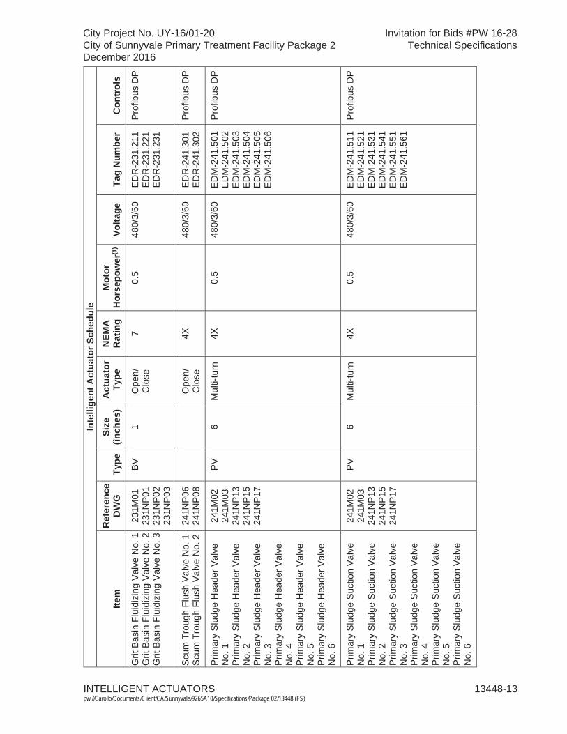
INTELLIGENT ACTUATORS 13448-13pw://Carollo/Documents/Client/CA/Sunnyvale/9265A10/Specifications/Package 02/13448 (FS)
City Project No. UY-16/01-20 Invitation for Bids #PW 16-28City of Sunnyvale Primary Treatment Facility Package 2 Technical SpecificationsDecember 2016
Inte
llige
ntA
ctua
tor S
ched
ule
Item
Ref
eren
ce
DW
GTy
peSi
ze(in
ches
)A
ctua
tor
Type
NEM
A
Rat
ing
Mot
orH
orse
pow
er(1
)Vo
ltage
Tag
Num
ber
Con
trol
s
Grit
Bas
in F
luid
izin
g V
alve
No.
1G
rit B
asin
Flu
idiz
ing
Val
ve N
o. 2
Grit
Bas
in F
luid
izin
g V
alve
No.
3
231M
0123
1NP
0123
1NP
0223
1NP
03
BV1
Ope
n/C
lose
70.
548
0/3/
60E
DR
-231
.211
ED
R-2
31.2
21E
DR
-231
.231
Pro
fibus
DP
Scu
m T
roug
h Fl
ush
Val
ve N
o.1
Scu
m T
roug
h Fl
ush
Val
ve N
o.2
241N
P06
241N
P08
Ope
n/C
lose
4X48
0/3/
60E
DR
-241
.301
ED
R-2
41.3
02P
rofib
us D
P
Prim
ary
Slu
dge
Hea
der V
alve
N
o. 1
P
rimar
y S
ludg
e H
eade
r Val
ve
No.
2
Prim
ary
Slu
dge
Hea
der V
alve
N
o. 3
P
rimar
y S
ludg
e H
eade
r Val
ve
No.
4
Prim
ary
Slu
dge
Hea
der V
alve
N
o. 5
P
rimar
y S
ludg
e H
eade
r Val
ve
No.
6
241M
0224
1M03
241N
P13
241N
P15
241N
P17
PV
6M
ulti-
turn
4X0.
548
0/3/
60E
DM
-241
.501
ED
M-2
41.5
02E
DM
-241
.503
ED
M-2
41.5
04E
DM
-241
.505
ED
M-2
41.5
06
Pro
fibus
DP
Prim
ary
Slu
dge
Suc
tion
Valv
e N
o. 1
P
rimar
y S
ludg
e S
uctio
n Va
lve
No.
2
Prim
ary
Slu
dge
Suc
tion
Valv
e N
o. 3
P
rimar
y S
ludg
e S
uctio
n Va
lve
No.
4
Prim
ary
Slu
dge
Suc
tion
Valv
e N
o. 5
P
rimar
y S
ludg
e S
uctio
n Va
lve
No.
6
241M
0224
1M03
241N
P13
241N
P15
241N
P17
PV
6M
ulti-
turn
4X0.
548
0/3/
60E
DM
-241
.511
ED
M-2
41.5
21E
DM
-241
.531
ED
M-2
41.5
41E
DM
-241
.551
ED
M-2
41.5
61
Pro
fibus
DP

INTELLIGENT ACTUATORS 13448-14pw://Carollo/Documents/Client/CA/Sunnyvale/9265A10/Specifications/Package 02/13448 (FS)
City Project No. UY-16/01-20 Invitation for Bids #PW 16-28City of Sunnyvale Primary Treatment Facility Package 2 Technical SpecificationsDecember 2016
Inte
llige
ntA
ctua
tor S
ched
ule
Item
Ref
eren
ce
DW
GTy
peSi
ze(in
ches
)A
ctua
tor
Type
NEM
A
Rat
ing
Mot
orH
orse
pow
er(1
)Vo
ltage
Tag
Num
ber
Con
trol
s
Ferr
ic C
hlor
ide
Tank
No.
1E
fflue
nt V
alve
Ferr
ic C
hlor
ide
Tank
No.
2E
fflue
nt V
alve
246M
0124
6NP
04BV
1O
pen/
Clo
se4X
0.5
480/
3/60
ED
R-2
46.2
11E
DR
-246
.221
Pro
fibus
DP
Not
es:
(1)
Mot
or h
orse
pow
er li
sted
in th
e In
telli
gent
Act
uato
r Sch
edul
e is
for r
efer
ence
onl
y. R
efer
to th
e D
raw
ings
for m
otor
hor
sepo
wer
info
rmat
ion.
M
otor
hor
sepo
wer
indi
cate
d on
the
Dra
win
gs fo
r the
act
uato
rs a
re m
inim
um re
quire
d ho
rsep
ower
. Sub
mit
calc
ulat
ions
and
dat
a to
su
bsta
ntia
te p
ropo
sed
mot
or h
orse
pow
er. I
f lar
ger m
otor
is re
quire
d, a
ll co
sts
rela
ted
to e
lect
rical
sys
tem
mod
ifica
tions
and
inst
alla
tions
sha
ll be
bor
ne b
y th
e C
ontra
ctor
.
EN
D O
F S
EC
TIO
N
City Project No. UY-16/01-20 Invitation for Bids #PW 16-28City of Sunnyvale Primary Treatment Facility Package 2 Technical SpecificationsDecember 2016
SHAFTLESS SCREW CONVEYOR SYSTEM 14555-1 pw://Carollo/Documents/Client/CA/Sunnyvale/9265A10/Specifications/Package 02/14555 (FS)
SECTION 14555
SHAFTLESS SCREW CONVEYOR SYSTEM
PART 1 GENERAL
1.01 SUMMARY
A. Section includes: Shaftless screw conveyor, associated slide gates with pneumatic actuators, screenings inlet and discharge chutes, supports, controls, and accessories:1. Equipment tag numbers:
a. Screenings Conveyor: CON-212.001. b. Conveyor Gate No. 1: GAT-212.011. c. Conveyor Gate No. 2: GAT-212.012.
B. Related sections:1. The Contract Documents are complementary; what is called for by one is as
binding as if called for by all.2. It is the Contractor's responsibility for scheduling and coordinating the Work of
subcontractors, suppliers, and other individuals or entities performing or furnishing any of Contractor's Work.
3. The following Sections are related to the Work described in this Section. This list of Related Sections is provided for convenience only and is not intended to excuse or otherwise diminish the duty of the Contractor to see that the completed Work complies accurately with the Contract Documents:a. Section 01010 - Summary of Work. b. Section 01340 - Shop Drawings, Product Data and Samples. c. Section 01600 - Product Requirements.d. Section 01610 - Project Design Criteria.e. Section 01612 - Seismic Design Criteria.f. Section 01614 - Wind Design Criteria.g. Section 01756 - Testing, Training, and Facility Start-Up.h. Section 01730 - Operations and Maintenance Data.i. Section 05120 - Structural Steel.j. Section 05500 - Metal Fabrications.k. Section 09960 - High-Performance Coatings. l. Section 11333 - Screenings Washer/Compactors.m. Section 13445A - Pneumatic Cylinder Operators.n. Section 15050 - Common Work Results for Mechanical Equipment. o. Section 15958 - Mechanical Equipment Testing.p. Section 16050 - Common Work Results for Electrical.q. Section 16222 - Low-Voltage Motors up to 500 Horsepower. r. Section 16422 - Motor Starters.s. Section 17050 - Common Work Results for Process Control and
Instrumentation Systems. t. Section 17100 - Control Strategies.
City Project No. UY-16/01-20 Invitation for Bids #PW 16-28City of Sunnyvale Primary Treatment Facility Package 2 Technical SpecificationsDecember 2016
SHAFTLESS SCREW CONVEYOR SYSTEM 14555-2 pw://Carollo/Documents/Client/CA/Sunnyvale/9265A10/Specifications/Package 02/14555 (FS)
u. Section 17101 - Specific Control Strategies. v. Section 17710 - Control Systems - Panels, Enclosures, and Panel
Components.w. Section 17950 - Testing, Calibration, and Commissioning.
C. All equipment shall conform to the requirements of Section 15050 except as modified herein.
1.02 REFERENCES
A. American Iron and Steel Institute (AISI).
B. American Bearing Manufacturers Association (ABMA):1. 9 - Load Ratings and Fatigue Life for Ball Bearings.2. 11 - Load Ratings and Fatigue Life for Roller Bearings.
C. American Gear Manufacturer's Association (AGMA).
D. American National Standards Institute/American Society of Mechanical Engineers (ANSI/ASME).
E. American Society for Testing and Materials (ASTM):1. A 48 - Standard Specification for Gray Iron Castings.2. A 108 - Standard Specification for Steel Bars, Carbon, Cold-Finished,
Standard Quality.3. A 276 - Standard Specification for Stainless and Heat Resisting Steel Bars and
Shapes.4. A 283 - Specification for Low and Intermediate Tensile Strength Carbon Steel
Plates.5. A 743 - Standard Specification for Castings, Iron-Chromium, Iron-Nickel,
Corrosion Resistant, for General Application.6. E 10 - Test Method for Brinell Hardness of Metallic Materials.
F. National Electrical Manufacturer's Association (NEMA).
1.03 SYSTEM DESCRIPTION
A. General:1. One inclined shaftless screw conveyor to collect and transport municipal raw
screenings, complete with all accessories and controls necessary to provide a complete, operational system in accordance with the Contract Documents.
2. The shaftless screw conveyor system equipment shall include, but not be limited to, the following items, all of which shall be supplied by the conveyor manufacturer:a. Spiral flighting.b. Drive.c. Trough and liner.d. Covers.e. Flexible and rigid discharge chutes.
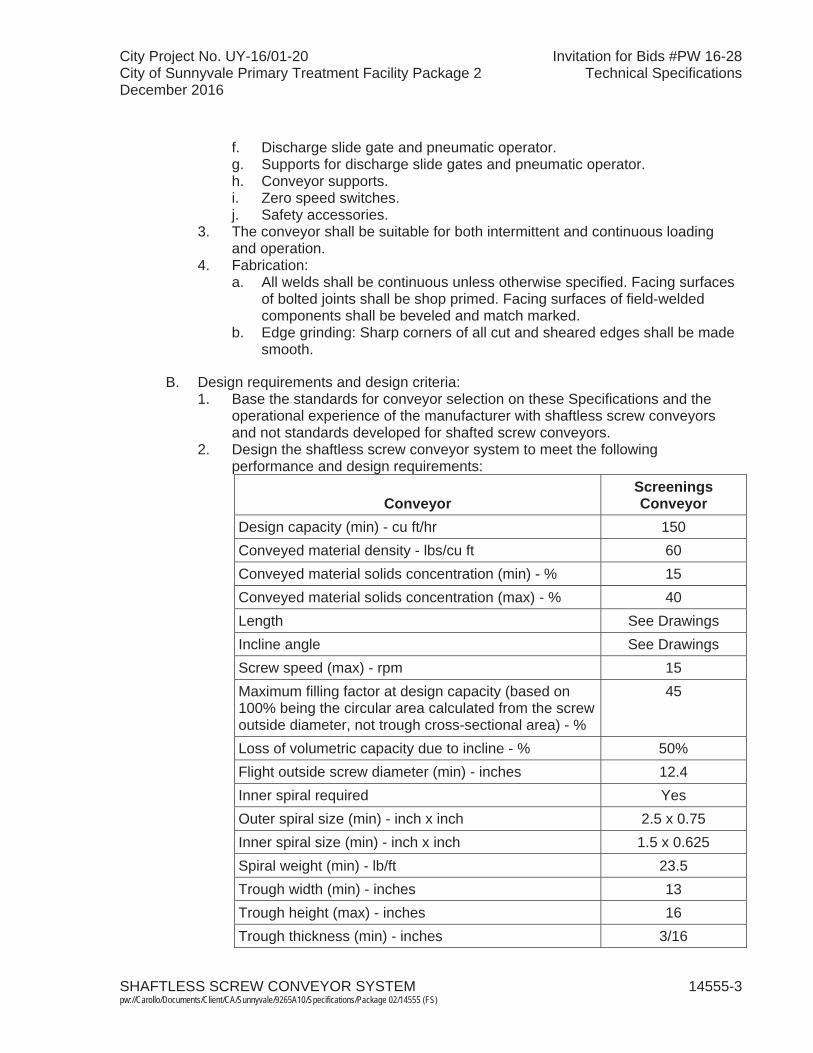
City Project No. UY-16/01-20 Invitation for Bids #PW 16-28City of Sunnyvale Primary Treatment Facility Package 2 Technical SpecificationsDecember 2016
SHAFTLESS SCREW CONVEYOR SYSTEM 14555-3 pw://Carollo/Documents/Client/CA/Sunnyvale/9265A10/Specifications/Package 02/14555 (FS)
f. Discharge slide gate and pneumatic operator. g. Supports for discharge slide gates and pneumatic operator.h. Conveyor supports.i. Zero speed switches.j. Safety accessories.
3. The conveyor shall be suitable for both intermittent and continuous loading and operation.
4. Fabrication:a. All welds shall be continuous unless otherwise specified. Facing surfaces
of bolted joints shall be shop primed. Facing surfaces of field-welded components shall be beveled and match marked.
b. Edge grinding: Sharp corners of all cut and sheared edges shall be made smooth.
B. Design requirements and design criteria:1. Base the standards for conveyor selection on these Specifications and the
operational experience of the manufacturer with shaftless screw conveyors and not standards developed for shafted screw conveyors.
2. Design the shaftless screw conveyor system to meet the following performance and design requirements:
ConveyorScreenings Conveyor
Design capacity (min) - cu ft/hr 150Conveyed material density - lbs/cu ft 60Conveyed material solids concentration (min) - % 15Conveyed material solids concentration (max) - % 40Length See DrawingsIncline angle See DrawingsScrew speed (max) - rpm 15Maximum filling factor at design capacity (based on 100% being the circular area calculated from the screw outside diameter, not trough cross-sectional area) - %
45
Loss of volumetric capacity due to incline - % 50%Flight outside screw diameter (min) - inches 12.4Inner spiral required Yes Outer spiral size (min) - inch x inch 2.5 x 0.75Inner spiral size (min) - inch x inch 1.5 x 0.625 Spiral weight (min) - lb/ft 23.5Trough width (min) - inches 13Trough height (max) - inches 16Trough thickness (min) - inches 3/16
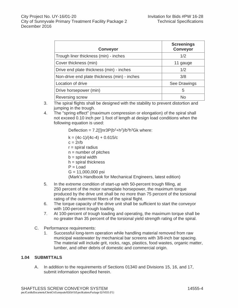
City Project No. UY-16/01-20 Invitation for Bids #PW 16-28City of Sunnyvale Primary Treatment Facility Package 2 Technical SpecificationsDecember 2016
SHAFTLESS SCREW CONVEYOR SYSTEM 14555-4 pw://Carollo/Documents/Client/CA/Sunnyvale/9265A10/Specifications/Package 02/14555 (FS)
ConveyorScreenings Conveyor
Trough liner thickness (min) - inches 1/2Cover thickness (min) 11 gaugeDrive end plate thickness (min) - inches 1/2Non-drive end plate thickness (min) - inches 3/8Location of drive See DrawingsDrive horsepower (min) 5 Reversing screw No
3. The spiral flights shall be designed with the stability to prevent distortion and jumping in the trough.
4. The "spring effect" (maximum compression or elongation) of the spiral shall not exceed 0.10 inch per 1 foot of length at design load conditions when the following equation is used:
Deflection = 7.2 nr3P(b2+h2)/b3h3Gk where:
k = (4c-1)/(4c-4) + 0.615/cc = 2r/br = spiral radiusn = number of pitchesb = spiral widthh = spiral thicknessP = LoadG = 11,000,000 psi(Mark's Handbook for Mechanical Engineers, latest edition)
5. In the extreme condition of start-up with 50-percent trough filling, at 250 percent of the motor nameplate horsepower, the maximum torque produced by the drive unit shall be no more than 75 percent of the torsional rating of the outermost fibers of the spiral flight.
6. The torque capacity of the drive unit shall be sufficient to start the conveyor with 100-percent trough loading.
7. At 100-percent of trough loading and operating, the maximum torque shall be no greater than 35 percent of the torsional yield strength rating of the spiral.
C. Performance requirements:1. Successful long-term operation while handling material removed from raw
municipal wastewater by mechanical bar screens with 3/8-inch bar spacing. The material will include grit, rocks, rags, plastics, food wastes, organic matter, lumber, and other debris of domestic and commercial origin.
1.04 SUBMITTALS
A. In addition to the requirements of Sections 01340 and Divisions 15, 16, and 17,submit information specified herein.
City Project No. UY-16/01-20 Invitation for Bids #PW 16-28City of Sunnyvale Primary Treatment Facility Package 2 Technical SpecificationsDecember 2016
SHAFTLESS SCREW CONVEYOR SYSTEM 14555-5 pw://Carollo/Documents/Client/CA/Sunnyvale/9265A10/Specifications/Package 02/14555 (FS)
B. Installation list:1. To verify conformance with the specified Manufacturer Qualifications as
specified in Article 1.05. 2. Include the following information as a minimum:
a. Name and location of installation.b. Name and telephone number of person in direct responsible charge of the
equipment.c. Month and year the equipment was placed in operation.d. Size of equipment: Length and diameter of shaftless screw.e. Design capacity and corresponding filling factor.f. Indicate whether single or double (outer plus inner) spiral was used.g. Manufacturer of spiral.h. Conveyor incline angle.i. Location of drive: Push or pull system.j. Drive horsepower.k. Number of units installed.l. Service and material conveyed.m. Liner material.
C. Product Data.
D. Shop drawings:1. Detailed dimensional arrangement drawings of the complete screw conveyor
assemblies including locations of conveyors relative to each other and relative locations of associated feed hoppers, inlet and outlet chutes, slide gates, diverter gate, and conveyor supports:a. Verify conformance to the dimensional constraints shown on the
Drawings.b. Provide detailed dimensional arrangement drawings.
2. Detailed drawings of system components including screw conveyors, motors, gear reducers, chutes, diverter gates, slide gates and operators, hoppers, supports, instrumentation, and accessories.
3. Show locations of trough liner joints to verify conformance to special requirements indicated in the Contract Drawings.
E. Separate certification from the spiral manufacturer certifying that the spiral meets the minimum specified hardness and yield strength requirements and is crack free as determined by a dye-penetrant examination.
F. Certification from the conveyor manufacturer certifying that the overall conveyor gate design, including gate size, orientation, configuration and seal design, represents a highly robust design for the conveyor gates in the intended application and will provide water tight seals when in closed position in all anticipated operational scenarios.
G. Should the conveyor manufacturer not fabricate spirals, then a dye test must be performed and its results must be submitted.
H. Complete Bill of Materials with part numbers.

City Project No. UY-16/01-20 Invitation for Bids #PW 16-28City of Sunnyvale Primary Treatment Facility Package 2 Technical SpecificationsDecember 2016
SHAFTLESS SCREW CONVEYOR SYSTEM 14555-6 pw://Carollo/Documents/Client/CA/Sunnyvale/9265A10/Specifications/Package 02/14555 (FS)
I. Calculations: Detailed calculations and design data verifying conformance with theDrawings and Specifications:1. Structural calculations: Include the following to support structural adequacy of
the conveyors and accessories, prepared and signed by a registered professional structural engineer in the State of California:a. Conveyor supports including member sizing and anchoring to concrete
slabs in accordance with the Drawings. Support calculations shall also confirm compliance with the design criteria specified in Article 2.03Paragraph D.
b. Support design for chutes, slide gates, and motorized operators.c. Seismic design as specified in Section 01612 and wind design criteria as
specified in Section 01614. 2. Mechanical calculations prepared and signed by a registered professional
mechanical engineer to demonstrate the following:a. Volumetric capacity of each conveyor.b. Torque calculations and selection of the gear reducer size and motor
horsepower.c. Compliance with each of the design requirements specified in Article 1.03
Paragraph B, and Article 2.03 Paragraph E, and Section 15050.
J. Manufacturer's Installation Instructions.
K. Motor data per Section 16222.
L. Quality control submittals:1. Detailed performance test procedures: Source quality control and field testing.2. Performance test data including measured leakage rates of conveyor gates. 3. Provide Manufacturer's Certificate of Source Testing as specified in
Section 01756 and this Section.4. Provide Manufacturer's Certificate of Installation and Functionality Compliance
as specified in Section 01756.
M. Operation and Maintenance Manual per Section 01730.
N. Wiring Schematics.
O. Technician Qualifications Resume: Submit resume of technician(s) to perform manufacturer's field services.
1.05 QUALITY ASSURANCE
A. As specified in Section 15050.
B. Manufacturer qualifications:1. Minimum 10-years of experience in construction and manufacturing of
shaftless screw conveyor systems substantially similar to the specified equipment for the municipal wastewater treatment industry. The installation or reselling of shaftless screw conveyors shall not qualify as construction or manufacturing experience and will not be considered towards meeting the experience requirements.
City Project No. UY-16/01-20 Invitation for Bids #PW 16-28City of Sunnyvale Primary Treatment Facility Package 2 Technical SpecificationsDecember 2016
SHAFTLESS SCREW CONVEYOR SYSTEM 14555-7 pw://Carollo/Documents/Client/CA/Sunnyvale/9265A10/Specifications/Package 02/14555 (FS)
2. The manufacturer shall have completed and made operational not less than 20 separate installations of shaftless screw conveyors of similar size, type, and service as this project, in municipal wastewater application in the United States, with not less than 10-years of successful operating experience.Multiple conveyors at a plant shall be considered as one installation toward meeting the experience requirements.
3. Installation list: Submit evidence of satisfactory operation of equipment similar to the specified equipment in at least 20 separate facilities in North America in accordance with the following requirements:a. All equipment on the submitted installation list shall:
1) Be in municipal wastewater industry application.2) Have the same spiral manufacturer and screw conveyor system
manufacturer as proposed for this project.3) Have a minimum spiral diameter of 10 inches.4) Have a minimum spiral length of 30 feet.5) Be a conveyor separate from a compactor unit.
b. At least 3 of the installations shall also satisfy the following requirements:1) Years of successful operating experience: Minimum 5 years.2) Service: Municipal screenings.3) Spiral: Double, consisting of an outer and inner spiral.4) Incline: 15 degrees minimum.5) Spiral length: Minimum 45 feet.6) Spiral diameter: Minimum 12 inches.
c. Multiple equipment units at a plant shall be considered as one installation toward meeting the experience requirements.
C. Fulfillment of the specified experience requirements shall be a condition of acceptance.
D. The gear reducer/motor drive unit shall be manufactured in the U.S.
E. Manufacturer's Shop Welds, Welding Procedures, and Welders: Qualified and certified in accordance with the requirements of ANSI/AWS D1.1, or ASME Boiler and Pressure Vessel Code Section IX.
F. Screw Conveyor System: Shop inspected, assembled, adjusted, and tested for proper fit before shipping.
1.06 DELIVERY, STORAGE, AND HANDLING
A. Shaftless screw conveyor system:1. Factory assembled before shipment to ensure proper fit of all components.2. Ship equipment in the minimum practical number of pieces for field assembly
by the Contractor. 3. Follow the requirements of Sections 01010 and 15050.

City Project No. UY-16/01-20 Invitation for Bids #PW 16-28City of Sunnyvale Primary Treatment Facility Package 2 Technical SpecificationsDecember 2016
SHAFTLESS SCREW CONVEYOR SYSTEM 14555-8 pw://Carollo/Documents/Client/CA/Sunnyvale/9265A10/Specifications/Package 02/14555 (FS)
1.07 PROJECT CONDITIONS
A. As specified in Section 01610.
B. Area classification:1. All devices and components mounted on the conveyor or conveyor assembly
shall be suitable for Class 1, Division 1, Group D hazardous locations,including components on the pneumatic actuators for the slide gates.
1.08 WARRANTY
A. Warrant equipment as specified in Section 01740.
B. Warranty shall cover parts and labor except for normal wear of the trough liner: 1. Screw: Excessive wear on the screw shall be indicated by loss of more than
50 percent of the height of the main outer screw section over 30 percent of the total length of the screw. If excessive wear is found, the conveyor supplier shall provide a new screw.
2. Trough Liner: For a wear indicator (i.e., two color) liner, excessive wear shall be indicated by the appearance of the bottom indicator layer (second color) along with more than 30 percent of the conveyor length during the first 3 years of service. In such event, the conveyor supplier shall provide new formed and banded liner to replace all liner sections that display excessive wear.
3. Conveyor Gate Seals: Warrant that the seals of the conveyor gates will provide water tight seals during the first 3 years of service in the intended application.
1.09 MAINTENANCE
A. Spare Parts: Furnish the following spare parts packed and labeled for warehouse storage in accordance with Section 15050.
Item QuantityTrough Liners 1 set
Gear Reducer and Motor Drive Unit 1
Shaft Seals 1 set of all shaft seals
B. Special Tools: Furnish any special tools required for maintenance and disassembly of furnished equipment.
City Project No. UY-16/01-20 Invitation for Bids #PW 16-28City of Sunnyvale Primary Treatment Facility Package 2 Technical SpecificationsDecember 2016
SHAFTLESS SCREW CONVEYOR SYSTEM 14555-9 pw://Carollo/Documents/Client/CA/Sunnyvale/9265A10/Specifications/Package 02/14555 (FS)
PART 2 PRODUCTS
2.01 MANUFACTURERS
A. One of the following, modified as necessary to meet the Specification requirements:1. Spirac Incorporated, Newnan, GA, Model U-355. 2. Custom Conveyor, Model CEMA 12". 3. Or equal.
B. If Contractor wishes to furnish "or equal" equipment that meets all specification requirements, then Contractor shall propose the "or-equal" as an alternative and obtain written approval from Owner. Should Owner grant said approval, all costs associated with modifications to adapt facilities as designed, to accommodate the proposed substitute equipment shall be borne by Contractor. This shall include all design, procurement, and installation costs for any necessary structural, mechanical, electrical, instrumentation and control, and any other changes required for a complete and satisfactory installation, including Engineer's redesign cost.
2.02 MATERIALS
A. Trough: AISI Type 316L stainless steel.
B. Drive and End Plates: AISI Type 316L stainless steel.
C. Covers: AISI Type 316L stainless steel.
D. Spiral Flights (certified by manufacturer): Cold-formed chrome alloy steel, Brinell 225 hardness (minimum), 80,000-psi yield strength (minimum), with inner and outer spirals.
E. Wear Liner: Ultra-high molecular weight polyethylene (UHMWPE) impregnated with a lubricating agent for increased anti-wearing:1. Density: 59 pounds per cubic foot, minimum.2. Hardness: 62 Shore D, minimum.
F. Chutes, Hoppers: AISI Type 316L stainless steel.
G. Supports: AISI Type 316L stainless steel.
H. Hardware, Fasteners, Lifting Lugs: Type 316 stainless steel.
I. Drive Shaft: AISI 1045.
2.03 SHAFTLESS SCREW CONVEYOR COMPONENTS
A. Spiral: 1. Design spiral flighting to convey material without a center shaft and with the
stability to prevent distortion and jumping in the trough.2. Spiral flighting shall consist of an outer spiral and an inner spiral to increase
conveyor axial strength and capacity. A third backing spiral may be used to achieve specified design requirements. Minimum spiral sizes and weight shall
City Project No. UY-16/01-20 Invitation for Bids #PW 16-28City of Sunnyvale Primary Treatment Facility Package 2 Technical SpecificationsDecember 2016
SHAFTLESS SCREW CONVEYOR SYSTEM 14555-10pw://Carollo/Documents/Client/CA/Sunnyvale/9265A10/Specifications/Package 02/14555 (FS)
be as specified herein. Also, neither the outer nor inner spiral shall exceed 3 inches in width. Single spirals of any size will not be accepted.
3. Spiral flights shall be cold-formed in sections from continuous flat hot-rolled bar with 80,000-psi minimum yield strength and 225 minimum Brinell measured anywhere on the spiral. Sectional flighting formed from plate will not be accepted.
4. Spiral flighting shall be concentric to within ±2 millimeters.5. Spirals shall be rolled in such a way as to limit "neckdown" of the outside edge
of the cold rolled spiral to 10 percent thickness of the inside edge of spiral. Spiral edges and faces shall be smooth in the as-rolled condition and not show cracks, roll forming, or grinding marks.
6. If any form of hold-down is required, provide such a hold-down using liner under the lid. The use of hold-down bars will not be accepted.
7. Spiral connections shall be welded according to AISC B-U3-GF (double V-groove) and be full-penetration welds. Flights shall be welded in a jig to ensure true alignment.
8. Connection of spiral to drive system shall be via a properly reinforced flanged connection plate welded to the spiral to form a smooth and continuous transformation from flange plate to spiral. Drive shaft shall have a mating flange and be bolted to spiral connection plate. Pipe connections will not be accepted. Additionally, a grease lubricated labyrinth seal shall be shaft mounted internally in the conveyor between the back plate and spiral coupling connection.
9. A gland packing ring consisting of two Teflon®-coated packing rings shall seal the drive shaft at its penetration through the end plate, along with a greased labyrinth sealing system.
10. Conveyor manufacturer shall provide a separate Spiral Certification from spiral manufacturer certifying that spiral meets minimum hardness and yield strength requirements and is crack free as determined by a dye-penetrant examination.
B. Trough and Cover:1. Trough shall be similar to dimensional standards of CEMA 300. Trough size,
thickness, and material shall be as specified herein.2. Trough shall be U-shaped with stiffeners across the top, fastened to both sides
of trough to maintain trough shape and act as a face seal for each cover section. At filling openings, provide a trough stiffener on each side of openingand no stiffeners across the opening.
3. Apply a continuous neoprene gasket totaling 1/2-inch width to the entire top face of the trough top flange and stiffeners.
4. Trough sections shall be joined using bolted flanged connections and neoprene gaskets.
5. Equip each trough with filling and/or discharge openings as indicated onDrawings. Each filling and discharge opening shall be flanged, suitable for connection to other devices such as slide gates, chutes, and hoppers:a. Discharge openings from conveyors shall have a length not less than
1.5 times the spiral pitch.b. Discharge openings from conveyors shall have a width equal to or wider
than the full width of the U-trough.
City Project No. UY-16/01-20 Invitation for Bids #PW 16-28City of Sunnyvale Primary Treatment Facility Package 2 Technical SpecificationsDecember 2016
SHAFTLESS SCREW CONVEYOR SYSTEM 14555-11pw://Carollo/Documents/Client/CA/Sunnyvale/9265A10/Specifications/Package 02/14555 (FS)
6. Flare the trough immediately above the top of liner at the locations of filling chutes where indicated on the Drawings for transfer from one conveyor to another.
7. Provide a 4-inch flanged drain outlet located at the end plate (at the low point): a. The invert of the drain outlet shall not be higher than 3 inches from the
bottom of the trough.8. The portion of each trough that is not covered by a filling chute shall be
covered by a bolted cover of a material identical to the trough.9. Cover sections shall be 5-foot length, maximum.10. Covers shall be bolted at maximum 12-inch spacing. For 5-foot covers, a
minimum of 6 bolts shall be provided. To prevent unsafe access to the conveyors, quick opening covers will not be accepted.
11. Where indicated on the Drawings, provide covers with stainless steel hinged observation hatches. At each hatch location, provide the cover with a stainless steel mesh guard to block access to the spiral.
12. Locate the following flanged pipe connections on the covers where indicated on the Drawings. Coordinate with Contractor on the required flange style and bolt pattern.a. 8-inch flanged port for connection with foul air piping.
C. Trough Liner:1. Provide the conveyor trough with a wear liner fabricated of UHMWPE
impregnated with a lubricating agent.2. Wear liner thickness shall be as specified herein.3. The liner shall be provided with a visual indication (using colors) of excess wear.4. Wear liner coefficient of thermal expansion shall match that of the trough
material.5. Wear liner shall be the following type, or equal:
a. DURAFLO SPX by SPIRAC, Inc.b. Xylethon by DuraWear Corporation.c. Custom Polystone M.
6. The wear liner shall be furnished in maximum 4-foot long sections. Shorter liner sections will be required at some locations to provide liner joints at specific locations. Indicate such locations in the shop drawings for approval.
7. Each liner section shall be held in place with a minimum of four Type 316L stainless steel retainer bars permanently welded to the trough at 180 degrees along the trough. Fasteners that penetrate the trough will not be accepted.
D. Supports:1. Provide conveyor supports fabricated of Type 316L stainless steel structural
members. The support types and configurations shall be as shown on the Drawings. The conveyor manufacturer shall be responsible for sizing the support structural members and anchors and shall include all required bracing to meet the application and Specifications requirements. For support design, assume the conveyor trough is 100-percent full with material weighing 60 lb/cf.
2. All structural supporting members shall be designed such that the ratio of the unbraced length to least radius of gyration (slenderness ratio) shall not exceed
City Project No. UY-16/01-20 Invitation for Bids #PW 16-28City of Sunnyvale Primary Treatment Facility Package 2 Technical SpecificationsDecember 2016
SHAFTLESS SCREW CONVEYOR SYSTEM 14555-12pw://Carollo/Documents/Client/CA/Sunnyvale/9265A10/Specifications/Package 02/14555 (FS)
120 for any compression member and shall not exceed 240 for any tension member (of angles about Z-Z axis).
3. All structural members and connections shall be designed so that the unit stresses will not exceed the American Institute of Steel Construction (AISC) allowable stresses by more than 1/3 when subject to loading of twice the maximum design operating torque of the spiral conveyor drive motors.
4. Provide supports for conveyor gates and their pneumatic actuators.5. At a minimum, each conveyor shall be provided with supports at each end,
with intermediate supports as shown on the Drawings. If required, provide additional supports as determined by the calculations.
6. Design the supports to avoid interference with other equipment or equipment supports. Supports shall not impede access for maintenance activities for other equipment.
7. Conveyor support spacing shall not exceed 10 feet.8. Supports shall be shop fabricated, assembled, fitted to the conveyor, and
match marked with the associated conveyor segments prior to shipment to the job site.
9. All shop welding shall conform to the latest standards of the American Welding Society (AWS).
E. Drive:1. Each spiral conveyor shall be driven by a constant-speed integral gear
reducer/motor drive unit mounted to an adapter flange, which is in turn mounted to the end plate of the conveyor.
2. The adapter flange shall allow the leakage of any material from the conveyor trough to the atmosphere rather than into the gear reducer/motor drive unit. Direct coupling of the gear reducer/motor drive unit to the end flange of the conveyor will not be accepted.
3. The drive unit shall be rigidly supported so there is no visible "wobble"movement under any operating condition.
4. The drive system shall be designed, at a minimum, to start the conveyor from a dead stop with the trough filled throughout its entire cross-sectional area and length with partially dried and hardened dewatered material.
5. The drive unit shall be a hollow shaft-mounted drive.6. Gear reducers:
a. All gears shall be AGMA Class II, single, double, or triple reduction, helical gear units with high-capacity roller bearings.
b. Bearings shall be designed for the thrust loads from the fully loaded start-up condition and shall have an AFBMA B10 life of 30,000 hours minimum.
c. V-belt driven speed reducers or chain-driven reducers will not be accepted.
d. The reducer shall be a standard air-cooled unit with no auxiliary cooling required.
e. The gear reducer shall be sized with a torque service factor of 1.5 times the absorbed power or 1.1 times the motor nameplate, at the driven shaft speed, whichever is greater.
City Project No. UY-16/01-20 Invitation for Bids #PW 16-28City of Sunnyvale Primary Treatment Facility Package 2 Technical SpecificationsDecember 2016
SHAFTLESS SCREW CONVEYOR SYSTEM 14555-13pw://Carollo/Documents/Client/CA/Sunnyvale/9265A10/Specifications/Package 02/14555 (FS)
7. Motor:a. Motor shall be as specified in Section 16222 except as modified herein.b. Constant speed: 480 V, 60 Hz, 3 phase.c. Maximum speed (nominal): 1,800 rpm.d. Enclosure: Suitable for Class 1, Division 1, Group D hazardous locations.
8. Drive unit shall be manufactured by Nord, SEW Eurodrive; or equal.
2.04 CHUTES AND HOPPERS
A. This article applies to the screenings inlet and outlet chutes.
B. Fabricated and provided by the conveyor system manufacturer.
C. Fabricated from the same material as the conveyor trough. Stainless steel shall be pickled and passivated.
D. Construct of 3/16-inch wall thickness with 1/4-inch flanges for connection to conveyors and/or other chute sections. Provide chutes with external body reinforcing stiffeners as required.
E. Provide neoprene gaskets at flanged connections.
F. Where indicated on Drawings, provide chutes with stainless steel hinged observation hatches. At each hatch, provide a stainless steel mesh guard to block access to the spiral.
G. Provide each chute section with handles and lifting lugs for easy handling.
H. Where indicated on Drawings, provide chute sections that are flexible connectors. Attach flexible connectors to mating flanges using stainless steel backing plates. Use of clamps to attach flexible components will not be accepted.1. Flexible Connectors:
a. Alternative 11) Top and bottom flanges: Type 316 stainless steel.2) Utilize neoprene impregnated canvas fixed to the flanges with 316
backing rings.3) Length as required to connect the slide gate to the plate on the
compactor hopper that has a flanged opening.b. Alternative 2
1) 18 ounces per square yard heavy-duty nylon scrim reinforced vinyl.2) Material shall be water repellent, flame retardant, mildew and acid
resistant.3) All hems shall be doubled reinforced and 2 inches thick with fabric
folded over to the outside to prevent material accumulation.4) Length as required to connect the slide gate to the plate on the
compactor hopper that has a flanged opening. 5) Individual chutes shall attach to each other and the bottom of slide
gate frame using stainless steel retaining strips attached through the hem. All retaining strips shall have the same bolt hole pattern.

City Project No. UY-16/01-20 Invitation for Bids #PW 16-28City of Sunnyvale Primary Treatment Facility Package 2 Technical SpecificationsDecember 2016
SHAFTLESS SCREW CONVEYOR SYSTEM 14555-14pw://Carollo/Documents/Client/CA/Sunnyvale/9265A10/Specifications/Package 02/14555 (FS)
2. Provide a 316 stainless steel plate cover for installation on top of the receiving compactor hopper. The plate shall have a rectangular flanged opening that matches the size and bolt pattern of the slide gate flange, such that a rectangular flexible connector may be used to connect the slide gate to the compactor hopper below.a. Round edges and corners of the plate for safe handling. b. Coordinate the overall plate size with the compactor manufacturer
specified in Section 11333.c. Provide four handles on each plate cover to allow two people to lift and
install the plates.d. Maximum weight of plate cover: 60 pounds.
3. Provide chutes with supports as required and as shown on the Drawings. Include chute support calculations with submittal for review by the Engineer.
I. Provide additional discharge chutes as indicated on the Drawings.
2.05 SLIDE GATES
A. Provide conveyor with slide gate at location and in configuration shown on the Drawings. Install slide gates level, whether the conveyor is inclined or not.
B. The slide gate shall be specifically designed to operate as an integral part of the conveyor system and shall be supplied by the conveyor manufacturer.1. Manufacturer: One of the following.
a. DeZurik, Hilton H-200-R b. SPIRAC USA Inc., UHMW Slide Gatec. Customer Conveyor Corporation, SPE gated. Substitution will not be allowed.
2. Type: Knife gate valves; fabricated, rectangular, closed bonnet style with flanged ends.
3. Materials:a. Valve body and blade: AISI 316 stainless steel.b. Valve blade guides: AISI 316 stainless steel.c. Valve blade seat: EPDM, Neoprene, or UHMWPE.
4. Opening dimensions:a. Length: Minimum 1.5 spiral pitches.b. Width: Full width of conveyor trough at the minimum.
5. Blade:a. Thickness as required to handle product head pressure without deflection
in the amount to cause binding on the guides and seals.b. The blade shall close to form and maintain a watertight seal. The use of
grease or other periodically applied material to form a watertight seal is not acceptable.
6. Gate bonnet:a. Seal at actuator rod, stem, or drive shaft openings to contain any gate
blade leakage from atmosphere.b. Seal rising stems or rotating shafts with adjustable packing glands or
spring loaded radial shaft lip seals.
City Project No. UY-16/01-20 Invitation for Bids #PW 16-28City of Sunnyvale Primary Treatment Facility Package 2 Technical SpecificationsDecember 2016
SHAFTLESS SCREW CONVEYOR SYSTEM 14555-15pw://Carollo/Documents/Client/CA/Sunnyvale/9265A10/Specifications/Package 02/14555 (FS)
c. Bonnet shall allow for blade seal leakage to be drained from the bonnet.Provide a 2-inch diameter flanged or threaded connection for the drain.Also provide a minimum 1-inch diameter flanged or threaded connection on the bonnet for flushing the bonnet and the drain.
d. Bonnet shall allow access to blade and guides in retraction area via complete removal of the flanged bonnet or access cover.
7. Design knife gate valves for a maximum installed vertical dimension of 6.5 inches excluding the actuator and its accessories.
C. Support slide gates and associated operators from the conveyor.
D. Gate actuation shall be by pneumatic operator as specified in Section 13445A: 1. Gate stem rod shall be clevis-mounted to the slide gate blade.2. Size cylinder to provide sufficient force to open the gate under full trough load.3. Provide open/close service with limit switches that are integral to the actuator.
2.06 CONTROLS
A. All devices mounted on the conveyor or within the hazardous area envelope shall be rated for Class 1, Division 1, Group D hazardous locations.
B. Refer to Division 16 and Division 17 for additional instrumentation and electrical requirements.
C. Provide field-mounted local control station including the following:1. NEMA 7 enclosure in accordance with Section 17710. 2. LOCAL-OFF-REMOTE selector switch:
a. In LOCAL, the conveyor is controlled by the START-STOP pushbuttons. b. In OFF, the conveyor shall be off.c. In REMOTE, all local controls with the exception of the Emergency Stop
mushroom pushbutton and cable switch shall be inhibited, and the conveyor shall be controlled from SCADA.
3. START-STOP pushbuttons.
D. Control Voltage: 120 volt, single phase.
E. Zero speed switch:1. Provide a zero speed switch located and mounted per the manufacturer's
recommendations and as indicated on the Drawings.2. Non-contacting type using a probe with a pre-amplifier and main electronic
assembly.3. Main electronic unit to operate on a 120-volt, single-phase, 60-Hertz power
supply.4. Suitable for installation in Class I, Division 1, Group D hazardous areas.5. As manufactured by Milltronics Model XPP 5 probe and MFA-4P controller or
equal with cabling and mounting kit as required for a completing working system.

City Project No. UY-16/01-20 Invitation for Bids #PW 16-28City of Sunnyvale Primary Treatment Facility Package 2 Technical SpecificationsDecember 2016
SHAFTLESS SCREW CONVEYOR SYSTEM 14555-16pw://Carollo/Documents/Client/CA/Sunnyvale/9265A10/Specifications/Package 02/14555 (FS)
F. Emergency STOP cable switch:1. Furnish each conveyor with two cable-operated latching type emergency
STOP safety switches, one on each side. 2. Hook safety switches to a cable running along the conveyor and provide
accessories as required:a. Provide orange plastic-coated safety cable and mount through eyebolts
spaced no more than 10 feet.3. Enclosure: Rated for Class 1, Division 1, Group D hazardous locations.4. Safety switch as manufactured by Material Control, Inc., Model SS-2X;
Conveyor Components Company, Model RS-2X; or equal.5. Stop the screen in all modes of operation through hardwired interlock.
G. Emergency Stop Pushbutton:1. Provide NEMA 7 mushroom head Emergency Stop pushbutton.2. Stop the screen in all modes of operation through hardwired interlock.
2.07 ACCESSORIES
A. Lifting Lugs: Provide equipment and each disassembled part weighing over 100 pounds with lifting lugs for easy handling.
B. Equipment Identification Plates: Securely mount a 16-gauge stainless steel identification plate on each conveyor unit in a readily visible location. The plate shall bear the 1/4-inch die-stamped equipment name and tag identification number listed in this Section.
C. Safety signage.
2.08 FINISHES
A. Surface preparation, factory prime, field prime, and finish coats as specified in Section 09960:1. Stainless steel components: Pickling and passivation. 2. Spiral: Shop primer coating following sandblasting.3. Torque bracket: Epoxy coating.4. Drive shaft: Rust inhibitor coating.
2.09 SOURCE QUALITY CONTROL
A. Factory Testing:1. Perform testing to verify spiral hardness and tensile strength.2. Dye-penetrant examination of each spiral to verify spiral is crack free.3. Factory inspect and fit conveyor system to ensure proper fit and consistency of
all components. Inspect and adjust before shipment.4. Test slide gate for smooth operation and seal for water tightness. 5. Test electric motor actuator function.6. Test conveyor gates to verify water tight seals. Subject the conveyor gates to a
head pressure equivalent to 5 times the head pressure the gates will see when

City Project No. UY-16/01-20 Invitation for Bids #PW 16-28City of Sunnyvale Primary Treatment Facility Package 2 Technical SpecificationsDecember 2016
SHAFTLESS SCREW CONVEYOR SYSTEM 14555-17pw://Carollo/Documents/Client/CA/Sunnyvale/9265A10/Specifications/Package 02/14555 (FS)
in closed position during normal operation after permanent installation. The minimum test duration shall be 24 hours.
PART 3 EXECUTION.
3.01 INSTALLATION
A. Install as indicated on the Drawings and in strict conformance with the manufacturer's installation instructions, shop drawings, and recommendations.
B. Prior to start-up, the equipment shall be inspected for proper alignment, quiet operation, proper connection, and satisfactory performance.
3.02 FIELD QUALITY CONTROL
A. Testing, training, and start-up: As specified in Sections 01756 and 15958, andherein:1. Conduct tests in presence of the Engineer. 2. Conduct field tests in presence of and under direction of the manufacturer's
representative.3. Test each piece of equipment and each system for satisfactory operation
without excessive noise, vibration, overheating, etc.4. For Field Quality Control Test, use Level 3 Quality Control Test as specified in
Section 15958.5. Check and adjust all equipment for misalignments, clearances, supports, and
adherence to safety standards.
3.03 MANUFACTURER'S FIELD SERVICES
A. Coordinate field service work with the manufacturer's representative, Owner, and Engineer prior to initiating such work.
B. Contractor shall furnish a qualified manufacturer's representative to provide manufacturer's field services as specified in Section 01756 and herein.
C. Installation assistance:1. Advise/observe the Contractor on the installation of the conveyors and
accessories.2. Check and verify that installation of the conveyors and accessories is in
accordance with the Drawings and manufacturer's installation instructions.3. Provide additional assistance as required.

City Project No. UY-16/01-20 Invitation for Bids #PW 16-28City of Sunnyvale Primary Treatment Facility Package 2 Technical SpecificationsDecember 2016
SHAFTLESS SCREW CONVEYOR SYSTEM 14555-18pw://Carollo/Documents/Client/CA/Sunnyvale/9265A10/Specifications/Package 02/14555 (FS)
3.04 COMMISSIONING AND PROCESS START-UP REQUIREMENTS
A. As specified in Section 01756 and this SectionManufacturer Rep Onsite
Source Testing(Witnessed or
Non-witnessed)
TrainingRequirements
InstallationTesting
FunctionalTesting
ProcessOperational Period
Maintenance (hrs per session)
Operation (hrs per session) Trips
Days(each trip) Trips
Days(each trip) Trips
Days(each trip)
Not Witnessed 4 2 1 1 2 1 24 hour on-call
END OF SECTION

City Project No. UY-16/01-20 Invitation for Bids #PW 16-28City of Sunnyvale Primary Treatment Facility Package 2 Technical SpecificationsDecember 2016
MONORAIL SYSTEM 14624-1 pw://Carollo/Documents/Client/CA/Sunnyvale/9265A10/Specifications/Package 02/14624 (FS)
SECTION 14624
MONORAIL SYSTEM
PART 1 GENERAL
1.01 SUMMARY
A. Section includes: Monorail system, including trolley, hoist, monorail beam, restraint bracing, end stops, hangers, and hanger connections to beams, and accessories.
B. Related sections:1. The Contract Documents are complementary; what is called for by one is as
binding as if called for by all.2. It is the Contractor's responsibility for scheduling and coordinating the Work of
subcontractors, suppliers, and other individuals or entities performing or furnishing any of Contractor's Work.
3. The following Sections are related to the Work described in this Section. This list of Related Sections is provided for convenience only and is not intended to excuse or otherwise diminish the duty of the Contractor to see that the completed Work complies accurately with the Contract Documents:a. Section 01612 - Seismic Design Criteria. b. Section 09960 - High-Performance Coatings.c. Section 17050 - Common Work Results for Process Control and
Instrumentation Systems. d. Section 17710 - Control Systems: Panels, Enclosures, and Panel
Components.
1.02 REFERENCES
A. American Society of Mechanical Engineers (ASME):1. B30.11 - Monorails and Underhung Cranes.2. B30.16 - Overhead Hoists (Underhung).
B. American Institute of Steel Construction (AISC):1. Specifications for Design, Fabrication, and Erection of Structural Steel for
Buildings.
C. American Welding Society (AWS).
D. Hoist Manufacturers Institute (HMI).
E. Occupational Safety and Health Administration (OSHA).
F. Monorail Manufacturers' Association (MMA):1. MH27.1 - Specifications for Underhung Cranes and Monorail Systems.

City Project No. UY-16/01-20 Invitation for Bids #PW 16-28City of Sunnyvale Primary Treatment Facility Package 2 Technical SpecificationsDecember 2016
MONORAIL SYSTEM 14624-2 pw://Carollo/Documents/Client/CA/Sunnyvale/9265A10/Specifications/Package 02/14624 (FS)
G. National Electrical Code (NEC):1. Article 610 - Cranes and Hoists.
H. National Electrical Manufacturer's Association (NEMA): 1. 250 – Enclosures for Electrical Equipment (1,000 V Maximum).
1.03 DEFINITIONS
A. NEMA 4X or 7 enclosure in accordance with NEMA 250.
1.04 SYSTEM DESCRIPTION
A. Design requirements:1. All components and materials of construction shall be suitable for installation in
the electrical classification listed in the Table under Article 1.04, Paragraph B.2. Hoisting system: In accordance with ASME B30.11, ASME B30.16, and OSHA
standards.3. Design monorail crane system for seismic design criteria as specified in
Section 01612. 4. Structural steel construction: In accordance with AISC Specifications.5. Safety factor of castings, forgings, and stampings: Minimum 5 with regard to
ultimate strength.6. Perform welding in accordance with AWS Standards.7. Electrification in accordance with NEC 610.8. Design equipment in accordance with MMA MH27.1. 9. Working parts shall be arranged for convenient inspection, lubrication,
adjustment, repair, or replacement.
B. The monorail and hoist systems provided shall meet the following performance and design requirements:
Equipment Location
Grit and Screening Handling Facility Grit Basins PST Pump Gallery
Equipment No. MNR-212.001 MNR-231.001 MNR-241.001MNR-241.002MNR-241.003MNR-241.004MNR-241.005MNR-241.006MNR-241.007MNR-241.008MNR-241.009
Monorail Capacity 1T 1T 1T (each)
Trolley and Hoist Capacity (each)
1T 1T 1T (one trolley per rail w/common shared
chain hoist)
Motor hp (each) 1 hp 1 hp NA (Chain Hoist only)
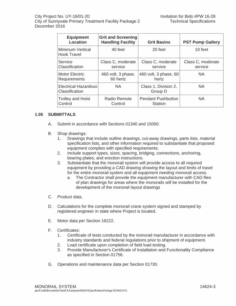
City Project No. UY-16/01-20 Invitation for Bids #PW 16-28City of Sunnyvale Primary Treatment Facility Package 2 Technical SpecificationsDecember 2016
MONORAIL SYSTEM 14624-3 pw://Carollo/Documents/Client/CA/Sunnyvale/9265A10/Specifications/Package 02/14624 (FS)
Equipment Location
Grit and Screening Handling Facility Grit Basins PST Pump Gallery
Minimum Vertical Hook Travel
40 feet 20 feet 10 feet
Service Classification
Class C, moderate service
Class C, moderate service
Class C, moderate service
Motor Electric Requirements
460 volt, 3 phase, 60 hertz
460 volt, 3 phase, 60 hertz
NA
Electrical Hazardous Classification
NA Class 1, Division 2, Group D
NA
Trolley and Hoist Control
Radio Remote Control
Pendant Pushbutton Station
NA
1.05 SUBMITTALS
A. Submit in accordance with Sections 01340 and 15050.
B. Shop drawings: 1. Drawings that include outline drawings, cut-away drawings, parts lists, material
specification lists, and other information required to substantiate that proposed equipment complies with specified requirements.
2. Include support types, sizes, spacing, bridging, connections, anchoring, bearing plates, and erection instructions.
3. Substantiate that the monorail system will provide access to all required equipment by providing a CAD drawing showing the layout and limits of travel for the entire monorail system and all equipment needing monorail access.a. The Contractor shall provide the equipment manufacturer with CAD files
of plan drawings for areas where the monorails will be installed for the development of the monorail layout drawings
C. Product data.
D. Calculations for the complete monorail crane system signed and stamped by registered engineer in state where Project is located.
E. Motor data per Section 16222.
F. Certificates:1. Certificate of tests conducted by the monorail manufacturer in accordance with
industry standards and federal regulations prior to shipment of equipment.2. Load certificate upon completion of field load testing.3. Provide Manufacturer's Certificate of Installation and Functionality Compliance
as specified in Section 01756.
G. Operations and maintenance data per Section 01730.

City Project No. UY-16/01-20 Invitation for Bids #PW 16-28City of Sunnyvale Primary Treatment Facility Package 2 Technical SpecificationsDecember 2016
MONORAIL SYSTEM 14624-4 pw://Carollo/Documents/Client/CA/Sunnyvale/9265A10/Specifications/Package 02/14624 (FS)
1.06 QUALITY ASSURANCE
A. Installer qualifications: Minimum 3 years' experience in, and regularly engaged in, field installation of monorail hoist systems.
B. Unload, store, and install monorail system under direct supervision of manufacturer.
1.07 DELIVERY, HANDLING, AND STORAGE
A. Assemble, paint, test, and adjust monorail system in manufacturer's shop before shipment as far as practical.
PART 2 PRODUCTS
2.01 MONORAIL
A. Manufacturers: One of the following or equal:1. CraneVeyor Corp. 2. Arrow CraneHoist Corp.
B. Maximum vertical deflection of monorail beam: Maximum span of monorail beam divided by 600.
C. Maximum lateral deflection of monorail beam: Maximum span of monorail beam divided by 360 when subjected to a lateral load of 20 percent of the lifted load.
D. Stops and bumpers: Adequate to absorb energy of and stop moving trolley at end of permitted travel.
E. Stools: Hard up connections with shims.
F. Length: As indicated in the Drawings.
G. Where indicated in the Drawings, provide additional bracing to extend the monorail beyond the limits of the support framing.
H. Labeling: Paint hoist capacity on monorail with minimum 4-inch high letters and numbers where clearly visible from operating floor.
I. Coating: Provide prime coat, intermediate coat, and finish coat as specified in Section 09960. The color of the finish coat shall be safety yellow. Provide coating applier with any special instructions for coating monorail surfaces that interface with the trolley hoist.
City Project No. UY-16/01-20 Invitation for Bids #PW 16-28City of Sunnyvale Primary Treatment Facility Package 2 Technical SpecificationsDecember 2016
MONORAIL SYSTEM 14624-5 pw://Carollo/Documents/Client/CA/Sunnyvale/9265A10/Specifications/Package 02/14624 (FS)
2.02 TROLLEY HOISTS
A. Manufacturers: One of the following or equal:1. Cleveland Tram Rail.2. P&H Hevi-Lift.3. Yale.
B. Type: Combination electric motor-driven trolleys and hoists, single-speed with trolley cushioned start, including mechanical brake, electrical brake, and upper hoist limit stop and load limiting device.
C. Hoisting speed: 15 feet per minute.
D. Distance from bottom of rail to inside of hook: Maximum 25 inches with hook in fully raised position.
E. Trolleys wheels: Single-flanged; forged steel, hardened to 425 Brinell; fitted with anti-friction bearings with lifetime seals; suitable for adjustment to monorails.
F. Safety lugs: Add safety lugs to manufacturer's standard design.
G. Drive units: Specially designed for monorail service with cushioned stop holding brakes.
H. Chain hoist.
I. Hoist drive speed reducer: With heat-treated steel helical gears; oil-lubricated with oiltight cases; shafts running in anti-friction bearings.
J. Limit switches and overload device: Manufacturer's standard.
K. Load chain: Specifically designed per HMI standards for chain hoists.
L. Hook: Safety type, able to rotate freely on bearing support with heavy-duty type safety latches.
M. Coating: Provide prime coat, intermediate coat, and finish coat in as specified in Section 09960. The color of the finish coat shall be safety yellow.
2.03 ELECTRIFICATION AND CONTROL
A. Electrification type: 4-bar electrification with Duct-O-Bar Figure 8.
B. Cable run: From junction box to cable reel, then to control unit.
C. Control unit: Pendant pushbutton station hanging from hoist to maximum 4 feetabove operation floor.
D. Control voltage: 120 volts alternating current, supplied from transformer on hoist.

City Project No. UY-16/01-20 Invitation for Bids #PW 16-28City of Sunnyvale Primary Treatment Facility Package 2 Technical SpecificationsDecember 2016
MONORAIL SYSTEM 14624-6 pw://Carollo/Documents/Client/CA/Sunnyvale/9265A10/Specifications/Package 02/14624 (FS)
E. Pushbuttons: 6-Button Pendant: 1. On.2. Off.3. Trolley Forward.4. Trolley Reverse.5. Hoist Up.6. Hoist Down.
F. Enclosures for control unit, electrical control, and reel: As scheduled and to meet the requirements as specified in Sections 17050 and 17710.
G. Control unit support: Steel cable.
H. Control accessories:1. Geared limit switch able to limit up and down travel with second switch
operated by hook to stop hoist when highest safe point is reached.2. Magnetic contactors for up and down operation and control.
I. Junction boxes: Suitable for connection of field services with ground pads.
PART 3 EXECUTION
3.01 INSTALLATION
A. Install monorail crane system in accordance with manufacturer's instructions.
3.02 MANUFACTURER'S FIELD SERVICES
A. Coordinate field service work with the manufacturer's representative, Owner, and Engineer prior to initiating such work.
B. Contractor shall furnish a qualified manufacturer's representative to provide manufacturer's field services as specified in Section 01756 and herein.
C. Installation assistance:1. Advise/observe the Contractor on the installation of the monorail system.2. Check and verify that installation of the monorail system is in accordance with
the Drawings and manufacturer's installation instructions.
3.03 COMMISSIONING AND PROCESS START-UP REQUIREMENTS
A. As specified in Section 01756 and this Section. Manufacturer Rep Onsite
Source Testing(Witnessed or
Non-witnessed)
Training Requirements
Installation Testing
FunctionalTesting
ProcessOperational
PeriodMaintenance
(hrs per session)
Operation (hrs per session) Trips
Days(each trip) Trips
Days(each trip) Trips
Days(each trip)
NA 2 2 1 1 NA NA NA

City Project No. UY-16/01-20 Invitation for Bids #PW 16-28City of Sunnyvale Primary Treatment Facility Package 2 Technical SpecificationsDecember 2016
MONORAIL SYSTEM 14624-7 pw://Carollo/Documents/Client/CA/Sunnyvale/9265A10/Specifications/Package 02/14624 (FS)
3.04 INSTALLATION/LOAD TESTING
A. Perform test in presence of manufacturer, Engineer, and Owner.
B. Test equipment with minimum load of 25 percent above rated capacity.
C. Provide load and slings for test:1. Remove when tests are completed.
D. Operate equipment through complete lift and lowering cycle and through complete travel of trolley to demonstrate quiet, smooth, and safe hoisting, braking, and traveling.
E. Correct defects.
3.05 USE OF MONORAIL CRANE SYSTEM
A. Prohibit hoisting equipment use until receipt of certificate with certified test weight.
B. Do not use monorail crane system for construction.
END OF SECTION

City Project No. UY-16/01-20 Invitation for Bids #PW 16-28City of Sunnyvale Primary Treatment Facility Package 2 Technical SpecificationsDecember 2016
JIB CRANES 14650-1 pw://Carollo/Documents/Client/CA/Sunnyvale/9265A10/Specifications/Package 02/14650 (FS)
SECTION 14650
JIB CRANES
PART 1 GENERAL
1.01 SUMMARY
A. Section includes: Jib cranes with trolley hoist, and footing and support.
B. Related sections:1. The Contract Documents are complementary; what is called for by one is as
binding as if called for by all.2. It is the Contractor's responsibility for scheduling and coordinating the Work of
subcontractors, suppliers, and other individuals or entities performing or furnishing any of Contractor's Work.
3. The following Sections are related to the Work described in this Section. This list of Related Sections is provided for convenience only and is not intended to excuse or otherwise diminish the duty of the Contractor to see that the completed Work complies accurately with the Contract Documents:a. Section 01612 - Seismic Design Criteria.b. Section 09960 - High-Performance Coatings.
1.02 REFERENCES
A. American Institute of Steel Construction (AISC):1. Manual of Steel Construction: Allowable Stress Design.
1.03 SYSTEM DESCRIPTION
A. Design requirements:1. All components and materials of construction shall be suitable for outdoor
installation. 2. Hoisting system: In accordance with ASME B30.11, ASME B30.16, and OSHA
standards.3. See Section 15050.4. Structural steel construction: In accordance with AISC Specifications.5. Working parts shall be arranged for convenient inspection, lubrication,
adjustment, repair, or replacement.
B. The jib crane and hoist system provided shall meet the following performance anddesign requirements:1. Jib crane and hoist load capacity: 2,000 pounds.2. Boom reach: 13 feet.3. Minimum clearance under boom: 15 feet.

City Project No. UY-16/01-20 Invitation for Bids #PW 16-28City of Sunnyvale Primary Treatment Facility Package 2 Technical SpecificationsDecember 2016
JIB CRANES 14650-2 pw://Carollo/Documents/Client/CA/Sunnyvale/9265A10/Specifications/Package 02/14650 (FS)
1.04 SUBMITTALS
A. Submit in accordance with Sections 01340 and 15050.
B. Product Data.
C. Shop drawings and calculations. 1. Drawings that include outline drawings, elevations, parts lists, material
specification lists, and other information required to substantiate that proposed equipment complies with specified requirements.
2. Include support types, sizes, spacing, connections, anchoring, bearing plates, and erection instructions.
3. Substantiate that the jib crane system will provide access to anticipated area for equipment removal by providing a CAD drawing showing the layout and limits of travel for the jib crane system and access area that the jib crane will cover. a. The Contractor shall provide the equipment manufacturer with CAD files
of plan drawings for area where the jib crane will be installed for the development of the area layout drawing that can be accessed by jib crane.
4. Footing structural design to support the jib crane.
D. Calculations for the complete jib crane system signed and stamped by registered engineer in state where Project is located.
E. Provide Manufacturer's Certificate of Installation and Functionality Compliance as specified in Section 01756.
F. Operations and maintenance data per Section 01730.
G. Certificates:1. Certificate of tests conducted by the jib crane manufacturer in accordance with
industry standards and federal regulations prior to shipment of equipment.2. Load certificate upon completion of field load testing.3. Provide Manufacturer's Certificate of Installation and Functionality Compliance
as specified in Section 01756.
1.05 QUALITY ASSURANCE
A. Installer qualifications: Minimum 3 years' experience in, and regularly engaged in, field installation of jib crane hoist systems.
B. Unload, store, and install jib crane system under direct supervision of manufacturer.
1.06 DELIVERY, HANDLING, AND STORAGE
A. Assemble, paint, test, and adjust jib crane system in manufacturer's shop before shipment as far as practical.

City Project No. UY-16/01-20 Invitation for Bids #PW 16-28City of Sunnyvale Primary Treatment Facility Package 2 Technical SpecificationsDecember 2016
JIB CRANES 14650-3 pw://Carollo/Documents/Client/CA/Sunnyvale/9265A10/Specifications/Package 02/14650 (FS)
PART 2 PRODUCTS
2.01 JIB CRANE
A. Design jib crane in accordance with AISC Specifications and Codes of the Manual of Steel Construction: Allowable Stress Design.
B. Design and installation of all systems shall meet CBC 2013 requirements.
C. The boom deflection shall be limited to allow safe and easy hoist travel.
D. The bottom roller assembly shall be adjustable for leveling the boom.
E. Provide limit stops on the boom to limit the travel of the trolley.
F. Provide a locking device to prevent boom swivel when desired.
G. Structural design calculations including footing pad, anchor bolt, wind load and seismic shall be signed by a California registered professional engineer.
H. Manufacturers: One of the following or equal:1. ACCO/Wright, Series 513.2. Bushman, Type 480-CBM.
2.02 TROLLEY HOIST
A. Provide low headroom manual trolley hoist on the jib crane.
B. The trolley hoist shall be an integrally built-geared trolley and hoist combination capable of operating on the jib crane boom.
C. Provide sufficient chain to allow a lift of 25 feet.
D. Manufacturers: One of the following or equal:1. Lift Tech.2. Yale and Towne, Division of Eaton, Inc.3. ACCO/Wright.
PART 3 EXECUTION
3.01 INSTALLATION
A. Adjust jib crane so that boom is level.
3.02 FIELD QUALITY CONTROL
A. Require manufacturer to inspect system before initial start-up and certify that system has been correctly installed and prepared for start-up as specified in this section and in Sections 15050 and 15958.

City Project No. UY-16/01-20 Invitation for Bids #PW 16-28City of Sunnyvale Primary Treatment Facility Package 2 Technical SpecificationsDecember 2016
JIB CRANES 14650-4 pw://Carollo/Documents/Client/CA/Sunnyvale/9265A10/Specifications/Package 02/14650 (FS)
B. Coordinate field service work with the manufacturer's representative, Owner, and Engineer prior to initiating such work.
C. Functional and operational testing: As specified in Section 01756.
D. Manufacturer's field services:1. Contractor shall furnish services of a qualified manufacturer's representative
experienced in installation and operation of equipment. 2. Contractor shall coordinate field service work with the manufacturer's
representative, Owner, and Engineer prior to initiating field service work.3. Manufacturer's representative shall perform the services described below and
specified in Section 01756.a. Installation assistance and inspection:
1) Advise/observe the Contractor on the installation. 2) Check and verify that installation is in accordance with the Drawings
and manufacturer's installation instructions.b. Field testing and verification of operation. c. Certification of Installation and Functionality Compliance: Comply with
Section 01756.4. Training of Owner's personnel:
a. One (1) trip for six (6) hours total. b. Operations: Two (2) sessions, each session for one (1) hour. c. Maintenance: Two (2) sessions, each session for two (2) hours.
END OF SECTION
City Project No. UY-16/01-20 Invitation for Bids #PW 16-28City of Sunnyvale Primary Treatment Facility Package 2 Technical SpecificationsDecember 2016
WINCHES 14670-1 pw://Carollo/Documents/Client/CA/Sunnyvale/9265A10/Specifications/Package 02/14670 (FS)
SECTION 14670
WINCHES
PART 1 GENERAL
1.01 SUMMARY
A. Section includes: winch system, including drum, wire rope, hook, motor, andelectrical controls. 1. Equipment Tag Numbers:
a. Grit Bin Winch - WNC-212.001.b. Screenings Bin Winch - WNC-212.002.
B. Related sections:1. The Contract Documents are complementary; what is called for by one is as
binding as if called for by all.2. It is the Contractor's responsibility for scheduling and coordinating the Work of
subcontractors, suppliers, and other individuals or entities performing or furnishing any of Contractor's Work.
3. The following Sections are related to the Work described in this Section. This list of Related Sections is provided for convenience only and is not intended to excuse or otherwise diminish the duty of the Contractor to see that the completed Work complies accurately with the Contract Documents.a. Section 01340 - Shop Drawings, Product Data and Samples. b. Section 01740 - Warranties and Bonds.c. Section 01756 - Commissioning and Process Start-Up.d. Section 01730 - Operation and Maintenance Data. e. Section 05190 - Mechanical Anchoring and Fastening to Concrete and
Masonry. f. Section 09960 - High-Performance Coatings.g. Section 15050 - Common Work Results for Mechanical Equipment. h. Section 16050 - Common Work Results for Electrical.i. Section 17710 - Control Systems - Panels, Enclosures, and Panel
Components.
1.02 REFERENCES
A. Occupational Safety and Health Administration (OSHA).
B. National Electrical Code (NEC):1. Article 610 - Cranes and Hoists.
C. National Electrical Manufacturer's Association (NEMA): 1. 250 – Enclosures for Electrical Equipment (1000 V Maximum).
City Project No. UY-16/01-20 Invitation for Bids #PW 16-28City of Sunnyvale Primary Treatment Facility Package 2 Technical SpecificationsDecember 2016
WINCHES 14670-2 pw://Carollo/Documents/Client/CA/Sunnyvale/9265A10/Specifications/Package 02/14670 (FS)
1.03 DEFINITIONS
A. NEMA 4X enclosure in accordance with NEMA 250.
1.04 SYSTEM DESCRIPTION
A. Provide winches as indicated on the Drawings and specified herein.1. Grit bin winch shall pull in a partially full 15- or 20-cubic yard bin weighing
22,000 lbs into required position.2. Screenings bin winch shall pull in an empty 15- or 20-cubic yard bin weighing
4,000 lbs into required position.
B. Submit calculations that substantiate that the proposed winch, drum, cable, and motor are sufficient sized for long-term successful operation. Assume that the design load is on four non-lubricated or non-bearing wheels on a flat concrete surface.
1.05 SUBMITTALS
A. Submit: As specified in Sections 01340 and 15050.
B. Product data: Provide component dimensions, configurations, construction details, joint details and attachments, utility and service requirements and locations.
C. Warranty as specified in Section 01740.
D. Bill of materials.
E. Manufacturer's installation instructions.
F. Operation and Maintenance Manual as specified in Section 01730.
G. Shop drawings:1. Indicate winch locations, large-scale plans, elevations, cross sections, rough-in
and anchor placement dimensions and tolerances, clearances required, and other information required for fabrication and installation.
2. Equipment sizing calculations.
H. Product data.
I. Spare Parts: 1. Spare parts: Not required.2. Provide complete spare parts list.
J. Seismic anchorage calculations.
City Project No. UY-16/01-20 Invitation for Bids #PW 16-28City of Sunnyvale Primary Treatment Facility Package 2 Technical SpecificationsDecember 2016
WINCHES 14670-3 pw://Carollo/Documents/Client/CA/Sunnyvale/9265A10/Specifications/Package 02/14670 (FS)
1.06 QUALITY ASSURANCE
A. Installer qualifications: Minimum 10 years of experience in, and regularly engaged in field installation of winches.
B. Assemble, paint, test, and adjust winches in manufacturer's shop before shipment.
1.07 DELIVERY, HANDLING, AND STORAGE
A. Unload, store, and install winches in accordance to manufacturer written instructions.
1.08 PROJECT CONDITIONS
A. Electrical area classification of installation location: Unclassified.
PART 2 PRODUCTS
2.01 WINCHES
A. Manufacturers: One of the following or equal:1. Thern, model as scheduled.
a. Inclusion of a specific manufacturer's name and model in the Specifications does not mean that the specific manufacturer's standard product will be acceptable. Specified manufacturer's or other manufacturer's standard product shall be modified as required to meet the Specifications
B. Type:1. Helical-worm gear power winch.2. Rated for pulling.
C. Automatic braking system.
D. TEFC UL listed severe duty brake motors with gear drive. 1. Minimum horsepower as scheduled.2. Power Feed: As scheduled.3. Equipped with a thermal overload protection activated on a time delay; and
with an electronic overload control that automatically shuts down the motor when the load movement is abruptly obstructed.
4. Total Gear Reduction: As scheduled.
E. Wire rope:1. Extra improved plow steel.2. Diameter: As scheduled. 3. Length: As scheduled.
F. Wire rope hook:1. Stainless steel construction.
City Project No. UY-16/01-20 Invitation for Bids #PW 16-28City of Sunnyvale Primary Treatment Facility Package 2 Technical SpecificationsDecember 2016
WINCHES 14670-4 pw://Carollo/Documents/Client/CA/Sunnyvale/9265A10/Specifications/Package 02/14670 (FS)
2. Swivel hook with safety latch.3. Hook opening dimension (minimum): Coordinate with the bin dimensions. The
bins are being furnished by others.
G. Drum:1. Grooved drum equipped with a rotary limit switch that stops the winch at
repeatable "home" position.2. Drum Diameter: As scheduled.3. Rotary limit switch: Field adjustable and mounted to outboard bearing end of
drum.4. Sufficient capacity to handle the scheduled diameter and length of wire rope.
H. Nameplates: Stainless steel nameplates giving the name of the manufacturer, model number, serial number, capacity, equipment tag number, and any other pertinent data shall be attached to each winch.
I. Frame: Heavy duty frame with mounting holes.
2.02 EQUIPMENT ANCHORAGE
A. Either the equipment manufacturer or Contractor shall prepare seismic anchorage calculations in accordance with Section 05190.
2.03 EQUIPMENT DIMENSIONS
A. Size critical equipment: Overall equipment dimensions shall not exceed the maximum allowable dimensions as indicated in the winch schedule.
2.04 ELECTRIFICATION AND CONTROL
A. As specified herein and indicated in the Drawings.
B. Rotary limit switch that allows locating the load into a preset "home" position.
C. Electronic overload control that automatically shuts the motor when the load movement is abruptly obstructed.
D. Remotely mounted pendant station.1. Two momentary contact pushbuttons in a NEMA 4X enclosure. Label
pushbuttons "Forward" and "Reverse".
2.05 FINISHES
A. As specified in Section 09960.
2.06 SOURCE TESTING
A. Perform load test at the factory.
City Project No. UY-16/01-20 Invitation for Bids #PW 16-28City of Sunnyvale Primary Treatment Facility Package 2 Technical SpecificationsDecember 2016
WINCHES 14670-5 pw://Carollo/Documents/Client/CA/Sunnyvale/9265A10/Specifications/Package 02/14670 (FS)
B. Test equipment with minimum load of 25 percent above rated capacity.
C. Correct defects.
PART 3 EXECUTION
3.01 INSTALLATION
A. Install winch system in accordance with manufacturer's instructions and in accordance with Section 15050.
B. Coordinate installation such that the center line of the winch drum is level with the hook up point of the bin that the winch is intended to serve. Comply the manufacturer's specified tolerance for each size.
C. Require manufacturer to inspect system before initial start-up and certify that system has been correctly installed and prepared for start-up as specified in this section and in Sections 15050 and 15958.
D. Coordinate field service work with the manufacturer's representative, Owner, and Engineer prior to initiating such work.
E. Functional and operational testing: As specified in Section 01756.
3.02 FIELD QUALITY CONTROL
A. Manufacturer's field services:1. Contractor shall furnish services of a qualified manufacturer's representative
experienced in installation and operation of winches. 2. Contractor shall coordinate field service work with the manufacturer's
representative, Owner, and Engineer prior to initiating field service work.3. Manufacturer's representative shall perform the services described below and
specified in Section 01756.a. Installation assistance and inspection:
1) Advise/observe the Contractor on the installation. 2) Check and verify that installation is in accordance with the Drawings
and manufacturer's installation instructions.b. Field testing and verification of operation. c. Certification of Installation and Functionality Compliance: Comply with
Section 01756.d. Training of Owner's personnel.
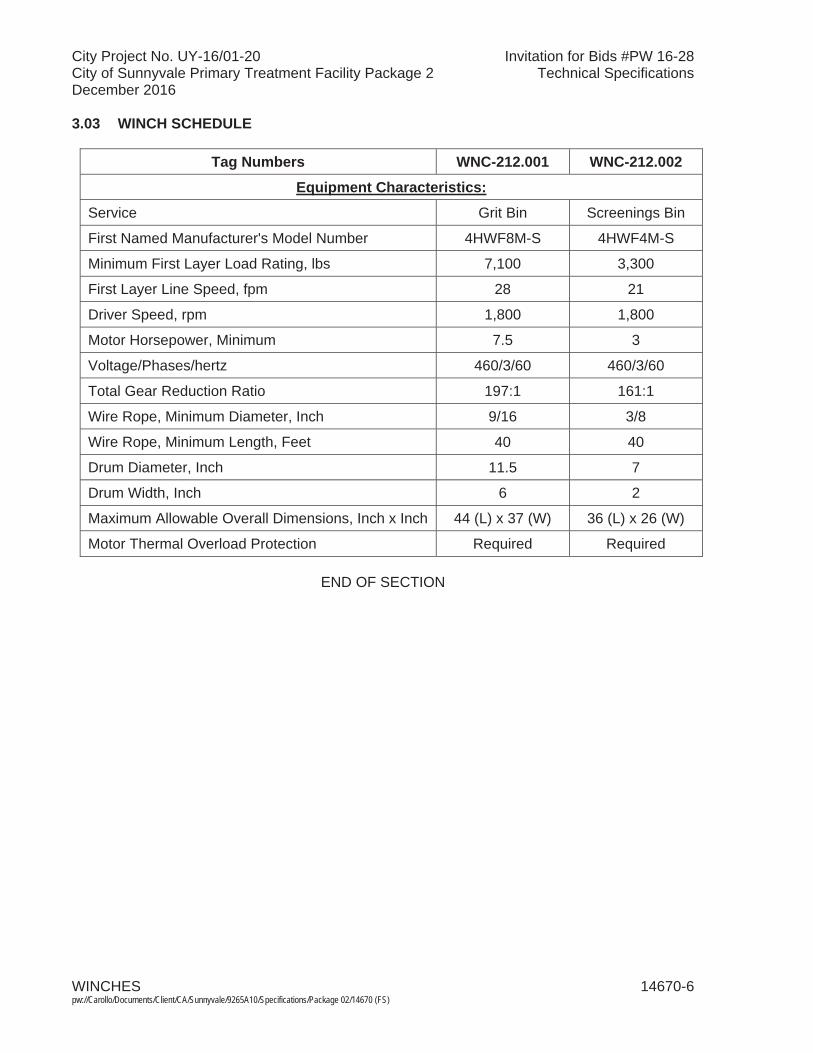
City Project No. UY-16/01-20 Invitation for Bids #PW 16-28City of Sunnyvale Primary Treatment Facility Package 2 Technical SpecificationsDecember 2016
WINCHES 14670-6 pw://Carollo/Documents/Client/CA/Sunnyvale/9265A10/Specifications/Package 02/14670 (FS)
3.03 WINCH SCHEDULE
Tag Numbers WNC-212.001 WNC-212.002
Equipment Characteristics:
Service Grit Bin Screenings Bin
First Named Manufacturer's Model Number 4HWF8M-S 4HWF4M-S
Minimum First Layer Load Rating, lbs 7,100 3,300
First Layer Line Speed, fpm 28 21
Driver Speed, rpm 1,800 1,800
Motor Horsepower, Minimum 7.5 3
Voltage/Phases/hertz 460/3/60 460/3/60
Total Gear Reduction Ratio 197:1 161:1
Wire Rope, Minimum Diameter, Inch 9/16 3/8
Wire Rope, Minimum Length, Feet 40 40
Drum Diameter, Inch 11.5 7
Drum Width, Inch 6 2
Maximum Allowable Overall Dimensions, Inch x Inch 44 (L) x 37 (W) 36 (L) x 26 (W)
Motor Thermal Overload Protection Required Required
END OF SECTION
City Project No. UY-16/01-20 Invitation for Bids #PW 16-28City of Sunnyvale Primary Treatment Facility Package 2 Technical SpecificationsDecember 2016
COMMON WORK RESULTS FOR MECHANICAL EQUIPMENT 15050-1 pw://Carollo/Documents/Client/CA/Sunnyvale/9265A10/Specifications/Package 02/15050 (FS)
SECTION 15050
COMMON WORK RESULTS FOR MECHANICAL EQUIPMENT
PART 1 GENERAL
1.01 SUMMARY
A. Section includes: Basic design and performance requirements for mechanical equipment.
B. Related sections:1. The Contract Documents are complementary; what is called for by one is as
binding as if called for by all.2. It is the Contractor's responsibility for scheduling and coordinating the Work of
subcontractors, suppliers, and other individuals or entities performing or furnishing any of Contractor's Work.
3. The following Sections are related to the Work described in this Section. This list of Related Sections is provided for convenience only and is not intended to excuse or otherwise diminish the duty of the Contractor to see that the completed Work complies accurately with the Contract Documents:a. Section 01340 - Shop Drawings, Product Data and Samples. b. Section 01560 - Temporary Controls.c. Section 01605 - Product Requirements.d. Section 01610 - Project Design Criteria. e. Section 01612 - Seismic Design Criteria.f. Section 01756 - Commissioning and Process Start-up.g. Section 01730 - Operating and Maintenance Data.h. Section 03600 - Grouting. i. Section 05190 - Mechanical Anchoring and Fastening to Concrete and
Masonry.j. Section 05120 - Structural Steel.k. Section 09960 - High-Performance Coatings.l. Section 10400 - Signage.m. Section 15052 - Common Work Results for General Piping.n. Section 15082 - Piping Insulation.o. Section 15958 - Mechanical Equipment Testing.p. Section 16950 - Field Electrical Acceptance Tests.q. Section 17950 - Testing Calibration and Commissioning.
1.02 REFERENCES
A. American Gear Manufacturer's Association (AGMA) Standards:1. 6001-E08 – Design and Selection of Components for Enclosed Gear Drives.
B. American Bearing Manufactures Association (ABMA) Standards:1. 9 - Load Ratings and Fatigue Life for Ball Bearings.2. 11 - Load Ratings and Fatigue Life for Roller Bearings.
City Project No. UY-16/01-20 Invitation for Bids #PW 16-28City of Sunnyvale Primary Treatment Facility Package 2 Technical SpecificationsDecember 2016
COMMON WORK RESULTS FOR MECHANICAL EQUIPMENT 15050-2 pw://Carollo/Documents/Client/CA/Sunnyvale/9265A10/Specifications/Package 02/15050 (FS)
C. American Petroleum Institute (API):1. 682 - Shaft Sealing Systems for Centrifugal and Rotary Pumps.
D. ASTM International (ASTM):1. A 36 - Standard Specification for Carbon Structural Steel.2. A 48 - Standard Specification for Gray Iron Castings.3. A 125 - Standard Specification for Steel Springs, Helical, Heat-Treated.4. A 153 - Standard Specification for Zinc Coating (Hot-Dip) on Iron and Steel
Hardware.5. A 193 - Standard Specification for Alloy-Steel and Stainless Steel Bolting for
High Temperature or High Pressure Service and Other Special Purpose Applications.
6. A 194 - Standard Specification for Carbon and Alloy Steel Nuts for Bolts for High Pressure or High Temperature Service, or Both.
7. A 320 - Standard Specification for Alloy-Steel and Stainless Steel Bolting for Low-Temperature Service.
8. A 536 - Standard Specification for Ductile Iron Castings.9. A 653 - Standard Specification for Steel Sheet, Zinc-Coated (Galvanized) or
Zinc-Iron Alloy-Coated (Galvannealed) by the Hot-Dip Process.10. B 61 - Standard Specification for Steam or Valve Bronze Castings.11. B 62 - Standard specification for Composition Bronze or Ounce Metal
Castings.12. B 505 - Standard Specification for Copper Alloy Continuous Castings.13. B 584 - Standard Specification for Copper Alloy Sand Castings for General
Applications.14. F 593 - Standard Specification for Stainless Steel Bolts, Hex Cap Screws, and
Studs.15. F 594 - Standard Specification for Stainless Steel Nuts.16. F 2329 - Standard Specification for Zinc Coating, Hot-Dip, Requirements for
Application to Carbon and Alloy Steel Bolts, Screws, Washers, Nuts, and Special Threaded Fasteners.
E. Food and Drug Administration (FDA).
F. International Concrete Repair Institute (ICRI):1. 310.2R - Selecting a specifying Concrete surface preparation for Sealers,
Coatings, Polymer Overlays, and Concrete Repair.
G. Hydraulic Institute (HI).
H. NSF International (NSF).
1.03 DEFINITIONS
A. Special tools: Tools that have been specifically made for use on unit of equipment for assembly, disassembly, repair, or maintenance.
B. Resonant frequency: That frequency at which a small driving force produces an ever-larger vibration if no dampening exists.
City Project No. UY-16/01-20 Invitation for Bids #PW 16-28City of Sunnyvale Primary Treatment Facility Package 2 Technical SpecificationsDecember 2016
COMMON WORK RESULTS FOR MECHANICAL EQUIPMENT 15050-3 pw://Carollo/Documents/Client/CA/Sunnyvale/9265A10/Specifications/Package 02/15050 (FS)
C. Rotational frequency: The revolutions per unit of time usually expressed as revolutions per minute.
D. Critical frequency: Same as resonant frequency for the rotating elements or the installed machine and base.
E. Peak vibration velocity: The root mean square average of the peak velocity of the vibrational movement times the square root of 2 in inches per second.
F. Rotational speed: Same as rotational frequency.
G. Maximum excitation frequency: The excitation frequency with the highest vibration velocity of several excitation frequencies that are a function of the design of a particular machine.
H. Critical speed: Same as critical frequency.
I. Free field noise level: Noise measured without any reflective surfaces (an idealized situation); sound pressure levels at 3 feet from the source unless specified otherwise.
J. Operating weight: The weight of unit plus weight of fluids or solids normally contained in unit during operation.
1.04 SYSTEM DESCRIPTION
A. General:1. Product requirements as specified in Section 01340. 2. Materials in contact with drinking water as specified here-in.3. Provisions specified under each technical equipment specification prevail over
and supersede conflicting provisions as specified in this Section.4. Provide equipment and parts that are suitable for stresses, which may occur
during fabrication, transportation, erection, and operation.5. Provide equipment that has not been in service prior to delivery, except as
required by tests.6. Like parts of duplicate units are to be interchangeable.7. When 2 or more units of equipment for the same purpose are required, provide
products of same manufacturer.8. Equipment manufacturer's responsibility extends to selection and mounting of
gear drive units, motors or other prime movers, accessories, and auxiliaries required for proper operation.
9. When necessary, modify manufacturer's standard product to conform to specified requirements or requirements indicated on the Drawings andcontained in Laws and Regulations.
B. Material requirements:1. Materials: Suitable for superior corrosion resistance and for services under
conditions normally encountered in similar installations.2. Dissimilar metals: Separate contacting surfaces with dielectric material.
City Project No. UY-16/01-20 Invitation for Bids #PW 16-28City of Sunnyvale Primary Treatment Facility Package 2 Technical SpecificationsDecember 2016
COMMON WORK RESULTS FOR MECHANICAL EQUIPMENT 15050-4 pw://Carollo/Documents/Client/CA/Sunnyvale/9265A10/Specifications/Package 02/15050 (FS)
C. Power transmission systems:1. Power transmission equipment: V-belts, sheaves, shaft couplings, chains,
sprockets, mechanical variable-speed drives, variable frequency drives, gear reducers, open and enclosed gearing, clutches, brakes, intermediate shafting, intermediate bearings, and U-joints are to be rated for 24 hour-a-day continuous service or frequent stops-and-starts intermittent service, whichever is most severe, and sized with a minimum service factor of 1.5:a. Apply 1.5 service factor to nameplate horsepower and torque of prime
source of power and not to actual equipment loading.b. Apply service factors higher than 1.5 when recommended for continuous
24 hour per day operation and shock loadings in accordance withAGMA 6001-E08, other applicable AGMA standards, or other applicablereferenced standards.
c. When manufacturer recommends service factor greater than 1.5,manufacturer's recommendation takes precedence.
D. Vibration:1. Resonant frequency:
a. For single speed equipment, ensure there are no natural resonant frequencies within 25 percent above or below the operating rotational frequencies or multiples of the operating rotational frequencies that may be excited by the equipment design.
b. For variable speed equipment, ensure there are no natural resonant frequencies within 25 percent above or below the range of operating frequencies.
2. Design, balance, and align equipment to meet the vibration criteria specified in Section 15958.
E. Equipment mounting and anchoring:1. Mount equipment on cast iron or welded steel bases with structural steel
support frames.a. Utilize continuous welds to seal seams and contact edges between steel
members.b. Grind welds smooth.
2. Provide bases and supports with machined support pads, dowels for alignment of mating of adjacent items, adequate openings to facilitate grouting, and openings for electrical conduits.
3. Provide jacking screws in bases and supports for equipment weighing over 1,000 pounds.
4. Design equipment anchorage, supports, and connections for dead load, running loads, loads during start-up, seismic load specified in Section 01612, and other loads as required for proper operation of equipment.
5. Anchorage of equipment to concrete or masonry: a. Perform calculations and determine number, size, type, strength, and
location of anchor bolts or other connections.b. Unless otherwise indicated on the Drawings, select and provide anchors
from the types specified in Section 05190. c. Provide bolt sleeves around cast-in anchor bolts for heavy equipment:
1) Adjust bolts to final location and fill sleeve with non-shrink grout.
City Project No. UY-16/01-20 Invitation for Bids #PW 16-28City of Sunnyvale Primary Treatment Facility Package 2 Technical SpecificationsDecember 2016
COMMON WORK RESULTS FOR MECHANICAL EQUIPMENT 15050-5 pw://Carollo/Documents/Client/CA/Sunnyvale/9265A10/Specifications/Package 02/15050 (FS)
6. Anchorage of equipment to metal supports: Perform calculations and determine number, size, type, strength, and location of bolts used to connect equipment to metal supports.
7. Unless otherwise indicated on the Drawings, install equipment supported on concrete over non-shrink grout pads as specified in this Section.
F. Seismic design:1. Design equipment anchorage and related details for seismic design criteria as
specified in Section 01612. 2. For equipment with operating weight of 400 pounds and greater that is
supported 4 feet or less above the floor and all equipment that is supported higher than 4 feet above the floor, provide calculations for:a. The operating weight and location of the centroid of mass for the
equipment.b. Forces and overturning moments.c. Shear and tension forces in equipment anchorages, supports, and
connections.d. The design of equipment anchorage, supports, and connections based on
calculated shear and tension forces.
G. Equipment units weighing 50 pounds or more: Provide with lifting lugs or eyes to allow removal with hoist or other lifting device.
1.05 SUBMITTALS
A. Product data:1. For each item of equipment:
a. Design features.b. Load capacities.c. Efficiency ratings.d. Material designations by UNS alloy number or ASTM Specification and
Grade.e. Data needed to verify compliance with the Specifications.f. Catalog data.g. Name plate data.h. Clearly mark submittal information to show specific items, materials, and
accessories or options being furnished.2. Gear reduction units:
a. Engineering information in accordance with applicable AGMA standards.b. Gear mesh frequencies.
B. Shop drawings:1. Drawings for equipment:
a. Drawings that include outline drawings, cut-away drawings, parts lists, material specification lists, and other information required to substantiate that proposed equipment complies with specified requirements.
2. Outline drawings showing equipment, driver, driven equipment, pumps, seal, motor(s) or other specified drivers, variable frequency drive, shafting, U-joints, couplings, drive arrangement, gears, base plate or support dimensions, anchor bolt sizes and locations, bearings, and other furnished components.

City Project No. UY-16/01-20 Invitation for Bids #PW 16-28City of Sunnyvale Primary Treatment Facility Package 2 Technical SpecificationsDecember 2016
COMMON WORK RESULTS FOR MECHANICAL EQUIPMENT 15050-6 pw://Carollo/Documents/Client/CA/Sunnyvale/9265A10/Specifications/Package 02/15050 (FS)
3. Installation instructions including leveling and alignment tolerances, grouting, lubrication requirements, and initial Installation Testing procedures.
4. Wiring, control schematics, control logic diagrams and ladder logic or similar for computer based controls.
5. Recommended or normal operating parameters such as temperatures and pressures.
6. Alarm and shutdown set points for all controls furnished.
C. Calculations:1. Calculations and other information to substantiate equipment base plates,
supports, bolts, anchor bolts, and other connections meet minimum design strength requirements and seismic design criteria specified in Section 01612.
2. ABMA 9 or ABMA 11 L10 life for bearings calculation methods for drivers, pumps, gears, shafts, motors, and other driveline components with bearings.
3. Calculations and other information to substantiate that operating rotational frequencies meet the requirements of this Section.
4. Torsional analysis of power transmission systems: When torsional analysis specified in the equipment sections, provide: a. Sketch of system components identifying physical characteristics
including mass, diameter, thickness, and stiffness.b. Results of analysis including first and second critical frequencies of
system components and complete system.5. Calculations shall be signed and stamped by a civil or structural engineer
registered to practice in the state where the Project is located.6. For products subjected to lead limits submit one of the following:
a. Calculations of the weighted average of lead content in each component that comes in contact with water conforming to the maximum lead limits in the Reduction of Lead in Drinking Water Act.
b. Certification by an independent ANSI accredited third party, including, but not limited to, NSF International, as being lead free.
D. Quality control submittals:1. Source quality control reports and certified test data as specified in
Section 15958. 2. Submit factory test reports before shipment.3. Certified static and dynamic balancing reports for rotating equipment.4. Field quality control reports and test data as specified in Section 15958. 5. Submit material test reports as specified in the equipment sections.
E. Operation and maintenance manuals:1. As specified in Section 01730. 2. Submit prior to training of Owner's personnel.3. Make available at project site complete copy of manuals for use by field
personnel and Engineer during commissioning and process start-up of equipment.
4. Include manufacturer and model number of every bearing; include calculated ball pass frequencies of installed equipment for both inner and outer raceways.
5. Include motor rotor bar pass frequencies.
F. Commissioning and process start-up submittals: As specified in Section 01756.
City Project No. UY-16/01-20 Invitation for Bids #PW 16-28City of Sunnyvale Primary Treatment Facility Package 2 Technical SpecificationsDecember 2016
COMMON WORK RESULTS FOR MECHANICAL EQUIPMENT 15050-7 pw://Carollo/Documents/Client/CA/Sunnyvale/9265A10/Specifications/Package 02/15050 (FS)
1.06 QUALITY ASSURANCE
A. Manufacturer's field service:1. Furnish services of authorized representative specially trained in installation of
equipment:a. Visit project site and perform tasks necessary to certify installation as
specified in Section 01756.
1.07 DELIVERY, STORAGE, AND HANDLING
A. Refer to Section 01605 for additional requirements.
B. Packing and shipping:1. Equipment: Pack in boxes, crates, or otherwise protect from damage and
moisture, dust, or dirt during shipment, handling, and storage.2. Bearings: Separately pack or otherwise suitably protect during transport.3. Spare parts: Deliver in boxes labeled with contents, equipment to which spare
parts belong, and name of Contractor.
C. Storage:1. Equipment having bearings:
a. Store in enclosed facilities.b. Rotate units at least once per month or more often as recommended by
the manufacturer to protect rotating elements and bearings.2. Gear boxes: Oil filled or sprayed with rust preventive protective coating.
D. Protection:1. Equipment: Protect equipment from deleterious exposure.2. Painted surfaces: Protect against impact, abrasion, discoloration, and other
damage.
1.08 SEQUENCING AND SCHEDULING
A. Equipment anchoring: Obtain anchoring material and templates or setting drawings from equipment manufacturers in adequate time for anchors to be cast-in-place when concrete is placed.
B. Coordinate details of equipment with other related parts of the Work, including verification that structures, piping, wiring, and equipment components are compatible.
C. Commissioning and process start-up submittals: As specified in Section 01756: 1. Perform general commissioning and process start-up and testing procedures
after operation and maintenance manuals for equipment have been receivedand accepted.
2. Conduct functional testing of mechanical or electrical systems when each system is substantially complete and after general Installation testing procedures have been successfully completed.
3. Functional testing requirements as specified in Sections 01756, 15958, 16950, and 17950 and the equipment sections.

City Project No. UY-16/01-20 Invitation for Bids #PW 16-28City of Sunnyvale Primary Treatment Facility Package 2 Technical SpecificationsDecember 2016
COMMON WORK RESULTS FOR MECHANICAL EQUIPMENT 15050-8 pw://Carollo/Documents/Client/CA/Sunnyvale/9265A10/Specifications/Package 02/15050 (FS)
1.09 MAINTENANCE
A. Special tools:1. When specified, provide special tools required for operation and maintenance.2. Mark or tag and list such tools in maintenance and operations instructions.
Describe use of each tool.
B. Spare belts:1. When spare belts are specified, furnish 1 spare belt for every different type
and size of belt-driven unit:a. Where 2 or more belts are involved, furnish matched sets.b. Identify as to equipment, design, horsepower, speed, length, sheave size,
and use.c. Package in boxes labeled with identification of contents.
C. Spare parts:1. Assume responsibility until turned over to Owner. 2. Store in enclosed facilities.3. Furnish itemized list and match identification tag attached to every part.4. List parts by generic title and identification number.5. Furnish name, address, and telephone number of supplier and spare parts
warehouse.
PART 2 PRODUCTS
2.01 MATERIALS
A. Lead Limits1. Materials in contact with drinking water: In accordance with California Health
and Safety Code, Section 116875.
B. Ferrous materials:1. Steel for members used in fabrication of assemblies: ASTM A 36.2. Iron castings: ASTM A 48, tough, close-grained gray iron, free from blowholes,
flaws, and other imperfections.3. Ductile iron castings: ASTM A 536, Grade 65-45-12, free from flaws and
imperfections.4. Galvanized steel sheet: ASTM A 653, minimum 0.0635 inch (16 gauge).5. Expanded metal: ASTM A 36, 13 gauge, 1/2-inch flat pattern expanded metal.
C. Nonferrous materials:1. Stainless steel: Type 304 or 316 as specified. Provide L grade where welding
required.2. Bronze in contact with wastewater: Composition of not more than 2 percent
aluminum nor more than 6 percent zinc; UNS Alloy C83600, C89833, C89520, C92200, or C93700 in accordance with ASTM B 61, B 62, B 505, or B 584, when not specified otherwise.

City Project No. UY-16/01-20 Invitation for Bids #PW 16-28City of Sunnyvale Primary Treatment Facility Package 2 Technical SpecificationsDecember 2016
COMMON WORK RESULTS FOR MECHANICAL EQUIPMENT 15050-9 pw://Carollo/Documents/Client/CA/Sunnyvale/9265A10/Specifications/Package 02/15050 (FS)
D. Dielectric materials for separation of dissimilar metals:1. Neoprene, bituminous impregnated felt, heavy bituminous coatings,
nonmetallic separators or washers, or other materials.
E. Non-shrink grout: As specified in Section 03600.
2.02 FASTENERS
A. General:1. Material: As specified in the individual specifications.2. Where fasteners are specified to be galvanized, shall be galvanized in
accordance with ASTM A 153 or ASTM F 2329.
B. Mechanical anchors:1. As specified in Section 01612 and Section 05190.
C. High-strength fasteners:1. As specified in Section 05120.
D. Flange bolts: 1. As specified in Section 15082.
E. Mechanical assembly fasteners: 1. Stainless steel:
a. High Temperature Service or High Pressure Service:1) Bolts: ASTM A 193, Grade B8 (304 SST) or Grade B8M (316 SST),
Class 1, heavy hex.2) Nuts: ASTM A 194, Grade 8, heavy hex.3) Washers: Alloy group matching bolts and nuts.
b. Low Temperature Service: 1) Bolts: ASTM A 320, Grade B8 (304 SST) or Grade B8M (316 SST),
Class 1, heavy hex. 2) Nuts: ASTM A 194, Grade 8 (304 SST) or Grade B8M (316 SST),
heavy hex.3) Washers: Alloy group matching bolts and nuts.
c. General service:1) Bolts: ASTM F 593, Alloy group 1 (304 SST) or Alloy group 2 (316
SST). 2) Nuts: ASTM F 594, Alloy group 1 (304 SST) or Alloy group 2 (316
SST). 3) Washers: Alloy group matching bolts and nuts.
2. Carbon Steel.
2.03 SHAFT COUPLINGS
A. General:1. Type and ratings: Provide non-lubricated type, designed for not less than
100,000 hours of operating life.2. Sizes: Provide as recommended by manufacturer for specific application,
considering horsepower, speed of rotation, and type of service.

City Project No. UY-16/01-20 Invitation for Bids #PW 16-28City of Sunnyvale Primary Treatment Facility Package 2 Technical SpecificationsDecember 2016
COMMON WORK RESULTS FOR MECHANICAL EQUIPMENT 15050-10pw://Carollo/Documents/Client/CA/Sunnyvale/9265A10/Specifications/Package 02/15050 (FS)
3. Use: Use of couplings specified in this Section does not relieve Contractor ofresponsibility to provide precision alignment of driver-driven units as required by equipment manufacturer and alignment criteria specified elsewhere in this Section.
4. Flexible coupling elements shall be replaceable without motor removal.
B. Shaft couplings - close coupled: Shaft couplings for close coupled electric motor driven equipment 1/2 horsepower or larger and subject to sudden torque reversals or shock loading:1. Manufacturers: One of the following or equal:
a. T.B. Woods, Dura-Flex, L-Jaw C-Jaw or G-Jaw.b. Lovejoy, S-Flex.c. Rexnord - Omega.
2. Provide flexible couplings designed to accommodate angular misalignment, parallel misalignment, and end float.
3. Manufacture flexible component of coupling from synthetic rubber, or urethane.
4. Provide service factor of 2.5 for electric motor drives and 3.5 for engine drives.5. Do not allow metal-to-metal contact between driver and driven equipment.6. Examples of loads where sudden torque reversals may be expected:
a. Reciprocating pumps, blowers, and compressors.b. Conveyor belts.c. Reversing equipment.
C. Shaft couplings - direct connected: Shaft couplings for direct connected electric motor driven equipment 1/2 horsepower or larger and subject to normal torque, non-reversing applications:1. Manufacturers: One of the following or equal:
a. Rexnord - Falk.b. T.B. Woods, Dura-Flex, Sure-Flex or Form-Flex.
2. Provide flexible couplings designed to accommodate shock loading, vibration, and shaft misalignment or offset.
3. Provide flexible connecting element of rubber and reinforcement fibers.4. Connect stub shafts through collars or round flanges, firmly keyed to their
shafts with neoprene cylinders held to individual flanges by through pins.
D. Spacer couplings: Where cartridge type mechanical seals or non-split seals are specified, provide a spacer type coupling of sufficient length to remove the seal without disturbing the driver or driven equipment unless noted otherwise in the individual equipment specifications.
E. Specialized couplings: Where requirements of equipment dictate specialized features, supply coupling recommended for service by manufacturer.
2.04 STUFFING BOX, SEAL CHAMBER, AND SHAFT SEALS
A. General:1. Unless otherwise noted in the equipment section, provide cartridge type,
double mechanical shaft seals for pumps.2. Provide a stuffing box large enough for a double mechanical seal.
City Project No. UY-16/01-20 Invitation for Bids #PW 16-28City of Sunnyvale Primary Treatment Facility Package 2 Technical SpecificationsDecember 2016
COMMON WORK RESULTS FOR MECHANICAL EQUIPMENT 15050-11pw://Carollo/Documents/Client/CA/Sunnyvale/9265A10/Specifications/Package 02/15050 (FS)
3. Where packing is specified, provide stuffing box large enough to receive a double mechanical seal.
4. Provide seal or packing flush connections, (3/4-inch size unless another size is indicated on the Drawings).
5. Provide and route leakage drain line to nearest equipment floor drain indicated on the Drawings.
6. For pumps with packing, design packing gland to allow adjustment and repacking without dismantling pump except to open up packing box.
7. Seal or packing flush requirements shall be in accordance with API Standard 682 requirements. Unless otherwise indicated, specified or required by the equipment and seal manufacturers, the following API flushing Plan arrangements shall be utilized as appropriate for the application:a. Single seal, clean water applications: Plan 11 (Discharge bypass to seal).b. Single seal, vertical pump applications: Plan 13 (Seal bypass to suction).c. Single seal, clean hot water (greater than 180 degrees Fahrenheit)
applications: Plan 23 (Seal cooler and pumping ring).d. Single seal, solids, or contaminants containing water applications: Plan 32
(External seal water- see Carollo typical detail # M262).e. Double seal applications: Plan 54 (External seal water- see Carollo typical
detail # M262).
B. Packing: When specified in the equipment section of the specifications, provide the following type of packing:1. Wastewater, water, and sludge applications:
a. Asbestos free.b. PTFE (Teflon) free.c. Braided graphite.d. Manufacturers: One of the following or equal:
1) Chesterton, 1400.2) John Crane Inc., equivalent product.
2. Drinking water service:a. Approved by the FDA. b. As specified in Section 01600. c. Asbestos free.d. Material: Braided PTFE (Teflon).e. Manufacturers: One of the following or equal:
1) Chesterton, 1725.2) John Crane, Inc., equivalent product.
C. Mechanical seals: Provide seal types specified in the equipment sections and as specified.1. Provide seal types meeting the following requirements:
a. Balanced hydraulically.b. Spring: Stationary, out of pumping fluid, Hastelloy C for split seals.c. O-ring: Viton 747.d. Gland: Type 316L stainless steel.e. Set screws: Type 316L stainless steel.f. Faces: Reaction bonded, Silicon Carbide.

City Project No. UY-16/01-20 Invitation for Bids #PW 16-28City of Sunnyvale Primary Treatment Facility Package 2 Technical SpecificationsDecember 2016
COMMON WORK RESULTS FOR MECHANICAL EQUIPMENT 15050-12pw://Carollo/Documents/Client/CA/Sunnyvale/9265A10/Specifications/Package 02/15050 (FS)
g. Seal designed to withstand 300 pounds per square inch gauge minimum differential pressures in either direction; no requirement for seal buffer pressure to be maintained when pump is not operational even though process suction head may be present in pump.
2. Cartridge type single mechanical: Manufacturers: One of the following or equal:a. Chesterton, S10.b. John Crane, 5610 Series.
3. Cartridge type double mechanical: Manufacturers: One of the following or equal:a. Chesterton, S20.b. John Crane, 5620 Series.
4. Split face single mechanical: Manufacturers: One of the following or equal:a. Chesterton, 442C. b. John Crane, 3740.
2.05 GEAR REDUCTION UNITS
A. Type: Helical or herringbone, unless otherwise specified.
B. Design:1. Made of alloys treated for hardness and for severe service.2. AGMA Class II service:
a. Use more severe service condition when such is recommended by unit'smanufacturer.
3. Cast iron housing with gears running in oil.4. Anti-friction bearings.5. Thermal horsepower rating based on maximum horsepower rating of prime
mover not actual load.6. Manufactured in accordance with applicable AGMA standards.
C. Planetary gear units are not to be used.
2.06 BELT DRIVES
A. Sheaves:1. Separately mounted on bushings by means of at least 3 pull-up bolts or cap
tightening screws.2. When 2 sheave sizes are specified, provide separate belts sized for each set
of sheaves.3. Statically balanced for all; dynamically balanced for sheaves that operate at
peripheral speed of more than 5,500 feet per minute.4. Key bushings to drive shaft.
B. Belts: Anti-static type when explosion-proof equipment or environment is specified.
City Project No. UY-16/01-20 Invitation for Bids #PW 16-28City of Sunnyvale Primary Treatment Facility Package 2 Technical SpecificationsDecember 2016
COMMON WORK RESULTS FOR MECHANICAL EQUIPMENT 15050-13pw://Carollo/Documents/Client/CA/Sunnyvale/9265A10/Specifications/Package 02/15050 (FS)
C. Manufacturers: One of the following or equal:1. Dodge, Dyna-V belts with matching Dyna-V sheaves and Taper-Lock
bushings.2. T.B. Wood's, Ultra-V belts with matching Sure-Grip sheaves and Sure-Grip
bushings.
2.07 BEARINGS
A. Type: Oil or grease lubricated, ball or roller antifriction type, of standard manufacture.
B. Oil lubricated bearings: Provide either pressure lubricating system or separate oil reservoir splash type system:1. Size oil lubrication systems to safely absorb heat energy generated in bearings
when equipment is operating under normal conditions and with the temperature 15 degree Fahrenheit above the maximum design temperature as specified in Section 01610.
2. Provide an external oil cooler when required to satisfy the specified operating conditions:a. Provide air cooled system if a water-cooling source is not indicated on the
Drawings. b. Equip oil cooler with a filler pipe and external level gauge.
C. Grease lubricated bearings, except those specified to be factory sealed: Fit with easily accessible grease supply, flush, drain, and relief fittings:1. Lubrication lines and fittings:
a. Lines: Minimum 1/4-inch diameter stainless steel tubing.b. Multiple fitting assemblies: Mount fittings together in easily accessible
location.c. Use standard hydraulic type grease supply fittings:
1) Manufacturers: One of the following or equal:a) Alenite.b) Zerk.
D. Ratings: Rated in accordance with ABMA 9 or ABMA 11 L10 life for bearings rating life of not less than 50,000 hours:1. Higher ratings, when specified in other Sections, supersede preceding
requirement.
2.08 SAFETY GUARDS
A. Drive assemblies: Enclose sprockets, belts, drive chains, gearings, couplings, and other moving parts on drive assemblies in safety enclosures that are in compliance with applicable Laws and Regulations, including but not limited to Cal OSHA.
B. Shafts: Provide guards that protect personnel from rotating shafts or components within 7.5 feet of floors or operating platforms.
City Project No. UY-16/01-20 Invitation for Bids #PW 16-28City of Sunnyvale Primary Treatment Facility Package 2 Technical SpecificationsDecember 2016
COMMON WORK RESULTS FOR MECHANICAL EQUIPMENT 15050-14pw://Carollo/Documents/Client/CA/Sunnyvale/9265A10/Specifications/Package 02/15050 (FS)
C. Hot surfaces: Insulate all surfaces with normal operating temperatures above 120 degrees Fahrenheit when surface is within 7.5 feet height from any operating floor or level; insulation thickness such that temperature is below 120 degrees Fahrenheit; cover insulation with moisture-proof protective jacket; insulation Type 3and cover Type 5 as specified in Section 15082.
D. Guard requirements:1. Allow visual inspection of moving parts without removal.2. Allow access to lubrication fittings.3. Prevent entrance of rain or dripping water for outdoor locations.4. Size belt and sheave guards to allow for installation of sheaves 15 percent
larger and addition of 1 belt.
E. Materials:1. Sheet metal: Carbon steel, 12 gauge minimum thickness, hot-dip galvanized
after fabrication.2. Fasteners: Type 304 stainless steel.
2.09 SPRING VIBRATION ISOLATORS
A. Design requirements:1. Telescopic top and bottom housing with vertical stabilizers to resist lateral and
vertical forces.2. Use steel coil springs.3. Design vibration isolators in accordance with seismic design criteria as
specified in Section 01612.
B. Performance requirements: Minimum spring deflection of 1 inch under static load and capable of limiting transmissibility to 15 percent maximum at design operating load.
C. Manufacturers: One of the following or equal:1. California Dynamics Corporation, Type RJSD.2. Mason Industries, equivalent product.
D. Materials:1. Fabricate isolators using welded steel or shatterproof ductile iron in
accordance with ASTM A 536 Grade CS-45-12.2. Spring steel: ASTM A 125.
2.10 WARNING SIGNS
A. Provide for equipment that starts automatically or remotely.
B. Material and size: Metal as specified in Section 10400.
C. Colors: Black lettering on yellow background.
D. Text: As specified in Section 10400.

City Project No. UY-16/01-20 Invitation for Bids #PW 16-28City of Sunnyvale Primary Treatment Facility Package 2 Technical SpecificationsDecember 2016
COMMON WORK RESULTS FOR MECHANICAL EQUIPMENT 15050-15pw://Carollo/Documents/Client/CA/Sunnyvale/9265A10/Specifications/Package 02/15050 (FS)
2.11 FABRICATION
A. Structural steel members: As specified in Section 05120.
B. Nameplates:1. Engraved or stamped on Type 304 stainless steel and fastened to equipment
at factory in an accessible and visible location.2. Indicate following information as applicable:
a. Manufacturer's name.b. Equipment model number and serial number.c. Maximum and Normal rotating speed.d. Horsepower.e. Rated capacity.f. Service class per applicable standards.
3. Nameplates for pumps: Include:a. Rated total dynamic head in feet of fluid.b. Rated flow in gallons per minute.c. Impeller, gear, screw, diaphragm, or piston size.
4. Gear reduction units: Include:a. AGMA Class of service.b. Service factor.c. Input and output speeds.
C. Bolt holes in equipment support frames:1. Do not exceed bolt diameter by more than 25 percent, up to limiting maximum
diameter oversize of 1/4 inch.
D. Shop finishing:1. Provide factory and field coating as specified in Section 09960.
a. Finish painting of motors: Shop finish paint with manufacturer's standard coating, unless otherwise specified in Section 09960.
2.12 SOURCE QUALITY CONTROL
A. As specified in Section 15958 for testing requirements and the individual equipment sections of the Specifications.
PART 3 EXECUTION
3.01 EXAMINATION
A. Inspect all components for shipping damage, conformance to specifications, and proper torques and tightness of fasteners.

City Project No. UY-16/01-20 Invitation for Bids #PW 16-28City of Sunnyvale Primary Treatment Facility Package 2 Technical SpecificationsDecember 2016
COMMON WORK RESULTS FOR MECHANICAL EQUIPMENT 15050-16pw://Carollo/Documents/Client/CA/Sunnyvale/9265A10/Specifications/Package 02/15050 (FS)
3.02 PREPARATION
A. Metal work embedded in concrete:1. Accurately place and hold in correct position while concrete is being placed.2. Clean surface of metal in contact with concrete immediately before concrete is
placed.
B. Concrete surfaces designated to receive non-shrink grout:1. Heavy sandblast concrete surface in contact with non-shrink grout.2. Clean concrete surfaces of sandblasting sand, grease, oil, dirt, and other
foreign material that may reduce bond to non-shrink grout.3. Saturate concrete with water. Concrete shall be saturated surface damp at
time non-shrink grout is placed.
C. Field measurements:1. Prior to fabrication of equipment, take measurements for installation of
equipment and verify dimensions indicated on the Drawings. 2. Ensure equipment and ancillary appurtenances fit within available space.
3.03 INSTALLATION
A. Install equipment in accordance with manufacturer's installation instructions and recommendations.
B. Lubrication lines and fittings:1. Lines from fittings to point of use: Support and protect.2. Fittings:
a. Bring fittings to outside of equipment in manner such that they are readily accessible from outside without necessity of removing covers, plates, housings, or guards.
b. Mount fittings together wherever possible using factory-mounted multiple fitting assemblies securely mounted, parallel with equipment lines, and protected from damage.
c. Fittings for underwater bearings: Bring fittings above water surface and mount on edge of structure above.
C. Alignment of drivers and equipment:1. Where drive motors or other drivers are connected to driven equipment by
flexible coupling, disconnect coupling halves and align driver and equipment after complete unit has been leveled on its foundation.
2. Comply with procedures of appropriate HI, AGMA Standards, alignment tolerances of equipment manufacturers and the following requirements to bring components into angular and parallel alignment:a. Maximum total coupling offset (not the per plane offset): Not to exceed
0.5 mils per inch of coupling length for spacer couplings based on coupling length (not dial separation).
b. Utilize jacking screws, wedges, or shims as recommended by the equipment manufacturer and as specified in the equipment sections.
City Project No. UY-16/01-20 Invitation for Bids #PW 16-28City of Sunnyvale Primary Treatment Facility Package 2 Technical SpecificationsDecember 2016
COMMON WORK RESULTS FOR MECHANICAL EQUIPMENT 15050-17pw://Carollo/Documents/Client/CA/Sunnyvale/9265A10/Specifications/Package 02/15050 (FS)
3. Use reverse-indicator arrangement dial type or laser type alignment indicators: Mount indicators on the driver/coupling flange and equipment/coupling flange. Alignment instrumentation accuracy shall be sufficient to read angular and radial misalignment at 10 percent or less of the manufacturer's recommended acceptable misalignment.
4. Alignment and calculations shall include measurement and allowance for thermal growth, spacer coupling length, indicator separation, and axial spacing tolerances of the coupling.
5. When alignment satisfies most stringent tolerance of system components, grout between base and foundation:a. Allow minimum 48 hours for grout to harden.b. After grout hardens, remove jacking screws, tighten anchor bolts and
other connections, and recheck alignment.c. Correct alignment as required.
6. After operational testing is complete, dowel motor or drivers and driven equipment:a. Comply with manufacturer's instructions.
D. Grouting under equipment bases, baseplates, soleplates, and skids with non-shrink grout:1. Unless otherwise indicated on the Drawings, grout with non-shrink grout as
specified in Section 03600.2. Comply with equipment manufacturer's installation instructions for grouting
spaces, and tolerances for level and vertical and horizontal alignment.3. Install non-shrink grout only after:
a. Equipment is leveled and in proper alignment.b. Piping connections are complete and in alignment with no strain
transmitted to equipment.4. Do not use leveling nuts on equipment anchors for supporting and leveling
equipment bases, baseplates, soleplates, and skids for grouting.5. Use jack screws for supporting and leveling equipment bases, baseplates,
soleplates, and skids for grouting following the procedure defined below:a. Drill and tap equipment base plates, sole plates, and skids for jack
screws.b. Use suitable number and size of jack screws.c. End of jack screws shall bear on circular steel plates epoxy bonded to
equipment foundation.d. Jack screw threads that will be in contact with non-shrink grout: Wrap with
multiple layers of tape or other material, acceptable to Engineer, to prevent non-shrink grout from bonding to threads.
e. Place non-shrink grout.f. Cure non-shrink grout.g. After non-shrink grout has been cured, remove jack screws and material
used to prevent bond to non-shrink grout:1) Provide jack screws to Owner for future use.
h. Tighten equipment anchors in accordance with equipment manufacturer requirements.
i. Fill holes where jack screws have been removed with non-shrink grout.j. Cure non-shrink grout in repaired areas.
City Project No. UY-16/01-20 Invitation for Bids #PW 16-28City of Sunnyvale Primary Treatment Facility Package 2 Technical SpecificationsDecember 2016
COMMON WORK RESULTS FOR MECHANICAL EQUIPMENT 15050-18pw://Carollo/Documents/Client/CA/Sunnyvale/9265A10/Specifications/Package 02/15050 (FS)
6. For equipment bases, baseplates, soleplates, and skids where it is not practical to use jack screws, use steel wedges and shims, using procedure defined below:a. Wrap wedges and shims that contact non-shrink grout with multiple layers
of tape or other material, acceptable to Engineer, to prevent non-shrink grout from bonding.
b. Place non-shrink grout.c. Cure non-shrink grout.d. Remove wedges or shims.e. Tighten equipment anchors to in accordance with equipment
manufacturer requirements.f. Fill voids where wedges and shims have been removed with non-shrink
grout.g. Cure non-shrink grout in repaired areas.
7. Preparation of equipment bases, baseplates, soleplates, and skids for grouting:a. Metal in contact with grout: Grit blast to white metal finish.b. Clean surfaces of equipment bases, baseplates, soleplates, and skids in
contact with grout of dirt, dust, oil, grease, paint and other material that will reduce bond.
8. Preparation of concrete equipment foundation for grouting:a. Rough concrete surfaces in contact with non-shrink grout to ICRI CDP-6
surface profile or rougher.b. Concrete contact surface shall be free of dirt, dust, laitance, particles,
loose concrete, or other material or coatings that will reduce bond.c. Saturate concrete contact surface area with water for minimum of
24 hours prior to grouting. d. Remove standing water just prior to grout placement, using clean rags or
oil-free compressed air.
9. Forms and headboxes:a. Build forms for grouting of material with adequate strength to withstand
placement of grouts.b. Use forms that are rigid and liquid tight. Caulk cracks and joints with an
elastomeric sealant.c. Line forms with polyethylene film for easy grout release. Forms carefully
waxed with 2 coats of heavy-duty paste wax will also be acceptable.10. Grout placement requirements:
a. Minimum ambient and substrate temperature: 45 degrees Fahrenheit and rising:1) Conform to non-shrink grout manufacturer's temperature
requirements.b. Pour non-shrink grout using head box.c. Keep level of non-shrink grout in head box above bottom of equipment
bases, baseplates, soleplates, and skids at all times to prevent air entrapment in grout.
d. Non-shrink grout shall flow continuously from head box to other side of forms without trapping air or forming voids.
e. Vibrate, rod, or chain non-shrink grout to facilitate grout flow, consolidate grout, and remove entrapped air.
City Project No. UY-16/01-20 Invitation for Bids #PW 16-28City of Sunnyvale Primary Treatment Facility Package 2 Technical SpecificationsDecember 2016
COMMON WORK RESULTS FOR MECHANICAL EQUIPMENT 15050-19pw://Carollo/Documents/Client/CA/Sunnyvale/9265A10/Specifications/Package 02/15050 (FS)
f. After non-shrink grout sets, remove forms and trim grout at 45-degree angle from bottom edge of equipment bases, baseplates, soleplates, and skids.
g. Water cure non-shrink grout continuously for a minimum of 7 days as specified in Section 03600.
E. Grouting under equipment bases, baseplates, soleplates, and skids with non-shrink epoxy grout:1. Unless otherwise indicated on the Drawings, grout with non-shrink epoxy grout
as specified in Section 03600.2. Comply with equipment manufacturer's installation instructions for grouting
spaces, and tolerances for level and vertical and horizontal alignments.3. Install non-shrink epoxy grout only after:
a. Equipment is level and in proper alignment.b. Piping connections are complete and in alignment with no strain
transmitted to equipment.4. Do not use leveling nuts on equipment anchors for supporting and leveling
equipment bases, baseplates, soleplates, and skids for grouting.5. Use jack screws for supporting and leveling equipment bases, baseplates,
soleplates, and skids for grouting following the procedure defined below:a. Drill and tap equipment base plates, sole plates, and skids for jack
screws.b. Use suitable number and size of jack screws.c. End of jack screws shall bear on circular steel plates epoxy bonded to
equipment foundation.d. Jack screw threads that will be in contact with non-shrink epoxy grout:
Wrap with multiple layers of tape or other material, acceptable to Engineer, to prevent non-shrink epoxy grout from bonding to threads.
e. Place non-shrink epoxy grout.f. Remove jack screw and material used to prevent bond to non-shrink
epoxy grout:1) Provide jack screws to Owner for future use.
g. Tighten equipment anchors in accordance with equipment manufacturer requirements.
h. Fill holes where jack screws have been removed with non-shrink epoxy grout.
6. For equipment bases, baseplates, soleplates, and skids where it is not practical to use jack screws, use steel wedges and shims, using procedure defined below:a. Wedges and shims that contact non-shrink epoxy grout: Wrap with
multiple layers of tape or other material, acceptable to Engineer, to prevent non-shrink epoxy grout from bonding.
b. Place non-shrink epoxy grout.c. After minimum of 2 days, remove wedges or shims.d. Tighten equipment anchors to in accordance with equipment
manufacturer requirements.e. Fill voids where wedges and shims have been removed with non-shrink
epoxy grout.
City Project No. UY-16/01-20 Invitation for Bids #PW 16-28City of Sunnyvale Primary Treatment Facility Package 2 Technical SpecificationsDecember 2016
COMMON WORK RESULTS FOR MECHANICAL EQUIPMENT 15050-20 pw://Carollo/Documents/Client/CA/Sunnyvale/9265A10/Specifications/Package 02/15050 (FS)
7. Preparation of equipment bases, baseplates, soleplates, and skids for grouting:a. Metal in contact with grout: Grit blast to white metal finish.b. Clean surfaces of equipment bases, baseplates, soleplates, and skids in
contact with grout of dirt, dust, oil, grease, paint and other material that will reduce bond.
8. Preparation of concrete equipment foundation for grouting:a. Rough concrete surfaces in contact with non-shrink epoxy grout to ICRI
CDP-6 surface profile or rougher.b. Concrete contact surface shall be free of dirt, dust, laitance, particles,
loose concrete, or other material or coatings that will reduce bond.c. Concrete surface in contact with non-shrink epoxy grout shall be dry.
9. Forms and headboxes:a. Build forms for grouting of material with adequate strength to withstand
placement of grouts.b. Use forms that are rigid and liquid tight. Caulk cracks and joints with an
elastomeric sealant.c. Line forms with polyethylene film for easy grout release. Forms carefully
waxed with 2 coats of heavy-duty paste wax will also be acceptable.10. Grout placement requirements:
a. Minimum ambient and substrate temperature: 45 degrees Fahrenheit and rising:1) Conform to non-shrink epoxy grout manufacturer's temperature
requirements.b. Pour non-shrink epoxy grout using head box.c. Keep level of non-shrink epoxy grout in head box above bottom of
equipment bases, baseplates, soleplates, and skids at all times to prevent air entrapment in grout.
d. Non-shrink epoxy grout shall flow continuously from head box to other side of forms without trapping air or forming voids.
e. Vibrate, rod, or chain non-shrink epoxy grout to facilitate grout flow and remove entrapped air.
f. After non-shrink epoxy grout sets, remove forms and trim grout at 45 degree angle from bottom edge of equipment bases, baseplates, soleplates, and skids.
F. Special techniques: Use applicable special tools and equipment, including precision machinist levels, dial indicators, and gauges as required in equipment installations.
G. Tolerances:1. Completed equipment installations: Comply with requirements for intended use
and specified vibration and noise tolerances.
H. Warning signs: Mount securely with stainless fasteners at equipment that can be started automatically or from remote locations.
City Project No. UY-16/01-20 Invitation for Bids #PW 16-28City of Sunnyvale Primary Treatment Facility Package 2 Technical SpecificationsDecember 2016
COMMON WORK RESULTS FOR MECHANICAL EQUIPMENT 15050-21pw://Carollo/Documents/Client/CA/Sunnyvale/9265A10/Specifications/Package 02/15050 (FS)
3.04 FIELD QUALITY CONTROL
A. Test equipment as specified in Section 15958 and the individual equipment section of the Specifications.
3.05 COMMISSIONING AND PROCESS START-UP
A. Perform commissioning and process start-up: As specified in Section 01756.
END OF SECTION

City Project No. UY-16/01-20 Invitation for Bids #PW 16-28City of Sunnyvale Primary Treatment Facility Package 2 Technical SpecificationsDecember 2016
COMMON WORK RESULTS FOR GENERAL PIPING 15052-1 pw://Carollo/Documents/Client/CA/Sunnyvale/9265A10/Specifications/Package 02/15052 (FS)
SECTION 15052
COMMON WORK RESULTS FOR GENERAL PIPING
PART 1 GENERAL
1.01 SUMMARY
A. Section includes: Basic piping materials and methods.
B. Related sections:1. The Contract Documents are complementary; what is called for by one is as
binding as if called for by all.2. It is the Contractor's responsibility for scheduling and coordinating the Work of
subcontractors, suppliers, and other individuals or entities performing or furnishing any of Contractor's Work.
3. The following Sections are related to the Work described in this Section. This list of Related Sections is provided for convenience only and is not intended to excuse or otherwise diminish the duty of the Contractor to see that the completed Work complies accurately with the Contract Documents:a. Section 01010 - Summary of Work. b. Section 09960 - High-Performance Coatings.c. Section 13110 – Corrosion Control.d. Section 15058 - Plastic Liner for Concrete Pipe.e. Section 15061 - Pipe Supports.f. Section 15062 - Preformed Channel Pipe Support System.g. Section 15063 - Non-Metallic Pipe Support System.h. Section 15067 - Polyethylene (HDPE).i. Section 15076 - Pipe Identification. j. Section 15082 - Piping Insulation.k. Section 15210 - Cast Iron Soil Pipe: ASTM A 74.l. Section 15211 - Ductile Iron Pipe: AWWA C151.m. Section 15225 - Reinforced Concrete Pipe: ASTM C361.n. Section 15244 - Polyvinyl Chloride (PVC) Pipe: AWWA C900 and C905. o. Section 15249 - Polyvinyl Chloride (PVC) Pipe: Schedule Type.p. Section 15259 - Chlorinated Polyvinyl Chloride (CPVC) Pipe: ASTM F441.q. Section 15270 - Steel Pipe: Galvanized and Black, ASTM A 53.r. Section 15274 - Plastic Tape Warp for Pipe.s. Section 15275 - In Plant Welded Steel Pipe: AWWA C200.t. Section 15286 - Stainless Steel Pipe.u. Section 15293 - Double Containment Piping.v. Section 15956 - Piping Systems Testing.

City Project No. UY-16/01-20 Invitation for Bids #PW 16-28City of Sunnyvale Primary Treatment Facility Package 2 Technical SpecificationsDecember 2016
COMMON WORK RESULTS FOR GENERAL PIPING 15052-2 pw://Carollo/Documents/Client/CA/Sunnyvale/9265A10/Specifications/Package 02/15052 (FS)
1.02 REFERENCES
A. American Society of Mechanical Engineers (ASME):1. B16.5 - Pipe Flanges and Flanged Fittings: NPS 1/2 Through 24.2. B16.47 - Large Diameter Steel Flanges: NPS 26 Through NPS 60 Metric/Inch
Standard.
B. American Water Work Association (AWWA):1. C105 - Standard for Polyethylene Encasement for Ductile-Iron Pipe Systems.2. C207 - Standard for Steel Pipe Flanges for Waterworks Services-Size 4 In.
Through 144 In.
C. ASTM International (ASTM):1. A 193 - Standard Specification for Alloy-Steel and Stainless Steel Bolting
Materials for High Temperature or High Pressure Service and Other Special Purpose Applications.
2. A 194 - Standard Specification for Carbon and Alloy Steel Nuts for Bolts for High Pressure or High Temperature Service, or Both.
3. A 307 - Standard Specification for Carbon Steel Bolts and Studs, 60,000 PSI Tensile Strength.
4. F 37 - Standard Test Methods for Sealability of Gasket Materials.
D. California Health and Safety Code.
1.03 DEFINITIONS
A. Exposed pipe: Pipe that is located above ground, or pipe that is located inside a structure, utilidor or tunnel, supported by a structure: 1. Concealed: Piping above suspended ceilings and within walls, partitions,
shafts, or service spaces and spaces not normally exposed to view but not buried.
2. Interior: Piping that is installed inside a building or tunnel.3. Exterior: Piping exposed to the outdoor environment, outside a building or
structure, or within an utilidor, pipe chase or pipe trench.
B. Underground piping: Buried piping actually buried in soil, cast in concrete that is buried in soil or piping in encasement that is buried in the soil or piping under slabs or foundations.
C. Submerged Piping: Piping system located below the below slab deck of a basin or tank containing water, or below the top of a wall in basins or tanks containing water or piping system submerged in water.
D. Wet wall: Wall with water on at least 1 side.
1.04 SUBMITTALS
A. Product data:1. Escutcheons.2. Flange bolts.
City Project No. UY-16/01-20 Invitation for Bids #PW 16-28City of Sunnyvale Primary Treatment Facility Package 2 Technical SpecificationsDecember 2016
COMMON WORK RESULTS FOR GENERAL PIPING 15052-3 pw://Carollo/Documents/Client/CA/Sunnyvale/9265A10/Specifications/Package 02/15052 (FS)
3. Gaskets.4. Link -type seals.5. Certifications of compliance with reference standard for lead limits.
PART 2 PRODUCTS
2.01 ESCUTCHEONS
A. Material: Chrome-plated steel plate.
B. Manufacturers: One of the following or equal:1. Dearborn Brass Company, Model Number 5358.2. Keeney Manufacturing Company, Model Number 102 or Number 105.
2.02 LINK TYPE SEALS
A. Characteristics:1. Modular mechanical type, consisting of interlocking neoprene or synthetic
rubber links shaped to continuously fill the annular space between the pipe and wall opening.
2. Assemble links solely with stainless steel bolts and nuts to form a continuous rubber belt around the pipe.
3. Provide a nylon polymer pressure plate with Type 316 stainless steel hardware. Isolate pressure plate from contact with wall sleeve.
B. Manufacturers: One of the following or equal:1. Calpico, Incorporated.2. Pipeline Seal and Insulator, Inc., Link-Seal.
2.03 FLANGE BOLTS
A. Ductile iron pipe:1. Bolts and nuts for ductile iron pipe flanges located indoors, outdoors above
ground, or in dry vaults and structures and where pressures do not exceed 150 pounds per square inch shall be hot-dip galvanized carbon steel, ASTM A 307, Grade B.
2. Bolts and nuts for ductile iron pipe flanges located indoors, outdoors above ground, or in dry vaults and structures where the pressures exceed 150 pounds per square inch shall be alloy steel, ASTM A 193, Grade B7.
3. Bolts and nuts for ductile iron pipe flanges submerged in water or wastewater, buried, in wet vaults or structures, adjacent to wet walls, or above open water-containing structures shall be Type 316 stainless steel in accordance with ASTM A 193, Grade B8M for bolts and in accordance with ASTM A 194, Grade 8M for nuts.
4. Bolts and nuts for buried ductile iron pipe flanges shall be Type 316 stainless steel in accordance with ASTM A 193, Grade B8M for bolts and in accordance with ASTM A 194, Grade 8M for nuts.
5. Provide a washer for each nut. Washer shall be of the same material as the nut.
City Project No. UY-16/01-20 Invitation for Bids #PW 16-28City of Sunnyvale Primary Treatment Facility Package 2 Technical SpecificationsDecember 2016
COMMON WORK RESULTS FOR GENERAL PIPING 15052-4 pw://Carollo/Documents/Client/CA/Sunnyvale/9265A10/Specifications/Package 02/15052 (FS)
6. Nuts shall be Heavy hex-head, Type 2H.7. Cut and finish flange bolts to project a maximum of 1/4 inch beyond outside
face of nut after assembly.8. Tap holes for cap screws or stud bolts when used.
B. Plastic pipe:1. Bolts and nuts for flanges on plastic pipe located indoors, outdoors above
ground, or in dry vaults and structures shall be hot-dip galvanized carbon steel, in accordance with ASTM A 307, Grade B.
2. Bolts and nuts for flanges on plastic pipe submerged in water or wastewater, buried, in wet vaults or structures, adjacent to wet walls, or above open water-containing structures and plastic pipe carrying corrosive chemicals shall beType 316 stainless steel in accordance with ASTM A 193, Grade B8M for bolts and in accordance with ASTM A 194, Grade 8M for nuts.
3. Provide a washer for each nut. Washer shall be of the same material as the nut.
4. Nuts shall be Heavy hex-head.5. Cut and finish flange bolts to project a maximum of 1/4 inch beyond outside
face of nut after assembly.6. Tap holes for cap screws or stud bolts when used.
C. Steel pipe:1. Bolts and nuts for ASME B16.5 Class 150 flanges and AWWA C207 Class D
flanges located indoors, outdoors above ground, or in dry vaults and structures shall be hot-dip galvanized carbon steel, ASTM A 307, Grade B.
2. Bolts and nuts for ASME B16.5 and B16.47 Class 300 flanges and AWWA C207 Class E and F flanges located indoors, outdoors above ground, or in dry vaults and structures in accordance with ASTM A 193, Grade B7 for bolts and in accordance with ASTM A 194, Grade 2H for nuts.
3. Bolts and nuts for flanges submerged in water or wastewater, buried, in wet vaults or structures, adjacent to wet walls, or above open water-containing structures shall be Type 316 stainless steel in accordance with ASTM A 193, Grade B8M for bolts and in accordance with ASTM A 194, Grade 8M for nuts.
4. Provide a washer for each nut. Washer shall be of the same material as the nut.
5. Nuts shall be Heavy hex-head, Type 2H.6. Cut and finish flange bolts to project a maximum of 1/4 inch beyond outside
face of nut after assembly.7. Tap holes for cap screws or stud bolts when used.
D. Lubricant for stainless steel bolts and nuts:1. Chloride-free.2. Manufacturers: One of the following or equal:
a. Huskey FG-1800.b. Loctite LB 8014.
City Project No. UY-16/01-20 Invitation for Bids #PW 16-28City of Sunnyvale Primary Treatment Facility Package 2 Technical SpecificationsDecember 2016
COMMON WORK RESULTS FOR GENERAL PIPING 15052-5 pw://Carollo/Documents/Client/CA/Sunnyvale/9265A10/Specifications/Package 02/15052 (FS)
2.04 GASKETS
A. Gaskets for ductile iron and steel piping, except for water service as specified below: 1. Suitable for pressures equal to and less than 150 pounds per square inch
gauge, temperatures equal to or less than 250 degrees Fahrenheit, and raw sewage service.
2. Gasket material:a. Neoprene elastomer with minimum Shore A hardness value of 70.b. Reinforcement: Inserted 13-ounce nylon fabric cloth for pipes 20 inch or
larger.c. Thickness: Minimum 3/32-inch thick for less than 10-inch pipe; minimum
1/8 inch thick for 10-inch and larger pipe.3. Manufacturers: One of the following or equal:
a. Pipe less than 20 inches in diameter:1) Garlock, Style 7797.2) John Crane, similar product.
b. Pipe 20 inches in diameter and larger:1) Garlock, Style 8798.2) John Crane, similar product.
B. Gaskets for flanged joints in polyvinyl chloride and high-density polyethylene piping:1. Suitable for pressures equal to or less than 150 pounds per square inch
gauge, with low flange bolt loadings, temperatures equal and less than 120 degrees Fahrenheit, and polymer, chlorine, caustic solutions, and other chemicals, except chemicals which liberate free fluorine including fluorochemicals and gaseous fluorine.
2. Material: 0.125-inch thick Viton rubber.3. Gaskets to be full face type for all flanges.4. Utilize for high-density polyethylene to steel flange pipe connections.5. Manufacturers: One of the following or equal:
a. Garlock.b. John Crane, similar product.
C. Gaskets for flanged joints in natural gas or gas piping:1. Digester gas in stainless steel, or black steel piping: Suitable for pressures
equal to or less than 150 pounds per square inch gauge, temperatures equal to or less than 200 degrees Fahrenheit, and digester gas and mild acid concentrations.
2. Chlorine gas application in black steel piping: Suitable for pressures equal to or less than 300 pounds per square inch gauge, temperatures equal to or less than 100 degrees Fahrenheit, and chlorine gas application.
3. Liquefied petroleum, propane, and natural gas applications in black steel piping: Suitable for pressures equal to or less than 250 pounds per square inch gauge, temperatures equal to or less than 100 degrees Fahrenheit, and liquefied petroleum gas, propane gas, and natural gas application.
City Project No. UY-16/01-20 Invitation for Bids #PW 16-28City of Sunnyvale Primary Treatment Facility Package 2 Technical SpecificationsDecember 2016
COMMON WORK RESULTS FOR GENERAL PIPING 15052-6 pw://Carollo/Documents/Client/CA/Sunnyvale/9265A10/Specifications/Package 02/15052 (FS)
4. Material:a. Microcellular Teflon outer layers with rigid center layer.b. Sealability in accordance with ASTM F 37, less than 0.55 millimeters per
hour leakage of iso-octane at 1,000 pounds per square inch gasket load and 9.8 pounds per square inch fluid pressure.
5. Manufacturers: One of the following or equal:a. Garlock, Style 3545.b. John Crane, similar product.
D. Gaskets for flanged joints in low pressure air piping:1. Suitable for pressures equal to or less than 150 pounds per square inch
gauge, temperatures equal to or less than 300 degrees Fahrenheit, and compressed air service.
2. Material: EPDM elastomer, 1/8 inch thick, 60 Shore hardness, smooth surface.3. Manufacturers: One of the following or equal:
a. Garlock, Style 8314.b. John Crane, similar product.
E. Gaskets for flanged joints in ductile iron or steel water piping:1. Suitable for hot or cold water, pressures equal to or less than 150 pounds per
square inch gauge, and temperatures equal to or less than 200 degrees Fahrenheit.
2. Material:a. Neoprene elastomer, compressed, with non-asbestos fiber reinforcement.b. Teflon ring; or Teflon envelope with non-asbestos filler.
3. Manufacturers: One of the following or equal:a. Garlock, Bluegard 3300.b. John Crane, similar product.
F. Gaskets for flanged joints in engine exhaust piping:1. Suitable for engine exhaust application with the following temperature ratings:
a. Equal to or less than 950 degrees Fahrenheit in oxidizing environment such as air.
b. Equal to or less than 1,500 degrees Fahrenheit in mildly oxidizing environment.
c. Equal to or less than 5,400 degrees Fahrenheit in non-oxidizing environment.
2. Material:a. Plain homogeneous graphite sheets, no reinforcement insert. b. Made from flexible graphite that is minimum 99-percent carbon and
maximum 0.8-percent ash. 3. Manufacturers: One of the following or equal:
a. Garlock, 3123/3125. b. Mineral Seal Corporation, 2030-L.
G. Provide gaskets suitable for the specific fluids and pressure and temperature conditions.
City Project No. UY-16/01-20 Invitation for Bids #PW 16-28City of Sunnyvale Primary Treatment Facility Package 2 Technical SpecificationsDecember 2016
COMMON WORK RESULTS FOR GENERAL PIPING 15052-7 pw://Carollo/Documents/Client/CA/Sunnyvale/9265A10/Specifications/Package 02/15052 (FS)
2.05 LEAD LIMITS
A. Comply with NSF 61.
B. Pipe, pipe or plumbing fittings or fixtures, solder, or flux used to convey water for human consumption shall be Lead-free as defined in Section 116875 of the California Health and Safety Code.
PART 3 EXECUTION
3.01 EXAMINATION
A. Verification of existing conditions:1. Locate and expose existing structures, piping, conduits, and other facilities and
obstructions that may affect construction of underground piping before starting excavation for new underground piping and appurtenances.
2. Verify sizes, elevations, locations, and other relevant features of existing facilities and obstructions. Determine conflicts for the construction of the new underground piping and appurtenances.
3. Make piping location and grade adjustments to resolve conflicts between new piping and existing facilities and obstructions.
3.02 INSTALLATION
A. General:1. Piping drawings:
a. Except in details, piping is indicated diagrammatically. Not every offset and fitting, or structural difficulty that may be encountered has been indicated on the Drawings. Sizes and locations are indicated on the Drawings.
b. Perform minor modifications to piping alignment where necessary to avoid structural, mechanical, or other type of obstructions that cannot be removed or changed:1) Modifications are intended to be of minor scope, not involving a
change to the design concept or a change to the Contract Price or Contract Times.
2. Piping alternatives:a. Provide piping as specified in this Section, unless indicated on the
Drawings or specified otherwise.b. Alternative pipe ratings:
1) Piping with greater pressure rating than specified may be substituted in lieu of specified piping without changes to the Contract Price.
2) Piping of different material may not be substituted in lieu of specified piping.

City Project No. UY-16/01-20 Invitation for Bids #PW 16-28City of Sunnyvale Primary Treatment Facility Package 2 Technical SpecificationsDecember 2016
COMMON WORK RESULTS FOR GENERAL PIPING 15052-8 pw://Carollo/Documents/Client/CA/Sunnyvale/9265A10/Specifications/Package 02/15052 (FS)
c. Valves in piping sections: Capable of withstanding specified test pressures for piping sections and fabricated with ends to fit piping.
d. For flanged joints, where 1 of the joining flanges is raised face type, provide a matching raised face type flange for the other joining flange.
3. Unless otherwise indicated on the Drawings, piping at pipe joints, fittings, couplings, and equipment shall be installed without rotation, angular deflection, vertical offset, or horizontal offset.
B. Wall and slab penetrations:1. Provide sleeves for piping penetrations through aboveground masonry and
concrete walls, floors, ceilings, roofs, unless specified or otherwise indicated on the Drawings.
2. For piping 1 inch in nominal diameter and larger, provide sleeves with minimum inside diameters of 1 inch plus outside diameter of piping. For piping smaller than 1 inch in nominal diameter, provide sleeve of minimum twice theoutside diameter of piping:a. Arrange sleeves and adjacent joints so piping can be pulled out of sleeves
and replaced without disturbing the structure.b. Cut ends of sleeves flush with surfaces of concrete, masonry, or plaster.c. Conceal ends of sleeves with escutcheons where piping runs through
floors, walls, or ceilings of finished spaces within buildings.d. Seal spaces between pipes and sleeves with link-type seals when not
otherwise specified or indicated on the Drawings.3. Provide flexibility in piping connecting to structures to accommodate
movement due to soil settlement and earthquakes. Provide flexibility using details indicated on the Drawings.
4. Core drilled openings:a. Do not damage or cut existing reinforcing bars, electrical conduits, or
other items embedded in the existing concrete without acceptance by Engineer.
b. Determine location of reinforcing bars or other obstructions with a non-destructive indicator device.
c. Remove dust and debris from hole using compressed air.
C. Exposed piping:1. Install exposed piping in straight runs parallel to the axes of structures, unless
otherwise indicated on the Drawings: a. Install piping runs plumb and level, unless otherwise indicated on the
Drawings: 1) Slope plumbing drain piping with a minimum of 1/4 inch per foot
downward in the direction of flow.2. Install exposed piping after installing equipment and after piping and fitting
locations have been determined.3. Support piping: As specified in Sections 15061, 15062, and 15063:
a. Do not transfer pipe loads and strain to equipment.4. In addition to the joints indicated on the Drawings, provide unions, flexible
couplings, flanged joints, flanged coupling adapters, and other types of joints or means which are compatible with and suitable for the piping system, and necessary to allow ready assembly and disassembly of the piping.

City Project No. UY-16/01-20 Invitation for Bids #PW 16-28City of Sunnyvale Primary Treatment Facility Package 2 Technical SpecificationsDecember 2016
COMMON WORK RESULTS FOR GENERAL PIPING 15052-9 pw://Carollo/Documents/Client/CA/Sunnyvale/9265A10/Specifications/Package 02/15052 (FS)
5. Assemble piping without distortion or stresses caused by misalignment:a. Match and properly orient flanges, unions, flexible couplings, and other
connections.b. Do not subject piping to bending or other undue stresses when fitting
piping.c. Do not correct defective orientation or alignment by distorting flanged
joints or subjecting flange bolts to bending or other undue stresses.d. Flange bolts, union halves, flexible connectors, and other connection
elements shall slip freely into place.e. Alter piping assembly to fit, when proper fit is not obtained.f. Install eccentric reducers or increasers with the top horizontal for pump
suction piping.
D. Buried piping:1. Bury piping with minimum 3-foot cover without air traps, unless otherwise
indicated on the Drawings. 2. Provide underground warning tape for all non-metallic piping.3. Where 2 similar services run parallel to each other, piping for such services
may be laid in the same trench:a. Lay piping with sufficient room for assembly and disassembly of joints, for
thrust blocks, for other structures, and to meet separation requirements of public health authorities having jurisdiction.
4. Laying piping:a. Lay piping in finished trenches free from water or debris. Begin at the
lowest point with bell ends up slope.b. Place piping with top or bottom markings with markings in proper position.c. Lay piping on an unyielding foundation with uniform bearing under the full
length of barrels.d. Where joints require external grouting, banding, or pointing, provide space
under and immediately in front of the bell end of each section laid with sufficient shape and size for grouting, banding, or pointing of joints.
e. At the end of each day's construction, plug open ends of piping temporarily to prevent entrance of debris or animals.
5. Concrete encase all buried pipe installed under concrete slabs or structures,whether concrete encasement is indicated on the Drawings or not. The limit of concrete encasement shall be extended beyond the edge of concrete to a dimension equal to the distance from bottom of concrete to top of pipe.
E. Venting piping under pressure:1. Lay piping under pressure flat or at a continuous slope without air traps, unless
otherwise indicated on the Drawings. 2. Install plug valves as air bleeder cocks at high points in piping:
a. Provide 1-inch plug valves for water lines, and 2-inch plug valves for sewage and sludge lines, unless otherwise indicated on the Drawings.
3. Provide additional pipe taps with plug cocks and riser pipes along piping as required for venting during initial filling, disinfecting, and sampling.
4. Before piping is placed into service, close plug valves and install plugs. Protect plugs and plug valves from corrosion in as specified in Section 09960.
City Project No. UY-16/01-20 Invitation for Bids #PW 16-28City of Sunnyvale Primary Treatment Facility Package 2 Technical SpecificationsDecember 2016
COMMON WORK RESULTS FOR GENERAL PIPING 15052-10pw://Carollo/Documents/Client/CA/Sunnyvale/9265A10/Specifications/Package 02/15052 (FS)
F. Restraining piping:1. Restrain piping at valves and at fittings where piping changes direction,
changes sizes, and at ends:a. When piping is underground, use concrete thrust blocks, mechanical
restraints, or push-on restraints.b. When piping is aboveground or underwater, use mechanical or structural
restraints.c. Determine thrust forces by multiplying the nominal cross sectional area of
the piping by design test pressure of the piping.2. Provide restraints with ample size to withstand thrust forces resulting from test
pressures:a. During testing, provide suitable temporary restraints where piping does
not require permanent restraints.3. Place concrete thrust blocks against undisturbed soil.4. Place concrete so piping joints, fittings, and other appurtenances are
accessible for assembly and disassembly.5. Provide underground mechanical restraints where specified in the Piping
Schedule.
G. Connections to existing piping:1. Expose existing piping to which connections are to be made with sufficient
time to permit, where necessary, field adjustments in line, grade, or fittings:a. Protect domestic water/potable water supplies from contamination:
1) Make connections between domestic water supply and other water systems in accordance with requirements of public health authorities.
2) Provide devices approved by Owner of domestic water supply system to prevent flow from other sources into the domestic supply system.
2. Make connections to existing piping and valves after sections of new piping to be connected have been tested and found satisfactory.
3. Provide sleeves, flanges, nipples, couplings, adapters, and other fittings needed to install or attach new fittings to existing piping and to make connections to existing piping.
4. For flanged connections, provide stainless steel bolts with isolation bushings and washers, and full-face flange gaskets.
H. Connections to in-service piping:1. As specified in Section 01010.
I. Connections between ferrous and nonferrous metals:1. Connect ferrous and nonferrous metal piping, tubing, and fittings with dielectric
couplings especially designed for the prevention of chemical reactions between dissimilar metals.
2. Nonferrous metals include aluminum, copper, and copper alloys.
J. Flanged connections between dissimilar metals such as ductile iron pipe and steel pipe:1. Provide stainless steel bolts with isolation bushings and washers, and full-face
flange gaskets.
City Project No. UY-16/01-20 Invitation for Bids #PW 16-28City of Sunnyvale Primary Treatment Facility Package 2 Technical SpecificationsDecember 2016
COMMON WORK RESULTS FOR GENERAL PIPING 15052-11pw://Carollo/Documents/Client/CA/Sunnyvale/9265A10/Specifications/Package 02/15052 (FS)
3.03 CLEANING
A. Piping cleaning:1. Upon completion of installation, clean piping interior of foreign matter and
debris.2. Perform special cleaning when required by the Contract Documents.
B. Cleaning and defecting potable water piping:1. Cleaning:
a. Remove by flushing or other means, soil and debris from the water tanks in accordance with AWWA C652 prior to chlorination.
2. Inspection:a. Verify that water system is completed and cleaned of soil and debris prior
to chlorination.b. Start disinfection when conditions are satisfactory.
3. System treatment:a. Perform disinfection of water lines and structures in accordance with
AWWA C651, C652, and C653, and as specified in this Section.b. Starting at outlet closest to water source, bleed water from each outlet
until water produces odor of disinfectant. Repeat process at each outlet throughout system.
c. Test for disinfectant residual at each of following locations and other locations in accordance with submitted disinfection test plan:1) Piping.2) Ends of piping runs.3) Remote outlets.4) At least 2 outlets on each building floor where directed.5) Drain lines.
d. Maintain disinfectant in system for appropriate 6-hour or 24-hour interval in accordance with AWWA C652.
e. When disinfectant residual is less than 10 milligrams per liter after 24 hours, repeat system treatment.
f. Stainless steel piping:1) Modify procedures for disinfection of stainless steel piping and
appurtenances as necessary to avoid causing corrosion, pitting, or attack of stainless steel materials.a) Take steps to eliminate chlorinated water trapped in crevices
and under gaskets through the following procedures:(1) Pressurize stainless steel piping systems so that all gaskets
and O-rings are seated before introducing chlorinated water into the system.
(2) Flush to displace a minimum of 3 pipe volumes at the conclusion of the disinfection procedure.
(3) Use the continuous-feed method to fill the stainless steel piping system with the minimum chlorine concentration required to provide a 10 milligrams per liter residual after 24 hours of contact time in accordance with AWWA C651.
City Project No. UY-16/01-20 Invitation for Bids #PW 16-28City of Sunnyvale Primary Treatment Facility Package 2 Technical SpecificationsDecember 2016
COMMON WORK RESULTS FOR GENERAL PIPING 15052-12pw://Carollo/Documents/Client/CA/Sunnyvale/9265A10/Specifications/Package 02/15052 (FS)
4. Flushinga. Remove disinfection water from the facilities as appropriate for the type of
disinfectant and method used for disinfection.b. Flush facilities with potable water containing no more disinfectant residual
than the active distribution system or 1.0 milligrams per liter, whichever is greater (as appropriate for method of chlorination).
c. Continue flushing until water at designated flushing ports contains disinfectant residual equal to concentration specified above
5. Disposal of Chlorinated Watera. Dispose of chlorinated water in accordance with the submitted disinfection
test plan and applicable requirements of federal, state, county, and city having jurisdiction over disposal of hazardous wastes in location of the Project and disposal site.
b. Chlorinated water may only be disposed of in a sanitary sewer system with the written permission of the Owner. If allowed, discharge the chlorinated water at a low rate so it does not surcharge the sewer line.
6. Bacteriological Test: a. Instruct bacteriological laboratory to collect water samples no sooner than
24 hours after start of disinfection of each facility.b. A minimum of 24 hours after flushing system and within 24 hours before
the water main is placed in service, collect bacteriological quality samples at each of following locations and other locations in accordance with the submitted disinfection test plan and Standard Methods for the Examination of Water and Wastewater:1) Where water enters system.2) Inlet piping.3) Ends of piping runs.4) Drain lines.5) Remote outlets.6) Tanks.7) At least 2 outlets on each building floor.
c. Analyze water samples in accordance with Standard Methods for Examination of Water and Wastewater.
d. When bacteriological test proves water quality to be unacceptable, repeat disinfection treatment process until water meets quality standards for disinfection
C. Cleaning air piping:1. Perform special cleaning of filtered air piping from the intake clean air plenums
to the discharge points and high-pressure air piping:a. Protect surfaces from contamination.
2. Special cleaning shall include wire brushing, power tool cleaning, wiping down with lint-free cloths, brooming, and vacuuming to remove rust, scale, weld spatter, dust, dirt, oil, and other matter deleterious to operation of the air system:a. Do not sandblast installed piping.

City Project No. UY-16/01-20 Invitation for Bids #PW 16-28City of Sunnyvale Primary Treatment Facility Package 2 Technical SpecificationsDecember 2016
COMMON WORK RESULTS FOR GENERAL PIPING 15052-13pw://Carollo/Documents/Client/CA/Sunnyvale/9265A10/Specifications/Package 02/15052 (FS)
3. To the greatest extent possible, clean piping immediately prior to final closure of piping systems:a. Enter piping, clean and wipe down surfaces, and vacuum out residue.b. Clean surfaces not accessible to this cleaning operation after installation
within 6 hours preceding installation.4. Subsequent to cleaning, protect surfaces from contamination by dust, dirt,
construction debris, and moisture, including atmospheric moisture:a. Whether or not pipe upstream has been cleaned, temporarily seal
openings in partially completed work except when installation is actively in progress.
b. When installation is actively in progress, seal openings at the end of each day's construction or when construction is temporarily stopped.
5. Suspend cleaning and seal openings when inclement weather, including dust storms, is imminent.
6. Use clean, dry air for testing the piping and other elements of the system.7. Prior to introduction of air to the system, blow piping clean:
a. Blow with maximum discharge rate possible for minimum 4 hours, using new blowers or compressors and filters.
8. Clean surfaces that become contaminated prior to acceptance.
3.04 PIPING SCHEDULE
A. Abbreviations:1. The following abbreviations used in the column of test method refer to the
respective methods specified in Section 15956:Abbreviation Definition
AM Air Method
GR Gravity Flow Method
HH High Head Method
LH Low Head Method
SC Special Case2. Abbreviations to designate piping include the following:
Abbreviation Definition Specification Section
HDPE High Density Polyethylene 15067
BSP Black Steel Pipe 15270
CIP Cast Iron Pipe 15210
CISP Cast Iron Soil Pipe 15210
CPVC Chlorinated Polyvinyl Chloride 15259
DIP Ductile Iron Pipe 15211
FRP Fiberglass Reinforced Plastic Duct 15814
GSP Galvanized Steel Pipe 15270
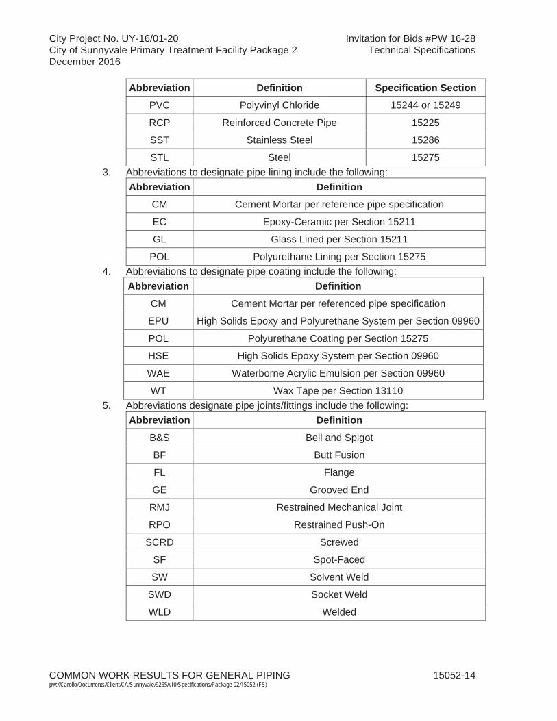
City Project No. UY-16/01-20 Invitation for Bids #PW 16-28City of Sunnyvale Primary Treatment Facility Package 2 Technical SpecificationsDecember 2016
COMMON WORK RESULTS FOR GENERAL PIPING 15052-14pw://Carollo/Documents/Client/CA/Sunnyvale/9265A10/Specifications/Package 02/15052 (FS)
Abbreviation Definition Specification SectionPVC Polyvinyl Chloride 15244 or 15249
RCP Reinforced Concrete Pipe 15225
SST Stainless Steel 15286
STL Steel 152753. Abbreviations to designate pipe lining include the following:
Abbreviation Definition
CM Cement Mortar per reference pipe specification
EC Epoxy-Ceramic per Section 15211
GL Glass Lined per Section 15211
POL Polyurethane Lining per Section 152754. Abbreviations to designate pipe coating include the following:
Abbreviation Definition
CM Cement Mortar per referenced pipe specification
EPU High Solids Epoxy and Polyurethane System per Section 09960
POL Polyurethane Coating per Section 15275
HSE High Solids Epoxy System per Section 09960
WAE Waterborne Acrylic Emulsion per Section 09960
WT Wax Tape per Section 131105. Abbreviations designate pipe joints/fittings include the following:
Abbreviation DefinitionB&S Bell and Spigot
BF Butt Fusion
FL Flange
GE Grooved End
RMJ Restrained Mechanical Joint
RPO Restrained Push-On
SCRD Screwed
SF Spot-Faced
SW Solvent Weld
SWD Socket Weld
WLD Welded

City Project No. UY-16/01-20 Invitation for Bids #PW 16-28City of Sunnyvale Primary Treatment Facility Package 2 Technical SpecificationsDecember 2016
COMMON WORK RESULTS FOR GENERAL PIPING 15052-15pw://Carollo/Documents/Client/CA/Sunnyvale/9265A10/Specifications/Package 02/15052 (FS)
6. Other Useful Abbreviations:Abbreviation Definition
< Less Than
Less Than or Equal To
> Greater Than
Greater Than or Equal To
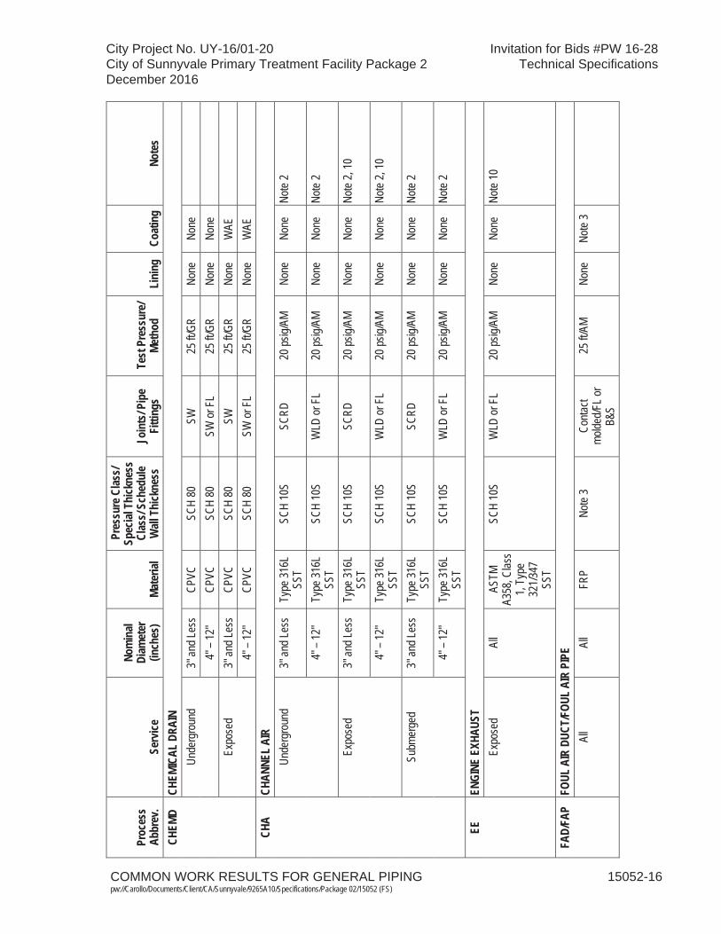
COMMON WORK RESULTS FOR GENERAL PIPING 15052-16pw://Carollo/Documents/Client/CA/Sunnyvale/9265A10/Specifications/Package 02/15052 (FS)
City Project No. UY-16/01-20 Invitation for Bids #PW 16-28City of Sunnyvale Primary Treatment Facility Package 2 Technical SpecificationsDecember 2016
Proc
ess
Abbr
ev.
Serv
ice
Nom
inal
Diam
eter
(in
ches
)Ma
teria
l
Pres
sure
Clas
s/Sp
ecial
Thi
ckne
ss
Clas
s/Sc
hedu
le W
all T
hick
ness
Join
ts/P
ipe
Fitti
ngs
Test
Pre
ssur
e/Me
thod
Lini
ngCo
atin
gNo
tes
CHEM
DCH
EMIC
AL D
RAIN
Unde
rgro
und
3" an
d Les
s CP
VC
SCH
80
SW
25 ft/
GR
None
No
ne
4"
– 12
" CP
VC
SCH
80
SW or
FL
25 ft/
GR
None
No
ne
Ex
pose
d 3"
and L
ess
CPVC
SC
H 80
SW
25
ft/GR
No
ne
WAE
4" –
12"
CPVC
SC
H 80
SW
or F
L 25
ft/GR
No
ne
WAE
CHA
CHAN
NEL
AIR
Unde
rgro
und
3" an
d Les
s Ty
pe 31
6L
SST
SCH
10S
SCRD
20
psig/
AM
None
No
ne
Note
2
4" –
12"
Type
316L
SS
T SC
H 10
S W
LD or
FL
20 ps
ig/AM
No
ne
None
No
te 2
Expo
sed
3" an
d Les
s Ty
pe 31
6L
SST
SCH
10S
SCRD
20
psig/
AM
None
No
ne
Note
2, 10
4" –
12"
Type
316L
SS
T SC
H 10
S W
LD or
FL
20 ps
ig/AM
No
ne
None
No
te 2,
10
Subm
erge
d 3"
and L
ess
Type
316L
SS
T SC
H 10
S SC
RD
20 ps
ig/AM
No
ne
None
No
te 2
4" –
12"
Type
316L
SS
T SC
H 10
S W
LD or
FL
20 ps
ig/AM
No
ne
None
No
te 2
EEEN
GINE
EXH
AUST
Ex
pose
d Al
l AS
TM
A358
, Clas
s 1,
Type
32
1/347
SS
T
SCH
10S
WLD
or F
L 20
psig/
AM
None
No
ne
Note
10
FAD/
FAP
FOUL
AIR
DUC
T/FO
UL A
IR P
IPE
All
All
FRP
Note
3 Co
ntact
molde
d/FL o
r B&
S
25 ft/
AM
None
No
te 3

COMMON WORK RESULTS FOR GENERAL PIPING 15052-17pw://Carollo/Documents/Client/CA/Sunnyvale/9265A10/Specifications/Package 02/15052 (FS)
City Project No. UY-16/01-20 Invitation for Bids #PW 16-28City of Sunnyvale Primary Treatment Facility Package 2 Technical SpecificationsDecember 2016
Proc
ess
Abbr
ev.
Serv
ice
Nom
inal
Diam
eter
(in
ches
)Ma
teria
l
Pres
sure
Clas
s/Sp
ecial
Thi
ckne
ss
Clas
s/Sc
hedu
le W
all T
hick
ness
Join
ts/P
ipe
Fitti
ngs
Test
Pre
ssur
e/Me
thod
Lini
ngCo
atin
gNo
tes
FCFE
RRIC
CHL
ORID
E Un
derg
roun
d 3"
and L
ess
PVC
SCH
80
SW
50 ps
ig/HH
No
ne
None
No
te 4
Expo
sed I
nside
of
Chem
ical C
ontai
nmen
t Ar
ea
3" an
d Les
s CP
VC
SCH
80
SW
50 ps
ig/HH
No
ne
WAE
Expo
sed O
utside
of
Chem
ical C
ontai
nmen
t Ar
ea
3" an
d Les
s CP
VC
SCH
80
SW
50 ps
ig/HH
No
ne
WAE
No
te 4
FOR
FUEL
OIL
RET
URN
Unde
rgro
und
All
BSP,
Pi
ckled
SC
H 40
SC
RD
50 ps
ig/AM
No
ne
WT
Notes
4, 5
Expo
sed
All
BSP,
Pi
ckled
SC
H 40
SC
RD
50 ps
ig/AM
No
ne
EPU
FOS
FUEL
OIL
SUP
PLY
Unde
rgro
und
All
BSP,
Pi
ckled
SC
H 40
SC
RD
50 ps
ig/AM
No
ne
WT
Notes
4,5
Expo
sed
All
BSP,
Pi
ckled
SC
H 40
SC
RD
50 ps
ig/AM
No
ne
EPU
FWFI
RE W
ATER
Unde
rgro
und
6" –
12"
PVC
C900
RP
O 10
0 psig
/HH
None
No
ne/ W
T No
te 5
GRGR
ITUn
derg
roun
d 4"
– 12
" DI
P Cl
ass 5
1 RP
O or
RMJ
50
psig/
HH
GL
WT
Note
5, 11
Ex
pose
d 4"
– 12
" DI
P Cl
ass 5
3 GE
50
psig/
HH
GL
EPU
Note
11
HWHO
T W
ATER
(FRO
M HO
T W
ATER
HEA
TER)
Unde
rgro
und
3" an
d Les
s GS
P SC
H 40
SC
RD
75 ps
ig/HH
No
ne
WT
Notes
5, 6,
12
4" –
12"
BSP
SCH
40
WLD
75
psig/
HH
None
W
T No
tes 5,
6, 12
Ex
pose
d 3"
and L
ess
GSP
SCH
40
SCRD
75
psig/
HH
None
No
ne
Notes
6, 10
4"
– 12
" GS
P SC
H 40
GE
or F
L 75
psig/
HH
None
No
ne
Notes
6, 10

COMMON WORK RESULTS FOR GENERAL PIPING 15052-18pw://Carollo/Documents/Client/CA/Sunnyvale/9265A10/Specifications/Package 02/15052 (FS)
City Project No. UY-16/01-20 Invitation for Bids #PW 16-28City of Sunnyvale Primary Treatment Facility Package 2 Technical SpecificationsDecember 2016
Proc
ess
Abbr
ev.
Serv
ice
Nom
inal
Diam
eter
(in
ches
)Ma
teria
l
Pres
sure
Clas
s/Sp
ecial
Thi
ckne
ss
Clas
s/Sc
hedu
le W
all T
hick
ness
Join
ts/P
ipe
Fitti
ngs
Test
Pre
ssur
e/Me
thod
Lini
ngCo
atin
gNo
tes
HPW
HOT
PRES
SURE
WAT
ER (W
ATER
HEA
TER
AND
HIGH
PRE
SSUR
E W
ASHE
R)
Unde
rgro
und
1" an
d Les
s Ty
pe 30
4L
SST
SCH
80
SWD
3,000
psig/
HH
None
No
ne
Notes
2, 6,
12
Expo
sed
1" an
d Les
s Ty
pe 30
4L
SST
SCH
80
SWD
3,000
psig/
HH
None
No
ne
Notes
2, 6,
10
HWR
HOT
WAT
ER R
ETUR
N Un
derg
roun
d 3"
and L
ess
GSP
SCH
40
SCRD
10
0 psig
/HH
None
W
T No
tes 5,
6, 12
4"
– 12
" BS
P SC
H 40
W
LD
100 p
sig/H
H No
ne
WT
Notes
5, 6,
12
Expo
sed
3" an
d Les
s GS
P SC
H 40
SC
RD
100 p
sig/H
H No
ne
None
No
tes 6,
10
4" –
12"
BSP
SCH
40
FL
100 p
sig/H
H No
ne
None
No
tes 6,
10
HWS
HOT
WAT
ER S
UPPL
Y Un
derg
roun
d 3"
and L
ess
GSP
SCH
40
SCRD
10
0 psig
/HH
None
W
T No
tes 5,
6, 12
4"
– 12
" BS
P SC
H 40
W
LD
100 p
sig/H
H No
ne
WT
Notes
5, 6,
12
Expo
sed
3" an
d Les
s GS
P SC
H 40
SC
RD
100 p
sig/H
H No
ne
None
No
tes 6,
10
4" –
12"
BSP
SCH
40
FL
100 p
sig/H
H No
ne
None
No
tes 6,
10
IAIN
STRU
MENT
AIR
Al
l 3"
and L
ess
Type
304L
SS
T SC
H 40
SC
RD
125 p
sig/A
M No
ne
None
No
te 2
NGNA
TURA
L GA
S Un
derg
roun
d Al
l PE
AS
TM D
2513
, SD
R 11
BF
or S
F 25
psig/
AM
None
No
ne
Expo
sed
3" an
d Les
s BS
P SC
H 40
W
LD or
FL
25 ps
ig/AM
No
ne
EPU
4"
– 12
" BS
P SC
H 40
W
LD or
FL
25 ps
ig/AM
No
ne
EPU
NS
NUTR
IENT
SUP
PLY
Expo
sed
4" an
d Les
s PV
C SC
H 80
SW
10
0 psig
/HH
None
W
AE
Su
bmer
ged
4" an
d Les
s PV
C SC
H 80
SW
10
0 psig
/HH
None
W
AE

COMMON WORK RESULTS FOR GENERAL PIPING 15052-19pw://Carollo/Documents/Client/CA/Sunnyvale/9265A10/Specifications/Package 02/15052 (FS)
City Project No. UY-16/01-20 Invitation for Bids #PW 16-28City of Sunnyvale Primary Treatment Facility Package 2 Technical SpecificationsDecember 2016
Proc
ess
Abbr
ev.
Serv
ice
Nom
inal
Diam
eter
(in
ches
)Ma
teria
l
Pres
sure
Clas
s/Sp
ecial
Thi
ckne
ss
Clas
s/Sc
hedu
le W
all T
hick
ness
Join
ts/P
ipe
Fitti
ngs
Test
Pre
ssur
e/Me
thod
Lini
ngCo
atin
gNo
tes
NSR
NUTR
IENT
SUP
PLY
RETU
RN
Expo
sed
3" an
d Les
s PV
C SC
H 80
SW
10
0 psig
/HH
None
W
AE
Su
bmer
ged
3" an
d Les
s PV
C SC
H 80
SW
10
0 psig
/HH
None
W
AE
PD
PUMP
ED D
RAIN
Un
derg
roun
d 3"
and L
ess
PVC
SCH
80
SW
50 ps
ig/HH
No
ne
None
No
te 5
4" –
12"
PVC
C900
RP
O or
RMJ
50
psig/
HH
None
No
ne/ W
T No
te 5
Expo
sed
3" an
d Les
s GS
P SC
H 40
SC
RD
50 ps
ig/HH
No
ne
EPU
4"
– 12
" DI
P Cl
ass 5
3 FL
or G
E 50
psig/
HH
CM
EPU
Su
bmer
ged
3" an
d Les
s GS
P SC
H 40
SC
RD
50 ps
ig/HH
No
ne
EPU
4"
– 12
" DI
P Cl
ass 5
3 FL
or G
E 50
psig/
HH
CM
EPU
PE
PRIM
ARY
EFFL
UENT
Unde
rgro
und
4" –
63"
HDPE
DR
26
BF (F
L whe
re
show
n)
50 ps
ig/LH
No
ne
None
Unde
rgro
und -
Whe
n No
ted on
Dra
wing
s 36
" and
Abo
ve
STL
AWW
A C2
00
WLD
or F
L 50
psig/
LH
CM
POL
unde
r WT
Note
13
PEC
PRIM
ARY
EFFL
UENT
CAS
ING
Unde
rgro
und
72"
STL
ASTM
A13
9, Gr
ade
B W
LD
N/A
None
No
ne
POLY
POLY
MER
Unde
rgro
und
All
PVC
SCH
80
SW
125 p
sig/H
H No
ne
None
Expo
sed
All
CPVC
SC
H 80
SW
12
5 psig
/HH
None
W
AE
Note
8 Su
bmer
ged
All
PVC
SCH
80
SW
125 p
sig/H
H No
ne
WAE
No
te 8
PSC
PRIM
ARY
SCUM
Unde
rgro
und
4" –
12"
DIP
Clas
s 51
RPO
50 ps
ig/HH
GL
W
T No
tes 5,
11
Expo
sed
4" –
12"
DIP
Clas
s 53
GE
50 ps
ig/HH
GL
EP
U No
te 11
Su
bmer
ged
4" –
12"
DIP
Clas
s 53
GE
50 ps
ig/HH
GL
EP
U No
te 11
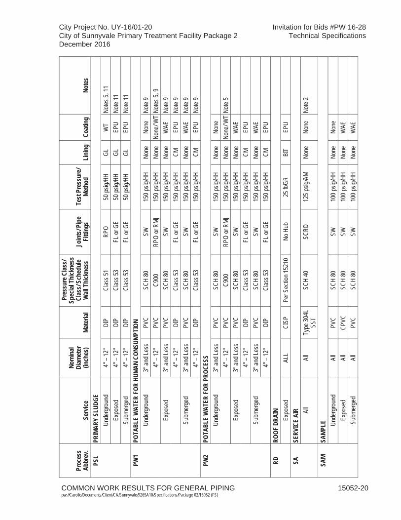
COMMON WORK RESULTS FOR GENERAL PIPING 15052-20pw://Carollo/Documents/Client/CA/Sunnyvale/9265A10/Specifications/Package 02/15052 (FS)
City Project No. UY-16/01-20 Invitation for Bids #PW 16-28City of Sunnyvale Primary Treatment Facility Package 2 Technical SpecificationsDecember 2016
Proc
ess
Abbr
ev.
Serv
ice
Nom
inal
Diam
eter
(in
ches
)Ma
teria
l
Pres
sure
Clas
s/Sp
ecial
Thi
ckne
ss
Clas
s/Sc
hedu
le W
all T
hick
ness
Join
ts/P
ipe
Fitti
ngs
Test
Pre
ssur
e/Me
thod
Lini
ngCo
atin
gNo
tes
PSL
PRIM
ARY
SLUD
GEUn
derg
roun
d 4"
– 12
" DI
P Cl
ass 5
1 RP
O 50
psig/
HH
GL
WT
Notes
5, 11
Ex
pose
d 4"
– 12
" DI
P Cl
ass 5
3 FL
or G
E 50
psig/
HH
GL
EPU
Note
11
Subm
erge
d 4"
– 12
" DI
P Cl
ass 5
3 FL
or G
E 50
psig/
HH
GL
EPU
Note
11
PW1
POTA
BLE
WAT
ERFO
R HU
MAN
CONS
UMPT
ION
Unde
rgro
und
3" an
d Les
s PV
C SC
H 80
SW
15
0 psig
/HH
None
No
ne
Note
9 4"
– 12
" PV
C C9
00
RPO
or R
MJ
150 p
sig/H
H No
ne
None
/ WT
Notes
5, 9
Expo
sed
3" an
d Les
s PV
C SC
H 80
SW
15
0 psig
/HH
None
W
AE
Note
9 4"
– 12
" DI
P Cl
ass 5
3 FL
or G
E 15
0 psig
/HH
CM
EPU
Note
9 Su
bmer
ged
3" an
d Les
s PV
C SC
H 80
SW
15
0 psig
/HH
None
W
AE
Note
9 4"
– 12
" DI
P Cl
ass 5
3 FL
or G
E 15
0 psig
/HH
CM
EPU
Note
9 PW
2PO
TABL
E W
ATER
FOR
PROC
ESS
Unde
rgro
und
3" an
d Les
s PV
C SC
H 80
SW
15
0 psig
/HH
None
No
ne
4"
– 12
" PV
C C9
00
RPO
or R
MJ
150 p
sig/H
H No
ne
None
/ WT
Note
5 Ex
pose
d 3"
and L
ess
PVC
SCH
80
SW
150 p
sig/H
H No
ne
WAE
4" –
12"
DIP
Clas
s 53
FL or
GE
150 p
sig/H
H CM
EP
U
Subm
erge
d 3"
and L
ess
PVC
SCH
80
SW
150 p
sig/H
H No
ne
WAE
4" –
12"
DIP
Clas
s 53
FL or
GE
150 p
sig/H
H CM
EP
U
RDRO
OF D
RAIN
Expo
sed
ALL
CISP
Pe
r Sec
tion 1
5210
No
Hub
25
ft/GR
BI
T EP
U
SASE
RVIC
E AI
R All
All
Type
304L
SS
T SC
H 40
SC
RD
125 p
sig/A
M No
ne
None
No
te 2
SAM
SAMP
LE Unde
rgro
und
All
PVC
SCH
80
SW
100 p
sig/H
H No
ne
None
Expo
sed
All
CPVC
SC
H 80
SW
10
0 psig
/HH
None
W
AE
Su
bmer
ged
All
PVC
SCH
80
SW
100 p
sig/H
H No
ne
WAE
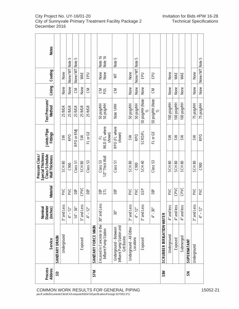
COMMON WORK RESULTS FOR GENERAL PIPING 15052-21pw://Carollo/Documents/Client/CA/Sunnyvale/9265A10/Specifications/Package 02/15052 (FS)
City Project No. UY-16/01-20 Invitation for Bids #PW 16-28City of Sunnyvale Primary Treatment Facility Package 2 Technical SpecificationsDecember 2016
Proc
ess
Abbr
ev.
Serv
ice
Nom
inal
Diam
eter
(in
ches
)Ma
teria
l
Pres
sure
Clas
s/Sp
ecial
Thi
ckne
ss
Clas
s/Sc
hedu
le W
all T
hick
ness
Join
ts/P
ipe
Fitti
ngs
Test
Pre
ssur
e/Me
thod
Lini
ngCo
atin
gNo
tes
SDSA
NITA
RY D
RAIN
Unde
rgro
und
3" an
d Les
s PV
C SC
H 80
SW
25
ft/GR
No
ne
None
4" –
12"
PVC
C900
RP
O 25
ft/GR
No
ne
None
/ WT
Note
5 14
" - 36
" DI
P Cl
ass 5
1
RPO
or R
MJ
25 ft/
GR
CM
None
/ WT
Note
5 Ex
pose
d 3"
and L
ess
CPVC
SC
H 80
SW
25
ft/GR
No
ne
WAE
4" –
12"
DIP
Clas
s 53
FL or
GE
25 ft/
GR
CM
EPU
SF
MSA
NITA
RY F
ORCE
MAI
NEn
case
d in C
oncre
te in
the
Influe
nt Pu
mp S
tation
30
" and
Less
DI
P ST
L Cl
ass 5
3 1/2
" Thic
k Wall
FL
W
LD (F
L whe
re
show
n)
50 ps
ig/HH
50
psig/
HH
CM
POL
None
No
ne
Note
16
Note
16
Unde
rgro
und -
Betw
een
Influe
nt Pu
mp S
tation
and
Grit B
asins
30"
DIP
Clas
s 51
RPO
(FL w
here
sh
own)
No
te 1/H
H CM
W
T No
te 5
Unde
rgro
und -
All O
ther
Loca
tions
3"
and L
ess
PVC
SCH
80
SW
50 ps
ig/HH
No
ne
None
4" -
12"
PVC
C900
RP
O 50
psig/
HH
None
No
ne/ W
T No
te 5
Expo
sed
3" an
d Les
s GS
P SC
H 40
SC
RD/F
L 50
psig/
HH (N
ote
1)
None
EP
U
4" -
30"
DIP
Clas
s 53
FL or
GE
50 ps
ig/HH
(Note
1)
CM
EP
U
SIW
SCRU
BBER
IRRI
GATI
ON W
ATER
Un
derg
roun
d 4"
and l
ess
PVC
SCH
80
SW
100 p
sig/H
H No
ne
None
Expo
sed
4" an
d les
s CP
VC
SCH
80
SW
100 p
sig/H
H No
ne
WAE
Subm
erge
d 4"
and l
ess
CPVC
SC
H 80
SW
10
0 psig
/HH
None
W
AE
SN
SUPE
RNAT
ANT
Unde
rgro
und
3" an
d Les
s PV
C SC
H 80
SW
75
psig/
HH
None
No
ne
4"
– 12
" PV
C C9
00
RPO
75 ps
ig/HH
No
ne
None
/ WT
Note
5

COMMON WORK RESULTS FOR GENERAL PIPING 15052-22pw://Carollo/Documents/Client/CA/Sunnyvale/9265A10/Specifications/Package 02/15052 (FS)
City Project No. UY-16/01-20 Invitation for Bids #PW 16-28City of Sunnyvale Primary Treatment Facility Package 2 Technical SpecificationsDecember 2016
Proc
ess
Abbr
ev.
Serv
ice
Nom
inal
Diam
eter
(in
ches
)Ma
teria
l
Pres
sure
Clas
s/Sp
ecial
Thi
ckne
ss
Clas
s/Sc
hedu
le W
all T
hick
ness
Join
ts/P
ipe
Fitti
ngs
Test
Pre
ssur
e/Me
thod
Lini
ngCo
atin
gNo
tes
SSSA
NITA
RY S
EWER
Unde
rgro
und
MH 17
to IJ
B,
IJB to
Scre
ening
Fac
ility
66"
RCPP
30
-ft in
terna
l pr
essu
re,
AWW
A C3
02, M
9
Pipe
: BS-
DG,
Beve
l Jt:
Carn
egie-
DG,
Shor
t Spo
ols:
Carn
egie
DG
LH / J
oint T
est
with
Wate
r No
te 7
None
De
sign p
ipe fo
r H20
loa
ding u
nder
20 ft
cove
r and
grou
ndwa
ter
pres
sure
whe
re pi
pe is
be
low gr
ound
water
ele
vatio
n per
Sec
tion
0220
0; 16
ft ma
x. sp
ool le
ngth
Unde
rgro
und,
MH15
to IJ
B 48
" RC
PP
30-ft
inter
nal
pres
sure
, AW
WA
C302
, M9
Pipe
: BS-
DG
LH / J
oint T
est
with
water
No
te 7
None
H2
0 loa
ding u
nder
20
ft cov
er an
d gr
ound
water
pres
sure
wh
ere p
ipe is
below
gr
ound
water
elev
ation
pe
r Sec
tion 0
2200
ST
DST
ORM
DRAI
NUn
derg
roun
d 4"
– 12
" PV
C AW
WA
C900
Pu
sh-o
n GR
No
ne
None
No
te 5,
Note
15
14" –
36"
PVC
AWW
A C9
05
Push
-on
GR
None
No
ne
Note
5, No
te 15
TD
TANK
DRA
INUn
derg
roun
d 3"
and L
ess
PVC
SCH
80
SW
25 ps
ig/LH
No
ne
None
4" –
12"
PVC
C900
RP
O 25
psig/
LH
None
No
ne/ W
T No
te 5
Expo
sed
3" an
d Les
s PV
C SC
H 80
SW
25
psig/
LH
None
W
AE
4"
– 12
" DI
P Cl
ass 5
3 FL
or G
E 25
psig/
LH
CM
EPU
UW
UTIL
ITY
WAT
ERUn
derg
roun
d 3"
and L
ess
PVC
SCH
80
SW
150 p
sig/H
H No
ne
None
4" –
12"
PVC
C900
RP
O 15
0 psig
/HH
None
No
ne/ W
T No
te 5
Expo
sed
3" an
d Les
s CP
VC
SCH
80
SW
150 p
sig/H
H No
ne
WAE
4" –
12"
DIP
Clas
s 53
FL or
GE
150 p
sig/H
H CM
EP
U
Subm
erge
d 3"
and L
ess
PVC
SCH
80
SW
150 p
sig/H
H No
ne
WAE
4" –
12"
DIP
Clas
s 53
FL or
GE
150 p
sig/H
H CM
EP
U
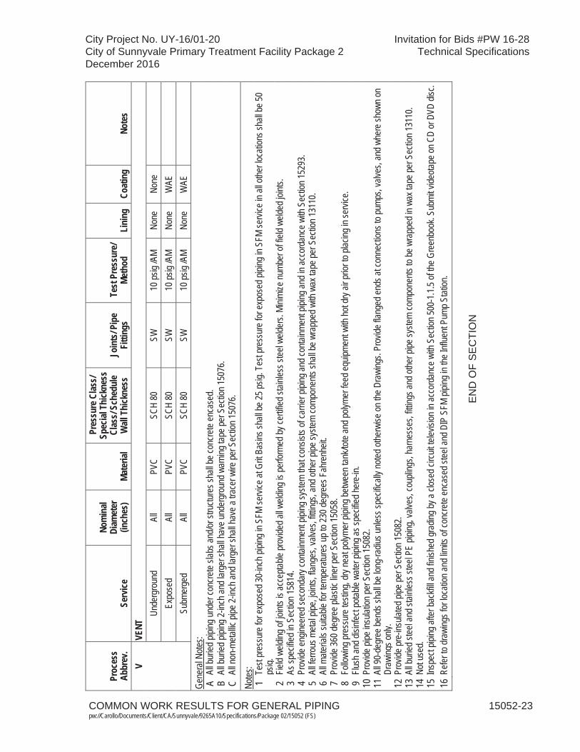
COMMON WORK RESULTS FOR GENERAL PIPING 15052-23pw://Carollo/Documents/Client/CA/Sunnyvale/9265A10/Specifications/Package 02/15052 (FS)
City Project No. UY-16/01-20 Invitation for Bids #PW 16-28City of Sunnyvale Primary Treatment Facility Package 2 Technical SpecificationsDecember 2016
Proc
ess
Abbr
ev.
Serv
ice
Nom
inal
Diam
eter
(in
ches
)Ma
teria
l
Pres
sure
Clas
s/Sp
ecial
Thi
ckne
ss
Clas
s/Sc
hedu
le W
all T
hick
ness
Join
ts/P
ipe
Fitti
ngs
Test
Pre
ssur
e/Me
thod
Lini
ngCo
atin
gNo
tes
VVE
NTUn
derg
roun
d Al
l PV
C SC
H 80
SW
10
psig
/AM
None
No
ne
Ex
pose
d Al
l PV
C SC
H 80
SW
10
psig
/AM
None
W
AE
Su
bmer
ged
All
PVC
SCH
80
SW
10 ps
ig /A
M No
ne
WAE
Gene
ral N
otes:
A Al
l bur
ied pi
ping u
nder
conc
rete
slabs
and/o
r stru
cture
s sha
ll be c
oncre
te en
case
d. B
All b
uried
pipin
g 2-in
ch an
d lar
ger s
hall h
ave u
nder
grou
nd w
arnin
g tap
e per
Sec
tion 1
5076
. C
All n
on-m
etallic
pipe
2-inc
h and
larg
er sh
all ha
ve a
trace
r wire
per S
ectio
n 150
76.
Notes
: 1
Test
pres
sure
for e
xpos
ed 30
-inch
pipin
g in S
FM se
rvice
at G
rit Ba
sins s
hall b
e 25 p
sig. T
est p
ress
ure f
or ex
pose
d pipi
ng in
SFM
servi
ce in
all o
ther lo
catio
ns sh
all be
50
psig.
2
Field
weldi
ng of
joint
s is a
ccep
table
prov
ided a
ll weld
ing is
perfo
rmed
by ce
rtified
stain
less s
teel w
elder
s. Mi
nimize
numb
er of
field
welde
d join
ts.
3 As
spec
ified i
n Sec
tion 1
5814
. 4
Prov
ide en
ginee
red s
econ
dary
conta
inmen
t pipi
ng sy
stem
that c
onsis
ts of
carri
er pi
ping a
nd co
ntainm
ent p
iping
and i
n acc
orda
nce w
ith S
ectio
n 152
93.
5 Al
l ferro
us m
etal p
ipe, jo
ints,
flang
es, v
alves
, fittin
gs, a
nd ot
her p
ipe sy
stem
comp
onen
ts sh
all be
wra
pped
with
wax
tape
per S
ectio
n 131
10.
6 Al
l mate
rials
suita
ble fo
r tem
pera
tures
up to
230 d
egre
es F
ahre
nheit
. 7
Prov
ide 36
0 deg
ree p
lastic
liner
per S
ectio
n 150
58.
8 Fo
llowi
ng pr
essu
re te
sting
, dry
neat
polym
er pi
ping b
etwee
n tan
k/tote
and p
olyme
r fee
d equ
ipmen
t with
hot d
ry air
prior
to pl
acing
in se
rvice
. 9
Flush
and d
isinfe
ct po
table
water
pipin
g as s
pecif
ied he
re-in
. 10
Pro
vide p
ipe in
sulat
ion pe
r Sec
tion 1
5082
. 11
All 9
0-de
gree
bend
s sha
ll be l
ong-
radiu
s unle
ss sp
ecific
ally n
oted o
therw
ise on
the D
rawi
ngs.
Prov
ide fla
nged
ends
at co
nnec
tions
to pu
mps,
valve
s, an
d whe
re sh
own o
n Dr
awing
s only
. 12
Pro
vide p
re-in
sulat
ed pi
pe pe
r Sec
tion 1
5082
. 13
All b
uried
stee
l and
stain
less s
teel P
E pip
ing, v
alves
, cou
pling
s, ha
rnes
ses,
fitting
s and
othe
r pipe
syste
m co
mpon
ents
to be
wra
pped
in w
ax ta
pe pe
r Sec
tion 1
3110
. 14
Not
used
. 15
Insp
ect p
iping
after
back
fill an
d fini
shed
grad
ing by
a clo
sed c
ircuit
telev
ision
in ac
cord
ance
with
Sec
tion 5
00-1
.1.5 o
f the G
reen
book
. Sub
mit v
ideota
pe on
CD
or D
VD di
sc.
16 R
efer t
o dra
wing
s for
loca
tion a
nd lim
its of
conc
rete
enca
sed s
teel a
nd D
IP S
FM pi
ping i
n the
Influ
ent P
ump S
tation
.
EN
D O
F S
EC
TIO
N

City Project No. UY-16/01-20 Invitation for Bids #PW 16-28City of Sunnyvale Primary Treatment Facility Package 2 Technical SpecificationsDecember 2016
SEISMIC RESTRAINTS FOR PIPING 15053-1 pw://Carollo/Documents/Client/CA/Sunnyvale/9265A10/Specifications/Package 02/15053 (FS)
SECTION 15053
SEISMIC RESTRAINTS FOR PIPING
PART 1 GENERAL
1.01 SUMMARY
A. This Section specifies seismic restraints for bracing all piping and ductwork: 1. This Section does not include seismic restraints for fire sprinkler systems.
B. Related Sections:1. The Contract Documents are complementary; what is called for by one is as
binding as if called for by all.2. It is the Contractor's responsibility for scheduling and coordinating the Work of
subcontractors, suppliers, and other individuals or entities performing or furnishing any of Contractor's Work.
3. The following Sections are related to the Work described in this Section. This list of Related Sections is provided for convenience only and is not intended to excuse or otherwise diminish the duty of the Contractor to see that the completed Work complies accurately with the Contract Documents: a. Section 01060 – Regulatory Permits and Requirements.b. Section 01612 - Seismic Design Criteria.c. Section 05190 – Mechanical Anchoring and Fastening to Concrete and
Masonry.d. Section 15052 - Common Work Results for General Piping. e. Section 15054 - Expansion Control for Piping.f. Section 15061 - Pipe Supports.
C. Operating Conditions:1. Seismic restraints specified in this Section are provided to resist pipe
movements and loads that result from an earthquake or other seismic event.2. All piping systems shall be provided with seismic restraints conforming to
governing state and local codes.3. Seismic restraints shall conform to guidelines given in the Sheet Metal and Air
Conditioning Contractors' National Association (SMACNA) Seismic Restraint Manual for the Seismic Hazard Level specified in Section 01612 and, at a minimum, be consistent with requirements of governing state and local codes.
4. In case of conflict, the more stringent requirements specified in Section 01612or governing state or local code shall be followed.
D. Restraint Selection:1. Piping systems shall not be braced to dissimilar parts of a building or to
dissimilar building systems that may respond in a different mode during an earthquake. Examples: wall and a roof; solid concrete wall and a metal deck with lightweight concrete fill.
2. Restraints shall be sized to fit outside diameter of pipe, tubing, or, where specified, outside diameter of insulation.
City Project No. UY-16/01-20 Invitation for Bids #PW 16-28City of Sunnyvale Primary Treatment Facility Package 2 Technical SpecificationsDecember 2016
SEISMIC RESTRAINTS FOR PIPING 15053-2 pw://Carollo/Documents/Client/CA/Sunnyvale/9265A10/Specifications/Package 02/15053 (FS)
3. There shall be no contact between a pipe and restraint component of dissimilar metals. Contractor shall prevent contact between dissimilar metals when restraining copper tubing by using copper-plated, rubber, plastic or vinyl-coated, or stainless steel restraint components.
4. Branch lines shall not be used to brace main lines.5. Seismic bracing shall not limit expansion and contraction of the piping system.
1.02 REFERENCES
A. American Institute of Steel Construction (AISC):1. Manual of Steel Construction, Allowable Stress Design - 9th Edition.
B. Metal Framing Manufacturers Association (MFMA):1. MFMA-2 - Metal Framing Standards Publication.2. MFMA-101 - Guidelines for the Use of Metal Framing.
C. American National Standard Institute or Manufacturer's Standardization Society (ANSI/MSS): 1. SP-58 - Standard for Pipe Hangers and Supports - Materials, Design, and
Manufacture.2. SP-69 - Standard for Pipe Hangers and Supports - Selection and Application.3. SP-89 - Standard for Pipe Hangers and Supports - Fabrication and Installation
Practices.
D. American National Standard Institute/National Fire Protection Association: 1. ANSI/NFPA 70.
E. National Fire Protection Association (NFPA): 1. NFPA 13 - Installation of Sprinkler Systems.2. NFPA 14 - Standpipe and Hose Systems.
F. Sheet Metal and Air Conditioning Contractors' National Association (SMACNA):1. Seismic Restraint Guidelines for Mechanical Systems.
1.03 DEFINITIONS
A. Longitudinal Direction: Direction parallel to the pipe axis.
B. Lateral Direction: Direction perpendicular to the pipe axis.
1.04 DESIGN
A. Seismic restraint system shall be designed by the Design Professional as required in Section 15061.
B. Seismic restraint details shall be designed in conjunction with preparation of pipe system hangers and drawings.
City Project No. UY-16/01-20 Invitation for Bids #PW 16-28City of Sunnyvale Primary Treatment Facility Package 2 Technical SpecificationsDecember 2016
SEISMIC RESTRAINTS FOR PIPING 15053-3 pw://Carollo/Documents/Client/CA/Sunnyvale/9265A10/Specifications/Package 02/15053 (FS)
1.05 SUBMITTALS
A. Per Section 15061.
1.06 QUALITY ASSURANCE
A. Submit inspection reports as defined in Section 15061.
1.07 PROJECT CONDITIONS
A. Environmental requirements as specified in Section 01610.
PART 2 PRODUCTS
2.01 MANUFACTURERS
A. Standard pipe restraints and components shall be manufactured by Carpenter & Patterson, B-Line, Kin-Line, ITT Grinnell, Michigan, Pipe Shields Incorporated, Superstrut, Unistrut, or equal.
B. Pipe restraint materials, design, manufacture, testing, installation, and application shall conform to the requirements of MSS SP-58, MSS-SP-69, MSS-SP-89,MFMA-2, and MFMA-101.
2.02 MATERIALS
A. Unless otherwise specified, restraints, including braces, pipe and structural attachments, shall match the pipe support material as specified in Section 15061.
B. Nuts, bolts, and washers shall match materials specified for the nuts, bolts, andwashers in Section 15061.
C. Concrete anchors shall be per Section 15061.
D. For corrosive areas specifically requiring fiberglass materials. In those areas, all pipe support, anchor, and brace components (not just fittings and accessories) shall be made of fiberglass.
2.03 THERMAL PIPE HANGER SHIELD
A. Thermal shields shall be provided at seismic restraint locations on pipe requiring insulation.
B. Thermal pipe hanger shields shall be as specified in Section 15061.
C. Stainless steel band clamps shall be provided on thermal shields at longitudinal pipe restraint locations.

City Project No. UY-16/01-20 Invitation for Bids #PW 16-28City of Sunnyvale Primary Treatment Facility Package 2 Technical SpecificationsDecember 2016
SEISMIC RESTRAINTS FOR PIPING 15053-4 pw://Carollo/Documents/Client/CA/Sunnyvale/9265A10/Specifications/Package 02/15053 (FS)
PART 3 EXECUTION
3.01 PIPE RESTRAINT LOCATIONS
A. The first seismic restraint on a piping system shall be located not more than 10 feetfrom the main riser, entrance to a building or piece of equipment.
B. Cast iron pipe shall be braced on each side of a change in direction of 90 degrees or more. Joints in risers shall be braced or stabilized between floors.
C. No-hub and bell-and-spigot cast iron soil pipe shall be braced longitudinally every 20 feet and laterally every 10 feet.
D. Lateral bracing for one pipe section may also act as longitudinal bracing for the pipe section connected perpendicular to it, if the bracing is installed within 24 inches of the elbow or tee of the same size.
3.02 INSTALLATION
A. Rod stiffener assemblies shall be used at seismic restraints for hanger rods over 6 inches in length.
B. A minimum of two-rod stiffener clamps shall be used on any rod stiffener assembly.
C. Lateral and longitudinal bracing shall be installed between 45 degrees above and45 degrees below horizontal, inclusive, relative to the horizontal centerline of the pipe.
D. Welded and bolted attachments to the building structural steel shall be in accordance with the requirements of the AISC Manual of Steel Construction.
E. There shall be no drilling or burning of holes in the building structural steel without approval of the Project Inspector.
F. Embedded anchor bolts shall be used instead of concrete inserts for seismic brace installations in areas below water surface or normally subject to submergence.
G. The Contractor shall install thermal pipe hanger shields on insulated piping at required locations during restraint installation.
H. Butt joint connections to pipe insulation shall be made at the time of insulation installation in accordance with the manufacturer's recommendations.
I. Restraint components in contact with plastic pipe shall be free of burrs and sharp edges.
J. Rollers shall roll freely without binding.
K. Plastic or rubber end caps shall be provided at the exposed ends of all framing channels that are located up to 7 feet above the floor.
END OF SECTION

City Project No. UY-16/01-20 Invitation for Bids #PW 16-28City of Sunnyvale Primary Treatment Facility Package 2 Technical SpecificationsDecember 2016
EXPANSION CONTROL FOR PIPING 15054-1 pw://Carollo/Documents/Client/CA/Sunnyvale/9265A10/Specifications/Package 02/15054 (FS)
SECTION 15054
EXPANSION CONTROL FOR PIPING
PART 1 GENERAL
1.01 SUMMARY
A. This section addresses pipe anchorage, pipe guides, and expansion control by either expansion joints or pipe deflection: 1. Provide expansion control for the piping scheduled in this Section.
B. Related sections: 1. The Contract Documents are complementary; what is called for by one is as
binding as if called for by all.2. It is the Contractor's responsibility for scheduling and coordinating the Work of
subcontractors, suppliers, and other individuals or entities performing or furnishing any of Contractor's Work.
3. The following Sections are related to the Work described in this Section. This list of Related Sections is provided for convenience only and is not intended to excuse or otherwise diminish the duty of the Contractor to see that the completed Work complies accurately with the Contract Documents: a. Section 01060 - Regulatory Requirements.b. Section 01612 - Seismic Design Criteria.c. Section 05190 - Mechanical Anchoring and Fastening to Concrete and
Masonry.d. Section 15052 - Common Work Results for General Piping. e. Section 15053 - Seismic Restraints for Piping.f. Section 15061 - Pipe Supports.g. Section 15120 - Piping Specialties.
C. Operating Conditions:1. Expansion control as specified in this Section shall be provided to control pipe
movements and loads occurring as a result of pipeline temperature changes.2. Those piping systems listed in the following table shall be provided with
expansion control conforming to good engineering practice:
Piping SystemMinimum Temperature,
degrees F Maximum Temperature,
degrees F Engine Exhaust (EEX) 45 1,200
Channel Air (CA) 45 300
Hot Water (HW) 45 200
Hot Water Supply (HWS) and Return (HWR)
45 200
Primary Sludge (PSL) and Primary Scum (PSC)
45 120
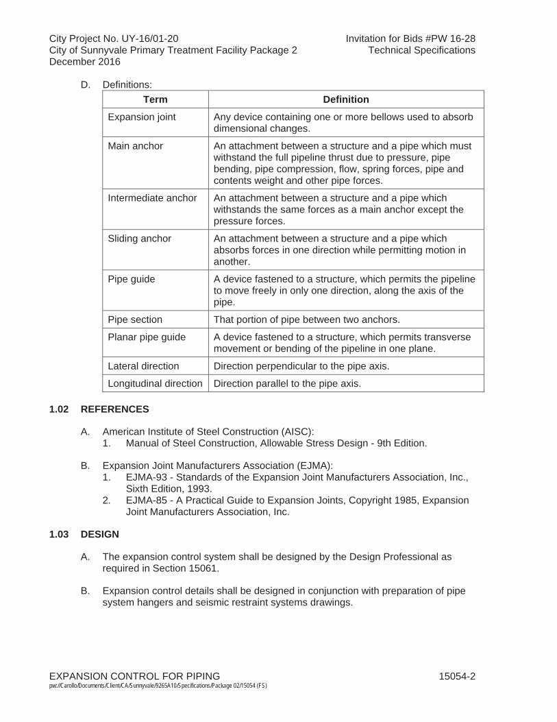
City Project No. UY-16/01-20 Invitation for Bids #PW 16-28City of Sunnyvale Primary Treatment Facility Package 2 Technical SpecificationsDecember 2016
EXPANSION CONTROL FOR PIPING 15054-2 pw://Carollo/Documents/Client/CA/Sunnyvale/9265A10/Specifications/Package 02/15054 (FS)
D. Definitions:Term Definition
Expansion joint Any device containing one or more bellows used to absorb dimensional changes.
Main anchor An attachment between a structure and a pipe which must withstand the full pipeline thrust due to pressure, pipe bending, pipe compression, flow, spring forces, pipe and contents weight and other pipe forces.
Intermediate anchor An attachment between a structure and a pipe which withstands the same forces as a main anchor except the pressure forces.
Sliding anchor An attachment between a structure and a pipe which absorbs forces in one direction while permitting motion in another.
Pipe guide A device fastened to a structure, which permits the pipeline to move freely in only one direction, along the axis of the pipe.
Pipe section That portion of pipe between two anchors.
Planar pipe guide A device fastened to a structure, which permits transverse movement or bending of the pipeline in one plane.
Lateral direction Direction perpendicular to the pipe axis.
Longitudinal direction Direction parallel to the pipe axis.
1.02 REFERENCES
A. American Institute of Steel Construction (AISC):1. Manual of Steel Construction, Allowable Stress Design - 9th Edition.
B. Expansion Joint Manufacturers Association (EJMA):1. EJMA-93 - Standards of the Expansion Joint Manufacturers Association, Inc.,
Sixth Edition, 1993.2. EJMA-85 - A Practical Guide to Expansion Joints, Copyright 1985, Expansion
Joint Manufacturers Association, Inc.
1.03 DESIGN
A. The expansion control system shall be designed by the Design Professional as required in Section 15061.
B. Expansion control details shall be designed in conjunction with preparation of pipe system hangers and seismic restraint systems drawings.
City Project No. UY-16/01-20 Invitation for Bids #PW 16-28City of Sunnyvale Primary Treatment Facility Package 2 Technical SpecificationsDecember 2016
EXPANSION CONTROL FOR PIPING 15054-3 pw://Carollo/Documents/Client/CA/Sunnyvale/9265A10/Specifications/Package 02/15054 (FS)
1.04 DESIGN GUIDELINES
A. The Design Professional shall use the following guidelines: 1. The difference between the minimum and maximum temperatures scheduled. 2. Published coefficients of thermal expansion for pipe materials shall be used for
the listed temperature range: a. The source of the coefficients of expansion used in the calculations shall
be included with the data provided as Product Data.3. Expansion control systems shall be designed for maximum reliability. Unless
otherwise indicated on the Drawings, "L," "U," or "Z" bends shall be employed to control expansion in preference over expansion joints.
4. Expansion control systems using pipe bends shall be designed to limit bending stress in the pipe associated with deflection at the worst-case temperature difference: a. The maximum allowable bending stress shall be 1/3 of the yield stress for
the pipe material.b. If loading conditions or uncertainties warrant, a lower allowable stress
value shall be used.c. A recognized pipe bending stress calculation method and documentation
supporting its use shall be provided as Product Data.5. The requirements set forth in Section 15120 shall prevail if expansion joints
are used. Expansion control design for expansion joints shall conform to theguidelines given in the Standards of The Expansion Joint Manufacturers Association, Inc. (EJMA).
6. If the Design Professional chooses to use expansion control or pipe support methods that involve higher loading on the structure than are indicated on theDrawings, the Engineer shall be notified. The requested loads shall be listed and the Design Professional will redesign the structure as necessary at the Contractor's expense.
7. The test pressures listed in the Piping Schedule of Section 15052 shall be used when calculating pressure forces.
8. Pipe guides or planar pipe guides shall be provided to control the movement of pipes when "L," "U," or "Z" bends are used for expansion control: a. The guides shall be located as indicated in EJMA standards.b. An alternative recognized standard may be used for this purpose only
upon approval by the Engineer. 9. Recommended main anchor locations are shown on the Drawings:
a. Intermediate anchors shall be provided as needed.b. Maximum forces that the structure can withstand at the main anchor
points are noted on the Drawings.c. Anchors shall be designed to attach to the structure and solidly to the
pipe.d. Pipe clamps or U-bolts are not allowed unless they are designed to
withstand the forces imposed upon the anchor and have stops welded to the pipe so that the pipe cannot slip in the anchor.
10. Anchors and guides shall be coordinated with the pipe support system specified in Section 15061 and seismic restraints specified in Section 15053.
City Project No. UY-16/01-20 Invitation for Bids #PW 16-28City of Sunnyvale Primary Treatment Facility Package 2 Technical SpecificationsDecember 2016
EXPANSION CONTROL FOR PIPING 15054-4 pw://Carollo/Documents/Client/CA/Sunnyvale/9265A10/Specifications/Package 02/15054 (FS)
11. The design of the expansion control, pipe supports, and seismic restraints for the listed piping systems shall be integrated to provide maximum flexibility for maintenance access to equipment, appurtenances such as valves, etc., and to the pipe itself.
12. The piping layout indicated shall be reviewed in relation to surrounding structures, adjacent piping, and equipment before selecting the anchors, guides, and expansion control method to be used at each point.
13. There shall be no metal-to-metal contact between a pipe and restraint component of dissimilar metals.
14. Branch lines shall not be used to anchor main lines.15. For elevated pipe sections, fabricated support frames, or other appropriate
structures shall be designed to withstand the specified loads plus gravity and seismic loads.
16. The supports shall be designed to provide access to equipment, walkways, gates, and other piping.
1.05 SUBMITTALS
A. Per Section 15061.
1.06 QUALITY ASSURANCE
A. Submit inspection reports as defined in Section 15061.
1.07 PROJECT CONDITIONS
A. Environmental requirements as specified in Section 01610.
PART 2 PRODUCTS
2.01 MATERIALS
A. Unless otherwise specified, anchors, and guides, including braces, pipe and structural attachments, and shall match the pipe support material specified in Section 15061.
B. Nuts, bolts, and washers shall match materials specified for the nuts, bolts, and washers in Section 15061.
C. Supports cast integrally with cast iron fittings are specifically prohibited for use in any application where shear forces may be imposed on the support.
D. For corrosive areas specifically requiring fiberglass materials. In those areas, all pipe support, anchor, and brace components (not just fittings and accessories) shall be made of fiberglass.

City Project No. UY-16/01-20 Invitation for Bids #PW 16-28City of Sunnyvale Primary Treatment Facility Package 2 Technical SpecificationsDecember 2016
EXPANSION CONTROL FOR PIPING 15054-5 pw://Carollo/Documents/Client/CA/Sunnyvale/9265A10/Specifications/Package 02/15054 (FS)
PART 3 EXECUTION
3.01 EXPANSION CONTROL SCHEDULES
A. Anchor, guide, and expansion joint locations shall be indicated on the piping layout drawings per Section 15052.
B. Schedules shall be prepared as specified below: 1. Anchors:
a. The anchor schedule shall list as a minimum:1) Anchor Point Label.2) Pipe Size and Service.3) Contract Drawing Number. 4) Layout Drawing Number. 5) Forces.6) Load, pounds.7) Direction.8) Anchor Description.9) Remarks.
2. Guides:a. The guide schedule shall list as a minimum:
1) Guide Label.2) Pipe Size and Service.3) Contract Drawing Number. 4) Layout Drawing Number. 5) Guide Description.6) Remarks.
3. Expansion Joints:a. The expansion joint schedule shall list as a minimum:
1) Expansion Joint Label.2) Pipe Size and Service.3) Contract Drawing Number. 4) Layout Drawing Number. 5) Movement, inches:
a) A - Lateral movement.b) B - Compression movement.c) C - Extension movement.d) D - Angular movement.
6) Maximum Spring Force, pounds.7) Test Pressure, psig.8) Pressure Force, pounds.9) Total Forces.10) Load, pounds.11) Direction.12) Expansion Joint Description.13) Special Features.14) Remarks.
City Project No. UY-16/01-20 Invitation for Bids #PW 16-28City of Sunnyvale Primary Treatment Facility Package 2 Technical SpecificationsDecember 2016
EXPANSION CONTROL FOR PIPING 15054-6 pw://Carollo/Documents/Client/CA/Sunnyvale/9265A10/Specifications/Package 02/15054 (FS)
3.02 INSTALLATION
A. The Contractor shall install the expansion control system in accordance with the Drawings required in Section 15052.
B. Welded and bolted attachments to the building structural steel shall be in accordance with the requirements of the AISC Manual of Steel Construction: 1. There shall be no drilling or burning of holes in the building structural steel
without approval of the Engineer.
C. Unless otherwise specified, embedded anchor bolts shall be used instead of concrete inserts, wedge anchors, expansion anchors, adhesive, or other non-embedded type of anchor for expansion control installations in areas below water surface or normally subject to submerging.
D. The Contractor shall install thermal pipe hanger shields on insulated piping at required locations during guide installation.
E. Butt joint connections to pipe insulation shall be made at the time of insulation installation in accordance with the manufacturer's recommendations.
F. Anchors shall be directly connected to the pipe by welding or another acceptable, positive means.
G. Components in contact with plastic pipe shall be free of burrs and sharp edges.
H. Rollers shall roll freely without binding.
I. Plastic or rubber end caps shall be provided at the exposed ends of all framing channels that are located up to 7 feet above the floor.
END OF SECTION
City Project No. UY-16/01-20 Invitation for Bids #PW 16-28City of Sunnyvale Primary Treatment Facility Package 2 Technical SpecificationsDecember 2016
PLASTIC LINER FOR CONCRETE PIPE 15058-1 pw://Carollo/Documents/Client/CA/Sunnyvale/9265A10/Specifications/Package 02/15058 (FS)
SECTION 15058
PLASTIC LINER FOR CONCRETE PIPE
PART 1 GENERAL
1.01 SUMMARY
A. Section includes: Plastic liner for concrete pipe.
B. Related sections:1. The Contract Documents are complementary; what is called for by one is as
binding as if called for by all.2. It is the Contractor's responsibility for scheduling and coordinating the Work of
subcontractors, suppliers, and other individuals or entities performing or furnishing any of Contractor's Work.
3. The following Sections are related to the Work described in this Section. This list of Related Sections is provided for convenience only and is not intended to excuse or otherwise diminish the duty of the Contractor to see that the completed Work complies accurately with the Contract Documents:a. Section 01340 - Shop Drawings, Product Data and Samples. b. Section 15052 - Common Work Results for General Piping.c. Section 15225 - Reinforced Concrete Pipe.
1.02 REFERENCES
A. ASTM International (ASTM):1. D 412 - Rubber Properties in Tension.
1.03 PERFORMANCE REQUIREMENTS
A. Plastic liner:1. Impermeable to sewage gases and liquids.2. Nonconductive to bacterial and fungus growth.3. Impact resistant.4. Flexible.5. Have elongation sufficient to bridge up to 1/8-inch settling cracks.6. Attached to concrete by T-lock mechanism.7. Adhesive bond not allowed unless otherwise indicated on the Drawings
specific locations.8. Withstand 15 pounds per square inch back hydrostatic pressure applied to
liners under surface without losing anchorage and without rupture and leakage.
1.04 SUBMITTALS
A. General: Submit as specified in Section 01340.
City Project No. UY-16/01-20 Invitation for Bids #PW 16-28City of Sunnyvale Primary Treatment Facility Package 2 Technical SpecificationsDecember 2016
PLASTIC LINER FOR CONCRETE PIPE 15058-2 pw://Carollo/Documents/Client/CA/Sunnyvale/9265A10/Specifications/Package 02/15058 (FS)
B. Fabrication drawings: Indicate materials, dimensions, details of construction; proposed layout of liner sheets for cast-in-place structures; location and type of field welds; installation details of how piping will be lined, and how returns, corners, joints, and coverage will be accomplished.
C. Product data: Submit manufacturer's literature and illustrations for all components indicating size, dimensions, and configuration. Include manufacturer's installation instructions.
D. Samples:1. 12-inch by 12-inch plastic liner.2. All joint and weld strips.
E. Design data.
F. Manufacturer test reports.
G. Spark type detector proposed for field testing and manufacturer's recommendation on spark testing.
H. Field test reports and welder qualifications.
I. Welder certificates.
1.05 QUALITY ASSURANCE
A. Manufacturer qualifications: Minimum 5 years' experience manufacturing specified product, with satisfactory performance record.
B. Installer qualifications: Manufacturer-approved installer of products similar to specified products on minimum 3 projects of similar scope as Project with satisfactory performance record.
C. Qualifications of welders:1. The Contractor shall prequalify by successfully passing welding test before
performing welding of liner. 2. Re-qualification may be required.3. Submit weld specimen for testing.4. Welding test procedure:
a. Lap 2 minimum, 15-inch long by 9-inch wide pieces of liner 1-1/2 inches along longer edge.
b. Hold pieces of liner vertically.c. Position minimum 19-inch long welding strip over edge of lap with 2-inch
tabs at top and bottom.d. Weld strip to both pieces of liner.
5. Contractor shall test welds as follows:a. Test each welding strip tab separately.b. Apply 10-pound pull normal to face of liner with liner being held firmly in
place.
City Project No. UY-16/01-20 Invitation for Bids #PW 16-28City of Sunnyvale Primary Treatment Facility Package 2 Technical SpecificationsDecember 2016
PLASTIC LINER FOR CONCRETE PIPE 15058-3 pw://Carollo/Documents/Client/CA/Sunnyvale/9265A10/Specifications/Package 02/15058 (FS)
c. Pull test results:1) Satisfactory: No separation between welding strip and liner when
tested.d. Cut 3 test specimens from welded sample.e. Test specimens for tension across welds.f. Tension test results:
1) Satisfactory: No failed specimen.2) Retest: 1 failed specimen.3) Disqualified: More than 1 failed specimen.
g. Retest:1) Test 3 additional specimens cut from original welded sample.2) Satisfactory: No failed retest specimen.
6. Disqualified welders may submit new welding samples when disqualified welders have had sufficient off-the-job training or experience to warrant re-examination.
PART 2 PRODUCTS
2.01 MANUFACTURERS
A. The following or equal:1. Ameron, T-Lock Amer-Plate.
2.02 MATERIALS
A. Field sheets:1. Material: Polyvinyl chloride.2. Thickness: 60 mils.3. Manufactured from inert products combined with synthetic resins, pigments,
and plasticizers.4. Color: White.
B. Performance characteristics:1. Chemical resistance: Resistant to oxidizing agents; sulfuric, phosphoric, nitric,
chromic, oleic, and stearic acids; sodium and calcium hydroxides; ammonia, sodium, calcium, magnesium, and ferric chlorides; ferric sulfate, petroleum oils and greases; vegetable and animal oils, fats, greases, and soaps.
2. Permeability to sewer gases and liquids: None.3. Conductivity to bacterial and fungus growth: None.4. Elongation: Sufficient to bridge up to 1/8-inch cracks without damage to the
lining.5. Repairability: Repairable during lifetime of pipe.6. Tensile strength: Maximum 2,200 pounds per square inch initially and
2,100 pounds per square inch after 112 days when tested in accordance withASTM D 412, Die B.
7. Elongation at break: Minimum 200 percent initially and after 112 days when tested in accordance with ASTM D 412, Die B.
City Project No. UY-16/01-20 Invitation for Bids #PW 16-28City of Sunnyvale Primary Treatment Facility Package 2 Technical SpecificationsDecember 2016
PLASTIC LINER FOR CONCRETE PIPE 15058-4 pw://Carollo/Documents/Client/CA/Sunnyvale/9265A10/Specifications/Package 02/15058 (FS)
8. Durometer hardness: From 50 to 60 Type D Shore initially and from 35 to 50 Type D Shore Durometer after 112 days when tested in accordance with ASTM D 412, Die B.
9. Locking extension embedment: Capable of withstanding a pull of 100 pounds per linear inch applied perpendicularly to concrete surface for 1 minute without rupture of liner anchor and without withdrawal of liner anchor from concrete when tested at between 70 and 80 degrees Fahrenheit.
10. Back pressure resistance: Minimum 415 pounds per square inch without losing anchorage of liner anchors, or rupturing or liner without need of bonding adhesive or adhesive bond of concrete.
C. Joint welding strips: Same material as liner without liner anchors; approximately 1 inch, minimum 7/8-inch wide; with beveled edges.
D. Liner patches: Same material as liner without liner anchors.
E. Liner adhesive: As recommended by liner manufacturer.
2.03 FABRICATION
A. Integrally mold with heat and pressure or extrude T-shaped and L-shaped liner anchors on back of liner, capable of providing stability under anticipated loads including loads imposed by steel bands and wires used to secure liner to forms.
B. Provide L-shaped liner anchors at edges of liner. Provide T-shaped liner anchors in field of liner.
C. Locate first line of ribs at 2-1/2 inches from ends of end liner anchors.
D. Leave minimum 1-inch wide gaps for the full height of ribs.
E. Center ribs between liner anchors.
F. Provide transverse reinforcement to keep ribs stable under loads.
G. Heat weld joints continuously with welding strips to form pipe size sheets.
H. Extend integrally molded joint strips approximately 3 inches beyond end of pipe.
2.04 SOURCE QUALITY CONTROL
A. Material tests. Submit all material test reports:1. Tensile strength in accordance with ASTM D 412, Method A, die B. 2. Hardness in accordance with ASTM D 2240, Type D durometer.3. Weight change specimen size: 1 inch by 3 inches. 4. Test for tensile strength and weight change at 28-day intervals.5. Condition test specimens to constant weight at 110 degrees Fahrenheit before
and after submersion in following solutions for 112 days at 77 degrees Fahrenheit, with a tolerance of plus or minus 5 degrees Fahrenheit:
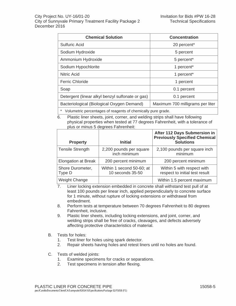
City Project No. UY-16/01-20 Invitation for Bids #PW 16-28City of Sunnyvale Primary Treatment Facility Package 2 Technical SpecificationsDecember 2016
PLASTIC LINER FOR CONCRETE PIPE 15058-5 pw://Carollo/Documents/Client/CA/Sunnyvale/9265A10/Specifications/Package 02/15058 (FS)
Chemical Solution ConcentrationSulfuric Acid 20 percent*
Sodium Hydroxide 5 percent
Ammonium Hydroxide 5 percent*
Sodium Hypochlorite 1 percent*
Nitric Acid 1 percent*
Ferric Chloride 1 percent
Soap 0.1 percent
Detergent (linear alkyl benzyl sulfonate or gas) 0.1 percent
Bacteriological (Biological Oxygen Demand) Maximum 700 milligrams per liter* Volumetric percentages of reagents of chemically pure grade.
6. Plastic liner sheets, joint, corner, and welding strips shall have following physical properties when tested at 77 degrees Fahrenheit, with a tolerance of plus or minus 5 degrees Fahrenheit:
Property Initial
After 112 Days Submersion in Previously Specified Chemical
SolutionsTensile Strength 2,200 pounds per square
inch minimum2,100 pounds per square inch
minimum
Elongation at Break 200 percent minimum 200 percent minimum
Shore Durometer, Type D
Within 1 second 50-60; at 10 seconds 35-50
Within 5 with respect with respect to initial test result
Weight Change Within 1.5 percent maximum7. Liner locking extension embedded in concrete shall withstand test pull of at
least 100 pounds per linear inch, applied perpendicularly to concrete surface for 1 minute, without rupture of locking extensions or withdrawal from embedment.
8. Perform tests at temperature between 70 degrees Fahrenheit to 80 degrees Fahrenheit, inclusive.
9. Plastic liner sheets, including locking extensions, and joint, corner, and welding strips shall be free of cracks, cleavages, and defects adversely affecting protective characteristics of material.
B. Tests for holes:1. Test liner for holes using spark detector.2. Repair sheets having holes and retest liners until no holes are found.
C. Tests of welded joints:1. Examine specimens for cracks or separations.2. Test specimens in tension after flexing.
City Project No. UY-16/01-20 Invitation for Bids #PW 16-28City of Sunnyvale Primary Treatment Facility Package 2 Technical SpecificationsDecember 2016
PLASTIC LINER FOR CONCRETE PIPE 15058-6 pw://Carollo/Documents/Client/CA/Sunnyvale/9265A10/Specifications/Package 02/15058 (FS)
3. Specimen shall withstand minimum load of 132 pounds per linear inch of weld, or product of 2,000 pounds per square inch times minimum thickness in inches of material adjoining weld, whichever is greater.
4. Thickness shall be taken within 2-inch gauge length.
PART 3 EXECUTION
3.01 INSTALLATION
A. Install liner in accordance with manufacturer's recommendations.
B. Install liner complete 360 angular degrees of pipe interior.
C. Do not nail through liner.
D. Install liner with liner anchors parallel with longitudinal axis of pipe.
E. Hold liner snugly in place against inner forms with light gauge steel wire, light steel banding straps, or other suitable means.
F. Set liner flush with inner edges of bells or grooved ends of pipe and extend to spigot or tongue end or to approximately 3 inches beyond tongue ends, depending upon the type of liner of the adjoining pipe.
G. Where lined pipe joins unlined pipe, such as brick structures, concrete pipe, cast-in-place structures, or clay pipe, extend enough liner to go over and around ends of pipe and back into the structure for a minimum of 4 inches.
H. Where unlined pipe spurs are installed through lined pipe, extend enough liner to return liner a minimum of 3 inches from surface of contact:1. Seal liner and spur with an acceptable adhesive.2. Where joint spaces are too wide or joint space surfaces too rough to allow
satisfactory sealing with adhesive, fill joint spaces with 2 inches of densely caulked lead wool or other accepted caulking material.
3.02 PLASTIC LINER REPAIRS
A. Patch liner defects in accordance with liner manufacturer's published instructions.
B. Patch small defects, such as nails, form tie holes, and small repairs and abraded areas, by fusing welding strips over defects to liner.
C. Patch larger defects by adhering smooth liner patches over defects, plus minimum 1-inch around defects, to liner with adhesive, centering welding strips over edges of patches, and fusing welding strips to liner and patches.
City Project No. UY-16/01-20 Invitation for Bids #PW 16-28City of Sunnyvale Primary Treatment Facility Package 2 Technical SpecificationsDecember 2016
PLASTIC LINER FOR CONCRETE PIPE 15058-7 pw://Carollo/Documents/Client/CA/Sunnyvale/9265A10/Specifications/Package 02/15058 (FS)
D. Cut out bubbles less than 2 inches in greatest dimension, adhere smooth liner patches over cut out areas plus minimum 1 inch around defects with adhesive, centering welding strips over edges of patches, and fusing welding strips to liner and patches:1. Reject pipe with larger bubbles.
3.03 CONCRETE OPERATIONS
A. Concrete placement:1. Carefully vibrate concrete placed against liner to avoid damage to liner and to
produce dense, homogeneous concrete securely anchoring locking extensions into concrete.
2. Use external vibrators in addition to internal vibrators, particularly along lower terminal edge of plastic liner.
B. Removing forms:1. In removing forms, protect liner from damage.2. Do not use sharp instruments to pry forms from lined surfaces.
3.04 FIELD JOINTING OF LINER
A. General:1. Make no field joint in liner until pipe has been backfilled and 30 days have
elapsed.2. Where groundwater is encountered, do not make joint until pumping of
groundwater has been discontinued for at least 30 days and no visible leakage is evident at joint.
3. Liner at joints shall be free of mortar and other foreign materials and shall be clean and dry before joints are made.
4. Do not bring hot joint compound in contact with liner.5. Do not apply coating over joints, corners, or welding strips.
B. Field joints in cast-in-place structures shall be one of following types:1. Type C-1:
a. Make joints with 4-inch joint strips, and secured along each edge to adjacent liner by welding strips.
b. Gaps between ends of lock extensions shall not exceed 4 inches.c. Width of spaces between adjacent sheets of liner shall not exceed
1/2 inch.d. Use joint at transverse contraction joints in concrete.
2. Type C-2:a. Make joints by overlapping sheets not less than 1-1/2 inches and securing
overlaps to adjacent liner with welding strips.b. Upstream sheet shall overlap downstream sheet.c. Length of overlapping sheet parts without locking extensions shall not
exceed 4 inches.d. Apply welding strips to back of joint.e. Use joint at longitudinal joints in concrete and transverse liner joints other
than at transverse contraction joints in concrete.
City Project No. UY-16/01-20 Invitation for Bids #PW 16-28City of Sunnyvale Primary Treatment Facility Package 2 Technical SpecificationsDecember 2016
PLASTIC LINER FOR CONCRETE PIPE 15058-8 pw://Carollo/Documents/Client/CA/Sunnyvale/9265A10/Specifications/Package 02/15058 (FS)
3. Type C-3:a. Make joints by putting sheets of liner together and applying welding strips
over back of joints before concrete is poured, and applying welding strips over front of joint, after concrete is poured.
b. Do not use this type of joint at transverse joints which extend to lower terminal edges of liner or at joints where gaps between adjoining sheets of liner exceed 1/8 inch.
C. Installation of welding strips:1. Contractor shall certify all welders. Qualifications of the welders shall be
submitted.2. Only certified welders shall preform fusion weld welding strips to joint strips
and liner. 3. Continuously weld joint in one operation until joint has been completed.4. At lower terminal edges of liner, extend each transverse welding strip at least
2 inches to provide tabs.5. Engineer may test each transverse weld by applying 10-pound pull to tab,
normal to face of structure.6. Hold liner adjoining welding strip in place during application of force.7. When weld failure develops, maintain 10-pound pull until no further separation
occurs.8. Defective welds will be retested after repairs have been made.9. Trim tabs away neatly after welding strip has passed test.
D. Joint reinforcement:1. Apply 12-inch long welding strips as reinforcement across transverse joints in
liner which extends to lower terminal edge of liner on each side structure.2. Center reinforcement strips over joint being reinforced, locating as close to
lower edge of liner as practicable.3. Weld reinforcement strips in place after transverse welding strips have been
tested and test tabs removed.
3.05 FIELD QUALITY CONTROL
A. The Contractor shall perform the required to test liner in accordance with manufacturer's published instructions and as follows.
B. The Contractor shall submit the results of all field tests.
C. Polyvinyl chloride liner pull test:1. Perform test on a minimum of 1 pipe section for each 400 feet of pipe
produced for the project.2. Perform test in a location within 2 feet of the end of the pipe that was up during
the manufacturing process.3. When one pipe section fails the liner pull test, test 2 other pipe sections from
the same manufacturing run as the failed section:a. If both additional pipe sections satisfactorily pass the pull test, the
remainder of the pipe in that manufacturing run will be accepted.
City Project No. UY-16/01-20 Invitation for Bids #PW 16-28City of Sunnyvale Primary Treatment Facility Package 2 Technical SpecificationsDecember 2016
PLASTIC LINER FOR CONCRETE PIPE 15058-9 pw://Carollo/Documents/Client/CA/Sunnyvale/9265A10/Specifications/Package 02/15058 (FS)
b. This acceptance is conditional upon satisfactory completion of the other pull tests specified under Polyvinyl Chloride Liner Pull Test.
c. If either of the additional pipe sections fail the pull test, the remainder of the pipe sections produced in that manufacturing run shall be subjected to the pull test.
D. After pipe installation, test surfaces of liner with electrical holiday detector with the instrument set at 15,000 volts.
E. Physically test welds by non-destructive probing.
F. Testing liner welds:1. Provide welding strips for testing liner welds:
a. Extended welding straps 2 inches below liner to form a tab.2. Apply a 10-pound pull normal to faces of pipe with spring balances.3. Hold liner adjoining welding strips against concrete during application of force.4. Maintain 10-pound pull where weld failures develop until further separation
does not occur.5. Repair defective welds then repeat test procedure.6. Test repaired welds until no longer defective.7. Trim tabs away neatly after successful testing of weld strips.
3.06 PROTECTION AND REPAIR
A. Take necessary measures and precautions to prevent damage to liner from equipment and materials used in, or taken through Work.
B. Repair damage to installed liner as follows:1. Patch nail and tie holes and cuts, tears, and abraded areas.2. Fuse patches made entirely with welding strip to liner over entire patch:
a. Limit use of this method to patches which can be made with single welding strip.
3. Do not use parallel, overlapping, or adjoining welding strips.4. Larger patches may consist of smooth liner over damaged area with edges
covered with welding strips fused to patch and to liner adjoining damaged area.
5. Limit width of single patch of latter type to 4 inches.
END OF SECTION

City Project No. UY-16/01-20 Invitation for Bids #PW 16-28City of Sunnyvale Primary Treatment Facility Package 2 Technical SpecificationsDecember 2016
PIPE SUPPORTS 15061-1 pw://Carollo/Documents/Client/CA/Sunnyvale/9265A10/Specifications/Package 02/15061 (FS)
SECTION 15061
PIPE SUPPORTS
PART 1 GENERAL
1.01 SUMMARY
A. Section includes: Supports for pipe, fittings, valves, and appurtenances.
B. Related sections: 1. The Contract Documents are complementary; what is called for by one is as
binding as if called for by all.2. It is the Contractor's responsibility for scheduling and coordinating the Work of
subcontractors, suppliers, and other individuals or entities performing or furnishing any of Contractor's Work.
3. The following Sections are related to the Work described in this Section. This list of Related Sections is provided for convenience only and is not intended to excuse or otherwise diminish the duty of the Contractor to see that the completed Work complies accurately with the Contract Documents: a. Section 01612 - Seismic Design Requirements.b. Section 05120 - Structural Steel.c. Section 05190 - Mechanical Anchoring and Fastening to Concrete and
Masonry.d. Section 09960 - High-Performance Coatings.e. Section 15052 - Common Work Results for General Piping. f. Section 15053 - Seismic Restraints for Piping.g. Section 15054 - Expansion Control for Piping.h. Section 15062 - Preformed Channel Pipe Support System.i. Section 15063 - Non-Metallic Pipe Support System.
1.02 REFERENCES
A. American National Standard Institute or Manufacturer's Standardization Society (ANSI/MSS): 1. SP-58 - Standard for Pipe Hangers and Supports - Materials, Design, and
Manufacture.2. SP-69 - Standard for Pipe Hangers and Supports - Selection and Application.
B. American Society for Testing Materials (ASTM):1. B 633 - Specification for Electrodeposited Coatings of Zinc on Iron and Steel.2. A 123 - Specification for Zinc (Hot-Galvanized) Coatings on Products
Fabricated from Rolled, Pressed, and Forged Steel Shapes, Plates, Bars andStrip.
3. A 653 - Specification for Steel Sheet, Zinc-Coated by the Hop-Dip Process.4. A 1011 - Specification for Steel, Sheet, Hot-Rolled, Carbon, Structural High-
Strength Low-Alloy, and High-Strength Low-Alloy with Improved Formability.
City Project No. UY-16/01-20 Invitation for Bids #PW 16-28City of Sunnyvale Primary Treatment Facility Package 2 Technical SpecificationsDecember 2016
PIPE SUPPORTS 15061-2 pw://Carollo/Documents/Client/CA/Sunnyvale/9265A10/Specifications/Package 02/15061 (FS)
C. National Fire Protection Association (NFPA): 1. NFPA 13 - Standard for the Installation of Sprinkler Systems.
1.03 SYSTEM DESCRIPTION
A. Contractor shall provide final design, inspection, and certification for supports, seismic restraints, and provisions for control of expansion for this project: 1. The design of these systems shall be the product of a qualified professional
engineer licensed to practice in the State of California retained by Contractor, (hereinafter and in all referenced sections the Design Professional).
2. The hanger and support design drawings and calculations shall be prepared and signed by the Design Professional and shall bear the Design Professional's registration seal.
3. The Design Professional shall obtain and maintain professional liability insurance in the amount of $1,000,000 per incident with a $1,000,000 aggregate to be in effect the project duration plus 1 year.
4. Design Professional shall have no less than 5 years of experience in type of piping work required for this project.
5. These requirements, however, shall not be construed as relieving Contractorof overall responsibility for this portion of the work.
B. In some cases, pipe supports and expansion controls are shown on the Drawings. In other cases, they are not shown, but are required. In general, seismic restraints are not shown, but are required. Contractor is responsible to supply complete pipe supports, seismic restraints, and expansion control systems whether they are shown on the Drawings or not.
1.04 DEFINITIONS
A. Buried pipe: Pipe that is buried in the soil, or cast in a concrete pipe encasement that is buried in the soil.
B. Exposed pipe: Pipe that is located above ground, or pipe that is located inside a structure, supported by a structure, or cast into a concrete structure.
C. Underground piping: Piping actually buried in soil or cast in concrete that is buried in soil.
D. Submerged piping: Piping below tops of walls in basins or tanks containing water.
E. Wet wall: Wall with water on at least 1 side.
1.05 DESIGN/PERFORMANCE REQUIREMENTS
A. The pipe system drawings shall show the hanger and support locations as well as the details of the seismic restraints and expansion control systems.
B. The pipe hanger and support system shall be coordinated with the seismic restraint specified under Section 15053 and the expansion control system specified under the provisions of Section 15054.
City Project No. UY-16/01-20 Invitation for Bids #PW 16-28City of Sunnyvale Primary Treatment Facility Package 2 Technical SpecificationsDecember 2016
PIPE SUPPORTS 15061-3 pw://Carollo/Documents/Client/CA/Sunnyvale/9265A10/Specifications/Package 02/15061 (FS)
C. Design supports to limit pipe deflection to L/240, and a spacing not to exceed 10 feet on center.
D. The Contractor shall coordinate the design of the hanger and support system with the design of the electrical support systems in Section 16070.
E. The Contactor shall coordinate the design for the hanger and support system with the of ductwork support systems.
F. The Contractor shall select pipe hangers and supports as specified in this Section and elsewhere in the Specifications or Drawings. Selections shall be based upon the pipe support classifications specified in MSS-SP69, the piping insulation thickness specified in Section 15082, and any special requirements that may be specified in other sections of the Specifications or Drawings.
G. The Contractor shall review the piping layout in the in relation to the surrounding structure and adjacent piping, ductwork, electrical support systems, and equipment before selecting the type of support to be used at each hanger point.
H. Where shown on the Drawings, supports are provided as guidance and may not meet minimum requirements. The Contractor shall provide, at no additional cost to the Owner, additional pipe supports as necessary and required by the Specifications. Supports shown on the Drawings shall be provided and shall be incorporated into the overall hanger and support system design.
I. Hangers and supports used in fire protection piping systems shall be listed and labeled by Underwriters Laboratories (UL).
1.06 SUBMITTALS
A. Design Professional Qualifications: 1. Education, proof of registration, and previous experience in performing this
type of work.2. Documentation shall be sufficient to demonstrate compliance with
requirements of this Section.
B. Calculations: 1. Calculations and other information to substantiate supports meet minimum
design strength requirements for following:a. Pipe/ductwork loads, seismic bracing and expansion control. b. Connections and anchors.
2. Seismic loads shall be as specified in Section 01612.3. Calculations shall be sealed by the Design Professional.
C. Product Data:1. Manufacturer's data sheets on each product used.2. As required by Section 05190.3. Preparation instructions and recommendations by Manufacturer.4. Storage and handling requirements.5. Installation methods.
City Project No. UY-16/01-20 Invitation for Bids #PW 16-28City of Sunnyvale Primary Treatment Facility Package 2 Technical SpecificationsDecember 2016
PIPE SUPPORTS 15061-4 pw://Carollo/Documents/Client/CA/Sunnyvale/9265A10/Specifications/Package 02/15061 (FS)
D. Shop Drawings:1. Include schedule, indicating where supports will be installed, where seismic
bracing will be installed, and drawings of pipe support system components and seismic bracing.
2. Piping and ductwork layout drawings, including supports, seismic restraints, and details of the expansion control systems.
3. Shop drawings shall be sealed by the Design Professional.
E. Inspection Reports: 1. Submit monthly inspection reports.
F. Final Inspection Report: 1. Submit final Inspection reports.
1.07 QUALITY ASSURANCE
A. The Design Professional shall inspect piping support installation, seismic restraints,and expansion control systems:1. Design Professional shall inspect the work at not more than monthly intervals
and submit inspection reports indicating progress of the work.2. Upon construction completion, but prior to beneficial occupancy of piping
systems by Owner, the Design Professional shall conduct a detailed final inspection and submit final report certifying all work is complete and in accordance with applicable requirements.
B. All reports shall bear Design Professional's registration seal and signature in accordance with the laws, rules, and regulations of the state.
PART 2 PRODUCTS
2.01 MATERIALS
A. Pipe Supports:1. Outdoor Areas: Areas exposed to natural outdoor environment or under
canopies: a. Stainless Steel Type 316.
2. Submerged locations, above water level inside water bearing structures and pipe supports for all stainless steel piping regardless of location: a. Stainless Steel Type 316.
3. Indoor Areas:a. Inside influent pump station dry pit and PST gallery: Hot-Dip Galvanized
Steel. Hot-dip galvanize pipe support after fabrication per ASTM A123.b. Inside utility tunnels (utilidors), service tunnels, pipe trenches: Stainless
Steel Type 316. c. All Other Indoor Areas: Stainless Steel Type 316.
City Project No. UY-16/01-20 Invitation for Bids #PW 16-28City of Sunnyvale Primary Treatment Facility Package 2 Technical SpecificationsDecember 2016
PIPE SUPPORTS 15061-5 pw://Carollo/Documents/Client/CA/Sunnyvale/9265A10/Specifications/Package 02/15061 (FS)
4. All stainless steel supports:a. Shop-fabricate. At the shop, perform pickling and passivation on all
surfaces inside and out.b. Field welding is prohibited unless specifically approved by the Owner. If
field welding is allowed, all field welds shall be passivated in the field.5. Plastic, Aluminum, FRP and Other Miscellaneous Materials: Use where
specifically indicated on the Drawings.
B. Concrete Anchors:1. As specified in Section 05190.
C. Fasteners:1. Stainless Steel Supports:
a. Type 316 stainless steel in accordance with ASTM A 193, Grade B8M for bolts and in accordance with ASTM A 194, Grade 8M for nuts.
2. Hot-Dip Galvanized Supports:a. Hot-dip galvanized ASTM A 307 steel, or ASTM A 36 meeting the
mechanical requirements of ASTM A 307.3. Plastic, Aluminum, FRP Supports:
a. Type 316 stainless steel in accordance with ASTM A 193, Grade B8M for bolts and in accordance with ASTM A 194, Grade 8M for nuts.
2.02 PIPE SUPPORTS
A. Concrete Inserts for Pipes under 30-inch Diameter: ANSI/MSS SP-69 Type 18.Minimum 1,140 pounds capacity with 5/8-inch diameter rod: 1. Manufacturers: One of the following or equal:
a. Anvil, Figure 282.b. Carpenter and Paterson, Figure CP-109.
B. Concrete Inserts for Pipe 30-inch Diameter and Larger: Hot-dip galvanized steel body with 3/4-inch diameter National Coarse zinc plated square nut, anchor insert tosteel concrete reinforcement:1. Manufacturers: One of the following or equal:
a. Connection Specialties, Inc., Model 6MD350.
C. Hanger Rods: Sized to match suspended pipe hanger, or as indicated on the Drawings: 1. Manufacturers: One of following or equal:
a. Anvil, Figure 140.b. Bergen-Paterson, Part 5000.c. B-Line Systems, Inc., Figure B3205.
D. Hanger Rods, Continuously Threaded: Sized to match suspended pipe hanger, or as indicated on the Drawings: 1. Manufacturers: One of the following or equal:
a. Anvil, Figure 146.b. Bergen-Paterson, Part BP-5006.
E. Eye Bolts: Welded and rated equal to full-load capacity of rod.

City Project No. UY-16/01-20 Invitation for Bids #PW 16-28City of Sunnyvale Primary Treatment Facility Package 2 Technical SpecificationsDecember 2016
PIPE SUPPORTS 15061-6 pw://Carollo/Documents/Client/CA/Sunnyvale/9265A10/Specifications/Package 02/15061 (FS)
F. Welded Eyebolt Rod:1. Manufacturers: One of the following or equal:
a. Anvil, Figure 278.b. Bergen-Paterson, Part 5004.c. B-Line Systems, Inc., Figure B3210.
G. Adjustable Ring Hangers: ANSI/MSS SP 69 Type 7: 1. Manufacturers: One of the following or equal:
a. Anvil.b. B-Line Systems, Inc., Figure B3172.
H. Adjustable Clevis Hangers: ANSI/MSS PS 69, Type 1: 1. Manufacturers: One of the following or equal:
a. Anvil, Figure 260.b. Bergen-Paterson, Part 6750.c. B-Line systems, Inc., Figure B3100 or B3105.
I. Adjustable Clevis Hangers for Insulated Pipe: Oversize: 1. Manufacturers: One of the following or equal:
a. Anvil, Figure 300.b. Bergen-Paterson, Part 6754.c. B-Line Systems, Inc. Figure B3108.
J. Brackets: ANSI/MSS SP-69 Type 32 with back plate; rated for 1,500 pounds:1. Manufacturers: One of the following or equal:
a. Anvil, Figure 195.b. B-Line Systems, Inc., Figure B3066.
K. Brackets, Heavy Duty: ANSI/MSS SP 69 Type 33 with back plate; rated for 3,000 pounds: 1. Manufacturers: One of the following or equal:
a. Anvil, Figure 199.b. B-Line Systems, Inc., Figure B3067.
L. Standard U-bolt: ANSI/MSS SP-69 Type 24: 1. Manufacturers: One of the following or equal:
a. Anvil, Figure 137.b. Bergen-Paterson, Part 6510.c. B-Line Systems, Inc., Figure B3188.
M. Riser Clamps: ANSI/MSS SP-69 Type 8: 1. Manufacturers: One of the following or equal:
a. Anvil, Figure 261.b. Bergen-Paterson, Part 6302.c. B-Line Systems, Inc., Figure B3373.
N. Pipe Clamps: ANSI/MSS SP 69 Type 4: 1. Manufacturers: One of the following or equal:
a. Anvil, Figure 212.
City Project No. UY-16/01-20 Invitation for Bids #PW 16-28City of Sunnyvale Primary Treatment Facility Package 2 Technical SpecificationsDecember 2016
PIPE SUPPORTS 15061-7 pw://Carollo/Documents/Client/CA/Sunnyvale/9265A10/Specifications/Package 02/15061 (FS)
b. Bergen-Paterson, Part 6100.c. B-Line Systems, Inc., Figure B3140.
O. Adjustable Offset Pipe Clamp:1. Manufacturers: One of the following or equal:
a. Anvil, Figure 100.b. B-Line Systems, Inc., Figure B3149.
P. Offset Pipe Clamp:1. Manufacturers: One of the following or equal:
a. Anvil, Figure 103.b. B-Line Systems, Inc., Figure B3148.
Q. Floor Stand or Stanchion Saddles: ANSI/MSS SP-69 Type 37. Provided with U-bolt hold down yokes: 1. Manufacturers: One of the following or equal:
a. Anvil, Figure 259.b. Bergen-Paterson, Part 6652.c. B-Line Systems, Inc., Figure B3090.
R. Spring Supports:1. Manufacturers: One of the following or equal:
a. Bergen-Paterson, Part 3200.b. Anvil, Figure B-268.
S. One Hole Pipe Clamps:1. Manufacturers: One of the following or equal:
a. Anvil, Figure 126.b. Carpenter and Paterson, Figure 237.
T. Welded Beam Attachment:1. Manufacturers: One of the following or equal:
a. Anvil, Figure 66.b. Bergen-Paterson, Part 1047.c. B-Line Systems, Inc., Figure B3083.
U. Heavy Pipe Clamp:1. Manufacturers: One of the following or equal:
a. Anvil, Figure 216.b. Bergen-Paterson, Part 6101.
V. Pipe Roll with Stand:1. Manufacturers: One of the following or equal:
a. Anvil, Figure 271.b. B-Line Systems, Inc., Figure B3117SL.
W. Anchor Bolts, Flush Shells, Powder Actuated Fasteners, and Concrete Anchors: As specified in Section 05120.
City Project No. UY-16/01-20 Invitation for Bids #PW 16-28City of Sunnyvale Primary Treatment Facility Package 2 Technical SpecificationsDecember 2016
PIPE SUPPORTS 15061-8 pw://Carollo/Documents/Client/CA/Sunnyvale/9265A10/Specifications/Package 02/15061 (FS)
PART 3 EXECUTION
3.01 INSTALLATION
A. Properly support, suspend, or anchor exposed pipe, fittings, valves, and appurtenances to prevent sagging, overstressing, or movement of piping; and to prevent thrusts or loads on or against connected pumps, blowers, and other equipment. Not all supports are shown on the Drawings. Provide supports shown in addition to the requirements herein.
B. Pipe supports shown on the Drawings do not show required seismic bracing. Provide seismic bracing as required.
C. Carefully determine locations of inserts. Anchor to formwork prior to placing concrete.
D. Use flush shells only where indicated on the Drawings.
E. Do not use anchors relying on deformation of lead alloy.
F. Do not use stud type powder actuated fasteners for securing steel pipe larger than 1 inch to concrete, masonry, or wood.
G. Suspend pipe hangers from hanger rods. Secured with double nuts.
H. Install continuously threaded hanger rods only where indicated on the Drawings.
I. Use adjustable ring hangers; or adjustable clevis hangers, for 6-inch and smaller diameter pipe.
J. Use adjustable clevis hangers for pipe larger than 6 inches in diameter.
K. Secure pipes with galvanized double-nutted U-bolts or suspend pipes from hanger rods and hangers.
L. Support Spacing:1. Support 2-inch and smaller piping on horizontal and vertical runs at maximum
5 feet on center, unless otherwise specified.2. Support larger than 2-inch piping on horizontal and vertical runs at maximum
10 feet on center, unless otherwise specified.3. Support exposed polyvinyl chloride and other plastic pipes at maximum 5 feet
on center, regardless of size.4. Support tubing, copper pipe and tubing, fiber-reinforced plastic pipe or duct,
and rubber hose and tubing at intervals close enough to prevent sagging greater than 1/4 inch between supports.
M. Install Supports at:1. Bends.2. Both sides of flexible pipe connections.3. Base of risers.
City Project No. UY-16/01-20 Invitation for Bids #PW 16-28City of Sunnyvale Primary Treatment Facility Package 2 Technical SpecificationsDecember 2016
PIPE SUPPORTS 15061-9 pw://Carollo/Documents/Client/CA/Sunnyvale/9265A10/Specifications/Package 02/15061 (FS)
4. Floor penetrations.5. Connections to pumps, blowers, and other equipment.6. Valves and appurtenances.
N. Securely anchor plastic pipe, valves, and headers to prevent movement during operation of valves.
O. Anchor plastic pipe between expansion loops and direction changes to prevent axial movement through anchors.
P. Provide ductile iron elbows or tees supported from floors with base fittings where indicated on the Drawings.
Q. Support base fittings with metal supports or when indicated on the Drawings,concrete piers.
R. Size hanger rods, supports, clamps, anchors, brackets, and guides in accordance with ANSI/MSS SP 58 and SP 69.
S. Do not use chains, plumbers' straps, wire, or similar devices for permanently suspending, supporting, or restraining pipes.
T. Support plumbing drainage and vents in accordance with Uniform Plumbing Code.
U. Supports, Clamps, Brackets, and Portions of Support System Bearing Against Copper Pipe: Copper-plated, copper throughout, or isolated with neoprene or polyvinyl chloride tape.
V. Where pipe is insulated, install oversized supports and hangers.
W. Install insulation shield in accordance with ANSI/MSS SP 69, Type 40. Shield shall be galvanized steel unless specified elsewhere.
X. Install riser clamps at floor penetrations and where indicated on the Drawings. 1. Paint or coat support system components as specified in Section 09960. Paint
pipe under the support system.
END OF SECTION

City Project No. UY-16/01-20 Invitation for Bids #PW 16-28City of Sunnyvale Primary Treatment Facility Package 2 Technical SpecificationsDecember 2016
PREFORMED CHANNEL PIPE SUPPORT SYSTEM 15062-1 pw://Carollo/Documents/Client/CA/Sunnyvale/9265A10/Specifications/Package 02/15062 (FS)
SECTION 15062
PREFORMED CHANNEL PIPE SUPPORT SYSTEM
PART 1 GENERAL
1.01 SUMMARY
A. Section includes: Preformed channel pipe support system consisting of preformed channels, fittings, straps, and fasteners engineered to support piping.
B. Hanger and support selection:1. The Contractor shall cause the pipe hangers and supports to be designed by
the Design Professional as required in 15061. 2. The pipe hanger and support system shall be coordinated with the seismic
restraint specified under Section 15053 and the expansion control system specified under the provisions of Section 15054.
C. Related sections:1. The Contract Documents are complementary; what is called for by one is as
binding as if called for by all. 2. It is the Contractor's responsibility for scheduling and coordinating the Work of
subcontractors, suppliers, and other individuals or entities performing or furnishing any of Contractor's Work.
3. The following Sections are related to the Work described in this Section. This list of Related Sections is provided for convenience only and is not intended to excuse or otherwise diminish the duty of the Contractor to see that the completed Work complies accurately with the Contract Documents: a. Section 05120 - Structural Steel.b. Section 09960 - High-Performance Coatings.c. Section 15052 - Common Work Results for General Piping. d. Section 15053 - Seismic Restraints for Piping.e. Section 15054 - Expansion Control for Piping.f. Section 15061 - Pipe Supports.
1.02 REFERENCES
A. American Institute of Steel Construction (AISC).
B. American Iron and Steel Institute (AISI).
C. American National Standard Institute/Manufacturer's Standardization Society (ANSI/MSS): 1. SP-58 - Pipe Hangers and Supports - Materials, Design, and Manufacture.2. SP-69 - Pipe Hangers and Supports - Selection and Application.
City Project No. UY-16/01-20 Invitation for Bids #PW 16-28City of Sunnyvale Primary Treatment Facility Package 2 Technical SpecificationsDecember 2016
PREFORMED CHANNEL PIPE SUPPORT SYSTEM 15062-2 pw://Carollo/Documents/Client/CA/Sunnyvale/9265A10/Specifications/Package 02/15062 (FS)
1.03 SYSTEM DESCRIPTION
A. Design criteria:1. Provide design of the support system per Section 15061.2. Include live, dead, and seismic loads associated with piping, valves, and
appurtenances. Consider the content of the pipes in load calculations.3. Minimum Gauge Thickness: 12 gauge.4. Allowable Stress of Channels:
a. Steel Channels: The lesser of 25,000 pounds per square inch, or 0.66 times yield stress of steel.
b. Stainless Steel Channels: 0.66 times the yield stress of the stainless steel alloy.
5. Maximum deflection: 1/240 of span.6. Allowable column loads: As recommended by manufacturer in published
instruction for column's unsupported height and "K" value for calculating effective column length of not less than 1.0.
7. Future loads:a. Support systems indicated on the Drawings may include spaces intended
to accommodate future pipes.b. Assume such spaces are occupied by 6-inch diameter ductile iron pipes.
Only the number of pipes that would physically fit into the space need be considered.
c. Include the weight of the pipe contents in determining future loads. Assume pipe contents are water.
8. Seismic design criteria: As specified in Sections 15053 and 15061 and as specified for mechanical equipment.
9. Spacing of supports: As required to comply with design requirements but not more than 5 feet.
B. Materials:1. Refer to Section 15061.
1.04 SUBMITTALS
A. As required by Sections 15052 and 15061.
1.05 QUALITY ASSURANCE
A. Provide inspection reports and certifications as required by Section 15061.
B. Design preformed channel pipe support system for loads in accordance with applicable provisions of:1. AISC Manual of Steel Construction.2. AISI Cold-Formed Steel Design Manual.
C. Product standards:1. Pipe Support Components: Conform to MSS SP-69.2. Pipe Support Materials: Conform to MSS SP-58.
City Project No. UY-16/01-20 Invitation for Bids #PW 16-28City of Sunnyvale Primary Treatment Facility Package 2 Technical SpecificationsDecember 2016
PREFORMED CHANNEL PIPE SUPPORT SYSTEM 15062-3 pw://Carollo/Documents/Client/CA/Sunnyvale/9265A10/Specifications/Package 02/15062 (FS)
PART 2 PRODUCTS
2.01 MANUFACTURERS
A. Fabricate preformed channel pipe support system using, as a minimum, parts specified below and meeting the requirements specified under Design Criteria: 1. Manufacturers: One of the following or equal:
a. Unistrut, Series P1000 or P1001; P5500 or P5501, as indicated on the Drawings.
b. Allied Support Systems, Power Strut, Figure PS-200 or PS-200 2TS; PS-150 or PS-150 2TS.
c. B-Line Systems, Inc., Channel Type B22 or B22A; B12, or B12A.
2.02 MATERIALS
A. Unless otherwise specified, restraints, including braces, pipe and structural attachments, shall match the pipe support material as specified in Section 15061.
B. Nuts, bolts, and washers shall match materials specified for the nuts, bolts, and washers in Section 15061.
2.03 ACCESSORIES
A. Preformed channel concrete inserts: Minimum 12 inches long.1. Manufacturers: One of the following or equal:
a. Unistrut, Series P-3200.b. Allied Support Systems, Figure 282.c. B-Line Systems, Series B32I.
B. 90-degree angle fittings:1. Manufacturers: One of the following or equal:
a. Unistrut, P1026.b. Allied Support Systems, Power Strut, P603.
C. Pipe straps:1. For pipes 8 inches in diameter and smaller: Use 2-piece universal strap with
slotted hex head screw and nut: a. Manufacturers: One of the following or equal:
1) Unistrut, Series P1109 through P1126.2) Allied Support Systems, PS1100.3) B-Line Systems, Inc., Series B2000.
2. For pipes greater than 8 inches in diameter: Unless different material is otherwise indicated on the Drawings or specified, use 1-piece, 1-inch wide by 1/8-inch, thick steel strap, hot-dip galvanized after fabrication.
3. For stainless steel pipes: Use type of strap required for the pipe sizes specified above, but use Type 304 stainless steel materials.
D. Touch-up paint galvanized surfaces:1. Manufacturers: One of the following or equal:
a. Galvinox, Galvo-Weld.
E. Touch-up paint for painted surfaces: Same formulation as factory paint.
City Project No. UY-16/01-20 Invitation for Bids #PW 16-28City of Sunnyvale Primary Treatment Facility Package 2 Technical SpecificationsDecember 2016
PREFORMED CHANNEL PIPE SUPPORT SYSTEM 15062-4 pw://Carollo/Documents/Client/CA/Sunnyvale/9265A10/Specifications/Package 02/15062 (FS)
2.04 FABRICATION
A. Hot-dip galvanize support system components after fabrication to required length and shape.
B. Do not galvanize or paint stainless steel components.
PART 3 EXECUTION
3.01 INSTALLATION
A. Properly support, suspend, or anchor exposed pipe, fittings, valves, and appurtenances to prevent sagging, overstressing, or movement of piping; and to prevent thrusts or loads on or against connected pumps, blowers, and other equipment. Not all supports are shown on the Drawings. Provide supports shown in addition to the requirements herein.
B. Pipe supports shown on the Drawings do not show required seismic bracing. Provide seismic bracing as required.
C. Carefully determine locations of inserts. Anchor to formwork prior to placing concrete.
D. Use flush shells only where indicated on the Drawings.
E. Do not use anchors relying on deformation of lead alloy.
F. Do not use stud type powder actuated fasteners for securing metallic conduit or steel pipe larger than 1 inch to concrete, masonry, or wood.
G. Suspend pipe hangers from hanger rods. Secured with double nuts.
H. Install continuously threaded hanger rods only where indicated on the Drawings.
I. Use adjustable ring hangers; or adjustable clevis hangers, for 6-inch and smaller diameter pipe.
J. Use adjustable clevis hangers for pipe larger than 6 inches in diameter.
K. Secure pipes with galvanized double-nutted U-bolts or suspend pipes from hanger rods and hangers.
3.02 Support spacing:1. Support 2-inch and smaller piping on horizontal and vertical runs at maximum
5 feet on center, unless otherwise specified.2. Support larger than 2-inch piping on horizontal and vertical runs at maximum
10 feet on center, unless otherwise specified.
City Project No. UY-16/01-20 Invitation for Bids #PW 16-28City of Sunnyvale Primary Treatment Facility Package 2 Technical SpecificationsDecember 2016
PREFORMED CHANNEL PIPE SUPPORT SYSTEM 15062-5 pw://Carollo/Documents/Client/CA/Sunnyvale/9265A10/Specifications/Package 02/15062 (FS)
3. Support exposed polyvinyl chloride and other plastic pipes at maximum 5 feeton center, regardless of size.
4. Support tubing, copper pipe and tubing, fiber-reinforced plastic pipe or duct, and rubber hose and tubing at intervals close enough to prevent sagging greater than 1/4 inch between supports.
B. Install supports at:1. Horizontal bends.2. Both sides of flexible pipe connections.3. Base of risers.4. Floor penetrations.5. Connections to pumps, blowers, and other equipment.6. Valves and appurtenances.
C. Securely anchor plastic pipe, valves, and headers to prevent movement during operation of valves.
D. Anchor plastic pipe between expansion loops and direction changes to prevent axial movement through anchors.
E. Provide ductile iron elbows or tees supported from floors with base fittings where indicated on the Drawings.
F. Support base fittings with metal supports or when indicated on the Drawings,concrete piers.
G. Size hanger rods, supports, clamps, anchors, brackets, and guides in accordance with ANSI/MSS SP 58 and SP 69.
H. Do not use chains, plumbers' straps, wire, or similar devices for permanently suspending, supporting, or restraining pipes.
I. Support plumbing drainage and vents in accordance with Uniform Plumbing Code.
J. Supports, clamps, brackets, and portions of support system bearing against copper pipe: Copper-plated, copper throughout, or isolated with neoprene or polyvinyl chloride tape.
K. Where pipe is insulated, install oversized supports and hangers.
L. Install insulation shield in accordance with ANSI/MSS SP 69, Type 40. Shield shall be galvanized steel unless specified elsewhere.
M. Install riser clamps at floor penetrations and where indicated on the Drawings.
N. Paint or coat support system components as specified in Section 09960.
3.03 INSTALLATION
A. As required by Section 15061.
END OF SECTION


City Project No. UY-16/01-20 Invitation for Bids #PW 16-28City of Sunnyvale Primary Treatment Facility Package 2 Technical SpecificationsDecember 2016
NON-METALLIC PIPE SUPPORT SYSTEM 15063-1 pw://Carollo/Documents/Client/CA/Sunnyvale/9265A10/Specifications/Package 02/15063 (FS)
SECTION 15063
NON-METALLIC PIPE SUPPORT SYSTEM
PART 1 GENERAL
1.01 SUMMARY
A. Section includes: Non-metallic pipe support system including the following:1. Channel framing, and components.2. Pipe clamps.3. Fittings.4. Fasteners.
B. Hanger and support selection:1. The Contractor shall cause the pipe hangers and supports to be designed by
the Design Professional as required in 15061.2. The pipe hanger and support system shall be coordinated with the seismic
restraint specified under Section 15053 and the expansion control system specified under the provisions of Section 15054.
C. Related sections:1. The Contract Documents are complementary; what is called for by one is as
binding as if called for by all. 2. It is the Contractor's responsibility for scheduling and coordinating the Work of
subcontractors, suppliers, and other individuals or entities performing or furnishing any of Contractor's Work.
3. The following Sections are related to the Work described in this Section. This list of Related Sections is provided for convenience only and is not intended to excuse or otherwise diminish the duty of the Contractor to see that the completed Work complies accurately with the Contract Documents: a. Section 05120 - Structural Steel.b. Section 09960 - High-Performance Coatings.c. Section 15050 - Common Work Results for Mechanical Equipment. d. Section 15052 - Common Work Results for General Piping. e. Section 15053 - Seismic Restraints for Piping.f. Section 15054 - Expansion Control for Piping.g. Section 15061 - Pipe Supports.
1.02 REFERENCES
A. American Society for Testing Materials (ASTM):1. E 84 - Test Method for Surface Burning Characteristics of Building Materials.
1.03 SYSTEM DESCRIPTION
A. Design requirements:1. Provide design of the support system per Section 15061.
City Project No. UY-16/01-20 Invitation for Bids #PW 16-28City of Sunnyvale Primary Treatment Facility Package 2 Technical SpecificationsDecember 2016
NON-METALLIC PIPE SUPPORT SYSTEM 15063-2 pw://Carollo/Documents/Client/CA/Sunnyvale/9265A10/Specifications/Package 02/15063 (FS)
2. Include live, dead, and seismic loads associated with piping, valves, and appurtenances. Consider the content of the pipes in load calculations.
3. Maximum allowable deflection: 1/240 of span.4. Allowable column loads: As recommended by manufacturer in published
instruction for column's unsupported height and "K" value for calculating effective column length of not less than 1.0.
5. Future loads:a. Support systems indicated on the Drawings may include spaces intended
to accommodate future pipes.b. Assume such spaces are occupied by 6-inch diameter ductile iron pipes.
Only the number of pipes that would physically fit into the space need be considered.
c. Include the weight of the pipe contents in determining future loads. Assume pipe contents are water.
6. Seismic design criteria: As specified in Section 15053 and 15061 and as specified for mechanical equipment.
7. Spacing of supports: As required to comply with design requirements but not more than 5 feet.
1.04 SUBMITTALS
A. As required by Sections 15052 and 15061.
1.05 QUALITY ASSURANCE
A. Provide inspection and certification reports as required by Section 15061.
B. Supply all materials from a single manufacturer with sole responsibility for the pipe support system.
C. The supplied system including pipe clamps shall be interchangeable with industry standard 1-5/8-inch steel and fiberglass channel framing systems.
1.06 DELIVERY, STORAGE, AND HANDLING
A. Comply with Section 15050.
PART 2 PRODUCTS
2.01 MANUFACTURERS
A. One of the following or equal:1. StrutTech, Redmond, Washington.2. Unistrut, Wayne, Michigan.
2.02 MATERIALS
A. Fiberglass resin: Corrosion-resistant premium-grade vinylester.
City Project No. UY-16/01-20 Invitation for Bids #PW 16-28City of Sunnyvale Primary Treatment Facility Package 2 Technical SpecificationsDecember 2016
NON-METALLIC PIPE SUPPORT SYSTEM 15063-3 pw://Carollo/Documents/Client/CA/Sunnyvale/9265A10/Specifications/Package 02/15063 (FS)
B. Injection molded components: Polyurethane thermoplastics.
C. Flame spread of fiberglass:1. Vinylester Fiberglass (Series VF): Class 1, ASTM E 84.2. Polyurethane: V-O UL 94V.
D. Physical properties of fiberglass:Physical Properties
of Fiberglass Longitudinal TransverseTensile Strength 37,500 psi 10,000 psiTensile Modules 3.0 X 10⁶ psi 1.0 X 10⁶ psiFlexural Strength 37,500 psi 14,000 psiFlexural Modules 2.0 X 10⁶ psi 1.0 X 10⁶ psiCompressive Strength 37,500 psi 20,000 psiShear Strength 6,000 psi 5,500 psiIzod Impact 30-foot psi 5-foot psi
E. Surface veil: Fiberglass channel shall have polyester surface veil over 100 percent of the surface to provide protection against degradation from ultraviolet light.
F. Touch-up resin:1. Manufacturers: One of the following or equal:
a. Krylon, 7006-Satin Polyurethane Clear Finish.
G. Concrete anchors: 1. As specified in Section 05120.
2.03 COMPONENTS
A. Channel framing:1. All channel framing shall be supplied with integral notches 1 inch on center.2. Locate notches on interior flange to prevent slippage of pipe clamps and
fittings after installation.
B. Pipe clamps:1. Adjustable type: Non-metallic and non-conductive.2. Fixed type:
a. Pipe clamps for pipe less than 6 inches in diameter shall be non-metallic and non-conductive.
b. Pipe clamps for pipe equal to and greater than 6 inches in diameter shall be fiberglass.
C. Channel fittings:1. Make fittings and post bases from glass-filled polyurethane or polyester.

City Project No. UY-16/01-20 Invitation for Bids #PW 16-28City of Sunnyvale Primary Treatment Facility Package 2 Technical SpecificationsDecember 2016
NON-METALLIC PIPE SUPPORT SYSTEM 15063-4 pw://Carollo/Documents/Client/CA/Sunnyvale/9265A10/Specifications/Package 02/15063 (FS)
D. Fasteners:1. Make fasteners from one of the following materials:
a. Glass-filled polyurethane.b. Vinylester fiberglass.
E. Concrete anchors:1. As specified in Section 05120.
PART 3 EXECUTION
3.01 INSTALLATION
A. Properly support, suspend, or anchor exposed pipe, fittings, valves, and appurtenances to prevent sagging, overstressing, or movement of piping; and to prevent thrusts or loads on or against connected pumps, blowers, and other equipment. Not all supports are shown on the Drawings. Provide supports shown in addition to the requirements herein.
B. Pipe supports shown on the Drawings do not show required seismic bracing. Provide seismic bracing as required.
C. Carefully determine locations of inserts. Anchor to formwork prior to placing concrete.
D. Use flush shells only where indicated on the Drawings.
E. Do not use anchors relying on deformation of lead alloy.
F. Do not use stud type powder actuated fasteners for securing metallic conduit or steel pipe larger than 1 inch to concrete, masonry, or wood.
G. Suspend pipe hangers from hanger rods. Secure with double nuts.
H. Install continuously threaded hanger rods only where indicated on the Drawings.
I. Use adjustable ring hangers; or adjustable clevis hangers, for 6-inch and smaller diameter pipe.
J. Use adjustable clevis hangers for pipe larger than 6 inches in diameter.
K. Secure pipes with galvanized double-nutted U-bolts or suspend pipes from hanger rods and hangers.
L. Support spacing:1. Support 2-inch and smaller piping on horizontal and vertical runs at maximum
5 feet on center, unless otherwise specified.2. Support larger than 2-inch piping on horizontal and vertical runs at maximum
10 feet on center, unless otherwise specified.
City Project No. UY-16/01-20 Invitation for Bids #PW 16-28City of Sunnyvale Primary Treatment Facility Package 2 Technical SpecificationsDecember 2016
NON-METALLIC PIPE SUPPORT SYSTEM 15063-5 pw://Carollo/Documents/Client/CA/Sunnyvale/9265A10/Specifications/Package 02/15063 (FS)
3. Support exposed polyvinyl chloride and other plastic pipes at maximum 5 feeton center, regardless of size.
4. Support tubing, copper pipe and tubing, fiber-reinforced plastic pipe or duct, and rubber hose and tubing at intervals close enough to prevent sagging greater than 1/4 inch between supports.
M. Install supports at:1. Horizontal bends.2. Both sides of flexible pipe connections.3. Base of risers.4. Floor penetrations.5. Connections to pumps, blowers, and other equipment.6. Valves and appurtenances.
N. Securely anchor plastic pipe, valves, and headers to prevent movement during operation of valves.
O. Anchor plastic pipe between expansion loops and direction changes to prevent axial movement through anchors.
P. Provide ductile iron elbows or tees supported from floors with base fittings where indicated on the Drawings.
Q. Support base fittings with metal supports or when indicated on the Drawings,concrete piers.
R. Size hanger rods, supports, clamps, anchors, brackets, and guides in accordance with ANSI/MSS SP 58 and SP 69.
S. Do not use chains, plumbers' straps, wire, or similar devices for permanently suspending, supporting, or restraining pipes.
T. Support plumbing drainage and vents in accordance with Uniform Plumbing Code.
U. Supports, clamps, brackets, and portions of support system bearing against copper pipe: Copper-plated, copper throughout, or isolated with neoprene or polyvinyl chloride tape.
V. Where pipe is insulated, install oversized supports and hangers.
W. Install insulation shield in accordance with ANSI/MSS SP 69, Type 40. Shield shall be galvanized steel unless specified elsewhere.
X. Install riser clamps at floor penetrations and where indicated on the Drawings.
Y. Paint or coat support system components as specified in Section 09960.
3.02 INSTALLATION
A. As required by Section 15061.
END OF SECTION

City Project No. UY-16/01-20 Invitation for Bids #PW 16-28City of Sunnyvale Primary Treatment Facility Package 2 Technical SpecificationsDecember 2016
POLYETHYLENE PIPE (HDPE) 15067-1 pw://Carollo/Documents/Client/CA/Sunnyvale/9265A10/Specifications/Package 02/15067 (FS)
SECTION 15067
PIPE: POLYETHYLENE (HDPE)
PART 1 GENERAL
1.01 SUMMARY
A. Section includes:1. Polyethylene pipe.
B. Related sections:1. The Contract Documents are complementary; what is called for by one is as
binding as if called for by all.2. It is the Contractor's responsibility for scheduling and coordinating the Work of
subcontractors, suppliers, and other individuals or entities performing or furnishing any of Contractor's Work.
3. The following Sections are related to the Work described in this Section. This list of Related Sections is provided for convenience only and is not intended to excuse or otherwise diminish the duty of the Contractor to see that the completed Work complies accurately with the Contract Documents.a. Section 01340 - Shop Drawings, Product Data and Samples.b. Section 15052 - Common Work Results for General Piping.
1.02 QUALITY ASSURANCE
A. Referenced Standards:1. ASTM International (ASTM):
a. A53, Standard Specification for Pipe, Steel, Black and Hot-Dipped, Zinc-Coated, Welded and Seamless.
b. A197, Standard Specification for Cupola Malleable Iron.c. D638, Standard Test Method for Tensile Properties of Plastics.d. D1248, Standard Specification for Polyethylene Plastics Extrusion
Materials for Wire and Cable. e. D1693, Standard Test Method for Environmental Stress-Cracking of
Ethylene Plastics.f. D2240, Standard Test Method for Rubber Property-Durometer Hardness.g. D2513, Standard Specification for Thermoplastic Gas Pressure Pipe,
Tubing, and Fittings.h. D2683, Standard Specification for Socket-Type Polyethylene Fittings for
Outside Diameter-Controlled Polyethylene Pipe and Tubing.i. D3261, Standard Specification for Butt Heat Fusion Polyethylene (PE)
Plastic Fittings for Polyethylene (PE) Plastic Pipe and Tubing.j. D3350, Standard Specification for Polyethylene Plastics Pipe and Fittings
Materials.k. F714, Standard Specification for Polyethylene (PE) Plastic Pipe (DR-PR)
Based on Outside Diameter.
City Project No. UY-16/01-20 Invitation for Bids #PW 16-28City of Sunnyvale Primary Treatment Facility Package 2 Technical SpecificationsDecember 2016
POLYETHYLENE PIPE (HDPE) 15067-2 pw://Carollo/Documents/Client/CA/Sunnyvale/9265A10/Specifications/Package 02/15067 (FS)
2. Society for Protective Coatings (SSPC):a. SP 3, Power Tool Cleaning.
1.03 SUBMITTALS
A. Shop Drawings:1. See Specification Section 01340 for requirements for the mechanics and
administration of the submittal process.2. Provide detailed layout drawings showing alignment of pipes, location of
valves, fittings, and appurtenances, types of joints, connections to structures, and thrust restraint system layouts, as applicable.
3. Manufacturer's installation instructions.4. Layout drawings.
B. Certifications:1. Installer certification.
C. Field quality control documents: 1. Test reports.
D. Quality control:1. Provide written verification and that personnel using butt-fusion equipment are
trained to the satisfaction of the pipe supplier. Provide personnel training certifications from the pipe manufacturer.
2. Furnish affidavit of compliance for all HDPE pipe and fittings confirming that all materials fully conform to the specification requirements.
3. The Contractor shall provide written verification that personnel using the fusion joining equipment are trained in the skills necessary for the correct joining of HDPE pipe to the satisfaction of the pipe supplier. Certification of the training shall be provided from the certified representative of the pipe manufacturer.
4. Provide Manufacturer's Certificate of Installation and Functionality Compliance as specified in Section 01756.
PART 2 PRODUCTS
2.01 GENERAL
A. The Contractor shall provide high density polyethylene pipe as specified. The pipe shall be made to diameter and tolerances in accordance with ASTM F714. All pipe shall be made from virgin grade material. The pipe shall be of the diameter and class shown or specified and shall be furnished complete with all fabricated fittings, and other appurtenances as necessary for a complete and functional system.
2.02 DESIGN REQUIREMENTS
A. See pipe schedule in specification Section 15052.
B. Furnish all fittings and other appurtenances as necessary to provide a complete stormwater bypass system.

City Project No. UY-16/01-20 Invitation for Bids #PW 16-28City of Sunnyvale Primary Treatment Facility Package 2 Technical SpecificationsDecember 2016
POLYETHYLENE PIPE (HDPE) 15067-3 pw://Carollo/Documents/Client/CA/Sunnyvale/9265A10/Specifications/Package 02/15067 (FS)
2.03 MATERIALS
A. Equipment:1. Only tools approved by the pipe manufacturer or the Engineer shall be used
for assembly of pipe fittings and service connections to ensure proper installation.
2. The heater plate used for pipe joining shall be equipped with suitable means, such as thermometers or pyrometers, to measure the temperature of plate surfaces and to ensure uniform heating.
B. High molecular weight, high density polyethylene pipe.
C. Plastic Pipe Institute listed material PE4710.
D. Minimum cell classification: 445474C per ASTM D3350.
E. Pipe and fittings to conform with ASTM F714 and ASTM D3261.
F. Homogeneous, virgin grade material.
G. No cracks, holes, or other defects.
H. Backing rings: 316 SST.
I. Fittings: Manufactured with the same pressure rating as the connecting pipes.
J. Gaskets: Provide gaskets at flanges in accordance with Section 15052.
PART 3 EXECUTION
3.01 IDENTIFICATION
A. Identify each length of pipe clearly at intervals of 5 feet or less.1. Include:
a. Manufacturer's name and trademark.b. Nominal size of pipe. c. Appurtenant information regarding polymer cell classification and critical
identifications regarding performance specifications. d. NSF approvals when applicable.
3.02 INSTALLATION
A. See Specification Section 15060.
B. General:1. Install pipe as indicated on Drawings.2. Contractor shall insure that kinking or excessive bend diameters of the pipe do
not occur during the installation process.3. Contractor shall insure that the pipe installed in the trench is firmly supported.
City Project No. UY-16/01-20 Invitation for Bids #PW 16-28City of Sunnyvale Primary Treatment Facility Package 2 Technical SpecificationsDecember 2016
POLYETHYLENE PIPE (HDPE) 15067-4 pw://Carollo/Documents/Client/CA/Sunnyvale/9265A10/Specifications/Package 02/15067 (FS)
4. Contractor shall cap all open pipe ends at the end of the work day.5. Contractor shall remove any cave-in portions of the trench prior to placing
sand bagging around the pipe.6. HDPE pipe and fittings shall be by the same manufacturer.
a. The minimum strength of the fittings shall not be less than that of the pipe.7. Remove cutting and threading burrs.
C. Joining procedures:1. Install data logger on the pipe joint fusion equipment and record data at each
joint to confirm joints fusion complies with manufacturer recommendations.Temperature and interface pressure to be recorded at a minimum.
2. HDPE pipe joints shall be fused on the surface prior to installation into the trench.a. Alternative methods of fusing shall be approved by the Engineer.b. PE pipe joints shall be butt fused.
3. Fusion joiner must be qualified by type of fusion and fuse pipe only as qualified.
4. Each joint must be visually inspected inside and outside for damage, dirt, moisture, or any other abnormalities prior to fusing.
5. All joint fusion shall be performed in strict accordance with the manufacturer'sspecifications.
6. All fusion equipment must be approved by the manufacturer and operated by qualified and certified operators.a. Cost for testing and certifying personnel shall be born by the Contractor.
7. Sections of polyethylene pipe may be joined into continuous lengths on the job site above ground or within the trench. The joining method shall be the butt fusion method and shall be performed in strict accordance with the pipe manufacturer's recommendations. Fusion equipment used in the joining procedure shall be capable of meeting all conditions recommended by the pipe manufacturer, including, but not limited to, fusion temperature, and alignmentand fusion pressure. Welds shall provide full penetration and a homogeneous material across the cross section of the weld.
8. Polyethylene pipe shall be joined by butt fusion welding conforming to ASTM D2657 and pipe manufacturer's criteria for the type of joining. Joint strength shall be equal to that of the adjacent pipe.
9. The inside and outside of pipe ends shall be cleaned with a cotton or non-synthetic cloth to remove dirt, water, grease, and other foreign materials. Thepipe ends shall be cut square and carefully aligned just prior to heating.
10. Fusion beads: a. Exterior and interior: Smooth, uniform in appearance not to exceed
manufacturer's recommendation, or 0.438 inch, whichever is less.11. All pipe, especially the ends, shall be carefully cleaned before the pipe is
joined. Whenever work ceases for any reason, the end of the pipe shall be closed with a watertight fitting, plug, or cover. The interior of the pipe shall be kept free from dirt, foreign material or debris as the work progresses and the pipe shall be cleaned after completion.
City Project No. UY-16/01-20 Invitation for Bids #PW 16-28City of Sunnyvale Primary Treatment Facility Package 2 Technical SpecificationsDecember 2016
POLYETHYLENE PIPE (HDPE) 15067-5 pw://Carollo/Documents/Client/CA/Sunnyvale/9265A10/Specifications/Package 02/15067 (FS)
3.03 HANDLING AND STORAGE
A. Exercise care during the unloading, handling and storage of all polyethylene pipe to ensure that the pipe is not cut, gouged, scored, or otherwise damaged.1. Any pipe segment with damage exceeding 10 percent of the wall thickness
shall be cut out and removed from the site at the Contractor's cost.
B. Heavy canvas or nylon slings of suitable strength shall be used for lifting and supporting materials. Do not use chains or cables.
C. The pipe shall be stored so that it is not deformed axially or circumferentially.1. After the unloading of pipe material ordered to the project site, and before
installation of the pipe, the Contractor shall inspect all pipe to verify its condition. A pipe inspection report shall be filed with and approved by the Engineer prior to installation.
D. Pipe and fittings shall not be stored on rocks or gravel, or other hard material that might damage the pipe.
E. HDPE pipe without an ultraviolet inhibitor shall not be stored uncovered outside.
F. Store all rubber gaskets or sleeves in a cool, well ventilated place, and do not expose to the direct rays of the sun. Do not allow contact with oils, fuels, petroleum, or solvents.
3.04 REPAIRS
A. Only new pipe free from defects shall be installed. Portions of broken pipe or short lengths may be used providing they are properly cut back and used as stubs, or short lengths required at structures for flexible joints.
B. Broken or leaking sections of pipe must be replaced. Repair clamps will not be approved.
END OF SECTION


City Project No. UY-16/01-20 Invitation for Bids #PW 16-28City of Sunnyvale Primary Treatment Facility Package 2 Technical SpecificationsDecember 2016
EQUIPMENT IDENTIFICATION 15075-1 pw://Carollo/Documents/Client/CA/Sunnyvale/9265A10/Specifications/Package 02/15075 (FS)
SECTION 15075
EQUIPMENT IDENTIFICATION
PART 1 GENERAL
1.01 SUMMARY
A. Section includes:1. Equipment nameplates.2. Special items.
B. Related sections:1. The Contract Documents are complementary; what is called for by one is as
binding as if called for by all.2. It is the Contractor's responsibility for scheduling and coordinating the Work of
subcontractors, suppliers, and other individuals or entities performing or furnishing any of Contractor's Work.
3. The following Sections are related to the Work described in this Section. This list of Related Sections is provided for convenience only and is not intended to excuse or otherwise diminish the duty of the Contractor to see that the completed Work complies accurately with the Contract Documents:a. Section 01340 - Shop Drawings, Product Data and Samples. b. Section 01756 - Commissioning and Process Start-Up.c. Section 09960 - High-Performance Coatings.
1.02 SUBMITTAL
A. Submit as specified in Section 01340.
B. Shop Drawings:1. Product data. 2. Installation instructions.
C. Provide Manufacturer's Certificate of Source Testing as specified in Section 01756.
D. Samples.
E. Submit following as specified in Section 01740: 1. Warranty.
1.03 QUALITY ASSURANCE
A. Regulatory requirements: Comply with Section 01060.

City Project No. UY-16/01-20 Invitation for Bids #PW 16-28City of Sunnyvale Primary Treatment Facility Package 2 Technical SpecificationsDecember 2016
EQUIPMENT IDENTIFICATION 15075-2 pw://Carollo/Documents/Client/CA/Sunnyvale/9265A10/Specifications/Package 02/15075 (FS)
PART 2 PRODUCTS
2.01 EQUIPMENT NAMEPLATES
A. Material and fabrication:1. Stainless steel sheet engraved or stamped with text, holes drilled, or punch for
fasteners.
B. Fasteners:1. Number 4 or larger oval head stainless steel screws or drive pins.
C. Text:1. Manufacturer's name, equipment model number and serial number,
identification tag number; and when appropriate, drive speed, motor horsepower with rated capacity, pump rated total dynamic head, and impeller size.
2.02 SPECIAL ITEMS
A. In addition, special coating of following items will be required:Item Color
Valve handwheels and levers Red
Hoist hooks and blocks Yellow and black stripes
Steel guard posts In accordance with standard details
B. Paint minimum 2 inches high numbers on or adjacent to accessible valves, pumps, flowmeters, and other items of equipment which are indicated on the Drawings or in Specifications by number.
PART 3 EXECUTION
3.01 EXAMINATION
A. Verify satisfactory conditions of substrate for applying identification.
3.02 PREPARATION
A. Prepare and coat surfaces of special items as specified in Section 09960.
B. Prepare surface in accordance with product manufacturer's instructions.
3.03 COMMISSIONING AND PROCESS START-UP REQUIREMENTS
A. As specified in Section 01756 and this Section.
END OF SECTION

City Project No. UY-16/01-20 Invitation for Bids #PW 16-28City of Sunnyvale Primary Treatment Facility Package 2 Technical SpecificationsDecember 2016
PIPE IDENTIFICATION 15076-1 pw://Carollo/Documents/Client/CA/Sunnyvale/9265A10/Specifications/Package 02/15076 (FS)
SECTION 15076
PIPE IDENTIFICATION
PART 1 GENERAL
1.01 SUMMARY
A. Section includes: Pipe identification including the following:1. Pipe identification by color and legend.2. Underground warning tape.3. Tracer wire.4. Witness markers.5. Valve identification.
B. Related sections:1. The Contract Documents are complementary; what is called for by one is as
binding as if called for by all.2. It is the Contractor's responsibility for scheduling and coordinating the Work of
subcontractors, suppliers, and other individuals or entities performing or furnishing any of Contractor's Work.
3. The following Sections are related to the Work described in this Section. This list of Related Sections is provided for convenience only and is not intended to excuse or otherwise diminish the duty of the Contractor to see that the completed Work complies accurately with the Contract Documents:a. Section 01340 - Shop Drawings, Product Data and Samples. b. Section 01730 - Operation and Maintenance Data. c. Section 09960 - High-Performance Coatings.d. Section 15052 - Common Work Results for General Piping.
1.02 REFERENCES
A. American Society of Mechanical Engineers (ASME):1. A13.1 - Scheme for the Identification of Piping Systems.
1.03 SUBMITTALS
A. Submit as specified in Section 01340.
B. Submit following:1. Product data.2. Samples.3. Manufacturer's installation instructions.4. Submit following as specified in Section 01730:
a. Operation and Maintenance Data.b. Warranty.
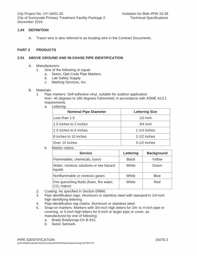
City Project No. UY-16/01-20 Invitation for Bids #PW 16-28City of Sunnyvale Primary Treatment Facility Package 2 Technical SpecificationsDecember 2016
PIPE IDENTIFICATION 15076-2 pw://Carollo/Documents/Client/CA/Sunnyvale/9265A10/Specifications/Package 02/15076 (FS)
1.04 DEFINITION
A. Tracer wire is also referred to as locating wire in the Contract Documents.
PART 2 PRODUCTS
2.01 ABOVE GROUND AND IN-CHASE PIPE IDENTIFICATION
A. Manufacturers:1. One of the following or equal:
a. Seton, Opti Code Pipe Markers.b. Lab Safety Supply.c. Marking Services, Inc.
B. Materials:1. Pipe markers: Self-adhesive vinyl, suitable for outdoor application
from -40 degrees to 180 degrees Fahrenheit; in accordance with ASME A13.1 requirements.a. Lettering:
Nominal Pipe Diameter Lettering SizeLess than 1.5 1/2 inch
1.5 inches to 2 inches 3/4 inch
2.5 inches to 6 inches 1-1/4 inches
8 inches to 10 inches 2-1/2 inches
Over 10 inches 3-1/2 inchesb. Marker colors:
Service Lettering BackgroundFlammables, chemicals, toxics Black Yellow
Water, nontoxic solutions or low hazard liquids
White Green
Nonflammable or nontoxic gases White Blue
Fire quenching fluids (foam, fire water, CO2 Halon)
White Red
2. Coating: As specified in Section 09960. 3. Pipe identification tags: Aluminum or stainless steel with stamped-in 1/4-inch
high identifying lettering.4. Pipe identification tag chains: Aluminum or stainless steel.5. Snap-on markers: Markers with 3/4-inch high letters for 3/4- to 4-inch pipe or
covering, or 5-inch high letters for 5-inch or larger pipe or cover, as manufactured by one of following:a. Brady Bradysnap-On B-915.b. Seton Setmark.
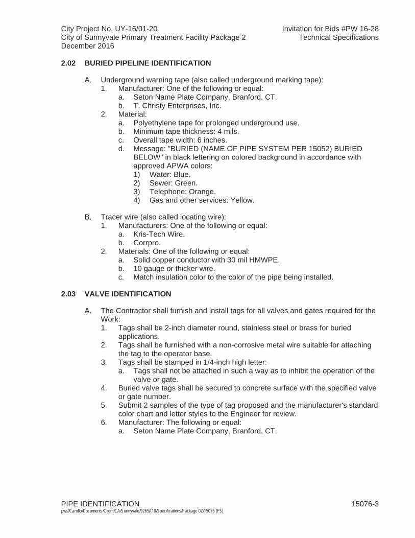
City Project No. UY-16/01-20 Invitation for Bids #PW 16-28City of Sunnyvale Primary Treatment Facility Package 2 Technical SpecificationsDecember 2016
PIPE IDENTIFICATION 15076-3 pw://Carollo/Documents/Client/CA/Sunnyvale/9265A10/Specifications/Package 02/15076 (FS)
2.02 BURIED PIPELINE IDENTIFICATION
A. Underground warning tape (also called underground marking tape): 1. Manufacturer: One of the following or equal:
a. Seton Name Plate Company, Branford, CT.b. T. Christy Enterprises, Inc.
2. Material:a. Polyethylene tape for prolonged underground use.b. Minimum tape thickness: 4 mils.c. Overall tape width: 6 inches.d. Message: "BURIED (NAME OF PIPE SYSTEM PER 15052) BURIED
BELOW" in black lettering on colored background in accordance with approved APWA colors:1) Water: Blue.2) Sewer: Green.3) Telephone: Orange.4) Gas and other services: Yellow.
B. Tracer wire (also called locating wire): 1. Manufacturers: One of the following or equal:
a. Kris-Tech Wire.b. Corrpro.
2. Materials: One of the following or equal:a. Solid copper conductor with 30 mil HMWPE.b. 10 gauge or thicker wire.c. Match insulation color to the color of the pipe being installed.
2.03 VALVE IDENTIFICATION
A. The Contractor shall furnish and install tags for all valves and gates required for the Work: 1. Tags shall be 2-inch diameter round, stainless steel or brass for buried
applications.2. Tags shall be furnished with a non-corrosive metal wire suitable for attaching
the tag to the operator base.3. Tags shall be stamped in 1/4-inch high letter:
a. Tags shall not be attached in such a way as to inhibit the operation of the valve or gate.
4. Buried valve tags shall be secured to concrete surface with the specified valve or gate number.
5. Submit 2 samples of the type of tag proposed and the manufacturer's standard color chart and letter styles to the Engineer for review.
6. Manufacturer: The following or equal:a. Seton Name Plate Company, Branford, CT.
City Project No. UY-16/01-20 Invitation for Bids #PW 16-28City of Sunnyvale Primary Treatment Facility Package 2 Technical SpecificationsDecember 2016
PIPE IDENTIFICATION 15076-4 pw://Carollo/Documents/Client/CA/Sunnyvale/9265A10/Specifications/Package 02/15076 (FS)
PART 3 EXECUTION
3.01 EXAMINATION
A. Verify satisfactory conditions of substrate for applying identification.
3.02 PREPARATION
A. Prepare and coat surfaces as specified in Section 09960.
B. Prepare surface in accordance with product manufacturer's instructions.
3.03 ABOVE GROUND AND IN-CHASE PIPING IDENTIFICATION
A. Identify exposed piping, valves, and accessories, in accessible chases with lettering or tags designating service of each piping system with flow directional arrows and color code.
B. Color code:1. Paint all piping with colors as scheduled in Piping Color Code and Marker
Schedule.
C. Lettering and flow direction arrows:1. Stencil lettering on painted bands or use snap-on markers on pipe to identify
pipe. When stenciling, stencil 3/4-inch high letters on 3/4- through 4-inch pipe or coverings, or 5-inch high letters on 5-inch and larger pipe or coverings.
2. Provide lettering and flow direction arrows near equipment served, adjacent to valves, both sides of walls and floors where pipe passes through, at each branch or tee, and at intervals of not more than 15 feet in straight runs of pipe.
3. Flow arrows shall be self-adhesive arrow roll tape such that flow arrows are visible from any orientation.
D. Where scheduled, space 6-inch wide bands along stainless steel pipe at 10-footintervals and other pipe at 5-foot intervals.
E. Label chemical tank fill pipelines at locations which are visible from chemical fill stations.
F. Metal tags:1. Where outside diameter of pipe or pipe covering is 5/8 inch or smaller, provide
metal pipe identification tags instead of lettering.2. Fasten pipe identification tags to pipe with chain.3. Where tags are used, color code pipe as scheduled.
3.04 BURIED PIPING IDENTIFICATION
A. Underground warning tape:1. All piping 2 inches and greater shall underground warning tape.2. Place continuous run of warning tape in pipe trench, 12 inches above the pipe.
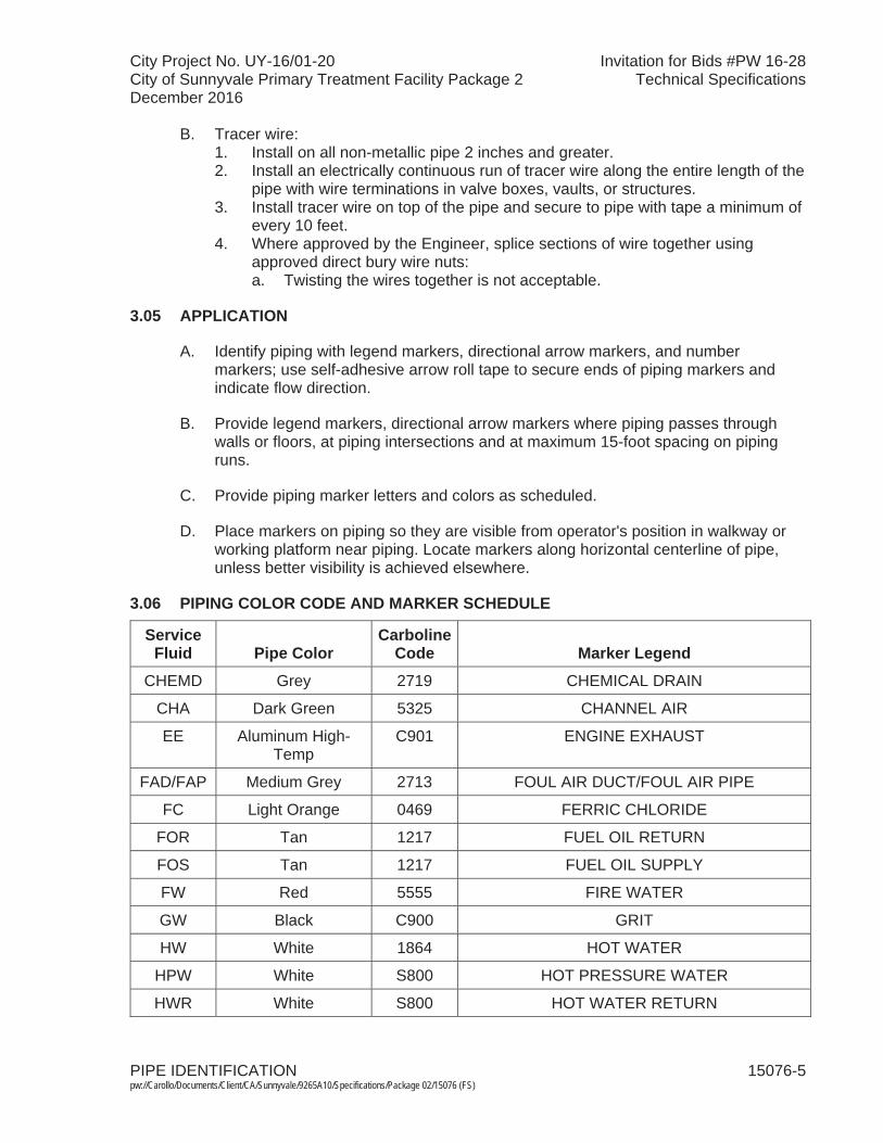
City Project No. UY-16/01-20 Invitation for Bids #PW 16-28City of Sunnyvale Primary Treatment Facility Package 2 Technical SpecificationsDecember 2016
PIPE IDENTIFICATION 15076-5 pw://Carollo/Documents/Client/CA/Sunnyvale/9265A10/Specifications/Package 02/15076 (FS)
B. Tracer wire:1. Install on all non-metallic pipe 2 inches and greater. 2. Install an electrically continuous run of tracer wire along the entire length of the
pipe with wire terminations in valve boxes, vaults, or structures.3. Install tracer wire on top of the pipe and secure to pipe with tape a minimum of
every 10 feet.4. Where approved by the Engineer, splice sections of wire together using
approved direct bury wire nuts:a. Twisting the wires together is not acceptable.
3.05 APPLICATION
A. Identify piping with legend markers, directional arrow markers, and number markers; use self-adhesive arrow roll tape to secure ends of piping markers and indicate flow direction.
B. Provide legend markers, directional arrow markers where piping passes through walls or floors, at piping intersections and at maximum 15-foot spacing on piping runs.
C. Provide piping marker letters and colors as scheduled.
D. Place markers on piping so they are visible from operator's position in walkway or working platform near piping. Locate markers along horizontal centerline of pipe, unless better visibility is achieved elsewhere.
3.06 PIPING COLOR CODE AND MARKER SCHEDULE
ServiceFluid Pipe Color
CarbolineCode Marker Legend
CHEMD Grey 2719 CHEMICAL DRAIN
CHA Dark Green 5325 CHANNEL AIR
EE Aluminum High-Temp
C901 ENGINE EXHAUST
FAD/FAP Medium Grey 2713 FOUL AIR DUCT/FOUL AIR PIPE
FC Light Orange 0469 FERRIC CHLORIDE
FOR Tan 1217 FUEL OIL RETURN
FOS Tan 1217 FUEL OIL SUPPLY
FW Red 5555 FIRE WATER
GW Black C900 GRIT
HW White 1864 HOT WATER
HPW White S800 HOT PRESSURE WATER
HWR White S800 HOT WATER RETURN
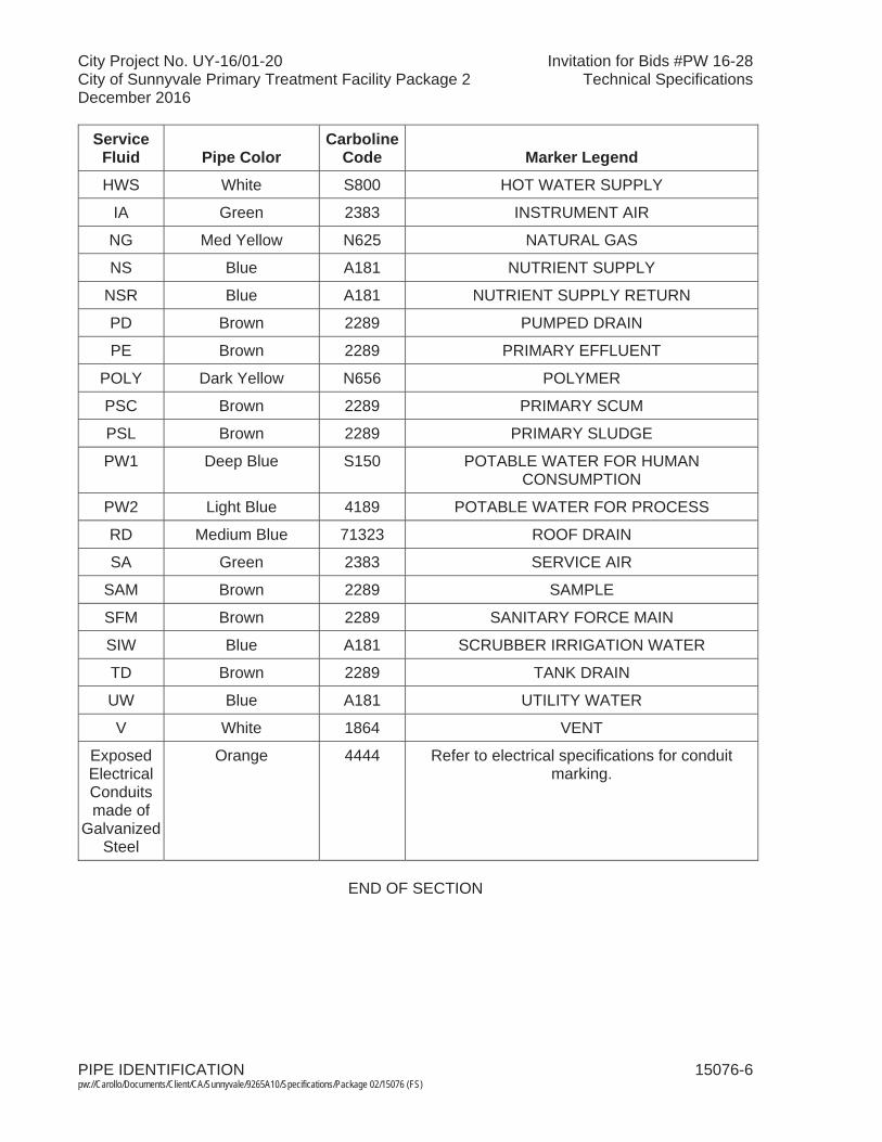
City Project No. UY-16/01-20 Invitation for Bids #PW 16-28City of Sunnyvale Primary Treatment Facility Package 2 Technical SpecificationsDecember 2016
PIPE IDENTIFICATION 15076-6 pw://Carollo/Documents/Client/CA/Sunnyvale/9265A10/Specifications/Package 02/15076 (FS)
ServiceFluid Pipe Color
CarbolineCode Marker Legend
HWS White S800 HOT WATER SUPPLY
IA Green 2383 INSTRUMENT AIR
NG Med Yellow N625 NATURAL GAS
NS Blue A181 NUTRIENT SUPPLY
NSR Blue A181 NUTRIENT SUPPLY RETURN
PD Brown 2289 PUMPED DRAIN
PE Brown 2289 PRIMARY EFFLUENT
POLY Dark Yellow N656 POLYMER
PSC Brown 2289 PRIMARY SCUM
PSL Brown 2289 PRIMARY SLUDGE
PW1 Deep Blue S150 POTABLE WATER FOR HUMAN CONSUMPTION
PW2 Light Blue 4189 POTABLE WATER FOR PROCESS
RD Medium Blue 71323 ROOF DRAIN
SA Green 2383 SERVICE AIR
SAM Brown 2289 SAMPLE
SFM Brown 2289 SANITARY FORCE MAIN
SIW Blue A181 SCRUBBER IRRIGATION WATER
TD Brown 2289 TANK DRAIN
UW Blue A181 UTILITY WATER
V White 1864 VENT
Exposed Electrical Conduitsmade of
Galvanized Steel
Orange 4444 Refer to electrical specifications for conduit marking.
END OF SECTION
City Project No. UY-16/01-20 Invitation for Bids #PW 16-28City of Sunnyvale Primary Treatment Facility Package 2 Technical SpecificationsDecember 2016
PIPING INSULATION 15082-1 pw://Carollo/Documents/Client/CA/Sunnyvale/9265A10/Specifications/Package 02/15082 (FS)
SECTION 15082
PIPING INSULATION
PART 1 GENERAL
1.01 SUMMARY
A. Section includes: Insulation for piping and related systems.
B. Related sections:1. The Contract Documents are complementary; what is called for by one is as
binding as if called for by all.2. It is the Contractor's responsibility for scheduling and coordinating the Work of
subcontractors, suppliers, and other individuals or entities performing or furnishing any of Contractor's Work.
3. The following Sections are related to the Work described in this Section. This list of Related Sections is provided for convenience only and is not intended to excuse or otherwise diminish the duty of the Contractor to see that the completed Work complies accurately with the Contract Documents: a. Section 01756 - Commissioning and Process Start-Up.b. Section 09960 - High-Performance Coatings.c. Section 15052 - Common Work Results for General Piping. d. Section 15076 - Pipe Identification.e. Section 15270 - Steel Pipe: Galvanized and Black; ASTM A53.f. Section 15286 - Stainless Steel Pipe and Tubing.
1.02 REFERENCES
A. ASTM International (ASTM):1. A 53 - Standard Specification for Pipe, Steel, Black, and Hot-Dipped,
Zinc-Coated, Welded, and Seamless.2. C 177 - Standard Test Method for Steady-State Heat Flux Measurements and
Thermal Transmission Properties by Means of the Guarded-Hot-Plate Apparatus.
3. C 518 - Standard Test Method for Steady-State Thermal Transmission Properties by Means of the Heat Flow Meter Apparatus.
4. C 533 - Standard Specification for Calcium Silicate Block and Pipe Thermal Insulation.
5. C 547 - Standard Specification for Mineral Fiber Pipe Insulation.6. C 552 - Standard Specification for Cellular Glass Thermal Insulation.7. C 795 - Standard Specification for Thermal Insulation for Use in Contact with
Austenitic Stainless Steel.8. C 929 - Standard Practice for Handling, Transporting, Shipping, Storage,
Receiving, and Application of Thermal Insulation Materials for Use in Contact with Austenitic Stainless Steel.
9. C 1136 - Standard Specification for Flexible, Low Permeance Vapor Retarders for Thermal Insulation.

City Project No. UY-16/01-20 Invitation for Bids #PW 16-28City of Sunnyvale Primary Treatment Facility Package 2 Technical SpecificationsDecember 2016
PIPING INSULATION 15082-2 pw://Carollo/Documents/Client/CA/Sunnyvale/9265A10/Specifications/Package 02/15082 (FS)
10. D 1784 - Standard Specification for Rigid Poly(Vinyl Chloride) (PVC) Compounds and Chlorinated Poly (Vinyl Chloride) (CPVC) Compounds.
11. D 2310 - Standard Classification of Machine-Made "Fiberglass"(Glass-Fiber-Reinforced-Thermosetting-Resin) Pipe.
12. E 84 - Standard Test Method for Surface Burning Characteristics of Building Materials.
13. E 96 - Standard Test Methods for Water Vapor Transmission of Materials.
1.03 DEFINITIONS
A. Buried: Piping that is installed below buildings, foundations, or finish grade, either in soil or encased in concrete in soil.
B. Concealed: Piping above suspended ceilings and within walls, partitions, shafts, or service spaces and spaces not normally exposed to view but not buried.
C. Exterior: Piping that is installed under canopies, outside a building, or within a pipe trench or tunnel.
D. Flame spread and smoke density: Burning characteristics determined in accordance with ASTM E 84. No units apply to value.
E. Interior: Piping that is installed inside a building.
F. K factor: Thermal conductivity determined in accordance with ASTM C 177 or C 518and expressed in units of BTU-inch/hour-square feet -degrees Fahrenheit.
G. Mineral fiber: Fibers manufactured of glass, rock, or slag processed from a molten state, with or without a binder.
H. Water vapor permeance: Water vapor transmission determined in accordance with ASTM E 96 and expressed in units of perm-inch.
1.04 SUBMITTALS
A. Product data:1. Insulation properties: Include K factor, thickness, density, operating
temperature limits, tensile strength, compressive strength, moisture absorption, flame spread, and smoke developed in accordance with ASTM E 84 and corrosivity to stainless steel piping in accordance with ASTM C 795.
2. Jacket properties: Include covering material, cover thickness, tensile strength, tear strength, permeability in accordance with ASTM E 96, flame spread, and smoke developed in accordance with ASTM E 84, closure type or devices, and accessories.
3. Insulating blankets: Include materials, performance characteristics, method of attaching to equipment, listing of locations where insulating blankets will be installed.
City Project No. UY-16/01-20 Invitation for Bids #PW 16-28City of Sunnyvale Primary Treatment Facility Package 2 Technical SpecificationsDecember 2016
PIPING INSULATION 15082-3 pw://Carollo/Documents/Client/CA/Sunnyvale/9265A10/Specifications/Package 02/15082 (FS)
B. Manufacturer's application instructions: Include assembly and application drawings and detailed instructions.
C. Laboratory report: Provide certified laboratory report stating that insulation is not manufactured using chlorinated polymers and does not contain chlorides, bromides, sulfates, or fire-rated materials.
D. Provide Manufacturer's Certificate of Source Testing as specified in Section 01756.
E. Provide Manufacturer's Certificate of Installation and Functionality Compliance as specified in Section 01756.
1.05 REGULATORY REQUIREMENTS
A. Projects located in California comply with California Energy Commission Energy Efficiency Standards for Residential and Non-Residential Buildings.
1.06 DELIVERY, STORAGE, AND HANDLING
A. Store insulation materials and accessories under cover and protected from moisture.
B. Handle and store insulation for use on stainless steel in accordance with ASTM C 929.
1.07 SEQUENCING AND SCHEDULING
A. Pressure test piping and complete application of coating system before applying insulation.
B. When piping is to be heat traced, install and functionally test heat tracing before installation of insulation.
C. Before beginning installation of piping insulation, verify that the Engineer has accepted piping tests, pipe coating applications, and heat tracing tests.
PART 2 PRODUCTS
2.01 PIPE INSULATION, GENERAL REQUIREMENTS
A. Insulation thicknesses: Provide insulation thickness in inches in accordance with the following table. Insulation thickness shown is nominal. Manufacturing tolerance of 15 percent variation is permissible:
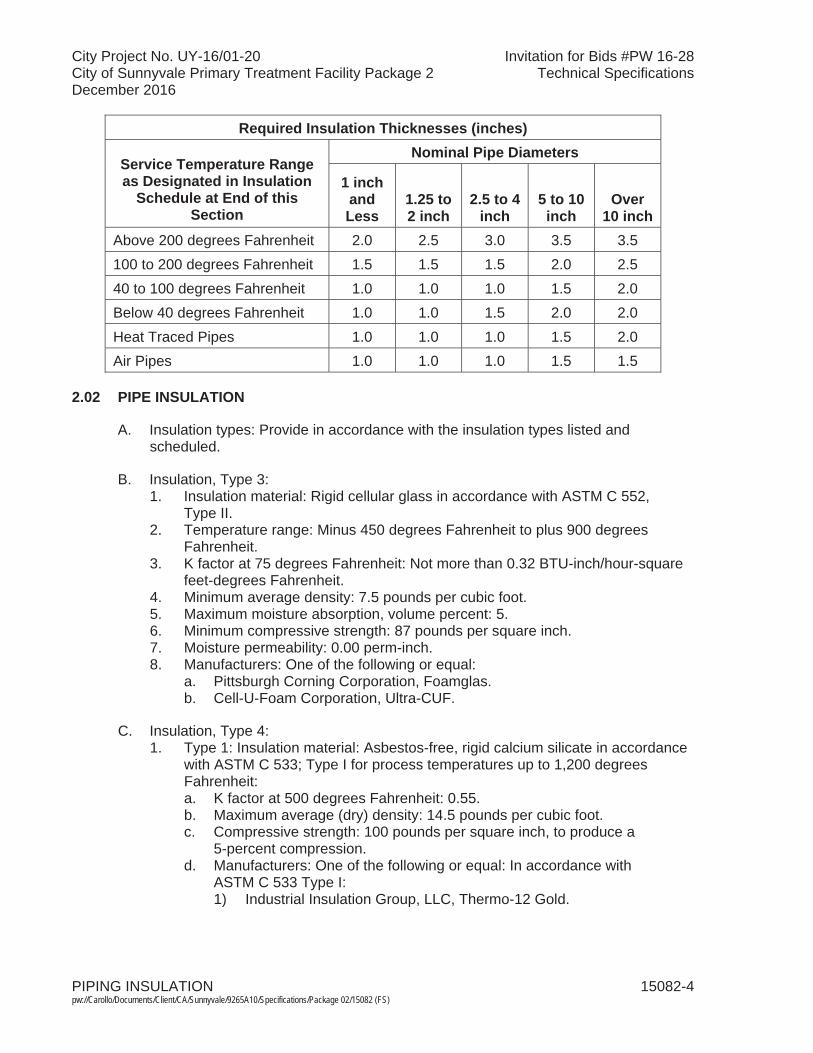
City Project No. UY-16/01-20 Invitation for Bids #PW 16-28City of Sunnyvale Primary Treatment Facility Package 2 Technical SpecificationsDecember 2016
PIPING INSULATION 15082-4 pw://Carollo/Documents/Client/CA/Sunnyvale/9265A10/Specifications/Package 02/15082 (FS)
Required Insulation Thicknesses (inches)
Service Temperature Range as Designated in Insulation
Schedule at End of this Section
Nominal Pipe Diameters
1 inch andLess
1.25 to 2 inch
2.5 to 4 inch
5 to 10 inch
Over 10 inch
Above 200 degrees Fahrenheit 2.0 2.5 3.0 3.5 3.5100 to 200 degrees Fahrenheit 1.5 1.5 1.5 2.0 2.540 to 100 degrees Fahrenheit 1.0 1.0 1.0 1.5 2.0Below 40 degrees Fahrenheit 1.0 1.0 1.5 2.0 2.0Heat Traced Pipes 1.0 1.0 1.0 1.5 2.0Air Pipes 1.0 1.0 1.0 1.5 1.5
2.02 PIPE INSULATION
A. Insulation types: Provide in accordance with the insulation types listed and scheduled.
B. Insulation, Type 3:1. Insulation material: Rigid cellular glass in accordance with ASTM C 552,
Type II.2. Temperature range: Minus 450 degrees Fahrenheit to plus 900 degrees
Fahrenheit.3. K factor at 75 degrees Fahrenheit: Not more than 0.32 BTU-inch/hour-square
feet-degrees Fahrenheit. 4. Minimum average density: 7.5 pounds per cubic foot.5. Maximum moisture absorption, volume percent: 5. 6. Minimum compressive strength: 87 pounds per square inch.7. Moisture permeability: 0.00 perm-inch.8. Manufacturers: One of the following or equal:
a. Pittsburgh Corning Corporation, Foamglas.b. Cell-U-Foam Corporation, Ultra-CUF.
C. Insulation, Type 4:1. Type 1: Insulation material: Asbestos-free, rigid calcium silicate in accordance
with ASTM C 533; Type I for process temperatures up to 1,200 degrees Fahrenheit: a. K factor at 500 degrees Fahrenheit: 0.55.b. Maximum average (dry) density: 14.5 pounds per cubic foot.c. Compressive strength: 100 pounds per square inch, to produce a
5-percent compression.d. Manufacturers: One of the following or equal: In accordance with
ASTM C 533 Type I:1) Industrial Insulation Group, LLC, Thermo-12 Gold.
City Project No. UY-16/01-20 Invitation for Bids #PW 16-28City of Sunnyvale Primary Treatment Facility Package 2 Technical SpecificationsDecember 2016
PIPING INSULATION 15082-5 pw://Carollo/Documents/Client/CA/Sunnyvale/9265A10/Specifications/Package 02/15082 (FS)
2. Type II: Insulation material: Asbestos free, rigid calcium silicate in accordance with ASTM C 533; Type II for process temperatures above 1,200 degrees Fahrenheit: a. K factor at 800 degrees Fahrenheit: 0.73. b. Maximum average (dry) density: 18 pounds per cubic foot.c. Compressive strength: 450 pounds per square inch, to produce a
5-percent compression.d. Manufacturers: One of the following or equal: In accordance with
ASTM C 533 Type II:1) Super Caltemp Gold 1700.
D. Insulation, Type 5, pre-insulated welded steel and stainless steel piping:1. Service pipe: 20 to 40 foot lengths, welded steel, flanged at equipment and
valves; as specified in Section 15052 and 15270 or 15286 for service.2. Insulation: Factory applied polyurethane foam; K factor of 0.16 at 73 degrees
Fahrenheit, average density of 1.8 to 2.0 pounds per cubic foot, suitable for service temperatures up to 250 degrees Fahrenheit.
3. Insulation cover: Fiberglass; multidirectional, filament-wound fiberglass reinforced polyester resin; minimum 0.125 inch wall thickness for service pipes up to 6 inches diameter, minimum 0.188 inch wall thickness for service pipes above 6 inches diameter.
4. Field joints: Provide prefabricated filings to minimize field joints. Where field are required; foamed with same insulation material; hand lay-up fiberglass cover bonded to adjoining cover.
5. Thermal expansion joints: Provide design and materials for expansion loops, expansion ells, and other fittings as required to accommodate service pipethermal expansion and contraction based on ambient and operating conditions specified in Section 15054 or as indicated on the Drawings; if not otherwise specified, design for 40 degrees Fahrenheit ambient and up to 250 degrees Fahrenheit service temperature.
6. Manufacturers: One of the following or equal:a. Perma-Pipe subsidiary of MFRI, Inc.b. Thermal Pipe Systems, Inc.; equivalent product.
2.03 INSULATION JACKETS
A. Jacket, Type 1:1. Material: 28 ounces per square yard polyvinyl chloride on polyester fabric; total
thickness 0.028 inches minimum.2. Fire rating: 25 maximum flame spread, smoke developed 50 or less.3. Color: As selected by the Engineer from manufacturer's standard colors.4. Overlap: 1-inch minimum at joints and fittings.5. Joint seal: Self-sealing lap tape.6. Fittings: Factory made with full thickness insulation.7. Manufacturers: One of the following or equal:
a. Accessible Products, Techlite Insulation, 379 SSL Series.
B. Jacket, Type 2:1. Material: Ultraviolet-resistant polyvinyl chloride jacketing, 20 mil minimum
thickness.
City Project No. UY-16/01-20 Invitation for Bids #PW 16-28City of Sunnyvale Primary Treatment Facility Package 2 Technical SpecificationsDecember 2016
PIPING INSULATION 15082-6 pw://Carollo/Documents/Client/CA/Sunnyvale/9265A10/Specifications/Package 02/15082 (FS)
2. Fire rating: 25 maximum flame spread, smoke developed 50 or less.3. Color: White.4. Overlap: 1-inch minimum at joints and fittings.5. Joint seal: PVC solvent welded or adhesive as recommended by the
manufacturer.6. Fittings: Factory made with full thickness insulation.7. Manufacturers: One of the following or equal:
a. Johns Manville, Zeston 2000 PVC.b. Proto Corp., LoSMOKE PVC.c. Speedline Smoke Safe PVC Jacketing System.d. Knauf Covering System.
C. Jacket, Type 3:1. Material: Aluminum, Alloy 5005; 0.016-inch (26 gauge) minimum thickness.2. Overlap: Overlap circumferential joints 4 inches minimum; overlap longitudinal
joints 1-inch minimum; longitudinal joints oriented to minimize water entry.3. Bands: 0.5 inch wide, 0.0508 inch (16 gauge) thick aluminum, same alloy as
jacket or 0.0179 inch thick Type 304 stainless steel; install on 18-inch centers, uniformly spaced and at all fitting joints.
4. Joint seal: Apply waterproof adhesive at joints and overlaps.5. Fittings: Custom fit of same materials.6. Manufacturers: One of the following or equal:
a. Childers Products.b. Premetco International.
2.04 VAPOR BARRIERS
A. Vapor barrier, Type 1:1. Material: White kraft paper bound to aluminum foil in accordance with
ASTM C 1136, Type 1.2. Permeability: 0.02 perms or lower.3. Maximum flame spread rating: 25.4. Edge seal: Pressure-sensitive tape lap seal.5. Circumferential joints: 4-inch wide tape or 4-inch overlap with adhesive seal.
B. Vapor barrier, Type 2:1. Material: Mastic.2. Manufacturers: One of the following or equal:
a. Benjamin Foster, No. 30-76.b. Insul-Coustic, No. I.C.-580.c. Foster Products, 36-10/46-10 Weatherite.d. Childers Products CP10/11 Vi-Acryl.
2.05 RELATED MATERIALS
A. Cover adhesive: Premium adhesive as recommended by the insulation cover supplier for heavy-duty service in corrosive, wet environments. Standard-duty adhesives are not permitted.

City Project No. UY-16/01-20 Invitation for Bids #PW 16-28City of Sunnyvale Primary Treatment Facility Package 2 Technical SpecificationsDecember 2016
PIPING INSULATION 15082-7 pw://Carollo/Documents/Client/CA/Sunnyvale/9265A10/Specifications/Package 02/15082 (FS)
2.06 REMOVABLE INSULATING BLANKETS
A. In piping systems specified to be insulated, use removable insulating blankets for valves, meters, strainers, filters, catalytic converters, engine exhaust silencers, and other in-line piping appurtenances and equipment requiring periodic servicing.
B. Size limits: Use removable insulating blankets for equipment and piping appurtenances 3-inch in nominal size and larger. Insulate equipment and piping appurtenances less than 3-inch with molded sections of insulation or by field cutting insulation to conform to the shape of the component and to fit tightly around the component.
C. Manufacturers: One of the following, or equal:1. Pittsburgh Corning, Temp-Mat.2. Accessible Products, Thermazip 2000 Jacket.3. Thermal Energy Products, Inc., Energy Wrap.
D. Low temperature insulating blankets rated up to 800 degrees Fahrenheit:1. Use: For service temperatures up to 800 degrees Fahrenheit.2. Insulation: Fiberglass fiber, K factor 0.27 at 75 degrees Fahrenheit.3. Cover: 17-ounce fabric with both sides covered with silicone-impregnated
glass cloth suitable for temperatures up to 800 degrees Fahrenheit.4. Cover fasteners: Use one of the following systems:
a. Grommets in the blanket and stainless steel wire. b. 1-inch wide straps with stainless steel rectangular ring buckles and Velcro
on strap tail.
E. High temperature insulating blankets rated up to 1,400 degrees Fahrenheit:1. Rated for sustained service temperatures up to 1,400 degrees Fahrenheit.2. Insulation: Ceramic fiber, K factor 0.50 at 600 degrees Fahrenheit, insulation
material suitable for up to 2,300 degrees Fahrenheit, thickness to match adjacent piping insulation specified thickness.
3. Cover: 17-ounce silicone impregnated fiberglass cloth suitable for temperatures up to 1,400 degrees Fahrenheit.
4. Cover fasteners: Use one of the following systems:a. Grommets in the blanket and stainless steel wire. b. 1-inch wide straps with stainless steel rectangular ring buckles and Velcro
on strap tail.
PART 3 EXECUTION
3.01 EXAMINATION
A. Verification of conditions: Before installing insulation, verify satisfactory completion of pressure tests of piping systems and functional tests of heat tracing equipment.
B. Examine piping surfaces and verify that surfaces are dry and free of loose scale, rust, dirt, oil, or water before applying insulation. When specified, paint or coat pipe surfaces as specified in Section 09960 before installing insulation.

City Project No. UY-16/01-20 Invitation for Bids #PW 16-28City of Sunnyvale Primary Treatment Facility Package 2 Technical SpecificationsDecember 2016
PIPING INSULATION 15082-8 pw://Carollo/Documents/Client/CA/Sunnyvale/9265A10/Specifications/Package 02/15082 (FS)
C. Examine insulation materials and accessories before installation. Do not install insulation and jackets that have been damaged or insulation that has become wet.
3.02 INSULATION SCHEDULEService
Designation(1) Location(2)Insulation
Type(3) Jacket Type(3)Service
Temp. °F(4)Vapor Barrier
Hot Water (HW)
Interior 2 or 3 3 100-200 RequiredExterior 2 or 3 3 100 - 200 Required
Underground (Buried) 5 - 100-200 None
Hot Pressure Water (HPW)
Interior 2 or 3 3 100-200 RequiredExterior 2 or 3 3 100 - 200 Required
Underground (Buried) 5 See Type 5
insulation- 100-200 None
Hot Water Supply (HWS) and Return (HWR)
Interior 2 or 3 3 100-200 RequiredExterior 2 or 3 3 100 - 200 Required
Underground (Buried) 5 See Type 5
insulation 100-200 None
Channel Air (CHA)(6) Exterior 3 3
Use thickness established in
table in Article 2.01
Required
Engine Exhaust (EE) Interior 4 3 Note 5 None
Heat Traced Pipes(7) Exterior 1 or 2 3
Use thickness established in
table in Article 2.01
Install on Type 2
insulation
Notes:(1) Refer to Piping Schedule in Section 15052 for service designations.(2) Insulation jackets are not required for interior installations that are concealed. See definitions for
description of concealed locations.(3) Contractor may select from options listed.(4) Unless noted otherwise, use service temperature range provided in this table to establish insulation
thickness as required by Table in Article 2.01, Paragraph A.(5) Service temperature based on engine rating. Use Type I calcium silicate for exhaust temperatures up to
1,000 degrees Fahrenheit; use Type II calcium silicate for exhaust temperatures above 1,000 degrees Fahrenheit.
(6) Insulation is not required for air piping that is installed below top of basins walls or submerged piping.(7) Insulate all piping systems that are specified to be heat traced.
3.03 INSTALLATION
A. Install insulation and jacket materials in accordance with manufacturer's written instructions.
B. Apply insulation in smooth, clean manner with tight and finished smooth joints. Fit insulation tightly against surfaces. Insulate each continuous run of pipe with full-length sections of insulation with a single piece cut to length to complete the run of pipe. Do not use cut pieces or scraps to complete the installation.
City Project No. UY-16/01-20 Invitation for Bids #PW 16-28City of Sunnyvale Primary Treatment Facility Package 2 Technical SpecificationsDecember 2016
PIPING INSULATION 15082-9 pw://Carollo/Documents/Client/CA/Sunnyvale/9265A10/Specifications/Package 02/15082 (FS)
C. Butt longitudinal and circumferential insulation joints firmly together.
D. Maintain the integrity of vapor barrier jacketing. Do not use staples to hold vapor barrier overlaps in place.
E. Apply sealant or cement when previous applications of adhesives and cement have thoroughly dried.
F. Apply insulation to permit expansion or contraction of pipelines without damage to insulation or jacketing.
G. Fittings:1. Insulate fittings by covering with mitered sections of insulation or utilize
factory-made prefabricated fitting shapes.2. Terminate preformed pipe jackets or covering at sufficient distance from
flanges to permit removal of bolts.3. Overlap flange and flanged fitting insulation on adjacent pipe covering by at
least 2 inches.
H. Valves:1. Insulate valves 3 inches in nominal size and larger with removable insulating
blankets.2. Size blanket to extend up to packing gland only so that replacement of packing
does not require removal of insulating blanket.
I. Provide continuous insulation through and over pipe supports and provide protection saddles at supports.
J. Extend insulation against insulation end protection shields or covers so that insulation voids do not exist and provide watertight end seals and covers where insulation terminates.
K. Insulate pipeline strainers to permit removal of strainer basket without disturbing insulation on strainer body.
L. Provide continuous pipe insulation and covering through sleeves or openings in walls and floors. When buried pipe enters a building through a below grade wall or slab penetration, begin insulation system on interior side of penetration.
M. Apply premolded pipe insulation with extended legs when used on pipe traced with either tubing or electric cable type.
N. Thermally isolate all insulation closure locations (end caps, transitions, etc.) Type 1 or 2 jacket installation on piping with potential to reach temperatures greater than 150 degrees Fahrenheit.
O. Apply piping identification on jackets as specified in Section 15076.
City Project No. UY-16/01-20 Invitation for Bids #PW 16-28City of Sunnyvale Primary Treatment Facility Package 2 Technical SpecificationsDecember 2016
PIPING INSULATION 15082-10pw://Carollo/Documents/Client/CA/Sunnyvale/9265A10/Specifications/Package 02/15082 (FS)
3.04 COMMISSIONING AND PROCESS START-UP REQUIREMENTS
A. As specified in Section 01756 and this Section.
B. Manufacturer services for each type of piping insulation: 1. Provide Manufacturer's Certificate of Source Testing.2. Provide Manufacturer's Certificate of Installation and Functionality Compliance.
END OF SECTION

City Project No. UY-16/01-20 Invitation for Bids #PW 16-28City of Sunnyvale Primary Treatment Facility Package 2 Technical SpecificationsDecember 2016
DUCTWORK INSULATION 15084-1 pw://Carollo/Documents/Client/CA/Sunnyvale/9265A10/Specifications/Package 02/15084 (FS)
SECTION 15084
DUCTWORK INSULATION
PART 1 GENERAL
1.01 SUMMARY
A. Section includes: External thermal insulation for metal air ductwork systems.
B. Related sections:1. The Contract Documents are complementary; what is called for by one is as
binding as if called for by all.2. It is the Contractor's responsibility for scheduling and coordinating the Work of
subcontractors, suppliers, and other individuals or entities performing or furnishing any of Contractor's Work.
3. The following Sections are related to the Work described in this Section. This list of Related Sections is provided for convenience only and is not intended to excuse or otherwise diminish the duty of the Contractor to see that the completed Work complies accurately with the Contract Documents:a. Section 01340 - Shop Drawings, Product Data and Samples. b. Section 01060 - Regulatory Permits and Requirements.c. Section 01756 - Commissioning and Process Start-Up.
1.02 REFERENCES
A. ASTM International (ASTM): 1. E 84 - Standard Test Method for Surface Burning Characteristics of Building
Materials.2. G 21 - Standard Practice for Determining Resistance of Synthetic Polymeric
Materials to Fungi.
B. Sheet Metal and Air Conditioning Contractor's National Association (SMACNA).
C. California Code of Regulations (CCR):1. Title 24 - Building Standard Code.
1.03 SUBMITTALS
A. Submit as specified in Section 01340.
B. Product data.
C. Provide installation instructions.
D. Provide Manufacturer's Certificate of Source Testing as specified in Section 01756.

City Project No. UY-16/01-20 Invitation for Bids #PW 16-28City of Sunnyvale Primary Treatment Facility Package 2 Technical SpecificationsDecember 2016
DUCTWORK INSULATION 15084-2 pw://Carollo/Documents/Client/CA/Sunnyvale/9265A10/Specifications/Package 02/15084 (FS)
E. Provide Manufacturer's Certificate of Installation and Functionality Compliance as specified in Section 01756.
F. Certification of compliance with CCR Title 24 energy and approval by the California Energy Commission.
1.04 QUALITY ASSURANCE
A. Comply with SMACNA ducting construction standards and the specified requirement, whichever is more stringent.
B. Compliance with CCR Title 24.
PART 2 PRODUCTS
2.01 EXTERNAL DUCTWORK INSULATION
A. Manufacturers: One of the following or equal:1. Owens Corning, SoftR Duct Wrap.2. Johns Manville Microlite Duct Wrap.
B. External ductwork insulation: Flexible blanket type glass fiber factory-laminated to reinforced foil kraft vapor barrier facing with 2-inch stapling and topping flange on one edge, conforming to the following requirements:1. Thickness: As required to achieve the following R-values:
a. For ducting exterior to weather protected spaces, provide 2 inches minimum thickness to meet an installed value of R6.3 or comply with minimum R-value requirements in accordance with CCR Title 24;whichever provides larger R value shall be provided. Provide additional weatherproof exterior barrier covering.
b. For interior ducting in ceiling plenums, attics or other unconditioned spaces provide 1-1/2 inches minimum thickness to meet an installed value of R4.8 or comply with minimum R-value requirements in accordance with CCR Title 24; whichever provides the larger R value shall be provided.
2. Temperature range: 40 to 250 degrees Fahrenheit.3. Density: 1.5 pounds per cubic foot.4. Moisture absorption: Less than 3 percent.5. Thermal conductivity: 0.25 Btu-inch per hour per square foot per degree
Fahrenheit at 75 degrees Fahrenheit.6. Fire hazard classification in accordance with ASTM E84:
a. Flame spread: 25.b. Smoke developed: 50.
C. Seaming tape: UV resistant with properties in accordance with mechanical code as specified in Section 01060.
D. Jackets: Provide a Type 3 jacket per Section 15082.
City Project No. UY-16/01-20 Invitation for Bids #PW 16-28City of Sunnyvale Primary Treatment Facility Package 2 Technical SpecificationsDecember 2016
DUCTWORK INSULATION 15084-3 pw://Carollo/Documents/Client/CA/Sunnyvale/9265A10/Specifications/Package 02/15084 (FS)
PART 3 EXECUTION
3.01 EXTERNAL DUCTWORK INSULATION
A. Provide external ductwork insulation on round ducts carrying conditioned air pass through outdoor or unconditioned spaces whether shown or not on the plans. This shall include all Air handling unit ductwork supply and return.
B. Provide a jacket on all external ductwork located outdoors. Install jacket per the manufacturer's written instructions.
C. Apply external duct insulation with edges tightly butted and secure by 3 wraps of 1/2-inch wide polypropylene strapping tape every 12 inches.
D. Seal seams with 4-inch wide tape with ends of the tape overlapping at least 4 inches.
E. When underside of horizontal ducts exceeds 24 inches in width, additionally secure insulation by mechanical fasteners. Install 1 mechanical fastener for every 2 square feet of duct surface.
F. Seal duct penetrations with a piece of the same facing material as the duct and install with the same vapor barrier adhesive. Extend external insulation and vapor barrier through all duct sleeves.
3.02 COMMISSIONING AND PROCESS START-UP REQUIREMENTS
A. As specified in Section 01756 and this Section.
B. Manufacturer services: 1. Provide Manufacturer's Certificate of Source Testing.2. Provide Manufacturer's Certificate of Installation and Functionality Compliance.
END OF SECTION


City Project No. UY-16/01-20 Invitation for Bids #PW 16-28City of Sunnyvale Primary Treatment Facility Package 2 Technical SpecificationsDecember 2016
COMMON WORK RESULTS FOR VALVES 15110-1 pw://Carollo/Documents/Client/CA/Sunnyvale/9265A10/Specifications/Package 02/15110 (FS)
SECTION 15110
COMMON WORK RESULTS FOR VALVES
PART 1 GENERAL
1.01 SUMMARY
A. Section includes: Basic requirements for valves.
B. Related sections:1. The Contract Documents are complementary; what is called for by one is as
binding as if called for by all.2. It is the Contractor's responsibility for scheduling and coordinating the Work of
subcontractors, suppliers, and other individuals or entities performing or furnishing any of Contractor's Work.
3. The following Sections are related to the Work described in this Section. This list of Related Sections is provided for convenience only and is not intended to excuse or otherwise diminish the duty of the Contractor to see that the completed Work complies accurately with the Contract Documents:a. Section 01340 - Shop Drawings, Product Data and Samples. b. Section 01756 - Commissioning and Process Start-Up.c. Section 01730 - Operation and Maintenance Data.d. Section 09960 - High-Performance Coatings.e. Section 15052 - Common Work Results for General Piping. f. Section 15211 - Ductile Iron Pipe: AWWA C151.
1.02 REFERENCES
A. American Water Works Association (AWWA):1. C111/A21.11 - Standard for Rubber-Gasket Joints for Ductile-Iron Pressure
Pipe Fittings.
B. ASTM International (ASTM):1. A 126 - Standard Specification for Gray Iron Casting for Valves, Flanges, and
Pipe Fittings.2. A 167 - Standard Specification for Stainless and Heat-Resisting Chromium-
Nickel Steel Plate, Sheet, and Strip.3. A 536 - Standard Specification for Ductile Iron Castings.
C. NSF International (NSF):1. 61 - Drinking Water System Components - Health Effects.
D. Society for Protective Coatings (SSPC):1. SP 7 - Brush-Off Blast Cleaning.2. SP 10 - Near-White Blast Cleaning.
City Project No. UY-16/01-20 Invitation for Bids #PW 16-28City of Sunnyvale Primary Treatment Facility Package 2 Technical SpecificationsDecember 2016
COMMON WORK RESULTS FOR VALVES 15110-2 pw://Carollo/Documents/Client/CA/Sunnyvale/9265A10/Specifications/Package 02/15110 (FS)
1.03 DESIGN REQUIREMENTS
A. Pressure rating:1. Suitable for service under minimum working pressures of 150 pounds per
square inch gauge.2. When a piping system is specified in the Piping Schedule to be tested at a
pressure greater than 150 pounds per square inch gauge, provide valves for that piping system with design working pressure which is sufficient to withstand the test pressure.
B. Valve to piping connections:1. Valves 3-inch nominal size and larger: Flanged ends.2. Valves less than 3-inch nominal size: Screwed ends.3. Plastic valves in plastic piping:
a. Up to 2.5 inches: Provide solvent or heat welded unions.b. 3 inches and above: Provide solvent or heat welded flanges.
1.04 DEFINITIONS
A. Exposed: Pipe or valve that is located above ground, or pipe that is located inside a structure, utilidor or tunnel, supported by a structure:1. Concealed: Piping or valve above suspended ceilings and within walls,
partitions, shafts, or service spaces and spaces not normally exposed to view but not buried.
2. Interior: Piping or valve that is installed inside a building or tunnel.3. Exterior: Piping or valve exposed to the outdoor environment, outside a
building or structure, or within an utilidor, pipe chase or pipe trench.
B. Underground: Buried piping or valve actually buried in soil, cast in concrete that is buried in soil or piping in encasement that is buried in the soil or piping under slabs or foundations.
C. Submerged: Piping or valve located below the below slab deck of a basin or tank containing water, or below the top of a wall in basins or tanks containing water or piping system submerged in water.
D. Wet wall: Wall with water on at least 1 side.
1.05 SUBMITTALS
A. Submit as specified in Section 01340.
B. Product data:1. Submit the following information for each valve:
a. Valve type, size, pressure rating, Cv factor.b. Coatings.
City Project No. UY-16/01-20 Invitation for Bids #PW 16-28City of Sunnyvale Primary Treatment Facility Package 2 Technical SpecificationsDecember 2016
COMMON WORK RESULTS FOR VALVES 15110-3 pw://Carollo/Documents/Client/CA/Sunnyvale/9265A10/Specifications/Package 02/15110 (FS)
c. Power valve actuators:1) Information on valve actuator including size, manufacturer, model
number, limit switches, mounting; and motor enclosure, seating and unseating torque coefficient, dynamic torque, and bearing friction for calculation of maximum operating torque.
2) Complete wiring diagrams and control system schematics.d. Manual valve actuators:
1) Information on valve actuator including size, manufacturer, model number.
e. Certified drawings with description of component parts, dimensions, weights, and materials of construction.
f. Certifications of reference standard compliance:1) Submit certification that the valves and coatings are suitable in
potable water applications in accordance with NSF 61.g. Clearly mark submittal information to show specific items, materials, and
accessories or options being furnished.h. Factory test data.
C. Provide vendor operation and maintenance manual as specified in Section 01730: 1. Furnish bound sets of installation, operation, and maintenance instructions for
each type of manual valve 4 inches in nominal size and larger, and all non-manual valves. Include information on valve operators.
D. For products subjected to lead limits submit one of the following:1. Calculations of the weighted average of lead content in each component that
comes in contact with water conforming to the maximum lead limits in the Reduction of Lead in Drinking Water Act.
2. Certification by an independent ANSI accredited third party, including, but not limited to, NSF International, as being lead free.
E. Provide Manufacturer's Certificate of Source Testing as specified in Section 01756.
F. Provide Manufacturer's Certificate of Installation and Functionality Compliance as specified in Section 01756.
1.06 QUALITY ASSURANCE
A. Manufacturer qualifications:1. Valves manufactured by manufacturers whose valves have had successful
operational experience in comparable service.
1.07 DELIVERY STORAGE AND HANDLING
A. Protect valves and protective coatings from damage during handling and installation; repair coating where damaged.
B. Refer to Section 01560 for additional requirements.
City Project No. UY-16/01-20 Invitation for Bids #PW 16-28City of Sunnyvale Primary Treatment Facility Package 2 Technical SpecificationsDecember 2016
COMMON WORK RESULTS FOR VALVES 15110-4 pw://Carollo/Documents/Client/CA/Sunnyvale/9265A10/Specifications/Package 02/15110 (FS)
PART 2 PRODUCTS
2.01 MATERIALS
A. Lead Limits1. Materials in contact with drinking water: In accordance with California Health
and Safety Code, Section 116875.
B. Stainless steel: In accordance with ASTM A 167, Type 316, or Type 304, UNS Alloy S31600 or S30400.
C. Valve and operator bolts and nuts:1. Fabricated of stainless steel for the following installation conditions:
a. Submerged in sewage or water.b. In an enclosed space above sewage or water.c. In structures containing sewage or water, below top of walls.d. At openings in concrete or metal decks.
2. Where dissimilar metals are being bolted, use stainless steel bolts with isolation bushings and washers.
3. Underground bolts: Low-alloy steel in accordance with AWWA C111/A21.11.
D. Bronze and brass alloys: Use bronze and brass alloys with not more than 6 percent zinc and not more than 2 percent aluminum in the manufacture of valve parts; UNS Alloy C83600 or C92200 unless specified otherwise.
E. Valve bodies: Cast iron in accordance with ASTM A 126, Class 30 minimum or ductile iron in accordance with ASTM A 536, Grade 65-45-12 minimum unless specified otherwise.
2.02 INTERIOR PROTECTIVE LINING
A. When specified in the particular valve specification, provide valves with type of protective lining specified in the particular valve Specification.
B. Apply protective lining to interior, non-working surfaces, except stainless steel surfaces.
C. Lining types:1. Fusion bonded epoxy:
a. Manufacturers: One of the following or equal:1) 3-M Company, ScotchKote 134; certified to NSF 61 for drinking water
use.b. Clean surfaces in accordance with SSPC SP 7 or SP 10, as
recommended by epoxy manufacturer.c. Apply in accordance with manufacturer's published instructions.d. Lining thickness: 0.010 to 0.012 inch except that:
1) Lining thickness in grooves for gaskets: 0.005 inch.2) Do not coat seat grooves in valves with bonded seat.

City Project No. UY-16/01-20 Invitation for Bids #PW 16-28City of Sunnyvale Primary Treatment Facility Package 2 Technical SpecificationsDecember 2016
COMMON WORK RESULTS FOR VALVES 15110-5 pw://Carollo/Documents/Client/CA/Sunnyvale/9265A10/Specifications/Package 02/15110 (FS)
e. Quality control:1) Lining thickness: Measured with a non-destructive magnetic type
thickness gauge.2) Verify lining integrity with a wet sponge-testing unit operating at
approximately 60 volts, or as recommended by the lining manufacturer.
3) Consider tests successful when lining thickness meets specified requirements and when no pinholes are found.
4) Correct defective lining disclosed by unsuccessful tests, and repeat test.
5) Repair pinholes with liquid epoxy recommended by manufacturer of the epoxy used for lining.
2. High solids epoxy:a. Product equivalent to high solids epoxy specified in Section 09960:
1) Certified in accordance with NSF 61 for drinking water use.2) Interior: Coat valve interior with manufacturer's equivalent high
performance high solids epoxy coating system with a certifiable performance history for the service conditions and as approved by the Engineer. Manufacturer shall provide for approval, coating information sufficient to allow Engineer to assess equivalence to the specified high solids epoxy coating specified in Section 09960.
b. Clean surfaces to meet SP-7 or SP-10, or as recommended by coating manufacturer.
c. Quality control: After coating is cured, check coated surface for porosity with a holiday detector set at 1,800 volts, or as recommended by coatingmanufacturer:1) Repair holidays and other irregularities and retest coating.2) Repeat procedure until holidays and other irregularities are
corrected.
2.03 UNDERGROUND VALVES
A. Provide underground valves with flanged, mechanical, or other type of joint required for the type of pipe to which the valve is to be connected.
B. Coating and wrapping:1. After installation, encase valves in 2 layers of polyethylene wrap as specified
for ductile iron piping in Section 15211: a. Ascertain that polyethylene wrapping does not affect operation of valve.
2.04 VALVE BOXES
A. Provide cast-iron valve boxes at each buried valve to access valve and valve operators.
B. Do not support boxes on valve, valve operator, or pipe.
City Project No. UY-16/01-20 Invitation for Bids #PW 16-28City of Sunnyvale Primary Treatment Facility Package 2 Technical SpecificationsDecember 2016
COMMON WORK RESULTS FOR VALVES 15110-6 pw://Carollo/Documents/Client/CA/Sunnyvale/9265A10/Specifications/Package 02/15110 (FS)
C. Boxes:1. 2-piece, fabricated of cast iron; provide cover with no marking, with asphalt
varnish or enamel protective coating.2. Adjustable to grade, install centered around the upper portions of the valve
and valve operator.
D. Manufacturers: One of the following or equal:1. Tyler Pipe Industries, Inc.2. Neenah Foundry Company.
2.05 VALVE OPERATORS
A. Valve operator "Open" direction: Open counterclockwise.
B. Provide valves located below operating level or deck with extensions for key operation or floor stands and handwheels.
C. Provide manually operated valves located not more than 6 feet above the operatinglevel with tee handles, wrenches, or handwheels:1. Make the valve operator more conveniently accessible by rolling valves,
located more than 5 feet but less than 6 feet above the operating level, toward the operating side.
2. Secure tee handles and wrenches to the valve head or stem, except where a handle or wrench so secured constitutes a hazard to personnel; in which case, stow handle or wrench immediately adjacent to the valve on or in a suitable hanger, bracket, or receptacle.
D. Fit valves located more than 6 feet above operating level with chain operated handles or valve wheels:1. Chains: Sufficient length to reach approximately 4 feet above the operating
level.2. Where chains constitute a nuisance or hazard to operating personnel, provide
holdbacks or other means for keeping the chains out of the way.
E. Provide an operator shaft extension from valve or valve operator to finished grade or deck level when buried valves, and other valves located below the operating deck or level, are specified or indicated on the Drawings to be key operated; provide 2 inch square AWWA operating nut, and box and cover as specified, or a cover where a box is not required.
F. Provide key wrenches for key operated valves per Section 13446.
G. Minimum hand wheel diameter shall be 8 inches.
City Project No. UY-16/01-20 Invitation for Bids #PW 16-28City of Sunnyvale Primary Treatment Facility Package 2 Technical SpecificationsDecember 2016
COMMON WORK RESULTS FOR VALVES 15110-7 pw://Carollo/Documents/Client/CA/Sunnyvale/9265A10/Specifications/Package 02/15110 (FS)
PART 3 EXECUTION
3.01 EXAMINATION
A. Preparation prior to installation:1. Install valves after the required submittal on installation has been accepted.2. Determine after flanged valves and flanged check valves are selected, the
face-to-face dimensions of flanged valves and flanged check valves.
B. Fabricate piping to lengths taking into account the dimensions of flanged valves and flanged check valves.
3.02 INSTALLATION
A. Provide incidental work and materials necessary for installation of valves including flange gaskets, flange bolts and nuts, valve boxes and covers, concrete bases, blocking, and protective coating.
B. Where needed, furnish and install additional valves for proper operation and maintenance of equipment and plant facilities under the following circumstances:1. Where such additional valves are required for operation and maintenance of
the particular equipment furnished by Contractor. 2. Where such additional valves are required as a result of a substitution or
change initiated by Contractor.
C. Install valves with their stems in vertical position above the pipe, except as follows:1. Butterfly valves, gate valves aboveground, globe valves, ball valves, and angle
valves may be installed with their stems in the horizontal position.2. Install buried plug valves with geared operators with their stems in a horizontal
position.
D. Install valves so that handles clear obstructions when the valves are operated from fully open to fully closed.
E. Place top of valve boxes flush with finished grade or as otherwise indicated on the Drawings.
F. Valves with threaded connections:1. Install valves by applying wrench on end of valve nearest the joint to prevent
distortion of the valve body.2. Apply pipe joint compound or Teflon tape on external (male) threads to prevent
forcing compound into valve seat area.
G. Valves with flanged connections:1. Align flanges and gasket carefully before tightening flange bolts.2. When flanges are aligned, install bolts and hand tighten.3. Tighten nuts opposite each other with equal tension before moving to next pair
of nuts.
City Project No. UY-16/01-20 Invitation for Bids #PW 16-28City of Sunnyvale Primary Treatment Facility Package 2 Technical SpecificationsDecember 2016
COMMON WORK RESULTS FOR VALVES 15110-8 pw://Carollo/Documents/Client/CA/Sunnyvale/9265A10/Specifications/Package 02/15110 (FS)
H. Valves with soldered connections:1. Do not overheat connection to prevent damage to resilient seats and metal
seat rings.2. Position valves in full open position before starting soldering procedure.3. Apply heat to piping rather than to valve body.
3.03 COMMISSIONING AND PROCESS START-UP REQUIREMENTS
A. As specified in Section 01756 and this Section.
B. Manufacturer services from each manufacturer for all valves supplied:1. Provide Manufacturer's Certificate of Source Testing.2. Provide Manufacturer's Certificate of Installation and Functionality Compliance.
C. As specified elsewhere for specific valve types, sizes or actuators:1. Source testing.2. Manufacturers on site services for Owner Training, Installation Testing,
Functional Testing, and during the Process Operational Period.
END OF SECTION
City Project No. UY-16/01-20 Invitation for Bids #PW 16-28City of Sunnyvale Primary Treatment Facility Package 2 Technical SpecificationsDecember 2016
BALL VALVES 15111-1 pw://Carollo/Documents/Client/CA/Sunnyvale/9265A10/Specifications/Package 02/15111 (FS)
SECTION 15111
BALL VALVES
PART 1 GENERAL
1.01 SUMMARY
A. Section includes: Metal body ball valves and plastic body ball valves.
B. Related sections:1. The Contract Documents are complementary; what is called for by one is as
binding as if called for by all.2. It is the Contractor's responsibility for scheduling and coordinating the Work of
subcontractors, suppliers, and other individuals or entities performing or furnishing any of Contractor's Work.
3. The following Sections are related to the Work described in this Section. This list of Related Sections is provided for convenience only and is not intended to excuse or otherwise diminish the duty of the Contractor to see that the completed Work complies accurately with the Contract Documents:a. Section 01756 - Commissioning and Process Start-Up.b. Section 13448 - Intelligent Actuators. c. Section 15052 - Common Work Results for General Piping. d. Section 15110 - Common Work Results for Process Valves.
1.02 REFERENCES
A. American Petroleum Institute (API):1. 6D - Specification for Pipeline Valves (Steel Gate, Plug, Ball, and Check
Valves) - Gate Valves; Plug Valves; Ball Valves; Check Valves.
B. American Society of Mechanical Engineers (ASME):1. B16.1 - Gray Iron Pipe Flanges and Flanged Fittings: Classes 25, 125, and
250.2. B16.5 - Pipe Flanges and Flanged Fittings: NPS 1/2 through 24.
C. American Water Works Association (AWWA):1. C507 - Standard for Ball Valves 6 Inch Through 48 Inch.
D. ASTM International (ASTM):1. A 48 - Standard Specification for Gray Iron Castings.2. A 216 - Standard Specification for Steel Castings, Carbon, Suitable for Fusion
Welding, for High-Temperature Service.3. A 351 - Standard Specification for Castings, Austenitic, for Pressure-
Containing Parts.
City Project No. UY-16/01-20 Invitation for Bids #PW 16-28City of Sunnyvale Primary Treatment Facility Package 2 Technical SpecificationsDecember 2016
BALL VALVES 15111-2 pw://Carollo/Documents/Client/CA/Sunnyvale/9265A10/Specifications/Package 02/15111 (FS)
1.03 SYSTEM DESCRIPTION
A. General: Unless otherwise indicated on the Drawings use:1. Metal body ball valves on metallic pipelines.2. Plastic body ball valves on plastic pipelines.
B. Do not use metal body ball valves in sodium hypochlorite or sodium bisulfite systems.
1.04 SUBMITTALS
A. As specified in Section 15110.
B. Metal body ball valves: 6 inches and larger only. Submit affidavit of compliance in accordance with AWWA C507.
C. Operation and maintenance manual.
PART 2 PRODUCTS
2.01 METAL BODY BALL VALVES, LESS THAN 6 INCH SIZE
A. Manufacturers: One of the following, or equal:1. Apollo Valves as manufactured by Conbraco Industries, Inc.2. Metso Automation/Jamesbury.3. NIBCO, Inc.4. Flow-Tek, Inc.
B. General:1. Type:
a. Non-lubricated, full port and capable of sealing in either direction.b. 2 inch and smaller rated for 300 psi CWP.c. Larger than 2 inches rated or 275 psi CWP.
2. End connections:a. Threaded ends for sizes 3 inches and smaller.b. Class 150 flanged for sizes larger than 3 inches:
1) Flanges: In accordance with ASME B16.1 standards.3. Stem packing: Manually adjustable while valve is under pressure.4. Shafts:
a. Rigidly connected to the ball by a positive means:1) Design connection to transmit torque equivalent to at least
75 percent of the torsional strength of the shaft.5. Handles: Stainless steel latch lock handle with vinyl grip and stainless steel nut
designed to open and close the valve under operating conditions.6. Temperature limits: Suitable for operation between minus 20 and 350 degrees
Fahrenheit.
C. Materials:1. Valves in copper lines: Bronze body.

City Project No. UY-16/01-20 Invitation for Bids #PW 16-28City of Sunnyvale Primary Treatment Facility Package 2 Technical SpecificationsDecember 2016
BALL VALVES 15111-3 pw://Carollo/Documents/Client/CA/Sunnyvale/9265A10/Specifications/Package 02/15111 (FS)
2. Valves in steel and ductile iron piping: Ductile iron or cast steel body.3. Valves in stainless steel piping: Stainless steel body, material type to match
piping material as specified in Section 15052. 4. Ball: Type 316 stainless steel. 5. Seats: PTFE.6. Stem seals: PTFE.7. Bearings: Self-lubricated, corrosion resistant material that will not contaminate
potable water.8. Valves for combustible fluid applications (digester gas, natural gas, fuel oil,
etc.) must be of fire safe design.
2.02 HIGH PRESSURE METAL BODY BALL VALVES, LESS THAN 6 INCH SIZE
A. Manufacturers: One of the following, or equal:1. S&K Automation. 2. Worcester Controls. 3. Delaware Manufacturing.
B. General:1. Type: Three piece, non-lubricated, full port and capable of sealing in either
direction.2. End connections:
a. Socket welded.3. Stem packing: Manually adjustable while valve is under pressure.4. Shafts:
a. Rigidly connected to the ball by a positive means:1) Design connection to transmit torque equivalent to at least
75 percent of the torsional strength of the shaft.5. Handles: Stainless steel latch lock handle with vinyl grip and stainless steel nut
designed to open and close the valve under operating conditions.6. Temperature limits: Suitable for operation between minus 20 and 200 degrees
Fahrenheit.7. Pressure rating: 3,000 psig WOG.
C. Materials:1. Type 316 Stainless steel body.2. Ball: 316 stainless steel.3. Seats: Metal seated. 4. Stem seals: TFE or Viton.5. Bearings: Self-lubricated, corrosion resistant material that will not contaminate
potable water.
2.03 PLASTIC BODY BALL VALVES
A. Manufacturers: One of the following or equal:1. Asahi America.2. Georg Fisher Piping Systems.
B. General:1. Type: Non-lubricated and capable of sealing in either flow direction.
City Project No. UY-16/01-20 Invitation for Bids #PW 16-28City of Sunnyvale Primary Treatment Facility Package 2 Technical SpecificationsDecember 2016
BALL VALVES 15111-4 pw://Carollo/Documents/Client/CA/Sunnyvale/9265A10/Specifications/Package 02/15111 (FS)
2. End connections: True union; solvent or heat welded to piping.3. Operator handle: Lever.
C. Materials:1. Body: Polyvinyl chloride (PVC).2. Ball: Polyvinyl chloride (PVC).3. Seats: PTFE (Teflon).4. O-rings: FKM (Viton) for chemical service or EPDM.
PART 3 EXECUTION
3.01 INSTALLATION
A. General: Install each type of valve in accordance with manufacturers' printed instructions.
3.02 COMMISSIONING AND PROCESS START-UP REQUIREMENTS
A. As specified in Section 01756 and this Section.
B. Source Testing.
C. Manufacturer services from each manufacturer for all valves supplied:1. As specified in Section 15110. 2. Manufacturer's Representative onsite requirements, only required for valves
4 inches and larger:a. Installation: 1 trip, 4 hours minimum.b. Functional Testing: 1 trip, 4 hours minimum each.
3. Training:a. Maintenance: 2 hours per session, 2 sessions. b. Operation: 2 hours per session, 2 sessions.
4. Process operational period:a. As required by Owner or Contractor.
END OF SECTION

City Project No. UY-16/01-20 Invitation for Bids #PW 16-28City of Sunnyvale Primary Treatment Facility Package 2 Technical SpecificationsDecember 2016
BUTTERFLY VALVES 15112-1 pw://Carollo/Documents/Client/CA/Sunnyvale/9265A10/Specifications/Package 02/15112 (FS)
SECTION 15112
BUTTERFLY VALVES
PART 1 GENERAL
1.01 SUMMARY
A. Section includes: Butterfly valves.
B. Related sections:1. The Contract Documents are complementary; what is called for by one is as
binding as if called for by all.2. It is the Contractor's responsibility for scheduling and coordinating the Work of
subcontractors, suppliers, and other individuals or entities performing or furnishing any of Contractor's Work.
3. The following Sections are related to the Work described in this Section. This list of Related Sections is provided for convenience only and is not intended to excuse or otherwise diminish the duty of the Contractor to see that the completed Work complies accurately with the Contract Documents:a. Section 01756 - Commissioning and Process Start-Up.b. Section 09960 - High-Performance Coatings.c. Section 13446 - Manual Actuators. d. Section 13448 - Intelligent Actuators. e. Section 15110 - Common Work Results for Valves. f. Section 15211 - Ductile Iron Pipe: AWWA C151.
1.02 REFERENCES
A. American Society of Mechanical Engineers (ASME):1. B16.1 - Cast Iron Pipe Flanges and Flanged Fittings, Classes 25, 125 and
250.2. B16.5 - Pipe Flanges and Flanged Fittings, NPS 1/2 through NPS 24.
B. American Water Works Association (AWWA): 1. C110 - Standard for Ductile-Iron and Gray-Iron Fittings.2. C504 - Rubber-Seated Butterfly Valves.3. C540 - Standard for Power-Actuating Devices for Valves and Sluice Gates.4. C550 - Protective Interior Coatings for Valves & Hydrants.5. C606 - Standard for Grooved and Shouldered Joints.
C. ASTM International (ASTM):1. A 126 - Standard Specification for Gray Iron Castings for Valves, Flanges, and
Pipe Fittings.2. A 216 - Standard Specification for Steel Castings, Carbon, Suitable for Fusion
Welding, for Higher-Temperature Service.3. A 276 - Standard Specification for Stainless Steel Bars and Shapes.
City Project No. UY-16/01-20 Invitation for Bids #PW 16-28City of Sunnyvale Primary Treatment Facility Package 2 Technical SpecificationsDecember 2016
BUTTERFLY VALVES 15112-2 pw://Carollo/Documents/Client/CA/Sunnyvale/9265A10/Specifications/Package 02/15112 (FS)
4. A 351 - Standard Specification for Castings, Austenitic, for Pressure-Containing Parts.
5. A 395 - Standard Specification for Ferritic Ductile Iron Pressure-Retaining Castings for Use at Elevated Temperatures.
6. A 479 - Standard Specification for Stainless Steel Bars and Shapes for Use in Boilers and Other Pressure Vessels.
7. A 515 - Standard Specification for Pressure Vessel Plates, Carbon Steel, for Intermediate - and Higher-Temperature Service.
8. A 516 - Standard Specification for Pressure Vessel Plates, Carbon Steel, for Moderate - and Lower-Temperature Service.
9. A 536 - Standard Specification for Ductile Iron Castings.10. A 564 - Standard Specification for Hot-Rolled and Cold-Finished Age-
Hardening Stainless Steel Bars and Shapes.11. A 582 - Standard Specification for Free-Machining Stainless Steel Bars. 12. A 743 - Standard Specification for Castings, Iron-Chromium, Iron-Chromium-
Nickel, Corrosion Resistant, for General Application.13. A 890 - Standard Specification for Castings, Iron-Chromium-Nickel-
Molybdenum Corrosion-Resistant, Duplex (Austenitic/Ferritic) for General Application.
14. B 584 - Standard Specification for Copper Alloy Sand Castings for General Applications.
15. B 691 - Standard Specification for Iron-Nickel-Chromium-Molybdenum Alloys (UNS N08366 and UNS N08367) Rod, Bar, and Wire.
16. D 429 - Standard Test Methods for Rubber Property-Adhesion to Rigid Substrate.
D. Compressed Gas Association (CGA):1. Standard G-4.1 - Cleaning Equipment for Oxygen Service.
E. NSF International (NSF):1. Standard 61 - Drinking Water System Components - Health Effects.
F. United States Code of Federal Regulations (CFR):1. 21 - Food and Drugs.
1.03 SYSTEM DESCRIPTION
A. Design requirements:1. General purpose AWWA butterfly valves:
a. Design standard: Provide valves designed and manufactured in accordance with AWWA C504.
b. Class:1) Provide butterfly valves in accordance with AWWA Class 150B,
unless otherwise specified.2) Provide butterfly valves in accordance with AWWA Class 250B in
piping systems with test pressure greater than 150 pounds per square inch and less than 250 pounds per square inch.

City Project No. UY-16/01-20 Invitation for Bids #PW 16-28City of Sunnyvale Primary Treatment Facility Package 2 Technical SpecificationsDecember 2016
BUTTERFLY VALVES 15112-3 pw://Carollo/Documents/Client/CA/Sunnyvale/9265A10/Specifications/Package 02/15112 (FS)
2. High pressure butterfly valves:a. Piping systems designed for operating pressures greater than 250 pounds
per square inch and less than 450 pounds per square inch: Provide ASME B16.5, Class 300 high pressure valves.
3. Industrial class butterfly valves:a. Industrial class butterfly valves capable of 150 pounds per square inch
leak tight shut off.4. Stainless steel butterfly valves:
a. Stainless steel butterfly valves capable of a minimum of 100 pounds per square inch leak tight shut off and with special cleaning, packaging, and handling.
B. Usage:1. Provide and install butterfly valve types as outlined in the Butterfly Valve
Application Schedule at the end of this Section.
C. Design requirements for all butterfly valves with power actuating devices:1. Design valves and actuators for maximum operating torque, in accordance
with and using safety factors required in AWWA C540, using the following values:a. Maximum water velocity: 16 feet per second with valve fully open.b. Maximum pressure differential across the closed valve equal to the
pressure class designation.c. Coefficient for seating and unseating torque, dynamic torque, and bearing
friction in accordance with valve manufacturer's published recommendations.
2. Valve disc: Seat in an angular position of 90 degrees to the pipe axis and rotate an angle of 90 degrees between fully open and fully closed positions:a. Do not supply valves with stops or lugs cast with or mechanically secured
to the body of the valve for limiting the disc travel.3. Unacceptable thrust bearings: Do not provide valves with thrust bearings
exposed to the fluid in the line and consisting of a metal bearing surface in rubbing contact with an opposing metal bearing surface.
D. Performance requirements:1. Tight shutoff at the pressure rating of the valve with pressure applied in either
direction.2. Suitable for the following service conditions:
a. Throttling.b. Frequent operation.c. Operation after long periods of inactivity.d. Installation in any position and flow in either direction.
1.04 SUBMITTALS
A. As specified in Section 15110: 1. Product data:
a. For general purpose AWWA butterfly valves, include description of the method of attachment of the disc edge to the valve disc.
City Project No. UY-16/01-20 Invitation for Bids #PW 16-28City of Sunnyvale Primary Treatment Facility Package 2 Technical SpecificationsDecember 2016
BUTTERFLY VALVES 15112-4 pw://Carollo/Documents/Client/CA/Sunnyvale/9265A10/Specifications/Package 02/15112 (FS)
B. Certificates:1. Interior epoxy coatings: Affidavit of compliance attesting that epoxy coatings
applied to interior surfaces of butterfly valves comply with all provisions in accordance with AWWA C550.
2. Certification, for all valves and coatings in contact with potable water, that the products used are suitable for contact with drinking water in accordance with NSF Standard 61.
PART 2 PRODUCTS
2.01 GENERAL PURPOSE AWWA BUTTERFLY VALVES
A. Manufacturers: One of the following or equal:1. DeZurik/Sartell Model BAW.2. Henry Pratt Company.
B. Valve body:1. Material: Cast iron, ASTM A 126, Grade B, or ductile iron, ASTM A 536,
Grade 65-45-12.2. Body design:
a. Flanged body valves:1) Usage: Comply with limitations specified in the Butterfly Valve
Application Schedule.2) Flanges: In accordance with ASME B16.1 Class 125 flanges for
Class 150B valves, in accordance with ASME B16.1 Class 250 flanges for Class 250B valves.
b. Mechanical joint body valves:1) Usage: Comply with limitations specified in the Butterfly Valve
Application Schedule.2) Mechanical joint design: In accordance with AWWA C110.3) When mechanical joint body valves are used, incorporate valve into
thrust restraint analysis as specified in Section 15211. Utilize test pressure on one side of valve and zero pressure on the opposite side of the valve. Restrain pipe joints on both sides of valve as determined by thrust analysis calculations.
c. Grooved end body valves:1) Usage: Butterfly valves with grooved ends may be used in piping
systems specified in the Piping Schedule to have grooved end joints. Comply with additional limitations specified in the Butterfly Valve Application Schedule.
2) Grooved end joint design: In accordance with AWWA C606.
C. Disc:1. Material: Cast iron or ductile iron with Type 316 stainless steel edge that
matches seat in valve body.2. Secure valve disc to shaft by means of smooth-sided, taper or dowel pins,
Type 316 stainless steel, or Monel.3. Extend pins through shaft and mechanically secure in place.
City Project No. UY-16/01-20 Invitation for Bids #PW 16-28City of Sunnyvale Primary Treatment Facility Package 2 Technical SpecificationsDecember 2016
BUTTERFLY VALVES 15112-5 pw://Carollo/Documents/Client/CA/Sunnyvale/9265A10/Specifications/Package 02/15112 (FS)
D. Shaft and bearings:1. Shaft design:
a. Valves 20-inch and less: 1 piece, through disc design.b. Valves greater than 20-inch size: 2 piece, stub shaft design.
2. Shaft seal: Vee type, chevron design.3. Shaft material for Class 150B valves: Type 316 stainless steel, ASTM A 276.4. Shaft material for Class 250B valves: Type 17-4 pH stainless steel,
ASTM A 564.5. Shaft bearings: Self-lubricating sleeve type:
a. Valves 20-inch and less: Nylatron.b. Valves greater than 20-inch size: Teflon® with stainless steel or fiberglass
backing.
E. Seats:1. Seat materials:
a. In low-pressure air applications: EPDM.b. In all other applications: NBR or natural rubber.
2. For valves 20 inches in nominal size and smaller, bond or vulcanize seat into the valve body.
3. For valves 24 inches in nominal size and larger, retain seats mechanically or by adhesive:a. Mechanical retainage: Retain seat by a clamping ring with segmented
clamping ring locks with adjusting locking screws:1) Clamping ring, ring locks, and adjusting locking screws: Type 316
stainless steel.2) Provide means to prevent ring locks and screws used to retain seats
from loosening due to vibration or cavitation.b. Adhesive retainage: Inset the seat within a groove in the valve body and
retain in place with epoxy injected behind the seat so that the seat expands into the body.
c. Do not provide valves with seats retained by snap rings or spring-loaded retainer rings.
4. Resilient seat: Withstand 75 pound per inch pull when tested in accordance with ASTM D 429, Method B.
F. Valve packing:1. Valves 4 inch to 48 inch nominal size: Self-adjusting V-type packing or
chevron-type packing. NBR or EPDM to match seat material.2. Valves 54 inch nominal size and larger: Adjustable V-type packing with bronze
packing gland or self-adjusting V-type packing. NBR or EPDM to match seat material.
2.02 HIGH PRESSURE BUTTERFLY VALVES
A. Manufacturers: One of the following or equal:1. Crane Flowseal.2. Neles-Jamesbury.

City Project No. UY-16/01-20 Invitation for Bids #PW 16-28City of Sunnyvale Primary Treatment Facility Package 2 Technical SpecificationsDecember 2016
BUTTERFLY VALVES 15112-6 pw://Carollo/Documents/Client/CA/Sunnyvale/9265A10/Specifications/Package 02/15112 (FS)
B. Valve body:1. Material: Carbon steel ASTM A 515 or A 516, Grade 70, or ASTM A 216,
WCB.2. Body design: Flanged, in accordance with ASME B16.5, Class 300
dimensions. Wafer and lugged style valves may not be used for high-pressure service.
C. Disc:1. Offset disc.2. Material: Type 316 stainless steel, ASTM A 351, Grade CF-8M.
D. Shaft and bearings:1. Shaft: Type 316 stainless steel, ASTM A 479 or Type 17-4 PH stainless steel,
ASTM A 564.2. Shaft bearings: Self-lubricating sleeve type; Teflon® with stainless steel or
fiberglass backing.
E. Disc pins: Secure valve disc to shaft by means of solid, smooth-sided, taper or dowel pins, Type 316 stainless steel or Monel:1. Extend pins through shaft and mechanically secure in place.
F. Seats:1. Material: Teflon®, or Teflon® with titanium back-up ring.2. Seat retainer ring:
a. If used on sizes above 20-inch: Type 316 stainless steel with stainless steel fasteners.
b. Type 316 stainless steel for digester gas applications.c. For all such valves, bond the seat to the retention ring.
G. Valve shaft packing: Teflon®, chevron type design. Field adjustable and field replaceable.
2.03 INDUSTRIAL CLASS BUTTERFLY VALVES
A. Manufacturers: One of the following or equal:1. SPX/DeZurik Style BOS.2. Tyco-Keystone Figure AR2.
B. Valve body:1. Pressure rating: 150 pounds per square inch, minimum.2. Material: Cast iron, ASTM A 126, Class B or Ductile Iron, ASTM A 395,
Grade 60/40/18.3. Body design: Lugged style body with drilled and tapped boltholes in
accordance with ASME B16.1, Class 125 and Class 150 flange drilling dimensions.

City Project No. UY-16/01-20 Invitation for Bids #PW 16-28City of Sunnyvale Primary Treatment Facility Package 2 Technical SpecificationsDecember 2016
BUTTERFLY VALVES 15112-7 pw://Carollo/Documents/Client/CA/Sunnyvale/9265A10/Specifications/Package 02/15112 (FS)
C. Disc: 1. Materials:
a. Air and water service: Cast iron, ASTM A 126, Class B or Ductile Iron, ASTM A 536, Grade 65/45/12 or Type 316 stainless steel, ASTM A 351,Grade CF8M.
b. Natural gas and digester gas service: Type 316 stainless steel, ASTM A 351, Grade CF8M.
2. Disc edge: Nickel-plated when cast iron or ductile iron disc is used.
D. Shaft and bearings:1. Shaft: Type 316 stainless steel, ASTM A 276 or Type 416 stainless steel,
ASTM A 582/A 582M. 2. Shaft bearings: Self-lubricating sleeve type, Teflon® with stainless steel or
fiberglass backing.
E. Disc pins: Secure valve disc to shaft by means of solid, smooth-sided, taper or dowel pins, Type 316 stainless steel:1. Extend pins through shaft and mechanically secure in place.
F. Seats:1. Material:
a. Natural gas and digester gas applications: Neoprene or Buna N.b. All other applications: EPDM.
2. Seat retention ring, if used on larger sizes: Type 316 stainless steel or bronze, ASTM B 584, with stainless steel fasteners. For all such valves, bond the seat to the retention ring.
G. Valve shaft packing:1. Natural gas and digester applications: Neoprene or Buna N.2. All other applications: EPDM or Teflon®.
2.04 THERMOPLASTIC BUTTERFLY VALVES (1-1/2 TO 16-INCHES)
A. Manufacturers: One of the following, or equal:1. ASAHI, Type 56.2. Hayward. 3. Georg Fischer Piping System. 4. Plast-O-Matic Valves, Inc.
B. Valve Body:1. Material: PVC, CPVC, PVDF. 2. Body Design: Lugged, wafer style body with drilled and tapped bolt holes to
match ASME/ANSI B 16.1, Class 125, and Class 150 flanged drilling dimensions.
C. Disc: 1. Disc shall be offset.2. Material: PVC, CPVC, PVDF.
City Project No. UY-16/01-20 Invitation for Bids #PW 16-28City of Sunnyvale Primary Treatment Facility Package 2 Technical SpecificationsDecember 2016
BUTTERFLY VALVES 15112-8 pw://Carollo/Documents/Client/CA/Sunnyvale/9265A10/Specifications/Package 02/15112 (FS)
D. Stem and stem older:1. Stem: Type 316 stainless steel.2. Stem holder: Type 304 stainless steel.
E. Seats:1. Material: EPDM. 2. O-rings: EPDM.
2.05 BUTTERFLY VALVE ACTUATORS
A. Motorized actuators are specified in Section 13448. Additional requirements for manual actuators are specified in Section 13446.
B. Manual actuators for aboveground valves, 4 inches in nominal size and smaller for liquid service, and 10 inches in nominal size and smaller for aeration air service:1. For valves operating at pressures up to and including 250 pounds per square
inch, provide hand lever type with locking device so that the valve can be locked in any position with a wing nut:a. Locking device: Rigid, allowing no vibration or chattering of the valve.b. Hand lever: 12 inches long, with handgrip.
2. For valves operating at pressures above 250 pounds per square inch, provide totally enclosed worm gear actuator mounted on the valve.
C. Manual actuators for aboveground valves in nominal sizes and in service applications other than specified above, except for valves 30 inches and larger:1. For valves operating at pressures up to and including 250 pounds per square
inch, provide either a totally enclosed worm gear actuator or a totally enclosed traveling nut actuator mounted on the valve.
2. For valves operating at pressures above 250 pounds per square inch, provide totally enclosed worm gear actuator mounted on the valve.
D. Manual actuators for aboveground valves 30 inches in nominal size and larger, all pressures:1. Provide totally enclosed worm gear actuator mounted on the valve.
E. Manual actuators for buried or submerged valves, all sizes, and pressures:1. Provide totally enclosed travelling nut actuator mounted on the valve.2. Actuators for buried or submerged valves: Hermetically sealed and grease
packed.3. For buried valves, provide 2-inch square AWWA nut on enclosed actuator.4. For buried valves, provide extension stem, valve box, and valve box cover as
specified in Section 15110. 5. For submerged valves, provide extension stem as indicated on the Drawings.
F. Position indication:1. For all aboveground worm gear or traveling nut manual actuators, provide
position indication on the actuator enclosure.
City Project No. UY-16/01-20 Invitation for Bids #PW 16-28City of Sunnyvale Primary Treatment Facility Package 2 Technical SpecificationsDecember 2016
BUTTERFLY VALVES 15112-9 pw://Carollo/Documents/Client/CA/Sunnyvale/9265A10/Specifications/Package 02/15112 (FS)
G. Limit switches: Provide limit switches on manually actuated valves where indicated on the Drawings: 1. Limit switches: Heavy-duty, industrial grade, oiltight, with not less than
2 auxiliary contacts.2. Rating: Rated for 10 amps, 120 volts alternating current.3. Enclosure: NEMA Type 4X enclosure and with stainless steel levers and arms.
Provide switch with NEMA Type 7 enclosure when switch is located within areas with NEC Class I, Division 1 or Class I, Division 2 designations as indicated on the Drawings.
2.06 COATING
A. Shop coat interior and exterior metal surfaces of valves, except as follows:1. Interior machined surfaces.2. Surfaces of gaskets and elastomeric seats and stem seals.3. Bearing surfaces.4. Stainless steel surfaces and components.
B. Coating material for potable water applications:1. Formulate coating material from materials in accordance with CFR 21.
C. Field applied coatings:1. Additional coating of the valve exterior will be required to match the epoxy or
epoxy/polyurethane paint system as specified in Section 09960: a. When shop applied finish coating matches field applied coating on
adjacent piping, touch up shop coating in damaged areas in accordance with instructions recommended by the paint manufacturer.
b. When shop applied coating does not match field coating on adjacent piping, or when damage has occurred to the shop applied coating that requires more than touchup, blast clean valve surfaces or utilize other surface preparation recommended by the manufacturer of the coating material and apply the coating system used for coating adjacent piping.
D. Surface coatings:1. Interior surfaces, except for valves used in low-pressure air service: High
solids epoxy.2. Interior surfaces of valves used in low-pressure air service: High temperature
coating for range of 150 to 350 degrees Fahrenheit, as specified in Section 09960.
3. Exterior surfaces of valves, actuators, and accessories:a. Submerged valves: High solids epoxy.b. Buried valves: Coal tar epoxy.c. Other valves: High solids epoxy with polyurethane topcoat.
4. Polished and machined surfaces: Apply rust-preventive compound.
E. Coating materials:1. High solids epoxy and coal tar epoxy:
a. Products: As specified in Section 09960: 1) Coating product in contact with potable water must be in accordance
with AWWA C550 and NSF 61.
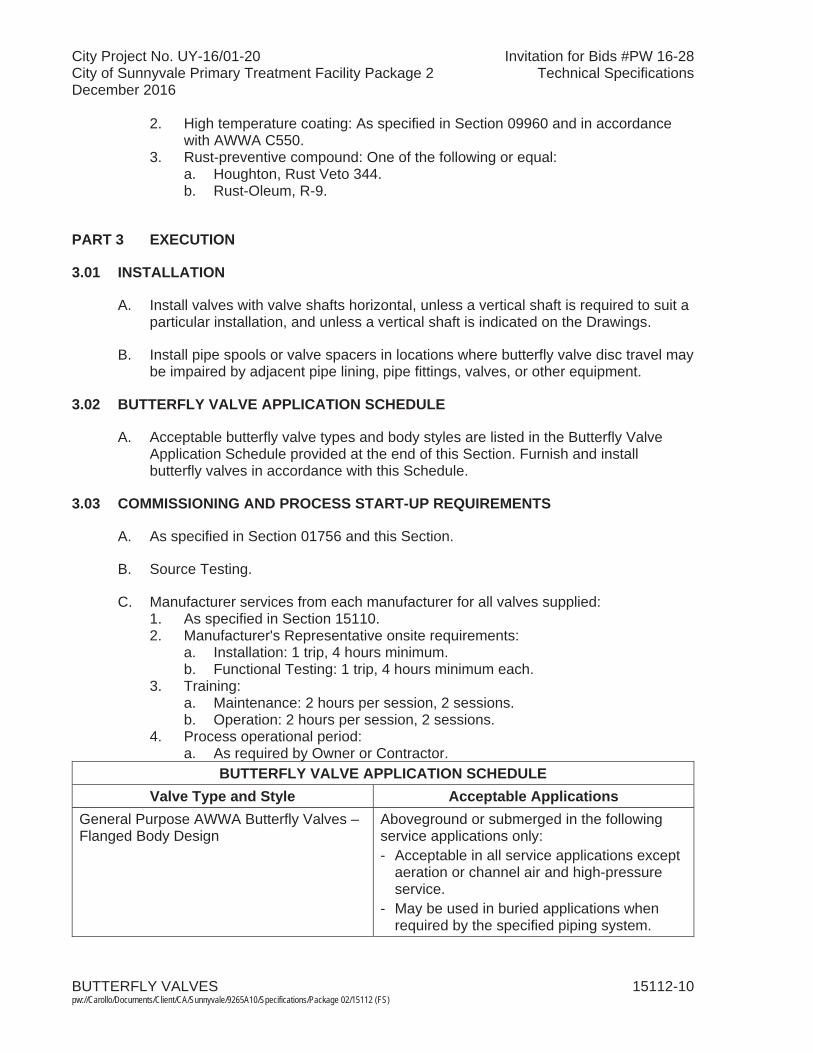
City Project No. UY-16/01-20 Invitation for Bids #PW 16-28City of Sunnyvale Primary Treatment Facility Package 2 Technical SpecificationsDecember 2016
BUTTERFLY VALVES 15112-10pw://Carollo/Documents/Client/CA/Sunnyvale/9265A10/Specifications/Package 02/15112 (FS)
2. High temperature coating: As specified in Section 09960 and in accordance with AWWA C550.
3. Rust-preventive compound: One of the following or equal:a. Houghton, Rust Veto 344.b. Rust-Oleum, R-9.
PART 3 EXECUTION
3.01 INSTALLATION
A. Install valves with valve shafts horizontal, unless a vertical shaft is required to suit a particular installation, and unless a vertical shaft is indicated on the Drawings.
B. Install pipe spools or valve spacers in locations where butterfly valve disc travel may be impaired by adjacent pipe lining, pipe fittings, valves, or other equipment.
3.02 BUTTERFLY VALVE APPLICATION SCHEDULE
A. Acceptable butterfly valve types and body styles are listed in the Butterfly Valve Application Schedule provided at the end of this Section. Furnish and install butterfly valves in accordance with this Schedule.
3.03 COMMISSIONING AND PROCESS START-UP REQUIREMENTS
A. As specified in Section 01756 and this Section.
B. Source Testing.
C. Manufacturer services from each manufacturer for all valves supplied:1. As specified in Section 15110. 2. Manufacturer's Representative onsite requirements:
a. Installation: 1 trip, 4 hours minimum.b. Functional Testing: 1 trip, 4 hours minimum each.
3. Training:a. Maintenance: 2 hours per session, 2 sessions. b. Operation: 2 hours per session, 2 sessions.
4. Process operational period:a. As required by Owner or Contractor.
BUTTERFLY VALVE APPLICATION SCHEDULEValve Type and Style Acceptable Applications
General Purpose AWWA Butterfly Valves – Flanged Body Design
Aboveground or submerged in the following service applications only:- Acceptable in all service applications except
aeration or channel air and high-pressure service.
- May be used in buried applications when required by the specified piping system.

City Project No. UY-16/01-20 Invitation for Bids #PW 16-28City of Sunnyvale Primary Treatment Facility Package 2 Technical SpecificationsDecember 2016
BUTTERFLY VALVES 15112-11pw://Carollo/Documents/Client/CA/Sunnyvale/9265A10/Specifications/Package 02/15112 (FS)
BUTTERFLY VALVE APPLICATION SCHEDULEValve Type and Style Acceptable Applications
General Purpose AWWA Butterfly Valves – Mechanical Joint Body Design
Buried in the following service applications only:- Acceptable in all service applications except
aeration or channel air and high-pressure service.
General Purpose AWWA Butterfly Valves – Lugged Body Design
Not allowed.
General Purpose AWWA Butterfly Valves – Wafer (not lugged) Body Design
Not allowed.
General Purpose AWWA Butterfly Valves – Grooved End Body Design
Aboveground, in sizes 20-inch and less, with piping system test pressure less than 100 psi, and in the following service applications only:- Acceptable in all service applications, except
aeration or channel air, oxygen and ozone service, where piping for that service is specified in the Piping Schedule to have grooved end joints.
High Pressure Butterfly Valves – Flanged Body Design
Service applications with piping system test pressure greater than 250 psi. Acceptable in aboveground and buried installations.
High Pressure Butterfly Valves – Wafer or Lugged Wafer Body Design
Not allowed.
Industrial Class Butterfly Valves – LuggedBody Design
Aboveground in the following service applications only:- Aeration Air Systems. - Channel Air Systems. - Natural Gas Systems. - Digester Gas Systems. - Chilled and Hot Water Systems.
Industrial Class Butterfly Valves – Wafer (not lugged) Body Design
Not allowed.
Stainless Steel Butterfly Valves - LuggedBody Design
Aboveground in the following service applications only:- Oxygen Systems. - Ozone Systems.
Stainless Steel Butterfly Valves – Wafer (not lugged) Body Design
Not allowed.
END OF SECTION

City Project No. UY-16/01-20 Invitation for Bids #PW 16-28City of Sunnyvale Primary Treatment Facility Package 2 Technical SpecificationsDecember 2016
CHECK VALVES 15114-1 pw://Carollo/Documents/Client/CA/Sunnyvale/9265A10/Specifications/Package 02/15114 (FS)
SECTION 15114
CHECK VALVES
PART 1 GENERAL
1.01 SUMMARY
A. Section includes:1. Swing.2. Cushioned swing.3. Plastic swing check.4. High-pressure gas.5. Plastic ball check valves.
B. Related sections:1. The Contract Documents are complementary; what is called for by one is as
binding as if called for by all.2. It is the Contractor's responsibility for scheduling and coordinating the Work of
subcontractors, suppliers, and other individuals or entities performing or furnishing any of Contractor's Work.
3. The following Sections are related to the Work described in this Section. This list of Related Sections is provided for convenience only and is not intended to excuse or otherwise diminish the duty of the Contractor to see that the completed Work complies accurately with the Contract Documents:a. Section 01756 - Commissioning and Process Start-Up.b. Section 15110 - Common Work Results for Valves.
1.02 REFERENCES
A. American Society of Mechanical Engineers (ASME): 1. B16.1 - Gray Iron Pipe Flanges and Flanged Fittings: Classes 25, 125, and
250.2. B16.5 - Pipe Flanges and Flanged Fittings: NPS 1/2 through NPS 24 Inch
Standard.
B. American Water Works Association (AWWA):1. C508 - Standard for Swing-Check Valves for Waterworks Service 2 Inch
Through 24 Inch (50-mm Through 600-mm) NPS.
C. ASTM International (ASTM):1. A 126 - Standard Specification for Gray Iron Castings for Valves, Flanges, and
Pipe Fittings.2. A 313 - Standard Specification for Stainless Steel Spring Wire.3. A 536 - Standard Specification for Ductile Iron Castings.4. B 582 - Standard Specification for Nickel-Chromium-Iron-Molybdenum-Copper
Alloy Plate, Sheet, and Strip.5. B 584 - Standard Specification for Copper Alloy Sand Castings for General
Applications.

City Project No. UY-16/01-20 Invitation for Bids #PW 16-28City of Sunnyvale Primary Treatment Facility Package 2 Technical SpecificationsDecember 2016
CHECK VALVES 15114-2 pw://Carollo/Documents/Client/CA/Sunnyvale/9265A10/Specifications/Package 02/15114 (FS)
1.03 SYSTEM DESCRIPTION
A. Design requirements:1. Check valves: When not otherwise specified as indicated on the Drawings,
provide check valves suitable for service as follows:a. In either horizontal or vertical position.b. Suitable for service working pressures up to 150 pounds per square inch
gauge.
1.04 SUBMITTALS
A. As specified in Section 15110.
PART 2 PRODUCTS
2.01 SWING CHECK VALVES
A. Valves 1/4 inch through 3 inches: 1. Manufacturers: One of the following or equal:
a. Crane Valve Company, Number 36.b. Lunkenheimer Company, Figure 554Y.
2. Valve design:a. Threaded joints.b. Y-pattern body with integral seat.c. Hinged disc.d. Access to valve seat for regrinding without disassembly of piping.
3. Materials:a. Body, cap, hinge, and disc: Bronze.
B. Valves 4 inches through 24 inches: 1. Manufacturers: One of the following or equal:
a. Kennedy, Figure 106LW or M&H, Model 159. b. Mueller Company, Model A-2600.c. APCO Model 250.d. Crispin SWL Series.
2. Valve design:a. In accordance with AWWA C508.b. Constructed to permit top entry and removal of internal components
without removing the valve.c. Equipped with outside lever and weight.
3. Materials:a. Body: Cast iron, ASTM A 126 Class B or ASTM A 536 Gr. 65-45-12
Ductile Iron. b. Disc:
1) 4-inch valves: Bronze or stainless steel. 2) 6 inches and larger valves: Bronze faced or stainless steel. 3) Rubber seat Buna-N or EPDM.
c. Hinge pins: Stainless steel.
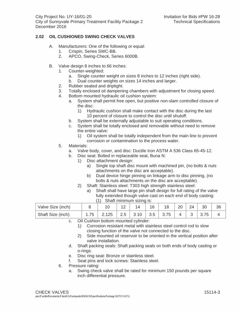
City Project No. UY-16/01-20 Invitation for Bids #PW 16-28City of Sunnyvale Primary Treatment Facility Package 2 Technical SpecificationsDecember 2016
CHECK VALVES 15114-3 pw://Carollo/Documents/Client/CA/Sunnyvale/9265A10/Specifications/Package 02/15114 (FS)
2.02 OIL CUSHIONED SWING CHECK VALVES
A. Manufacturers: One of the following or equal:1. Crispin, Series SWC-BB. 2. APCO, Swing-Check, Series 6000B.
B. Valve design 8 inches to 66 inches: 1. Counter-weighted:
a. Single counter weight on sizes 8 inches to 12 inches (right side). b. Dual counter weights on sizes 14 inches and larger.
2. Rubber seated and driptight.3. Totally enclosed oil dampening chambers with adjustment for closing speed.4. Bottom mounted hydraulic oil cushion system:
a. System shall permit free open, but positive non-slam controlled closure of the disc:1) Hydraulic cushion shall make contact with the disc during the last
10 percent of closure to control the disc until shutoff.b. System shall be externally adjustable to suit operating conditions.c. System shall be totally enclosed and removable without need to remove
the entire valve:1) Oil system shall be totally independent from the main line to prevent
corrosion or contamination to the process water.5. Materials:
a. Valve body, cover, and disc: Ductile Iron ASTM A 536 Class 65-45-12. b. Disc seat: Bolted in replaceable seat, Buna N:
1) Disc attachment design:a) Single top shaft disc mount with machined pin, (no bolts & nuts
attachments on the disc are acceptable). b) Dual device hinge pinning on linkage arm to disc pinning, (no
bolts & nuts attachments on the disc are acceptable). 2) Shaft: Stainless steel: T303 high strength stainless steel:
a) Shaft shall have large pin shaft design for full rating of the valve fully extended though valve cast on each end of body casting: (1) Shaft minimum sizing is:
Valve Size (inch) 8 10 12 14 16 18 20 24 30 36
Shaft Size (inch) 1.75 2.125 2.5 3 10 3.5 3.75 4 3 3.75 4 c. Oil Cushion bottom mounted cylinder:
1) Corrosion resistant metal with stainless steel control rod to slow closing function of the valve not connected to the disc.
2) Side mounted oil reservoir to be oriented in the vertical position after valve installation.
d. Shaft packing seals: Shaft packing seals on both ends of body casting or o-rings.
e. Disc ring seat: Bronze or stainless steel. f. Seat pins and lock screws: Stainless steel.
6. Pressure rating:a. Swing check valve shall be rated for minimum 150 pounds per square
inch differential pressure.
City Project No. UY-16/01-20 Invitation for Bids #PW 16-28City of Sunnyvale Primary Treatment Facility Package 2 Technical SpecificationsDecember 2016
CHECK VALVES 15114-4 pw://Carollo/Documents/Client/CA/Sunnyvale/9265A10/Specifications/Package 02/15114 (FS)
2.03 PLASTIC SWING CHECK VALVES
A. Manufacturers: One of the following or equal:1. Spears.2. ASAHI.
B. Valve Design:1. Top entry swing check type, solid thermoplastic construction having no metal
to media contact, suitable for horizontal and vertical installations. 2. All valve components shall be replaceable.3. EPDM O-ring sealed drain plug to allow quick-flush of any accumulated debris
from bottom of value.4. Flanged ANSI Class 125 end connections.5. External lever and weight to assist the disc in closing faster.
C. Materials:1. Body: Polyvinyl chloride (PVC) or Chlorinated polyvinyl chloride (CPVC) to
match piping material. 2. Valve: Polyvinyl chloride (PVC) or Chlorinated polyvinyl chloride (CPVC) to
match piping material. 3. Seal: EPDM. 4. All other components shall match the material used for valve body, except
bolts, nuts, and washers, which shall be Type 304 stainless steel.
2.04 FLAPPER TYPE CHECK VALVES
A. As specified in Section 11376A.
2.05 PLASTIC BALL CHECK VALVES
A. Manufacturers: One of the following or equal:1. Chemtrol Division of Nibco.2. Georg Fischer Piping Systems. 3. Plast-O-Matic Valves, Inc.
B. Valves: Ball type:1. Material: Polyvinyl chloride. 2. End connection: Double or single union-type.3. Seals: Viton.
C. Valve body material:1. Polyvinyl chloride (PVC), chlorinated polyvinyl chloride (CPVC), Polypropylene
(PP) or polyvinylidene fluoride (PVDF), as best suited for each individual service condition.
D. Union connections material:1. NPT or socket ends conforming to ASME B16.5 pipe flanges and flange
fittings, Class 150.
City Project No. UY-16/01-20 Invitation for Bids #PW 16-28City of Sunnyvale Primary Treatment Facility Package 2 Technical SpecificationsDecember 2016
CHECK VALVES 15114-5 pw://Carollo/Documents/Client/CA/Sunnyvale/9265A10/Specifications/Package 02/15114 (FS)
E. Seats and seals material: 1. EPDM, Buna-N, or Viton.
F. Maximum inlet pressure rating: 1. PVC, CPVC or PVDF: 150 pound per square inch at 77 degrees Fahrenheit.2. PP: 100 pounds per square inch at 77 degrees Fahrenheit.
PART 3 EXECUTION
3.01 INSTALLATION
A. Install valves as specified in Section 15110 and the manufacturer's instructions.
B. Flapper type check valves:1. Install with proper orientation of flow direction arrow on valve body.2. When installed in horizontal pipelines, mount with shaft on vertical locations.3. When mounted in a vertical pipeline, directly downstream of an elbow, mount
with the shaft perpendicular to the outermost portion of the elbow.4. Mount on downstream side of discharge silencer when used on positive
displacement and centrifugal blowers.
3.02 COMMISSIONING AND PROCESS START-UP REQUIREMENTS
A. As specified in Section 01756 and this Section.
B. Source Testing.
C. Manufacturer services from each manufacturer for all valves supplied:1. As specified in Section 15110. 2. Only required for valve 4 inches and larger:
a. Manufacturer's Representative onsite requirements:1) Installation: 1 trip, 4 hours minimum.2) Functional Testing: 1 trip, 4 hours minimum each.
b. Training:1) Maintenance: 2 hours per session, 2 sessions. 2) Operation: 2 hours per session, 2 sessions.
3. Process operational period:a. As required by Owner or Contractor.
3.03 ADJUSTING
A. Adjust cushioned swing check valves in the field by means of external adjustment devices to minimize pressure surges.
B. Adjust weight on swing check valves to affect proper closing action on equipment shutdown.
END OF SECTION

City Project No. UY-16/01-20 Invitation for Bids #PW 16-28City of Sunnyvale Primary Treatment Facility Package 2 Technical SpecificationsDecember 2016
GATE, GLOBE, AND ANGLE VALVES 15115-1 pw://Carollo/Documents/Client/CA/Sunnyvale/9265A10/Specifications/Package 02/15115 (FS)
SECTION 15115
GATE, GLOBE, AND ANGLE VALVES
PART 1 GENERAL
1.01 SUMMARY
A. Section includes: Gate, globe, angle, plug disc and plain hose valves, and yard hydrants.
B. Related sections:1. The Contract Documents are complementary; what is called for by one is as
binding as if called for by all.2. It is the Contractor's responsibility for scheduling and coordinating the Work of
subcontractors, suppliers, and other individuals or entities performing or furnishing any of Contractor's Work.
3. The following Sections are related to the Work described in this Section. This list of Related Sections is provided for convenience only and is not intended to excuse or otherwise diminish the duty of the Contractor to see that the completed Work complies accurately with the Contract Documents:a. Section 01756 - Commissioning and Process Start-Up.b. Section 15110 - Common Work Results for Valves.
1.02 REFERENCES
A. American Society of Mechanical Engineers (AMSE).
B. American Water Works Association (AWWA):1. C515 - Standard for Reduced-Wall, Resilient-Seated Gate Valves for Water
Supply Services.2. C550 - Protective Interior Coatings for Valves and Hydrants.
C. ASTM International (ASTM):1. B 98 - Standard Specification for Copper-Silicon Alloy Rod, Bar, and Shapes.
1.03 SUBMITTALS
A. As specified in Section 15110.
B. Interior epoxy coatings: Affidavit of compliance attesting that epoxy coatings applied to interior surfaces of valves comply in accordance with all provisions of AWWA C550.

City Project No. UY-16/01-20 Invitation for Bids #PW 16-28City of Sunnyvale Primary Treatment Facility Package 2 Technical SpecificationsDecember 2016
GATE, GLOBE, AND ANGLE VALVES 15115-2 pw://Carollo/Documents/Client/CA/Sunnyvale/9265A10/Specifications/Package 02/15115 (FS)
PART 2 PRODUCTS
2.01 GATE VALVES
A. Gate valves aboveground:1. Valves less than 3 inches in size for clean water and air service:
a. Manufacturers: One of the following or equal:1) Crane, Figure 431.2) Jenkins, Figure 47.3) Lunkenheimer Company, Figure 2151.
b. Design:1) Size and configuration: Indicated on the Drawings. 2) Manufacturer's standard bronze, solid wedge disc, rising stem,
screwed end, Class 150 pounds.2. Valves 3 inches in size and larger:
a. Manufacturers: One of the following or equal:1) M&H/Kennedy Valve Company.2) Mueller.3) American Flow Control, Series 2500.
b. Design:1) Size, material, configuration: Indicated on the Drawings. 2) Resilient wedge type in accordance with AWWA C515.3) Flange, iron body, and bonnet rated for 200 pound working pressure:
a) Provide O-ring seal between valve body and bonnet.4) Cast iron wedge encapsulated in nitrile rubber and capable of sealing
in either flow direction.5) Bronze stem with double or triple O-ring or braided packing stem
seals.6) Rising stem configuration with handwheel diameter sized to allow
opening of valve with no more than a 40-pound pull.7) Coat interior and exterior surfaces of valve body and bonnet with
fusion-bonded epoxy in accordance with AWWA C550.
B. Gate valves underground or submerged: 1. Manufacturers: One of the following or equal:
a. M&H/Kennedy Valve Company.b. Mueller Company.c. American Flow Control.
2. Design:a. Size, material, configuration: Indicated on the Drawings. b. Resilient wedge type in accordance with AWWA C515.c. Stem:
1) Iron body, resilient seat, non-rising stem, double O-ring stem seal.2) Non-rising stem configuration.
d. Cast iron wedge encapsulated in nitrile rubber and capable of sealing in either flow direction.
e. Bronze stem with double or triple O-ring or braided packing stem seals.f. Coat interior and exterior surfaces of valve body and bonnet with fusion-
bonded epoxy in accordance with AWWA C550.
City Project No. UY-16/01-20 Invitation for Bids #PW 16-28City of Sunnyvale Primary Treatment Facility Package 2 Technical SpecificationsDecember 2016
GATE, GLOBE, AND ANGLE VALVES 15115-3 pw://Carollo/Documents/Client/CA/Sunnyvale/9265A10/Specifications/Package 02/15115 (FS)
g. Valve operator: 1) Underground: Provide standard AWWA 2-inch operating nut,
matching valve key, and valve box for operating stem.2) Submerged: Handwheel diameter sized to allow opening of valve
with no more than a 40-pound pull.
C. Knife gate valves (non-buried applications): 1. Manufacturers: One of the following or equal:
a. DeZurick SPX, KGL.b. ITT Fabri-Valve, C37.
2. Design:a. Size and configuration: Indicated on the Drawings. b. Suitable for service under pressures equal to and less than 150 pounds
per square inch gauge.c. Full round port, metal seated, raised face design.d. Flanged wafer design drilled and tapped to ASME Class 125/150
standard.e. Rounded gate with beveled edge, finish-ground to 32 RMS, maximum, on
both sides.f. Body to incorporate guides and jams to assist in seating.g. Materials:
1) Body: Cast or ductile iron or cast steel, with Type 316 stainless steel lining or cast Type 316 stainless steel.
2) Wetted components (including gate): Type 316 stainless steel.3) Yoke sleeve: Acid resisting bronze or aluminum bronze.4) Packing: PTFE.
h. Outside screw and yoke (OS&Y) with handwheel operator.
D. Buried Knife Gate Valves: 1. Size: Above 48-inches. 2. Manufacturers: One of the following or equal.
a. Dezurik-Hilton, H-200-B. 3. Design:
a. Size and Configuration: Indicated on the Drawings.b. Provide bonneted valve for buried service.c. Suitable for service under pressures equal to and less than 50 pounds per
square inch gauge.d. Provide stem cover.e. Flanges: Compatible with adjacent piping system. f. Manual bevel gear operator with handwheel. Provide handwheel operator
centerlines approximately 42 inches above concrete pad elevation. g. Two-way flow shut-off type.h. Port Diameter to meet or exceed MSS SP-81.i. Provide drip-tight resilient seats.j. Materials:
1) Valve Body, bonnet, Gate, and Stem: 316 Stainless Steel.2) Wetted Parts: 316 Stainless Steel.3) Packing: Teflon-Acrylic. 4) Seal Ring: Neoprene.
City Project No. UY-16/01-20 Invitation for Bids #PW 16-28City of Sunnyvale Primary Treatment Facility Package 2 Technical SpecificationsDecember 2016
GATE, GLOBE, AND ANGLE VALVES 15115-4 pw://Carollo/Documents/Client/CA/Sunnyvale/9265A10/Specifications/Package 02/15115 (FS)
2.02 GLOBE AND ANGLE VALVES
A. General purpose globe and angle valves:1. Valves 3 inches and smaller:
a. Manufacturers: One of the following or equal: 1) Except in welded steel piping:
a) Crane, No. 1 Globe or No. 2 Angle.b) Lunkenheimer Company Figure No. 2140 Globe or No. 2141
Angle.2) In Welded steel piping:
a) Crane, No. 351.b) Lunkenheimer Company, Figure No. 1123; or equal with flanged
ends.b. Design:
1) Size and configuration: Indicated on the Drawings. 2) Valve: Class 125 threaded ends, rated for 250 degrees Fahrenheit at
pressure of 170 pounds per square inch.2. Valves larger than 3 inches:
a. Manufacturers: One of the following or equal:1) Crane, No. 351.2) Lunkenheimer Company, Figure No. 1123.
b. Design:1) Size and configuration: Indicated on the Drawings.
3. Plug disc globe valves: for throttling or for severe service:a. Manufacturers: One of the following or equal:
1) Crane, No. 212P or No. 384P.2) Lunkenheimer Company, 72-PS or 73-PS1.
b. Design:1) Size and configuration: Indicated on the Drawings. 2) Material: Iron body stainless steel trimmed plug type seat and disc.
2.03 NEEDLE VALVES
A. Manufacturers: One of the following or equal:1. Powell, Figure No. 180.2. Lunkenheimer Company, Figure No. 906-BS or No. 907-BS. 3. Crane No. 88 or No. 89.
B. Design:1. Size and configuration: Indicated on the Drawings.
2.04 HOSE VALVES AND YARD HYDRANTS
A. Hose valves:1. Manufacturers:
a. Globe threaded valve: One of the following or equal:1) Crane, No. 7TF.2) Stockham, Figure No. B22T.
City Project No. UY-16/01-20 Invitation for Bids #PW 16-28City of Sunnyvale Primary Treatment Facility Package 2 Technical SpecificationsDecember 2016
GATE, GLOBE, AND ANGLE VALVES 15115-5 pw://Carollo/Documents/Client/CA/Sunnyvale/9265A10/Specifications/Package 02/15115 (FS)
b. Angle threaded valve: One of the following or equal:1) Crane, No. 17TF.2) Stockham, Figure No. B222T.
2. Provide angle threaded valves at hose bibs unless noted otherwise.3. Design:
a. Size and configuration: Indicated on the Drawings. b. Valve: Globe or angle valve with threaded ends. c. Disc: Renewable, made of Teflon or Buna-N.d. Threaded ends rated for a pressure of 200 pounds per square inch.
B. Freezeless yard hydrant:1. Manufacturers: One of the following or equal:
a. Kupferle Foundry Company:1) #1 Total Eclipse Yard Hydrant - 3/4 inch and 1 inch.
b. Murdock Company:1) #M-75 – 3/4 inch or #M100 - 1 inch.
c. Zurn Company:1) #1385 - 3/4 inch or 1 inch.
2. Design:a. Self-draining, non-freezing, compression type:
1) Inlet connection size: Indicated on the Drawings. 2) Outlet connection size: Indicated on the Drawings. 3) Materials:
a) Exterior casing pipe material: Indicated on the Drawings. b) Interior operating rod material: Indicated on the Drawings. c) Casing guard material: Indicated on the Drawings. d) Principal interior operating parts material: brass and/or bronze
and removable from yard hydrant for servicing without excavation.
4) Provide 4 Spoke, Ball Wheel Handle operated.
C. Freezeless post hydrants:1. Manufacturers: The following or equal:
a. McWane-Wade:1) 8900 Freezeless Post Hydrant.
b. Kupferle Foundry Company:1) #2 Eclipse Post Hydrant.
c. Mueller Company:1) #A-411 Post Hydrant.
d. Murdock Company:1) #M-200 Post Hydrant.
2. Design:a. Self-draining, non-freezing, compression type with a 1-1/2-inch valve
opening.b. Inlet connection size: Indicated on the Drawings. c. Outlet connection size: Indicated on the Drawings. d. Materials:
1) Exterior casing pipe material: Indicated on the Drawings. 2) Interior operating rod material: Indicated on the Drawings.
City Project No. UY-16/01-20 Invitation for Bids #PW 16-28City of Sunnyvale Primary Treatment Facility Package 2 Technical SpecificationsDecember 2016
GATE, GLOBE, AND ANGLE VALVES 15115-6 pw://Carollo/Documents/Client/CA/Sunnyvale/9265A10/Specifications/Package 02/15115 (FS)
3) Top stock material: Indicated on the Drawings. 4) Principal interior operating parts material: Brass and/or bronze and
removable from hydrant for servicing without excavation.e. Provide 1-1/2-inch pentagon operating nut operated by a hydrant wrench
or 10-inch hand wheel:1) Manufacturers: One of the following or equal:
a) Kupferle Foundry Company.
PART 3 EXECUTION
3.01 INSTALLATION
A. Install valves as specified in Section 15110 and manufacturer's instructions.
B. Mount yard hydrants on minimum 1-inch supply pipe or size indicated on the Drawings.
C. Mount Post hydrants on minimum 2-inch supply pipe or size indicated on the Drawings.
D. Set yard and post hydrants in 4 cubic feet of 3/4 inch minimum crushed stone surrounding valve body to allow for proper drainage:1. Install in accordance with AWWA recommendations for hydrants.
3.02 COMMISSIONING AND PROCESS START-UP REQUIREMENTS
A. As specified in Section 01756 and this Section.
B. Source testing.
C. Manufacturer services from each manufacturer for all valves supplied:1. As specified in Section 15110. 2. Only required for valves 4 inches and larger:
a. Manufacturer's Representative onsite requirements:1) Installation: 1 trip, 4 hours minimum.
a) Knife gate valves: 1 trip, 2 day minimum.2) Functional Testing: 1 trip, 4 hours minimum each.
a) Knife gate valves: 1 trip, 2 day minimum. b. Training:
1) Maintenance: 2 hours per session, 2 sessions. a) Knife gate valves: 4 hours per session.
2) Operation: 2 hours per session, 2 sessions.a) Knife gate valves: 4 hours per session.
3. Process operational period:a. As required by Owner or Contractor.
END OF SECTION

City Project No. UY-16/01-20 Invitation for Bids #PW 16-28City of Sunnyvale Primary Treatment Facility Package 2 Technical SpecificationsDecember 2016
PLUG VALVES 15116-1 pw://Carollo/Documents/Client/CA/Sunnyvale/9265A10/Specifications/Package 02/15116 (FS)
SECTION 15116
PLUG VALVES
PART 1 GENERAL
1.01 SUMMARY
A. Section includes:1. Non-lubricated plug valves. 2. Lubricated plug valves.3. Multi-port plug valves.
B. Related sections:1. The Contract Documents are complementary; what is called for by one is as
binding as if called for by all.2. It is the Contractor's responsibility for scheduling and coordinating the Work of
subcontractors, suppliers, and other individuals or entities performing or furnishing any of Contractor's Work.
3. The following Sections are related to the Work described in this Section. This list of Related Sections is provided for convenience only and is not intended to excuse or otherwise diminish the duty of the Contractor to see that the completed Work complies accurately with the Contract Documents:a. Section 01756 - Commissioning and Process Start-Up.b. Section 09960 - High-Performance Coatings.c. Section 15110 - Common Work Results for Valves.
1.02 REFERENCES
A. American Water Works Association (AWWA):1. C606 - Grooved and Shouldered Joints.2. C517 - Resilient-Seated Cast Iron Eccentric Plug Valves.
B. ASTM International (ASTM):1. A 126 - Standard Specification for Gray Iron Castings for Valves, Flanges, and
Pipe Fittings.2. A 536 - Standard Specification for Ductile Iron Castings.
1.03 SUBMITTALS
A. As specified in Section 15110.
City Project No. UY-16/01-20 Invitation for Bids #PW 16-28City of Sunnyvale Primary Treatment Facility Package 2 Technical SpecificationsDecember 2016
PLUG VALVES 15116-2 pw://Carollo/Documents/Client/CA/Sunnyvale/9265A10/Specifications/Package 02/15116 (FS)
PART 2 PRODUCTS
2.01 NON-LUBRICATED PLUG VALVES
A. Manufacturers: One of the following or equal:1. DeZURIK, "PEC." 2. Clow Valve.
B. Design:1. Type: Non-lubricated eccentric type, in accordance with AWWA C517.
a. 3 inches and under: Threaded body.b. 4 inches and larger: Flanged body.
2. Plug face: Resilient material that operates satisfactorily at a temperature of 180 degrees Fahrenheit continuous and 215 degrees Fahrenheit intermittent, except for valves in compressed air or digester gas service:a. Valves in compressed air service: Resilient material suitable for
continuous duty at 250 degrees Fahrenheit.b. Valves in digester gas service: Resilient material suitable for petroleum or
digester gas at continuous duty at 180 degrees Fahrenheit.3. Compression washer: Provide flat compression washer made of Teflon, or of a
material having equal physical characteristics on valve stem between plug and bonnet.
4. Stem seals: Provide stem seals serviceable without unbolting the valve bonnet assembly.
5. Grit excluders: Provide PTFE grit excluders at upper plug journals to prevent entry of foreign solids in bearing area.
6. Clearly mark valves to indicate their open and closed positions.7. Provide valves with ends as required by piping details indicated on the
Drawings. 8. Grooved end body valves:
a. Usage: Plug valves with grooved ends may be used in piping systems specified in the Piping Schedule to have grooved end joints and as indicated on the Drawings.
b. Grooved end joint design: In accordance with AWWA C606.
C. Materials:1. Body and plug: ASTM A 126, Class B, cast-iron with plug face of neoprene or
Buna N material suitable for the intended service as specified under paragraph "Design" above.
2. Body seats in valves 3-inch size and larger: Provide with overlay of not less than 90-percent nickel and minimum thickness of 1/8 inch on surfaces contacting the plug face.
3. Stem seal: Buna V-flex or TFE.4. Stem bearing and bottom bearing: Type 316 stainless steel. 5. Internal parts, except the body and plug: Type 316 stainless steel. 6. Exposed nuts, bolts, and washers: Zinc plated. Exception: Exposed nuts,
bolts, and washers for buried service: Stainless steel.

City Project No. UY-16/01-20 Invitation for Bids #PW 16-28City of Sunnyvale Primary Treatment Facility Package 2 Technical SpecificationsDecember 2016
PLUG VALVES 15116-3 pw://Carollo/Documents/Client/CA/Sunnyvale/9265A10/Specifications/Package 02/15116 (FS)
2.02 PLUG VALVES FOR CHEMICAL SERVICES
A. Provide plug valves for chemical services where specifically indicated on the Drawings.
B. Manufacturers: One of the following or equal:1. DeZURIK.2. The valve manufacturer shall have a minimum of 7 years' experience in the
manufacturing of cylindrical eccentric plug valves for similar service. The manufacturer shall be ISO 9000 certified. Successful experience data and certifications shall be furnished upon request.
C. Non-lubricated eccentric type.
D. Design:1. Suitable for service under minimum working pressure of 150 pounds per
square inch gauge.2. Service:
a. Valves will be located on drain lines from chemical storage areas.b. Valves are expected to be normally exposed to light concentration
solution of stored chemicals.c. Valve may occasionally be exposed to the chemical solution at its maximum
concentration listed herein (such as in the case of a chemical spill):1) Phosphoric Acid: Up to 10-percent solution by weight.
3. Plug Face:a. EPDM material.
4. Provide 316 stainless steel cup at bottom bearing area to stop media from leaking into journal area.
5. Provide multiple v-ring type stem seals externally adjustable without removing the bonnet or actuator from the valve under the specified rated pressure. Packing shall be TFE material.
6. The interference between the plug face and body seat, with the plug in the closed position, shall be externally adjustable in the field with the valve in theline under the specified rated pressure.
7. Clearly mark valves to indicate their open and closed positions.8. Provide valves with ends as required by piping details indicated on the
Drawings.9. Port areas for valves through 20 inches shall be at least 80 percent of full pipe
area.10. Valves and gear actuators:
a. Valves and gear actuators shall have seals on all shafts and gaskets on the valve and actuator covers to prevent the entry of water.
b. All submerged or buried valve actuators shall be completely packed withlubricant to eliminate all voids.
c. Actuator mounting brackets for buried or submerged service shall be totally enclosed and shall have gasket seals on all units. Units with aluminum housings are not acceptable.
d. Worm gear actuators shall be Limitorque Model HBC-4 Series or DeZURIK G series.

City Project No. UY-16/01-20 Invitation for Bids #PW 16-28City of Sunnyvale Primary Treatment Facility Package 2 Technical SpecificationsDecember 2016
PLUG VALVES 15116-4 pw://Carollo/Documents/Client/CA/Sunnyvale/9265A10/Specifications/Package 02/15116 (FS)
e. Valve actuators shall be tested and certified per the requirements of AWWA C504. All actuators shall be factory mounted and tested by the valve manufacturer prior to shipment.
f. All gearing shall be enclosed in a cast iron housing and be suitable for running in a lubricant with elastomeric lip seals provided on all shafts to prevent entry of dirt and water into the actuator. Seals shall be located outside the bearings. The actuator shaft and the quadrant shall be supported on permanently lubricated bronze bearings.
g. Units with aluminum housings are not acceptable.h. Aboveground actuators shall clearly indicate valve position and an
adjustable stop shall be provided to set closing torque. Stops shall be capable of withstanding 300 foot-pounds of input torque.
i. Valve packing adjustment on non-submerged valves shall be accessible without removing the actuator from the valve.
j. Rim pull shall not exceed 80 pounds at the valve design pressure.k. Handwheel diameter shall be no greater than twice the diameter of the
gear sector.l. Valve to actuator or nut connection to valve plug shall have a hex, square,
or splined shaft to mate with an approved square nut or actuator. Pinned valve shafts are not acceptable.
m. All exposed nuts, bolts, springs, and washers for valves and gear actuators in buried or submerged service shall be 316 stainless steel.
E. Materials:1. Body: ASTM A 126 Class B cast iron with plug face of material suitable for the
intended service, as specified in Article 2.03 Paragraph D of this Section. Body shall be soft rubber-lined.
2. Plug: Stainless steel.3. Body seats in valves 3 inches in size and larger: Provide with overlay of not
less than 90-percent nickel and minimum thickness of 1/8 inch on surfaces contacting the plug face.
4. Stem bearing and bottom bearing: Stainless steel Type 316. Provide 316 stainless steel cup at bottom bearing area to stop media from leaking into journal area.
5. Internal parts, except the body, and plug: Type 316 stainless steel, Monel, or nickel.
6. Exposed nuts, bolts, and washers: zinc plated. Exception: Exposed nuts, bolts, and washers for buried service: Stainless steel.
7. Bonnet: Stainless steel.
2.03 LUBRICATED PLUG VALVES
A. Manufacturers: One of the following or equal:1. Nordstrom.2. Walworth.
B. Type: Semi-steel tapered plug valves.

City Project No. UY-16/01-20 Invitation for Bids #PW 16-28City of Sunnyvale Primary Treatment Facility Package 2 Technical SpecificationsDecember 2016
PLUG VALVES 15116-5 pw://Carollo/Documents/Client/CA/Sunnyvale/9265A10/Specifications/Package 02/15116 (FS)
C. Design:1. Plug removable through top of valve.2. Combined lubricant screw and grease gun fitting, of the type where the
pressure of the grease can be used to raise the plug slightly off its seat.
D. Where indicated on the Drawings or specified, provide plug valves with high head extension and floor stand with indicator. Provide worm gear-operated valves with worm shaft extension and floor stand, and with indicator supplied by manufacturer of plug valve:1. Equip floor stands serving plug valves with individual operating wrenches.
2.04 MULTI-PORT PLUG VALVES FOR SLUDGE SERVICE
A. Manufacturers: One of the following or equal:1. DeZURIK, PTW, for 3-way valve, and PFW for 4-way valve.2. Milliken, equivalent product.
B. Design: Non-lubricated tapered plug type including plugs faced with neoprene, body of cast iron, and stainless steel bearings in the upper and lower journal areas.
C. Furnish valves with single, double, or transfer style plug as indicated on the Drawings or as required.
2.05 VALVE OPERATORS
A. Furnish valves with an operating wrench or worm gear operator:1. Equip valves 4-inch nominal size and smaller with a lever operator.2. Equip valves 6-inch nominal size and larger with a worm gear operator.
B. Valve gear operator actuator shafts shall be supported on permanently lubricated bronze bearings.
2.06 COATING
A. Coat interior metal surfaces as specified in Section 15110.
B. Coat exterior metal surfaces as specified in Section 09960.
PART 3 EXECUTION
3.01 INSTALLATION
A. Install valves as specified in Section 15110 and the manufacturer's instructions.
B. Install valves so that in the closed position the pressure in the pipeline applies a seating head on the valves.
City Project No. UY-16/01-20 Invitation for Bids #PW 16-28City of Sunnyvale Primary Treatment Facility Package 2 Technical SpecificationsDecember 2016
PLUG VALVES 15116-6 pw://Carollo/Documents/Client/CA/Sunnyvale/9265A10/Specifications/Package 02/15116 (FS)
C. Lubrication: Lubricate plug valves and fill extended lubricant pipes with lubricant suitable for service intended.
D. Install valves so that in the open position the plug is located in the top half of the valve body.
3.02 COMMISSIONING AND PROCESS START-UP REQUIREMENTS
A. As specified in Section 01756 and this Section.
B. Manufacturer services from each manufacturer for all valves supplied:1. As specified in Section 15110. 2. Only required for valves 4 inches and larger:
a. Manufacturer's Representative onsite requirements:1) Installation: 1 trip, 4 hours minimum.2) Functional Testing: 1 trip, 4 hours minimum each.
b. Training:1) Maintenance: 2 hours per session, 2 sessions. 2) Operation: 2 hours per session, 2 sessions.
3. Process operational period:a. As required by Owner or Contractor.
4. Source testing.
END OF SECTION
City Project No. UY-16/01-20 Invitation for Bids #PW 16-28City of Sunnyvale Primary Treatment Facility Package 2 Technical SpecificationsDecember 2016
SPECIALTY VALVES 15117-1 pw://Carollo/Documents/Client/CA/Sunnyvale/9265A10/Specifications/Package 02/15117 (FS)
SECTION 15117
SPECIALTY VALVES
PART 1 GENERAL
1.01 SUMMARY
A. Section includes:1. Backflow preventers.2. Field irrigation valves.3. Float valves.4. Hydrostatic pressure relief valves.5. Mud valves.6. Solenoid valves.7. Metal body diaphragm valves.8. Plastic body diaphragm valves.9. Pinch valves.10. Tubing valves.11. Corporation stops.12. Cocks.
B. Related sections:1. The Contract Documents are complementary; what is called for by one is as
binding as if called for by all.2. It is the Contractor's responsibility for scheduling and coordinating the Work of
subcontractors, suppliers, and other individuals or entities performing or furnishing any of Contractor's Work.
3. The following Sections are related to the Work described in this Section. This list of Related Sections is provided for convenience only and is not intended to excuse or otherwise diminish the duty of the Contractor to see that the completed Work complies accurately with the Contract Documents:a. Section 01756 - Commissioning and Process Start-Up.b. Section 15110 - Common Work Results for Valves.
1.02 REFERENCES
A. American Society of Civil Engineers (ASCE):1. 25 - Earthquake-Actuated Automatic Gas Shutoff Devices.
B. American Society of Mechanical Engineers (ASME):1. B16.42 - Ductile Iron Pipe Flanges and Flanged Fittings: Classes 150 and 300.
C. American Water Works Association (AWWA):1. C511 - Standard for Reduced Pressure-Principle Backflow-Prevention
Assembly.2. C800 - Underground Service Line Valves & Fittings (Also Included: Collected
Standards For Service Line Materials).

City Project No. UY-16/01-20 Invitation for Bids #PW 16-28City of Sunnyvale Primary Treatment Facility Package 2 Technical SpecificationsDecember 2016
SPECIALTY VALVES 15117-2 pw://Carollo/Documents/Client/CA/Sunnyvale/9265A10/Specifications/Package 02/15117 (FS)
D. ASTM International (ASTM):1. A 48 - Standard Specification for Gray Iron Castings.2. A 126 - Standard Specification for Gray Iron Casting for Valves, Flanges, and
Pipe Fittings.3. A 276 - Standard Specification for Stainless Steel Bars and Shapes.4. A 536 - Standard Specification for Ductile Iron Castings.5. B 584 - Standard Specification for Copper Alloy Sand Castings for General
Application.
E. National Electrical Manufacturers Association (NEMA): 1. 250 - Enclosures for Electrical Equipment (1000 V Maximum).
1.03 DEFINITIONS
A. NEMA Type 4 enclosure in accordance with NEMA 250.
1.04 SUBMITTALS
A. As specified in Section 15110.
B. Certificates:1. Recertification of all new backflow preventers after installation, start-up, and
testing.
1.05 QUALITY ASSURANCE
A. Manufacturer qualifications: Manufactured by manufacturers whose valves have had successful operational experience in comparable service.
1.06 DELIVERY STORAGE AND HANDLING
A. Protect valves from damage during handling and installation.
PART 2 PRODUCTS
2.01 BACKFLOW PREVENTERS
A. Manufacturers: One of the following or equal:1. Febco backflow prevention:
a. Model 860 all sizes. 2. Zurn/Wilkins:
a. Model 975XL for 1/2 inch through 2 inches. b. Model 975 for sizes 2-1/2 inches, 3 inches, 8 inches, and 10 inches. c. Model 375 and 375DA for sizes 4 inches and 6 inches.
3. Watts regulator: Series 909.
B. Design: Reduced pressure chamber type in accordance with AWWA C511.
City Project No. UY-16/01-20 Invitation for Bids #PW 16-28City of Sunnyvale Primary Treatment Facility Package 2 Technical SpecificationsDecember 2016
SPECIALTY VALVES 15117-3 pw://Carollo/Documents/Client/CA/Sunnyvale/9265A10/Specifications/Package 02/15117 (FS)
C. Lead-Free: For potable water installations not more than a weighted average of 0.25 percent lead when used with respect to the wetted surfaces.
D. Include shutoff valves at each end of backflow preventer with properly located test cocks.
E. Shutoff valves:1. Backflow preventers 2 inches and smaller: Provide with full-port, quarter turn,
resilient seated ball valves.2. Backflow preventers larger than 2 inches: Provide with resilient seated, outside
stem and yoke gate valves.
2.02 FIELD IRRIGATION VALVES
A. As indicated on the landscaping drawings.
2.03 FLOAT VALVES
A. Manufacturers: One of the following or equal:1. Cla-Val Company, Number 124.2. GA Industries, Figure 54.
B. Float valves: Pilot controlled, diaphragm, or piston actuated from hydraulic pressure of liquid flowing through valve.
C. Design:1. Valves: Single seated. Open wide when the float is at low level, and close
driptight at high level.2. Float level: Adjustable in the field.
2.04 HYDROSTATIC PRESSURE RELIEF VALVES
A. Flap gate type:1. Manufacturers: One of the following or equal:
a. Clow Corporation.b. Neenah Foundry Company.
2. Design:a. Provide valves with vertical seat design and offset single pivoted hinge.b. Valve components: Flap gate, body with flanged end, hinge pin, and gate
seat ring.c. Design valve so that flap gate begins to open at a head of 1/3 the inner
diameter of the valve body.d. Mechanically retain gate seat ring in place.
3. Materials:a. Flap gate and body: Cast iron in accordance with ASTM A 126 Class B or
bronze in accordance with ASTM B 584 UNS Number C84400.b. Hinge pin: Bronze of the type specified in the preceding subparagraph or
stainless steel in accordance with ASTM A 276 Type 304.c. Gate seat ring: Neoprene rubber in accordance with ASTM D 2000
Type CB 520 or EPDM.
City Project No. UY-16/01-20 Invitation for Bids #PW 16-28City of Sunnyvale Primary Treatment Facility Package 2 Technical SpecificationsDecember 2016
SPECIALTY VALVES 15117-4 pw://Carollo/Documents/Client/CA/Sunnyvale/9265A10/Specifications/Package 02/15117 (FS)
B. Pop-up type:1. Manufacturers: One of the following or equal:
a. Clow Corporation.b. Neenah Foundry Company.
2. Design:a. Design valve to begin opening at a maximum head of 9 inches.b. Integrally cast locking lugs into body:
1) Prevent groundwater pressure from separating the cover and strainer from the body.
c. The cover and the strainer shall be easily removed by release from the locking lugs.
d. Provide lead seats, poured and peened into grooves on the underside of cover and top of body:1) Machine seats to form lead-to-lead contact when the cover is in
closed position.3. Materials:
a. Cover, body, and strainer: Cast-iron in accordance with ASTM A 126,Class B.
2.05 MUD VALVES
A. Manufacturers: One of the following or equal:1. Clow Corporation, Series F-3075T. 2. Waterman Industries, Inc., Model MV-11.
B. Design:1. Provide mud valves with non-rising stem.2. Provide standard AWWA 2-inch valve nut on stainless steel stem extension to
height required.
C. Materials:1. Body, cover, and yoke: Cast-iron.2. Disc plug: Cast-iron.3. Seat rings: Resilient Neoprene or Buna-N seating face.4. Stem and stem nut: Bronze.5. Cap screws to bolt valve to cast-iron pipe flange: Type 316 stainless steel.
2.06 SOLENOID VALVES
A. 2-way solenoid valves:1. Manufacturers: One of the following or equal:
a. Automatic Switch Company, Series 8210.b. Skinner Electric Valve Division, Series C.
B. 3-way solenoid valves:1. Manufacturers: One of the following or equal:
a. Automatic Switch Company, Series 8320.b. Skinner Electric Valve Division, Type A4.
City Project No. UY-16/01-20 Invitation for Bids #PW 16-28City of Sunnyvale Primary Treatment Facility Package 2 Technical SpecificationsDecember 2016
SPECIALTY VALVES 15117-5 pw://Carollo/Documents/Client/CA/Sunnyvale/9265A10/Specifications/Package 02/15117 (FS)
C. 4-way solenoid valves:1. Manufacturers: One of the following or equal:
a. Automatic Switch Company, Bulletin 8344.b. Skinner Electric Valve Division, Series V9.
D. Design:1. Valves: Suitable for service under the following conditions:
a. Fluid: Utility Water or PW2.b. Temperature of fluid: 80 degrees Fahrenheit.c. Piping test pressure: 175 pounds per square inch gauge.
2. Unless otherwise indicated on the Drawings, provide valves that:a. Minimum NEMA Type 4 enclosure. b. 120 VAC operation.c. Suitable for use as indicated on the Drawings. d. Minimum Class F coil insulation.
3. 2-way valves: Furnish with openings of size equal to or larger than the nominal size designation of the valve.
4. Furnish with manual/bypass operators.
E. Materials:1. Body: 316 Stainless Steel. 2. Seats: Teflon or Buna-N.
2.07 METAL BODY DIAPHRAGM VALVES
A. Manufacturers: One of the following or equal:1. Hill-McCanna.2. ITT Engineered Valves.
B. Design:1. Body: Cast iron, weir type, flanged ends.
C. Materials:1. Diaphragm: Unless otherwise specified below, provide Teflon® diaphragm or
other material suitable for the intended service.2. Bonnet: Cast iron.3. Compressor: Cast iron.4. Handwheel: Cast iron.5. Sleeve: Cast iron.6. Stem: Carbon steel.7. Bolt, nut, and washer: Carbon steel.8. Thrust bearing: Carbon.9. End connector: Cast iron flange.10. Position indicator: Carbon steel.11. Special valve applications:
a. For chlorine solution service, line valves with Teflon® or Kynar®.
D. Electro-hydraulic actuator:1. Manufacturers: One of the following or equal:
a. Barton/ITT Fluid Technology Corporation.
City Project No. UY-16/01-20 Invitation for Bids #PW 16-28City of Sunnyvale Primary Treatment Facility Package 2 Technical SpecificationsDecember 2016
SPECIALTY VALVES 15117-6 pw://Carollo/Documents/Client/CA/Sunnyvale/9265A10/Specifications/Package 02/15117 (FS)
2. Actuator type:a. Control valve with 2-position spring return.b. Pump: Single piston, positive displacement with internal check valve.c. Seals: Buna-N or EPDM.
3. Materials:a. Cylinder housing: Aluminum.b. Output shaft: Stainless steel.c. Yoke: Aluminum.d. Electrical housing: NEMA Type 4.e. Enclosure: NEMA Type 4.
2.08 PLASTIC BODY DIAPHRAGM VALVES
A. Type of service: Use plastic body diaphragm valves in the following services:1. Sodium hypochlorite.2. Sodium bisulfite.3. Polymer solutions.4. Neat polymer.
B. Manufacturers: One of the following or equal:1. Simtech.2. Chemtrol.3. Asahi-America (2-1/2 inches and less only for sodium hypochlorite service).4. Georg Fischer Piping Systems.
C. Materials:1. Body: PVC with reinforcing ribs at body and end connections.2. Diaphragm: Unless otherwise specified below, provide 2 diaphragm layers -
Teflon® diaphragm with EPDM backing or other material suitable for the intended use:a. For sodium hypochlorite service: 3 diaphragm layers, Teflon® (PTFE),
PVDF, and ethylene-propylenediene (EPDM) or Viton backing cushion.3. Bonnet: Reinforced polypropylene with cast iron or silicon bronze drive nut,
double lead acme stem threads, acrylic protective cap and visual position indicator:a. Adjustable travel stop: Stainless steel.b. Compressor: PVDF or cast iron.
4. Handwheel: Polypropylene.5. Sleeve: Bronze or cast iron.6. Stem: Stainless steel.7. Bolt, nut, and washer: Stainless steel.8. Thrust bearing: Teflon® disc or carbon steel.9. End connector: PVC.10. End connector seal (flange gasket): Suitable for the intended use unless
otherwise specified below:a. For sodium hypochlorite and sodium bisulfite solution service: Hypalon
1/8-inch thick gaskets.11. O-rings: Viton.12. Position indicator: Carbon steel.
City Project No. UY-16/01-20 Invitation for Bids #PW 16-28City of Sunnyvale Primary Treatment Facility Package 2 Technical SpecificationsDecember 2016
SPECIALTY VALVES 15117-7 pw://Carollo/Documents/Client/CA/Sunnyvale/9265A10/Specifications/Package 02/15117 (FS)
D. Valve design:1. End connections: Flanged.2. Operator handle: Handwheel, with position indicator and adjustable travel stop
to prevent overtightening. Provide acrylic stem cap.3. Diaphragm valves: Weir type.4. Pressure: 150 pound per square inch gauge at 70 degrees Fahrenheit.
E. Electric actuator:1. Manufacturers: One of the following or equal:
a. Asahi/America.b. Barton/ITT Fluid Technology Corporation.c. Gemu.
2. General:a. Reversing type motor.b. Suitable for 115 volt, 1 phase, 60 hertz power supply.c. Travel stop limit switches with remote valve open and closed status
indication.d. Brushless, capacitor-run motors with integral thermal overload protection
and auto reset.e. Permanently lubricated gear train.f. Visual position indicator.g. Declutchable manual override.
3. Materials:a. Actuator housing: Aluminum.b. Output shaft: Stainless steel.c. Electrical housing: NEMA Type 4.d. Enclosure: NEMA Type 4.e. Thermally bonded epoxy powder coating with stainless steel trim.
2.09 PINCH VALVES
A. Manufacturers: One of the following or equal:1. Red Valve Company, Series 80 with Type DW sleeves.2. RKL Controls, Inc., Series KEFR. 3. Onyx Valve, equivalent product.
B. Design: Open frame handwheel type.
C. Materials:1. Sleeve material: Suitable for operation requiring continuous opening and
closing of the valve.2. Sleeves: Teflon® reinforced with butyl nylon or other equivalent reinforcing
material.
2.10 TUBING VALVES
A. Manufacturers: One of the following or equal:1. Stockham, Figure S-127.2. Jenkins, 1336.3. Crane, 950 TF.
City Project No. UY-16/01-20 Invitation for Bids #PW 16-28City of Sunnyvale Primary Treatment Facility Package 2 Technical SpecificationsDecember 2016
SPECIALTY VALVES 15117-8 pw://Carollo/Documents/Client/CA/Sunnyvale/9265A10/Specifications/Package 02/15117 (FS)
B. Valves: 1 piece bar stock ball valve.
C. Materials:1. Body: Type 316 stainless steel.2. Bull: Type 316 stainless steel.3. Insert: Type 316 stainless steel.4. Seat: Reinforced Teflon®. 5. Stem seal: Reinforced Teflon®. 6. Stem: Type 316 stainless steel.7. Jam nut: Steel.
2.11 CORPORATION STOPS
A. Type: In accordance with AWWA C800:1. Manufacturers: One of the following or equal:
a. Ford.b. Mueller Company.
PART 3 EXECUTION
3.01 INSTALLATION
A. Install as specified in Section 15110 in accordance with manufacturer's published instructions.
B. Install sensing line insulation as specified in Section 15082.
C. Backflow preventers:1. Install with a minimum clearance of 12 inches and with maximum clearance of
30 inches between the relief port and the floor or finished grade.2. Install with sufficient side clearance for access for testing and maintenance.3. Recertify all new backflow preventers after installation, start-up, and testing.
D. Plastic body diaphragm valves for sodium hypochlorite service:1. When valves are installed horizontally, install valves with valve stem position
rotated as necessary such that no internal valve obstruction prevents the passage of vapors traveling along the top of adjacent piping from traveling through the valve.
E. Flow control valves:1. Install orifice in accordance with manufacturer's requirements.
3.02 COMMISSIONING AND PROCESS START-UP REQUIREMENTS
A. As specified in Section 01756 and this Section.
B. Source Testing.
City Project No. UY-16/01-20 Invitation for Bids #PW 16-28City of Sunnyvale Primary Treatment Facility Package 2 Technical SpecificationsDecember 2016
SPECIALTY VALVES 15117-9 pw://Carollo/Documents/Client/CA/Sunnyvale/9265A10/Specifications/Package 02/15117 (FS)
C. Manufacturer services from each manufacturer for all valves supplied:1. As specified in Section 15110. 2. Only required for valves 4 inches and larger:
a. Manufacturer's Representative onsite requirements:1) Installation: 1 trip, 4 hours minimum.2) Functional Testing: 1 trip, 4 hours minimum each.
b. Training:1) Maintenance: 2 hours per session, 2 sessions. 2) Operation: 2 hours per session, 2 sessions.
3. Process operational period:a. As required by Owner or Contractor.
END OF SECTION

City Project No. UY-16/01-20 Invitation for Bids #PW 16-28City of Sunnyvale Primary Treatment Facility Package 2 Technical SpecificationsDecember 2016
PRESSURE REDUCING AND PRESSURE RELIEF VALVES 15118-1 pw://Carollo/Documents/Client/CA/Sunnyvale/9265A10/Specifications/Package 02/15118 (FS)
SECTION 15118
PRESSURE REDUCING AND PRESSURE RELIEF VALVES
PART 1 GENERAL
1.01 SUMMARY
A. Section includes: Pressure reducing and pressure relief valves for water, air, sludge, and chemical service.
B. Related sections:1. The Contract Documents are complementary; what is called for by one is as
binding as if called for by all.2. It is the Contractor's responsibility for scheduling and coordinating the Work of
subcontractors, suppliers, and other individuals or entities performing or furnishing any of Contractor's Work.
3. The following Sections are related to the Work described in this Section. This list of Related Sections is provided for convenience only and is not intended to excuse or otherwise diminish the duty of the Contractor to see that the completed Work complies accurately with the Contract Documents:a. Section 01756 - Commissioning and Process Start-Up.b. Section 15110 - Common Work Results for Valves.
1.02 REFERENCES
A. American Society of Mechanical Engineers (ASME): 1. B16.42 - Ductile Iron Pipe Flanges and Flanged Fittings: Classes 150 and 300.
B. ASTM International (ASTM):1. A 48 - Standard Specification for Gray Iron Castings.2. A 536 - Standard Specification for Ductile Iron Castings.
C. Underwriters Laboratories, Inc. (UL).
1.03 SUBMITTALS
A. As specified in Section 15110.
PART 2 PRODUCTS
2.01 WATER PRESSURE REDUCING VALVES
A. Water pressure reducing valves, 2 1/2 inches and smaller:1. Manufacturers: One of the following or equal:
a. Watts Regulator, Series 223.b. Wilkins, 500 Series.
City Project No. UY-16/01-20 Invitation for Bids #PW 16-28City of Sunnyvale Primary Treatment Facility Package 2 Technical SpecificationsDecember 2016
PRESSURE REDUCING AND PRESSURE RELIEF VALVES 15118-2 pw://Carollo/Documents/Client/CA/Sunnyvale/9265A10/Specifications/Package 02/15118 (FS)
2. Direct operated, single seat type pressure reducing valve.3. Materials:
a. Body and spring cover: Bronze.b. Valve seat: Series 300 stainless steel. c. Diaphragm: Buna Nitrile. d. Disk: Buna Nitrile or EPDM.
B. Water pressure reducing valves, 3 inches and larger:1. Manufacturers: One of the following, or equal:
a. Watts ACV Series 115.b. Cla-Val Model 90-01.
2. Design:a. Pilot controlled, hydraulically operated, diaphragm actuated, globe
patterned valve.b. Rated for 125 pounds per square inch gauge.c. Pilot line: Equipped with a strainer.d. Flanges: 150 pound rating, in accordance with ASME B16.42.
3. Materials:a. Body and cover: Cast iron ASTM A 48 or Ductile Iron ASTM A 536.b. Valve trim: Bronze.c. Pilot control: Cast bronze with Series 303 stainless steel trim.d. Diaphragm: Nylon reinforced Buna N.
2.02 WATER PRESSURE RELIEF VALVES
A. Water pressure relief valves:1. Manufacturers: One of the following, or equal:
a. Watts ACV Series 116.b. Cla-Val Model 50-01.
2. Design:a. Pilot controlled, hydraulically operated, diaphragm actuated, globe
patterned valve.b. Rated for 125 pounds per square inch gauge.c. Pilot line: Equipped with a strainer.d. End connections:
1) 2 1/2 inch and smaller: Screwed.2) 3 inch and larger: 150 pound rated flanges in accordance with
ASME B16.42.3. Materials:
a. Body and cover: Cast iron ASTM A 48 or Ductile Iron ASTM A 536.b. Valve trim: Bronze.c. Pilot control: Cast bronze with Series 303 stainless steel trim.d. Diaphragm: Nylon reinforced Buna N.
2.03 AIR PRESSURE REGULATING VALVES
A. Air pressure regulating valves:1. Manufacturers: One of the following, or equal:
a. Fisher Controls Company, Series 95.2. Type: Self-operated air pressure regulator for high capacity installations.
City Project No. UY-16/01-20 Invitation for Bids #PW 16-28City of Sunnyvale Primary Treatment Facility Package 2 Technical SpecificationsDecember 2016
PRESSURE REDUCING AND PRESSURE RELIEF VALVES 15118-3 pw://Carollo/Documents/Client/CA/Sunnyvale/9265A10/Specifications/Package 02/15118 (FS)
3. Design:a. Size: Same size as pipe size indicated on the Drawings. b. Inlet pressure rating: Not less than 600 pounds per square inch gauge.c. End connections: Screwed or flanged, compatible with joint type specified
for the piping system.d. Internal pressure relief capability for minor seat leakage.
4. Materials:a. Body: Cast iron.b. Diaphragm and disc: Fluoroelastomer suitable to 300 degrees Fahrenheit.c. Valve trim: Type 416 stainless steel.
5. Output pressure: 100 pounds per square inch gauge:a. Spring range: Provide lowest spring range that will allow adjustment to the
specified output pressure.
B. Air pressure regulating valves for instrument air systems:1. Manufacturers: One of the following, or equal:
a. Fisher Controls Company, Series 67CFR.b. Fairchild Industrial Products Company, Model 65A.
2. Design:a. Inlet pressure rating: Not less than 250 pounds per square inch gauge.b. Inlet and outlet ports: Tapped, 1/4-inch diameter.c. Internal pressure relief capability for minor seat leakage.d. Integral 40 micron filter.e. Drain valve at low point of body.f. Provide pressure gauge integrally mounted on the valve:
1) Gauge units: Pounds per square inch gauge.2) Gauge range: Upper end of range approximately 150 percent of
output pressure.3. Materials:
a. Body: Aluminum.b. Diaphragm and O-rings: Nitrile.c. Filter element: Stainless steel.
4. Output pressure:a. As required for the application as determined by the manufacturer of the
instrument receiving the regulated air.b. Pressure range: As follows for the required output pressure:
1) Output pressure 20 pounds per square inch gauge, range 1 to 30.2) Output pressure 30 pounds per square inch gauge, range 1 to 60.3) Output pressure 40 pounds per square inch gauge, range 1 to 60.
2.04 SLUDGE PRESSURE RELIEF VALVES
A. Sludge pressure relief valves:1. Manufacturers: One of the following or equal:
a. GA Industries, Inc., Figure Number 525-RD.b. Valve and Primer Corporation.
2. Component elements: Include body, disc, seating face, shaft, attached counterweight arms, and lever, and cushion chamber.

City Project No. UY-16/01-20 Invitation for Bids #PW 16-28City of Sunnyvale Primary Treatment Facility Package 2 Technical SpecificationsDecember 2016
PRESSURE REDUCING AND PRESSURE RELIEF VALVES 15118-4 pw://Carollo/Documents/Client/CA/Sunnyvale/9265A10/Specifications/Package 02/15118 (FS)
3. Design:a. Provide valves that open immediately when the system pressure exceeds
the load setting of the counterweights, and close slowly at an adjustable speed upon return of system pressure to normal.
b. Set counterweights to open and relieve at a pressure 10 pounds per square inch greater than the pressure developed by the pump under normal operating conditions.
c. Cushion chamber: Attached externally to the side of the valve body and constructed with a piston operating in a chamber with valve operation without hammering action:1) Cushioning:
a) By oil stored in an oil reservoir attached by piping and fittings to the cushion chamber.
b) Provide anti-freeze hydraulic oil as required.2) Design cushion chamber to allow adjustment of closing speed.
4. Materials:a. Body: Heavy cast iron or cast steel.b. Disc: Welded steel.c. Seating face: Rubber, EPDM or Viton. d. Shaft and cushion chamber: Bronze or steel.
2.05 PRESSURE RELIEF VALVES FOR CHEMICAL SERVICE
A. Manufacturers: One of the following or equal:1. Plast-O-Matic, Series RVT, RVDT or TRVDT. 2. Asahi/America.3. Georg Fischer Piping Systems.
B. Materials:1. Valve body: CPVC or PVC.2. U-cup seals:
a. Polymer service: Viton.b. Hypochlorite service: Viton.c. Caustic service: EPDM.d. Sodium Bisulfite: EPDM.
3. Adjusting bolt, locknut, control spring, and fasteners: stainless steel.
C. Design:1. Pressure rating: Not less than 150 pounds per square inch.2. In-line or angle pattern design, size as indicated on the Drawings. 3. End connections:
a. 1 inch and smaller: Threaded.b. Larger than 1 inch: Flanged.
4. Relief set point:a. Externally adjustable without removing valve from piping system.b. Set valve to open at 10 pounds per square inch more than pump
discharge pressure at operating point, or as indicated on the Drawings.

City Project No. UY-16/01-20 Invitation for Bids #PW 16-28City of Sunnyvale Primary Treatment Facility Package 2 Technical SpecificationsDecember 2016
PRESSURE REDUCING AND PRESSURE RELIEF VALVES 15118-5 pw://Carollo/Documents/Client/CA/Sunnyvale/9265A10/Specifications/Package 02/15118 (FS)
PART 3 EXECUTION
3.01 INSTALLATION
A. Install in accordance with Section 15110.
3.02 COMMISSIONING AND PROCESS START-UP REQUIREMENTS
A. As specified in Section 01756 and this Section.
B. Source testing.
C. Manufacturer services from each manufacturer for all valves supplied:1. As specified in Section 15110. 2. Manufacturer's Representative onsite requirements:
a. Installation: 1 trip, 4 hours minimum.b. Functional Testing: 1 trip, 4 hours minimum each.
3. Training:a. Maintenance: 2 hours per session, 2 sessions. b. Operation: 2 hours per session, 2 sessions.
4. Process operational period:a. As required by Owner or Contractor.
END OF SECTION

City Project No. UY-16/01-20 Invitation for Bids #PW 16-28City of Sunnyvale Primary Treatment Facility Package 2 Technical SpecificationsDecember 2016
AIR AND VACUUM RELIEF VALVES 15119-1 pw://Carollo/Documents/Client/CA/Sunnyvale/9265A10/Specifications/Package 02/15119 (FS)
SECTION 15119
AIR AND VACUUM RELIEF VALVES
PART 1 GENERAL
1.01 SUMMARY
A. Section includes: Air release valves, air and vacuum valves, and air vents.
B. Related sections:1. The Contract Documents are complementary; what is called for by one is as
binding as if called for by all.2. It is the Contractor's responsibility for scheduling and coordinating the Work of
subcontractors, suppliers, and other individuals or entities performing or furnishing any of Contractor's Work.
3. The following Sections are related to the Work described in this Section. This list of Related Sections is provided for convenience only and is not intended to excuse or otherwise diminish the duty of the Contractor to see that the completed Work complies accurately with the Contract Documents:a. Section 01756 - Commissioning and Process Start-Up.b. Section 15110 - Common Work Results for Valves.
1.02 REFERENCES
A. American Society of Mechanical Engineers (ASME):1. B16.1 - Gray Iron Pipe Flanges and Flanged Fittings: Classes 25, 125, and
250.2. B16.5 Pipe Flanges and Flanged Fittings: NPS 1/2 through 24.
B. American Water Works Association (AWWA).
C. ASTM International (ASTM):1. A 126 - Standard Specification for Gray Iron Castings for Valves, Flanges, and
Pipe Fittings.2. A 240 - Standard Specification for Chromium and Chromium-Nickel Stainless
Steel Plate, Sheet, and Strip for Pressure Vessels and for General Applications.
3. A 270 - Standard Specification for Seamless and Welded Austenitic Stainless Steel Sanitary Tubing.
4. B 584 - Standard Specification for Copper Alloy Sand Castings for General Applications.
1.03 SUBMITTALS
A. As specified in Section 15110.
City Project No. UY-16/01-20 Invitation for Bids #PW 16-28City of Sunnyvale Primary Treatment Facility Package 2 Technical SpecificationsDecember 2016
AIR AND VACUUM RELIEF VALVES 15119-2 pw://Carollo/Documents/Client/CA/Sunnyvale/9265A10/Specifications/Package 02/15119 (FS)
PART 2 PRODUCTS
2.01 AIR RELEASE VALVES, WATER SERVICE
A. Manufacturers: One of the following or equal:1. Valve and Primer Corporation, DeZurik/APCO Series 200.2. Multiplex Manufacturing Company, Crispin PL Series.
B. Design:1. Pressure rating: 150 pounds per square inch gauge.2. Inlet: Screwed, 2 inches. 3. Orifice size: 1/4-inch diameter.
C. Materials:1. Valve body: Cast iron.2. Float and internal trim: Type 316 stainless steel.3. Seat or valve plunger: Buna-N.
2.02 AUTOMATIC AIR VENTS, HOT WATER SERVICE
A. Manufacturers: One of the following or equal:1. ITT-Bell and Gossett, Number 87.2. Hoffman Specialty Manufacturing Corporation, Number 78.
2.03 AIR RELEASE VALVES, SEWAGE SERVICE
A. Manufacturers: One of the following or equal:1. Valve and Primer Corporation, DeZurik/APCO, Series 400.2. Multiplex Manufacturing Company, Crispin Series S.
B. Design:1. Operation: Release accumulated air in sewage pipelines operating under
pressure. After entrained air escapes through the orifice, the orifice is plugged by a needle mounted on a compound lever mechanism.
2. Internal components removable through top cover without removing valve from pipeline.
3. Pressure rating: 150 pounds per square inch.4. Connections: Threaded, 2-inch diameter inlet and threaded, 1/2-inch diameter
outlet.
C. Accessories:1. Inlet shutoff valve. Utilize eccentric plug valve.2. 2 blowoff valves for backflushing.3. 10 feet of hose with quick disconnect couplings.
D. Materials:1. Body: Cast iron.2. Float: Type 316 stainless steel. 3. Needle: Buna-N.
City Project No. UY-16/01-20 Invitation for Bids #PW 16-28City of Sunnyvale Primary Treatment Facility Package 2 Technical SpecificationsDecember 2016
AIR AND VACUUM RELIEF VALVES 15119-3 pw://Carollo/Documents/Client/CA/Sunnyvale/9265A10/Specifications/Package 02/15119 (FS)
2.04 AIR AND VACUUM VALVES, SEWAGE SERVICE
A. Select type of sewage-service air and vacuum release valve from the 2 options provided. Furnish only 1 style of air and vacuum release valve for the entire project:1. Option 1: Float activated air and vacuum release valve.2. Option 2: Anti-surge type air and vacuum release valve.
B. Option 1: Float activated air and vacuum release valves:1. Manufacturers: One of the following or equal:
a. Multiplex Manufacturing Company, Crispin SA Series.b. Valve and Primer Corporation, DeZurik/APCO, Series 401.
2. Design:a. Operation: Release air from pipeline as pipeline is filled and allow air to
enter pipeline as pipeline is drained.b. Internal components removable through top cover without removing valve
from pipeline.c. Pressure rating: 150 pounds per square inch.
3. Accessories:a. Inlet shutoff valve. Utilize eccentric plug valve.b. 2 blowoff valves for backflushing.c. 10 feet of hose with quick disconnect couplings.
4. Connections: 2-inch threaded inlet and 1-inch threaded outlet.5. Materials:
a. Body: Cast iron.b. Float: Type 316 stainless steel. c. Seat: Buna-N.
C. Option 2: Anti-surge type air and vacuum release valve.1. Manufacturers: One of the following or equal:
a. International Valve Marketing Company, Vent-O-Mat series RGX.2. Design:
a. Operation: Release air from pipeline as pipeline is filled and allow air to enter pipeline as pipeline is drained. Design valve to react immediately to break vacuum upon pipeline drainage or liquid column separation by the full opening of the orifice.
b. Design: Consisting of a tubular chamber with a hollow, direct acting float, solid cylindrical orifice control float, woven dirt inhibitor screen, and rubber seats.
c. Surge alleviation: Integral surge alleviation mechanism that operates automatically to limit transient pressure rise or shock. Induce operation of anti-surge mechanism by closure due to high velocity air discharge or the subsequent rejoining of separated liquid columns.
d. Control discharge of pressurized air by the seating and unseating of a small orifice on a seal affixed to the control float. Provide a nozzle with a flat seating land surrounding the orifice to prevent damage to the seal.
e. Internal components removable through top cover without removing valve from pipeline.
3. Connections: Flanged connections conforming to ASME B16.1 Class 250 and ASME B16.5 Class 300 standards.

City Project No. UY-16/01-20 Invitation for Bids #PW 16-28City of Sunnyvale Primary Treatment Facility Package 2 Technical SpecificationsDecember 2016
AIR AND VACUUM RELIEF VALVES 15119-4 pw://Carollo/Documents/Client/CA/Sunnyvale/9265A10/Specifications/Package 02/15119 (FS)
4. Performance: Leaktight past the orifice seal at operating pressures to 200 pounds per square inch gauge.
5. Materials:a. Body: Type 316 stainless steel. b. Float: HDPE.c. Seats: EPDM.
2.05 COMBINATION AIR VALVES - SEWAGE SERVICE
A. Manufacturers: One of the following or equal:1. Valve and Primer Corporation, DeZurik/APCO, Series 440.2. Multiplex Manufacturing Company, Crispin Series US.
B. Design:1. Operation: Automatic exhaust and intake of large quantities of air during filling
and draining of pipelines, respectively, and release of accumulated air while pipeline is under pressure.
2. Design: Utilize compound lever system in conjunction with large and small orifices.
3. Internal parts removable through top cover without removing valve from pipeline.
4. Pressure rating: 150 pounds per square inch.5. Connections: As required for valve size indicated on the Drawings and
minimum 2-inch threaded inlet and 1-inch threaded outlet.6. Accessories:
a. Inlet shutoff valve.b. 2 blowoff valves for backflushing.c. 10 feet of hose with quick disconnect couplings.
C. Materials:1. Body: Cast iron.2. Float: Type 316 stainless steel.3. Needle: Buna-N.
PART 3 EXECUTION
3.01 INSTALLATION
A. Install as specified in Section 15110 and manufacturer's instructions.
B. Install air release valves and air and vacuum valves with suitable discharge lines to nearest drainage system.
3.02 COMMISSIONING AND PROCESS START-UP REQUIREMENTS
A. As specified in Section 01756 and this Section.
B. Source Testing.
City Project No. UY-16/01-20 Invitation for Bids #PW 16-28City of Sunnyvale Primary Treatment Facility Package 2 Technical SpecificationsDecember 2016
AIR AND VACUUM RELIEF VALVES 15119-5 pw://Carollo/Documents/Client/CA/Sunnyvale/9265A10/Specifications/Package 02/15119 (FS)
C. Manufacturer services from each manufacturer for all valves supplied:1. As specified in Section 15110. 2. Manufacturer's Representative onsite requirements:
a. Installation: 1 trip, 4 hours minimum.b. Functional Testing: 1 trip, 4 hours minimum each.
3. Training:a. Maintenance: 4 hours per session, 2 sessions. b. Operation: 4 hours per session, 2 sessions.
4. Process operational period:a. As required by Owner or Contractor.
END OF SECTION

City Project No. UY-16/01-20 Invitation for Bids #PW 16-28City of Sunnyvale Primary Treatment Facility Package 2 Technical SpecificationsDecember 2016
PIPING SPECIALTIES 15120-1 pw://Carollo/Documents/Client/CA/Sunnyvale/9265A10/Specifications/Package 02/15120 (FS)
SECTION 15120
PIPING SPECIALTIES
PART 1 GENERAL
1.01 SUMMARY
A. Section includes: Piping specialties including:1. Flexible rubber connections.2. Bellows type expansion joints.3. Rubber expansion joints.4. Vibration control joints.5. Transition fittings.6. Pipe saddles. 7. Tapping sleeves.8. Spray nozzles.9. Sight glasses.10. Chemical injection assemblies. 11. Slip type expansion joints.
B. Related sections:1. The Contract Documents are complementary; what is called for by one is as
binding as if called for by all.2. It is the Contractor's responsibility for scheduling and coordinating the Work of
subcontractors, suppliers, and other individuals or entities performing or furnishing any of Contractor's Work.
3. The following Sections are related to the Work described in this Section. This list of Related Sections is provided for convenience only and is not intended to excuse or otherwise diminish the duty of the Contractor to see that the completed Work complies accurately with the Contract Documents:a. Section 01340 - Shop Drawings, Product Data and Samples. b. Section 01756 - Commissioning and Process Start-Up.c. Section 01730 - Operation and Maintenance Data.d. Section 15052 - Common Work Results for General Piping.e. Section 15956 - Piping Systems Testing.
1.02 REFERENCES
A. American Society of Mechanical Engineers (ASME):1. B16.5 - Pipe Flanges and Flanged Fittings: NPS 1/2 through NPS 24.
B. American Water Works Association (AWWA):1. C110 - Standard for Ductile-Iron and Gray-Iron Fittings.2. C151 - Standard for Ductile-Iron Pipe, Centrifugally Cast.
City Project No. UY-16/01-20 Invitation for Bids #PW 16-28City of Sunnyvale Primary Treatment Facility Package 2 Technical SpecificationsDecember 2016
PIPING SPECIALTIES 15120-2 pw://Carollo/Documents/Client/CA/Sunnyvale/9265A10/Specifications/Package 02/15120 (FS)
C. ASTM International (ASTM):1. A 148 - Standard Specification for Steel Castings, High-Strength, for Structural
Purposes.2. A 536 - Standard Specification for Ductile Iron Castings.
1.03 SUBMITTALS
A. Submit as specified in Section 01340.
B. Product data:1. Submit for each piping specialty:
a. Shop drawings detailing dimensions and materials.b. Manufacturer's published installation instructions.
C. Provide vendor operation and maintenance manual as specified in Section 01730.
D. Provide Manufacturer's Certificate of Source Testing as specified in Section 01756.
E. Provide Manufacturer's Certificate of Installation and Functionality Compliance as specified in Section 01756.
1.04 DELIVERY, STORAGE, AND HANDLING
A. Bellows type expansion joints and vibration control joints:1. Protect joints against damage during packing, shipping, and installation, and
also during pressure test.2. Lock expansion joints against movement until pressure tests are completed.3. Replace damaged expansion joints with new and undamaged expansion
joints.
PART 2 PRODUCTS
2.01 FLEXIBLE RUBBER CONNECTIONS
A. Manufacturers: One of the following or equal:1. Mercer Rubber Company, Type 150 Vibraflex.2. Red Valve Company, Inc., Part Number P-5.
B. Provide flexible rubber connections with 3/8-inch thick EPDM rubber tube with full-faced flanged ends suitable to withstand a pressure of 150 pounds per square inch gauge.
C. Provide complete flexible rubber connections, including galvanized retaining rings and control rods.
City Project No. UY-16/01-20 Invitation for Bids #PW 16-28City of Sunnyvale Primary Treatment Facility Package 2 Technical SpecificationsDecember 2016
PIPING SPECIALTIES 15120-3 pw://Carollo/Documents/Client/CA/Sunnyvale/9265A10/Specifications/Package 02/15120 (FS)
2.02 BELLOWS TYPE EXPANSION JOINTS
A. Expansion joints for general service:1. Expansion joints: Flexible bellows type with equalizing rings, or as otherwise
specified or indicated on the Drawings. 2. Manufacturers:
a. Expansion joints: One of the following or equal:1) Senior Flexonics Pathway, Inc., Controlled Flexing Expansion Joint.2) Flex-Weld, Inc., Keflex, Series 308.3) Victaulic Depend-o-Lok, Omniflex stainless bellows expansion joint.
b. Pipe alignment guides: One of the following or equal:1) Senior Flexonics Pathway, Inc.2) Flex-Weld, Inc.
c. Intermediate supports: Provide with protective saddles. One of the following or equal:1) Unistrut Corporation, Roller-type.2) Bergen-Paterson Pipe Support Corp.
3. Design:a. Expansion joint rating: 150 pounds per square inch gauge, at 300 degrees
Fahrenheit.b. Bellows: Multi-ply stainless steel, equipped with a self-draining liner guide.c. Axial travel of expansion joints: Not less than 1.50 inches.d. Ends: 150-pound ASME flanges, Victaulic Depend-o-Lok
Airmaster/Fluidmaster coupled ends, or plain suitable for welding connections, as required for piping in which installed.
B. Expansion joints for steam and hot water:1. Manufacturers: One of the following or equal:
a. Flex-Weld, Inc., Keflex, Series 308-1215.b. Senior Flexonics Pathway, Inc., Controlled Flexing Expansion Joint.c. Victaulic Depend-o-Lok Omniflex Expansion Join.
2. Design:a. Single reinforced bellows type or Victaulic mechanical couplings. b. Pressure and temperature ratings: 150 pounds per square inch gauge,
and 500 degrees Fahrenheit service.c. Bellows: Multi-ply Type 321 stainless steel, equipped with a Type 321
stainless steel liner.d. Axial travel of expansion joints: 3 inches minimum.e. Ends: 150-pound ASME flanges.
C. Roof drain expansion joints: 1. Neoprene bellows between roof drain fitting and drain piping. 2. Up to 12-inch static head. 3. Complete with Type 316 stainless steel clamps.4. Manufacturer: The following or equal:
a. Watts, Model RD-900.b. Flexicraft Industries, DWV.
City Project No. UY-16/01-20 Invitation for Bids #PW 16-28City of Sunnyvale Primary Treatment Facility Package 2 Technical SpecificationsDecember 2016
PIPING SPECIALTIES 15120-4 pw://Carollo/Documents/Client/CA/Sunnyvale/9265A10/Specifications/Package 02/15120 (FS)
2.03 RUBBER EXPANSION JOINTS
A. Manufacturers: One of the following or equal:1. Mercer Rubber Company, Style 500 or 700.2. Red Valve Company, Inc., Type J-1.3. Proco.
B. Provide rubber expansion joints complete with control units and split retaining rings.
C. Design:1. Material: Neoprene rubber, reinforced with embedded steel rings, and a strong
synthetic fabric.2. Expansion rings, suitable for pressures of at least 125 pounds per square inch
gauge, except as follows:a. Expansion joints in pump suction piping and where indicated on the
Drawings suitable for minimum 125 pounds per square inch gauge pressure, and minimum 30 inches mercury vacuum.
b. Split retaining rings, galvanized.c. Ends of expansion joints, 150 pound ASME flanges with drilling to match
that of the piping.d. Filled arches on interior.
D. Rubber expansion joints for blowers: Butyl type rubber formulated for service application and for maximum temperature of 250 degrees Fahrenheit, suitable for minimum 40 pounds per square inch gauge pressure, and minimum 15 inches mercury vacuum.
2.04 PIPE COUPLINGS FOR STAINLESS STEEL PIPING
A. Flexible hose:1. General:
a. Type: Flexible stainless steel hose: 1) Unbraided for pressures up to 150 pounds per square inch.2) Single braided for pressures up to 225 pounds per square inch.3) Double braided for pressures up to 360 pounds per square inch.
b. End connections: Flanged, or as needed to comply with the specified type of joint: 1) Sizes 2 1/2 inches and smaller may have threaded nipples.2) Sizes 2 inches through 12 inches may have grooved ends.
2. Design:a. Open pitch spacing of corrugation.b. 1 fixed and 1 floating raised face flanged end connection.c. Able to withstand up to 1-inch offset motion from centerline.
3. Materials:a. Hose: Type 316 stainless steel.b. Flanges: Carbon steel.
City Project No. UY-16/01-20 Invitation for Bids #PW 16-28City of Sunnyvale Primary Treatment Facility Package 2 Technical SpecificationsDecember 2016
PIPING SPECIALTIES 15120-5 pw://Carollo/Documents/Client/CA/Sunnyvale/9265A10/Specifications/Package 02/15120 (FS)
2.05 VIBRATION CONTROL JOINTS
A. Manufacturers:1. Braided bronze flexible vibration joints 2 inches and less in size: One of the
following or equal:a. Senior Flexonics Canada, Inc., Type BRC bronze connectors. b. Flex-Weld, Inc., Keflex, Type KFCB.
2. Flexible vibration joints larger than 2 inches: One of the following or equal:a. Senior Flexonics Canada, Inc., Type TCS.b. Flex-Weld, Inc., Keflex, Series 151-TR-1215.
3. Corrugated stainless steel with stainless steel braid flexible vibration joints: One of the following or equal:a. Senior Flexonics Canada, Inc., Type BSFS stainless steel connectors. b. Flex-Weld, Inc., Keflex, Type USFNSS-31.
B. Design:1. Flexible vibration joints 2 inches and smaller: Braided bronze, suitable for
pressures of not less than 250 pounds per square inch gauge.2. Flexible vibration joints larger than 2 inches: Flexible bellows type, suitable for
pressures of not less than 150 pounds per square inch gauge, at 70 degrees Fahrenheit, except as follows:a. Provide vibration joints in piping subject to test pressures higher than
150 pounds per square inch gauge, suitable for such higher pressures.b. Bellows: Stainless steel, equipped with a stainless steel liner.c. Ends: ASME Class 150 flanges.
3. Vibration joints in high-pressure air piping and in digester gas piping: Corrugated Type 316 stainless steel with stainless steel braid, suitable for pressures of not less than 150 pounds per square inch gauge:a. Ends: ASME Class 150 flanges.
C. Protection: Protect vibration absorbers against end loading and torsional stresses by anchoring attached piping.
2.06 TRANSITION FITTINGS
A. Manufacturers: One of the following or equal:1. Spears.
B. Materials:1. Slip socket: Schedule 80 PVC.2. Collar: Type 316 stainless steel.3. Threaded insert: Brass or Type 316 stainless steel as required for the service.
2.07 PIPE SADDLES
A. Manufacturers: One of the following or equal:1. BTR Inc./Smith-Blair, Inc., Style 317.2. Romac Industries, Inc., Style 202S.
City Project No. UY-16/01-20 Invitation for Bids #PW 16-28City of Sunnyvale Primary Treatment Facility Package 2 Technical SpecificationsDecember 2016
PIPING SPECIALTIES 15120-6 pw://Carollo/Documents/Client/CA/Sunnyvale/9265A10/Specifications/Package 02/15120 (FS)
B. Materials:1. Pipe saddles: Ductile iron.2. Straps, bolts, and nuts: Type 304 stainless steel with Teflon coating on nuts.3. Gaskets: EPDM.
2.08 TAPPING SLEEVES
A. Manufacturers: One of the following or equal:1. BTR, Inc./Smith-Blair, Inc., Style 622.2. Romac Industries, Inc., Style FTS 420.
B. Materials:1. Tapping sleeves: Steel construction.2. Bolts and nuts: Type 304 stainless steel.3. Nuts: Teflon coated.4. Gaskets: EPDM. 5. Size of tapped boss: As indicated on the Drawings.
2.09 SPRAY NOZZLES
A. Design:1. Operating pressure 10 pounds per square inch gauge, at which pressure each
nozzle discharges not less than 3.5 gallons per minute, nor more than 5.0 gallons per minute:a. Spray: Flat, heavy sheet, fan with uniform distribution.b. Fan width at the water surface not less than 6.5 feet at 10 pounds per
square inch gauge.c. Spray deflection with a replaceable deflector insert free to rotate away
from the orifice opening and mechanically locked in place and counterweighted.
2. Spray nozzles structurally suitable for pressure up to 200 pounds per square inch gauge.
3. Nozzles, easy flush type.
B. Materials:1. Spray nozzles: Leaded bronze.2. Nozzles provided with 1/4 inch national pipe thread, and the orifice diameter
not less than 1/4 inch.3. Replaceable spray deflector: Neoprene rubber.
2.10 SIGHT GLASSES
A. General:1. Assembly: Body casting with ANSI standard adapter flanges, borosilicate
Pyrex glass section, cleaning assembly with scalloped neoprene wipers, operating rod and handle, packing gland with packing and suitable adapter, and cock with solvent hand pump.
2. Suitable for a minimum pressure of 30 pounds per square inch gauge.
City Project No. UY-16/01-20 Invitation for Bids #PW 16-28City of Sunnyvale Primary Treatment Facility Package 2 Technical SpecificationsDecember 2016
PIPING SPECIALTIES 15120-7 pw://Carollo/Documents/Client/CA/Sunnyvale/9265A10/Specifications/Package 02/15120 (FS)
3. Manufacturers: One of the following or equal:a. EIMCO Process Machinery Division of Envirotech Corporation.b. Ernst, Type K2 or K3 Cleanable Sight Glass.
B. On Grit Pump Discharge and On Grit Washer/Dewatering Unit Drain: 1. Assembly: Provide wafer-style, double cylinder wall, sight flow indicators with
the following material specifications:a. Interior Wall: Pyrex glass.b. Exterior Wall: High impact acrylic.c. Ends: CPVC.d. Seals: Viton.e. Diameter: Match piping diameter where intended.
2. Viewing Area: Full 360 degrees.3. Pressure Rating:
a. Able to withstand at least 110 psi at 75 degrees F.b. Able to withstand at least 100 psi at 110 degrees F.
4. Manufacturer: Provide the following or equal:a. Plast-O-Matic, Series GYWX400V-CP.
2.11 CHEMICAL INJECTION ASSEMBLIES
A. Manufacturer: The following or equal:1. Saf-T-Flo: Model EB-182-H-H-38-0-04.
B. Designed to inject ferric chloride and polymer solution into Grit Basin Effluent Channel. Materials of construction shall be compatible with both ferric chloride and polymer. 1. Flanged retractable injector. 2. All components of assembly shall be rated for at least 150 psi.
C. Assembly:1. 1-inch Hastelloy C-276 solution tube with standard end.2. 1.5-inch Hastelloy C-276 full-port ball valve with flanged connections.3. Type 304 stainless steel limit chains and locking device.4. 1-inch CPVC ball check valve with EPDM® seats with union ends.
2.12 SLIP TYPE EXPANSION JOINTS
A. PVC or CPVC expansion joints:1. Telescoping design with triple O-ring seal.2. Manufacturers: One of the following or equal:
a. Spears.3. Materials:
a. Body: PVC or CPVC to match the piping material.b. O-ring: EPDM or Viton as required for long-term compatibility with the
service fluid.4. Design:
a. Pressure rating: 150 pound per square inch.b. Axial travel: Not less than 2 inches.c. Ends: Flanged, or plain end suitable for solvent welding connections.

City Project No. UY-16/01-20 Invitation for Bids #PW 16-28City of Sunnyvale Primary Treatment Facility Package 2 Technical SpecificationsDecember 2016
PIPING SPECIALTIES 15120-8 pw://Carollo/Documents/Client/CA/Sunnyvale/9265A10/Specifications/Package 02/15120 (FS)
PART 3 EXECUTION
3.01 INSTALLATION
A. Expansion control joints:1. Install bellows type expansion control joints at piping connections to
mechanical equipment to prevent damaging stresses due to normal expansion and contraction with temperature changes in piping and connected equipment.
2. Install bellows type expansion joints so as to allow 2-1/4 inch expansion per 100 linear feet of piping.
3. Install expansion joints adjacent to an anchor, and provide 1 concentric guide on piping within 12 pipe diameters, but not more than 5 feet, from the end ofthe joint opposite the anchor:a. Locate a similar guide approximately 30 diameters but not more than
10 feet from the first.4. For expansion joints not installed adjacent to an anchor provide 2 concentric
guides similarly located at each end of the joint.5. Provide control rods and additional guides where indicated on the Drawings,
but at no greater intervals than recommended by the joint manufacturer in published instructions.
6. Space intermediate supports a minimum of 10 feet, and tack weld the protective saddles to the pipe.
B. Bellows type expansion joints for steam and hot water:1. Install not less than 1 expansion joint in a run of steam or hot water piping
which exceeds 20 feet in length:a. Do not exceed 150 feet spacing of expansion for steam piping and
200 feet for hot water piping.2. Where possible, install expansion joints adjacent to an anchor; provide piping
with 2 concentric guides, the first being within 2 feet of the end of the joint opposite the anchor.
3. At expansion joints not installed adjacent to an anchor, provide 2 concentric guides on piping within 2 feet off both ends of the expansion joint.
4. Lock expansion joint against movement until pressure test is completed.
C. Vibration control joints:1. Install vibration control joints at piping connections to or from mechanical
equipment to prevent transmitting equipment vibration through the piping system.
D. Transition couplings:1. Application:
a. Use transition couplings with function and design similar to flexiblecouplings and flanged coupling adapters for connecting piping having different outside diameters.
2. Install transition-coupling products specifically designed and manufactured for that application.
E. Pipe saddles:1. Coat threads on bolts with anti-gall coating prior to installation.

City Project No. UY-16/01-20 Invitation for Bids #PW 16-28City of Sunnyvale Primary Treatment Facility Package 2 Technical SpecificationsDecember 2016
PIPING SPECIALTIES 15120-9 pw://Carollo/Documents/Client/CA/Sunnyvale/9265A10/Specifications/Package 02/15120 (FS)
F. Tapping sleeves:1. Verify existing pipe material and outer diameter prior to ordering materials.2. Large diameter pipe:
a. Verify the existence of lining material.b. Verify lining material type.c. Repair lining after hot tap operations are complete with similar lining or
equal.d. Demonstrate ability to accomplish hot tap by staging a dry run simulation
of the procedure prior to the initiation of the hot tap procedure:1) Walk through each step of the hot tap installation, and show the
Engineer every component needed to install the hot tap, including but not limited to, tools and materials, to ensure that all the required components are on-site and in place prior to beginning the procedure.
3. Coat threads on bolts with anti-gall coating prior to installation.
G. Spray nozzles:1. Install spray nozzles so that elevation of the nozzles is 18 inches above the
water surface.
H. Slip type expansion joints:1. PVC or CPVC expansion joints:
a. Do not coat exterior surfaces of inner tube as well as outer tube ends, in order to allow free movement of inner tube into and out of outer tube.
3.02 COMMISSIONING AND PROCESS START-UP REQUIREMENTS
A. As specified in Section 01756 and this Section.
B. Manufacturer services from each manufacturer for all valves supplied:1. Provide Manufacturer's Certificate of Source Testing.2. Provide Manufacturer's Certificate of Installation and Functionality Compliance.3. Manufacturer's Representative onsite requirements:
a. Installation: 1 trip, 2 days minimum.b. Functional Testing: 1 trip, 1 day minimum each.
4. Training:a. Maintenance: 4 hours per session, 2 sessions. b. Operation: 4 hours per session, 2 sessions.
5. Process operational period:a. As required by Owner or Contractor.
C. Functional Testing:1. Pressure testing as specified in Sections 15052 and 15956.
END OF SECTION

City Project No. UY-16/01-20 Invitation for Bids #PW 16-28City of Sunnyvale Primary Treatment Facility Package 2 Technical SpecificationsDecember 2016
PIPE COUPLINGS 15121-1 pw://Carollo/Documents/Client/CA/Sunnyvale/9265A10/Specifications/Package 02/15121 (FS)
SECTION 15121
PIPE COUPLINGS
PART 1 GENERAL
1.01 SUMMARY
A. Section includes:1. Pipe couplings for ductile iron piping. 2. Pipe couplings for steel piping. 3. Pipe couplings for stainless steel piping.
B. Related sections:1. The Contract Documents are complementary; what is called for by one is as
binding as if called for by all.2. It is the Contractor's responsibility for scheduling and coordinating the Work of
subcontractors, suppliers, and other individuals or entities performing or furnishing any of Contractor's Work.
3. The following Sections are related to the Work described in this Section. This list of Related Sections is provided for convenience only and is not intended to excuse or otherwise diminish the duty of the Contractor to see that the completed Work complies accurately with the Contract Documents:a. Section 01340 - Shop Drawings, Product Data and Samples. b. Section 01756 - Commissioning and Process Start-up.c. Section 01730 - Operation and Maintenance Data.d. Section 09960 - High-Performance Coatings.e. Section 15052 - Common Work Results for General Piping. f. Section 15956 - Piping Systems Testing.
1.02 REFERENCES
A. American National Standards Institute (ANSI).
B. American Society of Mechanical Engineers (ASME):1. B31.1 - Power Piping.2. B31.9 - Building Services Piping.
C. American Water Works Association (AWWA):1. C111 - Standard for Rubber-Gasket Joints for Ductile-Iron Pressure Pipe and
Fittings.2. C207 - Standard for Steel Pipe Flanges for Waterworks Service - Sizes 4 In.
Through 144 In.3. C606 – Standard for Grooved and Shouldered Joints.
D. ASTM International (ASTM): 1. A 36 - Standard Specification for Carbon Structural Steel.
City Project No. UY-16/01-20 Invitation for Bids #PW 16-28City of Sunnyvale Primary Treatment Facility Package 2 Technical SpecificationsDecember 2016
PIPE COUPLINGS 15121-2 pw://Carollo/Documents/Client/CA/Sunnyvale/9265A10/Specifications/Package 02/15121 (FS)
2. A 53 - Standard Specification for Pipe, Steel, Black and Hot-Dipped,Zinc-Coated, Welded and Seamless.
3. A 193 - Standard Specification for Alloy Steel and Stainless Steel Bolting Materials for High Temperature or High Pressure Service and Other Special Purpose Applications.
4. A 240 - Standard Specification for Chromium and Chromium-Nickel Stainless Steel Plate, Sheet, and Strip for Pressure Vessels and for General Applications.
5. A 325 - Standard Specification for Structural Bolts, Steel, Heat Treated, 120/105 ksi Minimum Tensile Strength.
6. A 351 - Standard Specification for Castings, Austenitic, for Pressure-Containing Parts.
7. A 449 - Standard Specification for Hex Cap Screws, Bolts and Studs, Steel, Heat Treated, 120/105/9 ksi Minimum Tensile Strength, General Use.
8. A 536 - Standard Specification for Ductile Iron Castings.9. A 563 - Standard Specification for Carbon and Alloy Steel Nuts. 10. A 576 - Standard Specification for Steel Bars, Carbon, Hot-Wrought, Special
Quality.11. D 2000 - Standard Classification System for Rubber Products in Automotive
Applications.12. F 593 - Standard Specification for Stainless Steel Bolts, Hex Cap Screws, and
Studs.13. F 594 - Standard Specification for Stainless Steel Nuts.
E. NSF International (NSF): 1. 61 - Drinking Water System Components - Health Effects.
1.03 SUBMITTALS
A. Submit as specified in Section 01340.
B. Product data:1. Shop drawings, detailing dimensions, and materials.2. Piping layout drawings: Coordinate preparation of required piping layout
drawings to show coupling sizes.
C. Provide vendor operation and maintenance manual as specified in Section 01730: 1. Furnish bound sets of installation, operation, and maintenance instructions for
each type of manual valve 4 inch in nominal size and larger, and all non-manual valves. Include information on valve operators.
D. Provide Manufacturer's Certificate of Source Testing as specified in Section 01756.
E. Provide Manufacturer's Certificate of Installation and Functionality Compliance as specified in Section 01756.
City Project No. UY-16/01-20 Invitation for Bids #PW 16-28City of Sunnyvale Primary Treatment Facility Package 2 Technical SpecificationsDecember 2016
PIPE COUPLINGS 15121-3 pw://Carollo/Documents/Client/CA/Sunnyvale/9265A10/Specifications/Package 02/15121 (FS)
PART 2 PRODUCTS
2.01 GENERAL
A. Known acceptable manufacturers are listed by specific products.
B. Provide references as specified in this Section by specific product.
C. Manufacturer's representative's requirements as specified in Section 01756 and this Section by specific product.
D. Gaskets for flexible couplings and flanged coupling adapters: 1. Provide gasket materials for piping applications as follows:
a. Low-pressure and high-pressure air, steam, hot water: EPDM.b. All other piping applications: Neoprene rubber or Buna-N.
E. Exterior coatings for underground and submerged applications: 1. Manufacturers: One of the following or equal:
a. Tapecoat Company, Inc., T.C. Mastic.b. Kop-Coat Company, Inc., Bitumastic Number 50.
2. Thickness: Minimum 0.040 inch.
2.02 PIPE COUPLINGS FOR DUCTILE IRON PIPING
A. Dismantling joints:1. Manufacturers: One of the following or equal:
a. Romac Industries, Inc., Style DJ400.b. Smith-Blair, Inc., Series 975.
2. Materials:a. Flanged spool:
1) AWWA C207 steel pipe:a) ASTM A 53 for sizes 3 inches to 12 inches.b) ASTM A 36 for sizes 14 inches to 72 inches.
b. End ring and body:1) For sizes 3 inches to 12 inches, ductile iron in accordance with
ASTM A 536.2) For sizes 14 inches to 72 inches, steel in accordance with
ASTM A 36 or A 53.c. Follower ring: Ductile iron in accordance with ASTM A 536. d. Bolts and hex nuts:
1) Aboveground: High strength, low alloy steel in accordance with AWWA C111.
2) Buried and underwater: Type 316 stainless steel bolts in accordance with ASTM F 593.
e. Tie rods: High tensile steel in accordance with ASTM A 193 Grade B7.3. Flange design: Class D steel ring flange in accordance with AWWA C207,
compatible with ANSI Class 125 and 150 bolt circles.4. Coating and lining: Manufacturer's standard fusion bonded epoxy, NSF 61
certified.
City Project No. UY-16/01-20 Invitation for Bids #PW 16-28City of Sunnyvale Primary Treatment Facility Package 2 Technical SpecificationsDecember 2016
PIPE COUPLINGS 15121-4 pw://Carollo/Documents/Client/CA/Sunnyvale/9265A10/Specifications/Package 02/15121 (FS)
B. Flanged coupling adapters: 12-inch size and smaller: 1. Manufacturers: One of the following or equal:
a. Dresser, Inc., Style 227.b. Romac Industries, Inc., Style FCA501.c. Smith-Blair, Inc., Series 912.
2. Materials:a. Flanged body: Ductile iron in accordance with ASTM A 536.b. Follower ring: Ductile iron in accordance with ASTM A 536.c. Bolts and hex nuts:
1) Aboveground: High strength, low alloy steel in accordance with AWWA C111.
2) Buried and underwater: Type 316 stainless steel bolts in accordance with ASTM F 593.
3. Flange design: Class D steel ring flange in accordance with AWWA C207 compatible with ANSI Class 125 and 150 bolt circles.
4. Coating and lining: Manufacturer's standard fusion bonded epoxy, NSF 61 certified.
C. Flanged coupling adapters: Greater than 12-inch size:1. Manufacturers: One of the following or equal:
a. Dresser, Inc., Style 128-W.b. Romac Industries, Inc., Style FC400.c. Smith-Blair, Inc., Series 913.
2. Materials:a. Flange and flanged body: Ductile iron or low carbon steel having a
minimum yield strength of 30,000 pounds per square inch.b. Follower ring: Low carbon steel having a minimum yield strength of
30,000 pounds per square inch.c. Bolts and hex nuts:
1) Aboveground: High strength, low alloy steel in accordance with AWWA C111.
2) Buried and underwater: Type 316 stainless steel bolts in accordance with ASTM F 593.
3. Flange design: Class D steel ring flange in accordance with AWWA C207 compatible with ANSI Class 125 and 150 bolt circles.
4. Coating and lining: Manufacturer's standard fusion bonded epoxy, NSF 61 certified.
D. Flexible couplings:1. Manufacturers: One of the following or equal:
a. Dresser, Inc., Style 253.b. Romac Industries, Inc., Style 501.c. Smith-Blair, Inc., Series 441.
2. Materials:a. Center rings: Ductile iron in accordance with ASTM A 536.b. Follower rings: Ductile iron in accordance with ASTM A 536.
City Project No. UY-16/01-20 Invitation for Bids #PW 16-28City of Sunnyvale Primary Treatment Facility Package 2 Technical SpecificationsDecember 2016
PIPE COUPLINGS 15121-5 pw://Carollo/Documents/Client/CA/Sunnyvale/9265A10/Specifications/Package 02/15121 (FS)
c. Bolts and hex nuts:1) Aboveground: High strength, low alloy steel in accordance with
AWWA C111.2) Buried and underwater: Type 316 stainless steel in accordance with
ASTM F 593.3. Coating and lining: Manufacturer's standard fusion bonded epoxy, NSF 61
certified.4. Center sleeve dimensions: Provide center sleeves with lengths in accordance
with following table:Nominal Pipe Size Sleeve Length3 inch and smaller Manufacturer's standard
4 inch through 8 inch 7 inches
10 inch through 14 inch
12 inches
Greater than 16 inch Use steel flexible coupling per Pipe Couplings for Steel Piping
E. Restrained flange coupling adapter:1. Manufacturers: One of the following or equal:
a. Romac Industries, Inc., Style RFCA.b. Star Pipe Products, 3200 StarFlange.
2. Materials:a. Flange and flanged body: Ductile iron in accordance with ASTM A 536.b. Follower ring: Lug type restraint system:
1) Follower ring: Ductile iron in accordance with ASTM A 536.2) Restraining lugs: Ductile iron in accordance with ASTM A 536:
a) Designed to contact the pipe and apply forces evenly.3) Restraining bolts:
a) Ductile iron in accordance with ASTM A 536.b) Bolt heads shall be designed to twist off when the proper torque
has been applied.c. Bolts and hex nuts:
1) Aboveground: High strength, low alloy steel in accordance with AWWA C111.
2) Buried and underwater: Type 316 stainless steel bolts in accordance with ASTM F 593.
3. Flange design: Class D steel ring flange in accordance with AWWA C207 compatible with ANSI Class 125 and 150 bolt circles.
4. Coating and lining: Manufacturer's standard fusion bonded epoxy, NSF 61 certified.
5. Angular deflection: Restrained flange coupling adapter must allow angular deflection after assembly.
F. Grooved joint couplings:1. Manufacturers:
a. Victaulic Company, Series 31 or equal.2. Materials:
City Project No. UY-16/01-20 Invitation for Bids #PW 16-28City of Sunnyvale Primary Treatment Facility Package 2 Technical SpecificationsDecember 2016
PIPE COUPLINGS 15121-6 pw://Carollo/Documents/Client/CA/Sunnyvale/9265A10/Specifications/Package 02/15121 (FS)
a. Housings: Ductile iron in accordance with ASTM A 536.b. Gasket:
1) FlushSeal® type, or equal. Elastomer in accordance with ASTM D 2000.
2) EPDM. c. Bolts and nuts: Electroplated steel in accordance with ASTM A 449.d. Coating: As specified in Section 09960.
3. For use with rigid or flexible radius grooved components in accordance with AWWA C606.
4. For connection to IPS steel pipe sizes, Victaulic Style 307.
2.03 PIPE COUPLINGS FOR STEEL PIPING
A. Dismantling joints:1. Manufacturers: One of the following or equal:
a. Romac Industries, Inc., Style DJ400.b. Smith-Blair, Inc., Series 975.
2. Materials:a. Flanged spool:
1) C207 Schedule 40 pipe in accordance with ASTM A 53 for sizes 3 inches to 12 inches.
2) Steel for pipe in accordance with ASTM A 36 or A 53 for sizes 14 inches to 72 inches.
b. End ring and body: 1) For sizes 3 inches to 12 inches, ductile iron in accordance with
ASTM A 536.2) For sizes 14 inches to 72 inches, steel in accordance with
ASTM A 36.c. Follower ring: Ductile iron in accordance with ASTM A 536 or steel in
accordance with ASTM A 36 or A 576.d. Bolts and hex nuts:
1) Aboveground: High strength, low alloy steel in accordance with AWWA C111.
2) Buried and underwater: Type 316 stainless steel bolts in accordance with ASTM F 593.
e. Tie rods: High tensile steel in accordance with ASTM A 193 grade B7.3. Flange design: Class D steel ring flange in accordance with AWWA C207
compatible with ANSI Class 125 and 150 bolt circles.4. Coating and lining: Fusion bonded epoxy certified in accordance with NSF 61.
B. Flanged coupling adapters:1. Manufacturers: One of the following or equal:
a. Dresser, Inc., Style 128-W.b. Romac Industries, Inc., Style FCA501 (10 inches and smaller) or
Style FC400 (12 inches and larger).c. Smith-Blair, Inc., Series 913.
2. Materials:a. Flange and flanged body: Ductile iron or low carbon steel having a
minimum yield strength of 30,000 pounds per square inch.
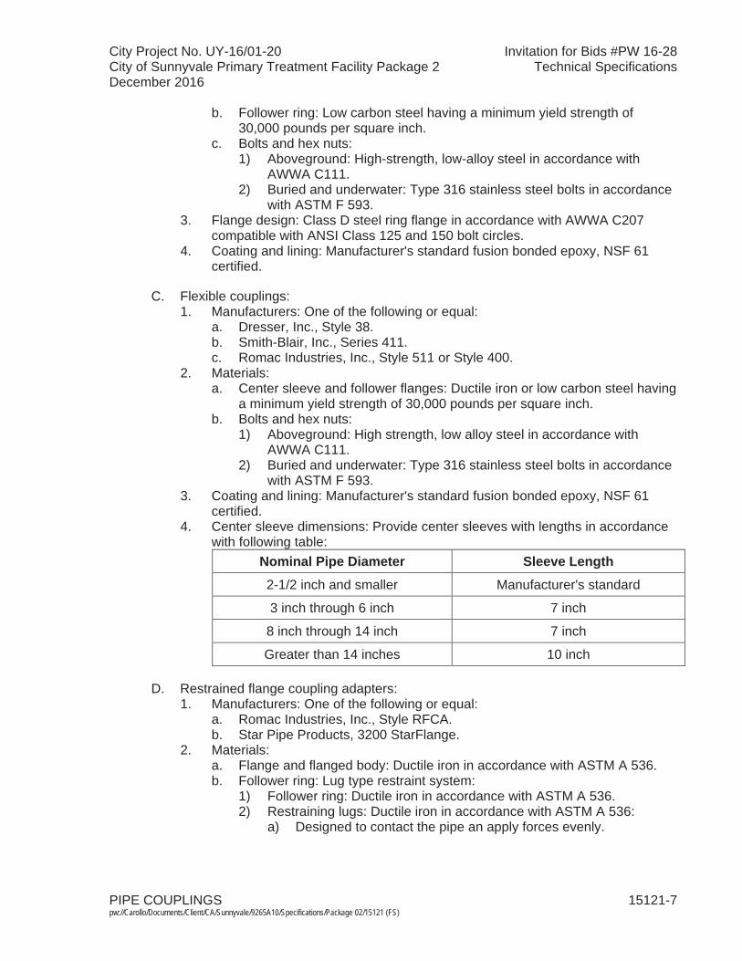
City Project No. UY-16/01-20 Invitation for Bids #PW 16-28City of Sunnyvale Primary Treatment Facility Package 2 Technical SpecificationsDecember 2016
PIPE COUPLINGS 15121-7 pw://Carollo/Documents/Client/CA/Sunnyvale/9265A10/Specifications/Package 02/15121 (FS)
b. Follower ring: Low carbon steel having a minimum yield strength of 30,000 pounds per square inch.
c. Bolts and hex nuts:1) Aboveground: High-strength, low-alloy steel in accordance with
AWWA C111.2) Buried and underwater: Type 316 stainless steel bolts in accordance
with ASTM F 593.3. Flange design: Class D steel ring flange in accordance with AWWA C207
compatible with ANSI Class 125 and 150 bolt circles.4. Coating and lining: Manufacturer's standard fusion bonded epoxy, NSF 61
certified.
C. Flexible couplings:1. Manufacturers: One of the following or equal:
a. Dresser, Inc., Style 38.b. Smith-Blair, Inc., Series 411.c. Romac Industries, Inc., Style 511 or Style 400.
2. Materials:a. Center sleeve and follower flanges: Ductile iron or low carbon steel having
a minimum yield strength of 30,000 pounds per square inch.b. Bolts and hex nuts:
1) Aboveground: High strength, low alloy steel in accordance with AWWA C111.
2) Buried and underwater: Type 316 stainless steel bolts in accordance with ASTM F 593.
3. Coating and lining: Manufacturer's standard fusion bonded epoxy, NSF 61 certified.
4. Center sleeve dimensions: Provide center sleeves with lengths in accordance with following table:
Nominal Pipe Diameter Sleeve Length
2-1/2 inch and smaller Manufacturer's standard
3 inch through 6 inch 7 inch
8 inch through 14 inch 7 inch
Greater than 14 inches 10 inch
D. Restrained flange coupling adapters: 1. Manufacturers: One of the following or equal:
a. Romac Industries, Inc., Style RFCA.b. Star Pipe Products, 3200 StarFlange.
2. Materials:a. Flange and flanged body: Ductile iron in accordance with ASTM A 536.b. Follower ring: Lug type restraint system:
1) Follower ring: Ductile iron in accordance with ASTM A 536.2) Restraining lugs: Ductile iron in accordance with ASTM A 536:
a) Designed to contact the pipe an apply forces evenly.
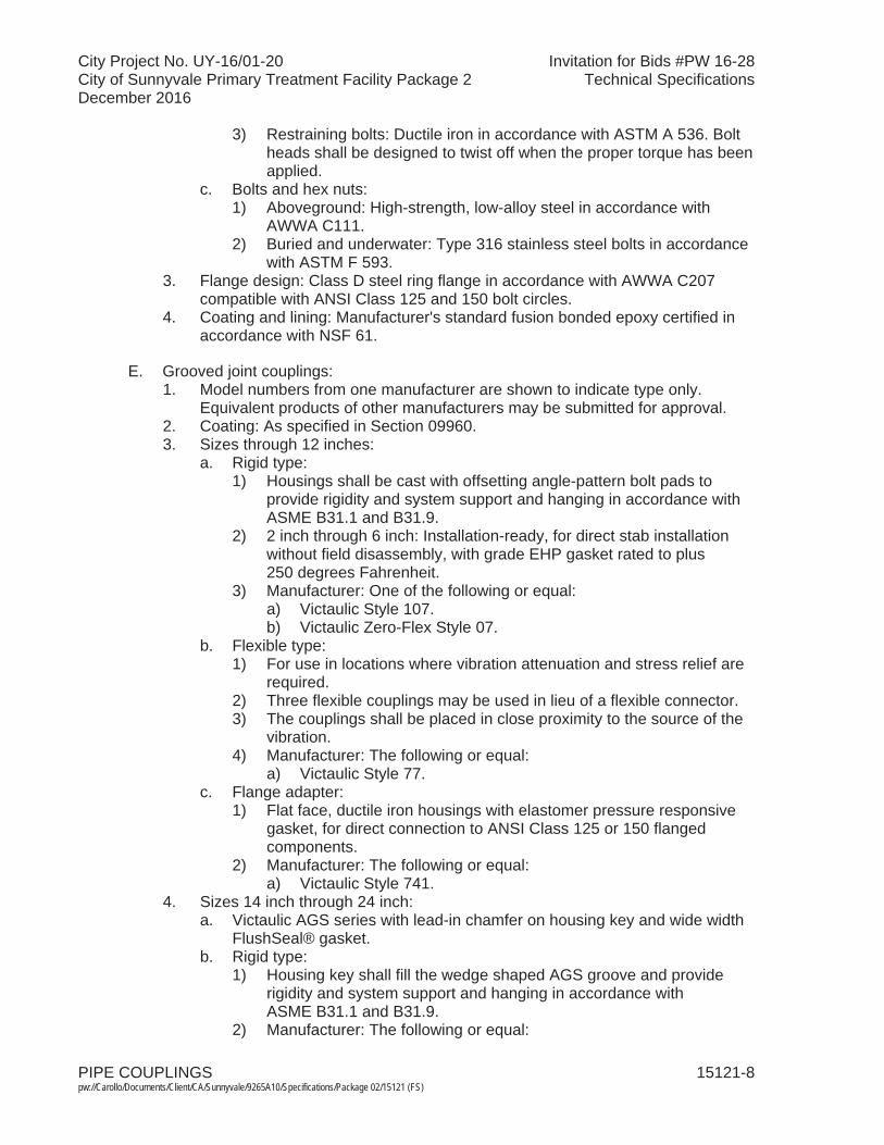
City Project No. UY-16/01-20 Invitation for Bids #PW 16-28City of Sunnyvale Primary Treatment Facility Package 2 Technical SpecificationsDecember 2016
PIPE COUPLINGS 15121-8 pw://Carollo/Documents/Client/CA/Sunnyvale/9265A10/Specifications/Package 02/15121 (FS)
3) Restraining bolts: Ductile iron in accordance with ASTM A 536. Bolt heads shall be designed to twist off when the proper torque has beenapplied.
c. Bolts and hex nuts:1) Aboveground: High-strength, low-alloy steel in accordance with
AWWA C111.2) Buried and underwater: Type 316 stainless steel bolts in accordance
with ASTM F 593.3. Flange design: Class D steel ring flange in accordance with AWWA C207
compatible with ANSI Class 125 and 150 bolt circles.4. Coating and lining: Manufacturer's standard fusion bonded epoxy certified in
accordance with NSF 61.
E. Grooved joint couplings:1. Model numbers from one manufacturer are shown to indicate type only.
Equivalent products of other manufacturers may be submitted for approval.2. Coating: As specified in Section 09960. 3. Sizes through 12 inches:
a. Rigid type:1) Housings shall be cast with offsetting angle-pattern bolt pads to
provide rigidity and system support and hanging in accordance with ASME B31.1 and B31.9.
2) 2 inch through 6 inch: Installation-ready, for direct stab installation without field disassembly, with grade EHP gasket rated to plus 250 degrees Fahrenheit.
3) Manufacturer: One of the following or equal:a) Victaulic Style 107.b) Victaulic Zero-Flex Style 07.
b. Flexible type:1) For use in locations where vibration attenuation and stress relief are
required.2) Three flexible couplings may be used in lieu of a flexible connector.3) The couplings shall be placed in close proximity to the source of the
vibration.4) Manufacturer: The following or equal:
a) Victaulic Style 77.c. Flange adapter:
1) Flat face, ductile iron housings with elastomer pressure responsive gasket, for direct connection to ANSI Class 125 or 150 flanged components.
2) Manufacturer: The following or equal:a) Victaulic Style 741.
4. Sizes 14 inch through 24 inch:a. Victaulic AGS series with lead-in chamfer on housing key and wide width
FlushSeal® gasket.b. Rigid type:
1) Housing key shall fill the wedge shaped AGS groove and provide rigidity and system support and hanging in accordance with ASME B31.1 and B31.9.
2) Manufacturer: The following or equal:

City Project No. UY-16/01-20 Invitation for Bids #PW 16-28City of Sunnyvale Primary Treatment Facility Package 2 Technical SpecificationsDecember 2016
PIPE COUPLINGS 15121-9 pw://Carollo/Documents/Client/CA/Sunnyvale/9265A10/Specifications/Package 02/15121 (FS)
a) Victaulic Style W07.c. Flexible type:
1) Housing key shall fit into the wedge shaped AGS groove and allow for linear and angular pipe movement.
2) Manufacturer: The following or equal:a) Victaulic Style W77.
d. Flange adapter:1) Flat face, ductile iron housings with elastomer pressure responsive
gasket, for direct connection to ANSI Class 125 or 150 flanged components.
2) Manufacturer: The following or equal:a) Victaulic Style W741.
5. For sizes 30 inch and larger:a. Manufacturer: The following or equal:
1) Victaulic Style AGS multiple-segment housing may be used.
2.04 PIPE COUPLINGS FOR STAINLESS STEEL PIPING
A. Flexible couplings:1. Manufacturers: One of the following or equal:
a. Dresser, Inc., Style 38.
B. Grooved joint couplings:1. Manufacturers: One of the following or equal:
a. Victaulic Company.2. Materials:
a. Housings:1) Ductile iron in accordance with ASTM A 536.2) Stainless steel in accordance with ASTM A 351.
b. Gasket: Elastomer in accordance with ASTM D 2000.c. Bolts and nuts:
1) Electroplated steel in accordance with ASTM A 449.2) Stainless steel in accordance with ASTM F 593.
3. Rigid type:a. Victaulic Style 89 and W89 (ductile iron housings). b. Victaulic Style 489 (stainless steel housings).
4. Flexible type: Victaulic Style 77S.
2.05 Transition Couplings
A. For sizes 12 inches and below:1. Manufacturers: One of the following or equal:
a. Romac Style XR5012. Field verify existing pipe material and diameter prior to submittal.3. Provide gaskets for appropriate pipe types and diameters.4. Restrain coupling per requirements of Section 15052.
B. For sizes 12 inches and larger:1. Manufacturers: One of the following or equal:
a. Romac Style RC400 or TC400 Coupling.
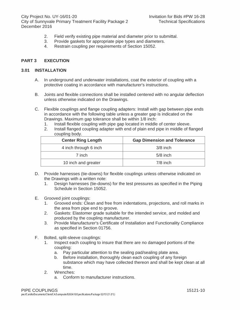
City Project No. UY-16/01-20 Invitation for Bids #PW 16-28City of Sunnyvale Primary Treatment Facility Package 2 Technical SpecificationsDecember 2016
PIPE COUPLINGS 15121-10pw://Carollo/Documents/Client/CA/Sunnyvale/9265A10/Specifications/Package 02/15121 (FS)
2. Field verify existing pipe material and diameter prior to submittal.3. Provide gaskets for appropriate pipe types and diameters.4. Restrain coupling per requirements of Section 15052.
PART 3 EXECUTION
3.01 INSTALLATION
A. In underground and underwater installations, coat the exterior of coupling with a protective coating in accordance with manufacturer's instructions.
B. Joints and flexible connections shall be installed centered with no angular deflection unless otherwise indicated on the Drawings.
C. Flexible couplings and flange coupling adapters: Install with gap between pipe ends in accordance with the following table unless a greater gap is indicated on the Drawings. Maximum gap tolerance shall be within 1/8 inch: 1. Install flexible coupling with pipe gap located in middle of center sleeve.2. Install flanged coupling adapter with end of plain end pipe in middle of flanged
coupling body.Center Ring Length Gap Dimension and Tolerance4 inch through 6 inch 3/8 inch
7 inch 5/8 inch
10 inch and greater 7/8 inch
D. Provide harnesses (tie-downs) for flexible couplings unless otherwise indicated on the Drawings with a written note: 1. Design harnesses (tie-downs) for the test pressures as specified in the Piping
Schedule in Section 15052.
E. Grooved joint couplings:1. Grooved ends: Clean and free from indentations, projections, and roll marks in
the area from pipe end to groove.2. Gaskets: Elastomer grade suitable for the intended service, and molded and
produced by the coupling manufacturer.3. Provide Manufacturer's Certificate of Installation and Functionality Compliance
as specified in Section 01756.
F. Bolted, split-sleeve couplings: 1. Inspect each coupling to insure that there are no damaged portions of the
coupling:a. Pay particular attention to the sealing pad/sealing plate area.b. Before installation, thoroughly clean each coupling of any foreign
substance which may have collected thereon and shall be kept clean at all time.
2. Wrenches: a. Conform to manufacturer instructions.

City Project No. UY-16/01-20 Invitation for Bids #PW 16-28City of Sunnyvale Primary Treatment Facility Package 2 Technical SpecificationsDecember 2016
PIPE COUPLINGS 15121-11pw://Carollo/Documents/Client/CA/Sunnyvale/9265A10/Specifications/Package 02/15121 (FS)
b. Bolts and studs shall be tightened so as to secure a uniform gasket compression between the coupling and the body of the pipe with all bolts or studs tightened approximately the same amount.
c. Final tightening shall be done by hand (no air impact wrenches) and is complete when the coupling is in uniform contact with the outside surface of the pipe all around the circumference of the pipe.
3. No joint shall be misfit in any plane.4. On the fixed ends of bolted, split-sleeve couplings, the shoulders shall bear on
the restraint rings all around with no visible gap.5. Ends of piping where coupler are installed shall be smooth and free of defects:
a. Remove weld splatter and grind smooth.b. Grind pipe seam welds flush with pipe wall and smooth.
3.02 COMMISSIONING AND PROCESS START-UP REQUIREMENTS
A. As specified in Section 01756 and this Section.
B. Manufacturer services from each manufacturer for all valves supplied:1. Provide Manufacturer's Certificate of Source Testing.2. Provide Manufacturer's Certificate of Installation and Functionality Compliance.3. Manufacturer's Representative onsite requirements:
a. Installation: 1 trip, 2 days minimum.b. Functional Testing: 1 trip, 1 day minimum each.
4. Training:a. Maintenance: 4 hours per session, 2 sessions. b. Operation: 4 hours per session, 2 sessions.
5. Process operational period:a. As required by Owner or Contractor.
C. Functional Testing:1. Pressure testing as specified in Sections 15052 and 15956.
END OF SECTION


City Project No. UY-16/01-20 Invitation for Bids #PW 16-28City of Sunnyvale Primary Treatment Facility Package 2 Technical SpecificationsDecember 2016
FIRE HYDRANTS 15122-1 pw://Carollo/Documents/Client/CA/Sunnyvale/9265A10/Specifications/Package 02/15122 (FS)
SECTION 15122
FIRE HYDRANTS
PART 1 GENERAL
1.01 SUMMARY
A. Section includes: Barrel type fire hydrants.
1.02 REFERENCES
A. American Water Works Association (AWWA):1. C 503 - Standard for Wet-Barrel Fire Hydrants. 2. AWWA Manual M-17.
B. City of Sunnyvale Standard Details: 1. Details 2B and 2B-2.
C. City of Sunnyvale Standard Specifications: 1. Sections 207-9.21.1. and 208-7.2.7.
PART 2 PRODUCTS
2.01 MANUFACTURERS
A. Manufacturers: One of the following or equal:1. As listed in the City of Sunnyvale Standard Specifications.
2.02 MATERIALS
A. Fire hydrants:1. Wet barrel in accordance with type AWWA C 503, as complemented and
modified by the City of Sunnyvale Standard Specifications and Standard Details.
2. Provide hydrants with ground level break-off feature and manufactured such that the valve stem will not be bent when the hydrant is damaged or broken at or near the ground level.
3. When shut, provide valves that remain reasonably tight when the upper portion of the barrel is broken off.
4. Diameter of the main valve opening: Not less than 4 inches.5. Inlet connection: 6-inch diameter mechanical joint for ductile iron pipe.6. Provide two 2-1/2-inch hose nozzles and one 4-inch pumper nozzle facing the
street:a. Provide nozzles with hose caps chained to the hydrant barrel.b. Nozzle threads: National standard hose thread.
City Project No. UY-16/01-20 Invitation for Bids #PW 16-28City of Sunnyvale Primary Treatment Facility Package 2 Technical SpecificationsDecember 2016
FIRE HYDRANTS 15122-2 pw://Carollo/Documents/Client/CA/Sunnyvale/9265A10/Specifications/Package 02/15122 (FS)
7. Hydrants: Furnish with drain valve.8. Color of hydrant above ground as required by the City of Sunnyvale Standard
Specifications and Standard Details.
PART 3 EXECUTION
3.01 INSTALLATION
A. Install hydrants according to the AWWA Manual M-17 for the installation of fire hydrants and the requirements of City of Sunnyvale Standard Specifications and Standard Details.
B. Install hydrants with proper extension so that branch pipe to hydrant and supply main are at the same elevation.
C. Attach auxiliary 6-inch gate valves by mechanical joint at 18 inches from the hydrant joint, and attach piping ductile-iron to the supply.
D. Firmly set hydrants on a bed of coarse gravel.
END OF SECTION

City Project No. UY-16/01-20 Invitation for Bids #PW 16-28City of Sunnyvale Primary Treatment Facility Package 2 Technical SpecificationsDecember 2016
STRAINERS 15125-1 pw://Carollo/Documents/Client/CA/Sunnyvale/9265A10/Specifications/Package 02/15125 (FS)
SECTION 15125
STRAINERS
PART 1 GENERAL
1.01 SUMMARY
A. Section includes: Strainers.
B. Related section:1. The Contract Documents are complementary; what is called for by one is as
binding as if called for by all.2. It is the Contractor's responsibility for scheduling and coordinating the Work of
subcontractors, suppliers, and other individuals or entities performing or furnishing any of Contractor's Work.
3. The following Sections are related to the Work described in this Section. This list of Related Sections is provided for convenience only and is not intended to excuse or otherwise diminish the duty of the Contractor to see that the completed Work complies accurately with the Contract Documents:a. Section 01340 - Shop Drawings, Product Data and Samples. b. Section 01756 - Commissioning and Process Start-Up.c. Section 01730 - Operation and Maintenance Data.d. Section 15052 - Common Work Results for General Piping. e. Section 15956 - Piping Systems Testing.
1.02 REFERENCES
A. ASTM International (ASTM):1. A 126 - Standard Specification for Gray Iron Castings for Valves, Flanges, and
Pipe Fittings.2. A 420 - Standard Specification for Piping Fittings of Wrought Carbon Steel and
Alloy Steel for Low-Temperature Service.
B. Society of Automotive Engineers (SAE).
1.03 SUBMITTALS
A. Submit as specified in Section 01340.
B. Product data:1. Shop drawings, detailing dimensions, and materials.2. Installation instructions.
C. Provide vendor operation and maintenance manual as specified in Section 01730: 1. Furnish bound sets of installation, operation, and maintenance instructions for
each type strainer. Include information on valves for mechanically cleaned strainers.

City Project No. UY-16/01-20 Invitation for Bids #PW 16-28City of Sunnyvale Primary Treatment Facility Package 2 Technical SpecificationsDecember 2016
STRAINERS 15125-2 pw://Carollo/Documents/Client/CA/Sunnyvale/9265A10/Specifications/Package 02/15125 (FS)
D. Provide Manufacturer's Certificate of Source Testing as specified in Section 01756.
E. Provide Manufacturer's Certificate of Installation and Functionality Compliance as specified in Section 01756.
PART 2 PRODUCTS
2.01 Y-TYPE STRAINERS
A. Y-type strainers 4 inches and larger in diameter:1. Materials:
a. Bodies: Cast iron or semi-steel.b. Ends: Flanged.c. Screens: Brass or Type 304 stainless steel.
2. Suitable for following minimum pressure conditions:a. Steam service: 250 pounds per square inch gauge.b. Water, oil, and gas service: 200 pounds per square inch gauge.
3. Perforated screens:a. Openings: 0.045 inches.b. Active screen opening to pipe area ratio: 2.8, minimum.c. Free area: 37 percent minimum.
4. Manufacturers: One of the following or equal:a. Armstrong International Inc., Code A1. b. ITT/Hoffman, 460 Series.
B. Y-type strainers less than 4 inches in diameter:1. Materials:
a. Bodies: Cast iron or semi-steel.b. Ends: Flanged or threaded.c. Screen: Brass or Type 304 stainless steel.
2. Suitable for minimum pressure of 250 pounds per square inch gauge.3. Screens: Perforations: 1/32 inch.4. Manufacturers: One of the following or equal:
a. Armstrong, Y-Type Strainer.
2.02 BASKET TYPE STRAINERS
A. Provide basket type strainers single or duplex as indicated on the Drawings.
B. Materials:1. Bodies: Cast iron or cast steel.2. Baskets: Low-zinc bronze or stainless steel.
C. Pressure rating: Where not otherwise indicated on the Drawings, 125 pounds per square inch gauge, minimum.
D. Connections: Threaded or flanged, as required.
City Project No. UY-16/01-20 Invitation for Bids #PW 16-28City of Sunnyvale Primary Treatment Facility Package 2 Technical SpecificationsDecember 2016
STRAINERS 15125-3 pw://Carollo/Documents/Client/CA/Sunnyvale/9265A10/Specifications/Package 02/15125 (FS)
E. Covers:1. For strainers 6 inches and smaller in size, secured by yokes or similar quick
opening devices.2. For strainers larger than 6 inches in size, bolted or hinged and bolted with
slotted washers so that bolts or nuts need not be completely removed to open the strainer.
3. Provide lifting eyes on covers weighing more than 50 pounds.
F. Baskets:1. Screen: Mesh or perforated sheet.2. Openings: Not greater than 3/16 inch.3. Free area: Not less than 30 percent.4. Free area to pipe ratio: Not less than 3.
G. Provide duplex strainers with tapered plug transfer valve or with gate type transfer valves.1. Where action on two valve actuators is required to transfer operation from one
chamber to the other, provide actuators mechanically linked for simultaneous operation.
H. Manufacturers:1. Single basket strainers: One of the following or equal:
a. Fluid Engineering, Series 528B.b. Mueller Steam Specialty.
2. Double basket strainers: One of the following or equal: a. Fluid engineering, Series 534 for sizes 1-1/2 inches to 8 inches, and
Series 424 for sizes 10 inches and larger.b. Mueller Steam Specialty.
3. Basket strainers for chemical service:a. Dual or simplex as indicated on the Drawings; baskets and bodies PVC;
gaskets Viton or EPDM as required for the chemical service; basket mesh size to be specified by the Engineer during shop drawing review.
b. Manufacturer: Hayward.
2.03 Y-TYPE STRAINERS FOR CHEMICAL SERVICE
A. Materials:1. Bodies: PVC or CPVC to match piping material.2. Baskets: PVC or CPVC to match piping material.3. Seals:
a. Suitable for Ferric Chlorine Service.
B. Connections:1. Inlet and Outlet: Union.
C. Screens: Perforations not greater than 1/32 inch.
D. Manufacturers: One of the following, or equal.1. Hayward.2. Asahi-America, Inc.
City Project No. UY-16/01-20 Invitation for Bids #PW 16-28City of Sunnyvale Primary Treatment Facility Package 2 Technical SpecificationsDecember 2016
STRAINERS 15125-4 pw://Carollo/Documents/Client/CA/Sunnyvale/9265A10/Specifications/Package 02/15125 (FS)
PART 3 EXECUTION
3.01 INSTALLATION
A. Install in accordance with the manufacturer's recommendations.
3.02 COMMISSIONING AND PROCESS START-UP REQUIREMENTS
A. As specified in Section 01756 and this Section.
B. Functional Testing:1. Pressure testing as specified in Sections 15052 and 15956.
C. Manufacturer (each) services for each type of strainer: 1. Provide Manufacturer's Certificate of Source Testing.2. Provide Manufacturer's Certificate of Installation and Functionality Compliance.3. Training and other on-site services:
a. Mechanically cleaned only. 4. Manufacturer's Representative onsite requirements:
a. Installation: 1 trip, 2 days minimum.b. Functional Testing: 1 trips, 1 day minimum.
5. Training:a. Maintenance: 2 hours per session, 2 session.b. Operation: 1 hours per session, 2 sessions.
6. Process operational period:a. As required by Owner or Contractor.
END OF SECTION

City Project No. UY-16/01-20 Invitation for Bids #PW 16-28City of Sunnyvale Primary Treatment Facility Package 2 Technical SpecificationsDecember 2016
CAST IRON SOIL PIPE: ASTM A 74 15210-1 pw://Carollo/Documents/Client/CA/Sunnyvale/9265A10/Specifications/Package 02/15210 (FS)
SECTION 15210
CAST IRON SOIL PIPE: ASTM A 74
PART 1 GENERAL
1.01 SUMMARY
A. Section includes: Cast iron soil piping and acid resistant cast iron soil piping.
B. Related sections:1. The Contract Documents are complementary; what is called for by one is as
binding as if called for by all.2. It is the Contractor's responsibility for scheduling and coordinating the Work of
subcontractors, suppliers, and other individuals or entities performing or furnishing any of Contractor's Work.
3. The following Sections are related to the Work described in this Section. This list of Related Sections is provided for convenience only and is not intended to excuse or otherwise diminish the duty of the Contractor to see that the completed Work complies accurately with the Contract Documents:a. Section 01340 - Shop Drawings, Product Data and Samples. b. Section 01756 - Commissioning and Process Start-Up.c. Section 15052 - Common Work Results for General Piping.d. Section 15956 - Piping Systems Testing.
1.02 REFERENCES
A. ASTM International (ASTM):1. A 74 - Standard Specification for Cast Iron Soil Pipe and Fittings.2. A 888 - Standard Specifications for Hubless Cast Iron Soil Pipe and Fittings for
Sanitary and Storm Drain, Waste, and Vent Pipe Applications.3. C 564 - Standard Specification for Rubber Gaskets for Cast Iron Soil Pipe and
Fittings.
1.03 SUBMITTALS
A. Submit as specified in Section 01340.
B. Product data:1. Shop drawings:
a. Joints, fittings, and specials. b. Structural and pipe connections.
2. Gaskets.
C. Layout drawings.
D. Provide installation instructions.

City Project No. UY-16/01-20 Invitation for Bids #PW 16-28City of Sunnyvale Primary Treatment Facility Package 2 Technical SpecificationsDecember 2016
CAST IRON SOIL PIPE: ASTM A 74 15210-2 pw://Carollo/Documents/Client/CA/Sunnyvale/9265A10/Specifications/Package 02/15210 (FS)
E. Provide Manufacturer's Certificate of Source Testing as specified in Section 01756.
F. Provide Manufacturer's Certificate of Installation and Functionality Compliance as specified in Section 01756.
PART 2 PRODUCTS
2.01 MATERIALS
A. Cast iron soil piping, underground:1. Cast iron soil pipe underground: Bell-and-spigot service weight cast iron soil
pipe in accordance with ASTM A 74.2. Make joints by using positive double seal compression type gaskets in
accordance with ASTM C 564.3. Pipe and fittings shall be marked with the collective trademark of the Cast Iron
Soil Pipe Institute.
B. Cast iron soil piping, aboveground:1. Piping: As specified for cast iron soil piping underground, or "No Hub" cast iron
soil pipe and fittings:a. Couplings for no hub cast iron soil piping: Consisting of a stainless steel
corrugated shield and clamp assembly over a molded 1-piece neoprene sealing sleeve, in accordance with ASTM A 888.
2. Threaded joints: American standard taper screw threads, cut clean and made up with Teflon tape or an acceptable paste thread compound applied to the male threads only.
3. Pipe and fittings shall be marked with the collective trademark of the Cast Iron Soil Pipe Institute.
C. Acid resistant cast iron piping:1. Manufacturers: One of the following or equal:
a. The Duriron Company, Inc., Dayton, Ohio.b. Provide substitutes from other manufacturers with same chemical
properties and weight equal or heavier than the weight of Duriron piping.2. Make joints of stainless steel mechanical connectors with Teflon and neoprene
liner, or with rope packing recommended by manufacturer.3. Joints and fittings used for digester gas piping: Split flange type.
2.02 FABRICATION
A. Line cast iron soil pipe and fittings inside and coat outside in accordance with Pipe Schedule in Section 15052.

City Project No. UY-16/01-20 Invitation for Bids #PW 16-28City of Sunnyvale Primary Treatment Facility Package 2 Technical SpecificationsDecember 2016
CAST IRON SOIL PIPE: ASTM A 74 15210-3 pw://Carollo/Documents/Client/CA/Sunnyvale/9265A10/Specifications/Package 02/15210 (FS)
PART 3 EXECUTION
3.01 INSTALLATION
A. Cast iron soil piping:1. Encase in concrete underground cast iron soil piping under structures:
a. Encase pipe as indicated on the Drawings and as scheduled in Section 15052.
2. Support aboveground horizontal cast iron soil piping at not more than 5 foot spacing.
3. Aboveground vertical cast iron soil piping:a. Install vertical piping in chases in the wall where the wall is plastered;
where the wall is not plastered, vertical piping may be installed in chases in the wall or may be run exposed.
b. Support vertical pipes at the base and at each floor.4. Fittings:
a. Make junctions with sanitary tees or with wyes, with brass screw plug cleanouts at accessible locations at changes in direction.
b. Make changes in pipe size with reducing fittings.c. Make changes in direction by use of 45 degree wyes, half wyes, long
sweep 1/4 bends, 1/5, 1/6, 1/8, or 1/16 bends, except that sanitary tees may be used on vertical stacks; short 1/4 bends or elbows 3 inches in size or larger may be used on soil or waste lines where the change in direction of flow is from horizontal to vertical, and on the discharge from water closets.
d. Cleanouts: Same size as the pipe, except that cleanout plugs larger than 4 inches will not be required.
B. Acid-resistant cast iron piping:1. Where rope packing is used, caulk packing into half the depth of the hub:
a. Ram packing well in accordance with manufacturer's published instructions.
b. After ramming, fill the joints with lead and caulk in accordance with the manufacturer's published instructions.
c. Preheat hubs before pouring lead.2. Do not use hemp packing and jute packing for joints of acid-resistant piping.
3.02 COMMISSIONING AND PROCESS START-UP REQUIREMENTS
A. As specified in Section 01756 and this Section.
B. Manufacturer services: 1. Provide Manufacturer's Certificate of Source Testing.2. Provide Manufacturer's Certificate of Installation and Functionality Compliance.
END OF SECTION


City Project No. UY-16/01-20 Invitation for Bids #PW 16-28City of Sunnyvale Primary Treatment Facility Package 2 Technical SpecificationsDecember 2016
DUCTILE IRON PIPE: AWWA C151 15211-1 pw://Carollo/Documents/Client/CA/Sunnyvale/9265A10/Specifications/Package 02/15211 (FS)
SECTION 15211
DUCTILE IRON PIPE: AWWA C151
PART 1 GENERAL
1.01 SUMMARY
A. Section includes: Ductile iron pipe, joints, fittings, gaskets, and pipe linings and coatings.
B. Related sections:1. The Contract Documents are complementary; what is called for by one is as
binding as if called for by all.2. It is the Contractor's responsibility for scheduling and coordinating the Work of
subcontractors, suppliers, and other individuals or entities performing or furnishing any of Contractor's Work.
3. The following Sections are related to the Work described in this Section. This list of Related Sections is provided for convenience only and is not intended to excuse or otherwise diminish the duty of the Contractor to see that the completed Work complies accurately with the Contract Documents:a. Section 01340 - Shop Drawings and Product Data and Samples. b. Section 01756 - Commissioning and Process Start-Up.c. Section 02221 - Trenching, Backfilling, and Compacting for Utilities. d. Section 09960 - High-Performance Coatings.e. Section 13110 - Corrosion Control.f. Section 15052 - Common Work Results for General Piping. g. Section 15110 - Common Work Results for Valves.h. Section 15121 - Pipe Couplings and External Joint Restraints.
1.02 REFERENCES
A. American Society of Mechanical Engineers (ASME):1. B16.1 - Gray Iron Pipe Flanges and Flanged Fittings: Classes 25, 125, and
250.
B. American Water Works Association (AWWA):1. C104 - Standard for Cement-Mortar Lining for Ductile-Iron Pipe and Fittings.2. C105 - Polyethylene Encasement for Ductile-Iron Pipe Systems.3. C110 - Standard for Ductile-Iron and Gray-Iron Fittings.4. C111 - Standard for Rubber-Gasket Joints for Ductile-Iron Pressure Pipe and
Fittings.5. C115 - Flanged Ductile Iron Pipe with Ductile-Iron or Gray-Iron Threaded
Flanges.6. C150 - Standard for Thickness Design of Ductile-Iron Pipe.7. C151 - Standard for Ductile-Iron Pipe, Centrifugally Cast.8. C600 - Installation of Ductile Iron Water Mains and Their Appurtenances.9. C606 - Standard for Grooved and Shouldered Joints.
City Project No. UY-16/01-20 Invitation for Bids #PW 16-28City of Sunnyvale Primary Treatment Facility Package 2 Technical SpecificationsDecember 2016
DUCTILE IRON PIPE: AWWA C151 15211-2 pw://Carollo/Documents/Client/CA/Sunnyvale/9265A10/Specifications/Package 02/15211 (FS)
C. American Welding Society (AWS):1. D11.2 - Guide for Welding Iron Castings.
D. ASTM International (ASTM):1. A 47 - Standard Specifications for Ferritic Malleable Iron Castings.2. A 183 - Standard Specifications for Carbon Steel Track Bolts and Nuts.3. A 536 - Standard Specifications for Ductile Iron Castings.4. C 283 - Standard Test Methods for Resistance of Porcelain Enameled Utensils
to Boiling Acid.5. D 792 - Standard Test Methods for Density and Specific Gravity (Relative
Density) of Plastics by Displacement.
E. Ductile Iron Pipe Research Association (DIPRA):1. Thrust Restraint Design Manual.
F. NACE International (NACE):1. SP0188 - Discontinuity (Holiday) Testing of New Protective Coatings on
Conductive Substrates.
G. National Association of Pipe Fabricators, Inc. (NAPF):1. 500-03 - Surface Preparation Standard for Ductile Iron Pipe and Fittings in
Exposed Locations Receiving Special External Coatings and/or Special Internal Linings.
H. Society for Protective Coatings (SSPC): 1. PA-2 - Measurement of Dry Coating Thickness With Magnetic Gages.
1.03 SYSTEM DESCRIPTION
A. Thrust restraint system design:1. Design restrained joint thrust restraint system.2. Determine the length of pipe that must be restrained on each side of the focus
of a thrust load in accordance with the procedures and criteria established by the DIPRA Thrust Restraint Design Manual as specified in Piping Schedule in Section 15052 and the following additional criteria:a. Design pressure: Test pressure.b. Laying condition: Type 5 in accordance with AWWA C150.c. Soil designation: Silt 1 as defined by DIPRA.d. Unit friction resistance: Based upon plastic tape wrap around of pipe.e. Safety factor: 1.5 (for thrust restraint calculations only).
1.04 SUBMITTALS
A. Submit as specified in Section 01340.
B. Shop Drawings:1. Detailed layout drawings showing alignment of pipes, location of valves,
fittings, and appurtenances, types of joints, connections to structures, and thrust restraint system layouts.
City Project No. UY-16/01-20 Invitation for Bids #PW 16-28City of Sunnyvale Primary Treatment Facility Package 2 Technical SpecificationsDecember 2016
DUCTILE IRON PIPE: AWWA C151 15211-3 pw://Carollo/Documents/Client/CA/Sunnyvale/9265A10/Specifications/Package 02/15211 (FS)
2. Thrust restraint systems: Calculations and layout for restrained joint thrust restraint systems.
3. Photographs, drawings, and descriptions of fittings, gaskets, couplings, grooving of pipe and fittings, pipe linings, and coatings.
C. Provide Manufacturer's Certificate of Source Testing as specified in Section 01756: 1. Manufacturer's test reports for ceramic epoxy and glass lining certifying
successful performance of holiday detection tests:a. This documentation shall identify each piece by mark designation, and
show the actual test results during the final inspection by the manufacturer prior to shipment.
b. Acceptance criteria for glass lining shall be as specified under Field Quality Control.
2. Manufacturer's test results for glass lined pipe-certifying compliance with specified material requirements for glass lining.
3. Include Coating Manufacturer's Technical Representative's reports.4. At the request of the Engineer, perform a maximum of 2 jobsite test
verifications on 12 randomly selected segments per test verification at no additional cost to the Owner.
D. Provide Manufacturer's Certificate of Installation and Functionality Compliance as specified in Section 01756.
1.05 QUALITY ASSURANCE
A. Qualifications:1. Lining manufacturers: For piping specified to receive glass or epoxy lining, use
only a lining manufacturer having a minimum of 5 years' experience supplying this type of product to the wastewater and water industry.
2. Welded on outlets: The pipe manufacturer shall have a minimum of 5 years'experience in the fabrication and testing of outlets of similar size and configuration similar to those used on the Project.
B. Pre-installation meeting:1. Arrange for Coating Manufacturer's Technical Representative to attend
preconstruction conferences, and to make periodic visits to factory or shop to inspect surface preparation of pipe, fittings, and accessories; and to inspect application of linings to interior and coatings to exterior of pipe, fittings, and accessories.
1.06 DELIVERY, STORAGE, AND HANDLING
A. Block piping and associated fittings for shipment to prevent damage to coatings and linings.
B. Carefully handle piping and associated fittings during loading, unloading, and installation:1. Do not drop piping material from cars or trucks.2. Lower piping by mechanical means. 3. Do not drop or pound pipe to fit grade.
City Project No. UY-16/01-20 Invitation for Bids #PW 16-28City of Sunnyvale Primary Treatment Facility Package 2 Technical SpecificationsDecember 2016
DUCTILE IRON PIPE: AWWA C151 15211-4 pw://Carollo/Documents/Client/CA/Sunnyvale/9265A10/Specifications/Package 02/15211 (FS)
C. Ceramic epoxy or Glass lined pipe and fittings must be handled only from the outside:1. No forks, chains, straps, hooks, or other lifting device shall be placed inside
the pipe or fittings for lifting, positioning, or laying.
D. Protect gaskets and polyethylene encasement from long-term exposure to sunlight.
E. Store piping, fittings, and other accessories such that they do not accumulate and hold rainwater, dirt, and debris.
PART 2 PRODUCTS
2.01 MANUFACTURED UNITS
A. Ductile iron piping:1. Typical type:
a. In accordance with AWWA C150 and AWWA C151.b. Pressure class or special thickness class as indicated in the Piping
Schedule provided in Section 15052. 2. Type with screw-on flanges:
a. In accordance with AWWA C115 with minimum special thickness Class 53 wall thickness as required for screw-on flanges.
b. Special thickness class as indicated in the Piping Schedule as specified in Section 15052.
3. Type with grooved couplings:a. Special thickness class as indicated in the Piping Schedule as specified in
Section 15052.
B. Joints:1. Flanged joints:
a. Screw-on flanges: Comply with the diameter, thickness, drilling, and other characteristics in accordance with ASME B16.1. In addition, comply with the following requirements:1) Ductile iron.2) Long hub, threaded, and specially designed for ductile iron pipe.3) After attaching to pipe, machine flange face to make pipe end and
flange even and perpendicular to the axis of the pipe.b. Bolt holes on flanges: 2-holed and aligned at both ends of pipe.c. Cap screw or stud bolt holes: Tapped.d. Bolts and nuts: As specified in Section 15052. e. Gaskets: Standard styrene butadiene copolymer (SBR) unless specified
otherwise in Section 15052. 2. Grooved joints: In accordance with AWWA C606, as complemented and
modified below, radius-cut type, with following components:a. Couplings: Rigid type, cast from ductile iron in accordance with
ASTM A 536, Grade 65-45-12, or malleable iron in accordance with ASTM A 47, Grade 32510.
b. Bolts and nuts: In accordance with ASTM A 183, Grade 2.

City Project No. UY-16/01-20 Invitation for Bids #PW 16-28City of Sunnyvale Primary Treatment Facility Package 2 Technical SpecificationsDecember 2016
DUCTILE IRON PIPE: AWWA C151 15211-5 pw://Carollo/Documents/Client/CA/Sunnyvale/9265A10/Specifications/Package 02/15211 (FS)
c. Gaskets: Capable of being applied on surface of piping with cavities to provide for an improved seal with the internal piping pressure. Material to be used for following services:1) For liquid service: NBR. 2) For air service: Fluoroelastomer.3) For hot water service: EPDM.
d. Fittings: In accordance with AWWA C606, rigid radius-cut groove:1) Center-to-center dimensions: In accordance with AWWA C110.2) Wall thickness and other characteristics: In accordance with
AWWA C606.e. Flanged unit connections: Flanged to grooved joint adapters or a long
enough spool with one end flanged and the other end grooved to prevent interference with the operation of adjacent valves, pumps, or other items.
3. Mechanical joints: In accordance with AWWA C111.4. Push-on rubber gasket joints: In accordance with AWWA C111.5. Integrally restrained mechanical joints:
a. Application:1) Where designation for RMJ, Mech Rest, or restrained mechanical
joints. 2) MJ is specified in the Piping Schedule provided in Section 15052,
supply a restrained mechanical joint piping system, which includes restrained mechanical joints where necessary based upon thrust calculations.
3) Standard mechanical joints as specified above can be used where thrust calculations demonstrate restraint is not required.
b. Design:1) Integral retainer weldment type or lugged type joint with Type 304
stainless steel rods and nuts.2) Restrained mechanical joints of the configuration which utilizes a
gripping or friction force for restraint will not be acceptable.c. Manufacturers: Where restrained mechanical joints are required, use one
of the following or equal:1) American Cast Iron Pipe Company, MJ Coupled Joint.2) Pacific States Cast Iron Pipe Company, Lock Mechanical Joint.3) Griffin Pipe Products Co., Bolt-Lok. 4) Griffin Pipe Products Co., Mech-Lok.
6. Integrally restrained push-on joints:a. Application:
1) Where designation restrained push-on is specified in the Piping Schedule provided in Section 15052, supply a restrained push-onjoint piping system, which includes restrained push-on joints where necessary based upon thrust calculations.
2) Standard push-on rubber gasket joints as specified above can be used where thrust calculations demonstrate restraint is not required.
b. Design:1) Restrained push-on joints of the configuration which utilizes a
gripping or friction force for restraint will not be acceptable.2) Suitable for the following working pressures:
a) For 4- through 24-inch pipe: 350 pounds per square inch gauge.
City Project No. UY-16/01-20 Invitation for Bids #PW 16-28City of Sunnyvale Primary Treatment Facility Package 2 Technical SpecificationsDecember 2016
DUCTILE IRON PIPE: AWWA C151 15211-6 pw://Carollo/Documents/Client/CA/Sunnyvale/9265A10/Specifications/Package 02/15211 (FS)
b) For 30- through 54-inch pipe: 250 pounds per square inch gauge.
c. Manufacturers: One of the following or equal:1) United States Pipe and Foundry Company, TR Flex.2) Pacific States Cast Iron Pipe Company, Thrust Lock.3) American Cast Iron Pipe Company, Flex Ring or Lok-Ring.4) Griffin Pipe Products Co., Snap-Lok.
d. Limit buried joints to half the manufacturer's published allowable angular joint deflection for purposes of pipeline alignment and elimination of fittings.
C. Fittings:1. Ductile iron in accordance with AWWA C110. AWWA C153 fittings are not
permissible. 2. Joint type: Same as that of the associated piping as specified in
Section 15052. 3. Plain end-to-flanged joint connectors using setscrews are not acceptable.
D. Pipe linings: 1. Cement-mortar lining:
a. In accordance with AWWA C104, apply cement-mortar on clean bare metal surfaces. Extend to faces of flanges, ends of spigots, and shoulders of hubs.
b. Minimum lining thickness: Standard in accordance with AWWA C104.c. Type of cement: Type II.
2. Asphaltic seal coat: a. Apply over cement mortar linings and to outside surface of pipes that will
not receive another coating. Apply in accordance with AWWA C151.3. Ceramic epoxy lining:
a. Manufacturers: One of the following or equal:1) PROTECTO 401.2) SP-2000W.
b. Material: Amine cured Novolac epoxy containing at least 20 percent by volume of ceramic quartz pigment.
c. Minimum dry film thickness (DFT): 40 mills.d. Application:
1) The lining shall only be applied by a manufacturer-authorized representative with no less than 5 years of experience in applying the specified material.
2) The application of the lining shall be preformed in accordance with manufacturer's published specifications.
3) Pipe and fittings shall be delivered to application facility with no interior lining.
4) Interior of pipe shall be abrasive blasted per manufacturer'sspecifications.
e. Coverage:1) Gasket and spigot ends-on joints: Provide 6 mils minimum and
10 mils maximum coverage using joint compound as specified by the manufacturer for the gasket area and spigot ends.

City Project No. UY-16/01-20 Invitation for Bids #PW 16-28City of Sunnyvale Primary Treatment Facility Package 2 Technical SpecificationsDecember 2016
DUCTILE IRON PIPE: AWWA C151 15211-7 pw://Carollo/Documents/Client/CA/Sunnyvale/9265A10/Specifications/Package 02/15211 (FS)
2) Mechanical joints: Extend lining from spigot end to edge of gauging ring.
3) Number of coats: As recommended by the lining manufacturer. f. Source quality control:
1) Test pipe and fitting lining with a magnetic film thickness gauge. Perform testing in accordance with the method outlined in SSPC PA-2 Film Thickness Rating.
2) Test lining integrity of pipes using a holiday detection testing instrument set at the voltage as specified by the coating manufacturer:a) Repair all holidays with joint compound in accordance with the
recommendations of the coating manufacturer, and re-test.3) Discard piping or reline piping when pinholes or discontinuities are
found.4. Fusion bonded epoxy:
a. As specified in Section 15110. 5. Glass lining:
a. Manufacturers: One of the following or equal:1) Water Works Manufacturing, Ferrock MEH-32 Lining.2) Vitco Corporation, SG-14 Lining.
b. Material: Special glasses and inorganic materials suited for lining of sewage, sludge, and scum piping with the following characteristics:1) Thickness: 0.008 to 0.012 inch.2) Hardness: 5 to 6 on the Mohs Scale.3) Density: 2.5 to 3.0 grams per cubic centimeter, measured in
accordance with ASTM D 792.4) Thermal shock resistance: Capable of withstanding 350 degrees
Fahrenheit change from 430 degrees Fahrenheit to 80 degrees Fahrenheit without crazing, blistering, or spalling.
5) Gloss retention: Capable of retaining gloss after immersion in an 8 percent sulfuric acid solution at 148 degrees Fahrenheit for10 minutes.
6) Weight loss: Maximum 3 milligrams per square inch when tested in accordance with ASTM C 283.
c. Fabrication:1) Use piping that is suitable for glass lining with minimum Class 53 wall
thickness after application of glass lining.2) Machine interior of pipe. Bore or grit blast in accordance with
NAPF 500-03 prior to application of glass lining.3) Screw factory assembled flanges on pipe, align boltholes, and flange
faces, unless otherwise specified.4) Apply lining to surfaces free of chemicals.5) Place piping in furnaces specially designed for heating piping until
glass melts and fuses with an integral molecular bond to the base metal.
E. Coatings:1. Asphalt varnish: Factory applied.2. Primer:
a. Factory applied for field coating.
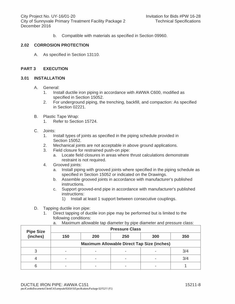
City Project No. UY-16/01-20 Invitation for Bids #PW 16-28City of Sunnyvale Primary Treatment Facility Package 2 Technical SpecificationsDecember 2016
DUCTILE IRON PIPE: AWWA C151 15211-8 pw://Carollo/Documents/Client/CA/Sunnyvale/9265A10/Specifications/Package 02/15211 (FS)
b. Compatible with materials as specified in Section 09960.
2.02 CORROSION PROTECTION
A. As specified in Section 13110.
PART 3 EXECUTION
3.01 INSTALLATION
A. General:1. Install ductile iron piping in accordance with AWWA C600, modified as
specified in Section 15052. 2. For underground piping, the trenching, backfill, and compaction: As specified
in Section 02221.
B. Plastic Tape Wrap:1. Refer to Section 15724.
C. Joints:1. Install types of joints as specified in the piping schedule provided in
Section 15052. 2. Mechanical joints are not acceptable in above ground applications.3. Field closure for restrained push-on pipe:
a. Locate field closures in areas where thrust calculations demonstrate restraint is not required.
4. Grooved joints:a. Install piping with grooved joints where specified in the piping schedule as
specified in Section 15052 or indicated on the Drawings. b. Assemble grooved joints in accordance with manufacturer's published
instructions.c. Support grooved-end pipe in accordance with manufacturer's published
instructions:1) Install at least 1 support between consecutive couplings.
D. Tapping ductile iron pipe:1. Direct tapping of ductile iron pipe may be performed but is limited to the
following conditions:a. Maximum allowable tap diameter by pipe diameter and pressure class:
Pipe Size (inches)
Pressure Class
150 200 250 300 350
Maximum Allowable Direct Tap Size (inches)3 - - - - 3/4
4 - - - - 3/4
6 - - - - 1
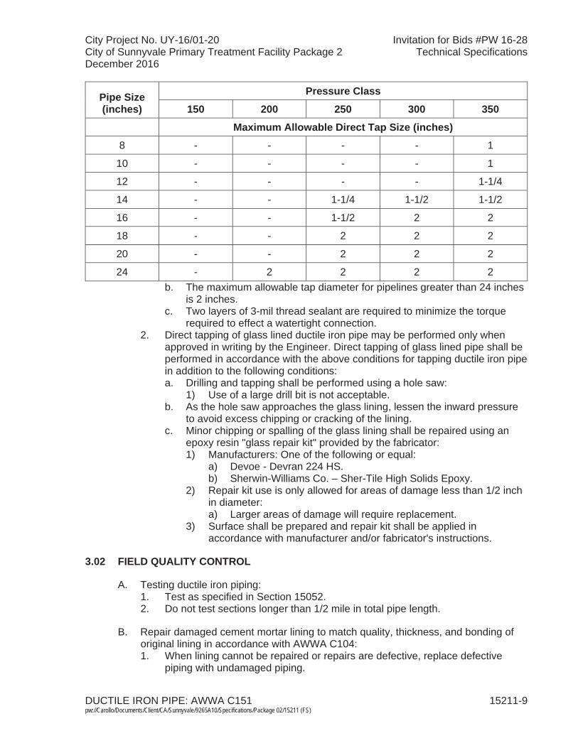
City Project No. UY-16/01-20 Invitation for Bids #PW 16-28City of Sunnyvale Primary Treatment Facility Package 2 Technical SpecificationsDecember 2016
DUCTILE IRON PIPE: AWWA C151 15211-9 pw://Carollo/Documents/Client/CA/Sunnyvale/9265A10/Specifications/Package 02/15211 (FS)
Pipe Size (inches)
Pressure Class
150 200 250 300 350
Maximum Allowable Direct Tap Size (inches)8 - - - - 1
10 - - - - 1
12 - - - - 1-1/4
14 - - 1-1/4 1-1/2 1-1/2
16 - - 1-1/2 2 2
18 - - 2 2 2
20 - - 2 2 2
24 - 2 2 2 2b. The maximum allowable tap diameter for pipelines greater than 24 inches
is 2 inches.c. Two layers of 3-mil thread sealant are required to minimize the torque
required to effect a watertight connection.2. Direct tapping of glass lined ductile iron pipe may be performed only when
approved in writing by the Engineer. Direct tapping of glass lined pipe shall be performed in accordance with the above conditions for tapping ductile iron pipe in addition to the following conditions:a. Drilling and tapping shall be performed using a hole saw:
1) Use of a large drill bit is not acceptable.b. As the hole saw approaches the glass lining, lessen the inward pressure
to avoid excess chipping or cracking of the lining. c. Minor chipping or spalling of the glass lining shall be repaired using an
epoxy resin "glass repair kit" provided by the fabricator:1) Manufacturers: One of the following or equal:
a) Devoe - Devran 224 HS.b) Sherwin-Williams Co. – Sher-Tile High Solids Epoxy.
2) Repair kit use is only allowed for areas of damage less than 1/2 inch in diameter: a) Larger areas of damage will require replacement.
3) Surface shall be prepared and repair kit shall be applied in accordance with manufacturer and/or fabricator's instructions.
3.02 FIELD QUALITY CONTROL
A. Testing ductile iron piping:1. Test as specified in Section 15052. 2. Do not test sections longer than 1/2 mile in total pipe length.
B. Repair damaged cement mortar lining to match quality, thickness, and bonding of original lining in accordance with AWWA C104:1. When lining cannot be repaired or repairs are defective, replace defective
piping with undamaged piping.
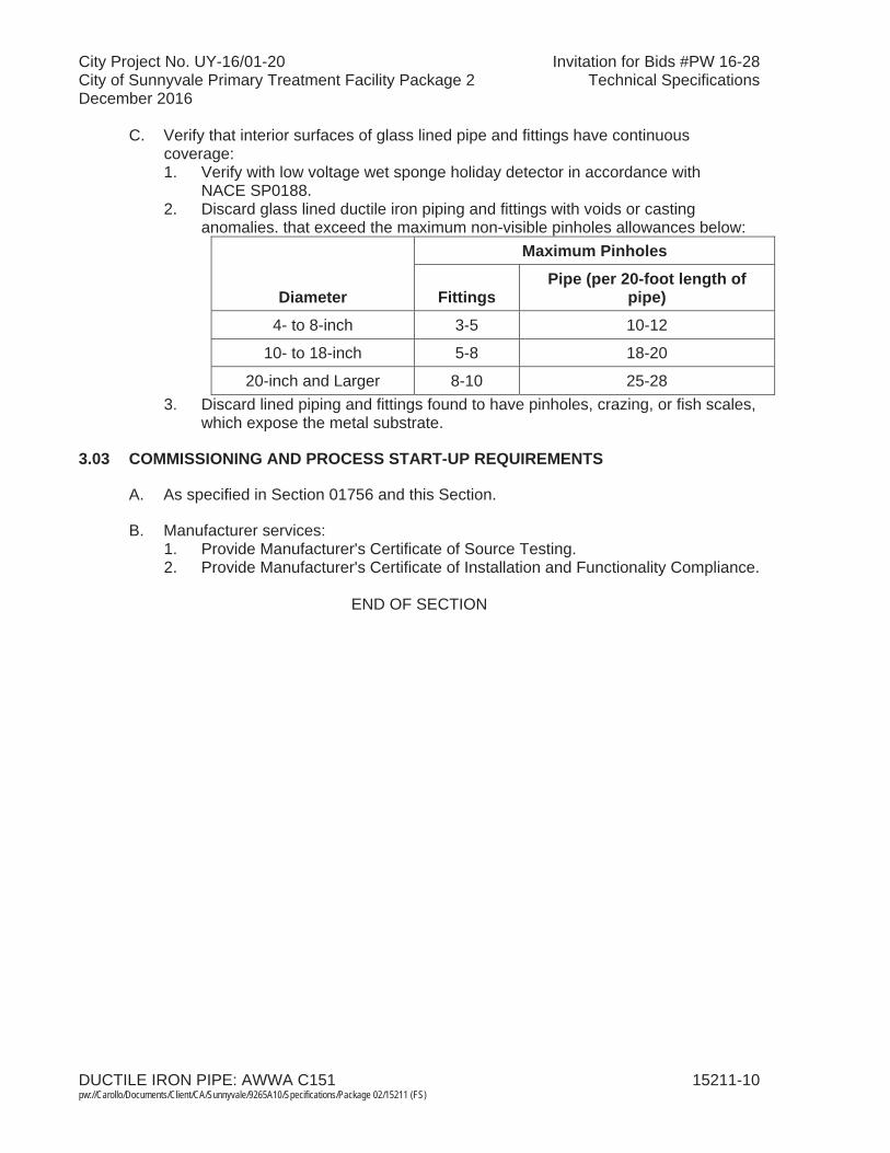
City Project No. UY-16/01-20 Invitation for Bids #PW 16-28City of Sunnyvale Primary Treatment Facility Package 2 Technical SpecificationsDecember 2016
DUCTILE IRON PIPE: AWWA C151 15211-10pw://Carollo/Documents/Client/CA/Sunnyvale/9265A10/Specifications/Package 02/15211 (FS)
C. Verify that interior surfaces of glass lined pipe and fittings have continuous coverage:1. Verify with low voltage wet sponge holiday detector in accordance with
NACE SP0188.2. Discard glass lined ductile iron piping and fittings with voids or casting
anomalies. that exceed the maximum non-visible pinholes allowances below:
Diameter
Maximum Pinholes
FittingsPipe (per 20-foot length of
pipe)
4- to 8-inch 3-5 10-12
10- to 18-inch 5-8 18-20
20-inch and Larger 8-10 25-283. Discard lined piping and fittings found to have pinholes, crazing, or fish scales,
which expose the metal substrate.
3.03 COMMISSIONING AND PROCESS START-UP REQUIREMENTS
A. As specified in Section 01756 and this Section.
B. Manufacturer services: 1. Provide Manufacturer's Certificate of Source Testing.2. Provide Manufacturer's Certificate of Installation and Functionality Compliance.
END OF SECTION
City Project No. UY-16/01-20 Invitation for Bids #PW 16-28City of Sunnyvale Primary Treatment Facility Package 2 Technical SpecificationsDecember 2016
REINFORCED CONCRETE PIPE 15225-1 pw://Carollo/Documents/Client/CA/Sunnyvale/9265A10/Specifications/Package 02/15225 (FS)
SECTION 15225
REINFORCED CONCRETE PIPE
PART 1 GENERAL
1.01 SUMMARY
A. Section includes: Reinforced concrete gravity and low-head pressure pipe, joints, fittings, and specials.
B. Related sections:1. The Contract Documents are complementary; what is called for by one is
as binding as if called for by all.2. It is the Contractor's responsibility for scheduling and coordinating the
Work of subcontractors, suppliers, and other individuals or entities performing or furnishing any of Contractor's Work.
3. The following Sections are related to the Work described in this Section. This list of Related Sections is provided for convenience only and is not intended to excuse or otherwise diminish the duty of the Contractor to see that the completed Work complies accurately with the Contract Documents:a. Section 01340 - Shop Drawings, Product Data and Samples. b. Section 01756 - Commissioning and Process Start-Up.c. Section 02221 - Trenching, Backfilling and Compacting for Utilities. d. Section 09960 - High-Performance Coatings.e. Section 15052 - Common Work Results for General Piping. f. Section 15058 - Plastic Liner for Concrete Pipe.g. Section 15956 - Pipe Systems Testing.
1.02 REFERENCES
A. American Association of State Highway and Transportation Officials (AASHTO):1. Standard Specifications for Highway Bridges.
B. American Water Works Association (AWWA):1. C207 - Standard for Steel Pipe Flanges for Waterworks Service - Sizes
4 Inches Through 144 Inches.2. C300 - Standard for Reinforced Concrete Pressure Pipe, Steel Cylinder
Type.3. C302 - Standard for Reinforced Concrete Pressure Pipe, Non-cylinder
Type. 4. Manual M9 - Concrete Pressure Pipe.
C. ASTM International (ASTM): 1. A 36 - Standard Specification for Carbon Structural Steel.2. A 283 - Standard Specification for Low and Intermediate Tensile Strength
Carbon Steel Plates.

City Project No. UY-16/01-20 Invitation for Bids #PW 16-28City of Sunnyvale Primary Treatment Facility Package 2 Technical SpecificationsDecember 2016
REINFORCED CONCRETE PIPE 15225-2 pw://Carollo/Documents/Client/CA/Sunnyvale/9265A10/Specifications/Package 02/15225 (FS)
3. C 33 - Standard Specifications for Concrete Aggregates.4. C 76 - Standard Specification for Reinforced Concrete Culvert, Storm
Drain, and Sewer Pipe.5. C 150 - Standard Specifications for Portland Cement.6. C 361 - Standard Specification for Reinforced Concrete Low-Head
Pressure Pipe.7. C 443 - Standard Specification for Joints for Concrete Pipe and Manholes,
Using Rubber Gaskets.8. C 497 - Standard Test Methods for Concrete Pipe, Manhole Section, or
Tile.9. C 655 - Standard Specifications for Reinforced Concrete D-Load Culvert,
Storm Drain, and Sewer Pipe.10. D 412 - Standard Test Methods for Vulcanized Rubber and Thermoplastic
Elastomers - Tension.
1.03 SYSTEM DESCRIPTION
A. Design requirements: For reinforced concrete non-cylinder pipe, design pipe, and fittings in accordance with applicable portions of ASTM C 361,AWWA C302, and the following:1. Pressure: The difference between pipe centerline and a hydraulic grade
line elevation, or as indicated in the Pipe Schedule.2. Pipe loads: The delineation of dead loads and live loads used to calculate
stresses in the pipe:a. Earth dead load: The unit weight of compacted backfill used in pipe
load calculations shall be a minimum of 130 pounds per cubic foot, or greater if indicated otherwise in the Piping Schedule.
b. Pipe dead load: The empty weight of pipe including concrete, reinforcing steel, and liner.
c. Water dead load: The added weight to the pipe when full of water.d. Live loads: Unless indicated otherwise in the Piping Schedule, live
loads shall be defined as HS-20 loading in accordance with AASHTO Standard Specifications for Highway Bridges.
e. Pressure: 1) If specified in the Piping Schedule, pressure is the internal design
pressure of the pipe.2) Surge pressure, if specified, is the additional increment of
pressure above the internal design pressure.3. Piping class: As calculated or as indicated in the Piping Schedule in
Section 15052, whichever is higher.4. For gravity RCP less than 48 inches in diameter used for sewers and storm
drainage:a. ASTM C 76 for barrel.b. ASTM C 361 for joint with gasket considerations, as specified in this
Section. c. Smooth bells for joints are disallowed, unless noted otherwise.
5. For gravity RCP greater than 42 inches in diameter used for sewers and storm drainage, and where a specific D-Load pipe design is required as specified in Pipe Schedule:a. ASTM C 655 for barrel.

City Project No. UY-16/01-20 Invitation for Bids #PW 16-28City of Sunnyvale Primary Treatment Facility Package 2 Technical SpecificationsDecember 2016
REINFORCED CONCRETE PIPE 15225-3 pw://Carollo/Documents/Client/CA/Sunnyvale/9265A10/Specifications/Package 02/15225 (FS)
b. ASTM C 361 for joint with gasket considerations, as specified in this Section.
c. Smooth bell for joints are disallowed.6. For low-pressure RCP up to and including 84 inches:
a. ASTM C 361, where pressure head and cover classification is compatible with design condition and/or Pipe Schedule.
b. AWWA C302, where pressure head and/or cover classification exceed tabular classification in accordance with ASTM C 361, or where specified in Pipe Schedule.
c. Perform design calculations as specified in this Section to verify adequacy of concrete and reinforcing-steel requirements for barrel, spigot, and bell area.
7. For low-pressure RCP exceeding 84 inches and up to 144 inches in diameter: a. AWWA C302.b. Perform design calculations as specified in this Section to verify
adequacy of concrete and reinforcing-steel requirements for barrel, spigot, and bell area.
8. Unless indicated otherwise in the Pipe Schedule, bedding condition assumed for earth loads on pipe shall be positive projecting embankment condition; AWWA C302 pipe.
9. Unless indicated otherwise in the Pipe Schedule, stress calculations shall assume a 15-degree bearing bedding condition for pipe dead load and a 90-degree bearing bedding condition for other combined loads; AWWA C302 pipe.
10. D-load, where applicable, shall be the greater value of 1,500 pounds per linear foot per foot of inside pipe diameter, or as calculated to suit pipe placement condition as indicated on the Drawings, or as specified in Pipe Schedule.
11. Minimum wall thickness for ASTM C 76 tabular pipe shall be Wall B.12. Minimum wall thickness for other pipe classifications shall be in
accordance with AWWA C302, Table 4, increased as necessary to address internal pressure or combined loads.
13. Design fitting, specials, and short pipe sections: a. In accordance with AWWA C302, fabricated stiffened steel piping; with
cement-mortar lining and coating.b. Reinforcement, lining, and coating shall be manufactured in
accordance with AWWA Manual M9 as complemented and modified below.1) Design pressure: As specified in Pipe Schedule under Class or
Schedule, and, if not noted, the test pressure.2) Wall thickness of steel fitting and specials: As calculated or
minimum thickness as set forth below, whichever is the greater.Pipe Diameter Steel Thickness
54 inches and smaller 3/8 inchLarger than 54 inches to 72 inches 7/16 inchLarger than 72 inches to 96 inches 1/2 inch
Larger than 96 inches to 120 inches 5/8 inch
City Project No. UY-16/01-20 Invitation for Bids #PW 16-28City of Sunnyvale Primary Treatment Facility Package 2 Technical SpecificationsDecember 2016
REINFORCED CONCRETE PIPE 15225-4 pw://Carollo/Documents/Client/CA/Sunnyvale/9265A10/Specifications/Package 02/15225 (FS)
c. Interior lining: Minimum 1-1/4 inches, or greater as required for placement of PVC liner, if specified.
d. Deflection criteria shall be in accordance with AWWA Manual M9: D2/4000, or 0.02D, whichever is less.
e. E1 shall be 1,200 psi for soil cover 5 to 10 feet; shall be 1,400 psi for soil cover greater than 10 feet.
14. Durometer Hardness of Gasket: ASTM C 361, except as modified in this Section: a. Variation within 3.b. Selected hardness incorporated into joint-design stress analysis.c. Selected hardness compatible with internal working pressure and
external pressures from groundwater, if applicable, and joint type (concrete and/or steel).
d. For jacked pipe, selected hardness compatible to maintain joint integrity during placement in addition to normal service.
15. Joints:a. Unless specifically called for in pipe schedule, reinforced-concrete
smooth bell joints are disallowed.b. RCP pipe as indicated on the Drawings or in Pipe Schedule as
beveled-joint pipe shall use steel Carnegie-type joints with a skirt embedded in concrete core and welded to reinforcing steel or projected bells to maintain the wall thickness or greater over the spigot of the joining pipe. On pipelines 54 inches and larger in diameter, the projected bell shall contain 2 layers hoop of reinforcement steel of equal size or greater than the size of the hoop seal in the pipe to eliminate bell cracking. On smaller sizes, the reinforcement in the bell sections shall be increased in size to prevent bell cracking.
c. Unless specifically called out in Pipe Schedule, minimum and maximum laying length for pipe shall be in accordance with AWWA C302, Section 4.5; with the exception that pipe furnished with concrete joints shall not exceed 16 feet in length for sizes greater than66-inch diameter.
d. In addition to other joint design stress considerations, design joint such that:1) Joint is at least equal in strength to pipe barrel.2) Allowable maximum stress is not exceeded at minimum,
maximum, and nominal joint gap location (Direct Design Pipe).3) Pass proof-of-design test in accordance with ASTM C 497,
Section 13 - Joint Shear Test, with the following exceptions:a) Vertical Test Load F shall be 4,500 pounds per foot of pipe
diameter.b) Cracks that occur during the test load shall not exceed width
of 0.01 inch up to a total load F of 4,000 pounds per foot of pipe diameter.(1) Cracks exceeding width of 0.01 inch with an applied
load exceeding 4,000 pounds per foot diameter up to a total load F of 4,500 pounds per foot diameter must close to less than width of 0.01 inch upon release of load.
City Project No. UY-16/01-20 Invitation for Bids #PW 16-28City of Sunnyvale Primary Treatment Facility Package 2 Technical SpecificationsDecember 2016
REINFORCED CONCRETE PIPE 15225-5 pw://Carollo/Documents/Client/CA/Sunnyvale/9265A10/Specifications/Package 02/15225 (FS)
(2) Failed pipe shall be rejected at place of manufacture and not accepted.
c) Cracks, if occurring, shall be confined to the joint zone defined as a distance of 2 feet-0 inch from spigot and 2 feet-0 inch from bell end.(1) Cracks, if occurring and projecting beyond this defined
joint zone, shall be considered failure to pass the joint shear test.
d) Quantity of shear tests shall be as noted on Pipe Schedule, but in no case less than 1 test for each size class pipe.
e. Pipe placed by insertion in a carrier pipe or direct jacking does not exceed maximum allowable stresses for joint.
f. Pipe furnished with concrete joints shall have a double cage of steel reinforcement extended into the bell with 1 cage located near the interior bell surface.
g. Loading on joint from gasket material shall be assumed at a minimum of 150 pounds force per inch of circumference per gasket face.1) If necessary, increase loading to suit joint design, but in no case
decrease the minimum allowance.h. Gasket styles: Unless noted otherwise in the Pipe Schedule, pipe
sizes exceeding 42 inches shall be furnished with a double-gasket-style joint.1) Joint design provides for additional joint length as required to
facilitate double gasket.2) Testing tube shall extend internally to facilitate testing and shall
be compatible with testing apparatus.3) Joint test pressure for double-gasket joints shall be as specified
in Section 15956. i. Joints on pipe placed in carrier pipe or direct jacking shall be steel
Carnegie-type and smooth-bell, with a skirt embedded in concrete core and welded to steel liner/shell and/or reinforcing steel.
16. RCP placed by insertion in a carrier pipe or by direct jacking shall be special and in accordance with requirements set forth in AWWA C300 for Reinforced Concrete Cylinder Pipe (RCCP).
17. Use of elliptical steel reinforcement cages is disallowed.
1.04 SUBMITTALS
A. Submit as specified in Section 01340.
B. Shop Drawings:1. Layout drawings.2. Joints.3. Fittings and specials.4. Curves and beveled pipe.5. Structure and pipe connections.6. Curing methods.7. Gasket data.
a. Load deformation data including test curves. 8. Proposed method of manufacture.
City Project No. UY-16/01-20 Invitation for Bids #PW 16-28City of Sunnyvale Primary Treatment Facility Package 2 Technical SpecificationsDecember 2016
REINFORCED CONCRETE PIPE 15225-6 pw://Carollo/Documents/Client/CA/Sunnyvale/9265A10/Specifications/Package 02/15225 (FS)
9. Design calculations.10. Proposed method for additional concrete vibration at the top of the pipe
from where spigot is formed.
C. Provide Manufacturer's Certificate of Source Testing as specified in Section 01756. Include:1. Provide supporting data for all physical properties testing in accordance
with ASTM C 76, ASTM C 361, AWWA C302, etc.2. Provide letter report on 3-edge bearing D-load physical test, if test is
required and noted in Pipe Schedule.
D. Provide Manufacturer's Certificate of Installation and Functionality Compliance as specified in Section 01756.
PART 2 PRODUCTS
2.01 MATERIALS
A. Concrete materials for pipe manufacture: 1. Cement: ASTM C 150, Type II, low alkali.2. Aggregates: ASTM C 33 except that total deleterious materials shall not
exceed 3 percent.
B. Steel reinforcement for cages: 1. Steel bar reinforcement, wire, and wire fabric in accordance with
ASTM C 361, Section 6.5.2. Bar reinforcement: Grade 40, 60 steel.
C. Gaskets: ASTM C 361, O-ring synthetic neoprene rubber gaskets, except as follows:1. Tensile strength: Minimum 1,900 psi when tested in accordance with
ASTM D 412.2. Type A shore durometer hardness: As amended in this Section.
D. Joints: Neoprene-rubber-gasket type, capable of sealing joints from either internal or external hydrostatic pressure.1. Fiberglass bell rings or collars are disallowed.2. Smooth-bell-type joints which utilize embedded-steel bell rings and spigots
are disallowed, unless specified otherwise in Pipe Schedule, or as specified in this Section.
E. Fittings and specials:1. Fitting flanges: AWWA C207, Class B. 2. Structure and pipe connections:
a. Concrete pipe to steel pipe or fittings: Welded-steel bell ring of size and shape to fit pipe and fitting ends.
b. Concrete pipe to structure: Steel bell ring cast in structure with gasket(s) for flexible joint as indicated on the Drawings.
c. Typical connections: Carnegie-type joint using O-ring gaskets.

City Project No. UY-16/01-20 Invitation for Bids #PW 16-28City of Sunnyvale Primary Treatment Facility Package 2 Technical SpecificationsDecember 2016
REINFORCED CONCRETE PIPE 15225-7 pw://Carollo/Documents/Client/CA/Sunnyvale/9265A10/Specifications/Package 02/15225 (FS)
d. Steel bell rings: ASTM A 283 or ASTM A 36. e. Bell ring coating: High-solids polyamine epoxy or Amercoat 78 HBB
coal-tar epoxy as specified in Section 09960.
F. Provide plastic liner as specified in Section 15058.
2.02 PRODUCT DESIGN
A. Joints:1. Gaskets:
a. Groove design: 1) In lieu of load deformation data specified, manufacturer shall
have the option of documenting and furnishing data used to support and configure gasket design; such data is in addition to physical testing specified elsewhere.
b. Information on gasket requirements in accordance with ASTM C 361and additional provisions set forth above.1) Address gasket-loading specified in this Section.
2. Bell and spigot:a. Stresses in bells and spigots (Direct Design Pipe).b. Maximum allowable angle of deflection of joint.c. Maximum, minimum, and recommended nominal joint gap.d. Geometry and reinforcement.e. Collars, bands, or other elements designed for reinforcement.f. Gasket containment and bearing surfaces.
B. Pipe materials:1. Comply with the provisions of applicable portions in accordance with
ASTM C 361 and AWWA C302.2. Pipe bedding assumptions and design coefficients.3. Pipe barrel stress analysis based on load and bedding assumptions, in
accordance with AWWA Manual M9.4. Proposed method of manufacture.5. Joint design details.
C. Proposed method for additional concrete vibration at the top of the pipe from where spigot is formed.
2.03 SOURCE QUALITY CONTROL
A. Test all physical properties in accordance with ASTM C 76, ASTM C 361,AWWA C302, etc.
B. Perform calculations confirming the specified design conditions and limitations, including but not necessarily limited to:1. Dead loads (earth, pipe, and water).2. Live loads, including live loads due to construction methodology, if
applicable.3. Internal pressure and surge pressure, if specified.4. Pipe bearing condition.
City Project No. UY-16/01-20 Invitation for Bids #PW 16-28City of Sunnyvale Primary Treatment Facility Package 2 Technical SpecificationsDecember 2016
REINFORCED CONCRETE PIPE 15225-8 pw://Carollo/Documents/Client/CA/Sunnyvale/9265A10/Specifications/Package 02/15225 (FS)
5. Stress analysis for circumferential steel area for pipe and joints at invertand sides for combined loading conditions (Direct Design Pipe).a. Condition 1: A combination of working pressure, dead loads (earth,
pipe, and water), and live loads.b. Condition 2: A combination of dead loads (earth, pipe, and water), live
loads, and zero internal pressure.c. Condition 3: A combination of working pressure, surge pressure (if
specified), and dead loads (earth, pipe, and water).d. Condition 4: Dead load from weight of pipe only (as specified in this
Section).6. Stress analysis on joint and adjacent pipe transferring pipe loads to joint for
following minimum conditions, assuming a free, unsupported bell (Direct Design Pipe):a. Perform normal concentric alignment service.b. Perform eccentric alignment service.c. Perform beginning at insertion of joint.d. Perform at designed joint gap.e. Perform at maximum joint gap.f. Perform at minimum joint gap.
C. If pipe manufacturer is not capable or desirous of using finite element analyses to accomplish the above, perform additional mathematical modeling to determine and ensure adequacy of joint-strength design.
D. Perform at least 1 hydrostatic test on 2 pipes joined together to test a joint for each pipe size.1. When straight pipe joints are deflected to form curves, test a joint with the
maximum deflection with said testing to be in accordance with ASTM C 443.
E. Dye check welds in fittings.
F. Perform 3-edge bearing D-load physical test (external load crushing strength test) in accordance with ASTM C 497, if specified in Piping Schedule.
2.04 FABRICATION
A. Manufacture pipe by the centrifugally spun process (pipe less than 42-inch diameter) and by vertical casting (wet-cast) between stationary inner and outer metal forms (pipe greater than 36 inches in diameter).1. Packer-head type pipe and dry-cast pipe is disallowed.2. Machine-made (dry-cast) pipe may be used as an alternative to
centrifugally spun pipe for ASTM C 76 storm drain pipe 36 inches and less in diameter only.
B. Permissible variations:1. Internal diameter:
a. The roundness of the pipe measured at the bell and spigot (immediately adjacent to the joint groove) of each pipe shall be such
City Project No. UY-16/01-20 Invitation for Bids #PW 16-28City of Sunnyvale Primary Treatment Facility Package 2 Technical SpecificationsDecember 2016
REINFORCED CONCRETE PIPE 15225-9 pw://Carollo/Documents/Client/CA/Sunnyvale/9265A10/Specifications/Package 02/15225 (FS)
that no diameter differs from the mean diameter by more than 0.004D (0.4 percent) or 1/4 inch, whichever is more restrictive.1) The mean diameter shall be the arithmetic mean of
6 measurements referencing the vertical plane beginning at the soffit/invert diameter, thence in 30-degree increments.
b. The roundness of the pipe barrel measured at the diameter shall not exceed within 0.75 percent of the design diameter at any point.
c. Manufacturer shall conform to tighter production standards for roundness, as may be necessary for joint integrity.
C. Comply with other appropriate requirements contained in referenced Specifications to produce desired end product.
PART 3 EXECUTION
3.01 INSTALLATION
A. General: Install pipe as specified in Section 02221, Section 15052, and this Section.
B. Laying pipe: 1. Assemble and join joints in accordance with the manufacturer's published
instructions for the type of joint.2. When assembled, check the position of each rubber gasket with a feeler
gauge.3. Capture rubber gaskets so gaskets cannot be forced out of intended
position because of hydrostatic pressure or forced in when making joints during pipe laying.
C. Installation on straight-way:1. Unless approved otherwise in the shop drawings submittal-approval stage,
pipe joints shall be installed within the following tolerances.a. Concrete joints: Within 1/2 inch from manufacturer's reference mark
on pipe, the center of which references the designed joint point.b. Steel joints: Within 1/4 inch from manufacturer's reference mark on
pipe, the center of which references the designed joint point.c. Manufacturer shall use tighter tolerance if necessary to produce a
testable joint.2. Joint marks:
a. In addition to other pipe markings specified in the Contract Documents, each pipe delivered to the site shall be marked by manufacturer to indicate the designed joint depth required for joint integrity and as tested in the plant hydraulic testing of the pipe and joints, as follows:1) A mark at the tope at centerline.2) A mark at each side at spring line.3) The mark shall be the width of specified joint tolerance, with
middle of mark representing design point.
City Project No. UY-16/01-20 Invitation for Bids #PW 16-28City of Sunnyvale Primary Treatment Facility Package 2 Technical SpecificationsDecember 2016
REINFORCED CONCRETE PIPE 15225-10pw://Carollo/Documents/Client/CA/Sunnyvale/9265A10/Specifications/Package 02/15225 (FS)
4) Failure to place pipe section within tolerance shall be grounds to reject placed pipe regardless of join pressure test.
D. Installation of curves: 1. In general, and where indicated on the Drawings, make horizontal and/or
vertical curves using pipe with beveled joints. Use slight deflections in the joints of straight pipe for other cases.a. Do not exceed 5-degrees total angular deflection at a joint for beveled
pipe or less if recommended by the pipe manufacturer.b. Maximum joint opening: Do not exceed 3/4 inch for 36-inch diameter
pipe and smaller, and 1 inch for pipe larger than 36 inches in diameter, or less if recommended by pipe manufacturer.
2. Where necessary, make short length pipes for curves of shorter radius than can be made with beveled pipe of usual length.
E. Joint cushions: Use protective joint cushions furnished by pipe manufacturer to protect joint and barrel during selected jacking procedures.
3.02 REPAIR
A. Repair damaged pipe in accordance with ASTM C 361 except use epoxy bonding agent to bond mortar to concrete.
3.03 COMMISSIONING AND PROCESS START-UP REQUIREMENTS
A. As specified in Section 01756 and this Section.
B. Manufacturer services: 1. Provide Manufacturer's Certificate of Source Testing.2. Provide Manufacturer's Certificate of Installation and Functionality
Compliance.
END OF SECTION
City Project No. UY-16/01-20 Invitation for Bids #PW 16-28City of Sunnyvale Primary Treatment Facility Package 2 Technical SpecificationsDecember 2016
POLYETHYLENE (PE) PIPE: ASTM D 2513 15234-1 pw://Carollo/Documents/Client/CA/Sunnyvale/9265A10/Specifications/Package 02/15234 (FS)
SECTION 15234
POLYETHYLENE (PE) PIPE: ASTM D 2513
PART 1 GENERAL
1.01 SUMMARY
A. Section includes: ASTM D 2513 polyethylene piping and fittings.
B. Related sections:1. The Contract Documents are complementary; what is called for by one is as
binding as if called for by all.2. It is the Contractor's responsibility for scheduling and coordinating the Work of
subcontractors, suppliers, and other individuals or entities performing or furnishing any of Contractor's Work.
3. The following Sections are related to the Work described in this Section. This list of Related Sections is provided for convenience only and is not intended to excuse or otherwise diminish the duty of the Contractor to see that the completed Work complies accurately with the Contract Documents:a. Section 01340 - Shop Drawings, Product Data and Samples. b. Section 01756 - Commissioning and Process Start-Up.c. Section 15052 - Common Work Results for General Piping. d. Section 15956 - Piping Systems Testing.
1.02 REFERENCES
A. American Water Works Association (AWWA).
B. ASTM International (ASTM):1. D 1248 - Standard Specification for Polyethylene Plastics Extrusion Materials
for Wire and Cable.2. D 2513 - Standard Specification for Polyethylene (PE) Gas Pressure Pipe,
Tubing and Fittings.3. D 2683 - Standard Specification for Socket-Type Polyethylene Fittings for
Outside Diameter-Controlled Polyethylene Pipe and Tubing.4. D 3261 - Standard Specification for Butt Heat Fusion Polyethylene (PE) Plastic
Fittings for Polyethylene (PE) Plastic Pipe and Tubing.5. F 645 - Standard Guide for Selection, Design and Installation of Thermoplastic
Water-Pressure Piping Systems.
1.03 ABBREVIATIONS
A. NPS: Nominal pipe size followed by the size designation.
B. PE: Polyethylene.
C. SDR: Standard dimension ratio; the outside diameter divided by the pipe wall thickness.
City Project No. UY-16/01-20 Invitation for Bids #PW 16-28City of Sunnyvale Primary Treatment Facility Package 2 Technical SpecificationsDecember 2016
POLYETHYLENE (PE) PIPE: ASTM D 2513 15234-2 pw://Carollo/Documents/Client/CA/Sunnyvale/9265A10/Specifications/Package 02/15234 (FS)
1.04 SUBMITTALS
A. Submit as specified in Section 01340.
B. Shop Drawings:1. Product data.2. Manufacturer's Installation Instructions.
C. Provide Manufacturer's Certificate of Source Testing as specified in Section 01756.Include:1. Date of manufacture of pipe for each lot delivered.
D. Provide Manufacturer's Certificate of Installation and Functionality Compliance as specified in Section 01756.
E. Installation equipment including details on fusion machine used to join polyethylene pipe sections.
F. Qualifications of installation crew for use of the fusion machine used for joining polyethylene pipe.
1.05 QUALITY ASSURANCE
A. Fusion machine technician qualifications: 3-year experience in the installation of similar PE piping systems from the same manufacturer.
B. Mark pipe with nominal size, type, class, schedule, or pressure rating, manufacturer and all markings required in accordance with ASTM and AWWA standards.
1.06 DELIVERY, STORAGE, AND HANDLING
A. Protect from sunlight, scoring, and distortion.
B. Do not allow surface temperatures to exceed 120 degrees Fahrenheit.
C. Store and handle as recommended by manufacturer in published instructions.
PART 2 PRODUCTS
2.01 MATERIALS
A. Extruding and molding material:1. Virgin material containing no scrap, regrind, or rework material except where
permitted in the referenced standards.2. Fittings shall be same material as the pipe and of equal or greater pressure
rating.
B. Manufacturers: One of the following or equal:1. DuPont.2. Amsted Industries, Inc., Plexco.
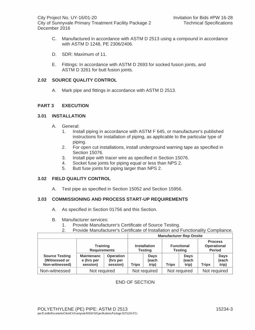
City Project No. UY-16/01-20 Invitation for Bids #PW 16-28City of Sunnyvale Primary Treatment Facility Package 2 Technical SpecificationsDecember 2016
POLYETHYLENE (PE) PIPE: ASTM D 2513 15234-3 pw://Carollo/Documents/Client/CA/Sunnyvale/9265A10/Specifications/Package 02/15234 (FS)
C. Manufactured in accordance with ASTM D 2513 using a compound in accordancewith ASTM D 1248, PE 2306/2406.
D. SDR: Maximum of 11.
E. Fittings: In accordance with ASTM D 2693 for socked fusion joints, and ASTM D 3261 for butt fusion joints.
2.02 SOURCE QUALITY CONTROL
A. Mark pipe and fittings in accordance with ASTM D 2513.
PART 3 EXECUTION
3.01 INSTALLATION
A. General:1. Install piping in accordance with ASTM F 645, or manufacturer's published
instructions for installation of piping, as applicable to the particular type of piping.
2. For open cut installations, install underground warning tape as specified in Section 15076.
3. Install pipe with tracer wire as specified in Section 15076. 4. Socket fuse joints for piping equal or less than NPS 2.5. Butt fuse joints for piping larger than NPS 2.
3.02 FIELD QUALITY CONTROL
A. Test pipe as specified in Section 15052 and Section 15956.
3.03 COMMISSIONING AND PROCESS START-UP REQUIREMENTS
A. As specified in Section 01756 and this Section.
B. Manufacturer services: 1. Provide Manufacturer's Certificate of Source Testing.2. Provide Manufacturer's Certificate of Installation and Functionality Compliance.
Manufacturer Rep Onsite
Source Testing(Witnessed or
Non-witnessed)
TrainingRequirements
InstallationTesting
FunctionalTesting
ProcessOperational
PeriodMaintenance (hrs per session)
Operation (hrs per session) Trips
Days(each trip) Trips
Days(each trip) Trips
Days(each trip)
Non-witnessed Not required Not required Not required Not required
END OF SECTION

City Project No. UY-16/01-20 Invitation for Bids #PW 16-28City of Sunnyvale Primary Treatment Facility Package 2 Technical SpecificationsDecember 2016
POLYVINYL CHLORIDE (PVC) PIPE: AWWA C900 AND C905 15244-1 pw://Carollo/Documents/Client/CA/Sunnyvale/9265A10/Specifications/Package 02/15244 (FS)
SECTION 15244
POLYVINYL CHLORIDE (PVC) PIPE: AWWA C900 AND C905
PART 1 GENERAL
1.01 SUMMARY
A. Section includes:1. AWWA C900 and C905 PVC pipe and fittings.
B. Related sections:1. The Contract Documents are complementary; what is called for by one is as
binding as if called for by all.2. It is the Contractor's responsibility for scheduling and coordinating the Work of
subcontractors, suppliers, and other individuals or entities performing or furnishing any of Contractor's Work.
3. The following Sections are related to the Work described in this Section. This list of Related Sections is provided for convenience only and is not intended to excuse or otherwise diminish the duty of the Contractor to see that the completed Work complies accurately with the Contract Documents:a. Section 01340 - Shop Drawings, Product Data and Samples. b. Section 01756 - Commissioning and Process Start-Up.c. Section 15052 - Common Work Results for General Piping. d. Section 15076 - Pipe Identification. e. Section 15120 - Piping Specialties. f. Section 15211 - Ductile Iron Pipe: AWWA C151. g. Section 15956 - Piping Systems Testing.
1.02 REFERENCES
A. American Water Works Association (AWWA):1. C111 - Standard for Rubber-Gasket Joints for Ductile-Iron Pressure Pipe and
Fittings.2. C605 - Standard for Underground Installation of PVC and PVCO Pressure
Pipe and Fittings for Water.3. C900 - Standard for Polyvinyl Chloride (PVC) Pressure Pipe and Fabricated
Fittings, 4 Inches to 12 Inches, for Water Transmission Distribution.4. M23 – PVC Pipe – Design and Installation Manual.
B. ASTM International (ASTM):1. A 536 - Standard Specification for Ductile Iron Castings. 2. D 1784 - Standard Specification for Rigid Poly(Vinyl Chloride) (PVC)
Compounds and Chlorinated Poly(Vinyl Chloride) (CPVC) Compounds.3. D 3139 - Standard Specification for Joints for Plastic Pressure Pipes Using
Flexible Elastomeric Seals.
City Project No. UY-16/01-20 Invitation for Bids #PW 16-28City of Sunnyvale Primary Treatment Facility Package 2 Technical SpecificationsDecember 2016
POLYVINYL CHLORIDE (PVC) PIPE: AWWA C900 AND C905 15244-2 pw://Carollo/Documents/Client/CA/Sunnyvale/9265A10/Specifications/Package 02/15244 (FS)
4. F 477 - Standard Specification for Elastomeric Seals (Gaskets) for Joining Plastic Pipe.
5. F 645 - Standard Guide for Selection, Design and Installation of Thermoplastic Water-Pressure Piping Systems.
C. NSF International (NSF):1. 61 - Drinking Water System Components - Health Effects.
1.03 ABBREVIATIONS
A. DR: Dimension ratio.
B. NPS: Nominal pipe size followed by the size designation.
1.04 SUBMITTALS
A. Submit as specified in Section 01340.
B. Shop Drawings: 1. Describe materials, pipe, fittings, and gaskets.2. Manufacturer's product handling and installation instructions.
C. Provide Manufacturer's Certificate of Source Testing as specified in Section 01756: 1. Include date of manufacture for each lot delivered.
D. Provide Manufacturer's Certificate of Installation and Functionality Compliance as specified in Section 01756.
1.05 QUALITY ASSURANCE
A. Pipe in potable water applications: Provide pipe bearing NSF 61 seal.
B. Mark plastic pipe with date of extrusion, nominal size, class, manufacturer and all markings required in accordance with ASTM and AWWA standards.
1.06 DELIVERY, STORAGE, AND HANDLING
A. Protect from sunlight, scoring, and distortion.
B. Do not allow surface temperatures to exceed 120 degrees Fahrenheit.
C. Deliver, offload, handle, and store pipe in accordance with manufacturer's or pipe supplier's recommendations and best practices provided by AWWA M23 and AWWA C605, including compliance with minimum recommended bending radius and maximum safe pulling forces for each specific pipe.
City Project No. UY-16/01-20 Invitation for Bids #PW 16-28City of Sunnyvale Primary Treatment Facility Package 2 Technical SpecificationsDecember 2016
POLYVINYL CHLORIDE (PVC) PIPE: AWWA C900 AND C905 15244-3 pw://Carollo/Documents/Client/CA/Sunnyvale/9265A10/Specifications/Package 02/15244 (FS)
PART 2 PRODUCTS
2.01 PIPE
A. General: 1. Extruding and molding material: Virgin material containing no scrap, regrind, or
rework material except where permitted in the referenced standards.2. In accordance with AWWA C900 and C905. 3. Made from a PVC compound conforming to cell classification 12454 in
accordance with ASTM D 1784.4. Pipe used for nonpotable utility water shall have a purple pigment.
B. Pipe:1. Bell and spigot:
a. Pipe with integral bell.b. Pressure Class: 100 psi. c. Manufacturers:
1) Diamond Plastics Corporation. 2) CertainTeed. 3) North American Pipe Corporation.
2.02 FITTINGS
A. Material: 1. Cast or ductile iron fittings as specified in Section 15211, sized for the
dimensions of the pipe being used.2. Provide two layers of polyethylene encasement for all fittings per
Section 15211.
B. Equal to or greater pressure rating than the pipe.
2.03 JOINTS
A. Bell and spigot joints:1. Push-on or mechanical joint type as identified in the Piping Schedule in
Section 15052. 2. Gasketed joint assembly: Meet or exceed the requirements in accordance with
ASTM D 3139. 3. Factory installed gaskets: EPDM in accordance with ASTM F 477.4. Joint restraint at fittings:
a. Concrete thrust blocks are not allowed.b. Mechanical wedge action joint restraints:
1) Manufacturers: One of the following or approved equal:a) EBAA Iron, Inc.:
(1) For pipes 3 to 36 inches: Series 2000PV.(2) For pipes 42 and 48 inches: Series 2200.
b) Star Pipe Products, Series 4000.2) Materials:
a) Gland body: Ductile iron in accordance with ASTM A 536.

City Project No. UY-16/01-20 Invitation for Bids #PW 16-28City of Sunnyvale Primary Treatment Facility Package 2 Technical SpecificationsDecember 2016
POLYVINYL CHLORIDE (PVC) PIPE: AWWA C900 AND C905 15244-4 pw://Carollo/Documents/Client/CA/Sunnyvale/9265A10/Specifications/Package 02/15244 (FS)
b) Wedge and wedge actuating components: Ductile iron inaccordance with ASTM A 536:(1) Wedges: Heat-treated to a minimum of 370 BHN.
c) Actuating bolts and nuts: Ductile iron in accordance with ASTM A 536:(1) Provide torque-limiting twist off components to ensure
proper installation.3) Coatings:
a) Provide a manufacturer applied coating system.b) Manufacturers: One of the following or equal:
(1) EBAA Iron Inc., Mega-Bond.(2) Star Pipe Products, Star-Bond.
4) Consist of multiple gripping wedges incorporated into a follower gland meeting the requirements in accordance with AWWA C111.
5) Allow post assembly angular deflection that is a minimum of 50 percent of the angular deflection allowed by the mechanical joint.
6) Pressure rating equal to or greater than that of the pipe on which it is being used and a minimum safety factor of 2:1 for all sizes.
c. Push-on joint restraint harnesses:1) Manufacturers: One of the following or approved equal:
a) EBAA Iron, Inc.:(1) For pipes 4 to 12 inches: Series 1500.(2) For pipes 14 to 48 inches: Series 2800.
b) Star Pipe Products, Series 4100P.2) Materials:
a) Restraint and backup rings: Ductile iron in accordance with ASTM A 536.
b) Wedge and wedge actuating components: Ductile iron in accordance with ASTM A 536.
c) Tie rods: Low alloy steel in accordance with AWWA C111.3) Coatings:
a) Provide manufacturer applied coating system.b) Manufacturers: One of the following or equal:
(1) EBAA Iron Inc., Mega-Bond.(2) Star Pipe Products, Star-Bond.
4) Consist of a backup ring behind the PVC bell and a restraint ring consisting of multiple gripping wedges connected with number and type of tie rods as recommended by the manufacturer.
5) Allow post assembly angular deflection that is a minimum of 50 percent of the angular deflection allowed by the push-on joint.
6) Pressure rating equal to or greater than that of the pipe on which it is being used and a minimum safety factor of 2:1 for all sizes.
2.04 SOURCE QUALITY CONTROL
A. Bell and spigot piping:1. Hydrostatic proof testing in accordance with AWWA C900: Test pipe and
integral bell to withstand, without failure, 2 times the pressure class of the pipe for a minimum of 5 seconds.
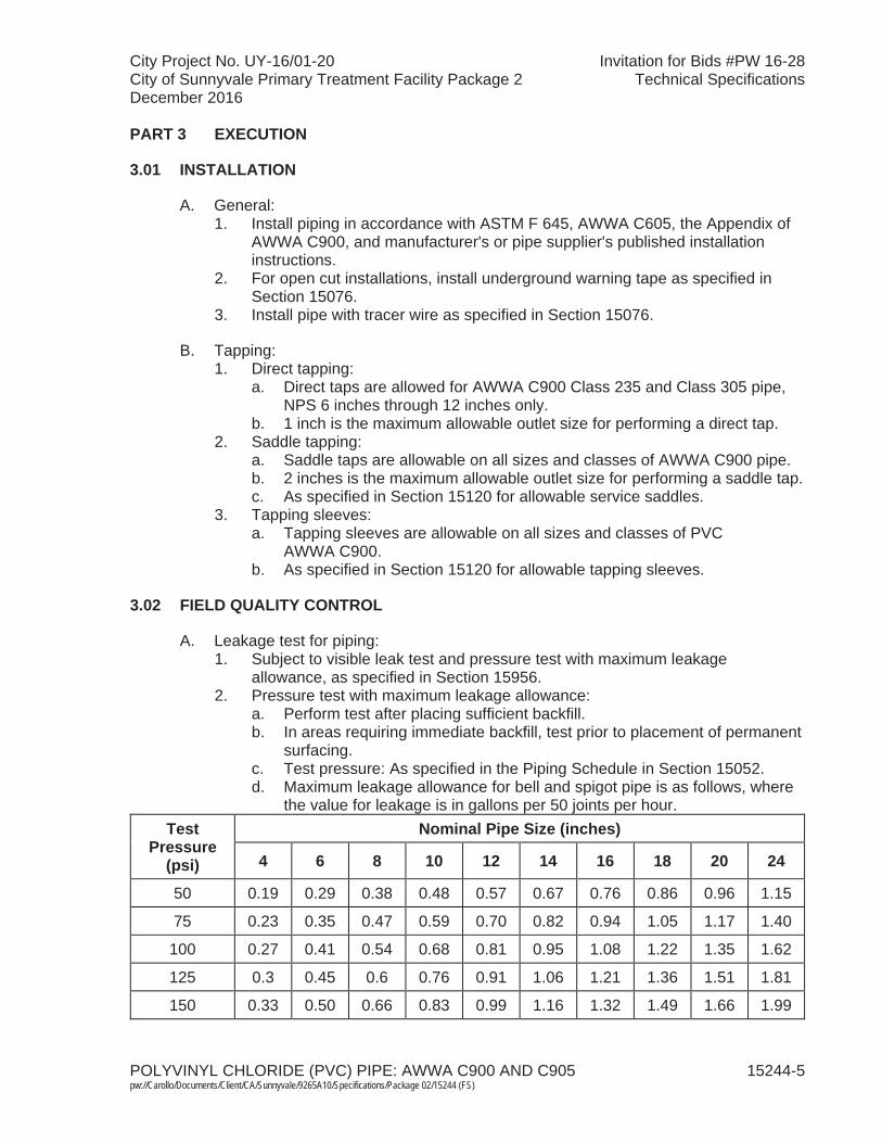
City Project No. UY-16/01-20 Invitation for Bids #PW 16-28City of Sunnyvale Primary Treatment Facility Package 2 Technical SpecificationsDecember 2016
POLYVINYL CHLORIDE (PVC) PIPE: AWWA C900 AND C905 15244-5 pw://Carollo/Documents/Client/CA/Sunnyvale/9265A10/Specifications/Package 02/15244 (FS)
PART 3 EXECUTION
3.01 INSTALLATION
A. General:1. Install piping in accordance with ASTM F 645, AWWA C605, the Appendix of
AWWA C900, and manufacturer's or pipe supplier's published installation instructions.
2. For open cut installations, install underground warning tape as specified in Section 15076.
3. Install pipe with tracer wire as specified in Section 15076.
B. Tapping:1. Direct tapping:
a. Direct taps are allowed for AWWA C900 Class 235 and Class 305 pipe, NPS 6 inches through 12 inches only.
b. 1 inch is the maximum allowable outlet size for performing a direct tap.2. Saddle tapping:
a. Saddle taps are allowable on all sizes and classes of AWWA C900 pipe.b. 2 inches is the maximum allowable outlet size for performing a saddle tap.c. As specified in Section 15120 for allowable service saddles.
3. Tapping sleeves: a. Tapping sleeves are allowable on all sizes and classes of PVC
AWWA C900.b. As specified in Section 15120 for allowable tapping sleeves.
3.02 FIELD QUALITY CONTROL
A. Leakage test for piping: 1. Subject to visible leak test and pressure test with maximum leakage
allowance, as specified in Section 15956. 2. Pressure test with maximum leakage allowance:
a. Perform test after placing sufficient backfill. b. In areas requiring immediate backfill, test prior to placement of permanent
surfacing.c. Test pressure: As specified in the Piping Schedule in Section 15052. d. Maximum leakage allowance for bell and spigot pipe is as follows, where
the value for leakage is in gallons per 50 joints per hour. Test
Pressure (psi)
Nominal Pipe Size (inches)
4 6 8 10 12 14 16 18 20 24
50 0.19 0.29 0.38 0.48 0.57 0.67 0.76 0.86 0.96 1.15
75 0.23 0.35 0.47 0.59 0.70 0.82 0.94 1.05 1.17 1.40
100 0.27 0.41 0.54 0.68 0.81 0.95 1.08 1.22 1.35 1.62
125 0.3 0.45 0.6 0.76 0.91 1.06 1.21 1.36 1.51 1.81
150 0.33 0.50 0.66 0.83 0.99 1.16 1.32 1.49 1.66 1.99

City Project No. UY-16/01-20 Invitation for Bids #PW 16-28City of Sunnyvale Primary Treatment Facility Package 2 Technical SpecificationsDecember 2016
POLYVINYL CHLORIDE (PVC) PIPE: AWWA C900 AND C905 15244-6 pw://Carollo/Documents/Client/CA/Sunnyvale/9265A10/Specifications/Package 02/15244 (FS)
Test Pressure
(psi)
Nominal Pipe Size (inches)
4 6 8 10 12 14 16 18 20 24
175 0.36 0.54 0.72 0.89 1.07 1.25 1.43 1.61 1.79 2.15
200 0.38 0.57 0.76 0.96 1.15 1.34 1.53 1.72 1.91 2.29
225 0.41 0.61 0.81 1.01 1.22 1.42 1.62 1.82 2.03 2.43
250 0.43 0.64 0.85 1.07 1.28 1.50 1.71 1.92 2.14 2.56
275 0.45 0.67 0.90 1.12 1.34 1.57 1.79 2.02 2.24 2.69
300 0.47 0.70 0.94 1.17 1.40 1.64 1.87 2.11 2.34 2.81e. No leakage is allowed for FPVCP.
3.03 COMMISSIONING AND PROCESS START-UP REQUIREMENTS
A. As specified in Section 01756 and this Section.
B. Manufacturer services: 1. Provide Manufacturer's Certificate of Source Testing.2. Provide Manufacturer's Certificate of Installation and Functionality Compliance.
END OF SECTION

City Project No. UY-16/01-20 Invitation for Bids #PW 16-28City of Sunnyvale Primary Treatment Facility Package 2 Technical SpecificationsDecember 2016
POLYVINYL CHLORIDE (PVC) PIPE: SCHEDULE TYPE 15249-1 pw://Carollo/Documents/Client/CA/Sunnyvale/9265A10/Specifications/Package 02/15249 (FS)
SECTION 15249
POLYVINYL CHLORIDE (PVC) PIPE: SCHEDULE TYPE
PART 1 GENERAL
1.01 SUMMARY
A. Section includes: Schedule type PVC pipe and fittings.
B. Related sections:1. The Contract Documents are complementary; what is called for by one is as
binding as if called for by all.2. It is the Contractor's responsibility for scheduling and coordinating the Work of
subcontractors, suppliers, and other individuals or entities performing or furnishing any of Contractor's Work.
3. The following Sections are related to the Work described in this Section. This list of Related Sections is provided for convenience only and is not intended to excuse or otherwise diminish the duty of the Contractor to see that the completed Work complies accurately with the Contract Documents:a. Section 01340 - Shop Drawings, Product Data and Samples. b. Section 01756 - Commissioning and Process Start-Up.c. Section 15052 - Common Work Results for General Process Piping. d. Section 15956 - Piping Systems Testing.
1.02 REFERENCES
A. ASTM International (ASTM):1. D 1784 - Standard Specification for Rigid Poly(Vinyl Chloride) (PVC)
Compounds and Chlorinated Poly(Vinyl Chloride) (CPVC) Compounds.2. D 1785 - Standard Specification for Poly(Vinyl Chloride) (PVC) Plastic Pipe,
Schedules 40, 80 and 120.3. D 2467 - Standard Specification for Poly(Vinyl Chloride) (PVC) Plastic Pipe
Fittings, Schedule 80.4. D 2564 - Standard Specification for Solvent Cements for Poly(Vinyl Chloride)
(PVC) Plastic Piping Systems.5. D 2855 - Standard Practice for Making Solvent-Cemented Joints with Poly
(Vinyl Chloride) (PVC) Pipe and Fittings.6. F 645 - Standard Guide for Selection, Design, and Installation of
Thermoplastic Water-Pressure Piping Systems.
B. NSF International (NSF): 1. 61 - Drinking Water System Components – Health Effects.
1.03 SUBMITTALS
A. Submit as specified in Section 01340.
City Project No. UY-16/01-20 Invitation for Bids #PW 16-28City of Sunnyvale Primary Treatment Facility Package 2 Technical SpecificationsDecember 2016
POLYVINYL CHLORIDE (PVC) PIPE: SCHEDULE TYPE 15249-2 pw://Carollo/Documents/Client/CA/Sunnyvale/9265A10/Specifications/Package 02/15249 (FS)
B. Shop Drawings:1. Describe materials, pipe, fittings, gaskets, and solvent cement.2. Installation instructions.
C. Provide Manufacturer's Certificate of Source Testing as specified in Section 01756.Include as applicable:1. Date of manufacture of tubing for each lot delivered.2. Solvent cement manufacturer's report and certification.
D. Provide Manufacturer's Certificate of Installation and Functionality Compliance as specified in Section 01756.
1.04 QUALITY ASSURANCE
A. Pipe in potable water applications: Provide pipe bearing NSF 61 seal.
B. Mark pipe and fittings in accordance with ASTM D 1785.
1.05 DELIVERY, STORAGE, AND HANDLING
A. Protect from sunlight, scoring, and distortion.
B. Do not allow surface temperatures to exceed 120 degrees Fahrenheit.
C. Store and handle as recommended by manufacturer in published instructions.
PART 2 PRODUCTS
2.01 MATERIALS
A. Extruding and molding material: Virgin material containing no scrap, regrind, or rework material except where permitted in the referenced standards:1. Pipe: Designation PVC 1120 in accordance with ASTM D 1785 and
appendices: a. Extruded from Type I, Grade 1, Class 12454-B material in accordance
with ASTM D 1784.b. Schedule 80 unless otherwise indicated on the Drawings or specified in
the Piping Schedule in Section 15052. c. Provide purple pigment for pipe used in non-potable utility water piping.
2. Fittings: In accordance with ASTM D 2467: a. Same material as the pipe and of equal or greater pressure rating. b. Supplied by pipe manufacturer.c. Unions 2-1/2 inches and smaller:
1) Use socket end screwed unions.d. Unions 3 inches and larger:
1) Use socket flanges with 1/8-inch full-face soft EPDM gasket.3. Solvent cement:
a. In accordance with ASTM D 2564.
City Project No. UY-16/01-20 Invitation for Bids #PW 16-28City of Sunnyvale Primary Treatment Facility Package 2 Technical SpecificationsDecember 2016
POLYVINYL CHLORIDE (PVC) PIPE: SCHEDULE TYPE 15249-3 pw://Carollo/Documents/Client/CA/Sunnyvale/9265A10/Specifications/Package 02/15249 (FS)
b. Manufacturers: The following or equal: 1) IPS Corporation.
c. Certified by the manufacturer for the service of the pipe.d. In potable water applications: Provide solvent cement listed by NSF for
potable water applications.e. Primer: As recommended by the solvent cement manufacturer.
2.02 SOURCE QUALITY CONTROL
A. Meets or exceeds all quality assurance test requirements stated in ASTM D 1785.
PART 3 EXECUTION
3.01 INSTALLATION
A. Install piping in accordance with ASTM F 645, or manufacturer's published instructions for installation of piping, as applicable.
B. Provide molded transition fittings for transitions from plastic to metal pipe:1. Do not thread pipe.
C. Locate unions where indicated on the Drawings, and elsewhere where required for adequate access and assembly of the piping system.
D. Provide serrated nipples for transition from pipe to rubber hose.
E. Solvent weld joints in accordance with ASTM D 2855.
3.02 FIELD QUALITY CONTROL
A. Test pipe as specified in Section 15052 and Section 15956.
3.03 COMMISSIONING AND PROCESS START-UP REQUIREMENTS
A. As specified in Section 01756 and this Section.
B. Manufacturer services: 1. Provide Manufacturer's Certificate of Source Testing.2. Provide Manufacturer's Certificate of Installation and Functionality Compliance.
END OF SECTION

City Project No. UY-16/01-20 Invitation for Bids #PW 16-28City of Sunnyvale Primary Treatment Facility Package 2 Technical SpecificationsDecember 2016
CHLORINATED POLYVINYL CHLORIDE (CPVC) PIPE: ASTM F 441 15259-1 pw://Carollo/Documents/Client/CA/Sunnyvale/9265A10/Specifications/Package 02/15259 (FS)
SECTION 15259
CHLORINATED POLYVINYL CHLORIDE (CPVC) PIPE: ASTM F 441
PART 1 GENERAL
1.01 SUMMARY
A. Section includes: ASTM F 441 CPVC pipe and fittings.
B. Related sections:1. The Contract Documents are complementary; what is called for by one is as
binding as if called for by all.2. It is the Contractor's responsibility for scheduling and coordinating the Work of
subcontractors, suppliers, and other individuals or entities performing or furnishing any of Contractor's Work.
3. The following Sections are related to the Work described in this Section. This list of Related Sections is provided for convenience only and is not intended to excuse or otherwise diminish the duty of the Contractor to see that the completed Work complies accurately with the Contract Documents:a. Section 01340 - Shop Drawings, Product Data and Samples. b. Section 01756 - Commissioning and Process Start-Up.c. Section 15052 - Common Work Results for General Piping. d. Section 15956 - Piping Systems Testing.
1.02 REFERENCES
A. American Water Works Association (AWWA).
B. ASTM International (ASTM):1. D 1784 - Standard Specification for Rigid Poly (Vinyl Chloride) (PVC)
Compounds and Chlorinated Poly (Vinyl Chloride) (CPVC) Compounds.2. F 438 - Standard Specification for Socket-Type Chlorinated Poly (Vinyl
Chloride) (CPVC) Plastic Pipe Fittings, Schedule 40.3. F 439 - Standard Specification for Chlorinated Poly (Vinyl Chloride) (CPVC)
Plastic Pipe Fittings, Schedule 80.4. F 441 - Standard Specification for Chlorinated Poly (Vinyl Chloride) (CPVC)
Plastic Pipe, Schedules 40 and 80.5. F 493 - Standard Specification for Solvent Cements for Chlorinated Poly (Vinyl
Chloride) (CPVC) Plastic Pipe and Fittings.6. F 645 - Standard Guide for Selection, Design, and Installation of
Thermoplastic Water-Pressure Piping Systems.
C. NSF International (NSF).
1.03 ABBREVIATIONS
A. CPVC: Chlorinated polyvinyl chloride.

City Project No. UY-16/01-20 Invitation for Bids #PW 16-28City of Sunnyvale Primary Treatment Facility Package 2 Technical SpecificationsDecember 2016
CHLORINATED POLYVINYL CHLORIDE (CPVC) PIPE: ASTM F 441 15259-2 pw://Carollo/Documents/Client/CA/Sunnyvale/9265A10/Specifications/Package 02/15259 (FS)
1.04 SUBMITTALS
A. Submit as specified in Section 01340.
B. Shop Drawings:1. Describe materials, pipe, fittings, gaskets, and solvent cement.2. Installation instructions.
C. Provide Manufacturer's Certificate of Source Testing as specified in Section 01756.Include:1. Date of manufacture of pipe for each lot delivered.2. Solvent cement manufacturer's report and certification.
D. Provide Manufacturer's Certificate of Installation and Functionality Compliance as specified in Section 01756.
1.05 QUALITY ASSURANCE
A. Pipe in potable water applications: Provide pipe bearing NSF seal.
B. Mark pipe with nominal size, type, class, schedule, or pressure rating, manufacturer and all markings required in accordance with ASTM and AWWA standards.
1.06 DELIVERY, STORAGE, AND HANDLING
A. Protect from sunlight, scoring, and distortion.
B. Do not allow surface temperatures to exceed 120 degrees Fahrenheit.
C. Store and handle as recommended by manufacturer in published instructions.
PART 2 PRODUCTS
2.01 MATERIALS
A. Extruding and molding material: Virgin material containing no scrap, regrind, or rework material except where permitted in the referenced standards.
B. Pipe:1. In accordance with ASTM F 441 and Appendix, CPVC 4120.2. Extruded from Type IV, Grade 1, Class 23447 material in accordance with
ASTM D 1784.3. Schedule 80, unless otherwise indicated on the Drawings or specified in the
Piping Schedule in Section 15052. 4. Manufacturers: One of the following or equal:
a. Charlotte Pipe and Foundry Company.b. Eslon Thermoplastics, Inc.c. GF Harvel.d. Spears Manufacturing Company. e. Chemtrol.
City Project No. UY-16/01-20 Invitation for Bids #PW 16-28City of Sunnyvale Primary Treatment Facility Package 2 Technical SpecificationsDecember 2016
CHLORINATED POLYVINYL CHLORIDE (CPVC) PIPE: ASTM F 441 15259-3 pw://Carollo/Documents/Client/CA/Sunnyvale/9265A10/Specifications/Package 02/15259 (FS)
C. Fittings:1. In accordance with ASTM F 438 or ASTM F 439 for pressure fittings, as
appropriate to the service and pressure requirement.2. Same material as the pipe and of equal or greater pressure rating.3. Supplied by pipe manufacturer.
D. Solvent cement:1. In accordance with ASTM F 493.2. Manufacturers: The following or equal:
a. IPS Corporation.3. Certified by the manufacturer for the service of the pipe.4. Primer: As recommended by the solvent cement manufacturer.
E. Unions 2-1/2 inches and smaller:1. Socket end screwed unions.
F. Unions 3 inches and larger: 1. Socket flanges with 1/8-inch full-face soft EPDM gasket.
2.02 SOURCE QUALITY CONTROL
A. Mark pipe and fittings in accordance with ASTM F 441.
PART 3 EXECUTION
3.01 INSTALLATION
A. General:1. Install piping in accordance with ASTM F 645, or manufacturer's published
instructions for installation of piping, as applicable to the particular type of piping.
2. Provide molded transition fittings for transitions from plastic to metal or IPS pipe:a. Do not thread pipe.
3. Locate unions where indicated on the Drawings, and elsewhere where required for adequate access and assembly of the piping system.
4. Provide serrated nipples for transition from plastic pipe to rubber hose.
B. Installation of piping:1. Clean dirt and moisture from pipe and fittings.2. Bevel pipe ends in accordance with manufacturer's instructions with
chamfering tool or file:a. Remove burrs.
3. Use solvent cement and primer formulated for CPVC.4. Use primer on pressure and non-pressure joints.5. Do not solvent weld joints when ambient temperatures are below 40 degrees
Fahrenheit or above 90 degrees Fahrenheit unless solvent cements specially formulated for these conditions are utilized.
City Project No. UY-16/01-20 Invitation for Bids #PW 16-28City of Sunnyvale Primary Treatment Facility Package 2 Technical SpecificationsDecember 2016
CHLORINATED POLYVINYL CHLORIDE (CPVC) PIPE: ASTM F 441 15259-4 pw://Carollo/Documents/Client/CA/Sunnyvale/9265A10/Specifications/Package 02/15259 (FS)
3.02 FIELD QUALITY CONTROL
A. Test as specified in Section 15052 and Section 15956.
3.03 COMMISSIONING AND PROCESS START-UP REQUIREMENTS
A. As specified in Section 01756 and this Section.
B. Manufacturer services: 1. Provide Manufacturer's Certificate of Source Testing.2. Provide Manufacturer's Certificate of Installation and Functionality Compliance.
END OF SECTION
City Project No. UY-16/01-20 Invitation for Bids #PW 16-28City of Sunnyvale Primary Treatment Facility Package 2 Technical SpecificationsDecember 2016
STEEL PIPE: GALVANIZED AND BLACK, ASTM A 53 15270-1 pw://Carollo/Documents/Client/CA/Sunnyvale/9265A10/Specifications/Package 02/15270 (FS)
SECTION 15270
STEEL PIPE: GALVANIZED AND BLACK, ASTM A 53
PART 1 GENERAL
1.01 SUMMARY
A. Section includes: Steel pipe: Galvanized and black, ASTM A 53.
B. Related sections:1. The Contract Documents are complementary; what is called for by one is as
binding as if called for by all.2. It is the Contractor's responsibility for scheduling and coordinating the Work of
subcontractors, suppliers, and other individuals or entities performing or furnishing any of Contractor's Work.
3. The following Sections are related to the Work described in this Section. This list of Related Sections is provided for convenience only and is not intended to excuse or otherwise diminish the duty of the Contractor to see that the completed Work complies accurately with the Contract Documents:a. Section 01340 - Shop Drawings, Product Data and Samples. b. Section 01756 - Commissioning and Process Start-Up.c. Section 09960 - High-Performance Coatings.d. Section 15052 - Common Work Results for General Piping. e. Section 15110 - Common Work Results for Valves. f. Section 15274 - Plastic Tape Wrap for Pipe.
1.02 REFERENCES
A. American Society of Mechanical Engineers (ASME):1. B16.3 - Malleable-Iron Threaded Fittings: Classes 150 and 300.2. B16.5 - Pipe Flanges and Flanged Fittings.3. B16.9 - Factory-Made Wrought Buttwelding Fittings.4. B16.11 - Forged Fittings, Socket-Welding and Threaded.
B. American Water Works Association (AWWA):1. C200 - Steel Water Pipe - 6 Inches and Larger.2. C203 - Coal-Tar Protective Coatings and Linings for Steel Water Pipelines-
Enamel and Tape-Hot Applied.3. C205 - Standard for Cement-Mortar Protective Lining and Coating for Steel
Water Pipe-4 Inches and Larger-Shop Applied.4. C206 - Field Welding of Steel Water Pipe.5. C207 - Standard for Steel Pipe Flanges for Waterworks Service-Sizes 4 inches
Through 144 inches.6. C602 - Standard for Cement-Mortar Lining of Water Pipelines in Place-
4 inches and Larger.7. C606 - Standard for Grooved and Shouldered Joints.
City Project No. UY-16/01-20 Invitation for Bids #PW 16-28City of Sunnyvale Primary Treatment Facility Package 2 Technical SpecificationsDecember 2016
STEEL PIPE: GALVANIZED AND BLACK, ASTM A 53 15270-2 pw://Carollo/Documents/Client/CA/Sunnyvale/9265A10/Specifications/Package 02/15270 (FS)
C. ASTM International (ASTM):1. A 47 - Standard Specification for Ferritic Malleable Iron Casting.2. A 53 - Standard Specification for Pipe, Steel, Black and Hot-Dipped,
Zinc-Coated, Welded and Seamless.3. A 105 - Standard Specification for Carbon Steel Forgings for Piping
Applications.4. A 153 - Standard Specification for Zinc Coating (Hot-Dip) on Iron and Steel
Hardware.5. A 183 - Standard Specification for Carbon Steel Track Bolts and Nuts.6. A 536 - Standard Specification for Ductile Iron Castings.7. C 150 - Standard Specification for Portland Cement.8. D 429 - Standard Test Methods for Rubber Property-Adhesion to Rigid
Substrates.9. D 2000 - Standard Classification System for Rubber Products in Automotive
Applications.
1.03 SUBMITTALS
A. Submit as specified in Section 01340.
B. Shop Drawings, as appropriate include:1. Details of fittings and specials showing thickness and dimensions of plates.2. Detail of welds and materials.3. Listing of proposed services and locations for use of grooved joint type piping.4. Tabulated layout schedules for cement-mortar lined and coated steel pipe.5. Grooved joint piping fittings, gaskets, couplings.6. Grooving of pipe and fittings. 7. Pipe lining and coating.
C. Provide methods and procedures for pickling of pipe where specified in Section 15052.
D. Provide Manufacturer's Certificate of Source Testing as specified in Section 01756.Include:1. Mill certificates.2. Test reports on gaskets.
E. Provide Manufacturer's Certificate of Installation and Functionality Compliance as specified in Section 01756.
PART 2 PRODUCTS
2.01 MATERIALS
A. Portland cement: In accordance with ASTM C 150, Type II, low alkali.
City Project No. UY-16/01-20 Invitation for Bids #PW 16-28City of Sunnyvale Primary Treatment Facility Package 2 Technical SpecificationsDecember 2016
STEEL PIPE: GALVANIZED AND BLACK, ASTM A 53 15270-3 pw://Carollo/Documents/Client/CA/Sunnyvale/9265A10/Specifications/Package 02/15270 (FS)
2.02 MANUFACTURED UNITS
A. Steel pipe:1. General:
a. In accordance with ASTM A 53:1) Type: Type E - electric-resistance welded or Type S - seamless. 2) Grade: Grade A or B.
b. Schedule:1) As indicated on the Drawings or as specified in Section 15052 pipe
schedule.2) Minimum Schedule unless otherwise indicated on the Drawings or as
specified in Section 15052 pipe schedule:a) Pipe 6 inches and smaller: Schedule 40.b) Pipe greater than 6 inch to 12 inch: Schedule 20.c) Pipe greater than 12-inch: 0.25 inches.
B. Pipe fittings:1. Flanged and welding fittings:
a. Butt -welding fittings in accordance with ASME B16.9. Schedule of fittings: same class or thickness as the pipe to which it connects.
2. Screwed fittings:a. Malleable iron:
1) Class 150 or Class 300 in accordance with ASME B16.3, as specified in Section 15052 pipe schedule.
2) Galvanized in accordance with ASTM A 153 where used with galvanized pipe.
b. Forged Fittings, Socket-Welding and Threaded:1) Class: 150 or 300 in accordance with ASME B16.11.
3. Grooved joint fittings:a. Fittings for grooved joint steel piping: Rigid-grooved type.b. Fittings for grooved joint piping:
1) Manufacturers: One of the following or equal:a) Victaulic Company of America.b) Grinnell.c) Anvil.
2) Ductile iron fittings: a) Larger than 4 inches in diameter: In accordance with
ASTM A536, Grade 65-45-12, long radius, per AWWA C110.b) Less than 4 inches in diameter: Malleable iron conforming to
ASTM A47, Grade 32510.3) Where cast fittings are not made, forged steel in accordance with
ASME B 16.9, ASTM A 105, Grade B with 0.375 inch minimum wall thickness:a) Bends: Long radius.
4) Fittings for grooved joint piping shall be furnished by the manufacturer of the grooved joint coupling.
City Project No. UY-16/01-20 Invitation for Bids #PW 16-28City of Sunnyvale Primary Treatment Facility Package 2 Technical SpecificationsDecember 2016
STEEL PIPE: GALVANIZED AND BLACK, ASTM A 53 15270-4 pw://Carollo/Documents/Client/CA/Sunnyvale/9265A10/Specifications/Package 02/15270 (FS)
5) Fittings for grooved joint piping shall be for rigid-grooved type joints. 6) Connection to flanged units shall be by means of a spool with one
end flanged and the other grooved, long enough to prevent interference with adjacent valves, pumps, or other items, minimum length, 4 inches.
C. Pipe joints:1. General:
a. Use type of pipe joints as indicated on the Drawings or as specified in Section 15052 pipe schedule.
b. In addition to the type of pipe joints indicated on the Drawings or as specified in Section 15052 pipe schedule, use flexible couplings, unions orflanged joints to allow ready assembly and disassembly of the piping.
2. Flanged joints:a. In accordance with ASME B16.5, steel, 150 or 300 pounds, slip-on or
weld neck, galvanized in accordance with ASTM A 153 where used with galvanized pipe.
b. Companion flanges:1) In accordance with ASME B16.5, steel.2) Class 150 or 300 pounds, slip-on or welding neck.
c. Weld flanges to pipe or fittings before applying lining.d. Machine flanges or provide tapered filler for changes in grade or to slope
lines for drainage.e. Match pipe flanges to the valve flanges.f. Flange bolts: As specified in Section 15052. g. Gaskets: As specified in Section 15052.
3. Grooved joints:a. Grooves: Cut grooves. Rolled grooves are not acceptable.b. Couplings housing: Cast in 2 or more segments of ductile iron in
accordance with ASTM A 536, Grade 65-45-12 or malleable iron in accordance with ASTM A 47, Grade 32510.
c. Bolts and nuts: In accordance with ASTM A 183, Grade 2.d. Gaskets: Composition water sealing designed so that the internal piping
pressure serves to increase the seal's watertightness:1) Gaskets for water service and oil-free air systems at temperatures
less than 230 degrees Fahrenheit shall be made of ethylene propylene diene monomers (EPDM) in accordance with ASTM D 2000 Line Call Out 2CA615A25B24.
2) Gaskets for use with cement-mortar lined steel piping shall be captured between the ends of the pipe to protect exposed metal from corrosion, and shall be made of nitrile in accordance with ASTM D 2000, Line Call Out 5BG615A14B24.
e. Perform grooving of the pipe wall only on standard or heavier schedule weight pipe:1) For pipe with wall thickness less than standard weight, weld a
shouldered end on the pipe in accordance with AWWA C606.2) Shoulder: Type B or D in accordance with AWWA C606.
f. Couplings and grooving: Manufacturers: One of the following or equal:1) Victaulic Company of America.
City Project No. UY-16/01-20 Invitation for Bids #PW 16-28City of Sunnyvale Primary Treatment Facility Package 2 Technical SpecificationsDecember 2016
STEEL PIPE: GALVANIZED AND BLACK, ASTM A 53 15270-5 pw://Carollo/Documents/Client/CA/Sunnyvale/9265A10/Specifications/Package 02/15270 (FS)
2) Grinnell.3) Anvil.
g. Grooved joint piping shall not be used in the following installations:1) In underground and underwater installations.2) In piping subject to test pressures of 150 pounds per square inch
gauge, or more.3) In steam and gas piping.4) In sludge and scum piping designed to be steam cleaned.
4. Welded joints: Butt welds-2 pass, full depth with beueled ends and no backing rings.
D. Pipe lining and coating:1. General:
a. Lining and coating shall be as indicated on the Drawings or as specified in Section 15052 pipe schedule.
2. Pipe coating:a. Extend pipe coating for underground piping 6 inches above finish grade or
finish floor, and neatly terminate.b. Field paint aboveground steel pipe as specified in Execution of this
Section.c. Coat exposed piping as specified in Section 09960.d. Coat submerged piping as specified in Section 15052 pipe schedule and
Section 09960. e. Cement-mortar coating:
1) Cement-mortar coating: In accordance with AWWA C205, modified as follows:a) Sand: In accordance with AWWA C205 except that the total
percentage of deleterious material shall not exceed 3 percent.f. Plastic tape wrap: As specified in Section 15274:
1) For buried pipe, wrap fittings, valves, and other odd shaped components in the pipeline with first and finish wrapping over the prime coat, total thickness of tape 80 mils.
3. Pipe lining:a. Cement-mortar lining:
1) Shop apply cement-mortar lining in accordance with AWWA C205. At the option of Contractor, field apply with a pipe lining machine.
b. Coal-tar enamel lining:1) Coal-tar enamel lining for interior of steel pipe: In accordance with
AWWA C203.c. Coal-tar epoxy lining:
1) Coal-tar epoxy lining: Epoxy bituminous coating as specified for submerged metal in Section 09960.
d. Fusion epoxy:1) Fusion bonded epoxy as specified for submerged metal or exposed
metal in Section 15110. e. High solids epoxy:
1) High solids epoxy as specified for submerged metal or exposed metal in Section 09960.
f. Polyurethane lining:1) Polyurethane as specified for submerged metal in Section 09960.
City Project No. UY-16/01-20 Invitation for Bids #PW 16-28City of Sunnyvale Primary Treatment Facility Package 2 Technical SpecificationsDecember 2016
STEEL PIPE: GALVANIZED AND BLACK, ASTM A 53 15270-6 pw://Carollo/Documents/Client/CA/Sunnyvale/9265A10/Specifications/Package 02/15270 (FS)
2.03 FABRICATION
A. Shop coat of primer:1. Flanges and portions of pipe not covered with cement-mortar shall be given a
shop coating of primer.2. Primer compatible with finish coating system.
PART 3 EXECUTION
3.01 INSTALLATION
A. Pipe joints:1. General:
a. Steel pipe joints shall be screwed, welded, flanged, grooved, or made with flexible joints. The type of joint for piping is as specified in Section 15052pipe schedule or as indicated on the Drawings.
b. In addition to the joints indicated on the Drawings, provide unions, flexible couplings, flanged joints, and other types of joints or means necessary to allow ready assembly and disassembly of the piping.
c. Unless otherwise indicated on the Drawings or as specified in Section 15052 pipe schedule, pipe joints shall be as follows:1) Pipe smaller than 2 inches in nominal diameter shall have screwed
joints, welded joints, unions, or flexible couplings.2) Pipe 2 inches to 4 inches in nominal diameter shall have screwed
joints, flanged joints, welded joints, or joints made with flexible couplings.
3) Pipe larger than 4 inches in nominal diameter shall have flanged joints, welded joints, or joints made with flexible couplings.
2. Flanged joints:a. Flanges shall come together at the proper orientation with no air gaps
between the flanges after the gaskets are in place.b. Secure welding neck flanges with full penetration butt welds without
backing rings.c. Secure slip-on flanges with both internal and external welds.d. After welding in place, the faces of flanges shall be perpendicular to the
axis of the pipe, or, in the case of fittings, at the proper angle to each other, and bolt holes shall be in proper alignment.
3. Grooved joints:a. Assemble in accordance with manufacturer's published instructions.b. Support grooved joint pipe in accordance with manufacturer's
recommendations. In addition, provide at least 1 support between consecutive couplings.
4. Screwed joints:a. Perform threading with clean, sharp dies:
1) Wavy, rough, or otherwise defective pipe threads are not acceptable.b. Make screwed joints tight and clean with an application of Teflon tape or
paste compound applied to the male threads only, except as follows:1) Make up liquid and liquefied petroleum gas lines, with litharge and
glycerin.

City Project No. UY-16/01-20 Invitation for Bids #PW 16-28City of Sunnyvale Primary Treatment Facility Package 2 Technical SpecificationsDecember 2016
STEEL PIPE: GALVANIZED AND BLACK, ASTM A 53 15270-7 pw://Carollo/Documents/Client/CA/Sunnyvale/9265A10/Specifications/Package 02/15270 (FS)
c. Provide railroad type unions with bronze-to-iron seat. Galvanized where used with galvanized pipe:1) Flanged joints may be used instead of unions.
5. Welded joints:a. Field welded joints: Electric arc welded in accordance with AWWA C206.b. Welder's qualification: Qualified in accordance with AWWA C206:
1) Welders' testing shall be at the Contractor's expense, including cost of test nipples, welding rods, and equipment.
c. Do not weld galvanized pipe.
B. Pipe lining and coating:1. Pipe lining:
a. Field applied cement-mortar lining shall be of the same density, smoothness, and thickness as shop applied lining, and in accordance with AWWA C602.
2. Pipe Coating:a. Plastic tape wrap application:
1) Wrap fittings, valves, and other odd shaped components in the pipeline with first and finish wrapping over the prime coat.
2) Wrap joints, fittings, valves, and other irregular shapes of piping with extruded coatings with tape as specified in this subparagraph.
b. Field coat aboveground steel pipe as specified in Section 09960.
3.02 FIELD QUALITY CONTROL
A. Field test fabricated steel manifolds with the pipe to which they connect.
3.03 COMMISSIONING AND PROCESS START-UP REQUIREMENTS
A. As specified in Section 01756 and this Section.
B. Manufacturer services: 1. Provide Manufacturer's Certificate of Source Testing.2. Provide Manufacturer's Certificate of Installation and Functionality Compliance.
END OF SECTION

City Project No. UY-16/01-20 Invitation for Bids #PW 16-28City of Sunnyvale Primary Treatment Facility Package 2 Technical SpecificationsDecember 2016
IN-PLANT STEEL PIPE-WELDED, AWWA C200 15275-1 pw://Carollo/Documents/Client/CA/Sunnyvale/9265A10/Specifications/Package 02/15275 (FS)
SECTION 15275
IN-PLANT STEEL PIPE-WELDED, AWWA C200
PART 1 GENERAL
1.01 SUMMARY
A. Section includes steel pipe for Influent Pump suction intake assembly in accordance with AWWA C200 and the Primary Effluent Junction Cross.
B. Related Sections:1. The Contract Documents are complementary; what is called for by one is as
binding as if called for by all.2. It is the Contractor's responsibility for scheduling and coordinating the Work of
subcontractors, suppliers, and other individuals or entities performing or furnishing any of Contractor's Work.
3. The following Sections are related to the Work described in this Section. This list of Related Sections is provided for convenience only and is not intended to excuse or otherwise diminish the duty of the Contractor to see that the completed Work complies accurately with the Contract Documents:a. Section 01010 - Summary of Work. b. Section 15052 - Basic Piping Materials and Methods.c. Section 15956 - Pipe System Testing.
1.02 REFERENCES
A. American Association of State Highway and Transportation Officials (AASHTO):1. Standard Specification for Highway Bridges.
B. American Society of Mechanical Engineers (ASME):1. B 16.5 - Pipe Flanges and Flange Fittings.
C. ASTM International (ASTM): 1. C 150 - Portland Cement.2. E 165 - Standard Practice for Liquid Penetrant Examination for General
Industry. 3. E 709 - Standard Guide for Magnetic Particle Examination.4. F 704 - Standard Practice for Selecting Bolting Lengths for Piping Systems
Flange Joints.
D. American Water Works Association (AWWA):1. C 200 - Steel Water Pipe 6 Inch (150 mm) and Larger.2. C 205 - Cement-Mortar Protective Lining and Coating for Steel Water Pipe -
4 Inches and Larger-Shop Applied.3. C 206 - Field Welding of Steel Water Pipe.4. C 207 - Steel Pipe Flanges for Waterworks Service - Sizes 4 Inches through
144 Inches.

City Project No. UY-16/01-20 Invitation for Bids #PW 16-28City of Sunnyvale Primary Treatment Facility Package 2 Technical SpecificationsDecember 2016
IN-PLANT STEEL PIPE-WELDED, AWWA C200 15275-2 pw://Carollo/Documents/Client/CA/Sunnyvale/9265A10/Specifications/Package 02/15275 (FS)
5. C208 - Dimensions for Fabricated Steel Water Pipe Fittings.6. C 209 - Cold-Applied Tape Coatings for the Exterior of Special Sections,
Connections, and Fittings for Steel Water Pipelines.7. C 214 - Tape Coating Systems for the Exterior of Steel Water Pipelines.8. C 218 - Liquid Coating Systems for the Exterior of Aboveground Steel Water
Pipelines and Fittings.9. C 222 - Polyurethane Coatings for the Interior and Exterior of Steel Water Pipe
and Fittings.10. C 602 - Cement Mortar Lining of Water Pipelines in Place - 4 Inch (100 mm)
and Larger.11. C-606 - Grooved and Shouldered Joints.12. M 11 - Steel Pipe - A Guide for Design and Installation.
E. National Association of Corrosion Engineers (NACE): 1. RP0274-74 - Standard Recommended Practice.
F. National Sanitary Foundation (NSF):1. 61 - Drinking Water Systems Components: Health Effects.
1.03 SUBMITTALS
A. Shop Drawings: Provide detailed layout drawings, showing stations, lengths, invert elevations for each joint for the pipe1. Indicate wall thickness of steel pipe wall, lining and coating, type of joint and
joint restraint, if any.2. Details of straight pipe, fittings, and specials, showing thickness and
dimensions of plates, detail of welds, and materials; listing of proposed service and tabulated layout schedules.
B. Product Data: Details of fittings and specials showing thickness and dimensions of plates, welding details, and materials, gaskets, couplings, joint dimensions, and pipe lining and coating materials.
C. Certificates of Compliance with AWWA C200, C205, and C222.
D. Submit the following per AWWA C222:1. Quality Assurance records per Section 5.1.2. Manufacturer's certified test reports per Section 5.3.3. Surface preparation inspection reports per Section 5.4.
E. Design calculations of steel pipe wall thickness: Indicating compliance with these specifications and as outlined in AWWA Manual M 11 for steel wall thicknesses shall be based on thrust restraint, external loading, construction loading, burying conditions, trench conditions, and test pressures. Calculations shall be prepared and signed by a professional engineer registered in the state where the project is located.
F. Mill certificates for steel and welding rods used in fabrication of the pipe.
G. Test reports: Rubber gaskets.

City Project No. UY-16/01-20 Invitation for Bids #PW 16-28City of Sunnyvale Primary Treatment Facility Package 2 Technical SpecificationsDecember 2016
IN-PLANT STEEL PIPE-WELDED, AWWA C200 15275-3 pw://Carollo/Documents/Client/CA/Sunnyvale/9265A10/Specifications/Package 02/15275 (FS)
H. Technical literature and data describing holiday detection equipment that will be used to test dielectric linings and coatings.
I. Joint stress analysis for all restrained joint areas.
J. Welding information: 1. All shop or field welders shall maintain current qualifications under the
provisions of ANSI/AWS B2.1 or ASME Section IX.2. For all shop and field welds submit:
a. Provide copies of all welder qualifications. b. Written welding procedures.c. Written nondestructive testing procedures. d. Credentials for certified welding inspectors and quality control specialist.
Credentials shall include but not limited to American Welding Society QC-1 Certification. Credentials for the quality control specialist shall be ASNT TCIA, Level II or higher.
e. Nondestructive testing data for each weld joint. Test data shall be reviewed and signed by the welding inspector.
f. Welder log for each weld. Log shall include welding process, position welder stamp number and certification date.
1.04 DELIVERY, STORAGE, AND HANDLING
A. General: Deliver, store, and handle pipe in accordance with AWWA C200, M-11 and as specified.
B. Preparations for shipping:1. Minor repairs to lining or coating:
a. If the repair area exceeds 100 square inches, reject the pipe sections and do not allow repairs.
b. Only 2 repaired areas are allowed to the coating and lining of each pipe section in the field or the plant.
c. Do not make minor repairs without prior acceptance by the Engineer ofthe written repair procedures.
d. Repair in accordance with applicable AWWA standard covering the coating or lining.
C. Stulling:1. Greater than 48-inch through 54-inch diameter pipe:
a. Install nominal 4-inch by 4-inch, 6-point wooden stulls or equivalent with nailed wooden wedges, at the quarter points, following the cure of the lining.
2. Greater than 30-inch to 48-inch diameter pipe:a. Install nominal 3-inch by 3-inch, 4-point wooden stulls or equivalent with
nailed wooden wedges at the quarter points, following the cure of the lining.
b. Install a similar single strut 2 feet from each end of the pipe.3. 30 Inch and smaller diameter pipe:
a. Install 2-inch by 4-inch (nominal) stulls both ways 2 feet from the end of each pipe if recommended by the pipe manufacturer.

City Project No. UY-16/01-20 Invitation for Bids #PW 16-28City of Sunnyvale Primary Treatment Facility Package 2 Technical SpecificationsDecember 2016
IN-PLANT STEEL PIPE-WELDED, AWWA C200 15275-4 pw://Carollo/Documents/Client/CA/Sunnyvale/9265A10/Specifications/Package 02/15275 (FS)
4. Keep the stulls in place during:a. Subsequent manufacturing process and curing.b. Transport to the job site.c. Placement in the trench for pipe 30 inches in diameter and larger:
1) Horizontal stulls must be removed prior to backfilling.2) Vertical stulls should remain in place until after the trench is
backfilled.d. For pipe smaller than 30 inches in diameter remove stulls as pipe is
placed in the trench.5. Remove stulls prior to testing.6. Temporary removal of stulls will be allowed for repairs to the lining, if required.
D. Plastic covers:1. Attach to the ends of the pipe and fittings during curing of lining storage and
shipment, and on the installation site:a. They may be removed just prior to installation.
2. Banding:a. Steel bands.b. Reinforced plastic straps.
3. Temporary holes may be cut into the covers during curing or to add water to facilitate repairs:a. Promptly tape the holes closed after completing the curing or repair.
E. Loading, transporting, unloading and handling pipe and fittings:1. Handle pipe in a manner and by methods that prevent damage to pipe, lining,
and coatings.2. Use padded slings and supports during handling as necessary to prevent
damage.3. Take all necessary precautions to maintain the integrity of the coating.4. Handle pipe with proper equipment and do not be push or drag along the
ground.5. Do not stack or otherwise loaded externally pipe such that the dimensional
integrity of the joint configuration and/or roundness of the pipe may be compromised.
F. Storage:1. Store pipe and fittings on skids, sand or dirt berms, sand bags, old tires, or
other suitable means to prevent damage to pipe and fittings.2. Store and protect pipe from damage from equipment, traffic, and vandalism.
G. Inspection:1. Inspect pipe lining and coating immediately before installation for damage and
holidays.2. Repair damaged pipe lining and coatings or reject in accordance with specified
criteria for identifying and making minor repairs.3. Remove rejected pipe from the project site.
1.05 QUALITY ASSURANCE
A. General: Provide new pipe, not from manufacturer's inventory.
City Project No. UY-16/01-20 Invitation for Bids #PW 16-28City of Sunnyvale Primary Treatment Facility Package 2 Technical SpecificationsDecember 2016
IN-PLANT STEEL PIPE-WELDED, AWWA C200 15275-5 pw://Carollo/Documents/Client/CA/Sunnyvale/9265A10/Specifications/Package 02/15275 (FS)
B. Main pipe supplier's qualifications:1. Provide products from a steel pipe manufacturer experienced in design, and
manufacture of pipe material for purpose required, and who has established record of manufacturing of such pipe.
2. Normally engaged in the fabrication of fittings and specials.3. All the fittings and specials for the project shall be fabricated at the Main Pipe
Supplier facility.
C. Straight lengths of steel pipe shall come from a single steel pipe manufacturer.
D. The Owner will inspect the entire coating procedure for the polyurethane pipe for all polyurethane-lined pipe per AWWA 222, Section 5.2. All travel expenses for theOwner personnel will be paid by the Owner.
E. Contractor shall provide full time welding inspector per AWWA C-206.
PART 2 PRODUCTS
2.01 GENERAL
A. Main pipe supplier: The manufacture of the steel pipe and fabricated specials, including lining and coating, shall be under the direction of one steel pipe supplier; Main Pipe Supplier. The responsibility of the Main Pipe Supplier shall include as a minimum:1. Ensure and certify all pipe, fittings, specials, coatings, and linings are being
manufactured in full accordance with the Contact Documents including use of appropriate materials, and performing the appropriate manufacturing, shop testing and shipping procedures.
2. Prepare or coordinate all submittals for the pipe, fittings, specials, coatings, and linings.
3. Steel pipe manufacturers: Straight lengths of steel pipe shall be manufactured by of the following or equal:a. Ameron Concrete Pipe.b. Northwest Pipe Company.c. The Roscoe Moss Company.d. Continental Pipe.e. Mid America Pipe.
B. Identification marks: Stenciled or otherwise shown at the top of the piping, fittings and specials the following information:1. Date of manufacture of the item.2. Name or trademark of the manufacturer.3. Internal diameter in inches.4. Number of the item, sequential from initial to end station.5. NSF approval (if installed for potable water service).
City Project No. UY-16/01-20 Invitation for Bids #PW 16-28City of Sunnyvale Primary Treatment Facility Package 2 Technical SpecificationsDecember 2016
IN-PLANT STEEL PIPE-WELDED, AWWA C200 15275-6 pw://Carollo/Documents/Client/CA/Sunnyvale/9265A10/Specifications/Package 02/15275 (FS)
C. Pipe joints and connections shall be as shown on the Drawings or as specified inthe Contract Documents:1. Shop fabricate steel piping fittings and specials in units as long as practicable
for safe hauling and installation.2. Minimize number of field welds.
2.02 STEEL PIPE DESIGN
A. Pipe Design:1. General:
a. Diameter designation: The pipe diameter specified and indicated on the Drawings shall be the clear inside diameter after application of the lining.
b. Thicknesses of steel in pipe, fittings, and specials shall as be the thicker of: the thickness required as calculated per part 1.03-E, or the listed thickness as called out in the Pipe Schedule or on the Drawings. 1) In no case shall the thicknesses be less than:
a) Pipes larger than 26 inches, up to and including 36 inches in nominal diameter: Not less than 3/8 inch.
b) Pipes larger than 36 inches, up to and including 72 inches in nominal diameter: Not less than 3/8 inch.
2) The thickness in accordance with the design calculations using the formulas, factors, values, and references specified in the thickness design calculations section of this Specification.
2. Thickness design calculations:a. Thickness: In accordance with the recommended procedures in
AWWA Manual M 11, as complemented and modified herein.b. The working stress for steel used for fabrication of pipe shall not exceed
50 percent of the yield stress.c. Calculate earth loads using the following formula:
W = (X)(H)(B)where the various terms shall have the following meaning:
W: Earth load in pounds per linear foot of pipe.X: The unit weight of soil over the pipe based on the
geotechnical report and as specified.H: Height of fill over the pipe in feet.B: Outside diameter of the pipe in feet.
1) Add HS-20 truck loadings in accordance with AASHTO Standard Specifications for Highway Bridges for pipe buried in the yard.
2) Add any additional construction loads if imposed on the pipe during construction.
3) Limit pipe to a deflection, under all external loads, not to exceed the following:a) Steel pipe 24 inches and larger: 2.0 percent of nominal
diameter.4) Stiffness computations shall not consider the effect of the
cement-mortar lining and coating.

City Project No. UY-16/01-20 Invitation for Bids #PW 16-28City of Sunnyvale Primary Treatment Facility Package 2 Technical SpecificationsDecember 2016
IN-PLANT STEEL PIPE-WELDED, AWWA C200 15275-7 pw://Carollo/Documents/Client/CA/Sunnyvale/9265A10/Specifications/Package 02/15275 (FS)
5) Calculate deflection using the Spangler formula and the following values:a) Embankment loading conditions.b) Bedding constant K = 0.100.c) Modulus of soil reaction, E' as determined by the geotechnical
investigation or 700 pounds per square inch, whichever is greater.
d) Deflection lag factor of 1.25.6) Where piping is designated to be flanged or welded in order to
restrain thrust, the design of the pipe wall and flange or welded joint shall take into account the effect of stresses caused by thrust loads,loads imposed on the pipe by connection to other pipe materials,thermal expansion and contraction, and Poisson's Effect.
2.03 FITTINGS AND SPECIALS
A. General:1. Fittings and specials are defined as fittings as coved in AWWA C208, closure
pieces, outlets, manifolds, offset bends and other steel plate specials.2. The Main Pipe Supplier shall design and fabricate fittings and specials in
accordance with AWWA Manual M11, C200, and C208 with the following modifications listed herein.
3. Provide reinforcing for fittings and specials for the specified test pressure.4. Fittings dimensions shall conform to AWWA C208 and the following:
B. Fitting and specials design requirements:1. Steel wall thickness: As shown on the Drawings or as calculated in
accordance with this Section, whichever is greater. a. The minimum thickness shall not be less than the pipe thickness listed in
Article 2.02 or as designed to provide slenderness ratio (nominal diameter divided by steel thickness) of not more than 240.
C. Fabrication:1. Shop fabricate piping fittings and specials in units as long as practicable for
safe hauling and installation. Minimize number of field welds.2. Fabricate fittings and specials to uniform lengths with proper end clearance for
the specified types of joint or attachment.3. Fabricate fittings and specials to allow field assembly without cutting or special
work. If no lining is specified provide a cement-mortar lining in accordance with AWWA C205.
4. Reinforce cement mortar lining for piping 24 inches in diameter and larger with wire mesh.
5. The inside of fabricated steel manifolds, other fittings, and specials shall receive lining in accordance with the Piping Schedule in Section 15052, or indicated on the Drawings.
6. Do not weld flanges to nozzles until the nozzles and reinforcements are completely welded to the header:a. Accurately space and align flanges so that when connections have been
made, there will be no stress on the header, piping, or equipment. Properly locate and align equipment.
City Project No. UY-16/01-20 Invitation for Bids #PW 16-28City of Sunnyvale Primary Treatment Facility Package 2 Technical SpecificationsDecember 2016
IN-PLANT STEEL PIPE-WELDED, AWWA C200 15275-8 pw://Carollo/Documents/Client/CA/Sunnyvale/9265A10/Specifications/Package 02/15275 (FS)
7. Ends of fittings to be welded to pipe shall be beveled for welding.8. Fittings made up of sections of pipe welded together shall be made of pipe of
at least the same wall thickness as the pipe with which it is used, and bends shall be miter bends, fabricated in accordance with AWWA C200 and as supplemented by AWWA M11. Welding of these made-up fittings shall be in accordance with AWWA C200 and shall be tested with nondestructive testing as specified herein.
9. Fabricate outlets and branch fittings in accordance with AWWA M11.10. All shop welds shall be tested using nondestructive dye penetrant, magnetic
particle, ultrasonic, or radiographic testing in accordance with AWWA C 200. Field welds shall be tested as specified herein.
D. Joints:1. Welded joints:
a. Butt welded joints: 1) Shall conform to AWWA C-200 and M-11.2) Provide butt joints on exposed pipe only. Butt joints shall not be used
for underground piping.3) Butt joints shall be factory complete joint penetration (CJP) weld.
b. Butt strap joints:1) Shall conform to AWWA C-200 and M-11. Butt strap joints shall be
only used for closures or where shown on the Drawings.2) Butt-strap joints shall have a 3 inch minim overlap and a maximum of
6 inch space between the pipe ends.3) Butt-strap plate thickness shall be not less than the thickest pipe wall
thickness being joined.2. Flanges:
a. AWWA C207, Class D, steel ring, and as follows:1) Match pipe flanges to the valve flanges.2) Flanges bolts: Per Section 15052:
a) Provide washers on the nut end of each bolt to protect the flange coating.
3) Gaskets: Per Section 15052.
E. Pipe lining and coating:1. Lining:
a. General:1) Shall be as specified in the pipe schedule in Section 15052.2) If not specified in the pipe schedule, pipe lining shall be
cement-mortar lining.b. Cement mortar lining:
1) Shop applied per AWWA C205.2) Sand: AWWA C205, except that the total percentage of deleterious
material shall not exceed 3 percent.3) Portland cement: ASTM C 150, Type II, low alkali.
c. Polyurethane lining:1) Per AWWA C222.2) 100-percent Solids Elastomeric Polyurethane per ASTM D16,
Type V, (Urethane P).

City Project No. UY-16/01-20 Invitation for Bids #PW 16-28City of Sunnyvale Primary Treatment Facility Package 2 Technical SpecificationsDecember 2016
IN-PLANT STEEL PIPE-WELDED, AWWA C200 15275-9 pw://Carollo/Documents/Client/CA/Sunnyvale/9265A10/Specifications/Package 02/15275 (FS)
3) As manufactured by one of the following or equal:a) Endura Flex: Endura Flex RBU. b) Lifelast Durashield 310.
4) Shop applied by a manufacturer approved applicator. 5) Minimum lining thickness (DFT) for all pipe, fittings and specials shall
be 80 mils over 8 to 10 mils of polyurethane manufacturer'srecommended primer. See also Section 09960.
6) Hold lining back at least 3 inches from all field welds or as recommended by the Manufacturer.
7) Wrap lining around the end of the pipe and continue the polyurethane on the exterior of the pipe below the coating. Continue a minimum of 2 inches beyond the end of the pipe.
2. Coating:a. General:
1) None for pipe encased in concrete.2) For other locations, refer to the Pipe Schedule.
b. Polyurethane coating:1) Per AWWA C222.2) 100-percent solids elastomeric polyurethane per ASTM D16, Type V,
(Urethane P).3) As manufactured by one of the following or equal:
a) Endura Flex: Endura Flex RBU.b) Lifelast Durashield 310.
4) Shop applied by a manufacturer approved applicator.5) Minimum lining thickness (DFT) for all pipe, fittings and specials shall
be 80 mils over 8 to 10 mils of polyurethane manufacturer'srecommended primer. See also Section 09960.
6) Hold lining back at least 3 inches from all field welds or as recommended by the Manufacturer.
7) Wrap coating around the end of the pipe and continue the polyurethane on the interior of the pipe below the lining. Continue a minimum of 2 inches beyond the end of the pipe. Abrade the portion of polyurethane on the inside of the pipe prior to applying cement mortar lining.
PART 3 EXECUTION
3.01 INSPECTION
A. Notification of manufacture: Unless specifically waived, Owner shall be notified at least 48 hours prior to commencement of the manufacture of pipe.
3.02 INSTALLATION
A. Acceptance:1. Pipe shall be inspected for spalling, lining, and coating damage when it arrives
at the job site.2. Cleaning: Thoroughly clean pipe and fittings before placement.

City Project No. UY-16/01-20 Invitation for Bids #PW 16-28City of Sunnyvale Primary Treatment Facility Package 2 Technical SpecificationsDecember 2016
IN-PLANT STEEL PIPE-WELDED, AWWA C200 15275-10pw://Carollo/Documents/Client/CA/Sunnyvale/9265A10/Specifications/Package 02/15275 (FS)
3. Any repair of damaged area to the lining or the coating shall be made within 24 hours of the arrival of the pipe at the job site in accordance with AWWA C 205.
4. Any pipe where lining or coating damage exceeds 20 square inches shall be rejected and removed from the job site.
B. Pipe laying:1. The pipe shall be laid to the lines and grades indicated on the Drawings unless
they are amended or supplemented by the manufacturer's tabulated lay schedule and accepted by the Engineer.
2. Lower pipe into the trench slowly and gently with slings or properly padded calipers.
3. The bell end of the pipe shall face the direction of laying wherever practicable.4. The pipe trench shall be kept free from water, which might impair the bedding,
joining, or welding operations.5. Trenching excavation, fine grading pipe bedding, and backfilling and
compaction as specified in Section 02221. 6. Provide slurry backfill where shown on the Drawings.
C. Joints:1. Welded joints:
a. General: 1) Field weld joints in accordance with AWWA C206. Perform field
welding by welders certified by ASME Boiler and Pressure Vessel Code.
2) Welders' testing shall be at the Contractor's expense, including cost of test nipples, welding rods and equipment.
3) Where exterior welds are performed, provide adequate space for welding and inspection of the joints.
4) During installation of welded steel pipe in either straight alignment or on curves, lay the pipe so that at any point around the circumference of the joint where is a minimum lap of 1-1/2 inches and a minimum space of 1 inch between the end of the fillet weld or the spigot end of the pipe and the nearest tangent to a bell radius.
5) Make weld in accordance with AWWA C206:a) Where more than 1 pass is required, peek to relieve shrinkage
stresses on each pass except the first and final one; and remove all dirt, slag, and flux before the succeeding bead is applied.
b) Place no more than a 1/8 inch of weld material on each weld pass using a combination of stitch and weave weld.
c) Provide the number of weld passes as required to meet the weld requirements of the joint being welded.
6) Repair all defective welds in accordance with AWWA C206.2. Flanged joints:
a. In flanged joints, flanges shall come together at the proper orientation with no air gaps between the flanges after the gaskets are in place.
b. Attach slip on welded flanges to pipe by two fillet welds, in accordancewith AWWA C207.
City Project No. UY-16/01-20 Invitation for Bids #PW 16-28City of Sunnyvale Primary Treatment Facility Package 2 Technical SpecificationsDecember 2016
IN-PLANT STEEL PIPE-WELDED, AWWA C200 15275-11pw://Carollo/Documents/Client/CA/Sunnyvale/9265A10/Specifications/Package 02/15275 (FS)
c. Secure welding neck flanges with full penetration butt welds without backing rings:1) After welding in place, the faces of flanges shall be perpendicular to
the axis of the pipe or, in the case of fittings, at the proper angle to each other, and boltholes shall be in proper alignment.
3. Joint linings:a. Cement mortar lining:
1) A hand-place field-mixed cement mortar shall be applied in the joint recess to the level to provide a smooth pipe interior across the joint. The joint material must be properly cured before water is placed into the pipeline.
2) Field applied cement-mortar lining shall be of the same density, smoothness, and thickness as shop applied lining and shall conform to applicable portions of AWWA C602.
3) Protect lining of fabricated steel piping fittings and specials during hauling, installation, and operation.
4) Repair or replace lining damaged as a result of welding heat, handling, or other causes.
b. Polyurethane lining:1) Field repair of lining per Manufacturer recommendations and
AWWA C222.2) Field apply coating at joint area per polyurethane manufacturer's
recommendations and AWWA C222.
D. Handling:1. Stulls shall not be removed for a minimum of 7 days after the concrete slab
has been placed in the Influent Pump Station. 2. Protect lining of fabricated steel piping fittings and specials during hauling,
installation, and operation.3. Repair or replace lining damaged as a result of welding heat, handling, or
other causes.
3.03 FIELD QUALITY CONTROL
A. Perform field-testing as specified in Section 15052.
B. Testing: Fabricated steel manifolds shall be field tested with the pipe to which they connect.
C. Holiday detection testing of plastic tape wrap coatings:
D. Perform a complete electrical inspection (holiday detection testing) of all steel piping systems and fittings coated with plastic tape wrap prior to burying.
E. Perform holiday detection testing in strict accordance with NACE RP0274 74.
F. Test voltage used for the holiday detection testing of the piping and fittings shall be in accordance with the recommendations given by the tape coating manufacturer in their published literature.

City Project No. UY-16/01-20 Invitation for Bids #PW 16-28City of Sunnyvale Primary Treatment Facility Package 2 Technical SpecificationsDecember 2016
IN-PLANT STEEL PIPE-WELDED, AWWA C200 15275-12pw://Carollo/Documents/Client/CA/Sunnyvale/9265A10/Specifications/Package 02/15275 (FS)
G. Repair all holidays and defects found in the coating system through the holiday detection testing in strict accordance with the tape coating manufacturer'srecommendations.
H. Retest repaired areas in the coating prior to burial of the piping to ensure that all holidays and defects in the coating have been properly repaired.
I. Before conducting holiday detection testing on any piping systems, submit technical literature and data describing the testing instrumentation, equipment, electrodes, and other accessories that will be used.
J. The literature and data shall include complete information covering the operation and use of the testing equipment, including operational voltage ranges.
K. All holiday detection testing and coating repair work shall be witnessed, inspected, and accepted by the Engineer.
L. Holiday detection testing of polyurethane coatings and linings: 1. Perform a complete electrical inspection (holiday detection testing) of all steel
piping systems and fittings coated or lined with polyurethane prior to burial of the pipe.
M. Pressure testing shall be accomplished as specified in Section 15956.
N. Weld testing (one of the following): 1. Liquid penetrant testing: As soon as practicable after welding of each joint, all
field-welded joints shall be tested by the liquid penetrant inspection procedure conforming to the requirements of ANSI/ASTM E 165 under Method "B" and"Leak Testing." All defects shall be chipped out, rebelled, and retested. Upon retest, the repaired area shall show no leaks or other defects.
2. Air weld testing:a. Air test and visual inspection by a Certified Welding Inspector as soon as
practicable after welding.b. All joints shall also be tested by shop drilling and tapping two 1/4-inch
NPT air test holes in the lap or bell end of the pipe. Apply 40 psi of air or other satisfactory gas into the connection between the two fillet welds. Paint the welds with soap solution. Mark leaks indicated by the escaping gas bubbles.
3. Testing results:a. Chip out and re-weld per AWWA C-206.b. Retest all defects.c. The repaired area shall show no leaks or other defects.d. Closed the threaded openings with pipe plugs or by welding.
3.04 CLEANING
A. Cleaning: Perform cleaning as called for in Section 15052.
END OF SECTION
City Project No. UY-16/01-20 Invitation for Bids #PW 16-28City of Sunnyvale Primary Treatment Facility Package 2 Technical SpecificationsDecember 2016
STAINLESS STEEL PIPE AND TUBING 15286-1 pw://Carollo/Documents/Client/CA/Sunnyvale/9265A10/Specifications/Package 02/15286 (FS)
SECTION 15286
STAINLESS STEEL PIPE AND TUBING
PART 1 GENERAL
1.01 SUMMARY
A. Section includes: Stainless steel piping and tubing.
B. Related sections:1. The Contract Documents are complementary; what is called for by one is as
binding as if called for by all.2. It is the Contractor's responsibility for scheduling and coordinating the Work of
subcontractors, suppliers, and other individuals or entities performing or furnishing any of Contractor's Work.
3. The following Sections are related to the Work described in this Section. This list of Related Sections is provided for convenience only and is not intended to excuse or otherwise diminish the duty of the Contractor to see that the completed Work complies accurately with the Contract Documents:a. Section 01340 - Submittal Procedures.b. Section 01756 - Commissioning and Process Start-Up.c. Section 15052 - Common Work Results for General Piping. d. Section 15956 - Piping Systems Testing.
1.02 REFERENCES
A. American Society of Mechanical Engineers (ASME):1. B16.1 - Gray Iron Pipe Flanges and Flanged Fittings: Classes 25, 125, and
250.2. B16.5 - Pipe Flanges and Flanged Fittings: NPS 1/2 through 24.3. B16.11 - Forged Fittings, Socket-Welded and Threaded.4. B31.3 - Process Piping.5. B36.19 - Stainless Steel Pipe.
B. American Welding Society (AWS):1. D1.6 - Structural Welding Code - Stainless Steel.
C. ASTM International (ASTM):1. A 182 - Standard Specification for Forged or Rolled Alloy and Stainless Steel
Pipe Flanges, Forged Fittings, and Valves and Parts for High-Temperature Service.
2. A 193 - Standard Specification for Alloy-Steel and Stainless Steel Bolting for High Temperature or High Pressure Service and Other Special Purpose Applications.
3. A 194 - Standard Specification for Carbon and Alloy Steel Nuts and Bolts for High Pressure or High Temperature Service, or Both.

City Project No. UY-16/01-20 Invitation for Bids #PW 16-28City of Sunnyvale Primary Treatment Facility Package 2 Technical SpecificationsDecember 2016
STAINLESS STEEL PIPE AND TUBING 15286-2 pw://Carollo/Documents/Client/CA/Sunnyvale/9265A10/Specifications/Package 02/15286 (FS)
4. A 240 - Standard Specification for Chromium and Chromium-Nickel Stainless Steel Plate, Sheet, and Strip for Pressure Vessels and for General Applications.
5. A 269 - Standard Specification for Seamless and Welded Austenitic Stainless Steel Tubing for General Service.
6. A 276 - Standard Specification for Stainless Steel Bars and Shapes.7. A 312 - Standard Specification for Seamless, Welded, and Heavily Cold
Worked Austenitic Stainless Steel Pipes.8. A 351 - Standard Specification for Castings, Austenitic, for Pressure-
Containing Parts.9. A 380 - Standard Practice for Cleaning, Descaling, and Passivation of
Stainless Steel Parts, Equipment, and Systems.10. A 403 - Standard Specification for Wrought Austenitic Stainless Steel Piping
Fittings.11. A 743 - Standard Specification for Castings, Iron-Chromium, Iron-Chromium-
Nickel, Corrosion Resistant, for General Application.12. A 744 - Standard Specification for Castings, Iron-Chromium-Nickel, Corrosion
Resistant, for Severe Service.13. A 774 - Standard Specification for As-Welded Wrought Austenitic Stainless
Steel Fittings for General Corrosive Services at Low and Moderate Temperatures.
14. A 778 - Standard Specification for Welded, Unannealed Austenitic Stainless Steel Tubular Products.
15. A 789 - Standard Specification for Seamless and Welded Ferritic/Austenitic Stainless Steel Tubing for General Service.
16. A 790 - Standard Specification for Seamless and Welded Ferritic/Austenitic Stainless Steel Pipe.
17. A 928 - Standard Specification for Ferritic/Austenitic (Duplex) Stainless Steel Pipe Electric Fusion Welded with Addition of Filler Metal.
18. A 967 - Standard Specification for Chemical Passivation Treatments for Stainless Steel Parts.
19. B 622 - Standard Specification for Seamless Nickel and Nickel-Cobalt Alloy Pipe and Tube.
20. B 912 - Standard Specification for Passivation of Stainless Steels Using Electropolishing.
21. F 593 - Standard Specification for Stainless Steel Bolts, Hex Cap Screws, and Studs.
D. NSF International (NSF): 1. Standard 61 - Drinking Water System Components - Health Effects.
1.03 DESIGN REQUIREMENTS
A. Piping layout: Lay out and fabricate piping systems with piping sections as long as possible, while still allowing shipment, so that joints are minimized.1. Piping design indicated on the Drawings illustrates piping layout and
configuration and does not indicate the location of every joint and flexible coupling that may be needed to connect piping sections fabricated in the shop.
2. Add joints and flexible couplings in a manner that achieves intent of maximizing size of individual piping sections.

City Project No. UY-16/01-20 Invitation for Bids #PW 16-28City of Sunnyvale Primary Treatment Facility Package 2 Technical SpecificationsDecember 2016
STAINLESS STEEL PIPE AND TUBING 15286-3 pw://Carollo/Documents/Client/CA/Sunnyvale/9265A10/Specifications/Package 02/15286 (FS)
B. Shop fabrication: Fabricate piping sections in the shop and pickle and passivate at point of manufacture.
C. Field assembly:1. Field welding is prohibited unless specified in Section 15052. 2. Assemble shop-fabricated piping in the field using the joints designed into the
piping layout or by using flexible couplings.
1.04 SUBMITTALS
A. Submit as specified in Section 01340.
B. Shop Drawings: 1. Detailed layout drawings:
a. Dimensions and alignment of pipes.b. Location of valves, fittings, and appurtenances.c. Location of field joints.d. Location of pipe hangars and supports.e. Connections to equipment and structures.f. Location and details of shop welds.
C. Product data:1. Thickness and dimensions of fittings and gaskets.2. Photographs, drawings, and descriptions of pipe, fittings, welding procedures,
and factory/field pickling and passivating procedures. 3. Material specifications for pipe, gaskets, fittings, and couplings.4. Data on joint types and components used in the system including stub ends,
backing flanges, flanged joints, grooved joint couplings and screwed joints.5. Location of material fabrication.6. Chemical analysis certificates.
C. Welding references: 1. Factory Welding: Welder and weld operator qualification certificates, welding
procedures, and quality control procedures.2. Field Welding: Welder and weld operator qualification certificates, welding
procedures, and quality control procedures.
D. Provide Manufacturer's Certificate of Source Testing as specified in Section 01756.
E. Provide Manufacturer's Certificate of Installation and Functionality Compliance as specified in Section 01756.
PART 2 PRODUCTS
2.01 STAINLESS STEEL PIPE
A. General:1. Pipe sizes specified in the Specifications and indicated on the Drawings are
nominal.
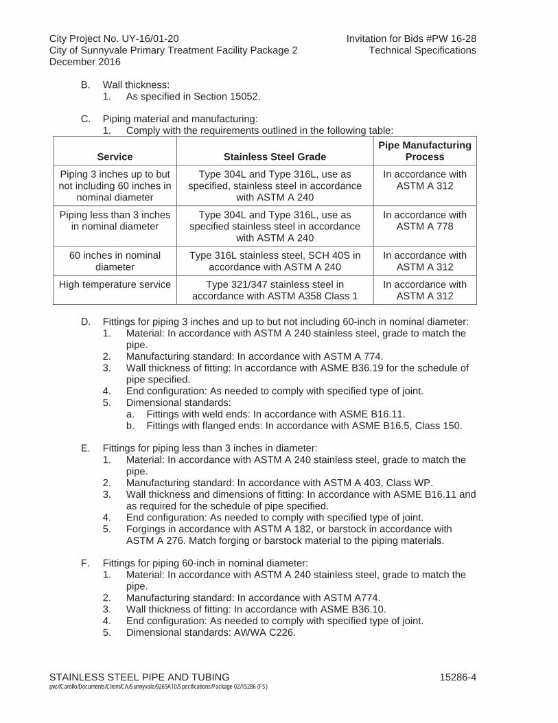
City Project No. UY-16/01-20 Invitation for Bids #PW 16-28City of Sunnyvale Primary Treatment Facility Package 2 Technical SpecificationsDecember 2016
STAINLESS STEEL PIPE AND TUBING 15286-4 pw://Carollo/Documents/Client/CA/Sunnyvale/9265A10/Specifications/Package 02/15286 (FS)
B. Wall thickness:1. As specified in Section 15052.
C. Piping material and manufacturing:1. Comply with the requirements outlined in the following table:
Service Stainless Steel GradePipe Manufacturing
ProcessPiping 3 inches up to but not including 60 inches in
nominal diameter
Type 304L and Type 316L, use as specified, stainless steel in accordance
with ASTM A 240
In accordance withASTM A 312
Piping less than 3 inches in nominal diameter
Type 304L and Type 316L, use as specified stainless steel in accordance
with ASTM A 240
In accordance with ASTM A 778
60 inches in nominal diameter
Type 316L stainless steel, SCH 40S in accordance with ASTM A 240
In accordance withASTM A 312
High temperature service Type 321/347 stainless steel in accordance with ASTM A358 Class 1
In accordance withASTM A 312
D. Fittings for piping 3 inches and up to but not including 60-inch in nominal diameter:1. Material: In accordance with ASTM A 240 stainless steel, grade to match the
pipe.2. Manufacturing standard: In accordance with ASTM A 774.3. Wall thickness of fitting: In accordance with ASME B36.19 for the schedule of
pipe specified.4. End configuration: As needed to comply with specified type of joint.5. Dimensional standards:
a. Fittings with weld ends: In accordance with ASME B16.11.b. Fittings with flanged ends: In accordance with ASME B16.5, Class 150.
E. Fittings for piping less than 3 inches in diameter:1. Material: In accordance with ASTM A 240 stainless steel, grade to match the
pipe.2. Manufacturing standard: In accordance with ASTM A 403, Class WP.3. Wall thickness and dimensions of fitting: In accordance with ASME B16.11 and
as required for the schedule of pipe specified.4. End configuration: As needed to comply with specified type of joint.5. Forgings in accordance with ASTM A 182, or barstock in accordance with
ASTM A 276. Match forging or barstock material to the piping materials.
F. Fittings for piping 60-inch in nominal diameter: 1. Material: In accordance with ASTM A 240 stainless steel, grade to match the
pipe.2. Manufacturing standard: In accordance with ASTM A774.3. Wall thickness of fitting: In accordance with ASME B36.10. 4. End configuration: As needed to comply with specified type of joint.5. Dimensional standards: AWWA C226.
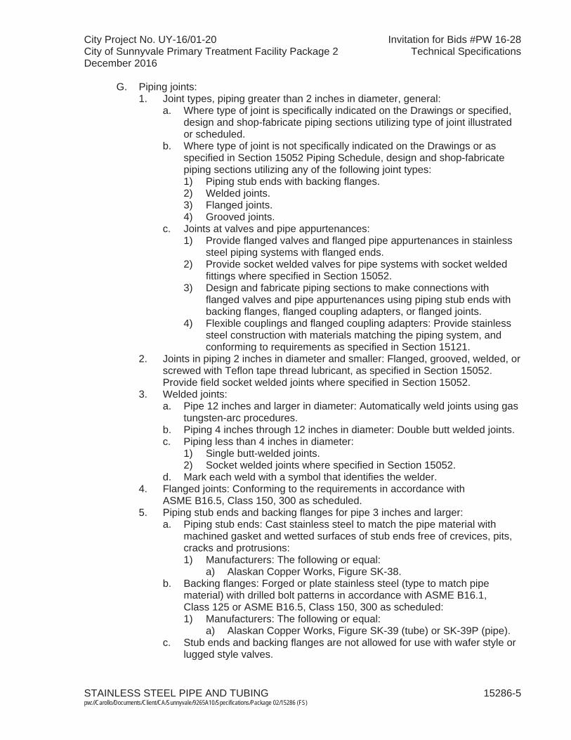
City Project No. UY-16/01-20 Invitation for Bids #PW 16-28City of Sunnyvale Primary Treatment Facility Package 2 Technical SpecificationsDecember 2016
STAINLESS STEEL PIPE AND TUBING 15286-5 pw://Carollo/Documents/Client/CA/Sunnyvale/9265A10/Specifications/Package 02/15286 (FS)
G. Piping joints:1. Joint types, piping greater than 2 inches in diameter, general:
a. Where type of joint is specifically indicated on the Drawings or specified, design and shop-fabricate piping sections utilizing type of joint illustrated or scheduled.
b. Where type of joint is not specifically indicated on the Drawings or as specified in Section 15052 Piping Schedule, design and shop-fabricate piping sections utilizing any of the following joint types:1) Piping stub ends with backing flanges.2) Welded joints.3) Flanged joints.4) Grooved joints.
c. Joints at valves and pipe appurtenances:1) Provide flanged valves and flanged pipe appurtenances in stainless
steel piping systems with flanged ends.2) Provide socket welded valves for pipe systems with socket welded
fittings where specified in Section 15052.3) Design and fabricate piping sections to make connections with
flanged valves and pipe appurtenances using piping stub ends with backing flanges, flanged coupling adapters, or flanged joints.
4) Flexible couplings and flanged coupling adapters: Provide stainlesssteel construction with materials matching the piping system, and conforming to requirements as specified in Section 15121.
2. Joints in piping 2 inches in diameter and smaller: Flanged, grooved, welded, or screwed with Teflon tape thread lubricant, as specified in Section 15052. Provide field socket welded joints where specified in Section 15052.
3. Welded joints:a. Pipe 12 inches and larger in diameter: Automatically weld joints using gas
tungsten-arc procedures.b. Piping 4 inches through 12 inches in diameter: Double butt welded joints. c. Piping less than 4 inches in diameter:
1) Single butt-welded joints. 2) Socket welded joints where specified in Section 15052.
d. Mark each weld with a symbol that identifies the welder.4. Flanged joints: Conforming to the requirements in accordance with
ASME B16.5, Class 150, 300 as scheduled. 5. Piping stub ends and backing flanges for pipe 3 inches and larger:
a. Piping stub ends: Cast stainless steel to match the pipe material with machined gasket and wetted surfaces of stub ends free of crevices, pits, cracks and protrusions:1) Manufacturers: The following or equal:
a) Alaskan Copper Works, Figure SK-38.b. Backing flanges: Forged or plate stainless steel (type to match pipe
material) with drilled bolt patterns in accordance with ASME B16.1, Class 125 or ASME B16.5, Class 150, 300 as scheduled: 1) Manufacturers: The following or equal:
a) Alaskan Copper Works, Figure SK-39 (tube) or SK-39P (pipe).c. Stub ends and backing flanges are not allowed for use with wafer style or
lugged style valves.

City Project No. UY-16/01-20 Invitation for Bids #PW 16-28City of Sunnyvale Primary Treatment Facility Package 2 Technical SpecificationsDecember 2016
STAINLESS STEEL PIPE AND TUBING 15286-6 pw://Carollo/Documents/Client/CA/Sunnyvale/9265A10/Specifications/Package 02/15286 (FS)
6. Flanges for Schedule 40S and Schedule 80S pipe:a. Provide forged stainless steel (type matching piping system) welding neck
flanges or slip-on flanges in accordance with ASME B16.5 Class 150. b. Material: In accordance with ASTM A 182.
7. Grooved joints:a. Pressure less than 500 pounds per square inch:
1) Cut grooves from Schedule 40 or higher.b. Heavier schedule pipe sections used for cut groove ends:
1) Tapered inside diameter to transition from the inside diameter of the lighter schedule pipe.
c. Butt welds connecting pipes of different schedules that leave an abrupt change in inside diameter are not allowed.
d. Couplings:1) Type 316 (Grade CF-8M) stainless steel in accordance with
ASTM A 351, A 743, and A 744:a) Bolts: Stainless steel in accordance with ASTM F 593, Group 2,
Condition CW.b) Nuts: Stainless steel.c) Manufacturers: The following or equal:
(1) Piedmont Pacific Corporation.(2) Victaulic Style 489 Rigid Coupling.
H. Gaskets:1. Aeration air service: As specified in Section 15052. 2. All other service applications: EPDM, nitrile, or other materials compatible with
the process fluid.
I. Expansion Joints:1. Aeration air service: Bellows type expansion joint as specified in Section
15120.
J. Bolts for flanges and stub end/backing flanges: 1. Bolts and nuts: Type 316 stainless steel in accordance with ASTM A 193
heavy hex head:a. Bolt length such that after installation, end of bolt projects 1/8-inch to
3/8-inch beyond outer face of nut.b. Nuts: In accordance with ASTM A 194 heavy hex pattern.
K. Fabrication of pipe sections:1. Welding: Weld in accordance with ASME B31.3. 2. Weld seams:
a. Full penetration welds, free of oxidation, crevices, pits and cracks, and without undercuts.
b. Provide weld crowns of 1/16 inch with tolerance of plus 1/16 inch and minus 1/32 inch.
c. Where internal weld seams are not accessible, use gas tungsten-arc procedures with internal gas purge.
d. Where internal weld seams are accessible, weld seams inside and outside using manual shielded metal-arc procedures.
e. Field welded joints shall be passivated inside and out.

City Project No. UY-16/01-20 Invitation for Bids #PW 16-28City of Sunnyvale Primary Treatment Facility Package 2 Technical SpecificationsDecember 2016
STAINLESS STEEL PIPE AND TUBING 15286-7 pw://Carollo/Documents/Client/CA/Sunnyvale/9265A10/Specifications/Package 02/15286 (FS)
L. Cleaning (pickling) and passivation:1. Following shop fabrication of pipe sections, straight spools, fittings, and other
piping components, clean (pickle) and passivate fabricated pieces.2. Clean (pickle) and passivate in accordance with ASTM A 380 or A 967:
a. If degreasing is required before cleaning to remove scale or iron oxide, cleaning (pickling) treatments with citric acid are permissible:1) However, these treatments must be followed by inorganic cleaners
such as nitric acid/hydrofluoric acid.b. Passivation treatments with citric acid are not allowed.
3. Finish requirements: Remove free iron, heat tint oxides, weld scale, and other impurities, and obtain a passive finished surface.
2.02 STAINLESS STEEL TUBING
A. Stainless steel tubing:1. Seamless tubing made of Type 316L stainless steel and in accordance with
ASTM A 269, wall thickness not less than 0.035 inch.
B. Fittings: Swage ferrule design:1. Components made of:
a. Type 316 stainless steel.2. Double acting ferrule design, providing both a primary seal and a secondary
bearing force.3. Flare type fittings are not acceptable.4. Manufacturers: One of the following or equal:
a. Crawford Fitting Company, Swagelok.b. Hoke, Gyrolok.c. Parker, CPI.
C. Valves for use with stainless steel tubing:1. Ball type valves with swage ends to match tubing diameter.2. Constructed from:
a. Type 316 stainless steel with TFE seats.3. Manufacturers: The following or equal:
a. Crawford Fitting Company, Swagelok.
2.03 SOURCE QUALITY CONTROL
A. Visually inspect pipe for welding defects such as crevices, pits, cracks, protrusions, and oxidation deposits.
B. Provide written certification that the pipe as supplied are in accordance with ASTM A 778. Supplemental testing is not required.
C. Provide written certification that the fittings as supplied are in accordance with ASTM A 774:1. Supplementary testing is not required.

City Project No. UY-16/01-20 Invitation for Bids #PW 16-28City of Sunnyvale Primary Treatment Facility Package 2 Technical SpecificationsDecember 2016
STAINLESS STEEL PIPE AND TUBING 15286-8 pw://Carollo/Documents/Client/CA/Sunnyvale/9265A10/Specifications/Package 02/15286 (FS)
D. Examine 3 percent or up to 20 of the factory welds and all field welds by radiography. For each weld that fails, inspect 3 additional welds using the same methods:1. Radiographic methods: In accordance with standards of AWS Standard D1.6
(Chapter 6).2. For each weld found to be defective by radiographic methods, examine
3 additional welds using the same method.3. Provide interpretation of radiographic pictures by an independent testing
laboratory acceptable to Engineer, and submit written report of the findings issued by the laboratory.
4. Repair or replace defective joints.
E. Thoroughly clean any equipment before use in cleaning or fabrication of stainless steel.
F. Storage: Segregate location of stainless steel piping from fabrication of any other piping materials.
G. Shipment to site: 1. Protect all flanges and pipe ends by encapsulating in dense foam.2. Securely strap all elements to pallets with nylon straps. Use of metallic straps
is prohibited.3. Cap ends of tube, piping, pipe spools, fittings, and valves with non-metallic
plugs. 4. Load pallets so no tube, piping, pipe spools, fittings, or valves bear the weight
of pallets above.5. Notify Engineer when deliveries arrive so Engineer may inspect the shipping
conditions.6. Engineer may reject material due to improper shipping methods or damage
during shipment.
PART 3 EXECUTION
3.01 INSTALLATION
A. Install piping in such a manner as not to impart strain to connected equipment.
B. Slope horizontal lines so that they can be drained completely.
C. Provide valve drains at low points in piping systems.
D. Install eccentric reducers where necessary to facilitate draining of piping system.
E. Provide access for inspection and flushing of piping systems to remove sediment, deposits, and debris.
3.02 FIELD ASSEMBLY OF SHOP-FABRICATED PIPING SECTIONS
A. Join shop-fabricated piping sections together using backing flanges, flexible couplings, flanged coupling adapters, grooved couplings, or flanges.
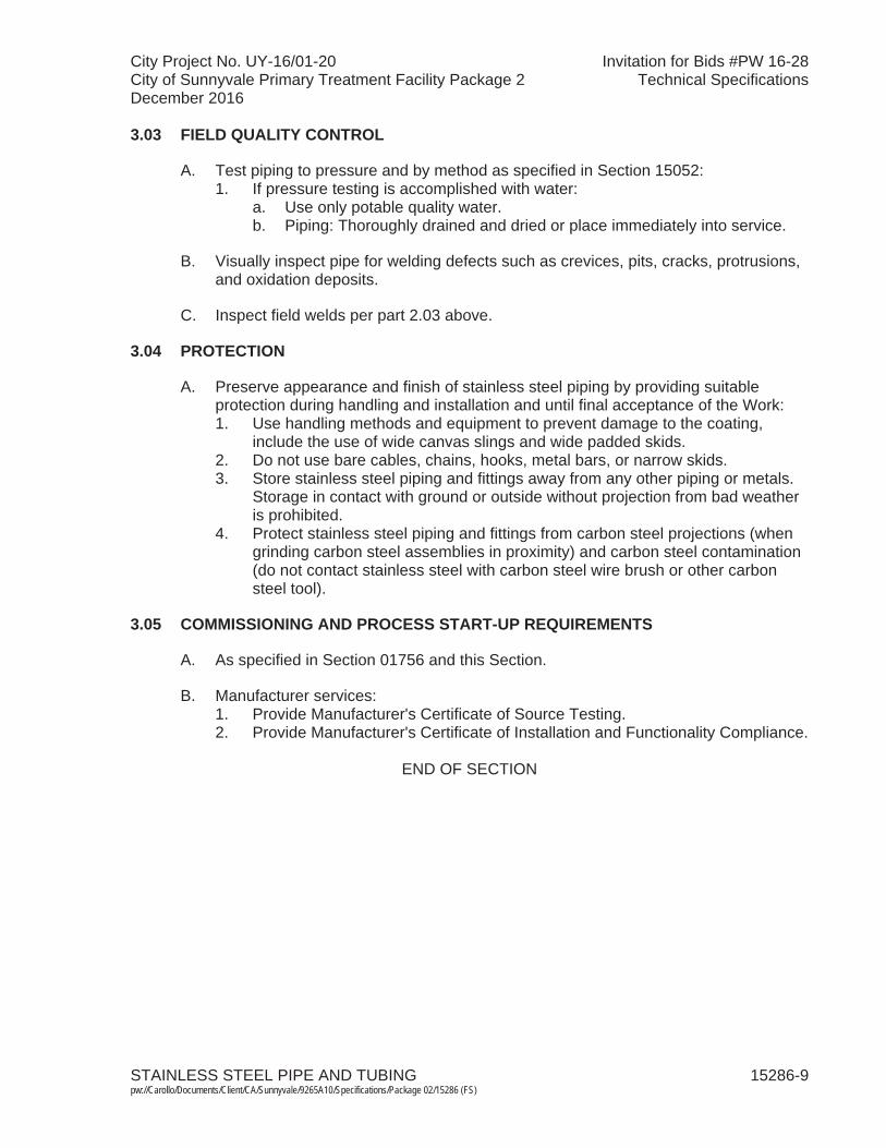
City Project No. UY-16/01-20 Invitation for Bids #PW 16-28City of Sunnyvale Primary Treatment Facility Package 2 Technical SpecificationsDecember 2016
STAINLESS STEEL PIPE AND TUBING 15286-9 pw://Carollo/Documents/Client/CA/Sunnyvale/9265A10/Specifications/Package 02/15286 (FS)
3.03 FIELD QUALITY CONTROL
A. Test piping to pressure and by method as specified in Section 15052: 1. If pressure testing is accomplished with water:
a. Use only potable quality water.b. Piping: Thoroughly drained and dried or place immediately into service.
B. Visually inspect pipe for welding defects such as crevices, pits, cracks, protrusions, and oxidation deposits.
C. Inspect field welds per part 2.03 above.
3.04 PROTECTION
A. Preserve appearance and finish of stainless steel piping by providing suitable protection during handling and installation and until final acceptance of the Work:1. Use handling methods and equipment to prevent damage to the coating,
include the use of wide canvas slings and wide padded skids.2. Do not use bare cables, chains, hooks, metal bars, or narrow skids.3. Store stainless steel piping and fittings away from any other piping or metals.
Storage in contact with ground or outside without projection from bad weather is prohibited.
4. Protect stainless steel piping and fittings from carbon steel projections (when grinding carbon steel assemblies in proximity) and carbon steel contamination (do not contact stainless steel with carbon steel wire brush or other carbon steel tool).
3.05 COMMISSIONING AND PROCESS START-UP REQUIREMENTS
A. As specified in Section 01756 and this Section.
B. Manufacturer services: 1. Provide Manufacturer's Certificate of Source Testing.2. Provide Manufacturer's Certificate of Installation and Functionality Compliance.
END OF SECTION

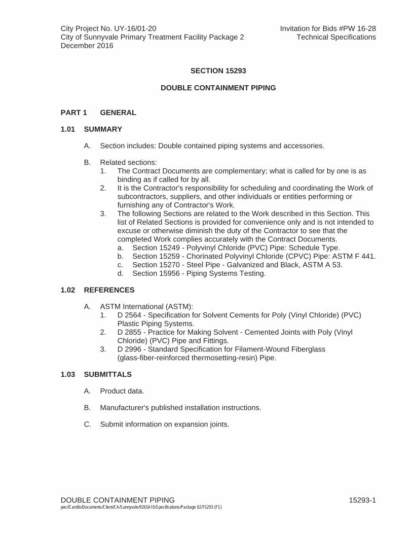
City Project No. UY-16/01-20 Invitation for Bids #PW 16-28City of Sunnyvale Primary Treatment Facility Package 2 Technical SpecificationsDecember 2016
DOUBLE CONTAINMENT PIPING 15293-1 pw://Carollo/Documents/Client/CA/Sunnyvale/9265A10/Specifications/Package 02/15293 (FS)
SECTION 15293
DOUBLE CONTAINMENT PIPING
PART 1 GENERAL
1.01 SUMMARY
A. Section includes: Double contained piping systems and accessories.
B. Related sections: 1. The Contract Documents are complementary; what is called for by one is as
binding as if called for by all.2. It is the Contractor's responsibility for scheduling and coordinating the Work of
subcontractors, suppliers, and other individuals or entities performing or furnishing any of Contractor's Work.
3. The following Sections are related to the Work described in this Section. This list of Related Sections is provided for convenience only and is not intended to excuse or otherwise diminish the duty of the Contractor to see that the completed Work complies accurately with the Contract Documents.a. Section 15249 - Polyvinyl Chloride (PVC) Pipe: Schedule Type. b. Section 15259 - Chorinated Polyvinyl Chloride (CPVC) Pipe: ASTM F 441.c. Section 15270 - Steel Pipe - Galvanized and Black, ASTM A 53. d. Section 15956 - Piping Systems Testing.
1.02 REFERENCES
A. ASTM International (ASTM):1. D 2564 - Specification for Solvent Cements for Poly (Vinyl Chloride) (PVC)
Plastic Piping Systems.2. D 2855 - Practice for Making Solvent - Cemented Joints with Poly (Vinyl
Chloride) (PVC) Pipe and Fittings.3. D 2996 - Standard Specification for Filament-Wound Fiberglass
(glass-fiber-reinforced thermosetting-resin) Pipe.
1.03 SUBMITTALS
A. Product data.
B. Manufacturer's published installation instructions.
C. Submit information on expansion joints.

City Project No. UY-16/01-20 Invitation for Bids #PW 16-28City of Sunnyvale Primary Treatment Facility Package 2 Technical SpecificationsDecember 2016
DOUBLE CONTAINMENT PIPING 15293-2 pw://Carollo/Documents/Client/CA/Sunnyvale/9265A10/Specifications/Package 02/15293 (FS)
PART 2 PRODUCTS
2.01 DOUBLE CONTAINMENT PLASTIC PIPING SYSTEM
A. Materials:1. Compatible for continuous exposure to chemical service as indicated in the
pipe schedule at ambient temperatures and maximum pressure equal to the test pressure.
2. Prefabricated fittings:a. Prefabricated fittings consisting of an inner (carrier) pipe elbow totally
enclosed and spaced in an outer (containment) pipe elbow.b. Split fittings requiring field cutting, welding or joining shall not be used.
3. Inner (carrier) pipe: Shall consist of Schedule 80 CPVC/PVC pipe, joined to fittings and each other solvent welding. Provide pipe as specified in Sections 15249 and 15259.
4. Outer (containment) pipe: Shall consist of Schedule 40 PVC pipe. Provide pipe as specified in Section 15249.
5. Spacers:a. Provide nonmetallic spacers on inner pipe to control sagging within
containment pipe.b. Design and place spacers to withstand loads of the filled pipe and loads
due to thermal expansion. Spacers shall be free of sharp edges and be bonded to the carrier pipe.
B. Design requirements:1. Expansion loops: Provide expansion loops as required to compensate for
expected thermal expansion for an ambient temperature range of 45 to 90 degrees Fahrenheit.
2. Access ports:a. Provide access ports for ease of installation, start-up, and maintenance of
piping. Access ports shall consist of a tee fitting in the secondary containment piping, a 6-inch diameter riser pipe, and a bolted blind flange cover.
b. Locate access ports at each low point.3. Leak detection: Provide leak detection tee at each low point as indicated on
the Drawings.
C. Manufacturers: One of the following or equal:1. Guardian Systems, a product of IPEX Inc.2. Harrington Industrial Plastics.3. Permalert.
2.02 DOUBLE CONTAINMENT STEEL PIPING SYSTEM
A. Materials:1. Material compatible with fuel oil. 2. Inner carrier pipe: Schedule 40 black steel pipe. Provide pipe as specified in
Section 15270. 3. Outer (containment) pipe and fittings: Fiberglass epoxy or vinyl ester. Pipe
shall meet ASTM specification D 2996 and be UL listed.

City Project No. UY-16/01-20 Invitation for Bids #PW 16-28City of Sunnyvale Primary Treatment Facility Package 2 Technical SpecificationsDecember 2016
DOUBLE CONTAINMENT PIPING 15293-3 pw://Carollo/Documents/Client/CA/Sunnyvale/9265A10/Specifications/Package 02/15293 (FS)
4. Containment systems shall be jointed in the field using 2- or 4-piece clamshell type fittings or the Quick-Lock joint for adjacent pipe lengths.
5. Spacers: Provide nonmetallic spacers on inner pipe to control sagging within containment pipe.
6. Provide low point sump in piping with provision for installation of a leak detector.7. Provide special leak proof fittings to enclose all inner pipe fittings and yet allow
any leaks to flow to the low point.
B. Manufacturers: One of the following or equal:1. Ameron, Dualoy.2. Fibercast, Dualcast.
PART 3 EXECUTION
3.01 INSTALLATION
A. Plastic piping systems: 1. Secondary containment joints solvent cemented using heavy body-slow set
PVC cement ASTM D 2564 made in accordance with ASTM D 2855.2. Install piping in accordance with manufacturers published instructions.3. Pipe shall be continuously sloped to drain to a low point. Provide tee with
minimum 3-inch riser pipe to grade for inspection and access at all low points for buried double containment pipe. Provide threaded cap at top of riser pipe installed in a valve box.
4. Provide tee with minimum 2-inch drainpipe with ball valve at all piping low points for exposed double containment piping.
5. Ends of outer containment pipe shall be closed.
B. Steel piping systems:1. Install piping in accordance with manufacturer's published instructions.
3.02 FIELD QUALITY CONTROL
A. Plastic piping systems:1. Test Schedule 80 PVC (inner containment) pipe per testing methods specified
in Section 15956. 2. Test Schedule 40 PVC (outer containment) pipe as follows:
a. Pneumatically test the pipe at a minimum of 5 pounds per square inch and a maximum of 10 pounds per square inch air pressure for 2-1/2 hours.
b. Soap all external joints and visually inspect for leaks. All leaks shall be repaired in accordance with manufacturer's recommendations.
c. Purge containment pipe annular space with nitrogen to remove moisture containing air following leak test.
B. Steel piping:1. Test Schedule 40 black steel (inner containment) pipe as specified in
Section 15956.
City Project No. UY-16/01-20 Invitation for Bids #PW 16-28City of Sunnyvale Primary Treatment Facility Package 2 Technical SpecificationsDecember 2016
DOUBLE CONTAINMENT PIPING 15293-4 pw://Carollo/Documents/Client/CA/Sunnyvale/9265A10/Specifications/Package 02/15293 (FS)
2. Test fiberglass epoxy or vinyl ester (outer containment) pipe as follows:a. Pneumatically test the pipe at a minimum of 5 pounds per square inch and
a maximum of 10 pounds per square inch air pressure for 2-1/2 hours.b. Soap all external joints and visually inspect for leaks. All leaks shall be
repaired in accordance with manufacturer's recommendations.c. Purge containment pipe annular space with nitrogen to remove moisture
containing air following leak test.
END OF SECTION
City Project No. UY-16/01-20 Invitation for Bids #PW 16-28City of Sunnyvale Primary Treatment Facility Package 2 Technical SpecificationsDecember 2016
PLUMBING FIXTURES AND EQUIPMENT 15400-1 pw://Carollo/Documents/Client/CA/Sunnyvale/9265A10/Specifications/Package 02/15400 (FS)
SECTION 15400
PLUMBING FIXTURES AND EQUIPMENT
PART 1 GENERAL
1.01 SUMMARY
A. Section includes: Materials and installation of plumbing system.
B. Related sections:1. The Contract Documents are complementary; what is called for by one is as
binding as if called for by all.2. It is the Contractor's responsibility for scheduling and coordinating the Work of
subcontractors, suppliers, and other individuals or entities performing or furnishing any of Contractor's Work.
3. The following Sections are related to the Work described in this Section. This list of Related Sections is provided for convenience only and is not intended to excuse or otherwise diminish the duty of the Contractor to see that the completed Work complies accurately with the Contract Documents: a. Section 01340 - Shop Drawings, Product Data and Samples. b. Section 01060 - Regulatory Permits and Requirements.c. Section 01612 - Seismic Design Criteria.d. Section 01614 - Wind Design Criteria.e. Section 01756 - Commissioning and Process Start-Up.f. Section 07620 - Sheet Metal Flashing and Trim. g. Section 15050 - General Work Results for Mechanical Equipment.h. Section 15052 - Common Work Results for General Piping. i. Section 15956 - Piping Systems Testing.
1.02 REFERENCES
A. American Society of Mechanical Engineers (ASME).
B. ASTM International (ASTM).
C. National Electrical Manufacturers Association (NEMA):1. 250- Enclosures for Electrical Equipment (1000 V Maximum).
D. Plumbing and Drainage Institute (PDI):1. PDI-WH 201 - Water Hammer Arresters Standard.
E. Title 24 of the California Code of Regulations.
F. US EPA:1. WaterSense Tank-Type High-Efficiency Toilet Specification.
1.03 DEFINITIONS
A. NEMA Type 3 enclosure in accordance with NEMA 250.
City Project No. UY-16/01-20 Invitation for Bids #PW 16-28City of Sunnyvale Primary Treatment Facility Package 2 Technical SpecificationsDecember 2016
PLUMBING FIXTURES AND EQUIPMENT 15400-2 pw://Carollo/Documents/Client/CA/Sunnyvale/9265A10/Specifications/Package 02/15400 (FS)
1.04 SYSTEM DESCRIPTION
A. System requirements:1. Include in plumbing system fixtures; soil, drain, vent, and water piping;
connections; cleanouts, fittings, accessories, and testing for complete and functional system.
2. Except in details, piping is indicated on the Drawings in diagrammatic form. Sizes and locations are indicated on the Drawings; however, not every offset and fitting, nor every structural difficulty that will be encountered in the Work has been indicated.
3. As part of the Work, modify piping alignment indicated on the Drawings as necessary to avoid structural or mechanical obstructions and to clear the work of other trades.
4. Furnish such parts and pieces necessary to provide a complete and operational system.
1.05 SUBMITTALS
A. Submit as specified in Section 01340.
B. Product data for each type of fixture or equipment:1. Shop drawings: Details, dimensions, and materials.
C. Installation instructions.
D. Provide Manufacturer's Certificate of Source Testing as specified in Section 01756.
E. Provide Manufacturer's Certificate of Installation and Functionality Compliance as specified in Section 01756.
F. Manufacturer's recommendations for sizing and locating each unit.
G. Manufacturer's warranties for all water heaters, water softeners, and duplex automatic water filters.
1.06 QUALITY ASSURANCE
A. Regulatory requirements: Perform work under this Section in accordance with the plumbing code specified in Section 01060, and in accordance with applicable laws and regulations, including requirements for accessibility, energy, water conservation, and health including related requirements for water fountains and coolers:1. Where provisions specified in these Specifications or the design indicated on
the Drawings are in conflict with the plumbing code specified in Section 01060or laws or regulations, the Code and the laws or regulations take precedence over the specified provisions and design.
B. All devices and fixtures supplied for projects in the State of California shall comply with Title 24 of the California Code of Regulations.
City Project No. UY-16/01-20 Invitation for Bids #PW 16-28City of Sunnyvale Primary Treatment Facility Package 2 Technical SpecificationsDecember 2016
PLUMBING FIXTURES AND EQUIPMENT 15400-3 pw://Carollo/Documents/Client/CA/Sunnyvale/9265A10/Specifications/Package 02/15400 (FS)
PART 2 PRODUCTS
2.01 MATERIALS
A. General:1. Manufactured units: Fixture fittings and piping which are exposed shall be
heavy-duty chrome.2. Accessories:
a. Stops:1) Fixtures, except showers, shall have stops at the fixtures' service.2) Stops for laboratory equipment, and for other equipment or fixtures
for which stops have not been otherwise specified in this Section, shall be chrome-plated straight pattern compression stops or chrome-plated angle pattern compression stops.
B. Drain, waste, and vent piping:1. Piping:
a. Piping for drain, waste, and vent: As specified in Section 15052. 2. Joints:
a. Threaded joints: American standard taper screw threads, clean cut, and made up with graphite and oil or other suitable pipe compounds.
b. Slip joints permitted only in trap seals or on the inlet side of the traps:1) Do not use long screws or bushings.
c. Other types of joints: As specified in the piping sections. 3. Fittings:
a. Fittings for screwed waste and vent piping: Cast iron drainage pattern fittings.
b. Additional provisions for fittings specified within piping section.4. Flashing:
a. Roof vent, roof drain, and pipe flashing: Minimum 4-pound lead sheet.
C. Plumbing piping accessories:1. Cleanouts:
a. Wall-mounted cleanouts (WCO) for concealed piping: Provide complete including cast-iron tapped tee, round smooth stainless steel access cover, and securing screw:1) Manufacturers: One of the following or equal:
a) Josam Company, 58910-19 (Tee & Plug) and 58600 (Access Cover).
b) Zurn Industries, Z1446-BP. b. Floor cleanouts (FCO) in finished floor areas: Provide complete including
cast-iron ferrule, countersunk plug, gastight and watertight seal, adjustable cleanout head extension, scoriated nickel-bronze top, and securing screw:1) Manufacturers: One of the following or equal:
a) Josam Company, 56070.b) Zurn Industries, Inc., ZN-1400.

City Project No. UY-16/01-20 Invitation for Bids #PW 16-28City of Sunnyvale Primary Treatment Facility Package 2 Technical SpecificationsDecember 2016
PLUMBING FIXTURES AND EQUIPMENT 15400-4 pw://Carollo/Documents/Client/CA/Sunnyvale/9265A10/Specifications/Package 02/15400 (FS)
c. Floor cleanouts (FCO) in unfinished floor areas: Same as floor cleanouts specified for finished floor areas, except heavy-duty scoriated nickel-bronze top suitable for heavy traffic conditions:1) Manufacturers: One of the following or equal:
a) Josam Company, 55000. b) Zurn Industries, Inc., ZN-1400-HD.
d. Yard cleanouts (YCO) in asphalt or ground areas: As shown on the Drawings.
2. Floor drainage:a. Floor drainage piping: Refer to the Piping Schedule in Section 15052.b. Equipment and floor drains:
1) Provide with adjustable strainer head, floor level grate, 4-inch diameter funnel extension and provided with no-hub outlet and nickel bronze top.
2) Manufacturers: One of the following or equal:a) Floor drain:
(1) Josam Company, 30000-A, combination drip drain, less clamping collar.
(2) Zurn Industries, Inc., ZN-415 strainer.b) Funnel extension:
(1) Josam Company, E-2.(2) Zurn Industries, Inc., ZN-328.
c) Other floor drains with no-hub outlet and nickel bronze Type B strainer:(1) Josam Company, 30000-A universal floor drain with
adjustable strainer, less clamping collar.(2) Zurn Industries, Inc., ZN-415.
3) Strainer sizing:a) 3-inch drain strainers: 6-inch diameter. b) 4-inch drain strainers: 8-inch diameter.
c. Heavy-duty floor drains with sedimentation bucket:1) 12 inches square with coated cast-iron body, grate, and slotted
sediment bucket. 2) Manufacturers: One of the following or equal:
a) Josam Company, 37810. b) Zurn Industries, Inc., Z-610.
d. Heavy-duty floor drains with internal trap: 1) 12 inches square, coated cast-iron body with side outlet.2) Hinged heavy-duty slotted grate with suspended aluminum sediment
bucket.3) Manufacturers: One of the following or equal:
a) Josam Company, 38830.b) Zurn Industries, Inc., Z-645.
e. Floor sinks: 1) Floor sinks for grit or solids handling areas:
a) Full, half, or quarter grate, 12 inches square by 7 inches deep, acid-resisting enamel interior and exterior, no-hub outlet, pipe size as indicated on the Drawings.
City Project No. UY-16/01-20 Invitation for Bids #PW 16-28City of Sunnyvale Primary Treatment Facility Package 2 Technical SpecificationsDecember 2016
PLUMBING FIXTURES AND EQUIPMENT 15400-5 pw://Carollo/Documents/Client/CA/Sunnyvale/9265A10/Specifications/Package 02/15400 (FS)
b) Manufacturers: One of the following or equal:(1) Josam Company, 49420.(2) Zurn Industries, Inc., Z-1920.
3. Roof drains:a. Per Section 07620.
D. Water heaters:1. Electric water heaters:
a. Equipment Tag: HEA-212.001:1) Provide complete with 80 gallon glass lined storage tank, 2 inches
minimum fiberglass insulation, exterior steel casing with factory standard enamel finish, 90,000-watt high efficiency immersion type heating elements, automatic temperature control and externally adjustable setting, recovery rate of 360 gallons per hour at100 degrees Fahrenheit temperature rise; ASME rated temperature and pressure relief valve, magnesium anode, tank cleanout, 3-year warranty, Underwriter's Laboratory listed; suitable for 480-V,3-phase, 60-hertz electrical power supply as indicated on Drawings.
2) Water heater shall meet the requirements of Title 24 of the California Code of Regulations.
3) Provide seismic straps as required.4) Route discharge from the integral temperature & pressure relief valve
to nearest floor drain.5) Manufacturers: One of the following or equal:
a) State Industries, Inc.b) A. O. Smith Corporation.
E. Surge expansion tank: 1. Tag number: TNK-212.001. 2. Tank size: 53 gallons. 3. Maximum operating pressure: 110 psi.
a. Surge tanks shall be fabricated in accordance with the ASME Code for unfired pressure vessels, for a design pressure rating of 50 pounds per square inch gauge above the maximum operating pressure.
b. Corrosion allowance: 1/16 of an inch. 4. Service: UW - chlorinated filtered plant effluent.5. Anchorage calculations: Submit per Section 15050.
a. Seismic design: Per Section 01612. 1) Provide integral support framing with welded angles for bolting the
tank onto concrete floor.b. Wind design: Per Section 01614.
6. Construction:a. ASME steel tank. b. Heavy-duty butyl bladder.c. Shop prime to match field coating as specified in Section 09960.d. Air valve: Schrader valve with EPDM seal.
7. Manufacturers: One of the following or equal.a. Amtrol. b. AATanks. c. Wessels Company.

City Project No. UY-16/01-20 Invitation for Bids #PW 16-28City of Sunnyvale Primary Treatment Facility Package 2 Technical SpecificationsDecember 2016
PLUMBING FIXTURES AND EQUIPMENT 15400-6 pw://Carollo/Documents/Client/CA/Sunnyvale/9265A10/Specifications/Package 02/15400 (FS)
PART 3 EXECUTION
3.01 PREPARATION
A. Rough-in fixtures and accessories in accordance with the dimensions supplied by the manufacturers of the fixtures.
3.02 INSTALLATION
A. General:1. Mount fixtures and accessories without cutting of finish surface.2. Make cross connections between piping for domestic water supply and piping
for contaminated sources only by means of appropriate connection devices that prevent backflow from the contaminated sources to the domestic water supply:a. Provide connection devices approved by the Public Health authorities
having jurisdiction over the Work.3. Conceal plumbing piping unless otherwise indicated on the Drawings or
specified in the specifications.4. Furnish and install vents required in drainage piping as part of the plumbing
system, in accordance with Laws and Regulations.5. Insulate hot water piping per Section 15082.
B. Drain, waste, and vent piping:1. Where not specified otherwise, install horizontal piping with a grade of 1/4 inch
per foot.2. Provide vents, roof drains, and pipes flashed and made watertight at the roof
with lead sheet flashings.3. Extend flashing not less than 6 inches up the pipes, and counterflash with
standard cast iron or malleable iron recessed roof couplings.4. Extend flashing for vents up to the top of the vent and turn down into the pipe.5. Extend flashing shields not less than 8 inches from vent and pipe in all
directions.
C. Plumbing piping accessories:1. Provide cleanouts of the same size as the size of the waste and drain piping
on which cleanouts are installed, up to 4 inches in diameter. Provide cleanouts 4 inches in diameter on waste and drain piping larger than 4 inches diameter.
2. Sizes of equipment drains and of floor drains shall be as indicated on the Drawings.
3. When indicated on the Drawings, cut holes in heavy-duty floor drain grate for a drainpipe from equipment or other source.
3.03 FIELD QUALITY CONTROL
A. Testing:1. Test soil, waste, drain, and vent lines as specified and in accordance with
plumbing code as specified in Sections 01060 and 15052.2. Repair and correct defective work disclosed by testing. Repeat testing until
defective work is corrected.
City Project No. UY-16/01-20 Invitation for Bids #PW 16-28City of Sunnyvale Primary Treatment Facility Package 2 Technical SpecificationsDecember 2016
PLUMBING FIXTURES AND EQUIPMENT 15400-7 pw://Carollo/Documents/Client/CA/Sunnyvale/9265A10/Specifications/Package 02/15400 (FS)
3.04 COMMISSIONING AND PROCESS START-UP REQUIREMENTS
A. As specified in Section 01756 and this Section.
B. Manufacturer (each) services for each type of fixture or equipment:1. Provide Manufacturer's Certificate of Source Testing.
C. Manufacturer (each) services for the fixture or equipment in the following:1. Electric water heater.
a. Provide Manufacturer's Certificate of Installation and Functionality Compliance.
b. Manufacturer's Representative onsite requirements:1) Installation: 1 trip, 2 days minimum each.2) Functional Testing: 1 trip, 1 day minimum each.
c. Training:1) Maintenance: 2 hours per session, 2 sessions. 2) Operation: 2 hours per session, 2 sessions.
2. Process operational period:a. As required by Owner or Contractor.
D. Functional Testing:1. Pressure testing as specified in Sections 15052 and 15956.
3.05 CLEANING
A. Flush piping and leave clean, as required by public health authorities having jurisdiction over the Work.
END OF SECTION

City Project No. UY-16/01-20 Invitation for Bids #PW 16-28City of Sunnyvale Primary Treatment Facility Package 2 Technical SpecificationsDecember 2016
EMERGENCY EYE/FACE WASH AND SHOWER EQUIPMENT 15430-1 pw://Carollo/Documents/Client/CA/Sunnyvale/9265A10/Specifications/Package 02/15430 (FS)
SECTION 15430
EMERGENCY EYE/FACE WASH AND SHOWER EQUIPMENT
PART 1 GENERAL
1.01 SUMMARY
A. Section includes: Emergency shower and eyewash.
B. Equipment Tag Numbers:1. Polymer Pump Area Emergency Eyewash Station – FE-246.001. 2. Ferric Chloride Pump Area Emergency Eyewash Station – FE-246.002.
C. Related sections: 1. The Contract Documents are complementary; what is called for by one is as
binding as if called for by all.2. It is the Contractor's responsibility for scheduling and coordinating the Work of
subcontractors, suppliers, and other individuals or entities performing or furnishing any of Contractor's Work.
3. The following Sections are related to the Work described in this Section. This list of Related Sections is provided for convenience only and is not intended to excuse or otherwise diminish the duty of the Contractor to see that the completed Work complies accurately with the Contract Documents:a. Section 01756 - Commissioning and Process Start-Up.b. Section 15050 - Common Work Results for Mechanical Equipment. c. Section 16050 - Common Work Results for Electrical.
1.02 REFERENCES
A. American National Standards Institute (ANSI):1. Z358.1 - Emergency Eyewash and Shower Equipment.2. Z535.1 - Safety Color.
B. American Society of Mechanical Engineers (ASME).
C. National Electrical Manufacturers Association (NEMA).
D. National Fire Protection Association (NFPA).
E. California Department of Occupational Safety and Health Administration (Cal-OSHA).
F. Underwriters Laboratories, Inc. (UL).
1.03 SUBMITTALS
A. Provide Manufacturer's Certificate of Source Testing as specified in Section 01756.

City Project No. UY-16/01-20 Invitation for Bids #PW 16-28City of Sunnyvale Primary Treatment Facility Package 2 Technical SpecificationsDecember 2016
EMERGENCY EYE/FACE WASH AND SHOWER EQUIPMENT 15430-2 pw://Carollo/Documents/Client/CA/Sunnyvale/9265A10/Specifications/Package 02/15430 (FS)
B. Provide Manufacturer's Certificate of Installation and Functionality Compliance as specified in Section 01756.
C. Shop drawings.
D. Product Data:1. Submit manufacturer's product literature information for products specified.2. Manufacturer's Installation Instructions.
E. Operation and Maintenance Data.
1.04 QUALITY ASSURANCE
A. Manufacturer qualifications: Show evidence that the firm has been engaged in producing such materials and products for at least 5 years and that the product submitted has a satisfactory performance record of at least 5 years.
B. Installer qualifications: Installer shall have 3 years' experience in installing these materials for similar projects and shall be approved by the manufacturer prior to bidding of the project.
C. Regulatory requirements:1. As applicable, equipment of this Section shall comply with requirements of
public agencies of the state where the project is located including ASME, Cal-OSHA, NFPA, OSHA, and UL.
1.05 DELIVERY, STORAGE, AND HANDLING
A. Packing and shipping: Deliver to the job site in manufacturer's original containers.
B. Delivery: After wet operations in building are completed.
C. Storage and protection:1. Store materials in original, unopened containers in compliance with
manufacturer's printed instructions.2. Keep materials dry until ready for use.3. Keep packages of material off the ground, under cover, and away from
sweating walls and other damp surfaces.4. Protect finished surfaces from soiling and damage during handling and
installation. Keep covered with a protective covering.
PART 2 PRODUCTS
2.01 EMERGENCY SHOWERS AND EYE/FACE WASHES
A. General design requirements:1. Combination unit emergency shower with eye/face wash:
a. Floor mounted fixture consisting of pipe standard, showerhead assembly, and eyewash assembly.
City Project No. UY-16/01-20 Invitation for Bids #PW 16-28City of Sunnyvale Primary Treatment Facility Package 2 Technical SpecificationsDecember 2016
EMERGENCY EYE/FACE WASH AND SHOWER EQUIPMENT 15430-3 pw://Carollo/Documents/Client/CA/Sunnyvale/9265A10/Specifications/Package 02/15430 (FS)
b. Provide stanchion and floor flange, with interconnecting piping.c. Provide shower/eyewash unit with integral controls to alarm the system is
in use: 1) Flow switch:
a) Construction:(1) NEMA Type 4. (2) Type 316 Stainless Steel.
b) Type: Paddle switch or similar displacement technology. c) Alarm Contacts: Double pole, double throw contacts rated at
2.0 Amps at 120 VAC configurable for either Normally Open or Normally Closed.
2) Control panel: a) Operation:
(1) Initiate horn and strobe on detection of flow.(2) Maintain horn and strobe as long as flow is present.
b) Construction:(1) NEMA Type 4.(2) Cast aluminum or steel Box with 3 conduit hubs.(3) Stainless steel cover plate.
c) Power: 0.6 Amps at 120 VAC. 3) Strobe:
a) Construction:(1) NEMA Type 4. (2) 120 VAC. (3) AMBER Flashing LED.
4) Horn:a) Construction:
(1) NEMA Type 4.(2) 120 VAC. (3) 90 dB at 10 feet audible alarm.
2. Showerhead flow: 20.0 gallons per minute flow, minimum.3. Eye/face wash flow: 3.0 gallons per minute flow, minimum.4. Meet or exceed all requirements of ANSI Z358.1.5. Provide ANSI compliant identification sign and markings.
B. Combination unit emergency shower and eye/face wash:1. Manufacturers: One of the following or equal:
a. Haws, Model No. 8309.b. Guardian Equipment, Model No. G1950HFC.c. Bradley, Model No. S19-310AC.
2. Pipe standard:a. 1-1/4-inch hot-dip galvanized steel pipe, and fittings with interconnecting
piping, stanchion, and 9-inch diameter floor flange.b. Corrosion protection: Provide Haws "-CRP" or Guardian Equipment "-EC"
epoxy protective coating in corrosive environments.3. Shower head:
a. Material and size: ABS plastic, 10-inch diameter.b. Valve and actuator: Stay open chrome plated brass ball valve equipped
with stainless steel ball and stem operated by a rigid stainless steel pull rod.
City Project No. UY-16/01-20 Invitation for Bids #PW 16-28City of Sunnyvale Primary Treatment Facility Package 2 Technical SpecificationsDecember 2016
EMERGENCY EYE/FACE WASH AND SHOWER EQUIPMENT 15430-4 pw://Carollo/Documents/Client/CA/Sunnyvale/9265A10/Specifications/Package 02/15430 (FS)
4. Eye/face wash receptor:a. Valve and actuator: Stay open chrome plated brass ball valve with
stainless steel ball and stem operated by a stainless steel or epoxy coated aluminum push handle and foot treadle.
b. Spray head(s): ABS plastic or polypropylene eye/face wash type heads, with integral flip top protective dust covers releasing with water pressure.
c. Receptor bowl: Stainless steel; 11 inches diameter.5. Supply: 1-1/4-inch Industrial Piping Systems (IPS).6. Waste: 1-1/4-inch IPS.
C. Safety shower tester:1. Manufacturers: One of the following or equal:
a. Haws, Model No. 9010 with No. 9009.b. Guardian Equipment, Model No. AP250-005.c. Bradley, Model No. S19-330ST.
2. Kit includes:a. Minimum 5-gallon plastic bucket. b. 7-foot long watertight 12-gallon translucent vinyl plastic bag for attaching
over drench showerhead:1) Bag shall have drawstring at top and be hemmed at bottom.
c. Testing record card.
D. Safety shower tepid water mixing valves:1. Manufacturers: One of the following or equal:
a. Haws, Model No. 9201 Series. b. Guardian Equipment, Model No. G3800 Series.
2. General requirements:a. Provide 1 mixing valve for each safety shower unit or group of safety
shower units mounted within 100 feet of each other.3. Tepid water system to provide a minimum of 20 gallons per minute for shower
and 3 gallons per minute for eye/face wash of water for a period of at least 15 minutes at a delivery temperature of 80 to 85 degrees Fahrenheit.
E. Electric Water Heater1. Electric tank type:
a. 54 kW, 480 V, 3 phase. b. UL listed. c. Internal surfaces:
1) Glass-lined with alkaline borosilicate composition fuse-to-steel.2) Provide magnesium rods rigidly supported for cathodic protection.
d. Low watt density heating elements with zinc-plated copper sheath.1) Provide thermostat with each element, high temperature cutoff and
temperature and pressure relief valve.e. Insulate tank with vermin-proof glass fiber insulation or equal.f. Heavy gage steel jacket with baked enamel finish.g. Warranty against corrosion for three (3) year period.h. Provide water heater meeting ASHRAE/IESNA 90.1 IP for energy
efficiencies.

City Project No. UY-16/01-20 Invitation for Bids #PW 16-28City of Sunnyvale Primary Treatment Facility Package 2 Technical SpecificationsDecember 2016
EMERGENCY EYE/FACE WASH AND SHOWER EQUIPMENT 15430-5 pw://Carollo/Documents/Client/CA/Sunnyvale/9265A10/Specifications/Package 02/15430 (FS)
PART 3 EXECUTION
3.01 INSTALLATION
A. Install products in accordance with manufacturers' recommendations.
B. Install fixed equipment in accordance with manufacturer's instructions.
C. Plumbing and mechanical work as specified in Section 15050.
D. Electrical connections and distribution as specified in Section 16050.
3.02 EQUIPMENT APPLICATION SCHEDULE
A. Furnish and install emergency showers and eye/face wash units in accordance with the following schedule.
Equipment Type and Style ApplicationCombination unit emergency shower and eye/face wash
Ferric Chloride Storage and dosing area, CEPT Facility
Combination unit emergency shower and eye/face wash
Polymer Storage and dosing area, CEPT Facility
Safety shower tepid water mixing valves CEPT Facility
Electric Water Heater CEPT Facility
Safety shower tester Provide one
3.03 COMMISSIONING AND PROCESS START-UP REQUIREMENTS
A. As specified in Section 01756 and this Section.
B. Manufacturers services from each Manufacturer: 1. Provide Manufacturer's Certificate of Source Testing.2. Provide Manufacturer's Certificate of Installation and Functionality Compliance.3. On site services.4. Manufacturer's Representative onsite requirements:
a. Installation: 1 trip, 2 days minimum each. b. Functional Testing: 1 trip, 1 day minimum each.
5. Training:a. Maintenance: 4 hours per session, 2 sessions. b. Operation: 4 hours per session, 2 sessions.
6. Process operational period:a. As required by Owner or Contractor.
END OF SECTION

City Project No. UY-16/01-20 Invitation for Bids #PW 16-28City of Sunnyvale Primary Treatment Facility Package 2 Technical SpecificationsDecember 2016
EXHAUST HEAT RECOVERY SILENCER 15525-1 pw://Carollo/Documents/Client/CA/Sunnyvale/9265A10/Specifications/Package 02/15525 (FS)
SECTION 15525
EXHAUST HEAT RECOVERY SILENCER
PART 1 GENERAL
1.01 SUMMARY
A. Scope:1. This Section specifies exhaust heat recovery silencers for recovering heat
from cogeneration engine exhaust, as well as the pipe supports for the high temperature piping. The heat recovery silencer will be a multiple-pass, fire-tube type, hot water service unit with integral silencing capability.
2. Equipment Tag Numbers: a. HRS-361.121 - Engine #1 Heat Recovery Silencer. b. HRS-361.221 - Engine #2 Heat Recovery Silencer.
B. Related sections:1. The Contract Documents are complementary; what is called for by one is as
binding as if called for by all.2. It is the Contractor's responsibility for scheduling and coordinating the Work of
subcontractors, suppliers, and other individuals or entities performing or furnishing any of Contractor's Work.
3. The following Sections are related to the Work described in this Section. This list of Related Sections is provided for convenience only and is not intended to excuse or otherwise diminish the duty of the Contractor to see that the completed Work complies accurately with the Contract Documents:a. Section 01010 - Summary of Work. b. Section 01340 - Shop Drawings, Product Data and Samples.c. Section 01610 - Project Design Criteria.d. Section 01756 - Commissioning and Process Start-Up.e. Section 01730 - Operation and Maintenance Data.f. Section 05190 - Mechanical Anchoring and Fastening to Concrete and
Masonry.g. Section 09960 - High-Performance Coatings.h. Section 15050 - Common Work Results for Mechanical Equipment.
C. Performance and design requirements:1. General:
a. Heat recovery silencers shall be designed to recover heat from exhaust exiting Engine #1 and Engine #2. The water side of the silencers will be connected to the existing hot water return loops from each of the engines.
b. Silencers shall be designed, fabricated, tested, stamped, and certified in compliance with the ASME Code, Section IV. Hydrostatic pressure test results shall be provided.
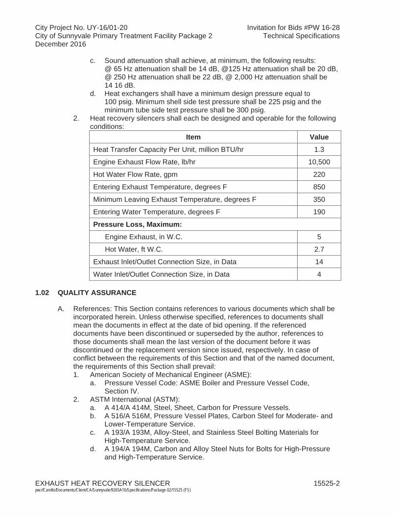
City Project No. UY-16/01-20 Invitation for Bids #PW 16-28City of Sunnyvale Primary Treatment Facility Package 2 Technical SpecificationsDecember 2016
EXHAUST HEAT RECOVERY SILENCER 15525-2 pw://Carollo/Documents/Client/CA/Sunnyvale/9265A10/Specifications/Package 02/15525 (FS)
c. Sound attenuation shall achieve, at minimum, the following results: @ 65 Hz attenuation shall be 14 dB, @125 Hz attenuation shall be 20 dB, @ 250 Hz attenuation shall be 22 dB, @ 2,000 Hz attenuation shall be 14 16 dB.
d. Heat exchangers shall have a minimum design pressure equal to100 psig. Minimum shell side test pressure shall be 225 psig and the minimum tube side test pressure shall be 300 psig.
2. Heat recovery silencers shall each be designed and operable for the following conditions:
Item ValueHeat Transfer Capacity Per Unit, million BTU/hr 1.3
Engine Exhaust Flow Rate, lb/hr 10,500
Hot Water Flow Rate, gpm 220
Entering Exhaust Temperature, degrees F 850
Minimum Leaving Exhaust Temperature, degrees F 350
Entering Water Temperature, degrees F 190
Pressure Loss, Maximum:Engine Exhaust, in W.C. 5
Hot Water, ft W.C. 2.7
Exhaust Inlet/Outlet Connection Size, in Data 14
Water Inlet/Outlet Connection Size, in Data 4
1.02 QUALITY ASSURANCE
A. References: This Section contains references to various documents which shall be incorporated herein. Unless otherwise specified, references to documents shall mean the documents in effect at the date of bid opening. If the referenced documents have been discontinued or superseded by the author, references to those documents shall mean the last version of the document before it was discontinued or the replacement version since issued, respectively. In case of conflict between the requirements of this Section and that of the named document, the requirements of this Section shall prevail:1. American Society of Mechanical Engineer (ASME):
a. Pressure Vessel Code: ASME Boiler and Pressure Vessel Code, Section IV.
2. ASTM International (ASTM):a. A 414/A 414M, Steel, Sheet, Carbon for Pressure Vessels. b. A 516/A 516M, Pressure Vessel Plates, Carbon Steel for Moderate- and
Lower-Temperature Service. c. A 193/A 193M, Alloy-Steel, and Stainless Steel Bolting Materials for
High-Temperature Service. d. A 194/A 194M, Carbon and Alloy Steel Nuts for Bolts for High-Pressure
and High-Temperature Service.

City Project No. UY-16/01-20 Invitation for Bids #PW 16-28City of Sunnyvale Primary Treatment Facility Package 2 Technical SpecificationsDecember 2016
EXHAUST HEAT RECOVERY SILENCER 15525-3 pw://Carollo/Documents/Client/CA/Sunnyvale/9265A10/Specifications/Package 02/15525 (FS)
1.03 SUBMITTALS
A. Submit in accordance with Section 01340, including the following information: 1. Manufacturer's type designation, catalog data sufficient to confirm the
electrical, mechanical, structural, instrumentation, and process control needed to support the equipment to operate as specified in these Contract Documents.This includes but is not limited to the efficiency, dimensions, weight, construction, seals, and installation details.
2. Anchor bolt and seismic calculations in accordance with Section 05190. 3. Performance calculations to demonstrate compliance with the listed
performance and design criteria. This includes but is not limited to pressure loss and heat transfer coefficients with and without additional fouling surface.
4. Operation and maintenance manual as specified in Section 01730. 5. Hydrostatic pressure test results.6. ASME pressure vessel calculations.7. Performance data for heat recovery silencer. Data includes pressure drop
across the silencer at maximum continuous rating on digester gas, and estimates of the sound attenuation at each octave band center frequency and the net (at the exhaust exit) exhaust noise at each octave band center frequency.
8. Pipe supports: a. Acknowledgement that products submitted meet requirements of
standards referenced.b. Manufacturer's installation instructions.c. Itemized list of wall sleeves, anchors, support devices, and all other items
related to pipe support system.d. Scaled drawings showing location, installation, material, loads and forces,
and deflection of all supports.e. Analyze each pipe system for all loads and forces on supports and their
reaction forces to the structure to which they are fastened.f. Support systems for piping systems over 200 degrees Fahrenheit
designed by the Contractor: Submit detail design calculations and scaled drawings prepared and signed by a registered Professional Engineer in the state of California.
1.04 ENVIRONMENTAL CONDITIONS
A. All equipment specified in this Section will be located outdoors. Project environmental conditions are specified in Section 01610.
PART 2 PRODUCTS
2.01 ACCEPTABLE MANUFACTURERS
A. Heat recovery silencers shall be shall be manufactured by Kickham Boilers, Maxim Silencers, or approved equal.
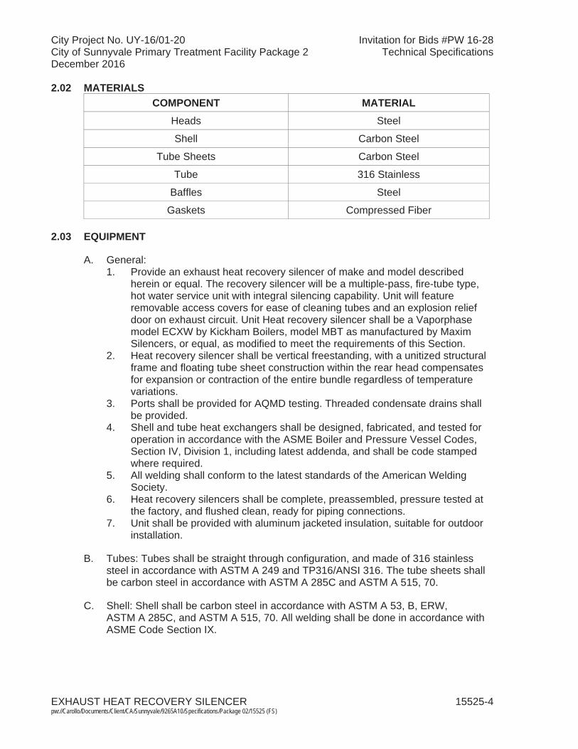
City Project No. UY-16/01-20 Invitation for Bids #PW 16-28City of Sunnyvale Primary Treatment Facility Package 2 Technical SpecificationsDecember 2016
EXHAUST HEAT RECOVERY SILENCER 15525-4 pw://Carollo/Documents/Client/CA/Sunnyvale/9265A10/Specifications/Package 02/15525 (FS)
2.02 MATERIALSCOMPONENT MATERIAL
Heads Steel
Shell Carbon Steel
Tube Sheets Carbon Steel
Tube 316 Stainless
Baffles Steel
Gaskets Compressed Fiber
2.03 EQUIPMENT
A. General:1. Provide an exhaust heat recovery silencer of make and model described
herein or equal. The recovery silencer will be a multiple-pass, fire-tube type, hot water service unit with integral silencing capability. Unit will feature removable access covers for ease of cleaning tubes and an explosion relief door on exhaust circuit. Unit Heat recovery silencer shall be a Vaporphase model ECXW by Kickham Boilers, model MBT as manufactured by MaximSilencers, or equal, as modified to meet the requirements of this Section.
2. Heat recovery silencer shall be vertical freestanding, with a unitized structural frame and floating tube sheet construction within the rear head compensates for expansion or contraction of the entire bundle regardless of temperature variations.
3. Ports shall be provided for AQMD testing. Threaded condensate drains shall be provided.
4. Shell and tube heat exchangers shall be designed, fabricated, and tested for operation in accordance with the ASME Boiler and Pressure Vessel Codes, Section IV, Division 1, including latest addenda, and shall be code stamped where required.
5. All welding shall conform to the latest standards of the American Welding Society.
6. Heat recovery silencers shall be complete, preassembled, pressure tested at the factory, and flushed clean, ready for piping connections.
7. Unit shall be provided with aluminum jacketed insulation, suitable for outdoor installation.
B. Tubes: Tubes shall be straight through configuration, and made of 316 stainless steel in accordance with ASTM A 249 and TP316/ANSI 316. The tube sheets shall be carbon steel in accordance with ASTM A 285C and ASTM A 515, 70.
C. Shell: Shell shall be carbon steel in accordance with ASTM A 53, B, ERW, ASTM A 285C, and ASTM A 515, 70. All welding shall be done in accordance with ASME Code Section IX.
City Project No. UY-16/01-20 Invitation for Bids #PW 16-28City of Sunnyvale Primary Treatment Facility Package 2 Technical SpecificationsDecember 2016
EXHAUST HEAT RECOVERY SILENCER 15525-5 pw://Carollo/Documents/Client/CA/Sunnyvale/9265A10/Specifications/Package 02/15525 (FS)
2.04 PRODUCT DATA
A. The following product data shall be provided in accordance with Section 01340: 1. Completed Manufacturer's Certificate of Installation and Functionality
Compliance in Section 01756. 2. Completed Manufacturer's Instruction Certification Form 11000-B.
B. Pipe Supports: 1. Supports capable of supporting the pipe for all service and testing conditions.
a. Provide 5 to 1 safety factor.2. Allow free expansion and contraction of the piping to prevent excessive stress
resulting from service and testing conditions or from weight transferred from the piping or attached equipment.
3. Design supports and hangers to allow for proper pitch of pipes.4. For hot air piping, design, materials of construction and installation of pipe
hangers, supports, guides, restraints, and anchors:a. ASME B31.1.
5. MSS SP-58 and MSS SP-69.6. Check all physical clearances between piping, support system, and structure.
a. Provide for vertical adjustment after erection.7. Support vertical pipe runs in pipe chases at base of riser.
a. Support pipes for lateral movement with clamps or brackets.8. Place hangers are to be installed on outside of pipe insulation.
a. Use a pipe covering protection saddle for insulated pipe at support point.b. Insulated piping over 1-1/2 inches: Provide a 12-inch length of
high-density perlite or high-density calcium silicate at saddle.
PART 3 EXECUTION
3.01 GENERAL
A. All equipment shall be aligned, connected, and installed at the locations specified and in accordance with the manufacturer's recommendations. The installation and initial operation of all components shall be certified as specified in Section 01756.
3.02 FACTORY TESTING
A. Heat exchangers shall be tested in accordance with the ASME Code, Section VIII, Division 1.
3.03 SHIPPING, STORAGE AND PROTECTION
A. All equipment delivery, storage, and handling shall be in accordance with Section 15050.
City Project No. UY-16/01-20 Invitation for Bids #PW 16-28City of Sunnyvale Primary Treatment Facility Package 2 Technical SpecificationsDecember 2016
EXHAUST HEAT RECOVERY SILENCER 15525-6 pw://Carollo/Documents/Client/CA/Sunnyvale/9265A10/Specifications/Package 02/15525 (FS)
3.04 FIELD TESTING
A. After the completion of installation, each unit specified in this Section shall be field tested in accordance with Section 01756 to demonstrate compliance with the performance requirements as specified. The manufacturer shall provide a factory-trained representative for a minimum of 8 hours to supervise initial operation and testing of all components.
B. After installation, heat recovery silencers shall be pressure tested at rated capacity to ensure proper operation. Pressure tests shall be performed on both the exhaust gas and heating water sides of the unit. Tests shall consist of cycling the pressure from zero to full rated capacity, held for 30 minutes, and then released. The cycle shall be successfully completed three successive times with no pressure in the alternate flow pate and no evidence of leakage.
3.05 TRAINING
A. During the commissioning period specified in Section 01756, the manufacturer shall provide a factory-trained person experienced in the operation and maintenance of the particular equipment specified herein for a period of at least 2 hours to train the plant operators and maintenance staff. Training shall conform to Section 01756.
END OF SECTION
City Project No. UY-16/01-20 Invitation for Bids #PW 16-28City of Sunnyvale Primary Treatment Facility Package 2 Technical SpecificationsDecember 2016
AIR CONDITIONING UNITS 15732-1 pw://Carollo/Documents/Client/CA/Sunnyvale/9265A10/Specifications/Package 02/15732 (FS)
SECTION 15732
AIR CONDITIONING UNITS
PART 1 GENERAL
1.01 SUMMARY
A. Section includes:1. Type 1- Packaged, Ductless split system air conditioning units.
B. Related sections:1. The Contract Documents are complementary; what is called for by one is as
binding as if called for by all.2. It is the Contractor's responsibility for scheduling and coordinating the Work of
subcontractors, suppliers, and other individuals or entities performing or furnishing any of Contractor's Work.
3. The following Sections are related to the Work described in this Section. This list of Related Sections is provided for convenience only and is not intended to excuse or otherwise diminish the duty of the Contractor to see that the completed Work complies accurately with the Contract Documents:a. Section 01340 - Shop Drawings, Product Data and Samples. b. Section 01060 - Regulatory Permits and Requirements.c. Section 01610 - Project Design Criteria.d. Section 01612 - Seismic Design Criteria.e. Section 01614 - Wind Design Criteria.f. Section 01756 - Commissioning and Process Start-Up.g. Section 01730 - Operation and Maintenance Data.h. Section 15050 - Common Work Results for Mechanical Equipment. i. Section 15082 - Piping Insulation.j. Section 15820 - Ductwork Accessories.k. Section 15936 - Instrumentation and Control Devices for HVAC. l. Section 15954 - Testing, Adjusting, and Balancing for HVAC. m. Section 16222 - Low Voltage Motors up to 500 Horsepower.
1.02 REFERENCES
A. Air-Conditioning, Heating, and Refrigeration Institute (AHRI):1. 210-240 - Performance Rating of Unitary Air-Conditioning and Air-Source Heat
Pump Equipment.2. 270 - Sound Rating of Outdoor Unitary Equipment.3. 340/360 - Performance Rating of Commercial and Industrial Unitary
Air-Conditioning and Heat Pump Equipment.
B. American Society of Heating, Refrigerating, and Air Conditioning Engineers (ASHRAE): 1. Standard 15 - Safety Standard for Refrigeration System.
City Project No. UY-16/01-20 Invitation for Bids #PW 16-28City of Sunnyvale Primary Treatment Facility Package 2 Technical SpecificationsDecember 2016
AIR CONDITIONING UNITS 15732-2 pw://Carollo/Documents/Client/CA/Sunnyvale/9265A10/Specifications/Package 02/15732 (FS)
2. Standard 52.2 - Methods of Testing General Ventilation Air-Cleaning Devices for Removal Efficiency by Particle Size.
3. Standard 62.1 - Ventilation for Acceptable Indoor Air Quality.
C. American National Standards Institute (ANSI):1. Z21.47 - Gas Fired Central Furnaces (except Direct Vent Central Furnaces)
with Addenda.
D. Air Movement and Control Association International, Inc. (AMCA): 1. 210 - Laboratory Methods for Testing Fans for Certified Aerodynamic
Performance Rating.
E. Federal Specification (FS):1. Standard 141 - Paint, Varnish, Lacquer, and Related Materials: Methods of
Inspection, Sampling and Testing.
F. National Electrical Code (NEC).
G. National Electrical Manufacturers Association (NEMA):1. 250 - Enclosures for Electrical Equipment (1000 V Maximum).
H. National Fire Protection Association (NFPA):1. 54 - National Fuel Gas Code.2. 90A - Standard for the Installation of Air Conditioning and Ventilating Systems.
I. National Roofing Contractors Association (NRCA).
J. Underwriters' Laboratories, Inc. (UL).
K. Title 24 of the California Code of Regulations (Title 24).
1.03 DEFINITIONS
A. NEMA Type 3R enclosure in accordance with NEMA 250.
1.04 SYSTEM DESCRIPTION
A. Design requirements:1. Seismic supports: Design support to meet criteria as specified in
Section 01612. 2. Wind supports: For exterior units, design supports that meet the criteria as
specified in Section 01614. 3. Electrical components: UL listed and met the design and installation
requirements of the NEC.4. Gas, water piping, drains, and venting: In accordance with building code,
mechanical code, and plumbing code a specified in Section 01060 and in accordance with NFPA 90A.
5. Motors: As specified in Section 16222. 6. Fans: Rated in accordance with AMCA 210.

City Project No. UY-16/01-20 Invitation for Bids #PW 16-28City of Sunnyvale Primary Treatment Facility Package 2 Technical SpecificationsDecember 2016
AIR CONDITIONING UNITS 15732-3 pw://Carollo/Documents/Client/CA/Sunnyvale/9265A10/Specifications/Package 02/15732 (FS)
7. Unit air conditioners: Rated in accordance with AHRI Standards 210-240 or 340/360 and AHRI 270. Conform to the latest version of ASHRAE 15.
8. Unit air conditioners with heating options: Certified in accordance with ANSI Z21.47.
9. Refrigerant: HFC R-410A. 10. For projects located in California, comply with energy efficiency requirements
of Title 24.
B. Performance requirements:1. As specified and as listed on the Air Conditioning Unit Schedule at the end of
this Section.2. Outdoor noise levels: Outdoor noise levels in the 8 octave band range as
measured in accordance with AHRI Standard 270 for unit air conditioners and split system condensers shall not exceed the following, noise levels measured in dB:
Unit NominalCapacity (Tons)
OCTAVE BANDS, hertz
63 125 250 500 1,000 2,000 4,000 8,000
2 to 5 64 70 71 74 74 71 67 61
6 79 85 78 74 71 73 66 59
7-1/2 to 10 64 70 73 79 82 78 74 67
12-1/2 and larger 84 88 84 83 84 78 72 683. Units shall be capable of starting and running at 125 degrees Fahrenheit
ambient outdoor air temperature and exceeding the maximum load criteria of AHRI Standard 210-240 or 340/360.
4. Cooling capacities and energy efficiency ratios: Provide units with the following cooling capacities and energy efficiency ratios (EER) as rated in accordance with AHRI 210-240 or 340/360 and 270, unless scheduled or specified otherwise:
Equipment TypeNet CoolingCap (Btuh) EER(1)
Air Cooled >65,000 and <135,000 11.2
Air Cooled >135,000 and < 240,000 11.0
Air Cooled >240,000 and < 760,000 10.0
Air Cooled > 760,000 9.7
Water Cooled >65,000 and <135,000 12.1
Water Cooled >135,000 and < 240,000 12.5
Water Cooled >240,000 and < 760,000 12.4
Water Cooled > 760,000 12.2
Note: (1) Deduct 0.2 from the required EERs for units with a heating section other than electric resistance
heat.

City Project No. UY-16/01-20 Invitation for Bids #PW 16-28City of Sunnyvale Primary Treatment Facility Package 2 Technical SpecificationsDecember 2016
AIR CONDITIONING UNITS 15732-4 pw://Carollo/Documents/Client/CA/Sunnyvale/9265A10/Specifications/Package 02/15732 (FS)
5. Units with heating capabilities: Meet or exceed the following efficiencies:a. Annual fuel utilization efficiency: 80 percent.b. Steady state efficiency: 80 percent.c. For projects located in California, California seasonal efficiency:
76.9 percent.6. Unit air flows for cooling: A minimum of 300 cubic feet per minute per ton but
not exceeding 500 cubic feet per minute per ton of cooling unless scheduled otherwise.
7. Air filters: 25 to 30 percent efficiency when rated in accordance with ASHRAE Standard 52.2.
C. Electrical and control system design:1. Design and supply necessary electrical power and control systems,
thermostats, components, and wiring to make a complete functioning system.
1.05 SUBMITTALS
A. Submit as specified in Section 01340.
B. Product data: 1. Shop drawings:
a. System layout, mechanical, electrical power, and control diagrams.b. Materials.c. Supports and seismic bracing calculations and details.d. Cut sheets on all primary and ancillary equipment.e. Proposed cutting and patching.f. Noise levels in 8 octave bands showing compliance with specified levels.g. For projects located in California, provide certification of compliance with
Title 24 energy efficiency standards and approval by the California Energy Commission.
C. Installation instructions.
D. Provide vendor operation and maintenance manual as specified in Section 01730.
E. Furnish bound sets of installation, operation, and maintenance instructions for each type of unit. Provide Manufacturer's Certificate of Source Testing as specified in Section 01756.
F. Provide Manufacturer's Certificate of Installation and Functionality Compliance as specified in Section 01756.
G. Manufacturer's warranties.
H. Operation and Maintenance Manual.
City Project No. UY-16/01-20 Invitation for Bids #PW 16-28City of Sunnyvale Primary Treatment Facility Package 2 Technical SpecificationsDecember 2016
AIR CONDITIONING UNITS 15732-5 pw://Carollo/Documents/Client/CA/Sunnyvale/9265A10/Specifications/Package 02/15732 (FS)
1.06 QUALITY ASSURANCE
A. Regulatory requirements:1. For projects located in California, comply with and be installed in accordance
with Title 24.
1.07 DELIVERY, STORAGE, AND HANDLING
A. Deliver units in 1 piece, factory assembled, piped, internally wired, charged with refrigerant and compressor oil, and tested.
B. Protect equipment from dust and atmospheric exposure:1. Provide temporary closures for equipment openings designed for airflow.
C. Protect equipment from dust and atmospheric exposure as recommended by the unit manufacturer:1. Provide temporary closures for equipment openings designed for airflow.
1.08 SITE CONDITIONS
A. As specified in Section 01610.
B. Units shall be capable of starting and operating in ambient temperatures as specified in this Section.
1.09 WARRANTY
A. Special warranties: From the date as defined in Section 01740. 1. 1-year warranty: All components.2. 5 years: For refrigerant compressors and closed or sealed refrigerant systems.3. 10 years: For gas fired heat exchangers.4. 10 years: For evaporator and condensing coils.
1.10 MAINTENANCE
A. Extra materials:1. Provide 2 extra sets of filters per unit installed.2. Provide 1 extra set of drive belts for each size belt system provided.
PART 2 PRODUCTS
2.01 TYPE 1- PACKAGED DUCTLESS SPLIT SYSTEM AIR CONDITIONING UNITS
A. Manufacturers: One of the following or equal:1. Carrier, Model 38 GVC/GVQ outdoor unit, 40 GVC/GVQ indoor unit. 2. Mitsubishi, equivalent model and size.
City Project No. UY-16/01-20 Invitation for Bids #PW 16-28City of Sunnyvale Primary Treatment Facility Package 2 Technical SpecificationsDecember 2016
AIR CONDITIONING UNITS 15732-6 pw://Carollo/Documents/Client/CA/Sunnyvale/9265A10/Specifications/Package 02/15732 (FS)
B. General:1. Indoor units: Direct-expansion, heat pump, wall-mounted fan coil. Unit shall be
complete with cooling/heating coil, fan, fan motor, piping connectors, electrical controls, microprocessor control system, and integral temperature sensing. Unit shall be furnished with integral wall mounting bracket and mounting hardware.
2. Outdoor condenser units: Air-cooled split system compressor sections suitable for on-the-ground, rooftop, or wall hung mounting. Units shall consist of a variable speed rotary compressor, an air-cooled coil, propeller-type draw-through outdoor fan, reversing valve, accumulator, metering devices, and control box. Units shall discharge horizontally. Units shall function as the outdoor component of an air-to-air heat pump system. Units shall be used in a refrigeration circuit matched to duct-free Air conditioning or heat pump fan coil units.
C. Compressors: 1. Fully hermetic variable speed rotary type, three phase, inverter driven, and
equipped with oil system, operating oil charge, and motor.2. Motor shall be NEMA rated Class F, suitable for operation in refrigerant
atmosphere.3. Installed on rubber vibration isolators.4. The inverter and compressor shall be protected against over temperature and
over current.
D. Fans:1. Indoor air fan:
a. Fan shall be tangential direct-drive blower type with air intake at the top of the unit and discharge at the bottom front. Automatic, motor-driven vertical air sweep shall be provided standard. Air sweep operation shall be user selectable. The vertical sweep may be adjusted (using the remote control) and the horizontal air direction may be set.
2. Outdoor condenser fan:a. Propeller type, direct drive, aluminum blades, dynamically balanced.b. Bearings: Permanently sealed ball bearing type and permanently
lubricated.
E. Coils:1. Evaporator and condenser coils: Seamless copper tubes with mechanically
bonded aluminum plate fins.2. A drip pan under the coil shall have a drain connection for pipe or hose
attachment to remove condensate. Condensate pan shall have internal trap.
F. Refrigerant components: Refrigerant circuit including:1. Accumulator and filter/drier.2. Expansion device.3. Flow control valves.4. Service and gauge connections on compressor suction and discharge, and
liquid lines to charge, evacuate, and contain refrigerant.5. Refrigerant lines shall be insulated. Provide insulation kit for refrigerant lines.
City Project No. UY-16/01-20 Invitation for Bids #PW 16-28City of Sunnyvale Primary Treatment Facility Package 2 Technical SpecificationsDecember 2016
AIR CONDITIONING UNITS 15732-7 pw://Carollo/Documents/Client/CA/Sunnyvale/9265A10/Specifications/Package 02/15732 (FS)
G. Controls and equipment safety features:1. Provide system controls for a complete functioning system:
a. Microprocessor-based control systems which shall control space temperature from 62 degrees Fahrenheit to 84 degrees Fahrenheit, determine optimum fan speed, and run self-diagnostics.
b. 3-speed fan motor.c. Automatic restart after power failure at the same operating conditions as
at failure.d. Temperature sensing control.e. Wireless infrared remote control.f. Automatic air sweep control to provide on or off activation of air sweep
louvers.g. Dehumidification mode controls.h. Fan-only operation to provide room air circulation when no cooling/heating
is required.i. Fan speed control shall be user-selectable: high, medium, low, or
microprocessor controlled automatic operation during all operating modes.j. The unit shall be protected against the following:
1) Indoor coil freeze up.2) Indoor coil high temperature protection. 3) Cold blow protection. 4) Compressor discharge over temperature protection.5) System low voltage protection.6) Compressor overload protection.7) Compressor over current protection.8) IPM module protection Space temperature setting.
H. Electrical:1. Provide for single external power connection of voltage and phases as
scheduled; control power wiring internal to the unit.
I. Unit casing:1. Indoor unit: Cabinet discharge and inlet grilles shall be attractively styled, high-
impact polystyrene. Cabinet shall be fully insulated for improved thermal and acoustic performance. Provided with:a. Filter rack for filters accessible through the front of the unit.b. Non-corrosive drain pan in accordance with ASHRAE Standard 62.1.c. Drain connection.d. Knockouts for power connections.e. Provide wall sleeve of galvanized steel coated similar to unit casing.
2. Outdoor Condenser Unit: Cabinet shall be constructed of galvanized steel, bonderized and coated with baked-enamel finish on inside and outside. Unit access panel should be removable with minimal screws and shall provide full access to the compressor, fan, and control components. Outdoor compartment shall be isolated and have an acoustic lining to assure quiet operation.
City Project No. UY-16/01-20 Invitation for Bids #PW 16-28City of Sunnyvale Primary Treatment Facility Package 2 Technical SpecificationsDecember 2016
AIR CONDITIONING UNITS 15732-8 pw://Carollo/Documents/Client/CA/Sunnyvale/9265A10/Specifications/Package 02/15732 (FS)
2.02 SOURCE QUALITY CONTROL
A. Completely factory test each unit in cooling and heating (if unit is supplied with heating option) modes including economizer operation. Coils and cooling system shall then be evacuated for 30 minutes prior to final charging of unit before shipment.
PART 3 EXECUTION
3.01 EXAMINATION
A. Examine and verify that Work is in condition to receive installation specified in this Section.1. Take measurements and verify dimensions to ascertain fit of installation.2. Ascertain structural sufficiency to support installation.3. Ascertain that supports and openings are correctly located; otherwise cut new
openings where required:a. Submit details of proposed cutting and patching.
4. Confirm specified thermostat or other controls are compatible with specified equipment.
B. Examine and verify structural details and sections indicated on the Drawings,ascertain adequacy, and determine conflicts in dimensions and clearances.
3.02 PREPARATION
A. Before installation, remove dust and debris from equipment and ducts.
B. During installation and until equipment is operated, protect equipment and ducts from dust and debris by covering openings with tape or plastic.
3.03 INSTALLATION
A. Observe applicable installation requirements as specified in Section 15050.
B. Anchoring and support:1. Provide anchoring and support designed in accordance with current
engineering practice for equipment and appurtenances by attaching or connecting to supporting members or by providing other supports.
C. Adjust alignment of ducts where necessary to resolve conflicts with architectural features or to resolve conflicts with the work of other trades.
D. Install and wire unit air conditioners, controls, and thermostats in accordance withmanufacturer's recommendations:1. Provide local disconnect switches.
E. Provide flexible duct and flexible piping connections at connections to unit air conditioners.
City Project No. UY-16/01-20 Invitation for Bids #PW 16-28City of Sunnyvale Primary Treatment Facility Package 2 Technical SpecificationsDecember 2016
AIR CONDITIONING UNITS 15732-9 pw://Carollo/Documents/Client/CA/Sunnyvale/9265A10/Specifications/Package 02/15732 (FS)
F. Install roof curb and unit as recommended by unit manufacturer.
G. Install NRCA approved flashing and counterflashing.
H. Provide venting in accordance with building code, mechanical code, and plumbing code as specified in Section 01060 and in accordance with NFPA 54.
I. Upon completion of installation, clean duct, and debris from ductwork, and equipment.
3.04 FIELD QUALITY CONTROL
A. Test equipment performance and balance equipment as specified in Section 15954.
3.05 COMMISSIONING AND PROCESS START-UP REQUIREMENTS
A. As specified in Section 01756 and this Section.
B. Manufacturer (each) services for each type of unit:1. Provide Manufacturer's Certificate of Source Testing.2. Provide Manufacturer's Certificate of Installation and Functionality Compliance.3. Manufacturer's Representative onsite requirements:
a. Installation: 1 trip, 2 days minimum each. b. Functional Testing: 1 trip, 1 day minimum each.
4. Training:a. Maintenance: 2 hours per session, 2 sessions. b. Operation: 1 hours per session, 2 sessions.
5. Process operational period:a. As required by Owner or Contractor.
3.06 SCHEDULES
A. Air Conditioning Unit Schedule.

AIR CONDITIONING UNITS 15732-10pw://Carollo/Documents/Client/CA/Sunnyvale/9265A10/Specifications/Package 02/15732 (FS)
City Project No. UY-16/01-20 Invitation for Bids #PW 16-28City of Sunnyvale Primary Treatment Facility Package 2 Technical SpecificationsDecember 2016
Con
ditio
ning
Uni
t Sch
edul
e
Equi
p.
No.
&
Type
Lo
catio
n
Evap
orat
orC
onde
nser
Hea
ting
Uni
t Po
wer
OSA
(c
fm)
Oth
er
Req
uire
men
ts
Sens
ible
(M
BH
)
Air
Fan
CFM
Fan
ESP,
"W
C
Inle
t D
B/W
B
(F)
Out
let
DB
/WB
(
F)In
let A
ir D
B (
F)G
as
Btu
/hr
Volts
/ Ph
ases
/ M
CA
See
Not
es a
t en
d of
Sc
hedu
le fo
r R
equi
rem
ents
AH
U-
212.
905
Type
1
Grit
and
Scr
eeni
ngs
Han
dlin
g Fa
cilit
y -
Ele
ctric
al
Roo
m
24,0
001,
400
Sta
ndar
d M
fgr
80/6
7 59
/54
95-
208-
230/
1/20
-20
,24
Not
es:
1.R
oof M
ount
ed S
ingl
e U
nit P
acka
ge.
2.B
ase/
floor
Mou
nted
Sin
gle
Uni
t Pac
kage
. 3.
Roo
f Mou
nted
Con
dens
er S
plit
Sys
tem
. 4.
Bas
e/flo
or M
ount
ed C
onde
nser
Spl
it S
yste
m.
5.S
ide
Sup
ply
Dis
char
ge C
onne
ctio
n.
6.S
ide
Ret
urn
Con
nect
ion.
7.
Bot
tom
Sup
ply
Dis
char
ge C
onne
ctio
n.
8.B
otto
m R
etur
n C
onne
ctio
n.
9.P
rovi
de E
lect
ric H
eatin
g.
10.
Pro
vide
Nat
ural
Gas
Hea
ting.
11
.P
rovi
de L
PG
Gas
Hea
ting.
12
.12
0Vo
lt C
ontro
l Vol
tage
. 13
.24
Volt
Con
trol V
olta
ge.
14.
Pro
vide
Indo
or A
ir H
andl
ing
Uni
t with
Dire
ct D
rive
Fan.
15
.P
rovi
de In
door
Air
Han
dlin
g U
nit w
ith B
elt D
rive
Fan
and
Adj
usta
ble
She
aves
.16
.P
rovi
de d
uct m
ount
ed F
an C
oil U
nit i
n ac
cord
ance
with
Sec
tion
1584
1si
zed
for s
ched
uled
con
ditio
ns.
17.
Prov
ide
Out
side
Air
Man
ual D
ampe
r. 18
.Pr
ovid
e E
cono
miz
er.
19.
Ther
mos
tat P
rovi
ded
by C
ontra
ctor
. 20
.Th
erm
osta
t Pro
vide
d by
AC
Uni
t Man
ufac
ture
r. 21
.C
ontro
l sys
tem
spe
cifie
d in
Sec
tion
1593
6.
22.
Wal
l mou
nted
uni
t with
sel
f-con
tain
ed c
ontro
ls.
23.
Incl
ude
serv
ice
optio
n w
ith re
turn
-air
smok
e de
tect
or s
enso
r to
be w
ired
in
field
to s
hut d
own
unit
upon
det
ectio
n of
sm
oke.
24
.P
rovi
de u
nit w
ith S
EE
R 1
6.
EN
D O
F S
EC
TIO
N
City Project No. UY-16/01-20 Invitation for Bids #PW 16-28City of Sunnyvale Primary Treatment Facility Package 2 Technical SpecificationsDecember 2016
HEAT PUMPS 15740-1 pw://Carollo/Documents/Client/CA/Sunnyvale/9265A10/Specifications/Package 02/15740 (FS)
SECTION 15740
HEAT PUMPS
PART 1 GENERAL
1.01 SUMMARY
A. Section includes:1. Packaged heat pumps.
B. Related sections:1. The Contract Documents are complementary; what is called for by one is as
binding as if called for by all.2. It is the Contractor's responsibility for scheduling and coordinating the Work of
subcontractors, suppliers, and other individuals or entities performing or furnishing any of Contractor's Work.
3. The following Sections are related to the Work described in this Section. This list of Related Sections is provided for convenience only and is not intended to excuse or otherwise diminish the duty of the Contractor to see that the completed Work complies accurately with the Contract Documents: a. Section 01060 - Regulatory Permits and Requirements.b. Section 01610 - Project Design Criteria.c. Section 01612 - Seismic Design Criteria.d. Section 01614 - Wind Design Criteria.e. Section 15050 - Common Work Results for Mechanical Equipment. f. Section 15082 - Piping Insulation.g. Section 15936 - Instrumentation and Control Devices for HVAC. h. Section 15954 - Testing, Adjusting, and Balancing for HVAC. i. Section 16050 - Common Work Results for Electrical. j. Section 16060 - Grounding and Bonding.k. Section 16075 - Identification for Electrical Systems. l. Section 16123 - 600-Volt or Less Wires and Cables.m. Section 16130 - Conduits.n. Section 16134 - Boxes.o. Section 16140 - Wiring Devices.p. Section 16222 - Low Voltage Motors up to 500 Horsepower.q. Section 16411 - Disconnect Switches.
1.02 REFERENCES
A. Air-Conditioning, Heating, and Refrigeration Institute (AHRI):1. 210-240 - Performance Rating of Unitary Air-Conditioning and Air-Source Heat
Pump Equipment.2. 270 - Sound Rating of Outdoor Unitary Equipment.
City Project No. UY-16/01-20 Invitation for Bids #PW 16-28City of Sunnyvale Primary Treatment Facility Package 2 Technical SpecificationsDecember 2016
HEAT PUMPS 15740-2 pw://Carollo/Documents/Client/CA/Sunnyvale/9265A10/Specifications/Package 02/15740 (FS)
B. Air Movement and Control Association International, Inc. (AMCA): 1. 210 - Laboratory Methods for Testing Fans for Certified Aerodynamic
Performance Rating.
C. American Society of Heating, Refrigerating, and Air-Conditioning Engineers (ASHRAE): 1. 15 - Safety Standard for Refrigeration Systems.2. 52.2 - Method of Testing General Ventilation Air-Cleaning Devices for
Removal Efficiency by Particle Size.3. 62.1 - Ventilation for Acceptable Indoor Air Quality.
D. Federal Specification (FS):1. Standard 141 - Paint, Varnish, Lacquer, and Related Materials: Methods of
Inspection, Sampling and Testing.
E. National Electrical Code (NEC).
F. National Electrical Manufacturers Association (NEMA):1. 250 - Enclosures for Electrical Equipment (1000 V Maximum).
G. National Fire Protection Association (NFPA):1. 54 - National Fuel Gas Code.2. 90A - Standard for the Installation of Air Conditioning and Ventilating Systems.
H. National Roofing Contractors Association (NRCA).
I. Title 24 of the California Code of Regulations (Title 24).
J. Underwriters' Laboratories, Inc. (UL).
1.03 DEFINITIONS
A. NEMA: 1. Type 1 enclosure in accordance with NEMA 250.2. Type 3R enclosure in accordance with NEMA 250.
1.04 SYSTEM DESCRIPTION
A. Design requirements:1. Seismic supports: Design supports to comply with the criteria specified in
Section 01612. 2. Wind supports: Design supports to comply with the criteria specified in
Section 01614. 3. Electrical components: UL listed and meeting the design and installation
requirements of the NEC.4. Water piping, drains, and venting: In accordance with building code,
mechanical code, and plumbing code as specified in Section 01060 and in accordance with NFPA 90A.
5. Fans supplied with heat pump units: Rated in accordance with AMCA 210.
City Project No. UY-16/01-20 Invitation for Bids #PW 16-28City of Sunnyvale Primary Treatment Facility Package 2 Technical SpecificationsDecember 2016
HEAT PUMPS 15740-3 pw://Carollo/Documents/Client/CA/Sunnyvale/9265A10/Specifications/Package 02/15740 (FS)
6. Unit heat pumps: Rated in accordance with AHRI Standards 210-240 and AHRI 270 and in accordance with the latest version of ASHRAE 15.
7. Roof curbs: Designed in accordance with NRCA standards.8. Insulation and adhesives: In accordance with NFPA 90A requirements for
flame spread and smoke generation.9. Refrigerant: HCFC.10. For projects located in California, comply with energy efficiency requirements
of Title 24.
B. Performance requirements:1. Performance requirements as specified and as scheduled on the Heat Pump
Schedule in this Section.2. Maximum sound power levels in the 8 octave band ranges, measured in
accordance with AHRI Standard 270:OCTAVE BANDS
Unit Nominal Capacity (Tons) 63 125 250 500 1,000 2,000 4,000 8,000
0 to 5 64 70 71 74 74 7871 67 67
7-1/2 to 10 65 70 73 80 84 78 73 65
12 and larger 84 88 84 83 84 78 72 683. Capable of starting and providing cooling from 45 to 125 degrees Fahrenheit
ambient outdoor air temperature and exceeding the maximum load criteria of AHRI Standard 210-240.
4. Capable of starting and providing heating at or above 0 degrees Fahrenheit outdoor ambient air temperature.
5. Minimum cooling and heating capacities, energy efficiency ratios (EER), and coefficient of performance (COP), as rated in accordance with AHRI 210-240and 270:
Nominal Capacity (Tons)
Standard cfm
Cooling Capacity
(Btuh) EER(3)
Heating HighTemperature(1)
Heating LowTemperature(2)
Capacity (Btuh) COP
Capacity (Btuh) COP
3 1,200 36,400 11.0 35,200 3.0 18,400 2.0
4 1,750 47,000 11.0 47,000 3.0 26,400 2.0
5 2,000 59,000 11.0 59,000 3.0 26,400 2.1
6 2,400 72,800 11.0 70,400 3.0 36.800 2.0
7-1/2 3,000 87,000 11.0 89,000 3.0 49,000 2.0
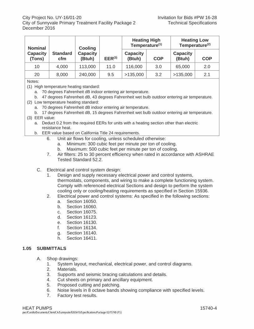
City Project No. UY-16/01-20 Invitation for Bids #PW 16-28City of Sunnyvale Primary Treatment Facility Package 2 Technical SpecificationsDecember 2016
HEAT PUMPS 15740-4 pw://Carollo/Documents/Client/CA/Sunnyvale/9265A10/Specifications/Package 02/15740 (FS)
Nominal Capacity (Tons)
Standard cfm
Cooling Capacity
(Btuh) EER(3)
Heating HighTemperature(1)
Heating LowTemperature(2)
Capacity (Btuh) COP
Capacity (Btuh) COP
10 4,000 113,000 11.0 116,000 3.0 65,000 2.0
20 8,000 240,000 9.5 >135,000 3.2 >135,000 2.1Notes:(1) High temperature heating standard:
a. 70 degrees Fahrenheit dB indoor entering air temperature.b. 47 degrees Fahrenheit dB, 43 degrees Fahrenheit wet bulb outdoor entering air temperature.
(2) Low temperature heating standard:a. 70 degrees Fahrenheit dB indoor entering air temperature.b. 17 degrees Fahrenheit dB, 15 degrees Fahrenheit wet bulb outdoor entering air temperature.
(3) EER value:a. Deduct 0.2 from the required EERs for units with a heating section other than electric
resistance heat.b. EER value based on California Title 24 requirements.
6. Unit air flows for cooling, unless scheduled otherwise:a. Minimum: 300 cubic feet per minute per ton of cooling.b. Maximum: 500 cubic feet per minute per ton of cooling.
7. Air filters: 25 to 30 percent efficiency when rated in accordance with ASHRAE Tested Standard 52.2.
C. Electrical and control system design:1. Design and supply necessary electrical power and control systems,
thermostats, components, and wiring to make a complete functioning system. Comply with referenced electrical Sections and design to perform the system cooling only or cooling/heating requirements as specified in Section 15936.
2. Electrical power and control systems: As specified in the following sections:a. Section 16050. b. Section 16060. c. Section 16075. d. Section 16123. e. Section 16130. f. Section 16134. g. Section 16140. h. Section 16411.
1.05 SUBMITTALS
A. Shop drawings:1. System layout, mechanical, electrical power, and control diagrams.2. Materials.3. Supports and seismic bracing calculations and details.4. Cut sheets on primary and ancillary equipment.5. Proposed cutting and patching.6. Noise levels in 8 octave bands showing compliance with specified levels.7. Factory test results.
City Project No. UY-16/01-20 Invitation for Bids #PW 16-28City of Sunnyvale Primary Treatment Facility Package 2 Technical SpecificationsDecember 2016
HEAT PUMPS 15740-5 pw://Carollo/Documents/Client/CA/Sunnyvale/9265A10/Specifications/Package 02/15740 (FS)
8. For projects in California, certification of compliance with Title 24 efficiency standards and approval by the California Energy Commission.
9. Anchor and anchor bolt sizing calculations in compliance with the requirements of Section 15050.
B. Operation and Maintenance Data.
C. Warranties.
1.06 DELIVERY, STORAGE, AND HANDLING
A. Deliver units in 1 piece, factory assembled, piped, internally wired, charged with refrigerant and compressor oil, and tested.
B. Protect equipment from dust and atmospheric exposure:1. Provide temporary closures for equipment openings designed for airflow.
1.07 SITE CONDITIONS
A. As specified in Section 01610.
1.08 WARRANTY
A. Special warranties: From the date of Acceptance of the project or date of beneficial use:1. 1-year warranty on all components.2. 5 years: For refrigerant compressors and closed or sealed refrigerant systems.3. 5 years: For electric heaters (if supplied).4. 5 years: For evaporator and condensing coils.
1.09 MAINTENANCE
A. Extra materials: Provide 2 extra sets of filters per unit installed.
PART 2 PRODUCTS
2.01 PACKAGED HEAT PUMPS
A. Manufacturers: One of the following or equal:1. Trane Series WC.2. Carrier, Series 50TC.3. Johnson controls, Series XP.4. All units supplied by same manufacturer.
B. Compressors:1. Fully hermetically sealed, high efficiency, reciprocating, or scroll type, with
internal and external vibration isolation.2. Equipped with high-pressure relief.
City Project No. UY-16/01-20 Invitation for Bids #PW 16-28City of Sunnyvale Primary Treatment Facility Package 2 Technical SpecificationsDecember 2016
HEAT PUMPS 15740-6 pw://Carollo/Documents/Client/CA/Sunnyvale/9265A10/Specifications/Package 02/15740 (FS)
C. Fans:1. Indoor air fan:
a. Direct or belt driven, forward curved, double inlet, centrifugal type, steel with corrosion resistant finish, statically and dynamically balanced.
b. Bearings: Permanently sealed ball bearing type and permanently lubricated.
c. Include an adjustable pitch motor pulley on belt drives.d. Where the condenser fan is 7.5 horsepower or larger, provide a variable
speed or 2 speed fan.2. Outdoor condenser fan:
a. Propeller type, direct drive, aluminum blades, dynamically balanced, and vertical discharge.
b. Bearings: Permanently sealed sleeve bearing type and permanently lubricated.
D. Coils:1. Evaporator and condenser coils: Seamless copper tubes with mechanically
bonded aluminum plate fins.2. Evaporator and condenser coils, internal piping, and appurtenances: Factory
applied phenol-formaldehyde thermosetting resinous coating (Heresite).
E. Refrigerant components: Refrigerant circuit including:1. Accumulator and filter/drier.2. Expansion device.3. Flow control valves.4. Circuit feed system.5. Strainer.6. Reversing valve.7. Service and gauge connections on compressor suction and discharge, and
liquid lines to charge, evacuate, and contain refrigerant.8. Insulated refrigerant lines: Insulate as specified in Section 15082.
F. Controls and equipment safety features:1. Provide system controls for a complete functioning system. Include:
a. Condenser fan controls.b. Evaporator fan controls.c. Motor contactors.d. Control circuit and any required transformer; voltage as scheduled or as
required to match specified room temperature controller.e. Manual reset circuit breakers.f. Electronic thermostat.g. 5-minute compressor cycle delay.h. Differential enthalpy economizer control.i. Check filter switch suitable for field connection remote alarm.j. 2-stage heating and cooling.k. Outdoor coil defrost system controls.l. Electric heater controls: When auxiliary electric heat is scheduled, provide
heat package controls to actuate auxiliary electric heat when mechanical heating is locked out.
City Project No. UY-16/01-20 Invitation for Bids #PW 16-28City of Sunnyvale Primary Treatment Facility Package 2 Technical SpecificationsDecember 2016
HEAT PUMPS 15740-7 pw://Carollo/Documents/Client/CA/Sunnyvale/9265A10/Specifications/Package 02/15740 (FS)
2. Equipment safety features:a. High-pressure switches.b. Compressor overtemperature and overcurrent.c. Loss of charge/low pressure switch.d. Freeze stat on evaporator.e. Lock out protection.f. When auxiliary electric heater is specified on Heat Pump Schedule
additional safety features:1) Heat limiters for primary and secondary overcurrent and thermal
protection:a) Automatic reset switches.b) Branch circuit protection.
3. Interface to building HVAC control system:a. Provide contacts and signals to operate unit with the building control
system as specified in Section 15936. b. If no building control system is specified in Section 15936, provide unit
interface devices and programmable electronic thermostat:1) Setpoint range of 60 to 90 degrees Fahrenheit with digital
temperature and setpoint indication.a) ON-OFF-AUTO air handler fan selector switch.b) HEAT-OFF-COOL unit selector switch or automatic switch over.c) 7-day programming schedule with at least 1 set back period per
day.d) Indicator lights for unit operating mode and unit failure.e) Wall mounted with insulated backing plate.f) Time delay for compressor restarts and for automatic switch
over.g) Provide with differential enthalpy economizer control when
economizer scheduled.
G. Electrical:1. Unit power and control wiring entering unit cabinet at 1 location.2. Provide 15 amp 120 volt, single phase, ground fault interrupter convenience
outlet at condenser unit; provide factory installed transformer, and independent fuse or breaker protection for outlet.
3. Provide power disconnect switch at each piece of unit; mount disconnect in NEMA Type 3R enclosure if exterior to unit; NEMA Type 1 enclosure if inside weather protected enclosure.
H. Unit casing:1. Manufactured of minimum 22 gauge galvanized steel, bonderized, corrosion
protected, and exterior coated with a baked enamel finish interior primer coated. Comply with Federal Test Method Standard 141 (Method 6061) 500-hour salt spray test.
2. Weatherproof design, reinforced and braced for maximum rigidity.3. Indoor air section compartment: Insulated with minimum 1/2-inch thick,
permanent, fireproof, odorless glass fiber material, and coated on the air side. Utilize aluminum foil face fiberglass insulation in the heating compartment when electrical heat is specified in the Heat Pump Schedule.
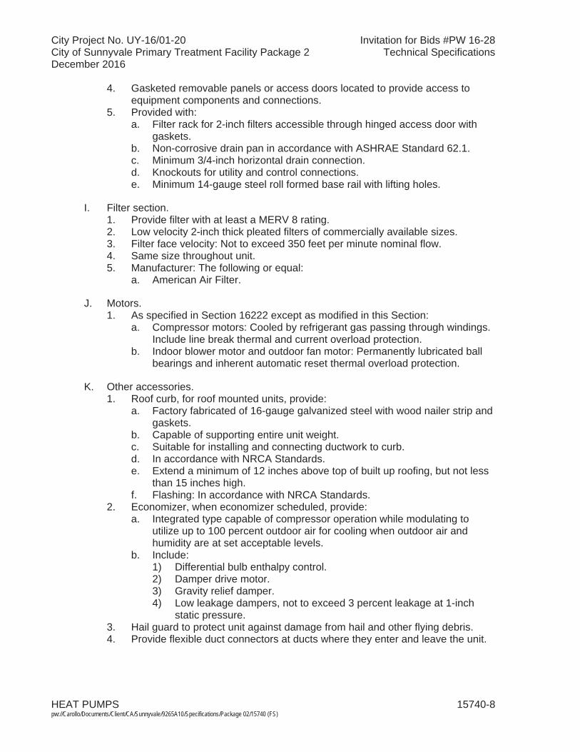
City Project No. UY-16/01-20 Invitation for Bids #PW 16-28City of Sunnyvale Primary Treatment Facility Package 2 Technical SpecificationsDecember 2016
HEAT PUMPS 15740-8 pw://Carollo/Documents/Client/CA/Sunnyvale/9265A10/Specifications/Package 02/15740 (FS)
4. Gasketed removable panels or access doors located to provide access to equipment components and connections.
5. Provided with:a. Filter rack for 2-inch filters accessible through hinged access door with
gaskets.b. Non-corrosive drain pan in accordance with ASHRAE Standard 62.1.c. Minimum 3/4-inch horizontal drain connection.d. Knockouts for utility and control connections.e. Minimum 14-gauge steel roll formed base rail with lifting holes.
I. Filter section.1. Provide filter with at least a MERV 8 rating.2. Low velocity 2-inch thick pleated filters of commercially available sizes.3. Filter face velocity: Not to exceed 350 feet per minute nominal flow.4. Same size throughout unit.5. Manufacturer: The following or equal:
a. American Air Filter.
J. Motors.1. As specified in Section 16222 except as modified in this Section:
a. Compressor motors: Cooled by refrigerant gas passing through windings. Include line break thermal and current overload protection.
b. Indoor blower motor and outdoor fan motor: Permanently lubricated ball bearings and inherent automatic reset thermal overload protection.
K. Other accessories.1. Roof curb, for roof mounted units, provide:
a. Factory fabricated of 16-gauge galvanized steel with wood nailer strip and gaskets.
b. Capable of supporting entire unit weight.c. Suitable for installing and connecting ductwork to curb.d. In accordance with NRCA Standards.e. Extend a minimum of 12 inches above top of built up roofing, but not less
than 15 inches high.f. Flashing: In accordance with NRCA Standards.
2. Economizer, when economizer scheduled, provide:a. Integrated type capable of compressor operation while modulating to
utilize up to 100 percent outdoor air for cooling when outdoor air and humidity are at set acceptable levels.
b. Include:1) Differential bulb enthalpy control.2) Damper drive motor.3) Gravity relief damper.4) Low leakage dampers, not to exceed 3 percent leakage at 1-inch
static pressure.3. Hail guard to protect unit against damage from hail and other flying debris.4. Provide flexible duct connectors at ducts where they enter and leave the unit.

City Project No. UY-16/01-20 Invitation for Bids #PW 16-28City of Sunnyvale Primary Treatment Facility Package 2 Technical SpecificationsDecember 2016
HEAT PUMPS 15740-9 pw://Carollo/Documents/Client/CA/Sunnyvale/9265A10/Specifications/Package 02/15740 (FS)
PART 3 EXECUTION
3.01 EXAMINATION
A. Examine and verify that Work is in condition to receive installation specified in this Section:1. Take measurements and verify dimensions to ascertain fit of installation.2. Ascertain structural sufficiency to support installation.3. Ascertain that supports and openings are correctly located; otherwise cut new
openings where required:a. Submit details of proposed cutting and patching.
4. Confirm specified thermostat or other controls are compatible with specified equipment.
B. Examine and verify structural details and sections indicated on the Drawings,ascertain adequacy, and determine conflicts in dimensions and clearances.
3.02 PREPARATION
A. Before installation remove dust and debris from equipment and ducts.
B. During installation and until equipment is operated, protect equipment and ducts from dust and debris by covering openings.
3.03 INSTALLATION
A. Comply with applicable installation requirements as specified in Section 15050.
B. Adjust alignment of ducts where necessary to resolve conflicts with architectural features or to resolve conflicts with the work of other trades.
C. Install and wire unit air conditioners, controls, and thermostats in accordance with manufacturer's recommendations.
D. Provide flexible duct and flexible piping connections as indicated on the Drawings atconnections to unit air conditioners.
E. Install roof curb and unit as recommended by unit manufacturer.
F. Install NRCA approved flashing and counterflashing.
G. Provide venting in accordance with building code, mechanical code, and plumbingcode as specified in Section 01060, and in accordance with NFPA 54.
H. Upon completion of installation, remove debris from ductwork and equipment and clean ducts.
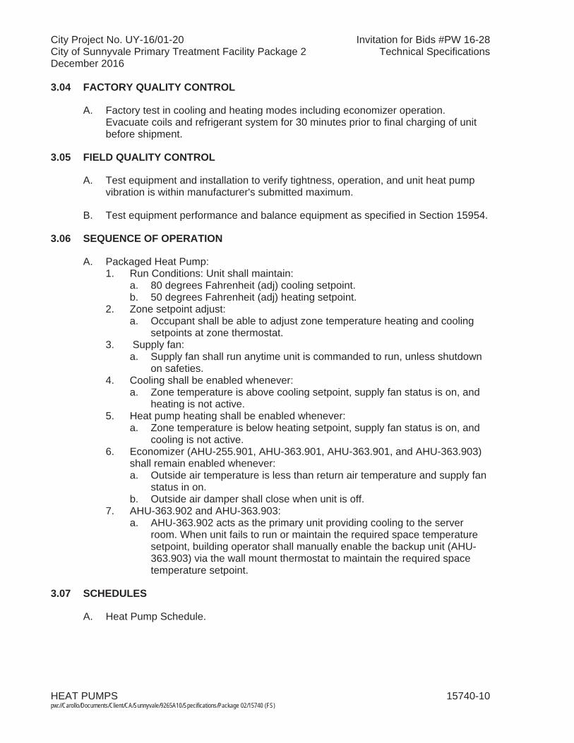
City Project No. UY-16/01-20 Invitation for Bids #PW 16-28City of Sunnyvale Primary Treatment Facility Package 2 Technical SpecificationsDecember 2016
HEAT PUMPS 15740-10pw://Carollo/Documents/Client/CA/Sunnyvale/9265A10/Specifications/Package 02/15740 (FS)
3.04 FACTORY QUALITY CONTROL
A. Factory test in cooling and heating modes including economizer operation. Evacuate coils and refrigerant system for 30 minutes prior to final charging of unit before shipment.
3.05 FIELD QUALITY CONTROL
A. Test equipment and installation to verify tightness, operation, and unit heat pump vibration is within manufacturer's submitted maximum.
B. Test equipment performance and balance equipment as specified in Section 15954.
3.06 SEQUENCE OF OPERATION
A. Packaged Heat Pump:1. Run Conditions: Unit shall maintain:
a. 80 degrees Fahrenheit (adj) cooling setpoint.b. 50 degrees Fahrenheit (adj) heating setpoint.
2. Zone setpoint adjust:a. Occupant shall be able to adjust zone temperature heating and cooling
setpoints at zone thermostat.3. Supply fan:
a. Supply fan shall run anytime unit is commanded to run, unless shutdown on safeties.
4. Cooling shall be enabled whenever:a. Zone temperature is above cooling setpoint, supply fan status is on, and
heating is not active.5. Heat pump heating shall be enabled whenever:
a. Zone temperature is below heating setpoint, supply fan status is on, and cooling is not active.
6. Economizer (AHU-255.901, AHU-363.901, AHU-363.901, and AHU-363.903) shall remain enabled whenever:a. Outside air temperature is less than return air temperature and supply fan
status in on.b. Outside air damper shall close when unit is off.
7. AHU-363.902 and AHU-363.903:a. AHU-363.902 acts as the primary unit providing cooling to the server
room. When unit fails to run or maintain the required space temperature setpoint, building operator shall manually enable the backup unit (AHU-363.903) via the wall mount thermostat to maintain the required space temperature setpoint.
3.07 SCHEDULES
A. Heat Pump Schedule.
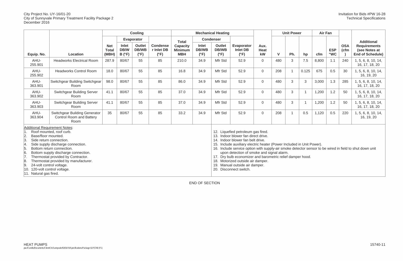
City Project No. UY-16/01-20 Invitation for Bids #PW 16-28City of Sunnyvale Primary Treatment Facility Package 2 Technical SpecificationsDecember 2016
HEAT PUMPS 15740-11pw://Carollo/Documents/Client/CA/Sunnyvale/9265A10/Specifications/Package 02/15740 (FS)
Equip. No. Location
Cooling Mechanical Heating
Aux. Heat kW
Unit Power Air Fan
OSA (cfm
)
Additional Requirements (see Notes at
End of Schedule)
Net Total
(MBH)
Evaporator
Condenser Inlet DB
( F)
Total Capacity Minimum
MBH
Condenser
Evaporator Inlet DB
( F) V Ph. hp cfm ESP"WC
Inlet DB/WB ( F)
Outlet DB/WB
( F)
Inlet DB/WB
( F)
Outlet DB/WB
( F)
AHU-255.901
Headworks Electrical Room 287.9 80/67 55 85 210.0 34.9 Mfr Std 52.9 0 480 3 7.5 8,800 1.1 240 1, 5, 6, 8, 10, 14,16, 17, 18, 20
AHU-255.902
Headworks Control Room 18.0 80/67 55 85 16.8 34.9 Mfr Std 52.9 0 208 1 0.125 675 0.5 30 1, 5, 6, 8, 10, 14,16, 19, 20
AHU-363.901
Switchgear Building Switchgear Room
98.0 80/67 55 85 86.0 34.9 Mfr Std 52.9 0 480 3 3 3,000 1.3 285 1, 5, 6, 8, 10, 14,16, 17, 18, 20
AHU-363.902
Switchgear Building Server Room
41.1 80/67 55 85 37.0 34.9 Mfr Std 52.9 0 480 3 1 1,200 1.2 50 1, 5, 6, 8, 10, 14,16, 17, 18, 20
AHU-363.903
Switchgear Building Server Room
41.1 80/67 55 85 37.0 34.9 Mfr Std 52.9 0 480 3 1 1,200 1.2 50 1, 5, 6, 8, 10, 14,16, 17, 18, 20
AHU-363.904
Switchgear Building Generator Control Room and Battery
Room
35 80/67 55 85 33.2 34.9 Mfr Std 52.9 0 208 1 0.5 1,120 0.5 220 1, 5, 6, 8, 10, 14,16, 19, 20
Additional Requirement Notes: 1. Roof mounted, roof curb. 2. Base/floor mounted.3. Side return connection.4. Side supply discharge connection. 5. Bottom return connection.6. Bottom supply discharge connection.7. Thermostat provided by Contractor.8. Thermostat provided by manufacturer.9. 24-volt control voltage.10. 120-volt control voltage.11. Natural gas fired.
12. Liquefied petroleum gas fired.13. Indoor blower fan direct drive.14. Indoor blower fan belt drive.15. Include auxiliary electric heater (Power Included in Unit Power).16. Include service option with supply-air smoke detector sensor to be wired in field to shut down unit
upon detection of smoke and signal alarm. 17. Dry bulb economizer and barometric relief damper hood.18. Motorized outside air damper.19. Manual outside air damper. 20. Disconnect switch.
END OF SECTION

City Project No. UY-16/01-20 Invitation for Bids #PW 16-28City of Sunnyvale Primary Treatment Facility Package 2 Technical SpecificationsDecember 2016
METAL DUCTS 15812-1 pw://Carollo/Documents/Client/CA/Sunnyvale/9265A10/Specifications/Package 02/15812 (FS)
SECTION 15812
METAL DUCTS
PART 1 GENERAL
1.01 SUMMARY
A. Section includes: Aluminum ductwork.
B. Related section:1. The Contract Documents are complementary; what is called for by one
is as binding as if called for by all.2. It is the Contractor's responsibility for scheduling and coordinating the
Work of subcontractors, suppliers, and other individuals or entities performing or furnishing any of Contractor's Work.
3. The following Sections are related to the Work described in this Section. This list of Related Sections is provided for convenience only and is not intended to excuse or otherwise diminish the duty of the Contractor to see that the completed Work complies accurately with the Contract Documents:a. Section 01340 - Shop Drawings, Product Data and Samples. b. Section 01612 - Seismic Design Criteria.c. Section 01756 - Commissioning and Process Start-Up.d. Section 15084 - Ductwork Insulation.e. Section 15820 - Ductwork Accessories.f. Section 15954 - Testing, Adjusting, and Balancing for HVAC.
1.02 REFERENCES
A. ASTM International (ASTM):1. B 209 - Standard Specification for Aluminum and Aluminum-Alloy
Sheet and Plate.
B. Sheet Metal and Air Conditioning Contractors' National Association (SMACNA): 1. HVAC Systems-Duct Design.2. Seismic Restraint Manual Guidelines for Mechanical Systems.
C. Underwriters Laboratories, Inc. (UL):1. 181A – Closure Systems for Use With Rigid Air Ducts.
1.03 SYSTEM DESCRIPTION
A. Design requirements:1. Custom design and fabricate metal ductwork for the applications
indicated on the Drawings and for the conditions specified.
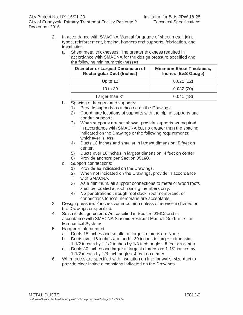
City Project No. UY-16/01-20 Invitation for Bids #PW 16-28City of Sunnyvale Primary Treatment Facility Package 2 Technical SpecificationsDecember 2016
METAL DUCTS 15812-2 pw://Carollo/Documents/Client/CA/Sunnyvale/9265A10/Specifications/Package 02/15812 (FS)
2. In accordance with SMACNA Manual for gauge of sheet metal, joint types, reinforcement, bracing, hangers and supports, fabrication, and installation.a. Sheet metal thicknesses: The greater thickness required in
accordance with SMACNA for the design pressure specified and the following minimum thicknesses:
Diameter or Largest Dimension of Rectangular Duct (Inches)
Minimum Sheet Thickness, Inches (B&S Gauge)
Up to 12 0.025 (22)
13 to 30 0.032 (20)
Larger than 31 0.040 (18)b. Spacing of hangers and supports:
1) Provide supports as indicated on the Drawings. 2) Coordinate locations of supports with the piping supports and
conduit supports.3) When supports are not shown, provide supports as required
in accordance with SMACNA but no greater than the spacing indicated on the Drawings or the following requirements; whichever is less.
4) Ducts 18 inches and smaller in largest dimension: 8 feet on center.
5) Ducts over 18 inches in largest dimension: 4 feet on center.6) Provide anchors per Section 05190.
c. Support connections:1) Provide as indicated on the Drawings. 2) When not indicated on the Drawings, provide in accordance
with SMACNA.3) As a minimum, all support connections to metal or wood roofs
shall be located at roof framing members only.4) No penetrations through roof deck, roof membrane, or
connections to roof membrane are acceptable.3. Design pressure: 2 inches water column unless otherwise indicated on
the Drawings or specified.4. Seismic design criteria: As specified in Section 01612 and in
accordance with SMACNA Seismic Restraint Manual Guidelines for Mechanical Systems.
5. Hanger reinforcement:a. Ducts 18 inches and smaller in largest dimension: None.b. Ducts over 18 inches and under 30 inches in largest dimension:
1-1/2 inches by 1-1/2 inches by 1/8-inch angles, 8 feet on center.c. Ducts 30 inches and larger in largest dimension: 1-1/2 inches by
1-1/2 inches by 1/8-inch angles, 4 feet on center.6. When ducts are specified with insulation on interior walls, size duct to
provide clear inside dimensions indicated on the Drawings.
City Project No. UY-16/01-20 Invitation for Bids #PW 16-28City of Sunnyvale Primary Treatment Facility Package 2 Technical SpecificationsDecember 2016
METAL DUCTS 15812-3 pw://Carollo/Documents/Client/CA/Sunnyvale/9265A10/Specifications/Package 02/15812 (FS)
B. Miscellaneous design details:1. Changes in duct size:
a. Use uniformly tapering sections.b. Taper not more than 1 inch in 5 inches of run unless otherwise
indicated on the Drawings. 2. Bends: With the exception of miter bends, design bends with inside
radii equal to duct width or diameter:a. Install turning vanes at miter bends.
3. Duct sleeves: Install duct sleeve when ducts pass through concrete or masonry walls, slabs, or ceilings.
4. Access openings: Install in locations that allow access to dampers, fusible links, controllers, and similar devices.
5. Flexible connections: Install at connections to air handling equipment and at locations indicated on the Drawings.
1.04 SUBMITTALS
A. Submit as specified in Section 01340.
B. Product data:1. Duct and component material and details of construction.2. System layout including floor and wall penetrations.3. Supports and anchoring details.4. Components used in the duct system including turning vanes,
dampers, flexible connections, and access doors.
C. Design data - seismic design calculations.1. Design calculations for duct construction as specified in Section 01612
and in accordance with SMACNA.2. Concrete anchor calculations as specified in Section 05190.
D. Provide Manufacturer's Certificate of Source Testing as specified in Section 01756.
PART 2 PRODUCTS
2.01 MATERIALS
A. Ducts: Aluminum alloy 3003 H14 in accordance with ASTM B 209.
B. Flexible connectors: As specified in Section 15820.
C. Turning vanes: Match duct material.
D. Reinforcing: Formed or extruded aluminum angles.
E. Ductwork insulation: As specified in Section 15084.

City Project No. UY-16/01-20 Invitation for Bids #PW 16-28City of Sunnyvale Primary Treatment Facility Package 2 Technical SpecificationsDecember 2016
METAL DUCTS 15812-4 pw://Carollo/Documents/Client/CA/Sunnyvale/9265A10/Specifications/Package 02/15812 (FS)
2.02 COMPONENTS
A. Duct sleeves:1. Sleeve flanges: 4 inches wide.2. Size: 2 inches larger than the duct or duct with external insulation.
B. Access openings:1. Size: 2 inches less than duct size.2. Doors:
a. Gauge not less than duct sheet.b. Provide continuous hinge and latch on outside.
3. Gasket: Along door periphery.4. Visual panel: 1/8-inch thick, clear plexiglass.
C. Turning vanes:1. Material: Same as ductwork.2. Type:
a. Single-blade vanes for duct widths less than 36 inches.b. Airfoil type vanes for duct widths of 36 inches and greater:
1) No trailing edge.3. Mounted in side rails.4. Provide turning vanes for square-turn elbows and splitters.5. Size: 2-inch blades for ducts up to 18 inches, 4-1/2-inch blades for
larger ducts.
D. Splitter dampers: Provide at branch take-offs where necessary for balancing system.
E. Extractors:1. Components:
a. Synchronized steel curved blades.b. Heavy side rails.c. Screw operator.
2. Provide extractors at take-off from main supply duct adjacent to diffusers, registers, or grilles where splitter is not used.
2.03 FABRICATION
A. Fabricate ductwork to the configuration and dimensions indicated on the Drawings.
B. Dimensions indicate net free area. Increase duct dimensions by thickness of insulation when internal insulation is specified.
C. Do not utilize S clips, duct tape, or externally applied mastic on medium pressure duct systems.
D. Do not use snap lock seams.
E. Provide flexible duct connectors at all connections to fans and other air movement equipment.
City Project No. UY-16/01-20 Invitation for Bids #PW 16-28City of Sunnyvale Primary Treatment Facility Package 2 Technical SpecificationsDecember 2016
METAL DUCTS 15812-5 pw://Carollo/Documents/Client/CA/Sunnyvale/9265A10/Specifications/Package 02/15812 (FS)
PART 3 EXECUTION
3.01 EXAMINATION
A. Examine and verify that Work is in condition to receive metallic ductwork as specified in this Section:1. Take measurements and verify dimensions on shop drawings to verify
fit of installation.2. Verify that supports and openings are correctly located.
B. Examine and verify structural details and determine conflicts in dimensions and clearances.
3.02 INSTALLATION
A. Cover ductwork openings with tape, plastic, or sheet metal to reduce the amount of dust or debris which may collect in the system at each of the following times:1. At the time of rough installation.2. During storage on the construction site.3. Until final start-up of the heating and cooling equipment.
B. Before installation remove dust and debris from ducts.
C. Adjust duct alignment where necessary to resolve conflicts with architectural features or to resolve conflicts with the work of other trades.
D. Install ductwork to provide a system free of buckling, warping, or vibration.
E. Hangers:1. Install hangers as indicated on the Drawings. 2. When hangers are not detailed, conform to SMACNA HVAC System
Duct Design and Seismic Restraint Manual standards and the following requirements:a. Rectangular ducts concealed in ceiling spaces:
1) Use metal strap hangers.2) Fasten to sides of duct with 2 screws.3) Fasten to bottom of duct with 1 screw.
b. Rectangular ducts in exposed areas:1) Install shelf angle trapeze hangers or Unistrut type hangers.2) Install sway bracing as required by seismic calculations,
minimum 1 brace at right angle to each duct run.c. Round ducts in exposed areas:
1) Install 2 half-round bands with rods bolted to panels.2) Install sway bracing as required by seismic calculations,
minimum 1 brace at right angle to each duct run.3. Flexible connections: As specified in Section 15820.
F. Provide closed-cell neoprene gaskets at flanged joints.
G. Tapes and mastics used to seal ductwork shall be listed and labeled in accordance with UL 181A and shall be marked.
City Project No. UY-16/01-20 Invitation for Bids #PW 16-28City of Sunnyvale Primary Treatment Facility Package 2 Technical SpecificationsDecember 2016
METAL DUCTS 15812-6 pw://Carollo/Documents/Client/CA/Sunnyvale/9265A10/Specifications/Package 02/15812 (FS)
3.03 FIELD QUALITY CONTROL
A. Inspect ductwork under operating conditions:1. Correct audible leaks and leaks that can be felt with the hand.
B. Test and balance ducting systems as specified in Section 15954.
END OF SECTION
City Project No. UY-16/01-20 Invitation for Bids #PW 16-28City of Sunnyvale Primary Treatment Facility Package 2 Technical SpecificationsDecember 2016
FIBERGLASS REINFORCED PLASTIC DUCTS 15814-1 pw://Carollo/Documents/Client/CA/Sunnyvale/9265A10/Specifications/Package 02/15814 (FS)
SECTION 15814
FIBERGLASS REINFORCED PLASTIC DUCTS
PART 1 GENERAL
1.01 SUMMARY
A. Section includes: Fiberglass reinforced plastic ductwork system, consisting of ducting and including fasteners, field joints, expansion joints, and supports. FRP dampers are specified in relevant paragraphs of Section 15820 Ductwork Accessories.
B. Related sections:1. The Contract Documents are complementary; what is called for by one is as
binding as if called for by all.2. It is the Contractor's responsibility for scheduling and coordinating the Work of
subcontractors, suppliers, and other individuals or entities performing or furnishing any of Contractor's Work.
3. The following Sections are related to the Work described in this Section. This list of Related Sections is provided for convenience only and is not intended to excuse or otherwise diminish the duty of the Contractor to see that the completed Work complies accurately with the Contract Documents:a. Section 06608 - Fiberglass Reinforced Plastic.b. Section 15820 – Ductwork Accessories.
1.02 REFERENCES
A. Sheet Metal and Air Conditioning Contractors' National Association (SMACNA).
B. American Society of Mechanical Engineers (ASME):1. B16.5 - Pipe Flanges and Flanged Fittings:
C. ASTM International (ASTM):1. C 582 - Standard Specification for Contact-Molded Reinforced Thermosetting
Plastic (RTP) Laminates for Corrosion-Resistant Equipment.2. D 792 - Standard Test Methods for Density and Specific Gravity (Relative
Density) of Plastics by Displacement.3. D 2105 - Standard Test Method for Longitudinal Tensile Properties of
Fiberglass (Glass-Fiber-Reinforced Thermosetting-Resin) Pipe and Tube.4. D 2344 - Standard Test Method for Short-Beam Strength of Polymer Matrix
Composite Materials and Their Laminates.5. D 2412 - Standard Test Method for Determination of External Loading
Characteristics of Plastic Pipe by Parallel-Plate Loading.6. D 2996 - Standard Specification for Filament Wound Fiberglass ((Glass Fiber
Reinforced Thermosetting Resin) Pipe.7. D 3839 - Standard Guide for Underground Installation of Fiberglass (Glass
Fiber Reinforced Thermosetting Resin) Pipe.8. D 3982 - Standard for specification for Contact-Molded duct.
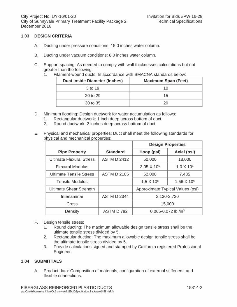
City Project No. UY-16/01-20 Invitation for Bids #PW 16-28City of Sunnyvale Primary Treatment Facility Package 2 Technical SpecificationsDecember 2016
FIBERGLASS REINFORCED PLASTIC DUCTS 15814-2 pw://Carollo/Documents/Client/CA/Sunnyvale/9265A10/Specifications/Package 02/15814 (FS)
1.03 DESIGN CRITERIA
A. Ducting under pressure conditions: 15.0 inches water column.
B. Ducting under vacuum conditions: 8.0 inches water column.
C. Support spacing: As needed to comply with wall thicknesses calculations but not greater than the following:1. Filament-wound ducts: In accordance with SMACNA standards below:
Duct Inside Diameter (Inches) Maximum Span (Feet)
3 to 19 10
20 to 29 15
30 to 35 20
D. Minimum flooding: Design ductwork for water accumulation as follows:1. Rectangular ductwork: 1 inch deep across bottom of duct.2. Round ductwork: 2 inches deep across bottom of duct.
E. Physical and mechanical properties: Duct shall meet the following standards for physical and mechanical properties:
Pipe Property Standard
Design Properties
Hoop (psi) Axial (psi)Ultimate Flexural Stress ASTM D 2412 50,000 18,000
Flexural Modulus 3.05 X 10⁶ 1.0 X 10⁶
Ultimate Tensile Stress ASTM D 2105 52,000 7,485
Tensile Modulus 1.5 X 10⁶ 1.56 X 10⁶
Ultimate Shear Strength Approximate Typical Values (psi)
Interlaminar ASTM D 2344 2,130-2,730
Cross 15,000
Density ASTM D 792 0.065-0.072 lb./in3
F. Design tensile stress:1. Round ducting: The maximum allowable design tensile stress shall be the
ultimate tensile stress divided by 5.2. Rectangular ducting: The maximum allowable design tensile stress shall be
the ultimate tensile stress divided by 5. 3. Provide calculations signed and stamped by California registered Professional
Engineer.
1.04 SUBMITTALS
A. Product data: Composition of materials, configuration of external stiffeners, and flexible connections.
City Project No. UY-16/01-20 Invitation for Bids #PW 16-28City of Sunnyvale Primary Treatment Facility Package 2 Technical SpecificationsDecember 2016
FIBERGLASS REINFORCED PLASTIC DUCTS 15814-3 pw://Carollo/Documents/Client/CA/Sunnyvale/9265A10/Specifications/Package 02/15814 (FS)
B. Shop drawings:1. Drawings showing ductwork layout, dimensions, joint types, and support
locations.2. Locations of external stiffeners and expansion joints.3. Fabrication details.4. Support locations, types, and details. Provide calculations signed and stamped
by California registered Professional Engineer.
C. Calculations:1. Wall thickness calculations based upon design criteria.2. Stresses and reaction loads at supports.3. Provide calculations signed and stamped by California registered Professional
Engineer.
D. Manufacturer's Installation Instructions.
1.05 QUALITY ASSURANCE
A. Qualification of ducting manufacturer: Manufacturer with experienced personnel, physical facilities, and management capacity sufficient to produce custom-made, corrosion resistant fiberglass reinforced plastic products of quality and size specified with a minimum of 10 years in continuous operation manufacturing FRP duct and pipe systems for odor control. Provide 10 similar installations equal or larger as references that are currently in operation.
B. Submit test results as specified in Section 06608 verifying that ductwork meetsstandards specified.
PART 2 PRODUCTS
2.01 MANUFACTURERS
A. Fiberglass reinforced plastic ductwork: One of the following or approved equal:1. Daniel Mechanical. 2. Fibercast.3. Spunstrand.
2.02 DUCTWORK MATERIALS
A. As specified in applicable portions of Section 06608.
B. Minimum corrosion liner:1. Interior surfacing "C" or Nexus veil as specified for the service environment.2. Exterior surfacing: "C" or "A" veil. The exterior layer shall be UV resistant.3. Remainder 1-1/2 ounce per square foot mat to total minimum thickness of
0.096 inches on surface exposed to the service environment.
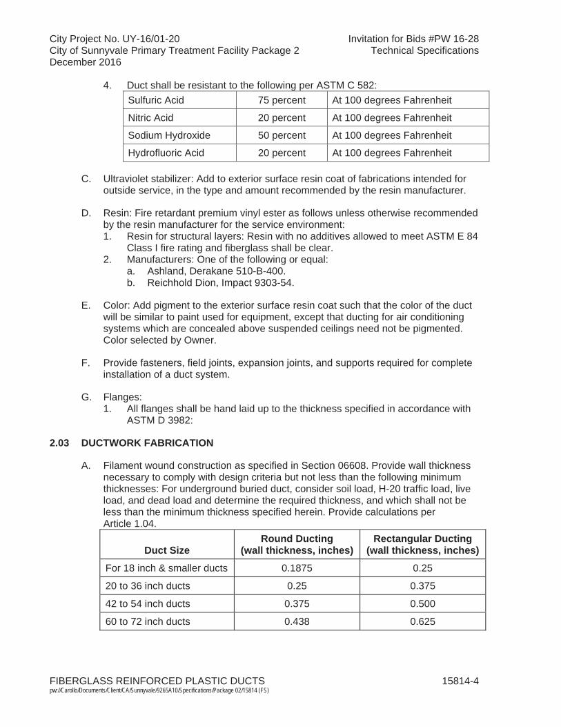
City Project No. UY-16/01-20 Invitation for Bids #PW 16-28City of Sunnyvale Primary Treatment Facility Package 2 Technical SpecificationsDecember 2016
FIBERGLASS REINFORCED PLASTIC DUCTS 15814-4 pw://Carollo/Documents/Client/CA/Sunnyvale/9265A10/Specifications/Package 02/15814 (FS)
4. Duct shall be resistant to the following per ASTM C 582:Sulfuric Acid 75 percent At 100 degrees Fahrenheit
Nitric Acid 20 percent At 100 degrees Fahrenheit
Sodium Hydroxide 50 percent At 100 degrees Fahrenheit
Hydrofluoric Acid 20 percent At 100 degrees Fahrenheit
C. Ultraviolet stabilizer: Add to exterior surface resin coat of fabrications intended for outside service, in the type and amount recommended by the resin manufacturer.
D. Resin: Fire retardant premium vinyl ester as follows unless otherwise recommended by the resin manufacturer for the service environment:1. Resin for structural layers: Resin with no additives allowed to meet ASTM E 84
Class I fire rating and fiberglass shall be clear. 2. Manufacturers: One of the following or equal:
a. Ashland, Derakane 510-B-400. b. Reichhold Dion, Impact 9303-54.
E. Color: Add pigment to the exterior surface resin coat such that the color of the duct will be similar to paint used for equipment, except that ducting for air conditioningsystems which are concealed above suspended ceilings need not be pigmented. Color selected by Owner.
F. Provide fasteners, field joints, expansion joints, and supports required for completeinstallation of a duct system.
G. Flanges:1. All flanges shall be hand laid up to the thickness specified in accordance with
ASTM D 3982:
2.03 DUCTWORK FABRICATION
A. Filament wound construction as specified in Section 06608. Provide wall thickness necessary to comply with design criteria but not less than the following minimum thicknesses: For underground buried duct, consider soil load, H-20 traffic load, live load, and dead load and determine the required thickness, and which shall not be less than the minimum thickness specified herein. Provide calculations per Article 1.04.
Duct Size Round Ducting
(wall thickness, inches)Rectangular Ducting
(wall thickness, inches)
For 18 inch & smaller ducts 0.1875 0.25
20 to 36 inch ducts 0.25 0.375
42 to 54 inch ducts 0.375 0.500
60 to 72 inch ducts 0.438 0.625

City Project No. UY-16/01-20 Invitation for Bids #PW 16-28City of Sunnyvale Primary Treatment Facility Package 2 Technical SpecificationsDecember 2016
FIBERGLASS REINFORCED PLASTIC DUCTS 15814-5 pw://Carollo/Documents/Client/CA/Sunnyvale/9265A10/Specifications/Package 02/15814 (FS)
B. Fittings:1. Type: Hand lay-up contact molded.2. Resin: Identical to and with same strength as resin used for FRP ductwork3. Wall thickness: At least equal to the thickness of the thickest adjacent ducting.4. Internal diameter: Equal to the adjacent duct.5. Tolerance:
a. Angles for all fittings shall be within 1 degree for up to 30-inch diameter duct.
b. Angles for all fittings shall be within 1/2 degree for over 30-inch diameter and above duct.
C. Joints:1. Flanged:
a. Flanged in accordance with ASTM D 3982. b. Flanged joints shall be provided at the following locations:
1) At each damper and each item of equipment to facilitate disassembly.
2) At each change in material.3) Where indicated on the Drawings.
c. Gaskets for flanged joints: 1/8-inch neoprene over full flange face.d. Bolt nuts and washers: Type 316 stainless steel.
2. Butt and strap welded:a. Field butt and strap welded joints shall be provided at the following
locations:1) 12 inches from any increasing or decreasing cross-section of pipe.2) Where the pipe to be joined has the same diameter.
b. Thickness of butt and strap joint overlays: At least equal to the thickness of the thickest adjacent duct.
c. Field weld kits:1) All necessary fiberglass and reinforcing material shall be supplied
pre-cut and individually packaged for each joint.2) Bulk Glass rolls will not be acceptable.
2.04 FLEXIBLE CONNECTIONS
A. Manufacturers: One of following or approved equal:1. Daniel mechanical. 2. Belmont.3. Garlock.
B. Materials: Minimum 14-ounce neoprene encased canvas, flameproof, suitable for use in service environment.
C. Design:1. Number of volutes needed to satisfy axial and lateral movement requirements.2. Airtight at pressures encountered.
D. Elastomeric sleeves or boots may be used for direct expansion joints on low pressure and low vacuum systems.

City Project No. UY-16/01-20 Invitation for Bids #PW 16-28City of Sunnyvale Primary Treatment Facility Package 2 Technical SpecificationsDecember 2016
FIBERGLASS REINFORCED PLASTIC DUCTS 15814-6 pw://Carollo/Documents/Client/CA/Sunnyvale/9265A10/Specifications/Package 02/15814 (FS)
2.05 DUCT SUPPORTS
A. Provide duct supports as indicated on the Drawings.
B. When duct supports are not indicated on the Drawings provide supports and seismic bracing in accordance with the SMACNA Design Manual.
2.06 NON-METALLIC FLEXIBLE DUCTING
A. Where required, provide non-metallic flexible ducting:1. Manufacturers: One of the following or equal:
a. Masterduct, Master-Clip Vinton.2. Characteristics:
a. Reinforcement: Steel wire reinforcement.b. Compressibility: 1:6.c. Hose wall: Viton-coated polyester fabric.
PART 3 EXECUTION
3.01 INSTALLATION
A. Cover ductwork openings with tape, plastic, or sheet metal to reduce the amount of dust or debris which may collect in the system at each of the following times:1. At the time of rough installation.2. During storage on the construction site.3. Until final start-up of the heating and cooling equipment.
B. Before installation remove dust and debris from ducts.
C. Install products in accordance with shop drawings and manufacturer's instructions. Drawings indicate general routing only and shall be modified as necessary.
D. The duct manufacturer shall supply a minimum of 2 days of training for the contractor to ensure proper installation of duct. The duct manufacturer shall provide a final inspection and document approval with Engineer.
E. Coat ductwork per Section 09960.
3.02 FLEXIBLE CONNECTIONS
A. Install flexible connections between ducting and rotating equipment.
B. Restrain flexible connections by control rods.
END OF SECTION
City Project No. UY-16/01-20 Invitation for Bids #PW 16-28City of Sunnyvale Primary Treatment Facility Package 2 Technical SpecificationsDecember 2016
DUCTWORK ACCESSORIES 15820-1 pw://Carollo/Documents/Client/CA/Sunnyvale/9265A10/Specifications/Package 02/15820 (FS)
SECTION 15820
DUCTWORK ACCESSORIES
PART 1 GENERAL
1.01 SUMMARY
A. Section includes:1. Dampers and damper operators.2. Diffusers, grilles, and registers.3. Screens.4. Flexible duct connectors.5. Other ductwork accessories.
B. Related sections:1. The Contract Documents are complementary; what is called for by one is as
binding as if called for by all.2. It is the Contractor's responsibility for scheduling and coordinating the Work of
subcontractors, suppliers, and other individuals or entities performing or furnishing any of Contractor's Work.
3. The following Sections are related to the Work described in this Section. This list of Related Sections is provided for convenience only and is not intended to excuse or otherwise diminish the duty of the Contractor to see that the completed Work complies accurately with the Contract Documents:a. Section 01340 - Shop Drawings, Product Data and Samples. b. Section 01756 - Commissioning and Process Start-Up.c. Section 15954 - Testing, Adjusting, and Balancing for HVAC.
1.02 REFERENCES
A. National Electrical Manufacturers Association (NEMA):1. 250 - Enclosures for Electrical Equipment (1000 V Maximum).
B. National Fire Protection Association (NFPA):1. 90B - Standard for the Installation of Warm Air Heating and Air-Conditioning
Systems.2. 255 - Standard Method of Test of Surface Burning Characteristics of Building
Materials.
C. Uniform Building Code (UBC).
D. Underwriters Laboratories, Inc. (UL):1. 555 - Fire Dampers.2. 555S - Smoke Dampers.
City Project No. UY-16/01-20 Invitation for Bids #PW 16-28City of Sunnyvale Primary Treatment Facility Package 2 Technical SpecificationsDecember 2016
DUCTWORK ACCESSORIES 15820-2 pw://Carollo/Documents/Client/CA/Sunnyvale/9265A10/Specifications/Package 02/15820 (FS)
1.03 DEFINITIONS
A. Dampers, diffusers, grilles, and registers specified are indicated on the Drawings by the abbreviations listed below. Each abbreviation is followed by a hyphen and a number to designate the required style of unit:1. BD: Balancing Damper.2. BDD: Backdraft Damper.3. DG: Door Grille.4. FD: Fire Damper.5. FL: Flexible Duct Connector.6. RR: Return Register or Grille.7. SD: Smoke Damper.8. SFD: Smoke and Fire Damper combination.9. SR: Supply Register, Grille, or Diffuser.
B. NEMA Type 1 enclosure in accordance with NEMA 250.
C. Return registers:1. RR designation includes wall, ceiling, and duct mounted air exhaust or return
devices including diffusers and grilles with or without control dampers.2. When no return register style is indicated on the Drawings, provide Style RR-4;
provide 4-inch flanged drop frame when duct mounting indicated.
D. Supply registers:1. SR designation includes wall, ceiling, and duct mounted air supply devices
including diffusers and grilles with or without control dampers.2. When no supply register style is indicated on the Drawings, provide
Style SR-4; provide 4-inch flanged drop frame when duct mounting indicated.
1.04 SUBMITTALS
A. Submit as specified in Section 01340.
B. Product data:1. Layout drawings: Indicate location of duct accessories.2. Manufacturer, model, materials, sizes, pressure drop charts, capacities, and
included accessories.
C. Provide Manufacturer's Certificate of Source Testing as specified in Section 01756.
PART 2 PRODUCTS
2.01 DAMPERS
A. Manufacturers:1. Provide dampers manufactured by the same manufacturer.

City Project No. UY-16/01-20 Invitation for Bids #PW 16-28City of Sunnyvale Primary Treatment Facility Package 2 Technical SpecificationsDecember 2016
DUCTWORK ACCESSORIES 15820-3 pw://Carollo/Documents/Client/CA/Sunnyvale/9265A10/Specifications/Package 02/15820 (FS)
2. Dampers:a. Manufacturer's: One of the following or equal:
1) One manufacturer's model is listed with each style, similar models from other listed vendors are acceptable:a) Ruskin Manufacturing.b) American Warming and Ventilating.c) Swartwout.
B. Materials:1. Metallic ductwork: Aluminum for aluminum duct work; aluminum or galvanized
steel for galvanized steel ductwork unless specified otherwise with styles.2. Fiberglass reinforced plastic ductwork: Fiberglass reinforced plastic where not
otherwise specified.
C. Components: Include specified damper type with frame actuators, clips, connectors, and other accessories necessary for mounting; provide locking quadrant manual actuator or electric actuator as indicated on the Drawings.
D. Volume control and balancing dampers (BD):1. BD-1, Style 1 Balancing Damper, Commercial Rectangular Balancing Damper:
Ruskin Model MD 15 or equal meeting the following:a. Service: Manual balancing of office or laboratory air distribution systems;
or as indicated on the Drawings, suitable for up to 1,500 feet per minute velocity.
b. Size and installation: Size as indicated on the Drawings suitable for mounting in rectangular ducting.
c. Frame: 20-gauge minimum galvanized steel suitable for in-line duct mounting.
d. Blade: Single 20-gauge minimum galvanized steel.e. Blade axle: Square plated steel with molded synthetic bearings; provide
factory mounted locking hand quadrant.f. Finish: Mill galvanized.
2. BD-2, Style 2 Balancing Damper, Commercial Round Manual Balancing Damper: Ruskin Model MDRS25 or equal meeting the following:a. Service: Manual balancing of office or laboratory air distribution systems;
suitable for up to 1,500 feet per minute velocity.b. Size and installation: Size as indicated on the Drawings suitable for in-line
mounting in round ducting.c. Frame: 20-gauge minimum galvanized steel.d. Blade: 20-gauge minimum galvanized steel.e. Blade axle: Square plated steel with molded synthetic bearings; provide
factory mounted locking hand quadrant.f. Finish: Mill galvanized.
3. BD-3, Style 3 Balancing Damper, Commercial Rectangular Control Damper:a. Service: Office or laboratory air distribution systems.b. Size and installation: Size as indicated on the Drawings suitable for
mounting in rectangular ducting.c. Frame: 0.125-inch thick 6063T5 aluminum with mounting flanges on both
sides.d. Blades: Opposed airfoil shape 6063T5 aluminum.
City Project No. UY-16/01-20 Invitation for Bids #PW 16-28City of Sunnyvale Primary Treatment Facility Package 2 Technical SpecificationsDecember 2016
DUCTWORK ACCESSORIES 15820-4 pw://Carollo/Documents/Client/CA/Sunnyvale/9265A10/Specifications/Package 02/15820 (FS)
e. Blade axles: Hexagonal plated steel with molded synthetic bearings.f. Seals: Extruded vinyl blade edge; flexible metal compressible type for
jamb as required.g. Finish: Mill.h. Manufacturers: One of the following or equal:
1) Ruskin, Model CD50.4. BD-4, Style 4 Balancing Damper, Industrial Heavy Duty Rectangular Control
Damper:a. Service: Industrial air distribution systems up to 7.25-inch water column
pressure.b. Size and installation: Size as indicated on the Drawings suitable for
mounting in rectangular ducting.c. Frame: 14-gauge minimum with mounting flanges on both sides.d. Blades: Opposed V-groove shape, 16-gauge minimum.e. Blade axles: Round with stainless steel bearings pressed into the frame.f. Material: Stainless steel axles; frame and blades of 14-gauge galvanized
steel or Type 304 stainless steel as indicated on the Drawings; when not indicated, provide 14-gauge galvanized steel.
g. Finish: Kynar.h. Manufacturers: One of the following or equal:
1) Ruskin, Model CD80VG2.5. BD-5, Style 5 Balancing Damper, Commercial Round Control Damper:
a. Service: Office or laboratory air distribution systems for up to 1,500 feet per minute velocity.
b. Size and installation: Size as indicated on the Drawings suitable for mounting in round ducting.
c. Frame: 14-gauge minimum channel.d. Blades: Minimum 12 gauge; provide stiffeners as required.e. Blade axle: Square plated steel with stainless steel sleeve bearings.f. Finish: Galvanized with aluminum paint.g. Manufacturers: One of the following:
1) Ruskin, Model CDR25.6. BD-6, Style 6 Balancing Damper, Heavy Duty Industrial Round Damper:
a. Service: Air systems up to 7,000 feet per minute velocity and 15 inches water column up to 72-inch diameter.
b. Size and installation: Size as indicated on the Drawings suitable for mounting in round ducting.
c. Frame: Steel channel with mounting flanges on both sides.d. Blade: Steel, stiffened as required, with neoprene edge seal ring bolted to
the blade.e. Blade axle: Steel reinforced as necessary with grease lubricated ball
bearings and adjustable axle packing glands.f. Materials: Steel coated with polyurethane and epoxy enamel; when
indicated on the Drawings, provide Type 304 stainless steel construction.g. Manufacturers: One of the following or equal:
1) Ruskin, Model CDRI192.7. BD-7, Style 7 Balancing Damper, Zero Leakage Fiberglass Heavy Duty
Industrial Round Damper:a. Service: All foul air ducting and any other air systems specified on the
plans up to 30-inch water column and up to 72-inch diameter.
City Project No. UY-16/01-20 Invitation for Bids #PW 16-28City of Sunnyvale Primary Treatment Facility Package 2 Technical SpecificationsDecember 2016
DUCTWORK ACCESSORIES 15820-5 pw://Carollo/Documents/Client/CA/Sunnyvale/9265A10/Specifications/Package 02/15820 (FS)
b. Size and installation: Size as indicated on the Drawings suitable for flange mounting in round ducting.
c. Frame - Vinyl ester resin fabricated to ASME/ANSI RTP-1d. Flange - NBS PS 15-69-3.4.7 3/4-inch thick, hand lay-up integral to body
per ASME RTP-1-2000 Standard Fig. 4-7.e. Blade - Vinyl ester resin similar to damper frame. Unitary construction with
no circumferential seal or backstop, having a calculated percent deflection of L/360.
f. Stiffeners - Same material as frame and integrally molded to blade. g. Shaft - Type 316 stainless steel with nuts, bolts, and washers (FRP
encapsulated if required). h. Shaft Seal - Externally adjustable compression type with FRP housing
and Viton O-ring BEARING - Teflon. i. Operator - Worm gear with hand wheel, chain wheel, pneumatic, or
electric actuation as specified and shown on the plans.j. Gel Coat - Paraffinated, with ultraviolet inhibitor Color - White unless
specified otherwise. k. Maximum Temperature - 200 degrees Fahrenheit. l. Maximum Pressure - 30-inch w.g.m. Maximum Leakage - Zero cubic feet per minute per square-foot of cross
sectional area. n. Lubricant - None. o. Manufacturers: The following or approved equal:
1) Daniel mechanical, Model DanELAST. 8. BD-8, Style 8 Balancing Damper, Fiberglass Heavy Duty Industrial
Rectangular Damper:a. Service: Air systems up to 12-inch water column; up to 4,000 feet per
minute velocity and up to 72- by 48-inch size.b. Size and installation: Size as indicated on the Drawings suitable for flange
mounting in rectangular ducting.c. Frame: 0.25-inch thick vinyl ester resin fiberglass construction conforming
to ASME RTP1 with 30 mil resin rich interior corrosion layer; flanges integral to the web layup.
d. Blade: Airfoil shape opposed blade action, vinyl ester resin fiberglass; provide 30 mil resin rich corrosion layer on both sides; provide fiberglass linkage with Monel rivets in the airstream; provide Viton blade edge seal.
e. Blade axle: Vinyl ester resin fiberglass rod with PTFE bearings.f. Manufacturers: One of the following or equal:
1) Daniel Company, Model DanELAST BD-201. 2) Swartwout, Model 1108.3) Hartzell Fan, Model D840.
9. BD-9, Style 9 Balancing Damper, Aluminum Rectangular Damper:a. Service: Wet and corrosive air systems up to 5-inch water column; up to
3,000 feet per minute velocity and up to 74- by 48-inch size.b. Size and installation: Size as indicated on the Drawings suitable for
mounting in rectangular ducting.c. Frame: Aluminum construction.d. Blade: Symmetrical blades of aluminum construction as required to fill the
damper opening; horizontal blade orientation.e. Blade axle: 1/2-inch diameter stainless steel.
City Project No. UY-16/01-20 Invitation for Bids #PW 16-28City of Sunnyvale Primary Treatment Facility Package 2 Technical SpecificationsDecember 2016
DUCTWORK ACCESSORIES 15820-6 pw://Carollo/Documents/Client/CA/Sunnyvale/9265A10/Specifications/Package 02/15820 (FS)
f. Manufacturers: One of the following or equal:1) Ruskin, Model CD403. 2) Greenheck, Model VCD.
10. BD-10, Style 10 Balancing Damper, Aluminum Round Damper:a. Service: Wet and corrosive air systems up to 4-inch water column;
4,000 feet per minute velocity and up to 48-inch diameter.b. Size and installation: Size as indicated on the Drawings suitable for
mounting in round ducting.c. Frame: Aluminum construction.d. Blade: Single blade of aluminum construction, stiffened as required;
horizontal blade orientation.e. Blade axle: 1/2-inch diameter stainless steel through 24-inch diameter and
3/4-inch diameter stainless steel above 24-inch.f. Manufacturers: The following or equal:
1) Ruskin CDRS82.
E. Backdraft dampers (BDD):1. BDD-1, Style 1 Backdraft Damper, Automatic Intake Dual Combination
Backdraft Damper: a. Service: Exterior air intake able to withstand a 20-pound per square foot
wind load.b. Size and installation: Size as indicated on the Drawings suitable for
mounting as indicated.c. Frame: 4-inch deep, 0.080-inch minimum thickness 6063T5 aluminum
with insect screen and water stop.d. Blades: 0.080-inch minimum thickness 6063T5 aluminum fixed blades at
45 degrees and 5-inch center to center; 0.031-inch minimum thickness 6063T5 aluminum backdraft damper with elastomer edge seals.
e. Performance: 40 percent free area and pressure drop less than 0.15-inch water column at 700 feet per minute free area velocity.
f. Finish: Kynar in manufacturer's standard colors to be selected by the Engineer.
g. Manufacturers: The following or equal:1) Ruskin, Model ELBD812.
2. BDD-2, Style 2 Backdraft Damper, Automatic Exhaust Dual Combination Backdraft Damper:a. Service: Exterior air intake able to withstand a 20-pounds per square foot
wind load.b. Size and installation: Size as indicated on the Drawings suitable for
mounting as indicated.c. Frame: 4-inch deep, 0.080-inch minimum thickness 6063T5 aluminum
with insect screen and water stop.d. Blades: 0.080-inch minimum thickness 6063T5 aluminum fixed blades at
45 degrees and 5-inch center to center; 0.031-inch minimum thickness 6063T5 aluminum backdraft damper with elastomer edge seals.
e. Performance: 40 percent free area and pressure drop less than 0.15-inch water column at 800 feet per minute free area velocity.
f. Finish: Kynar in manufacturer's standard colors to be selected by the Engineer.

City Project No. UY-16/01-20 Invitation for Bids #PW 16-28City of Sunnyvale Primary Treatment Facility Package 2 Technical SpecificationsDecember 2016
DUCTWORK ACCESSORIES 15820-7 pw://Carollo/Documents/Client/CA/Sunnyvale/9265A10/Specifications/Package 02/15820 (FS)
g. Manufacturers: The following or equal:1) Ruskin, Model ELBD813.
3. BDD-3, Style 3 Backdraft Damper, Heavy Duty Counterbalanced Backdraft Damper:a. Service: Low pressure opening at 0.02-inch water column in rectangular
ducts or wall mounting for spot air velocities up to 3,500 feet per minute; weather resistant for exhaust applications.
b. Size and installation: Size as indicated on the Drawings and suitable for mounting as indicated.
c. Frame: 2.25-inch deep, 0.125-inch minimum thickness 6063T5 aluminum with insect screen and water stop.
d. Blades: 0.070-inch minimum thickness 6063T5 aluminum with Zytel bearings, elastomer edge seals, and aluminum tie-bar; blades require no more than 4.25-inch clearance beyond frame when fully open.
e. Counterbalance: Zinc plated bar on blades; adjustable down to 0.02-inch water column opening.
f. Finish: Kynar in manufacturer's standard colors to be selected by the Engineer.
g. Manufacturers: The following or equal:1) Ruskin, Model CBD6.
4. BDD-4, Style 4 Backdraft Damper, Fiberglass Heavy Duty Counterbalanced Backdraft Damper:a. Service: Low pressure opening at 0.02-inch water column in rectangular
ducts with external adjustable counterbalance assembly.b. Size and installation: Size as indicated on the Drawings and suitable for
mounting as indicated.c. Frame: 8-inch deep, vinyl ester resin fiberglass; flange mount.d. Blades: 0.125-inch minimum thickness Series 625 vinyl ester resin on
0.75-inch diameter fiberglass axles with PTFE bearings; blades require no more than 2-inch clearance beyond frame when fully open.
e. Counterbalance: Type 316 stainless steel counterbalance weight and arm; adjustable down to 0.02-inch water column opening.
f. Finish: Selected by the Engineer from manufacturer's standard colors.g. Manufacturers: One of the following or equal:
1) Hartzell Fan, Model D722 or D723.2) Daniel mechanical, equivalent model.
F. Fire dampers (FD):1. FD-1, Style 1 Fire Damper, Curtain Type Dynamic Fire Damper with Duct
Collars:a. Service: Vertical or horizontal mounting to provide 3-hour fire rating in
accordance with UL 555 at up to 2,000 feet per minute velocity and 4-inch water column when vertically mounted.
b. Size and installation: Size and style as necessary to match ducting indicated on the Drawings suitable for mounting as indicated; provide duct access door next to fire damper.
c. Frame: 4.875-inch deep plus 24-gauge galvanized steel, 2.5-inch collars on both sides, 20-gauge galvanized steel minimum frame thickness.
d. Blade: 24-gauge galvanized steel curtain type.e. Closure spring: Type 301 stainless steel.

City Project No. UY-16/01-20 Invitation for Bids #PW 16-28City of Sunnyvale Primary Treatment Facility Package 2 Technical SpecificationsDecember 2016
DUCTWORK ACCESSORIES 15820-8 pw://Carollo/Documents/Client/CA/Sunnyvale/9265A10/Specifications/Package 02/15820 (FS)
f. Fusible link: 165 degrees Fahrenheit unless noted otherwise on the Drawings.
g. Finish: Mill.h. Manufacturers: The following or equal:
1) Ruskin Model DIBD 23, Styles C, CR, or CO.2. FD-2, Style 2 Fire Damper, Ceiling Fire Damper:
a. Service: Horizontal mounting to provide 3-hour fire rating in accordance with UL where ducting or penetrations up to 324 square inches go through floors or ceilings of fire rated rooms.
b. Size and installation: Size and style as necessary to match ducting indicated on the Drawings suitable for mounting as indicated; provide duct access door next to damper.
c. Frame: 20-gauge galvanized steel; provide extended frame when necessary to match floor or ceiling depth as indicated on the Drawings.
d. Blade: 20-gauge galvanized steel with UL classified insulation as required.e. Fusible link: 212 degrees Fahrenheit unless noted otherwise on the
Drawings.f. Finish: mill.g. Manufacturers: The following or equal:
1) Ruskin, Model CFD2/CDF3, Styles CDF or CDFR.
G. Smoke dampers (SD):1. SD-1, Style 1 Smoke Damper, Ultra Low Leakage Smoke Damper:
a. Service: Duct mounting to provide UL 555S Class I smoke control.b. Size and installation: Size to match ducting as indicated on the Drawings
suitable for mounting as indicated.c. Frame: 6.5-inch deep 0.125 thickness 6063T5 aluminum.d. Blades: 6-inch wide airfoil type, opposed action 6063T5 aluminum with
0.5-inch hexagonal axles and stainless steel sleeve bearings pressed into the frame.
e. Finish: Mill.f. Manufacturers: The following or equal:
1) Ruskin, Model SD50.
H. Combination smoke/fire dampers (SFD):1. SFD-1, Style 1 Combination Smoke/Fire Damper, Multi-Blade Type:
a. Service: Vertical or horizontal mounting to provide 3-hour fire rating in accordance with UL 555 and to provide Class I smoke control in accordance with UL 555S at up to 4,000 feet per minute velocity and 4-inch water column with air flow in either direction, vertically or horizontally mounted.
b. Size and installation: Size and style as necessary to match ducting indicated on the Drawings suitable for mounting as indicated; provide duct access door next to combination smoke/fire damper.
c. Leakage Class I: 4 cubic feet per minute per square foot at 1-inch water gauge and 8 cubic feet per minute per square foot at 4-inch water gauge.
d. Air flow rating: UL approved for dual directional, horizontal, or vertical, airflow.

City Project No. UY-16/01-20 Invitation for Bids #PW 16-28City of Sunnyvale Primary Treatment Facility Package 2 Technical SpecificationsDecember 2016
DUCTWORK ACCESSORIES 15820-9 pw://Carollo/Documents/Client/CA/Sunnyvale/9265A10/Specifications/Package 02/15820 (FS)
e. Frame: 5 inches by minimum 16-gauge roll formed, galvanized steel hat-shaped channel, reinforced at corners. Structurally equivalent to 13-gauge U-channel.
f. Blades:1) Style: Airfoil-shaped, single-piece.2) Action: Opposed.3) Orientation: Horizontal.4) Material: Minimum 14 gauge (2.0 millimeters) equivalent thickness,
galvanized steel.5) Width: Maximum 6 inches (152 millimeters).
g. Bearings: Self-lubricating stainless steel sleeve, turning in extruded hole in frame.
h. Seals:1) Blade: Silicone rubber edge type for smoke seal to 450 degrees
Fahrenheit (232 degrees Celsius) and galvanized steel for flame seal to 1,900 degrees Fahrenheit (1,038 degrees Celsius). Mechanically attached to blade edge.
2) Jamb: Stainless steel, flexible metal compression type.i. Linkage: Concealed in frame.j. Axles: Minimum 1/2-inch (13-millimeter) diameter plated steel,
hex-shaped, mechanically attached to blade.k. Mounting: Vertical or horizontal.l. Heat-actuated temperature release device:
1) Control close and lock damper during test, smoke detection, power failure, or fire conditions through actuator closure spring. At no time shall actuator disengage from damper blades.
2) Allow damper to be automatically and remotely resettable after test, smoke detection, or power failure conditions. After exposure to high temperature or fire, inspect damper before reset to confirm proper operation.
3) Controlled closure and locking of damper to occur in 3 to 15 seconds to allow duct pressure to equalize. Instantaneous closure is not acceptable.
4) Release temperatures: 212 degrees Fahrenheit (100 degrees Celsius).
m. Actuator: 120 volt, 60 hertz, or 24 volt, 60 hertz, 2-position.n. 15-second criteria: Meet UBC 15-second operation requirement.o. Elevated temperature qualified: Damper and actuator assembly qualified
in accordance with UL 555S to elevated temperature of 450 degrees Fahrenheit (232 degrees Celsius).
p. Duct transition connection: Round, oval, or rectangular, as shown or required.
q. Duct smoke detector: UL classified, factory mounted, photoelectronic type suitable for duct velocities of 500 to 4,000 feet per minute.
r. Picture frame mounting angles:1) 1 piece, roll formed retaining angles 1-1/2 by 2-1/2 inches.2) Factory matched and shipped on individual damper.3) Factory pre-punched screw holes.4) Requires factory sleeve.

City Project No. UY-16/01-20 Invitation for Bids #PW 16-28City of Sunnyvale Primary Treatment Facility Package 2 Technical SpecificationsDecember 2016
DUCTWORK ACCESSORIES 15820-10pw://Carollo/Documents/Client/CA/Sunnyvale/9265A10/Specifications/Package 02/15820 (FS)
s. Factory sleeve:1) Minimum 20 gauge thickness, minimum 17 inches length.2) Silicone caulk factory applied to sleeve at damper frame to comply
with leakage rating requirements.t. Finish: Mill galvanized.u. Assembly: Factory assemble damper, actuator, duct smoke detector, and
accessories, and furnish as a single unit in accordance with UL 555 and UL 555S.
v. Manufacturers: The following or equal:1) Ruskin, Model FSD60-3 with EFL/SP-100 electronic resettable link
and switch package system for multiple blade fire dampers and DSDN, system sensor 2151 no flow duct smoke detector.
I. Damper operators:1. General: Provide manual or electric damper operator for each damper
furnished; type as indicated on the Drawings. 2. Manual operators:
a. Gears or mechanical, to operate damper manually with a force not exceeding 20 pounds.
b. Provide manual operators with locking quadrant.c. Provide 3/8 inch, or larger, square double-ended drive shaft adequate for
required damper torque.d. Provide sufficient number of operators for torque required to operate
damper.3. Electric damper operators:
a. Manufacturers: One of the following or equal:1) Honeywell, Model M445A.2) Johnson Controls, Model M100.
b. 2-position spring return except where multi-turn worm gear operator is used. 1 internal single pole double throw auxiliary switch rated 5 ampere, 120 volt, single phase, and 60 hertz.
c. Housed in die-cast aluminum case with mounting flange.d. Motor and gear train components immersed in oil.e. When required, provide auxiliary transformers factory wired to damper
operator and installed in NEMA Type 1 enclosure fastened to motor housing.
2.02 DIFFUSERS, GRILLES, AND REGISTERS
A. Manufacturers:1. Provide diffusers, grilles, and registers manufactured by the same
manufacturer.2. Diffusers, grilles, and registers: One of the following or equal. One
manufacturer's model is listed with each style, similar models from other listed vendors are acceptable:a. Titus Manufacturing Corp.b. Tuttle and Bailey.c. Kees, Inc.d. Metal Industries, Inc. (MetalAire).e. Krueger.
City Project No. UY-16/01-20 Invitation for Bids #PW 16-28City of Sunnyvale Primary Treatment Facility Package 2 Technical SpecificationsDecember 2016
DUCTWORK ACCESSORIES 15820-11pw://Carollo/Documents/Client/CA/Sunnyvale/9265A10/Specifications/Package 02/15820 (FS)
B. Materials:1. For metallic ductwork: Aluminum for aluminum duct work; aluminum or
galvanized steel for galvanized steel ductwork unless specified otherwise with styles.
2. For fiberglass reinforced plastic ductwork: Fiberglass reinforced plastic where not otherwise specified.
C. Components: Include specified style with frame, clips, connectors, and other accessories necessary for mounting.
D. Appearance: Similar for units in same room or space.
E. Finishes:1. In chlorine, hypochlorite, or sodium bisulfite storage or pumping rooms and
building exhaust systems for these areas: Coat with two 1-1/2 mils thick coats of synthetic vinyl plastic coating suitable for use in gas contaminated exhaust system including chlorine, sulfur dioxide, ozone, or a combination thereof of such gases:a. Manufacturers: One of the following or equal:
1) Bisonite M, Amercoat Number 23 and 55.2) Plasite, 2441.
2. In laboratory room exhaust systems: Coat with 2 finish coats of synthetic resin over prime applied on clean surface suitable for use in a laboratory exhaust system:a. Manufacturers: The following or equal:
1) Carboline Eisen-Heiss.3. In other locations, specified factory standard with the style requirements of a
color selected by Engineer from standard manufacturer's colors.
F. Supply diffuser, grille, and register styles:1. SR-1, Supply Register Style 1:
a. Size and installation: 24-inch by 24-inch panel and frame suitable for suspended T-bar lay in ceiling.
b. Faceplate: Removable, perforated with 3/16-inch holes on 1/4-inch centers.
c. Core: Adjustable, anti-smudge flow pattern with deflection patterns as indicated on the Drawings and rectangular or round neck to ducting.
d. Damper: Provide opposed blade volume control damper suitable for use with ducting type as indicated on the Drawings; damper to be adjustable through the face of the unit.
e. Materials: Aluminum frame, core, damper, and faceplate.f. Manufacturers: The following or equal:
1) Krueger, Model 6200/6500 Series.2. SR-2, Supply Register Style 2, Titus, Model TDCA-AA or equal meeting the
following:a. Size and installation: Square or rectangular size as indicated on the
Drawings framed for surface mounting on gypsum or T-bar ceilings.b. Faceplate: Removable square or rectangular pattern diffuser with gasket
at frame to ceiling mount.c. Core: Adjustable vanes with rectangular or round neck to match ducting.
City Project No. UY-16/01-20 Invitation for Bids #PW 16-28City of Sunnyvale Primary Treatment Facility Package 2 Technical SpecificationsDecember 2016
DUCTWORK ACCESSORIES 15820-12pw://Carollo/Documents/Client/CA/Sunnyvale/9265A10/Specifications/Package 02/15820 (FS)
d. Damper: Provide opposed blade volume control damper suitable for use with ducting type as indicated on the Drawings; damper to be adjustable through the face of the unit.
e. Materials: Aluminum frame, core, damper, and faceplate.3. SR-3, Supply Register Style 3:
a. Size and installation: Rectangular grille size as indicated on the Drawingsframed for surface mounting on gypsum or directly mounted on exposed ducting; provide 4-inch flanged drop frame when duct mounted.
b. Faceplate: Removable grille with double deflection blades spaced at 3/4 inch; front blades parallel to long dimension; provide gasket at frame for sealing.
c. Core: Adjustable vanes with rectangular or round neck to match ducting.d. Damper: Provide opposed blade volume control damper suitable for use
with ducting type as indicated on the Drawings; damper to be adjustable through the face of the unit.
e. Materials: Aluminum frame, core, damper, and faceplate.f. Manufacturers: The following or equal:
1) Titus, Model 272FL.4. SR-4, Supply Register Style 4:
a. Size and installation: Rectangular grille size as indicated on the Drawingsframed for surface mounting on gypsum or directly mounted on exposed ducting; provide 4-inch flanged drop frame when duct mounted.
b. Faceplate: Removable grille with double deflection blades spaced at3 inches for maximum flow and throw; front blades parallel to long dimension; provide gasket at frame for sealing.
c. Core: Adjustable vanes with rectangular or round neck to match ducting.d. Damper: Provide opposed blade volume control damper suitable for use
with ducting type as indicated on the Drawings; damper to be adjustable through the face of the unit.
e. Materials:1) Frame and damper: Anodic acrylic painted steel.2) Core and faceplate: Aluminum.
f. Manufacturers: The following or equal:1) Titus, Model 132RL.
5. SR-5, Supply Register Style 5:a. Size and installation: Square 4-way grille size as indicated on the
Drawings framed for surface mounting on gypsum, T-bar ceiling, or directly mounted on exposed ducting; provide 4-inch flanged drop frame when duct mounted.
b. Faceplate: Removable grille with 4-way field adjustable deflection blades; provide gasket at frame for sealing.
c. Core: Adjustable vanes with rectangular or round neck to match ducting; adjust vanes to flow pattern indicated on the Drawings.
d. Damper: Provide opposed blade volume control damper suitable for use with ducting type as indicated on the Drawings; damper to be adjustable through the face of the unit.
e. Materials: Steel frame, core, damper, and faceplate with baked acrylic finish.
f. Manufacturers: The following or equal:1) Titus, Model MCD.
City Project No. UY-16/01-20 Invitation for Bids #PW 16-28City of Sunnyvale Primary Treatment Facility Package 2 Technical SpecificationsDecember 2016
DUCTWORK ACCESSORIES 15820-13pw://Carollo/Documents/Client/CA/Sunnyvale/9265A10/Specifications/Package 02/15820 (FS)
6. SR-6, Supply Register Style 6:a. Size and installation: Modular linear slot diffuser; length as indicated on
the Drawings suitable for ceiling surface mounting on gypsum or on T-bar ceiling.
b. Plenum and damper: Provide Titus Model FBPI, or equal, insulated plenum for duct connection; provide volume control damper on plenum inlet.
c. Face: 3/4-inch slot dimension.d. Core: Adjustable flow pattern controllers; adjust to flow pattern indicated
on the Drawings. e. Materials: Aluminum construction with steel flow pattern controllers;
provide baked acrylic finish with black flow pattern controllers.f. Manufacturers: The following or equal:
1) Titus, Model ML-38.7. SR-7, Supply Register Style 7:
a. Size and installation: Modular linear slot diffuser for extended throw; length as indicated on the Drawings suitable for ceiling or side wall surface mounting on gypsum or T-bar ceiling.
b. Plenum and damper: Provide Titus Model FBPI, or equal, insulated plenum for duct connection; provide volume control damper on plenum inlet.
c. Face: 2-inch slot dimension.d. Core: Individually adjustable, 24-inch long flow pattern controllers over
slot length; adjust to flow pattern indicated on the Drawings. e. Materials: Aluminum; provide baked acrylic finish with black flow pattern
controllers.f. Manufacturers: The following or equal:
1) Titus, Model FL-20-JT.8. SR-8, Supply Register Style 8:
a. Size and installation: Industrial rectangular grille size as indicated on the Drawings framed for surface mounting on gypsum or directly mounted on exposed ducting; provide 4-inch deep flanged drop frame when duct mounted.
b. Face: Individually adjustable airfoil blades spaced at 0.75 inch; front blades parallel to long dimension; provide gasket at frame for sealing.
c. Core: Rectangular or round neck to match ducting.d. Damper: Provide opposed blade volume control damper suitable for use
with ducting type as indicated on the Drawings; damper to be adjustable through the face of the unit.
e. Materials: Aluminum frame, core, and damper.f. Manufacturers: One of the following or equal:
1) Titus, Model 272FL.2) Krueger, Model 5880H.
9. SR-9, Supply Register Style 9:a. Size and installation: High capacity, high throw drum louver suitable for
ceiling or side wall surface mounting on gypsum or direct duct mounting; size and mounting as indicated on the Drawings; provide 4-inch flanged drop frame when duct mounted.
b. Face: Flanged with sponge rubber gasket.
City Project No. UY-16/01-20 Invitation for Bids #PW 16-28City of Sunnyvale Primary Treatment Facility Package 2 Technical SpecificationsDecember 2016
DUCTWORK ACCESSORIES 15820-14pw://Carollo/Documents/Client/CA/Sunnyvale/9265A10/Specifications/Package 02/15820 (FS)
c. Core: Adjustable drum with felt side seals; 25- to 30-degree drum rotation from the centerline.
d. Damper: Provide opposed blade volume control damper on inlet ducting; damper to be adjustable from the face of the grille.
e. Materials: 18-gauge steel frame, aluminum drum, and damper; provide baked acrylic finish.
f. Manufacturers: The following or equal:1) Titus, Model DL.
10. SR-10, Supply Register Style 10:a. Service: Supply air in corrosive environments.b. Size and installation: Square grille size from 6 by 6 inches to 12 by
12 inches, size as indicated on the Drawings framed for surface mounting on gypsum or directly mounted on exposed ducting; provide 4-inch flanged drop frame when duct mounted.
c. Faceplate: Double deflection blades spaced at 3/4 inch; both blade sets adjustable over 45-degree range; provide gasket at frame for sealing.
d. Core: Rectangular neck; provide transition as required to match ducting.e. Damper: Provide opposed blade volume control damper suitable for use
with ducting type as indicated on the Drawings; damper to be adjustable through the face of the unit.
f. Materials: Engineered PVC material achieving a Class 94 V-0 fire rating and in accordance with NFPA 90B and NFPA 255 for frame, core, damper, and faceplate; finish to be matte white.
g. Manufacturers: The following or equal:1) Metal Industries, Model EP4004H with Model OBDP damper.
G. Return diffuser, grille, and register styles:1. RR-1, Return Register Style 1:
a. Size and installation: 24-inch by 24-inch panel and frame suitable for suspended T-bar lay in ceiling.
b. Faceplate: Removable, perforated with 3/16-inch holes on 1/4-inch centers matching SR-1 in appearance.
c. Core: When connected to ducting, provide suitable rectangular or round neck connection to ducting type indicated on the Drawings.
d. Damper: When connected to ducting, provide opposed blade volume control damper suitable for use with ducting type as indicated on the Drawings; damper to be adjustable through the face of the unit.
e. Materials: Aluminum frame, core, damper, and faceplate.f. Manufacturers: The following or equal:
1) Titus, Model PAR-AA. 2. RR-2, Return Register Style 2:
a. Size and installation: Square or rectangular size as indicated on the Drawings framed for surface mounting on gypsum or T-bar ceilings.
b. Faceplate: Removable square or rectangular pattern diffuser with gasket at frame to ceiling mount; match SR-2 in appearance.
c. Core: When connected to ducting, provide suitable rectangular or round neck connection to ducting type indicated on the Drawings.
d. Damper: When connected to ducting, provide opposed blade volume control damper suitable for use with ducting type as indicated on the Drawings; damper to be adjustable through the face of the unit.
City Project No. UY-16/01-20 Invitation for Bids #PW 16-28City of Sunnyvale Primary Treatment Facility Package 2 Technical SpecificationsDecember 2016
DUCTWORK ACCESSORIES 15820-15pw://Carollo/Documents/Client/CA/Sunnyvale/9265A10/Specifications/Package 02/15820 (FS)
e. Materials: Aluminum frame, core, damper, and faceplate.f. Manufacturers: One of the following or equal:
1) Titus, Model TDC-AA. 2) Krueger, Model 6290/6590 Series.
3. RR-3, Return Register Style 3:a. Size and installation: Rectangular grille with size as indicated on the
Drawings framed for surface mounting on gypsum or directly mounted on exposed ducting; provide 4-inch flanged drop frame when duct mounted.
b. Faceplate: Removable grille with fixed double deflection blades spaced at 3/4 inch; front blades parallel to long dimension with 35-degree deflection; provide gasket at frame for sealing.
c. Core: When connected to ducting, provide suitable rectangular or round neck to match ducting; when filter indicated on the Drawings, provide 1-inch deep filter frame and hinged face with 1/4-turn fasteners.
d. Damper: When connected to ducting, provide opposed blade volume control damper suitable for use with ducting type as indicated on the Drawings; damper to be adjustable through the face of the unit.
e. Materials: Aluminum frame, core, damper, and faceplate.f. Manufacturers: The following or equal:
1) Titus, Model 350FL or Model 350FF1.4. RR-4, Return Register Style 4:
a. Size and installation: Size as indicated on the Drawings suitable for ceiling or sidewall surface mounting on gypsum or T-bar ceiling.
b. Face: High free area eggcrate with 1/2-inch by 1/2-inch by 1-inch deep grid.
c. Core: When connected to ducting, provide suitable rectangular or round neck to match ducting; when filter indicated on the Drawings, provide 1-inch deep filter frame and hinged face.
d. Damper: When connected to ducting, provide opposed blade volume control damper suitable for use with ducting type as indicated on the Drawings; damper to be adjustable through the face of the unit.
e. Materials: Aluminum frame, core, damper, and faceplate.f. Manufacturers: The following or equal:
1) Titus, Model 50F or 50FF.5. RR-5, Return Register Style 5:
a. Size and installation: Size as indicated on the Drawings suitable for ceiling or sidewall surface mounting on gypsum.
b. Face: Perforated screen with framed boarder; 3/16-inch holes on 1/4-inch centers.
c. Core: When connected to ducting, provide suitable rectangular or round neck to match ducting; when filter indicated on the Drawings, provide 1-inch deep filter frame and hinged face.
d. Damper: When connected to ducting, provide opposed blade volume control damper suitable for use with ducting type as indicated on the Drawings; damper to be adjustable through the face of the unit.
e. Materials: Aluminum frame, core, damper, and faceplate.f. Manufacturers: The following or equal:
1) Titus, Model 8F or 8FF.6. RR-6, Return Register Style 6:
a. Service: Return air in corrosive environments.
City Project No. UY-16/01-20 Invitation for Bids #PW 16-28City of Sunnyvale Primary Treatment Facility Package 2 Technical SpecificationsDecember 2016
DUCTWORK ACCESSORIES 15820-16pw://Carollo/Documents/Client/CA/Sunnyvale/9265A10/Specifications/Package 02/15820 (FS)
b. Size and installation: Square grille size from 6 by 6 inches to 12 by 12 inches, size as indicated on the Drawings framed for surface mounting on gypsum or directly mounted on exposed ducting; provide 4-inch flanged drop frame when duct mounted.
c. Faceplate: Single fixed deflection blades spaced at 3/4 inch with 0 degree angle; provide gasket at frame for sealing.
d. Core: Rectangular neck; provide transition as required to match ducting.e. Damper: Provide opposed blade volume control damper suitable for use
with ducting type as indicated on the Drawings; damper to be adjustable through the face of the unit.
f. Materials: Engineered PVC material achieving a Class 94 V-0 fire rating and in accordance with NFPA 90B and NFPA 255 for frame, core, damper, and faceplate; finish to be matte white.
g. Manufacturers: The following or equal:1) Metal Industries, Model EP4002HR with Model OBDP damper.
7. RR-7, Return Register Style 7:a. Service: Return air in corrosive environments.b. Size and installation: Square grille size from 6 by 6 inches to 12 by
12 inches, size as indicated on the Drawings framed for surface mounting on gypsum or directly mounted on exposed ducting; provide 4-inch flanged drop frame when duct mounted.
c. Faceplate: Eggcrate square pattern on 1/2-inch centers; provide gasket at frame for sealing.
d. Core: Rectangular neck; provide transition as required to match ducting.e. Damper: Provide opposed blade volume control damper suitable for use
with ducting type as indicated on the Drawings; damper to be adjustable through the face of the unit.
f. Materials: Engineered PVC material achieving a Class 94 V-0 fire rating and in accordance with NFPA 90B and NFPA 255 for frame, core, damper, and faceplate; finish to be matte white.
g. Manufacturers: The following or equal:1) Metal Industries, Model EPCC5 with Model OBDP damper.
H. Door or partition grille:1. DG-1, Door or Partition Grille Style 1:
a. Size and installation: Size as indicated on the Drawings suitable for mounting on wood doors.
b. Face and frame: 1.25-inch boarder surface mount boarder with inverted V, site proof blades parallel to the long dimension; countersunk screw holes; provide faceplate on both sides of penetration.
c. Materials: Aluminum frame and blades with baked acrylic finish.d. Manufacturers: The following or equal:
1) Titus, Model CT-700-LF.
2.03 SCREENS
A. Characteristics and features:1. Bird screen: 1/2-inch mesh by 14 gauge.2. Insect screens: 18 by 14 mesh.

City Project No. UY-16/01-20 Invitation for Bids #PW 16-28City of Sunnyvale Primary Treatment Facility Package 2 Technical SpecificationsDecember 2016
DUCTWORK ACCESSORIES 15820-17pw://Carollo/Documents/Client/CA/Sunnyvale/9265A10/Specifications/Package 02/15820 (FS)
3. Screens and frames, same material as ductwork, hood, louver, fan, or equipment connected to screen.
4. Screens secured in frames.
2.04 FLEXIBLE CONNECTIONS
A. Provide flexible duct connectors at all connections to fans and other air movement equipment as indicated on the Drawings.
B. FL-1, Duct to Duct Flexible Connection:1. Fabric shall be fire resistant, waterproof, mildew-resistant, and airtight. At least
4 inches of fabric shall be exposed. Flexible connections shall be in accordance with the requirements of UL and NFPA.
2. Interior locations:a. Fabric for flexible connections installed inside office areas shall be
Neoprene coated glass fabric suitable for a temperature range of -20 degrees Fahrenheit to 180 degrees Fahrenheit and shall have a weight of at least 27 ounces per square yard and a thickness of 0.024 inch.
b. Manufacturers: The following or equal:1) Ventfabrics "Ventglas."
3. Exterior locations:a. Fabric for flexible connections exposed to sunlight or the weather shall be
glass fabric coated with chlorosulfurated polyethylene suitable for a temperature range of -10 degrees Fahrenheit to 250 degrees Fahrenheit and shall have a weight of at least 24 ounces per square yard and a thickness of 0.019 inch.
b. Manufacturers: The following or equal:1) Ventfabrics "Ventlon."
C. FL-2, Duct to Duct Flexible Connection, Corrosive Environment:1. Fabric for flexible connections exposed to chemicals shall be glass fabric
coated with Teflon and suitable for a temperature range of -10 degrees Fahrenheit to 500 degrees Fahrenheit and shall have a weight of at least 14 ounces per square yard and a thickness of 0.014 inch.
2. Manufacturers: The following or equal:a. Ventfabrics "Ventel."
D. FL-3, Duct to Equipment Heavy Duty Flexible Connection:1. Materials: EPDM rubber vulcanized with minimum of 1 ply of reinforcing fabric;
3/16-inch thick.2. Unit shall have minimum movement of:
a. Axial compression: 2.25 inches.b. Axial extension: 1.25 inches.c. Lateral offset: 1.25 inches.
3. Provide 3/8-inch thick by 2-inch wide pre-drilled retaining rings/back-up bars to clamp the expansion joints into the ducting system.
4. The expansion joint shall be of fully molded construction. Splices will not be allowed in the body of the expansion joint.

City Project No. UY-16/01-20 Invitation for Bids #PW 16-28City of Sunnyvale Primary Treatment Facility Package 2 Technical SpecificationsDecember 2016
DUCTWORK ACCESSORIES 15820-18pw://Carollo/Documents/Client/CA/Sunnyvale/9265A10/Specifications/Package 02/15820 (FS)
5. Manufacturers: One of the following or equal:a. Proco Series 500, Style 530 Fabric Fan Connector.b. Holz Rubber Style 952 Arch Design Expansion Joint.
2.05 PACKAGE FILTER HOUSING UNIT
A. Housing:1. 16-gauge aluminum construction with pre-drilled standing flanges to connect to
existing HVAC equipment or ductwork as indicated on the plans. Size of housing shall be as indicated on the plans.
2. Dual-access doors for filter service from either side of the unit. The doors shall swing open and be square to the housing flange. Provide UV-resistant star-style handles to ensure a tight seal each time the access doors are opened and closed.
3. High-memory sponge neoprene door gaskets to ensure door-to-filter seal (less than 1/2 of 1 percent housing to ambient leakage).
4. Poly sponge door gasket to ensure a proper door-to-filter seal.5. Polypropylene fin seal on the main filter track to eliminate filter air bypass (less
than 1/2 of 1 percent leakage across the final filter assembly at rated air flow).6. Integral pneumatic fitting for the installation of static pressure gauge capable of
evaluating any single stage or multiple stages of installed filters.7. Aluminum filter track:
a. 2-inch flat-panel media filters for gaseous contaminant removal. Media as manufactured for the Purafil Puragrid filters. Minimum 8.5 pounds of media per 24-inch by 24-inch by 2-inch filter section.
b. Number and size of panels to fit in housings as shown on drawings.c. Pressure drop, inch WC: 0.29.d. Manufacturer: Purafil Puragrid, or equal.
2.06 ROOF MOUNTED INTAKE HOODS
A. Materials:1. Hood: Aluminum.2. Screen: Expanded aluminum.
B. Fabrication:1. Throat dimensions, inch: 24 by 32. 2. Overall hood dimensions, inch: 50 by 60. 3. Pressure drop, inch WC: 0.05. 4. 0.080-inch thick material.5. Insulated.6. 85 percent free area bird screen.7. Design to withstand 100 mph winds.8. Equipment number: IH-1.
C. Manufacturer: Loren Cook Model GI, or equal.

City Project No. UY-16/01-20 Invitation for Bids #PW 16-28City of Sunnyvale Primary Treatment Facility Package 2 Technical SpecificationsDecember 2016
DUCTWORK ACCESSORIES 15820-19pw://Carollo/Documents/Client/CA/Sunnyvale/9265A10/Specifications/Package 02/15820 (FS)
PART 3 EXECUTION
3.01 EXAMINATION
A. Examine and verify that Work is in condition to receive installation specified in this Section. Take measurements and verify dimensions to ascertain fit of installation.
3.02 PREPARATION
A. Before installation, remove dust and debris from ducts and accessories.
3.03 INSTALLATION
A. Install items in accordance with manufacturer's instructions.
B. FL-3, Flexible Connections: Install at connections between duct and air handling equipment and at locations indicated on the Drawings.
C. FL-1 and FL-2, Flexible Connections:1. Install at building expansion joints and as indicated on the Drawings. 2. Install with collar and metal band to form airtight joints.3. Install with minimum 4 inches of slack in fabric.4. Exterior locations: Install sheet metal weather cover over fabric.5. Duct alignment shall be a maximum of 1/2-inch offset.6. The minimum/maximum gap shall be 2 inches and 6 inches.7. Lap longitudinal joints and glue per manufacturer's recommendations.
3.04 FIELD QUALITY CONTROL
A. Set grilles, dampers, and diffusers to achieve flows and flow patterns indicated on the Drawings and test finished system as specified in Section 15954.
B. Mark final balance positions on all manual damper actuators with paint pen in a distinctive color.
3.05 COMMISSIONING AND PROCESS START-UP REQUIREMENTS
A. As specified in Section 01756 and this Section.
B. Manufacturer services.1. Provide Manufacturer's Certificate of Source Testing.
END OF SECTION


City Project No. UY-16/01-20 Invitation for Bids #PW 16-28City of Sunnyvale Primary Treatment Facility Package 2 Technical SpecificationsDecember 2016
FANS 15830-1 pw://Carollo/Documents/Client/CA/Sunnyvale/9265A10/Specifications/Package 02/15830 (FS)
SECTION 15830
FANS
PART 1 GENERAL
1.01 SUMMARY
A. Section includes: Fans, including:1. Type 2 - Up-blast centrifugal roof exhausters.2. Type 3 - Filtered centrifugal roof supply fans.3. Type 4 - Sidewall propeller fans.4. Type 5 - FRP Sidewall propeller fans. 5. Type 11 - Tube in-line, centrifugal fans.6. Type 12 - Fiberglass reinforced plastic centrifugal fans.7. Type 16 - Mixed flow induced dilution exhaust fans.8. Fire/smoke control systems.
B. Related sections:1. The Contract Documents are complementary; what is called for by one is as
binding as if called for by all.2. It is the Contractor's responsibility for scheduling and coordinating the Work of
subcontractors, suppliers, and other individuals or entities performing or furnishing any of Contractor's Work.
3. The following Sections are related to the Work described in this Section. This list of Related Sections is provided for convenience only and is not intended to excuse or otherwise diminish the duty of the Contractor to see that the completed Work complies accurately with the Contract Documents:a. Section 01025 - Measurement and Payment. b. Section 01340 - Shop Drawings, Product Data and Samples. c. Section 01612 - Seismic Design Criteria.d. Section 01614 - Wind Design Criteria.e. Section 01756 - Commissioning and Process Start-Up.f. Section 01730 - Operation and Maintenance Data.g. Section 09960 - High-Performance Coatings.h. Section 15050 - Common Work Results for Mechanical Equipment. i. Section 15852 - Louvers.j. Section 15936 - Instrumentation and Control Devices for HVAC. k. Section 15954 - Testing, Adjusting, and Balancing for HVAC. l. Section 16050 - Common Work Results for Electrical. m. Section 16060 - Grounding and Bonding.n. Section 16075 - Identification for Electrical Systems. o. Section 16123 - 600-Volt or Less Wires and Cables.p. Section 16130 - Conduits.q. Section 16134 - Boxes.r. Section 16140 - Wiring Devices.s. Section 16222 - Low Voltage Motors up to 500 Horsepower.t. Section 16411 - Disconnect Switches.
City Project No. UY-16/01-20 Invitation for Bids #PW 16-28City of Sunnyvale Primary Treatment Facility Package 2 Technical SpecificationsDecember 2016
FANS 15830-2 pw://Carollo/Documents/Client/CA/Sunnyvale/9265A10/Specifications/Package 02/15830 (FS)
1.02 REFERENCES
A. American Bearing Manufacturers Association (ABMA):1. 9, Load Ratings and Fatigue Life for Ball Bearings.2. 11, Load Ratings and Fatigue Life for Roller Bearings.
B. Air Movement and Control Association International, Inc. (AMCA): 1. 210, Laboratory Methods of Testing Fans for Certified Aerodynamic
Performance Rating.2. 211, Certified Rating Program- Product Rating Manual for Fan Air
Performance.3. 300, Reverberant Room Method for Sound Testing of Fan.4. 301, Methods for Calculating Fan Sound Ratings from Laboratory Test Data.
C. American Society of Heating, Refrigerating, and Air-Conditioning Engineers (ASHRAE): 1. 52.2 - Method of Testing General Ventilation Air-Cleaning Devices for
Removal Efficiency by Particle Size. 2. 68 - Laboratory Methods of Testing to Determine Sound Power in a Duct.
D. ASTM International (ASTM):1. A 108 - Standard Specification for Steel Bar, Carbon and Alloy, Cold-Finished.2. D 4167 - Standard Specification for Fiber Reinforced Plastic Fans and
Blowers. 3. E 84 - Standard Test Method for Surface Burning Characteristics of Building
Materials.
E. National Electrical Code (NEC).
F. National Electrical Manufacturers Association (NEMA):1. 250 – Enclosures for Electrical Equipment (1000 V Maximum).
G. National Fire Protection Association (NFPA):1. 90A - Standard for Installation of Air Conditioning and Ventilating Systems.2. 820 - Standard for Fire Protection in Wastewater Treatment and Collection
Facilities.
H. National Roofing Contractors Association (NRCA).
I. Occupational Safety and Health Administration (OSHA).
J. Underwriters' Laboratories, Inc. (UL).
1.03 DEFINITIONS
A. As used in this Section and on the drawings, abbreviations and Fan Schedule headings have the following meaning:1. SF or SPF: Supply Fan.2. EF or EXF: Exhaust Fan.3. Type: Fan type as specified in this Section.4. SP or ESP: Fan External Static Pressure in inches water column.
City Project No. UY-16/01-20 Invitation for Bids #PW 16-28City of Sunnyvale Primary Treatment Facility Package 2 Technical SpecificationsDecember 2016
FANS 15830-3 pw://Carollo/Documents/Client/CA/Sunnyvale/9265A10/Specifications/Package 02/15830 (FS)
5. Size: Nominal fan blade or wheel diameter in inches.6. Hp: Fan motor horsepower.7. V/Ph: Fan motor voltage and power phases.
B. NEMA: 1. Type 1 enclosure in accordance with NEMA 250.2. Type 3R enclosure in accordance with NEMA 250.
1.04 SYSTEM DESCRIPTION
A. Design requirements:1. Provide fans that have sharply rising pressure characteristics which extend
throughout the operating range and continue to rise beyond the efficiency peak.
2. Provide fans that peak as close as possible to the maximum efficiency and whose operating range is within the normal fan selection range.
3. When scheduled, provide guided vibration isolator for fans, so that not more than 10 percent of the vibration amplitude of the fan and motor is transmitted to the supporting structure.
4. Design fan inner scroll and air stream surfaces to maintain smoothness for entire fan service life.
5. Seismic supports: Seismic design criteria as specified in Section 01612. 6. Wind supports for exterior units: Wind design criteria as specified in
Section 01614. 7. Electrical components: UL listed and meeting the design and installation
requirements of the NEC.8. Applicable portions as specified in Section 15050. 9. Motors supplied with fans: Manufacturer's standard when type not scheduled;
provide motor voltage phases and speed as scheduled; motor not to be overloaded at any point on the fan curve including belt losses.
10. Roof curbs: Designed in accordance with NRCA standards.11. Insulation and adhesives: Meet NFPA 90A requirements for flame spread and
smoke generation.12. Belt drive systems: Where required and applicable to the application, Provide
adjustable for minimum within 5 percent speed change, rated for 1.5 times maximum horsepower motor available for the scheduled fan size or model.
13. Screens: Provide bird or insect screen as specified with the fan type or as listed on the Fan Schedule:a. Bird screen: Stainless steel; 0.5-inch mesh 18 gauge.b. Insect screen: Stainless steel mesh and frame.
14. Finishes: When not specified with fan type, coat ferrous metals as specified in Section 09960.
15. Accessories: Provide accessories specified and those scheduled.16. Provide fans with fire/smoke control system as specified under paragraph
Fire/Smoke Control System Design Requirements.
B. Performance requirements:1. Performance requirements are included in the Fan Schedule located at the
end of this Section.
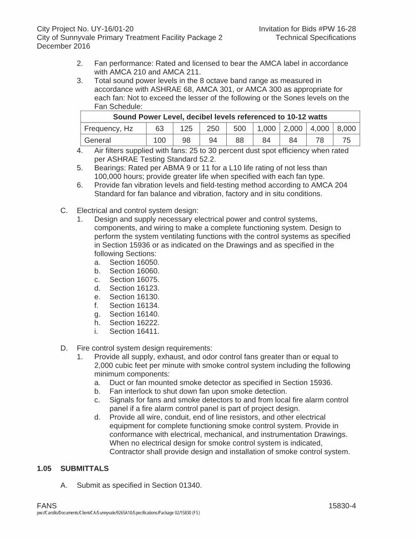
City Project No. UY-16/01-20 Invitation for Bids #PW 16-28City of Sunnyvale Primary Treatment Facility Package 2 Technical SpecificationsDecember 2016
FANS 15830-4 pw://Carollo/Documents/Client/CA/Sunnyvale/9265A10/Specifications/Package 02/15830 (FS)
2. Fan performance: Rated and licensed to bear the AMCA label in accordance with AMCA 210 and AMCA 211.
3. Total sound power levels in the 8 octave band range as measured in accordance with ASHRAE 68, AMCA 301, or AMCA 300 as appropriate for each fan: Not to exceed the lesser of the following or the Sones levels on the Fan Schedule:
Sound Power Level, decibel levels referenced to 10-12 wattsFrequency, Hz 63 125 250 500 1,000 2,000 4,000 8,000General 100 98 94 88 84 84 78 75
4. Air filters supplied with fans: 25 to 30 percent dust spot efficiency when rated per ASHRAE Testing Standard 52.2.
5. Bearings: Rated per ABMA 9 or 11 for a L10 life rating of not less than 100,000 hours; provide greater life when specified with each fan type.
6. Provide fan vibration levels and field-testing method according to AMCA 204 Standard for fan balance and vibration, factory and in situ conditions.
C. Electrical and control system design:1. Design and supply necessary electrical power and control systems,
components, and wiring to make a complete functioning system. Design to perform the system ventilating functions with the control systems as specified in Section 15936 or as indicated on the Drawings and as specified in the following Sections:a. Section 16050. b. Section 16060. c. Section 16075. d. Section 16123. e. Section 16130. f. Section 16134. g. Section 16140. h. Section 16222. i. Section 16411.
D. Fire control system design requirements:1. Provide all supply, exhaust, and odor control fans greater than or equal to
2,000 cubic feet per minute with smoke control system including the following minimum components:a. Duct or fan mounted smoke detector as specified in Section 15936. b. Fan interlock to shut down fan upon smoke detection.c. Signals for fans and smoke detectors to and from local fire alarm control
panel if a fire alarm control panel is part of project design.d. Provide all wire, conduit, end of line resistors, and other electrical
equipment for complete functioning smoke control system. Provide in conformance with electrical, mechanical, and instrumentation Drawings. When no electrical design for smoke control system is indicated, Contractor shall provide design and installation of smoke control system.
1.05 SUBMITTALS
A. Submit as specified in Section 01340.
City Project No. UY-16/01-20 Invitation for Bids #PW 16-28City of Sunnyvale Primary Treatment Facility Package 2 Technical SpecificationsDecember 2016
FANS 15830-5 pw://Carollo/Documents/Client/CA/Sunnyvale/9265A10/Specifications/Package 02/15830 (FS)
B. Submit as specified in Section 15050 for equipment anchorage requirement.
C. Product data:1. Materials.2. Primary and ancillary equipment.3. Sound Power Level in each of 8 octave bands and overall Sones.4. Fan system layout, mechanical, electrical power, and control diagrams.5. Supports, vibration isolators, and seismic bracing calculations and details.6. Calculated fan vibration levels and field-testing method.7. Bearing life.8. Fan performance curves showing specified operating condition.
D. Provide vendor operation and maintenance manual as specified in Section 01730. 1. Furnish bound sets of installation, operation, and maintenance instructions for
each type fan.
E. Provide Manufacturer's Certificate of Source Testing as specified in Section 01756.
1.06 QUALITY ASSURANCE
A. Provide fans:1. Listed by UL.2. Rated in accordance with AMCA.
1.07 DELIVERY, STORAGE, AND HANDLING
A. Deliver units in 1 piece, factory assembled, internally wired, and lubricated.
B. Protect equipment from dust and atmospheric exposure as recommended by the unit manufacturer:1. As a minimum provide temporary closures for equipment openings designed
for airflow.
1.08 EXTRA MATERIALS
A. Provide 2 extra sets (3 sets total) of filters per installed fan for fans specified with filters.
B. Provide 1 extra set of belts per installed fan for fans specified with belt drives.
PART 2 PRODUCTS
2.01 TYPE 2, UP-BLAST CENTRIFUGAL ROOF EXHAUSTERS
A. Manufacturers: One of the following or equal:1. Greenheck, Model CUBE.2. Loren Cook, Model ACRU.3. Penn Ventilator, Model Fumex.
City Project No. UY-16/01-20 Invitation for Bids #PW 16-28City of Sunnyvale Primary Treatment Facility Package 2 Technical SpecificationsDecember 2016
FANS 15830-6 pw://Carollo/Documents/Client/CA/Sunnyvale/9265A10/Specifications/Package 02/15830 (FS)
B. Characteristics:1. Roof-mounted, upblast circular exhaust fan unit.2. Backward inclined centrifugal fan wheel with Venturi inlet; performance as
scheduled.3. Materials: Aluminum fan, housing, roof curb, and accessories.4. Fan bearings: Permanently lubricated ball bearing type.5. Belt drive rated for 150 percent of motor horsepower.6. Motor characteristics: As scheduled.7. Finishes: Provide Kynar paint coating over compatible primer on all steel
surfaces.8. Provide roof curb and duct adapter.9. Provide other accessories as scheduled.
C. Accessories:1. Mounting brackets: Necessary for installation.2. Roof curb:
a. Factory fabricated of 16-gauge aluminum with wood nailer strip and gaskets.
b. Capable of supporting entire unit weight.c. Suitable for installing and connecting ductwork to curb.d. In accordance with NRCA Standards.e. Extend a minimum of 8 inches above top of built up roofing or concrete
roofing, but no less than 14 inches high.f. Flashing: In accordance with NRCA Standards.
3. Bird screen: Provide bird screen if no screen is listed on the Fan Schedule.
2.02 TYPE 3, FILTERED CENTRIFUGAL ROOF SUPPLY FANS
A. Manufacturers: One of the following or equal:1. Greenheck, Model RSFP.2. Loren Cook, Model ASP/ASP-T.3. ACME, Model PL.
B. Characteristics:1. Roof-mounted, louvered penthouse hooded supply fan with hinged cover.2. Forward-curved centrifugal fan wheel.3. Materials: Galvanized steel or aluminum as scheduled.4. Fan bearings: Permanently lubricated ball bearing type.5. Belt drive rated for 150 percent of motor horsepower.
C. Accessories: 1. Filter section:
a. Low velocity 2-inch thick pleated, washable filters of commercially available sizes.
b. Filter face velocity: Not to exceed 350 feet per minute nominal flow.c. Provide filters of identical size for any 1 unit.d. Filters: American Air Filter or equal.
2. Insulated cover to prevent condensation.

City Project No. UY-16/01-20 Invitation for Bids #PW 16-28City of Sunnyvale Primary Treatment Facility Package 2 Technical SpecificationsDecember 2016
FANS 15830-7 pw://Carollo/Documents/Client/CA/Sunnyvale/9265A10/Specifications/Package 02/15830 (FS)
3. Finishes: Provide Kynar paint coating over compatible primer on all steel surfaces.
4. Provide roof curb and duct adapter; same material as fan and housing. Extend a minimum of 8 inches above top of built up roofing or concrete roofing/slab, but no less than 14 inches high. Install flashing in accordance with NRCA Standards.
2.03 TYPE 4, SIDEWALL PROPELLER FANS
A. Manufacturers: One of the following or equal:1. Greenheck, Model SC, or SBC.2. Loren Cook, Model AWD or AWB.3. Penn Ventilator, similar model.
B. Type: Wall-mounted, low noise propeller type, packaged unit.1. Fan: Statically and dynamically balanced propeller with aluminum blades,
unless noted otherwise.2. Motor: Permanently lubricated; selected to avoid running in the service factor.
C. Accessories:1. Motor and fan side OSHA guards.2. Wall mount collar when necessary for installation as indicated on the
Drawings. 3. Dampers with damper guards when damper scheduled.4. Weather hood when scheduled.5. Bird screen: Provide bird screen if no screen is listed on the Fan Schedule.6. Finish: Coat fan, housing, and accessories with polyester finish.7. Diffusers and louvers when scheduled.8. Mounting hardware.
2.04 TYPE 5, FRP SIDEWALL PROPELLER FANS
A. Manufacturers: One of the following or equal:1. Hartzell Fans, Series 59.
B. Type: Wall-mounted, low noise propeller type, packaged unit:1. Fan: One piece molded fiberglass fan housing with solid fiberglass motor
support base. Fan housing includes venturi orifice to increase efficiency and seal propeller tips. Statically and dynamically balanced propeller with FRP blades and Housing.
2. Highly efficient, one-piece, solid fiberglass airfoil type propeller, statically and dynamically balanced.
3. Motor: Permanently lubricated; selected to avoid running in the service factor.Mounting base is fabricated of solid fiberglass, designed to maximize strength and minimize restrictions to air flow.
4. Hardware: 316 stainless steel.
C. Accessories:1. Motor and fan side 304 stainless steel OSHA guards.
City Project No. UY-16/01-20 Invitation for Bids #PW 16-28City of Sunnyvale Primary Treatment Facility Package 2 Technical SpecificationsDecember 2016
FANS 15830-8 pw://Carollo/Documents/Client/CA/Sunnyvale/9265A10/Specifications/Package 02/15830 (FS)
2. Wall mount collar when necessary for installation as indicated on the Drawings.
3. Dampers with damper guards when damper scheduled.4. Mounting Flange. 5. Bird screen: Provide bird screen if no screen is listed on the Fan Schedule.6. Finish: Coat fan, housing, and accessories with corrosion resistant finish to
H2S and mist applications.
2.05 TYPE 11, TUBULAR CENTRIFUGAL FANS
A. Manufacturers: One of the following or equal:1. Greenheck, Model TCF.2. Loren Cook, Centri-Vane type CVD or CVB.3. Penn Ventilator, Centrex, Model REX.
B. Characteristics:1. Type: In-line tubular centrifugal fan with straightening vanes in a unit housing.2. Fan: Airfoil, non-overloading centrifugal aluminum fan on aluminum hub.3. Housing: Tubular aluminum construction with airflow straightening vanes;
provide flanged inlet and outlet to match adjacent ducting.4. Motor: Permanently lubricated bearings rated for L10 life of 200,000 hours;
mounted on vibration isolators; type as scheduled.
C. Accessories:1. Provide NEMA Type 3R disconnect outside housing, unless otherwise
scheduled. 2. Provide belt guard and adjustable belt sheaves when belt drive scheduled.3. Provide lifting lugs.4. Finish: Kynar protective coating.
2.06 TYPE 12, FRP BASE MOUNT CENTRIFUGAL FANS
A. Manufacturers: One of the following or equal:1. New York Blower Company.2. Hartzell Fan.
B. Characteristics:1. Fan design/construction: In accordance with ASTM D 4167.2. Fan housing: Solid fiberglass reinforced plastic (FRP).3. Fan wheel: Backward curved or backward inclined airfoil blades,
non-overloading throughout entire curve at rated speed; solid FRP, totally encapsulated aluminum core insert for secure attachment to shaft.
4. Shaft: Ground and polished ASTM A 108 grade 1040/1045 steel with Hastelloy sleeve in air stream or Type 316 stainless steel. Shaft to have maximum 1-mil run-out.
5. Bearings: Minimum ABMA L-10 life rating of 100,000 hours, grease lubricated with lube tubes extended to outside of housing.
6. Shaft seal: Type 316 stainless steel double lip rings and springs. Extend shaft seal 1/2 inch beyond seal where required.
7. Duct connections: Provide flanged connections.
City Project No. UY-16/01-20 Invitation for Bids #PW 16-28City of Sunnyvale Primary Treatment Facility Package 2 Technical SpecificationsDecember 2016
FANS 15830-9 pw://Carollo/Documents/Client/CA/Sunnyvale/9265A10/Specifications/Package 02/15830 (FS)
8. Drain: Provide 1-inch diameter FRP pipe bonded to a low point in the housing; provide PVC ball valve and threaded plug.
9. Fan inspection port: Provide 8-inch diameter fan housing port to allow examination of interior.
10. Motor and belt cover/guard: Provide FRP, aluminum, or Type 316 stainless steel cover over motor and belt drive with louvered side panels to allow motor ventilation sufficient to prevent overheating at 100 percent of full load.
11. Electrical grounding: Coat air stream surfaces with graphite impregnated resin with grounding straps to motor frames or fan base to control static electricity.
12. Abrasive moisture coating: Coat fan wheel with 50 to 60 mil abrasive/erosive resistant coating.
13. Base and bearing support structures: Rigid Structural FRP, aluminum, or Type 316 stainless steel.
14. Duct connection orientation: As indicated on the Drawings. For fans at the Odor Control Facility, coordinate with the scrubber manufacturer.
15. Drive:a. Belt or direct as scheduled.b. Provide fixed pitch for fans less than 5-hp motors. For fans with larger
than 5-hp motors provide multiple sheaves. Belts shall be banded and matched or individual belts as selected by fan Manufacturer. Belt drive system shall be selected by the fan Manufacturer based on the fan Manufacturer's fan design requirements to allow fan to meet vibration performance requirements in this Section and Section 15958.
16. FRP requirements:a. Suitable for continuous operation when exposed to vapors and gases
expected to include methane, hydrogen sulfide, chlorine gas, sulfur dioxide, gasoline vapors, ammonia, and water saturated air. Air stream may contain droplets of dilute sulfuric acid, greases, and particulate matter and may vary from 30 degrees F to 130 degrees F.
b. Housing resin:1) Type: Premium polyester resin. 2) Resin shall achieve Class I flame spread rating below 25 when
tested in accordance with ASTM E 84 without the use of additives.3) Manufacturer: One of the following or equal:
a) Ashland Chemical Company.b) Derakane or Hetron.
c. Wheel resin:1) Type: Premium Vinyl ester resin.2) Resin shall achieve Class II flame spread rating below 30 when
tested in accordance with ASTM E 84.3) Manufacturer: One of the following or equal:
a) Dow Chemical Company.b) Derakane 510A40 or 570A40; Ashland Chemical Company.
d. Protect fiberglass surfaces with minimum 10-mil thickness of ultraviolet resistant resin after initial visual inspections of housing exterior is complete.
e. Provide Veil-Nexus corrosion resistant surfacing veil and additional coat of fiberglass reinforced plastic resin on surfaces exposed to the air stream for corrosion resistance and chopped strand fiberglass for structural core strength.
City Project No. UY-16/01-20 Invitation for Bids #PW 16-28City of Sunnyvale Primary Treatment Facility Package 2 Technical SpecificationsDecember 2016
FANS 15830-10pw://Carollo/Documents/Client/CA/Sunnyvale/9265A10/Specifications/Package 02/15830 (FS)
17. Balancing: Factory balance the fan wheel to G2.5 per AMCA 204 and the final fan/motor assembly to BV-4 per AMCA 204 and provide certified reports for approval prior to shipment.
18. Fan Arrangement 1 for fan larger than 5-hp motor and other arrangement acceptable to the ENGINEER per AMCA Standards to be installed as shown on the Drawings and recommended by fan manufacturer to provide a rigid installation not exceeding the vibration limits as specified in Section 15958 when operating over the entire range of the speed. It is the responsibility of the fan manufacturer to provide the best available arrangement that meets the design intent of the Specifications.
19. Other accessories:a. Fan Mounting: Provide fans that are designed to be installed in a rigid
mount or flexible mount with vibration spring isolators. The fan Manufacturer shall select one of these two fan-mounting methods and design the fan and all fan system components for the selected mounting method to meet the vibration criteria in this Section and Section 15958, whichever more stringent shall apply:1) If a flexible mount configuration is selected by the fan manufacturer,
provide guided vibration isolator for fans, so that not more than 10 percent of the vibration amplitude of the fan and motor is transmitted to the supporting structure.
2) Fan manufacturer and Contractor shall coordinate the fan'sequipment pad dimensions and requirements with the fan mounting method (rigid or flexible) selected by the fan manufacturer and anchorage by the Contractor.
b. Cover access doors: FRP, neoprene gasket, non-hinged, stainless steel bolts.
c. Fasteners: Type 316 stainless steel and shall be encapsulated in FRP when exposed to air stream.
d. Inlet box:1) Provide FRP inlet box specifically designed by the fan manufacturer
to optimize fan inlet conditions.2) Maximum pressure loss through inlet box shall be 1.0-inch water
column at specified design flow rate.3) Inlet box shall be mounted and supported from integral
fan/motor/inlet box base with rigid structural FRP, aluminum, or Type 316 stainless steel supports.
4) Inlet box shall have a 1-inch drain connection at the lowest point in the orientation indicated on the Drawings; provide PVC ball valve and threaded plug.
2.07 TYPE 16, MIXED FLOW INDUCED DILUTION EXHAUST FANS
A. Manufacturers: 1. Strobic Air Corporation, Tri-Stack models.2. Characteristics:3. Type: Laboratory fume hood exhaust fan and discharge stack assembly.4. Fan: Mixed flow, axial/backward centrifugal fan blades with stationary
discharge guide vane section providing non-stall, non-overloading performance.
City Project No. UY-16/01-20 Invitation for Bids #PW 16-28City of Sunnyvale Primary Treatment Facility Package 2 Technical SpecificationsDecember 2016
FANS 15830-11pw://Carollo/Documents/Client/CA/Sunnyvale/9265A10/Specifications/Package 02/15830 (FS)
5. Motor: Direct drive TEFC, mill and chemical duty motor with 1.15 service factor and 150,000 hour L-50 bearing life.
6. Housing: Weatherproof design provided with internal drain to prevent rainwater from entering ducting.
7. Exhaust stack: Vertical exhaust stack features:a. Twin FRP discharge nozzle with passive third central stack to produce
high velocity with minimal pressure drop and create Venturi effect to aspirate additional air. The FRP shall be chemically and UV resistant.
b. Entrainment windbands shall provide induction of secondary air up to 270 percent of the primary airflow to achieve exhaust plume velocities up to 6,000 feet per minute. Induction shall take place downstream of the fan impeller and shall not influence BHP or static pressure requirements.
c. Rigidly supported needing no guy wires for support.8. Minimum AMCA "C" spark-resistant construction.9. Bolted access door provided for impeller inspection.10. Fan dynamic balance shall not exceed 0.5-mil, peak-to-peak for nominal
900-rpm, 1,200-rpm, and 1,800-rpm fans, or 0.055 in/sec peak for 1,800-rpm, 0.035 in/sec peak for 1,200-rpm, and 0.030 in/sec peak for 900-rpm fans measured at the blade pass area when operating at fan frequency. Vibration isolation shall be limited to rubber-in-shear pad type isolators unless otherwise specified.a. Factory test reports detailing vibration levels at the blade pass area shall
be submitted. Vibration levels shall be reported in both the axial and radial direction.
11. PTFE gaskets between modular sections: Type 316 stainless steel or Monel fasteners.
12. Finishes: Vinyl ester coating suitable for wastewater treatment plant applications.All steel and aluminum surfaces components within the airstream that are not stainless steel or fiberglass must be surface prepped by abrasive blast clean to SSPC-SP10. Chemically cleaning of these components as a form of surface preparation is not acceptable. These components must be coated with a high solids epoxy with low VOC chemical resistant barrier coating epoxy. The coating system, a total thickness of up to 12 mils, is not affected by the UV component of sunlight (does not chalk), and has superior corrosion resistance to acid, alkali, and solvents. Coating system shall exceed 7,000-hour ASTM B117 Salt Spray Resistance. Standard finish color to be gray. All coatings that include a zinc rich epoxy primer are strictly prohibited.
13. Warranty: Fan manufacturer shall provide a 7-year parts warranty from time of startup acceptance by Owner to include fan, plenum, motor and drive mechanisms including pillow blocks, sheaves, shafts, couplings and belts. This warranty shall be held solely by fan manufacturer. It is unacceptable to extend the warranty of a provided component supplier (i.e., motors, dampers, actuators). All warranty claims shall be the sole responsibility of the fan manufacturer.
B. Accessories:1. Inlet mixing plenum: Provide inlet mixing plenum as indicated on the Drawings.
a. Mixing plenum shall be single-walled and capable of supporting the fan assembly above it, including all specified accessories, without needing guy wires for support.

City Project No. UY-16/01-20 Invitation for Bids #PW 16-28City of Sunnyvale Primary Treatment Facility Package 2 Technical SpecificationsDecember 2016
FANS 15830-12pw://Carollo/Documents/Client/CA/Sunnyvale/9265A10/Specifications/Package 02/15830 (FS)
b. Mixing plenum shall be capable of withstanding a minimum of 12-inch w.g. negative pressure.
c. The primary air inlets shall be located on the bottom or side as noted on Contract Drawings. 1) Provide vortex breakers on all side inlets to the fan mixing plenum.
d. Unless otherwise specified or indicated on the Drawings, the mixing plenum shall be suitable for mounting on roof and concrete curbs.
e. Bypass dampers: Provide opposed blade low-leakage airfoil control dampers with extended shaft for connection to an operator.1) Bypass dampers shall be of aluminum construction.2) Provide rain hoods with each damper.3) Provide hand quadrant operator for manual control of each bypass
damper.f. Provide a minimum on 1 access door for access to interior of the plenum.
2. Provide disconnect switch rated as scheduled or indicated in Division 16.3. Provide safety screen over inlet of fan.4. Provide NRCA-approved roof curb and flashing or other fan base as detailed
on the Drawings to support the fan and plenum.
C. Additional Testing References:1. Fans shall have been tested under AMCA 210-85, "Laboratory Methods of
Testing Fans for Rating." Tests shall have been witnessed by an independent agency.
2. Documented aspiration tests shall have been performed in conjunction with the fan performance test.a. Fans shall have been tested under AMCA 260-07, "Laboratory Methods of
Testing Induced Flow Fans for Rating," or alternatively; test shall incorporate AMCA 210 testing standards and physically measure the air volume entering and exiting the fan.
b. Tests shall have been witnessed by an independent agency.3. Sound testing shall be in accordance with AMCA 300.4. Fans shall be UL and CUL listed per UL 705 safety standard.5. Fans shall meet the criteria of NFPA-45.
2.08 SOURCE QUALITY CONTROL
A. Factory test fans listed on the Fan Schedule for proper operation, performance, and electrical controls.
PART 3 EXECUTION
3.01 EXAMINATION
A. Examine and verify that Work is in condition to receive installation specified in this Section.
B. Take measurements and verify dimensions to ascertain fit of installation.
C. Ascertain support and openings are correctly located.

City Project No. UY-16/01-20 Invitation for Bids #PW 16-28City of Sunnyvale Primary Treatment Facility Package 2 Technical SpecificationsDecember 2016
FANS 15830-13pw://Carollo/Documents/Client/CA/Sunnyvale/9265A10/Specifications/Package 02/15830 (FS)
3.02 PREPARATION
A. Before installation, remove dust and debris from equipment and ducts.
B. During installation and until equipment is operated, protect equipment and ducts from dust and debris by covering openings with tape or plastic.
3.03 INSTALLATION
A. Observe applicable installation requirements as specified in Section 15050.
B. Anchoring and support:1. Provide anchoring and support for fans and appurtenances.2. Provide anchoring to sustain seismic and wind forces as specified in
Sections 01612 and 01614.
C. Adjust alignment of ducts where necessary to resolve conflicts with architectural features or to resolve conflicts with the work of other trades.
D. Install and wire unit fans and controls in accordance with manufacturer'srecommendations.
E. Install flexible connections to fans.
F. Install roof curb and fan as recommended by fan manufacturer.
G. For fan housings with threaded water trap drain, provide drain piped from fan housing to the nearest drain channel, floor drain, or sump.
3.04 FIELD QUALITY CONTROL
A. Test equipment and installation to verify tightness, operation, and unit vibration is within manufacturer's submitted maximum.
B. Test equipment performance and balance equipment as specified in Section 15954.
3.05 COMMISSIONING AND PROCESS START-UP REQUIREMENTS
A. As specified in Section 01756 and this Section.
B. Manufacturer(each) services for each type of fan:1. Provide Manufacturer's Certificate of Source Testing:2. Manufacturer's Representative onsite requirements:
a. Installation: 1 trip, 2 days minimum each. b. Functional Testing: 1 trip, 1 day minimum each.
3. Training:a. Maintenance: 4 hours per session, 2 sessions. b. Operation: 4 hours per session, 2 sessions.
4. Process operational period:a. As required by Owner or Contractor.

City Project No. UY-16/01-20 Invitation for Bids #PW 16-28City of Sunnyvale Primary Treatment Facility Package 2 Technical SpecificationsDecember 2016
FANS 15830-14pw://Carollo/Documents/Client/CA/Sunnyvale/9265A10/Specifications/Package 02/15830 (FS)
3.06 SCHEDULES
A. Fan Schedule:

FANS 15830-15pw://Carollo/Documents/Client/CA/Sunnyvale/9265A10/Specifications/Package 02/15830 (FS)
City Project No. UY-16/01-20 Invitation for Bids #PW 16-28City of Sunnyvale Primary Treatment Facility Package 2 Technical SpecificationsDecember 2016
Equi
p.
Tag
Equi
p.
Nam
eLo
catio
n
Fan
Moto
rAd
ditio
nal
Requ
irem
ents
(S
ee lis
ted
Note
s)Ty
peDr
iveMi
n.
CFM
Min.
ES
P"
Max.
RPM
Fan
Diam
.No
ise
Sone
shp
V/
Ph.
Max.
rpm
FAN-
212.9
11,
FAN-
212.9
12
Head
works
Fou
l Air
Boos
ter F
an N
o. 1,
No. 2
Grit a
nd S
creen
ings
Hand
ling F
acilit
y 12
Be
lt 9,3
50
2.5
1,570
24
80
dba @
5 f
t 10
46
0/3
1,800
8
FAN-
212.9
01,
FAN-
212.9
02
Load
ing R
oom
Supp
ly Fa
n No.
1, No
. 2
Grit a
nd S
creen
ings
Hand
ling F
acilit
y 5
Dire
ct 2,9
00
0.5
1,160
28
75
dba @
5 f
t 1
460/3
1,1
00
8
FAN-
212.9
03,
FAN-
212.9
04
Grit W
ashe
r Roo
m Su
pply
Fan N
o. 1,
No. 2
Grit a
nd S
creen
ings
Hand
ling F
acilit
y 5
Dire
ct 3,6
50
0.5
1,160
28
75
dba @
5 f
t 1
460/3
1,1
00
8,23
FAN-
212.9
13,
FAN-
212.9
14
Grit W
ashe
r Roo
m Ex
haus
t Fan
No.
1, No
. 2
Grit a
nd S
creen
ings
Hand
ling F
acilit
y 2
Belt
4,000
1
1,050
Pe
r Mfr
17 S
ones
2
460/3
1,8
00
1,5,8
FAN-
221.9
01,
FAN-
221.9
02
Pump
Roo
m Su
pply
Fan N
o. 1,
No. 2
Inf
luent
Pump
St
ation
3
Belt
5,000
0.6
5 60
0 Pe
r Mfr
17 S
ones
3
460/3
1,8
00
1,5,8
FAN-
221-
911,
FAN-
221-
912
Pump
Roo
m Ex
haus
t Fa
n No.
1, No
. 2
Influe
nt Pu
mp
Stati
on
2 Be
lt 5,5
00
1 1,2
00
Per M
fr 20
Son
es
3 46
0/3
1,800
1,5
,8
FAN-
221.9
03,
FAN-
221-
904
Stair
well S
upply
Fan
No
. 1, N
o. 2
Influe
nt Pu
mp
Stati
on
4 Di
rect
1,000
0.5
1,7
50
Per M
fr 9 S
ones
1/3
46
0/3
1,800
1,8
FAN-
221.9
13,
FAN-
221-
914
Stair
well E
xhau
st Fa
n No.
1, No
. 2
Influe
nt Pu
mp
Stati
on
2 Be
lt 1,0
00
0.5
1,400
Pe
r Mfr
10 S
ones
1/3
46
0/3
1,800
1,5
,8
FAN-
231.9
11,
FAN-
231.9
12
Grit B
asins
Fou
l Air
Boos
ter F
an N
o. 1,
No. 2
Grit B
asins
12
Be
lt 2,0
00
1.5
2,164
15
80
dba @
5 f
t 2
460/3
1,8
00
8
FAN-
251.2
11,
FAN-
251.2
12,
FAN-
251.2
13
Odor
Con
trol F
an
No. 1
, No.
2, No
. 3
Odor
Con
trol
Facil
ity
12
Belt
12,07
3 7.5
1,4
25
30
80 db
a @
5 ft
30
460/3
1,8
00
8, 25
FAN-
241.9
01,
FAN-
241.9
02
Prim
ary
Sedim
entat
ion T
ank
Galle
ry Su
pply
Fan
No. 1
, No.
2
PSTs
11
Be
lt 4,7
60
1 1,6
70
18
93 db
a @
5 ft
3 46
0/3
1,800
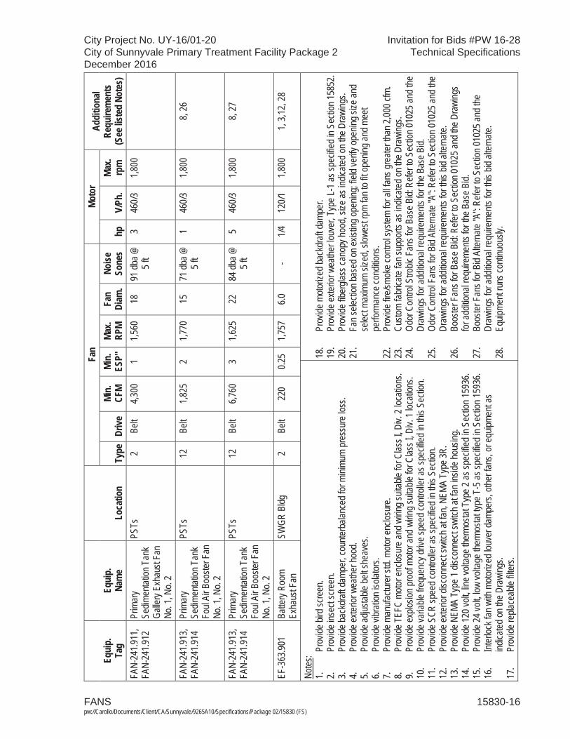
FANS 15830-16pw://Carollo/Documents/Client/CA/Sunnyvale/9265A10/Specifications/Package 02/15830 (FS)
City Project No. UY-16/01-20 Invitation for Bids #PW 16-28City of Sunnyvale Primary Treatment Facility Package 2 Technical SpecificationsDecember 2016
Equi
p.
Tag
Equi
p.
Nam
eLo
catio
n
Fan
Moto
rAd
ditio
nal
Requ
irem
ents
(S
ee lis
ted
Note
s)Ty
peDr
iveMi
n.
CFM
Min.
ES
P"
Max.
RPM
Fan
Diam
.No
ise
Sone
shp
V/
Ph.
Max.
rpm
FAN-
241.9
11,
FAN-
241.9
12
Prim
ary
Sedim
entat
ion T
ank
Galle
ry Ex
haus
t Fan
No
. 1, N
o. 2
PSTs
2
Belt
4,300
1
1,560
18
91
dba @
5 f
t 3
460/3
1,8
00
FAN-
241.9
13,
FAN-
241.9
14
Prim
ary
Sedim
entat
ion T
ank
Foul
Air B
ooste
r Fan
No
. 1, N
o. 2
PSTs
12
Be
lt 1,8
25
2 1,7
70
15
71 db
a @
5 ft
1 46
0/3
1,800
8,
26
FAN-
241.9
13,
FAN-
241.9
14
Prim
ary
Sedim
entat
ion T
ank
Foul
Air B
ooste
r Fan
No
. 1, N
o. 2
PSTs
12
Be
lt 6,7
60
3 1,6
25
22
84 db
a @
5 ft
5 46
0/3
1,800
8,
27
EF-3
63.90
1 Ba
ttery
Room
Ex
haus
t Fan
SW
GR B
ldg
2 Be
lt 22
0 0.2
5 1,7
57
6.0
- 1/4
12
0/1
1,800
1,
3,12,
28
Notes
: 1.
Prov
ide bi
rd sc
reen
. 2.
Prov
ide in
sect
scre
en.
3.Pr
ovide
back
draft
damp
er, c
ounte
rbala
nced
for m
inimu
m pr
essu
re lo
ss.
4.Pr
ovide
exter
ior w
eathe
r hoo
d. 5.
Prov
ide ad
justab
le be
lt she
aves
. 6.
Prov
ide vi
brati
on is
olator
s. 7.
Prov
ide m
anufa
cture
r std.
moto
r enc
losur
e. 8.
Prov
ide T
EFC
motor
enclo
sure
and w
iring s
uitab
le for
Clas
s I, D
iv. 2
locati
ons.
9.Pr
ovide
explo
sion p
roof
motor
and w
iring s
uitab
le for
Clas
s I, D
iv. 1
locati
ons.
10.
Prov
ide va
riable
freq
uenc
y driv
e spe
ed co
ntroll
er as
spec
ified i
n this
Sec
tion.
11.
Prov
ide S
CR sp
eed c
ontro
ller a
s spe
cified
in th
is Se
ction
. 12
.Pr
ovide
exter
ior di
scon
nect
switc
h at fa
n, NE
MA T
ype 3
R.
13.
Prov
ide N
EMA
Type
1 dis
conn
ect s
witch
at fa
n ins
ide ho
using
. 14
.Pr
ovide
120 v
olt, li
ne vo
ltage
ther
mosta
t Typ
e 2 as
spec
ified i
n Sec
tion 1
5936
. 15
.Pr
ovide
24 vo
lt, low
volta
ge th
ermo
stat ty
pe T
-5 as
spec
ified i
n Sec
tion 1
5936
. 16
.Int
erloc
k fan
with
moto
rized
louv
er da
mper
s, oth
er fa
ns, o
r equ
ipmen
t as
indica
ted on
the D
rawi
ngs.
17.
Prov
ide re
place
able
filter
s.
18.
Prov
ide m
otoriz
ed ba
ckdr
aft da
mper
. 19
.Pr
ovide
exter
ior w
eathe
r louv
er, T
ype L
-1 as
spec
ified i
n Sec
tion 1
5852
. 20
.Pr
ovide
fiber
glass
cano
py ho
od, s
ize as
indic
ated o
n the
Dra
wing
s. 21
.Fa
n sele
ction
base
d on e
xistin
g ope
ning;
field
verify
open
ing si
ze an
d se
lect m
axim
um si
zed,
slowe
st rp
m fan
to fit
open
ing an
d mee
t pe
rform
ance
cond
itions
. 22
.Pr
ovide
fire/s
moke
contr
ol sy
stem
for al
l fans
grea
ter th
an 2,
000 c
fm.
23.
Custo
m fab
ricate
fan s
uppo
rts as
indic
ated o
n the
Dra
wing
s.
24.
Odor
Con
trol S
trobic
Fan
s for
Bas
e Bid:
Refe
r to S
ectio
n 010
25 an
d the
Dr
awing
s for
addit
ional
requ
ireme
nts fo
r the
Bas
e Bid.
25
.Od
or C
ontro
l Fan
s for
Bid
Alter
nate
"A":
Refer
to S
ectio
n 010
25 an
d the
Dr
awing
s for
addit
ional
requ
ireme
nts fo
r this
bid a
ltern
ate.
26.
Boos
ter F
ans f
or B
ase B
id: R
efer t
o Sec
tion 0
1025
and t
he D
rawi
ngs
for ad
dition
al re
quire
ments
for t
he B
ase B
id.
27.
Boos
ter F
ans f
or B
id Al
terna
te "A
": Re
fer to
Sec
tion 0
1025
and t
he
Draw
ings f
or ad
dition
al re
quire
ments
for t
his bi
d alte
rnate
. 28
.Eq
uipme
nt ru
ns co
ntinu
ously
.
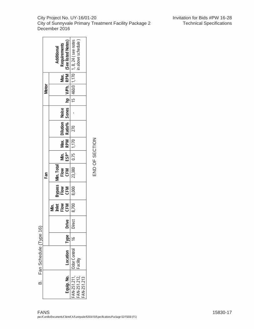
FANS 15830-17pw://Carollo/Documents/Client/CA/Sunnyvale/9265A10/Specifications/Package 02/15830 (FS)
City Project No. UY-16/01-20 Invitation for Bids #PW 16-28City of Sunnyvale Primary Treatment Facility Package 2 Technical SpecificationsDecember 2016
B.
Fan
Sch
edul
e (T
ype
16)
Equi
p. N
o.Lo
catio
n
Fan
Moto
r
Addi
tiona
l Re
quire
men
ts(S
ee lis
ted
Note
s)Ty
peDr
ive
Min.
In
let
Flow
CF
M
Bypa
ss
Flow
CF
M
Min.
Tot
al Fl
ow
CFM
Min.
ES
P"Ma
x. RP
MDi
lutio
n Ra
tio%
Noise
So
nes
hpV/
Ph.
Max.
RPM
FAN-
251.2
11,
FAN-
251.2
12,
FAN-
251.2
13
Odor
Con
trol
Facil
ity
16
Dire
ct 8,7
00
8,000
23
,380
0.75
1,170
27
0 -
15
460/3
1,17
0 1,
8, 24
( se
e note
s in
abov
e sch
edule
)
EN
D O
F S
EC
TIO
N

City Project No. UY-16/01-20 Invitation for Bids #PW 16-28City of Sunnyvale Primary Treatment Facility Package 2 Technical SpecificationsDecember 2016
LOUVERS 15852-1 pw://Carollo/Documents/Client/CA/Sunnyvale/9265A10/Specifications/Package 02/15852 (FS)
SECTION 15852
LOUVERS
PART 1 GENERAL
1.01 SUMMARY
A. Section includes:1. Stationary weather louvers.2. Manually operated adjustable louvers.3. Fiberglass reinforced plastic stationary louvers.4. Fiberglass reinforced plastic adjustable louvers.
B. Related sections:1. The Contract Documents are complementary; what is called for by one is as
binding as if called for by all.2. It is the Contractor's responsibility for scheduling and coordinating the Work of
subcontractors, suppliers, and other individuals or entities performing or furnishing any of Contractor's Work.
3. The following Sections are related to the Work described in this Section. This list of Related Sections is provided for convenience only and is not intended to excuse or otherwise diminish the duty of the Contractor to see that the completed Work complies accurately with the Contract Documents:a. Section 15954 - Testing, Adjusting, and Balancing for HVAC.
1.02 REFERENCES
A. Air Movement and Control Association International, Inc. (AMCA): 1. 500-L - Laboratory Methods of Testing Louvers for Rating.2. 500-D - Laboratory Methods of Testing Dampers for Rating.3. 511 - Certified Ratings Program - Product Rating Manual for Air Control
Devices.
B. ASTM International (ASTM):1. D 2584 - Standard Test Method for Ignition Loss of Cured Reinforced Resins.
C. Underwriters Laboratories, Inc. (UL).
1.03 PERFORMANCE REQUIREMENTS
A. Performance: In accordance with AMCA 511 when tested in accordance with AMCA 500.
B. Designed for 20 pounds per square foot wind load.

City Project No. UY-16/01-20 Invitation for Bids #PW 16-28City of Sunnyvale Primary Treatment Facility Package 2 Technical SpecificationsDecember 2016
LOUVERS 15852-2 pw://Carollo/Documents/Client/CA/Sunnyvale/9265A10/Specifications/Package 02/15852 (FS)
1.04 SUBMITTALS
A. Shop drawings: Include dimensions, anchorage details, and relationships to adjacent materials.
B. Product data.
1.05 QUALITY ASSURANCE
A. Provide louvers with the following, unless otherwise specified:1. AMCA certification and rating in accordance with AMCA 511 for air
performance and water penetration.
PART 2 PRODUCTS
2.01 GENERAL
A. Louver types: Louvers are marked on the drawings with a letter L followed by a number referring to a louver type in this Section. Individual louver size and airflow rates are as indicated on the Drawings.
B. Accessories:1. Provide installation clips and flanged or jamb-mounting styles suitable for the
mounting locations as indicated on the Drawings. 2. Provide extended sills for louvers indicated as installed recessed from the
exterior wall surface.3. Provide stainless steel fasteners unless noted otherwise.4. Corrosion protection.5. Provide gravity damper for all outside air intake and exhaust louvers unless
noted otherwise.
C. Protective coatings for aluminum in contact with concrete or masonry:1. Manufacturers: One of the following or equal.2. Koppers Company, Inc.3. Tarmastic 100.4. Porter Coatings.
2.02 STATIONARY WEATHER LOUVERS, TYPE L-1
A. Manufacturers: One of the following or equal:1. Ruskin, Model ELF 6375DXH.2. Airolite Company, equivalent product.3. American Warming and Ventilating, Inc., equivalent product.
B. Requirements:1. Type: Stationary louver with drainable blades.2. Frame: 6-inch deep, minimum 0.125-inch thick, Type 6063-T5 aluminum with
downspouts and caulking channel provided.
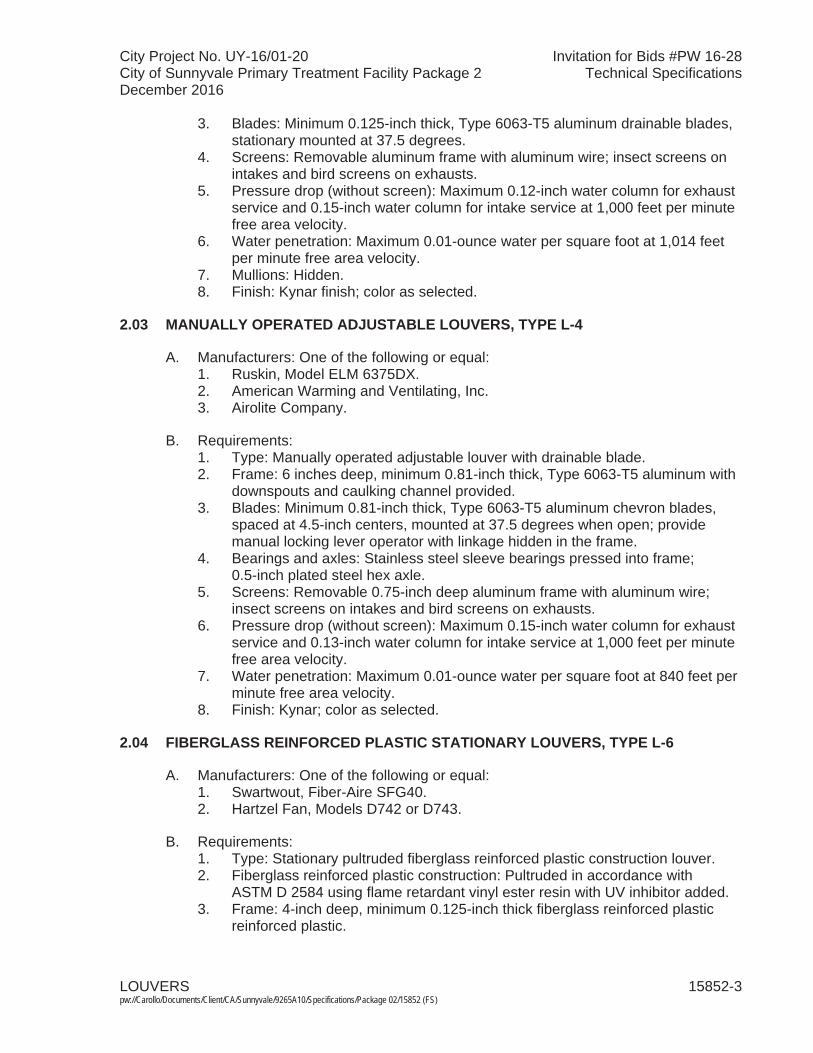
City Project No. UY-16/01-20 Invitation for Bids #PW 16-28City of Sunnyvale Primary Treatment Facility Package 2 Technical SpecificationsDecember 2016
LOUVERS 15852-3 pw://Carollo/Documents/Client/CA/Sunnyvale/9265A10/Specifications/Package 02/15852 (FS)
3. Blades: Minimum 0.125-inch thick, Type 6063-T5 aluminum drainable blades, stationary mounted at 37.5 degrees.
4. Screens: Removable aluminum frame with aluminum wire; insect screens on intakes and bird screens on exhausts.
5. Pressure drop (without screen): Maximum 0.12-inch water column for exhaust service and 0.15-inch water column for intake service at 1,000 feet per minute free area velocity.
6. Water penetration: Maximum 0.01-ounce water per square foot at 1,014 feet per minute free area velocity.
7. Mullions: Hidden.8. Finish: Kynar finish; color as selected.
2.03 MANUALLY OPERATED ADJUSTABLE LOUVERS, TYPE L-4
A. Manufacturers: One of the following or equal:1. Ruskin, Model ELM 6375DX.2. American Warming and Ventilating, Inc.3. Airolite Company.
B. Requirements:1. Type: Manually operated adjustable louver with drainable blade.2. Frame: 6 inches deep, minimum 0.81-inch thick, Type 6063-T5 aluminum with
downspouts and caulking channel provided.3. Blades: Minimum 0.81-inch thick, Type 6063-T5 aluminum chevron blades,
spaced at 4.5-inch centers, mounted at 37.5 degrees when open; provide manual locking lever operator with linkage hidden in the frame.
4. Bearings and axles: Stainless steel sleeve bearings pressed into frame; 0.5-inch plated steel hex axle.
5. Screens: Removable 0.75-inch deep aluminum frame with aluminum wire; insect screens on intakes and bird screens on exhausts.
6. Pressure drop (without screen): Maximum 0.15-inch water column for exhaust service and 0.13-inch water column for intake service at 1,000 feet per minute free area velocity.
7. Water penetration: Maximum 0.01-ounce water per square foot at 840 feet per minute free area velocity.
8. Finish: Kynar; color as selected.
2.04 FIBERGLASS REINFORCED PLASTIC STATIONARY LOUVERS, TYPE L-6
A. Manufacturers: One of the following or equal:1. Swartwout, Fiber-Aire SFG40.2. Hartzel Fan, Models D742 or D743.
B. Requirements:1. Type: Stationary pultruded fiberglass reinforced plastic construction louver.2. Fiberglass reinforced plastic construction: Pultruded in accordance with
ASTM D 2584 using flame retardant vinyl ester resin with UV inhibitor added.3. Frame: 4-inch deep, minimum 0.125-inch thick fiberglass reinforced plastic
reinforced plastic.
City Project No. UY-16/01-20 Invitation for Bids #PW 16-28City of Sunnyvale Primary Treatment Facility Package 2 Technical SpecificationsDecember 2016
LOUVERS 15852-4 pw://Carollo/Documents/Client/CA/Sunnyvale/9265A10/Specifications/Package 02/15852 (FS)
4. Blades: Minimum 0.125-inch thick fiberglass reinforced plastic, spaced at 4-inch centers, mounted at 45 degrees, and drainable K style design.
5. Fasteners: Monel or completely encapsulated in fiberglass reinforced plastic.6. Screens: Removable; fiberglass reinforced plastic insect screens on intakes
and polyvinyl chloride coated wire bird screens on exhausts.7. Pressure drop (without screen): Maximum 0.12 inches water column for intake
service and 0.13 inches water column for exhaust service at 1,000 feet per minute free area velocity.
8. Water penetration: Maximum 0.01-ounce water per square foot at 780 feet per minute free area velocity.
9. Finish: Exterior painted finish; color as selected.
2.05 FIBERGLASS REINFORCED PLASTIC ADJUSTABLE LOUVERS, TYPE L-7.
A. Manufacturers: One of the following or equal:1. Swartwout, Fiber-Aire AFG40.2. Hartzel Fan, Models D744 or D745.
B. Requirements:1. Type: Adjustable pultruded fiberglass reinforced plastic construction louver.2. Fiberglass reinforced plastic construction: Pultruded in accordance with
ASTM D 2584 using flame retardant vinyl ester resin with UV inhibitor added.3. Frame: 4 inches deep, minimum 0.125-inch thick fiberglass reinforced plastic;
provide jamb seals.4. Blades: Minimum 0.125-inch thick fiberglass reinforced plastic, spaced at
5-inch centers, mounted at 45 degrees when open, drainable K style design.5. Bearings and axles: PTFE bearings; 0.75-inch fiberglass reinforced plastic rod
axle.6. Actuator: Fiberglass reinforced plastic face linkage with locking quadrant for
lever actuator.7. Fasteners: Monel or completely encapsulated in fiberglass reinforced plastic.8. Screens: Removable; fiberglass reinforced plastic insect screens on intakes
and polyvinyl chloride coated wire bird screens on exhausts.9. Pressure drop (without screen): Maximum 0.11-inch water column for intake
service and 0.10-inch water column for exhaust service at 1,000 feet per minute free area velocity.
10. Finish: Exterior painted finish; color as selected.
PART 3 EXECUTION
3.01 INSTALLATION
A. Install louvers in accordance with manufacturer's instructions; caulk all frames to make weather tight.
B. Install louvers for machinery, engines, and similar equipment to allow easy louver removal for machinery or engine removal through the louver opening space without louver projections on floors or walls.
City Project No. UY-16/01-20 Invitation for Bids #PW 16-28City of Sunnyvale Primary Treatment Facility Package 2 Technical SpecificationsDecember 2016
LOUVERS 15852-5 pw://Carollo/Documents/Client/CA/Sunnyvale/9265A10/Specifications/Package 02/15852 (FS)
C. Anchor louvers to concrete or masonry with concrete anchors through jambs.
D. Corrosion protection:1. Aluminum in contact with concrete or masonry: Apply 2 coats bitumastic black
solution.2. Aluminum in contact with dissimilar metal, except stainless steel: Isolate from
dissimilar metal with neoprene gaskets, sleeves, or washers. Utilize stainless steel fasteners.
3. Field-testing: As specified in Section 15954.
END OF SECTION

City Project No. UY-16/01-20 Invitation for Bids #PW 16-28City of Sunnyvale Primary Treatment Facility Package 2 Technical SpecificationsDecember 2016
INSTRUMENTATION AND CONTROL DEVICES FOR HVAC 15936-1 pw://Carollo/Documents/Client/CA/Sunnyvale/9265A10/Specifications/Package 02/15936 (FS)
SECTION 15936
INSTRUMENTATION AND CONTROL DEVICES FOR HVAC
PART 1 GENERAL
1.01 SUMMARY
A. Section includes: Controls for Heating, Ventilating, and Air Conditioning (HVAC) Systems.
B. Related sections:1. The Contract Documents are complementary; what is called for by one is as
binding as if called for by all.2. It is the Contractor's responsibility for scheduling and coordinating the Work of
subcontractors, suppliers, and other individuals or entities performing or furnishing any of Contractor's Work.
3. The following Sections are related to the Work described in this Section. This list of Related Sections is provided for convenience only and is not intended to excuse or otherwise diminish the duty of the Contractor to see that the completed Work complies accurately with the Contract Documents.a. Section 01340 - Shop Drawings, Product Data and Samples. b. Section 01610 - Project Site Conditions. c. Section 01756 - Commissioning and Process Start-Up.d. Section 01730 - Operation and Maintenance Data.e. Section 15732 - Air Conditioning Units.f. Section 15740 - Heat Pumps.g. Section 15812 - Metal Ducts.h. Section 15830 - Fans.i. Section 15954 - Testing, Adjusting, and Balancing for HVAC. j. Section 16123 - 600-Volt or Less Wires and Cables.k. Section 16130 - Conduits.l. Section 16150 - Low Voltage Wire Connections.m. Section 16422 - Motor Starters.n. Section 17710 - Control Systems: Panels, Enclosures, and Panel
Components.
1.02 REFERENCES
A. CSA International (CSA).
B. National Electrical Code (NEC).
C. National Electrical Manufacturers Association (NEMA).1. 250 - Enclosures for Electrical Equipment (1,000 Volts Maximum).
D. National Fire Protection Association (NFPA):1. 90A - Standard for the Installation of Air-Conditioning and Ventilating Systems.
City Project No. UY-16/01-20 Invitation for Bids #PW 16-28City of Sunnyvale Primary Treatment Facility Package 2 Technical SpecificationsDecember 2016
INSTRUMENTATION AND CONTROL DEVICES FOR HVAC 15936-2 pw://Carollo/Documents/Client/CA/Sunnyvale/9265A10/Specifications/Package 02/15936 (FS)
E. Underwriters' Laboratories, Inc. (UL).1. 268A - Standard for Smoke Detectors for Duct Application.2. 1479 - Fire Tests of Through-Penetration Firestops.
F. Title 24 of California Code of Regulations (Title 24).
1.03 DEFINITIONS
A. NEMA: 1. Type 4X enclosure in accordance with NEMA 250.
1.04 SYSTEM DESCRIPTION
A. General requirements:1. All electrical components shall be UL listed and meet the design and
installation requirements of the NEC.2. Complete, functional system: Provide all necessary electrical power and
control systems, components, and wiring to make a complete functioning system.
3. Comply with electrical Sections for electrical power and control systems.4. System control functions to perform as described in Products.5. Materials: New, free from defects, and of the quality specified.6. Common manufacturer: Provide components, component accessories, and
devices, as much as possible, by the same manufacturer throughout the work.7. Mounting: Mount control components and devices in accessible locations for
maintenance and as recommended by the manufacturer; provide necessary manufacturer approved mounting and configuration hardware for mounting and operation of control components and devices.
8. Components and systems must comply with Title 24 energy conservation regulations and be listed with the California Energy Commission as approved for sale in California.
B. Fire detection system design requirements:1. Provide all supply and exhaust fans greater than 2,000 cubic feet per minute
with a smoke control system including the following minimum components.a. Fan and air handling unit interlocks interlock to shut down upon smoke
detection signal from fire alarm control panel.b. Field wiring terminal blocks for connection of shut down signals from local
fire alarm control panel.
1.05 SUBMITTALS
A. Submit as specified in Section 01340.
B. Shop drawings:1. Manufacturer's information including:
a. Catalog information clearly marked to show specific products, models, and sizes being furnished.
b. Component cut sheets.2. Provide certification that components and systems meet California Title 24
requirements and are approved by the California Energy Commission.
City Project No. UY-16/01-20 Invitation for Bids #PW 16-28City of Sunnyvale Primary Treatment Facility Package 2 Technical SpecificationsDecember 2016
INSTRUMENTATION AND CONTROL DEVICES FOR HVAC 15936-3 pw://Carollo/Documents/Client/CA/Sunnyvale/9265A10/Specifications/Package 02/15936 (FS)
C. Provide vendor operation and maintenance manual as specified in Section 01730.
D. Provide Manufacturer's Certificate of Source Testing as specified in Section 01756.
E. Provide Manufacturer's Certificate of Installation and Functionality Compliance as specified in Section 01756.
1.06 QUALITY ASSURANCE
A. The control system shall be designed in accordance with UL and CSA standards.
B. Regulatory requirements: Comply with Title 24 of the California Code ofRegulations.
1.07 DELIVERY, STORAGE, AND HANDLING
A. The system control products shall be stored and handled per manufacturer'srecommendations.
1.08 SITE CONDITIONS
A. Elevation and ambient conditions as specified in Section 01610.
1.09 WARRANTY
A. Special warranties: Warranty period begins at date of Project Acceptance or first date of Beneficial Use by the Owner: 1. 1 year: Parts and on-site labor for components, systems, and programming.
PART 2 PRODUCTS
2.01 AIR FLOW SWITCHES
A. Paddle type:1. Manufacturers: The following or equal:
a. McDonnell & Miller Division of ITT, Model AF1-S. When normal airflow velocities are below 500 feet per minute, provide McDonnell & Miller Model AF3 with similar features as specified.
2. Characteristics and features:a. Provide 7.25-inch stainless steel paddle suitable for 8-inch and larger
ducts (6 inch with trimmed paddle).b. Provide anti-corrosion treatment of exposed parts.c. Provide field adjustable switch setting from 480 to 1,335 feet per minute in
horizontal duct applications and 910 to 1,610 feet per minute in vertical duct applications; paddle can be trimmed to 5 inches with correspondingly higher velocity ranges.
d. Provide single pole double throw (SPDT) snap switch rated at 7.4 full load amps at 120 volts alternating current.
City Project No. UY-16/01-20 Invitation for Bids #PW 16-28City of Sunnyvale Primary Treatment Facility Package 2 Technical SpecificationsDecember 2016
INSTRUMENTATION AND CONTROL DEVICES FOR HVAC 15936-4 pw://Carollo/Documents/Client/CA/Sunnyvale/9265A10/Specifications/Package 02/15936 (FS)
e. Provide adjustable time delay relay to prevent momentary low flows from tripping the flow switch output.
f. Provide weather protected general purpose exterior switch component enclosure.
B. Thermal dispersion type: 1. Manufacturers: One of the following or equal:
a. Fluid Components International (FCI), Model FLT93-F.b. Similar product by Kurz.
2. Characteristics and features:a. Process connection: 0.75-inch male National Pipe Thread threaded with
4 inch long probe for air duct mounting.b. Materials: Process exposed or wetted surfaces of Type 316 stainless
steel, all welded construction.c. Temperature range: Ambient from minus 40 to 140 degrees Fahrenheit.d. Operating pressure: Designed for up to 100 pounds per square inch
gauge minimum.e. Flow range in air: 0.25 to 120 feet per second at standard conditions.f. Alarm response time: 2 alarms adjustable down to 0.5 second.g. Input power: 120-volt alternating current.h. Outputs: Dual SPDT relays rated for 6 amperes at 115 volts alternating
current.i. Enclosure: Factory Mutual approved and suitable for National Electric
Code Class I, Division 1, Group D locations.
2.02 DUCT MOUNTED SMOKE DETECTORS
A. Manufacturers: The following or equal:1. System Sensor Series D4120.
B. General:1. Provide duct mounted smoke detectors in air ducting with flows greater than
2,000 cubic feet per minute whether or not smoke detectors are indicated on the Drawings. a. Supply ducting: Locate smoke detectors downstream of fans and ahead of
branch connections.2. Smoke detectors shall be UL listed for use in air distribution systems and in
accordance with NFPA 90A.3. Connect the smoke detector to:
a. Building fire alarm system.b. Fan control circuit to shut down respective fan upon detection of smoke.c. Damper control circuits to close respective air dampers to prevent spread
of smoke.
C. Characteristics:1. Photoelectric type.
a. Explosion proof detector enclosure.2. Operating temperature range of 32 degrees Fahrenheit to 150 degrees
Fahrenheit.3. Operate at airflow velocities of 100 to 4,000 feet per minute.
City Project No. UY-16/01-20 Invitation for Bids #PW 16-28City of Sunnyvale Primary Treatment Facility Package 2 Technical SpecificationsDecember 2016
INSTRUMENTATION AND CONTROL DEVICES FOR HVAC 15936-5 pw://Carollo/Documents/Client/CA/Sunnyvale/9265A10/Specifications/Package 02/15936 (FS)
4. Power supply voltage 120 VAC, 60 hertz.5. Capable of mounting to rectangular or round ducts.6. Integral filter to reduce dust.7. Comply in accordance with UL 268A for air handling systems.
D. Accessories:1. Provide metal sampling tube and end cap to match duct width. Sampling tube
shall be able to be installed without use of tools.2. Provide mounting base and hardware.3. Provide duct access door as specified in Section 15812. Provide similar for
nonmetallic ducting.4. Provide a 120 volt 10 amp DPDT auxiliary contact and a 30 VDC 10 amp
DPDT auxiliary contact.5. Provide remote annunciator with alarm and power LEDs.6. Provide remote test station.
PART 3 EXECUTION
3.01 EXAMINATION
A. Examine and verify that Work is in condition to receive installation specified in this Section.
B. Take measurements and verify dimensions to ascertain fit of installation.
C. Ascertain structural sufficiency to support installation.
D. Ascertain that supports and openings are correctly located; cut new openings where required.1. Submit details of proposed cutting and patching.
3.02 PREPARATION
A. Before installation remove dust and debris from equipment and accessories.
B. During installation and until equipment is operated, protect equipment and accessories from dust and debris.
3.03 INSTALLATION
A. Install where indicated on the Drawings, in accordance with NFPA 90A, and per the manufacturer's written instructions.
B. Coordinate installation of HVAC control systems with other trades.1. Prior to installation, coordinate wiring and conduit requirements with electrical
subcontractor.
C. Mount remote annunciator and test station on wall near smoke detector. 1. Devices shall be easily accessible from floor level. 2. Label annunciator and test station.
City Project No. UY-16/01-20 Invitation for Bids #PW 16-28City of Sunnyvale Primary Treatment Facility Package 2 Technical SpecificationsDecember 2016
INSTRUMENTATION AND CONTROL DEVICES FOR HVAC 15936-6 pw://Carollo/Documents/Client/CA/Sunnyvale/9265A10/Specifications/Package 02/15936 (FS)
D. Provide all electrical work to support smoke detector. 1. Coordinate with electrical subcontractor.
E. Sensor and control station mounting:1. Where not otherwise indicated, mount 5 feet above floor or walking level.2. Provide insulating back plates when mounting is on an exterior wall or a wall
adjoining an unconditioned space. 3. Shield outside thermostats or sensors from the sun; provide thermostats with
remote bulb and compensated capillary.4. Install locking covers where indicated on the Drawings.
3.04 FIELD QUALITY CONTROL
A. Test each control system and provide written, signed, and dated test report.1. Test individual control components and accessories to comply with the
Specifications2. Test functions of each control system as a complete system to comply with the
Specifications.
B. Test each control component and system as part of HVAC system testing, adjusting, and balancing as specified in Section 15954.
3.05 COMMISSIONING AND PROCESS START-UP REQUIREMENTS
A. As specified in Section 01756 and this Section.1. Manufacturer services from each manufacturer for all valves supplied:2. Manufacturer's Representative onsite requirements:
a. Installation: 2 trips, 1 day minimum.b. Functional Testing: 1 trip, 2 days each minimum.
3. Training:a. Maintenance: 4 hours per session, 2 sessions. b. Operation: 4 hours per session, 2 sessions.
4. Process operational period:a. As required by Owner or Contractor.
END OF SECTION
City Project No. UY-16/01-20 Invitation for Bids #PW 16-28City of Sunnyvale Primary Treatment Facility Package 2 Technical SpecificationsDecember 2016
TESTING, ADJUSTING, AND BALANCING FOR HVAC 15954-1 pw://Carollo/Documents/Client/CA/Sunnyvale/9265A10/Specifications/Package 02/15954 (FS)
SECTION 15954
TESTING, ADJUSTING, AND BALANCING FOR HVAC
PART 1 GENERAL
1.01 SUMMARY
A. Section includes:1. Heating, ventilation, and air conditioning systems testing, adjusting, and
balancing.
B. Related sections:1. The Contract Documents are complementary; what is called for by one is as
binding as if called for by all.2. It is the Contractor's responsibility for scheduling and coordinating the Work of
subcontractors, suppliers, and other individuals or entities performing or furnishing any of Contractor's Work.
3. The following Sections are related to the Work described in this Section. This list of Related Sections is provided for convenience only and is not intended to excuse or otherwise diminish the duty of the Contractor to see that the completed Work complies accurately with the Contract Documents:a. Section 01756 - Commissioning and Process Start-Up.
1.02 REFERENCES
A. Associated Air Balance Council (AABC):1. National Standards for Field Measurements and Instrumentation, Total System
Balance, Air Distribution-Hydronic Systems.
B. National Environmental Balancing Bureau (NEBB):1. Procedural Standards for Testing, Adjusting, and Balancing Environmental
Systems.
C. Sheet Metal and Air Conditioning Contractors' National Association (SMACNA): 1. Heating, Ventilating, and Air Conditioning Systems - Testing, Adjusting, and
Balancing.
D. Testing, Adjusting, and Balancing Bureau (TABB):1. International Standards for Environmental Systems Balance.
1.03 TESTING, ADJUSTING, AND BALANCING WORK REQUIREMENTS
A. Procure the services of an independent air balance and testing agency belonging to and in good standing with the AABC, NEBB, or the TABB to perform air and hydronic balancing, testing, and adjustment of building and process air conditioning, heating, and ventilating air systems.
City Project No. UY-16/01-20 Invitation for Bids #PW 16-28City of Sunnyvale Primary Treatment Facility Package 2 Technical SpecificationsDecember 2016
TESTING, ADJUSTING, AND BALANCING FOR HVAC 15954-2 pw://Carollo/Documents/Client/CA/Sunnyvale/9265A10/Specifications/Package 02/15954 (FS)
B. The Work includes: Balancing new air and hydronic systems installed as part of this contract and existing air and hydronic systems affected by the installation of new equipment.
C. Perform testing of heating, ventilating, and air conditioning equipment, balancing of distribution systems, and adjusting of air terminal units and ductwork accessories to ensure compliance with Specifications and Drawings. Perform tests for following:1. Air conditioning units.2. Heat pump units.3. Central station air handlers.4. Evaporative coolers.5. Heating units.6. Fans.7. Odor scrubber fans.8. Condensers. 9. Air terminal units.10. Ductwork accessories.11. Ducting.12. HVAC controls.13. Other specified HVAC equipment.
D. Test hydronic systems, and adjust and record liquid flow at each piece of equipment to ensure compliance with Specifications and the Drawings. Perform test for following:1. Circulating pumps.2. Circuit setting valves.3. 3-way mixing valves.4. Hot water coils.5. Chilled water coils.6. Other specified hydronic system components.
E. Test each mode of operation of thermostats, electronic controllers, and pneumatic, electric, or electronic heating, ventilating, and air conditioning instruments to ensure operation as specified.
F. Test and adjust room distribution patterns at air outlets.
G. Provide instruments required for testing, adjusting, and balancing operations; retain possession of instruments; remove instruments from site at completion of services.
H. Make instruments available to the Engineer to facilitate spot checks during testing.
I. Provide test holes for pressure and pitot flow measurements; provide plugs for all test holes after testing.
1.04 QUALITY ASSURANCE
A. Test, balance, and adjust environmental systems in accordance with either:1. AABC: National Standards for Field Measurements and Instrumentation, Total
Systems Balance, Air Distribution-Hydronics System.
City Project No. UY-16/01-20 Invitation for Bids #PW 16-28City of Sunnyvale Primary Treatment Facility Package 2 Technical SpecificationsDecember 2016
TESTING, ADJUSTING, AND BALANCING FOR HVAC 15954-3 pw://Carollo/Documents/Client/CA/Sunnyvale/9265A10/Specifications/Package 02/15954 (FS)
2. NEBB: Procedural Standards for Testing, Adjusting, and Balancing of Environmental Systems.
3. TABB: International Standards for Environmental Systems Balance.
B. Perform services under direction of AABC, NEBB, or TABB certified supervisor.
C. Calibrate and maintain instruments in accordance with requirements of standards. Make calibration histories of instruments available for examination.
D. Make measurements in accordance with accuracy requirements of standards.
E. Testing, adjusting, and balancing performance requirements: 1. Comply with procedural standards of certifying association.2. Execute each step of prescribed testing, balancing, and adjusting procedures
without omission.3. Accurately record required data.4. Make measurements in accordance with recognized procedures and practices
of certifying association.5. Measure air volume discharged at each outlet and adjust air outlets to design
air volumes within 5 percent over.
1.05 SUBMITTALS
A. Resumes of proposed supervisor and personnel showing training and qualifications.
B. Interim reports: At least 30 days prior to starting field work, submit the following:1. Set of report forms filled out as to design flow values and installed equipment
pressure drops, and required cubic feet per minute for air terminals.2. Develop heating, ventilating, and air conditioning system schematic similar to
Figure 6-1 in SMACNA Testing, Adjusting, and Balancing.3. Complete list of instruments proposed to be used, organized in appropriate
categories, with data sheets for each showing:a. Manufacturer and model number.b. Description and use when needed to further identify instrument.c. Size or capacity range.d. Latest calibration date.
C. Final report: At least 15 days prior to Contractor's request for final inspection, submit 3 copies of final reports, on applicable reporting forms. Include:1. Identify instruments which were used and last date of calibration of each.2. Procedures followed to perform testing, adjusting, and balancing.3. Identification and succinct description of systems included in report.4. Initial balance test results made with all dampers and air control devices in full
open positions.5. Description of final locations and sizes, including opening area and
dimensioned configuration of orifices and other restrictions used to achieve final balanced flows.
6. Description of final location and opening positions of dampers, registers, louvers, and valves.

City Project No. UY-16/01-20 Invitation for Bids #PW 16-28City of Sunnyvale Primary Treatment Facility Package 2 Technical SpecificationsDecember 2016
TESTING, ADJUSTING, AND BALANCING FOR HVAC 15954-4 pw://Carollo/Documents/Client/CA/Sunnyvale/9265A10/Specifications/Package 02/15954 (FS)
7. Schematics of systems included in report; use schematics as part of testing, adjusting, and balancing report to summarize design and final balanced flows.
8. Testing, adjusting, and balancing report forms.9. Final field results established for system balancing including airflow, fan
speeds, and fan static pressures at the fan inlet and outlet.10. Appendices.11. Include appendices for:
a. Raw field data taken during testing.b. Sample calculation sheet for each type of calculation made to convert raw
field data to final results.c. Initial air balance results with dampers and registers in full open position;
include airflow at all inlets and outlet, initial fan speed and fan suction and discharge pressures.
D. Proposed schedule for testing and balancing.
E. Provide Manufacturer's Certificate of Installation and Functionality Compliance as specified in Section 01756.
1.06 SITE CONDITIONS
A. Prior to start of testing, adjusting, and balancing, verify that:1. Systems installation is complete and in full operation.2. Outside conditions are within reasonable range relative to design conditions.3. Lighting fixtures are energized.4. Special equipment such as computers, laboratory equipment, and electronic
equipment are in full operation.5. Requirements for preparation for testing and balancing have been met for
elements of each system which require testing.
PART 2 PRODUCTS
Not Used.
PART 3 EXECUTION
3.01 FIELD QUALITY CONTROL
A. Perform Functional Tests as specified in Section 01756.
B. Testing, adjusting, and balancing acceptance criteria: Consider testing, adjusting, and balancing procedures successful and complete when heating, ventilating, andair conditioning systems and components are functioning properly and system air and water flows are within specified tolerances of design flows.
City Project No. UY-16/01-20 Invitation for Bids #PW 16-28City of Sunnyvale Primary Treatment Facility Package 2 Technical SpecificationsDecember 2016
TESTING, ADJUSTING, AND BALANCING FOR HVAC 15954-5 pw://Carollo/Documents/Client/CA/Sunnyvale/9265A10/Specifications/Package 02/15954 (FS)
3.02 TESTING, ADJUSTING, AND BALANCING
A. Test, adjust, and balance separate complete heating, ventilating, and airconditioning systems.
B. Include in testing, adjusting, and balancing related existing heating, ventilating, andair conditioning components.
C. Perform testing, adjusting, and balancing cycles until airflows meet acceptance criteria.1. Ascertain airflow balance between overall requirements and flow in individual
supply and exhaust grilles.
D. Initial testing, adjusting, and balancing: Perform first test on each system with dampers, grilles, orifices, and other variable airflow devices in their full open position; measure and report initial airflows, fan speed, and fan static pressures at fan inlet and outlet:1. Adjust total system flow downward or upward by adjusting fan speed until
1 inlet or outlet is at indicated flow and all other flows exceed indicated flows.2. Adjust fan speed by changing fan drives or sheaves as necessary.
E. Subsequent testing, adjusting, and balancing: Perform adjustments in subsequent testing, adjusting, and balancing by adjusting dampers, louvers, or size of orifices or plates:1. Measure and record air volume discharged at each inlet and outlet and adjust
air inlets and outlets to design air volumes within 0 to 5 percent over design rates.
2. Adjust fan speeds and motor drives within drive limitations, for required air volume.
3. Measure cubic feet per minute and static pressures and adjust air supply and exhaust fan units to deliver at least 100 to 105 percent of the design air volume.
4. Measure and record static air pressure conditions on fans, including filter and coil pressure drops, and total pressure across the fan.
5. Evaluate building and room pressure conditions to determine adequate supply and return air conditions.
6. Evaluate space and zone temperature of conditions to determine adequate performance of the systems to maintain temperatures without draft.
7. Permanently mark final balance positions of balancing dampers.
F. Develop heating, ventilating, and air conditioning system schematics similar to Figure 6-1 in SMACNA Testing, Adjusting, and Balancing.
G. Accurately record the required data on AABC, NEBB, or TABB test and balance report forms.
H. Measure amperage draw of fan and pump motors for final balance.

City Project No. UY-16/01-20 Invitation for Bids #PW 16-28City of Sunnyvale Primary Treatment Facility Package 2 Technical SpecificationsDecember 2016
TESTING, ADJUSTING, AND BALANCING FOR HVAC 15954-6 pw://Carollo/Documents/Client/CA/Sunnyvale/9265A10/Specifications/Package 02/15954 (FS)
I. Following completion of balancing procedures for air systems, test, adjust, and balance hydronic systems:1. Measure flow and adjust circuit setter valves so pumps deliver at least
100 percent of the design water flow.2. Measure and adjust water flow at coils for design conditions, within 5 percent.
Check conditions at cooling and heating coils for required performance at design conditions.
3. Lock balance valves in the adjusted position and permanently mark the design set point:a. Record valve settings in the design report.
J. Test primary source equipment in accordance with AABC, NEBB, or TABB procedures:1. Primary source equipment includes items listed in this Section not previously
tested as part of this testing, adjusting, and balancing work.2. Complete appropriate AABC, NEBB, or TABB equipment test forms for each
piece of equipment.3. Calculate cooling and heating capacities to show conformance with specified
capacities.4. Adjust equipment as needed to deliver specified cooling and heating loads.5. Record final equipment performing characteristics and adjustment settings in
the final design report.
END OF SECTION
City Project No. UY-16/01-20 Invitation for Bids #PW 16-28City of Sunnyvale Primary Treatment Facility Package 2 Technical SpecificationsDecember 2016
PIPING SYSTEMS TESTING 15956-1 pw://Carollo/Documents/Client/CA/Sunnyvale/9265A10/Specifications/Package 02/15956 (FS)
SECTION 15956
PIPING SYSTEMS TESTING
PART 1 GENERAL
1.01 SUMMARY
A. Section includes: Test requirements for piping systems.
B. Related sections:1. The Contract Documents are complementary; what is called for by one is as
binding as if called for by all.2. It is the Contractor's responsibility for scheduling and coordinating the Work of
subcontractors, suppliers, and other individuals or entities performing or furnishing any of Contractor's Work.
3. The following Sections are related to the Work described in this Section. This list of Related Sections is provided for convenience only and is not intended to excuse or otherwise diminish the duty of the Contractor to see that the completed Work complies accurately with the Contract Documents:a. Section 01340 - Shop Drawings, Product Data and Samples. b. Section 01060 - Regulatory Permits and Requirements.c. Section 01560 - Temporary Controls.d. Section 15052 - Common Work Results for General Piping.
1.02 REFERENCES
A. National Fuel Gas Code (NFGC).
B. American Society of Mechanical Engineers (ASME):1. B31.1 - Power Piping.2. B31.3 - Process Piping.3. B31.8 - Gas Transmission and Distribution Piping Systems.
C. Underwriters Laboratories Inc. (UL).
1.03 TESTING REQUIREMENTS
A. General requirements:1. Testing requirements are stipulated in Laws and Regulations; are included in
the Piping Schedule in Section 15052; are specified in the specifications covering the various types of piping; and are specified in this Section.
2. Requirements in Laws and Regulations supersede other requirements of Contract Documents, except where requirements of Contract Documents are more stringent, including higher test pressures, longer test times, and lower leakage allowances.
3. Test plumbing piping in accordance with Laws and Regulations, the plumbing code, as specified in Section 01060, and UL requirements.
City Project No. UY-16/01-20 Invitation for Bids #PW 16-28City of Sunnyvale Primary Treatment Facility Package 2 Technical SpecificationsDecember 2016
PIPING SYSTEMS TESTING 15956-2 pw://Carollo/Documents/Client/CA/Sunnyvale/9265A10/Specifications/Package 02/15956 (FS)
4. Test natural gas or digester gas piping:a. For less than 125 pounds per square inch gauge working pressure, test in
accordance with mechanical code, as specified in Section 01060, or the National Fuel Gas Code, whichever is more stringent.
b. For 125 pounds per square inch gauge or greater working pressure, test per ASME B31.3 or ASME B31.8, whichever is more stringent.
5. When testing with water, the specified test pressure is considered to be the pressure at the lowest point of the piping section under test:a. Lower test pressure as necessary (based on elevation) if testing is
performed at higher point of the pipe section.
B. Furnish necessary personnel, materials, and equipment, including bulkheads, restraints, anchors, temporary connections, pumps, water, pressure gauges, and other means and facilities required to perform tests.
C. Water for testing, cleaning, and disinfecting:1. Water for testing, cleaning, and disinfecting will be provided as specified in
Section 01560.
D. Pipes to be tested: Test only those portions of pipes that have been installed as part of this Contract. Test new pipe sections prior to making final connections to existing piping. Furnish and install test plugs, bulkheads, and restraints required to isolate new pipe sections. Do not use existing valves as test plug or bulkhead.
E. Unsuccessful tests:1. Where tests are not successful, correct defects or remove defective piping and
appurtenances and install piping and appurtenances that comply with the specified requirements.
2. Repeat testing until tests are successful.
F. Test completion: Drain and leave piping clean after successful testing.
G. Test water disposal: Contractor shall dispose of water into the existing plant drain system. Coordinate disposal location and draining rate with Owner. Contractor shall provide all temporary hoses, fittings, tanks, pumps and other appurtenances required to transfer the water from the system undergoing leakage testing to the disposal location.1. Contractor may coordinate at its own expense other, offsite disposal locations.
Disposal of testing water offsite must be conducted in accordance with requirements of federal, state, county, and city regulations governing disposal of wastes.
1.04 SUBMITTALS
A. Submit as specified in Section 01340.
B. Schedule and notification of tests:1. Submit a list of scheduled piping tests by noon of the working day preceding
the date of the scheduled tests.
City Project No. UY-16/01-20 Invitation for Bids #PW 16-28City of Sunnyvale Primary Treatment Facility Package 2 Technical SpecificationsDecember 2016
PIPING SYSTEMS TESTING 15956-3 pw://Carollo/Documents/Client/CA/Sunnyvale/9265A10/Specifications/Package 02/15956 (FS)
1.05 SEQUENCE
A. Clean piping before pressure or leak tests.
B. Test gravity piping underground, including sanitary sewers, for visible leaks before backfilling, and compacting.
C. Underground pressure piping may be tested before or after backfilling when not indicated or specified otherwise.
D. Backfill and compact trench, or provide blocking that prevents pipe movement before testing underground piping with a maximum leakage allowance.
E. Test underground piping before encasing piping in concrete or covering piping with slab, structure, or permanent improvement.
PART 2 PRODUCTS
Not Used.
PART 3 EXECUTION
3.01 TESTING ALIGNMENT, GRADE, AND DEFLECTION
A. Alignment and grade:1. Visually inspect the interior of gravity piping with artificial light, reflected light,
or laser beam.2. Consider inspection complete when no broken or collapsed piping, no open or
poorly made joints, no grade changes that affect the piping capacity, or no other defects are observed.
B. Deflection test:1. Pull a mandrel through the clean piping section under test.2. Perform the test not sooner than 30 days after installation and not later than
60 days after installation.3. Use a 9-rod mandrel with a contact length of not less than the nominal
diameter of the pipe within 1 percent plus or minus.4. Consider test complete when the mandrel can be pulled through the piping
with reasonable effort by 1 person, without the aid of mechanical equipment.
3.02 AIR TESTING METHOD FOR PRESSURE PIPING
A. Air test piping, indicated with "AM" in the Piping Schedule, with air or another nonflammable or inert gas.
B. Test gas, air, liquefied petroleum gas, liquid chlorine, and chlorine gas piping by the air test method:1. Test chlorine piping with dry air or nitrogen having a dew point of minus
40 degrees Fahrenheit or less. Supply temporary air dryers as necessary.

City Project No. UY-16/01-20 Invitation for Bids #PW 16-28City of Sunnyvale Primary Treatment Facility Package 2 Technical SpecificationsDecember 2016
PIPING SYSTEMS TESTING 15956-4 pw://Carollo/Documents/Client/CA/Sunnyvale/9265A10/Specifications/Package 02/15956 (FS)
C. Test at pressure as specified in Piping Schedule in Section 15052: 1. Provide temporary pressure relief valve for piping under test:
a. Set at the lesser of 110 percent of the test pressure or 50 pounds per square inch gauge over the test pressure.
2. Air method test pressures shall not exceed 110 percent of the piping maximum allowable working pressure calculated in accordance with the most stringent of ASME B31.1, ASME B31.3, ASE B31.8, or the pipe manufacturer's stated maximum working pressure.
3. Gradually increase test pressure to an initial test pressure equal to the lesser of 1/2 the test pressure or 25 pounds per square inch gauge.
4. Perform initial check of joints and fittings for leakage.5. Gradually increase test pressure in steps no larger than the initial pressure.
Check for leakage at each step increase until test pressure reached.6. At each step in the pressure, examine and test piping being air tested for leaks
with soap solution.7. Consider examination complete when piping section under test holds the test
pressure for 15 minutes without losses.
3.03 TESTING GRAVITY FLOW PIPING
A. Test gravity flow piping indicated with "GR" in the Piping Schedule, as follows:1. Unless specified otherwise, subject gravity flow piping to the following tests:
a. Alignment and grade.b. For plastic piping test for deflection.c. Visible leaks and pressure with maximum leakage allowance, except for
storm drains and culverts.2. Inspect piping for visible leaks before backfilling.3. Provide temporary restraints when needed to prevent movement of piping.4. Pressure test piping with maximum leakage allowance after backfilling.5. With the lower end plugged, fill piping slowly with water while allowing air to
escape from high points. Keep piping full under a slight head for the water at least 24 hours:a. Examine piping for visible leaks. Consider examination complete when no
visible leaks are observed.b. Maintain piping with water, or allow a new water absorption period of
24 hours for the performance of the pressure test with maximum leakage allowance.
c. After successful completion of the test for visible leaks and after the piping has been restrained and backfilled, subject piping to the test pressure for minimum of 4 hours while accurately measuring the volume of water added to maintain the test pressure:1) For polyvinyl chloride (PVC) gravity sewer pipe: 25 gallons per day
per inch diameter per mile of piping under test:a) Consider the test complete when leakage is equal to or less
than the following maximum leakage allowances:(1) For concrete piping with rubber gasket joints: 80 gallons per
day per inch of diameter per mile of piping under test:(a) Advise manufacturer of concrete piping with rubber
gasket joints of more stringent than normal maximum leakage allowance.
City Project No. UY-16/01-20 Invitation for Bids #PW 16-28City of Sunnyvale Primary Treatment Facility Package 2 Technical SpecificationsDecember 2016
PIPING SYSTEMS TESTING 15956-5 pw://Carollo/Documents/Client/CA/Sunnyvale/9265A10/Specifications/Package 02/15956 (FS)
(2) For vitrified claypiping: 500 gallons per day per inch of diameter per mile of piping under test.
(3) For other piping: 80 gallons per day per inch diameter per mile of piping under test.
3.04 TESTING HIGH-HEAD PRESSURE PIPING
A. Test piping for which the specified test pressure in the Piping Schedule is 20 pounds per square inch gauge or greater, by the high head pressure test method, indicated "HH" in the Piping Schedule.
B. General:1. Test connections, hydrants, valves, blowoffs, and closure pieces with the
piping.2. Do not use installed valves for shutoff when the specified test pressure
exceeds the valve's maximum allowable seat differential pressure. Provide blinds or other means to isolate test sections.
3. Do not include valves, equipment, or piping specialties in test sections if test pressure exceeds the valve, equipment, or piping specialty safe test pressure allowed by the item's manufacturer.
4. During the performance of the tests, test pressure shall not vary more than plus or minus 5 pounds per square inch gauge with respect to the specified test pressure.
5. Select the limits of testing to sections of piping. Select sections that have thesame piping material and test pressure.
6. When test results indicate failure of selected sections, limit tests to piping:a. Between valves.b. Between a valve and the end of the piping.c. Less than 500 feet long.
7. Test piping for minimum 2 hours for visible leaks test and minimum 2 hours for the pressure test with maximum leakage allowance.
C. Testing procedures:1. Fill piping section under test slowly with water while venting air:
a. Use potable water for all potable waterlines and where noted on the Piping Schedule.
2. Before pressurizing for the tests, retain water in piping under slight pressure for a water absorption period of minimum 24 hours.
3. Raise pressure to the specified test pressure and inspect piping visually for leaks:a. Consider visible leakage testing complete when no visible leaks are
observed.
D. Pressure test with maximum leakage allowance:1. Leakage allowance is zero for piping systems using flanged, National Pipe
Thread threaded and welded joints.2. Pressure test piping after completion of visible leaks test.

City Project No. UY-16/01-20 Invitation for Bids #PW 16-28City of Sunnyvale Primary Treatment Facility Package 2 Technical SpecificationsDecember 2016
PIPING SYSTEMS TESTING 15956-6 pw://Carollo/Documents/Client/CA/Sunnyvale/9265A10/Specifications/Package 02/15956 (FS)
3. For piping systems using joint designs other than flanged, threaded, or welded joints, accurately measure the makeup water necessary to maintain the pressure in the piping section under test during the pressure test period:a. Consider the pressure test to be complete when makeup water added is
less than the allowable leakage and no damage to piping and appurtenances has occurred.
b. Successful completion of the pressure test with maximum leakage allowance shall have been achieved when the observed leakage during the test period is equal or less than the allowable leakage and no damage to piping and appurtenances has occurred.
c. When leakage is allowed, calculate the allowable leakage by the following formula:
L = S x D x P1/2 x 133,200-1
wherein the terms shall mean:
L = Allowable leakage in gallons per hour.
S = Length of the test section in feet.
D = Nominal diameter of the piping in inches.
P = Average observed test pressure in pounds per square inches gauge, at the lowest point of the test section, corrected for elevation of the pressure gauge.
x = The multiplication symbol.
3.05 TESTING LOW-HEAD PRESSURE PIPING
A. Test piping for which the specified test pressure is less than 20 pounds per square inch gauge, by the low head pressure test method, indicated "LH" in the Piping Schedule.
B. General:1. Test pressures shall be as scheduled in Section 15052. 2. During the performance of the tests, test pressure shall not vary more than
plus or minus 2 pounds per square inch gauge with respect to the specified test pressure.
3. Test connections, blowoffs, vents, closure pieces, and joints into structures, including existing bell rings and other appurtenances, with the piping.
4. Test piping for minimum 2 hours for visible leaks test and minimum 2 hours for the pressure test with maximum leakage allowance.
C. Visible leaks test:1. Subject piping under test to the specified pressure measured at the lowest
end.
City Project No. UY-16/01-20 Invitation for Bids #PW 16-28City of Sunnyvale Primary Treatment Facility Package 2 Technical SpecificationsDecember 2016
PIPING SYSTEMS TESTING 15956-7 pw://Carollo/Documents/Client/CA/Sunnyvale/9265A10/Specifications/Package 02/15956 (FS)
2. Fill piping section under test slowly with water while venting air:a. Use potable water for all potable waterlines and where noted on the
Piping Schedule.3. Before pressurizing for the tests, retain water in piping under slight pressure
for the water absorption period of minimum 24 hours.4. Raise pressure to the specified test pressure and inspect piping visually for
leaks. Consider testing complete when no visible leaks are observed.
D. Pressure test with maximum leakage allowance:1. Pressure test piping after completion of visible leaks test.2. Accurately measure the makeup water necessary to maintain the pressure in
the piping section under test during the pressure test period:a. Consider the pressure test to be complete when makeup water added is
less than the allowable leakage of 80 gallons per inch of nominal diameter, per mile of piping section under test after 24 hours, and no damage to piping and appurtenances has occurred.
b. Successful completion of the leakage test shall have been achieved when the observed leakage is equal or less than the allowable leakage and no damage to piping and appurtenances has occurred.
E. Optional joint test:1. When joint testing is allowed by note in the Piping Schedule, the procedure
shall be as follows:a. Joint testing will be allowed only for low head pressure piping.b. Joint testing does not replace and is not in lieu of any testing of the piping
system or thrust restraints.2. Joint testing may be performed with water or air.3. Joint test piping after completion of backfill and compaction to the top of the
trench.4. Joint testing with water:
a. Measure test pressure at the invert of the pipe. Apply pressure of 4 feet plus the inside diameter of the pipe in water column within 0.20 foot in water column.
b. Maintain test pressure for 1 minute.c. Base the allowable leakage per joint on 80 gallons per inch nominal
diameter, per mile of piping, per 24 hours equally distributed to the actual number of joints per mile for the type of piping.
d. Consider the pressure test to be complete when makeup water added is less than the allowable leakage.
e. Successful completion of the joint test with water shall have been achieved when the observed leakage is equal or less than the allowable leakage.
5. Joint testing with air:a. Apply test pressure of 3 pounds per square inch gauge with a maximum
variation of plus 0.20 and minus 0.00 pound per square inch.b. Maintain test pressure for 2 minutes.c. Consider the pressure test to be complete when the test pressure does
not drop below 2.7 pounds per square inch for the duration of the test.
END OF SECTION

City Project No. UY-16/01-20 Invitation for Bids #PW 16-28City of Sunnyvale Primary Treatment Facility Package 2 Technical SpecificationsDecember 2016
MECHANICAL EQUIPMENT TESTING 15958-1 pw://Carollo/Documents/Client/CA/Sunnyvale/9265A10/Specifications/Package 02/15958 (FS)
SECTION 15958
MECHANICAL EQUIPMENT TESTING
PART 1 GENERAL
1.01 SUMMARY
A. Section includes: Testing of mechanical equipment and systems.
B. Related sections:1. The Contract Documents are complementary; what is called for by one is as
binding as if called for by all.2. It is the Contractor's responsibility for scheduling and coordinating the Work of
subcontractors, suppliers, and other individuals or entities performing or furnishing any of Contractor's Work.
3. The following Sections are related to the Work described in this Section. This list of Related Sections is provided for convenience only and is not intended to excuse or otherwise diminish the duty of the Contractor to see that the completed Work complies accurately with the Contract Documents:a. Section 01756 - Commissioning and Process Start-Up.b. Section 02221 - Trenching, Backfilling, and Compacting for Utilities. c. Section 15956 - Piping Systems Testing.d. Section 16222 - Low Voltage Motors up to 500 Horsepower.
1.02 REFERENCES
A. American National Standards Institute (ANSI):1. S1.4 Specification for Sound Level Meters.
B. Hydraulic Institute (HI).
C. National Institute of Standards and Technology (NIST).
1.03 SUBMITTALS
A. Schedule of source (factory) tests, Owner training, installation testing, functional testing, clean water facility testing, closeout documentation, process start-up and process operational period as specified in this Section and in Section 01756 andequipment sections.
B. Test instrumentation calibration data.
C. Commissioning and Process Start-up Plan: As specified in Section 01756.
D. Test plan as specified in Section 01756 and equipment sections.
E. Test reports as specified in this Section and in Section 01756 and equipment sections.
City Project No. UY-16/01-20 Invitation for Bids #PW 16-28City of Sunnyvale Primary Treatment Facility Package 2 Technical SpecificationsDecember 2016
MECHANICAL EQUIPMENT TESTING 15958-2 pw://Carollo/Documents/Client/CA/Sunnyvale/9265A10/Specifications/Package 02/15958 (FS)
PART 2 PRODUCTS
Not Used.
PART 3 EXECUTION
3.01 GENERAL
A. Commissioning and process start-up of equipment as specified in:1. This Section.2. Section 01756. 3. Equipment sections:
a. If testing requirements are not specified, provide Level 1 Tests.
B. Comply with latest version of applicable standards.
C. Test and prepare piping as specified in Sections 02221 and 15956. Operation of related existing equipment: Owner will operate related existing equipment or facilities necessary to accomplish the testing. Schedule and coordinate testing as required by Section 01756.
D. Provide necessary test instrumentation that has been calibrated within 1 year from date of test to recognized test standards traceable to the NIST or approved source: 1. Properly calibrated field instrumentation permanently installed as a part of the
Work may be utilized for tests.2. Prior to testing, provide signed and dated certificates of calibration for test
instrumentation and equipment.
E. Test measurement and result accuracy:1. Use test instruments with accuracies as recommended in the appropriate
referenced standards. When no accuracy is recommended in the referenced standard, use 1 percent or better accuracy test instruments:a. Improved (lower error tolerance) accuracies specified elsewhere prevail
over this general requirement.2. Do not adjust results of tests for instrumentation accuracy:
a. Measured values and values directly calculated from measured values shall be the basis for comparing actual equipment performance to specified requirements.
F. Report features:1. Report results in a bound document in generally accepted engineering format
with title page, written summary of results compared to specified requirements, and appropriate curves or plots of significant variables in English units.
2. Include appendix with a copy of raw, unmodified test data sheets indicating test value, date and time of reading, and initials of person taking the data.
3. Include appendix with sample calculations for adjustments to raw test data and for calculated results.

City Project No. UY-16/01-20 Invitation for Bids #PW 16-28City of Sunnyvale Primary Treatment Facility Package 2 Technical SpecificationsDecember 2016
MECHANICAL EQUIPMENT TESTING 15958-3 pw://Carollo/Documents/Client/CA/Sunnyvale/9265A10/Specifications/Package 02/15958 (FS)
4. Include appendix with the make, model, and last calibration date of instrumentation used for test measurements.
5. Include in body of report a drawing or sketch of the test system layout showing location and orientation of the test instruments relative to the tested equipmentfeatures.
G. Provide necessary fluids, utilities, temporary piping, temporary supports, temporary access platforms or access means and other temporary facilities and labor necessary to safely operate the equipment and accomplish the specified testing: 1. With Owner's permission, some utilities may be provided by fully tested
permanently installed utilities that are part of the Work.
H. Prepare and submit test reports as specified.
I. Testing levels: 1. Level 1 Tests:
a. Level 1 General Equipment Performance Test:1) For equipment, operate, rotate, or otherwise functionally test for
15 minutes minimum after components reach normal operating temperatures.
2) Operate at rated design load conditions.3) Confirm that equipment is properly assembled, equipment moves or
rotates in the proper direction, shafting, drive elements, and bearings are installed and lubricated in accordance with proper tolerances, and that no unusual power consumption, lubrication temperatures, bearing temperatures, or other conditions are observed.
b. Level 1 Pump Performance Test:1) Measure flow and head while operating at or near the rated
condition; for factory testing, testing may be at reduced speeds with flow and head corresponding to the rated condition when adjusted for speed using the appropriate affinity laws.
2) Use of a test driver is permitted for factory tests when actual driver is given a separate test at its point of manufacture as specified in Section 16222 or the applicable equipment section. Use actual driver for field tests.
3) Record measured flow, suction pressure, discharge pressure, and make observations on bearing temperatures and noise levels.
c. Level 1 Vibration Test:1) Test requirement:
a) Measure filtered vibration spectra versus frequency in 3 perpendicular planes at each normally accessible bearing housing on the driven equipment, any gears and on the driver; 1 plane of measurement to be parallel to the axis of rotation of the component.
b) Vibration spectra versus frequency shall be in accordance with Vibration Acceptance Criteria.
2) Equipment operating condition: Test at specified maximum speed.
City Project No. UY-16/01-20 Invitation for Bids #PW 16-28City of Sunnyvale Primary Treatment Facility Package 2 Technical SpecificationsDecember 2016
MECHANICAL EQUIPMENT TESTING 15958-4 pw://Carollo/Documents/Client/CA/Sunnyvale/9265A10/Specifications/Package 02/15958 (FS)
d. Level 1 Noise Test:1) Measure unfiltered overall A-weighted sound pressure level in dBA at
3 feet horizontally from the surface of the equipment and at a mid-point of the equipment height.
2. Level 2 Tests:a. Level 2 General Performance Test:
1) For equipment, operate, rotate, or otherwise functionally test for at least 2 hours after components reach normal operating temperatures.
2) Operate at rated design load conditions.3) Confirm that equipment is properly assembled, equipment moves or
rotates in the proper direction, shafting, drive elements, and bearings are installed and lubricated in accordance with proper tolerances, and that no unusual power consumption, lubrication temperatures, bearing temperatures, or other conditions are observed.
b. Level 2 Pump Performance Test:1) Test 2 hours minimum for flow and head at the rated condition; for
factory testing, testing may be at a reduced speeds with flow and head corresponding to the rated condition when adjusted for speed using the appropriate affinity laws.
2) Use of a test driver is permitted for factory tests when actual driver is given a separate test at its point of manufacture as specified in Section 16222. Use actual driver for field tests.
3) Test for flow and head at 2 additional conditions; 1 at 25 percent below the rated flow and 1 at 10 percent above the rated flow.
4) Record measured flow, suction pressure, discharge pressure, and observations on bearing temperatures and noise levels at each condition.
c. Level 2 Vibration Test:1) Test requirement:
a) Measure filtered vibration spectra versus frequency and measure vibration phase in 3 perpendicular planes at each normally accessible bearing housing on the driven equipment, any gears and on the driver; 1 plane of measurement to be parallel to the axis of rotation of the component; measure actual rotational speeds for each vibration spectra measured using photometric or other tachometer input connected directly to the vibration data collector.
b) Vibration spectra versus frequency shall be in accordance with Vibration Acceptance Criteria.
2) Equipment operating condition: Repeat test requirements at design specified maximum speed and at minimum speed for variable speed equipment.
3) Natural frequency test of field installed equipment:a) Excite the installed equipment and support system in
3 perpendicular planes, use same planes as operating vibration measurement planes, and determine the as-installed natural resonant frequency of the driven equipment, the driver, gears,and supports.
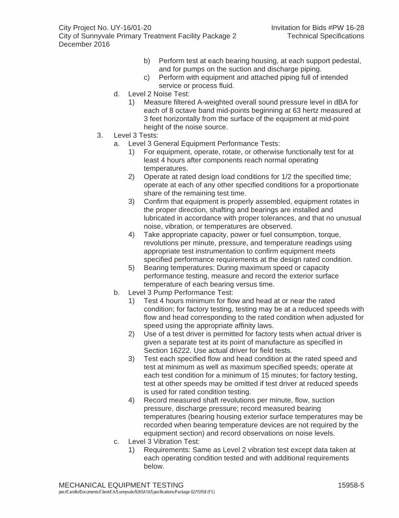
City Project No. UY-16/01-20 Invitation for Bids #PW 16-28City of Sunnyvale Primary Treatment Facility Package 2 Technical SpecificationsDecember 2016
MECHANICAL EQUIPMENT TESTING 15958-5 pw://Carollo/Documents/Client/CA/Sunnyvale/9265A10/Specifications/Package 02/15958 (FS)
b) Perform test at each bearing housing, at each support pedestal, and for pumps on the suction and discharge piping.
c) Perform with equipment and attached piping full of intended service or process fluid.
d. Level 2 Noise Test:1) Measure filtered A-weighted overall sound pressure level in dBA for
each of 8 octave band mid-points beginning at 63 hertz measured at 3 feet horizontally from the surface of the equipment at mid-point height of the noise source.
3. Level 3 Tests:a. Level 3 General Equipment Performance Tests:
1) For equipment, operate, rotate, or otherwise functionally test for at least 4 hours after components reach normal operating temperatures.
2) Operate at rated design load conditions for 1/2 the specified time; operate at each of any other specified conditions for a proportionateshare of the remaining test time.
3) Confirm that equipment is properly assembled, equipment rotates in the proper direction, shafting and bearings are installed and lubricated in accordance with proper tolerances, and that no unusual noise, vibration, or temperatures are observed.
4) Take appropriate capacity, power or fuel consumption, torque, revolutions per minute, pressure, and temperature readings using appropriate test instrumentation to confirm equipment meets specified performance requirements at the design rated condition.
5) Bearing temperatures: During maximum speed or capacity performance testing, measure and record the exterior surface temperature of each bearing versus time.
b. Level 3 Pump Performance Test:1) Test 4 hours minimum for flow and head at or near the rated
condition; for factory testing, testing may be at a reduced speeds with flow and head corresponding to the rated condition when adjusted for speed using the appropriate affinity laws.
2) Use of a test driver is permitted for factory tests when actual driver is given a separate test at its point of manufacture as specified in Section 16222. Use actual driver for field tests.
3) Test each specified flow and head condition at the rated speed and test at minimum as well as maximum specified speeds; operate at each test condition for a minimum of 15 minutes; for factory testing, test at other speeds may be omitted if test driver at reduced speeds is used for rated condition testing.
4) Record measured shaft revolutions per minute, flow, suction pressure, discharge pressure; record measured bearing temperatures (bearing housing exterior surface temperatures may be recorded when bearing temperature devices are not required by the equipment section) and record observations on noise levels.
c. Level 3 Vibration Test:1) Requirements: Same as Level 2 vibration test except data taken at
each operating condition tested and with additional requirements below.
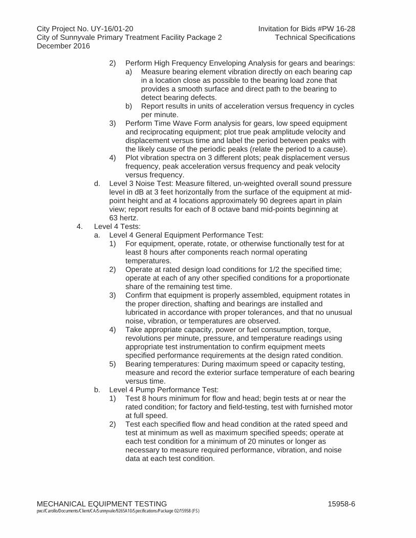
City Project No. UY-16/01-20 Invitation for Bids #PW 16-28City of Sunnyvale Primary Treatment Facility Package 2 Technical SpecificationsDecember 2016
MECHANICAL EQUIPMENT TESTING 15958-6 pw://Carollo/Documents/Client/CA/Sunnyvale/9265A10/Specifications/Package 02/15958 (FS)
2) Perform High Frequency Enveloping Analysis for gears and bearings:a) Measure bearing element vibration directly on each bearing cap
in a location close as possible to the bearing load zone that provides a smooth surface and direct path to the bearing to detect bearing defects.
b) Report results in units of acceleration versus frequency in cycles per minute.
3) Perform Time Wave Form analysis for gears, low speed equipment and reciprocating equipment; plot true peak amplitude velocity and displacement versus time and label the period between peaks with the likely cause of the periodic peaks (relate the period to a cause).
4) Plot vibration spectra on 3 different plots; peak displacement versus frequency, peak acceleration versus frequency and peak velocity versus frequency.
d. Level 3 Noise Test: Measure filtered, un-weighted overall sound pressure level in dB at 3 feet horizontally from the surface of the equipment at mid-point height and at 4 locations approximately 90 degrees apart in plainview; report results for each of 8 octave band mid-points beginning at 63 hertz.
4. Level 4 Tests:a. Level 4 General Equipment Performance Test:
1) For equipment, operate, rotate, or otherwise functionally test for at least 8 hours after components reach normal operating temperatures.
2) Operate at rated design load conditions for 1/2 the specified time; operate at each of any other specified conditions for a proportionate share of the remaining test time.
3) Confirm that equipment is properly assembled, equipment rotates in the proper direction, shafting and bearings are installed and lubricated in accordance with proper tolerances, and that no unusual noise, vibration, or temperatures are observed.
4) Take appropriate capacity, power or fuel consumption, torque, revolutions per minute, pressure, and temperature readings using appropriate test instrumentation to confirm equipment meets specified performance requirements at the design rated condition.
5) Bearing temperatures: During maximum speed or capacity testing, measure and record the exterior surface temperature of each bearing versus time.
b. Level 4 Pump Performance Test:1) Test 8 hours minimum for flow and head; begin tests at or near the
rated condition; for factory and field-testing, test with furnished motor at full speed.
2) Test each specified flow and head condition at the rated speed and test at minimum as well as maximum specified speeds; operate at each test condition for a minimum of 20 minutes or longer as necessary to measure required performance, vibration, and noise data at each test condition.

City Project No. UY-16/01-20 Invitation for Bids #PW 16-28City of Sunnyvale Primary Treatment Facility Package 2 Technical SpecificationsDecember 2016
MECHANICAL EQUIPMENT TESTING 15958-7 pw://Carollo/Documents/Client/CA/Sunnyvale/9265A10/Specifications/Package 02/15958 (FS)
3) Record measured shaft revolutions per minute, flow, suction pressure, discharge pressure; record measured bearingtemperatures (bearing housing exterior surface temperatures may be recorded when bearing temperature devices not required by the equipment section) and record observations on noise levels.
4) Bearing temperatures: During maximum speed or capacity testing, measure and record the exterior surface temperature of each bearing versus time.
5) Perform efficiency and/or Net Positive Suction Head Required (NPSHr) and/or priming time tests when specified in the equipment section in accordance with the appropriate HI standard and as follows:a) Perform NPSHr testing at maximum rated design speed, head
and flow with test fluids at ambient conditions; at maximum rated speed, test at 15 percent above rated design flow, and 25 percent below rated design flow.
b) Perform efficiency testing with test fluids at maximum rated speed.
c) Perform priming time testing with test fluids at maximum rated speed.
c. Level 4 Vibration Test: Same as Level 3 vibration test.d. Level 4 Noise Test: Same as Level 3 Noise Test except with data taken at
each operating condition tested.
J. Variable speed equipment tests: 1. Establish performance over the entire speed range and at the average
operating condition.2. Establish performance curves for the following speeds:
a. The speed corresponding to the rated maximum capacity.b. The speed corresponding to the minimum capacity.c. The speed corresponding to the average operating conditions.
K. Pump tests, all levels of testing:1. Test in accordance with the following:
a. Applicable HI Standards. b. This Section.c. Equipment sections.
2. Test tolerances: In accordance with appropriate HI Standards, except the following modified tolerances apply:a. From 0 to plus 5 percent of head at the specified flows.b. From 0 to plus 5 percent of flow at the rated design point head.c. No negative tolerance for the efficiency at the specified flows.d. No positive tolerance for vibration limits. Vibration limits and test methods
in HI Standards do not apply, use limits, and methods specified in this or other Sections of the Specifications.
L. Drivers tests:1. Test motors as specified in Section 16222. 2. Test other drivers as specified in the equipment section.

City Project No. UY-16/01-20 Invitation for Bids #PW 16-28City of Sunnyvale Primary Treatment Facility Package 2 Technical SpecificationsDecember 2016
MECHANICAL EQUIPMENT TESTING 15958-8 pw://Carollo/Documents/Client/CA/Sunnyvale/9265A10/Specifications/Package 02/15958 (FS)
M. Noise requirements and control: 1. Perform noise tests in conjunction with vibration test analysis.2. Make measurements in relation to reference pressure of 0.0002 microbar.3. Make measurements of emitted noise levels on sound level meter meeting or
exceeding ANSI S1.4, Type II.4. Set sound level meter to slow response.5. Unless otherwise specified, maximum free field noise level not to exceed
85 dBA measured as sound pressure level at 3 feet from the equipment.
N. Pressure testing:1. Hydrostatically pressure test pressure containing parts at the appropriate
standard or code required level above the equipment component specified design pressure or operating pressure, whichever is higher.
O. Inspection and balancing:1. Statically and dynamically balance each of the individual rotating parts as
required to achieve the required field vibration limits.2. Statically and dynamically balance the completed equipment rotating assembly
and drive shaft components.3. Furnish copies of material and component inspection reports including
balancing reports for equipment system components and for the completed rotating assembly.
P. Critical speed of rotating equipment:1. Satisfy the following:
a. The first lateral and torsional critical speed of all constant, variable, and 2-speed driven equipment that is considered rigid such as horizontal pumps, all non-clog pumps, blowers, air compressors, and engines shall be at least 25 percent above the equipment's maximum operating speed.
b. The first lateral and torsional critical speed of all constant, variable, and 2-speed driven equipment that is considered flexible or flexibly mounted such as vertical pumps (vertical in-line and vertical non-clog pumps excluded) and fans shall at least 25 percent below the equipment's lowest operating speed.
c. The second lateral and torsional critical speed of all constant, variable, and 2-speed equipment that is considered flexible or flexibly mounted shall be at least 25 percent above the maximum operating speed.
Q. Vibration tests:1. Definitions:
a. Root mean square: for pumps operating at speeds greater than 600 rpm, the vibration measurement shall be measured as the overall velocity in inches per second root mean square (RMS).
b. Peak-to-peak displacement: The root mean squared average of the peak-to-peak displacement multiplied by the square root of 2.
c. Peak velocity: The root mean squared average of the peak velocity multiplied by the square root of 2.
d. Peak acceleration: The root mean squared average of the peak acceleration multiplied by the square root of 2.
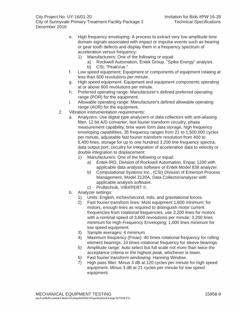
City Project No. UY-16/01-20 Invitation for Bids #PW 16-28City of Sunnyvale Primary Treatment Facility Package 2 Technical SpecificationsDecember 2016
MECHANICAL EQUIPMENT TESTING 15958-9 pw://Carollo/Documents/Client/CA/Sunnyvale/9265A10/Specifications/Package 02/15958 (FS)
e. High frequency enveloping: A process to extract very low amplitude time domain signals associated with impact or impulse events such as bearing or gear tooth defects and display them in a frequency spectrum ofacceleration versus frequency:1) Manufacturers: One of the following or equal:
a) Rockwell Automation, Entek Group, "Spike Energy" analysis.b) CSI, "PeakVue."
f. Low speed equipment: Equipment or components of equipment rotating at less than 600 revolutions per minute.
g. High speed equipment: Equipment and equipment components operating at or above 600 revolutions per minute.
h. Preferred operating range: Manufacturer's defined preferred operating range (POR) for the equipment.
i. Allowable operating range: Manufacturer's defined allowable operating range (AOR) for the equipment.
2. Vibration instrumentation requirements:a. Analyzers: Use digital type analyzers or data collectors with anti-aliasing
filter, 12 bit A/D converter, fast fourier transform circuitry, phase measurement capability, time wave form data storage, high frequency enveloping capabilities, 35 frequency ranges from 21 to 1,500,000 cycles per minute, adjustable fast fourier transform resolution from 400 to 6,400 lines, storage for up to one hundred 3,200 line frequency spectra, data output port, circuitry for integration of acceleration data to velocity or double integration to displacement:1) Manufacturers: One of the following or equal:
a) Entek-IRD, Division of Rockwell Automation, Enpac 1200 withapplicable data analysis software or Entek Model 838 analyzer.
b) Computational Systems Inc., (CSI) Division of Emerson Process Management, Model 2120A, Data Collector/analyzer with applicable analysis software.
c) Pruftechnik, VIBXPERT II.b. Analyzer settings:
1) Units: English, inches/second, mils, and gravitational forces.2) Fast fourier transform lines: Most equipment 1,600 minimum; for
motors, enough lines as required to distinguish motor current frequencies from rotational frequencies, use 3,200 lines for motors with a nominal speed of 3,600 revolutions per minute; 3,200 lines minimum for High Frequency Enveloping; 1,600 lines minimum for low speed equipment.
3) Sample averages: 4 minimum. 4) Maximum frequency (Fmax): 40 times rotational frequency for rolling
element bearings, 10 times rotational frequency for sleeve bearings.5) Amplitude range: Auto select but full scale not more than twice the
acceptance criteria or the highest peak, whichever is lower.6) Fast fourier transform windowing: Hanning Window.7) High pass filter: Minus 3 dB at 120 cycles per minute for high speed
equipment. Minus 3 dB at 21 cycles per minute for low speed equipment.
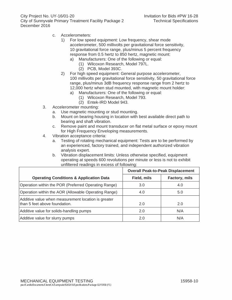
City Project No. UY-16/01-20 Invitation for Bids #PW 16-28City of Sunnyvale Primary Treatment Facility Package 2 Technical SpecificationsDecember 2016
MECHANICAL EQUIPMENT TESTING 15958-10pw://Carollo/Documents/Client/CA/Sunnyvale/9265A10/Specifications/Package 02/15958 (FS)
c. Accelerometers:1) For low speed equipment: Low frequency, shear mode
accelerometer, 500 millivolts per gravitational force sensitivity,10 gravitational force range, plus/minus 5 percent frequency response from 0.5 hertz to 850 hertz, magnetic mount:a) Manufacturers: One of the following or equal:
(1) Wilcoxon Research, Model 797L.(2) PCB, Model 393C.
2) For high speed equipment: General purpose accelerometer, 100 millivolts per gravitational force sensitivity, 50 gravitational force range, plus/minus 3dB frequency response range from 2 hertz to 12,000 hertz when stud mounted, with magnetic mount holder:a) Manufacturers: One of the following or equal:
(1) Wilcoxon Research, Model 793.(2) Entek-IRD Model 943.
3. Accelerometer mounting:a. Use magnetic mounting or stud mounting.b. Mount on bearing housing in location with best available direct path to
bearing and shaft vibration.c. Remove paint and mount transducer on flat metal surface or epoxy mount
for High Frequency Enveloping measurements.4. Vibration acceptance criteria:
a. Testing of rotating mechanical equipment: Tests are to be performed by an experienced, factory trained, and independent authorized vibration analysis expert.
b. Vibration displacement limits: Unless otherwise specified, equipment operating at speeds 600 revolutions per minute or less is not to exhibit unfiltered readings in excess of following:
Operating Conditions & Application Data
Overall Peak-to-Peak Displacement
Field, mils Factory, mils
Operation within the POR (Preferred Operating Range) 3.0 4.0
Operation within the AOR (Allowable Operating Range) 4.0 5.0
Additive value when measurement location is greater than 5 feet above foundation. 2.0 2.0
Additive value for solids-handling pumps 2.0 N/A
Additive value for slurry pumps 2.0 N/A

City Project No. UY-16/01-20 Invitation for Bids #PW 16-28City of Sunnyvale Primary Treatment Facility Package 2 Technical SpecificationsDecember 2016
MECHANICAL EQUIPMENT TESTING 15958-11pw://Carollo/Documents/Client/CA/Sunnyvale/9265A10/Specifications/Package 02/15958 (FS)
c. Vibration velocity limits: Unless otherwise specified, equipment operating at speeds greater than 600 revolutions per minute is not to exceed the following peak velocity limits:
HI Pump Type HorsepowerField Test Factory Test
Overall RMS Overall RMSHorizontal Solids Handling Centrifugal Pumps
Below 33 hp 0.25 0.28
Horizontal and Vertical In-Line Centrifugal Pumps (other than Non-Clog type)Vertical Solids Handling Centrifugal Pumps
Between 33 and 100 hp
0.28 0.31
100 hp and above 0.31 0.34Below 33 hp 0.30 0.33
Vertical Turbine, Mixed Flow, and Propeller Pumps
Between 33 and 100 hp
0.32 0.35
100 hp and above 0.34 0.35Non-Solids Handling CentrifugalPumpsHI Types BB1, BB2, BB3, BB4, BB5, OH1, OH2, OH3, OH4, OH5, and OH7
Below 268 hp 0.15 0.19268 hp and above 0.19 0.22
Vertical Turbine, Mixed Flow, and Propeller Pumps HI Types VS1, VS2, VS3, VS4, VS5, VS6, VS7, and VS8
Below 268 hp 0.13
Gear Reducers, Radial 268 hp and above 0.17Slurry Pumps 0.25 0.30Motors See Applicable Motor
SpecificationSee Applicable
Motor SpecificationGear Reducers, Radial Not to exceed
AGMA 6000-B96 limitsNot to exceed
AGMA 6000-B96 limits
Other Reducers, Axial 0.1 N/Ad. Equipment operation: Measurements are to be obtained with equipment
installed and operating within capacity ranges specified and without duplicate equipment running.
e. Additional criteria:1) No narrow band spectral vibration amplitude components, whether
sub-rotational, higher harmonic, or synchronous multiple of running speed, are to exceed 40 percent of synchronous vibration amplitude component without manufacturer's detailed verification of origin and ultimate effect of such excitation.
2) The presence of discernable vibration amplitude peaks in Test Level 2 or 3 vibration spectra at bearing inner or outer race frequencies shall be cause for rejection of the equipment.
City Project No. UY-16/01-20 Invitation for Bids #PW 16-28City of Sunnyvale Primary Treatment Facility Package 2 Technical SpecificationsDecember 2016
MECHANICAL EQUIPMENT TESTING 15958-12pw://Carollo/Documents/Client/CA/Sunnyvale/9265A10/Specifications/Package 02/15958 (FS)
3) For motors, the following shall be cause for rejection:a) Stator eccentricity evidenced by a spectral peak at 2 times
electrical line frequency that is more than 40 percent of the peak at rotational frequency.
b) Rotor eccentricity evidenced by a spectral peak at 2 times electrical line frequency with spectra side bands at the pole pass frequency around the 2 times line frequency peak.
c) Other rotor problems evidenced by pole pass frequency side bands around operating speed harmonic peaks or 2 times line frequency side bands around rotor bar pass frequency or around 2 times the rotor bar pass frequency.
d) Phasing problems evidenced by 1/3 line frequency side band spectral peaks around the 2 times electrical line frequency peak.
4) The presence of peaks in a High-Frequency Enveloping spectra plot corresponding to bearing, gear, or motor rotor bar frequencies or harmonics of these frequencies shall be cause for equipment rejection; since inadequate lubrication of some equipment may be a cause of these peaks, lubrication shall be checked, corrected as necessary and the high-frequency envelope analysis repeated.
5. Vibration testing results presentation:a. Provide equipment drawing with location and orientation of measurement
points indicated.b. For each vibration measurement take and include appropriate data on
equipment operating conditions at the time vibration data is taken; for pumps, compressors, and blowers record suction pressure, discharge pressure, and flow.
c. When Vibration Spectra Data required:1) Plot peak vibration velocity versus frequency in cycles per minute.2) Label plots showing actual shaft or part rotation frequency, bearing
inner and outer race ball pass frequencies, gear mesh frequencies and relevant equipment excitation frequencies on the plot; label probable cause of vibration peaks whether in excess of specification limits or not.
3) Label plots with equipment identification and operating conditions such as tag number, capacity, pressure, driver horsepower, and point of vibration measurement.
4) Plot motor spectra on a log amplitude scale versus frequency.d. For low-speed equipment, plot peak vibration displacement versus
frequency as well as velocity versus frequency.e. Provide name of manufacturer and model number of the vibration
instrumentation used, including analyzer and accelerometer used together with mounting type.
3.02 PLANNING PHASE
A. Submit test plans as specified in Section 01756 and this Section: 1. Indicate test start time and duration, equipment to be tested, other equipment
involved or required; temporary facilities required, number and skill or trade of personnel involved; safety issues and planned safety contingencies;
City Project No. UY-16/01-20 Invitation for Bids #PW 16-28City of Sunnyvale Primary Treatment Facility Package 2 Technical SpecificationsDecember 2016
MECHANICAL EQUIPMENT TESTING 15958-13pw://Carollo/Documents/Client/CA/Sunnyvale/9265A10/Specifications/Package 02/15958 (FS)
anticipated effect on Owner's existing equipment and other information relevant to the test.
2. Provide locations of all instruments to be used for testing. Provide calibration records for all instrumentation.
3.03 COMMISSIONING PHASE
A. Source testing: 1. Witnessing not required unless specified otherwise in equipment section.2. Witnessed tests: Schedule test date and notify Engineer at least 30 days prior
to start of test.3. Test equipment as specified in Section 01756 and equipment sections.4. Test fluids as specified in Section 01756. 5. Submit reports as specified in Section 01756.
B. Installation testing: 1. Test equipment as specified in Section 01756 and equipment sections.
C. Functional testing: 1. Witnessing required as specified in Section 01756. 2. Schedule test date and notify Engineer at least 7 days prior to start of test. 3. Test equipment as specified in equipment sections. Test fluids as specified in
Section 01756. 4. Submit reports as specified in Section 01756.
D. Clean Water Facility Testing: 1. Test equipment as specified in Section 01756 and equipment sections.
E. Closeout documentation: 1. Provide closeout documentation as specified in Section 01756 and equipment
sections.
3.04 PROCESS START-UP PHASE
A. Process start-up: 1. Process start-up equipment as specified in Section 01756 and equipment
sections.
B. Process Operational Period: 1. Operate equipment as specified in Section 01756 and equipment sections.2. Test fluids as specified in Section 01756.
END OF SECTION