Section 11 AMERICAN Linings and Coatings2-2-17).pdf · AMERICAN Linings for Pipe and Fittings...
17
Section 11 AMERICAN Linings and Coatings
Transcript of Section 11 AMERICAN Linings and Coatings2-2-17).pdf · AMERICAN Linings for Pipe and Fittings...
Section 11
AMERICANLinings andCoatings

AMERICAN Liningsfor Pipe and Fittings
Cement-mortar lining for ductile ironpipe and ductile and gray iron fittings for water service is in accordance with ANSI/AWWA C104/A21.4. Cement-lined pipe is also furnished forsome sewage service and a number of otherapplications. In fact, most pipe furnished iscement lined, providing improved flow characteristics and the required protectionagainst internal corrosion. The cement lining is satisfactory for temperatures up to 212°F. If asphaltic seal coat is furnished, the lining is only adequate for temperatures up to 150°F. For other services contact AMERICAN regarding temperature limitations of cement lining. The first recorded installation of cement-lined gray iron pipe was in 1922 at Charleston, S.C. This lining was developedby the Charleston Commission of Public Works in cooperation with American Cast Iron Pipe Company. Since this beginning, AMERICAN has furnished most of its pipewith cement lining. The lining is applied centrifugally with the speed of rotation designed to produce a smooth waterway surface, minimal voids, yet retaining enough moisture for proper curing. AMERICAN cement-lined pipe and fittings are listed by
ANSI/NSF Standard 61 for potable water contact. Flow tests on cement-lined pipe undervarying service conditions have establishedthat the Hazen-Williams flow coefficient remains as expected at about 140, and flowtests on cement-lined, large-diameter AMERICAN Ductile Iron pipe have confirmed flow coefficients much higher than 140.
Handling Cement-Lined Pipe andFittings Pipe and fittings with cement lining should be handled with rubber-covered hooks or other type equipment to prevent damage to the cement lining. Bare fork lift arms or bare hooks should not be inserted into open ends.
Characteristics of Cement LiningAWWA C104 allows for surface crazing and cracks of a specified nature and magnitude.Occasionally cracks and looseness in linings may occur prior to installation, particularlywhere pipe is stored for a considerable time. Many years’ experience with cementlinedpipe and fittings has verified that this condition is not detrimental to the perfor-
11-1
The principal standard covering cement lining is ANSI/AWWA C104/A21.4. Thisand other standards are referenced throughout this Section either by the full
ANSI/AWWA designation or by only the AWWA numbering, such as AWWA C104.
Cement Lining
Along with technical and metallurgicaladvancement in piping materials, research on lining requirements for pipe and fittings has resulted in the development of linings to meet many different service requirements. AMERICAN offers several types of linings, the most common being cement lining.Pipe and fittings furnished by AMERICANare offered unlined or with linings as follows:
1. Cement Lined per AWWA C104. 2. Asphaltic Lined per AWWA C110, C115 or C151. 3. Fusion-Bonded Epoxy (for 4”-16”Fastite fittinigs) per AWWAA C116. 4. PROTECTO 401 Lined - Ceramic Epoxy Lined. 5. Special Lining - for unusual service conditions

mance and effectiveness of the lining. When a cement-lined pipe is placed in service and filled with water, two reactions begin immediately. The first is a gradual elimination of the temperature differential between pipe and lining, thus eliminating any stresses in the lining due to this condition. Secondly, the lining begins to absorb water. Water is absorbed into the pores of the cement and into the capillary channels of the calcium silicate gel. The water absorption causes the lining to swell, restoring it to intimate contact with the pipe wall and virtually closing any cracks present in the lining. This swelling process is relatively slow, taking up to several weeks for the lining to be restored to its maximum volume. This process has been demonstrated on a number of occasions to the satisfaction of customers, contractors and engineers by immersing a pipe or fitting in water for one or two weeks. After a period of exposure to water, not only does the lining tighten against the pipe wall and the cracks close, but finally the surfaces of the cracks actually re-bond. This occurs by a process called autogenous healing.This phenomenon, long recognized by the cement industry, has been documented by laboratory tests to occur in cement-lined ductile pipe. In one test, a 48” ductile iron pipe with severely cracked cement lining was held half full of water for several months. At the end of that period, the lining both above and below the water surface was found to be tight, with all cracks either healed completely or sealed by the formation of calcium carbonate. Field inspections of lines that have been in service for many years have verified the laboratory results; cement linings do tighten and heal in service and provide the corrosion protection to the pipe and the high flow coefficients for which they were designed.
Field Repair of Damaged CementLinings Cement lining will withstand normal handling; nevertheless, pipe or fittings maybe found at times to have damaged liningswhich need to be repaired before placing inservice.
AWWA C104 provides that damagedlining may be repaired, and the following repair procedure is recommended: 1. Cut out the damaged lining to themetal. Square the edges. 2. Thoroughly wet the cut-out area and adjoining lining. 3. With the damaged area cleaned andthe adjoining lining wet, spread the mortar(see recommended mix below) evenly overthe area to be patched. (See Table No. 11-1, next page, for lining thicknesses.) After thelining has become firm and adheres well tothe surface, finish it with a wet 3” or 4” paint brush or similar soft bristle brush. 4. The repaired lining should be kept moist by tying canvas, wet burlap, or otherwrap over the ends of the pipe or fitting forat least 24 hours. As an alternative the repaired lining may be seal coated with a cut back type of asphaltic seal coating. This must be sprayed or brushed on within five to 30 minutes after lining. To maintain NSFcertification, patch must be made using a NSF certified cement for 4” pipe and larger,or the patch must be topcoated with NSF certified asphalt paint.
Recommended Cement Mix Cement mix by volume: 3 Parts Portland Cement; 2 Parts Clean Sand; necessary water for slump of 5” to 8”. The sand should be free of clay and screened through a No. 20 Screen.
Precautions 1. Mortar for lining should not be usedafter it has been mixed for more than one hour. 2. Too rapid a loss of moisture from fresh linings due to hot weather or high wind will prevent proper cure, resulting in the lining being soft and powdery. To prevent this loss of moisture, (a) do not line hot castings and (b) close the ends of the castings with wet burlap. 3. Fresh linings that become frozen will not be serviceable. Avoid lining in freezingweather
11-2

11-3
Table No. 11-1
Sizein.
NominalPipe Length
ft. MinimumThickness
in.
WeightPer Foot
lb
WeightPer Length
lb
MinimumThickness
in.
WeightPer Foot
lb
WeightPer Nominal
Length lb
14 18 1/16 11.87 117 1/8 11.71 1131 16 20 1/16 11.30 126 1/8 12.57 1151 18 20 1/16 11.74 135 1/8 13.45 1169 10 20 1/16 12.15 143 1/8 14.28 1186 12 20 1/16 12.57 151 1/8 15.12 1102 14 20 3/32 14.49 190 3/16 18.93 1179 16 20 3/32 15.13 103 3/16 10.19 1204 18 20 3/32 15.76 115 3/16 11.47 1229 20 20 3/32 16.40 128 3/16 12.73 1255 24 20 3/32 17.68 154 3/16 15.31 1306 30 20 1/8 12.76 255 1/4 25.42 1508 36 20 1/8 15.31 306 1/4 30.51 1610 42 20 1/8 17.82 356 1/4 35.53 1711 48 20 1/8 20.35 407 1/4 40.60 1812 54 20 1/8 22.89 458 1/4 45.68 1914 60 20 1/8 24.71 494 1/4 49.32 1986 64 20 1/8 26.35 527 1/4 52.61 1052
Cement LiningANSI/AWWA C104/A21.4Thicknesses and Weights
Standard Thickness Double Thickness
Weights are based on the minimum lining thicknesses for minimum pressure classes of Fastite ductile iron pipe.Actual lengths and weights may differ from above. Linings may taper at the ends. AMERICAN recommends the use of standard thickness cement lining per AWWA C104 for all normal installations.
This 64” Ductile Iron Fastite Joint water transmission main was furnished with standardcement lining for continuing high flow performance.

Pipe and fittings lined with the following types of coatings are available from AMERICAN on a special order basis. For more detailed information regarding lining selection, application parameters and typical field topcoats, please contact AMERICAN.
ASPHALTIC LINING AMERICAN furnishes some pipe and fittings lined with an asphaltic material in accordance with AWWA C110, C115, C153and C151. After thoroughly drying, the lining has no deleterious effect upon the quality, color, taste or odor of potable water.Asphaltic lining is not normally used in waterservice; the majority of ductile water lines are cement lined. Asphaltic lining or seal-coat, if furnished, on cement lining is adequate fortemperatures up to 150°F.
Protecto 401 LINING AMERICAN can furnish 4”-64” Protecto 401 Ceramic Epoxy-lined ductile iron pipe and fittings. This third-party-designed and -applied lining is amine-cured with novalac and ceramic quartz pigment for an approximately 40-milthick, high-build lining.Protecto 401 Ceramic Epoxy™ Standard for Lining Ductile Iron Pipe and Fittings for Sewer Service Protecto 401-lined ductile iron pipe and fittings provide the maximum protection and the strength necessary to do the job in tough sewer pipe applications. Protecto 401 has been successfully used in hundreds of sanitary sewer applications and has been proven with both laboratory testing and years of actual sewer service on all sizes of ductile iron pipe and fittings. The development of Protecto 401 wasbegun in 1979. The first Protecto 401-linedductile iron sewer pipe was lined and placed in service in 1981. Since then hundreds of miles of ductile iron sewer pipe have been lined with Protecto 401 with no lining failure. Because Protecto 401 Ceramic Epoxy Lining was designed and is used as protection for ductile iron sanitary sewer pipe, it provides the reliability of
cement mortar lining with the excellent corrosion protection of novalac epoxy. This concentration of effort has resulted in performance unparalleled by other linings. Protecto 401 has been tested extensively. Because the specifications for application and testing of Protecto 401 Ceramic Epoxy have been developed for ductile iron pipe using test data and performance history, no deviations from the specification shall be permitted without prior written approval of the lining manufacturer.If required, third-party inspection of Protecto 401 Ceramic Epoxy-lined ductile iron pipe shall be done only after written notice to the applicator of Protecto 401 Ceramic Epoxy. Any third-party inspection shall be accomplished using standard Protecto 401 Ceramic Epoxy Quality Control Procedures. Protecto 401 is applied to the interior of ductile pipe and fittings utilizing specializedapplication equipment and a stringent specification. The lining is designed to be applied at a nominal 40 mils thickness. A nondestructive pinhole detection test and a thickness test is performed to insure a sound, chemically resistant protective lining for ductile iron pipe and fittings. Protecto 401 is intended for use in domestic sanitary sewage lines. Chemical injection for odor control may damage pipe, gaskets and/or protective linings and should be undertaken with extreme caution. Requests for industrial sewer applications of Protecto 401-lined ductile pipe and fittings should be made to a pipe marketing representative for individual recommendations. Ductile iron pipe lined with Protecto 401 Ceramic Epoxy™ can only be pushed when using a restrained joint system that does not allow the spigot to contact the bell shoulder. The pipe may be pulled using restrained joint pipe or restraining gaskets as restraints. Restraining gaskets must never be pushed; nor should the pipe be homed all the way to the bell shoulder with or without restraining gaskets. Pushing or pulling ductile iron pipe lined with Protecto 401 Ceramic Epoxy™using any other technique may damage the lining. Consult Induron’s
11-4
Other Linings Available From AMERICAN

11-5
brochure for product application concerning pushing or pulling operations. The practice of pulling a metal mandrel through Protecto 401 Ceramic Epoxy™ lined ductile iron pipe is not recommended and should be considered carefully. Most mandrels have legs with sharp edges produced by wear. Mandrels are usually the size of the interior diameter of PVC pipe, and because ductile iron pipes are larger, these mandrels tend to ride on the edge of the center legs that may result in damage to the lining. For additional information, contact Induron at 1-888-SPEC401. Reprinted with permission of Induron Protective Coatings.
Protecto 401 Ceramic Epoxy™ Standard Specification for Lining Ductile Iron Pipe for Sewer Service
I. Condition of Ductile Iron Prior to Surface Preparation All ductile pipe and fittings shall be delivered to the application facility without asphalt, cement lining or any other lining on the interior surface. Because removal of old linings may not be possible, the intent of this specification is that the entire interior of the ductile iron pipe and fittings shall not have been lined with any substance prior to the application of the specified lining material, and no coating shall have been applied to the first six inches of the exterior of the spigot ends. II. Lining Material The Standard of Quality is Protecto 401 Ceramic Epoxy. The material shall be an amine-cured novalac epoxy containing at least 20% by volume of ceramic quartz pigment. Any request for substitution must be accompanied by a successful history of lining pipe and fittings for sewer service, a test report verifying the following properties, and a certification of thetest results. A. A permeability rating of 0.00 when tested according to Method A of ASTM E-96-66, Procedure A with a test duration of 30 days.
B. The following test must be run on coupons from factory-lined ductile iron pipe:
1.ASTM B-117 Salt Spray (scribed panel) - Results to equal 0.0 undercutting after two years. 2.ASTM G-95 Cathodic Disbondment 1.5 volts @ 77°F. Results to equal no more than 0.5mm undercutting after 30 days. 3.Immersion Testing rated using ASTM D-714-87. a. 20% Sulfuric Acid - No effect after two years. b. 140°F 25% Sodium Hydroxide- No effect after two years. c. 160°F Distilled Water- No effect after two years. d. 120°F Tap Water (scribed panel) - 0.0 undercutting after two years with no effect.C. An abrasion resistance of no more than 3 mils (.075mm) loss after one million cycles using European Standard EN 598: 1994 Section 7.8 Abrasion Resistance. III. Application A. Applicator The lining shall be applied by a certi-fied firm with a successful history of applying linings to the interior of ductile iron pipe and fittings. B. Surface Preparation Prior to abrasive blasting, the entire area to receive the protective compound shall be inspected for oil, grease, etc. Any areas with oil, grease or any substance which can be removed by solvent, shall be solvent cleaned to remove those substances. After the surface has been made free of grease, oil or other substances, all areas to receive the protective compound sshall be abrasive blasted using sand or grit abrasive media. The entire surface to be lined shall be struck with the blast media so that all rust, loose oxides, etc., are removed from the surface. Only slight stains and tightly adhering oxide may be left on the surface. Any area where rust reappears before lining must be reblasted.

11-6
C. Lining After the surface preparation and within 8 hours of surface preparation, the interior of the pipe shall receive 40 mils nominal dry film thickness of Protecto 401. No lining shall take place when the substrate or ambient temperature is below 40 degrees Fahrenheit. The surface also must be dry and dust free. If flange pipe or fittings are included in the project, the lining shall not be used on the face of the flange.D. Coating of Bell Sockets and Spigot Ends Due to the tolerances involved, the gasket area and spigot end up to 6 inches back from the end of the spigot end must be coated with 6 mils nominal, 10 mils maximum using Protecto Joint Compound. The Joint Compound shall be applied by brush to ensure coverage. Care should be taken that the Joint Compound is smooth without excess buildup in the gasket seat or on the spigot ends. Coating of the gasket seat and spigot ends shall be done after the application of the lining.E. Number of Coats The number of coats of lining materialapplied shall be as recommended by the lining manufacturer. However, in no case shall this material be applied above the dry thickness per coat recommended by the lining manufacturer in printed literature. The maximum or minimum time between coats shall be that time recommended by the lining material manufacturer. To prevent delamination between coats, no material shall be used for lining which is not indefinitely recoatable with itself without roughening of the surface.F. Touch-Up & Repair Protecto Joint Compound shall be usedfor touch-up or repair in accordance with manufacturer’s recommendations.IV. Inspection and CertificationA. Inspection 1. All ductile iron pipe and fitting linings shall be checked for thickness using a magnetic film thickness gauge. The thickness testing shall be done using the method outlined in SSPC- PA-2 Film Thickness Rating. 2. The interior lining of all pipe barrels and fittings shall be tested for pinholes with a nondestructive 2,500
volt test. Any defects found shall be repaired prior to shipment. 3. Each pipe joint and fitting shall be marked with the date of application of the lining system along with its numerical sequence of application on that date and records maintained by the applicator of his work.B. Certification The pipe or fitting manufacturer must supply a certificate attesting to the fact that the applicator met the requirements of this specification, and that the material used was as specified.V. Handling Protecto 401-lined pipe and fittings must be handled only from the outside of the pipe and fittings. No forks, chains, straps, hooks, etc., shall be placed inside the pipe and fittings for lifting, positioning or laying. The pipe shall not be dropped or unloaded by rolling. Care should be taken not to let the pipe strike sharp objects while swinging or being off-loaded. Ductile iron pipe should never be placed on grade by use of hydraulic pressure from an excavator bucket or by banging with heavy hammers.
Polybond™ and PolybondPlus™ are no longer available.
FUSION-BONDED EPOXY All 4”-16” Fastite fittings are fusion-bonded-epoxy lined and coated. Fusion-bonded epoxy is furnished in accordance with AWWA C116.
OTHER SPECIAL LININGS Customers can request pipe and fittings with special linings other than those listed above (e.g., glass lining, etc.). Because of the variables and complexities involved in the selection of a proper lining for a given service, AMERICAN invites inquiries for technical assistance, availability and cost.
UNLINED Because some service applications mayrequire unlined pipe & fittings, AMERICAN furnishes any of its products without lining when so specified at time of purchase.

11-7
Several different types of exterior primers for pipe and fittings are available from AMERICAN. Because of variables and complexities involved in the selection and application of a proper coating for a given service, AMERICAN invites inquiries for technical assistance.
AMERICAN furnishes most pipe and fittings coated outside with an asphaltic coating approximately one mil thick per AWWA C151 for ductile iron pipe, AWWA C115 for flanged pipe and AWWA C110 and C153 for fittings. All across the United States ductile iron and gray iron pipe and fittings with this standard coating have provided trouble-free service for decades. Unless otherwise specified, an asphaltic coating is applied to the outside of all pipe and fittings manufactured by AMERICAN. The asphaltic coating works in conjuction with manufacturing annealing scale to provide a barrier to corrosion. If soils are deemed to be corrosive to ductile iron pipe when evaluated in accordance with the Design Decision ModelTM (DDMTM*) or Appendix A of AWWA C105, zinc coating with or without V-Bio polyethylene wrap should be used. Asphaltic coating is not compatible with most top coats. See the following alternative coating and primer recommendations.
MCU UNIVERSAL PRIMER(Moisture-Cured Urethane) This is a quality, fast-curing, surface tolerant, immersion-grade, moisture-cured urethane (MCU) specially developed and tested for iron substrates. This coating isessentially a universal primer compatible with all major generic topcoats, including acrylics, epoxies, polyurethanes and moisture-cured urethane topcoats. It can also be topcoated with solvent or water-based asphaltic coatings. For the above reasons, it is well suited for most applications, including where the generic topcoats or end uses may not be known.
Other advantages include a very tough, damage-resistant film resulting in less handling and shipping damage and less touch-up and repair in the field than traditional epoxy primers used in the past. This primer does not have a maximum recoat window and does not require field blast cleaning, as long as the surface is clean and free of dust. This primer is considered a high-performance, chemical resistant coating suitable for immersion and non-immersion services. Refer to AMERICAN Recommended and Preferred Primer System - Universal Primer (Moisture-cured urethane) for more information and advantages.
PHENOLIC ALKYD PRIMER This is a fast-drying, lead- and chromate-free, corrosion-resistant primer formulated to accept a wide variety of topcoats. It is well suited for applications where the generic topcoats are unknown but its service is limited to atmospheric exposure. Refer to AMERICAN Alkyd-Phenolic Primer. NOTE: NOT RECOMMENDED FOR IMMERSION. MUST ALLOW UP TO 30 DAYS OF CURING BEFORE TOPCOATINGWITH CERTAIN COATINGS.
EPOXY PRIMER This is a high-solids, chemical- and corrosion-resistant coating for protection against abrasion, moisture, corrosive fumes, chemical attack and immersion.
This 30” AMERICAN Ductile Iron Fastite joint treated-water transmission main was furnished and installed—as is most ductile iron pipe—with standard asphaltic coating approximately one mil thick on the outside.
AMERICAN Coatings and Primersfor Pipe and Fittings
*DDMTM (Design Decision ModelTM) developed jointly by Corrpro Companies, Inc., and the Ductile Iron Pipe Research Association. See american–usa.com, dipra.org or corrpro.com for details.

11-8
High-build properties provide outstanding corrosion protection with fewer coats, particularly on edges. Such high solids, high film-build epoxies are compatible with most catalyzed finish coats. Typical (field) finish coatings include: epoxies (amine, polyamide, polyamidoamine, water-borne, coal-tar) and polyurethane. Refer to AMERICAN Polyamidoamine Epoxy Primer. NOTE: AFTER 60 DAYS OF CURING, THIS PRIMER SHOULD BE UNIFORMLY SCARIFIED BY BRUSH-BLASTING WITH FINE ABRASIVE BEFORE TOPCOATING.
OTHER SPECIAL COATINGS AMERICAN can also furnish other special exterior coating systems. Contact
AMERICAN for technical assistance in the selection of special exterior coating systems,lead times and costs. See pages 11-9 through 11-11 for additional information related to metallic zinc coating.
UNCOATED PIPE Because some customer applications may require piping or fittings that have no coating applied to the exterior, AMERICANfurnishes, when specified at time of purchase, any of its products without exterior coatings.
NOTE: AMERICAN also has the ability to furnish other primers, but this may affect price and availability.
MCU Universal PrimerInterior/Exterior/Immersion (Above andBelow Grade)• Single-coat thickness: 3.0-5.0 mils DFT(76-127 microns).• Typical Topcoats: alkyds, aluminums,epoxies, bituminous, polyurethanes andmoisture-cured urethane topcoats.• Specially developed and tested for ironsubstrates.• Single component.• Low-temperature, fast-curing capability.• Can be applied over damp, but not wetsurfaces.• Infinite recoat window, as long as surfaceis clean and free of dust before topcoating.• This primer is compliant with ANSI/NSFStandard 61 as a primer and spigot surfacecoating for pipe, fittings, and valves whencombined with approved topcoats.
OTHER PRIMERS
Alkyd-Phenolic PrimerInterior/Exterior/Non-Immersion (AboveGrade Only)
• Single-coat thickness: 2.0-4.0 mils DFT(50-101 microns).• Typical Topcoats: alkyds, aluminums,epoxies, and urethanes.• Coating must be cured for 30 days beforebeing overcoated with certain topcoats.• This primer is not recommended forimmersion service.• This primer is compliant with NSFStandard 61 as an exterior surface coating only.
Polyamidoamine Epoxy PrimerInterior/Exterior/Immersion (Above andBelow Grade)• Single-coat thickness: 3.0-8.0 mils DFT(76-203 microns).• Typical Topcoats: epoxies and urethanes.• This coating must be lightly blast cleanedbefore topcoating if it has not been exteriorexposed for 60 days or longer.• This primer is compliant with ANSI/NSFStandard 61 for potable water contact forpipe, fittings, and valves when combinedwith approved topcoats.
AMERICAN Cast Iron Pipe CompanyStandard O.D. Shop Primer Systems
RECOMMENDED AND PREFERRED PRIMER

11-9
AMERICAN is proud to introduce the latest advancement in corrosion control for iron pipe, zinc coating. Zinc has been used to effectively eliminate corrosion in iron pipe for more than 50 years. Internationally, this advanced coating system has been used to protect millions of feet of cast and ductile iron pipe in corrosive environments.
AMERICAN began supplying zinc coating for our export orders starting in the early 1980s. Now, we’re pleased to offer this proven system to domestic markets. Zinc coating significantly extends the life of an already rugged and reliable product – ductile iron pipe.
Zinc-Coated Ductile Iron Pipe
Zinc dust was first added to paints for corrosion control as early as 1837. Since then, zinc-rich paints have received widespread acceptance for metallic corrosion control around the world. The water industry first began using zinc coatings on iron pipe in Europe in 1955. As a result of zinc’s widespread use there, the ISO standards 8179 and BSEN 545/598 were both developed and widely adopted.
Beginning in the early 1980s the mass of zinc applied to iron pipe was increased from the original 130 grams per square meter (g/m2) to the current 200 g/m2. This amount, with a protective topcoat, has proven optimal for life extension of iron pipe. Also, in the early 1980s, AMERICAN began supplying the zinc-rich ISO coatings on ductile iron pipe for our international orders.
A Brief History of Zinc Coatings
Key Dates in the Development of Zinc Coatings for Ductile Iron Pipe
1958 Zinc coating was first applied to cast iron pipe in Europe for corrosion protection.
1963 Standard bitumen/coal-tar paint was applied for normal environments in Europe.
1963 Polyethylene sleeve was recommended for soil resistivities of less than 400 ohm-centimeter by French pipe maker Pont-à-Mousson.
1972 Germany and Austria began to standardize the use of zinc coatings on iron pipe.
1982 AMERICAN supplied its first international order with a zinc coating.
1984 All ductile iron manufacturers in the United Kingdom started supplying all newductile iron pipe in the diameter range 80 - 800mm with a zinc coating.
1984 Zinc spray of 130 g/m2 under bitumen paint became common in Europe.
1995 Zinc spray of 200 g/m2 under bitumen paint became the standard in Europe.
The advances in zinc coatings over the past 60 years have resulted in a highly effective corrosion inhibiting product. According to the International Zinc Association, products coated with zinc “areslow to enter the recycling circuit due to the very nature of their durability. The life of zinc-containing products is variable
and can range from 10-15 years for cars or household appliances, to over 100 years for zinc sheet used for roofing.” With a projected lifespan of well over 100 years, zinc coating on ductile iron pipe is the most effective and dependable way to further extend the lifespan of an already rugged and durable product.
Zinc Coatings for Iron Pipe Today

11-10
A Specification for Zinc Coatingon Ductile Iron Pipe
A. Standards: Ductile iron pipe shall conform to AWWA C150 and C151, subject to the following supplemental requirements. The pipe shall be of the diameter and class shown, shall be furnished complete with rubber gaskets as indicated in the Contract Documents, and all specials and fittings shall be provided as required under the Contract Documents. The ductile iron pipe shall be manufactured or supplied by AMERICAN Ductile Iron Pipe or pre-approved equal. Joints shall conform to AWWA C111, cement linings to AWWA C104, fittings to AWWA C153 or C110.
B. Markings: Upon request, the CONTRACTOR shall require the MANUFACTURER to legibly mark specials in accordance with a laying schedule and marking diagram. All other cast marks and other marks shall be in accordance with applicable Standards.
C. Laying Lengths: Pipe laying lengths shall be provided in 20 foot nominal lengths with allowable trim pipe lengths in accordance with AWWA C151 and special shorter lengths provided as required by the Drawings.
D. Joint Design: Ductile iron pipe shall be furnished with push-on joints or push-on restrained joints. Restrained joints shall be AMERICAN Fast-Grip, Flex-Ring, or Lok-Ring.
E. Lining: Except otherwise provided herein, interior surfaces of all ductile iron pipe, fittings, and specials shall be cleaned and lined at the pipe casting facility with a standard thickness cement mortar lining applied in conformity with AWWA C104. A seal coat shall not be applied to the surface of the cement-mortar lining.
F. Coating: The exterior of ductile iron pipe shall be coated with a layer of arc-sprayed zinc per ISO 8179. The mass of the zinc applied shall be 200 g/m2 of pipe surface area. A finishing layer topcoat shall be applied to the zinc. The coating system shall conform in every respect to ISO 8179-1 “Ductile iron pipes - External zinc-based coating - Part 1: Metallic zinc with finishing layer. Second edition 2004-06-01.”
G. Installation: Ductile iron pipe shall be loaded, transported, unloaded, installed, and tested in accordance with AWWA C600.

11-11
Zinc Coated Ductile Iron Pipefor Corrosion Control
V-Bio Polyethylene Encasement
Zinc Basecoat
Asphaltic Topcoat
Zinc is anodic to iron. That means iron is the more stable, more noble, of the two elements. Zinc will cathodically protect the iron pipe as long as zinc is present, and over time, will convert to zinc compounds that provide an enduring passivating layer under the topcoat, which protects the pipe against further corrosive attack. Zinc is an anode, uniformly adhered to the surface of the pipe.

11-12
Product Description V-Bio, the latest advancement in corrosion control for ductile iron pipe, is an enhanced polyethylene encasement that targets anaerobic bacteria on the surface of the pipe and inhibits the formation of corrosion cells under the wrap.
Already known for its corrosion control properties, polyethylene encasement has been used to successfully protect cast and ductile iron pipe in aggressive environments since its first use in a water system in 1958. And now, with V-Bio, this wrap offers even greater protection of the industry’s most dependable, economic and long lasting pipe material.
Key facts about the V-Bio enhanced polyethylene encasement: • Builds on a proven method of corrosion control — polyethylene encasement – that has been protecting iron pipe from aggressive soils since it was first installed in 1958.
• Represents a significant evolutionary advancement in corrosion protection for ductile iron pipe.
• Consists of three layers of co-extruded linear low-density polyethylene (LLDPE) film fused into one.
• Features an inside surface that is infused with a proprietary blend of an anti-microbial compound to mitigate microbiologically influenced corrosion (“MIC”) and a volatile corrosion inhibitor (“VCI”) to control galvanic corrosion.
• Protects against corrosion without consuming or degrading the compound or the corrosion inhibitor. The film’s enhanced properties will last over time.
• Meets all requirements of the American National Standards Institute and the American Water Works Association (ANSI/AWWA C105/A21.5) standard for polyethylene encasement.
• The most advanced method of corrosion control.
For details about V-Bio enhanced polyethylene encasement, ductile iron pipe or the Ductile Iron Pipe Research Association visit: www.dipra.org/v-bio/
V-Bio Enhanced Polyethylene Encasement
11-13
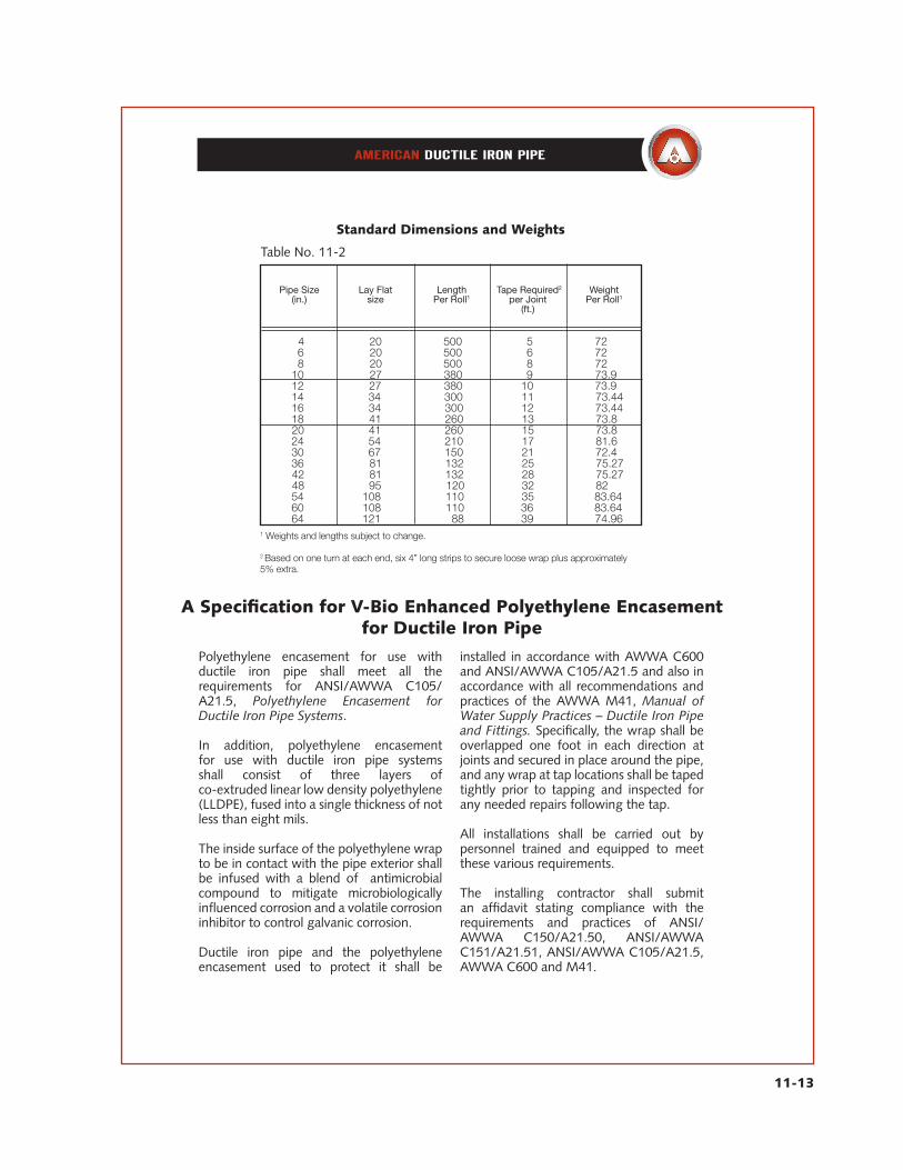
Table No. 11-2
Pipe Size(in.)
Lay Flatsize
LengthPer Roll1
Tape Required2
per Joint(ft.)
WeightPer Roll1
1 4 20 500 5 72 6 20 500 6 72 8 20 500 8 72 10 27 380 9 73.9 12 27 380 10 73.9 14 34 300 11 73.44 16 34 300 12 73.44 18 41 260 13 73.8 20 41 260 15 73.8 24 54 210 17 81.6 30 67 150 21 72.4 36 81 132 25 75.27 42 81 132 28 75.27 48 95 120 32 82 54 108 110 35 83.64 60 108 110 36 83.64 64 121 88 39 74.96
Standard Dimensions and Weights
1 Weights and lengths subject to change.
2 Based on one turn at each end, six 4” long strips to secure loose wrap plus approximately 5% extra.
A Specification for V-Bio Enhanced Polyethylene Encasement for Ductile Iron Pipe
Polyethylene encasement for use with ductile iron pipe shall meet all the requirements for ANSI/AWWA C105/A21.5, Polyethylene Encasement for Ductile Iron Pipe Systems. In addition, polyethylene encasement for use with ductile iron pipe systems shall consist of three layers of co-extruded linear low density polyethylene (LLDPE), fused into a single thickness of not less than eight mils.
The inside surface of the polyethylene wrap to be in contact with the pipe exterior shall be infused with a blend of antimicrobial compound to mitigate microbiologically influenced corrosion and a volatile corrosion inhibitor to control galvanic corrosion.
Ductile iron pipe and the polyethylene encasement used to protect it shall be
installed in accordance with AWWA C600 and ANSI/AWWA C105/A21.5 and also in accordance with all recommendations and practices of the AWWA M41, Manual of Water Supply Practices – Ductile Iron Pipe and Fittings. Specifically, the wrap shall be overlapped one foot in each direction at joints and secured in place around the pipe, and any wrap at tap locations shall be taped tightly prior to tapping and inspected for any needed repairs following the tap. All installations shall be carried out by personnel trained and equipped to meet these various requirements. The installing contractor shall submit an affidavit stating compliance with the requirements and practices of ANSI/AWWA C150/A21.50, ANSI/AWWA C151/A21.51, ANSI/AWWA C105/A21.5, AWWA C600 and M41.

11-14
In areas where severely aggressive soils are encountered, the use of a polyethylenetube or sheet encasement has been proven to provide highly effective, economical protection. The protection against corrosion provided by loose polyethylene is different in several ways and should not be confused with coatings applied directly to the barrel of the pipe. The most significant difference is its ability to protect without creation of concentration cells at holidays. Also, since the encasement is applied when the pipe is actually put in the ground, coating damagedue to shipping, handling, etc., is minimized. As water may be present in the soil around the pipe, water may also be presentbetween the pipe and wrap. Water inside the polyethylene tubing initially bears some characteristics of the soil environment, and corrosion may start. But within a short period of time initial oxidation depletes the oxygen supply in the water, and other electrochemical corrosion reactions also progress to completion. At this point a state of chemical equilibrium is reached. Since the first field installation of polyethylene wrap on gray iron pipe in 1958, installations have been made in severely corrosive soils throughout the United States. The success of the polyethylene encasement procedure developed in the United States has been adopted by several other countries, and an International Standard for Polyethylene Sleeving (ISO- 8180) has been developed. Research by the Ductile Iron Pipe Research Association at several severely corrosive test sites has verified that polyethylene encasement provides a high degree of protection and results in minimal and generally insignificant exterior surface
corrosion of either ductile or gray iron pipe thus protected. These findings have been confirmed by the results of numerous investigations of field installations. Field tests have also indicated that the dielectric capability of polyethylene provides shielding for ductile and gray iron pipe against stray current at most levels encountered in the field. Because polyethylene encasement is apassive method of protecting ductile iron pipe in aggressive soils, it can effect greater reliability and savings than cathodic protection systems which require continualmonitoring, maintenance and other operating expenses, and trained personnel.Cathodic protection systems can also cause collateral harm in some cases to nearby unprotected ferrous structures. For protection in areas of severely aggressive soils, AWWA C105 covers materials and installation procedures for polyethylene encasement of underground installations of ductile iron piping for water and other liquids. Polyethylene wrap in tube or sheet form for piping encasement is manufacturedof virgin polyethylene material conforming to the requirements of ANSI/ASTM Standard Specification D1248. The specified minimum thickness for linear low-density polyethylene film is 0.008 in. (8 mils). The specified minimum thickness for high-density, cross-laminated polyethylene film is 0.004 in. (4 mils). Material, required markings, and installation methods are all in accordance with the requirements of AWWA C105. This standard and more detailed publications by DIPRA regarding loose polyethylene encasement are available from AMERICAN.
Traditional Polyethylene Encasement

11-15
Traditional Polyethylene Tubing and TapeANSI/AWWA C105/A21.5
Tubing in Roll
Installation of Polyethylene Encasement
Installment methods as set forth in ANSI/AWWA C105/A21.5 and DIPRA’s “Polyethelyne Encasement” brochure should be followed.
Table No. 11-3
Pipe Sizein.
Flat Tube†Min. Width
in. Per 1000’of Tube
Per 22’ LongIndividual Tube
Approx. weight (lb.)per 500’ roll 4 mil
high-density cross-laminated P.E.
Tape Required*Per Joint
ft.
4 14 89 2 21 5 6 16 102 3 24 6 8 20 128 3 30 8 0 24 154 4 36 9 12 27 173 4 40 10 14 30 192 5 45 11 16 34 218 5 51 12 18 37 237 6 55 13 20 41 262 6 61 15 24 54 346 8 80 17 30 67 429 10 100 21 36 81 518 12 120 25 42 81 518 12 120 28 48 95 608 14 141 32 54 108 689 16 161 35 60 108 689 16 161 36 64 121 772 18 180 39
Approximate Weight in Pounds8 mil low-density P.E.
*Based on one turn at each end, six 4”–long strips to secure loose wrap plus approximately 5% extra.†Flat tube widths are shown for Fastite, Flex–Ring, Lok–Ring, and MJ Joints. Check AMERICAN for Flat tube widthsrequired for Flex–Lok Joints.The standard color for low–density polyethylene is black. It can also be furnished white, green, red, buff, royal blue, andlavender on special order. The standard color for high–density, cross–laminated polyethylene is white. It can also be furnished black on special order.

APM11—03-01-16