SECTION 10 Analog Input/Output Option Board CJ...508 Memory Allocation The memory allocation about...
18
505 SECTION 10 Analog Input/Output Option Board This section describes how to use Analog Input/Output Option Board. 10-1 General Specifications . . . . . . . . . . . . . . . . . . . . . . . . . . . . . . . . . . . . . . . . . . 506 10-2 Part Names . . . . . . . . . . . . . . . . . . . . . . . . . . . . . . . . . . . . . . . . . . . . . . . . . . . 506 10-3 Installation and Setting . . . . . . . . . . . . . . . . . . . . . . . . . . . . . . . . . . . . . . . . . . 507 10-3-1 Installation . . . . . . . . . . . . . . . . . . . . . . . . . . . . . . . . . . . . . . . . . . . . 507 10-3-2 Setting . . . . . . . . . . . . . . . . . . . . . . . . . . . . . . . . . . . . . . . . . . . . . . . . 507 10-3-3 Removing . . . . . . . . . . . . . . . . . . . . . . . . . . . . . . . . . . . . . . . . . . . . . 507 10-4 Memory Allocation . . . . . . . . . . . . . . . . . . . . . . . . . . . . . . . . . . . . . . . . . . . . . 508 10-4-1 CIO Area Allocation . . . . . . . . . . . . . . . . . . . . . . . . . . . . . . . . . . . . . 508 10-4-2 Auxiliary Area Allocation . . . . . . . . . . . . . . . . . . . . . . . . . . . . . . . . 508 10-5 Analog Input Option Board. . . . . . . . . . . . . . . . . . . . . . . . . . . . . . . . . . . . . . . 509 10-6 Analog Output Option Board . . . . . . . . . . . . . . . . . . . . . . . . . . . . . . . . . . . . . 512 10-7 Analog I/O Option Board . . . . . . . . . . . . . . . . . . . . . . . . . . . . . . . . . . . . . . . . 516 10-8 Startup Operation . . . . . . . . . . . . . . . . . . . . . . . . . . . . . . . . . . . . . . . . . . . . . . 520 10-9 Trouble Shooting . . . . . . . . . . . . . . . . . . . . . . . . . . . . . . . . . . . . . . . . . . . . . . . 521 10-10 The Use of Analog Option Board . . . . . . . . . . . . . . . . . . . . . . . . . . . . . . . . . . 521 10-10-1 Procedure . . . . . . . . . . . . . . . . . . . . . . . . . . . . . . . . . . . . . . . . . . . . . 521 10-10-2 Program Example . . . . . . . . . . . . . . . . . . . . . . . . . . . . . . . . . . . . . . . 522
Transcript of SECTION 10 Analog Input/Output Option Board CJ...508 Memory Allocation The memory allocation about...

505
SECTION 10Analog Input/Output Option Board
This section describes how to use Analog Input/Output Option Board.
10-1 General Specifications . . . . . . . . . . . . . . . . . . . . . . . . . . . . . . . . . . . . . . . . . . 506
10-2 Part Names . . . . . . . . . . . . . . . . . . . . . . . . . . . . . . . . . . . . . . . . . . . . . . . . . . . 506
10-3 Installation and Setting . . . . . . . . . . . . . . . . . . . . . . . . . . . . . . . . . . . . . . . . . . 507
10-3-1 Installation . . . . . . . . . . . . . . . . . . . . . . . . . . . . . . . . . . . . . . . . . . . . 507
10-3-2 Setting . . . . . . . . . . . . . . . . . . . . . . . . . . . . . . . . . . . . . . . . . . . . . . . . 507
10-3-3 Removing . . . . . . . . . . . . . . . . . . . . . . . . . . . . . . . . . . . . . . . . . . . . . 507
10-4 Memory Allocation . . . . . . . . . . . . . . . . . . . . . . . . . . . . . . . . . . . . . . . . . . . . . 508
10-4-1 CIO Area Allocation. . . . . . . . . . . . . . . . . . . . . . . . . . . . . . . . . . . . . 508
10-4-2 Auxiliary Area Allocation . . . . . . . . . . . . . . . . . . . . . . . . . . . . . . . . 508
10-5 Analog Input Option Board. . . . . . . . . . . . . . . . . . . . . . . . . . . . . . . . . . . . . . . 509
10-6 Analog Output Option Board . . . . . . . . . . . . . . . . . . . . . . . . . . . . . . . . . . . . . 512
10-7 Analog I/O Option Board . . . . . . . . . . . . . . . . . . . . . . . . . . . . . . . . . . . . . . . . 516
10-8 Startup Operation . . . . . . . . . . . . . . . . . . . . . . . . . . . . . . . . . . . . . . . . . . . . . . 520
10-9 Trouble Shooting. . . . . . . . . . . . . . . . . . . . . . . . . . . . . . . . . . . . . . . . . . . . . . . 521
10-10 The Use of Analog Option Board . . . . . . . . . . . . . . . . . . . . . . . . . . . . . . . . . . 521
10-10-1 Procedure . . . . . . . . . . . . . . . . . . . . . . . . . . . . . . . . . . . . . . . . . . . . . 521
10-10-2 Program Example . . . . . . . . . . . . . . . . . . . . . . . . . . . . . . . . . . . . . . . 522
506
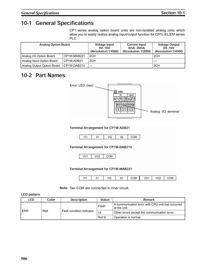
General Specifications
CP1 series analog option board units are non-isolated analog units which
allow you to easily realize analog input/output function for CP1L-EL/EM series
PLC.
Two COM are connected in inner circuit.
Analog I/O Option Board CP1W-MAB221 2CH 2CH
Analog Input Option Board CP1W-ADB21 2CH ---
Analog Output Option Board CP1W-DAB21V --- 2CH
Analog I/O terminal
Error LED (red)
II1 VI2 COMII2 COM
VO1 VO2 COM
VI1 II1 VI2 II2 COM
VO2VO1VI1
ERR Red Fault condition indicator
FlashA communication error with CPU unit has occurred at the unit.
Lit Other errors except the communication error.
Not lit Operation is normal.

507
Installation and Setting
The following processing explains how to install and remove an Analog Option
Board.
Always turn OFF the power supply to the CPU unit and wait until all the oper-
ation indicators go out before installing or removing the analog option board.
Not doing so may result in an unexpected operation.
1,2,3... 1. Press the up/down lock-levers on both sides of the Option Board slot cover
at the same time to unlock the cover, and then pull the cover out.
2. Check the alignment to make the corner cut of the Analog Option Board fit
in the Option Board slot, and firmly press the Analog Option Board in until
it snaps into place.
To use the analog option board on CP1L-EL/EM series PLC, firstly, it is neces-
sary to set the serial communication settings of the CPU Unit in one of the fol-
lowing two ways.
Set by Dipswitch on PLC unit.
For CPU Units with 30 and 40 points, switch DipSW4 of the CPU unit to ON, if
the Analog Option Board is mounted on the Option Board slot 1 (left side).
Switch DipSW5 of the CPU unit to ON, if the Analog Option Board is mounted
on the Option Board slot 2 (right side).
For CPU Units with 20 I/O points, switch DipSW4 of the CPU unit to ON.
DipSW4 and DipSW5 are OFF at shipment.
Set the option port communication parameters by PLC settings.
If DipSW4 or DipSW5 is OFF, the relative option port's communication param-
eters can also be set by PLC settings in CX-Programmer.
Please set the baud rate of the relative option port at 115200bps in Toolbus
mode.
Always turn OFF the power supply to the CPU unit and wait until all the oper-
ation indicators go out.
Press the up/down lock-levers on both sides of the Analog Option Board at
the same time to unlock the Option Board, and then pull it out.
00NC 02 04 06 08 10 00 02 04 06 08 10
01COM 03 05 07 09 11 01 03 05 07 09 11
00 01 02 03 04 06 00 01 03 04 06
COM 02 COM 05 07COMCOM(V+) 05 07
ON
1 2 3 4 5 6
DipSW4 DipSW5
508
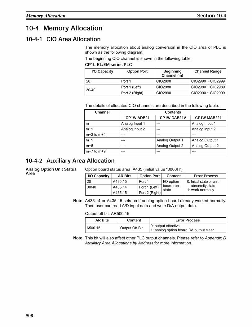
Memory Allocation
The memory allocation about analog conversion in the CIO area of PLC is
shown as the following diagram.
The beginning CIO channel is shown in the following table.
The details of allocated CIO channels are described in the following table.
Option board status area: A435 (initial value “0000H”)
A435.14 or A435.15 sets on if analog option board already worked normally.
Then user can read A/D input data and write D/A output data.
Output off bit: AR500.15
This bit will also affect other PLC output channels. Please refer to Appendix D
Auxiliary Area Allocations by Address for more information.
20 Port 1 CIO2990 CIO2990 ~ CIO2999
30/40Port 1 (Left) CIO2980 CIO2980 ~ CIO2989
Port 2 (Right) CIO2990 CIO2990 ~ CIO2999
m Analog Input 1 --- Analog Input 1
m+1 Analog input 2 --- Analog input 2
m+2 to m+4 --- --- ---
m+5 --- Analog Output 1 Analog Output 1
m+6 --- Analog Output 2 Analog Output 2
m+7 to m+9 --- --- ---
20 A435.15 Port 1 I/O option board run state
0: Initial state or unit abnormity state1: work normally
30/40 A435.14 Port 1 (Left)
A435.15 Port 2 (Right)
A500.15 Output Off Bit0: output effective1: analog option board DA output clear

509
Analog Input Option Board
Each CP1W-ADB21 Analog Input Option Board provides two analog inputs.
• The analog input signal ranges are 0 to 10 V (with a resolution 1/4,000)
and 0 to 20 mA (with a resolution 1/2,000).
Analog input data is digitally converted according to the input signal range as
shown below.
When the input exceeds the specified range, the A/D conversion data will be
fixed at either the lower limit or upper limit.
The 0 to 10 V range corresponds to the hexadecimal values 0000 to 0FA0 (0
to 4000). The entire data range is 0000 to 0FFF (0 to 4095).
Input signal range 0 V to 10 V 0 mA to 20 mA
Max. rated input 0 V to 15 V 0 mA to 30 mA
External input impedance 200 k min. Approx. 250
Resolution 1/4000 (full scale) 1/2000 (full scale)
Overall accuracy25°C: ±0.5% (full scale)0 to 55°C: ±1.0% (full scale)
25°C: ±0.6% (full scale)0 to 55°C: ±1.2% (full scale)
A/D conversion data 0000 to 0FA0 hex 0000 to 07D0 hex
Averaging function Not supported
Conversion timeInner sample time 2ms/pointRefresh time > 6ms basing on baud rate and PLC cycle time
Isolation method None
Current consumption 5 VDC: 20 mA max.
Converted Data
Hexadecimal (Decimal)
10V 10.24V
0FA0(4000)
0FFF(4095)
0000(0)
0V

510
Analog Input Option Board
The 0 to 20 mA range corresponds to the hexadecimal values 0000 to 07D0
(0 to 2000). The possible data range is 0000 to 0FFF (0 to 4095). But it is
strongly suggested that the input current must not exceed 30 mA.
When using current inputs, voltage input terminals must be short-circuited
with current input terminals.
Converted Data
Hexadecimal (Decimal)
0mA 20mA
07D0(2000)
0000(0)
VI1 Voltage Input 1
Current Input 1
Voltage Input 2
Current Input 2
II1
VI2
II2
COM Input Common
Analog input 2
Analog ground
I I 1
V I 1
COM ( )
I I 2
V I 2
56 k 250
250
180 k
180 k
Internal circuits Analog input 1
toto
56 k

511
Analog Input Option Board
Solid wire or ferrules can be used.
• Recommended solid wire
• Recommended ferrules
Do not connect bare stranded wires directly to terminals.
When wiring the analog I/O terminal block, treat either solid or stranded wires
directly.
• To make the connection, press the release button in with a small flat blade
screwdriver and push the line in while the lock is released. Remove the
screwdriver and lock it inside.
• To disconnect the wiring, press the release button in with a small flat
blade screwdriver and pull the line out while the lock is released.
(1) Ferrules with/without plastic sleeve cannot be used.
(2) When using stranded wire, twist the core so that the barbed wires cannot
protrude.
(3) Do not solder-plate the end of cable.
The screwdriver shown below is recommended for wiring.
Wire type Wire size
Solid Wire 0.2mm2 to 0.5mm2 (AWG24 to AWG20)
Manufacturer Model Applicable wire
Phoenix Contact AI-0.5-10 0.5mm2 (AWG20)
Release button
2-conductor shielded twisted-pair cable
Model Manufacturer
SZS 0.4 2.5 Phoenix Contact
0.4mm
Side Front
2.5mm

512
Analog Output Option Board
To prevent noise, 2-core shielded twisted-pair cable should be used. And the
shield can be connected to the FG terminal if necessary.
(1) If necessary, connect the shield to the FG terminal to prevent noise.
(2) When an input is not being used, short the + and – terminals.
(3) Separate wiring from power lines (AC power supply lines, high-voltage
lines, etc.)
(4) When there is noise in the power supply line, install a noise filter on the
input section and the power supply.
When connecting the analog option board to an outside analog device, either
ground the 0 V side of the PLC’s external power supply or do not ground the
PLC’s external power supply at all. Otherwise the PLC’s external power sup-
ply may be shorted depending on the connection methods of the outside ana-
log device. DO NOT ground the 24 V side of the PLC's external power supply,
as shown in the following diagram.
Each CP1W-DAB21V Analog Output Option Board provides two analog outputs.
• The analog output signal range is 0 to 10 V (with a resolution 1/4,000).
V IN
COM
I IN
V IN
COM
I IN
Analog device with voltage output
Analog Input Option Board
Analog
device with
current
output
Analog Input Option Board
2-core shieldedtwisted-pair cable
2-core shieldedtwisted-pair cable
FG FG
24 V
0 V 0 V
Non-insulated DC power supply
0 V
Analog Device FG FG FG
Twisted-pair
cable
FG
CPU Unit + Analog Option Board
Output signal range 0 V to 10 V ---
External output allowable load resistance 2 k min. ---
External output impedance 0.5 max. ---
Resolution 1/4,000 (full scale) ---
Overall accuracy 25°C: ±0.5% 0 to 55°C: ±1.0% ---
D/A conversion data 0000 to 0FA0 hex ---
Conversion timeInner conversion time 2ms/pointRefresh time > 6ms basing on baud rate and PLC cycle time
Isolation method None
Current consumption 5 VDC: 60 mA max.

513
Analog Output Option Board
The analog values depend on the output signal range, as shown in the follow-
ing diagram.
When the output exceeds the specified range, the output signal will be fixed at
either the lower limit or upper limit.
The hexadecimal values 0000 to 0FA0 (0 to 4000) correspond to an analog
voltage range of 0 to 10 V. The entire output range is 10 to 10.24 V.
0V
10V
0FA0
FFFF
0FFF
(4000) (4095)
0000(0)Converted Data Hexadecimal
(Decimal)
10.24V
VO1 Voltage Output 1
VO2 Voltage Output 2
COM Output Common
Analog output 1
Analog ground
V O 1
COM( )
V O 2
Analog output 2
toto
Internal circuits
514
Analog Output Option Board
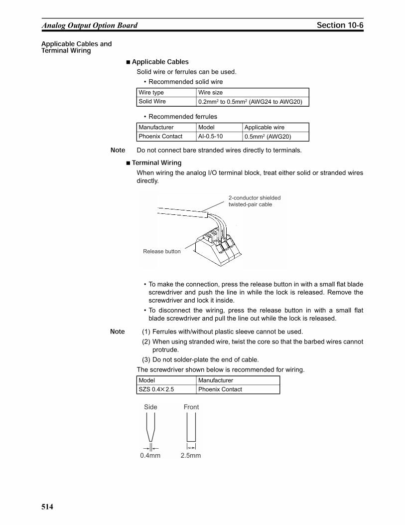
Solid wire or ferrules can be used.
• Recommended solid wire
• Recommended ferrules
Do not connect bare stranded wires directly to terminals.
When wiring the analog I/O terminal block, treat either solid or stranded wires
directly.
• To make the connection, press the release button in with a small flat blade
screwdriver and push the line in while the lock is released. Remove the
screwdriver and lock it inside.
• To disconnect the wiring, press the release button in with a small flat
blade screwdriver and pull the line out while the lock is released.
(1) Ferrules with/without plastic sleeve cannot be used.
(2) When using stranded wire, twist the core so that the barbed wires cannot
protrude.
(3) Do not solder-plate the end of cable.
The screwdriver shown below is recommended for wiring.
Wire type Wire size
Solid Wire 0.2mm2 to 0.5mm2 (AWG24 to AWG20)
Manufacturer Model Applicable wire
Phoenix Contact AI-0.5-10 0.5mm2 (AWG20)
Release button
2-conductor shielded twisted-pair cable
Model Manufacturer
SZS 0.4 2.5 Phoenix Contact
0.4mm
Side Front
2.5mm
515
Analog Output Option Board
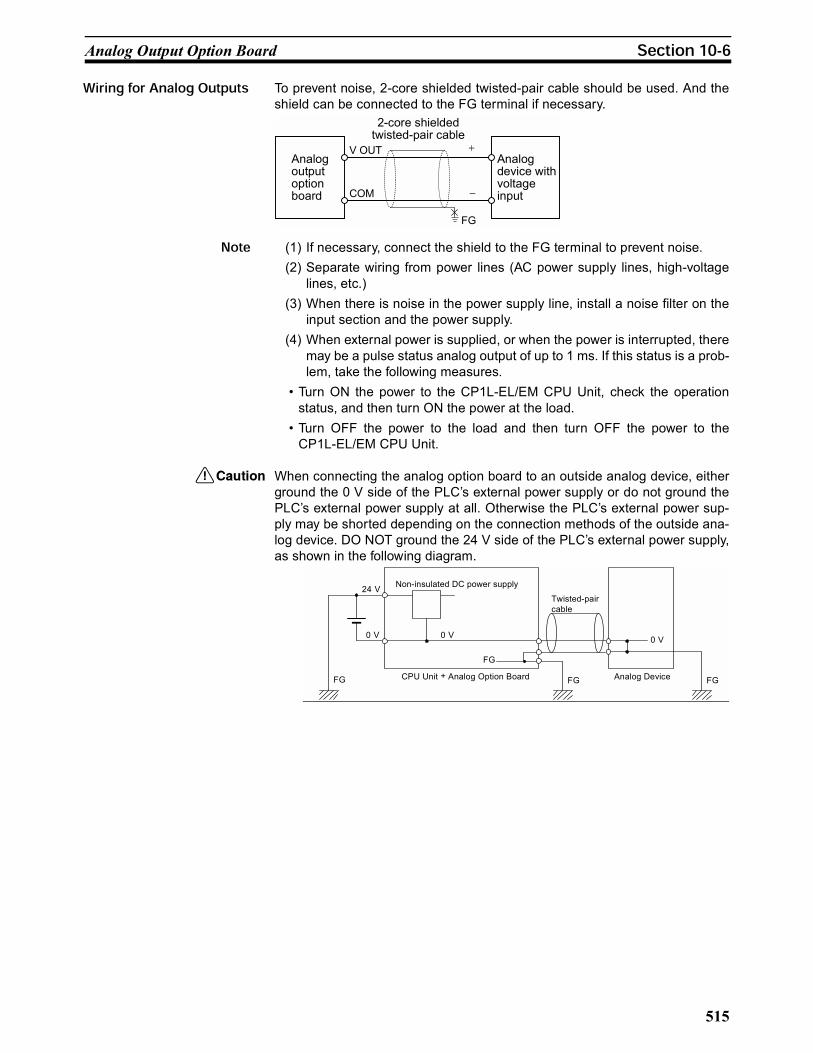
To prevent noise, 2-core shielded twisted-pair cable should be used. And the
shield can be connected to the FG terminal if necessary.
(1) If necessary, connect the shield to the FG terminal to prevent noise.
(2) Separate wiring from power lines (AC power supply lines, high-voltage
lines, etc.)
(3) When there is noise in the power supply line, install a noise filter on the
input section and the power supply.
(4) When external power is supplied, or when the power is interrupted, there
may be a pulse status analog output of up to 1 ms. If this status is a prob-
lem, take the following measures.
• Turn ON the power to the CP1L-EL/EM CPU Unit, check the operation
status, and then turn ON the power at the load.
• Turn OFF the power to the load and then turn OFF the power to the
CP1L-EL/EM CPU Unit.
When connecting the analog option board to an outside analog device, either
ground the 0 V side of the PLC’s external power supply or do not ground the
PLC’s external power supply at all. Otherwise the PLC’s external power sup-
ply may be shorted depending on the connection methods of the outside ana-
log device. DO NOT ground the 24 V side of the PLC’s external power supply,
as shown in the following diagram.
COM
V OUTAnalog output option board
Analog device with voltage input
FG
2-core shieldedtwisted-pair cable
24 V
0 V 0 V
Non-insulated DC power supply
0 V
Analog Device FG FG FG
Twisted-pair
cable
FG
CPU Unit + Analog Option Board
516
Analog I/O Option Board
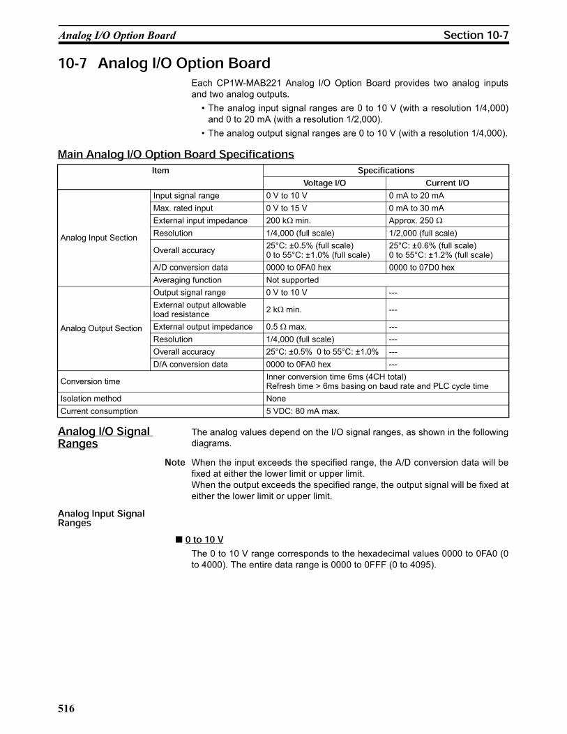
Each CP1W-MAB221 Analog I/O Option Board provides two analog inputs
and two analog outputs.
• The analog input signal ranges are 0 to 10 V (with a resolution 1/4,000)
and 0 to 20 mA (with a resolution 1/2,000).
• The analog output signal ranges are 0 to 10 V (with a resolution 1/4,000).
The analog values depend on the I/O signal ranges, as shown in the following
diagrams.
When the input exceeds the specified range, the A/D conversion data will be
fixed at either the lower limit or upper limit.
When the output exceeds the specified range, the output signal will be fixed at
either the lower limit or upper limit.
The 0 to 10 V range corresponds to the hexadecimal values 0000 to 0FA0 (0
to 4000). The entire data range is 0000 to 0FFF (0 to 4095).
Analog Input Section
Input signal range 0 V to 10 V 0 mA to 20 mA
Max. rated input 0 V to 15 V 0 mA to 30 mA
External input impedance 200 k min. Approx. 250
Resolution 1/4,000 (full scale) 1/2,000 (full scale)
Overall accuracy25°C: ±0.5% (full scale)0 to 55°C: ±1.0% (full scale)
25°C: ±0.6% (full scale)0 to 55°C: ±1.2% (full scale)
A/D conversion data 0000 to 0FA0 hex 0000 to 07D0 hex
Averaging function Not supported
Analog Output Section
Output signal range 0 V to 10 V ---
External output allowable load resistance
2 k min. ---
External output impedance 0.5 max. ---
Resolution 1/4,000 (full scale) ---
Overall accuracy 25°C: ±0.5% 0 to 55°C: ±1.0% ---
D/A conversion data 0000 to 0FA0 hex ---
Conversion timeInner conversion time 6ms (4CH total)Refresh time > 6ms basing on baud rate and PLC cycle time
Isolation method None
Current consumption 5 VDC: 80 mA max.

517
Analog I/O Option Board
The 0 to 20 mA range corresponds to the hexadecimal values 0000 to 07D0
(0 to 2000). The possible data range is 0000 to 0FFF (0 to 4095). But it is
strongly suggested that the input current mustn’t exceed 30 mA.
The hexadecimal values 0000 to 0FA0 (0 to 4000) correspond to an analog
voltage range of 0 to 10 V. The entire output range is 10 to 10.24 V.
Converted Data
Hexadecimal (Decimal)
10V 10.24V
0FA0(4000)
0FFF(4095)
0000(0)
0V
Converted Data
Hexadecimal (Decimal)
0mA 20mA
07D0(2000)
0000(0)
0V
10V
0FA0
FFFF
0FFF
(4000) (4095)
0000(0)Converted Data Hexadecimal
(Decimal)
10.24V
518
Analog I/O Option Board
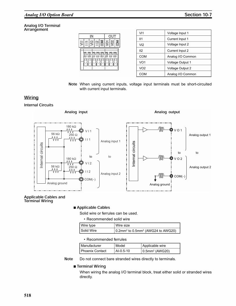
When using current inputs, voltage input terminals must be short-circuited
with current input terminals.
Solid wire or ferrules can be used.
• Recommended solid wire
• Recommended ferrules
Do not connect bare stranded wires directly to terminals.
When wiring the analog I/O terminal block, treat either solid or stranded wires
directly.
VI1 Voltage Input 1
II1 Current Input 1
VI2 Voltage Input 2
II2 Current Input 2
COM Analog I/O Common
VO1 Voltage Output 1
VO2 Voltage Output 2
COM Analog I/O Common
Analog input 2
Analog ground
I I 1
V I 1
COM( )
I I 2
V I 2
56 k 250
250
180 k
180 k
Internal circuits
Analog input 1
to
56 k
Analog output 1
Analog ground
V O 1
COM( )
V O 2
Analog output 2
toto
to
Internal circuits
Wire type Wire size
Solid Wire 0.2mm2 to 0.5mm2 (AWG24 to AWG20)
Manufacturer Model Applicable wire
Phoenix Contact AI-0.5-10 0.5mm2 (AWG20)

519
Analog I/O Option Board
• To make the connection, press the release button in with a small flat blade
screwdriver and push the line in while the lock is released. Remove the
screwdriver and lock it inside.
• To disconnect the wiring, press the release button in with a small flat
blade screwdriver and pull the line out while the lock is released.
(1) Ferrules with/without plastic sleeve cannot be used.
(2) When using stranded wire, twist the core so that the barbed wires cannot
protrude.
(3) Do not solder-plate the end of cable.
The screwdriver shown below is recommended for wiring.
To prevent noise, 2-core shielded twisted-pair cable should be used. And the
shield can be connected to the FG terminal if necesssary.
Release button
2-conductor shielded twisted-pair cable
Model Manufacturer
SZS 0.4 2.5 Phoenix Contact
0.4mm
Side Front
2.5mm
V IN
COM
I IN
V IN
COM
I IN
Analog device with voltage output
Analog I/O Option Board
Analog
device with
current
output
Analog I/O Option Board
2-core shieldedtwisted-pair cable
2-core shieldedtwisted-pair cable
FG FG

520
Startup Operation
(1) If necessary, connect the shield to the FG terminal to prevent noise.
(2) When an input is not being used, short the + and – terminals.
(3) Separate wiring from power lines (AC power supply lines, high-voltage
lines, etc.)
(4) When there is noise in the power supply line, install a noise filter on the
input section and the power supply.
(5) When external power is supplied, or when the power is interrupted, there
may be a pulse status analog output of up to 1 ms. If this status is a prob-
lem, take the following measures.
• Turn ON the power to the CP1L-EL/EM CPU Unit, check the operation
status, and then turn ON the power at the load.
• Turn OFF the power to the load and then turn OFF the power to the
CP1L-EL/EM CPU Unit.
When connecting the analog option board to an outside analog device, either
ground the 0 V side of the PLC’s external power supply or do not ground the
PLC’s external power supply at all. Otherwise the PLC’s external power sup-
ply may be shorted depending on the connection methods of the outside ana-
log device. DO NOT ground the 24 V side of the PLC’s external power supply,
as shown in the following diagram.
After the power is turned ON, analog option board starts the initialization pro-
cess. If the initialization finishes normally, the initialization completed flag in
related status area (Refer to : A435) will be
set. Therefore, status monitor content must be added in ladder. Only when the
initialization process has finished, user can use the A/D conversion data or
write the output data.
The analog input data will be 0000 until the initial processing is completed.
COM
V OUTAnalog I/O Option Board
Analog device with voltage input
FG
2-core shieldedtwisted-pair cable
24 V
0 V 0 V
Non-insulated DC power supply
0 V
Analog Device FG FG FG
Twisted-pair
cable
FG
CPU Unit + Analog Option Board

521
Trouble Shooting
Mount the analog option board into the option port.
Connect to the analog input/output device.
Two methods:
1. DipSW4/DipSW5 set ON: TOOLBUS auto-detect
2. DipSW4/DipSW5 set OFF: Set communication protocol in PLC settings to
TOOLBUS, 115200bps
Wait until the analog option board finishes initialization and works normally.
Read the analog input data/write the analog output data.
(1) If PLC communication protocol setting is error, the option board will al-
ways try to link the PLC, and the error LED will flash.
(2) Only when the initialization process has finished (AR435.14/15 sets on),
user can use the A/D conversion data or write the D/A output data.
Lit CPU Unit service monitoring error
Service from the CPU Unit was not completed within the fixed interval.
Check and cor-rect the CPU Unit's operating environment. Check serial communication setting.
A435.14 or A435.15 will be OFF
AD/DA conversion will stop. The analog input conversion data stops refreshing and the analog output conversion output becomes 0V.
Option board error
An error occurred in the Analog Option Board.
Restart the CPU Unit. Replace the Analog Option Board if the error recurs.
Flashing Communication error
The communica-tion between PLC is out of ser-vice
Check if PLC is running normally.
A435.14 or A435.15 will be OFF
AD/DA conversion will stop. The analog input conversion data stops refreshing and the analog output conversion output becomes 0V. If the communica-tion recovers from error, the AD/DA conversion will start again.
Connection with the analog
input/output device
Make the ladder program
Mount the analog option
board
Communication protocol
setting
AD/DA convert

522
The Use of Analog Option Board
Use the analog option board to carry out 2CH AD inputs and 1CH DA output
at the same time.
The ranges of AD/DA are as follows:
Analog input1: 0~10V
Analog input2: 0~20mA
Analog output1: 0~10V
System composing: CP1L-EM (option port 1) + CP1W-MAB221
2980
D0
MOV(021)
2981
D1
MOV(021)
D2
2985
MOV(021)
Execution condition
Execution condition
Execution condition
Reads analog input 1's converted value to D0.
Reads analog input 2's converted value to D1.
The content of D2 is written to the analog output 1.
A435.14
A435.14
A435.14
A435.14 sets on if the analog option board (mounted in option port 1) works normally.