
Section 1 Overhead Sign Structure Types - Caltrans · 1 - 2 . Section 1 - Overhead Sign Structure...
21
1 - 1 Overhead Sign Structures Section 1 Overhead Sign Structure Types A variety of overhead sign structures have been designed and can be called out for use in a construc- tion contract. The majority of the overhead sign structures fit into one of five categories: • Truss • Tubular • Box Beam Closed Truss • Bridge Mounted • Lightweight The Standard Plans provide specific sheets detailing the structural components and connections of each type of overhead sign structure. The project plans may also contain sheets that supplement or override details in the Standard Plans, as applicable to each contract. On occasion, a non-standard overhead sign structure is specified in a contract that does not fit into any of the five categories previously mentioned above. The non-standard sign structures are designed to accommodate certain site conditions or aesthetic concerns. Refer to Photo 1.1. The Standard Plans may be referenced for portions of the structural details of non-standard overhead sign structures, but the project plans will contain the majority of details for the fabrication of the structures. January 2003 DIVISION OF ENGINEERING SERVICES DIVISION OF ENGINEERING SERVICES DIVISION OF ENGINEERING SERVICES DIVISION OF ENGINEERING SERVICES DIVISION OF ENGINEERING SERVICES
Transcript of Section 1 Overhead Sign Structure Types - Caltrans · 1 - 2 . Section 1 - Overhead Sign Structure...
1 - 1 Overhead Sign Structures
Section 1 Overhead Sign Structure Types
A variety of overhead sign structures have been designed and can be called out for use in a construc-tion contract. The majority of the overhead sign structures fit into one of five categories:
• Truss • Tubular • Box Beam Closed Truss • Bridge Mounted • Lightweight
The Standard Plans provide specific sheets detailing the structural components and connections of each type of overhead sign structure. The project plans may also contain sheets that supplement or override details in the Standard Plans, as applicable to each contract.
On occasion, a non-standard overhead sign structure is specified in a contract that does not fit into any of the five categories previously mentioned above. The non-standard sign structures are designed to accommodate certain site conditions or aesthetic concerns. Refer to Photo 1.1. The Standard Plans may be referenced for portions of the structural details of non-standard overhead sign structures, but the project plans will contain the majority of details for the fabrication of the structures.
January 2003 DIVISION OF ENGINEERING SERVICESDIVISION OF ENGINEERING SERVICESDIVISION OF ENGINEERING SERVICESDIVISION OF ENGINEERING SERVICESDIVISION OF ENGINEERING SERVICES

1 - 2 Section 1 - Overhead Sign Structure Types
Photo 1.1 A non-standard sign structure in District 4.
1-1 Truss Overhead Sign Structures The truss is the most common overhead sign structure in use and the most complicated type. The structure is detailed on sheets S1 through S13 of the Standard Plans. The truss, which can be desig-nated as a one-post type or a two-post type, is composed of multiple steel members welded together. Refer to Figures 1-1.1 through 1-1.3. Each truss has four chord angles that act as the overall frame of the truss. These members contribute to the overall bending resistance in the truss by providing tension-compression couples.
Welded to the truss are vertical and diagonal angles. These members act together to transfer vertical loads and shear throughout the truss. Vertical angles tend to be in compression while diagonal angles tend to be in tension. However, due to the layout of these members as well as the lateral loads applied to them, it is not uncommon for vertical angles to be in tension or diagonal angles to be in compression.
Attached to the top and bottom chord angles of the truss are horizontally oriented angles called wind bracing. Refer to Photo 1-1.4. Typical wind bracing runs at an angle away from the chord angle and helps transfer horizontal loads and shear throughout the truss. Additionally, both the one-post and two-post type sign structures have components of wind bracing that run normal to the chord angles. A
January 2003

1 - 3 Overhead Sign Structures
Photo 1-1.1 A two-post truss overhead sign structure.
two-post truss type is detailed with these normal members, re-ferred to as struts, between each wind brace and at the end of any cantilevered section of the truss. For a one-post type truss, these members are called end ties and are located at the ends of the truss and adjacent to the post.
Connected to each pair of ver-tical and diagonal angles (a pair being comprised of a front and back angle both lying on a plane normal to the axis of the truss) is a horizontal angle referred to as a cross tie. In addition to these cross ties, two more angles called internal diagonals
Photo 1-1.2 Back side of a two-post truss overhead sign structure.
Photo 1-1.3 Back of a one-post truss overhead sign structure.
January 2003 DIVISION OF ENGINEERING SERVICESDIVISION OF ENGINEERING SERVICESDIVISION OF ENGINEERING SERVICESDIVISION OF ENGINEERING SERVICESDIVISION OF ENGINEERING SERVICES
1 - 4 Section 1 - Overhead Sign Structure Types
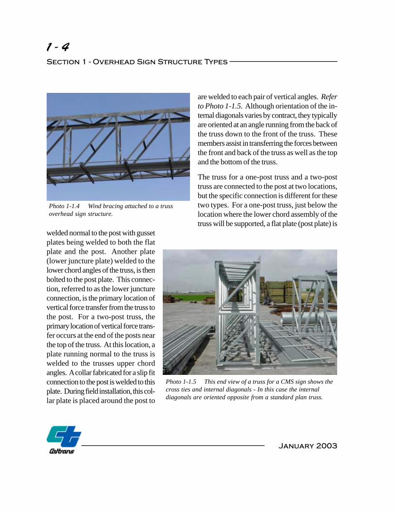
Photo 1-1.4 Wind bracing attached to a truss overhead sign structure.
are welded to each pair of vertical angles. Refer to Photo 1-1.5. Although orientation of the in-ternal diagonals varies by contract, they typically are oriented at an angle running from the back of the truss down to the front of the truss. These members assist in transferring the forces between the front and back of the truss as well as the top and the bottom of the truss.
The truss for a one-post truss and a two-post truss are connected to the post at two locations, but the specific connection is different for these two types. For a one-post truss, just below the location where the lower chord assembly of the truss will be supported, a flat plate (post plate) is
welded normal to the post with gusset plates being welded to both the flat plate and the post. Another plate (lower juncture plate) welded to the lower chord angles of the truss, is then bolted to the post plate. This connec-tion, referred to as the lower juncture connection, is the primary location of vertical force transfer from the truss to the post. For a two-post truss, the primary location of vertical force trans-fer occurs at the end of the posts near the top of the truss. At this location, a plate running normal to the truss is welded to the trusses upper chord angles. A collar fabricated for a slip fit connection to the post is welded to this plate. During field installation, this col-lar plate is placed around the post to
Photo 1-1.5 This end view of a truss for a CMS sign shows the cross ties and internal diagonals - In this case the internal diagonals are oriented opposite from a standard plan truss.
January 2003
1 - 5 Overhead Sign Structures
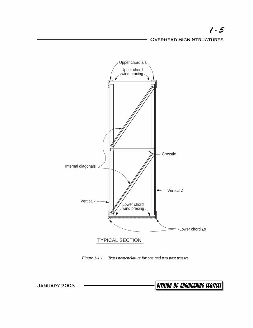
Upper chord s
Upper chord wind bracing
Crosstie
Internal diagonals
Lower chord wind bracing
Vertical
Vertical
Lower chord s
TYPICAL SECTION
Figure 1-1.1 Truss nomenclature for one and two post trusses
January 2003 DIVISION OF ENGINEERING SERVICESDIVISION OF ENGINEERING SERVICESDIVISION OF ENGINEERING SERVICESDIVISION OF ENGINEERING SERVICESDIVISION OF ENGINEERING SERVICES
Ch
ord
an
gle
s (
up
pe
r)
Up
pe
r ju
nctu
reF
ram
e le
ng
th
Le
ft a
rm le
ng
th
Rig
ht
arm
len
gth
Po
st
En
d b
ay
En
d b
ay
Wa
lkw
ay b
racke
t Cro
sstie
s
Dia
go
na
ls
Ve
rtic
als
Ch
ord
an
gle
s (
low
er)
Frame depth L
ow
er
jun
ctu
re
ELE
VA
TIO
N
Win
d b
raci
ng
Wa
lkw
ay
bra
cke
t
Fra
me
wid
th
En
d t
ies
Po
st
Ch
ord
an
gle
s
TY
PIC
AL S
EC
TIO
N L
OO
KIN
G D
OW
N
1 - 6 Section 1 - Overhead Sign Structure Types
January 2003
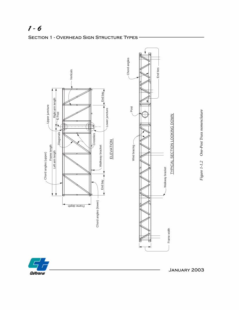
Figu
re 1
-1.2
O
ne-P
ost T
russ
nom
encl
atur
e
1 - 7 Overhead Sign Structures
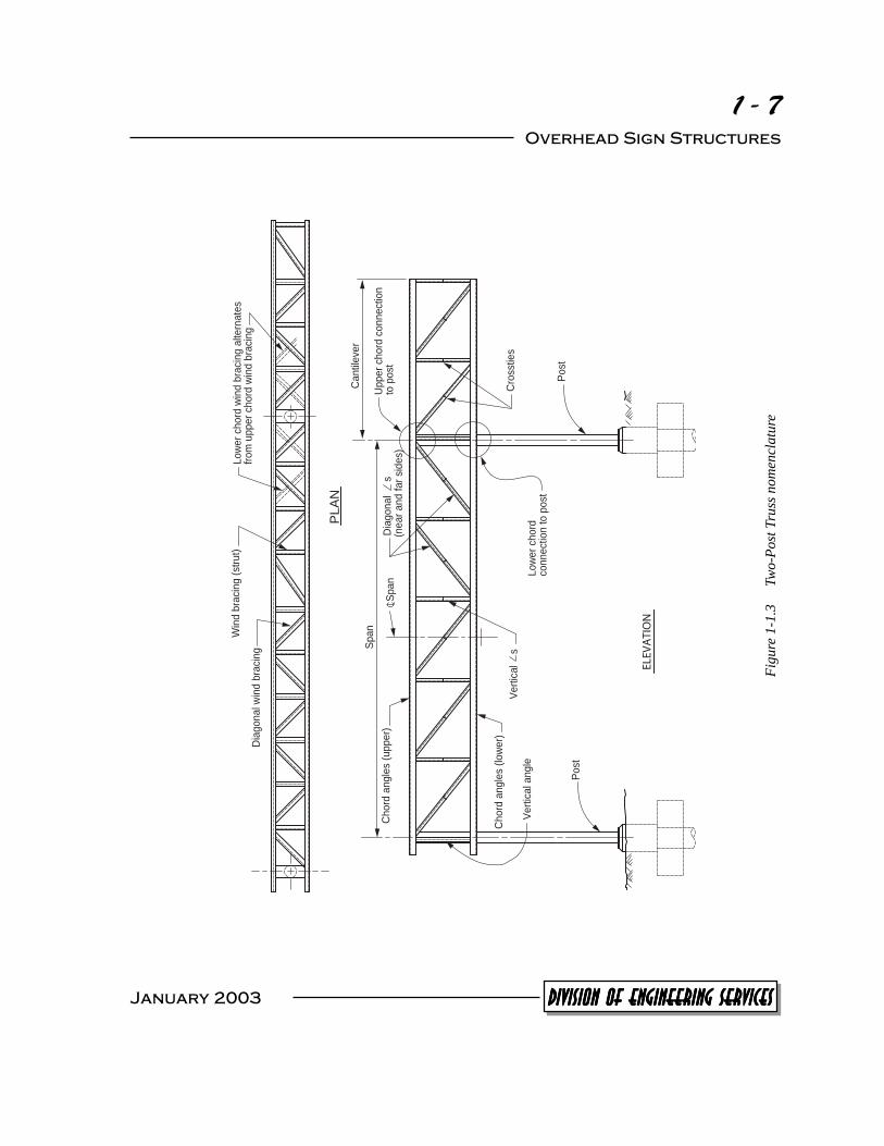
Figu
re 1
-1.3
Tw
o-Po
st T
russ
nom
encl
atur
e
Win
d b
raci
ng (
stru
t)
Post
Post
Up
pe
r ch
ord
co
nn
ect
ion
to p
ost
Lo
we
r ch
ord
connect
ion to p
ost
Lo
we
r ch
ord
win
d b
raci
ng
alte
rna
tes
from
upper
chord
win
d b
raci
ng
Vert
ical
s
Dia
go
na
l s
Sp
an
Sp
an
ELEV
ATI
ON
Cro
sstie
s
(near
and f
ar
sides)
PL
AN
Ve
rtic
al a
ng
le
Dia
go
na
l win
d b
raci
ng
Ch
ord
an
gle
s (lo
we
r)
Ch
ord
an
gle
s (u
pp
er)
Ca
ntil
eve
r
January 2003 DIVISION OF ENGINEERING SERVICESDIVISION OF ENGINEERING SERVICESDIVISION OF ENGINEERING SERVICESDIVISION OF ENGINEERING SERVICESDIVISION OF ENGINEERING SERVICES

1 - 8 Section 1 - Overhead Sign Structure Types
TR
US
S
TY
PIC
AL W
ALK
WA
Y S
EC
TIO
N
Figu
re 1
-1.4
W
alkw
ay n
omen
clat
ure
Walk
way
gra
ting
Lig
ht fix
ture
Sa
fety
an
gle
Lo
we
r ch
ord
an
gle
s
Sa
fety
an
gle
L
igh
t fix
ture
Fix
ture
mo
un
ting
ch
an
ne
ls
Safe
ty r
aili
ng
Hin
ge
WA
LK
WA
Y P
LA
N
Safe
ty r
aili
ng
Walk
way g
rating
Wa
lkw
ay
bra
cke
t
Lig
ht fix
ture
mo
un
ting
ch
an
ne
ls
Hin
ge
Wa
lkw
ay
bra
cke
t
++
January 2003
1 - 9 Overhead Sign Structures
constitute the upper chord connection to the post. Details for the upper juncture connection for a one-post truss are similar to those for the two-post truss except that the collar is larger, gusset plates are welded to the collar, and the collar is bolted to the post. The lower chord connection to post for a two-post truss consists of two angles and two plates bolted together. The two angles run normal to and are welded to the truss on both sides of the post. Two plates (clamp plates) are then bolted to these angles such that there is a firm connection between the clamp plates and the post after installa-tion.
When a walkway or sign illumination is required, walkway brackets are bolted to the bottom of a truss superstructure. Four members are generally connected to these brackets: a safety angle, walkway grating, handrail, and channels to be used for installing light fixtures. Refer to Figure 1-1.4. All of these assemblies are typically bolted to the walkway brackets except for the handrail hinge, which is either bolted or welded at the option of the fabricator.
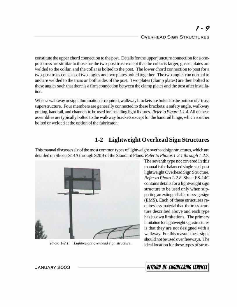
1-2 Lightweight Overhead Sign Structures This manual discusses six of the most common types of lightweight overhead sign structures, which are detailed on Sheets S14Athrough S20B of the Standard Plans. Refer to Photos 1-2.1 through 1-2.7.
The seventh type not covered in this manual is the balanced single steel post lightweight Overhead Sign Structure. Refer to Photo 1-2.8. Sheet ES-14C contains details for a lightweight sign structure to be used only when sup-porting an extinguishable message sign (EMS). Each of these structures re-quires less material than the truss struc-ture described above and each type has its own limitations. The primary limitation for lightweight sign structures is that they are not designed with a walkway. For this reason, these signs should not be used over freeways. The
Photo 1-2.1 Lightweight overhead sign structure. ideal location for these types of struc-
January 2003 DIVISION OF ENGINEERING SERVICESDIVISION OF ENGINEERING SERVICESDIVISION OF ENGINEERING SERVICESDIVISION OF ENGINEERING SERVICESDIVISION OF ENGINEERING SERVICES

1 - 10 Section 1 - Overhead Sign Structure Types
tures are on municipality roads near freeway entrances. These locations should have adequate access for maintenance vehicles, equipment, and personnel.
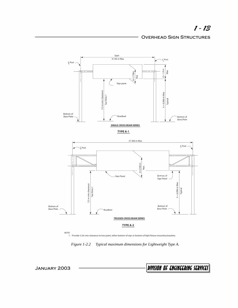
The Type A lightweight overhead sign structure is the only two-post lightweight sign structure. AType A-1 has a single cross beam and is limited to a span of 9.144 meters (30 feet) and a sign panel depth of 1778 mm (70 inches). For a larger sign panel or a span up to 21.336 meters (70 feet), a Type A-2 can
Photo 1-2.3 Lightweight Type A-2.
Photo 1-2.2 This non-standard design is similar to a lightweight Type A-1.
be used, which has been de-signed with a trussed cross beam for additional stiffness. In addition to the above limita-tions, a Type A lightweight structure has not been designed for an ‘h’ value (the distance from the bottom of the base plate to the bottom of the sign panel for lightweight structures) in excess of 6.096 meters (20 feet). Refer to Figure 1-2.2.
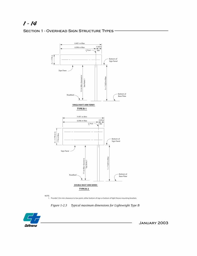
Both the Type B and Type C lightweight sign structures can
be designed for an ‘h’ value up to 7.620 meters (25 feet) but are only of the one-post type. The Type B structure is a butterfly design (sign panel extends on both sides of the post) while the Type C structure is a cantilever design. AType B-1 structure has been designed with a single mast arm and is
January 2003

1 - 11 Overhead Sign Structures
Photo 1-2.5 Lightweight Type B-2.
Photo 1-2.4 Lightweight Type B-1.
Photo 1-2.7 Lightweight Type C-2.
Photo 1-2.6 Lightweight Type C-1.
January 2003 DIVISION OF ENGINEERING SERVICESDIVISION OF ENGINEERING SERVICESDIVISION OF ENGINEERING SERVICESDIVISION OF ENGINEERING SERVICESDIVISION OF ENGINEERING SERVICES
1 - 12 Section 1 - Overhead Sign Structure Types
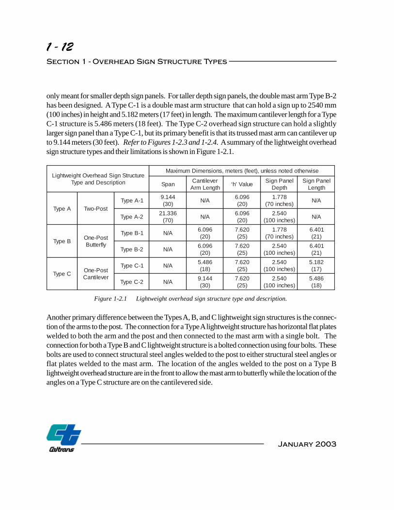
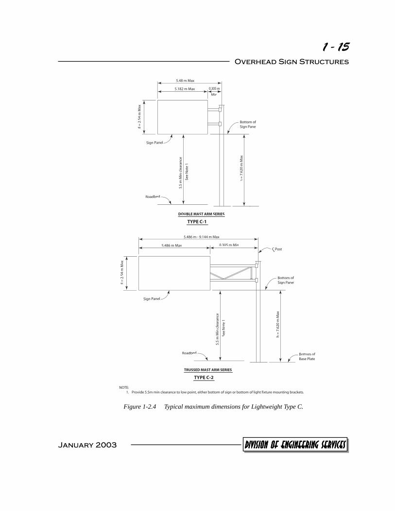
only meant for smaller depth sign panels. For taller depth sign panels, the double mast arm Type B-2 has been designed. AType C-1 is a double mast arm structure that can hold a sign up to 2540 mm (100 inches) in height and 5.182 meters (17 feet) in length. The maximum cantilever length for a Type C-1 structure is 5.486 meters (18 feet). The Type C-2 overhead sign structure can hold a slightly larger sign panel than a Type C-1, but its primary benefit is that its trussed mast arm can cantilever up to 9.144 meters (30 feet). Refer to Figures 1-2.3 and 1-2.4. A summary of the lightweight overhead sign structure types and their limitations is shown in Figure 1-2.1.
Lightweight Overhead Sign Structure Type and Description
Maximum Dimensions, meters (feet), unless noted otherwise
Span Cantilever
Arm Length ‘h’ Value
Sign Panel Depth
Sign Panel Length
Type A Two-Post Type A-1
9.144 (30) N/A
6.096 (20)
1.778 (70 inches) N/A
Type A-2 21.336
(70) N/A 6.096 (20)
2.540 (100 inches) N/A
Type B One-Post Butterfly
Type B-1 N/A 6.096 (20)
7.620 (25)
1.778 (70 inches)
6.401 (21)
Type B-2 N/A 6.096 (20)
7.620 (25)
2.540 (100 inches)
6.401 (21)
Type C One-Post Cantilever
Type C-1 N/A 5.486 (18)
7.620 (25)
2.540 (100 inches)
5.182 (17)
Type C-2 N/A 9.144 (30)
7.620 (25)
2.540 (100 inches)
5.486 (18)
Figure 1-2.1 Lightweight overhead sign structure type and description.
Another primary difference between the Types A, B, and C lightweight sign structures is the connec-tion of the arms to the post. The connection for a Type A lightweight structure has horizontal flat plates welded to both the arm and the post and then connected to the mast arm with a single bolt. The connection for both a Type B and C lightweight structure is a bolted connection using four bolts. These bolts are used to connect structural steel angles welded to the post to either structural steel angles or flat plates welded to the mast arm. The location of the angles welded to the post on a Type B lightweight overhead structure are in the front to allow the mast arm to butterfly while the location of the angles on a Type C structure are on the cantilevered side.
January 2003
1 - 13 Overhead Sign Structures
C Post L CC C Post L CC
Sign panel
Span
Bottom of Base Plate Roadbed Bottom of
Base Plate
Max
Max
See
No
te 1
Typ
ical
9.144 m Max
d =
1.8
m
5.5
m m
in c
lear
ance
h =
6.0
96 m
Max
d=
1.77
8m
SINGLE CROSS BEAM SERIES
TYPE A-1
Bottom of Sign Panel
Max
Typ
ical
Sign Panel
Bottom of Base Plate
See
No
te 1
C Post L CC C Post L CC
Roadbed
Bottom of Base Plate
21.366 m Max d
=2.
540
m
5.5
m m
in c
lear
ance
h =
6.0
96 m
Max
TRUSSED CROSS BEAM SERIES
TYPE A-2
NOTE: 1. Provide 5.5m min clearance to low point, either bottom of sign or bottom of light fixture mounting brackets.
Figure 1-2.2 Typical maximum dimensions for Lightweight Type A.
January 2003 DIVISION OF ENGINEERING SERVICESDIVISION OF ENGINEERING SERVICESDIVISION OF ENGINEERING SERVICESDIVISION OF ENGINEERING SERVICESDIVISION OF ENGINEERING SERVICES
1 - 14 Section 1 - Overhead Sign Structure Types
6.401 m Max
d =
1.7
78 m
d =
1.7
78 m
to
C Post L C MinC
6.096 m Max 0.305m
Bottom of Sign Panel
Sign Panel
5.5
m M
in c
lear
aan
ce
h =
7.6
20 m
Max
See
No
te 1
Bottom ofRoadbed Base Plate
SINGLE MAST ARM SERIES
TYPE B-1
6.401 m Max
2.5
m M
4ax
5.5
m M
in c
lear
ance
C Post MinL
Bottom of
0.305m6.096 m Max
CC
See
No
te 1
Sign Panel
Sign Panel
h =
7.6
20 m
Max
Bottom ofRoadbed Base Plate
DOUBLE MAST ARM SERIES
TYPE B-2
NOTE: 1. Provide 5.5m min clearance to low point, either bottom of sign or bottom of light fixture mounting brackets.
Figure 1-2.3 Typical maximum dimensions for Lightweight Type B
January 2003
1 - 15 Overhead Sign Structures
0.305 m
Sign Panel
Roadbed
d =
2.5
4 m
Max
See
No
te 1
Bottom of Sign Panel
5.48 m Max
5.182 m Max
Min
5.5
m M
in c
lear
ance
h =
7.6
20 m
Max
DOUBLE MAST ARM SERIES
TYPE C-1
Bottom of Base Plate
d =
2.5
4 m
Max
Sign Panel
Roadbed
Bottom of Sign Panel
C Post L CC
See
No
te 1
5.5
m M
in c
lear
ance
h =
7.6
20 m
Max
5.486 m - 9.144 m Max
5.486 m Max 0.305 m Min
TRUSSED MAST ARM SERIES
TYPE C-2
NOTE: 1. Provide 5.5m min clearance to low point, either bottom of sign or bottom of light fixture mounting brackets.
Figure 1-2.4 Typical maximum dimensions for Lightweight Type C.
January 2003 DIVISION OF ENGINEERING SERVICESDIVISION OF ENGINEERING SERVICESDIVISION OF ENGINEERING SERVICESDIVISION OF ENGINEERING SERVICESDIVISION OF ENGINEERING SERVICES

1 - 16 Section 1 - Overhead Sign Structure Types
The specific location for a sign panel often deter-mines which types of lightweight structures are ap-propriate for each contract. The Designer may specify certain signage (such as an arrow) to be placed on a sign panel over a specific location. This design may make certain lightweight sign structure types impossible to use due to their dimensional limi-tations. Wide shoulders, sidewalks, or bike lanes are other common items that inhibit the use of many of these lightweight structure types. Lightweight overhead sign structures are cost effective, but they are not intended for all signage purposes.
1-3 Box Beam Closed Truss Overhead Sign
Structures There are two different designs for the box beam overhead sign structure that may be encountered in the field. The newer closed truss design is detailed on Sheets S39 through S40M in the Standard Plans. The superstructure details for this structure are very simi-lar to those for the truss structure de-scribed in Section 1-1, “Truss Over-head Sign Structures,” except that this
structure has ribbed sheet metal bolted across the front and back end of the truss and cover plates on the ends. This combination of ribbed sheet metal and cover plates completely cover the entire super-structure except for the top and bottom of a box beam closed truss where its internal components are visible. The superstructure for the older version of the box beam sign structure is not similar to that of
Photo 1-2.8 Lightweight balanced single steel post overhead sign structure.
Photo 1-2.9 Type C-2 trussed mast arm plates for the bolted connection at the post and mast arm.
January 2003
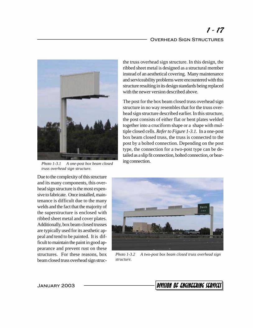
Photo 1-3.1 A one-post box beam closed truss overhead sign structure.
1 - 17 Overhead Sign Structures
the truss overhead sign structure. In this design, the ribbed sheet metal is designed as a structural member instead of an aesthetical covering. Many maintenance and serviceability problems were encountered with this structure resulting in its design standards being replaced with the newer version described above.
The post for the box beam closed truss overhead sign structure in no way resembles that for the truss over-head sign structure described earlier. In this structure, the post consists of either flat or bent plates welded together into a cruciform shape or a shape with mul-tiple closed cells. Refer to Figure 1-3.1. In a one-post box beam closed truss, the truss is connected to the post by a bolted connection. Depending on the post type, the connection for a two-post type can be de-tailed as a slip fit connection, bolted connection, or bear-ing connection.
Due to the complexity of this structure and its many components, this over-head sign structure is the most expen-sive to fabricate. Once installed, main-tenance is difficult due to the many welds and the fact that the majority of the superstructure is enclosed with ribbed sheet metal and cover plates. Additionally, box beam closed trusses are typically used for its aesthetic ap-peal and tend to be painted. It is dif-ficult to maintain the paint in good ap-pearance and prevent rust on these structures. For these reasons, box beam closed truss overhead sign struc-
Photo 1-3.2 A two-post box beam closed truss overhead sign structure.
January 2003 DIVISION OF ENGINEERING SERVICESDIVISION OF ENGINEERING SERVICESDIVISION OF ENGINEERING SERVICESDIVISION OF ENGINEERING SERVICESDIVISION OF ENGINEERING SERVICES

XXXXXXXXXXX
XXXXX
1 - 18 Section 1 - Overhead Sign Structure Types
rad.
Plate
'B'
Optional
P detail L PP C Post L CC
G
Typ exterior corners.
Full penetration
not required.
Axis of sign
108
108
E-3
& E
-4 p
ost
E-1
&
E-2
po
st
108
Varies
Varies Varies
E-1 & E-2 post
E-3 & E-4 post
Typ interior
corners
Plate ''A''
Plate ''B''
Plate ''C''
Plate ''A''
L
108
159 159
719
71
97
14
61
46
159
159
610
10 mm P
, rad.= 25 mm
, rad.= 38 mm
, rad.= 45 mm LPP
L
7 mm PLL
13 mm PLL
8 8
Varies
Flange ''A''
Flange ''A''
Axis of sign
127
254
''B''
x 254 mm
6.35 mm Web plate
Plate 10 mm
5
Cruciform
Multicell Figure 1-3.1 Post cross sections for a box beam closed truss type structure as detailed in
the 1999 Standard Plans.
tures are only designed in very rare situations when requested by a specific district or agency. How-ever, there are currently many box beam closed truss overhead sign structures in operation throughout the State (both the older design and the newer design) as they were more frequently used in the past.
1-4 Tubular Overhead Sign Structures The tubular overhead sign structure consists of multiple segments of Extra Strong and Standard pipe sizes spliced together. Sheets S40N through S40U contain details for both a one-post and two-post type tubular sign structure. Posts for these structures can either be vertical or slanted at an angle off vertical. Each post, whether vertical or slanted, will have a radial bend at the top so that the mast arm is horizontal. Refer to Figures 1-4.1 and 1-4.2. Care needs to be taken by the Contractor such that the member is not damaged and material properties are not altered when forming this bend.1 Other than this radial bend, a tubular overhead sign structure is a fairly simple design with few members.
Standard Specifications Section 56-1.03 “Posts for tubular sign structures shall be formed to the radii shown on the plans...by methods which will not crip or buckle the interior radius of the pipe bend, and which will not change the physical characteristics of the material.”
January 2003
1

L
1 - 19 Overhead Sign Structures
Mast arm ''D
''
Pan
el
dept
h
D/2
D
/2
''h''
(See
For
mat
sht
)
Bottom of base PL
(See Format sheet)
Walkway brackets ''R
'' See
Table
10 Post
Span
Maximum sign panel length
1.83 m
Max
Field
splice
See Note 3
CIDH Pile
''L'' = Sign panel length
SLANTED POST CANTILEVER
NOTES
1. The maximum sign panel overlap onto the post elbow shall not exceed 1.83 m from the field splice.
2. When several sign panels are to be installed with a space between the panels, the space shall be as small as possible and 610 mm maximum.
3. All posts between base plate and field splice are extra strong pipe. All mast arms are standard pipe.
Figure 1-4.1 Diagram from Sheet S40P from the Standard Plans
Span
Bottom of base plate
(see format sheet)
Va
ries
Field splice
Standard pipe
Walkway brackets XS Pipe
Trim bracket between panels
''D''= panel depth
D/2
D/2
C Span = C Optional
field splice
CC L CC
Safety cables
1.83 m
Max
See Note 9
1.8
m
C Post = L CC
C CIDH Pile L CC
''R'' See table
30
5
XS Pipe
(sp
lit le
ng
th)
Bottom of base plate
(see format sheet)
Figure 1-4.2 Diagram from Sheet S40Q from the Standard Plans
January 2003 DIVISION OF ENGINEERING SERVICESDIVISION OF ENGINEERING SERVICESDIVISION OF ENGINEERING SERVICESDIVISION OF ENGINEERING SERVICESDIVISION OF ENGINEERING SERVICES
1 - 20 Section 1 - Overhead Sign Structure Types
1-5 Bridge Mounted Overhead Sign Structures Various types of bridge mounted overhead sign structures have been designed for use when requested by the District Designer. Bridge mounted structures have their own design standard. Except for Stan-dard Plan Sheets S9, S10, and S11 that contain some details for walkway brackets and safety cables that may be connected to a bridge mounted structure, none of these standards have been incorporated into the Standard Plans. Thus, the Designer is required to incorporate detail sheets into the project plans specifying the structural details for bridge mounted overhead sign structure.
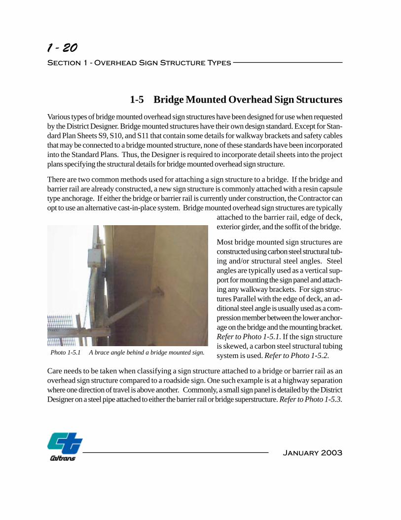
There are two common methods used for attaching a sign structure to a bridge. If the bridge and barrier rail are already constructed, a new sign structure is commonly attached with a resin capsule type anchorage. If either the bridge or barrier rail is currently under construction, the Contractor can opt to use an alternative cast-in-place system. Bridge mounted overhead sign structures are typically
attached to the barrier rail, edge of deck, exterior girder, and the soffit of the bridge.
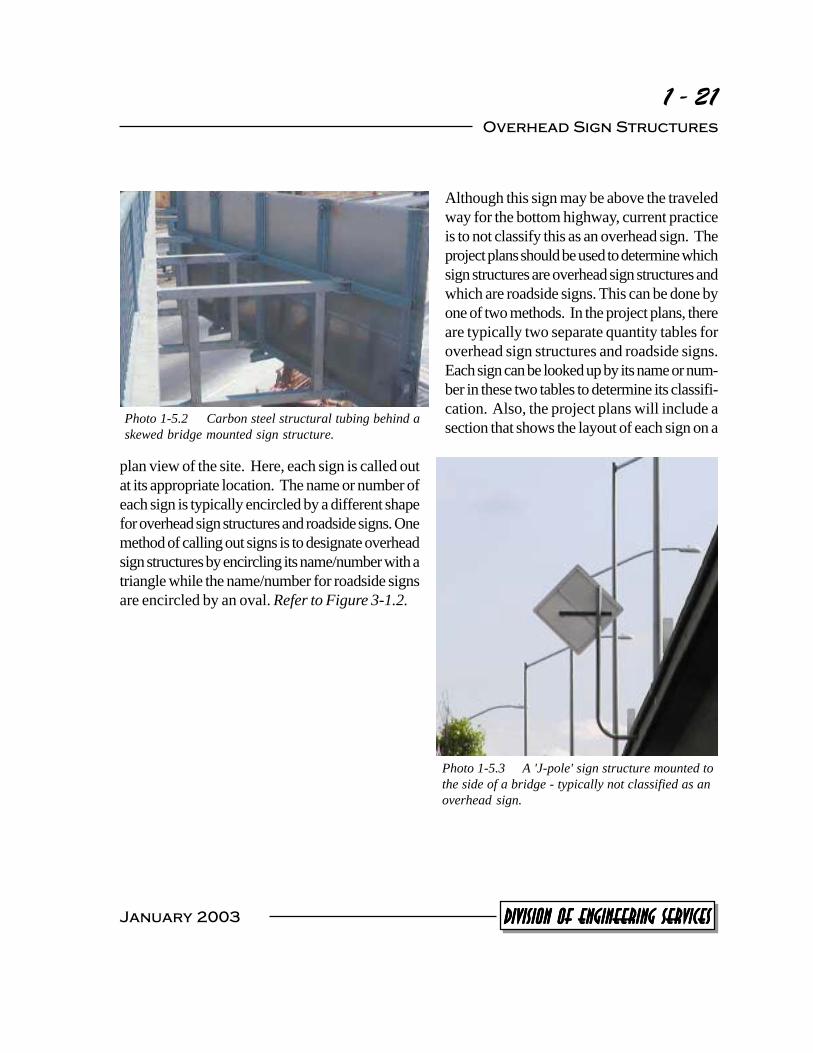
Most bridge mounted sign structures are constructed using carbon steel structural tub-ing and/or structural steel angles. Steel angles are typically used as a vertical sup-port for mounting the sign panel and attach-ing any walkway brackets. For sign struc-tures Parallel with the edge of deck, an ad-ditional steel angle is usually used as a com-pression member between the lower anchor-age on the bridge and the mounting bracket. Refer to Photo 1-5.1. If the sign structure is skewed, a carbon steel structural tubing system is used. Refer to Photo 1-5.2.
Care needs to be taken when classifying a sign structure attached to a bridge or barrier rail as an overhead sign structure compared to a roadside sign. One such example is at a highway separation where one direction of travel is above another. Commonly, a small sign panel is detailed by the District Designer on a steel pipe attached to either the barrier rail or bridge superstructure. Refer to Photo 1-5.3.
Photo 1-5.1 A brace angle behind a bridge mounted sign.
January 2003
1 - 21 Overhead Sign Structures
Photo 1-5.2 Carbon steel structural tubing behind a skewed bridge mounted sign structure.
plan view of the site. Here, each sign is called out at its appropriate location. The name or number of each sign is typically encircled by a different shape for overhead sign structures and roadside signs. One method of calling out signs is to designate overhead sign structures by encircling its name/number with a triangle while the name/number for roadside signs are encircled by an oval. Refer to Figure 3-1.2.
Although this sign may be above the traveled way for the bottom highway, current practice is to not classify this as an overhead sign. The project plans should be used to determine which sign structures are overhead sign structures and which are roadside signs. This can be done by one of two methods. In the project plans, there are typically two separate quantity tables for overhead sign structures and roadside signs. Each sign can be looked up by its name or num-ber in these two tables to determine its classifi-cation. Also, the project plans will include a section that shows the layout of each sign on a
Photo 1-5.3 A 'J-pole' sign structure mounted to the side of a bridge - typically not classified as an overhead sign.
January 2003 DIVISION OF ENGINEERING SERVICESDIVISION OF ENGINEERING SERVICESDIVISION OF ENGINEERING SERVICESDIVISION OF ENGINEERING SERVICESDIVISION OF ENGINEERING SERVICES


![Semantic Structure of the Indian Sign Language [Compatibility Mode]](https://static.fdocuments.in/doc/165x107/62038b30da24ad121e4aa4e1/semantic-structure-of-the-indian-sign-language-compatibility-mode.jpg)


