SECTION 1 DESIGN CRITERIA FOR POTABLE WATER, NON-POTABLE IRRIGATION WATER...
248
TOC.doc 1 of 2 L:\Utilities\UtilitiesProjects\WaterSystemUpgrades\Specs 040312 TABLE OF CONTENTS SECTION 1 DESIGN CRITERIA FOR POTABLE WATER, NON-POTABLE IRRIGATION WATER AND WASTEWATER FACILITIES Part 1 Potable Water and Non-Potable Irrigation Water Systems 1.1 Pipe and Fitting Material 1.2 Design of Pipeline Size and Location 1.2.1 Water Pipeline Sizing Criteria 1.2.2 Distribution System Layout 1.2.3 Pipeline Separation Criteria 1.2.4 Valve Locations 1.3 Conflict Crossings 1.3.1 Subaqueous Canal Crossings 1.4 Fire Service Systems 1.4.1 Fire Service Meters for Residential Systems 1.4.2 Fire Service Meters for Commercial and Non-residential Systems 1.5 Connections to Collier County Facilities 1.6 Water Services 1.6.1 Service Pipelines 1.6.2 Water Meters 1.7 Air Release Assemblies 1.8 Concrete Collars 1.9 Testing and Clearance Procedures 1.9.1 Pigging 1.9.2 Flushing 1.9.3 Line Filling 1.9.4 Chlorination 1.9.5 Post Chlorination Flushes 1.9.6 Bacteriological Samples 1.10 Laboratory Testing and Sample Collection Part 2 Wastewater Collection and Transmission Systems 2.1 Gravity Sewer Systems 2.1.1 Pipe and Fitting Materials 2.1.2 Design of Pipeline Size, Depth and Location 2.1.3 Gravity Sewer Main Extension Stubs 2.1.4 Gravity Sewer Laterals 2.1.5 Manholes 2.2 Force Mains 2.2.1 Pipe and Fitting Materials 2.2.2 Design of Pipeline Size and Location 2.2.3 Valves 2.2.4 Force Main Extension Stubs 2.2.5 Air Release Assemblies 2.3 Pumping Stations 2.4 Connections to Collier County Facilities 2.5 Tests and Inspections EXHIBIT B (Addendum supplemental) 5
Transcript of SECTION 1 DESIGN CRITERIA FOR POTABLE WATER, NON-POTABLE IRRIGATION WATER...

TOC.doc 1 of 2 L:\Utilities\UtilitiesProjects\WaterSystemUpgrades\Specs 040312
TABLE OF CONTENTS SECTION 1 DESIGN CRITERIA FOR POTABLE WATER, NON-POTABLE IRRIGATION
WATER AND WASTEWATER FACILITIES Part 1 Potable Water and Non-Potable Irrigation Water Systems
1.1 Pipe and Fitting Material 1.2 Design of Pipeline Size and Location
1.2.1 Water Pipeline Sizing Criteria 1.2.2 Distribution System Layout 1.2.3 Pipeline Separation Criteria 1.2.4 Valve Locations
1.3 Conflict Crossings 1.3.1 Subaqueous Canal Crossings
1.4 Fire Service Systems 1.4.1 Fire Service Meters for Residential Systems 1.4.2 Fire Service Meters for Commercial and Non-residential Systems 1.5 Connections to Collier County Facilities 1.6 Water Services 1.6.1 Service Pipelines 1.6.2 Water Meters 1.7 Air Release Assemblies 1.8 Concrete Collars 1.9 Testing and Clearance Procedures 1.9.1 Pigging 1.9.2 Flushing 1.9.3 Line Filling 1.9.4 Chlorination 1.9.5 Post Chlorination Flushes 1.9.6 Bacteriological Samples 1.10 Laboratory Testing and Sample Collection Part 2 Wastewater Collection and Transmission Systems 2.1 Gravity Sewer Systems 2.1.1 Pipe and Fitting Materials 2.1.2 Design of Pipeline Size, Depth and Location 2.1.3 Gravity Sewer Main Extension Stubs 2.1.4 Gravity Sewer Laterals 2.1.5 Manholes 2.2 Force Mains 2.2.1 Pipe and Fitting Materials 2.2.2 Design of Pipeline Size and Location 2.2.3 Valves 2.2.4 Force Main Extension Stubs 2.2.5 Air Release Assemblies 2.3 Pumping Stations 2.4 Connections to Collier County Facilities 2.5 Tests and Inspections
EXHIBIT B (Addendum supplemental)
5

TOC.doc 2 of 2 L:\Utilities\UtilitiesProjects\WaterSystemUpgrades\Specs 040312
SECTION 2 TECHNICAL SPECIFICATIONS
DIVISION 1 - GENERAL REQUIREMENTS
01010 Summary of Work 01026 Measurement and Payment 01045 Connections to Existing Systems 01051 Alignment and Grades 01090 References 01400 Quality Control 01500 Construction Facilities and Temporary Controls 01510 Pre-Construction Audio-Video Recording 01570 Traffic Regulation and Public Safety 01600 Material and Equipment 01710 Cleaning 01730 Operation and Maintenance Manuals 01750 Project Record Document
DIVISION 2 - SITEWORK
02050 Demolition 02110 Site Clearing 02151 Shoring, Sheeting and Bracing 02210 Pipe Removal and Abandonment 02222 Excavation – Earth and Rock 02223 Bedding and Backfilling 02226 Jacking, Augering and Mining 02230 Roadway Crossings by Open Cut 02275 NPDES Requirements for Construction Activities Impacting More Than One Acre 02276 Erosion and Sedimentation Control 02400 Restoration by Sodding or Seeding 02523 Sidewalks, Driveways and Curbs 02530 Groundwater Control for Open Cut Excavation 02575 Repair and Restoration of Pavement , Sidewalk, Etc. 02622 Polyvinyl Chloride (PVC) Pipe and Fittings 02630 Ductile Iron Pipe (DIP) and Fittings 02645 Fire Hydrants 02650 Laying and Jointing Buried Pipelines 02675 Disinfection 02676 Pressure and Leakage Tests 02999 Restoration and Miscellaneous Work and Cleanup
DIVISION 15 - MECHANICAL
15100 Water Valves and Appurtenances
EXHIBIT B (Addendum supplemental)
6

SECTION 1
DESIGN CRITERIA FOR POTABLE WATER, NON-POTABLE IRRIGATION WATER, AND
WASTEWATER FACILITIES PART 1 POTABLE WATER AND NON-POTABLE IRRIGATION WATER SYSTEMS All potable water, non-potable irrigation (including reclaimed or reuse) water and raw water pipe, material, equipment and appurtenances shall be new, and shall conform to Section 2, Technical Specifications and Section 3, Utilities Detail Drawings. All material and equipment designed or used in connection with a potable (drinking) water system shall conform to the requirements of the National Sanitation Foundation (NSF) Standard 61, “Drinking Water System Components – Health Effects.” 1.1 Pipe and Fitting Material Potable water and non-potable irrigation water pipelines and fittings, except for service piping, shall be a minimum of six inches (6”) in diameter, and have a minimum depth of thirty-inches (30”) and a maximum depth of forty-eight inches (48”) below finished grade. All potable water or non-potable irrigation water pipelines between six and fourteen inches (6”-14”) in diameter shall be constructed of PVC or HDPE pipe, and shall utilize pipe meeting the requirements of the Technical Specifications. Water pipelines between sixteen inches and twenty-four inches (16”-24”) in diameter may be constructed of ductile iron, HDPE, or PVC pipe. Water pipelines larger than twenty-four inches (24”) in diameter shall be constructed of ductile iron pipe. All pipe and pipe fittings shall contain no more than eight percent (8.0%) lead, and any solder or flux used shall contain no more than two-tenths of a percent (0.2%) lead. All pipe and pipe fittings installed shall be color coded or marked in accordance with F.A.C. 62-555.320(21)(b)3. All HDPE and PVC buried pipelines shall be color-coded as described in the Technical Specifications. Potable water pipelines shall be Federal Safety Blue in color. Raw water pipelines shall be white in color. Non-potable irrigation, reclaimed and reuse water pipelines shall be pantone purple 522C in color. All Ductile Iron, metal and concrete buried water main pipelines shall have blue stripes applied to the pipe wall. Pipes striped during manufacturing of the pipe shall have continuous stripes that run parallel to the axis of the pipe, that are located at no greater than 90 degree intervals around the pipe, and that will remain intact during and after installation of the pipe. If tape or paint is used to stripe pipe during installation, the tape or paint shall be applied in a continuous line that runs parallel to the axis of the pipe and that is located along the top of the pipe.
EXHIBIT B (Addendum supplemental)
7

All buried water pipelines and mains, except those installed by horizontal directional drilling or jack-and-bore methods, shall be marked using plastic locator tape impregnated with metallic filings for HDPE and PVC pipe and non-magnetic for ductile iron pipe. The locator tape shall be placed in the pipe trench two feet (2’) below grade or one-half the pipe’s bury, whichever is less, and labeled “potable water” or “non-potable water” as applicable. Horizontal directional drilling shall include installation of locating tone wire as described in the Technical Specifications. All water main aerial crossings shall be Pressure Class 350 flanged ductile iron pipe and shall be coated on the exterior using a suitable grade of appropriately colored, field applied (or factory applied with field touch-up as required) epoxy coating. Potable water mains shall be painted Federal Safety Blue. Raw water mains shall be painted white. Non-potable irrigation, reclaimed and reuse water mains shall be painted Pantone Purple 522C. Specific colors shall be subject to approval of the CITY Manager or designee. All nuts and bolts used in aerial crossings shall be 316 stainless steel. All canal, river or creek crossings shall be aerial, unless otherwise approved by the CITY Manager or designee. Aerial crossings shall be designed to incorporate valves or other flow regulation devices in accordance with F.A.C. 62-555.320(21)(b). Aerial crossings shall be designed to maintain existing or required navigational capabilities within the waterway and to reserve riparian rights of adjacent property Owners. Submit aerial pipe and flange computations, including support and anchor design, for review. The submittal must be signed and sealed by a Florida registered Professional Engineer. See also Section 02650 3.2.Q for more information. 1.2 Design of Pipeline Size and Location 1.2.1 Water Pipeline Sizing Criteria All water mains to be maintained by the CITY shall be a minimum of six (6) inches in diameter. For dead end mains on short (300' or less) single family residential cul-de-sacs, hydraulic calculations shall show the capability of maintaining 750 gpm fire flow plus potable demand. Water systems shall be designed to maintain adequate flows and pressures and water quality standards as established by Florida Department of Environmental Protection (FDEP), using the following criteria: A. Designs shall assume: 1) a minimum CITY source pressure under peak hourly flow
conditions of 40 PSI, or system available pressure if less than 40 PSI, or developer shall make improvements/water main additions to get adequate pressure delivered from the closest CITY transmission main to the project.; and 2) a minimum CITY source pressure with fire flow under maximum day conditions of 40 PSI, or system available pressure if less than 40 PSI, or developer shall make improvements to get adequate fire flow and pressure delivered from the closest CITY transmission main to the project. Minimum residual node pressure within a proposed project system shall be 20 psi under peak hourly flow and maximum day with fire flow conditions.
B. The design Engineer shall model the proposed system, including all dead ends, for
chlorine dissipation assuming a chloramine residual of 2.0 mg/l at the entrance point to the project.
The following criteria shall be used to analyze model chloramine dissipation unless otherwise approved by the Public Utilities Water Director upon the submittal of specific case data:
EXHIBIT B (Addendum supplemental)
8
a) Occupancy of fifty percent (50%) to account for seasonal variations with the load evenly distributed throughout the project. b) Average occupancy per dwelling of 1.81 for single family and 1.42 for multi-family as established by the Water Master Plan as amended and adjusted for peak with a factor of 1.2 or 2.2 shall be used when modeling system performance. c) Consumption rate of 154 gallons per capita for single family and multi-family shall be used when establishing loading rates for system performance models. d) Systems that are proposed to use or will use alternate irrigation sources shall use fifty percent (50%) of the loading rates for modeling chlorine/chloramine dissipation. e) The standard decay rate is - 0.012 ppm per hour. The analysis assumes a static chlorine level of 2.0 ppm at the tapping point in front of a project. Using the decay rate and solving for the elapsed time from the initial chlorine level to the minimum chlorine level residual of 0.6 ppm in the following: 0.6 ppm = 2.0 ppm x e(-1=0.012 ppm x #hours) => time = 100.33 hours. The Project Engineer shall submit an analysis letter to Community Development and Environmental Services as part of the review package, certifying that all points within the proposed system shall maintain a minimum level of 0.6 mg/l chlorine/chloramine residual under the conditions listed above. Systems unable to meet minimum design requirements or maintain minimum chlorine residual levels shall not be eligible for ownership and maintenance by the CITY. Water mains not designed to carry fire flows shall not have fire hydrants connected to them. 1.2.2 Distribution System Layout Water distribution systems shall be designed so that all systems are located adjacent to, and are accessible from, paved or unpaved roadways so as to allow access for short and long term maintenance, repair and/or replacement of such system. Water mains shall not be placed beneath any existing or proposed building structure. Generally, new potable water distribution systems shall be designed as “looped” systems to avoid dead ends. If changes in design during construction result in dead ends to any new or relocated water mains (except those serving a cul-de-sac), such dead ends shall be connected to the nearest water main. In cases where no nearby water main is available, dead end mains shall not exceed 300 feet in length and shall terminate temporarily in a blow-off, be full-bore flushed, then permanently ended with a hydrant or other flushing device approved by the Engineer of Record in accordance with F.A.C. Chapter 62-555. All commercial facilities must be metered separately from residential facilities with the exception of those commercial facilities that are within a master metered residential development and designed for the exclusive use of the residents within such development. Master meters (for domestic or reuse purposes) and the first gate valve after the master meter (the valve between the meter and the backflow assembly or pressure reducing valve) shall be located within a minimum 15’X15’ CITY Utility Easement (CUE), which shall be located outside of, but contiguous to, the road right-of-way (ROW). Any single residential unit domestic or reuse meter that is not in the ROW shall be located within a minimum 12’X12’ CITY Utility Easement (CUE), which shall be located outside of, but contiguous to, the ROW. For any 3” and larger combination fire and domestic meter assembly and 3” and larger compound meter assembly,
EXHIBIT B (Addendum supplemental)
9

the meter and the valve after the meter (the valve between the meter and the backflow assembly) shall be dedicated to and owned by the CITY, and shall be located within a minimum 15’X15’ City Utility Easement (CUE), which shall be located outside of, but contiguous to, the ROW. Any fire system detector check assembly on a for-fire-only dedicated line shall have an isolation valve at the City water main, plus an isolation valve in the ground just preceding the aboveground detector assembly, and such valves, if not located in the ROW, shall be located within a minimum 15’X15’ City Utility Easement (CUE), which shall be located outside of, but contiguous to, the ROW, and which shall encompass the detector assembly as well; the City shall own up until the valve in the ground preceding the fire system detector check assembly, and the fire detector check assembly shall be owned by the developer. Water mains shall have a minimum setback of seven feet and six inches (7’6”) from the centerline of the pipe to residential roadways, curb and gutters, permanent structures, or planting not specifically allowed by ordinance. Water mains shall be designed parallel to accessible roadways and within the setbacks established herein above. Deviations from these design parameters shall only be approved in cases where such installations can be shown to be necessary in order to comply with minimum chlorine residuals or other FDEP quality parameters, unless otherwise approved by the CITY Manager or designee. In such cases, the water main shall be located within a separate tract of land or CUE dedicated to the City. Such tracts shall be delineated with fencing, landscaping, signage, pavement, or other methods determined to be acceptable to the City. All such installations shall require approval from the City. In addition, an agreement shall be provided authorizing the CITY to traverse all private property outside of the CUE for the purpose of access, maintenance, repair and/or replacement of such main. The agreement shall also hold the CITY harmless for any damage to the private property resulting from the CITY’s maintenance, repair and/or replacement activities within or outside of the CUE. 1.2.3 Pipeline Separation Criteria Potable water pipelines shall be separated from wastewater lines and /or stormwater lines by a minimum clear vertical distance of eighteen inches (18”) and a horizontal distance of ten feet (10’) in accordance with F.A.C. 62-555.314(5). The eighteen inches (18”) minimum vertical separation distance does not apply to separations of sewer laterals and potable water pipeline installations. 57 stone shall be utilized for separation between wastewater lines and stormwater lines. Non-potable irrigation water pipelines 2” and larger shall be separated from potable water mains, wastewater lines and/or stormwater lines by a minimum clear vertical distance of eighteen inches (18”) and a horizontal distance of five feet (5’) as shown in the Utilities Detail Drawings. Wastewater lines shall be separated from stormwater lines by a minimum clear vertical distance of eighteen inches (18”) and a horizontal distance of five feet (5’). Water mains shall preferably pass above storm lines, with an 18” minimum clearance, in which case water main shall be DR-14 PVC pipe, extended a minimum of 10’ either side of storm line center, or 15’ each side of storm drainage structure center. Any water main that must go under a storm line shall be ductile iron pipe Class 52 pipe, extended a minimum of 10’ to each side of storm line center, or 15’ to each side of a storm drainage structure center. All pipeline crossings with vertical clearance less than eighteen inches (18”) shall be made using a full 20-foot (20’) length of thickness Class 200 AWWA C900 PVC pipe, Class 235 AWWA C905 PVC pipe, or, if necessary, Pressure Class 250 ductile iron pipe centered on the crossing. The sewer pipe in these locations shall be back-filled with bedding stone or sand to a height six inches (6”) above the crown of the pipe. When this standard cannot be maintained, the sewer line shall be concrete encased for a distance of ten feet (10’) each way from the water line and any other
EXHIBIT B (Addendum supplemental)
10

conduit, with a minimum vertical clearance of twelve inches (12”) being provided at all times. If a water line is under a wastewater line, an eighteen inch (18”) minimum separation must be kept (see Cross Over Detail Drawing). All pipelines shall be successfully pressure tested to 150 psi after the concrete has properly cured. Also see the separation requirements in Section 01045,1.3.F (City Damage Prevention Policy - separation distance from existing CITY Utilities), Section 02650, 3.2.P (Separation from Other Pipe Systems), and Detail Drawings. If these separation criteria cannot be met, use FDEP 62-555.314. Potable water, non-potable irrigation water, and wastewater pipelines shall be separated from telephone, power, cable and gas sleeves/lines and any other underground utilities by a minimum clear vertical distance of eighteen inches (18”) and horizontal distance of five feet (5’). Potable water, non-potable irrigation water, and wastewater lines shall be separated from raw water mains by a clear vertical distance of eighteen inches (18”) and a horizontal distance of ten feet (10’). Stormwater lines shall be separated from raw water mains by a clear vertical distance of eighteen inches (18”) and a horizontal distance of five feet (5’). Wastewater lines shall be separated from public drinking water supply wells by a horizontal distance of 100 feet. Wastewater lines shall be separated from private drinking water supply wells by a horizontal distance of 75 feet. CITY approval will be required if the separation distance cannot be maintained. Stormwater retention/detention ponds with a bottom elevation lower than the wet weather season water table shall be located a minimum of 300’ away from raw water wells. The encasement of potable water mains in concrete shall only be made after review and approval by the CITY Manager or designee. 1.2.4 Valve Locations Valves shall be provided at all intersections and branches in sufficient numbers as to allow for zone isolation of distribution areas in order to limit impacts of line breaks and service disruptions to customers. In-line gate valves shall be provided in accordance with AWWA requirements and at no greater than one thousand foot (1000’) intervals when no other valves exist within internal distribution systems. All gate valves 20-inches (20”) and smaller shall be of the resilient-seated wedge type, conforming to AWWA C509 or C515, or latest revisions thereof. All valves shall be furnished with valve boxes extending to finished grade as shown in the Utilities Detail Drawings. 1.3 Conflict Crossings All storm sewer, non-potable irrigation mains and wastewater transmission system conflicts with water systems or portion(s) thereof that must be crossed shall be performed using AWWA C900 Class 200 or C905 Class 235 PVC with ductile iron fittings. All fittings shall be adequately restrained using retainer glands, stainless steel rods, EBAA Iron Sales “Megalug,” “Uni-flange,” Romac Industries “Grip Ring,” or Star restraint. Transitional fittings, when approved by the Engineer of Record, shall be located as close to the point of conflict as possible. Air release assemblies shall be provided as specified in Subsection 1.7 herein, below. Gradual deflection of the water line in lieu of using fittings to clear the conflict shall not be permitted if cover
EXHIBIT B (Addendum supplemental)
11
exceeds five feet (5’-0”). A minimum vertical clearance of eighteen inches (18”) shall be provided between the water main and bottom of conflict. Wherever the eighteen-inch (18”) minimum vertical clearance cannot be provided, CITY approval will be required. (City approval will not be required for separation of sewer laterals and potable water pipeline.) 1.3.1 Subaqueous Canal Crossings Potable and non-potable subaqueous crossings shall be designed to a minimum depth of thirty-six inches (36”) below the design or actual bottom, whichever is deeper, of a canal and other dredged waterway or the natural bottom of streams, rivers, estuaries, bays, and other natural water bodies. If not practicable to design the project with a minimum thirty-six inch (36”) cover, alternative construction features must be installed to ensure adequate protection of the pipeline. Wherever the thirty-six inch (36”) minimum vertical clearance cannot be provided, CITY approval will be required. All subaqueous crossings must be introduced/discussed at a plan Pre-Submittal Conference. It is important that representatives from the Utilities Department be present for approval at the plan Pre-Submittal Conference. A permanent easement is needed when there is no room available in the right-of-way. When crossing watercourses, the following shall be provided: a) The pipe shall be of special construction (HDPE), having welded (butt fusion) watertight joints; b) Valves shall be provided at both ends of the subaqueous crossing for isolation, testing or repair of the line. The valves shall be easily accessible and not subject to flooding. The valve closest to the supply source shall be in a below grade vault as per FDEP requirements and constructed to meet FDOT standards. All welding shall be done above ground. Water, reclaimed water and wastewater lines shall have two (2) air release valves between the two valves; c) Permanent taps shall be made on each side of the valve within the manhole to allow insertion of a small meter to determine leakage and for sampling purposes. The taps will allow for a ¾” meter to be attached; d) The HPDE pipe shall be encased in HDPE DR11 casing; e) Pressure test according to Section 02676; f) Conform to HDPE Specifications, Section 02620. Warning signs shall be placed along the banks of canals, streams, and rivers clearly identifying the nature and location of subaqueous crossings. The signs shall state the type of pipeline and the depth of pipeline below design or natural bottom of the water body. Warning sign shall be aluminum and have minimum dimensions of 4’ wide by 2’ high with a minimum of 2” lettering. 1.4 Fire Service Systems All private fire service systems for sprinkler systems, wet standpipe systems and privately-owned or controlled distribution systems shall be metered and shall be installed with an appropriate back flow prevention device; these systems include any extensions to a development’s existing fire system, any modifications to any outside of building part of an existing fire system, as well as any new lines going to new/existing development buildings. Metering requirements shall be classified by the type of development requiring fire service. The type of metering device will be specified in the following subsections, shall be sized by the
EXHIBIT B (Addendum supplemental)
12

Developer’s Engineer and shall be purchased, owned and maintained by the private service owner. The CITY requires all privately-owned backflow devices to be certified at the time of installation and on an annual basis by a Certified Back Flow Tester (University of Florida, TREEO Center, or equivalent certification program). The results shall be submitted to the CITY Manager or designee. The CITY Manager or designee will require all privately owned metering devices to be certified for accuracy at the time of installation. Fire meter devices using a three quarter to two inch (¾” to 2”) metering device shall be re-calibrated or replaced every ten (10) years or replaced immediately upon meter failure. Fire meter devices greater than two inches (2”) shall be re-calibrated to manufacturers specifications every ten (10) years or replaced immediately upon meter failure. The CITY Manager or designee will inform the owner by mail prior to the due date. Private owner(s) shall submit certification results to the CITY Manager or designee within sixty (60) days of the due date. All equipment and items downstream of the backflow device shall be tested for ownership and maintenance by the appropriate Fire District, and a letter of approval from the Fire District given by the developer to the City, before the City or County issues a C.O. for the property. 1.4.1 Fire Service Meters for Residential Systems Residential projects such as, but not limited to, single family, multi-family condominiums, trailer parks, mobile home parks, etc. utilizing a master meter shall pass all fire flow through such meter. The meter shall be sized to pass the domestic coincident draft plus rated fire flow at the AWWA pressure loss specifications. On dual water systems with fire and domestic flows in separate pipelines downstream of the master meter, the fire line shall have a Fire Service rated meter, approved by the CITY Manager or designee, with appropriate backflow protection. 1.4.2 Fire Service Meters for Commercial and Other Non-Residential Systems Commercial projects such as, but not limited to, shopping centers, malls, retail, airport airplane hangers, and industrial buildings, but not including parks, shall have a separate fire service connection to the water distribution main. A Fire Service rated meter, approved by the CITY Manager or designee, with appropriate backflow protection shall be installed on the fire line. The Fire Service meter and isolation valves shall be extended above final grade as shown in the Utilities Detail Drawings. For meter reading purposes, metering devices shall lie within a CITY Utility Easement (CUE) that shall be dedicated separately to the City in conjunction with the easements for any on-site utility system(s). The Owner shall purchase and install an approved AMR meter and an approved backflow assembly at no expense to the City. 1.5 Connections to CITY Facilities Connections to existing CITY water mains shall be constructed as described in Section 2, Technical Specifications and shown in Section 3, Utilities Detail Drawings. These details shall apply to all connections to existing systems including, but not limited to, hot taps and extensions from existing dead end systems. A section of pipe shall be inserted into the gap to connect the new construction to the existing systems for the purpose of accomplishing line flushing. Immediately upon completion of the flush, the connection shall be removed. The jumper shall be replaced and in place until final connection is authorized by the CITY Manager or designee and approved by the FDEP at the completion of construction and after satisfactory completion of all test procedures and bacterial clearance of the new water system or portion(s) thereof.
EXHIBIT B (Addendum supplemental)
13

Steam condensate, cooling water from engine jackets, or water used in conjunction with heat exchangers shall not be returned to potable water mains. 1.6 Water Services 1.6.1 Service Pipelines
All building lots and parcels of land within a development on the opposite side of the roadway from a water main, or that do not have an accessible water main fronting the location of the proposed meter location, shall be provided with a means for water service by the developer. Accessibility to these lands shall be provided by the installation of water service conduits. Conduits shall be a minimum of four-inch (4”) diameter PVC, with a minimum cover of 24 inches. Such pipelines shall extend at least five (5) feet past the edge of pavement, sidewalk, bike path or any other improvement and shall run from lot corners on one (1) side of the street to a lot corner on the opposite side and shall be capped and marked with a magnetic marker. Markers shall be 3M markers or Engineer of Record approved equivalent. Service pipelines shall be polyethylene of a minimum diameter of two inches (2”) long-side and one-and-one-half inches (1 ½”) short-side. 1.6.2 Water Meters All water meters larger than two inches (2”) shall be installed above ground. These meters shall be equipped with a backflow preventer and installed by the Contractor at his expense. The type of backflow device utilized shall be as shown on the Detail Drawing. All large potable meters shall be purchased by the owner and installed by the Developer's Contractor. The systems’ master meter assemblies shall be built in accordance with the current design details shown in the Utilities Detail Drawings. Alternate designs may be permitted upon submission of design details for review and approval. The location of all meters (potable and non-potable) shall be clearly shown on the construction plans. All potable water and/or non-potable irrigation water meters shall be equipped to accept the CITY’s Automatic Meter Reading (AMR) units shown on the Utilities Detail Drawings. Two-inch (2”) and smaller meter units will be installed by the CITY. On meters 3-inches and larger contact the CITY at (239) 213-4717 to determine the necessary AMR equipment for the meters. All meters shall be turned over to the technician performing the full bore flush prior to the acceptance of the meter. Temporary meters may be applied for by phoning or visiting the City Permit Building between 8:00 a.m. and 4:30 p.m., Monday through Friday, under the conditions provided by the ordinance. Temporary meters shall be installed for the purpose of supplying construction water to meet the CITY requirement for new water line construction as listed below and require a minimum of forty eight (48) hours advance notice. All backflow devices shall be reduced pressure type and shall be certified as required by the ordinance, provided by the Contractor, and be of an approved type. Temporary meters shall be installed as shown in the Utilities Detail Drawings. 1.6.3 Reclaimed Irrigation Water Hose Bibs
EXHIBIT B (Addendum supplemental)
14

Any hose bibs connected to the City of Naples reclaimed irrigation water system, whether within a development or in the ROW, shall have a counter-sunk square nut (FDEP regulation) to open or close the valve, be a minimum of twelve inches (12”) above grade, and be in accordance with all FDEP regulations concerning this subject. There shall be a warning sign nearby, preferably purple, warning hose bib users not to drink the reclaimed irrigation water – the sign shall state “Do not drink – reuse/recycled/non-potable [use any of these preceding words] water – No Beber,” with an international symbol of a cup with a diagonal slash through it. Examples of signs can be found at safety-signs.compliancesigns.com at telephone number 1(800)578-1245. 1.7 Air Release Assemblies Air release assemblies shall be installed at all high points on transmission mains where air will not be released through service lines, and on both sides of conflict crossings (unless it can be demonstrated by hydraulic analysis that air pockets will not accumulate at individual high points). In cases where reversal of flow is not expected, the air release assembly shall be provided at high points and on the upstream side of conflict crossings. A high point is defined by the hydraulic gradient and is considered the upper end of any pipe segment that slopes up to the hydraulic gradient or runs parallel to it. The design engineer shall review and apply the pertinent provisions of AWWA-C512 and AWWA Manual of Water Supply Practices M51, “Air-Release, Air Vacuum, and Combination Air Valves.” For potable water or non-potable irrigation water mains sixteen inches (16”) and greater, the design engineer shall be responsible for air valve selection and sizing. An isolating valve shall be provided below the air valve to allow removal of the valve assembly. All air release assemblies shall be installed as shown in the Utilities Detail Drawings. 1.8 Concrete Collars All gate valve boxes, air release assembly and permanent sample points outside paved surfaces shall be provided with a concrete collar set to finish grade. Such collar(s) shall have a minimum thickness of six inches (6”) and the outside dimension of the pad and the reinforcement shall be as shown in the Utilities Detail Drawings. Concrete shall have minimum compression strength of 3000 psi at twenty eight (28) days. 1.9 Testing and Clearance Procedures All water systems or portion(s) thereof shall be subjected to pressure testing and disinfection conforming to the AWWA Standards C600, C602, C605 and C606, or latest revision(s) thereof. Under no circumstances shall any person other than an authorized CITY Water Department employee operate valves, make service taps or otherwise tamper with CITY Distribution system or portion(s) thereof. Failure to comply with these requirements will place such individual in jeopardy of legal action by the CITY pursuant to U.S. Code, CITY Ordinances and/or Resolutions in effect at the time of the violation. 1.9.1 Pigging All lines larger than twelve inches (12”) in diameter shall be pigged with a new pig to clear debris prior to flushing. Refer to specifications section 02675, 3.1.
EXHIBIT B (Addendum supplemental)
15

1.9.2 Flushing Flushing shall be coordinated with CITY Water Distribution personnel and shall require forty eight (48) hour notice to Water Distribution prior to performance. During flushing the Contractor will be permitted to install a spool piece to close the gap specified in the jumper as shown in the Utilities Detail Drawings. Flush velocity shall be at least 2.5 feet per second, with a maximum of 4.0 feet per second. Upon completion of such flushing, connection to the CITY’s systems or portion(s) thereof shall be returned to the configuration shown in the Utilities Detail Drawings. 1.9.3 Line Filling Lines under construction shall be filled utilizing water supplied by the temporary meter and such filling shall be performed by the Contractor in accordance with required procedures including those outlined herein below. 1.9.4 Chlorination Line chlorination shall be performed utilizing water supplied by the temporary meter for the purpose of chlorinating newly constructed potable water lines. Such procedure shall be performed by the Contractor, and shall require forty eight (48) hour notice to Water Distribution prior to performance. 1.9.5 Post-Chlorination Flushes The Contractor using the temporary construction meter shall perform Post Chlorination Flushes. All chlorine injected into the system for disinfection shall be flushed from the system at least twenty four (24) hours prior to collection of Bacteriological samples. The initial flush volume equal to the volume of water main being flushed shall be captured and properly disposed of, such that no chlorinated water enters into a storm water system and/or is discharged to the ground; all regulatory requirements for the protection of the environment shall be met. 1.9.6 Bacteriological Samples Bacteriological sample collection shall be performed utilizing water supplied by the temporary meter in order to supply pressure during sample collection of newly constructed potable water lines. Such procedure shall require forty eight (48) hour notice to Water Distribution prior to performance. These procedures shall be performed on Monday through Thursday, excluding holidays, unless otherwise directed by the CITY Manager or designee. 1.10 Laboratory Testing and Sample Collection All new potable and raw water systems shall be subject to bacteriological sample collection and testing. Sample collection and laboratory analyses shall be performed by CITY certified laboratory technicians only. The Contractor or his agent shall provide the equipment required in Section 2, Technical Specifications, to supply a continuous sample at the points indicated on the engineer’s construction drawings. Sample points having a one (1) day total of two hundred (200) non-coliform bacteria or greater shall be considered as failed samples. Samples containing one (1) coliform bacteria or greater shall be considered as a failed sample. All
EXHIBIT B (Addendum supplemental)
16

potable water systems shall pass bacteriological tests within thirty (30) days prior to being placed in service. Sample collection and sample laboratory analyses costs shall be borne by the developer. For Utilities Capital Projects that are run by the CITY for the CITY, one set of tests (including water costs) are provided by the CITY free of charge and the contractor shall pay for any additional tests. PART 2 WASTEWATER COLLECTION AND TRANSMISSION SYSTEMS All wastewater pipe, material, equipment and appurtenances shall be new, and shall conform to Section 2, Technical Specifications and Section 3, Utilities Detail Drawings. Wastewater systems shall be designed to maintain adequate flows and pressures and water quality standards as established by Florida Department of Environmental Protection (FDEP). All wastewater projects shall be designed to preclude the deliberate introduction of storm water, surface water, groundwater, roof runoff, subsurface drainage, swimming pool drainage, air conditioning system condensate water, non-contact cooling water and sources of uncontaminated wastewater as specified in F.A.C. Chapter 62-610. 2.1 Gravity Sewer Systems 2.1.1 Pipe and Fitting Materials Gravity sewer pipe and materials shall conform to Technical Specifications for polyvinyl chloride (PVC) pipe and fittings. All pipelines shall be green in color. 2.1.2 Design of Pipeline Size, Depth and Location All gravity sewer mains constructed shall be a minimum of eight inches (8”) in diameter. The minimum depth of cover over all gravity sewers shall be thirty-six inches (36”). All gravity sewer designs shall consider buoyancy of sewers, and appropriate construction techniques to prevent floatation of the pipe where high groundwater conditions are anticipated. All gravity mains eight inches (8”) or larger are allowed to be core bored into existing manholes. The manhole must be restored as per Section 02607. An inspector from the Wastewater Collections Department must be present during manhole restoration. Drop connections will be required if the invert elevation is greater than two feet (2’). Hydraulic Design Requirements - All gravity sewers shall be designed to give mean velocities, when flowing full or half-full of not less than two feet (2.0’) per second, based on Manning’s formula. When calculating full-flow velocity, use a Manning’s Roughness Coefficient of n=0.013. Design wastewater system with uniform slope between manholes. The following are the minimum allowable design slopes that may be provided for each pipe size listed: Minimum Slope in Feet per One Hundred Feet (ft/100’):
Sewer Size Slope (ft/100 ft) Sewer Size Slope (ft/100 ft) 8 inch 0.40 18 inch 0.12
EXHIBIT B (Addendum supplemental)
17

10 inch 0.28 21 inch 0.10 12 inch 0.22 24 inch 0.08 15 inch 0.15
Special attention shall be given to gravity lines that receive flows from wastewater transmission or re-pumping facilities. Due care shall be taken in these cases to ensure that no surcharge conditions occur downstream due to excessive flow rates. Under no conditions shall pipe of a diameter larger than that necessary for proper hydraulic design as determined by the CITY Community Development and Environmental Services Division or Public Utilities Engineering Department be permitted for use on any project. Sewers to be located on 20% slopes or greater shall be designed with anchors secured into concrete with anchors spaced as follows:
Grade Range Anchor Spacing 20% - 35% 36 feet center to center 35% - 50% 24 feet center to center
50% and higher 16 feet center to center Pipeline separation criteria and conflict crossings criteria shall conform to the requirements described in Part 1, Sections 1.2.3 and 1.3. All sewers shall be designed to prevent superimposed loads. 2.1.3 Gravity Sewer Main Extension Stubs All main-line extension stubs to future developments and/or parcels shall terminate in a stub-out if it is part of a phased project. The stub-out shall end with a bell. 2.1.4 Gravity Sewer Laterals Laterals shall be extended to the property line or easement limit for all installations. New laterals are required for new houses or duplexes that are replacing an existing house or duplex, and any type of residential, commercial, or industrial development with existing laterals made of cast iron, asbestos cement, or material other than PVC. Laterals shall be a minimum of six inches (6”) in diameter, except for houses, which shall be a minimum of 4” in diameter. Service lines shall be installed at such grades as will adequately serve the properties, with a minimum of 1% slope for 6” laterals, and 2.1% for 4” diameter laterals. Lateral shall have a minimum depth of thirty-inches (30”) and a maximum depth of forty-eight inches (48”) below finished grade. In locations where a minimum depth of thirty inches (30”) cannot be provided, laterals shall be ductile iron pipe unless the length of lateral is thirty feet (30’) or less. In such cases the lateral shall be C900, DR 14 PVC pipe. At no time shall the depth of a lateral be less than twenty-four inches (24”). At no time shall a lateral be core bored into manholes. Upon installation, all lateral ends shall be plugged. A 6” minimum cleanout shall be provided at the end of each lateral prior to the end plug. Typical lateral and cleanout standards are shown in the Utilities Detail Drawings. The cleanout riser and cap shall be set twenty-four inches (24”) above finished grade. All sewer lateral ends shall be provided with a 3M or Engineer of Record approved equal magnetic marker. Magnetic markers shall be secured to top of lateral about twenty-four inches (24”) underground, near cleanout, for CITY
EXHIBIT B (Addendum supplemental)
18

inspector to see during final plumbing tie-in inspection. At no time shall the connection to the lateral be made to the cleanout riser or any part of the vertical assembly. A single lateral shall be provided to each billable entity or a single lateral with a double wye shall be provided to each billable entity. 2.1.5 Manholes Manholes shall be installed at the end of each wastewater main, at all changes in grade, size, or horizontal alignment, and at all main pipe intersections, shall be spaced at distances not greater than four hundred feet (400’) and shall be placed in roads. For sanitary sewers with a diameter greater than fifteen inches (15”), the recommended maximum distance between manholes is four hundred fifty feet (450’). All gravity collection mains shall terminate in a precast manhole. Minimum inside diameter of all manholes shall be four feet and zero inches (4’-0”). A drop pipe shall be provided for a sewer entering a manhole at an elevation of twenty-four inches (24”) or more above the manhole invert. Drop manholes shall be constructed with an outside drop connection encased in concrete, as shown in the Utilities Detail Drawings. See FDEP Wastewater Checklist Form 62-604.300(8)(a), “Manholes” section, for further design requirements, as well as Specification Section 02607 and the Detail Drawings. A master manhole shall be required when constructing a wastewater pumping/lift station. This manhole shall have only one effluent pipe to the pumping/lift station. 2.2. Force Mains 2.2.1 Pipe and Fitting Materials Force main pipelines and fittings shall be a minimum of four inches (4”) in diameter. All force mains between four and fourteen inches (4”-14”) in diameter shall be constructed of PVC or HDPE pipe and shall utilize pipe meeting the requirements of the Technical Specifications. Force mains between sixteen inches and twenty-four inches (16” - 24”) in diameter shall be constructed of ductile iron, HDPE, or PVC pipe. Force mains larger than twenty-four inches (24”) in diameter shall be constructed of ductile iron pipe. Deviations from the minimum 4” diameter pipeline design parameters shall only be approved in cases where such installations are necessary in order to comply with minimum FDEP velocity requirements. Whenever the minimum 4” diameter pipeline cannot be provided, CITY approval will be required. The Owner shall be responsible for maintaining 700 feet of the smaller diameter force main located within the CITY right of way. No check valve will be required. Due to minimum velocity requirements as set forth by the FDEP, 1-1/2” diameter force mains may be required. If so, force mains shall conform to Section 2, Technical Specifications. All HDPE and PVC buried pipelines shall be color-coded as described in the Technical Specifications. Force main pipelines shall be green in color. Buried force mains, except those installed by directional drill or jack-and-bore methods, shall be marked using plastic locator tape, impregnated with metallic filings for PVC pipe and non-magnetic for ductile iron pipe. The locator tape shall be placed in the pipe trench at two feet (2’) below grade or one-half the depth of the pipe’s bury, whichever is less, and labeled “WASTEWATER FORCE MAIN.” 3M Brand full range wastewater magnetic markers or
EXHIBIT B (Addendum supplemental)
19

Engineer of Record approved equivalent shall be secured onto top of force main no greater than every two hundred fifty feet (250’) and at all fittings and at any change of direction. All force main aerial crossings shall be Pressure Class 350 flanged ductile iron pipe and shall be coated on the exterior using a suitable grade of Safety Green colored, field applied (or factory applied with field touch-up as required) epoxy coating. Specific color shall be subject to approval of the CITY Manager or designee. All nuts and bolts used in aerial crossings shall be stainless steel. All canal, river or creek crossings shall be aerial, unless otherwise approved by the CITY Manager or designee. Aerial crossings shall be designed to incorporate valves or other flow regulation devices in accordance with F.A.C. 62-604.400(2)(k)5. Aerial crossings shall be designed to maintain existing or required navigational capabilities within the waterway and to reserve riparian rights of adjacent property Owners. Submit aerial pipe and flange computations, including support and anchor design, for review. The submittal must be signed and sealed by a Florida registered Professional Engineer. 2.2.2 Design of Pipeline Size and Location Force mains shall be sized to provide a desired flushing velocity of two and one-half feet (2.5’) per second with a minimum allowable velocity of two feet (2’) per second. The minimum size force main conveyed to the City shall be four inches (4”) in diameter. When the Hazen-Williams formula is used to calculate friction losses through the force main, the value for “C” is 100 for unlined iron or steel pipes. For other smooth pipe materials, such as PVC, HDPE and lined ductile iron, the value for “C” shall not exceed 120. Minimum cover for force mains shall be thirty inches (30”). Maximum cover shall be forty-eight inches (48”) after final project grading is complete except when dipping under conflicts in which case the force main shall be returned to normal depth within ten feet (10’) on either side of the conflict or as soon as possible using a fitting of forty-five degrees (45°) or less. Force mains shall be interconnected with a gravity sewer system, for transmission purposes through that system, as shown in the Utility Standard Drawings, unless the connection is made directly in a terminus, upstream manhole at the manhole invert and the Engineer of Record has hydraulically demonstrated that connection to an in-line manhole will not cause a surge condition or disruption to the flow within the gravity sewer system. Connections to any manhole shall be made using a flexible boot with stainless steel strap. Thrust restraint transitioning to the manhole shall be designed by the Engineer and detailed on the construction drawings. No force main laterals shall be core bored into manholes. Pipeline separation criteria and conflict crossings criteria shall conform to the requirements described in Part 1, Sections 1.2.3 and 1.3. Force mains shall not be placed beneath any existing or proposed building structure. 2.2.3 Valves All connections of privately-owned and maintained wastewater force mains to the Wastewater Department’s force mains shall be connected through a check valve housed in a structure as shown in the Utilities Detail Drawings which shall allow performance of required maintenance, and shall be owned and maintained by the property owner.
EXHIBIT B (Addendum supplemental)
20

Sufficient plug valves shall be provided to allow for zone isolation of wastewater transmission areas in order to limit the impact of line breaks. In-line gate valves shall be provided at no greater than one thousand foot (1,000’) intervals per CITY requirements. 2.2.4 Force Main Extension Stubs All main-line extension stubs to future developments and/or parcels shall terminate in a stub-out if it is part of a phased project. The stub-out shall end with a valve. 2.2.5 Air Release Assemblies Air release assemblies shall be provided at all high points and on the upstream side of conflict crossings at which the force main passes under the conflict (unless it can be demonstrated by hydraulic analysis that air pockets will not accumulate at individual high points). A high point is defined by the hydraulic gradient and is considered the upper end of any pipe segment that slopes up to the hydraulic gradient or runs parallel to it. Air valves utilized on raw sewage facilities shall be designed and manufactured specifically for use with domestic sewage. The design engineer shall review and apply the pertinent provisions of AWWA-C512 and AWWA Manual of Water Supply Practices M51, “Air-Release, Air Vacuum, and Combination Air Valves”. When installed, the air valve shall be provided with a shut-off valve to allow isolation and removal of the valve assembly. All air release assemblies shall be installed as shown in the Utilities Detail Drawings. 2.3 Pumping Stations Wastewater pumping stations shall be designed and constructed in accordance with accepted engineering practices, regulatory requirements, Section 2 Technical Specifications, National Electrical Code (NEC) Requirements, and in the Utilities Detail Drawings. Pumping Station sites located within high water tables shall be designed to withstand floatation forces when empty. The design shall consider the potential for damage or interruption of operation because of flooding. Pump station structures and electrical and mechanical equipment shall be designed to be protected from physical damage by the 100-year flood. Pump stations shall be designed to remain fully operational and accessible during the 25-year flood unless lesser flood levels are appropriate based on local considerations, but not less than the 10-year flood. Pump stations shall be designed to be readily accessible by maintenance vehicles during all weather conditions. Pump stations shall be designed and located on the site to minimize adverse effects from odors, noise and lighting. Pump stations shall be designed to avoid operational problems from the accumulation of grit. The effective volume of wet wells shall be based on design average flows and a filling time not to exceed 30 minutes unless the facility is designed to provide flow equalization. The pump manufacturer’s duty cycle recommendations shall be utilized in selecting the minimum cycling time. 2.4 Connections to CITY Facilities
EXHIBIT B (Addendum supplemental)
21

Section 1 Design Criteria.doc 16 of 16 L:\Utilities\UtilitiesSpecificationManual\9-29-10 4/3/2012
Connections to existing CITY wastewater mains shall be constructed as described in the Technical Specifications and shown in the Utilities Detail Drawings. These details shall apply to all connections to existing systems. All projects shall be designed with no physical connections between a public or private potable water supply system and a sewer or force main and with no water mains passing through or coming into contact with any part of a sewer manhole. 2.5 Tests and Inspections Tests and inspections of all wastewater systems or portion(s) thereof shall be performed in accordance with the Technical Specifications before acceptance of the systems or portions thereof by CITY.
END OF SECTION
EXHIBIT B (Addendum supplemental)
22

EXHIBIT B (Addendum supplemental)
23

01010 Summary of Work.doc 1 of 15 L:\Utilities\UtilitiesSpecificationManual\9-29-10 10/08/10
SECTION 01010
SUMMARY OF WORK
PART 1 GENERAL
1.1 SECTION INCLUDES
A. Description of Work B. CONTRACTOR's Use of Site
C. Work Sequence
D. City Occupancy
1.2 DESCRIPTION OF WORK
A. General: The Work to be done under this Contract is shown on the drawings and specified in Contract Documents.
B. The Work includes:
1. Furnishing of all labor, material, superintendence, plant, power, light, heat,
fuel, water, tools, appliances, equipment, supplies, services and other means of construction necessary or proper for performing and completing the Work.
2. Sole responsibility for adequacy of plant and equipment.
3. Maintaining the Work area and site in a clean and acceptable manner.
4. Maintaining existing facilities in service at all times.
5. Protection of finished and unfinished Work.
6. Repair and restoration of Work or existing facilities damaged during
construction.
7. Furnishing as necessary proper equipment and machinery, of a sufficient capacity, to facilitate the Work and to handle all emergencies normally encountered in Work of this character.
8. Furnishing, installing, and protecting all necessary guides, track rails,
bearing plates, anchor and attachment bolts, and all other appurtenances needed for the installation of the devices included in the equipment
EXHIBIT B (Addendum supplemental)
24

01010 Summary of Work.doc 2 of 15 L:\Utilities\UtilitiesSpecificationManual\9-29-10 10/08/10
specified. Make anchor bolts of appropriate size, strength and material for the purpose intended. Furnish substantial templates and shop drawings for installation.
C. Implied and Normally Required Work: It is the intent of these Specifications to
provide the City with complete operable systems, subsystems and other items of Work. Any part or item of Work, which is reasonably implied or normally required to make each installation satisfactorily and completely operable, is deemed to be included in the Work and the Contract Amount. All miscellaneous appurtenances and other items of Work incidental to meeting the intent of these Specifications are included in the Work and the Contract Amount even though these appurtenances may not be specifically called for in these Specifications.
D. Quality of Work: Regard the apparent silence of the Contract Documents as to
any detail, or the apparent omission from them of a detailed description concerning any Work to be done and materials to be furnished as meaning that only the best general practice is to prevail and that only materials and workmanship of the best quality are to be used. Interpretation of these specifications will be made upon this basis.
1.3 CONTRACTOR'S USE OF SITE
A. In addition to the requirements of the Supplemental Terms and Conditions, limit use of site and premises for work and storage to allow for the following:
1. Coordination of the Work under this CONTRACT with the work of the other
contractors where Work under this CONTRACT encroaches on the Work of other contractors.
2. City occupancy and access to operate existing facilities.
3. Coordination of site use with ENGINEER.
4. Responsibility for protection and safekeeping of products under this
CONTRACT.
5. Providing additional off site storage at no additional cost to the City as needed.
B. Use of Premises: Contractor shall confine all construction equipment, the storage
of materials and equipment and the operations of workers to the Project Site and land and areas identified in and permitted by the Contract Documents and other lands and areas permitted by law, rights of way, permits and easements, and shall not unreasonably encumber the Project site with construction equipment or other material or equipment. Contractor shall assume full responsibility for any damage to any such land or area, or to the owner or occupant thereof, or any land or areas contiguous thereto, resulting from the performance of the Work.
EXHIBIT B (Addendum supplemental)
25

01010 Summary of Work.doc 3 of 15 L:\Utilities\UtilitiesSpecificationManual\9-29-10 10/08/10
1.4 WORK SEQUENCE
A. Construct Work in stages to accommodate the City’s use of premises during construction period and in accordance with the limitations on the sequence of construction specified. Coordinate construction schedules and operations with ENGINEER. The Contractor shall not open up work to conflict with work already in progress. The Engineer may, however require the Contractor to finish a section on which work is in progress prior to starting another section.
B. Coordinate Work of all subcontractors.
1.5 CITY OCCUPANCY
A. The City will occupy premises during entire period of construction in order to maintain normal operations. Cooperate with the City's Manager or designee in all construction operations to minimize conflict, and to facilitate City usage.
B. Conduct operations with the least inconvenience to the general public.
1.6 PROTECTION OF EXISTING UTILITIES
A. In case of damage to existing utilities caused by construction activities, contact the owner of the utility or appropriate City department (Water or Wastewater) immediately. Repair any damage to existing utilities caused by construction activities in coordination with or as directed by the owner of the utility.
Contractor shall locate all existing roadways, railways, drainage facilities and utility services above, upon, or under the Project site, said roadways, railways, drainage facilities and utilities being referred to in this Section as the “utilities”. Contractor shall contact the owners of all Utilities to determine the necessity for relocating or temporarily interrupting any Utilities during the construction of the Project. Contractor shall schedule and coordinate its Work around any such relocation or temporary service interruption. Contractor shall be responsible for properly shoring, supporting and protecting all Utilities at all times during the course of the Work. The Contractor shall conduct his work at all times such that adequate drainage is provided and shall not interfere with or block existing drainage facilities such as gutters, ditches, storm drains, or other drainage appurtenances. Existing fire hydrants adjacent to the project shall be kept accessible for fire apparatus at all times and no material or equipment shall be placed within 25 feet of any hydrant.
PART 2 PRODUCTS
Not Used
EXHIBIT B (Addendum supplemental)
26

01010 Summary of Work.doc 4 of 15 L:\Utilities\UtilitiesSpecificationManual\9-29-10 10/08/10
PART 3 EXECUTION
A. Starting Work: Start Work within 10 days following the date stated in the Notice to Proceed and execute with such progress as may be required to prevent delay to other contractors or to the general completion of the project. Execute Work at such items and in or on such parts of the project, and with such forces, material and equipment, as to complete the Work in the time established by the Contract. At all times, schedule and direct the Work so that it provides an orderly progression to completion within the specified time for completion. The Contractor shall obtain all necessary building permits prior to commencement of work. The Contractor shall become totally familiar with the requirements of all permits prior to start of work.
B. Intent of Contract Documents: It is the intent of the Contract Documents to
describe a functionally complete project (or portion thereof) to be constructed in accordance with the Contract Documents. Any work, materials or equipment that may reasonably be inferred from the Contract Documents as being required to produce the intended result shall be supplied wheather or not specifically called for. When words which have a well known technical or trade meaning are used to describe work, materials or equipment, such works shall be interpreted in accordance with that meaning. Reference to standards specifications, manuals or codes of any technical society, organization or association or to the laws or regulations of any governmental authority having jurisdiction over the Project, whether such reference be specific or by implication, shall mean the latest standard specification, manual, code, law or regulation in affect at the time the Work is performed, except as may be otherwise specifically stated herein.
If before or during the performance of the Work Contractor discovers a conflict,
error or discrepancy in the Contract Documents, Contractor immediately shall report same to the Engineer in writing and before proceeding with the Work affected thereby shall obtain a written interpretation or clarification from the Engineer. Contractor shall take field measurements and verify field conditions and shall carefully compare such field measurements and conditions and other information known to Contractor with the Contract Documents before commencing any portion of the Work.
Drawings are intended to show general arrangements, design and extent of work
and are not intended to serve as shop drawings. Speficifations are separated into divisions for convenience of reference only and shall not be interpreted as establishing divisions for the Work, trades, subcontracts, or extent of any part of the Work. In the event of a discrepancy between or among the drawings, specifications or other Contract Document provisions, Contractor shall be required to comply with the provision which is the more restrictive or stringent requirement upon the Contractor, as determined by the Engineer. Unless otherwise specifically mentioned, all anchors, bolts, screws, fittings, fillers, hardware, accessories, trim and other parts required in connection with any portion of the Work to make a complete, serviceable, finished and first quality installation shall be furnished and installed as part of the Work, whether or not called for by the Contract Documents.
EXHIBIT B (Addendum supplemental)
27

01010 Summary of Work.doc 5 of 15 L:\Utilities\UtilitiesSpecificationManual\9-29-10 10/08/10
B. Investigation and Utilities: Contractor shall have the sole responsibility of satisfying itself concerning the nature and location of the Work and the general and local conditions, and particularly, but without limitation, with respect to the following: those affecting transportation, access, disposal, handling and storage of materials; availability and quality of labor; water and electric power; availability and condition of roads; work area; living facilities; climatic conditions and seasons; physical conditions at the work-site and the project area as a whole; topography and ground surface conditions; nature and quantity of the surface materials to be encountered; subsurface conditions; equipment and facilities needed preliminary to and during performance of the Work; and all other costs associated with such performance. The failure of Contractor to acquaint itself with any applicable conditions shall not relieve Contractor from any of its responsibilities to perform under the Contract Documents, nor shall it be considered the basis for any claim for additional time or compensation.
C. Schedule: The Contractor, within ten (10) calendar days after receipt of the
Notice of Award, shall prepare and submit to the Engineer, for review and approval, a progress schedule for the Project (herein “Progress Schedule”). The Progress Schedule shall relate to all Work required by the Contract Documents and shall provide for expeditious and practicable execution of the Work within the Contract Time. The Progress Schedule shall indicate the dates for starting and completing the various stages of the Work.
The Progress Schedule shall be updated monthly by the Contractor. All monthly
updates to the Progress Schedule shall be subject to the Engineer’s review and approval. Contractor shall submit the updates to the Progress Schedule with its monthly Applications for Payment noted below. The Engineer’s review and approval of the submitted Progress Schedule updates shall be a condition precedent to the City’s obligation to pay Contractor.
D. Submittals and Substitutions: Contractor shall carefully examine the Contract
Documents for all requirements for approval of materials to be submitted such as shop drawings, data, test results, schedules and samples. Contractor shall submit all such materials at its own expense and in such form as required by the Contract Documents in sufficient time to prevent any delay in the delivery of such materials and the installation thereof.
Whenever materials or equipment are specified or described in the Contract
Documents by using the name of a proprietary item or the name of a particular supplier, the naming of the item is intended to establish the type, function and quality required. Unless the name is followed by words indicating that no substitution is permitted, materials or equipment of other suppliers may be accepted by the City if sufficient information is submitted by Contractor to allow the City to determine that the material or equipment proposed is equivalent or equal to that named. Requests for review of substitute items of material and
EXHIBIT B (Addendum supplemental)
28

01010 Summary of Work.doc 6 of 15 L:\Utilities\UtilitiesSpecificationManual\9-29-10 10/08/10
equipment will not be accepted by the City from anyone other than Contractor and all such request must be submitted by Contractor to the Engineer within thirty (30) calendar days after Notice of Award is received by Contractor.
If Contractor wishes to furnish or use a subsititute item of material or equipment,
Contractor shall make application to the Engineer for acceptance thereof, certifying that the proposed substitute shall perform adequately the functions and achieve the results called for by the general design, be similar and of equal substance to that specified and be suited to the same use as that specified. The application shall state that the evaluation and acceptance of the proposed substitute will not prejudice Contractor’s achievement of substantial completion on time, whether or not acceptance of the substitute for use in the Work will require a change in any of the Contract Documents (or in the provisions of any other direct contract with the City for the Project) to adapt the design to the proposed substitute and whether or not the incorporation or use by the substitute in connection with the Work is subject to payment of any license fee or royalty. All variations of the proposed substitute from that specified will be identified in the application and available maintenance, repair and replacement service shall be indicated. The application also shall contain an itemized estimate of all costs that will result directly or indirectly from acceptance of such substitute, including costs for redesign and claims of other contractors affected by the resulting change, all of which shall be considered by the Engineer in evaluating the proposed substitute. The Engineer may require Contractor to furnish at Contractor’s expense additional data about the proposed substitute.
If a specific means, method, technique, sequence or procedure of construction is
indicated in or required by the Contract Documents, Contractor may furnish or utilize a substitute means, method, sequence, technique or procedure of construction acceptable to the Engineer, if Contractor submits sufficient information to allow the Engineer to determine that the substitute proposed is equivalent to that indicated or required by the Contract Documents. The procedures for submission to and review by the Engineer shall be the same as those provided herein for substitute materials and equipment.
The Engineer shall be allowed a reasonable time within which to evaluate each
proposed substitute. The Engineer shall be the sole judge of acceptability, and no substitute will be ordered, installed or utilized without the Engineer’s and the City’s prior written acceptance which shall be evidenced by either a Change Order or an approved Shop Drawing. The City may require Contractor to furnish at Contractor’s expense a special performance guarantee or other surety with respect to any substitute.
I. Daily Reports, As-Builts and Meetings: Unless waived in writing, the Contractor
shall complete and submit to the Engineer on a weekly basis a daily log of the Contractors work for the preceding week in a format approved by the Engineer. The daily log shall document all activities of Contractor at the Project site including, but not limited to, the following:
EXHIBIT B (Addendum supplemental)
29

01010 Summary of Work.doc 7 of 15 L:\Utilities\UtilitiesSpecificationManual\9-29-10 10/08/10
1. Weather conditions showing the high and low temperatures during work hours, the amount of precipitation received on the Project site, and any other weather conditions which adversely affect the Work;
2. Soil conditions which adversely affect the Work; 3. The hours of operation by Contractor’s and subcontractor’s personnel; 4. The number of Contractor’s and subcontractor’s personnel present and
working at the Project site, by subcontract and trade; 5. All equipment present at the Project site, description of equipment use
and designation of time equipment was used (specifically indicating any down time);
6. Description of Work being performed at the Project site; 7. Any unusual or special occurrences at the Project site; 8. Materials received at the Project site; 9. A list of all visitors to the Project site; and 10. Any problems that might impact either the cost or quality of the Work or
the time of performance.
The daily log shall not constitute nor take the place of any notice required to be given by Contractor to the City pursuant to the Contract Documents.
Contractor shall maintain in a safe place at the Project site one record copy of the
Contract Documents, including, but not limited to, all drawings, specifications, addenda, amendments, Change Orders, Work Directive Changes and Field Orders, as well as all written interpretations and clarifications issued by the Engineer, in good order and annotated to show all changes made during construction. The annotated drawings shall be continuously updated by the Contractor throughout the prosecution of the Work to accurately reflect all field changes that are made to adapt the Work to field conditions, changes resulting from Change Orders, Work Directive Changes and Field Orders, and all concealed and buried installations of piping, conduit and utility services. All buried and concealed items, both inside and outside the Project site, shall be accurately located on the annotated drawings as to depth and in relationship to not less than two (2) permanent features (e.g. interior or exterior wall faces). The annotated drawings shall be clean and all changes, corrections and dimensions shall be given in a neat and legible manner in a contrasting color. The “As-Built” record documents, together with all approved samples and a counterpart of all approved shop drawings shall be available to the Engineer for reference. Upon completion of the Work and as a condition precedent to the Contractor’s entitlement to final payment, these “As-Built” record documents, samples and shop drawings shall be delivered to the Engineer by Contractor.
Contractor shall keep all records and supporting documentation which concern or
relate to the Work hereunder for a minimum of five (5) years from the date of termination of this Agreement or the date the Project is completed, whichever is later. The City, or any duly authorized agents or representatives of the City, shall have the right to audit, inspect and copy all such records and documentation as often as they deem necessary during the period of this Agreement and during the five (5) year period noted above; provided, however, such activity shall be conducted only during normal business hours.
EXHIBIT B (Addendum supplemental)
30

01010 Summary of Work.doc 8 of 15 L:\Utilities\UtilitiesSpecificationManual\9-29-10 10/08/10
L. Contract Time and Time Extensions: Should Contractor be obstructed or delayed
in the prosecution of or completion of the Work as a result of unforeseeable causes beyond the control of the Contractor, and not due to its fault or neglect, including but not restricted to acts of God or of the public enemy, acts of government, fires, floods, epidemics, quarantine regulation, strikes or lockouts, Contractor shall notify the City in writing within forty-eight (48) hours after the commencement of such delay, stating the cause or causes thereof, or be deemed to have waived any right which Contractor may have had to request a time extension.
No interruption, interference, inefficiency, suspension or delay in the
commencement or progress of the Work from any cause whole or in part, shall relieve Contractor of his duty to perform or give rise to any right to damages or additional compensation from the City. Contractor expressly acknowledges and agrees that it shall receive no damages for delay. Contractor’s sole remedy, if any, against the City will be the right to seek an extension to the Contract Time; provided, however, the granting of any such time extension shall not be a condition precedent to the aforementioned “No Damage For Delay” provision. This paragraph shall expressly apply to claims for early completion, as well as to claims based on late completion.
N. Changes in Work: The City shall have the right at any time during the progress of
the Work to increase or decrease the Work. Promptly after being notified of a change, Contractor shall submit an itemized estimate of any cost or time increases or savings it foresees as a result of the change. Except in an emergency endangering life or property, or as expressly set forth herein, no addition or changes to the Work shall be made except upon written order of the City, and the City shall not be liable to the Contractor for any increased compensation without such written order.
O. Claims and Disputes: A claim is a demand or assertion by one of the parties
seeking an adjustment or interpretation of the terms of the Contract Documents, payment of money, extension of time or other relief with respect to the terms of the Contract Documents. The term “Claim” also includes other disputes and matters in question between the City and Contractor arising out of or relating to the Contract Documents.
The responsibility to substantiate a Claim shall rest with the party making the
Claim. Claims by the Contractor shall be made in writing to the City within forty-eight (48)
hours after the first day of the event giving rise to such Claim or else the Contractor shall be deemed to have waived the Claim. Written supporting data shall be submitted to the City within fifteen (15) calendar days after the occurrence of the event, unless the City grants additional time in writing, or else the Contractor shall be deemed to have waived the Claim.
EXHIBIT B (Addendum supplemental)
31

01010 Summary of Work.doc 9 of 15 L:\Utilities\UtilitiesSpecificationManual\9-29-10 10/08/10
The Contractor shall proceed diligently with its performance as directed by the City, regardless of any pending claim, action, suit or administrative proceeding, unless otherwise agreed to by the City in writing. The City shall continue to make payments in accordance with the Contract Documents during the pendency of any Claim.
P. Other Work: The City may perform other work related to the Project at the site by
the City’s own forces, have other work performed by utility owners or let other direct contracts. If the fact that such other work is to be performed is not noted in the Contract Documents, written notice thereof will be given to Contractor prior to starting any such other work. If Contractor believes that such performance will involve additional expense to Contractor or require additional time, Contractor shall send written notice of that fact to the City within forty-eight (48) hours of being notified of the other work. If the Contractor fails to send the above required forty-eight (48) hour notice, the Contractor will be deemed to have waived any rights it otherwise may have had to seek an extension to the Contract Time or adjustment to the Contract Amount.
Contractor shall afford each utility owner and other contractor who is a party to
such a direct contract (or the City, if the City is performing the additional work with the City’s employees) proper and safe access to the site and a reasonable opportunity for execution of such work and shall properly connect and coordinate its Work with theirs. Contractor shall do all cutting, fitting and patching of the Work that may be required to make its several parts come together properly and integrate with such other work. Contractor shall not endanger any work of others by cutting, excavating or otherwise altering their work and will only cut or alter their work with the written consent of the Engineer and the others whose work will be affected. The duties and responsibilities of Contractor under this paragraph are for the benefit of such utility owners and other Contractors to the extent that there are comparable provisions for the benefit of Contractor in said direct contracts between the City and such utility owners and other contractors.
If any part of Contractor’s Work depends for proper execution or results upon the
work of any other contractor or utility owner (or the City), Contractor shall inspect and promptly report to the Engineer in writing any delays, defects or deficiencies in such work that render it unavailable or unsuitable for such proper execution and results.. Contractor’s failure to report will constitute an acceptance of the other work as fit and proper for integration with Contractor’s Work.
Q. Compliance with Laws: Contractor agrees to comply, at its own expense, with all
federal, state and local laws, codes, statutes, ordinances, rules, regulations and requirements applicable to the Project, including but not limited to those dealing with taxation, worker’s compensation, equal employment and safety (including, but not limited to, the Trench Safety Act, Chapter 553, Florida Statutes). If Contractor observes that the Contract Documents are at variance therewith, it shall promptly notify the Engineer in writing.
R. Assignment: Contractor shall not assign this Agreement or any part thereof,
without the prior consent in writing of the City. If Contractor does, with approval,
EXHIBIT B (Addendum supplemental)
32

01010 Summary of Work.doc 10 of 15 L:\Utilities\UtilitiesSpecificationManual\9-29-10 10/08/10
assign this Agreement or any part thereof, it shall require that its assignee be bound to it and to assume toward Contractor all of the obligations and responsibilities that Contractor has assumed toward the City.
S. Permits, Licenses and Taxes: Pursuant to Section 218.80, F.S., the City will pay
for all permits and fees, including license fees, permit fees, impact fees or inspection fees applicable to the work through an internal budget transfer(s). Contractor is not responsible for paying for permits issued by The City of Naples, but is responsible for acquiring all permits.
All permits, fees and licenses necessary for the prosecution of the Work which are
not issued by the City shall be acquired and paid for by the Contractor unless otherwise noted.
T. Termination for Default: Contractor shall be considered in material default of the
Agreement and such default shall be considered cause for the City to terminate the Agreement, in whole or in part, as further set forth in this Section, if Contractor: (1) fails to begin the Work under the Contract Documents within the time specified herein; or (2) fails to properly and timely perform the Work as directed by the Engineer or as provided for in the approved Progress Schedule; or (3) performs the Work unsuitably or neglects or refuses to remove material or to correct or replace such Work as may be rejected as unacceptable or unsuitable; or (4) discontinues the prosecution of the Work; or (5) fails to resume Work which has been suspended within a reasonable time after being notified to do so; or (6) becomes insolvent or is declared bankrupt, or commits any act of bankruptcy; or (7) allows any final judgment to stand against it unsatisfied for more than ten 910) days; or (8) makes an assignment for the benefit of creditors; or (9) fails to obey any applicable codes, laws, ordinances, rules or regulations with respect to the Work; or (10) materially breaches any other provision of the Contract Documents.
The City shall notify Contractor in writing of Contractor’s default(s). If the City
determines that Contractor has not remedied and cured the default(s) within seven (7) calendar days following receipt by Contractor of said written notice, then the City, at its option, without releasing or waiving its rights and remedies against the Contractor’s sureties and without prejudice to any other right or remedy it may be entitled to hereunder or by law, may terminate Contractor’s right to proceed under the Agreement, in whole or in part, and take possession of all or any portion of the Work and any materials, tools, equipment, and appliances of Contractor, take assignments of any of Contractor’s subcontracts and purchase orders, and complete all or any portion of Contractor’s Work by whatever means, method or agency which the City, in its sole discretion, may choose.
If the City deems any of the foregoing remedies necessary, Contractor agrees that
it shall not be entitled to receive any further payments hereunder until after the Project is completed. All monies expended and all of the costs, losses, damages and extra expenses (including Engineer and attorney’s fees) or damages incurred by The City incident to such completion, shall be deducted from the Contract Amount, Contractor agrees to pay promptly to the City on demand the full amount (including appeals) and interest thereon at the maximum legal rate of interest until
EXHIBIT B (Addendum supplemental)
33
01010 Summary of Work.doc 11 of 15 L:\Utilities\UtilitiesSpecificationManual\9-29-10 10/08/10
paid. If the unpaid balance of the Contract Amount exceeds all such costs, expenditures and damages incurred by the City to complete the Work, such excess shall be paid to the Contractor. The amount to be paid to the Contractor, shall be approved by the Engineer, upon application, and this obligation for payment shall survive termination of the Agreement.
The liability of Contractor hereunder shall extend to and include the full amount of
any and all sums paid, expenses and losses incurred, damages sustained, and obligations assumed by The City in good faith under the belief that such payments or assumptions were necessary or required, in completing the Work and providing labor, materials, equipment, supplies, and other items therefore or re-letting the Work, and in settlement, discharge or compromise of any claims, demands suits, and judgments pertaining to or arising out of the work hereunder.
If, after notice of termination of contractor’s right to proceed pursuant to this
Section, it is determined for any reason that Contractor was not in default, or that its default was excusable, or that the City is not entitled to the remedies against Contractor provided herein, then Contractor’s remedies against the City shall be the same as and limited to those afforded Contractor under “Completion” section below.
U. Termination for Convenience and Right of Suspension: The City shall have the
right to terminate this Agreement without cause upon seven (7) calendar days written notice to Contractor. In the event of such termination for convenience, Contractor’s recovery against the City shall be limited to that portion of the Contract Amount earned through the date of termination, together with any retainage withheld and reasonable termination expenses incurred, but Contractor shall not be entitled to any other or further recovery against the City, including, but not limited to, damages or any anticipated profit on portions of the Work not performed.
The City shall have the right to suspend all or any portions of the Work upon
giving Contractor not less than two (2) calendar days’ prior written notice of such suspension. If all or any portion of the Work is so suspended, Contractor’s sole and exclusive remedy shall be to seek an extension of time to its schedule in accordance with the procedures set forth in the Contract Documents. In no event shall the Contractor be entitled to any additional compensation or damages. Provided, however, if the ordered suspension exceeds six (6) months, the Contractor shall have the right to terminate the Agreement with respect to that portion of the Work which is subject to the ordered suspension.
V. Completion: When the entire Work (or any portion thereof designated in writing by
the City) is ready for its intended use, Contractor shall notify the Engineer in writing that the entire Work (or such designated portion) is substantially complete and request that the Engineer issue a Certificate of Substantial completion (or Certificate of Partial Substantial Completion). Within a reasonable time thereafter, the City, Contractor and Engineer shall make an inspection of the Work (or designated portion thereof) to determine the status of completion. If the City and Engineer do not consider the Work (or designated portion) substantially complete,
EXHIBIT B (Addendum supplemental)
34
01010 Summary of Work.doc 12 of 15 L:\Utilities\UtilitiesSpecificationManual\9-29-10 10/08/10
the Engineer shall notify Contractor in writing giving the reasons therefore. If the City and Engineer consider the Work (or designated portion) substantially complete, the Engineer shall prepare and deliver to Contractor a Certificate of Substantial Completion (or Certificate of Partial Substantial Completion) which shall fix the date of Substantial Completion for the entire Work (or designated portion thereof) and include a tentative punchlist of items to be completed or corrected by Contractor before final payment. The City shall have the right to exclude Contractor from the Work and Project site (or designated portion thereof) after the date of Substantial Completion, but the City shall allow Contractor reasonable access to complete or correct items on the tentative punchlist.
Upon receipt of written certification by Contractor that the Work is completed in
accordance with the Contract Documents and is ready for final inspection and acceptance and upon receipt of a final Application for Payment, the Engineer will make such inspection and, if he finds the Work acceptable and fully performed under the Contract Documents, he shall promptly issue a final Certificate for Payment, recommending that, on the basis of his observations and inspection, and the Contractor’s certification that the Work has been completed in accordance with the terms and conditions of the Contract Documents, that the entire balance found to be due Contractor is due and payable. Neither the final payment nor the retainage shall become due and payable until Contractor submits: all data establishing payment or satisfaction of al obligations, such as receipts, releases and waivers of liens, arising out of the Contract Documents, to the extent and in such form as may be designated by the City. The City reserves the right to inspect the Work and make an independent determination as to the Work’s acceptability, even though the Engineer may have issued his recommendations. Unless and until the City is completely satisfied, neither the final payment nor the retainage shall become due and payable.
W. Warranty: Contractor shall obtain and assign to the City all express warranties
given to Contractor or any subcontractors by any materialmen supplying materials, equipment or fixtures to be incorporated into the project. Contractor warrants to the City that any materials and equipment furnished under the Contract Documents shall be new unless otherwise specified, and that all Work shall be of good quality, free from all defects and in conformance with the Contract Documents. Contractor further warrants to the City that all materials and equipment furnished under the Contract Documents shall be applied, installed, connected, erected, used, cleaned and conditioned in accordance with the instructions of the applicable manufacturers, fabricators, suppliers or processors except as otherwise provided for in the Contract Documents. If, within one (1) year after final completion, any Work is found to be defective or not in conformance with the Contract Documents, Contractor shall correct it promptly after receipt of written notice from the City. Contractor shall also be responsible for and pay for replacement or repair of adjacent materials or Work which may be damaged as a result of such replacement or repair. These warranties are in addition to those implied warranties to which the City is entitled as a matter of law.
X. Supervision and Superintendents: Contractor shall plan, organize, supervise,
schedule, monitor, direct and control the work competently and efficiently,
EXHIBIT B (Addendum supplemental)
35

01010 Summary of Work.doc 13 of 15 L:\Utilities\UtilitiesSpecificationManual\9-29-10 10/08/10
devoting such attention thereto and applying such skills and expertise as may be necessary to perform the work in accordance with the contract documents. Contractor shall be responsible to see that the finished work complies accurately with the Contract Documents. Contractor shall keep on the Work at all times during its progress a competent resident superintendent, who shall not be replaced without prior written notice to the Engineer except under extraordinary circumstances. The superintendent shall be Contractor’s representative at the Project site and shall have authority to act on behalf of Contractor. All communications given to the superintendent shall be as binding as if given to the Contractor. The City shall have the right to direct Contractor to remove and replace its Project superintendent, with or without cause.
Y. Protection of Work: Contractor shall fully protect the Work from loss or damage
and shall bear the cost of any such loss or damage until final payment has been made. If Contractor or any one for whom Contractor is legally liable for is responsible for any loss or damage to the Work, or other work or materials of the City or the City’s separate contractors, Contractor shall be charged with the same, and any monies necessary to replace such loss or damage shall be deducted from any amounts due Contractor.
Contractor shall not load nor permit any part of any structure to be loaded in any
manner that will endanger the structure, nor shall Contractor subject any part of the Work or adjacent property to stresses or pressures that will endanger it.
Contractor shall not disturb any benchmark established by the Engineer with
respect to the Project. If Contractor, or its subcontractors, agents or anyone for whom Contractor is legally liable, disturbs the Engineer’s benchmark, Contractor shall immediately notify The City and Engineer. The Engineer shall reestablish the benchmark and Contractor shall be liable for all costs incurred by The City associated therewith.
Z. Emergencies: In the event of an emergency affecting the safety or protection of
persons or Work or property at the Project site of adjacent thereto, Contractor, without special instructions or authorization from the City or Engineer is obligated to act to prevent threatened damage, injury or loss. Contractor shall give Engineer written notice within forty-eight (48) hours after the occurrence of the emergency, if Contractor believes that after the occurrence of the emergency, if Contractor believes that any significant changes in the Work or variations from the Contract Documents have been caused thereby. If the Engineer determines that a change in the Contract Documents is required because of the action taken in response to an emergency, a Change Order shall be issued to document the consequences of the changes or variations. If Contractor fails to provide the forty-eight (48) hour written notice noted above, the Contractor shall be deemed to have waived any right it otherwise may have had to seek an adjustment to the Contract Amount or an extension to the Contract Time.
Z1. Poject Meetings: Prior to the commencement of Work, the Contractor shall attend
a preconstruction conference with the Engineer and others as appropriate to discuss the Progress Schedule, procedures for handling shop drawings and other
EXHIBIT B (Addendum supplemental)
36
01010 Summary of Work.doc 14 of 15 L:\Utilities\UtilitiesSpecificationManual\9-29-10 10/08/10
submittals, and for processing Applications for Payment, and to establish a working understanding among the parties as to the Work. During the prosecution of the Work, the Contractor shall attend any and all meetings convened by the Engineer or the City with respect to the Project, when directed to do so. Contractor shall have its subcontractors and suppliers attend all such meetings (including the preconstruction conference) as may be directed by the City or Engineer.
Z2. Traffic Control Plan: A traffic control plan to support the Contractor’s operations
shall be submitted at least 72 hours prior to commencing work that shall conform to the Florida Department of Transportation’s “Manual on Traffic Control and Safe Practices” which shall be obtained by the Contractor at his expense.
Z3. Hours of Work: Work within the travelled way of the project shall commence no
earlier than 7:00 a.m. local time and be completed no later than 7:00 p.m. local time. Hours of work may be altered at any time at the discretion of the City.
Z4. Tax Exemption: The City of Naples is exempt from the payment of sales or use
tax. The tax exemption certificate number is: 85-8012621645C-0. PART 4 SAFETY A. Contractor shall be responsible for initiating, maintaining and supervising all
safety precautions and programs in connection with the Work. Contractor shall take all necessary precautions for the safety of, and shall provide the necessary protection to prevent damage, injury or loss to:
1. All employees on the Work and other persons and/or organizations
who may be affected thereby; 2. All the Work and materials and equipment to be incorporated therein,
whether in storage on or off the Project site; and 3. Other property on Project site or adjacent thereto, including trees,
shrubs, walks, pavements, roadways, structures, utilities and any underground structures or improvements not designated for removal, relocation or replacement in the Contract Documents.
B. Contractor shall comply with all applicable codes, laws, ordinances, rules and
regulations of any public body having jurisdiction for the safety of persons or property or to protect them from damage, injury or loss. Contractor shall erect and maintain all necessary safeguards for such safety and protection. Contractor shall notify owners of adjacent property and of underground structures and improvements and utility-owners when prosecution of the Work may affect them, and shall cooperate with them in the protection, removal, relocation or replacement of their property. Contractor’s duties and responsibilities for the safety and protection of the Work shall continue until such time as the Work is completed and final acceptance of same by The City has occurred.
EXHIBIT B (Addendum supplemental)
37

01010 Summary of Work.doc 15 of 15 L:\Utilities\UtilitiesSpecificationManual\9-29-10 10/08/10
C. Contractor shall designate a responsible representative at the Project site whose duty shall be the prevention of accidents. This person shall be Contractor’s superintendent unless otherwise designated in writing by Contractor to The City.
END OF SECTION
NO TEXT FOR THIS PAGE
EXHIBIT B (Addendum supplemental)
38

01026 Measurement and Payment.doc 1 of 10 L:\Utilities\UtilitiesSpecificationManual\9-29-10 10/08/10
SECTION 01026
MEASUREMENT AND PAYMENT
Applies only to City of Naples Utilities Projects and Utilities Portions of City of Naples Stormwater, Streets and Traffic Projects, but not to Private Developments
PART 1 GENERAL
1.1 SECTION INCLUDES
A. Explanation and Definitions
B. Measurement
C. Payment
D. Schedule of Values 1.2 EXPLANATION AND DEFINITIONS
A. The following explanation of the Measurement and Payment for the Bid Schedule items is made for information and guidance. The omission of reference to any item in this description shall not, however, alter the intent of the Bid Schedule or relieve the CONTRACTOR of the necessity of furnishing such as a part of the Contract. Measurement and payment for all Contract Items shall made be in accordance with this section or as modified by the Supplemental Terms and Conditions.
1.3 MEASUREMENT
A. The quantities set forth in the Bid Schedule are approximate and are given to establish a uniform basis for the comparison of bids. The CITY reserves the right to increase or decrease the quantity of any class or portion of the work during the progress of construction in accord with the terms of the Contract.
1.4 PAYMENT
A. Make payment for the items listed on the Bid Schedule on the basis of the work actually performed and completed, such work including but not limited to, the furnishing of all necessary labor, materials, equipment, transportation, clean up, restoration of disturbed areas, and all other appurtenances to complete the construction and installation of the work as shown on the drawings and described in the specifications.
B. Unit prices are used as a means of computing the final figures for bid and Contract
purposes, for periodic payments for work performed, for determining value of additions or deletions and wherever else reasonable.
EXHIBIT B (Addendum supplemental)
39

01026 Measurement and Payment.doc 2 of 10 L:\Utilities\UtilitiesSpecificationManual\9-29-10 10/08/10
1.5 SCHEDULE OF VALUES
A. Approval of Schedule: Submit for approval a preliminary schedule of values, in duplicate, for all of the Work. Prepare preliminary schedule in accordance with the Supplemental Terms and Conditions. Submit preliminary schedule of values within 10 calendar days after the Effective Date of the Agreement. Submit final schedule of values in accordance with the Supplemental Terms and Conditions.
B. Format: Utilize a format similar to the Table of Contents of the Project
Specifications. Identify each line item with number and title of the major specification items. Identify site mobilization, bonds and insurance. Include within each line item, a direct proportional amount of CONTRACTOR’s overhead profit.
C. Revisions: With each Application for Payment, revise schedule to list
approved Change Orders.
PART 2 PRODUCTS
Not Used
PART 3 EXECUTION
3.1 MEASUREMENT AND PAYMENT
A. Make payment on the basis of work actually performed completing each item in the Bid, such work including, but not limited to, the furnishing of all necessary labor, materials, equipment, transportation, cleanup, and all other appurtenances to complete the construction and installation of the work to the configuration and extent as shown on the drawings and described in the specifications. Payment for each item includes compensation for cleanup and restorations. Cost of cleanup and surface restorations (including pavement replacement) will be considered as the percentage retained in accordance with the Contract Documents, and complete payment will not be made until cleanup, restorations and as-builts are completed.
1. Mobilization: Payment for mobilization will be made for at the Contract lump
sum price.
2. Performance and Payment Bond Premiums and Insurance:
3. Furnish and Install Utility Pipelines: Payment for furnishing and installing utility pipelines (various sizes and types) will be made at the Contract unit price per lineal foot for the pipe in place. This item includes clearing and disposal of trees and bushes, all necessary fittings, pipe coatings and linings, connections to existing mains, labor, equipment and materials for the
EXHIBIT B (Addendum supplemental)
40
01026 Measurement and Payment.doc 3 of 10 L:\Utilities\UtilitiesSpecificationManual\9-29-10 10/08/10
furnishing and laying of the pipe, signs, maintenance of traffic, dewatering, compaction, pipe bedding, backfilling, sheeting, restrained joint piping, detectable tape, clamps, harnessing, plugs and caps, adapters, excavation of all material encountered, including rock, backfill, replacement of grass, sod, clearing and grubbing, landscaping, pavement, driveways, sidewalks, mailboxes, culverts, storm sewers, and other surface materials not specifically designated in the Bid, coordination with other contractors, stubs and valves for future connections to existing pipes, clean-up, disinfection and sterilization, temporary facilities for testing and tests. Measure pipe to the nearest foot along the centerline including the lengths of manholes, valves and fittings. Measure lineal footage horizontally. Measure cuts from proposed grade to the invert elevation of the pipe. Pipe installed within casing pipe is included in this item.
4. Furnish and Install Standard Precast Concrete Sanitary Sewer Manholes:
Payment for furnishing and installing standard precast concrete sanitary manholes will be made at the unit price per manhole acceptably installed. This item includes all excavation, backfilling, compacted gravel or crushed stone bedding, sheeting, shoring, dewatering, concrete work and reinforcing, protection of adjacent facilities, manhole frames and covers, coatings and linings, manhole joints, bottom channels and sanitary sewer connections. Conform all manholes to the City Standard Details. This item does not include outside drop manholes or standard precast shallow manholes. Measure cuts from proposed grade to the invert elevation of the sewer.
5. Furnish and Install Outside Drop Manholes: Payment for furnishing and
installing outside drop manholes will be made at the unit price per drop manhole acceptably installed. This item includes all excavation, backfilling, compacted gravel or crushed stone bedding, sheeting, shoring, dewatering, concrete work and reinforcing, drop pipes and pipe connections, plugs for future connections, protection of adjacent facilities, manhole frames and covers, coatings and linings, manhole joints, bottom channels and sanitary sewer connections. Conform all outside drop manholes to the Drop Manhole detail shown on the Plans. Measure cuts from proposed grade to the invert elevation of the sewer.
6. Furnish and Install Valves and Boxes: Payment for furnishing and installing
valves will be made at the appropriate Contract unit price per valve acceptably installed. This item includes the valve, valve box, vault or housing, concrete work, operators, incidentals, and all necessary labor, materials and equipment for installation, including valve stem, valve box extensions and adjustments. This item also includes the installation of base material below the valve in accordance with the detail shown in the Plans.
7. Furnish and Install Air Release Valves: Payment for furnishing and installing
air release valves will be made at the appropriate Contract unit price per air release valve acceptably installed. This item includes the valve, valve box, concrete work, operators, stems, incidentals, and all necessary labor, materials and equipment for installation including valve box extensions and
EXHIBIT B (Addendum supplemental)
41

01026 Measurement and Payment.doc 4 of 10 L:\Utilities\UtilitiesSpecificationManual\9-29-10 10/08/10
adjustments. This item also includes the installation of base material below the valve in accordance with the detail shown in the Plans.
8. Furnish and Install Fire Hydrant Assemblies: Payment for the furnishing and
installing of fire hydrant assemblies will be made at the Contract unit price for each fire hydrant assembly acceptably installed. This item includes the tee installed on the utility main, all necessary fittings, joint restraint from the valve to the tee, necessary piping from the tee to the hydrant location with the installation of barrel section to meet finished grade, control gate valve, valve box and any concrete work. Be responsible to set the hydrant to grade in accordance with the detail shown on the Plans.
9. Furnish and Install Permanent Blow-offs: Payment for furnishing and
installing permanent blow-offs will be made at the appropriate Contract unit price per blow-off acceptably installed. This item includes the reinforced concrete thrust collar, piping, making pipe connections, valves, meter box, tie rods and all other work for a complete installation. Conform all permanent blow-offs to the Standard Details.
10. Furnish and Install Temporary Blow-offs: Tapping Sleeve and Valve:
Payment for furnishing and installing temporary blow-offs will be made at the appropriate Contract unit price per blow-off acceptably installed. This item includes the reinforced concrete thrust collar, piping, making pipe connections, valves, meter box, tie rods and all other work for a complete installation. Conform all temporary blow-offs to the detail shown on the Plans.
11. Furnish and Install Tapping Sleeves and Valves: Payment for furnishing and
installing tapping sleeves and valves will be made at the appropriate Contract unit price per tapping sleeve and valve acceptably installed. This item includes all piping, making pipe connections, tapping sleeve, valve and valve box, restrained joints, and all other work for a complete installation.
12. Furnish and Install Bacteriological Sample Points: Payment for furnishing
and installing bacteriological sample points will be made at the appropriate Contract unit price per bacteriological sample point. This item includes valve, tubing, fittings, enclosure, all concrete, removal of temporary sample point, and incidentals necessary for a complete installation as shown on the drawings and as specified herein.
13. Furnish and Install Pump Station: Payment for the furnishing and installing
the pump station will be made for at the Contract lump sum price for the pump station acceptably installed. This item includes pumps, wet well structure, valve vault structure, fence, stainless steel hardware, aluminum wet well cover, aluminum valve vault cover, coatings, valves, pipe, fittings, water service, panel, electrical hardware, electrical connection, electrical controls, telemetry, driveway, culvert, and all necessary materials and labor to complete the pump station in accordance with the project plans. Also included is the cost to connect electrical power to the pump station.
EXHIBIT B (Addendum supplemental)
42
01026 Measurement and Payment.doc 5 of 10 L:\Utilities\UtilitiesSpecificationManual\9-29-10 10/08/10
Schedule with Florida Power and Light to place the pump station into service.
14. Furnish and Install Sanitary Sewer Services: Payment for furnishing and
installing sanitary sewer services will be made at the appropriate Contract unit price per linear foot for P.V.C. and ductile iron pipe sewer service acceptably installed. This item includes all labor, equipment and materials for furnishing and installing all necessary pipe, fittings, connections, solids sleeves and adapters, protection of existing utilities and facilities, excavation, pipe bedding, sheeting, shoring, dewatering, compaction, cleanouts, service markers, plugs, removal and replacement of grass, sod, shrubs, pavement, driveways, culverts and storm sewers, mailboxes, sidewalks and other surface materials not specifically designated in the Bid, cleanup, testing, and all other work for a complete installation.
15. Furnish and Install Water Services: Payment for furnishing and installing
water services will be made at the appropriate Contract unit price for each polyethylene short side and long side service acceptably installed. This item includes all labor, equipment and materials for furnishing and installing all necessary pipe, fittings, connections, casing pipes, meter stops, meter box, tapping sleeves, protection of existing utilities and facilities, excavation, pipe bedding, dewatering, compaction, removal and replacement of grass, sod, shrubs, pavement, driveways, culverts and storm sewers, mailboxes, sidewalks and other surface materials not specifically designated in the Bid, cleanup, testing and all other work for a complete installation.
16. Remove and Replace Driveway: Payment for removing and replacing
driveway will be made at the appropriate Contract Unit price per square yard of concrete or asphalt driveway shown on the Plans to be removed and replaced for water main construction. Replace driveways to match existing elevations and materials of construction. Include surface restoration required for driveway removal and replacement in this item.
17. Remove and Replace Street Pavement Surface and Base: Payment for
removing and replacing street pavement surface and base will be made at the appropriate Contract unit price per square yard for pavement surface and base installed in the work. Replace all pavement surface and base in accordance with the City of Naples Standard Details and details shown on the Plans.
18. Furnish and Install Pipeline Interconnection: Payment for furnishing and
installing the pipeline interconnection will be made at the Contract lump sum price for the interconnection acceptably installed. This item includes all labor, equipment and materials to install all necessary pipe, fittings, connections, tapping sleeve and valve with valve box, field measurements, protection of existing facilities, excavation, pipe bedding, dewatering, compaction, surface restoration, testing, cleanup and all other work for a complete installation.
EXHIBIT B (Addendum supplemental)
43

01026 Measurement and Payment.doc 6 of 10 L:\Utilities\UtilitiesSpecificationManual\9-29-10 10/08/10
19. Furnish and Install Unreinforced Concrete: Payment for furnishing and installing unreinforced concrete will be made at the Contract unit price per cubic yard for all unreinforced concrete installed as ordered in writing by the ENGINEER. Conform all unreinforced concrete to the technical specifications. All unreinforced concrete installed in the work not shown on the Plans and not ordered by the ENGINEER in writing will not be measured for payment.
20. Furnish and Install Additional Fittings: Payment for furnishing and installing
additional fittings will be made at the Contract unit price per ton for additional fittings installed in the work as ordered in writing by the ENGINEER. All fittings installed in the work not shown on the plans and not ordered by the ENGINEER in writing will not be measured for payment.
21. Rock Excavation: Payment for Rock Excavation will be made at the
Contract unit price for the actual volume of rock excavated as defined in the Technical Specifications, measured in place within the limits outlined below, or as ordered by the Engineer. The limits for rock excavation for pipes in open cut will be a horizontal plane 6 inches below the lower outside surface of the pipe barrel and the surface of the rock and vertical planes passing 2 feet outside the horizontal diameter of the pipe barrel. Notify the Engineer in writing a sufficient time in advance of the beginning of any rock excavation, so that sufficient elevations and measurements may be obtained. No payment will be made for any rock material excavated or removed before these measurements have been taken.
22. Additional Earth Excavation: Payment for Additional Earth Excavation will
be made at the Contract unit price for the total volume of excavation, as ordered in writing by the Engineer, beyond and outside the established lines and grades which would have controlled and been maintained had not the additional excavation been ordered. Additional earth excavation for placement of selected fill material other than that for pipe bedding is included under this item.
23. Additional Fill Material: Payment for Additional Fill Material, obtained from
sources other than excavations in this Contract, will be made at the Contract unit price for the actual compacted volume of fill material placed within the payment limits shown on the Plans or established by the Engineer. Order all Additional Fill Material in writing by the Engineer. This item includes disposal of surplus excavated material. Fill material used to fill voids resulting from unauthorized excavation, or where required for dewatering, will not be measured for payment even though the Engineer orders their use. Fill material used for pipe bedding is not included under this item.
24. Jack and Bore Crossing: Payment for furnishing and installing jack and bore
crossings will be made at the Contract unit price per linear foot of steel casing installed including all labor, material, equipment and incidentals necessary to install one linear foot of steel casing, regardless of depth of cover in accordance with these specifications. Include price for steel casing
EXHIBIT B (Addendum supplemental)
44

01026 Measurement and Payment.doc 7 of 10 L:\Utilities\UtilitiesSpecificationManual\9-29-10 10/08/10
material, including spacers and identification tape, clearing and grubbing, removal of pavement, driveways, sidewalks, trenching, rock excavation, disposal of non-usable excavated material, bedding, laying, backfilling, grassing, sodding, replacement of pavement, driveways, and sidewalks, cleanup and all appurtenances. Measurement for payment will be made horizontally along the centerline of installed casing.
25. Conflict Crossings: Payment for furnishing and installing a complete conflict
crossing will be made at the Contract unit price per conflict crossing including pipe, fittings, joint restraints, concrete work, and incidentals necessary for a complete installation as shown on the Drawings and as specified herein.
26. Utility Locates: Payment for locating utilities will be made at the Contract
unit price for locating utilities including labor, material, equipment and incidentals necessary to determine the horizontal and vertical location of an existing utility underground regardless of depth. Price is to also include potholing, soft dig, excavation locating, backfilling, pavement repair, cleanup, sodding, and all appurtenances.
27. Irrigations Sleeves: Payment for furnishing and installing various sizes of
conduit will be made at the contract unit price for irrigation sleeves for all labor, material, and equipment necessary to install complete one linear foot of conduit. Price is to also include locator discs, trenching, directional boring under existing pavement, cleanup and all appurtenances.
28. Maintenance of Traffic: Payment for maintenance of traffic in accordance
with the CITY Maintenance of Traffic Policy will be made for at the Contract lump sum price.
B. Prior to submitting first monthly Application for Payment, Contractor shall submit to
Engineer, for review and approval, a schedule of values based upon the Contract Price, listing the major elements of the Work and the dollar value for each element. After its approval by the Engineer, this schedule of values shall be used as the basis for the Contractor’s monthly Applications for Payment.
C. Prior to submitting first monthly Application for Payment, Contractor shall submit to The City a complete list of all its proposed subcontractors and materialmen, showing the work and materials involved and the dollar amount of each proposed subcontract and purchase order. The first Application for Payment shall be submitted no earlier than thirty (30) days after the Commencement Date.
D. If payment is requested on the basis of materials and equipment not incorporated
into the Project, but delivered and suitably stored at the site or at another location agreed to by the City in writing, the Application for Payment shall also be accompanied by a bill of sale, invoice or other documentation warranting that the City has received the materials and equipment free and clear of all liens, charges, security interests and encumbrances, together with evidence that the materials and equipment are covered by appropriate property insurance and other
EXHIBIT B (Addendum supplemental)
45

01026 Measurement and Payment.doc 8 of 10 L:\Utilities\UtilitiesSpecificationManual\9-29-10 10/08/10
arrangements to protect the City’s interest therein, all of which shall be subject to the City’s satisfaction.
E. Contractor shall submit six (6) copies of its monthly Application for Payment to the
Engineer on or before the 25th day of each month for work performed during the previous month. Invoices received after the 25th day of each month shall be considered for payment as part of the next month’s application. Within ten (10) calendar days after receipt of each Application for Payment, the Engineer shall either:
1. indicate his approval of the requested payment;
2. indicate his approval of only a portion of the requested payment, stating in writing his reasons therefore; or
3. return the Application for Payment to the Contractor indicating, in
writing, the reason for refusing to approve payment.
In the event of a total denial and return of the Application for Payment by the Engineer, the Contractor may make the necessary corrections and resubmit the Application for Payment. The City shall, within thirty (30) calendar days after the Engineer’s approval of an Application for Payment, pay the Contractor the amounts so approved. Provided, however, in no event shall the City be obligated to pay any amount greater than that portion of the Application for Payment approved by the Engineer.
F. The City shall retain ten (10%) of the gross amount of each monthly payment request or ten percent (10%) of the portion thereof approved by the Engineer for payment, whichever is less. Such sum shall be accumulated and not released to the Contractor until final payment is due.
G. Monthly payments to Contractor shall in no way imply approval or acceptance of
Contractor’s work. H. Contractor agrees and understands that funding limitations exist and that the
expenditure of funds must be spread over the duration of the Project at regular intervals based on the Contract Amount and Progress Schedule. Accordingly, prior to submitting its first monthly Application for Payment, Contractor shall prepare and submit for the Engineers review and approval, a detailed Project Funding Schedule, which shall be updated as necessary and approved by the City to reflect approved adjustments to the Contract Amount and Contract Time. No voluntary acceleration or early completion of the Work shall modify the time of payments to Contractor as set forth in the approved Project Funding Schedule.
3.2 PAYMENTS WITHHELD A. The Engineer may decline to approve any Application for Payment, or portions
thereof, because of subsequently discovered evidence or subsequent inspections. The Engineer may nullify the whole or any part of any approval for payment
EXHIBIT B (Addendum supplemental)
46

01026 Measurement and Payment.doc 9 of 10 L:\Utilities\UtilitiesSpecificationManual\9-29-10 10/08/10
previously issued and the City may withhold any agreement between the City and Contractor, to such an extent as may be necessary in the City’s opinion to protect it from loss because of:
1. Defective Work not remedied; 2. Third party claims filed or reasonable evidence indicating
probable filing of such claims 3. Failure of Contractor to make payment properly to
subcontractors or for labor, materials or equipment; 4. Reasonable doubt that the Work can be completed for the
unpaid balance of the Contract Amount; 5. Reasonable indication that the Work will not be completed
within the Contract Time; 6. Unsatisfactory prosecution of the Work by the Contractor; or 7. Any other material breach of the Contract Documents.
B. If these conditions in Subsection 5.1 are not remedied or removed, the City may,
after three (3) days written notice, rectify the same at Contractor’s expense. The City also may offset against any sums due Contractor the amount of any liquidated or unliquidated obligations of Contractor whether relating to or arising out of this Agreement or any other agreement between Contractor and the Engineer.
3.3 FINAL PAYMENT A. The City shall make final payment to Contractor within thirty (30) calendar days
after the Work is finally inspected and accepted by both the City and the Engineer in accordance with Section 20.1 herein provided that Contractor first, and as an explicit condition precedent to the accrual of Contractor’s right to final payment, shall have furnished the City with any and all documentation that may be required by the Contract Documents and the City.
B. Contractor’s acceptance of final payment shall constitute a full waiver of any and
all claims by Contractor against the City arising out of this Agreement or otherwise relating to the Project, except those previously made in writing and identified by Contractor as unsettled at the time of the final Application for Payment. Neither the acceptance of the Work nor payment by the City shall be deemed to be a waiver of the City’s right to enforce any obligations of Contractor hereunder or to the recovery of damages for defective Work not discovered by the Engineer at the time of final inspection.
END OF SECTION
EXHIBIT B (Addendum supplemental)
47

01026 Measurement and Payment.doc 10 of 10 L:\Utilities\UtilitiesSpecificationManual\9-29-10 10/08/10
NO TEXT FOR THIS PAGE
EXHIBIT B (Addendum supplemental)
48

SECTION 01045
CONNECTIONS TO EXISTING SYSTEMS
PART 1 GENERAL
1.1 SECTION INCLUDES
A. General Requirements
B. Submittals
C. Scheduling of Shutdown 1.2 RELATED SECTIONS
A. Section 01010 - Summary of Work B. Section 01500 - Construction Facilities and Temporary Controls
C. Section 01570 – Traffic Regulations and Public Safety D. Section 02575 - Pavement Repair and Restoration
1.3 GENERAL REQUIREMENTS
A. Be responsible for all connection to existing systems, cutting, fitting and patching, including attendant excavation and backfill, required to complete the work or to:
1. Make its several parts fit together properly. 2. Uncover portions of the work to provide for installation of ill-timed work. 3. Remove and replace defective work. 4. Remove and replace work not conforming to requirements of Contract
Documents.
B. Coordination: Before connection is performed, verify and provide for any pipe restraint that may be required for the new connection. Perform all cutting, fitting or patching of the Work that may be required to make the several parts thereof join in accordance with the Contract Documents. Perform restoration with competent workmen skilled in the trade.
C. If changes to a “looped” water distribution system occurring during construction
result in dead ends to any new or relocated water mains, connect such dead ends to the nearest water main. In cases where no nearby water main is
EXHIBIT B (Addendum supplemental)
49
D. Improperly Timed Work: Perform all cutting and patching required to install
improperly timed work, to remove samples of installed materials for testing, and to provide for alteration of existing facilities or for the installation of new Work in the existing construction.
E. Limitations: Except when the cutting or removal of existing construction is specified
or indicated, do not undertake any cutting or demolition, which may affect the structural stability of the Work or existing facilities without the ENGINEER's concurrence.
F. City of Naples Damage Prevention Policy: This policy has been put in place to avoid
damage to CITY underground utilities. A minimum distance of five feet (5’) horizontally and eighteen inches (18”) vertically must be maintained away from CITY utilities. Any and all variations from this order must be approved by the Water or Wastewater Department. Before commencement of any excavation, the existing underground utilities in the area affected by the work must be marked by Sunshine State One Call after proper notification to them by either calling 800/432-4770 or emailing www.callsunshine.com. Before commencing excavation for the work, potholing of all potential conflicts must be performed. All lines in conflict must be physically located by the contractor and verified by CITY Locate Department personnel before performing work. Utilities under concrete or pavement may require soft dig vacuum locates which also is the contractor’s responsibility to perform. All utilities will be field marked per Sunshine State One Call’s statutes and guidelines. For line verification or any other information concerning locates, please call the Locate Department at 239/213-4717 during normal business hours. For line verification or emergency locates after hours, call emergency number 239/213-4717. In the event the potholing and/or vacuum soft dig does not locate the marked utility, work must be stopped and the affected utility owner contacted. Failure to comply with this policy and obtain required signature(s) may result in delay or denial of permit.
The Contractor will be required to take every precaution to guard against any or all damages to existing structures, pipe lines, and equipment of the City water, sewer, or reuse system from any cause whatsoever in the prosecution of the work. All work shall be planned and executed in such a manner by the Contractor as to absolutely insure the regular and continuous operation of the waterworks system insofar as same may be affected by the Contractor’s operations; and the sequence of operations of the Contractor in providing for and executing the work shall be at all times subject to the approval of the Engineer of Record and City, insofar as the operation of the above-mentioned system may be affected. Such approval of the EOR shall in no way relieve the Contractor of his responsibility for providing all and adequate means of guaranteeing the continuous, uninterrupted operation of the City utility systems. Any damage done to any City main or facility shall be reported to Public Works immediately by calling (239) 213-4717. Any such damage shall be the direct responsibility of the Contractor and such damage shall be restored, replaced, or repaired per City direction by the Contractor at no expense to the City. See also Section 01500, 1.8.B
EXHIBIT B (Addendum supplemental)
50

1.4 SUBMITTALS
A. Submit a written request to the ENGINEER well in advance of executing any cutting or alteration which affects:
1. Work of the CITY or any separate contractor. 2. Structural value or integrity of any element of the project or work. 3. Integrity or effectiveness of weather-exposed or moisture-resistant elements
or systems. 4. Efficiency, operational life, maintenance or safety of operational elements. 5. Visual qualities of sight-exposed elements.
B. Include in request:
1. Identification of the work. 2. Description of affected work. 3. The necessity for cutting, alteration or excavation. 4. Effect on work of the CITY or any separate contract, or on structural or
weatherproof integrity of work. 5. Description of proposed work:
a. Scope of cutting, patching, alteration, or excavation. b. Trades who will execute the work. c. Products proposed to be used. d. Extent of refinishing to be done.
6. Alternatives to cutting and patching. 7. Cost proposal, when applicable. 8. Written permission of any separate contractor whose work will be affected.
C. SUBMIT WRITTEN NOTICE TO THE ENGINEER DESIGNATING THE DATE
AND THE TIME THE WORK WILL BE UNCOVERED.
EXHIBIT B (Addendum supplemental)
51

1.5 SCHEDULING OF SHUTDOWN
A. Connections to Existing Facilities: If any connections, replacement, or other work requiring the shutdown of an existing facility is necessary, schedule such work at times when the impact on the CITY's normal operation is minimal. If shutdown involves the water distribution or transmission system, provide notice to the CITY Water Department at least two (2) weeks prior to the proposed shutdown, including date, time and anticipated length of interruption of service. Overtime, night and weekend work without additional compensation from the CITY, may be required to make these connections, especially if the connections are made at times other than those specified. The connection of new or existing pipelines is prohibited from starting until CONTRACTOR assures that the system can receive the new flow.
B. Interruptions of Service: Perform cut-ins into lines at a time approved in writing by
the CITY Manager or designee. Whenever it is required to turn off valves which may interrupt the water supply of residents or businesses, notify all concerned parties or agencies with personal contact, door hangers or written notice at least twenty-four (24) hours in advance of such cut-off, after having obtained the approval of the CITY Manager or designee. Provide a copy of the written notice to the Water Distribution Section by fax. ONLY CITY PERSONNEL MAY OPERATE CITY-OWNED VALVES. Maintain water service to existing connections during construction, under any and all conditions and at no additional cost to the CITY. Thoroughly clean and swab all pipe and fittings for cut-ins with a concentrated solution of calcium hypochlorite.
C. Request for Water System Shutdowns: When plans call for connection to existing
water distribution facilities or the CONTRACTOR plans to shut down existing utilities or where damage to such facilities is likely in order to complete construction of items under this contract, furnish the CITY Manager or designee with a written request for connection. The CITY Water Distribution Section will identify the locations of all water valves needed to isolate the point of connection in the event that the existing facilities are damaged while making the connection. Identify in the request means which the CONTRACTOR proposes to use in order to provide effective shutdown of the system. Include in a connection and shutdown schedule details of shutdown time and duration. No connections to existing utilities – or construction where shutdown of, or damage to, existing utilities may occur – shall commence prior to CITY Manager or designee approval of the connection and shutdown plan and schedule.
D. Request for Wastewater Diversion: Submit a request for each diversion necessary
during construction to the CITY Manager or designee and the ENGINEER sufficiently in advance of any required diversion. Identify in the request the valves, bypass piping, portable pumper trucks or any other means which the CONTRACTOR proposes to use in order to provide effective shutdown of the system. Include in a connection and shutdown schedule details of shutdown time and duration. No connections to existing utilities – or construction where shutdown of, or damage to, existing utilities may occur – shall commence prior to CITY Manager or designee approval of the connection and shutdown plan and schedule.
EXHIBIT B (Addendum supplemental)
52

PART 2 PRODUCTS
2.1 MATERIALS
A. Comply with specifications and standards for each specific product involved.
PART 3 EXECUTION
3.1 INSPECTION
A. Inspect existing conditions of projects, including elements subject to damage or to movement during cutting and patching.
B. After uncovering work, inspect conditions affecting installation of products, or
performance of the work.
C. Report unsatisfactory or questionable conditions to the ENGINEER in writing; do not proceed with work until the ENGINEER has provided further instructions.
3.2 PREPARATION
A. In cases where service to utility customers is interrupted, provide adequate equipment with backup onsite to assure prompt restoration of service.
B. Provide adequate temporary support as necessary to assure structural value or
integrity or affected portion of work.
C. Provide devices and methods to protect other portions of project from damage.
D. Provide protection from elements for that portion of the project that may be exposed by cutting and patching work, and maintain excavations free from water.
E. Material Removal: Cut and remove all materials to the extent shown or as
required to complete the Work. Remove materials in a careful manner with no damage to adjacent facilities. Remove materials that are not salvageable from the site.
3.3 PERFORMANCE
A. Execute cutting and demolition by methods that will prevent damage to other work, and will provide proper surfaces to receive installation of repairs.
B. Execute excavating and backfilling by methods which will prevent settlement or
damage to other work.
C. Employ original installer or fabricator to perform cutting and patching for:
1. Weather-exposed or moisture-resistant elements.
EXHIBIT B (Addendum supplemental)
53

2. Sight-exposed finished surfaces.
D. Execute fitting and adjustment of products to provide a finished installation to
comply with specified products, functions, tolerances, and finishes.
E. Restore work, which has been cut or removed; install new products to provide completed work in accord with requirements of contract documents.
F. Fit work airtight to pipes, sleeves, ducts, conduit and other penetrations through
surfaces.
G. Refinish entire surfaces as necessary to provide an even finish to match adjacent finishes:
1. For continuous surfaces, refinish to nearest intersection. 2. For an assembly, refinish entire unit.
3.4 PAVEMENT RESTORATION
A. Restore all pavement or roadway surfaces in accordance with Section 02575 – Repair and Restoration of Pavement, Sidewalk, Etc.
B. Restore, replace or rebuild existing street paving, including underdrains, if any are
encountered, where damaged, using the same type of construction as was in the original. Be responsible for restoring all such work, including subgrade, base courses, curb and gutter or other appurtenances where present. The CITY Manager or designee will obtain the permits listed in the Contract Documents. Obtain and pay for at CONTRACTOR’s expense any additional local or other governmental permits as may be required for the opening of streets and be satisfied as to any requirements other than those herein set forth which may effect the type, quality and manner of carrying on the restoration of surfaces by reason of jurisdiction of such governmental bodies.
C. This section does not describe the construction of new road surfaces or the
complete resurfacing of existing pavements.
D. In all cases, the CONTRACTOR will be required to maintain, without additional compensation, all permanent replacement of street paving, done by him under this Contract for a period of 12 months after the acceptance of the Contract, including the removal and replacement of such work wherever surface depressions or underlying cavities result from settlement of trench backfill.
E. Perform all the final resurfacing or repaving of streets or roads, over the
excavations made and be responsible for relaying paving surfaces of roads that have failed or been damaged at any time before the termination of the maintenance period on account of work done by him. Resurface or repave over any tunnel jacking, or boring excavation that settles or breaks the surface, repave
EXHIBIT B (Addendum supplemental)
54
01045 Connections to Existing Systems.doc 7 of 7 L:\Utilities\UtilitiesSpecificationManual\9-29-10 10/08/10
F. Where pipeline construction crosses paved streets, driveways or sidewalks, the
CONTRACTOR may elect, at no additional cost to the CITY, to place the pipe by the jacking and boring, horizontal direction drilling, or tunneling method in lieu of cutting and patching of the paved surfaces. Such work shall be accomplished in accordance with all applicable sections of the Contract Documents.
END OF SECTION
EXHIBIT B (Addendum supplemental)
55

01051 Lines and Grades.doc 1 of 2 L:\Utilities\UtilitiesSpecificationManual\9-29-10 10/08/10
SECTION 01051
ALIGNMENT AND GRADES
PART 1 GENERAL
1.1 SECTION INCLUDES
A. General
B. Surveys
C. Datum Plane
D. Protection of Survey Data 1.2 GENERAL
A. Construct all work in accordance with the lines and grades shown on the Drawings. Assume full responsibility for keeping all alignment and grade.
1.3 SURVEYS
A. Reference Points: The CITY will provide reference points for the work as described in the General Conditions. Base horizontal and vertical control points will be designated by the ENGINEER and used as datum for the Work. Perform all additional survey, layout, and measurement work.
1. Keep ENGINEER informed, sufficiently in advance, of the times and places
at which work is to be performed so that base horizontal and vertical control points may be established and any checking deemed necessary by ENGINEER may be done, with minimum inconvenience to the ENGINEER and at no delay to CONTRACTOR. It is the intention not to impede the Work for the establishment of control points and the checking of lines and grades set by the CONTRACTOR. When necessary, however, suspend working operations for such reasonable time as the ENGINEER may require for this purpose. Costs associated with such suspension are deemed to be included in the Contract Price, and no time extension or additional costs will be allowed.
2. Provide an experienced survey crew, including a Professional Land
Surveyor, an instrument operator, competent assistants, and any instruments, tools, stakes, and other materials required to complete the survey, layout, and measurement of work performed by the CONTRACTOR.
EXHIBIT B (Addendum supplemental)
56

01051 Lines and Grades.doc 2 of 2 L:\Utilities\UtilitiesSpecificationManual\9-29-10 10/08/10
1.4 DATUM PLANE
A. All datum indicated or specified refer to the North American Datum 1983/1990 (NAD83/90 datum), of the United States Coast and Geodetic Survey and are expressed in feet and decimal parts thereof, or in feet and inches.
1.5 PROTECTION OF SURVEY DATA
A. General: Safeguard all points, stakes, grade marks, known property corners, monuments, and benchmarks made or established for the Work. Reestablish them if disturbed, and bear the entire expense of checking reestablished marks and rectifying work improperly installed.
B. Records: Keep neat and legible notes of measurements and calculations made in
connection with the layout of the Work. Furnish copies of such data to the ENGINEER for use in checking the CONTRACTOR's layout. Data considered of value to the City Manager or designee will be transmitted to the City Manager or designee by the ENGINEER with other records on completion of the Work.
PART 2 PRODUCTS
Not Used
PART 3 EXECUTION
Not Used
END OF SECTION
EXHIBIT B (Addendum supplemental)
57
SECTION 01090
REFERENCES
PART 1 GENERAL
1.1 SECTION INCLUDES
A. Reference Abbreviations B. Abbreviations
C. Reference Standards
D. Definitions
1.2 RELATED SECTIONS
A. Information provided in this section is used where applicable in individual Specification Sections, Divisions 2 through 16.
1.3 REFERENCE ABBREVIATIONS
A. Reference to a technical society, trade association or standards setting organization, may be made in the Specifications by abbreviations in accordance with the following list:
AABC Associated Air Balance Council AAMA Architectural Aluminum Manufacturers Association AASHTO American Association of State Highway and Transportation Officials AATCC American Association of Textile Chemists and Colorists ACI American Concrete Institute ADC Air Diffusion Council AFBMA Anti-friction Bearing Manufacturers Association AGA American Gas Association AGMA American Gear Manufacturers Association AHA Association of Home Appliance Manufacturers AISC American Institute of Steel Construction AISI American Iron and Steel Institute AMCA Air Movement and Control Association, Inc. ANSI American National Standards Institute APA American Plywood Association ARI American Refrigeration Institute ASCE American Society of Civil Engineers ASHRAE American Society of Heating, Refrigerating and Air Conditioning
Engineers ASME American Society of Mechanical Engineers
EXHIBIT B (Addendum supplemental)
58

ASSE American Society of Sanitary Engineers ASTM American Society for Testing and Materials AWI Architectural Woodwork Institute AWPA American Wood Preservers Association AWS American Welding Society AWWA American Water Works Association BHMA Builders' Hardware Manufacturers Association BIA Brick Institute of American CABO Council of American Building Officials CAGI Compressed Air and Gas Institute CISPI Cast Iron Soil Pipe Institute CMAA Crane Manufacturers Association of America CRD U.S. Corps of Engineers Specifications CRSI Concrete Reinforcing Steel Institute CTI Cooling Tower Institute DHI Door and Hardware Institute DOH Department of Health DOT Department of Transportation Fed. Spec. Federal Specifications FGMA Flat Glass Marketing Association FM Factory Mutual HMI Hoist Manufacturing Institute HPMA See HPVA HPVA Hardwood Plywood Veneer Association ICEA Insulated Cable Engineers Association IEEE Institute of Electrical and Electronics Engineers IFI Industrial Fasteners Institute MIL Military Specifications MSS Manufacturer's Standardization Society NAAMM National Association of Architectural Metal Manufacturers NACM National Association of Chain Manufacturers NBS National Bureau of Standards, See NIST NEBB National Environmental Balancing Bureau NEC National Electrical Code NEMA National Electrical Manufacturers Association NETA National Electrical Testing Association NFPA National Fire Protection Association NFPA National Forest Products Association NFPA National Fluid Power Association NIST National Institute of Standards and Technology NLMA National Lumber Manufacturers Association NSF National Sanitation Foundation OSHA Occupational Safety and Health Act PCI Prestressed Concrete Institute PDI Plumbing and Drainage Institute SAE Society of Automotive Engineers SCPRF Structural Clay Products Research Foundation SMACNA Sheet Metal and Air Conditioning Contractors' National Association SPI Society of the Plastics Industry
EXHIBIT B (Addendum supplemental)
59

01090 References.doc 3 of 8 L:\Utilities\UtilitiesSpecificationManual\9-29-10 10/08/10
SSPC Steel Structures Painting Council STI Steel Tank Institute TCA Tile Council of American TIMA Thermal Insulation Manufacturers' Association UL Underwriters' Laboratories, Inc. USBR U. S. Bureau of Reclamation USBS U. S. Bureau of Standards, See NIST
1.4 ABBREVIATIONS
A. Abbreviations which may be used in individual Specification Sections Divisions 1 through 16 are as follows:
alternating current.............................. ac American wire gauge..................... AWG ampere(s) ........................................amp ampere-hour(s) ................................. AH annual ...............................................ann Ampere Interrupting Capacity..........................................AIC atmosphere(s)...................................atm average.............................................avg biochemical oxygen demand ..........BOD Board Foot ..................................... FBM brake horsepower.............................bhp Brinell Hardness ............................... BH British thermal unit(s)........................ Btu calorie (s) ........................................... cal carbonaceous biochemical oxygen demand ........................ CBOD Celsius (centigrade)............................ C Center to Center ......................... C to C centimeter(s)..................................... cm chemical oxygen demand...............COD coefficient, valve flow......................... Cv
condensate return............................. CR cubic .................................................. cu cubic centimeter(s) ............................. cc cubic feet per day ..............................cfd cubic feet per hour .............................cfh cubic feet per minute ........................cfm cubic feet per minute, standard conditions ....................... scfm cubic feet per second ........................ cfs cubic foot (feet) ................................cu ft cubic inch(es).................................. cu in
cubic yard(s) .................................. cu yd decibels.............................................. dB decibels (A scale) ............................ dBa degree(s) ..........................................deg dewpoint temperature........................dpt diameter.............................................dia direct current.......................................dc dissolved oxygen .............................. DO dissolved solids .................................DS dry-bulb temperature .........................dbt efficiency.............................................eff elevation ............................................. el engineer of record…………………...EOR entering water temperature .............. ewt entering air temperature ....................eat equivalent direct radiation..................edr face area..............................................fa face to face ......................................f to f Fahrenheit............................................ F feet per day........................................fpd feet per hour ......................................fph feet per minute..................................fpm feet per second.................................. fps foot (feet) ..............................................ft foot-candle........................................... fc foot-pound.........................................ft-lb foot-pounds per minute.............. ft-lb/min foot-pounds per second............. ft-lb/sec formazin turbidity unit(s) ..................FTU frequency..........................................freq fuel oil ................................................FO fuel oil supply.................................. FOS
EXHIBIT B (Addendum supplemental)
60

fuel oil return ................................... FOR gallon(s) .............................................gal gallons per day .................................gpd gallons per day per cubic foot ................................gpd/cu ft gallons per day per square foot..............................gpd/sq ft gallons per hour ............................... gph gallons per minute ...........................gpm gallons per second............................gps gas chromatography and mass spectrometry ...................GC-MS gauge..................................................ga grain(s)................................................ gr gram(s) .................................................g grams per cubic centimeter .......... gm/cc Heat Transfer Coefficient..................... U height .................................................hgt Hertz ................................................. Hz horsepower ........................................ hp horsepower-hour............................ hp-hr hour(s) ............................................... hr humidity, relative................................ rh hydrogen ion concentration ............... pH inch(es) ................................................ in inches per second.............................. ips inside diameter ................................... ID Jackson turbidity unit(s) ................... JTU kelvin................................................... K kiloamperes ....................................... kA kilogram(s) ..........................................kg kilometer(s) ........................................km kilovar (kilovolt-amperes reactive) .........................................kvar kilovolt(s)............................................ kV kilovolt-ampere(s) ............................ kVA kilowatt(s).......................................... kW kilowatt-hour(s) ............................... kWh linear foot (feet)................................ lin ft liter(s)....................................................L megavolt-ampere(s)........................MVA meter(s) ...............................................m micrograms per liter ....................... ug/L
miles per hour..................................mph milliampere(s) .................................. mA milligram(s) ....................................... mg milligrams per liter ......................... mg/L milliliter(s).......................................... mL millimeter(s) ..................................... mm million gallons .................................. MG million gallons per day .................... mgd millisecond(s).................................... ms millivolt(s)......................................... mV minute(s).......................................... min mixed liquor suspended solids...........................................MLSS nephelometric turbidity unit ................................................ NTU net positive suction head ..............NPSH noise criteria .......................................nc noise reduction coefficient ..............NRC number................................................no ounce(s)..............................................oz outside air ...........................................oa outside diameter ............................... OD parts per billion ................................ ppb parts per million .............................. ppm percent.............................................. pct phase (electrical) ........................... . . ph pound(s).............................................. lb pounds per cubic foot ....................... pcf pounds per cubic foot per hour .......................................pcf/hr pounds per day........................... lbs/day pounds per day per cubic foot .......................... lbs/day/cu ft pounds per day per square foot........................ lbs/day/sq ft pounds per square foot..................... psf pounds per square foot per hour .......................................psf/hr pounds per square inch .................... psi pounds per square inch absolute ......................................... psia pounds per square inch gauge............................................. psig power factor ....................................... PF pressure drop or difference..........................................dp
EXHIBIT B (Addendum supplemental)
61
01090 References.doc 5 of 8 L:\Utilities\UtilitiesSpecificationManual\9-29-10 10/08/10
pressure, dynamic (velocity) ...........................................vp pressure, vapor.............................vap pr quart(s) ................................................qt Rankine............................................... R relative humidity.................................. rh resistance ......................................... res return air ............................................. ra revolution(s) ...................................... rev revolutions per minute ..................... rpm revolutions per second ..................... rps Right of Way………………………..ROW root mean squared........................... rms safety factor ........................................ sf second(s) ......................................... sec shading coefficient ............................ SC sludge density index ........................ SDI Sound Transmission Coefficient.................................... STC specific gravity ............................... sp gr specific volume ........................... Sp Vol sp ht at constant pressure ................ Cp square................................................ sq square centimeter(s)..................... sq cm square foot (feet) .............................sq ft square inch (es) .............................. sq in square meter(s) ............................. sq m square yard(s)................................ sq yd standard............................................ std static pressure .................................st pr supply air ....................................... . . sa suspended solids.............................. SS temperature ................................... temp
temperature difference ..................... TD temperature entering ........................ TE temperature leaving........................... TL thousand Btu per hour .................... Mbh thousand circular mils................... kcmil thousand cubic feet ......................... Mcf threshold limit value........................ TLV tons of refrigeration.......................... tons torque............................................. TRQ total dissolved solids....................... TDS total dynamic head ........................ TDH total kjeldahl nitrogen...................... TKN total oxygen demand ..................... TOD total pressure.................................... TP total solids......................................... TS total suspended solids .................... TSS total volatile solids .......................... TVS vacuum ............................................ vac viscosity ........................................... visc volatile organic chemical ............... VOC volatile solids .....................................VS volatile suspended solids................ VSS volt(s) .................................................. V volts-ampere(s)................................. VA volume .............................................. vol watt(s) ................................................ W watthour(s)....................................... Wh watt-hour demand.......................... WHD watt-hour demand meter ............ WHDM week(s) ............................................. wk weight ................................................ wt wet-bulb ........................................... WB wet bulb temperature..................... WBT yard(s).................................................yd year(s)..................................................yr
1.5 REFERENCE PUBLICATIONS
The following publications are incorporated into this Manual and are made a part of this Manual as is set out verbatim in this Manual. Violations of any provision of every such publication, latest revision, shall be a violation of City Ordinance. A. Water Environment Federation, Manual of Practice No. 8, Wastewater Treatment
Plant Design, W.E.F., 601 Wythe Street, Alexandria, VA, 22314-1994.
EXHIBIT B (Addendum supplemental)
62

B. Water Environment Federation, Manual of Practice No. 9, Design and Construction of Sanitary and Storm Sewers, W.E.F., 601 Wythe Street, Alexandria, VA, 22314-1994.
C. Great Lakes/Upper Mississippi River Board of State Sanitary Engineers.
Recommended Standards for Sewage Works, Health Education Service, Inc., P.O. Box 7283, Albany, New York, 12224.
D. Great Lakes/Upper Mississippi River Board of State Sanitary Engineers.
Recommended Standards for Water Works, Health Education Service, Inc., P.O. Box 7283, Albany, New York, 12224.
E. Florida Department of Environmental Protection for Water, Wastewater, and
Reclaimed Water Systems, latest revisions of F.A.C. Chapters 62-550, 62-555, 62-600, 62-604, 62-610, 64E-6, and 64E-8, 3900 Commonwealth Boulevard M.S. 49, Tallahassee, Florida, 32399.
F. American Water Works Association, Inc., Water Treatment Plant Design, 6666 West
Quincy Avenue, Denver, Colorado, 80235.
G. American Water Works Association, Inc., Water Treatment Plant Design, AWWA Standards and Applicable Manuals, 6666 West Quincy Avenue, Denver, Colorado, 80235.
H. Ductile Iron Pipe Research Association, Handbook, Ductile Iron Pipe/Cast Iron Pipe,
Ductile Iron Pipe Research Association, 245 Riverchase Parkway East, Birmingham, Alabama, 35244.
I. Uni-Bell Plastic Pipe Association, Handbook of PVC Pipe, Uni-Bell Plastic Pipe
Association, 2655 Villa Creek Drive, Suite 164, Dallas, Texas, 75234.
J. American National Standards Institute, latest revisions of applicable standards, 1819 L Street NW, Suite 600, Washington, D.C., 20036.
K. American Society for Testing and Materials, latest revisions of applicable standards,
ASTM International, 100 Barr Harbor Drive, PO Box C700, West Conshohocken, Pennsylvania, 19428-2959.
L. National Water Research Institute, Treatment Technologies for Removal of MTBE.
NWRI, 10500 Ellis Ave., P.O. Box 20865, Fountain Valley, CA, 92728.
M. National Water Research Institute, Valuing Ground Water: Economic Concepts/Approaches. NWRI, 10500 Ellis Ave., P.O. Box 20865, Fountain Valley, CA, 92728.7.3.14.
N. U.S. Environmental Protection Agency, Design Criteria for Mechanical, Electric, and
Fluid System and Component Reliability, Supplement to the Federal Guidelines for Design, Operation, and Maintenance of Wastewater Treatment Facilities, Technical Bulletin EPA-430-99-74-001, U.S. EPA, Office of Water Program Operations.
EXHIBIT B (Addendum supplemental)
63
O. Florida Department of Transportation, Standard Specifications for Road and Bridge Construction, Maps & Publications Sales, Mail Station 12, 605 Suwannee Street, Tallahassee, Florida 32399-0450.
P. Plastics Pipe Institute, Handbook of Polyethylene Pipe, 1825 Connecticut Ave.,
NW, Suite 680, Washington, DC 20009.
Q. National Fire Protection Association, 1995 Edition of NFPA 24 – Standard for the Installation of Private Fire Service Mains and Their Appurtenances, 1 Batterymarch Park, Quincy, MA 02169.
R. City of Naples Utilities Standards and Specifications Manual. S. National Electrical Code, latest revisions of applicable requirements.
T. Metcalf and Eddy, Wastewater Engineering Treatment and Reuse, 4th Edition,
McGraw-Hill, 2002.
U. Water Environment Federation, Manual of Practice No. 11, Operation of Municipal Wastewater Treatment Plants, 601 Wythe Street, Alexandria, VA 22314-1994.
V. American Petroleum Institute, 1801 K Street NW, Washington, DC 20006.
W. American Welding Society, 2501 NW 7th St, Miami, FL 33125
X. Factory Mutual Research, 1151 Boston-Providence Turnpike, Norwood, MA 02062
Y. National Association of Corrosion Engineers, P.O. Box 218340, Houston, TX 77218.
Z. National Electrical Manufacturer’s Association, 155 East 44th St., NY, NY 10017.
AA. Occupational Safety and Health Act, U.S. Dept. of Labor, Occupational Safety and
Health Administration, 299E. Broward Blvd. – Rm 302, Ft. Lauderdale, FL 33301.
BB. Society of Automotive Engineers, 2 Pennsylvania Plaza, NY, NY 10001.
CC. Steel Structures Painting Council, 4400 Fifth Ave., Pittsburgh, PA 15213.
DD. Standard Specification for Public Works, Construction Building News, Inc., 3055 Overland Ave., Los Angeles, CA 90034.
EE. Uniform Building Code, published by ICBO.
FF. Underwriters Laboratories, Inc., 207 East Ohio Street, Chicago, IL 60611.
EXHIBIT B (Addendum supplemental)
64

01090 References.doc 8 of 8 L:\Utilities\UtilitiesSpecificationManual\9-29-10 10/08/10
1.6 REFERENCE STANDARDS
A. Latest Edition: Construe references to furnishing materials or testing, which conform to the standards of a particular technical society, organization, or body, to mean the latest standard, code, or specification of that body, adopted and published as of the date of bidding this Contract. Standards referred to herein are made a part of these Specifications to the extent that is indicated or intended.
B. Precedence: The duties and responsibilities of the CITY, CONTRACTOR or
ENGINEER, or any of their consultants, agents or employees are set forth in the Contract Documents, and are not changed or altered by any provision of any referenced standard specifications, manuals or code, whether such standard manual or code is or is not specifically incorporated by reference in the Contract Documents. Any duty or authority to supervise or direct the furnishing or performance of the Work or any duty or authority, to undertake responsibility contrary to the powers of the ENGINEER as set forth in the Contract Documents cannot be assigned to the ENGINEER or any of the ENGINEER's consultants, agents or employees.
1.7 DEFINITIONS
A. In these Contract Documents the words furnish, install, and provide are defined as follows:
1. Furnish (Materials): to supply and deliver to the project ready for installation
and in operable condition.
2. Install (services or labor): to place in final position, complete, anchored, connected in operable condition.
3. Provide: to furnish and install complete. Includes the supply of specified
services. When neither furnish, install, or provide is stated, provided is implied.
4. CITY or City: City Council, Naples, Florida , or authorized staff or representatives.
5. ENGINEER: The terms Design Professional, Design Engineer, Engineer, and
Engineer of Record are interchangeably used throughout the Contract Documents.
PART 2 PRODUCTS
Not Used
PART 3 EXECUTION
Not Used END OF SECTION
EXHIBIT B (Addendum supplemental)
65

01400 Quality Control.doc 1 of 10 L:\Utilities\UtilitiesSpecificationManual\9-29-10 10/08/10
SECTION 01400
QUALITY CONTROL
PART 1 GENERAL
1.1 SECTION INCLUDES
A. Submittals B. Inspection Services
C. Inspection of Materials
D. Quality Control
E. Costs of Inspection
F. Acceptance Tests
G. Failure to Comply with Contract
1.2 SUBMITTALS
A. General: Provide all submittals, including the following, as specified in Division 1 and the individual material sections. Submit manufacturer’s Certificates of Inspection, descriptive literature, catalog data, illustrations, principle dimensions, materials of construction, specifications, installation instructions, and related information. See Section 01730 for operation manual submittal information.
B. Certificate Submittals: Furnish the ENGINEER authoritative evidence in the form
of Certificates of Manufacture that the materials and equipment to be used in the Work have been manufactured and tested in conformity with the Contract Documents and this Manual and Specifications. Include copies of the results of physical tests and chemical analyses, where necessary, that have been made directly on the product or on similar products of the manufacturer.
1.3 TESTS AND INSPECTIONS
A. City's Access: At all times during the progress of the Work, and until the date of final completion, afford the City Manager or designee and ENGINEER every reasonable, safe, and proper facility for inspecting the Work at the site. The observation and inspection of any work will not relieve the CONTRACTOR of any obligations to perform proper and satisfactory work as specified. Replace work rejected due to faulty design, inferior, or defective materials, poor workmanship, improper installation, excessive wear, or nonconformity with the requirements of the Contract Documents, with satisfactory work at no additional cost to the City. Replace as directed, finished or unfinished work found not to be in strict
EXHIBIT B (Addendum supplemental)
66

01400 Quality Control.doc 2 of 10 L:\Utilities\UtilitiesSpecificationManual\9-29-10 10/08/10
accordance with the Contract, even though such work may have been previously approved and payment made therefor.
The City of Naples, its respective representatives, agents and employees, and governmental agencies with jurisdiction over the Project shall have access at all time to Work, whether the Work is being performed on or off the Project site, for their observation, inspection and testing. Contractor shall provide proper, safe conditions for such access. Contractor shall provide Engineer with timely notice of readiness of the Work for all required inspections, tests or approvals. If the Contract Documents or any codes, laws, ordinances, rules or regulations of any public authority having jurisdiction over the Project requires any portion of the Work to be specifically inspected, tested or approved, Contractor shall assume full responsibility therefore, pay all costs in connection therewith and furnish Engineer the required certificates of inspection, testing or approval. All inspections, tests or approvals shall be performed in a manner and by organizations acceptable to the Engineer and The City of Naples. If any Work that is to be inspected, tested or approved is covered without written concurrence from the Engineer, such work must, if requested by Engineer, be uncovered for observation. Such uncovering shall be at Contractor’s expense unless Contractor has given Engineer timely notice of Contractor’s intention to cover the same and Engineer has not acted with reasonable promptness to respond to such notice. If any Work is covered contrary to written directions from Engineer, such Work must, if requested by Engineer, be uncovered for Engineer’s observation and be replaced at Contractor’s sole expense. The City shall charge to Contractor and may deduct from any payments due Contractor all engineering and inspection expenses incurred by the City in connection with any overtime work. Such overtime work consisting of any work during the construction period beyond the regular eight (8) hour day and for any work performed on Saturday, Sunday or holidays. Neither observations nor other actions by the Engineer nor inspections, tests or approvals by others shall relieve Contractor from Contractor’s obligations to perform the Work in accordance with the Contract Documents.
B. Rejection: The City’s Manager or designee has the right to reject materials and
workmanship which are defective or require correction. Promptly remove rejected work and materials from the site.
C. Inferior Work Discoveries: Failure or neglect on the part of the City Manager or
designee to condemn or reject bad or inferior work or materials does not imply an acceptance of such work or materials. Neither is it to be construed as barring the City Manager or designee at any subsequent time from recovering damages or a sum of money needed to build anew all portions of the Work in which inferior work or improper materials were used.
EXHIBIT B (Addendum supplemental)
67

01400 Quality Control.doc 3 of 10 L:\Utilities\UtilitiesSpecificationManual\9-29-10 10/08/10
Work not conforming to the requirements of the Contract Documents shall be deemed defective Work. If required by Engineer, Contractor shall as directed, either correct all defective Work, whether or not fabricated, installed or completed, or if the defective Work has been rejected by Engineer, remove it from the site and replace it with undefective Work. Contractor shall bear all direct, indirect and consequential costs of such correction or removal (including, but not limited to fees and charges of engineers, architects, attorneys and other professionals) made necessary thereby, and shall hold the City harmless for same. If any portion of the Work is defective, or Contractor fails to supply sufficient skilled workers with suitable materials or equipment, or fails to finish or perform the Work in such a way that the completed Work will conform to the Contract Documents, Engineer may order Contractor to stop the Work, or any portion thereof, until the cause for such order has been eliminated; however, this right of the Engineer to stop the Work shall not give rise to any duty on the part of the City or Engineer to exercise this right for the benefit of Contractor or any other party. Should the City determine, at its sole opinion, it is in the City’s best interest to accept defective Work, the City may do so. Contractor shall bear all direct, indirect and consequential costs attributable to the City’s evaluation of and determination to accept defective Work. If such determination is rendered prior to final payment, a Change Order shall be executed evidencing such acceptance of such defective Work, incorporating the necessary revisions in the Contract Documents and reflecting an appropriate decrease in the Contract Amount. If the City accepts such defective Work after final payment, Contractor shall promptly pay the City an appropriate amount to adequately compensate the City for its acceptance of the defective Work. If Contractor fails, within a reasonable time after the written notice from the City or Engineer, to correct defective Work or to remove and replace rejected defective Work as required by Engineer, or if Contractor fails to perform the Work in accordance with the Contract Documents, or if Contractor fails to comply with any of the provisions of the Contract Documents, the City may, after seven (7) days written notice to Contract, correct and remedy any such deficiency. To the extent necessary to complete corrective and remedial action, the City may exclude Contractor from any or all of the Project site, take possession of all or any part of the Work, and suspend Contractor’s services related thereto, take possession of Contractor’s tools, appliances, construction equipment and machinery at the Project site and incorporate in the Work all materials and equipment stored at the Project site or for which the City has paid Contractor but which are stored elsewhere. Contractor shall allow the City and it’s respective representatives, agents, and employees such access to the Project site as may be necessary to enable the City to exercise the rights and remedies under the paragraph. All direct, indirect and consequential costs of the City in exercising such rights and remedies shall be charged against Contractor, and al Change Order shall be issued, incorporating the necessary revisions to the Contract Documents, including an appropriate decrease to the Contract Amount. Such direct, indirect and consequential costs shall include, but not be limited to, fees and charges of engineers, architects, attorneys, and other professionals, all court costs and all
EXHIBIT B (Addendum supplemental)
68

01400 Quality Control.doc 4 of 10 L:\Utilities\UtilitiesSpecificationManual\9-29-10 10/08/10
costs of repair and replacement or work of others destroyed or damaged by Contractor shall not be allowed an extension of the Contract Time because of any delay in performance of the Work attributable to the exercise by the City of The City’s rights and remedies hereunder.
D. Removal for Examination: Should it be considered necessary or advisable by the
City Manager or designee, at any time before final acceptance of the Work, to make examinations of portions of the Work already completed, by removing or tearing out such portions, promptly furnish all necessary facilities, labor, and material, to make such an examination. If such Work is found to be defective in any respect, defray all expenses of such examination and of satisfactory reconstruction. If, however, such work is found to meet the requirements of the Contract, the cost of examination and restoration of the Work will be considered a change in the Work to be paid for in accordance with applicable provisions of the Contract.
If the City or Engineer consider it necessary or advisable that covered Work be observed by Engineer or inspected or tested by others, Contractor, at the City’s or Engineer’s request, shall uncover, expose or otherwise make available for observation, inspection or tests as the Engineer may require, that portion of the Work in question, furnishing all necessary labor, material and equipment. If it is found that such Work is defective, Contractor shall bear all direct, indirect and consequential costs of such uncovering, exposure, observation, inspection and testing and of satisfactory reconstruction (including, but not limited to, fees and charges of engineers, architects, attorneys and other professionals), and the City shall be entitled to an appropriate decrease in the Contract Amount. If, however, such Work is not found to be defective, Contractor shall be allowed an increase in the Contract Amount and/or an extension to the Contract Time, directly attributable to such uncovering, exposure, observation, inspection, testing and reconstruction.
E. Operation Responsibility: Assume full responsibility for the proper operation of
equipment during tests and instruction periods. Make no claim, other than provided in the Contract Documents, for damage that may occur to equipment prior to the time when the City Manager or designee accepts the Work.
F. Rejection Prior to Warranty Expiration: If at anytime prior to the expiration of any
applicable warranties or guarantees, defective equipment is rejected by the City Manager or designee, repay to the CITY all sums of money received for the rejected equipment on progress certificates or otherwise on account of the Contract lump sum prices, and upon the receipt of the sum of money, City Manager or designee will execute and deliver a bill of sale of all its rights, title, and interest in and to the rejected equipment. Do not remove the equipment from the premises of the CITY until the City Manager or designee obtains from other sources, equipment to take the place of that rejected. The City Manager or designee hereby agrees to obtain other equipment within a reasonable time and the CONTRACTOR agrees that the CITY may use the equipment furnished by the CONTRACTOR without rental or other charge until the other new equipment is obtained.
EXHIBIT B (Addendum supplemental)
69

01400 Quality Control.doc 5 of 10 L:\Utilities\UtilitiesSpecificationManual\9-29-10 10/08/10
1.4 INSPECTION OF MATERIALS
A. Premanufacture Notification: Give notice in writing to the ENGINEER sufficiently in advance of the commencement of manufacture or preparation of materials especially manufactured or prepared for use in or as part of the permanent construction. When required, notice to include a request for inspection, the date of commencement, and the expected date of completion of the manufacture or preparation of materials. Upon receipt of such notice, ENGINEER will arrange to have a representative present at such times during the manufacture or testing as may be necessary to inspect the materials, or will notify CONTRACTOR that the inspection will be made at a point other than the point of manufacture or testing, or that the inspection will be waived. Comply with these provisions before shipping any materials. Such inspection will not constitute a release from the responsibility for furnishing materials meeting the requirements of the Contract Documents.
B. Testing Standards: Conduct tests of electrical and mechanical equipment and
appliances in accordance with recognized, applicable test codes. 1.5 QUALITY CONTROL
A. Testing
1. Field and Laboratory
a. Provide personnel to assist the ENGINEER in performing the following periodic observation and associated services.
(1) Soils: Observe and test excavations, placement and compaction
of soils. Determine suitability of excavated material. Observe subgrade soils and foundations.
(2) Concrete: Observe forms and reinforcement; observe concrete
placement; witness air entrainment tests, facilitate concrete cylinder preparation and assist with other tests performed by ENGINEER.
(3) Masonry: Sample and test mortar, bricks, blocks and grout;
inspect brick and block samples and sample panels; inspect placement of reinforcement and grouting.
(4) Structural Steel: Verify that all welders are certified; visually
inspect all structural steel welds; mechanically test high-tensile bolted connections.
b. When specified in Divisions 2 through 16 of the Contract Documents,
provide an independent laboratory testing facility to perform required testing. Qualify the laboratory as having performed previous satisfactory work. Prior to use, submit to the ENGINEER for approval.
EXHIBIT B (Addendum supplemental)
70

01400 Quality Control.doc 6 of 10 L:\Utilities\UtilitiesSpecificationManual\9-29-10 10/08/10
c. Cooperate with the ENGINEER and laboratory testing representatives. Provide at least 24 hours notice prior to when specified testing is required. Provide labor and materials, and necessary facilities at the site as required by the ENGINEER and the testing laboratory.
d. When an independent electrical testing agency is specified in the
Contract Documents, provide a member of the National Electrical Testing Association to perform inspections and tests.
2. Equipment: Coordinate and demonstrate test procedures as specified in the
Contract Documents and as required during the formal tests.
3. Pipeline and Other Testing: Conform to test procedures and requirements specified in the appropriate Specification Section.
4. Testing of Gravity Sanitary Sewer Lines
a. Watertight Construction: It is imperative that all sewers and force mains, manholes, and service connections be built watertight and that the CONTRACTOR adhere rigidly to the specifications for material and workmanship. Since all of the water and sewage in the lines will be treated at the treatment plant, special care and attention must be given to securing watertight construction. After completion, the sewers or sections thereof will be tested and gauged. If infiltration or exfiltration is above the limits specified, the sewer construction work will be rejected.
b. Cleaning: Exercise care during construction of the manhole to see
that materials do not enter the sewer line. Keep the invert and shelf of the manhole clean of all mortar, broken brick, sand, or any other materials falling into the manhole. Immediately remove such material. Maintain this condition until final acceptance of the work. Prior to testing of gravity sanitary sewer lines, clean the lines using appropriate tools.
c. Gravity Sewers - Visual Inspections: On completion of each block or
section of sewer, or at such other times as the City Manger or designee may direct, the block or section of sewer is to be cleaned, tested and inspected. Each section of the sewer is to show, on examination from either end, a full circle of light between manholes. Each manhole, or other appurtenance to the system, shall be of the specified size and form, be watertight, neatly and substantially constructed, with the rim set permanently to design position and grade. All repairs shown necessary by the inspection are to be made; broken or cracked pipe replaced, all deposits removed and the sewers left true to line and grade, entirely clean and ready for use.
EXHIBIT B (Addendum supplemental)
71

01400 Quality Control.doc 7 of 10 L:\Utilities\UtilitiesSpecificationManual\9-29-10 10/08/10
d. Infiltration Limits: Provide the equipment necessary to check the lines for infiltration or exfiltration as directed by the City Manager or designee, before they are put in service. Infiltration in excess of fifty (50) gallons per day inch-mile of sewer will result in having the CONTRACTOR go over the lines, ascertain where the leakage exists, and repair the lines to the extent necessary to bring the infiltration down within acceptable limits. Observable inflow is not permitted.
e. Exfiltration Limits: The length of sewer subject to an exfiltration test
shall be the distance between two (2) adjacent manholes. Close the inlets of the upstream and downstream manholes with watertight plugs and the test section filled with water until the elevation of the water in the upstream manhole is two (2) feet above the crown of the pipe in the line being tested, or two (2) feet above the existing groundwater in the trench, whichever is higher. A standpipe may be used instead of the upstream manhole for providing the pressure head when approved by the City Manager or designee. Measure exfiltration by determining the amount of water required to maintain the initial water elevation for one (1) hour period from the start of the test. The maximum allowable leakage, including manholes, shall be 50 gallon per inch for diameter per mile of pipe per day.
f. Air Testing: Air testing shall be required if, in the opinion of the City
Manager or designee, conditions are such that infiltration measurements may be inconclusive. Conduct the test in the presence of the City Manager or designee and conform to the following requirements:
(a) Test pressure shall be 3.5 psi increased by the
groundwater pressure above the top of the sewer.
(b) Pressure loss from shall not exceed 0.5 psi during the required testing time.
(c) Testing time in minutes shall be calculated as 0.625 x
nominal pipe size (inches).
B. Reports
1. Certified Test Reports: Where transcripts or certified test reports are required by the Contract Documents, meet the following requirements:
a. Before delivery of materials or equipment submit and obtain approval
of the ENGINEER for all required transcripts, certified test reports, certified copies of the reports of all tests required in referenced specifications or specified in the Contract Documents. Perform all testing in an approved independent laboratory or the manufacturer's laboratory. Submit for approval reports of shop equipment tests within thirty days of testing. Transcripts or test reports are to be
EXHIBIT B (Addendum supplemental)
72

01400 Quality Control.doc 8 of 10 L:\Utilities\UtilitiesSpecificationManual\9-29-10 10/08/10
accompanied by a notarized certificate in the form of a letter from the manufacturer or supplier certifying that tested material or equipment meets the specified requirements and the same type, quality, manufacture and make as specified. The certificate shall be signed by an officer of the manufacturer or the manufacturer's plant manager.
2. Certificate of Compliance: At the option of the ENGINEER, submit for
approval a notarized Certificate of Compliance. The Certificates may be in the form of a letter stating the following:
a. Manufacturer has performed all required tests
b. Materials to be supplied meet all test requirements
c. Tests were performed not more than one year prior to submittal of the
certificate
d. Materials and equipment subjected to the tests are of the same quality, manufacture and make as those specified
e. Identification of the materials
1.6 COSTS OF INSPECTION
A. CITY's Obligation: Initial inspection and testing of materials furnished under this Contract will be performed by the City Manager or designee, or inspection bureaus without cost to the CONTRACTOR, unless otherwise expressly specified. If subsequent testing is necessary due to failure of the initial tests or because of rejection for noncompliance, reimburse the CITY for expenditures incurred in making such tests.
B. CONTRACTOR's Obligation: Include in the Contract Price, the cost of all shop
and field tests of equipment and other tests specifically called for in the Contract Documents, except those tests described above under “CITY’s Obligation”. The City Manager or designee may perform tests on any material or equipment furnished under this Contract at any time during the Contract. If tests performed by the City Manager or designee result in failure or rejection for noncompliance, reimburse the CITY for expenditures incurred in making such tests. Tests performed by the City Manager or designee shall prevail in determining compliance with Contract requirements.
C. Reimbursements to the CITY:
1. Materials and equipment submitted by the CONTRACTOR as the equivalent
to those specifically named in the Contract may be tested by the City Manager or designee for compliance. Reimburse the CITY for expenditures incurred in making such tests on materials and equipment that are rejected for noncompliance.
EXHIBIT B (Addendum supplemental)
73

01400 Quality Control.doc 9 of 10 L:\Utilities\UtilitiesSpecificationManual\9-29-10 10/08/10
2. Reimburse the CITY for all costs associated with Witness Tests that exceed 5 Calendar Days per kind of equipment.
1.7 ACCEPTANCE TESTS
A. Preliminary Field Tests: As soon as conditions permit, furnish all labor and materials and services to perform preliminary field tests of all equipment provided under this Contract. If the preliminary field tests disclose that any equipment furnished and installed under this Contract does not meet the requirements of the Contract Documents, make all changes, adjustments and replacements required prior to the acceptance tests.
B. Final Field Tests: Upon completion of the Work and prior to final payment, subject
all equipment, piping and appliances installed under this Contract to specified acceptance tests to demonstrate compliance with the Contract Documents.
1. Furnish all labor, fuel, energy, water and other materials, equipment,
instruments and services necessary for all acceptance tests.
2. Conduct field tests in the presence of the ENGINEER. Perform the field tests to demonstrate that under all conditions of operation each equipment item:
a. Has not been damaged by transportation or installation b. Has been properly installed c. Has been properly lubricated d. Has no electrical or mechanical defects e. Is in proper alignment f. Has been properly connected g. Is free of overheating of any parts h. Is free of all objectionable vibration i. Is free of overloading of any parts j. Operates as intended
3. Operate work or portions of work for a minimum of 100 hours or 14 days
continuous service, whichever comes first. For those items of equipment that would normally operate on wastewater or sludge, plant effluent may be used if available when authorized by ENGINEER. If water cannot properly exercise equipment, conduct 100-hour test after plant startup. Conduct test on those systems that require load produced by weather (heating or cooling) exercise only when weather will produce proper load.
EXHIBIT B (Addendum supplemental)
74

01400 Quality Control.doc 10 of 10 L:\Utilities\UtilitiesSpecificationManual\9-29-10 10/08/10
C. Failure of Tests: If the acceptance tests reveal defects in material or equipment,
or if the material or equipment in any way fails to comply with the requirements of the Contract Documents, then promptly correct such deficiencies. Failure or refusal to correct the deficiencies, or if the improved materials or equipment, when tested again, fail to meet the guarantees or specified requirements, the City Manager or designee, notwithstanding its partial payment for work and materials or equipment, may reject said materials or equipment and may order the CONTRACTOR to remove the defective work from the site at no addition to the Contract Price, and replace it with material or equipment which meets the Contract Documents.
1.8 FAILURE TO COMPLY WITH CONTRACT
A. Unacceptable Materials: If it is ascertained by testing or inspection that the material or equipment does not comply with the Contract, do not deliver said material or equipment, or if delivered remove it promptly from the site or from the Work and replace it with acceptable material without additional cost to the CITY. Fulfill all obligations under the terms and conditions of the Contract even though the City Manager or designee fail to ascertain noncompliance or notify the CONTRACTOR of noncompliance.
PART 2 PRODUCTS
Not Used
PART 3 EXECUTION
Not Used
END OF SECTION
EXHIBIT B (Addendum supplemental)
75

01500 Construction Facilities and Temporary Controls.doc 1 of 8 L:\Utilities\UtilitiesSpecificationManual\9-29-10 10/08/10
SECTION 01500
CONSTRUCTION FACILITIES AND TEMPORARY CONTROLS
PART 1 GENERAL
1.1 SECTION INCLUDES
A. General Requirements B. Related Sections
C. Temporary Utilities
D. Temporary Construction
E. Barricades and Enclosures
F. Fences
G. Security
H. Temporary Controls
I. Traffic Regulation
J. Field Offices and Sheds
1.2 RELATED SECTIONS
A. Section 01010 - Summary of Work B. Section 01045 – Connection to Existing Systems
C. Section 01570 – Traffic Regulations and Public Safety
D. Section 02530 – Groundwater Control for Open Cut Excavation E. Section 02575 - Pavement Repair and Restoration
F. Section 02650 –Laying and Jointing Buried Pipelines
1.3 GENERAL REQUIREMENTS
A. Plant and Facilities: Furnish, install, maintain and remove all false work, scaffolding, ladders, hoistways, braces, pumping plants, shields, trestles, roadways, sheeting, centering forms, barricades, drains, flumes, and the like, any of which may be needed in the construction of any part of the Work and which are
EXHIBIT B (Addendum supplemental)
76

01500 Construction Facilities and Temporary Controls.doc 2 of 8 L:\Utilities\UtilitiesSpecificationManual\9-29-10 10/08/10
not herein described or specified in detail. Accept responsibility for the safety and efficiency of such works and for any damage that may result from their failure or from their improper construction, maintenance or operation.
B. First Aid: Maintain a readily accessible, completely equipped first aid kit at each
location where work is in progress.
C. Safety Responsibility: Accept sole responsibility for safety and security at the site. Indemnify and hold harmless the CITY and the City’s Manager or designee, including the ENGINEER, for any safety violation, or noncompliance with governing bodies and their regulations, and for accidents, deaths, injuries, or damage at the site during occupancy or partial occupancy of the site by CONTRACTOR's forces while performing any part of the Work.
D. Hazard Communication: Furnish two copies of the CONTRACTOR's Hazard
Communication Program required under OSHA regulations before beginning on site activities. Furnish two copies of amendments to Hazard Communications Program as they are prepared.
1.4 TEMPORARY UTILITIES
A. Water: Provide all necessary and required water without additional cost, unless otherwise specified. If necessary, provide and lay water lines to the place of use; secure all necessary permits; pay for all taps to water mains and hydrants and for all water used at the established rates.
B. Light and Power: Provide without additional cost to the CITY temporary lighting
and power facilities required for the proper construction and inspection of the Work. If, in the ENGINEER's opinion, these facilities are inadequate, do NOT proceed with any portion of the Work affected thereby. Maintain temporary lighting and power until the Work is accepted.
C. Heat: Provide temporary heat, whenever required, for work being performed
during cold weather to prevent freezing of concrete, water pipes, and other damage to the Work or existing facilities.
D. Sanitary Facilities: Provide sufficient sanitary facilities for construction personnel.
Prohibit and prevent nuisances on the site of the Work or on adjoining property. Discharge any employee who violates this rule. Abide by all environmental regulations or laws applicable to the Work.
1.5 TEMPORARY CONSTRUCTION
A. Bridges: Design and place suitable temporary bridges where necessary for the maintenance of vehicular and pedestrian traffic. Assume responsibility for the sufficiency and safety of all such temporary work or bridges and for any damage that may result from their failure or their improper construction, maintenance, or operation. Indemnify and save harmless the CITY and the CITY's representatives from all claims, suits or actions, and damages or costs of every description arising by reason of failure to comply with the above provisions.
EXHIBIT B (Addendum supplemental)
77
01500 Construction Facilities and Temporary Controls.doc 3 of 8 L:\Utilities\UtilitiesSpecificationManual\9-29-10 10/08/10
1.6 BARRICADES, LIGHTS AND ENCLOSURES
A. Protection of Workmen and Public: Effect and maintain at all times during the prosecution of the Work, barriers, lights and enclosures necessary for the protection of workmen and the public. Perform all work within the City right-of-way in strict accordance with the CITY Maintenance of Traffic Policy and other applicable statutory requirements.
B. Provide suitable barricades, lights, signs and watchmen at excavation sites and all
other places where the Work causes obstructions to normal traffic or constitutes in any way a hazard to the public.
1.7 FENCES
A. Existing Fences: Obtain written permission from property owner(s) prior to relocating or dismantling fences that interfere with construction operations. Reach agreements with the fence owner as to the period the fence may be left relocated or dismantled. Install adequate gates where fencing must be maintained. Keep gates closed and locked at all times when not in use.
B. Restoration: Restore all fences to their original or better condition and to their
original location on completion of the Work. 1.8 SECURITY
A. Preservation of Property:
1. Preserve from damage, all property along the line of the Work, in the vicinity of or in any way affected by the Work, the removal or destruction of which is not called for by the Drawings. Preserve from damage, public utilities, trees, lawn areas, building monuments, fences, pipe and underground structures, and public streets. Note: Normal wear and tear of streets resulting from legitimate use by the CONTRACTOR are not considered as damage. Whenever damages occur to such property, immediately restore to its original condition. Costs for such repairs are incidental to the Contract.
2. In case of failure on the part of the CONTRACTOR to restore property or
make good on damage or injury, the City Manager or designee may, upon 24 hours written notice, proceed to repair, rebuild, or otherwise restore such property as may be deemed necessary, and the cost thereof will be deducted from any moneys due or which may become due the CONTRACTOR under this Contract. If removal, repair or replacement of public or private property is made necessary by alteration of grade or alignment authorized by the City Manager or designee and not contemplated by the Contract Documents, the CONTRACTOR will be compensated, in accordance with the General Conditions, provided that such property has not been damaged through fault of the CONTRACTOR or the CONTRACTOR's employees.
EXHIBIT B (Addendum supplemental)
78

01500 Construction Facilities and Temporary Controls.doc 4 of 8 L:\Utilities\UtilitiesSpecificationManual\9-29-10 10/08/10
B. Public Utility Installations and Structures:
1. Public utility installations and structures include all poles, tracks, pipes, wires, conduits, vaults, valves, hydrants, manholes, and other appurtenances and facilities, whether owned or controlled by public bodies or privately owned individuals, firms or corporations, used to serve the public with transportation, gas, electricity, telephone, storm and sanitary sewers, water, or other public or private utility services. Facilities appurtenant to public or private property that may be affected by the Work are deemed included hereunder.
2. The Contract Documents contain data relative to existing public utility
installations and structures above and below the ground surface. Existing public utility installations and structures are indicated on the Drawings only to the extent such information was made available to, or found by, the ENGINEER in preparing the Drawings. These data are not guaranteed for completeness or accuracy, and the CONTRACTOR is responsible for making necessary investigations to become fully informed as to the character, condition, and extent of all public utility installations and structures that may be encountered and that may affect the construction operations.
3. Before starting construction, identify and mark all existing valves and
maintain access to the valves at all times during construction.
4. Contact utility locating service sufficiently in advance of the start of construction to avoid damage to the utilities and delays to the completion date. See Section 01045, 1.3.F for additional information.
5. If existing utilities are damaged during the Work, immediately notify the
owner of the affected utility. In coordination with or as directed by the owner, remove, replace, relocate, repair, rebuild, and secure any public utility installations and structures damaged as a direct or indirect result of the Work under this Contract. Costs for such work are incidental to the Contract. Be responsible and liable for any consequential damages done to or suffered by any public utility installations or structures. Assume and accept responsibility for any injury, damage, or loss that may result from or be consequent to interference with, or interruption or discontinuance of, any public utility service. See Section 01045, 1.3.F for additional information.
6. At all times in the performance of Work, employ proven methods and
exercise reasonable care and skill to avoid unnecessary delay, injury, damage, or destruction to public utility installations and structures. Avoid unnecessary interference with, or interruption of, public utility services. Cooperate fully with the owners thereof to that end.
7. Provide notice to the City Manager or designee of any proposed connections
to existing utilities, interruptions of service or shutdowns in accordance with Section 01045. Give written notice to the owners of all public utility installations and structures affected by proposed construction operations
EXHIBIT B (Addendum supplemental)
79

01500 Construction Facilities and Temporary Controls.doc 5 of 8 L:\Utilities\UtilitiesSpecificationManual\9-29-10 10/08/10
sufficiently in advance of breaking ground in any area or on any unit of the Work, to obtain their permission before disrupting the lines and to allow them to take measures necessary to protect their interests. Advise the Stormwater, Streets and Traffic Department and Police and Emergency Services Department of any excavation in public streets or the temporary shut-off of any water main. Provide at least 24 hours notice to all affected property owners whenever service connections are taken out of service.
C. Work on Private Property: Work on this project will require operations on private
property, rights of way or easements. The City Manager or designee has secured the appropriate easements or rights of entry from the affected property owners. Comply with all easement or rights of entry provisions. Conduct operations along rights-of-way and easements through private property to avoid damage to the property and to minimize interference with its ordinary use. Upon completion of the Work through such property, restore the surface and all fences or other structures disturbed by the construction as nearly as possible to the preconstruction conditions. Do not remove any material from private property without the consent of the property owner or responsible party in charge of such property. Hold the CITY harmless from any claim or damage arising out of or in connection with the performance of work across and through private property.
D. Miscellaneous Structures: Assume and accept responsibility for all injuries or
damage to culverts, building foundations and walls, retaining walls, or other structures of any kind met with during the prosecution of the Work. Assume and accept liability for damages to public or private property resulting therefrom. Adequately protect against freezing all pipes carrying liquid.
E. Protection of Trees and Lawn Areas:
1. Protect with boxes, trees and shrubs, except those ordered to be removed.
Do not place excavated material so as to cause injury to such trees or shrubs. Replace trees or shrubs destroyed by accident or negligence of the CONTRACTOR or CONTRACTOR's employees with new stock of similar size and age, at the proper season, at no additional cost to the CITY. If required by Contract Documents, provide preconstruction audio-video recording of project in accordance with the Technical Specifications.
2. Leave lawn areas in as good condition as before the start of the Work.
Restore areas where sod has been removed by seeding or sodding. 1.9 TEMPORARY CONTROLS
A. During Construction:
1. Keep the site of the Work and adjacent premises free from construction materials, debris, and rubbish. Remove this material from any portion of the site if such material, debris, or rubbish constitutes a nuisance or is objectionable.
EXHIBIT B (Addendum supplemental)
80

01500 Construction Facilities and Temporary Controls.doc 6 of 8 L:\Utilities\UtilitiesSpecificationManual\9-29-10 10/08/10
2. Remove from the site all surplus materials and temporary structures when they are no longer needed.
3. Neatly stack construction materials such as concrete forms and scaffolding
when not in use. Store pipe to be incorporated into the Work in accordance with AWWA standards. Promptly remove splattered concrete, asphalt, oil, paint, corrosive liquids, and cleaning solutions from surfaces to prevent marring or other damage.
4. Properly store volatile wastes in covered metal containers and remove from
the site daily.
5. Do not bury or burn on the site or dispose of into storm drains, sanitary sewers, streams, or waterways, any waste material. Remove all wastes from the site and dispose of in a manner complying with applicable ordinances and laws.
B. Smoke Prevention:
1. Strictly observe all air pollution control regulations.
2. Open fires will be allowed only if permitted under current ordinances.
C. Noises:
1. In accordance with the CITY’s or COUNTY’s Noise Ordinance, maintain
acceptable noise levels in the vicinity of the Work. Limit noise production to acceptable levels by using special mufflers, barriers, enclosures, equipment positioning, and other approved methods.
2. Supply written notification to the City Manager or designee sufficiently in
advance of the start of any work that violates this provision. Proceed only when all applicable authorizations and variances have been obtained in writing.
D. Hours of Operation:
1. Operation of construction equipment is only permitted Monday through
Saturday, 7:00 AM to 7:00 PM. Obtain written consent from the City Manager or designee for operation of construction equipment during any other period.
2. Do not carry out non-emergency work, including equipment moves, on
Sundays without prior written authorization by the City Manager or designee.
EXHIBIT B (Addendum supplemental)
81

01500 Construction Facilities and Temporary Controls.doc 7 of 8 L:\Utilities\UtilitiesSpecificationManual\9-29-10 10/08/10
E. Dust Control:
1. Take measures to prevent unnecessary dust. Keep earth surfaces exposed to dusting moist with water or a chemical dust suppressant. Cover materials in piles or while in transit to prevent blowing or spreading dust.
2. Adequately protect buildings or operating facilities that may be affected
adversely by dust. Protect machinery, motors, instrument panels, or similar equipment by suitable dust screens. Include proper ventilation with dust screens.
F. Temporary Drainage Provisions:
1. Provide for the drainage of stormwater and any water applied or discharged
on the site in performance of the Work. Provide adequate drainage facilities to prevent damage to the Work, the site, and adjacent property.
2. Supplement existing drainage channels and conduits as necessary to carry
all increased runoff from construction operations. Construct dikes as necessary to divert increased runoff from entering adjacent property (except in natural channels), to protect the CITY's facilities and the Work, and to direct water to drainage channels or conduits. Provide ponding as necessary to prevent downstream flooding.
3. Maintain excavations free of water. Provide, operate, and maintain pumping
equipment. Dewater trenches in accordance with Sections 02350 and 02650.
G. Pollution: Prevent the pollution of drains and watercourses by sanitary wastes,
sediment, debris, and other substances resulting from construction activities. Do not permit sanitary wastes to enter any drain or watercourse other than sanitary sewers. Do not permit sediment, debris, or other substances to enter sanitary sewers. Take reasonable measures to prevent such materials from entering any drain or watercourse.
1.10 TRAFFIC REGULATION
A. Parking: Provide and maintain suitable parking areas for the use of all construction workers and others performing work or furnishing services in connection with the Contract, to avoid any need for parking personal vehicles where they may interfere with public traffic or construction activities.
B. Access: Conduct Work to interfere as little as possible with public travel, whether
vehicular or pedestrian. Provide and maintain suitable and safe bridges, detours, or other temporary expedients for the accommodation of public and private travel. Whenever it is necessary to cross, obstruct, or close roads, driveways, and walks, whether public or private, give reasonable notice to owners of private drives before interfering with them. Such maintenance of traffic will not be required when the CONTRACTOR has obtained permission from the owner or tenant of private property, or from the authority having jurisdiction over the public property involved,
EXHIBIT B (Addendum supplemental)
82

01500 Construction Facilities and Temporary Controls.doc 8 of 8 L:\Utilities\UtilitiesSpecificationManual\9-29-10 10/08/10
to obstruct traffic at the designated point. The Contractor may be allowed to restrict traffic for short periods of time provided that he first contacts the City Stormwater, Streets and Traffic Department, County, and/or Florida DOT for their restrictions and also provided that adequate traffic control devices are placed in accordance with applicable City, County, and/or State Ordinances.
PART 2 PRODUCTS
Not Used
PART 3 EXECUTION
Not Used
END OF SECTION
EXHIBIT B (Addendum supplemental)
83

01510 Pre-Construction Audio-Video Recording.doc 1 of 2 L:\Utilities\UtilitiesSpecificationManual\9-29-10 10/08/10
SECTION 01510
PRE-CONSTRUCTION AUDIO-VIDEO RECORDING
PART 1 GENERAL
1.1 DESCRIPTION OF WORK
A. The work specified in this section includes the requirements for pre-construction audio-video recordings necessary to document existing conditions on public and private property.
PART 2 PRODUCTS
2.1 CONTRACTOR REQUIREMENTS
A. The Contractor shall provide color videos showing pre-construction site conditions of all public and private property within the scope of construction. The videos shall be DVD format indicating on the beginning and front of each disk, the date, job title and location where the video was taken. The videos shall be clear and shall thoroughly document all existing structures and landscaping. The construction recording shall be taken by a responsible commercial firm known to be skilled and regularly engaged in the business of pre-construction color audio-video documentation. The audio portion of the recording shall begin with a complete description of the beginning point of the construction scene, i.e. job name, street, direction of travel, direction of view. The video portion shall continuously show the time (hour, minute, and second) and date. All recording shall be done during daylight hours with sufficient sunlight to properly illuminate the surrounding area. Recording shall not be done during inclement weather conditions. Recording on heavily traveled streets or roads may require the use of police escort at the option of the Engineer. If police escort is required, all costs shall be borne by the Contractor.
B. Two copies of the disks (including the original) shall be delivered to the City
Manager or designee for review. The construction recording shall be made no more than 30 calendar days prior to construction start date.
PART 3 EXECUTION
3.1 INSPECTION
A. Construction on private property shall not commence until the City Manager or designee has reviewed and approved the audio-video recording.
EXHIBIT B (Addendum supplemental)
84
01510 Pre-Construction Audio-Video Recording.doc 2 of 2 L:\Utilities\UtilitiesSpecificationManual\9-29-10 10/08/10
3.2 PERFORMANCE
A. The Contractor may be required to restore private properties to conditions better than existing, at no additional cost to the City, if the Contractor fails to sufficiently document existing conditions.
3.3 AREA OF COVERAGE
A. Tape coverage shall include all surface features located within the zone of influence of construction supported by appropriate audio coverage. Such coverage shall include, but not be limited to, existing driveways, sidewalks, curbs, pavements, ditches, mailboxes, landscaping, culverts, fences, signs and headwalls within the area covered.
END OF SECTION
EXHIBIT B (Addendum supplemental)
85

01570 Traffic Regulation and Public Safety 1 of 4 L:\Utilities\UtilitiesSpecificationManual\9-29-10 10/08/10
SECTION 01570
TRAFFIC REGULATION AND PUBLIC SAFETY
PART 1 GENERAL
1.1 SECTION INCLUDES:
A. General Requirements B. Traffic Control
C. Public Safety
1.2 RELATED SECTIONS
A. Section 01500 – Construction Facilities and Temporary Controls B. Section 02230 – Roadway Crossings by Open Cut
C. Section 02575 – Pavement Repair and Restoration
1.3 GENERAL REQUIREMENTS
A. Perform all work within CITY rights-of-way in strict accordance with the City’s Maintenance of Traffic Policy and other applicable statutory requirements to protect the public safety. The Maintenance of Traffic Plan shall include but not be limited to: placement of signs, timing of phases, transition lengths, hours of traffic interference, and contact person (24 hour availability).
B. Be responsible for providing safe and expeditious movement of traffic through
construction zones. A construction zone is defined as the immediate areas of actual construction and all abutting areas which are used by the CONTRACTOR and which interfere with the driving or walking public.
C. Remove temporary equipment and facilities when no longer required. Restore
grounds to original or specified conditions.
D. The requirements specified herein are in addition to the plan for Maintenance of Traffic as specified in Section 02230.
1.4 TRAFFIC CONTROL
A. Include as necessary precautions, not to be limited to, such items as proper construction warning signs, signals, lighting devices, marking, barricades, channelization, flares, and hand signaling devices. Be responsible for installation and maintenance of all devices and requirements for the duration of the Construction period. All design, application, installation, maintenance and
EXHIBIT B (Addendum supplemental)
86
01570 Traffic Regulation and Public Safety 2 of 4 L:\Utilities\UtilitiesSpecificationManual\9-29-10 10/08/10
removal of all traffic control devices and all warning devices and barriers which are necessary to protect the public and workmen from hazards within the project limits shall be as specified in the State of Florida, Manual of Traffic and Highway Construction, Maintenance and Utility Operations. The standards established in the aforementioned Manual constitute the minimum requirements for normal conditions. Additional traffic control devices, warning devices, barriers, or other safety devices shall be required where unusual, complex, or particularly hazardous conditions exist.
B. Provide notice, at least five (5) working days prior to construction, to the State or
City Stormwater, Streets and Traffic Department of the necessity to close any portion of a roadway carrying vehicles or pedestrians so that the final approval of such closings can be obtained at least 48 hours in advance. At no time will more than one (1) lane of roadway be closed to vehicles and pedestrians. With any such closings make adequate provision for the safe expeditious movement of each.
C. Be responsible for notifying the Stormwater, Streets and Traffic Department, and
Police, Fire, and other Emergency Departments at least 48 hours prior to construction whenever construction is within roadways and of the alternate routes.
D. Be responsible for removal, relocation, or replacement of any traffic control device
in the construction area that exists as part of the normal pre-construction traffic control scheme.
E. Immediately notify the City Manager or designee of any vehicular or pedestrian
safety or efficiency problems incurred as a result of the construction of the project.
F. Be responsible for notifying all residents of any road construction and limited access at least 72 hours in advance.
1.5 PUBLIC SAFETY (DURING CONSTRUCTION, ALTERATION OR REPAIR)
A. In areas of high vehicular traffic, provide a safe walkway around the work area. B. Use barricades or other barriers to prevent any possibility of injury to the public
caused by the CONTRACTOR's work. C. Keep walk areas around the work areas clean of sand, stones, and any other
material that could cause a pedestrian accident. D. Barricade work areas left overnight. Install flashing warning lights in areas
required by the CITY. E. Unless an approved detour is provided at any open cut crossings, a minimum
of one-way traffic will be maintained during the daylight hours and two-way traffic at night. All traffic detours will be restricted to limits of the Right-of-Way with necessary flagmen and/or marking devices. These detours shall be approved by the CITY. Detour of traffic outside of the Right-of-Way will be
EXHIBIT B (Addendum supplemental)
87

01570 Traffic Regulation and Public Safety 3 of 4 L:\Utilities\UtilitiesSpecificationManual\9-29-10 10/08/10
considered with the approval of local governmental agencies and private concerns involved.
F. Crossing and Intersections: Do not isolate residences and places of business.
Provide access to all residences and places of business whenever construction interferes with existing means of access. Maintain access at all times. If pavement is disturbed, a cold mix must be applied at the end of the day.
G. Detours
1. Construct and maintain detour facilities wherever it becomes necessary
to divert traffic from any existing roadway or bridge, or wherever construction operations block the flow of traffic. The location of all detours will require prior approval of the CITY.
2. Furnishing of Devices and Barriers: Furnish all traffic control devices
(including signs), warning devices and barriers. Costs of such devices shall be incidental to construction and included in unit prices bid.
3. Maintenance of Devices and Barriers: Keep traffic control devices,
warning devices and barriers in the correct position, properly directed, clearly visible and clean, at all times. Immediately repair replace or clean damaged, defaced or dirty devices or barriers as necessary.
H. Flagmen: Provide certified flagmen (flaggers) to direct traffic where one-way
operation in a single lane is in effect, and in other situations as may be required. Radios may be required if flagmen cannot maintain contact with each other.
I. Utilize all necessary signs, flagmen, and other safety devices during
construction. J. Perform all work with the requirements set forth by the Occupational Safety
Health Administration.
EXHIBIT B (Addendum supplemental)
88

01570 Traffic Regulation and Public Safety 4 of 4 L:\Utilities\UtilitiesSpecificationManual\9-29-10 10/08/10
PART 2 PRODUCTS
NOT USED.
PART 3 EXECUTION
NOT USED.
END OF SECTION
EXHIBIT B (Addendum supplemental)
89

01600 Material and Equipment.doc 1 of 10 L:\Utilities\UtilitiesSpecificationManual\9-29-10 10/08/10
SECTION 01600
MATERIAL AND EQUIPMENT
PART 1 GENERAL
1.1 SECTION INCLUDES
A. Description
B. Substitutions
C. Manufacturer's Written Instructions
D. Transportation and Handling
E. Storage, Protection and Maintenance
F. Manufacturer's Field Quality Control Services
G. Post Startup Services
H. Special Tools and Lubricating Equipment
I. Lubrication 1.2 DESCRIPTION
A. Proposed Manufacturers List: Within 15 calendar days of the date of the Notice to Proceed, submit to the ENGINEER a list of the names of proposed manufacturers, material men, suppliers and subcontractors, obtain approval of this list by the City Manager or designee prior to submission of any working drawings. Upon request submit evidence to ENGINEER that each proposed manufacturer has manufactured a similar product to the one specified and that it has previously been used for a like purpose for a sufficient length of time to demonstrate its satisfactory performance.
B. All material and equipment designed or used in connection with a potable
(drinking) water system shall conform to the requirements of the National Sanitation Foundation (NSF) Standard 61, “Drinking Water System Components – Health Effects.”
C. Furnish and install Material and Equipment which meets the following:
1. Conforms to applicable specifications and standards.
2. Complies with size, make, type, and quality specified or as specifically
approved, in writing, by ENGINEER.
EXHIBIT B (Addendum supplemental)
90

01600 Material and Equipment.doc 2 of 10 L:\Utilities\UtilitiesSpecificationManual\9-29-10 10/08/10
3. Will fit into the space provided with sufficient room for operation and
maintenance access and for properly connecting piping, ducts and services, as applicable. Make the clear spaces that will be available for operation and maintenance access and connections equal to or greater than those shown and meeting all the manufacturers' requirements. If adequate space is not available, the CONTRACTOR shall advise the ENGINEER for resolution.
4. Manufactured and fabricated in accordance with the following:
a. Design, fabricate, and assemble in accordance with best engineering
and shop practices.
b. Manufacture like parts of duplicate units to standard sizes and gauges, to be interchangeable.
c. Provide two or more items of same kind identical, by same
manufacturer.
d. Provide materials and equipment suitable for service conditions.
e. Adhere to equipment capabilities, sizes, and dimensions shown or specified unless variations are specifically approved, in writing, in accordance with the Contract Documents.
f. Adapt equipment to best economy in power consumption and
maintenance. Proportion parts and components for stresses that may occur during continuous or intermittent operation, and for any additional stresses that may occur during fabrication or installation.
g. Working parts are readily accessible for inspection and repair, easily
duplicated and replaced.
5. Use material or equipment only for the purpose for which it is designed or specified.
1.3 SUBSTITUTIONS
A. Substitutions:
1. Make any CONTRACTOR's requests for changes in equipment and materials from those required by the Contract Documents in writing, for approval by the Engineer of Record. Such requests are considered requests for substitutions and are subject to CONTRACTOR's representations and review provisions of the Contract Documents when one of following conditions are satisfied:
a. Where request is directly related to a “Engineer of Record approved
equal” or "City approved equal" clause or other language of same effect in Specifications.
EXHIBIT B (Addendum supplemental)
91
01600 Material and Equipment.doc 3 of 10 L:\Utilities\UtilitiesSpecificationManual\9-29-10 10/08/10
b. Where required equipment or material cannot be provided within
Contract Time, but not as result of CONTRACTOR's failure to pursue Work promptly or to coordinate various activities properly.
c. Where required equipment or material cannot be provided in manner
compatible with other materials of Work, or cannot be properly coordinated therewith.
2. CONTRACTOR'S Options:
a. Where more than one choice is available as options for
CONTRACTOR's selection of equipment or material, select option compatible with other equipment and materials already selected (which may have been from among options for other equipment and materials).
b. Where compliance with specified standard, code or regulation is
required, select from among products that comply with requirements of those standards, codes, and regulations.
c. Or City approved Equal: For equipment or materials specified by
naming one or more equipment manufacturer(s) as "or City approved equal", submit request for substitution for any equipment or manufacturer not specifically named to the Engineer of Record.
B. Conditions Which are Not Substitution:
1. Requirements for substitutions do not apply to CONTRACTOR options on
materials and equipment provided for in the Specifications.
2. Revisions to Contract Documents, where requested by the City Manager or designee or ENGINEER, are "changes" not "substitutions".
3. CONTRACTOR's determination of and compliance with governing
regulations and orders issued by governing authorities do not constitute substitutions and do not constitute basis for a Change Order, except as provided for in Contract Documents.
1.4 MANUFACTURER'S WRITTEN INSTRUCTIONS
A. Instruction Distribution: When the Contract Documents require that installation, storage, maintenance and handling of equipment and materials comply with manufacturer's written instructions, obtain and distribute printed copies of such instructions to parties involved in installation, including six copies to ENGINEER.
1. Maintain one set of complete instructions at jobsite during storage and
installation, and until completion of work.
EXHIBIT B (Addendum supplemental)
92

01600 Material and Equipment.doc 4 of 10 L:\Utilities\UtilitiesSpecificationManual\9-29-10 10/08/10
B. Manufacturer's Requirements: Store, maintain, handle, install, connect, clean, condition, and adjust products in accordance with manufacturer's written instructions and in conformity with Specifications.
1. Should job conditions or specified requirements conflict with manufacturer's
instructions, consult ENGINEER for further instructions.
2. Do not proceed with work without written instructions.
C. Performance Procedures: Perform work in accordance with manufacturer's written instructions. Do not omit preparatory steps or installation procedures, unless specifically modified or exempted by Contract Documents.
1.5 TRANSPORTATION AND HANDLING
A. Coordination with Schedule: Arrange deliveries of materials and equipment in accordance with Construction Progress Schedules. Coordinate to avoid conflict with work and conditions at site.
1. Deliver materials and equipment in undamaged condition, in manufacturer's
original containers or packaging, with identifying labels intact and legible. Keep product free of dirt and debris.
2. Protect bright machined surfaces, such as shafts and valve faces, with a
heavy coat of grease prior to shipment.
3. Immediately upon delivery, inspect shipments to determine compliance with requirements of Contract Documents and approved submittals and that material and equipment are protected and undamaged.
B. Handling: Provide equipment and personnel to handle material and equipment by
methods recommended by manufacturer to prevent soiling or damage to materials and equipment or packaging.
1.6 STORAGE, PROTECTION, AND MAINTENANCE
A. On-site storage areas and buildings:
1. Conform storage buildings to requirements of Section 01500.
2. Coordinate location of storage areas with ENGINEER and the CITY.
3. Arrange on site storage areas for proper protection and segregation of stored materials and equipment with proper drainage. Provide for safe travel around storage areas and safe access to stored materials and equipment.
4. Store loose granular materials in a well-drained area on solid surfaces to
prevent mixing with foreign matter.
EXHIBIT B (Addendum supplemental)
93

01600 Material and Equipment.doc 5 of 10 L:\Utilities\UtilitiesSpecificationManual\9-29-10 10/08/10
5. Store materials such as pipe, reinforcing and structural steel, and equipment on pallets, blocks or racks, off ground.
6. PVC Pipe may be damaged by prolonged exposure to direct sunlight, take
necessary precautions during storage and installation to avoid this damage. Store pipe under cover, and install with sufficient backfill to shield it from the sun.
7. Store fabricated materials and equipment above ground, on blocking or
skids, to prevent soiling or staining. Cover materials and equipment that are subject to deterioration with impervious sheet coverings; provide adequate ventilation to avoid condensation.
B. Interior Storage:
1. Store materials and equipment in accordance with manufacturer's
instructions, with seals and labels intact and legible.
2. Store materials and equipment, subject to damage by elements, in weathertight enclosures.
3. Maintain temperature and humidity within ranges required by manufacturer's
instructions.
C. Accessible Storage: Arrange storage in a manner to provide easy access for inspection and inventory. Make periodic inspections of stored materials or equipment to assure that materials or equipment are maintained under specified conditions and free from damage or deterioration.
1. Perform maintenance on stored materials of equipment in accordance with
manufacturer's instructions, in presence of the City Manager or designee or ENGINEER.
2. Submit a report of completed maintenance to ENGINEER with each
Application for Payment.
3. Failure to perform maintenance, to notify ENGINEER of intent to perform maintenance or to submit maintenance report may result in rejection of material or equipment.
D. CITY's Responsibility: The CITY assumes no responsibility for materials or
equipment stored in buildings or on-site. CONTRACTOR assumes full responsibility for damage due to storage of materials or equipment.
E. CONTRACTOR's Responsibility: For CITY Capital Improvement Projects, the
CONTRACTOR assumes full responsibility for protection of completed construction until facilities (or portions of facilities) are accepted for operation and placed in service. Repair and restore damage to completed Work equal to its original condition.
EXHIBIT B (Addendum supplemental)
94

01600 Material and Equipment.doc 6 of 10 L:\Utilities\UtilitiesSpecificationManual\9-29-10 10/08/10
F. Special Equipment: Use only rubber tired wheelbarrows, buggies, trucks, or
dollies to wheel loads over finished floors, regardless if the floor has been protected or not. This applies to finished floors and to exposed concrete floors as well as those covered with composition tile or other applied surfacing.
G. Surface Damage: Where structural concrete is also the finished surface, take
care to avoid marking or damaging surface. 1.7 MANUFACTURER'S FIELD QUALITY CONTROL SERVICES
A. General:
1. Provide manufacturer's field services in accordance with this subsection for those tasks specified in other sections.
2. Include and pay all costs for suppliers' and manufacturers' services,
including, but not limited to, those specified.
B. Installation Instruction: Provide instruction by competent and experienced technical representatives of equipment manufacturers or system suppliers as necessary to resolve assembly or installation procedures that are attributable to, or associated with, the equipment furnished.
C. Installation Inspection, Adjustments and Startup Participation:
1. Provide competent and experienced technical representatives of equipment
manufacturers or system suppliers to inspect the completed installation as follows.
a. Verify that each piece of equipment or system has been checked for
proper lubrication, drive rotation, belt tension, control sequence, or for other conditions that may cause damage.
b. Verify that tests, meter readings, and specified electrical
characteristics agree with those required by the equipment or system manufacturer.
c. Verify that wiring and support components for equipment are
complete.
d. Verify that equipment or system is installed in accordance with the manufacturer's recommendations, approved shop drawings and the Contract Documents.
e. Verify that nothing in the installation voids any warranty.
2. Provide manufacturer's representatives to perform initial equipment and
system adjustment and calibration conforming to the manufacturer's
EXHIBIT B (Addendum supplemental)
95

01600 Material and Equipment.doc 7 of 10 L:\Utilities\UtilitiesSpecificationManual\9-29-10 10/08/10
recommendations and instructions, approved shop drawings and the Contract Documents.
3. Start-up of Equipment: Provide prior written notice of proposed start-up to
the City Manager or designee and ENGINEER. Obtain ENGINEER's approval before start-up of equipment. CITY’s departmental representative must be on-site during start-up. Execute start-up under supervision of applicable manufacturer's representative in accordance with manufacturers' instructions.
4. Furnish ENGINEER with three copies of the following. When training is
specified, furnish the copies at least 48 hours prior to training.
a. "Certificate of Installation, Inspection and Start-up Services" by manufacturers' representatives for each piece of equipment and each system specified, certifying:
(1) That equipment is installed in accordance with the
manufacturers' recommendations, approved shop drawings and the Contract Documents.
(2) That nothing in the installation voids any warranty.
(3) That equipment has been operated in the presence of the
manufacturer's representative.
(4) That equipment, as installed, is ready to be operated by others.
b. Detailed report by manufacturers' representatives, for review by ENGINEER of the installation, inspection and start-up services performed, including:
(1) Description of calibration and adjustments if made; if not in
Operation and Maintenance Manuals, attach copy.
(2) Description of any parts replaced and why replaced.
(3) Type, brand name, and quantity of lubrication used, if any.
(4) General condition of equipment.
(5) Description of problems encountered, and corrective action taken.
(6) Any special instructions left with CONTRACTOR or ENGINEER.
D. Field Test Participation: Provide competent and experienced technical
representatives of all equipment manufacturers and system suppliers as
EXHIBIT B (Addendum supplemental)
96

01600 Material and Equipment.doc 8 of 10 L:\Utilities\UtilitiesSpecificationManual\9-29-10 10/08/10
necessary to participate in field testing of the equipment specified in Section 01400.
E. Trouble-Free Operation: Provide competent and experienced technical
representatives of all equipment manufacturers and system suppliers as necessary to place the equipment in trouble-free operation after completion of start-up and field tests.
1.8 SPECIAL TOOLS AND LUBRICATING EQUIPMENT
A. General: Furnish, per manufacturer's recommendations, special tools required for checking, testing, parts replacement, and maintenance. (Special tools are those which have been specially designed or adapted for use on parts of the equipment, and which are not customarily and routinely carried by maintenance mechanics.)
B. Time of Delivery: Deliver special tools and lubricating equipment to the CITY
when unit is placed into operation and after operating personnel have been properly instructed in operation, repair, and maintenance of equipment.
C. Quality: Provide tools and lubricating equipment of a quality meeting equipment
manufacturer's requirements. 1.9 LUBRICATION
A. General: Where lubrication is required for proper operation of equipment, incorporate in the equipment the necessary and proper provisions in accordance with manufacturer's requirements. Where possible, make lubrication automated and positive.
B. Oil Reservoirs: Where oil is used, supply reservoir of sufficient capacity to
lubricate unit for a 24-hour period. 1.10 WARRANTY
A. Provide copies of any warranties of materials or equipment to the City Manager or designee with documentation showing compliance with warranty requirements.
PART 2 PRODUCTS
Not Used
PART 3 EXECUTION
Not Used
EXHIBIT B (Addendum supplemental)
97

01600 Material and Equipment.doc 9 of 10 L:\Utilities\UtilitiesSpecificationManual\9-29-10 10/08/10
CERTIFICATE OF INSTALLATION, INSPECTION AND START-UP SERVICES Project Equipment Specification Section Contract I hereby certify that the named equipment has been inspected, adjusted and operated by the Manufacturers' Representative and further certify: 1. That the equipment is installed in accordance with the manufacturer's
recommendations, approved shop drawings and the Contract Documents. 2. That nothing in the installation voids any warranty. 3. That equipment has been operated in the presence of the manufacturer's
representative. 4. That equipment, as installed, is ready to be operated by others. MANUFACTURERS' REPRESENTATIVE Signature Date Name (print) Title Representing CONTRACTOR Signature Date
Name (print) Title Attach the detailed report called for by Specification Section 01600. Complete and submit three copies of this form with the detailed report to ENGINEER as specified.
EXHIBIT B (Addendum supplemental)
98
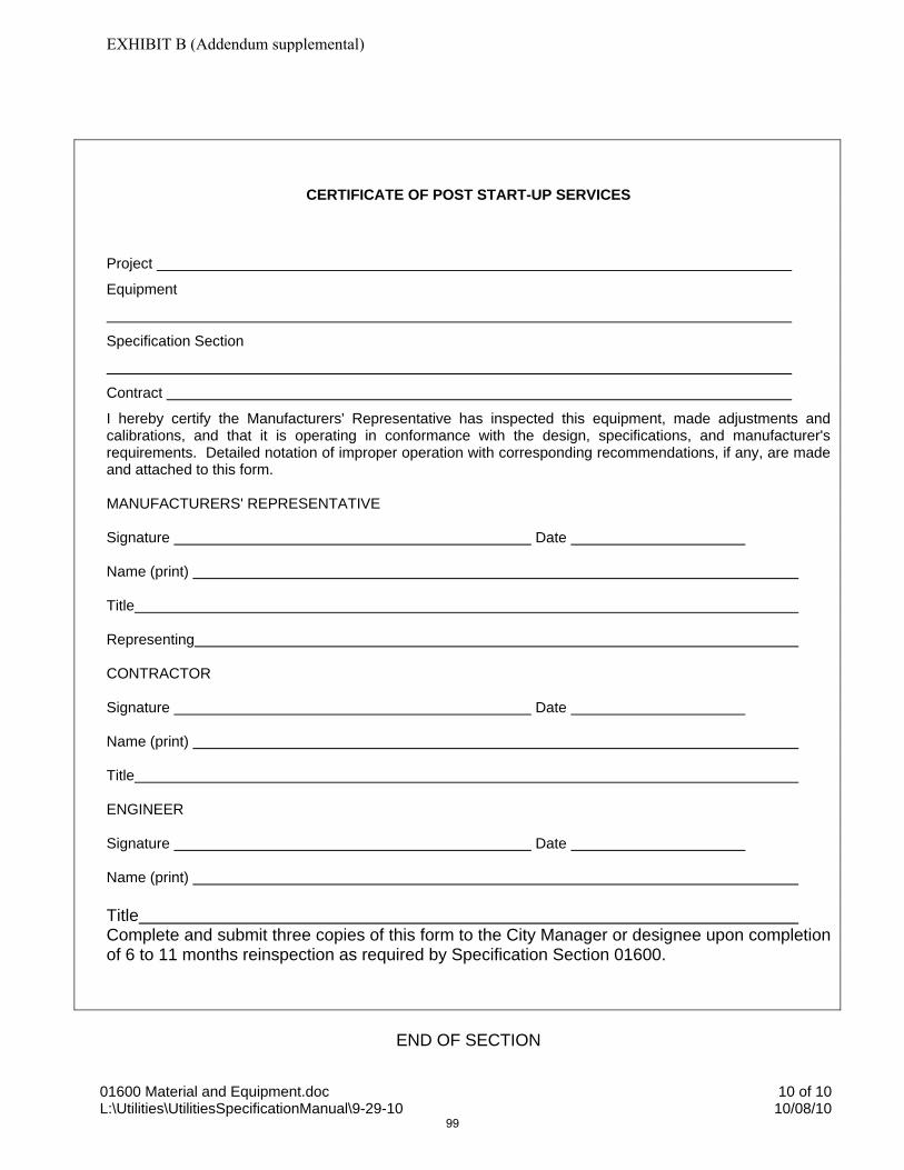
01600 Material and Equipment.doc 10 of 10 L:\Utilities\UtilitiesSpecificationManual\9-29-10 10/08/10
CERTIFICATE OF POST START-UP SERVICES
Project
Equipment
Specification Section
Contract
I hereby certify the Manufacturers' Representative has inspected this equipment, made adjustments and calibrations, and that it is operating in conformance with the design, specifications, and manufacturer's requirements. Detailed notation of improper operation with corresponding recommendations, if any, are made and attached to this form. MANUFACTURERS' REPRESENTATIVE Signature Date Name (print) Title Representing CONTRACTOR Signature Date Name (print) Title ENGINEER Signature Date Name (print) Title Complete and submit three copies of this form to the City Manager or designee upon completion of 6 to 11 months reinspection as required by Specification Section 01600.
END OF SECTION
EXHIBIT B (Addendum supplemental)
99

01710 Cleaning 1 of 4 L:\Utilities\UtilitiesSpecificationManual\9-29-10 10/08/10
SECTION 01710
CLEANING
PART 1 GENERAL
1.1 SECTION INCLUDES:
A. General Requirements B. Disposal Requirements
1.2 GENERAL REQUIREMENTS
A. Execute cleaning during progress of the work and at completion of the work. 1.3 DISPOSAL REQUIREMENTS
A. Conduct cleaning and disposal operations to comply with codes, ordinances, regulations, and anti-pollution laws.
PART 2 PRODUCTS
NOT USED
PART 3 EXECUTION
3.1 DURING CONSTRUCTION
A. Execute daily cleaning to keep the work, the site, and adjacent properties free from accumulations of waste materials, rubbish, and windblown debris, resulting from construction operations.
B. Provide onsite containers for the collection of waste materials, debris and rubbish.
All waste materials including containers, food debris and other miscellaneous materials must be disposed of daily in onsite containers.
C. Remove waste materials, debris and rubbish from the site periodically and dispose
of at legal disposal areas away from the site.
EXHIBIT B (Addendum supplemental)
100

01710 Cleaning 2 of 4 L:\Utilities\UtilitiesSpecificationManual\9-29-10 10/08/10
3.2 FINAL CLEANING
A. Requirements: At the completion of work and immediately prior to final inspection, clean the entire project as follows:
1. Thoroughly clean, sweep, wash, and polish all work and equipment provided
under the Contract, including finishes. Leave the structures and site in a complete and finished condition to the satisfaction of the ENGINEER.
2. Direct all subcontractors to similarly perform, at the same time, an equivalent
thorough cleaning of all work and equipment provided under their contracts.
3. Remove all temporary structures and all debris, including dirt, sand, gravel, rubbish and waste material.
4. Should the CONTRACTOR not remove rubbish or debris or not clean the
buildings and site as specified above, the OWNER reserves the right to have the cleaning done at the expense of the CONTRACTOR.
B. Employ experienced workers, or professional cleaners, for final cleaning.
C. Use only cleaning materials recommended by manufacturer of surface to be
cleaned.
D. In preparation for substantial completion or occupancy, conduct final inspection of sight-exposed interior and exterior surfaces, and of concealed spaces.
E. Remove grease, dust, dirt, stains, labels, fingerprints, and other foreign materials
from sight-exposed interior and exterior finished surfaces. Polish surfaces so designated to shine finish.
F. Repair, patch, and touch up marred surfaces to specified finish, to match adjacent
surfaces.
G. Replace air-handling filters if units were operated during construction.
H. Clean ducts, blowers, and coils, if air-handling units were operated without filters during construction.
I. Vacuum clean all interior spaces, including inside cabinets.
J. Handle materials in a controlled manner with as few handlings as possible. Do
not drop or throw materials from heights.
K. Schedule cleaning operations so that dust and other contaminants resulting from cleaning process will not fall on wet, newly-painted surfaces.
EXHIBIT B (Addendum supplemental)
101

01710 Cleaning 3 of 4 L:\Utilities\UtilitiesSpecificationManual\9-29-10 10/08/10
L. Clean interior of all panel cabinets, pull boxes, and other equipment enclosures.
M. Wash and wipe clean all lighting fixtures, lamps, and other electrical equipment that may have become soiled during installation.
N. Perform touch-up painting.
O. Broom clean exterior paved surfaces; rake clean other surfaces of the grounds.
P. Remove erection plant, tools, temporary structures and other materials.
Q. Remove and dispose of all water, dirt, rubbish or any other foreign substances.
3.3 FINAL INSPECTION
A. After cleaning is complete the final inspection may be scheduled. The inspection will be done with the OWNER and ENGINEER.
END OF SECTION
EXHIBIT B (Addendum supplemental)
102
01710 Cleaning 4 of 4 L:\Utilities\UtilitiesSpecificationManual\9-29-10 10/08/10
NO TEXT FOR THIS PAGE
EXHIBIT B (Addendum supplemental)
103
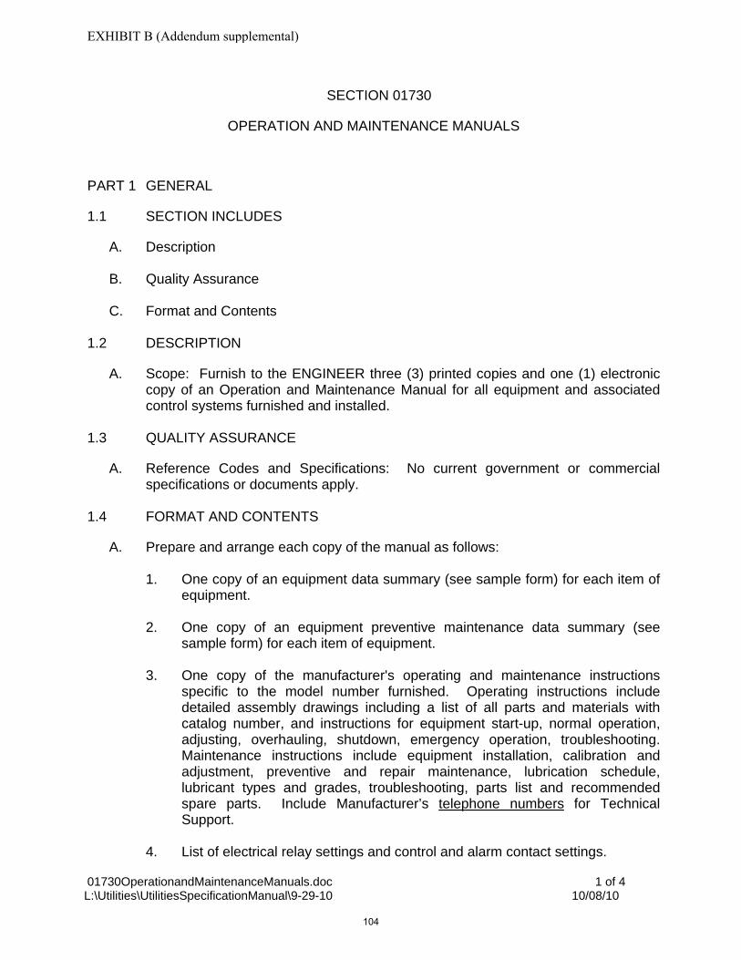
01730OperationandMaintenanceManuals.doc 1 of 4 L:\Utilities\UtilitiesSpecificationManual\9-29-10 10/08/10
SECTION 01730
OPERATION AND MAINTENANCE MANUALS
PART 1 GENERAL
1.1 SECTION INCLUDES
A. Description
B. Quality Assurance
C. Format and Contents 1.2 DESCRIPTION
A. Scope: Furnish to the ENGINEER three (3) printed copies and one (1) electronic copy of an Operation and Maintenance Manual for all equipment and associated control systems furnished and installed.
1.3 QUALITY ASSURANCE
A. Reference Codes and Specifications: No current government or commercial specifications or documents apply.
1.4 FORMAT AND CONTENTS
A. Prepare and arrange each copy of the manual as follows:
1. One copy of an equipment data summary (see sample form) for each item of equipment.
2. One copy of an equipment preventive maintenance data summary (see
sample form) for each item of equipment.
3. One copy of the manufacturer's operating and maintenance instructions specific to the model number furnished. Operating instructions include detailed assembly drawings including a list of all parts and materials with catalog number, and instructions for equipment start-up, normal operation, adjusting, overhauling, shutdown, emergency operation, troubleshooting. Maintenance instructions include equipment installation, calibration and adjustment, preventive and repair maintenance, lubrication schedule, lubricant types and grades, troubleshooting, parts list and recommended spare parts. Include Manufacturer’s telephone numbers for Technical Support.
4. List of electrical relay settings and control and alarm contact settings.
EXHIBIT B (Addendum supplemental)
104

01730OperationandMaintenanceManuals.doc 2 of 4 L:\Utilities\UtilitiesSpecificationManual\9-29-10 10/08/10
5. Electrical interconnection wiring diagram for equipment furnished including all
control and lighting systems.
6. One valve schedule giving valve number, location, fluid, and fluid destination for each valve installed. Group all valves in same piping systems together in the schedule. Obtain a sample of the valve numbering system from the ENGINEER.
7. Furnish all O&M Manual material in bound 8-1/2 by 11 commercially printed
or typed forms or an acceptable alternative format.
B. Organize each manual into sections paralleling the equipment specifications. Identify each section using heavy section dividers with reinforced holes and numbered plastic index tabs. Use 3-ring, hard-back binders. Punch all loose data for binding. Arrange composition and printing so that punching does not obliterate any data. Print on the cover and binding edge of each manual the project title, and manual title, as furnished and approved by the ENGINEER.
C. Leave all operating and maintenance material that comes bound by the equipment
manufacturer in its original bound state. Cross-reference the appropriate sections of the CONTRACTOR's O&M manual to the manufacturers' bound manuals.
D. Label binders Volume 1, 2, and so on, where more than one binder is required.
Include the table of contents for the entire set, identified by volume number, in each binder.
PART 2 PRODUCTS
Not Used
PART 3 EXECUTION
Not Used
END OF SECTION
EXHIBIT B (Addendum supplemental)
105

01730OperationandMaintenanceManuals.doc 3 of 4 L:\Utilities\UtilitiesSpecificationManual\9-29-10 10/08/10
City Utilities
________________________
Equipment Data Summary Equipment Name: Specification Reference: Manufacturer: Name:
Address:
Telephone: Number Supplied: Location/Service: Model No: Serial No: Type: Size/Speed/Capacity/Range (as applicable): Power Requirement (Phase/Volts/Hertz): Local Representative: Name:
Address:
Telephone: NOTES:
EXHIBIT B (Addendum supplemental)
106
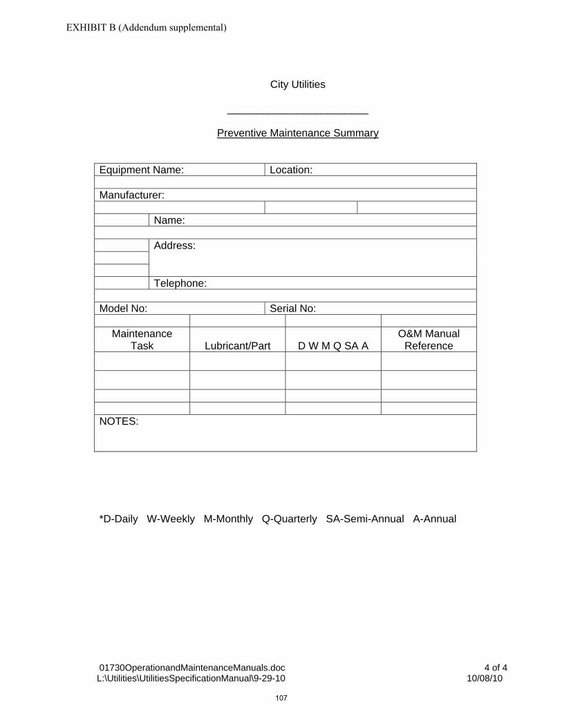
01730OperationandMaintenanceManuals.doc 4 of 4 L:\Utilities\UtilitiesSpecificationManual\9-29-10 10/08/10
City Utilities
________________________
Preventive Maintenance Summary
Equipment Name: Location: Manufacturer: Name:
Address:
Telephone: Model No: Serial No:
Maintenance
Task Lubricant/Part D W M Q SA A O&M Manual
Reference
NOTES: *D-Daily W-Weekly M-Monthly Q-Quarterly SA-Semi-Annual A-Annual
EXHIBIT B (Addendum supplemental)
107

01750 Project Record Documents.doc 1 of 4 L:\Utilities\UtilitiesSpecificationManual\9-29-10 10/08/10
SECTION 01750
PROJECT RECORD DOCUMENTS
PART 1 GENERAL
1.1 SECTION INCLUDES
Requirements for preparation, maintenance and submittal of project record documents. The Contractor's attention is specifically directed to Part 3.2.B. of this Section, which requires use of a Florida licensed surveyor to sign and seal all record drawings.
1.2 RELATED SECTIONS
A. Section 01051 – Lines and Grades
B. Section 01400 - Quality Control
1.3 SUBMITTALS
A. General: Provide all submittals as specified. Final disbursement of project monies shall not occur until or unless said “record drawings” are submitted to the satisfaction of the City.
B. At Contract close out, two (2) sets of signed and sealed Record Drawings for the potable water system, non-potable irrigation water system, and/or wastewater system to be conveyed shall be submitted to the City.
C. Provide electronic submittal as specified in Part 3.2.B of this Section.
1.4 REQUIREMENTS
A. Contractor shall maintain at the site for the City one record copy of:
1. Drawings
2. Specifications
3. Addenda
4. Change orders and other modifications to the Contract
5. Design Engineer’s field orders or written instructions
6. Approved shop drawings, working drawings and samples
7. Field test records
B. Additional Requirements for City Capital Projects Only
1. GIS Turn-Over Documents (see City of Naples GIS and CAD Record Standards and Requirements)
PART 2 PRODUCTS (not used)
EXHIBIT B (Addendum supplemental)
108

01750 Project Record Documents.doc 2 of 4 L:\Utilities\UtilitiesSpecificationManual\9-29-10 10/08/10
PART 3 EXECUTION
3.1 MAINTENANCE OF DOCUMENTS AND SAMPLES
A. Project record documents shall be stored in Contractor’s field office or other location approved by the City apart from documents used for construction.
B. Maintain documents in a clean, dry, legible condition and in good order. Do not use record documents for construction purposes.
C. Make documents and samples available at all times for inspection by the City.
3.2 RECORDING
A. General
1. Record Drawings shall accurately depict the constructed configuration of all potable water, non-potable irrigation water and/or wastewater systems or portion(s) thereof. All revisions to City staff approved construction drawings shall be precisely identified and illustrated on the Record Drawings. All Record Drawings of utility systems or portion(s) thereof that are not being conveyed to the Board shall bear, on the cover sheet, a prominently displayed DISCLAIMER, in bold lettering at least one-quarter (1/4) inch high, stating: "All on-site potable water, non-potable irrigation and/or wastewater systems shall be owned, operated and maintained by the private owner(s) and/or the master condominium/homeowners’ association, successors or assigns" (or other comparable private ownership).
2. Label each document “PROJECT RECORD” or similar text in neat, large printed letters.
3. Survey information can be obtained as needed by the use of 2-inch PVC labeled pipes installed over underground improvements by the contractor during construction. This method is an adequate process for obtaining record information.
4. Record information in red ink.
B. Record Drawings
1. The Record Drawings require signed and sealed as-built information, including above and below ground improvements including underground piping, valves and ductbanks, by a Florida Licensed Land Surveyor.
2. The Record Drawings shall identify the entity that provided the record data.
3. Drawings shall be referenced to and tie-in with the state plane coordinate system, with a Florida East Projection, and a North American Datum 1983/1990 (NAD 83/90 datum), and with United States Survey Feet (USFEET) units, as established by a registered Florida surveyor and mapper.
4. Files shall be also submitted in Drawing File (DWG) format in AutoCAD Release 2004 or later version and a red-lined “field” hardcopy.
EXHIBIT B (Addendum supplemental)
109

01750 Project Record Documents.doc 3 of 4 L:\Utilities\UtilitiesSpecificationManual\9-29-10 10/08/10
5. Record drawings shall be submitted to the City staff within 60 days of the final construction completion date.
6. The following items shall be accurately depicted in vertical and horizontal directions on the Record Drawings:
a) All associated rights-of-way and utility easements whether shown on the
Contract Drawings, found during construction or added during the Work.
b) Sewer system inverts, pipe slopes, manhole rims and run lengths.
c) Sewer lateral locations stationed from the nearest downstream manhole.
d) Sewer main stub extension inverts at both ends, pipe slope, run length and location.
e) Tie-ins to all valves, air release assemblies, fire hydrants, manholes, blowoffs, etc.
f) Top elevations of treatment plant structures and tanks.
g) Manhole center for sanitary sewers and storm sewers as related to utility improvements.
h) Pipe changes in direction or slope.
i) Buried valves, tees and fittings.
j) Pipe invert, or centerline, elevations at crossing with other pipe.
k) Invert, or centerline, elevations and coordinates of existing exposed pipe at crossing with underground pipe installed under this project.
l) Other horizontal and vertical record data pertinent to completed Work.
7. Each pipe elevation shall be clearly identified as to whether it is top of pipe, centerline of pipe or invert of pipe.
8. Record Drawings shall indicate all deviations from Contract Drawings including:
a) Field changes.
b) Changes made by Change Order.
c) Details, utilities, piping or structures not on original Contract Drawings.
d) Equipment and piping relocations.
C. Specifications and Addenda
Legibly mark each Section to record:
2. Manufacturer, trade name, catalog number and supplier of each product and item of equipment actually installed.
3. Changes made by Field Order or Change Order.
D. Shop Drawings
1. Keep one copy of the final, approved shop drawing with the Record Documents.
EXHIBIT B (Addendum supplemental)
110

01750 Project Record Documents.doc 4 of 4 L:\Utilities\UtilitiesSpecificationManual\9-29-10 10/08/10
2. Record documents should include all shop drawing information submitted. Additional information submitted during the review process should be filed with the appropriate submittal.
END OF SECTION
EXHIBIT B (Addendum supplemental)
111
02050 Demolition.doc 1 of 4 L:\Utilities\UtilitiesSpecificationManual\9-29-10 10/08/10
SECTION 02050
DEMOLITION
PART 1 GENERAL
1.1 SUMMARY
A. Section Includes: All work necessary for the removal and disposal of structures, foundations, piping, equipment and roadways, or any part thereof including masonry, steel, reinforced concrete, plain concrete, electrical facilities, and any other material or equipment shown or specified to be removed.
B. Basic Procedures and Schedule: Carry out demolition so that adjacent structures,
which are to remain, are not endangered. Schedule the work so as not to interfere with the day-to-day operation of the existing facilities. Do not block doorways or passageways in existing facilities.
C. Additional Requirements: Provide dust control and make provisions for safety.
D. Related Work Specified in Other Sections Includes:
1. Section 01045 – Connection to Existing Systems 2. Section 02110 – Site Clearing
1.2 SUBMITTALS
A. Provide all submittals, including the following, as specified in Division 1.
B. Site Inspection: Visit the site and inspect all existing structures. Observe and record any defects that may exist in buildings or structures adjacent to but not directly affected by the demolition work. Provide the City Manager or designee with a copy of this inspection record and obtain the ENGINEER's and the City's Manager or designee approval prior to commencing the demolition.
1.3 QUALITY ASSURANCE
A. Limits: Exercise care to break concrete well for removal in reasonably small masses. Where only parts of a structure are to be removed, cut the concrete along limiting lines with a suitable saw so that damage to the remaining structure is held to a minimum.
PART 2 PRODUCTS
Not Used
EXHIBIT B (Addendum supplemental)
112

02050 Demolition.doc 2 of 4 L:\Utilities\UtilitiesSpecificationManual\9-29-10 10/08/10
PART 3 EXECUTION
3.1 EXAMINATION OF EXISTING DRAWINGS
A. Available drawings of existing structures and equipment will be available for inspection at the office of the ENGINEER.
3.2 PROTECTION
A. General Safety: Provide warning signs, protective barriers, and warning lights as necessary adjacent to the work as approved or required. Maintain these items during the demolition period.
B. Existing Services: Undertake no demolition work until all mechanical and
electrical services affected by the work have been properly disconnected. Cap, reroute or reconnect interconnecting piping or electrical services that are to remain in service either permanently or temporarily in a manner that will not interfere with the operation of the remaining facilities.
C. Hazards: Perform testing and air purging where the presence of hazardous
chemicals, gases, flammable materials or other dangerous substances is apparent or suspected, and eliminate the hazard before demolition is started.
3.3 DEMOLITION REQUIREMENTS
A. Explosives: The use of explosives will not be permitted.
B. Protection: Carefully protect all mechanical and electrical equipment against dust and debris.
C. Removal: Remove all debris from the structures during demolition and do not
allow debris to accumulate in piles. D. Abandoned Pipelines: Fill all abandoned pipelines using grout in accordance with
Section 03310.
E. Access: Provide safe access to and egress from all working areas at all times with adequate protection from falling material.
F. Protection: Provide adequate scaffolding, shoring, bracing railings, toe boards
and protective covering during demolition to protect personnel and equipment against injury or damage. Cover floor openings not used for material drops with material substantial enough to support any loads placed on it. Properly secure the covers to prevent accidental movement.
G. Lighting: Provide adequate lighting at all times during demolition.
H. Closed Areas: Close areas below demolition work to anyone while removal is in
progress.
EXHIBIT B (Addendum supplemental)
113

02050 Demolition.doc 3 of 4 L:\Utilities\UtilitiesSpecificationManual\9-29-10 10/08/10
I. Material Drops: Do not drop any material to any point lying outside the exterior walls of the structure unless the area is effectively protected.
J. Chemicals: All chemicals used during project construction or furnished for project
operation, whether herbicide, pesticide, disinfectant, polymer, reactant or of other classification must show approval of either EPA or USDA. Use of all such chemicals and disposal of residues shall be in strict conformance with manufacturer's instructions or government regulations as applicable.
3.4 ASBESTOS-CONCRETE (AC) PIPE
A. If existing asbestos-cement pipe is encountered during the course of construction, remove the AC pipe and replace it with C900 PVC pipe having a pressure rating as required elsewhere in these specifications. Replace the AC pipe with PVC pipe for a distance of 10 feet each way from the centerline of the pipe under construction or 5 feet beyond the length of AC pipe exposed by trench excavation, whichever is greater. A change order will be issued for required replacement of AC pipe not shown on the drawings.
B. Coordinate the shutdown of the AC pipeline with the City Manager or designee in
accordance with Section 01045, including proper notice to the City Manager or designee and any customers that may be affected by the shutdown as required by these specifications and/or current Water Department policy. In the event of an unanticipated encounter with AC pipe, immediately recover and protect the pipe and notify the CITY Water Department.
C. Perform cutting of AC pipe by means of cutting wheels mounted in a chain
wrapped around the pipe barrel. Do not use power driven saws with abrasive discs or any other means that produce concentrations of airborne asbestos dust.
3.5 DISPOSAL OF MATERIALS
A. Final Removal: Dispose of AC pipe in accordance with CITY special handling requirements and coordination with City Solid Waste Management Department. Remove all other debris, rubbish, scrap pieces, equipment, and materials resulting from the demolition. Take title to all demolished materials and remove such items from the site.
END OF SECTION
EXHIBIT B (Addendum supplemental)
114

02050 Demolition.doc 4 of 4 L:\Utilities\UtilitiesSpecificationManual\9-29-10 10/08/10
NO TEXT FOR THIS PAGE
EXHIBIT B (Addendum supplemental)
115

02110 Site Clearing.doc 1 of 4 L:\Utilities\UtilitiesSpecificationManual\9-29-10 10/08/10
SECTION 02110
SITE CLEARING
PART 1 GENERAL
1.1 SUMMARY
A. Section Includes: Requirements for clearing of all areas within the Contract limits and other areas shown, including work designated in permits and other agreements, in accordance with the requirements of Division 1.
B. Related Work Specified in Other Sections Includes:
1. Section 02050 – Demolition 2. Section 02222 - Excavation - Earth and Rock 3. Section 02223 – Backfilling 4. Section 02400 – Restoration by Sodding or Seeding
1.2 DEFINITIONS
A. Clearing: Clearing is the removal from the ground surface and disposal, within the designated areas, of trees, brush, shrubs, down timber, decayed wood, other vegetation, rubbish and debris as well as the removal of fences.
B. Grubbing: Grubbing is the removal and disposal of all stumps, buried logs, roots
larger than 1-1/2 inches, matted roots and organic materials.
PART 2 PRODUCTS
Not Used
PART 3 EXECUTION
3.1 PROTECTION OF EXISTING UTILITIES
A. Prior to site clearing, locate and mark all existing utilities in coordination with the CITY and other affected owners. Protect all existing utilities and markings from damage. In case of damage to existing utilities caused by construction activities, contact the owner of the utility or appropriate CITY department (Water or Wastewater) immediately. Repair any damage to existing utilities or markings caused by construction activities in coordination with or as directed by the owner of the utility.
EXHIBIT B (Addendum supplemental)
116

02110 Site Clearing.doc 2 of 4 L:\Utilities\UtilitiesSpecificationManual\9-29-10 10/08/10
3.2 TREE REMOVAL
A. Tree Removal Within Right-of-Way Limits: Remove trees and shrubs within the right-of-way unless otherwise indicated.
1. Remove trees and shrubs to avoid damage to trees and shrubs designated
to remain.
2. Grub and remove tree stumps and shrubs felled within the right-of-way to an authorized disposal site. Fill depressions created by such removal with material suitable for backfill as specified in Section 02223.
B. Tree Removal Outside Right-of-Way Limits: Do not cut or damage trees outside
the right-of-way unless plans show trees to be removed or unless written permission has been obtained from the property owner. Furnish three copies of the written permission before removal operations commence.
C. If the landowner desires the timber or small trees, cut and neatly pile it in 4 ft.
lengths for removal by the owner; otherwise, dispose of it by hauling it away from the project site. If hauled timber is of merchantable quality, credit shall accrue to the CONTRACTOR.
3.3 TREES AND SHRUBS TO BE SAVED
A. Protection: Protect trees and shrubs within the work limits that are so delineated or are marked in the field to be saved from defacement, injury and destruction.
1. Work within the limits of the tree drip line with extreme care using either
hand tools or equipment that will not cause damage to trees.
a. Do not disturb or cut roots unnecessarily. Do not cut roots 1-1/2 inches and larger unless approved.
b. Immediately backfill around tree roots after completion of construction
in the vicinity of trees.
c. Do not operate any wheeled or tracked equipment within drip line.
2. Protect vegetation from damage caused by emissions from engine-powered equipment.
3. During working operations, protect the trunk, foliage and root system of all
trees to be saved with boards or other guards placed as shown and as required to prevent damage, injury and defacement.
a. Do not pile excavated materials within the drip line or adjacent to the
trunk of trees.
b. Do not allow runoff to accumulate around trunk of trees.
EXHIBIT B (Addendum supplemental)
117
02110 Site Clearing.doc 3 of 4 L:\Utilities\UtilitiesSpecificationManual\9-29-10 10/08/10
c. Do not fasten or attach ropes, cables, or guy wires to trees without
permission. When such permission is granted, protect the tree before making fastening or attachments by providing burlap wrapping and softwood cleats.
d. The use of axes or climbing spurs for trimming will not be permitted.
e. Provide climbing ropes during trimming.
4. Remove shrubs to be saved, taking a sufficient earth ball with the roots to
maintain the shrub.
a. Temporarily replant if required, and replace at the completion of construction in a condition equaling that which existed prior to removal.
b. Replace in kind if the transplant fails.
5. Have any tree and shrub repair performed by a tree surgeon properly
licensed by the State of Florida and within 24 hours after damage occurred. 3.4 CLEARING AND GRUBBING
A. Clearing: Clear all items specified to the limits shown and remove cleared and grubbed materials from the site.
1. Do not start earthwork operations in areas where clearing and grubbing is
not complete, except that stumps and large roots may be removed concurrent with excavation.
2. Comply with erosion, sediment control and storm management measures as
specified in Division 1.
B. Grubbing: Clear and grub areas to be excavated, areas receiving less than 3 feet of fill and areas upon which structures are to be constructed.
1. Remove stumps and root mats in these areas to a depth of not less than 18
inches below the subgrade of sloped surfaces.
2. Fill all depressions made by the removal of stumps or roots with material suitable for backfill as specified in Section 02223.
C. Limited Clearing: Clear areas receiving more than 3 feet of fill by cutting trees and
shrubs as close as practical to the existing ground. Grubbing will not be required. D. Dispose of all material and debris from the clearing and grubbing operation by
hauling such material and debris away to an approved dump. The cost of disposal (including hauling) of cleared and grubbed material and debris shall be considered
EXHIBIT B (Addendum supplemental)
118

02110 Site Clearing.doc 4 of 4 L:\Utilities\UtilitiesSpecificationManual\9-29-10 10/08/10
a subsidiary obligation of the CONTRACTOR; include the cost in the bid for the various classes of work.
3.5 TOPSOIL
A. Stripping: Strip existing topsoil from areas that will be excavated or graded prior to commencement of excavating or grading and place in well-drained stockpiles in approved locations.
END OF SECTION
EXHIBIT B (Addendum supplemental)
119

02151 Shoring, Sheeting and Bracing.doc 1 of 4 L:\Utilities\UtilitiesSpecificationManual\9-29-10 10/08/10
SECTION 02151
SHORING, SHEETING AND BRACING
PART 1 GENERAL
1.1 SUMMARY
A. Section Includes: Work required for protection of an excavation or structure through shoring, sheeting, and bracing.
B. Related Work Specified In Other Sections Includes:
1. Section 02222 - Excavation - Earth and Rock 2. Section 02223 - Backfilling
1.2 SUBMITTALS
A. General: Provide all submittals, including the following, as specified in Division 1.
B. CONTRACTOR's Submittals: All sheeting and bracing shall be the responsibility of the CONTRACTOR to retain qualified design services for these systems, and to be completed with strict adherence to OSHA Regulations. Submit complete design calculations and working drawings of proposed shoring, sheeting and bracing which have been prepared, signed and sealed by a Licensed Professional Engineer experienced in Structural Engineering and registered in the State of Florida, before starting excavation for jacking pits and structures. Use the soil pressure diagram shown for shoring, sheeting and bracing design. ENGINEER's review of calculations and working drawings will be limited to confirming that the design was prepared by a licensed professional engineer and that the soil pressure diagram shown was used.
1.3 REFERENCES
A. Design: Comply with all Federal and State laws and regulations applying to the design and construction of shoring, sheeting and bracing.
B. N.B.S. Building Science Series 127 "Recommended Technical Provisions for
Construction Practice in Shoring and Sloping Trenches and Excavations. 1.4 QUALITY ASSURANCE
A. Regulatory Requirements: Do work in accordance with the U.S. Department of Labor Safety and Health Regulations for construction promulgated under the Occupational Safety Act of 1970 (PL 91-596) and under Section 107 of the Contract Work Hours and Safety Standards Act (PL 91-54), and the Florida
EXHIBIT B (Addendum supplemental)
120

02151 Shoring, Sheeting and Bracing.doc 2 of 4 L:\Utilities\UtilitiesSpecificationManual\9-29-10 10/08/10
Trench Safety Act. Observe 29 CFR 1910.46 OSHA regulations for Confined Space Entry.
PART 2 PRODUCTS
2.1 MANUFACTURERS AND MATERIALS
A. Material Recommendations: Use manufacturers and materials for shoring, sheeting and bracing as recommended by the Licensed Professional Engineer who designed the shoring, sheeting, and bracing.
1. Wood Materials: Oak, or treated fir or pine for wood lagging.
PART 3 EXECUTION
3.1 SHORING, SHEETING AND BRACING INSTALLATION
A. General: Provide safe working conditions, to prevent shifting of material, to prevent damage to structures or other work, to avoid delay to the work, all in accordance with applicable safety and health regulations. Properly shore, sheet, and brace all excavations which are not cut back to the proper slope and where shown. Meet the general trenching requirements of the applicable safety and health regulations for the minimum shoring, sheeting and bracing for trench excavations.
1. CONTRACTOR's Responsibility: Sole responsibility for the design, methods
of installation, and adequacy of the shoring, sheeting and bracing.
B. Arrange shoring, sheeting and bracing so as not to place any strain on portions of completed work until the general construction has proceeded far enough to provide ample strength.
C. If ENGINEER is of the opinion that at any point the shoring, sheeting or bracing
are inadequate or unsuited for the purpose, resubmission of design calculations and working drawings for that point may be ordered, taking into consideration the observed field conditions. If the new calculations show the need for additional shoring, sheeting and bracing, it should be installed immediately.
D. Monitoring: Periodically monitor horizontal and vertical deflections of sheeting.
Submit these measurements for review.
E. Accurately locate all underground utilities and take the required measures necessary to protect them from damage. Keep all underground utilities in service at all times as specified in Division 1.
F. Driven Sheeting: Drive tight sheet piling in that portion of any excavation in paved
or surface streets City collector and arterial streets and in State, County, and City
EXHIBIT B (Addendum supplemental)
121

02151 Shoring, Sheeting and Bracing.doc 3 of 4 L:\Utilities\UtilitiesSpecificationManual\9-29-10 10/08/10
highways below the intersection of a one-on-one slope line from the nearest face of the excavation to the edge of the existing pavement or surface.
G. Sheeting Depth: In general drive or place sheeting for pipelines to a depth at
elevation equal to the top of the pipe as approved.
1. If it is necessary to drive sheeting below that elevation in order to obtain a dry trench or satisfactory working conditions, cut the sheeting off at the top of the pipe and leave in place sheeting below the top of the pipe.
2. Do not cut the sheeting until backfill has been placed and compacted to the
top of the pipe.
H. Sheeting Removal: In general, remove sheeting and bracing above the top of the pipe as the excavation is refilled in a manner to avoid the caving in of the bank or disturbance to adjacent areas or structures. Remove sheeting as backfilling progresses so that the sides are always supported or when removal would not endanger the construction of adjacent structures. When required to eliminate excessive trench width or other damages, shoring or bracing shall be left in place and the top cut off at an elevation 2.5 feet below finished grade, unless otherwise directed.
1. Carefully fill voids left by the withdrawal of the sheeting by jetting, ramming
or otherwise.
2. No separate payment will be made for filling of such voids.
END OF SECTION
EXHIBIT B (Addendum supplemental)
122

02151 Shoring, Sheeting and Bracing.doc 4 of 4 L:\Utilities\UtilitiesSpecificationManual\9-29-10 10/08/10
NO TEXT FOR THIS PAGE
EXHIBIT B (Addendum supplemental)
123
02210 Pipe Removal and Abandonment 1 of 5 L:\Utilities\UtilitiesSpecificationManual\9-29-10 10/08/10
SECTION 02210
PIPE REMOVAL AND ABANDONMENT
PART 1 GENERAL
1.1 SUMMARY
A. Section Includes: Removal and abandonment of piping and appurtenances, wholly or in part, as required to complete Work as shown on the Drawings and specified in this Section.
B. Work on and/or removal of asbestos cementitious pipe shall be performed per OSHA, EPA, NESHAPS, and State regulations and must be supervised by a person that has satisfactorily completed an Asbestos Abatement Project Supervisor course.
C. Related Work Specified in other Sections Includes:
1. Section 01045 – Connection to Existing Systems
2. Section 02222 – Excavation – Earth and Rock
3. Section 02223 – Backfilling
4. Section 03310 – Concrete, Masonry Mortar and Grout
1.2 SUBMITTALS
A. General: Provide all submittals, including the following, as specified in Division 1.
B. Submit the following:
1. Proposed methods for pipe removal and abandonment;
2. Equipment proposed to be used to do pipe removal and abandonment work;
3. Resume of pipe grouting subcontractor;
4. Pipe removal and abandonment schedule/sequence.
C. If a detour is required, submit a traffic control plan for approval to City Manager or designee and/or the Florida Department of Transportation as described in Section 01570.
1.3 SITE CONDITIONS
A. General
1. Prior to any work, a proper and approved maintenance of traffic plan (MOT) shall be submitted to the engineer and the City.
2. Execute pipe removal and abandonment so that there is no injury to persons or damage to adjacent buildings, structures, equipment, materials, piping, wiring, pavement, fences, trees, guardrails, and other adjacent improvements. Execute demolition and abandonment so that access to facilities that are in operation and to residences and businesses is free and safe.
EXHIBIT B (Addendum supplemental)
124

02210 Pipe Removal and Abandonment 2 of 5 L:\Utilities\UtilitiesSpecificationManual\9-29-10 10/08/10
3. Execute pipe removal and abandonment so that interference to vehicular traffic and personnel traffic does not exceed scheduled interference. Do not place rubble, excavation, piping, or other materials removed on roadways, drives, or sidewalks that are to remain in service.
PART 2 - PRODUCTS
2.1 TEMPORARY MATERIALS
A. Provide temporary fencing, barricades, barriers, piping, valves, pumps, power and controls, and water necessary to meet the requirements of this Section.
B. Temporary fencing, barricades, barriers, and enclosures shall be suitable to the purpose intended.
2.2 REPAIR AND REPLACEMENT MATERIALS
For repair or replacement of existing facilities or improvements to remain, use materials identical to, or equal to, materials used in existing work when new.
PART 3 – EXECUTION
3.1 GENERAL
A. Conduct pipe removal and abandonment as shown and specified in the Contract Documents.
B. Conduct pipe removal and abandonment so that existing equipment, piping, wiring, structures, and other improvements to remain are not damaged. Repair or replace equipment, piping, wiring, structures, and other improvements damaged at no additional cost to the City.
C. Do not remove equipment, piping, wiring, structures, or other improvements not shown or specified to be removed. If equipment, piping, wiring, structures, or other improvements not shown or specified to be removed is removed, replace equipment, piping, wiring, structures, or other improvements at no additional cost to the City.
3.2 DISCONNECTIONS
A. Prior to starting pipe removal or abandonment, check underground and exposed existing utilities, piping, and equipment within the limits of pipe removal or abandonment. Prior to starting, check underground and exposed existing utilities, piping connected to and associated with existing pipe to be removed or abandoned. Verify the following:
1. Piping is inactive (abandoned);
2. Other utilities which may be in conflict have been permanently or temporarily disconnected, if required:
B. Do not proceed with salvage or demolition if piping is active or utilities have not been disconnected.
EXHIBIT B (Addendum supplemental)
125

02210 Pipe Removal and Abandonment 3 of 5 L:\Utilities\UtilitiesSpecificationManual\9-29-10 10/08/10
3.3 ABANDONMENT
A. The Contractor shall, as described on the Drawings and as may be directed by the City, abandon in place the following existing utility improvements:
1. All water mains, reuse water mains and raw water mains that are designated to be abandoned shall be filled with grout. Refer to Section 03310 – Concrete, Masonry Mortar and Grout.
2. All sewer lines, force mains, laterals and services that are designated to be abandoned shall be flushed clean and filled with grout. Prior to grout fill, sewer lines, force mains, laterals and services to be abandoned shall be flushed clean to remove wastewater and solids. Contractor is responsible for securing and providing flushing water, collection of flush water/wastewater, and disposal. The cleaning of these piping systems shall comply with all local and DEP requirements.
3. Sewer manholes designated to be abandoned shall have the top two feet removed. The remainder of each manhole shall be abandoned and filled with grout or flowable fill. The excavation or pit shall be backfilled with select fill and compacted in accordance with Section 02223 – Backfilling and the trenching details on the Drawings.
B. Appurtenances: All water hydrants, ARV valves and other appurtenances on abandoned lines shall be removed to the main and the fitting at the main shall be capped or plugged. All valves shall have the valve box, pad and operator removed, with the valve left in the open position unless specifically noted otherwise.
C. Preparation:
1. The City shall be notified at least 72 hours in advance of grouting operations.
2. Bulkheads shall be spaced at intervals of not more than 1,000 feet. If the line to be abandoned is longer, bulkheads shall be inserted in the pipe to maintain the required maximum spacing between bulkheads.
3. Temporary vents shall be installed in the line to be filled at a maximum spacing of 150 ft. The vents shall be capable of being capped to allow further grouting operations.
D. Equipment:
1. The materials shall be mixed or delivered in equipment of sufficient size and capacity to provide the desired amount of grout material for each stage in a single operation. The equipment shall be capable of mixing the grout at densities required for the approved procedure and shall also be capable of changing density as dictated by field conditions any time during the grouting operation.
2. Mixers and Pumps - The grout shall be delivered to the injection point at a steady pressure with a non-pulsating centrifugal or triplex pump. Means shall be provided to increase or decrease the water-cement ratio. The system shall mix the grout to a homogeneous consistency. Means of accurately measuring grout component quantities, pumping pressures, and volumes pumped shall be provided.
EXHIBIT B (Addendum supplemental)
126

02210 Pipe Removal and Abandonment 4 of 5 L:\Utilities\UtilitiesSpecificationManual\9-29-10 10/08/10
3. Pressure Gauges - CONTRACTOR shall provide one pressure gauge at the point of injection and one pressure gauge at the grout pump. Grouting shall not proceed without appropriate calibrated gauges in place and in working order. Pressure gauges shall be equipped with diaphragm seals, have a working range between 1.5 to 2.0 times the design grout pressure, and have an accuracy within 0.5 percent of full range. Pressure gauges shall be instrument oil filled and attached to a saddle-type diaphragm seal to prevent clogging with grout.
E. Grouting:
Once grouting operations begin, grouting shall proceed uninterrupted from bulkhead to bulkhead. Grout placement shall not be terminated until both of the following conditions have been met, unless otherwise approved by the City: a) The estimated volume of grout to fill the line has been injected; and, b) grout has been expelled from the furthest vent or bulkhead. Bulkheads and temporary vents shall not be removed until the grout has set.
F. Testing and Sampling: 1. Take four test specimens for each 50 cubic yards of grout or for each four hours
of placing. 2. Test in accordance with ASTM C109 except:
a. The specimens shall be 3 inch by 6 inch cylinders covered after casting to prevent damage and loss of moisture. Moist cure specimens for a period up to 7 days prior to a 28-day compressive strength test.
b. Do not oven dry specimens that are load tested. Specimens may be tested at any age to monitor compressive strength. The material may require special handling and testing techniques.
G. The CONTRACTOR may remove the pipe in accordance with the Paragraph 3.04 in
lieu of abandonment if acceptable to the City. Such removal, however, will be paid at the same price for pipe abandonment.
H. All work under this Section shall comply with City, City, State and Federal regulations.
3.4 REMOVAL AND DISPOSAL
A. The Contractor shall, as described on the Drawings and as may be directed by the City, remove the following existing utility improvements:
1. All water mains, reuse water mains and raw water mains that are designated to be removed.
2. All sewer lines, sewer manholes, force mains, laterals and services that are designated to be removed shall be flushed clean with water prior to removal. Contractor is responsible for securing and providing flushing water, collection of flush water/wastewater, and disposal. The cleaning of these piping systems shall comply with all local and DEP requirements.
B. The pipe removal and disposal shall include all valves, fittings and appurtenances.
EXHIBIT B (Addendum supplemental)
127

02210 Pipe Removal and Abandonment 5 of 5 L:\Utilities\UtilitiesSpecificationManual\9-29-10 10/08/10
3.5 SALVAGE OF EQUIPMENT, PIPING, AND MATERIALS
A. Remove items identified on the drawings or specified to remain the property of the City. Do not damage equipment, piping, and materials to be salvaged.
B. Following removal or equipment, piping, and materials to be salvaged, place equipment, piping, and materials in a location within the City limits as designated by the City.
3.6 REPAIRS
Repair structural elements, equipment, piping, conduit, and other improvements to remain that are damaged during demolition. Use workers specifically qualified in trade, or trades, involved to repair damaged work.
3.7 DISPOSAL
A. Remove and dispose of all equipment, piping, and materials from the jobsite not specifically designated to be retained by the City.
B. Contractor shall not accumulate or store debris from demolition on the project site.
C. The disposal of the piping, manholes and appurtenances shall be in accordance with City, State and Federal laws.
3.8 BACKFILLING
A. Backfill excavations, trenches, and pits resulting from abandonment and removal according to Section 02223 – Backfilling.
B. Backfill of the pipe trenches shall be according to the City details for pipe trench backfill. Pipe trenches for removed pipes that were within 3 horizontal feet of the edge of pavement shall be backfilled according to the detail for the type of roadway.
3.9 CLEANUP AND CLOSURE
A. Following pipe abandonment or removal, clean-up areas where other work is to be done as specified in this Section, or Sections applicable to work to be done.
B. Following pipe abandonment or removal, clean-up areas where no other work is to be done under this Contract. Remove debris and rubbish, temporary facilities, and equipment. Level surface irregularities to eliminate depressions. Leave work in a neat and presentable condition.
C. In locations where a pipe to be abandoned or removed connects to a pipe that remains in service, the Contractor shall install a suitable cap or plug on the end of the active pipe.
END OF SECTION
EXHIBIT B (Addendum supplemental)
128

02222 Excavation – Earth and Rock.doc 1 of 8 L:\Utilities\UtilitiesSpecificationManual\9-29-10 10/08/10
SECTION 02222
EXCAVATION - EARTH AND ROCK
PART 1 GENERAL
1.1 SUMMARY
A. Section Includes: Requirements for performing opencut excavations to the widths and depths necessary for constructing structures and pipelines, including excavation of any material necessary for any purpose pertinent to the construction of the Work.
B. Related Work Specified In Other Sections Includes:
1. Section 02110 - Site Clearing 2. Section 02151 - Shoring, Sheeting and Bracing 3. Section 02223 – Backfilling 4. Section 02530 – Groundwater Control for Open Cut Excavation 5. Section 03310 – Concrete, Masonry, Mortar and Grout
1.2 DEFINITIONS
A. Earth: "Earth" includes all materials which, in the opinion of the ENGINEER, do not require blasting, barring, wedging or special impact tools for their removal from their original beds, and removal of which can be completed using standard excavating equipment. Specifically excluded are all ledge and bedrock and boulders or pieces of masonry larger than one cubic yard in volume.
B. Rock: "Rock" includes all materials which, in the opinion of the ENGINEER,
require blasting, barring, wedging and/or special impact tools such as jack hammers, sledges, chisels, or similar devices specifically designed for use in cutting or breaking rock for removal from their original beds and which have compressive strengths in their natural undisturbed state in excess of 300 psi. Boulders or masonry larger than one cubic yard in volume are classed as rock excavation.
1.3 SUBMITTALS
A. General: Provide all submittals, including the following, as specified in Division 1.
B. Engage the services of a Professional Engineer who is registered in the State of Florida to design all cofferdam and sheeting and bracing systems which the CONTRACTOR feels necessary for the execution of his work. Submit to the
EXHIBIT B (Addendum supplemental)
129
02222 Excavation – Earth and Rock.doc 2 of 8 L:\Utilities\UtilitiesSpecificationManual\9-29-10 10/08/10
ENGINEER a signed statement that he has been employed by the CONTRACTOR to design all sheeting and bracing systems. After the systems have been installed, furnish to the ENGINEER an additional signed statement that the cofferdams and sheeting and bracing systems have been installed in accordance with his design.
C. If a detour is required, submit a traffic control plan for approval to City Manager or
designee and/or the Florida Department of Transportation as described in Section 01570.
1.4 SITE CONDITIONS
A. Geotechnical Investigation: A geotechnical investigation may have been prepared by the CITY and ENGINEER in preparing the Contract Documents.
1. The geotechnical investigation report may be examined for what ever value
it may be considered to be worth. However, this information is not guaranteed as to its accuracy or completeness.
2. The geotechnical investigation report is not part of the Contract Documents.
B. Actual Conditions: Make any geotechnical investigations deemed necessary to
determine actual site conditions.
C. Underground Utilities: Locate and identify all existing underground utilities prior to the commencement of Work.
D. Quality and Quantity: Make any other investigations and determinations
necessary to determine the quality and quantities of earth and rock and the methods to be used to excavate these materials.
PART 2 PRODUCTS
Not Used
PART 3 EXECUTION
3.1 GENERAL
A. Clearing: Clear opencut excavation sites of obstructions preparatory to excavation. Clearing in accordance with Section 02110, includes removal and disposal of vegetation, trees, stumps, roots and bushes, except those specified to be protected during trench excavation.
B. Banks: Shore or slope banks to the angle of repose to prevent slides or cave-ins
in accordance with Section 02151.
EXHIBIT B (Addendum supplemental)
130

02222 Excavation – Earth and Rock.doc 3 of 8 L:\Utilities\UtilitiesSpecificationManual\9-29-10 10/08/10
C. Safety: Whenever an excavation site or trench is left unattended by the CONTRACTOR or when an area is not within 100 feet of observation by the CONTRACTOR, the excavation site or trench shall be filled and/or, at the City Manager’s or designee discretion, protected by other means to prevent accidental or unauthorized entry. Include barricades and other protection devices requested by the ENGINEER or City Manager or designee, including temporary fencing, snow fencing, or temporary "structure" tape. Such safety items shall not relieve the CONTRACTOR of any site safety requirements or liabilities established by Federal, State and local laws and agencies, including OSHA, but is intended as additional safety measures to protect the general public.
D. Hazardous Materials: If encountered, take care of hazardous materials not
specifically shown or noted in accordance with Section 01500.
E. During excavation and any site work, take storm water pollution prevention measures to ensure that water quality criteria are not violated in the receiving water body and all state and local regulatory requirements are met.
3.2 STRUCTURE EXCAVATION
A. Excavation Size: Provide excavations of sufficient size and only of sufficient size to permit the Work to be economically and properly constructed in the manner and of the size specified.
B. Excavation Shape: Shape and dimension the bottom of the excavation in earth or
rock to the shape and dimensions of the underside of the structure or drainage blanket wherever the nature of the excavated material permits.
C. Compaction: Before placing foundation slabs, footings or backfill, proof roll the
bottom of the excavations to detect soft spots.
1. For accessible areas, proof roll with a ten wheel tandem axle dump truck loaded to at least 15 tons or similarly loaded construction equipment.
2. For small areas, proof roll with a smooth-faced steel roller filled with water or
sand, or compact with a mechanical tamper.
3. Make one complete coverage, with overlap, of the area.
4. Overexcavate soft zones and replace with compacted select fill. 3.3 TRENCH EXCAVATION
A. Preparation: Properly brace and protect trees, shrubs, poles and other structures which are to be preserved. Unless shown or specified otherwise, preserve all trees and large shrubs. Hold damage to the root structure to a minimum. Small shrubs may be preserved or replaced with equivalent specimens.
EXHIBIT B (Addendum supplemental)
131

02222 Excavation – Earth and Rock.doc 4 of 8 L:\Utilities\UtilitiesSpecificationManual\9-29-10 10/08/10
B. Adequate Space: Keep the width of trenches to a minimum, however provide adequate space for workers to place, joint and backfill the pipe properly and safely.
1. The minimum width of the trench shall be equal to at least 3.5 feet or the
outside diameter of the pipe at the joint plus 8-inches for unsheeted trench or 12 inches for sheeted trench, whichever is greater. Conform the trench walls to OSHA Regulations.
2. In sheeted trenches, measure the clear width of the trench at the level of the top of the pipe to the inside of the sheeting.
C. Depth:
1. Excavate trenches to a minimum depth of 8 inches, but not more than 12 inches, below the bottom of the pipe so that bedding material can be placed in the bottom of the trench and shaped to provide a continuous, firm bearing for pipe barrels and bells.
2. Standard trench grade shall be defined as the bottom surface of the utility to
be constructed or placed within the trench. Trench grade for utilities in rock or other non-cushioning material shall be defined as additional undercuts backfilled with crushed stone compacted in 6-inch lifts, below the standard 8-inches minimum trench undercut. Backfill excavation below trench grade not ordered in writing by the ENGINEER with acceptable USCS Class I, II or III (see Section 02223, 2.1.C) embedment material to trench grade and compact to density equal to native soil.
3. In stable trenches, where the soil is neither wet, yielding, nor mucky, trench
bottom may be either native undisturbed soils of USCS Class II, III, or IV, or thoroughly compacted USCS Class I, II, or III material from three inches (3”) to six inches (6”) depth to provide a stable, continuous support for the pipe bedding system. In USCS Class V soil areas, foundation bedding is required. All foundation bedding shall be USCS Class I material. In no case shall pipe be bedded on solid rock. See Section 02223, subsections 3.2 and 2.4 for more information on bedding.
D. Unstable or Unsuitable Materials: If unstable or unsuitable material is exposed at
the level of the bottom of the trench excavation, excavate the material in accordance with the subsection headed "Authorized Additional Excavation".
1. Remove material for the full width of the trench and to the depth required to
reach suitable foundation material. 2. When in the judgment of the ENGINEER the unstable or unsuitable material
extends to an excessive depth, the ENGINEER may advise, in writing, the need for stabilization of the trench bottom with additional select fill material, crushed stone, washed shell, gravel mat or the need to provide firm support for the pipe or electrical duct by other suitable methods.
EXHIBIT B (Addendum supplemental)
132

02222 Excavation – Earth and Rock.doc 5 of 8 L:\Utilities\UtilitiesSpecificationManual\9-29-10 10/08/10
3. Crushed stone, washed shell and gravel shall be as specified in Section
02223.
4. Payment for such trench stabilization will be made under the appropriate Contract Items or where no such items exist, as a change in the Work.
E. Length of Excavation: Keep the open excavated trench preceding the pipe laying
operation and the unfilled trench, with pipe in place, to a minimum length which causes the least disturbance. Provide ladders for a means of exit from the trench as required by applicable safety and health regulations.
F. Excavated Material: Neatly deposit excavated material to be used for backfill at
the sides of the trenches where space is available. Where stockpiling of excavated material is required, obtain the sites to be used and maintain operations to provide for natural drainage and not present an unsightly appearance.
G. Water: Allow no water to rise in the trench excavation until sufficient backfill has
been placed to prevent pipe flotation. Provide trench dewatering in accordance with Section 02530.
3.4 EXCAVATION FOR JACKING AND AUGERING
A. Jacking and Augering Requirements: Allow adequate length in jacking pits to provide room for the jacking frame, the jacking head, the reaction blocks, the jacks, auger rig, and the jacking pipe. Provide sufficient pit width to allow ample working space on each side of the jacking frame. Allow sufficient pit depth such that the invert of the pipe, when placed on the guide frame, will be at the elevation desired for the completed line. Tightly sheet the pit and keep it dry at all times.
3.5 ROCK EXCAVATION
A. Rock Excavation: Excavate rock within the boundary lines and grades as shown, specified or required. Use of explosives will not be permitted unless written approval is obtained from the Engineer of Record.
1. Rock removed from the excavation becomes the property of the
CONTRACTOR. Transport and dispose of excavated rock at an off site disposal location. Obtain the off site disposal location.
2. Remove all shattered rock and loose pieces.
B. Structure Depths: For cast-in-place structures, excavate the rock only to the
bottom of the structure, foundation slab, or drainage blanket.
C. Trench Width: Maintain a minimum clear width of the trench at the level of the top of the pipe of the outside diameter of the pipe barrel plus 2 feet, unless otherwise approved.
EXHIBIT B (Addendum supplemental)
133

02222 Excavation – Earth and Rock.doc 6 of 8 L:\Utilities\UtilitiesSpecificationManual\9-29-10 10/08/10
D. Trench Depth: For trench excavation in which pipelines are to be placed, excavate the rock to a minimum depth of 8 inches below the bottom of the pipe or duct encasement. Provide a cushion of sand or suitable crushed rock. Refill the excavated space with pipe bedding material in accordance with Section 02223. Include placing, compacting and shaping pipe bedding material in the appropriate Contract Items.
E. Manhole Depths: For manhole excavation, excavate the rock to a minimum depth
of 8 inches below the bottom of the manhole base for pipelines 24 inches in diameter and larger and 6 inches below the bottom manhole base for pipelines less than 24 inches in diameter. Refill the excavated space with pipe bedding material in accordance with Section 02223. Include placing, compacting and shaping pipe bedding material for manhole bases in the appropriate Contract Items.
F. Over-excavated Space: Refill the excavated space in rock below structures,
pipelines, conduits and manholes, which exceeds the specified depths with 2,500 psi concrete, crushed stone, washed shell, or other material as directed. Include refilling of over-excavated space in rock as part of the rock excavation.
G. Other Requirements: Follow, where applicable, the requirements of the
subsections on "Trench Excavation" and "Structure Excavation".
H. Payment: Rock excavation, including placing, compacting and shaping of the select fill material, will be paid for under the appropriate Contract Items or where no such items exist, as a change in the Work.
3.6 FINISHED EXCAVATION
A. Finish: Provide a reasonably smooth finished surface for all excavations, which is uniformly compacted and free from irregular surface changes.
B. Finish Methods: Provide a degree of finish that is ordinarily obtainable from blade-
grade operations and in accordance with Section 02223. 3.7 PROTECTION
A. Traffic and Erosion: Protect newly graded areas from traffic and from erosion.
B. Repair: Repair any settlement or washing away that may occur from any cause, prior to acceptance. Re-establish grades to the required elevations and slopes.
C. It shall be the CONTRACTOR’s responsibility to acquaint himself with all existing
conditions and to locate all structures and utilities along the proposed utility alignment in order to avoid conflicts. Where actual conflicts are unavoidable, coordinate work with the facility owner and perform work so as to cause as little interference as possible with the service rendered by the facility disturbed in accordance with Section 1045. Repair and/or replace facilities or structures damaged in the prosecution of the work immediately, in conformance with current
EXHIBIT B (Addendum supplemental)
134

02222 Excavation – Earth and Rock.doc 7 of 8 L:\Utilities\UtilitiesSpecificationManual\9-29-10 10/08/10
standard practices of the industry, or according to the direction of the owner of such facility, at the CONTRACTOR’s expense.
D. Other Requirements: Conduct all Work in accordance with the environmental
protection requirements specified in Division 1. 3.8 AUTHORIZED ADDITIONAL EXCAVATION
A. Additional Excavation: Carry the excavation to such additional depth and width as authorized in writing, for the following reasons:
1. In case the materials encountered at the elevations shown are not suitable.
2. In case it is found desirable or necessary to go to an additional depth, or to
an additional depth and width.
B. Refill Materials: Refill such excavated space with either authorized 2500 psi concrete or compacted select fill material, in compliance with the applicable provisions of Section 02223.
C. Compaction: Compact fill materials to avoid future settlement. As a minimum,
backfill layers shall not exceed 6-inches in thickness for the full trench width and compaction shall equal 95% of maximum density, or 98% if under paved area of roadway, as determined by using ASTM D 1557. Perform compaction density tests at all such backfill areas with spacing not to exceed 100 feet apart and on each 6-inch compacted layer.
D. Payment: Additional earth excavations so authorized and concrete or select fill
materials authorized for filling such additional excavation and compaction of select fill materials will be paid for under the appropriate Contract Items or where no such items exist, as a change in the Work.
3.9 UNAUTHORIZED EXCAVATION
A. Stability: Refill any excavation carried beyond or below the lines and grades shown, except as specified in the subsection headed "Authorized Additional Excavation", with such material and in such manner as may be approved in order to provide for the stability of the various structures.
B. Refill Materials: Refill spaces beneath all manholes, structures, pipelines, or
conduits excavated without authority with 2500 psi concrete or compacted select fill material, as approved.
C. Payment: Refill for unauthorized excavation will not be measured and no payment
will be made therefor.
EXHIBIT B (Addendum supplemental)
135
02222 Excavation – Earth and Rock.doc 8 of 8 L:\Utilities\UtilitiesSpecificationManual\9-29-10 10/08/10
3.10 SEGREGATION STORAGE AND DISPOSAL OF MATERIAL
A. Stockpiling Suitable Materials: Stockpile topsoil suitable for final grading and landscaping and excavated material suitable for backfilling or embankments separately on the site in approved locations.
B. Stockpile Locations: Store excavated and other material a sufficient distance
away from the edge of any excavation to prevent its falling or sliding back into the excavation and to prevent collapse of the wall of the excavation. Provide not less than 2 feet clear space between the top of any stockpile and other material and the edge of any excavation.
C. Excess Materials: Be responsible for transport and disposal of surplus excavated
material and excavated material unsuitable for backfilling or embankments at an off site disposal location secured by the CONTRACTOR. Contractor shall be responsible for the proper disposal of all AC pipe/couplings and shall comply with all Federal, State, and local regulatory agencies accordingly.
3.11 REMOVAL OF WATER
A. Water Removal: At all times during the excavation period and until completion and acceptance of the WORK at final inspection, provide ample means and equipment with which to remove promptly and dispose of properly all water entering any excavation or other parts of the WORK.
B. Dry Excavations: Keep the excavation dry, in accordance with Section 02530.
C. Water Contact: Allow no water to rise over or come in contact with masonry and
concrete until the concrete and mortar have attained a set and, in any event, not sooner than 12 hours after placing the masonry or concrete.
D. Discharge of Water: Dispose of water pumped or drained from the Work in a safe
and suitable manner without damage to adjacent property or streets or to other work under construction.
E. Protection: Provide adequate protection for water discharged onto streets. Protect
the street surface at the point of discharge.
F. Sanitary Sewers: Discharge no water into sanitary sewers.
G. Storm Sewers: Discharge no water containing settleable solids into storm sewers.
H. Repair: Promptly repair any and all damage caused by dewatering the Work.
END OF SECTION
EXHIBIT B (Addendum supplemental)
136

02223 Backfilling.doc 1 of 8 L:\Utilities\UtilitiesSpecificationManual\9-29-10 10/08/10
SECTION 02223
BEDDING AND BACKFILLING
PART 1 GENERAL
1.1 SUMMARY
A. General Requirements: Backfill all excavation to the original surface of the ground or to such other grades as may be shown or required. For areas to be covered by topsoil, leave or stop backfill (12) inches below the finished grade. Obtain approval for the time elapsing before backfilling against masonry structures. Remove from all backfill, any compressible, putrescible or destructible rubbish and refuse and all lumber and braces from the excavated space before backfilling is started. Leave sheeting and bracing in place or remove as the work progresses.
B. Equipment Limitations: Do not permit construction equipment used to backfill to
travel against and over cast-in-place concrete structures until the specified concrete strength has been obtained, as verified by concrete test cylinders. In special cases where conditions warrant, the above restriction may be modified providing the concrete has gained sufficient strength, as determined from test cylinders, to satisfy design requirements for the removal of forms and the application of load.
C. Related Work Specified In Other Sections Includes:
1. Section 02110 - Site Clearing 2. Section 02222 – Excavation – Earth and Rock
1.2 REFERENCES
A. Codes and standards referred to in this Section are:
1. ASTM D 1557 - Standard Test Methods for Moisture-Density Relations of Soil and Soil-Aggregate Mixtures Using 10 lb Rammer and 18 in Drop
PART 2 PRODUCTS
2.1 BACKFILL MATERIAL - GENERAL
A. General: Whenever trenches are in or across driveways, paved areas or streets, the Contractor shall be responsible for any settlement which occurs within one (1) year of preliminary acceptance. Backfill with sound materials, free from waste, organic matter, rubbish, boggy or other unsuitable materials. Acceptable backfill shall not contain rocks or stones larger than 2 inches in size.
EXHIBIT B (Addendum supplemental)
137

02223 Backfilling.doc 2 of 8 L:\Utilities\UtilitiesSpecificationManual\9-29-10 10/08/10
B. General Materials Requirements: Conform materials used for backfilling to the requirements specified. Follow common fill requirements whenever drainage or select fill is not specified. Determine and obtain the approval of the appropriate test method where more than one compaction test method is specified.
C. Classification of Approved Embedment Materials: Embedment materials listed
here include a number of processed materials plus the soil types defined according to the Unified Soil Classification System (USCS) in ASTM D2487. These materials are grouped into 5 broad categories according to their suitability for this application.
1. Class I: Angular, 0.25 inch to 1.5 inch (6 to 40 mm) graded stone, including
a number of fill materials that have regional significance such as coral, slag, cinders, crushed shells and crushed stone. (Note: The size range and resulting high void ratio of Class I material makes it suitable for use to dewater trenches during pipe installation. This permeable characteristic dictates that its use be limited to locations where pipe support will not be lost by migration of fine grained natural material from the trench walls and bottom or migration of other embedment materials into the Class I material. When such migration is possible, the material's minimum size range should be reduced to finer than 0.25 inch (6 mm) and the gradation properly designed to limit the size of the voids. An alternative to modifying the gradation is to use a geotextile fabric as a barrier to migration to fines.)
2. Class II: Coarse sands and gravels with maximum particle size of 1.5
inches (40 mm), including variously graded sands and gravels containing small percentages of fines, generally granular and non-cohesive, either wet or dry. Soil Types GW, GP, SW and SP are included in this class. (Note: Sands and gravels, which are clean or borderline between clean and with fines, should be included. Coarse-grained soils with less than 12 percent, but more than 5 percent fines are neglected in ASTM D2487 and the USCS, but should be included. The gradation of Class II material influences its density and pipe support strength when loosely placed. The gradation of Class II material may be critical to the pipe support and stability of the foundation and embedment, if the material is imported and is not native to the trench excavation. A gradation other than well graded, such as uniformly graded or gap graded, may permit loss of support by migration into void spaces of a finer grained natural material from the trench wall and bottom. An alternative to modifying the gradation is to use a geotextile fabric as a barrier to migration of fines.)
3. Class III: Fine sand and clayey (clay filled) gravels, including fine sands,
sand-clay mixtures and gravel-clay mixtures. Soil Types GM, GC, SM and SC are included in this class.
4. Class IV: Silt, silty clays and clays, including inorganic clays and silts of
medium to high plasticity and liquid limits. Soil Types MH, ML, CH and CL are included in this class. (Note: Use caution in the design and selection of the degree and method of compaction for Class IV soils because of the
EXHIBIT B (Addendum supplemental)
138

02223 Backfilling.doc 3 of 8 L:\Utilities\UtilitiesSpecificationManual\9-29-10 10/08/10
difficulty in properly controlling the moisture content under field conditions. Some Class IV soils with medium to high plasticity and with liquid limits greater than 50 percent (CH, MH, CH-MH) exhibit reduced strength when wet and should only be used for bedding, haunching and initial backfill in arid locations where the pipe embedment will not be saturated by groundwater, rainfall or exfiltration from the pipe. Class IV soils with low to medium plasticity and with liquid limits lower than 50 percent (CL, ML, CL-ML) also require careful consideration in design and installation to control moisture content, but need not be restricted in use to arid locations.)
5. Class V: This class includes the organic soils OL, OH and PT as well as
soils containing frozen earth, debris, rocks larger than 1.5 inches (40 mm) in diameter and other foreign materials. Do not use these materials for bedding, haunching or backfill.
2.2 SELECT BACKFILL
A. Materials for Select Backfill: Use clean gravel, crushed stone, washed shell, or other granular or similar material as approved which can be readily and thoroughly compacted to 95 percent of the maximum dry density obtainable by ASTM D 1557.
1. Allowed Materials: Grade select backfill between the following limits:
U.S. Standard
Sieve
Percent Passing
By Weight
2 inch 100
1-1/2 inch 90-100
1 inch 75-95
1/2 inch 45-70
#4 25-50
#10 15-40
#200 5-15
2. Unallowed Materials: Very fine sand, uniformly graded sands and gravels, sand and silt, soft earth, or other materials that have a tendency to flow under pressure when wet are unacceptable as select backfill.
2.3 COMMON ON-SITE BACKFILL
A. Materials for Common Backfill: Material from on-site excavation may be used as common backfill (fill) provided that it can be readily compacted to 90 percent of the maximum dry density obtainable by ASTM D 1557, and does not contain unsuitable material. Select fill may be used as common fill at no change in the Contract Price.
EXHIBIT B (Addendum supplemental)
139

02223 Backfilling.doc 4 of 8 L:\Utilities\UtilitiesSpecificationManual\9-29-10 10/08/10
B. Granular Materials On-Site: Granular on-site material, which is fairly well graded
between the following limits may be used as granular common fill:
U.S. Standard
Sieve
Percent Passing
by Weight
2 inch 100
#10 50-100
#60 20-90
#200 0-20
C. Cohesive Materials On-Site: Cohesive site material may be used as common fill.
1. The gradation requirements do not apply to cohesive common fill.
2. Use material having a liquid limit less than or equal to 40 and a plasticity index less than or equal to 20.
D. Material Approval: All material used as common fill is subject to approval. If there
is insufficient on-site material, import whatever additional off-site material is required which conforms to the specifications and at no additional cost.
2.4 UTILITY PIPE BEDDING
A. Gradation for all Piping: Bedding material shall be FDOT No. 57 stone if below the seasonal low groundwater table; or FDOT No. 89 stone, FDOT No. 131 screenings, or No. 132 screenings if above the seasonal low groundwater table. Provide a minimum of 6 inches of bedding material under all piping.
B. Gradation for ductile iron (DIP) piping: For DIP piping provide bedding material up
to the bottom of the pipe.
C. Gradation for polyvinyl chloride (PVC) piping: For PVC piping provide bedding material up to the centerline (haunch/springline) of the pipe.
PART 3 EXECUTION
3.1 PRECAST MANHOLE BEDDING
A. Bedding Compaction: Bed all precast manholes in well graded, compacted 12-inch layer of crushed stone. Compact bedding thickness no less than 6 inches for precast concrete manhole bases.
B. Concrete Work Mats: Cast cast-in-place manhole bases and other foundations for
structures against a 2500 psi concrete work mat in clean and dry excavations.
EXHIBIT B (Addendum supplemental)
140

02223 Backfilling.doc 5 of 8 L:\Utilities\UtilitiesSpecificationManual\9-29-10 10/08/10
C. Bedding Placement: Place select fill used for bedding beneath precast manhole bases, in uniform layers not greater than 9 inches in loose thickness. Thoroughly compact in place with suitable mechanical or pneumatic tools to not less than 95 percent of the maximum dry density as determined by ASTM D 1557.
D. Use of Select Fill: Bed existing underground structures, tunnels, conduits and
pipes crossing the excavation with compacted select fill material. Place bedding material under and around each existing underground structure, tunnel, conduit or pipe and extend underneath and on each side to a distance equal to the depth of the trench below the structure, tunnel, conduit or pipe.
3.2 PIPE BEDDING AND INITIAL BACKFILL
A. Placement: Place backfill for initial pipe backfill from top of bedding to 1 foot over top of pipes in uniform layers not greater than 8 inches in loose thickness. Tamp under pipe haunches and thoroughly compact in place the backfill with suitable mechanical or pneumatic tools to not less than 98 percent of the maximum dry density as determined by ASTM D 1557.
B. Foundation Bedding: Place bedding, to a depth specified by the City Manager or
designee, as a foundation in wet, yielding or mucky locations. Construct foundation bedding by removal of the wet, yielding or mucky material and replacement with sufficient Class I material to correct soil instability.
C. Stone Placement: Do not place large stone fragments in the pipe bedding or
backfill within 2 feet over or around pipelines, or nearer than 2 feet at any point from any casing pipe, conduit or concrete wall.
D. Machine Compaction: Machine Compaction of initial backfill is prohibited unless
adequate cover as deemed by the City Manager or designee is provided. In no case shall adequate cover be less than 12 inches.
E. Unallowed Materials: Pipe bedding containing very fine sand, uniformly graded
sands and gravels, sand and silt, soft earth, or other materials that have a tendency to flow under pressure when wet is unacceptable.
3.3 TRENCH BACKFILL
A. General: Backfill trenches from 1 foot over the top of the pipe, from the top of electrical duct bedding or as shown to the bottom of pavement base course, subgrade for lawns or lawn replacement, to the top of the existing ground surface or to such other grades as may be shown or required.
B. Materials: All backfill material shall be acceptable dry materials, and shall be free
from cinders, ashes, refuse, vegetable or organic material, boulders, rocks, or stones, or other deleterious material which in the opinion of the City Manager or designee is unsuitable.
C. Depth of Placement - Place trench backfill in uniform layers not greater than 12
inches in loose thickness and that can be thoroughly compacted in place using
EXHIBIT B (Addendum supplemental)
141

02223 Backfilling.doc 6 of 8 L:\Utilities\UtilitiesSpecificationManual\9-29-10 10/08/10
suitable mechanical or pneumatic equipment to not less than 98 percent of the maximum dry density as determined by ASTM D 1557.
D. Depth of Placement - Undeveloped Areas: In nondeveloped areas and where
select fill material or hand-placed backfill are not specified or required, place suitable job-excavated material or other approved backfill in lifts not exceeding 12 inches in loose thickness. Lifts of greater thickness may be permitted by the City Manager or designee if the CONTRACTOR demonstrates compliance with required densities. When the trench is full, consolidate the backfill by jetting, spading, or tamping to ensure complete filling of the excavation. Mound the top of the trench approximately 12 inches to allow for consolidation of backfill.
E. Compaction: Compact backfill as a percentage of the maximum density at
optimum moisture content as determined by the standard proctor test, ASTM D698 as demonstrated in the following table:
Area (Mod.) ASTM
D1557 Around and 1’ (Min) above top of pipe 98 Remaining Trench 98 Pavement Sub-Grade and Shoulders (Last 3’ of Fill)
98
Base Material and Pavement 98 Adjacent to Structures (Areas not Paved) 98 Under Structures 98 Sub-Base 98
F. Density Tests: Density tests will be made at the request of the City Manager or designee. Deficiencies will be corrected at the expense of the CONTRACTOR.
G. Dropping of Material on Work: Do trench backfilling work in such a way as to
prevent dropping material directly on top of any conduit or pipe through any great vertical distance.
H. Distribution of Large Materials: Break lumps up and distribute any stones, pieces
of crushed rock or lumps which cannot be readily broken up, throughout the mass so that all interstices are solidly filled with fine material.
3.4 STRUCTURE BACKFILL
A. Use crushed stone underneath all structures, and adjacent to structures where pipes, connections and structural foundations are to be located within this fill. Use crushed stone beneath all pavements, walkways, and railroad tracks, and extend to the bottom of pavement base course or ballast.
1. Place backfill in uniform layers not greater than 8 inches in loose thickness
and thoroughly compact in place with suitable approved mechanical or pneumatic equipment.
EXHIBIT B (Addendum supplemental)
142

02223 Backfilling.doc 7 of 8 L:\Utilities\UtilitiesSpecificationManual\9-29-10 10/08/10
2. Compact backfill to not less than 95 percent of the maximum dry density as
determined by ASTM D 1557.
B. Use of Common Fill: Use common granular fill adjacent to structures in all areas not specified above. Select fill may be used in place of common granular fill at no additional cost.
1. Extend such backfill from the bottom of the excavation or top of bedding to
the bottom of subgrade for lawns or lawn replacement, the top of previously existing ground surface or to such other grades as may be shown or required.
2. Place backfill in uniform layers not greater than 8 inches in loose thickness
and thoroughly compact in place with suitable equipment, as specified above.
3. Compact backfill to not less than 90 percent of the maximum dry density as
determined by ASTM D 1557. 3.5 COMPACTION EQUIPMENT
A. Equipment and Methods: Carry out all compaction with suitable approved equipment and methods.
1. Compact clay and other cohesive material with sheep's-foot rollers or similar
equipment where practicable. Use hand held pneumatic tampers elsewhere for compaction of cohesive fill material.
2. Compact low cohesive soils with pneumatic-tire rollers or large vibratory
equipment where practicable. Use small vibratory equipment elsewhere for compaction of cohesionless fill material.
3. Do not use heavy compaction equipment over pipelines or other structures,
unless the depth of fill is sufficient to adequately distribute the load. 3.6 FINISH GRADING
A. Final Contours: Perform finish grading in accordance with the completed contour elevations and grades shown and blend into conformation with remaining natural ground surfaces.
1. Leave all finished grading surfaces smooth and firm to drain.
2. Bring finish grades to elevations within plus or minus 0.10 foot of elevations
or contours shown.
B. Surface Drainage: Perform grading outside of building or structure lines in a manner to prevent accumulation of water within the area. Where necessary or
EXHIBIT B (Addendum supplemental)
143
02223 Backfilling.doc 8 of 8 L:\Utilities\UtilitiesSpecificationManual\9-29-10 10/08/10
where shown, extend finish grading to ensure that water will be carried to drainage ditches, and the site area left smooth and free from depressions holding water.
3.7 RESPONSIBILITY FOR AFTERSETTLEMENT
A. Aftersettlement Responsibility: Take responsibility for correcting any depression which may develop in backfilled areas from settlement within one year after the work is fully completed. Provide, as needed, backfill material, pavement base replacement, permanent pavement, sidewalk, curb and driveway repair or replacement, and lawn replacement, and perform the necessary reconditioning and restoration work to bring such depressed areas to proper grade as approved.
3.8 INSPECTION AND TESTING OF BACKFILLING
A. Sampling and Testing: Provide sampling, testing, and laboratory methods in accordance with the appropriate ASTM Standard Specification. Subject all backfill to these tests.
B. Correction of Work: Correct any areas of unsatisfactory compaction by removal
and replacement, or by scarifying, aerating or sprinkling as needed and recompaction in place prior to placement of a new lift.
C. Testing Schedule:
1. Compaction Schedule 2. Optimum Moisture Content (Proctor Test)
END OF SECTION
EXHIBIT B (Addendum supplemental)
144

02226 Jacking, Auguring and Mining 1 of 6 L:\Utilities\UtilitiesSpecificationManual\9-29-10 10/08/10
SECTION 02226
JACKING, AUGERING AND MINING
PART 1 GENERAL
1.1 SUMMARY
A. Section Includes: Pipeline installation in casing pipe beneath highways, railroads and other structures may be installed by jacking and augering or by jacking and mining.
B. Related Work Specified in Other Sections Includes:
1. Section 02151 – Shoring, Sheeting and Bracing 2. Section 02222 - Excavation - Earth and Rock
3. Section 03310 – Concrete, Masonry, Mortar and Grout
1.2 REFERENCES
A. Codes and standards referred to in this Section are:
1. ASTM C 76 - Specification for Reinforced Concrete Culvert, Storm Drain, and Sewer Pipe
2. ASTM A 139 - Specification for Electric-Fusion (Arc) -Welded Steel Pipe (NPS in 4 in. and Over)
3. OSHA PL-91-596 - Occupational Safety Health Act of 1970 Public Law 91-596
1.3 SUBMITTALS
A. Provide all submittals, including the following, as specified in Division 1.
1. Working drawings of the jacking pipe, jacking frame, jacking head, reaction blocks, sheeting, including design calculations and the complete jacking installation.
2. Necessary permit applications and approvals by the appropriate authority.
1.4 DELIVERY, STORAGE AND HANDLING
A. Deliver, store and handle all products and materials as specified in Division 1.
EXHIBIT B (Addendum supplemental)
145

02226 Jacking, Auguring and Mining 2 of 6 L:\Utilities\UtilitiesSpecificationManual\9-29-10 10/08/10
PART 2 PRODUCTS
2.1 MATERIALS
A. General: Use one of the following for casing piping.
1. Spiral weld or smooth wall steel pipe, meeting the requirements of ASTM A 139, Grade B. The minimum casing pipe size and wall thickness shall be as shown in the following table, for the carrier pipe size indicated. For sizes not included therein, or for special design considerations, obtain approval from City Utilities.
For PVC and HDPE Pressure Carrier Pipes
Carrier Pipe Casing Pipe Casing Pipe Nominal Size Nominal Diameter Wall Thickness
Inches Inches Inches
2 4 0.1875 4 14 0.250 6 16 0.250 8 18 0.250 10 20 0.250 12 24 0.250 14 30 0.312 16 30 0.312 18 36 0.375 20 36 0.375 24 42 0.500 30 42 0.500 36 48 0.500
For Gravity Sewer Carrier Pipes
Carrier Pipe Casing Pipe Casing Pipe Nominal Size Nominal Diameter Wall Thickness
Inches Inches Inches
8 14 0.250 10 16 0.250 12 20 0.250 15 24 0.312 18 26 0.312 21 30 0.312 24 32 0.375 27 36 0.375
B. Fill Material: Use fill material consisting of 1-1/4 pounds of Bentonite per gallon of
water during jacking to fill any voids between pipe and the earth.
EXHIBIT B (Addendum supplemental)
146

02226 Jacking, Auguring and Mining 3 of 6 L:\Utilities\UtilitiesSpecificationManual\9-29-10 10/08/10
PART 3 EXECUTION
3.1 INSTALLATION
A. Casing Pipe:
1. Install all casing pipe in accordance with the manufacturer's recommendations and approved shop drawings and as specified in Division 1.
2. The provisions of this section shall represent the minimum standards for the
installation of casing pipe for sewer force main or water main pipeline. Install steel casing pipe so that carrier pipe can be installed true to line and grade.
3. If jack and bore is specified by the Engineer of Record, install all sewer force
mains and water mains in a casing to be placed under all present and future City roadways. Conform steel casing procedures to the requirements of the FDOT. All work and materials shall be subject to inspection by DOT. Restore the Department’s property and surface conditions to the original condition in keeping with the Department’s specifications and standards.
4. In general, for jack and bore operations, install all underground sewer force
mains and water mains crossing all existing City and County roadways, Florida State Highways and railroads within steel casing pipe extending at least five (5) feet beyond pavement edge. Obtain specific crossing requirements in advance from the authority having jurisdiction.
5. Submit the necessary permit documents and data to the appropriate
authority and receive approval thereof. Maintain traffic on the roadway and keep all workmen and equipment clear of the travelway during the work. Comply with all Federal, State , County, and City safety regulations and any permit(s).
6. Locate casing pipes crossing under City and County roadways at suitable
approved alignments in order to eliminate possible conflict with existing or future utilities and structures with a minimum 30 inches depth of cover between the top of the casing pipe and the surface of the roadway. Conduct boring operations in such a manner as not to create hazardous conditions or impede traffic flow.
7. For casing pipe crossing under roadways, railroads, or other installations not
within the jurisdiction of the City of Naples, comply with the regulations of said authority in regard to design, specifications and construction. State Highway casing installations shall be as specified in the FDOT, “Utility Accommodation Guide”, and for railroads, the American Railway Engineering Association, Part 5, Section 5.2, “Specifications for Pipelines Conveying Nonflammable Substances”, shall be applicable. However, in no case shall the minimum casing pipe diameter and wall thickness, for a specific carrier pipe size, be less than that specified above.
EXHIBIT B (Addendum supplemental)
147

02226 Jacking, Auguring and Mining 4 of 6 L:\Utilities\UtilitiesSpecificationManual\9-29-10 10/08/10
8. Use a simultaneous and continuous installation of any dry boring and jacking
operation until the casing pipe is in final position. Maintain correct line and grade. Use full-ring welded add-on sections of casing pipe, developing water-tight total pipe strength joints. Use pipe lengths of at least 18 feet. Casing welders shall be certified welders. A copy of the certification shall be obtained by the Engineer of Record and given to the City Manager or designee prior to the welding procedure. Produce no upheaval, settlement, voids, cracking, movement or distortion of the existing roadbed or other facilities during the casing installation. Fill any voids with 1:3 portland cement grout at sufficient pressure for roadway protection. Following placement of the carrier pipe within the steel casing, install masonry plugs at each open end. Plugs shall be suitable for restraining the external earth load, while allowing internal drainage.
9. Mechanically bore casing pipe holes through the soil by a cutting head on a
continuous auger mounted inside the pipe. Extend the auger a maximum of two inches (2”) beyond the end of the casing pipe to preclude formation of voids outside the pipe shell. Auger should not be of a greater diameter than the outside diameter of the encasement.
10. Adequately protect the casing pipe to prevent crushing or other damage
under jacking pressures. Provide backstops for adequately distributing the jack thrust without causing deformation of the soil or other damage. Replace damaged casing pipe if not installed; however, if installed, abandon encasement pipe in place, suitably plug, and install an alternate installation, as directed by the County Manager or designee.
11. In the event of obstruction, withdraw auger, cut and cap excess pipe and fill
void with 1:3 portland cement grout under sufficient pressure
12. Excavate and maintain required boring or jacking pits or shafts to the minimum dimension. Adequately barricade, sheet, brace and dewater excavation as required.
13. Deviation from approved jack and bore methods and above specifications is
grounds for work stoppage and line replacement at the expense of the CONTRACTOR.
B. Casing Spacers:
1. Use Cascade Stainless Steel Casing Spacer being on center and restrained
as the preferred method for installing the carrier pipe. Use skids installed with 6 ft to 10 ft spacing as recommended by the manufacturer. After the carrier pipe has been tested for leakage, block the casing ends with either an 8" wall of brick masonry with a weep hole installed near the bottom of each wall or Cascade Model CCES End Seals with stainless steel bands. Upsizing casings may be required for PVC push on pipe with EBAA restrained bells. No extra payment will be made for this upsizing.
EXHIBIT B (Addendum supplemental)
148

02226 Jacking, Auguring and Mining 5 of 6 L:\Utilities\UtilitiesSpecificationManual\9-29-10 10/08/10
2. The minimum casing pipe inside diameters needed for restrained carrier
pipe are as follows:
MINIMUM CASING PIPE INSIDE DIAMETER NEEDED FOR RESTRAINED CARRIER PIPE
DUCTILE IRON MECHANICAL JOINT WITH MEGALUG RESTRAINT
EBAA Product Nominal Carrier Pipe Size (in.)
Diameter (in.) Min. Steel Casing
ID (in.) 1104 4 9.90 13 1106 6 12.00 15 1108 8 14.15 17 1110 10 16.20 19 1112 12 18.30 21.5 1114 14 20.94 23.5 1116 16 22.90 25.5 1118 18 25.00 28 1120 20 27.10 30 1124 24 32.64 35 1130 30 38.87 41 1136 36 45.17 48 1142 42 55.57 58 1148 48 61.87 64
PVC PUSH ON PIPE WITH EBAA RESTRAINED BELLS
EBAA Product Nominal Carrier Pipe Size (in.)
Diameter (in.) Min. Steel Casing
ID (in.) 1504 4 10.13 12.5 1506 6 12.63 15 1508 8 15.50 18 1510 10 17.73 20 1512 12 21.25 24
1114HV 14 24.25 26.5 1116HV 16 26.50 28.5 1120HV 20 31.00 34 1124HV 24 35.50 38 1130HV 30 42.38 45
C. Augering: Conduct augering with the proper equipment and procedure such that the carrier pipe and the casing pipe can be installed to the grades specified without disturbing the adjacent earth. Submit all equipment and procedures for prior approval.
D. Hand Mining: Conduct hand mining only in casings that are sufficiently large
enough to permit such operation. Provide adequate fresh air supply within the casing pipe and conduct all operations in accordance with the requirements of the U.S. Department of Labor Safety and Health Regulations for Construction promulgated under the Occupational Safety and Health Act 7 1970 (PL-91-596).
EXHIBIT B (Addendum supplemental)
149

02226 Jacking, Auguring and Mining 6 of 6 L:\Utilities\UtilitiesSpecificationManual\9-29-10 10/08/10
E. Jacking Pit: Make the jacking pit of adequate length to provide room for the
jacking frame, the jacking head, the reaction blocks, the jacks, auger rig, and the jacking pipe. Make the pit sufficiently wide to allow ample working space on each side of the jacking frame. Make the depth of the pit such that the invert of the pipe, when placed on the guide frame, is at the elevation desired for the completed line. Provide excavation in conformance with Section 02222.
F. Sheeting: Sheet the jacking pit tightly and keep it dry at all times. Conform
sheeting to Section 02151. Have complete design calculation for sheeting the jacking pit sealed and submitted by a Professional Engineer registered in the State of Florida.
G. Jacking Frame: Use a jacking frame that applies a uniform pressure over the
entire pipe wall area of the pipe to be jacked.
H. Reaction Blocks: Use reaction blocks designed to carry the thrust of the jacks to the soil without excessive soil deflection and in such a manner as to avoid any disturbance of adjacent structures or utilities.
I. Operation: Use hydraulic jacks in the jacking operation. Use extreme care to hold
the pipe to exact line and grade. Advance the excavation at the heading manually or with an auger. Do not allow the advance to exceed one foot ahead of the casing pipe. Make every effort to avoid loss of earth outside the casing.
J. Safety Railing: Provide a safety railing all around the top of the pit at all times.
K. Restore property and surface conditions to the original condition in accordance
with City specifications and standards.
L. Carrier Pipe:
Utilize joint restrained pipe for the entire water main or force main pipe length inside the casing. Use special supporting of the carrier pipe within the casing with a design approved by the County Manager or designee.
END OF SECTION
EXHIBIT B (Addendum supplemental)
150

02230 Roadway Crossing by Open Cut.dwg 1 of 4 L:\Utilities\UtilitiesSpecificationManual\9-29-10 10/08/10
SECTION 02230
ROADWAY CROSSINGS BY OPEN CUT
PART 1 GENERAL
1.1 SCOPE OF WORK
Provide all labor, materials, equipment, supervision and incidentals required to install the pipeline as shown on the drawings in City streets by method of open cut.
Note: Open cutting of existing pavement will generally not be allowed, but may be considered under one or more of the following conditions:
1. Subsurface obstructions including rock; 2. Extreme high water table; 3. Limited space for jack and bore pits; 4. Condition of roadway surface - including imminent resurfacing and
rebuilding, provided inspection and approval beforehand is made by the affected Transportation Department; or
5. Extreme economic hardship is proven with adequate supportive data.
1.2 SUBMITTAL
A. Submit shop drawings to the ENGINEER for review.
B. Before starting work, submit to the City Stormwater, Streets and Traffic Department, with copy to the ENGINEER, a detailed schedule of his operations a minimum of fourteen (14) days prior to beginning work for approval. This shall include, but not be limited to, type and extent of temporary paving, and drawings and lists describing materials and traffic control methods to be used. Approval shall not relieve the CONTRACTOR of his obligation to provide a safe and proper crossing.
C. If a detour is required, submit a traffic control plan for approval to the City
Stormwater, Streets and Traffic Department, County, and/or the Florida Department of Transportation.
D. Submit a plan for maintenance of traffic in accordance with Index 600 through 650
of the Florida Department of Transportation Specifications.
EXHIBIT B (Addendum supplemental)
151

02230 Roadway Crossing by Open Cut.dwg 2 of 4 L:\Utilities\UtilitiesSpecificationManual\9-29-10 10/08/10
PART 2 PRODUCTS
2.1 MATERIALS
A. Use materials specified in other applicable portions of this Specification.
PART 3 EXECUTION
3.1 GENERAL
A. Trench dimensions for open cutting of road crossings are shown on the Standard Details.
B. Where possible, limit the completion of the open-cut road crossing to a 24-hour
period. Perform all work in accordance with the approved traffic control plan.
C. Notify City Stormwater, Streets and Traffic Department forty-eight (48) hours in advance of starting construction.
3.2 INSTALLATION
A. Temporary Roadways
1. For temporary roadways required for traffic relocation use materials meeting the requirements of the FDOT. Use temporary roadways when crossing a state highway right-of-way or at the direction of the ENGINEER.
2. Maintain temporary roadways in good condition throughout their use.
3. Maintain drainage through all existing ditches by the use of culvert pipe as
necessary.
4. Submit drawings indicating the type and location of temporary roadways for approval prior to beginning work.
5. Provide all necessary barricades and signs where detours are permitted as
required to divert the flow of traffic. Notify Collier County DOT and ENGINEER in advance of planned detours. While traffic is detoured, expedite construction operations to minimize the period of detour.
6. Perform and complete all work at the roadway crossing in a manner fully
satisfactory to the City Stormwater, Streets and Traffic Department.
B. Maintenance of Traffic
1. The requirements specified herein are in addition to the plan for Maintenance of Traffic as specified in Section 01570.
2. Furnish during construction and any subsequent maintenance within State
secondary road right-of-ways and City streets, proper signs, signal lights,
EXHIBIT B (Addendum supplemental)
152

02230 Roadway Crossing by Open Cut.dwg 3 of 4 L:\Utilities\UtilitiesSpecificationManual\9-29-10 10/08/10
flagmen, and other warning devices for the protection of traffic all in conformance with the latest Manual on Uniform Traffic Control and Safe Streets and Highways, and the Florida Manual of Traffic Control and Safe Practices for Street and Highway Construction, Maintenance and Utility Operations. Information as to the above may be obtained from FDOT Division engineers. The ENGINEER, City Engineer, or FDOT Manager of the right-of-way or their representatives reserves the right to stop any work for non-compliance.
3. Take precautions to prevent injury to the public due to open trenches. Night
watchmen may be required where special hazards exist, or police protection provided for traffic while work is in progress. Be fully responsible for damage or injuries whether or not police protection has been provided.
4. Unless permission to close a City street is received in writing from the proper
authority, place all excavated material so that vehicular and pedestrian traffic may be maintained at all times. Repair the road surface, provide temporary ways, erect wheel guards or fences, or take other measures for safety satisfactory to the ENGINEER if the CONTRACTOR's operations cause traffic hazards.
5. Be fully responsible for the installation of adequate safety precautions, for
maintenance of the channelization devices, and for the protection of the traveling public.
6. Maintain at all open cut crossings, a minimum of one-way traffic during the
daylight hours, and two-way traffic at night.
C. Installation of Pipeline
1. Meet the requirements of the applicable portions of this specification for pavement removal, sheeting, shoring and bracing, excavation and backfill, and dewatering.
2. Install the pipe in accordance with Division 2 of these Specifications.
3. Backfill the trench in accordance with the requirements of Section 02223.
4. Replace pavement in accordance with Section 02575 of this Specification.
END OF SECTION
EXHIBIT B (Addendum supplemental)
153

02230 Roadway Crossing by Open Cut.dwg 4 of 4 L:\Utilities\UtilitiesSpecificationManual\9-29-10 10/08/10
NO TEXT FOR THIS PAGE
EXHIBIT B (Addendum supplemental)
154

02275 NPDE Requirements.dwg 1 of 8 L:\Utilities\UtilitiesSpecificationManual\2-24-11 10/08/10
SECTION 02275
NPDES REQUIREMENTS
FOR CONSTRUCTION ACTIVITIES IMPACTING MORE THAN ONE ACRE
PART 1 GENERAL
1.1 DESCRIPTION
A. This Section describes the required documentation to be prepared and signed by the CONTRACTOR before conducting construction operations, in accordance with the terms and conditions of the National Pollutant Discharge Elimination System (NPDES) Stormwater Permit, as required by Florida Administrative Code (F.A.C.) Chapter 62-621.
B. The CONTRACTOR shall be for responsible for implementation, maintenance and
inspection of stormwater pollution prevention control measures in accordance with F.A.C. Chapter 62-621 including, but not limited to, erosion and sediment control, stormwater management plans, waste collection and disposal, off-site vehicle tracking, and other practices shown on the Drawings and/or specified elsewhere in this or other specifications. The stormwater pollution prevention control measures shall include protection of offsite public and private stormsewer facilities potentially impacted during construction. Stormwater facilities include streets, inlets, pipes, ditches, swales, canals, culverts, control structures, and detention/retention areas.
C. The CONTRACTOR shall prepare and review implementation of the Stormwater
Pollution Prevention Plan (SWPPP) in a meeting with the City Manager or designee prior to start of construction.
1.2 UNIT PRICES
A. Unless indicated in the Unit Price Schedule as a pay item, no separate payment will be made for work performed under this Section. Include cost of work to be performed under this Section in pay items of which this work is a component.
1.3 REFERENCE DOCUMENTS
A. ASTM D3786 – Standard Test Method for Hydraulic Bursting Strength for Knitted Goods and Nonwoven Fabrics
B. ASTM D4632 – Standard Test Method for Grab Breaking Load and Elongation of
Geotextiles
EXHIBIT B (Addendum supplemental)
155

02275 NPDE Requirements.dwg 2 of 8 L:\Utilities\UtilitiesSpecificationManual\2-24-11 10/08/10
PART 2 PRODUCTS
NOT USED
PART 3 EXECUTION
3.1 NOTICE OF INTENT (NOI)
A. Fill out, sign and date a Notice of Intent to Use Generic Permit for Stormwater Discharge from Large and Small Construction Activities, (FDEP Form 62-621.300(4)(b)). Submit the signed copy of the NOI to the City Manager or designee. The City Manager or designee will submit the completed form to the FDEP along with the required permit fee.
3.2 CERTIFICATION REQUIREMENTS
A. On the attached OPERATOR’S INFORMATION form, fill out the name, address and telephone number for the CONTRACTOR, persons or firms responsible for maintenance and inspection of erosion and sediment control measures, and all Subcontractors.
B. The CONTRACTOR and Subcontractors named in the Operator’s Information
form shall read, sign and date the attached CONTRACTOR’S/ SUBCONTRACTOR’S CERTIFICATION form.
C. The persons or firms responsible for maintenance and inspection of erosion and
sediment control measures shall read, sign and date the attached EROSION CONTROL CONTRACTOR’S INSPECTION AND MAINTENANCE CERTIFICATION form.
D. Submit all forms to the City Manager or designee before beginning construction.
3.3 RETENTION OF RECORDS
A. Retain a copy of the SWPPP at the construction site and at the Contractor’s office from the date that it became effective to the date of project completion.
B. At project closeout, submit to the City Manager or designee all NPDES forms and
certifications, as well as a copy of the SWPPP. Stormwater pollution prevention records will be retained by the City Manager or designee for a period of three (3) years from the date of project completion.
3.4 REQUIRED NOTICES
A. The following notices shall be posted from the date that the SWPPP goes into effect until the date of final site stabilization:
EXHIBIT B (Addendum supplemental)
156

02275 NPDE Requirements.dwg 3 of 8 L:\Utilities\UtilitiesSpecificationManual\2-24-11 10/08/10
1. A copy of the submitted NOI and a brief project description, as given in the SWPPP, shall be posted at the construction site and at the CONTRACTOR’s office in a prominent place for public viewing.
2. Notice to drivers of equipment and vehicles, instructing them to stop,
check and clean tires of debris and mud before driving onto traffic lanes. Post such notices at every stabilized construction exit area.
3. Post a notice of waste disposal procedures in an easily visible location on
site. 4. Notice of hazardous material handling and emergency procedures shall
be posted with the NOI on site. Keep copies of Material Safety Data Sheets at a location on site that is know to all personnel.
5. Keep a copy of each signed certification at the construction site and at
the CONTRACTOR’s office.
REQUIRED FORMS FOLLOW
EXHIBIT B (Addendum supplemental)
157

02275 NPDE Requirements.dwg 4 of 8 L:\Utilities\UtilitiesSpecificationManual\2-24-11 10/08/10
OPERATOR’S INFORMATION Owner’s Name and Address: City Utilities Department 380 Riverside Circle Naples, Florida 34102 (239) 213-4717 Contractors’ Names and Addresses: General Contractor: Telephone: Site Superintendent: Telephone: Erosion Control and Maintenance Inspection: Telephone: Subcontractors’ Names and Addresses: Phone: Phone:
EXHIBIT B (Addendum supplemental)
158

02275 NPDE Requirements.dwg 5 of 8 L:\Utilities\UtilitiesSpecificationManual\2-24-11 10/08/10
CONTRACTOR’S / SUBCONTRACTOR’S CERTIFICATION I certify under penalty of law that I understand the terms and conditions of Florida’s National Pollutant Discharge Elimination System (NPDES) Construction General Permit that authorizes storm water discharges associated with activity from the construction site identified as part of this certification, and that I have received a copy of the SWPPP. Signature:
Name: (printed or typed)
Title:
Company:
Address:
Signature:
Name: (printed or typed)
Title:
Company:
Address:
Signature:
Name: (printed or typed)
Title:
Company:
Address:
EXHIBIT B (Addendum supplemental)
159

02275 NPDE Requirements.dwg 6 of 8 L:\Utilities\UtilitiesSpecificationManual\2-24-11 10/08/10
EROSION CONTROL CONTRACTOR’S
INSPECTION AND MAINTENANCE CERTIFICATION I certify under penalty of law that I understand the terms and conditions of Florida’s National Pollutant Discharge Elimination System (NPDES) Construction General Permit that authorizes storm water discharges associated with activity from the construction site identified as part of this certification, and that I have received a copy of the SWPPP. . Signature:
Name: (printed or typed)
Title:
Company:
Address:
Date:
EXHIBIT B (Addendum supplemental)
160

STORM WATER POLLUTION PREVENTION PLAN INSPECTION AND MAINTENANCE REPORT
Project:
Contractor:
Inspector:
Date:
CONTROLS LOCATION SEDIMENT
HEIGHT PROBLEM
DESCRIPTION MAINTENANCE
REQUIRED REPAIRED BY / DATE
EXHIBIT B (Addendum supplemental)
161

02275 NPDE Requirements.dwg 8 of 8 L:\Utilities\UtilitiesSpecificationManual\9-29-10 10/08/10
END OF SECTION
EXHIBIT B (Addendum supplemental)
162

02276 Erosion and Sediment Control.doc 1 of 5 L:\Utilities\UtilitiesSpecificationManual\2-24-11 10/08/10
SECTION 02276
EROSION AND SEDIMENTATION CONTROL
PART 1 GENERAL
1.1 DESCRIPTION
A. The work specified in this Section consists of designing, providing, maintaining and removing temporary erosion and sedimentation controls as necessary. The Contractor shall exercise extreme care to minimize contamination of rainfall run-off from the site. All necessary provisions and care shall be taken to insure compliance with the Water Quality Standards of the State of Florida, more particularly the South Florida Water Management District (SFWMD). The Contractor shall make himself familiar with Chapter 17-3, “Water Quality Standards,“ of the Florida Administrative Code (F.A.C.). Compliance for protection of State Waters and/or jurisdictional areas require the use of hay bales, temporary swales, settling ponds, silt screens, and other appropriate methods as necessary to prevent soils and sediment from entering such areas. Prior to commencement of work , the Contractor shall submit a plan of action and a list of materials he plans to use for sedimentation/erosion control to the City for approval.
B. Temporary erosion controls include, but are not limited to rip rap channels, road
stabilization, grassing, mulching, setting, watering, and reseeding onsite surfaces and spoil and borrow area surfaces and providing interceptor ditches at ends of berms and at those locations which will ensure that erosion during construction will be either eliminated or maintained within acceptable limits as established by the CITY.
C. Temporary sedimentation controls include, but are not limited to, silt dams, traps,
barriers, public and private on- and off-site storm sewer inlets protectors, and appurtenances at the foot of sloped surfaces which will ensure that sedimentation pollution will be either eliminated or maintained within acceptable limits as established by the CITY.
D. If required by regulation or CITY, CONTRACTOR is responsible for providing an
approved Erosion Control Plan for effective temporary erosion and sediment control measures during construction or until final controls become effective.
1.2 REFERENCE DOCUMENTS
A. South Florida Building Code and Standard Building Code.
EXHIBIT B (Addendum supplemental)
163

02276 Erosion and Sediment Control.doc 2 of 5 L:\Utilities\UtilitiesSpecificationManual\2-24-11 10/08/10
PART 2 PRODUCTS
2.1 EROSION CONTROL
A. Sodding and Seeding is specified in Section 02400. B. Rip Rap Channel.
C. Road Stabilization.
D. Netting - fabricated of material acceptable to the City Manager or designee.
2.2 SEDIMENTATION CONTROL
A. Temporary Sediment Trap. B. Sediment Fence. C. Bales - clean, seed free pine needle or cereal hay type.
D. Netting - fabricated of material acceptable to the City Manager or designee.
E. Filter Stone - crushed stone conforming to Florida Department of Transportation
specifications.
F. Concrete Block - hollow, non-load-bearing type.
G. Concrete - exterior grade not less than one inch thick.
PART 3 EXECUTION
3.1 EROSION CONTROL
A. Minimum procedures for grassing are:
1. Scarify slopes to a depth of not less than six inches and remove large clods, rock, stumps, roots larger than 1/2 inch in diameter and debris.
2. Sow seed within twenty-four (24) hours after the ground is scarified with
either mechanical seed drills or rotary hand seeders. 3. Apply mulch loosely and to a thickness of between 3/4 inch and 1-1/2 inches. 4. Apply netting over mulched areas on sloped surfaces. 5. Roll and water seeded areas in a manner which will encourage sprouting of
seeds and growing of grass. Reseed areas that exhibit unsatisfactory growth (less than 70 percent coverage). Backfill and seed eroded areas, removing eroded material from effected drainage facilities.
EXHIBIT B (Addendum supplemental)
164

02276 Erosion and Sediment Control.doc 3 of 5 L:\Utilities\UtilitiesSpecificationManual\2-24-11 10/08/10
B. Minimum procedures for rip rap channel are:
1. Clear the foundation of all trees, stumps, and roots. 2. Excavate the bottom and sides of the channel 30 inches below grade at all
points to allow for the placement of riprap as shown in the typical cross-section in the Standard Details.
3. Install extra strength filter fabric on the bottom and sides of the channel
foundation, placing the upstream fabric over the downstream fabric with at least a 1 foot overlap on all joints. The fabric is to be securely held in place with metal pins.
4. Place riprap evenly to the lines and grades shown on the drawings and
staked in the field. Place riprap immediately following the installation of the filter fabric.
5. Riprap shall meet the specification for F.D.O.T. Class 2 Riprap.
6. Restore all disturbed areas in accordance with a vegetation plan submitted in
advance and approved by the City Manager or designee.
C. Minimum Procedures for road stabilization are:
1. Clear roadbed and parking areas of all vegetation, roots and other objectionable material.
2. Provide surface drainage.
3. Spread 6 inch course of lime rock evenly over the full width of road and
parking area and smooth to avoid depressions.
4. After grading, seed or resod all disturbed areas adjoining roads and parking areas conforming to existing conditions prior to construction.
3.2 SEDIMENTATION CONTROL
A. Install and maintain silt dams, traps, barriers, and appurtenances as required. Replace deteriorated hay bales and dislodged filter stone.
B. Minimum requirements for sediment trap:
1. Clear, grub and strip the area under the embankment of all vegetation and
root mat. 2. Clear retention area to elevation as approved by the City Manager or
designee.
EXHIBIT B (Addendum supplemental)
165
02276 Erosion and Sediment Control.doc 4 of 5 L:\Utilities\UtilitiesSpecificationManual\2-24-11 10/08/10
3. Use fill material free of roots, woody vegetation and organic matter. Place fill in lifts not to exceed 9 inches and machine compact.
4. Construct dam and stone spillway to dimensions, slopes and elevations
shown.
5. Ensure that the spillway crest is level and at least 18 inches below the top of the dam at all points.
6. Stone used for spillway section - Class "B" erosion control stone.
7. Stone used on inside spillway face to control drainage - #67 washed stone.
8. Extend stone outlet section to vegetated road ditch on zero grade with top
elevation of stone level with bottom of drain.
9. Ensure that the top of the dam at all points is 6 inches above natural surrounding ground.
10. Stabilize the embankment and all disturbed area above the sediment pools
as shown in the vegetation plan.
C. Minimum requirements for sediment fence:
1. Construct sediment fence on low side of topsoil stockpile to prevent sediment from being washed into the drainage system. Fence to extend around approximately 70 percent of the perimeter of the stockpile. Fence must be unobstructed so as to maintain a minimum of 75 percent of its design flow rate.
2. Locate posts down slope of fabric to help support fencing.
3. Bury toe of fence approximately 8 inches deep to prevent undercutting.
4. When joints are necessary, securely fasten the fabric at a support post with
overlap to the next post.
5. Filter fabric shall be of nylon, polyester, propylene or ethylene yarn with extra strength – 50 pounds per linear inch (minimum) - and with a flow rate of at least 0.30 gallons per foot per minute. Fabric should contain ultraviolet ray inhibitors and stabilizers.
6. Post to be 4-inch diameter pine with a minimum length of 4 feet.
EXHIBIT B (Addendum supplemental)
166

02276 Erosion and Sediment Control.doc 5 of 5 L:\Utilities\UtilitiesSpecificationManual\2-24-11 10/08/10
D. Minimum Requirement for stormwater facilities protection
1. Public and private stormsewer facilities, both on and offsite, shall be protected at all inlets affected by construction. Stormsewer facilities include streets, inlets, pipes, ditches, swales, canals, culverts, control structures, and detention/retention areas.
2. Grated drop inlets shall be rapped with filter fabric in a manner that allows removal of accumulated sediment from the fabric before removing the grate.
3. Curb inlets shall be protected from sediment, turbid water from stormwater or dewatering activities; also construction debris, concrete mix and rinsate, and any other pollution.
4. Stormwater runoff entering such stormsewer inlets and stormwater detention/retention facilities with a turbidity greater than 50 NTU shall be considered to be in non-compliance with these regulations.
3.3 PERFORMANCE
A. Should any of the temporary erosion and sediment control measures employed fail to produce results which comply with the requirements of the State of Florida, immediately take steps necessary to correct the deficiency at no expense to the CITY. Sedimentation or turbid water violations to stormwater facilities on or offsite shall require the contractor to remove all sediment from the affected facilities.
END OF SECTION
EXHIBIT B (Addendum supplemental)
167

02400 Restoration by Sodding and Seeding 1 of 5 L:\Utilities\UtilitiesSpecificationManual\9-29-10 10/08/10
SECTION 02400
RESTORATION BY SODDING OR SEEDING
PART 1 GENERAL
1.1 DESCRIPTION OF REQUIREMENTS
A. The work in this section consists of furnishing all labor, material and equipment to restore all areas disturbed during construction to match preconstruction conditions. Establish a stand of grass within the areas disturbed by furnishing and placing grass sod where required, or by seeding and mulching areas not requiring sod.
1.2 REFERENCE DOCUMENTS
A. Use materials conforming to the requirements of Florida Department of Transportation Standard Specifications for Road and Bridge Construction as follows:
1. Section 570 – Grassing (by Seeding) 2. Section 575 – Sodding
3. Section 981 – Grassing and Sodding Materials
4. Section 982 – Commercial Fertilizer 5. Section 983 – Water for Grassing
1.3 SUBMITTALS
A. Submit certifications and identification labels for all sodding supplied in accordance with General Conditions.
PART 2 PRODUCTS
2.1 SODDING
A. Types: Sod may be of either St. Augustine or Argentine Bahia grass or as that disturbed, as established prior to construction. Use well matted sod with roots. When replacing sod in areas that are already sodded, use sod of the same type as the existing sod.
B. Provide sod as required in accordance with Florida Department of Transportation
Specifications 575 and 981. Furnish sod equal to and similar in type as that disturbed. Place and water in accordance with FDOT Specifications Section 575.
EXHIBIT B (Addendum supplemental)
168

02400 Restoration by Sodding and Seeding 2 of 5 L:\Utilities\UtilitiesSpecificationManual\9-29-10 10/08/10
C. Use sod in commercial-size rectangles, preferably 12-inch by 24-inch or larger, except where 6-inch strip sodding is called for.
D. Use sod that is sufficiently thick to secure a dense stand of live grass. Use sod
that is live, fresh and uninjured at the time of planting, having a soil mat of sufficient thickness adhering firmly to the roots to withstand all necessary handling. It shall be reasonably free of weeds and other grasses. Plant sod as soon as possible after being dug, and shade and keep moist from the time it is dug until it is planted.
E. Handle sod in a manner to prevent breaking or other damage. Do not handle by
dumping from trucks or other vehicles. Use care at all times to retain the native soil on the roots of each sod roll during stripping and handling. Sod that has been damaged by handling during delivery, storage or installation will be rejected.
F. Swales: Place sod to the proper grade and cross section in all flow areas to
ensure the design flow of water in the ditch. In excavating for the placement of sod, provide a minimum of 3 inches of undercut.
2.2 FERTILIZER
A. Supply chemical fertilizer in suitable bags with the net weight certification of the shipment. Fertilizer shall be 12-8-8 and comply with Section 982 of the FDOT Standard Specification for Road and Bridge Construction.
B. The numerical designations for fertilizer indicate the minimum percentages
(respectively) of (1) total nitrogen, (2) available phosphoric acid and (3) water soluble potash, contained in the fertilizer.
C. The chemical designation of the fertilizer shall be 12-8-8, with at least 50 percent
of the nitrogen from a nonwater-soluble organic source. The nitrogen source may be a unreaformaldehyde source provided it is not derived from a waste product of the plastic industry.
2.3 EQUIPMENT
A. Spread fertilizer uniformly at the specified rate. 2.4 NETTING
A. Netting is fabricated of material similar to Geoscope Landscape Fabric or Engineer of Record approved equal.
2.5 SEEDING
A. Seed all unpaved areas disturbed during construction that do not require sod. Complete all seeding in conformance with FDOT Specifications Sections 570 and 981. Mulch and fertilize the grassed areas shall be mulched and fertilized in accordance with FDOT Specifications.
EXHIBIT B (Addendum supplemental)
169

02400 Restoration by Sodding and Seeding 3 of 5 L:\Utilities\UtilitiesSpecificationManual\9-29-10 10/08/10
B. Provide mulch material free of weeds. Mulch shall be oat straw or rye, Pangola, peanut, Coastal Bermuda, or Bahia grass hay.
C. All seeds must have been tested within 6 months of planting. Submit a seed bag
tag with final payment requests from each type or mixture of seed used. Seed mixtures shall be chosen to insure the development of the planting during the season or planting, and to insure future growth and permanence.
2.6 TOPSOIL
A. Topsoil stockpiled during excavation may be used. If additional topsoil is required to replace topsoil removed during construction, it shall be obtained off site at no additional cost to the CITY. Topsoil shall be fertile, natural surface soil, capable of producing all trees, plants, and grassing specified herein.
2.7 MULCH
A. Furnish small grain straw mulch. Apply mulch at a rate of 1.5 tons per acre, corresponding to a depth not less than 1-inch or more than 3-inches according to texture and moisture content of mulch material. Apply asphalt emulsion at a rate of 150 gallons per ton of straw to anchor the straw applied.
2.8 WATER
A. It is the CONTRACTOR’S responsibility to supply all water to the site, as required during seeding and sodding operations and through the maintenance period and until the work is accepted. Make whatever arrangements may be necessary to ensure an adequate supply of water to meet the needs for the work. Furnish all necessary hose, equipment, attachments, and accessories for the adequate irrigation of lawns and planted areas as may be required. Water shall be suitable for irrigation and free from ingredients harmful to plant life.
2.9 SOIL IMPROVEMENTS
A. Apply lime at the rate of 1 to 1.5 tons per acre. Apply 10-10-10 commercial fertilizer at the rate of 800 pounds per acre and work well into the top inch of topsoil.
PART 3 EXECUTION
3.1 SOD BED PREPARATION
A. Clear areas to be sodded and/or seeded of all rough grass, weeds, and debris, and bring soil to an even grade.
B. Thoroughly till soil to a minimum 4-inch depth.
C. Bring area to proper grade, free of sticks, stones, or other foreign matter over 1-
inch in diameter or dimension. The surface shall conform to finish grade, less the
EXHIBIT B (Addendum supplemental)
170
02400 Restoration by Sodding and Seeding 4 of 5 L:\Utilities\UtilitiesSpecificationManual\9-29-10 10/08/10
thickness of sod, free of water-retaining depressions, the soil friable and of uniformly firm texture.
3.2 INSPECTION
A. Verify that soil preparation and related preceding work has been completed.
B. Do not start work until conditions are satisfactory. 3.3 SOD HANDLING AND INSTALLATION
A. During delivery, prior to planting, and during the planting of sod areas, protect the sod panels at all times from excessive drying and unnecessary exposure of the roots to the sun. Stack sod during construction and planting so as not to be damaged by sweating or excessive heat and moisture.
B. After completion of soil conditioning as specified above, lay sod panels tightly
together so as to make a solid sodded lawn area. On mounds and other slopes, the long dimension of the sod shall be laid perpendicular to the slope. Immediately following sod laying, roll the lawn areas with a lawn roller customarily used for such purposes, and then thoroughly water.
C. Place sod at all areas where sod existed prior to construction, on slopes of 3
horizontal to 1 vertical (3:1) or greater, in areas where erosion of soils will occur, and as directed by the ENGINEER. On areas where the sod may slide, due to height and slope, the ENGINEER may direct that the sod be pegged, with pegs driven through the sod blocks into firm earth, at suitable intervals.
3.4 USE OF SOD ON ROADWAY PROJECTS
A. In accordance with the FDOT District One Standard Practice, establish permanent green grass at the completion of roadway construction and maintenance work. The following shall apply to all restoration involving State or City roadways:
1. Use sod in lieu of seed and mulch on all roadways with urban (raised curb)
typical sections. 2. One inch water per week shall be required for a minimum of four (4)
consecutive weeks for the purpose of establishing sod. This can be waived during construction, if and only if there is a minimum of one inch of rain per week on all sod on the project.
3. Placed sod on slopes 1:3 or greater. Stake sod on slopes 1:2 or greater. 4. On all curves with superelevation, place sod from the edge of pavement to
the toe of slope on the downhill side(s) for the entire length of the superelevated roadway. On multi-lane divided rural facilities, place sod in the median and on the inside of the curve in the superelevated areas. This does not apply to reverse crowns.
EXHIBIT B (Addendum supplemental)
171

02400 Restoration by Sodding and Seeding 5 of 5 L:\Utilities\UtilitiesSpecificationManual\9-29-10 10/08/10
5. Use sod for all projects with less than 10,000 square yards grass area. 6. On tangent sections and on outside of curves, use sod between the edge of
pavement and a point 4 feet beyond the shoulder break point.
7. The entire width of sod should not exceed 15 feet from the edge of pavement.
8. Sod is to be used to eliminate narrow seed and mulch areas. Sod areas
less than 6 feet in width.
9. Place sod around drainage structures as per the standard Indexes and extend to the edge of pavement.
3.5 SOD MAINTENANCE
A. The sod shall produce a dense, well-established growth. Repair and re-sod all eroded or bare spots until project acceptance. Repair to sodding shall be accomplished as in the original work.
B. Perform sufficient watering to maintain adequate moisture for optimum
development of the seeded and sodded areas, and no less than 1.5 inches of water per week for at least 2 weeks. Thereafter, apply water for a minimum of 60 days as needed until the sod takes root and starts to grow or until final acceptance, whichever is latest.
3.6 GUARANTEE
A. Guarantee a live and vigorous stand of permanent grass at the time of acceptance of the work consisting of 80 percent minimum coverage for seeded grass areas with no bare spots greater than 5 square feet.
3.7 CLEANING
A. Remove debris and excess materials from the project site.
END OF SECTION
EXHIBIT B (Addendum supplemental)
172

02523 Sidewalks, Driveways and Curbs.doc 1 of 8 L:\Utilities\UtilitiesSpecificationManual\9-29-10 10/08/10
SECTION 02523
SIDEWALKS, DRIVEWAYS AND CURBS
PART 1 GENERAL
1.1 SUMMARY
A. Section Includes: Sidewalks, sidewalk ramps, driveways, curbs and drive approaches complete with concrete materials, concrete curing compounds, joint materials, field quality control and appurtenances.
1.2 REFERENCES
A. Reference Standards: Conform the work for this Section to the applicable portions of the following standard Specifications.
1. ASTM - American Society of Testing and Materials 2. AASHTO - American Association of State Highway and Transportation
Officials
3. FDOT - Florida Department of Transportation - Standard Specifications for Road and Bridge Construction.
4. FAC - Florida Accessibility Code.
5. ADAAG - American with Disabilities Act Accessibility Guidelines
6. UFAS - Uniform Federal Accessibility Standards
1.3 SUBMITTALS
A. Reports: Written permission for the use of all local disposal sites Furnish copies to the ENGINEER.
B. Test Reports:
1. Thickness and Compressive Strength: Provide the ENGINEER with two (2)
certified copies of the test results. Perform the tests by a laboratory approved by the ENGINEER.
EXHIBIT B (Addendum supplemental)
173

02523 Sidewalks, Driveways and Curbs.doc 2 of 8 L:\Utilities\UtilitiesSpecificationManual\9-29-10 10/08/10
1.4 JOB CONDITIONS
A. Environmental Requirements:
1. Temperature: Comply with the requirements for concrete installation due to outside ambient air temperatures as specified under Article 3.3.I of this Section.
B. Protection:
1. Protection Against Rain: Comply with the requirements for protecting new
work against damage from Rain, as specified under Article 3.3.I of this Section.
PART 2 PRODUCTS
2.1 MATERIALS
A. Concrete: Use 2,500-psi concrete except as modified herein.
B. Ready-Mixed Concrete: Use ready-mixed concrete that conforms to ASTM C94, Alternate 2.
C. Water: Use water for mixing and curing concrete reasonably clean and free from
oil, salt, acid, alkali, chlorides, sugar, vegetable, or other substances injurious to the finished product. Waters from sources approved by the local Health Department as potable may be used without test. Test water requiring testing in accordance with the current Method of Test for Quality of Water to be Used in Concrete, AASHTO T-26.
D. Concrete Curing Compounds: Use white membrane curing compound for curing
concrete that conforms to AASHTO M148, Type 1 clear, or Type 2 while per FDOT Section 925.
E. Premolded Joint Filler: Use fiber joint filler that conforms to ASTM D1751. Use
filler of the thickness, as specified herein, or as directed by the ENGINEER.
F. Steel Hook Bolts: Use hook bolts that conform to ASTM A706, or for Grade 60 of ASTM A615, A616, or A617. Use 5/8-inch diameter hook bolts self-tapping.
G. Joint Sealant: Use hot-poured type joint sealant that conforms to ASTM D1190.
PART 3 EXECUTION
3.1 CONTRACTOR’S VERIFICATION
A. Excavation and Forming: Prior to the installation of any concrete, examine the excavation and forms for the proper grades, lines, and levels required to receive
EXHIBIT B (Addendum supplemental)
174

02523 Sidewalks, Driveways and Curbs.doc 3 of 8 L:\Utilities\UtilitiesSpecificationManual\9-29-10 10/08/10
the new work. Ascertain that all excavation and compacted subgrades are adequate to receive the concrete to be installed.
1. Correct all defects and deficiencies before proceeding with the work.
B. Existing Improvements: Investigate and verify location of existing improvements to which the new work is to be connected.
1. Making necessary adjustment in line and grade to align the new work with
the existing improvements must be approved by the ENGINEER prior to any change.
3.2 PREPARATION
A. Forms: Use wood or metal forms, straight and free from warp, clean, and sufficient strength to resist springing during the process of depositing concrete against them.
1. Use full depth of the concrete forms.
3.3 INSTALLATION
A. Sidewalks, Sidewalk Ramps, Driveways and Driveway Approaches: Construct all sidewalks and sidewalk ramps four (4) inches thick except at driveways and alleys. Construct thickness of the sidewalks six (6) inches at driveways and alleys. Construct sidewalks five (5) feet wide unless otherwise noted on the Plans, and slope 1/4-inch per foot towards the center of the road. Normally, sidewalks will be located within the right-of-way, parallel the property lines, at a distance of 1-foot from the property line.
1. Construct alleys, driveways and approaches six (6) inches thick. Construct
the width of the driveways and driveway approaches as shown on the Plans or as directed by the ENGINEER.
2. Asphalt sidewalks/bikeways/access paths/paths where authorized shall be
constructed to specifications established by the City, but shall be no less than six inches (6”) of compacted limerock base over a stabilized subgrade, primed and surfaced with a minimum of one inch (1”) of Type II asphalitc concrete.
B. Removal of Existing Curb for Sidewalk Ramps and Driveway Approaches:
Conform construction of sidewalk ramps within street intersections where curbed pavement existing to the current FDOT Roadway and Traffic Design Standards.
1. Saw cut, to full depth of pavement, and remove a minimum of an 18-inch
wide curb and gutter section where there is no proper curb drop for the sidewalk ramp or driveway approach. When mountable curbs are present, remove a 24-inch wide curb and gutter section for the construction of sidewalk ramps, as specified above.
EXHIBIT B (Addendum supplemental)
175

02523 Sidewalks, Driveways and Curbs.doc 4 of 8 L:\Utilities\UtilitiesSpecificationManual\9-29-10 10/08/10
2. Remove curb and gutter as determined by the ENGINEER in the field but
remove curb and gutter at least as wide as the proposed sidewalk ramp plus 1-foot on each side.
3. Replace the removed curb and gutter section with materials, equal to what
was removed and seal joint with hot poured rubber asphalt.
C. Install 5/8-inch diameter self-tapping hook bolts, in the existing concrete pavement as indicated on the Plans prior to placing concrete for the removed curb and gutter section.
D. Placement of Forms: Use wood forms, straight and free from warp, of nominal
depth for sidewalk sections less than 25 feet in length.
1. Stake forms to line and grade in a manner that will prevent deflection and settlement.
2. When unit slab areas are to be poured, place slab division forms such that
the slab division joints will be straight and continuous.
3. Set forms for sidewalk ramps to provide a grade toward the centerline of the right-of-way in accordance with current standards. Use a uniform grade, except as may be necessary to eliminate short grade changes.
4. Oil forms before placing concrete. Leave forms in place at least 12 hours
after the concrete is placed. Place forms ahead of the pouring operations to maintain uninterrupted placement of concrete.
5. The use of slip form pavers can be allowed when approved by the
ENGINEER in lieu of the construction system described above.
E. Joints: Construct transverse and longitudinal expansion and plane-of-weakness joints at the locations specified herein, or as indicated on the Plans or as directed by the ENGINEER.
1. Place the transverse expansion joints for the full width and depth of the new
work. Use transverse expansion joints placed against an existing pavement a minimum of six (6) inches deep but no less than the thickness of the concrete being placed.
2. Conform longitudinal expansion joints to the requirements as transverse
expansion joints.
3. Construct joints true to line with their faces perpendicular to the surface of the sidewalk. Install the top slightly below the finished surface of the sidewalk. Construct transverse joints at right angles to the centerline of the sidewalk and construct longitudinal joints parallel to the centerline or as directed by the ENGINEER.
EXHIBIT B (Addendum supplemental)
176
02523 Sidewalks, Driveways and Curbs.doc 5 of 8 L:\Utilities\UtilitiesSpecificationManual\9-29-10 10/08/10
4. Place transverse expansion joints, 1/2-inch thick, through the sidewalk at
uniform intervals of not more than 50 feet and elsewhere as shown on the Plans, or as directed by the ENGINEER.
5. Place expansion joints, 1/2-inch thick, between the sidewalk and back of
abutting parallel curb, buildings or other rigid structures, concrete driveways and driveway approaches. When directed by the ENGINEER, place the expansion joint between sidewalks and buildings 1-foot from the property line and parallel to it.
6. Form plane-of-weakness joints every five (5) feet. Form joints by use of slab
divisions forms extending to the full depth of the concrete or by cutting joints in the concrete, after floating, to a depth equal to 1/4 the thickness on the sidewalk. Construct cut joints not less than 1/8-inch or more than 1/4-inch in width and finish smooth and at right angles to the centerline on the sidewalk.
F. Placing and Finishing Concrete: Place all concrete on a prepared unfrozen,
smooth, leveled, rolled and properly compacted base. Place concrete on a moist surface with no visible water present.
1. Deposit the concrete, in a single layer to the depth specified. Spade or
vibrate and compact the concrete to fill in all voids along the forms and joints. Strike off the concrete with a strike board until all voids are removed and the surface has the required grade and cross section as indicated on the Plans, or as directed by the ENGINEER.
2. Float the surface of the concrete just enough to produce a smooth surface
free from irregularities. Round all edges and joints with an edger having a 1/4-inch radius.
3. Broom the surface of sidewalks, driveways and approaches to slightly
roughen the surface.
4. Texture the surface of the sidewalk ramps with a coarse broom transversely to the ramp slope, and coarser roughen than the remainder of the sidewalk. Contract the ramp slope in color (using a brick-red dye or approved equal) from the remainder of the sidewalk. Comply with minimum color contract and slope requirements from FAC, UFAS, ADAAG, Local Government Standards, or as directed by the ENGINEER.
G. Curing: After finishing operations have been completed and immediately after the
free water has left the surface, completely coat and seal the surface of the concrete (and sides if slip-forming is used) with a uniform layer of white membrane curing compound. Do not thin the curing compound. Apply the curing compound at the rate of one gallon per 200 square feet of surface.
H. Barricades: Place suitable barricades and lights around all newly poured
sidewalks, sidewalk ramps, driveways, driveway approaches and curb and gutter
EXHIBIT B (Addendum supplemental)
177

02523 Sidewalks, Driveways and Curbs.doc 6 of 8 L:\Utilities\UtilitiesSpecificationManual\9-29-10 10/08/10
sections in order to protect the new work from damage from pedestrians, vehicles and others until the concrete has hardened.
1. Leave barricades in place for a minimum of two (2) days, except for
driveway approaches and curb and gutter sections. Leave barricades in place for a minimum of three (3) days.
2. Remove and replace any concrete that suffers surface or structural damage
at no additional cost.
I. Protection:
1. Against Rain: Protect new concrete from the effects of rain before the concrete has sufficiently hardened. Have available on the job site at all times enough burlap or 6-mil thick polyurethane film to cover and protect one day’s work. Stop work and cover completed work when rain appears eminent. As soon as the rain ceases, uncover the concrete and burlap drag the surface where necessary. Apply curing compound to any areas where the compound has been disturbed or washed away.
2. Against Cold Weather: If concrete is placed between December 15 and
February 15, have available on the site sufficient amount of clean, dry straw or hay to cover one (1) day’s production. If the temperature reaches 40 degrees F and is falling, place the hay or straw 12 inches thick, immediately after the curing compound is applied.
3. Concrete Temperature Limitations: Do not place concrete when the
temperature of the concrete at the point of placement is above 90 degrees F.
J. Cleanup: After the concrete has gained sufficient strength, but no sooner than
within 12 hours, remove the fixed forms and backfill the spaces on both sides with sound earth of topsoil quality. Compact, level and leave backfill in a neat condition.
K. Gutters and Curbs: Construct gutters and curbs in accordance with Section 520
FDOT Standard Specifications for Road and Bridge Construction, latest edition, including supplements.
3.4 FIELD QUALITY CONTROL
A. Concrete Delivery Ticket: Use a ticket system for recording the transportation of concrete from the batching plant to point of delivery. Issue this ticket to the truck operator at the point of loading and give to the ENGINEER upon delivery.
B. Concrete Delivery Rejection: Remove concrete not permitted for inclusion in the
work by the ENGINEER from the site. Rejection of concrete will be determined through Field Quality Control and elapsed time from mixer charging to delivery.
EXHIBIT B (Addendum supplemental)
178

02523 Sidewalks, Driveways and Curbs.doc 7 of 8 L:\Utilities\UtilitiesSpecificationManual\9-29-10 10/08/10
C. Concrete Testing at Placement: Perform tests of each batch of concrete delivered, each 50 cubic yards, or whenever consistency appears to vary. The sampling and testing of slump, air content and strength will be performed at no cost to the CITY.
1. Sampling: Secure composite samples in accordance with the Method of
Sampling Fresh Concrete, ASTM C172.
2. Slump Test: Test in accordance with ASTM C143. Use the least slump possible consistent with workability for proper placing of the various classifications of concrete.
a. Place structural concrete for walls and slabs, by means of vibratory
equipment, with a slump of four (4) inches.
b. A tolerance of up to 1-inch above the indicated maximum will be allowed for individual batches provided the average for all batches or the most recent ten (10) batches tested, whichever is fewer, does not exceed the maximum limit.
3. Air Content: Determine air content of normal weight concrete in accordance
with Method of Test for Air Content of Freshly Mixed Concrete by the Pressure Method, ASTM C23 1, or by the volumetric method, ASTM C 173, for each strength test.
4. Compressive Strength: Make two (2) strength tests of three (3) samples
each for each 50 cubic yards, or fraction thereof, of each mix design of concrete placed in any one (1) day.
a. Handling Samples: Mold and cure three (3) specimens from each
sample in accordance with Method of Making and Curing Concrete Test Specimens in the Field, ASTM C31. Record any deviations from the requirements of this Standard in the test report.
b. Testing: Test specimens in accordance with Method of Test for
Compressive Strength of Cylindrical Concrete Specimens, ASTM C39. Test one (1) specimen at seven (7) days for information and test two (2) at 28 days for acceptance. Use the average of the strengths of the two (2) specimens tested at 28 days. Discard results if one (1) specimen in a test manifests evidence of improper sampling, molding or testing, and use the strength of the remaining cylinder. Should both specimens in test show any of the above defects, discard the entire test.
c. Acceptance of Concrete: The strength level of the concrete will be
considered satisfactory so long as the averages of all sets of three consecutive strength test results equal or exceed the specified 28-day strength and no individual strength test results falls below the specified
EXHIBIT B (Addendum supplemental)
179

02523 Sidewalks, Driveways and Curbs.doc 8 of 8 L:\Utilities\UtilitiesSpecificationManual\9-29-10 10/08/10
28-day strength by more than 500 psi. If the strength test is not acceptable, perform further testing to qualify the concrete.
d. Concrete Temperature: Determine the temperature of concrete
sample for each strength test.
D. Reductions due to deficiencies in thickness or compressive strength are additive, that is, if an area is deficient by 3/8 inch and under strength by 200 psi, the total reduction is 20% plus .02% or .40% reduction.
END OF SECTION
EXHIBIT B (Addendum supplemental)
180

02530 Groundwater Control Open Cut Excavation.doc 1 of 4 L:\Utilities\UtilitiesSpecificationManual\9-29-10 10/08/10
SECTION 02530
GROUNDWATER CONTROL FOR OPEN CUT EXCAVATION
PART 1 GENERAL
1.1 DESCRIPTION OF REQUIREMENTS
A. This section provides for furnishing all permits, labor, materials, equipment, power and incidentals for performing all operations necessary to dewater, depressurize, drain and maintain excavations as described herein and as necessary for installation of pipeline and appurtenances. Included are installing, maintaining, operating and removing dewatering systems and other approved devices for the control of surface and groundwater during the construction of pipelines and appurtenances, open cut excavations, directional drilling. Included also are protecting work against rising waters and repair of any resulting damage.
1.2 CONTRACTOR'S RESPONSIBILITY
A. It is the sole responsibility of the CONTRACTOR to identify groundwater conditions and to provide any and all labor, material, equipment, techniques and methods to lower, control and handle the groundwater as necessary for his construction methods and to monitor the effectiveness of this installed system and its effect on adjacent facilities.
B. Operate, maintain and modify the system(s) as required to conform to these
Specifications. Upon completion of the Construction, remove the system(s). The development, drilling and abandonment of all wells used in the dewatering system shall comply with regulations of the Florida Department of Environmental Protection and the governing Water Management District.
C. Assume sole responsibility for dewatering systems and for all loss or damage
resulting from partial or complete failure of protective measures and any settlement or resultant damage caused by the dewatering operation.
1.3 PLANS AND OTHER DATA TO BE SUBMITTED
A. Prior to commencement of work, submit complete drawings, details and layouts showing the proposed dewatering plans in sufficient detail (i.e., general arrangements, procedures to be used, etc.) so as to allow the ENGINEER to evaluate the proposed dewatering systems. Include the following, as required by the CONTRACTOR's proposed operation:
1. Names of equipment suppliers. 2. Names of installation subcontractors.
3. Plan for dewatering at access shafts and control of surface drainage.
EXHIBIT B (Addendum supplemental)
181

02530 Groundwater Control Open Cut Excavation.doc 2 of 4 L:\Utilities\UtilitiesSpecificationManual\9-29-10 10/08/10
4. Plan for dewatering for cut-and-cover excavations, or otherwise controlling
groundwater.
5. Eductor system layout and details.
6. Deep well locations and details.
7. Well point system layout and details.
8. Installation reports for eductors, deep wells and well points.
9. Water level readings from piezometers or observation wells, and method of maintenance.
10. As part of his request for approval of a dewatering system, demonstrate the
adequacy of the proposed system and well point filler sand by means of a test installation.
PART 2 PRODUCTS
A. Select equipment including but not limited to pumps, eductors, well points and piping and other material desired.
PART 3 EXECUTION
3.1 DEWATERING EXCAVATIONS
A. Obtain all permits necessary for dewatering operations and file a copy of all such permits with the City Manager or designee and ENGINEER.
B. Furnish, install, operate and maintain all necessary equipment for dewatering the
various parts of the Work and for maintaining free of water the excavations and such other parts of the Work as required for Construction operations. Dewatering system should provide for continuous operation including nights, weekends, holidays, etc. Provide appropriate backup if electrical power is primary energy source for dewatering system.
C. Continue dewatering in all required areas, until the involved work is completed,
including the placing and compaction of backfill materials.
D. Provide a uniform diameter for each pipe drain run constructed for dewatering. Remove the pipe drain when it has served its purpose. If removal of the pipe is impractical, provide grout connections at 50-foot intervals, and fill the pipe with clay grout or cement and sand grout when the pipe has served its purpose.
EXHIBIT B (Addendum supplemental)
182

02530 Groundwater Control Open Cut Excavation.doc 3 of 4 L:\Utilities\UtilitiesSpecificationManual\9-29-10 10/08/10
3.2 DEWATERING TRENCH
A. Dewatering Excavation Plan: Develop an excavation dewatering plan that considers site ground and groundwater conditions, the type and arrangement of the equipment to be used and the proper method of groundwater disposal. Prepare the dewatering plan before beginning excavations below groundwater. Maintain one copy of the dewatering plan at the project site to be available for inspection while all dewatering operations are underway.
B. Do not lay any pipeline in a trench in the presence of water. Remove all water
from the trench sufficiently ahead of the pipeline placing operation. The ENGINEER shall have full and final authority to require dewatering of the trench to ensure a dry, firm bed on which to place the pipeline. As a minimum, maintain water levels at least 6 inches below the bottom of the trench. Continue to dewater trench until trench backfilling operations have been completed.
1. If a dry trench bottom has not been obtained with usual methods of trench
dewatering, then the order to excavate below grade and place sufficient select fill material, crushed stone, or 2500 psi concrete over the trench bottom may be given.
2. If all efforts fail to obtain a stable dry trench bottom, and it is determined
that the trench bottom is unsuitable for pipe foundation, present an alternate system for stabilization to the Engineer of Record for approval by the City Manager or designee on a case-by-case basis.
C. Removal of water may be accomplished by pumping in connection with well point
installation as the particular situation may warrant.
D. If the soils encountered at the trench grade are suitable for the passage of water, without destroying the sides or utility foundation of the trench, sumps may be provided at intervals at the side of the main trench excavation. Use pumps to lower the water level by taking their suction from said sumps.
3.3 REQUIREMENTS FOR EDUCTOR, WELL POINTS OR DEEP WELLS
A. Eductor, well points or deep wells, where used, must be furnished, installed and operated by a reputable CONTRACTOR regularly engaged in this business, and approved.
3.4 DURATION OF DRAINAGE
A. In areas where concrete is to be placed, carry out the foundation drainage so that the required lowering of the water table will be effected prior to placing reinforcing steel. Keep foundation beds free from water to the same levels for 3 days after placing concrete.
3.5 PROTECTION OF STRUCTURES
A. Provide adequate protection for all structures to avoid damage to concrete.
EXHIBIT B (Addendum supplemental)
183

02530 Groundwater Control Open Cut Excavation.doc 4 of 4 L:\Utilities\UtilitiesSpecificationManual\9-29-10 10/08/10
B. Operate construction equipment over completed concrete slabs or structures only
with approval. Rubber tire equipment heavier than 5 tons and crawlers heavier than 7 tons will require adequate load spreading by sand fill or other means.
3.6 DISCHARGE OF WATER
A. Do not discharge pumped drainage water into the sanitary sewer system or inhibit pedestrian or vehicular traffic with the groundwater control system.
B. Discharge pumped drainage water into the storm sewer system or drainage ditch
by direct means (i.e., discharge hose to inlet, burying header, etc.). Monitor the discharged water to determine that soil particles are not being removed.
C. Conform all discharge to current South Florida Water Management District and
City Department of Stormwater, Streets and Traffic rules, regulations, procedures and regulatory permits and if discharged into receiving waters, shall not exceed 29 N.T.U.’s above background.
3.7 REPAIR OF DAMAGE
A. Assume full responsibility for all loss and damage due to flooding, rising water or seepage resulting from dewatering operations in any part of the work. Repair any damage to partially completed work from these or other causes, including the removal of slides, repair of foundation beds and performance of any other work necessitated by lack of adequate dewatering or drainage facilities.
END OF SECTION
EXHIBIT B (Addendum supplemental)
184

02575 Repair and Restoration of Pavement, Sidewalk, Etc.doc 1 of 6 L:\Utilities\UtilitiesSpecificationManual\9-29-10 10/08/10
SECTION 02575
REPAIR AND RESTORATION OF PAVEMENT, SIDEWALK, ETC.
PART 1 GENERAL
1.1 SCOPE OF WORK
A. Furnish all labor, materials, equipment, and incidentals required and remove and replace pavements over trenches excavated for installation of pipelines as shown on the drawings and/or specified herein.
1.2 GENERAL
A. Repair all damage, as a result of work under this project, done to existing pavement, driveways, paved areas, curbs and gutters, sidewalks, shrubbery, grass, trees, fences, utility poles, utility pipe lines, conduits, drains, catch basins, or stabilized areas or driveways and including all obstructions not specifically named herein, in a manner satisfactory to the ENGINEER. Include in the bid price, the furnishing of all labor, materials, equipment, and incidentals necessary for the cutting, repair, and restoration of the damaged areas unless pay items for specific types of repair are included in the Bid Form.
B. Keep the surface of the backfilled area of excavation in a safe condition and level
with the remaining pavement until the pavement is restored in the manner specified herein. All surface irregularities that are dangerous or obstructive to traffic are to be removed. Conform the repair to applicable CITY or State requirements for pavement repair and as described herein.
C. The CITY reserves the right to require soil bearing or loading tests or materials
tests, should the adequacy of the foundation or the quality of materials used be questionable. Costs of these tests shall be the responsibility of the CITY, if found acceptable; the costs of all failed tests shall be the responsibility of the CONTRACTOR.
D. Make all street and road repair in accordance with the details indicated on the
drawings and in accordance with the applicable requirements of these Specifications and meeting the permit requirements and approval of the governing Department of Transportation agencies.
E. Replace pavement or roadway surfaces cut or damaged in equal or better
condition than the original, including stabilization, base course, surface course, curb and gutter or other appurtenances. Obtain the necessary permits prior to any roadway work. Provide advance notice to the appropriate authority, as required, prior to construction operations.
1. Roadway Restoration (within City Department of Transportation &
Engineering jurisdiction): Perform restoration in accordance with the
EXHIBIT B (Addendum supplemental)
185

02575 Repair and Restoration of Pavement, Sidewalk, Etc.doc 2 of 6 L:\Utilities\UtilitiesSpecificationManual\9-29-10 10/08/10
requirements set forth in the “Right-of-Way Utility Construction Activities Policy” and these Standards. Obtain prior approval from the City Stormwater, Streets and Traffic Department for the materials of construction and method of installation, along with the proposed restoration design for items not referred or specified herein.
a. Where existing pavement is to be removed, mechanical saw cut the
surface prior to trench excavation, leaving a uniform and straight edge parallel or perpendicular to the roadway centerline with minimum disturbance to the remaining adjacent surfacing. Provide minimal width of cut for this phase of existing pavement removal. Limerock from a FDOT approved pit shall be on the job site during open cutting. When the specified compacted limerock base is greater than six inches (6”), the base shall be constructed in two (2) or more lifts.
b. Immediately following the specified backfilling and compaction, apply a
temporary sand seal coat surface to the cut areas. For this temporary surfacing, provide a smooth traffic surface with the existing roadway and maintain until final restoration. Ensure that surfacing remains for a minimum of ten (10) days in order to assure the stability of the backfill under normal traffic conditions. Thirty (30) days following this period and prior to sixty (60) days after application: remove the temporary surfacing and perform final roadway surface restoration.
c. In advance of final restoration, remove the temporary surfacing and
mechanically saw the existing pavement straight and clean to the stipulated dimensions, if needed. Following the above operation, proceed immediately with final pavement restoration in accordance with the requirements set forth by the City.
d. No layer shall be greater than two inches (2") when compacted.
Where a surface course is constructed to a thickness greater than two inches (2"), construct it in approximately equal layers, each not exceeding two inches (2").
e. Where necessitated by traffic conditions, lay mixture in strips in such
manner as to provide for the passage of traffic. Where the road is closed to traffic, mixture may be laid to the full width, by machines traveling in parallel.
2. Roadway Restoration (outside City jurisdiction) – Conform work within the
rights-of-way of public thoroughfares which are not under jurisdiction of City to the requirements of the Governmental agency having jurisdiction or the Florida Department of Transportation, if no governmental agencies have jurisdiction. Work within State Highway right-of-way shall be in full compliance with all requirements of the permit drawings, and to the satisfaction of the Florida Department of Transportation.
EXHIBIT B (Addendum supplemental)
186

02575 Repair and Restoration of Pavement, Sidewalk, Etc.doc 3 of 6 L:\Utilities\UtilitiesSpecificationManual\9-29-10 10/08/10
1.3 QUALITY ASSURANCE
A. Applicable provisions of the latest version of the Florida Department of Transportation "Standard Specifications for Road and Bridge Construction", and Supplemental Specifications hereunder govern the work under this Section. The Florida Department of Transportation will hereafter be referred to as FDOT.
PART 2 PRODUCTS
2.1 MATERIALS
A. Use materials for flexible base pavement and base course as specified in the latest version of the Florida Department of Transportation "Standard Specifications for Road and Bridge Construction".
PART 3 EXECUTION
3.1 CUTTING PAVEMENT
A. Cut and remove pavement to straight edges, 6 inches outside each edge of proposed trench to avoid pavement damage during installation of the new pipelines and appurtenances and for making connections to existing pipelines.
B. Before removing pavement, mark the pavement for cuts nearly paralleling
pipelines and existing street lines. Cut asphalt pavement along the markings with a jackhammer, rotary saw, or other suitable tool.
C. No pavement shall be machine pulled until completely broken and separated
along the marked cuts.
D. The pavement adjacent to pipeline trenches shall neither be disturbed nor damaged. If the adjacent pavement is disturbed or damaged, irrespective of cause, remove the damaged pavement replace it at CONTRACTOR’s expense.
3.2 GENERAL RESTORATION
A. Restore, replace or rebuild existing street paving, driveways, sidewalks, etc., using the same type of construction as was in the original. Be responsible for restoring all such work, including sub-grade and base courses where present. Obtain and pay for such local or other governmental permits as may be necessary for the opening of streets. Meet any requirements other than those herein set forth which may affect the type, quality and manner of carrying on the restoration of surfaces by reason of jurisdiction of such governmental bodies.
B. In all cases, maintain, without additional compensation, all permanent
replacement of street paving, done by him under this Contract until accepted by the City Manager or designee, including the removal and replacement of such
EXHIBIT B (Addendum supplemental)
187
02575 Repair and Restoration of Pavement, Sidewalk, Etc.doc 4 of 6 L:\Utilities\UtilitiesSpecificationManual\9-29-10 10/08/10
work wherever surface depressions or underlying cavities result from settlement of trench backfill.
C. Complete all the final resurfacing or re-paving of streets or roads, over the
excavations and relay paving surfaces of roadbed that have failed or been damaged prior to acceptance by the City Manager or designee. Conform backfilling of trenches and the preparation of sub-grades to the requirements of Section 02223.
D. Do all re-paving or resurfacing in accordance with Florida Department of
Transportation Specifications, to which the following requirement of trench backfill will be added: Where pipeline construction crosses paved areas such as streets, backfill the top 24 inches of trench below the road bases or concrete slabs with compacted A-4 or better material that will provide a bearing value of not less than 75 when tested by the Florida Department of Transportation Soil Bearing Test Methods. All open cuts through paved areas shall be repaved within 48 hours at least with cold patch.
3.3 PRIME AND TACK COATS
A. Apply bituminous prime and tack coats on the previously prepared base course in accordance with Section 300 of the FDOT Specifications.
3.4 WEARING COURSE
A. Use plant-mixed hot bituminous pavement to the thickness indicated in the drawings conforming to Type III asphaltic concrete in accordance with Section 333 of the FDOT Specifications. The requirements for plant and equipment are specified in Section 320 and the general construction requirements for asphaltic concrete pavement are contained in Section 330 of the FDOT specifications.
3.5 TESTING
A. Perform all field-testing at an independent laboratory employed by the CITY. Test and certify all materials by the producer. Repeat tests of sub-grade or base not meeting specified compaction at the CONTRACTOR's expense.
3.6 MISCELLANEOUS RESTORATION
A. Restore sidewalks, cut or damaged by construction, in full sections or blocks to a minimum thickness of four inches. Restore concrete curb or curb gutter to the existing height and cross section in full sections or lengths between joints. Concrete shall be as specified on the drawings. Restore grassed yards, shoulders and parkways to match the existing sections with grass seed or sod of a type matching the existing grass.
EXHIBIT B (Addendum supplemental)
188
02575 Repair and Restoration of Pavement, Sidewalk, Etc.doc 5 of 6 L:\Utilities\UtilitiesSpecificationManual\9-29-10 10/08/10
3.7 CLEANUP
A. After all repair and restoration or paving has been completed, remove all excess asphalt, dirt, and other debris from the roadways. Check and clean all existing storm sewers and inlets of any construction debris.
END OF SECTION
EXHIBIT B (Addendum supplemental)
189

02575 Repair and Restoration of Pavement, Sidewalk, Etc.doc 6 of 6 L:\Utilities\UtilitiesSpecificationManual\9-29-10 10/08/10
NO TEXT FOR THIS PAGE
EXHIBIT B (Addendum supplemental)
190

02622 PVC Pipe and Fittings.doc 1 of 6 L:\Utilities\UtilitiesSpecificationManual\9-29-10 10/08/10
SECTION 02622
POLYVINYL CHLORIDE (PVC) PIPE AND FITTINGS
PART 1 GENERAL
1.1 SUMMARY
A. Section Includes: Requirements for providing buried PVC pipe, fittings and appurtenances.
1. Provide PVC pipe and fittings complete with all necessary jointing facilities
and materials, specials, adapters and other appurtenances required for installation in and completion of the pipelines to be constructed.
2. Provide plain end or rubber gaskets (push-on or mechanical joint) of the
types, sizes and classes shown or specified.
B. Related Work Specified In Other Sections Includes:
1. Section 02630 - Buried Ductile-Iron Pipe and Fittings 2. Section 02650 - Laying and Jointing Buried Pipelines 3. Section 02675 – Disinfection 4. Section 02676 - Leakage Tests
1.2 REFERENCES
A. Codes and standards referred to in this Section are:
1. ASTM D3034 - Type PSM Polyvinyl Chloride (PVC) Sewer Pipe and Fittings
2. ASTM F679 - Polyvinyl Chloride (PVC) Large Diameter Plastic Gravity
Sewer Pipe and Fittings 3. AWWA C900 - Polyvinyl Chloride (PVC) Pressure Pipe, 4 In. through 12
In., for Water Distribution 4. AWWA C905 - Polyvinyl Chloride (PVC) Water Transmission Pipe,
Nominal Diameters 14 In. through 36 In. 5. AWWA C907 - Polyvinyl Chloride (PVC) Pressure Fittings for Water - 4 In.
through 8 In.
EXHIBIT B (Addendum supplemental)
191

02622 PVC Pipe and Fittings.doc 2 of 6 L:\Utilities\UtilitiesSpecificationManual\9-29-10 10/08/10
6. ASTM D2321 - Underground Installation of Flexible Thermoplastic Sewer Pipe
7. ASTM F477 - Elastomeric Seals (Gaskets) For Joining Plastic Pipe 8. ANSI A21.10 - Ductile-Iron and Gray-Iron Fittings 3 inches through 48
inches, for Water and Other Liquids 9. ANSI A21.11 - Rubber-Gasket Joints for Ductile-Iron and Gray Iron
Pressure Pipe and Fittings 10. Uni-Bell B-11
1.3 SYSTEM DESCRIPTION
A. Gravity Sewer Pipe - PVC pipe shall be of the integral wall bell and spigot joint type, which meets or exceeds all requirements set forth in ASTM D3034, latest revision. Minimum wall thickness shall conform to ASTM SDR 26. PVC pipes used for gravity sewers shall be green in color. Fittings shall be made of PVC plastic as defined by ASTM SDR 26 1784, latest revision. Flexible gasketed joints shall be compression type conforming to ASTM D3201, latest revision. Joints shall have elastomeric joint gaskets and shall conform to ASTM F477, latest revision. Lubricant and gaskets are to be supplied with the pipe by the manufacturer of the pipe. Other types of lubricants are prohibited. At all conflict crossings using 4”-12” substitute C900 PVC, Class 200, DR 14 and for PVC pipe 14” and larger use C905 PVC, Class 235, DR 18.
B. Force Main Pipe – PVC pipe meeting the latest revision of AWWA C900 or AWWA C905 shall be provided. For installation of 4” – 12” pipe, the pressure class shall be 150 with a DR of 18. For installation of 14” – 24” pipe, use pressure class 165, DR 25, meeting or exceeding the requirements of Uni-Bell B-11. PVC pipes used for force mains shall be green in color. Outside diameters shall be equivalent to ductile iron pipe of the same nominal size. Pipes shall be marked with the manufacturer’s name, nominal size, type of plastic, and pressure rating. Joints between successive lengths of straight PVC pipe shall be compression type using a single elastomeric gasket, per ASTM C-3139 and F477. Lubricant and gaskets are to be supplied with the pipe by the manufacturer of the pipe. Other types of lubricants are prohibited. Fittings shall be ductile iron (see Section 02630, 2.4.B). Restraint shall be provided for horizontal or vertical alignment changes using uni-flange type collars, epoxy coated, with high strength, low alloy hardware, and shall be EBAA “Megalug,” “Uni-flange,” Romac “Grip Ring,” Sigma, Tyler, or Star restraint. (see also Section 2.1.L.) Fittings above 8 inch shall conform to the standards in Section 02505, until such time that C900 rated fittings in sizes larger than 8 inch are available. PVC pipe direct buried beneath roadways, parking lots or parking lot entrances shall meet AWWA Specification C900 or C905, latest revision. All 4” to 12” pipe in such locations shall be a minimum of Class 200, DR 14, and all 14” to 24” pipe shall be a minimum of Class 235, DR 18. Pressure Class 250 ductile iron pipe may be used instead of PVC in these locations if approved by the City Manager or designee.
EXHIBIT B (Addendum supplemental)
192

02622 PVC Pipe and Fittings.doc 3 of 6 L:\Utilities\UtilitiesSpecificationManual\9-29-10 10/08/10
C. Potable, Raw and Non-Potable Irrigation Water Main Pipe - PVC shall conform to AWWA Specification C900 or C905, latest revision. All 4” to 12” pipe shall be a minimum of Class 150, DR 18 and all 14” to 24” pipe shall be a minimum of Class 165, DR 25 and shall meet or exceed Uni-Bell B-11. All potable water pipe shall bear the seal of the National Sanitation Foundation (NSF) for potable water pipe. All pipe shall be marked with the manufacturer's name, nominal size, type of plastic and pressure rating. All PVC pipe used for potable water lines shall be predominately blue in color. Underground PVC pipes used for potable water lines shall be solid-wall blue pipe, will have a co-extruded blue external skin, or will be white or black pipe with blue stripes incorporated into, or applied to, the pipe wall. PVC pipes used for raw water shall be olive green in color. PVC pipes used for non-potable irrigation, reclaimed or reuse water shall be purple in color. Pipe O.D. shall be equivalent to cast iron pipe of the same nominal size. See Section 2.1.L for joint restraint information. PVC pipe direct buried beneath roadways, parking lots or parking lot entrances shall meet AWWA Specification C900 or C905, latest revision. All 4” to 12” pipe in such locations shall be a minimum of Class 200, DR 14, and all 14” to 24” pipe shall be a minimum of Class 235, DR 18. Pressure Class 250 ductile iron pipe may be used instead of PVC in these locations if approved by the City Manager or designee. Fittings shall be ductile iron (see Section 02630, 2.4.A). For PVC service mains within a development that is 4” or greater, use above specifications. For PVC water service lines less than 4”, use Class 200 ASTM D2241 3” PVC, or schedule 40 2” or smaller PVC. When going under roads, service lines 2” and smaller shall be encased in schedule 80 PVC a minimum of twice the nominal outside diameter of the carrirer pipe; for 3” and larger under roads, use Class 200 6” PVC casing. All fittings for use with PVC pipe 2 ½” and smaller shall be manufactured of PVC in accordance with the same specifications as the PVC pipe of the same size; fittings shall have bell ends with elastomeric gaskets which conform to the same dimensions, tolerances, and specifications as the PVC pipe.
D. Provide pipe of the various sizes and classes as specified in the schedule or
shown. Restrain all pressure pipe joints.
E. Construct concrete encasements only with written permission from the Water Director.
1.4 SUBMITTALS
A. General: Provide all submittals, including the following, as specified in Division 1.
B. Submit the following shop drawings:
1. Pipe joints, fittings, sleeves and cleanouts. Where special designs or fittings are required, show the work in large detail and completely describe and dimension all items.
2. Fully dimensioned drawings of piping layouts, including fittings, couplings,
sleeves, cleanouts, valves, supports and anchors. Label pipe size, materials, type, and class on drawings and include the limits of each reach
EXHIBIT B (Addendum supplemental)
193

02622 PVC Pipe and Fittings.doc 4 of 6 L:\Utilities\UtilitiesSpecificationManual\9-29-10 10/08/10
of restrained joints. Provide cross sections showing elevations of cleanouts, pipes, fittings, sleeves, and valves.
3. Catalog data for pipe, joints, fittings, sleeves, harnessing and cleanouts.
C. Quality Control: Submit certificate of compliance for pipe, fittings, gaskets,
coatings, specials, sleeves and cleanouts in accordance with this Section. 1.5 DELIVERY, STORAGE AND HANDLING
A. Deliver, store and handle all pipe, fittings and appurtenances as specified in Division 1 and Section 02650.
PART 2 PRODUCTS
2.1 MATERIALS
A. PVC Pipes and Fabricated Fittings: PVC pipe and fabricated fittings shall be made from virgin PVC resin that has been compounded to provide physical and chemical properties that equal or exceed cell class 12454-B as defined in ASTM D1784, and shall qualify for a hydrostatic design basis of 4,000 psi (27.58 MPa) at 73.4F (23C) per the requirements of PPI TR-3.
B. Fittings for Pressure Pipe: Provide all fittings meeting the requirements of Section
02630, except for PVC pipe 2 ½” or smaller, in which case use specifications above.
C. Joints and Fittings for Gravity Sewer Pipe: Provide all fittings meeting the requirements of ASTM D 3034 and ASTM F 679. Provide joints that are a molded integral part of the pipe section. Do not use joints or couplings furnished loose. Provide joints with elastomeric gasket joints.
D. Joints for Pressure Pipe: Provide pipe with bell ends in accordance with AWWA
C900 and AWWA C905. Provide joints with elastomeric gasket joints.
E. Elastomeric Gasket Joints: Provide elastomeric gasket joints in accordance with ASTM F 477.
F. Rubber Gasket Joints: Provide mechanical joints meeting the requirements of
ANSI A21.11.
G. Color: Provide pipe made of 100 percent of the color specified. Provide green sewer or force main pipe. Provide blue potable water pipe. Provide olive green raw water pipe. Provide purple non-potable irrigation, reclaimed or reuse water pipe.
H. Pipe Marking: Provide mark on each pipe at internals of 5 feet or less to
designate compliance with applicable ASTM or AWWA specification.
EXHIBIT B (Addendum supplemental)
194

02622 PVC Pipe and Fittings.doc 5 of 6 L:\Utilities\UtilitiesSpecificationManual\9-29-10 10/08/10
I. Temporary Bulkheads: Provide temporary bulkheads at the ends of sections
where adjoining pipelines have not been completed and are not ready to connect.
1. Remove all temporary bulkheads when they are no longer needed.
J. Date of Manufacturer: Provide pipe and fitting manufactured no earlier than 12 month period proceeding the date of the Agreement.
K. Wall Thickness for Pressure Pipe:
1. 4 through 12 inches diameter – provide AWWA-C900 DR 14, Class 200 for
pressure pipe installed under pavement. 2. 14 through 24 inches diameter – provide AWWA-C905 DR 25, PR 165 for
pressure pipe installed under pavement.
L. Restraining Devices: Restraining joints shall be placed at all bends, tees, plugs, reducers, and other fittings to provide lateral support, and shall conform to the City Standard Details. Concrete thrust blocks shall only be utilized if approved by City Utilities. Restrained joint shall be capable of deflection during assembly. Deflection shall not exceed the manufacturer recommendations. Tee head bolts and nuts for restrained joints shall be manufactured of Corten-A, high strength, low alloy, corrosion resistant steel.
1. Joint restraint devices for ductile iron mechanical joint fittings to PVC pipe
shall be EBAA Iron Sales, Series 2000PV, Uniflange, Sigma, Star, Tyler, Lok-Type or Tr-Flex manufactured by U.S. Pipe Co., Lok-Fast or Lok-Ring manufactured by American Cast Iron Pipe Co., or Romac Industries.
2. Bell joint restraint devices for PVC push joint pipe shall be EBAA Iron Sales,
Series 1600 for C900 pipe and Series 2800 for C905 pipe or approved equal.
PART 3 EXECUTION
3.1 INSTALLATION
A. Install all buried PVC pipe and fittings in accordance with the manufacturer's recommendations and approved shop drawings and as specified in Division 1 and Section 02650.
3.2 LEAKAGE TESTING
A. Cleaning: Flush clean and test all pipes after installation.
B. Testing: Test pipes for leaks and repair or tighten as required.
C. Procedures: Conduct tests in accordance with Section 02676.
EXHIBIT B (Addendum supplemental)
195

02622 PVC Pipe and Fittings.doc 6 of 6 L:\Utilities\UtilitiesSpecificationManual\9-29-10 10/08/10
3.3 DISINFECTION
A. General: Disinfect all pipelines that are to carry potable water before they are placed in service as specified in Section 02675.
3.4 SCHEDULES
A. Refer to the Schedules contained in Section 02650 Laying and Jointing Buried Pipelines for information on the piping that is to be constructed using the pipe materials and methods specified herein.
END OF SECTION
EXHIBIT B (Addendum supplemental)
196

02630 Ductile Iron Pipe and Fittings.doc 1 of 10 L:\Utilities\UtilitiesSpecificationManual\9-29-10 10/08/10
SECTION 02630
DUCTILE IRON PIPE (DIP) AND FITTINGS
PART 1 GENERAL
1.1 SCOPE OF WORK
A. Furnish all labor, materials, equipment, and incidentals required, and install ductile iron pipe, fittings and appurtenances as shown on the Drawings and as specified herein.
1.2 RELATED WORK SPECIFIED ELSEWHERE
A. Section 02650 - Laying and Jointing Buried Pipe 1.3 REFERENCE SPECIFICATIONS, CODES, AND STANDARDS
A. Commercial Standards: (Latest Revision)
1. ANSI/AWWA C104/A21.4 Cement-Mortar Lining for Ductile-Iron Pipe and Fittings for Water.
2. ANSI/AWWA C105/A21.5 Polyethylene Encasement for Ductile-Iron Piping
for Water and Other Liquids. 3. ANSI/AWWA C110/A21.10 Ductile-Iron Fittings, 3 in. Through 48 Inches, for
Water and Other Liquids. (C110 2-48 inches). 4. ANSI/AWWA C111/A21.11 Rubber Gasket Joints for Ductile-Iron Pressure
Pipe and Fittings. 5. ANSI/AWWA C115/A21.15 Flanged Ductile-Iron Pipe with Threaded
Flanges. 6. ANSI/AWWA C150/A21.50 Thickness Design of Ductile-Iron Pipe. 7. ANSI/AWWA C151/A21.51 Ductile-Iron Pipe, Centrifugally Cast for Water or
Other Liquids. 8. ANSI/AWWA C153/A21.53 Ductile-Iron Compact Fittings, 3 inches through
16 inches, for Water and Other Liquids. 9. AWWA C600 Installation of Ductile Iron Water Mains and
Their Appurtenances.
EXHIBIT B (Addendum supplemental)
197
02630 Ductile Iron Pipe and Fittings.doc 2 of 10 L:\Utilities\UtilitiesSpecificationManual\9-29-10 10/08/10
1.4 CONTRACTOR SUBMITTALS
A. Shop Drawings: Submit shop drawings of pipe and fittings in accordance with the requirements in the General Conditions, the requirements of the referenced standards and the following supplemental requirements as applicable:
1. Certified dimensional drawings of all valves, fittings, and appurtenances. 2. In all cases, a line layout to indicate the limits of each reach of restrained
joints or of concrete encasement shall be supplied. (NOTE: Obtain CITY Utilities Department approval of all proposed concrete encasement of ductile iron pipe.)
B. Certifications: Furnish a certified affidavit of compliance for all pipe and other
products or materials furnished under this Section of the Specifications, which indicates that all tests have been made and that all results comply with the requirements of AWWA C151, including but not necessarily limited to the following:
1. Acceptance Tests. 2. Hydrostatic Tests. 3. Low Temperature Impact Tests.
C. Additional Documentation: Upon request, furnish foundry records in the form of
written transcripts.
D. All expenses incurred for certification, testing, and data submittal shall be borne by the CONTRACTOR or the Supplier.
1.5 QUALITY ASSURANCE
A. Inspection: All pipe shall be available for inspection at the place of manufacture prior to shipping in accordance with the provisions of the referenced standards. Notify the ENGINEER in writing not less than 10 calendar days prior to the shipping of the pipe.
B. The ENGINEER shall be given access to all areas where manufacturing and
testing is performed and shall be permitted to make all inspections necessary to confirm manufacturer compliance with these Specifications.
C. Tests: Except as modified herein, all materials used in the manufacture of the
pipe shall be tested in accordance with the requirements of the referenced standards as applicable.
D. Provide data on material tests at no additional cost to the CITY.
EXHIBIT B (Addendum supplemental)
198

02630 Ductile Iron Pipe and Fittings.doc 3 of 10 L:\Utilities\UtilitiesSpecificationManual\9-29-10 10/08/10
E. In addition to those tests specifically required, the ENGINEER may request additional samples of any material including lining and coating samples for testing by the CITY. Furnish the additional samples at no additional cost to the CITY.
1.6 CORROSION PROTECTION
A. If specifically approved by City Utilities for use, provide exterior protection for underground ductile iron pipe and fittings, steel pipe, and pre-stressed concrete cylinder pipe within areas of severe corrosive conditions (dump areas, swamps, marshes, alkaline soils, cinder bed, etc.). This shall be accomplished by the installation of polyethylene encasement (minimum eight (8) millimeters thick) through the area of concern in accordance with AWWA C105. The soil test evaluation to determine the necessity for extra protection in suspect areas shall be those set forth in ANSI Standard A21.5. Additionally, where other existing utilities are known to be cathodically protected, ductile iron pipe crossing said utility shall be protected for a distance of 20 feet to each side. If ductile iron pipe is to be installed parallel to and within 10 feet of cathodically protected pipe, then protection shall be provided for the entire length. Do not install steel pipe in severe corrosion areas.
PART 2 PRODUCTS
2.1 GENERAL
A. Protective Lining for Water Mains: Cement mortar lined ductile iron pipe shall conform to ANSI/AWWA C151 and C104, subject to the following supplemental requirements. The pipe shall be of the diameter and class shown, shall be furnished complete with rubber gaskets as indicated in the Contract Documents, and all specials and fittings shall be provided as required under the Contract Documents.
B. Protective Lining for Force Mains and Sewers: Where lining is shown, specified or
required, for the protection of pipelines carrying sewage from corrosive gases, line the pipe using protective ceramic epoxy coating or polyethylene lining in accordance with the manufacturer’s written instructions. For ceramic epoxy lining, abrasive blast clean pipe and fittings to a near white surface to SSPC SP-10 and provide 40 mils minimum of dry film thickness of ceramic epoxy lining using Protecto 401 coating as manufactured by Vulcan Painters and certified by U.S. Pipe and Foundry. For polyethylene lining, provide Polybond Plus (60 mils minimum thickness) as manufactured by American Cast Iron Pipe, or Engineer of Record approved equal.
C. Handling and Storage: Handle the pipe by using wide slings, padded cradles, or
other devices designed and constructed to prevent damage to the pipe and its lining. The use of equipment or handling, which might injure the pipe and its lining, will not be permitted. Stockpiled pipe shall be suitably supported and shall be secured to prevent accidental rolling. Assure that all other pipe handling equipment and methods is acceptable to the ENGINEER.
EXHIBIT B (Addendum supplemental)
199

02630 Ductile Iron Pipe and Fittings.doc 4 of 10 L:\Utilities\UtilitiesSpecificationManual\9-29-10 10/08/10
D. Laying lengths: Maximum pipe laying lengths shall be 20 feet.
E. Finish: The pipe shall have smooth dense interior surfaces and shall be free from fractures, excessive interior surface crazing and roughness, in accordance with ANSI/AWWA C104.
F. Closures and Correction Pieces: Provide closures and correction pieces as
required so that closures may be made due to different headings in the pipe laying operation and so that correction may be made to adjust the pipe laying to conform to pipe stationing shown on the Drawings or line layouts where applicable.
2.2 PIPE DESIGN CRITERIA
A. General: Ductile Iron pipe shall be designed in accordance with the requirements of ANSI/AWWA C150 as applicable and as modified in this Section.
B. Pipe Wall Thickness for Internal Pressure: The pipe shall be designed with a net
thickness to withstand the design internal pressure in accordance with the hoop stress formula. In addition to the requirements of the Section, the minimum wall thickness shall be in accordance with the minimum thickness wall depicted in table 50.5 of ANSI/AWWA C150.
C. Potable, Raw and Non-Potable Irrigation Water Mains:
1. Ductile Iron Pipe shall be a minimum pressure Class 250 and will be
accepted in any diameter for use within the water distribution system.
2. All aboveground potable water main pipe shall be painted Federal Safety Blue. All aboveground raw water main pipe shall be painted white. All aboveground non-potable irrigation, reclaimed or reuse water main pipe shall be painted Pantone Purple 522C. The pipe wall thickness shall not be less than that required by a working pressure of 250 psi in laying condition Type 4 “B” with 5-foot cover in conformance with ANSI Standard A21.50.
D. Force Mains and Gravity Sewers:
1. Ductile Iron Pipe shall be a minimum pressure Class150 and will be accepted in any diameter for use within the wastewater collection system.
2. Ductile iron pipe for Gravity Sewer applications is not permitted unless the
ENGINEER can demonstrate that C900 PVC pipe, Class 150 or 200, cannot be utilized from a structural standpoint.
3. All aboveground force main pipe shall be painted Safety Green. The pipe
wall thickness shall not be less than that required by a working pressure of 150 psi.
EXHIBIT B (Addendum supplemental)
200

02630 Ductile Iron Pipe and Fittings.doc 5 of 10 L:\Utilities\UtilitiesSpecificationManual\9-29-10 10/08/10
2.3 MATERIALS
A. Ductile Iron Pipe: Pipe materials shall conform to the requirements of ANSI/AWWA C151.
B. Adapters to connect ductile iron pipe or fittings to pipe or fittings of dissimilar
materials shall be supplied by the CONTRACTOR in accordance with ASTM specifications and the pipe manufacturer recommendations, and as approved by the ENGINEER.
C. Water Mains:
1. All water mains shall contain cement for mortar lining conforming to the requirements of ANSI/AWWA C104. Cement for mortar lining shall be Type II or V. A fly ash or pozzolan shall not be used.
2. All Ductile Iron buried water main pipelines shall have blue stripes applied to
the pipe wall. Stripe width shall comply with AWWA standards. The stripes shall be applied by one of the methods described below:
a. Pipes striped during manufacturing of the pipe shall have continuous
stripes that run parallel to the axis of the pipe located at no greater than 90 degree intervals around the pipe and that will remain intact during and after installation of the pipe.
b. Pipes striped during installation shall incorporate blue tape or blue
paint. The tape or paint shall be applied in a continuous line that runs parallel to the axis of the pipe and that is located along the top of the pipe.
3. All pipe with an internal diameter of 24” or greater, tape or paint shall be
applied in continuous lines along each side of the pipe as well as along the top of the pipe.
D. Force Mains and Gravity Sewer:
1. All Ductile iron pipe used within the wastewater system shall be lined with
polyethylene in accordance with ASTM D1248. Pipe and fittings shall be lined as specified herein. Each piece of pipe shall bear a marking denoting the class to which it belongs. Pipes shall have green stripes applied to the pipe wall and shall conform to standards above.
2.4 SPECIALS AND FITTINGS
A. Fittings for Potable, Raw, Non-Potable Irrigation, Reclaimed and Reuse Water Systems: 1. Fittings shall conform to the requirements of ANSI/AWWA C153/A21.53 or
ANSI/AWWA C110/A21.10 for diameters 3 inches through 48 inches, and shall have a minimum pressure rating of 350 psi for pipe sizes 6 inches
EXHIBIT B (Addendum supplemental)
201

02630 Ductile Iron Pipe and Fittings.doc 6 of 10 L:\Utilities\UtilitiesSpecificationManual\9-29-10 10/08/10
through 24 inches and 250 psi for sizes larger than 24 inches. Ductile iron fittings shall be double cement lined, seal coated inside and outside with an asphaltic material in accordance with AWWA C104 as specified.
B. Fittings for Wastewater System:
1. Fittings in direct contact with wastewater 8 inches in diameter and smaller, shall be interior coated with a 12 mil thickness of coal tar epoxy coating. Pipe and fittings, for force mains 10 inches in diameter and larger, shall be interior coated with either a 20 mil to 40 mil thickness polyethylene as specified above or a 12 mil thickness of coal tar epoxy coating in conformance with ASTM 1248. Pipe and fittings shall have an outside asphaltic coating as specified in AWWA Standard C151. Each piece of pipe shall bear a marking denoting the class to which it belongs.
2.5 DESIGN OF PIPE
A. General: The pipe furnished shall be ductile iron pipe, lined as specified, with rubber gasketed joints.
B. The pipe shall be designed, manufactured, tested, inspected, and marked
according to applicable requirements previously stated and except as hereinafter modified, shall conform to ANSI/AWWA C150 and ANSI/AWWA C151.
C. Pipe Dimensions: The pipe shall be of the diameter and class shown. The
minimum wall thickness for each pipe size shall be as specified herein or shown on the Drawings.
D. Fitting Dimensions: The fittings shall be of the diameter shown and class
specified.
E. Joint Design: Ductile Iron pipe and fittings shall be furnished with mechanical joints, push-on joints and flanged joints as follows:
1. For buried pipe applications, unless otherwise indicated, mechanical and
push-on joints shall conform to ANSI/AWWA C111/A21.11, with the minimum pressure rating of 350 psi, and shall be as manufactured by U.S. Pipe Co. (Tyton Joint), Clow Corp. (Super Bell-Tite Joint), or American Cast Iron Pipe Co. (Fastite Joint), Alltite, Star, or Engineer of Record approved equal. Restrained joint shall be capable of deflection during assembly. Deflection shall not exceed the manufacturer recommendations. Tee head bolts and nuts for restrained joints shall be manufactured of Corten-A, high strength, low alloy, corrosion resistant steel.
2. For above-ground or buried vault applications, unless otherwise indicated, flanged joints shall conform to ANSI/AWWA C115/A21.15, with the minimum pressure rating of 250 psi. All above-ground fittings shall be painted blue.
3. Use manufactured, labeled gasket lubricant for push on joints with trade name and pipe manufacturer name, other lubricants are prohibited.
4. Nuts and bolts for flanged joints shall be 304 stainless, as specified by the CITY, and conform to ANSI/AWWA C111.
EXHIBIT B (Addendum supplemental)
202

02630 Ductile Iron Pipe and Fittings.doc 7 of 10 L:\Utilities\UtilitiesSpecificationManual\9-29-10 10/08/10
F. Restraining Devices: Restraining joints shall be placed at all bends, tees, plugs,
caps, reducers, and other fittings to provide lateral support and to prevent pipe joints and fittings from pulling apart under pressure, and shall conform to the City Standard Details (see Typical Conflict Crossings Detail Drawing). Concrete thrust blocks shall only be utilized if approved by City Utilities or as shown on the Detail Drawings, and shall have a minimum compressive strength of 3,000 psi at 28 days. Do not disturb soil in the thrust block area prior to pouring concrete. Both concrete thrust blocks and restrained joints or tie rods must be used when, in the judgment of the Engineer of Record, the nature and criticality of the installation is such as to require positive assurance of stability. Fittings and pipes shall be wrapped with 8 mil thick polyethylene prior to pouring concrete, sot that no concrete comes in direct contact with the surface of the fitting or pipe. Concrete shall cure a minimum of 7 days prior to placing the line under pressure. Contractor shall not backfill around thrust blocks until approval is obtained from the City Field Inspector. See Section 02650 page 10 for more information on thrust blocks.
1. Joint restraint devices for ductile iron mechanical joint pipe and ductile iron
mechanical joint fittings to ductile iron pipe shall be EBAA Iron Sales, Series 1100 Megalug (R), Uniflange, Romac Industries, Sigma, Lok-Type or Tr-Flex manufactured by U.S. Pipe Co., Lok-Fast or Lok-Ring manufactured by American Cast Iron Pipe Co., or Star Restraint.
2. Bell joint restraint devices for ductile iron push joint pipe shall be EBAA Iron Inc., Series 1700 Megalug (R) for bell restraint.
3. Restrained push-on joints for push joint pipe shall be U.S. Pipe and Foundry, TR Flex, McWane Inc., Super-Lock, American Cast Iron Pipe Company, Lok-Ring or Flex-Ring.
G. For bell-and-spigot ends with rubber gaskets, the clearance between the bells and
spigots shall be such that when combined with the gasket groove configuration and the gasket itself will provide watertight joints under all operating conditions when properly installed. Require the pipe manufacturer to submit details complete with significant dimensions and tolerances and also to submit performance data indicating that the proposed joint has performed satisfactorily under similar conditions. In the absence of a history of field performance, the results of a test program shall be submitted.
H. Gaskets shall be a Buna N, Neoprene, or a Nitryl-based rubber product approved
by the City Manager or designee. Gaskets shall have clean tips unless otherwise specified. Elastomeric gaskets conforming to ASTM F-477 shall also be acceptable.
I. Shop-applied interior linings and exterior coatings shall be applied evenly to the
nominal thickness specified. Holiday free cement is not possible to manufacture. Exterior coatings: asphalt coating for buried pipe or primed pipe cannot be furnished holiday free.
EXHIBIT B (Addendum supplemental)
203

02630 Ductile Iron Pipe and Fittings.doc 8 of 10 L:\Utilities\UtilitiesSpecificationManual\9-29-10 10/08/10
2.6 CEMENT-MORTAR LINING
A. Cement-Mortar Lining For Shop Application: Except as otherwise provided herein, interior surfaces of all ductile iron pipe shall be cleaned and lined in the shop with cement-mortar lining applied centrifugally in conformity with ANSI/AWWA C104. Ductile-Iron pipe fittings need not have the cement-mortar lining applied centrifugally. The lining machines shall be of a type that has been used successfully for similar work. Every precaution shall be taken to prevent damage to the lining. If lining is damaged or found faulty at delivery site, the damaged or unsatisfactory portions shall be repaired in the filed in accordance with ANSI/AWWA C104.
B. The nominal wet lining thickness shall be as follows:
Nominal Factory Nominal Replacement Nominal Pipe Diameter (in.)
Applied Lining Thickness (in.)
Lining Thickness (in.)
3-12 1/8 1/8 14-24 3/16 3/16 30-64 1/4 1/4
C. Protection of Pipe Lining/Interior: All shop-applied cement mortar lining shall be
given a seal coat of asphaltic material in conformance with ANSI/AWWA C104. 2.7 EXTERIOR COATING OF PIPE
A. Exterior Coating of Buried Piping: The exterior coating shall be an asphaltic coating approximately 1 mil thick, conforming to ANSI/AWWA C151.
2.8 CORROSION PROTECTION
A. If specifically approved by City Utilities for use, exterior protection shall be provided for underground ductile iron pipe and fittings within areas of severe corrosive conditions. This shall be accomplished by the installation of polyethylene encasement through the area of concern. The soil test evaluation to determine the necessity for extra protection in suspect areas shall be those set forth in ANSI Standard A21.5. Additionally, where other existing utilities are known to be cathodically protected, ductile iron pipe crossing said utility shall be protected for a distance of 20 feet to each side. If ductile iron pipe is to be installed parallel to and within 10 feet of cathodically protected pipe, then protection shall be provided for the entire length. Steel pipe shall not be installed in severe corrosion areas.
EXHIBIT B (Addendum supplemental)
204

02630 Ductile Iron Pipe and Fittings.doc 9 of 10 L:\Utilities\UtilitiesSpecificationManual\9-29-10 10/08/10
PART 3 EXECUTION
3.1 INSTALLATION OF PIPE
A. Handling and Storage: Carefully handle and protect all pipe, fittings, etc., against damage, impact shocks, and free fall and in accordance with ANSI/AWWA C600. Do not place pipe directly on rough rocky ground, but in such instances support the pipe in a manner that will protect the pipe against injury whenever stored at such trench site or elsewhere. Do not install any pipe where the lining or coating show defects that may be harmful as determined by the ENGINEER. Repair such damaged lining or coating, or furnish and install a new undamaged pipe.
B. Repair or replace all pipe damaged prior to Substantial Completion or during
warrantee period.
C. Inspect each pipe and fitting prior to installation to insure that no damaged portions of pipe are installed.
D. Before placement of pipe in the trench, thoroughly clean each pipe or fitting of any
foreign substance that may have collected therein, and keep the pipe clean at all times thereafter. For this purpose, close the openings of all pipes and fittings in the trench during any interruption to the work.
E. Pipe Laying: Install the pipe in accordance with ANSI/AWWA C600.
F. Lay pipe directly on the bedding material. Refer to the Collier County Utilities
Standards and Procedures Ordinance Section 9.1.2 for laying and backfilling requirements. No blocking will be permitted, and the bedding shall be such that it forms a continuous, solid bearing for the full length of the pipe. Make excavations as needed to facilitate removal of handling devices after the pipe is laid. Form bell holes at the ends of the pipe to prevent point loading at the bells or couplings. Make excavations as needed outside the normal trench section at field joints to permit adequate access to the joints for field connection operations and for application of coating on field joints.
G. Where necessary to raise or lower the pipe due to unforeseen obstructions or
other causes, the ENGINEER may change the alignment and/or the grades. Such change may be made by the deflection of joints, by the use of bevel adapters, or by the use of additional fittings. However, in no case shall the deflection in the joint exceed 70 percent of the maximum deflection recommended by the pipe manufacturer. No joint shall be misaligned any amount which will be detrimental to the strength and water tightness of the finished joint.
H. Pipe and Specials Protection: Protect the openings of all pipe and specials with
suitable bulkheads to prevent unauthorized access by persons, animals, water, or any undesirable substance. At all times, provide means to prevent the pipe from floating.
I. Pipe Cleanup: As pipe laying progresses, keep the pipe interior free of all debris.
Completely clean the interior of the pipe of all sand, dirt, mortar splatter and any
EXHIBIT B (Addendum supplemental)
205

02630 Ductile Iron Pipe and Fittings.doc 10 of 10 L:\Utilities\UtilitiesSpecificationManual\9-29-10 10/08/10
other debris following completion of pipe laying, pointing of joints, and any necessary interior repairs per ANSI/AWWA C600 and C602 prior to testing and disinfecting the completed pipeline. For pipe larger than 12" diameter, utilize a polyurethane foam plug "Poly Pig" to remove all debris from main.
3.2 RUBBER GASKETED JOINTS
A. Rubber Gasketed Joints: Immediately before jointing pipe, thoroughly clean the bell end of the pipe, and place a clean rubber gasket in the bell groove. Carefully clean the bell and spigot end of push-on joint pipe, and lubricate with a vegetable-based lubricant or per manufacturer's recommendation. Insert the spigot end of the pipe section into the bell of the previously laid joint and telescope into the proper position. Do not tilt the pipe to insert the spigot into the bell.
3.3 INSTALLATION OF PIPE APPURTENANCES
A. Installation of Valves: Handle all valves in a manner to prevent any injury or damage to any part of the valve. Thoroughly clean and prepare all joints prior to installation. Adjust all stem packing and operate each valve prior to installation to insure proper operation.
B. Install all valves so that the valve stems are plumb and in the location shown on
the Drawings.
C. Mechanical joints consisting of bell, socket, gland, gasket, bolts, and nuts shall conform to ANSI Standard A21.11. Bolts and nuts shall be high strength, low alloy, Cor-Ten, T-Head Type having hexagonal nuts. Bolts and nuts shall be machined through and nuts shall be tapped at right angles to a smooth bearing surface. Single sealed gasket push-on type joints shall conform to the requirements of ANSI A21.11 and shall be Tyton, Fastite, Superbelltite, Alltite, or Engineer of Record approved equal.
D. Mechanical joint retainer glands may be used to restrain mechanical joint pipe and
fittings to the plain end of ductile iron pipe and fittings when used in conjunction with thrust blocks of reduced size. The Utilities ENGINEER must approve thrust block size. Maintain joint flexibility.
3.4 TESTING AND DISINFECTION
A. Test completed water or force main pipeline in accordance with Section 02676. Disinfect completed water pipeline in accordance with Section 02675.
END OF SECTION
EXHIBIT B (Addendum supplemental)
206

02645 Fire Hydtrants.doc 1 of 4 L:\Utilities\UtilitiesSpecificationManual\9-29-10 10/08/10
SECTION 02645
FIRE HYDRANTS
PART 1 GENERAL
1.1 DESCRIPTION OF REQUIREMENTS
A. Furnish and install fire hydrants where shown on the Drawings or directed by the ENGINEER.
1.2 RELATED WORK SPECIFIED IN OTHER SECTIONS
A. Section 15100 – Water Valves and Appurtenances
B. Section 03310 – Concrete for Non-Plant Work 1.3 QUALITY ASSURANCE
A. Install hydrants to meet current requirements of City Utilities and in accordance with the manufacturer’s installation instructions.
B. Provide manufacturer's certificate that products meet or exceed minimum
requirements as specified. 1.4 SUBMITTALS
A. Submit manufacturer's certificates on conformance.
B. Shop Drawings: Submit manufacturer's drawings and data sheets for material to be supplied under this Section. Indicate sizes and types to be installed.
1.5 PRODUCT DELIVERY, STORAGE AND HANDLING
A. During loading, transportation and unloading, exercise care to prevent damage to materials.
B. Handling: Fire hydrants should be unloaded carefully. The hydrant should be
carefully lowered from the truck to the ground, not dropped. Only hoists and slings with adequate load capacity to handle the weight of the hydrant shall be used.
C. Storage: Hydrants should be stored in the fully closed position to prevent entry of
foreign material that could cause damage to the seating surfaces. Whenever practical, hydrants should be stored indoors. If outside storage is required, means should be provided to protect the operating mechanism. In outside storage, parts and flanges should be protected from the weather and foreign materials.
EXHIBIT B (Addendum supplemental)
207

02645 Fire Hydtrants.doc 2 of 4 L:\Utilities\UtilitiesSpecificationManual\9-29-10 10/08/10
PART 2 PRODUCTS
2.1 FIRE HYDRANTS
A. Fire hydrants shall be of the dry barrel, compression type conforming to and/or tested in accordance with AWWA C502 “Standard for Dry-Barrel Fire Hydrants,” AWWA Manual M-17 “Dry Barrel Fire Hydrants,” and additional requirements as set forth herein. Each fire hydrant shall be tested mechanically and hydrostatically in accordance with AWWA C502, latest revision, Section 5. Submit affidavits from the hydrant manufacturer indicating compliance with the testing requirements. Submit manufacturer’s product data, including sample test curves of head loss/flow volume date plotted from zero to full flow for the test conditions required in AWWA C502, Section 5, for each model of hydrant purchased.
B. Hydrant shall have break away upper sections capable of ready replacement
without loss in the event of traffic damage. Each hydrant shall have a 6" bottom inlet connection and valve opening at least 5-1/4 inches in diameter. Hydrants shall have a national standard pentagon 1.5 inch, point to flat operating nut and turn to the left (counter clockwise) to open. Each hydrant shall be fitted with one 4-1/2-inch pumper connection and two 2-1/2 inch hose connections, both having threads that conform to the Fire Division Standard for the area. Hose caps shall be chained to the hydrant barrel and fitted with nuts similar to the hydrant operating nuts. Each hydrant shall have a barrel of sufficient length to bring the bottom of the 6" pipe connection 3 feet below the surface of the finished ground. Each hydrant shall have breakaway flanges and be made in at least two sections bolted together. All interior working parts of the hydrant shall be removable from the top of the hydrant to allow repairs without removing the hydrant barrel after it has been installed. Hydrants shall have renewable O-ring stem seals. Hydrant barrels shall be painted Federal Safety Red and White for those connected to potable water, pantone purple 522C for those connected to the reuse system, or as specified by appropriate fire control district. They shall be designed for a working pressure of 150 psi.
C. Hydrant shall have no drain ports. If ports exist, they shall be plugged with a
threaded plug.
D. Operating stem shall be equipped with anti-friction thrust bearing to reduce operating torque and assure easy opening. Stops shall be provided to limit stem travel. Stem threads shall be enclosed in a permanently sealed lubricant reservoir with O-ring seals.
E. Hydrants shall be designated for 150 psi working pressure and shop tested to 300
psi pressure with main valve both opened and closed. Under test the valve shall not leak, the automatic drain shall function and there shall be no leakage into the bonnet.
F. Hydrants shall be of the year’s manufacture when construction commenced. All
hydrants shall be new and not relocated from another location.
G. Acceptable models include:
EXHIBIT B (Addendum supplemental)
208

02645 Fire Hydtrants.doc 3 of 4 L:\Utilities\UtilitiesSpecificationManual\9-29-10 10/08/10
1. For hydrants connected to the potable water system Mueller Super
Centurion 250/HS “High Security” Fire, Kennedy, American Darling, Clow, or approved equal. Contractor shall provide one traffic repair kit for every two hydrants installed.
2. For hydrants connected to the reuse system American Flow Control American Darling 5-1/4” B-84-B-5, or approved equal. Contractor shall provide one traffic repair kit for every two hydrants installed.
PART 3 EXECUTION
3.1 INSTALLATION
A. Set hydrants plumb and in true alignment with mains. Utilize restrained joints as shown in the City of Naples Standard Details. Carefully backfill around hydrants so as not to disturb the hydrant and thoroughly compact backfill so as to support the hydrant securely. The hydrants shall have 18-inch minimum and 24 inch maximum clearance measured from finish grade to the center of pumper connection. The weight of valves and hydrants shall not be carried by the pipe. The valve or hydrant shall be supported by a concrete cradle as shown on the detail drawings. Concrete for the cradle shall be poured against undisturbed soil. Concrete thrust blocking shall have a minimum compressive strength of 3,000 psi at 28 days.
B. Hydrants shall be located a minimum of 4 feet from the curb in urban areas, and a
minimum of 14 feet from the edge of pavement in rural areas, and in accordance with local Fire Department requirements. A gate valve shall be provided within five (5) feet of the hydrant as shown in the Standard Details.
END OF SECTION
EXHIBIT B (Addendum supplemental)
209

02645 Fire Hydtrants.doc 4 of 4 L:\Utilities\UtilitiesSpecificationManual\9-29-10 10/08/10
NO TEXT FOR THIS PAGE
EXHIBIT B (Addendum supplemental)
210

02650 Laying and Joining Buried Pipe.doc 2 of 15 L:\Utilities\UtilitiesSpecificationManual\9-29-10 10/08/10
SECTION 02650
LAYING AND JOINTING BURIED PIPELINES
PART 1 GENERAL
1.1 SUMMARY
A. Section Includes: Installation of all underground pipelines. Provide pipeline materials, coatings and linings as specified and pipe of the types, sizes and classes shown or specified. Furnish and install the potable water piping system, complete, tested, and ready for operation. Submit Certificate of Inspection from manufacturer stating materials furnished have been inspected at the place of manufacturer, conform to the requirements of these specifications, and have been tested as specified.
1. Use proper and suitable tools and appliances for the safe and convenient
cutting, handling, and laying of pipe and fittings.
2. Use suitable fittings where shown and at connections or where grade or alignment changes require offsets greater than those recommended and approved.
3. Lay all underground pipelines not supported on piles or concrete cradle in
select fill bedding material.
4. Close off all lines with bulkheads when pipe laying is not in progress.
B. Related Work Specified in Other Sections Includes:
1. Section 02222 - Excavation - Earth and Rock 2. Section 02223 – Backfilling 3. Section 02530 – Groundwater Control for Open Excavation 4. Section 02620 – High Density Polyethylene (HDPE) Pipe and Fittings 5. Section 02622 – Polyvinyl Chloride (PVC) Pipe and Fittings
6. Section 02630 – Ductile Iron Pipe (DIP) and Fittings 7. Section 02676 - Leakage Tests 8. Section 02675 - Disinfection
EXHIBIT B (Addendum supplemental)
211

02650 Laying and Joining Buried Pipe.doc 3 of 15 L:\Utilities\UtilitiesSpecificationManual\9-29-10 10/08/10
1.2 REFERENCES
A. Codes and standards referred to in this Section are: 1. ASTM D 2774 - Practice for Underground Installation of
Thermoplastic Pressure Piping 2. AWWA C600 - Installation of Ductile-Iron Water Mains and Their
Appurtenances 3. ASTM A 307 - Specification for Carbon Steel Bolts and Studs,
60000 psi Tensile 4. ASME B16.1 - Cast Iron Pipe Flanges and Flanged Fittings,
C25, 125, 250, 800 5. ASME B16.21 - Nonmetallic Flat Gaskets for Pipe Flanges 6. AWWA C111/A21.11 - Rubber-Gasket Joints for Ductile-Iron Pressure
Pipe and Fittings 7. AWWA C115/A21.15 - Flanged Ductile-Iron Pipe With Threaded
Flanges
8. Uni-Bell - Handbook of PVC Pipe
1.3 DELIVERY, STORAGE AND HANDLING
A. General: Deliver, store and handle all products and materials as specified in Division 1 and as follows:
B. Transportation and Delivery: Take every precaution to prevent injury to the pipe
during transportation and delivery to the site.
C. Loading and Unloading: Take extreme care in loading and unloading the pipe and fittings.
1. Work slowly with skids or suitable power equipment, and keep pipe under
perfect control at all times.
2. Under no condition is the pipe to be dropped, bumped, dragged, pushed, or moved in any way that will cause damage to the pipe or coating. Pipe shall not be skidded or rolled against pipe already on the ground.
D. Sling: When handling the pipe with a crane, use a suitable sling around the pipe.
1. Under no condition pass the sling through the pipe. Interior of pipe is to be
kept free of dirt and foreign matter at all times.
EXHIBIT B (Addendum supplemental)
212

02650 Laying and Joining Buried Pipe.doc 4 of 15 L:\Utilities\UtilitiesSpecificationManual\9-29-10 10/08/10
2. Use a nylon canvas type sling or other material designed to prevent damage to the pipe and coating.
3. When handling reinforced concrete pipe or uncoated steel or ductile iron
pipe, steel cables, chain or like slings are acceptable.
E. Damaged Piping: If in the process of transportation, handling, or laying, any pipe or fitting is damaged, replace or repair such pipe or pipes. All cracked, damaged, or defective pipe, and indentation of more than 10 percent of the wall thickness in depth, shall be rejected and removed at once from the work and replaced with new acceptable pipe at no cost to the City.
F. Blocking and Stakes: Provide suitable blocking and stakes installed to prevent
pipe from rolling.
1. Obtain approval for the type of blocking and stakes, and the method of installation.
G. Storage for Pipes and Gaskets: When long-term (more than one week) storage
with exposure to direct sunlight is unavoidable, pipe should be covered with an opaque material while permitting adequate air circulation above and around the pipe as required to prevent excessive heat accumulation (Uni-Bell PVC Handbook). Pipe shall not be stored close to heat sources or hot objects such as heaters, fires, boilers, or engine exhaust. Store gaskets for pipe joints in a cool place and protect gaskets from light, sunlight, heat, oil, grease, or ozone until installed. Store gaskets in a sealed container (such as a vented drum).
1. Do not use any gaskets showing signs of cracking, weathering or other
deterioration.
2. Do not use gasket material stored in excess of six months without approval. 1.4 FIELD CONDITIONS
A. Repair of Sanitary Sewers and Services: Rebed, in compacted select fill material, sanitary sewers which cross over the new pipe or which cross under the new pipe with less than 12 inches clear vertical separation. Compact the bedding to densities required for new pipeline construction and extend bedding below the sewer to undisturbed earth. Reconstruct sewers damaged by pipeline construction.
1. Furnish and install all materials and do all work necessary for the
reconstruction or repairs of sanitary sewers and services.
2. Provide pipe for reconstruction of sanitary sewers and services meeting the appropriate specification requirements.
3. Provide pipe of the same size as the existing sewer or when the same size
is not available, use the next larger size of pipe. Obtain approval of joints made between new pipe and existing pipe.
EXHIBIT B (Addendum supplemental)
213

02650 Laying and Joining Buried Pipe.doc 5 of 15 L:\Utilities\UtilitiesSpecificationManual\9-29-10 10/08/10
PART 2 PRODUCTS
A. The materials allowed for buried sewer pipes are PVC, HDPE or Ductile Iron Pipe.
PART 3 EXECUTION
3.1 PREPARATION
A. Dry Trench Bottoms: Lay pipe only in dry trenches having a stable bottom.
1. Where groundwater is encountered, make every effort to obtain a dry trench bottom in accordance with Section 02530.
2. Perform trench excavation and backfill in accordance with Sections 02222
and 02223. 3.2 INSTALLATION
A. General: Install all piping in accordance with the manufacturer's recommendations and approved shop drawings and as specified in Division 1. Where pipe deflections are used, use any of the following guidelines: for deflections, do not exceed 80 percent of the maximum deflection limits shown in AWWA C600, or use the deflections shown in the tables below, or deflect not more than 80% of the pipe manufacturer’s recommendations. Gravity systems will contain no deflection. For restrained lengths, see Typical Conflict Crossings Detail Drawing – for fittings not included in detail drawing, refer to Collier County Detail Drawing G-10. For thrust blocks, each fitting and pipe shall be wrapped with 8 millimeter thick polyethylene prior to pouring concrete, so that no concrete comes in direct contact with the surface of the fitting or pipe; concrete shall cure a minimum of 7 days prior to placing the line under pressure.
1. Arrange miscellaneous pipelines, which are shown in diagram form on the
Plans, clear of other pipelines and equipment.
B. Code Requirements: Provide pipeline installations complying with AWWA C600 for iron pipe, AWWA Manual M11 for steel pipe, ASTM D 2774 for thermoplastic pressure piping, and as modified or supplemented by the Specifications.
C. Pipe Laying - General:
1. Thoroughly inspect all pipe for damage (including the gasket, pipe spigot
bevel, gasket groove, and sealing surfaces) and cleanliness. If found to be defective, tag, remove and replace pipe with satisfactory pipe or fittings at no additional charge to CITY. Clean the interior of the bell, gasket, and spigot of the pipe to be jointed with a rag to remove any dirt or foreign material before assembling.
2. In preparation for pipe installation, placement (stringing) of pipe should be
as close to the trench as practical on the opposite side of the trench from
EXHIBIT B (Addendum supplemental)
214

02650 Laying and Joining Buried Pipe.doc 6 of 15 L:\Utilities\UtilitiesSpecificationManual\9-29-10 10/08/10
the excavated material. The bell ends of the pipe should point in the direction of the work in progress.
3. Generally, lay all pipe with bells pointing ahead.
4. Carefully place all pipe, pipe fittings, valves and hydrants into trench by
means of a derrick, ropes or other suitable tools or equipment in such a manner as to prevent damage and check for alignment and grade.
5. Make adjustments to bring pipe to line and grade by scraping away or filling
in select fill material under the body of the pipe.
6. Wedging or blocking up the pipe barrel is not permitted.
7. Bring the faces of the spigot ends and the bells of pipes into fair contact and firmly and completely shove the pipe home.
8. As the work progresses, clean the interior of pipelines of all dirt and
superfluous materials of every description. If necessary, a heavy, tightly woven canvas bag of suitable size shall be placed over each end of the pipe before lowering into the trench and left there until the connection is made to the adjacent pipe.
9. Keep all lines absolutely clean during construction. Prevent contaminating
materials from entering the water main during storage, construction, or repair.
10. Lay pipelines accurately to line and grade.
11. During suspension of work for any reason at any time, even for a lunch
break, a suitable watertight stopper or plug shall be placed in the end of the pipe last laid to prevent mud or other material from entering the pipe. Also, the pipe shall be secured to prevent it from being dislodged.
12. All valves and fittings on the customer side of any fire line past the backflow
preventer, and all valves and fittings within 50’ (fifty feet) of a saltwater or estuary body of water, shall be field coated with Koppers Bitumastic No. 300-M or Amercoat No. 78, or Engineer of Record approved equal product, prior to backfilling; coat all exterior surfaces and all uncoated nuts, bolts, glands, rods, and other parts of joints.
D. Pipe Laying - Trenches:
1. Carefully lay all pipelines in trench excavations piece by piece using suitable
tools or equipment on select fill bedding (refer to City of Naples Utilities Standard Specifications and Details), concrete cradle, or other foundations as shown, specified, or ordered in writing. Give the pipe a firm bearing along its entire length. Any pipe which has its grade or joint disturbed after laying shall be taken up and relaid. Prevent damage to materials, protective
EXHIBIT B (Addendum supplemental)
215

02650 Laying and Joining Buried Pipe.doc 7 of 15 L:\Utilities\UtilitiesSpecificationManual\9-29-10 10/08/10
coatings and linings. The backhoe method of assembly may be used to assemble pipe of intermediate and larger sizes. The plain end of the pipe should be carefully guided by hand into the bell of the previously assembled pipe. The bucket of the backhoe may then be used to push the pipe until fully seated via a pipe sling only. Direct contact between the backhoe bucket and pipe shall not be permitted. The pipe can also be pushed into the bell using a bar and block. If undue resistance to insertion of the spigot end is encountered or if the reference mark does not reach the flush position, disassemble the joint and check the position of the gasket. If the gasket is twisted or pushed out of its seat, inspect the components, repair, or replace damaged items, clean the components, and repeat the assembly steps. Be sure the pipe is in proper alignment during assembly. If the gasket was not out of position, check the distance between the spigot end and the reference mark and relocate the mark if it is out of position.
2. Do not dump or drop pipe or pipe materials into trench.
3. Properly secure the pipe against movement and make the pipe joints in the
excavation as required.
4. Carefully grade and compact pipe bedding.
5. Bell Holes:
a. Cut out bell holes for each joint as required to permit the joint to be properly made and allow the barrel of the pipe to have full bearing throughout its length.
b. Thoroughly tamp bell holes full of select fill material following the
making of each joint to provide adequate support to the pipe throughout its entire length.
6. Curved Alignment: In special cases where curved alignment is required on
pressure lines, the deflection of alignment at a joint shall not exceed the appropriate permissible deflection as specified in the following table. These values indicate the maximum permissible deflection for eighteen foot (18’) lengths as noted. Gravity systems shall contain no deflections. Any deflection greater than the allowable deflection shall be made with appropriate fittings.
TABLE 1
EXHIBIT B (Addendum supplemental)
216

02650 Laying and Joining Buried Pipe.doc 8 of 15 L:\Utilities\UtilitiesSpecificationManual\9-29-10 10/08/10
Pipe Deflection Allowance – Polyvinyl Chloride (PVC) Pipe
Maximum Permissible Deflection, Inches
Size of Pipe, Inches Push-On-Joints, Inches 4 23 6 16 8 12 10 9 12 8
TABLE 2
Pipe Deflection Allowances – Ductile Iron (DI) Pipe Maximum
Size of Pipe Joint Deflection In Degrees Deflection in Inches – 18ft. Length 4 5 19 6 5 19 8 5 19 10 5 19 12 5 19 14 4 15 16 4 15 18 3 11 20 3 11 24 3 11 30 3 11 36 3 11 42 3 12* 48 3 12* 54 3 12* *20 ft. length for 42”, 48”, and 54” DI pipe
E. Other Foundations: Install pipelines laid on other types of foundations as
specified for such other foundations or as ordered in writing. F. Field Cuts of Pipelines: For shorter than standard pipe lengths, make field cuts in
a manner producing a cut square and perpendicular to the pipe axis. Remove any sharp, rough edges which otherwise might injure the gasket. Ductile iron pipe may be cut using an abrasive pipe saw, rotary wheel cutter, guillotine pipe saw,
EXHIBIT B (Addendum supplemental)
217

02650 Laying and Joining Buried Pipe.doc 9 of 15 L:\Utilities\UtilitiesSpecificationManual\9-29-10 10/08/10
milling wheel saw, or oxyacetylene torch; for push-on joint connections the cut end shall be beveled to prevent gasket damage during joint assembly. PVC pipe shall be cut square with a fine-toothed hand or power saw or other cutter or knife designed for use with plastic pipe; prior to cutting, the pipe shall be marked around its entire circumference or a square-in vise shall be used to ensure the pipe end is cut square; remove burrs by smoothing edges with a knife, file, or sandpaper.; bevel the cut end of the pipe using a pipe beveling tool, wood rasp, or portable sander to prevent damage to the gasket during joint assembly; a factory finished beveled end should be used as a guide to ensure proper beveling angle and correct depth of bevel; round off any sharp edges on the leading edge of the bevel with a knife or file.
G. Procedure for sealing cut ends and repairing field damaged areas of polyethylene
lined pipe and fittings is as follows:
1. Remove burrs caused by field cutting of ends or handling damage and smooth out edge of polyethylene lining if made rough by field cutting or handling damage.
2. Remove oil or lubricant used during field cutting operations. 3. Areas of loose lining associated with field cutting operation must be
removed and exposed metal cleaned by sanding or scraping. For larger areas, remove loose lining and dirt, then roughen bare pipe surface by scratching or gouging with a small chisel to provide an anchor pattern for the epoxy. It is recommended that the polyethylene lining be stripped back by chiseling, cutting, or scraping about 1 inch (1”) to 2 inches (2”) into well adhered lined area before patching. This ensures that all areas of undercutting have been removed. Be sure to roughen an overlap of 1 inch (1”) to 2 inches (2”) of polyethylene lining in area to be epoxy coated. This roughening should be done with a rough grade emery paper (40 grit), rasp, or small chisel. Avoid honing, buffing, or wire brushing since these tend to make surface to be repaired too smooth for good adhesion.
4. With area to be sealed or repaired clean and suitably roughened, apply a
thick coat of a two-part coal tar epoxy such as Madewell 1104 or City approved equal. The heavy coat of epoxy must be worked into the scratched surface by brushing. Mixing and application procedure for the epoxy must follow the epoxy manufacturer's instructions.
5. It is important that the entire freshly cut, exposed metal surface of the cut
pipe be coated. To ensure proper sealing, overlap at least 1 inch (1”) of the roughened polyethylene lining with this two-part epoxy system.
H. Ductile Iron Pipe Mechanical Joints:
1. Assembly: In making up mechanical joints, center the spigot in the bell.
EXHIBIT B (Addendum supplemental)
218

02650 Laying and Joining Buried Pipe.doc 10 of 15 L:\Utilities\UtilitiesSpecificationManual\9-29-10 10/08/10
a. With a wire brush just prior to assembly of the joint thoroughly brush 8
inches outside of spigot and inside of bell with which the rubber gasket comes in contact. Remove all oil, grit, tar (other than standard coating) and other foreign matter from joint.
b. Brush lubricant over the gasket just prior to installation. (Note: There is
only one rubber gasket size for each diameter of pipe.)
c. Press the gasket into place within the bell and move the gland into position, bolts inserted, and the nuts tightened finger tight.
d. Tighten the nuts with a torque wrench so that the gland is brought up
toward the pipe evenly. Torque wrenches shall be set as specified in AWWA C111. Spanner type wrenches not longer than specified in AWWA C111 may be used with the permission of City Manager or designee.
e. Prime all bolts by dipping with a bituminous coating, except the
threads. Coat threads immediately prior to installation of nuts.
f. Tighten all nuts 180 degrees apart alternately in order to produce equal pressure on all parts of the gland.
2 TABLE F.3
Bolt Size (Inches)
Torque
(ft. lbs)
5/8
3/4
1
1-1/4
45 - 60
75 - 90
–100-120
–120-150
3. Remaking of Joints: If effective sealing is not obtained at the maximum
torque listed above, disassemble and reassemble the joint after thorough cleaning.
I. Ductile Iron Pipe Rubber Gasket Joints:
1. Assembly: In making up the rubber gasket joint, brush the gasket seat in
the socket thoroughly with a wire brush and wipe the gasket with a cloth.
a. Place the gasket in the socket with the large round end entering first so that the groove fits over the bead in the seat.
b. Apply a thin film of lubricant (AWWA C600) to the inside surface of the
gasket that will come in contact with the entering pipe.
EXHIBIT B (Addendum supplemental)
219

02650 Laying and Joining Buried Pipe.doc 11 of 15 L:\Utilities\UtilitiesSpecificationManual\9-29-10 10/08/10
c. Brush the plain end of the pipe to be entered thoroughly with a wire brush and place it in alignment with the bell of the pipe to which it is to be joined.
d. Exert sufficient force on the entering pipe so that its plain end is
moved past the gasket until it makes contact with the base of the socket to make the joint.
2. Positioning: Before proceeding with backfilling, feel completely around the
joint using a feeler gauge to confirm that the gasket is in its proper position.
a. If the gasket can be felt out of position, withdraw the pipe and examine the gasket for cuts or breaks.
b. If the gasket has been damaged, replace it with a new one before re-
installing the pipe.
3. Optional Mechanical Joints: Use mechanical joint fittings that meet the requirements of Section 02630 with the rubber gasket joint pipe when specified or when rubber gasket fittings are not available.
J. Temporary Bulkheads: Provide temporary bulkheads at the ends of sections
where adjoining pipelines have not been completed, and in connections built into pipelines where adjoining pipelines or structures have not been completed and are not ready to be connected.
1. Remove bulkheads encountered in connecting sewers or structures
included in this Contract, or in pipelines or structures previously built, when they are no longer needed or when ordered.
K. Dead-End Lines, Temporary Blow-Off Assemblies, and Thrust Blocks: Dead-end
water lines shall be temporarily ended with a blow-off as shown in City Standard Details. After full bore flush, replace with a fire hydrant meeting the requirements of Section 02645. If an automatic flushing valve unit is necessary, it must be approved by the City Manager or designee, and must be in accordance with the automatic flushing valve Detail Drawing; a meter must be installed just before the automatic flushing valve unit between the line size gate valve and the 2” curb stop. Wastewater line dead-ends shall be installed with a terminus thrust block as shown in the Detail Drawings. See Section 02630 page 7 for more information on restraining joints and concrete thrust blocks.
L. Sleeve Type Couplings: For sleeve type couplings, equally tighten diametrically
opposite bolts on the connection so that the gaskets will be brought up evenly all around the pipe.
1. Torque Wrenches: Do the final tightening with torque wrenches set for the
torque recommended by the coupling manufacturer.
EXHIBIT B (Addendum supplemental)
220

02650 Laying and Joining Buried Pipe.doc 12 of 15 L:\Utilities\UtilitiesSpecificationManual\9-29-10 10/08/10
M. Concrete Encasement: Concrete encasement shall be constructed in accordance with City Standard Details when:
1. A potable water main crosses at a depth that provides less than 18 inches
clear distance from sewer lines. Encase the sewer main unless specifically approved by City Utilities. Encasement shall extend a minimum 10 feet on each side of the point of crossing. Pressure test both pipelines to 150 psi after the concrete has properly cured.
2. A water main running parallel to a sewer line provides less than 10 feet
separation from sewer line, in which case City approval will be required. Encase the sewer main unless specifically approved by City Utilities.
3. The ENGINEER has ordered the line encased. NO POTABLE WATER
MAIN SHALL BE ENCASED IN CONCRETE UNLESS SPECIFICALLY AUTHORIZED BY THE CITY MANAGER OR DESIGNEE.
The points of beginning and ending of pipe encasement shall be not more than 6 inches from a pipe joint to protect the pipe from cracking due to uneven settlement of its foundation or the effects of superimposed live loads.
N. Valve Box Setting: Install valve boxes vertical and concentric with the valve stem.
Place a Gate Box Aligner (USA Bluebook Stock #MC-75181) over the valve stem in order to help keep valve box aligned during backfilling.
1. Adjust valve-box to final grade at the time designated by the City Manager
or designee. 2. Build a reinforced collar, as shown in the standard details, 18 inches by 18
inches by 6 inches with 2, #4 reinforcing bars around the valve box head in pavement, flush to grade of top of box. Similar collar shall be poured flush with grade and top of unpaved areas.
3. Satisfactorily reset any valve box that is moved from its original position,
preventing the operation of the valve.
4. Replace any valve box that has been damaged.
O. Identification: 1. Metallized and Non-Metallized Warning Tape: For PVC and DIP pipe (other
than gravity sewer pipe and laterals) to be installed, 3-inch detectable marking tape, of appropriate color and appropriate warning statement, shall be placed along the entire pipe length, with metallized warning tape used for PVC pipe and non-metallized warning tape used for ductile iron pipe. In all cases, marking tape shall be installed two feet (2’) below grade or one-half the pipe’s bury, whichever is less, during backfill operations (refer to Manual Section 1 – 1.1 and 2.2.1). For wastewater force mains and reclaimed water mains, identification tape shall be installed at two depths: directly on
EXHIBIT B (Addendum supplemental)
221

02650 Laying and Joining Buried Pipe.doc 13 of 15 L:\Utilities\UtilitiesSpecificationManual\9-29-10 10/08/10
top of the pipe as well as at the location mentioned above. All PVC pipe, PVC fittings, and identification tape shall be color-coded per the following: blue for potable water, white for raw water, pantone purple for reclaimed water, and green for wastewater. Metallized tape shall be Terra Tape D as manufactured by Reef Industries, Inc., Houston Texas (800)231-6074 and Allen Systems, Inc., Wheaton, IL (800)323-1749 or Engineer of Record approved equal. HDPE pipe installed by horizontal directional drilling will not be required to be marked with metalized warning tape, but shall be marked with two 12 gage copper tracer wires (see Section 02300, 3.5), or Engineer of Record approved wire.
2. Tracer Wire for Locating: Mark with 10 gage copper tracer wire all non-
ductile-iron laterals, force mains, gravity mains, water mains, and water service lines. Loop 10 gage tracer wire into all valve boxes and meter boxes.
3. Electronic Markers: Place 3M Magnetic Ball Markers at lateral ends,
cleanouts, connections to the gravity system, before and after lift stations, connections to force main, next to valve boxes, in meter boxes, at all fittings and change of direction along water and wastewater pipes, and along water and wastewater pressure pipe intervals no greater than every 100 feet. For service lines, place 3M Magnetic Ball Markers at water service line connection to water main and at intervals no greater than every 100 feet. Place 3M Magnetic Ball Markers 6 inches above pipe, and hand backfilled one foot (1’) above ball to prevent damage or movement during subsequent backfilling. Burial depth shall not be less than two feet (2’) nor more than six feet (6’). Markers shall be the appropriate Omni Marker Model 161 or 162 as manufactured by 3M Telecom Systems Group or City approved equal. Contractor shall install all tape and marker balls as specified.
P. Separation From Other Pipe Systems:
1. Parallel Water and Sewer or Non-Potable Lines: Sanitary sewer lines,
storm sewers or force mains shall be separated from water mains by a minimum clear vertical distance of 18 inches and a horizontal distance of 10 feet. Non-potable, reclaimed or reuse water mains shall be separated from water mains, gravity sewers or force mains by a minimum clear vertical distance of 18 inches and a horizontal distance of 5 feet center to center or 3 feet outside to outside. When this standard cannot be maintained, the sewer or non-potable line shall be concrete encased for a distance of 10 feet each way from the water line and any other conduit, with a minimum vertical clearance of 12 inches being provided at all times. See also Section 1 - Design Criteria, Subsection 1.2.3.
2. Crossing Water and Gravity Sewer or Non-Potable Lines: Water mains
crossing over a sewer or non-potable water line shall be (bottom of water main to top of sewer) separated by at least 18 inches unless local conditions or barriers prevent an 18 inch vertical separation. All crossings with vertical clearance less than 18 inches shall be made using sewer or non-potable
EXHIBIT B (Addendum supplemental)
222

02650 Laying and Joining Buried Pipe.doc 14 of 15 L:\Utilities\UtilitiesSpecificationManual\9-29-10 10/08/10
pipe thickness Class 200 AWWA C900 PVC pipe for a distance of 10 feet on each side of the crossing. The gravity sewer pipe in these locations shall be backfilled with USCS Class I bedding stone to a height of 6 inches above the crown of the pipe. When water mains cross under a sewer, both mains shall be constructed of C900 Class 200 PVC pipe with joints equivalent to water main standards for a distance of 10 feet on each side of the point of crossing with no intermediate joints. Additionally, a section of water main pipe shall be centered at the point of crossing. See also Section 1 – Design Criteria, Subsection 1.3.
Q. Aerial Crossings:
1. Obtain necessary construction permits for ditch or canal crossings from appropriate authorities. Contractor shall not begin work on any ditch or canal crossing until a copy of the approved permit is received from the Engineer of Record. The work shall be subject to an additional requirement of the governing authority. Pipes spanning elevated pier crossings shall be flanged ductile iron Pressure Class 350 pipe conforming to AWWA C115, C150 & C151. Pipe spanning on piers spaced further apart than normal pipe length of 18 or 20 ft. shall be multiple length pipe with interior flanged joints with a rubber gasket pipe such as Clow "Long-span Pipe", Flanged US Pipe, Flanged American Pipe or City approved equal. Concrete piers shall conform accurately to the bottom 1/3 to ½ of the pipe. Piping along walls shall be supported by approved wall brackets with attached pipe rolls or saddles or by wall brackets with adjustable hanger rods. For piping supported from the ceiling, approved rod hangers of a type capable of screw adjustment after erection of the pipeline and with suitable adjustable concrete inserts or bem clamps shall be used. The pipe wall thickness and flanged joints shall be designed to safely span the elevated piers under working pressure without exceeding the allowable stresses and conform to AWWA C150. Limit pipe deflection at center of span with pipe full of water to 1/720 of span length. Provide expansion joints for between above ground and below ground wastewater lines. See also Section Design Criteria, Section 1.1.
2. Flanges shall conform to AWWA C150 and C115. All bolts and nuts used in
aerial crossings shall be stainless steel. Gaskets shall be full faced or recessed "O-Ring" type to prevent leaks in pipe under stress in the aerial crossing.
3. Outside surface of all pipe, flanges or spool pieces shall be shop coated
with zinc primer, High Build Epoxy protective coat and a finish coat of polyurethane high gloss. Color shall be Federal Safety Blue for potable water mains and Pantone Purple 522 C for non-potable irrigation water mains. Raw water mains shall be painted white and sewer force mains shall be painted green.
EXHIBIT B (Addendum supplemental)
223

02650 Laying and Joining Buried Pipe.doc 15 of 15 L:\Utilities\UtilitiesSpecificationManual\9-29-10 10/08/10
4. Install operating valves or other flow regulating devices on each shoreline or at a safe distance from each shoreline to prevent discharge in the event the line is damaged.
5. Install supports for all joints in pipes utilized for aerial crossings and to
prevent overturning and settlement. Expansion jointing is specified between above ground and below ground sewers and force mains.
6. Ditch banks and bottoms shall be restored to the original condition or as
required by the Permitting agency, whichever is more stringent. 3.3 FIELD QUALITY CONTROL
A. Whenever water, sewer, or reuse lines are in or across streets, driveways, or paved areas, the Contractor shall be responsible for any trench settlement which occurs within one year from the time of preliminary acceptance. Testing: Test pipelines in accordance with Section 02676.
1. Test valves in place, as far as practicable, and correct any defects in valves
or connections. 2. Gravity Sewer Lines: Test in accordance with Section 02676
B. Inspection: Clean, inspect, and examine each piece of pipe and each fitting and
special for defects before it is installed.
1. Cut away any lumps or projections on the face of the spigot end or the shoulder.
2. Do not use any cracked, broken, or defective pieces in the work.
3. If any defective piece should be discovered after having been installed,
remove and replace this piece with a sound piece in a satisfactory manner at no increase in Contract Amount.
3.4 CLEANING
A. General: Thoroughly clean all pipe before it is laid and keep it clean until it is accepted in the completed work. If necessary, a heavy, tightly woven canvas bag of suitable size shall be placed over each end of the pipe before lowering into the trench and left there until the connection is made to the adjacent pipe.
B. Removal of Materials: Exercise special care to avoid leaving bits of wood, dirt,
and other foreign particles in the pipe. If any particles are discovered before the final acceptance of the work, remove and clean the pipe.
EXHIBIT B (Addendum supplemental)
224

02650 Laying and Joining Buried Pipe.doc 16 of 15 L:\Utilities\UtilitiesSpecificationManual\9-29-10 10/08/10
3.5 DISINFECTION
A. General: Disinfect all pipelines that are to carry potable water in accordance with Section 02675.
END OF SECTION
EXHIBIT B (Addendum supplemental)
225

02675 Disinfection.doc 1 of 4 L:\Utilities\UtilitiesSpecificationManual\9-29-10 10/08/10
SECTION 02675
DISINFECTION
PART 1 GENERAL
1.1 SUMMARY
A. Section Includes: Disinfection of all pipelines, tanks, structures, conduits and equipment that are to store, handle or carry potable water. Furnish all labor, water, chemicals and equipment, including taps, corporation stops, temporary pumps and other items necessary to perform the Work, except as otherwise specified.
1.2 REFERENCES
A. Codes and standards referred to in this Section are:
1. AWWA C651 - Disinfecting Water Mains 2. AWWA C652 - Disinfection of Water-Storage Facilities
1.3 QUALITY ASSURANCE
A. Disinfection Standards: Disinfect in accordance with AWWA C651 for water mains and AWWA C652 for water storage facilities and equipment.
B. Chlorinated Water Disposal: Dispose of old highly chlorinated water in
accordance with applicable regulations.
PART 2 PRODUCTS
Not Used
PART 3 EXECUTION
3.1 FLUSHING
A. After coordination with the CITY Water Distribution Section, perform all flushes, pigging or swabbing, disinfection and post flushes in the presence of Water department personnel. Fill all water lines with potable water, pig or swab (optional at the discretion of the City or Engineer of Record), and perform a line flushing (full bore flush). All lines larger than 12 inches in diameter shall be pigged to clear debris prior to flushing. Use a swab-type pig for HDPE pipe. Use a 5- to 7-lb. density poly-jacketed bullet style pig for all other pipe material. Under no circumstances is a pig or swab considered reusable. A section of pipe shall be inserted in the gap specified in the jumper shown in the Standard Details to
EXHIBIT B (Addendum supplemental)
226

02675 Disinfection.doc 2 of 4 L:\Utilities\UtilitiesSpecificationManual\9-29-10 10/08/10
connect the new construction to the existing facilities for the purpose of accomplishing the full-bore flush. Immediately after completion of the flush, remove the connection. The facilities shall be capped and returned to the jumper connection shown in the Standard Details until final connection is permitted by City Manager or designee at the completion of construction and after finalization of all test procedures and bacterial clearance for new water facilities.
3.2 WATER MAIN DISINFECTION
A. Following acceptable pressure testing, disinfect all sections of the water
distribution system and receive approval thereof from the appropriate agencies, prior to placing in service. Provide advance notice of 48 hours to the City Manager or designee before disinfecting procedures start. The disinfection shall be accomplished in accordance with the applicable provisions of AWWA Standard C651, "Disinfecting Water Mains" and all appropriate approval agencies.
B. The disinfecting agent shall be free chlorine in aqueous solution with sustained
concentration for 48 hours of not less than 50 parts per million. After 48 hours, if chlorine solution contains at least 25 parts per million of chlorine, the line may then be flushed and samples taken at various points. Chlorine may be derived from Chlorine gas, or 70% (high test) calcium hypochlorite (HTH or Perchloron, or equal). Administration may be by any of the several methods described in AWWA Standard C651 as proposed by the CONTRACTOR and approved by the ENGINEER. Proposals as to method must be made prior to commencement of the disinfection process.
C. Following contact with chlorine solution, the system shall be thoroughly flushed
out. Schedule water sampling in coordination with the CITY Utilities Department. The CITY Utilities Department will obtain all water samples for analysis.
D. If samples do not demonstrate satisfactory results, the line shall be flushed and a
resample taken. If the samples fail on the second attempt, redisinfection per AWWA standards must be repeated until two satisfactory samples are obtained. The period between samples must be a minimum of 24 hours.
E. After approval of the samples, and before placing the system in service, perform
another flushing of the water lines to remove any stagnant water. 3.3 DISINFECTION PROCEDURES FOR TANKS
A. Disinfect potable water storage tanks and equipment in accordance with AWWA C652, Method 2 or 3, using sodium hypochlorite.
1. In Method 2, spray method, spray the entire interior surface of the tank with
chlorinated water containing 200 mg/l of available chlorine. After spraying, allow the tank to stand at least two hours before filling with fresh water.
B. After disinfection, allow the tanks and equipment to overflow until the chlorine
residual is approximately 2 mg/l.
EXHIBIT B (Addendum supplemental)
227

02675 Disinfection.doc 3 of 4 L:\Utilities\UtilitiesSpecificationManual\9-29-10 10/08/10
3.4 BACTERIAL SAMPLE POINTS
A. For the purpose of new water main construction, bacterial sampling points shall be positioned at the beginning of each new system, at 1000-foot intervals and all dead ends unless otherwise directed. These sampling points will be utilized by Utilities personnel for water main bacterial clearance procedures. See Section 1 Design Criteria, Section 1.10 for more information. At the completion of the project, when authorization is given by the City Manager or designee, permanent sampling points shall remain every 3000 feet or one at 2/3 of the length from the point of connection to the CITY system if the line is less than 3000 feet long. All others shall be removed down to the main and properly capped by the CONTRACTOR. The permanent sampling points shall be constructed as shown in the Utility Detail Drawings. City staff will review the permanent sampling point locations during final plans review.
B. Appropriately located fire hydrants will be utilized for sampling points. Under this
circumstance, the Contractor will be solely responsible for maintaining the hydrants in a satisfactory environment for conducting the bacterial testing.
END OF SECTION
EXHIBIT B (Addendum supplemental)
228

02675 Disinfection.doc 4 of 4 L:\Utilities\UtilitiesSpecificationManual\9-29-10 10/08/10
NO TEXT FOR THIS PAGE
EXHIBIT B (Addendum supplemental)
229

02676 Pressure and Leakage Testing.doc 1 of 9 L:\Utilities\UtilitiesSpecificationManual\9-29-10 10/08/10
SECTION 02676
PRESSURE AND LEAKAGE TESTS
PART 1 GENERAL
1.1 SUMMARY
A. Section Includes: Testing for any signs of leakage in all pipelines and structures required to be watertight.
1. Test gravity sewers and drain lines by infiltration/exfiltration testing.
2. Test all other pipelines with water under the specified pressures.
B. Operation of Existing Facilities: Conduct all tests in a manner to minimize as
much as possible any interference with the day-to-day operations of existing facilities or other contractors working on the site.
1.2 PERFORMANCE REQUIREMENTS
A. Written Notification of Testing: Provide written notice when the work is ready for testing, and make the tests as soon thereafter as possible.
1. Personnel for reading meters, gauges, or other measuring devices, will be
furnished. 2. Furnish all other labor, equipment, air, water and materials, including
meters, gauges, smoke producers, blower, pumps, compressors, fuel, water, bulkheads and accessory equipment.
1.3 REFERENCES
A. Codes and standards referred to in this Section are:
1. AWWA C600 - Installation of Ductile-Iron Water Mains and Their Appurtenances
2. AWWA C605 - Underground Installation of PVC Pressure Pipe and Fittings for Water
1.4 SUBMITTALS
A. General: Provide all submittals, including the following, as specified in Division 1.
B. Testing Report: Prior to placing the sewer system in service submit for review and approval a detailed report summarizing the leakage test data, describing the test procedure and showing the calculations on which the leakage test data is based.
EXHIBIT B (Addendum supplemental)
230

02676 Pressure and Leakage Testing.doc 2 of 9 L:\Utilities\UtilitiesSpecificationManual\9-29-10 10/08/10
1. Reference Sewer Line Data
a. For Low Pressure Testing
(1) The length and diameter of the section of line tested (MH to MH),
including any laterals. (2) A complete description of the test procedure, including:
(a) Trench backfilling and sewer cleaning status (b) Type of plugs used and where (c) Depth of sewer, and ground water pressure over sewer
pipe (d) Stabilization time period and air pressure (e) Actual air test pressures used if ground water is present (f) The time allowed by specifications (g) The actual test time (h) The air pressure at beginning and end of test
(3) The name of the inspector/tester and the date(s) and time(s) of
all testing performed, including any retesting. (4) A description of any repairs made.
PART 2 PRODUCTS
Not Used
PART 3 EXECUTION
3.1 LEAKAGE TESTING
A. All new sewer and water pipelines installed shall be tested for leakage. The test used will be Hydrostatic Testing for pressure lines and Infiltration/Exfiltration Testing for gravity lines. Tests to be performed will be indicated by the ENGINEER and witnessed by the ENGINEER and the City Manager or designee.
1. Flushing
EXHIBIT B (Addendum supplemental)
231

02676 Pressure and Leakage Testing.doc 3 of 9 L:\Utilities\UtilitiesSpecificationManual\9-29-10 10/08/10
a. Flush all mains to remove all sand and other foreign matter. The velocity of the flushing water shall be at least 4 fps. Flushing shall be terminated at the direction of the ENGINEER. Dispose of the flushing water without causing nuisance or property damage.
b. Install temporary flush out connections on all dead end water mains at
the locations shown on plans and in accordance with the Collier City Standard Details.
2. Hydrostatic Testing for DIP and PVC Pipelines:
Perform hydrostatic testing of the system as set forth in the following, and conduct said tests in the presence of the City Manager or designee and other authorized agencies, with 48 hours advance notice provided. Piping and appurtenances to be tested shall be within sections between valves unless alternate methods have received prior approval from the City Manager or designee. Testing shall not proceed until concrete thrust blocks are in place and cured, or other restraining devices installed. Thoroughly clean and flush all piping prior to testing to clear the lines of all foreign matter. While the piping is being filled with water care shall be exercised to permit the escape of air from extremities of the test section, with additional release cocks provided if required. Perform hydrostatic testing with a sustained minimum pressure of 150 psi for a period of not less than two (2) hours. If sustained pressure goes 5 psi above or below 150 psi during the first two (2) hours, the test fails (AWWA regulation). After two (2) hours, use the AWWA formula if less than 5 psi to determine whether test fails. Testing shall be in accordance with the applicable provisions as set forth in the most recent edition of AWWA Standards C600 for Ductile Iron Pipe and C605 for PVC Pipe. The allowable rate of leakage shall be less than the number of gallons per hour determined by the following formula: L = SD (P)1/2 133,200 Where, L = Allowable leakage in gallons per hour; S = Length of pipe tested in feet; D = Nominal diameter of pipe in inches; P = Average test pressure maintained during the leakage test in pounds per square inch For 150 psi, L = (9.195 x 10⁻⁵) SD The testing procedure shall include the continued application of the specified pressure to the test system, for the one-hour period, by way of a
EXHIBIT B (Addendum supplemental)
232

02676 Pressure and Leakage Testing.doc 4 of 9 L:\Utilities\UtilitiesSpecificationManual\9-29-10 10/08/10
pump taking supply from a container suitable for measuring water loss. The amount of loss shall be determined by measuring the volume displaced for the said container. Should the test fail, repair the fault and repeat the test until results are within the established limits. Furnish the necessary labor, water, pumps, and gauges at specified location(s) and all other items required to conduct the required testing and perform necessary repairs. All visible leaks and cracked pipe, fittings, valves, pipe couplings, and the like shall be repaired or replaced regardless of the amount of leakage. General - All sanitary sewers and associated service lines shall be constructed watertight to prevent infiltration and/or exfiltration. Since all the water and sewage in the lines will be treated at the treatment plant, special care and attention must be given to securing watertight construction. Gravity sewer visual inspections – on completion of each block or section of sewer, or at such other times as the Engineer of Record may direct, the block or section of sewer is to be cleaned, tested, and inspected. Each section of the sewer is to show, on examination from either end, a full circle of light between manholes. Each manhole, or other appurtenance to the system, shall be of the specified size and form, be watertight, neatly and substantially constructed, with the rim set permanently to design position and grade. All repairs shown necessary by the inspection are to be made, with broken or cracked pipe replaced, all deposits removed, and the sewers left true to line and grade, entirely clean and ready for use. See Section 01400 1.5.A.4. for further information on gravity sewer line and manhole testing.
3. Hydrostatic Testing for HDPE Pipelines:
Perform hydrostatic testing of all HDPE pipelines as set forth in the following, and conduct said tests in the presence of the City Manager or designee and other authorized agencies, with 48 hours advance notice provided. Provide all labor, equipment and material required for testing the pipeline upon completion of installation, pipe laying and backfilling operations, and placement of any required temporary roadway surfacing. Disinfect all HDPE potable water mains prior to testing in accordance with the requirements of Section 02675 – Disinfection. Test pipelines at 150 psi. Field test all HDPE pipelines for leakage in accordance with manufacturer’s recommendations for the size and class of pipeline installed. Unless other procedures recommended by the manufacturer are approved by the City Manager or designee, pressure test the pipeline as follows:
EXHIBIT B (Addendum supplemental)
233

02676 Pressure and Leakage Testing.doc 5 of 9 L:\Utilities\UtilitiesSpecificationManual\9-29-10 10/08/10
a. Fill pipeline slowly with water. Maintain flow velocity less than two (2) feet per second.
b. Expel air completely from the line during filling and again before
applying test pressure. Expel air by means of taps at points of highest elevation. Following completion of the testing, the taps shall be tightly plugged unless otherwise specified.
c. Apply initial test pressure and allow to stand without makeup pressure
for two (2) to three (3) hours, to allow for diametric expansion or pipe stretching to stabilize.
d. After this equilibrium period, apply the specified test pressure and turn
the pump off. The final test pressure shall be held for not less than two (2) hours.
e. Upon completion of the test, the pressure shall be bled off from the
location other than the point where the pressure is monitored. The pressure drop shall be witnessed by the City Manager or designee at the point where the pressure is being monitored.
Allowable amount of makeup water for expansion of the pipeline during the pressure test shall conform to Table III, Test Phase Make-up Amount, contained in the manual “Inspections, Test and Safety Considerations” published by the Plastics Pipe Institute, Inc. If any test of pipeline installed exceeds the amount of makeup water as allowed above, locate and repair the cause of leakage and retest the pipeline, without additional cost to the CITY. Repair all visible leaks regardless of the amount of leakage.
4. Force Main Pressure Testing: All force mains shall be subject to pressure
testing at the following standards:
System Operating Pressure Test pressure Duration 50 PSI or less 100 PSI 2 hours Greater than 50 PSI 150 PSI or 2 2 hours times the operating pressure, whichever is greater.
Allowable leakage on force mains shall be computed utilizing the standards for water loss in conformance with AWWA C600, the latest revision thereof. Following the hydrostatic and leakage tests, all wastewater force mains constructed under this contract shall be flushed to remove sand, loose dirt, and other debris. Flushing velocity shall be a minimum of 2.5 fps. Flushing shall continue until clean water flows from the force main; however, the
EXHIBIT B (Addendum supplemental)
234
02676 Pressure and Leakage Testing.doc 6 of 9 L:\Utilities\UtilitiesSpecificationManual\9-29-10 10/08/10
Contractor shall endeavor to use the minimum amount of flushing water required to complete the work. Absolutely no direct connections shall be permitted to a potable water system for the purpose of obtaining flushing water for wastewater force mains; the potable water supply shall be protected with an air gap or reduced pressure principle backflow prevention assembly approved by the Department. Temporary blowoffs may be required for the purpose of flushing the force main. The Department shall be notified at least 72 hours prior to fluching wastewater force mains. Blowoffs and drainage piping used for flushing shall not be discharged to any wastewater gravity sewer or pumping station wet well.
5. Infiltration/Exfiltration Testing for Gravity Lines
The allowable limits of infiltration or exfiltration for the entire system, or any portion thereof, shall not exceed a rate of 50 gallons per inch of inside pipe diameter per mile of pipe per 24 hours. No additional allowance shall be made for house service lines. Any part of or all of the system shall be tested for infiltration or exfiltration, as directed by the ENGINEER or as required by the City Manager or designee. The procedures and limitations for conducting infiltration/exfiltration tests shall be established at the pre-construction conference on a project-by-project basis. Air testing of gravity sewer mains may be required. All testing shall be run continuously for 24 hours, unless the City Inspector can visually verify that this test duration is not required due to the observed infiltration/exfiltration rate. The amounts of infiltration or exfiltration shall be determined by pumping water into or out of calibrated drums, or by other methods approved by the Public Works Division, such as in-line V-notch weirs. Where infiltration or exfiltration exceeds the allowable limits specified herein, locate and repair the defective pipe, joints or other faulty construction at no additional cost to the CITY. If the defective portions cannot be located, remove and reconstruct as much of the work as is necessary in order to conform to the specified allowable limits. All visible leaks shall be repaired regardless of the amount of leakage. Provide all labor, equipment and materials required and conduct all testing required under the direction of the ENGINEER.
a. Infiltration: Prior to testing for infiltration, the system shall be pumped
out so that normal infiltration conditions exist at the time of testing. The cumulative results of the entire collection system results shall not be a satisfactory method for gauging infiltration compliance. Each sewer section between manholes must permit infiltration no greater than the maximum allowable, as specified above.
b. Exfiltration: The exfiltration test, when required due to groundwater
levels, will be conducted by filling the portion of the system being tested with water to a level 2 feet above the top of the pipe being tested or 2 feet above the existing groundwater in the trench, whichever is higher.. Plugs shall be used to close the upstream and downstream manhole inlets. The cumulative results of the entire collection system results shall not be a satisfactory method for gauging
EXHIBIT B (Addendum supplemental)
235

02676 Pressure and Leakage Testing.doc 7 of 9 L:\Utilities\UtilitiesSpecificationManual\9-29-10 10/08/10
exfiltration compliance. Each sewer section between manholes must permit exfiltration no greater than the maximum allowable, as specified above. Exfiltration shall be measured by determining the amount of water required to maintain the initial water elevation for the one (1) hour period from the start of the test. The maximum allowable leakage, including manholes, shall be 50 gallons per inch of inside pipe diameter per mile of pipe per day.
6. Low Pressure Air Testing
Contractor shall conduct air testing in accordance with ASTM specifications: a. ASTM C-828 – for clay pipes. b. ASTM C-924 – for concrete pipes.
c. ASTM F-1417 – for plastic pipes. When low pressure air testing of gravity sewer mains is specifically required, or if in the opinion of the Engineer of Record, conditions are such that infiltration measurements may be inconclusive. all testing shall be run continuously for 24 hours, unless the City Inspector can visually verify that this test duration is not required due to the observed infiltration/exfiltration rate.
When air testing is specifically required, after completing backfill of a section of gravity sewer line, conduct a Line Acceptance Test using low pressure air. The test shall be performed using the below stated equipment, according to state procedures and under the supervision of the ENGINEER and in the presence of the City Manager or designee, with 48 hours advance notice. d. Equipment:
(1) Pneumatic plugs shall have a sealing length equal to or greater
than the diameter of the pipe to be inspected. (2) Pneumatic plugs shall resist internal bracing or blocking. (3) All air used shall pass through a single control panel. (4) Three individual hoses shall be used for the following
connections: (a) From control panel to pneumatic plugs for inflation. (b) From control panel to sealed line for introducing the low-
pressure air.
EXHIBIT B (Addendum supplemental)
236

02676 Pressure and Leakage Testing.doc 8 of 9 L:\Utilities\UtilitiesSpecificationManual\9-29-10 10/08/10
(c) From sealed line to control panel for continually monitoring the air pressure rise in the sealed line.
e. Procedure:
All pneumatic plugs shall be seal tested before being used in the actual test installation. One length of pipe shall be laid on the ground and sealed at both ends with the pneumatic plugs to be checked. Air shall be introduced into the plugs to 25 psi. The sealed pipe shall be pressurized to 5 psi. The plugs shall hold against this pressure without bracing and without movement of the plugs out of the pipe. After a manhole-to-manhole reach of pipe has been backfilled and cleaned and the pneumatic plugs are checked by the above procedure, the plugs shall be placed in the line at each manhole and inflated to 25 psi. Low-pressure air shall be introduced into this sealed line until the internal air pressure reaches 4 psi greater than the average back pressure of any ground water that may be over the pipe. At least two (2) minutes shall be allowed for the air pressure to stabilize. After the stabilization period (3.5 psi minimum pressure in the pipe), the air hose from the control panel to the air supply shall be disconnected. The portion of the line being tested shall be termed “Acceptable”, if the time required in minutes for the pressure to decrease from 3.5 to 2.5 psi (greater than the average back pressure of any ground water that may be over the pipe) is greater than the time shown for the given diameters in the following table:
EXHIBIT B (Addendum supplemental)
237

02676 Pressure and Leakage Testing.doc 9 of 9 L:\Utilities\UtilitiesSpecificationManual\9-29-10 10/08/10
Pipe Diameter In Inches Minutes 8 4.0 10 5.0 12 5.5 16 7.5 18 8.5 24 11.5
Time in Minutes = 0.472 D D = Diameter of pipe in inches
In areas where ground water is known to exist, install capped pipe adjacent to the top of the sewer lines. This shall be done at the time of the sewer line is installed. Immediately prior to the performance of the Line Acceptance Test, the ground water shall be determined by removing the pipe cap, and a measurement of the height in feet of water over the invert of the pipe shall be taken. The height in feet shall be divided by 2.3 to establish the pounds of pressure that will be added to all readings. (For example, if the height of water is 11-1/2 feet, then the added pressure will be 5 psi. This increases the 3.5 psi to 8.5 psi, and the 2.5 psi to 7.5 psi. The allowable drop of one pound and the timing remain the same).
If the installation fails to meet this requirement, determine the source of the leakage and repair or replace all defective materials and/or workmanship, all at no additional cost to the CITY.
3.2 LEAKAGE TESTS FOR STRUCTURES
A. Structure Leakage Testing: Perform leakage tests of manholes, wet wells, tanks, vaults and similar purpose structures before backfilling, by filling the structure with water to the overflow water level and observing the water surface level for the following 24 hours.
1. Make an inspection for leakage of the exterior surface of the structure,
especially in areas around construction joints.
2. If visible leaks appear, repair the structure by removing and replacing the leaking portions of the structure, waterproofing the inside, or by other methods approved.
3. Water for testing will be provided by the CITY at the CONTRACTOR’s
expense.
END OF SECTION
EXHIBIT B (Addendum supplemental)
238

02999 Restoration and Misc Work and Cleanup.doc 1 of 4 L:\Utilities\UtilitiesSpecificationManual\9-29-10 10/08/10
SECTION 02999
RESTORATION AND MISCELLANEOUS WORK AND CLEANUP
PART 1 GENERAL
1.1 SCOPE OF WORK
A. This Section includes operations that cannot be specified in detail as separate items but can be sufficiently described as to the kind and extent of work involved. Furnish all labor, materials, equipment and incidentals to complete the work under this Section.
B. The work of this Section includes, but is not limited to, the following:
1. Restoring of sidewalks, driveways, curbing and gutters. 2. Crossing utilities.
3. Relocation of existing water lines, low pressure, gas lines, telephone lines,
electric lines, cable TV lines and storm drains as necessary, all as shown on the drawings.
4. Restoring easements and rights-of-ways.
5. Cleaning up.
6. Incidental work.
1.2 WORK SPECIFIED UNDER OTHER SECTIONS
A. Complete all work in a workmanlike manner by competent workmen in full compliance with all applicable sections of these Specifications.
PART 2 PRODUCTS
2.1 MATERIALS
A. Materials required for this Section shall be of at least the same type and quality as materials that are to be restored. Where possible, reuse existing materials that are removed and then replaced, with the exception of paving.
EXHIBIT B (Addendum supplemental)
239
02999 Restoration and Misc Work and Cleanup.doc 2 of 4 L:\Utilities\UtilitiesSpecificationManual\9-29-10 10/08/10
PART 3 EXECUTION
3.1 RESTORING OF CURBING, FENCES, AND GUARD RAILS
A. Protect existing curbing. If necessary, remove curbing from joint to joint and replace after backfilling. Replace curbing that is damaged during construction with curbing of equal quality and dimension.
3.2 CROSSING UTILITIES
A. This item shall include any extra work required in crossing culverts, water courses, drains, water mains, and other utilities, including all sheeting and bracing, extra excavation and backfill, or any other work required for the crossing, whether or not shown on the drawings.
3.3 RELOCATIONS OR REPLACEMENT OF EXISTING GAS LINES, TELEPHONE
LINES, ELECTRIC LINES, CABLE TV LINES AND DRAINAGE CULVERT
A. Notify the proper authority of the utility involved when relocation or replacement of these lines is required. Coordinate all work by the utility so that the progress of construction will not be hampered.
B. Reference all side drains, side ditches, swales, and storm sewers as to grade and
location prior to construction, maintain them during construction, and repair them as necessary after construction. Where drainage structures are disturbed and must be replaced, the minimum size replacement shall be twelve inches (12"). All drainage culverts installed shall have mitered ends in conformance with the City Standard Details. Place the culvert to the specified elevations and regrade or reshape the swale and road shoulders that have been disturbed or damaged during construction.
3.4 PROTECTION AND RESTORATION OF PROPERTY
A. Protection and Restoration of Property: During the course of construction, take special care and provide adequate protection in order to minimize damage to vegetation, surfaced areas, fences, and structures within the construction right-of-way, easement or site, and take full responsibility for the replacement or repair thereof. Immediately repair any damage to private property created by encroachment thereon. Should the removal or trimming of valuable trees, shrubs, or grass be required to facilitate the installation within the designated construction area, this work shall be done in cooperation with the City and/or local communities which the work takes place. Said valuable vegetation, removed or damaged, shall be replanted, if possible, or replaced by items of equal quality, and maintained until growth is re-established. Tree limbs which interfere with equipment operation and are approved for pruning shall be neatly trimmed and the tree cut coated with a tree paint. Topsoil damaged in the course of work shall be replaced in kind with suitable material, graded to match existing grade. Following construction completion, the work area along the route of the installation shall be finish grade to elevations compatible with the adjacent surface, with grassing or hand raking required within developed areas.
EXHIBIT B (Addendum supplemental)
240

02999 Restoration and Misc Work and Cleanup.doc 3 of 4 L:\Utilities\UtilitiesSpecificationManual\9-29-10 10/08/10
B. Existing lawn surfaces damaged by construction shall be re-graded and re-sodded
or re-seeded. These areas shall be maintained until all work under this Contract has been completed and accepted.
3.5 CLEANING UP
A. Remove all construction material, excess excavation, buildings, equipment and other debris remaining on the job as a result of construction operations and shall render the site of the work in a neat and orderly condition.
B. Work site clean-up shall follow construction operations without delay and in
accordance with Section 01710. 3.6 INCIDENTAL WORK
A. Do all incidental work not otherwise specified, but obviously necessary for the proper completion of the Contract as specified and as shown on the drawings.
END OF SECTION
EXHIBIT B (Addendum supplemental)
241
15100 Water Valves.doc 1 of 10 L:\Utilities\UtilitiesSpecificationManual\2-24-11 10/08/10
SECTION 15100
WATER VALVES AND APPURTENANCES
PART 1 GENERAL
1.1 SCOPE OF WORK
A. Furnish all labor, materials, equipment, and incidentals required and install complete and ready for operation all valves and appurtenances as shown on the Drawings and as specified herein.
1.2 REFERENCES
A. Codes, specifications, and standards referred to by number or title form a part of this Section to the extent required by the references to codes, specifications, and standards. Latest revisions, as of the date of bid opening, apply, unless otherwise noted on the Drawings or specified in this Section.
B. Standards
Designation Title ANSI/AWWA Standard for Ductile Iron and Gray Iron Fittings C110 ANSI/AWWA Rubber-Gasket Joints for Ductile-Iron and C111/A21.11 Gray-Iron Pressure Pipe and Fittings ANSI/AWWA Metal-Seated Gate Valves for Water Supply Service 3”- C500 48”, 200 psi working pressure 3”-12” size ANSI/AWWA Resilient-Seated Gate Valves 3” through 30” NPS, C509 for Water and Sewage Systems, 200 psi working pressure
3”-12” ANSI/AWWA Air Release, Air/Vacuum, and Combination Air Valves for C512 Waterworks Service ANSI/AWWA Reduced-Wall Resilient-Seated Gate Valves for Water C515 Supply Service 3”-48”, 200 psi working pressure for all
sizes ANSI/AWWA Underground Service Line Valves and Fittings, ½”-2” C800 ANSI/B16.1 Cast/ductile Iron Pipe Flanges and Flanged Fittings, Class
125 ANSI/B16.3 Malleable Iron Threaded Fittings, Class 150 and 300
EXHIBIT B (Addendum supplemental)
242
15100 Water Valves.doc 2 of 10 L:\Utilities\UtilitiesSpecificationManual\2-24-11 10/08/10
ANSI/B16.5 Pipe Flanges and Flanged Fittings, Steel Nickel Alloy and Other Special Alloys
ASTM A276 Specification for Stainless and Heat-Resisting Steel Bars
and Shapes ASTM A231 Specification for Steel Casting, Austenitic, for
High-Temperature Service
ASTM A743 Specification for Castings, Iron-Chromium, Iron-Chromium-Nickel, and Nickel-Base Corrosion-Resistant for General Application
MSS SP-60 Connecting Flange Joint Between Tapping Sleeves and
Tapping Valves 1.3 DEFINITIONS
A. References to valve sizes on the Drawings and in the Specifications are intended to be nominal size, and shall be interpreted as nominal size.
1.4 SUBMITTALS
A. General: as specified in:
1. General Conditions; 2. Supplementary General Conditions;
1.5 QUALITY ASSURANCE
A. Testing: Test valves as specified in this Section.
PART 2 PRODUCTS
2.1 GENERAL:
A. All valves and appurtenances shall be of the size shown on the Drawings and as far as possible all equipment of the same type shall be from one manufacturer.
B. All valves and appurtenances shall have the name of the maker and the working
pressure for which they are designed cast in raised letters upon some appropriate part of the body.
2.2 MANUFACTURERS
A. Manufacturers for gate valves shall be U.S. Pipe, AVK, Clow, American Darling, Kennedy, Mueller, Tyler, or Ford .
EXHIBIT B (Addendum supplemental)
243

15100 Water Valves.doc 3 of 10 L:\Utilities\UtilitiesSpecificationManual\2-24-11 10/08/10
2.3 DESIGN
A. Resilient-Seated Wedge or Gate Valves
1. Valves for pipe 2 inches (2”) in diameter and smaller shall conform to the requirements of AWWA C800, C509 or C515 (latest revisions), and gate valves shall be cast/ductile iron, single wedge, non-rising stem, screwed bonnet, 125 pounds S.P., 200 pounds W.O.G with stuffing box repackable under pressure and all parts renewable. Ends shall be as shown or indicated on the drawings. Air release line valves, bacterial sampling station line valves and curb stops shall be Mueller or Ford. Corporation stops shall be Mueller,or Ford Brass Ball Valves. Valves shall open by turning to the left (counter-clockwise), when viewed from the stem.
2. Resilient-seated wedge, or gate valves larger than 2 inches (2”) in diameter
shall have a cast/ductile iron body, non-rising stem, and be bronze mounted gate valves, mechanical joint conforming to requirements of the AWWA Standard C509 or C515 and shall be provided with a 2 inch square operating nut with the word “open” and an arrow cast in the metal to indicate direction. Valves shall open by turning to the left (counter-clockwise), when viewed from the stem. Valves shall be resilient-seated wedge gate type and shall turn to the left (counter clockwise) to open. The wedge or gate shall be cast/ductile iron per ASTM A536, minimum 65,000-psi strength and, completely encapsulated with urethane rubber, permanently bonded to the wedge or gate to meet ASTM test for rubber metal bond, ASTM D429. The valve stems for non-rising stem assemblies shall be cast bronze with integral collars in full compliance with AWWA. OS & Y stems shall be on bronze bar stock. The NRS stem stuffing box shall be the O-ring seal type with two rings located above thrust collar; the two rings shall be replaceable with valve fully open and subjected to full rated working pressure. The minimum safe working pressure shall be 200 psi.
3. There shall be two low torque thrust bearings located above and below the
stem collar. The stem nut shall be independent of wedge and shall be made of solid bronze. There shall be a smooth unobstructed waterway free of all pockets, cavities and depressions in the seat area. The body and bonnet shall be coated with fusion-bonded epoxy both interior and exterior. For aboveground service, the exterior ferrous parts of all valves shall be coated as follows: 1) prior to shipment from the factory, valves shall be shop painted with one coat, 1.5 mils dry film thickness, of a combination lead and chromate primer with rust-inhibitive pigments and synthetic resins; 2) following installation in the filed, valves shall be painted with one coat, 1.5 mils dry film thickness, of a combination lead and chromate primer with rust-inhibitive pigments and synthetic resins; valves shall be finish painted with two coats, 1.4 mils dry film thickness each coat, of a medium to long oil alkyd resin coating; the color of the finish coats shall be in accordance with the piping color code in the painting schedule. Each valve, aboveground or below ground, shall have the manufacturers name, pressure rating and year manufactured cast on body. The valve shall be designed and tested to be
EXHIBIT B (Addendum supplemental)
244

15100 Water Valves.doc 4 of 10 L:\Utilities\UtilitiesSpecificationManual\2-24-11 10/08/10
opened and closed under a hydrostatic pressure of at least twice the specified working pressure.
B. Valves for Buried Service and Valve Boxes
1. Valves for buried service shall meet all the requirements as specified herein for interior except that buried valves shall have mechanical joint ends. Place a Gate Box Aligner (valve box aligner) (order through USA Bluebook Stock #MC-75181) over the valve stem in order to help keep valve box aligned during backfilling. Extension stems shall be provided on all buried valves when operating nut is deeper than 4 feet below final grade.
2. All buried valves shall have cast/ductile-iron three-piece valve boxes, valve
boxes shall be provided with suitable heavy bonnets to extend to such elevation at the finished grade surface as directed by the ENGINEER. The top section shall be set to allow equal movement above and below finished grade. The barrel shall be two-piece, screw type. The upper section shall have a flange at the bottom having sufficient bearing area to prevent settling, shall be designed so as to prevent the transmission of surface loads directly to the valve or piping, and shall be complete with cast/ductile iron covers. Covers shall have "WATER" cast into the top. The covers shall be so constructed as to prevent tipping, rocking, or rattling. The valve boxes shall be coated inside and outside with an asphaltic coating prior to machining, so that the machined seating surfaces will be free of any coating. All valve boxes located in major paved roadways shall have locking covers. Valve boxes shall be Dewey Brothers VBX-TE 100 (6-5/16 inch cover), Tyler/Union Model 461, Clow Corp. F-2450, or Engineer of Record approved equal.
3. Where valves are located out of pavement, the boxes shall be adjusted to
finished grade with a concrete collar as shown in the Details.
4. Valve boxes shall be of the heavy duty, traffic bearing cast/ductile iron, adjustable screw type with a drop cover. The valve box assembly shall consist of a bottom section, top section and cover which is cast from gray iron, formulated to ASTM specification A-48 latest revision, minimum tensile of 21,000 psi and shall be free from blowholes, shrinkage or other imperfections not true to pattern. The shaft size shall be 5 1/4" and the adjustable length shall be from 18" to 36". The wall thickness shall be 1/4". The weight of the assembly shall be 61 pounds + 2 pounds, with the cover weight being a minimum of 13 pounds.
5. The name of the manufacturer and foundry of origin shall be cast into each
of the components of the assembly in legible form. The assembly shall be suitable for highway traffic wheel loads of 16,000 pounds and shall withstand a proof load test of 25,000 pounds without failure or permanent deflection.
EXHIBIT B (Addendum supplemental)
245

15100 Water Valves.doc 5 of 10 L:\Utilities\UtilitiesSpecificationManual\2-24-11 10/08/10
6. Valve box cover shall be painted Federal Safety blue for “water,” white for “raw water,” and purple for “reclaimed water.” See Detail Drawing for word to cast into cover (eg. “Water” for potable water mains).
C. Check Valves (Sewer/Water/Reuse)
1. All swing check valve bodies shall be Val-Matic Series 500 with back flow
activator or APCO Series 100 rubber flapper swing checks.
2. Valve exterior to be painted with Red Oxide Phenolic Primer. Materials shall be certified to the following ASTM specifications:
Body, cover, disc Ductile Iron or approved shop drawing ASTM A126, Class B Disc Buna-N (NBR) ASTM D2000 – BG Disc Seat Buna-N or metal Cushion cylinder Corrosion-resistant material Commercial
3. Swing check valves shall have a shaft of single and continuous stainless
steel, extending both sides of the body with a lever and weight. The air cushion cylinder, when specifically required, shall be constructed of corrosion resistant material and the piston shall be totally enclosed within the cylinder and not open at one end. The air cushion cylinder assembly shall be externally attached to either or both sides of the valve body and shall permit adjustability to cushion the closure of the valve. Cushioning shall be by air trapped in the cushion cylinder, which shall be fitted with a one-way adjustable control check valve to cushion disc contact to the seat at the shut-off point. The bottom cylinder head shall be swivel mounted and not rigid to follow the change of force angles as the lever raises or lowers to open or close the check valve. Valve shall prevent backflow on normal pump shut off or power failure, at zero velocity and be watertight. The disc shall be cast/ductile iron utilizing a double clevice hinge connected to a ductile iron disc arm. The disc arm assembly shall be suspended from a stainless steel shaft, which passes through a seal retainer on both sides of the valve body.
4. Rubber flapper swing valves shall have a heavily constructed cast/ductile
iron body and cover. The body shall be long pattern design (not wafer) with integrally cast-on end flanges. The flapper shall be Buna-N having an O-ring seating edge and be internally reinforced with steel. Flapper shall be captured between the body and the body cover in a manner to permit the flapper to flex from closed to full open position. Flapper shall be easily removed without the need to remove the valve from line. The check valves shall have full pipe size flow area. Seating surface to be on a 45° angle requiring the flapper to travel only 35° from closed to full open position for minimum head loss. Valve has non-slam closure characteristics. Flapper shall create an elastic spring effect to assist the flapper to close against a slight head to prevent or minimize slamming. Valve shall be designed for
EXHIBIT B (Addendum supplemental)
246

15100 Water Valves.doc 6 of 10 L:\Utilities\UtilitiesSpecificationManual\2-24-11 10/08/10
175 psi working pressure for water. The valve shall be suitable for buried service, in which case, stainless cover bolts shall be furnished.
5. Valve exterior to be painted with Red Oxide Phenolic Primer Paint as
accepted by the FDA for use in contact with Potable Water.
D. Backflow Prevention Devices
1. Backflow prevention devices shall be reduced pressure principle assemblies or double check assemblies and shall be USC approved, and shall meet all requirements of County Ordinance 97-33. Refer to Detail Drawings.
E. Air Release Valves
1. Air Release Valves shall be Val-Matic Model 100-200 or Engineer of Record
approved equal. 2. Air Release Valves shall be float operated and both the air/vacuum and air
release functions shall be performed by a combination valve housed in a single body.
3. The valve shall automatically exhaust large quantities of air during the filling
of the pipeline. The valve shall be capable of venting air up to sonic velocity without blowing shut, closing only after all the air has been vented. The air release port shall automatically release small pockets of air from the pipeline while the pipeline is in operation and under pressure, to keep the system free of accumulated air. The valve shall automatically open to allow air to re-enter during draining or whenever a negative pressure occurs.
4. Combination air valves shall be of the size shown on the plans and conform
to the requirements of AWWA C512 and be of the “kinetic” design capable of exhausting air at up to sonic velocity without blowing shut.
5. The air release valve shall have a maximum working pressure of 300 psi,
unless otherwise indicated on the drawings, and shall have been tested at a pressure not less than 300 psi.
6. Body, cover, and baffle shall be ASTM A126 Class B cast/ductile iron with
stainless steel floats and replaceable seats of Buna-N or other suitable material. Plastic or bronze components are not acceptable. Screens shall be installed on the opening of all air release valves.
7. Valves 3-inch size and smaller shall have a threaded inlet connection, and
valves over 3 inches shall have a flanged inlet faced and drilled per ANSIB16.1 Class 250. Valves shall have a threaded outlet on valves to 4 inch size and a protective cowl on larger sizes. Connections from corporation stops to air release valves shall be brass for rigidity.
8. Air release valves shall be Val-Matic Series 100-200 or Engineer of Record
approved equal.
EXHIBIT B (Addendum supplemental)
247

15100 Water Valves.doc 7 of 10 L:\Utilities\UtilitiesSpecificationManual\2-24-11 10/08/10
9. One-inch (1”) NPT inlet and outlet shall be provided, unless otherwise
specified on the drawings.
F. Tapping Valves and Sleeves
1. All tapping sleeve assemblies (for 3” or larger service lines) shall meet the requirements of AWWA Standards C110, latest revision. Cast/ductile iron tapping sleeves or stainless steel wrap-around sleeves, and cast/ductile iron valves shall be used to make live taps into the existing water mains where shown on the drawings. Sleeve bodies must be of stainless steel. The flanges must conform to AWWA C207 Class D ANSI 150# drilling. All bolts and nuts shall be as specified. Tapping sleeves shall be as manufactured by Mueller, American Valve and Hydrant, Kennedy Valve, or Engineer of Record approved equal.
2. CONTRACTOR shall verify type of existing main prior to ordering. The
tapping valve shall have an inlet flange to match the sleeve and a mechanical joint outlet for connection to water main pipe. Tapping valve shall meet the requirements for valves specified in this manual. The sleeve shall have provisions for a tap and shall be pressure tested at 150 psi for a minimum of 30 minutes prior to tapping. After installation, wrap sleeve and valve with vinyl before pouring support and thrust block.
G. Service Connection Materials
1. Service Saddles
a. Service saddles or fittings shall be used with taps to all types of pipe. Gasket shall be cemented in place and confined in a retaining groove. Saddles shall be cast/ductile iron or stainless steel saddles with double brass straps.
b. Tapping sleeves and valves shall be used for all taps, with tap being
performed at least 3’ from AC pipe couplings and PVC joints.
c. Service saddles shall be Smith-Blair, Ford, Rockwell, or Engineer of Record approved equal, with AWWA threaded corporation stop connections.
2. Water Meters
a. Potable Water Meters: Potable water meters provided for service connections to the CITY water distribution system shall be designed to accept an encoder compatible with the CITY Automatic Meter Reading (AMR) system. The CITY will install the meter and the AMR encoder unit on 2” and smaller meters; the meter box cover shall be set ½” to 1” above finished grade in unpaved areas, and flush to grade in paved
EXHIBIT B (Addendum supplemental)
248

15100 Water Valves.doc 8 of 10 L:\Utilities\UtilitiesSpecificationManual\2-24-11 10/08/10
areas; meter box shall be concrete box with cast or ductile iron lid in paved areas that are traffic bearing or in unpaved areas that are next to alleys; meter box shall be concrete with concrete lid in sidewalks. All meters 3” and larger shall be purchased by the owner and installed by the contractor, with the CITY or contractor installing the AMR. All potable water meters larger than 2” shall be installed above ground and shall be equipped with a backflow preventer installed by the CONTRACTOR at his expense. The type of backflow device utilized for potable lines shall be as shown in the Detail Drawings. The master meter assemblies shall be built in accordance with the Detail Drawings. The location of all meters shall be clearly shown on the construction plans.
b. Non-Potable Irrigation Water Meters: Non-potable water meters
provided for service connections to the CITY non-potable reclaimed distribution system shall have a purple cover and be stamped “Reclaimed”, and be designed to accept an encoder compatible with the CITY Automatic Meter Reading (AMR) system. The CITY will install the meter and the AMR encoder unit on 2” and smaller meters. All meters 3” and larger shall be purchased by the owner and installed by the contractor, with the CITY or contractor installing the AMR. Master meter assemblies shall be built in accordance with the design details in the Detail Drawings. The locations of all meters shall be clearly shown on the construction plans.
3. Corporation Stops for Service Connections
a. Corporation stops shall meet the requirements of AWWA C800, and shall be Mueller, Ford, or City approved equal; with the 1” being CC and the 2” being IPS, and ends AWWA thread x compression, and both being CTS.
4. Water Service Tubing
a. Water service connection tubing shall be blue polyethylene municipal service tubing as shown on the Detail Drawings. Color of tubing for reclaimed water shall be purple.
b. Polyethylene tubing shall meet the requirements of AWWA Standard
C901. Polyethylene tubing shall be PE 3408 polyethylene, SDR 9 Class 200.
PART 3 EXECUTION
3.1 INSTALLATION
A. Install all valves and appurtenances in accordance with manufacturer’s instructions and in the locations shown, true to alignment and rigidly and properly supported. Repair any damage to the above items to the satisfaction of the
EXHIBIT B (Addendum supplemental)
249

15100 Water Valves.doc 9 of 10 L:\Utilities\UtilitiesSpecificationManual\2-24-11 10/08/10
ENGINEER before they are installed. Following installation of aboveground valves, touch-up nicks and scratches of exterior painted surfaces with the same finish coating as specified herein.
B. After installation, test all valves and appurtenances for at least one hour at the
working pressure corresponding to the class of pipe, unless a different test pressure is specified. If any joint proves to be defective, repair it to the satisfaction of the ENGINEER.
C. Install all floor boxes, brackets, extension rods, guides, the various types of
operators and appurtenances as shown on the Drawings that are in masonry floors or walls, and install concrete inserts for hangers and supports as soon as forms are erected and before concrete is poured. Before setting these items, check all plans and figures, which have a direct bearing on their location and assure the proper location of these valves and appurtenances during the construction of the structures.
D. Flanged joints shall be made with Series 300, stainless steel bolts. All exposed
bolts shall be made with Series 300 stainless steel bolts.
E. Prior to assembly of split couplings, thoroughly clean the grooves as well as other parts. The ends of the pipes and outside of the gaskets shall be moderately coated with petroleum jelly, cup grease, soft soap or graphite paste, and the gasket shall be slipped over one pipe end. After the other pipe has been brought to the correct position, center the gasket properly over the pipe ends with the lips against the pipes. The housing sections then shall be placed. After the bolts have been inserted, tighten the nuts until the housing sections are firmly in contact, metal-to-metal, without excessive bolt tension.
F. Prior to the installation of sleeve-type couplings, thoroughly clean the pipe ends
for a distance of 8". Soapy water may be used as a gasket lubricant. A follower and gasket, in that order, shall be slipped over each pipe to a distance of about 6" from the end, and the middle ring shall be placed on the already laid pipe end until it is properly centered over the joint. Insert the other pipe end into the middle ring and bring to proper position in relation to the pipe already laid. The gaskets and followers shall then be pressed evenly and firmly into the middle ring flaires. After the bolts have been inserted and all nuts have been made up finger-tight, uniformly tighten diametrically opposite nuts progressively all around the joint, preferably by use of a torque wrench of the appropriate size and torque for the bolts.
G. Carefully inspect each valve, open it wide and then tightly close it and test the
various nuts and bolts for tightness. Special care shall be taken to prevent any foreign matter from becoming lodged in the valve seat. Gate valves, unless shown otherwise, shall be set with their stems vertically above the centerline of the pipe. Remove and replace any valve that does not operate correctly.
H. Place a Gate Box Aligner (valve box aligner) (order through USA Bluebook
Stock #MC-75181) over the valve stem in order to help keep valve box aligned during backfilling. Carefully center valve boxes over the operating nuts of the
EXHIBIT B (Addendum supplemental)
250
15100 Water Valves.doc 10 of 10 L:\Utilities\UtilitiesSpecificationManual\2-24-11 10/08/10
valves so as to permit a valve wrench or key to be fitted easily to the operating nut. Valve boxes shall be set to conform to the level of the finished surface and held in position by a ring of concrete placed under the support flange as shown in Section 3, Utility Detail Drawings. The valve box shall not transmit surface loads to the pipe or valve. Exercise care to prevent earth and other material from entering the valve box. Any valve box which is out of alignment or whose top does not conform to the finished ground surface shall be dug and reset. Before final acceptance of the work, adjust all valve boxes to finish grade. Valve extension stems or risers shall not be used.
3.2 SHOP PAINTING
A. Ferrous surfaces of valves and appurtenances shall receive a coating of epoxy in accordance with AWWA Standard C550 and meets or exceeds all test requirements including the Food and Drug Administration Document Title 21 of the Federal Regulations on Food Additives, Section 175.000 entitled "Resinous and Polymeric Coating"; Impact Test Requirement in accordance with the ASTM D2794.
END OF SECTION
EXHIBIT B (Addendum supplemental)
251

02999 Restoration and Misc Work and Cleanup.doc 4 of 4 L:\Utilities\UtilitiesSpecificationManual\9-29-10 10/08/10
NO TEXT FOR THIS PAGE
EXHIBIT B (Addendum supplemental)
252