Hydraulic Rail Trailer Instruction Manual and Maintenance ...

Fadal Maintenance Manual
Section 04: Machine Maintenance
Scheduled Maintenance
Maintenance &Lubrication
Schedule
Daily1) Check air pressure: Right regulator 120 PSI. max. (Tool Out Only). Left
Regulator 80-90 PSI.
2) Check way lube level. Use Castrol Magna BD68, Shell Tonna 68V or MobilVactra #2 ONLY. (Not applicable to TRM)
3) Check way lube system for adequate oil flow to all way surfaces.
4) With tool in spindle blow chips from around A.T.C. and slide. NEVER blowchips from around these areas during automatic tool change or without atool in the spindle.
5) Remove heavy chip build up from guards and way covers.
6) Wash A.T.C. and machine work area.
7) Check coolant level. (Not applicable to TRM)
8) Clean coolant screen. (Not applicable to TRM)
9) Clean the area around the machine.
10) Immediately clean any spills in the area.
Weekly1) Check spindle cooler pump and refrigeration unit for proper operation. (Not
applicable to TRM)
2) Check fluid level of chiller tank and refill, if needed, with a 50/50 mix ofDowfrost clear and de-ionized water. If de-ionized water is not available,sodium-free distilled water can be substituted. Do not accept anysubstitutes for DOWFROST CLEAR! (Not applicable to TRM)
3) Clean A.T.C. slide. (Not applicable to TRM)
4) Check air regulator.
March 2003 Section 04: Machine Maintenance 79

Fadal Maintenance Manual
5) Drain and clean water separator.
6) Fill oiler if needed. (Not applicable to TRM)
7) Activate Thru-Tool coolant system for 2-3 minutes (if machine has thisoption). (Not applicable to TRM)
8) Lubricate Y axis telescoping ball screw cover with way lube. (Not applicableto TRM)
9) Grease axis way cover using molygraph.(Not applicable to TRM)
10) Grease retention rings using molygraph. (Not applicable to TRM)
11) Grease Geneva wheel and gear using Kopr-Kote. (Not applicable to TRM)
12) For high torque machines, check fluid level in the hydraulic actuatorreservoir. Refill, if needed, with Mobil DTE Heavy Medium.
13) Inspect all cooling fans, clean screens if necessary.
Every 4 monthsService way lube filter. Machines with an external filter require less frequentreplacement; however, do not exceed 4 months. When replacing the externalfilter, fill the new filter with way lube prior to installation.
EMC & TRMLubrication of the
ballscrews
Every 6 months To keep the EMC & TRM running smoothly, it is crucial that the ballscrews arelubricated with MOBIL SHC #32 grease at least every 6 months depending onuse. Fadal recommends that a Fadal certified service person lubricate theballscrews.
1) Remove the way axis covers.
2) Locate the ZERK fittings on the ballscrew ballnut.
3) Insert the hose of the grease gun (TLC-0285) onto the ZERK fitting.
4) Pump MOBIL SHC #32 grease (CHM-0083) into each ballscrew ballnut.Pump until grease begins to come out of the ballscrew ballnut.
5) Remove the grease gun.
6) RE-install the axis covers.
TRM Lubrication ofthe Ways
Every 3 monthsTo keep the TRM running smoothly, it is crucial that the ways are lubricated withbearing grease at least every 3 months depending on use.
1) Locate the ZERK fittings on the ways on the linear way truck.
80 Section 04: Machine Maintenance March 2003

Fadal Maintenance Manual
2) Insert the hose of the grease gun (TLC-0285) onto the ZERK fitting.
3) Pump MOBIL SHC #32 grease (CHM-0083) into each linear way truck.Pump until grease begins to come out of the linear way truck.
4) Remove the grease gun.
Lubrication of theWays
Waylube SystemUSE WAYLUBE TYPE Castrol Magna BD68, Shell Tonna 68V or Mobil Vactra Oil#2.
The Positive Displacement Injection (PDI) lube system is a solenoid-controlledpneumatic system. When the solenoid is activated, the pump sends oil to thejunction block assemblies, which may contain several different size valves, at apressure ratio of 5:1. The pump is activated for 10 seconds, within a 4 minutecycle, during which oil is distributed to all of the valves on the junction blockassemblies. When the solenoid is deactivated the oil flow stops and createsback pressure which escapes through a relief valve. When the pressure on thevalve drops below 50 psi, a spring inside the valve is then able to inject oil intothe lines.
The CNC has direct control of the automatic lube system. The cycle is activatedby executing an axis motion in a CNC program, commanding an axis move inMDI mode or pressing the JOG key. Once activated it monitors the oil level tobe sure the reservoir is above the minimum level. In addition, it shuts the oilsystem down if the machine sits idle longer than one cycle of the lube system.
Frequently clogging filters indicate that the wrong waylube is being used. UseCastrol Magna BD68, Shell Tonna 68V or Mobil Vactra Oil #2 ONLY.
Procedure for Flushing a Contaminated Waylube SystemThis procedure is necessary when the waylube that was being used in themachine was incorrect. Other waylubes may contain paraffin wax or silicone.
1) Replace the 10-port way lube junction block that is located at the left sideof the saddle.
2) Replace the External filter on the BIJUR PDI way lube pump (Part # LUB-0049).
3) Remove the oil line that is between the way lube pump and the three portjunction T that is located near the pump mount.
4) Verify that the flush pump air regulator is fully counterclockwise.
5) Attach an air line to the flush pump.
March 2003 Section 04: Machine Maintenance 81
Fadal Maintenance Manual
WARNINGVerify that the air regulator is closed.
6) Insert the 3/8" hose from the flush pump into a container of grade Akerosene.
7) Slowly open the air regulator clockwise to start the flush pump.
8) Increase the air pressure being careful that the output pressure does notexceed 180 PSI at the gauge.
9) The pump is 4:1 ratio, 45 PSI input air pressure is 180 PSI output.
10) Enter a program that will exercise all axes to their limits. Start the programrunning.
11) The flow of kerosene through the way lube system should be steady.
12) If the kerosene is dripping slowly down the column from underneath the Zaxis head the manifold filters are probably clogged. Replace the 8 portjunction block located on the Z axis head. Start over at step D.
13) Remove the 3/8" hose from the kerosene and place the hose in a can ofclean fresh waylube.
14) Slowly open the regulator clockwise on the flush pump. Pump waylubethrough the lines until the system is well lubricated.
15) Stop the machine and return it to the COLD START position.
16) Turn the flush pump air regulator fully counterclockwise and remove the airline.
17) Remove the flush pump and reattach the oil line from the Bijur pump to the3 port junction.
Cooling FansWARNING
Power off the machine at the main disconnect switch and lockout/tagoutthe main disconnect.
There are numerous cooling fans on the VMC that require periodic inspection.Located in the CNC box and the junction box.
WARNINGWear safety glasses!
!
!
!
82 Section 04: Machine Maintenance March 2003
Fadal Maintenance Manual
If the fan is turning slowly or not at all it may require cleaning or replacement.The fan on the bottom of the junction box has a screen that requires periodicinspection and removal for cleaning.
Spindle & BallscrewCooling System
The spindle and ballscrew cooling system is made up of a motor pumpassembly, ambient-liquid temperature sensor assembly and a DP5P chiller. Aslong as there is power to the machine the chiller pump is circulating Dowfrostthrough the system. The ambient sensor is used to measure casting/airtemperature and the liquid sensor to measure Dowfrost temperature in thereturn line. When there is a one degree temperature differential between thetwo sensors the chiller is then powered on.
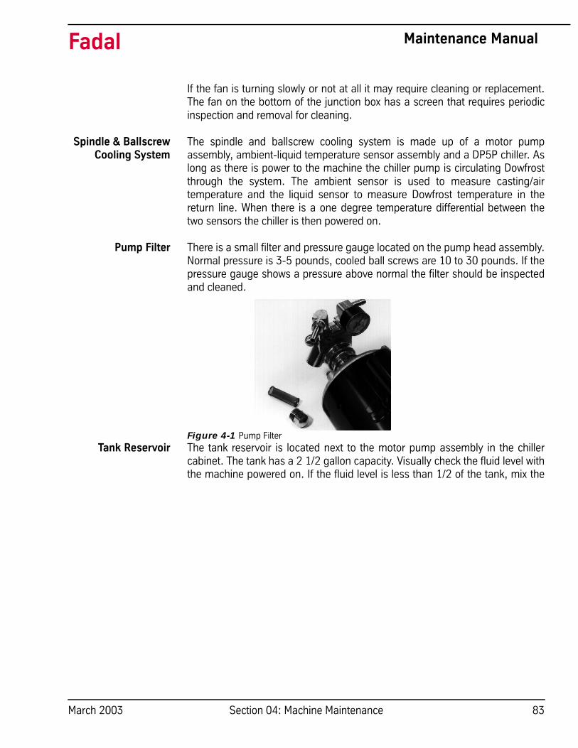
Pump Filter There is a small filter and pressure gauge located on the pump head assembly.Normal pressure is 3-5 pounds, cooled ball screws are 10 to 30 pounds. If thepressure gauge shows a pressure above normal the filter should be inspectedand cleaned.
Figure 4-1 Pump FilterTank Reservoir The tank reservoir is located next to the motor pump assembly in the chiller
cabinet. The tank has a 2 1/2 gallon capacity. Visually check the fluid level withthe machine powered on. If the fluid level is less than 1/2 of the tank, mix the
March 2003 Section 04: Machine Maintenance 83

Fadal Maintenance Manual
Dowfrost to a 50:50 solution, with deionized water, or sodium free distilledwater and fill to no more than 3/4 full.
Figure 4-2 Tank Reservoir
Source for Dowfrost:GOLDENWEST LUBRICANTS1816 POTRERO AVE.SOUTH EL MONTE, CA 91733(626) 443 - 3441(800) 540 - 5823
Do not accept any substitutes for DOWFROST!
PressureThe cooling system should maintain a constant pressure of 3 to 5 psi onmachines with 400 I.P.M. rapid or 10 to 30 psi with 700 I.P.M. rapid.If the pressure rises, the following conditions may exist:
• clogged pump filter; • pinched oil lines; • clogged cross tubes (only on 400 I.P.M. machines equipped with
cooled ball screws).
If the machine is losing pressure and the Dowfrost level keeps dropping, thefollowing conditions may exist:
• the O-ring that seals the ball screw cross tubes is leaking;• there is a hole in one of the lines.
84 Section 04: Machine Maintenance March 2003

Fadal Maintenance Manual
Fuses, Heaters, & Relays
SEE SECTION 18: Fuses, Heaters, Parameters
Fluids
Auger Cleaning and Freeing Chips from the Auger Chip Removal SystemPrior to cleaning or removing jammed material from the Auger or its exit tube.
1) Shut down the VMC by disconnecting the main switch in the back. It isimperative to use OSHA approved Lock Out – Tag Out procedures to powerdown the VMC.
Figure 4-3 Lock Out-Tag Out
WARNINGChips from the machining process are extremely sharp. Do not attempt toremove these materials with bare hands.
Table 1: Fluids
RESERVOIR FILL WITH
Waylube CASTROL MAGNA BD68SHELL TONNA 68V
or MOBIL VACTRA #2
Spindle Cooling System DOWFROST CLEAR(Mixed 50/50 with de-ionized water or sodium
free distilled water)
Rotary Tables MOBIL GEAR 626
Hydraulic Hi/Low MOBIL DTE HEAVY MEDIUM
Hydraulic Brake HYDRAULIC OIL 32
!
March 2003 Section 04: Machine Maintenance 85
Fadal Maintenance Manual
WARNINGDo not remove material while the machine is operating or in the EmergencyStop mode.
Chip Removal from the Machine InteriorRemove the side panels, open front doors, and remove the material from theAuger. Wear heavy leather gloves and use a tool, such as pliers, whenremoving material between the sheet metal and the auger.
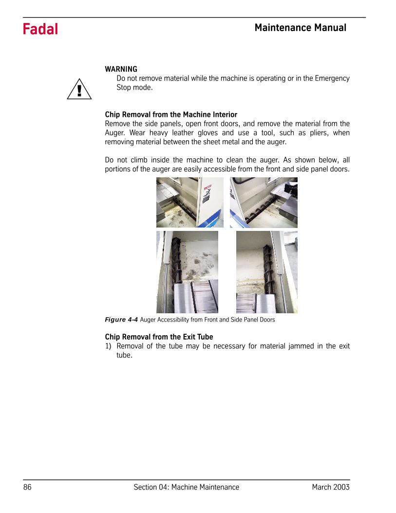
Do not climb inside the machine to clean the auger. As shown below, allportions of the auger are easily accessible from the front and side panel doors.
Figure 4-4 Auger Accessibility from Front and Side Panel Doors
Chip Removal from the Exit Tube1) Removal of the tube may be necessary for material jammed in the exit
tube.
!
86 Section 04: Machine Maintenance March 2003

Fadal Maintenance Manual
2) Remove 6 hex bolts and washers from auger exit tube connection to thesheetmetal housing.
Figure 4-5 Remove Hex Bolts and Washers from Auger Exit Tube
3) Wear heavy leather gloves and use a tool such as pliers when removingjammed material from the auger exit tube. Remove using a heavy steel rod(for hard to reach area in the mid-section of the tube) or pliers.
4) Reattach the auger exit tube to the sheet metal housing.
Dual Arm ToolChanger
The causes of abnormal wear and fractures will be apparent when the toolchanger is used without lubricant. It is very important to grease all movingparts of the tool changer at least once a week.
LubricantThe lubricant should be changed annually, or when it has become visiblydeteriorated. The recommended lubricant is SAE 90-140, approximately 1.3gallons.
GreaseGrease should be spread once a week in the following locations:1) The claws of the tool changing arm unit.
2) The tip of the release pin of the tool changing arm unit.
Cleaning1) Remove the chip powder from around the proximity switch inducing box.
2) Remove the chip powder from around the inverted moving body of the toolpot.
3) The tool changing mechanism must be cleaned frequently to preventexcess build up of chip powder.
March 2003 Section 04: Machine Maintenance 87

Fadal Maintenance Manual
InspectionCheck the parts of the tool falling mechanism regularly and, check for greaseon the sliding base of the tool falling mechanism and the sliding base of thepull rod. Check the parts of the tool pots and tool discs for tightness and overallcondition.
ScheduledMaintenance
for Dual Arm ToolChanger
The maintenance schedule is based on machine usage of eight hours a day,five days a week.
Daily Maintenance Perform the following daily:
1) Cleaning
a. Remove the chips and debris surrounding the proximity switchinducing block.
b. Remove the chips and debris that have accumulated on theinverted moving body of the tool pot.
c. Clear the tool changing mechanism of all debris before any opera-tion.
2) Inspection:
a. Check the parts of the tool falling mechanism for damage andwear. Add grease to the sliding base of the tool falling mechanismand the pull rod.
b. Check the parts of the tool pots, tool discs, and snap rings fordamage and tightness.
Weekly MaintenancePerform the following weekly:
1) Greasing:
a. Grease the claws of the tool changing arm unit.b. Grease the tip of the release pin of the tool changing unit.
Miscellaneous MaintenancePerform the following as necessary:
Change the lubricant annually or as needed. The recommended lubricant isSAE 90-140. The Dual Arm Tool Changer uses approximately 5 liters (1.3gallons).
88 Section 04: Machine Maintenance March 2003

Fadal Maintenance Manual
Calibration of VMCs using the Renishaw laser
Scope This qualification procedure applies to all Fadal VMCs calibrated using theRenishaw Laser and software.
ReferenceDocumentation
Renishaw Laser Measurement System – Current Version – User Manual
Materials andEquipment
• PC Loaded with Renishaw Software and PC10 Plug-in card.• Renishaw ML10 Laser• Renishaw Interferometer• Renishaw Reflector• Temperature Sensor ‘Magnetic’• Temperature Sensor ‘Mechanical’• Laser Tripod
Safety andEnvironmental
Always use caution when working around machinery. Wear proper protectiveclothing and wear safety glasses at all times.
Although the laser used for this measurement is safe to use, it is never a goodidea to look at a “Laser beam” with an unprotected eye. Take care to avoid anunmanaged or unshielded beam, which could strike a bystander.
Definitions Laser Calibration process – The process of obtaining deviations from astandard and using these values to correct a standard via software.
Calibration Measurement – the final calibration measurement after the surveycompensation data has been entered into the controller. This is verification thatthe survey compensation data has corrected the axis to the laser standard.
Survey – Laser measurement to obtain deviation data “to survey” which will beused to enter compensation values into the controller.
Responsibilities Fadal Machining Centers and Quality have responsibility for the test procedure.Managers and Supervisors have responsibility for following this test procedurewhere its use is required.
Procedure This procedure will measure unidirectional axis travel in reference to acalibrated laser. Deviations are generated which are loaded into the VMCcontroller software. The software will correct for the mechanical deviationsimproving the accuracy of axis travel. This procedure is designed as aproduction qualification and machine calibration procedure. It covers only onetype of laser measurement. Refer to the current Renishaw manual for other
March 2003 Section 04: Machine Maintenance 89

Fadal Maintenance Manual
laser methods if required. It may be used for re-calibration of a machine afterservice or re-build. It may also be used for re-calibration of a machine afterservice or re-build
The procedure is written for a technician that has had training both with theRenishaw manual and on the job… Therefore, only trained technicians shouldbe performing this calibration procedure.
For further detail on Laser set-up, refer to the set-up section of the currentRenishaw manual.
CAUTION: Laser could cause severe eye damage, do not point laser outside or mirrorrange nor look directly into.
Standard FadalCnc88hs
Axis to be Calibrated and Configuration
There are three axis (X, Y and Z) which may be calibrated using this procedureand two configurations one using the motor encoder the other using theoptional scale box. The table below directs which axis and configuration to useduring production testing:
* ONLY if Z-Calibrate Option is ordered.
The reason both Encoder and Scale calibration measurements are completed,when the scale option is purchased, is to provide a backup calibration to thecustomer in the event the scales need to be disabled.
Documentation Place copies of all axis surveys and calibrations in the Fadal Machine AssemblyCheckout Record.Place copies of the final axis surveys in customer documentation pocket of theVMC.
No Scale Option X/Y Scale Option Z Scale Option
Survey at Encoder X Y Z* X Y X Y Z
Survey with Scale X Y X Y Z
Calibrate with Encoder X Y X Y X Y Z
Calibrate with Scale X Y X Y Z
90 Section 04: Machine Maintenance March 2003
Fadal Maintenance Manual
CalibrationRequirements and
Limits
VMCs over compensated via software...this is not considered calibrated. Thelimits for proper calibration are (100%pas).
Maximum Target to Target Compensation < 0.0003”
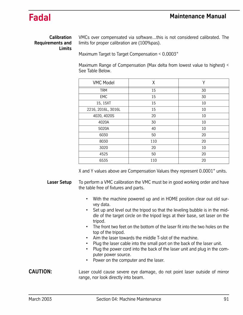
Maximum Range of Compensation (Max delta from lowest value to highest) <See Table Below.
X and Y values above are Compensation Values they represent 0.0001” units.
Laser Setup To perform a VMC calibration the VMC must be in good working order and havethe table free of fixtures and parts.
• With the machine powered up and in HOME position clear out old sur-vey data.
• Set up and level out the tripod so that the leveling bubble is in the mid-dle of the target circle on the tripod legs at their base, set laser on thetripod.
• The front two feet on the bottom of the laser fit into the two holes on thetop of the tripod.
• Aim the laser towards the middle T-slot of the machine.• Plug the laser cable into the small port on the back of the laser unit.• Plug the power cord into the back of the laser unit and plug in the com-
puter power source. • Power on the computer and the laser.
CAUTION: Laser could cause severe eye damage, do not point laser outside of mirrorrange, nor look directly into beam.
VMC Model X Y
TRM 15 30
EMC 15 30
15, 15XT 15 10
2216, 2016L, 3016L 15 10
4020, 4020S 20 10
4020A 30 10
5020A 40 10
6030 50 20
8030 110 20
3020 20 10
4525 50 20
6535 110 20
March 2003 Section 04: Machine Maintenance 91

Fadal Maintenance Manual
Note: The laser will require 15 minutes to warm up.
• Plug the RS232 cable into the RS232 serial port on the back of the sidewiring cabinet of the VMC.
• Plug the laser cable into the small port on the back of the laser unit.
92 Section 04: Machine Maintenance March 2003

Fadal Maintenance Manual
• Install beam splitter into spindle. There are two arrows on the beamsplitter for calibrating the X–axis, the arrows should be pointing downthe X-axis and away from the column. The mirror “must be attached” tothe front of the beam splitter. For calibrating the Y-axis, the arrows go inthe same direction as the X-axis, but attach the mirror to the left of thebeam splitter.
• Install mirror unit in the middle T-slot on the table.
• Jog Z-axis head down so the bottom of the beam splitter and the mirroron the table are horizontally even.
• Tighten down the mirror on the table.
• Install the first temperature sensor on the inside of the door away fromany draft, the second sensor, which is a magnetic temperature sensoris to be placed in the middle T- Slot, middle of the table.
Aligning the laser • When lining up the laser beam the beam must go into the beam splitter
from the laser at 3:00 and come out of the splitter at 9:00 for X-axis.
• With the X-axis at its negative end, line up the beams superimposed oneach other. Do this by jogging the head and adjusting the mirrors fromside to side. Be sure that the mirror and the beam splitter are com-pletely parallel with each other.
• Once the beams superimpose, jog the X-axis to its positive limit.
• Line up the beams on the target of the laser superimposed. (This maytake a while with a lot of adjusting.)
• Use the three adjusters to correct the lasers position, always level first,then rotate (unit turning CW or CCW), and last translate (laser up anddown). This is the proper way for fast and accurate alignment of thelaser.
• Once the beams superimpose, then turn the dial on the front of thelaser one turn in the clockwise direction. This should leave the targetposition to open, to let the laser receive the beam.
• After laser set up check the computer screen to see if the signal meteris completely green, if so then you are ready to go. (If the signal meteris not green, then adjust using steps above).
March 2003 Section 04: Machine Maintenance 93

Fadal Maintenance Manual
Download Survey For Fadal Control use the following survey downloading procedure:
§ Run Survey Download off computer desktop [REN2FAD.EXE]
§ On Fadal Control and at Enter Next Command, type CD,6
§ Follow program instructions and enter appropriate data.
Note: Program will move into axis calibration.
Axis Calibration Data CaptureTarget Sequence – LinearNumber of runs – 1 for survey 2 for calibrationSelect Direction – Unidirectional
Amend Title Information – (Do as Prompted) VMC Type Serial Number Location – (Same as “Auto Target Generate” Target) Title – Encoder or Scale, and Survey or Calibration
Escape
ALT P = Changes the DatumF2 = Datum’s the LaserAlt – = Changes the sign from negative to positive and vice versa.
Run program on CPU Select axis (x, y, or z) Select length of axis Agree or disagree Push F2 to datum the computerStart Data CapturePush Auto and run the rest of the program on the VMCWhen prompted, hit enter and slidehold the program – SETCS and send axis tohome position
Save data – Save and Name Computer files as follows: [Axis] [E,S or C] [The last 6 serial number digits] E = Encoder Survey, S = Scale Survey, C = Calibration Axis = X, Yor Z
For a SN: 01200010111, an example is: XE010111 or YS010111
94 Section 04: Machine Maintenance March 2003

Fadal Maintenance Manual
Analyze
Surveys – (Error Comp Table)Absolute ValueProduce Error Comp TableGraph – (Renishaw Analysis)
Copies of survey and calibration placed in machine (electrical cabinet pocket)and document book or jacket.
Exit Application
March 2003 Section 04: Machine Maintenance 95

Fadal Maintenance Manual
Sample output froma laser measurement
system.
RENISHAW CALIBRATION INTERFEROMETER SYSTEMERROR COMPENSATION TABLE
MACHINE VMC 3020 SERIAL No: XXXXDATE: XXXXX By:Axis: Y AXIS Location: –9Title: Type Combined table with backlashvalueCompensation type AbsoluteCompensation resolution 0.0001 inReference position –9.0000 inCompensation start –9.0000 inCompensation end 10.0000 inCompensation spacing 1.0000 in
Backlash value 0.0000 in Compensation valuesNo. Axis position Combined (in) (0.0001 in)
1 –9.00000 0 2 –8.00000 –1 3 –7.00000 –2 4 –6.00000 –2 5 –5.00000 –3 6 –4.00000 –3 7 –3.00000 –4 8 –2.00000 –4 9 –1.00000 –4 10 0.00000 –4 11 1.00000 –4 12 2.00000 –4 13 3.00000 –4 14 4.00000 –5 15 5.00000 –4 16 6.00000 –5 17 7.00000 –5 18 8.00000 –6 19 9.00000 –6 20 10.00000 –7
96 Section 04: Machine Maintenance March 2003

Fadal Maintenance Manual
This partial view of COMP_VALUES_y shows the survey values from the abovefile. Notice that there are three pointers in the brackets. Out of those three, themiddle number has the same meaning as the position No. in the file above.
N50 $AA_ENC_COMP [_ENC_NR, 1, AX2] = - 0.0000 corresponds to No. 1and N75 $AA_ENC_COMP [_ENC_NR, 6, AX2] = - 0.0003 corresponds to No.6 in the table.
N75 $AA_ENC_COMP[_ENC_NR, 6, AX2] = - 0.0003N35 $MA_ENC_COMP_ENABLE[_ENC_NR, AX2] =0N40 NEWCONFstopre;-----BEGINNING—OF—SURVEY----------
N45 $AA_ENC_COMP[_ENC_NR,0,AX2]=-0.0000N50 $AA_ENC_COMP[_ENC_NR,1,AX2]=-0.0000N55 $AA_ENC_COMP[_ENC_NR,2,AX2]=-0.0001N60 $AA_ENC_COMP[_ENC_NR,3,AX2]=-0.0002N65 $AA_ENC_COMP[_ENC_NR,4,AX2]=-0.0002N70 $AA_ENC_COMP[_ENC_NR,5,AX2]=-0.0003N75 $AA_ENC_COMP[_ENC_NR,6,AX2]=-0.0003N80 $AA_ENC_COMP[_ENC_NR,7,AX2]=-0.0004N85 $AA_ENC_COMP[_ENC_NR,8,AX2]=-0.0004N90 $AA_ENC_COMP[_ENC_NR,9,AX2]=-0.0004N95 $AA_ENC_COMP[_ENC_NR,10,AX2]=-0.0004N100 $AA_ENC_COMP[_ENC_NR,11,AX2]=-0.0004N105 $AA_ENC_COMP[_ENC_NR,12,AX2]=-0.0004N110 $AA_ENC_COMP[_ENC_NR,13,AX2]=-0.0004N115 $AA_ENC_COMP[_ENC_NR,14,AX2]=-0.0005N120 $AA_ENC_COMP[_ENC_NR,15,AX2]=-0.0004N125 $AA_ENC_COMP[_ENC_NR,16,AX2]=-0.0005N130 $AA_ENC_COMP[_ENC_NR,17,AX2]=-0.0005N135 $AA_ENC_COMP[_ENC_NR,18,AX2]=-0.0006N140 $AA_ENC_COMP[_ENC_NR,19,AX2]=-0.0006N145 $AA_ENC_COMP[_ENC_NR,20,AX2]=-0.0007
;-------END--OF--SURVEY----------------
N150 $AA_ENC_COMP_STEP[_ENC_NR,AX2]=1
March 2003 Section 04: Machine Maintenance 97

Fadal Maintenance Manual
Laser Shut Down • When finished with entire calibration procedure for all axes Press F5and exit application, then exit to DOS.
• Turn off laser and move dial one notch until target shows.• Unplug laser cable and RS232 cable.• Power down and Unplug computer.• Store all equipment and clean up workstation.
98 Section 04: Machine Maintenance March 2003

Fadal Maintenance Manual
Pallet Changer/Hydro Sweep™
Each Part Cycle1) Make certain that HydroSweep unit is cycled before every Pallet Exchange.
Use an M20 in the program to make it automatic. Frequent washing out ofchips prevents them from building up into difficult-to-remove piles.
2) Blow away any chips that may lodge underneath Pallet in Hydraulic Armgroove.
Daily Maintenance1) Put both Pallets away onto stand. Put tool in spindle. Wash down interior
with coolant hose nozzle, using care to keep splash away from AutomaticTool Changer, Head assembly, or any wiring connections.
2) Wash out HydroSweep drum, clearing any chips from inside. Inspectbehind HydroSweep Ram for any stray chips blocking return slot.
3) Clean chips from trough behind Table and Saddle, and on Sliding Doors.
4) Guard, and inspect between front Y-axis way cover and front of machine forchip buildup.
5) Remove screen/tank cover over fluid tank, and clean screen protectingpumps.
6) Using tool, check for any chip buildup in tank ahead of screen.
7) Check tank reservoir fluid level, and refill as necessary.
8) Check Waylube level, refill with Castrol Magna BD68, Shell Tonna V68, orMobil Vactra #2.
9) Check for air pressure. Single regulators should be set for 80PSI. Dualregulators should be set at 80PSI on the left gauge, and 90-100PSImaximum on the right gauge.
10) Move X-axis to either side, and flip over outer X-axis way cover. Inspect forchip buildup, and clean. Check for waylube presence on both X-axis ways.Inspect Z-axis and Y-axis as well.
11) Check pressures/vacuum on Coolant-Thru pump filter and replace filter, ifnecessary.
Weekly Maintenance1) Check Hydraulic Fluid level for Pallet Clamp on top of machine. Use Mobil
DTE Heavy Medium.
2) Remove Hydraulic Arm pump cover, and inspect Hydraulic Arm system,refilling fluid if necessary.
March 2003 Section 04: Machine Maintenance 99

Fadal Maintenance Manual
3) Check Hydraulic Arm chain tension by push/pull on arm.
4) Remove Head Cover, and inspect fluid lines for Hi/Lo Idler assembly,refilling, if necessary.
5) Remove all tools from tool changer, and clean out any chip buildup. Whenreturning tools to ATC, inspect retention ring tension on tool holders forexcessive looseness, replacing rings, if necessary.
6) Disconnect front Y-axis way cover from saddle, and check for chip buildup.
7) Inspect under Y-axis motor for chips, and clear out drain ports under Y-axisways nearest the column.
Monthly Maintenance1) Carefully remove pallets, and grease rail bearings, using care not to
damage lip seals.
2) Remove spindle motor top filter cover, and inspect filter. Replace, ifnecessary.
3) Inspect Pallet Roller latch system for both Pallets on stand.
4) Inspect all HydroSweep nozzles for chip clogging.
5) Check Pallet Lift Door for smooth operation.
6) Inspect Chiller cabinet for low fluid in container, should be 1/2 to 3/4 full.
7) Inspect Chiller recirculation pump filter, and clean as needed.
8) Blow air into top of Chiller louvers to clear out dirt collecting on condenser.
9) At bottom of rear cabinet, remove fan filter screen and clean.
10) Inspect front door rollers, tightening as necessary.
11) Check door interlock system for proper operation.
12) Remove head cover and inspect belts, and check for any Coolant-thrusystem leaks.
13) Inspect all cables, hoses, and tubing for looseness, or damage.
100 Section 04: Machine Maintenance March 2003

Fadal Maintenance Manual
HydroSweep™ Only Each Part Cycle1) Make certain that HydroSweep unit is cycled before every part change, or
run at least 20 minutes per hour run time. Use an M20 in the program tomake it automatic. Frequent washing out of chips prevents them frombuilding up into difficult-to-remove piles, and clears drum from chipbuildup.
2) Clean away any chips that may lodge in rear trough at bottom of Y-axissliding tray.
Daily Maintenance1) Wash down interior with coolant hose nozzle, using care to keep splash
away from Automatic Tool Changer, Head assembly, or any wiringconnections.
2) Wash out HydroSweep drum, clearing any chips from inside. Inspectbehind HydroSweep Ram for any stray chips blocking return slot.
3) Clean chips from trough behind Table and Saddle, and on Sliding Guard,and behind Sliding Guard near Y-axis ballscrew, and inspect between frontY-axis way cover and front of machine for chip buildup.
4) Remove screen/tank cover over fluid tank, and clean screen protectingpumps.
5) Using shovel, check for any chip buildup in tank ahead of screen.
6) Check tank reservoir fluid level, and refill as necessary, using only coolantwith anti-foam inhibitors.
7) Check Waylube level, refill with Castrol Magna BD68, Shell Tonna V68, orMobil Vactra #2.
8) Check for air pressure. Single regulators should be set for 80PSI. Dualregulators should be set at 80PSI on the left gauge, and 90-100PSImaximum on the right gauge.
9) Move X-axis to either side, and flip over outer X-axis way cover. Inspect forchip buildup, and clean. Check for waylube presence on both X-axis ways.Inspect Z-axis and Y-axis as well.
10) Check pressures/vacuum on Coolant-Thru pump filter and replace filter, ifnecessary.
March 2003 Section 04: Machine Maintenance 101

Fadal Maintenance Manual
Weekly Maintenance1) Remove Head Cover, and inspect fluid lines for Hi/Lo Idler assembly,
refilling, if necessary.
2) Remove all tools from tool changer, and clean out any chip buildup found.When returning tools to ATC, inspect retention ring tension on tool holdersfor excessive looseness, replacing rings, if necessary.
3) Disconnect front Y-axis way cover from saddle, and check for chip buildup.
4) Inspect under Y-axis motor for chips, and clear out drain ports under Y-axisways nearest the column.
Monthly Maintenance1) Remove spindle motor top filter cover, and inspect filter. Replace, if
necessary.
2) Inspect all HydroSweep nozzles for chip clogging.
3) Inspect Chiller cabinet for low fluid in container, should be 1/2 to 3/4 full.
4) Inspect Chiller recirculation pump filter, and clean as needed.
5) Blow air into top of Chiller louvers to clear out dirt collecting on condenser.
6) At bottom of rear cabinet, remove fan filter screen and clean.
7) Inspect front door rollers, tightening as necessary.
8) Check door interlock system for proper operation.
9) Remove head cover and inspect belts, and check for any Coolant-thrusystem leaks.
10) Inspect all cables, hoses, and tubing for looseness, or damage.
The above maintenance procedures may be performed by customer'smaintenance crew.
6-Month Planned MaintenanceThis should be performed by the Fadal Planned Maintenance Crew semi-annually.
102 Section 04: Machine Maintenance March 2003

Fadal Maintenance Manual
Tests for CE Safeguards on Fadal Machines
These tests should be done when machine is first installed and after servicingwhen any components are replaced.
1) Power on machine but do not cold start.
Start spindle. (Press Shift-Spindle on)• Spindle will not start OR• Press Emergency Stop; spindle must stop. • Immediately release Emergency Stop; spindle does not start.
2) Cold start machine.
Start spindle. (Press Shift-Spindle on) • Press Emergency Stop; spindle must stop. • Immediately release Emergency Stop; spindle shall not start, VMC
remains in emergency stop.• Repeat test in Auto, MDI, and Jog modes.
3) Start spindle. (Press Shift-Spindle on)
• Open front door; spindle must stop. • Try to restart spindle; spindle does not start with doors open.• Check LED on 2000-1 board; it should be on.• Check contactor for spindle; contacts should be out. (There may be a 5
to 10 second delay between the opening of the door and the release ofthe contactor. This allows a controlled stop).
4) Close doors.
• Repeat test with left side panel.• Repeat test with right side panel.
5) Do a TC,1 with doors open.
• Z-axis does not rise if doors are open.• close doors and execute TC,1.
6) With doors open press manual (ending TC,1).
• Z-axis does not move unless doors are closed.
March 2003 Section 04: Machine Maintenance 103

Fadal Maintenance Manual
Daily & Weekly Safety Tests for CE Safety CircuitsTo ensure proper functioning of safety circuits, the following tests should beperformed on a regular basis.
DailyThe Door Interlock Monitor will be on the 1310-0C board if the machine has anauger, or on the 2000-1A board. If the machine does not have an auger and is not CE, there will be no DoorInterlock Monitor.
Door Interlock Monitor Daily Test for 2000-1A or 1310-0C1) Close all doors. Make sure VMC is not in emergency stop.
2) Start spindle at slow speed.
3) Open front door.
Spindle should stop immediately (fully stopped from any speed in less than5 seconds). Five to ten seconds after the door is opened you should hearthe spindle contactor open. (The five to ten second delay allows the spindleto come to a controlled stop.)
4) Close front door. Spindle contactor will immediately reenergize.
DailyFront Door Lock Daily Test for 2030-OA1) Close all doors. Make sure machine is not in emergency stop.
2) Open front door. You may be able to hear the spindle contactor open, if nota second person will be needed to watch the contactor.
3) Close front door. You may be able to hear the contactor close, if not see 2above.
4) Start spindle. Attempt to open front door. Front door should be locked.
5) Stop spindle. There should be a delay of 1 to 5 seconds after the spindlecomes to a complete stop before the door unlocks. (This delay can beadjusted from 1 to 5 seconds with R22.)
6) In either automatic or manual mode command a tool change. Attempt toopen the door. Front door should be locked while turret is moving towardspindle or while dual arm tool changer arm is in motion.
Dual Arm Tool Changer (1330) Daily TestNo daily test.
104 Section 04: Machine Maintenance March 2003

Fadal Maintenance Manual
Pallet Changer (1100-3A) Daily TestNo daily test.
WeeklyThe Door Interlock Monitor will be on the 1310-0C board if the machine has anauger, or on the 2000-1A board. If the machine does not have an auger and is not CE, there will be no DoorInterlock Monitor.
Door Interlock Monitor (2000-1A) Weekly Test1) Close all doors. Make sure VMC is not in emergency stop.
2) Open cabinet containing Door Interlock Board (2000-1A) and examineLEDs and relays on the 2000-1A board.
• Red door LEDs should be off.• Green door LEDs should be on.• Estop relay (K3) should be on (LED lit).• Output relay for spindle contactor (K2) should be on (LED lit).
3) Press Emergency Stop switch.
• Estop relay should go off immediately.• Output relay should go off after 5 to 10 seconds.
4) Release Emergency Stop switch and clear emergency stop condition bypressing Jog.
5) Open front door.
• Front door red LED should be on.• Green door LEDs should be off.• Spindle contactor should release after 5 to 10 seconds.
6) Close front door and open left side door.
• Left door red LED should be on.• Green door LEDs should be off.• Spindle contactor should release after 5 to 10 seconds.
7) Close left side door and open right side door.
• Right door red LED should be on.• Green door LEDs should be off.• Spindle contactor should release after 5 to 10 seconds.
March 2003 Section 04: Machine Maintenance 105

Fadal Maintenance Manual
WeeklyDoor Interlock Monitor Weekly Test for 2000-1 B or -1 C
1) Close all doors. Make sure VMC is not in emergency stop.
2) Open cabinet containing Door Interlock Board (2000-1 B or -1 C) andexamine LEDs and relays on the 2000-1 B or -1 C board.
• Red door LEDs should be off. • Yellow door LEDs should be off. Green "Doors Closed" LED should be
on. • Red Slidehold LEDs should be off. • Estop relay (K3) should be on (LED lit). • Green "Spindle Enable" LED should be on. • "Spindle" relay for spindle contactor (K2) should be on (LED lit).
3) Press Emergency Stop switch.
• Estop relay should go off immediately. • Spindle Enable LED and Spindle relay should go off after 5 to 10 sec-
onds. • Spindle contactor should then release.
4) Release Emergency Stop switch and clear emergency stop condition bypressing Jog.
5) Open front door.
• Front door red LEDs should be on. • Green "Doors Closed" LED should be off. • The yellow LED for the front door should flash at the instant the door is
opened. • Spindle Enable LED and Spindle relay should go off and Spindle con-
tactor should release after 5 to 10 seconds.
6) Close front door and open left side door.
• Left door red LEDs should be on. • Green "Doors Closed" LED should be off. • Yellow door LED should flash at the instant the one door is closed and
when the other door is opened. • Spindle Enable LED and Spindle relay should go off and Spindle con-
tactor should release after 5 to 10 seconds.
7) Close left side door and open right side door.
• Right door red LEDs should be on.
106 Section 04: Machine Maintenance March 2003

Fadal Maintenance Manual
• Green "Doors Closed" LED should be off. • Yellow door LED should flash at the instants the one door is closed and
when the other door is opened. • Spindle Enable LED and Spindle relay should go off and Spindle con-
tactor should release after 5 to 10 seconds.
Door Interlock Monitor on Auger Board (1310-0C) Weekly Test1) Close all doors. Make sure VMC is not in emergency stop.
2) Open cabinet containing Auger Board (1310-0A) and examine LEDs andrelays on the 1310-0A board.
• Red door LEDs should be off.• Green door LEDs should be on.• Estop relay (K7) should be on (LED lit).• Spindle relay for spindle contactor (K5) should be on (LED lit).• Heart LED should be blinking.
3) Press Emergency Stop switch.
• Estop relay should go off immediately.• Heart LED should be off.• Spindle relay should go off after 5 to 10 seconds.
4) Release Emergency Stop switch and clear emergency stop condition bypressing Jog.
5) Open front door.
• Front door red LED should be on.• Green door LEDs should be off.• Heart LED should be off.• Spindle contactor should release after 5 to 10 seconds.
6) Close front door and open left side door.
• Left door red LED should be on.• Green door LEDs should be off.• Spindle contactor should release after 5 to 10 seconds.
7) Close left side door and open right side door.
• Right door red LED should be on.• Green door LEDs should be off.• Heart LED should be off.• Spindle contactor should release after 5 to 10 seconds.
March 2003 Section 04: Machine Maintenance 107

Fadal Maintenance Manual
Weekly:Front Door Lock Weekly Test for 2030-OA1) Close all doors.
2) Open cabinet containing Front Door Lock Board (2030-OA) and examineLEDs and relays on the 2030-OA board.
• Power LED should be on. • Green "Unlock Door" LED should be on. • Green "Doors Closed" LED should be on. • LED on K6 and K7 should be on. • No other LEDs should be on.
3) Open front door.
• Green "Doors Closed" LED should be off. • LED on K7 should be off. • Other LEDs should be unchanged.
4) Close front door and start spindle.
• Attempt to open front door. • Front door should be locked. • "Spindle Rotating", "Spindle ON", "VMC Motion", and "Unlock Delay"
LEDs should be on. • "Unlock Door" LED should be off. • LED on K6 should be off.
5) Stop SPINDLE.
• There should be a delay of 1 to 5 seconds after the spindle comes to acomplete stop before the door unlocks.
6) If there is a pallet changer start a pallet change.
• Attempt to open front door. Front door should be locked. • "Pallet Motion", "VMC Motion", and "Unlock Delay" LEDs should be on.• "Unlock LED should be off. • LED on K6 should be off.
Dual Arm Tool Changer (1330) Weekly Test1) Make sure the VMC is not in emergency stop, that the spindle is off, and
that no tool change is in progress.
2) Open cabinet containing the Dual Arm Tool Changer Control Board 1330-0and examine the LEDs and relays.
108 Section 04: Machine Maintenance March 2003

Fadal Maintenance Manual
• The LED (D16) for the contactor SSR should be off.• The E-stop relay (K5) should be energized (LED on, contact indicator
showing).• The E-stop Signal relay (K6) should be energized (LED on, contact indi-
cator showing).• The Drawbar and Arm Interlock relay (K7) should be energized (LED on,
contact indicator showing).• The Arm Power relay (K8) should be energized (LED on, contact indica-
tor showing).
3) Start spindle and examine LEDs and relays on 1330-0.
• The Drawbar and Arm Interlock relay (K7) should not be energized (LEDoff, contact indicator not showing).
• The Arm Power relay (K8) should not be energized (LED off, contactindicator not showing).
4) Stop spindle. Press Emergency Stop. Examine LEDs on 1330-0.
• The E-stop relay (K5) should not be energized (LED off, contact indica-tor not showing).
• The Drawbar and Arm Interlock relay (K7) should not be energized (LEDoff, contact indicator not showing).
• The Arm Power relay (K8) should not be energized (LED off, contactindicator not showing).
Pallet Changer (1100-3A) Weekly Test1) Make sure there are no obstructions to the light curtain.
• The green LED on the Light Curtain receiver should be on.• The red LED on the Light Curtain receiver should be off.
2) Break the light curtain path with your hand.
• The green LED on the Light Curtain receiver should be off.• The red LED on the Light Curtain receiver should be on.• Red LEDs on the receiver will also show the beams that are being
obstructed.
3) Make sure there are no obstructions to the light curtain. Open the cabinetcontaining Pallet Change Power Distribution board (1100-3A) and examinethe LEDs on the 1100-3A.
• The green LEDs (D8 and D9) on the 1100-3A board should be on.• The red LED (D7) on the 1100-3A board should be off.
March 2003 Section 04: Machine Maintenance 109

Fadal Maintenance Manual
4) Obstruct the light curtain (a towel over one of the mirrors will do this) andobserve the LEDs on the 1100-3A.
• The green LEDs (D8 and D9) on the 1100-3A board will be off.• The red LED (D7) on the 1100-3A board will be on.
5) Start a pallet change and while the pallet is in motion obstruct the lightcurtain. The pallet change should stop immediately and a message shouldappear on the monitor requiring Start to be pressed to continue.
Zero-Out MemoryProcedure
Note: Everything in memory will be erased! Store desired programs &data to disk
1) Send machine to COLD START:
• Type SETCS < ENTER >.• Type HO <ENTER>.• Press START.
2) Display and record the BACKLASH settings on the second page of thisinstruction sheet (Settings) in the spaces provided:
• Type BL <ENTER>. Record the displayed values.
3) Display and record the PARAMETER settings on the second page of thisinstruction sheet (Settings) in the spaces provided:
NOTE: Some parameters appear ONLY in Format 1 or in Format 2, but NOT INBOTH FORMATS.
• Type SETP <ENTER>. Record the displayed values.• Type P <ENTER> to display the second page of settings. Record the displayedvalues.• Type P <ENTER> to display the third, page of settings. Record the displayedvalues.
4) After all BACKLASH and PARAMETER settings have been recorded, zeromemory:
• Press <MANUAL> to get to ENTER NEXT COMMAND.• Type DI < ENTER >.
110 Section 04: Machine Maintenance March 2003

Fadal Maintenance Manual
• Type GOA3000 <ENTER> to display the Diagnostics Menu.• Press spacebar to get to Page 2 of the Diagnostic Menu, and select option 5 -ZERO MEMORY.• Answer "Y" (type Y) to both questions the control asks. Memory is reset.
NOTE: If you are replacing a module(s), now is the time to power down themachine,replace the module(s), and power up ---- then proceed directly to STEP 5below.
• Select option 2 - START CNC. This will take the control back to ENTER NEXTCOMMAND.
5) Restore PARAMETER values as needed:
NOTE: The control will ask for BACKLASH values, but the PARAMETER valuesmust be checked first.
• Type SETP <ENTER> to check and, if needed, re-enter PARAMETER settings -page 1.• Type P <ENTER> to check and, if needed, re-enter PARAMETER settings -page 2.• Type P <ENTER> to check and, if needed, re-enter PARAMETER settings -page 3.
6) Restore BACKLASH values:
• Power off the machine, wait 15 seconds, power on the machine, COLDSTART.• Enter the BACKLASH values previously recorded as follows: for X axis BL,1,value 1, value2, value3 < ENTER > for Y axis BL,2,valuel,value2,value3 <ENTER> for Z axis BL,3,value < ENTER > for A axis BL,4,value <ENTER> for B axis BL,S,value <ENTER>
7) Load the programs and offsets back into the machine. This procedure isnow complete.
March 2003 Section 04: Machine Maintenance 111

Fadal Maintenance Manual
Zero-Out MemorySettings Last Home Position X___________ Y___________ Z____________
Backlash Settings
X-axis Backlash ___________ ,___________,___________Y-axis Backlash ___________ ,___________,___________Z-axis Backlash___________A-axis Backlash___________B-axis Backlash___________
Parameter Settings
Format:___________Baud Rate:__________Spindle After M6:_______Axes:___________Travel:___________Pendant:___________Default:___________A-AxisRatio:__________M60/A-Axis Brake:___________Default:___________B-AxisRatio:___________M60B-AxisBrake:___________Default:Tool Changer Cap:IMM Fixed Cycle:RPM Factor:Spindle Type:Orientation Factor:
Parameter settings - Page 2
Default:___________M3:_______M7:_______3 Phase>5%Low:___________Pu Format:__________N-words Ordered:__________Tool Table:___________Crc Mode:___________Binary Buffers:___________High Torque:__________Spindle Off:___________Turret Factor:___________CMD Menu:___________Pallet:___________Gain:___________Ramp:___________Aspect:___________Tilers:___________Overload:___________
Parameter Settings - Page 3
Screw:___________Imp:___________Xyz Ramp:___________Z Tap Gain:___________Vector:___________Axis Display:___________Auto Brake:___________A-pallet:___________ B-pallet:___________5-Axis Head:___________G0 Detail:___________Feedback:___________
112 Section 04: Machine Maintenance March 2003