Secoroc Y26, Y19A rock drills - narzedziawiertnicze.pl · Thank you for selecting the Secoroc hand...
20
Secoroc Y26, Y19A rock drills Operator’s instructions Spare parts list
Transcript of Secoroc Y26, Y19A rock drills - narzedziawiertnicze.pl · Thank you for selecting the Secoroc hand...

Secoroc Y26, Y19A rock drillsOperator’s instructions Spare parts list

2
Table of contentsIntroduction �����������������������������������������������������������������3Safety instructions ������������������������������������������������������3Scope of application ����������������������������������������������������8Specification ���������������������������������������������������������������������������������������� 8
Operation ���������������������������������������������������������������������9Using the rock drill for the first time ������������������������������������������������� 9
Preparations before starting �������������������������������������������������������������� 9
Drill steel ���������������������������������������������������������������������������������������������� 9
Fitting and removing the drill steel ������������������������������������������������� 10
Before fitting the drill steel ��������������������������������������������������������������� 10
Fitting the drill steel �������������������������������������������������������������������������� 10
Removing the drill steel ������������������������������������������������������������������� 10
Controls ��������������������������������������������������������������������������������������������� 10
Throttle lever ������������������������������������������������������������������������������������� 10
Extra blowing lever ��������������������������������������������������������������������������� 10
Drilling ������������������������������������������������������������������������������������������������11
Starting the rock drill �������������������������������������������������������������������������11
Checking the lubrication ��������������������������������������������������������������������11
Stopping the rock drill �����������������������������������������������������������������������11
Blow-cleaning the drill hole ��������������������������������������������������������������11
When you have finished drilling ������������������������������������������������������11
Maintenance ���������������������������������������������������������������������������������������11
Once a shift (after 8 hours of operation) ������������������������������������������11
Once a week (after 40 hours of operation) ������������������������������������� 12
Once a month (after 200 hours of operation) ��������������������������������� 12
Selection of spare parts�������������������������������������������������������������������� 12
Storage ���������������������������������������������������������������������������������������������� 12
Scrapping and waste disposal ��������������������������������������������������������� 12
Noise and vibration declaration statement ������������ ����������������������� 12
CE Declaration of Conformity ���������������������������������������������������������� 13
Trouble shooting ��������������������������������������������������������14Spare parts list and exploded drawing �������������������16
ForewordThank you for selecting the Secoroc hand held rock drill Y26/Y19A�
These instructions were developed to help you get the best per-formance and productivity from the use of your new rock drill�
Please refer to them also for the correct maintenance of the rock drill�
3
IntroductionThank you for choosing a product from Epiroc� We have a strong global sales and service network, consisting of customer centers and distributors worldwide� Our experts are highly trained profes-sionals with extensive product knowledge and application experi-ence� In all corners of the world, we can offer product support and expertise to ensure that our customers can work at maximum efficiency at all times�
For more information please visit: epiroc�com
About the Safety and operating instructionsThe aim of the instructions is to provide you with knowledge of how to use the rock drill in an efficient, safe way� The instructions also give you advice and tell you how to perform regular mainte-nance on the rock drill� Before using the rock drill for the first time you must read these instructions carefully and understand all of them�
Safety instructionsTo reduce the risk of serious injury or death to yourself or others, read and understand the Safety and operating instruction before installing, operating, repairing, maintaining, or changing acces-sories on the machine� Post this Safety and operating instruction at work locations, provide copies to employees, and make sure that everyone reads the Safety and operating instruction before operating or servicing the machine� In addition, the operator or the operator's employer must assess the specific risks that may be present as a result of each use of the machine�
Safety signal wordsThe safety signal words Danger, Warning and Caution have the following meanings:
Indicates a hazardous situation which, if not avoided, will result in death or serious injury�
DANGER
Indicates a hazardous situation which, if not avoided, could result in death or serious injury�
WARNING
Indicates a hazardous situation which, if not avoided, could result in minor or moderate injury�
CAUTION
Personal precautions and qualificationsOnly qualified and trained persons may operate or maintain the machine� They must be physically able to handle the bulk, weight, and power of the tool� Always use your common sense and good judgement�
Personal protective equipment
Always use approved protective equipment� Operators and all other persons in the working area must wear protective equip-ment, including at a minimum:
• Protective helmet
• Hearing protection
• Impact resistant eye protection with side protection
• Respiratory protection when appropriate
• Protective gloves
• Proper protective boots
• Appropriate work overall or similar clothing (not loose-fitting) that covers your arms and legs�
4
Drugs, alcohol or medication�
WARNING
Drugs, alcohol or medication may impair your judgment and pow-ers of concentration� Poor reactions and incorrect assessments can lead to severe accidents or death�
• Never use the machine when you are tired or under the influ-ence of drugs, alcohol or medication�
• No person who is under the influence of drugs, alcohol or medi-cation may operate the machine�
Installation, precaution
Whipping air hose�
DANGER
A compressed air hose that comes loose can lash around and cause personal injury or death� To reduce this risk:
• Check that the compressed air hose and the connections are not damaged, replace if necessary�
• Check that all compressed air connections are properly attached�
• Never carry a pneumatic machine by the air hose�
• Never attempt to disconnect a compressed air hose that is pres-surized� First switch off the compressed air at the compressor and then bleed the machine by activating the start and stop device�
• Do not use quick disconnect couplings at tool inlet�
Use hardened steel (or material with comparable shock resist-ance) threaded hose fittings�
• Whenever universal twist couplings (claw couplings) are used, we recommend that lock pins are installed and whipcheck safety cables are used to safeguard against possible hose to tool and hose to hose connection failure�
Ejected insertion tool�
WARNING
If the tool retainer on the machine is not in a locked position, the inserted tool can be ejected with force, which can cause personal injury�
• Never start the machine while changing the insertion tool�
• Before changing the insertion tool or accessories, stop the machine, switch off the power supply and bleed the machine by activating the start and stop device�
• Never point the inserted tool at yourself or anyone else�
• Make sure that the insertion tool is fully inserted and the tool retainer is in a locked position before the machine is started�
• Check the locking function by pulling the inserted tool outwards forcefully�
Moving or slipping insertion tool�
WARNING
An incorrect dimension of the inserted tool’s shank can result in that the inserted tool is lost or is slipping out during operation� Risk of severe injury or crushed hands and fingers�
• Check that the insertion tool has the shank length and dimen-sions that the machine is intended for�
• Never use an insertion tool without a collar�
Operation, precautions
Explosion hazard�
DANGER
If a warm insertion tool comes into contact with explosives, an explosion could occur� During operation with certain materials as well as use of certain materials in machine parts, sparks and igni-tion can occur� Explosions will lead to severe injuries or death�
• Never operate the machine in any explosive environment�
• Never use the machine near flammable materials, fumes or dust�
• Make sure that there are no undetected sources of gas or explo-sives�
• Never drill in an old hole
If a warm insertion tool comes into contact with explosives, an explosion could occur� During operation with certain materials as well as use of certain materials in machine parts, sparks and igni-tion can occur� Explosions will lead to severe injuries or death�
• Never operate the machine in any explosive environment�
• Never use the machine near flammable materials, fumes or dust�
• Make sure that there are no undetected sources of gas or explo-sives�
• Never drill in an old hole�
Unexpected movements�
WARNING
The inserted tool is exposed to heavy strains when the machine is used� The inserted tool may break due to fatigue after a certain amount of use� If the inserted tool breaks or gets stuck, there may be sudden and unexpected movement that can cause injuries� Furthermore, losing your balance or slipping may cause injury�
• Make sure that you always keep a stable position with your feet as far apart as your shoulder width, and keeping a balanced body weight�
• Always inspect the equipment prior to use� Never use the equip-ment if you suspect that it is damaged�
• Make sure that the handles are clean and free of grease and oil�
• Keep your feet away from the inserted tool�
• Stand firmly and always hold on to the machine with both hands�
• Never drill in an old hole�
5
• Never start the machine when it is lying on the ground�
• Never ‘ride’ on the machine with one leg over the handle�
• Never strike or abuse the equipment�
• Check regularly for wear on the insertion tool, and check whether there are any signs of damage or visible cracks�
• Pay attention and look at what you are doing
Stalling hazard�
WARNING
If the insertion tool gets caught during operation, the whole machine will start to rotate if you lose your grip on it� This unex-pected rotation of the entire machine may cause serious injury or death�
• Stand firmly and always hold onto the machine with both hands�
• Make sure that the handle or handles are clean and free from grease and oil�
• Never drill in an old hole�
Trapping hazard�
WARNING
There is risk of neck ware, hair, gloves and clothes getting dragged into or caught by a rotating insertion tool or accessories� This may cause choking, scalping, lacerations or death� To reduce the risk:
• Never grab or touch a rotating drill steel�
• Avoid wearing clothing, neck ware or gloves that may get caught�
• Cover long hair with a hair net
Always make sure that the rock drilling tools are in good con-dition before use�
CAUTION
Dust and fume hazard�
WARNING
Dusts and/or fumes generated or dispersed when using the machine may cause serious and permanent respiratory disease, illness, or other bodily injury (for example, silicosis or other irre-versible lung disease that can be fatal, cancer, birth defects, and/or skin inflammation)� Some dusts and fumes created by drilling, breaking, hammering, sawing, grinding and other construction activities contain substances known to the State of California and other authorities to cause respiratory disease, cancer, birth defects, or other reproductive harm� Some examples of such substances are:
• Crystalline silica, cement, and other masonry products�
• Arsenic and chromium from chemically-treated rubber�
• Lead from lead-based paints�
Dust and fumes in the air can be invisible to the naked eye, so do not rely on eye sight to determine if there is dust or fumes in the air� To reduce the risk of exposure to dust and fumes, do all of the following:
• Perform site-specific risk assessment� The risk assessment should include dust and fumes created by the use of the machine and the potential for disturbing existing dust�
• Use proper engineering controls to minimize the amount of dust and fumes in the air and to minimize build-up on equipment, surfaces, clothing, and body parts� Examples of controls include: exhaust ventilation and dust collection systems, water sprays, and wet drilling� Control dusts and fumes at the source where pos-sible� Make sure that controls are properly installed, maintained and correctly used�
• Wear, maintain and correctly use respiratory protection as in-structed by your employer and as required by occupational health and safety regulations� The respiratory protection must be effec-tive for the type of substance at issue (and if applicable, approved by relevant governmental authority)�
• Work in a well ventilated area�
• If the machine has an exhaust, direct the exhaust so as to reduce disturbance of dust in a dust filled environment�
• Operate and maintain the machine as recommended in the oper-ating and safety instructions
• Select, maintain and replace consumables/ working tools/ other accessory as recommended in the operating and safety instruc-tions� Incorrect selection or lack of maintenance of consumables/inserted tools/ other accessories may cause an unnecessary increase in dust or fumes�
• Wear washable or disposable protective clothes at the worksite, and shower and change into clean clothes before leaving the worksite to reduce exposure of dust and fumes to yourself, other persons, cars, homes, and other areas�
• Avoid eating, drinking, and using tobacco products in areas where there is dust or fumes�
• Wash your hands and face thoroughly as soon as possible upon leaving the exposure area, and always before eating, drinking, us-ing tobacco products, or making contact with other persons�
• Comply with all applicable laws and regulations, including oc-cupational health and safety regulations�
• Participate in air monitoring, medical examination programs, and health and safety training programs provided by your em-ployer or trade organizations and in accordance with occupational health and safety regulations and recommendations� Consult with physicians experienced with relevant occupational medicine�
• Work with your employer and trade organization to reduce dust and fume exposure at the worksite and to reduce the risks� Effec-tive health and safety programs, policies and procedures for pro-tecting workers and others against harmful exposure to dust and fumes should be established and implemented based on advice from health and safety experts� Consult with experts�
• Residues of hazardous substances on the machine can be a risk� Before undertaking any maintenance on the machine clean it thoroughly�
6
Projectiles�
WARNING
Failure of the work piece, of accessories, or even of the machine itself may generate high velocity projectiles� During operating, splinters or other particles from the working material may be-come projectiles and cause personal injury by striking the opera-tor or other persons� To reduce these risk:
• Use approved personal protective equipment and safety helmet, including impact resistant eye protection with side protection�
• Make sure that no unauthorised persons trespass into the work-ing zone�
• Keep the workplace free from foreign objects�
• Ensure that the work piece is securely fixed�
Splinters hazard�
WARNING
Using the insertion tool as a hand struck tool can result in splin-ters hitting the operator and can cause personal injury�
• Never use an insertion tool as a hand struck tool� They are spe-cifically designed and heat-treated to be used only in a machine�
Slipping, tripping and falling hazards�
WARNING
There is a risk of slipping or tripping or falling, for example trip-ping on the hoses or on other objects� Slipping or tripping or falling can cause injury� To reduce this risk:
• Always make sure that no hose or other object is in your way or in any other person's way�
• Always make sure you are in a stable position with your feet as far apart as your shoulders width and keeping a balanced body weight�
Motion hazards�
WARNING
When using the machine to perform work-related activities, you may experience discomfort in the hands, arms, shoulders, neck, or other parts of the body�
• Adopt a comfortable posture whilst maintaining secure footing and avoiding awkward off-balanced postures�
• Changing posture during extended tasks may help avoid dis-comfort and fatigue�
• In case of persistent or recurring symptoms, consult a qualified health professional�
Vibration hazards�
WARNING
Normal and proper use of the machine exposes the operator to vibration� Regular and frequent exposure to vibration may cause, contribute to, or aggravate injury or disorders to the operator’s fingers, hands, wrists, arms, shoulders and/or nerves and blood supply or other body parts, including debilitating and/or perma-nent injuries or disorders that may develop gradually over peri-ods of weeks, months, or years� Such injuries or disorders may include damage to the blood circulatory system, damage to the nervous system, damage to joints, and possibly damage to other body structures� If numbness, persistent recurring discomfort, burning sensation, stiffness, throbbing, tingling, pain, clumsiness, weakened grip, whitening of the skin, or other symptoms occur at any time, when operating the machine or when not operating the machine, stop operating the machine, tell your employer and seek medical attention� Continued use of the machine after the occur-rence of any such symptom may increase the risk of symptoms becoming more severe and/or permanent� Operate and maintain the machine as recommended in these instructions, to prevent an unnecessary increase in vibration� The following may help to reduce exposure to vibration for the operator:
• Let the tool do the job� Use a minimum hand grip consistent with proper control and safe operation�
• If the machine has vibration absorbing handles, keep them in a central position, avoid pressing the handles into the end stops�
• When the percussion mechanism is activated, the only body contact with the machine you should have are your hands on the handle or handles� Avoid any other contact, for example support-ing any part of the body against the machine or leaning onto the machine trying to increase the feed force� It is also important not to keep the start and stop device engaged while extracting the tool from the broken work surface�
• Make sure that the inserted tool is well-maintained (including sharpness, if a cutting tool), not worn out, and of the proper size� Insertion tools that are not well-maintained, or that are worn out, or that are not of the proper size result in longer time to complete a task (and a longer period of exposure to vibration) and may result in or contribute to higher levels of vibration exposure�
• Immediately stop working if the machine suddenly starts to vibrate strongly� Before resuming the work, find and remove the cause of the increased vibrations�
• Never grab, hold or touch the inserted tool when using the machine�
• Participate in health surveillance or monitoring, medical exams and training programs offered by your employer and when re-quired by law�
• When working in cold conditions wear warm clothing and keep hands warm and dry�
• The exhaust air is strongly chilled and shall not make contact with the operator� Always direct the exhaust air away from hands and body�
See the ”Noise and vibration declaration statement” for the machine, including the declared vibration values� This information can be found at the end of these Safety and operating instruc-tions�
• Comply with the recommended air-pressure when operating the machine� Either higher or lower air-pressure has the potential of resulting in higher levels of vibration�
7
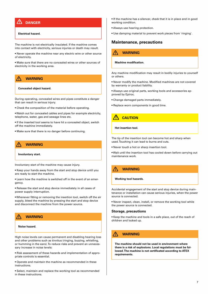
Electrical hazard�
DANGER
The machine is not electrically insulated� If the machine comes into contact with electricity, serious injuries or death may result�
• Never operate the machine near any electric wire or other source of electricity�
• Make sure that there are no concealed wires or other sources of electricity in the working area�
Concealed object hazard�
WARNING
During operating, concealed wires and pipes constitute a danger that can result in serious injury�
• Check the composition of the material before operating�
• Watch out for concealed cables and pipes for example electricity, telephone, water, gas and sewage lines etc�
• If the inserted tool seems to have hit a concealed object, switch off the machine immediately�
• Make sure that there is no danger before continuing�
Involuntary start�
WARNING
Involuntary start of the machine may cause injury�
• Keep your hands away from the start and stop device until you are ready to start the machine�
• Learn how the machine is switched off in the event of an emer-gency�
• Release the start and stop device immediately in all cases of power supply interruption�
• Whenever fitting or removing the insertion tool, switch off the air supply, bleed the machine by pressing the start and stop device and disconnect the machine from the power source�
Noise hazard�
WARNING
High noise levels can cause permanent and disabling hearing loss and other problems such as tinnitus (ringing, buzzing, whistling, or humming in the ears)� To reduce risks and prevent an unneces-sary increase in noise levels:
• Risk assessment of these hazards and implementation of appro-priate controls is essential�
• Operate and maintain the machine as recommended in these instructions�
• Select, maintain and replace the working tool as recommended in these instructions�
• If the machine has a silencer, check that it is in place and in good working condition�
• Always use hearing protection�
• Use damping material to prevent work pieces from 'ringing'�
Maintenance, precautions
Machine modification�
WARNING
Any machine modification may result in bodily injuries to yourself or others�
• Never modify the machine� Modified machines are not covered by warranty or product liability�
• Always use original parts, working tools and accessories ap-proved by Epiroc�
• Change damaged parts immediately�
• Replace worn components in good time�
Hot insertion tool�
CAUTION
The tip of the insertion tool can become hot and sharp when used� Touching it can lead to burns and cuts�
• Never touch a hot or sharp insertion tool�
• Wait until the insertion tool has cooled down before carrying out maintenance work�
Working tool hazards�
WARNING
Accidental engagement of the start and stop device during main-tenance or installation can cause serious injuries, when the power source is connected�
• Never inspect, clean, install, or remove the working tool while the power source is connected�
Storage, precautions
• Keep the machine and tools in a safe place, out of the reach of children and locked up�
The machine should not be used in environment where there is a risk of explosions� Local regulations must be fol-lowed� The machine is not certificated according to ATEX requirements�
WARNING
8
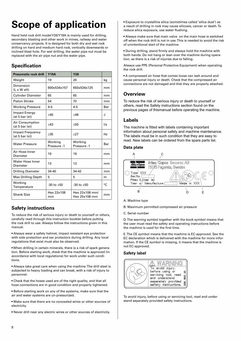
Scope of applicationHand held rock drill model Y26/Y19A is mainly used for drilling, secondary blasting and other work in mines, railway and water conservancy projects� It is designed for both dry and wet rock drilling on hard and medium hard rock, vertically downwards or inclined blast hole� For wet drilling, the water pipe nut must be replaced with the air pipe nut and the water pipe�
Specification
Pneumatic rock drill Y19A Y26
Weight 19 26 kg
Dimension (L x W xH)
600x534x157 650x534x125 mm
Cylinder Diameter 65 65 mm
Piston Stroke 54 70 mm
Working Pressure 4-5 4-5 Bar
Impact Energy (at 5 bar (e))
≥40 ≥48 J
Air Consumption (at 5 bar (e))
≤43 ≤50 l/s
Impact Frequency (at 5 bar (e))
≥35 ≥27 Hz
Water PressureWorking Pressure -1
Working Pressure -1
Bar
Air Hose Inner Diameter
19 19 mm
Water Hose Inner Diameter
13 13 mm
Drilling Diameter 34-40 34-42 mm
Max Drilling Depth 5 5 m
Working Temperature
-30 to +50 -30 to +50 °C
Shank SizeHex 22x108 mm
Hex 22x108 mm/ Hex 25x108 mm
mm
Safety instructionsTo reduce the risk of serious injury or death to yourself or others, carefully read through this instruction booklet before putting the rock drill to use� Always follow the instructions given in this manual�
• Always wear a safety helmet, impact resistant eye protection with side protection and ear protectors during drilling� Any local regulations that exist must also be observed�
• When drilling in certain minerals, there is a risk of spark genera-tion� Before starting work, check that the machine is approved (in accordance with local regulations) for work under such condi-tions�
• Always take great care when using the machine� The drill steel is subjected to heavy loading and can break, with a risk of injury to personnel�
• Check that the hoses used are of the right quality, and that all hose connections are in good condition and properly tightened�
• Before starting work on any of the systems, make sure that the air and water systems are un-pressurized�
• Make sure that there are no concealed wires or other sources of electricity�
• Never drill near any electric wires or other sources of electricity�
• Exposure to crystalline silica (sometimes called ‘silica dust’) as a result of drilling in rock may cause silicosis, cancer or death� To reduce silica exposure, use water flushing�
• Always make sure that main valve on the main hose is switched off when the rock drill is not in use� This is needed to avoid the risk of unintentional start of the machine�
• During drilling, stand firmly and always hold the machine with both hands� Do not hang or lean over the machine during opera-tion, as there is a risk of injuries due to falling�
Always use PPE (Personal Protective Equipment) when operating the rock drill�
• A compressed air hose that comes loose can lash around and cause personal injury or death� Check that the compressed air connections are not damaged and that they are properly attached�
OverviewTo reduce the risk of serious injury or death to yourself or others, read the Safety instructions section found on the previous pages of thismanual before operating the machine.
LabelsThe machine is fitted with labels containing important information about personal safety and machine maintenance. The labels must be in such condition that they are easy to read. New labels can be ordered from the spare parts list.
Data plate
A
B
C
D E
A� Machine type
B� Maximum permitted compressed air pressure
C� Serial number
D� The warning symbol together with the book symbol means that the user must read the safety and operating instructions before the machine is used for the first time�
E� The CE symbol means that the machine is EC-approved� See the EC declaration which is delivered with the machine for more infor-mation� If the CE symbol is missing, it means that the machine is not EC-approved�
Safety label
A
B
C
D E
To avoid injury, before using or servicing tool, read and under-stand separately provided safety instructions�

9
OperationUsing the rock drill for the first timeWhen the rock drill arrives from the factory, the inside of the tool is coated with heavy oil to prevent corrosion�
After unpacking and installing the tool, pour a small amount of lu-brication oil into the air connection and operate the tool on partial throttle to clean the interior� Follow this immediately with a liberal amount of air tool oil�
The rock drill is lubricated with oil mixed with compressed air, which is taken to the parts that need continuous lubrication� Oil is metered into the compressed air from the lubricator located on top of the cylinder�
Preparations before starting1� Check the drilling equipment
• Check that all of the drilling equipment is in good working order�
• Check that the impact surface of the drill steel shank is flat with no signs of wear�
• Make sure that the air inlet and exhaust ports are free from obstructions�
• Check that the flushing holes in the drill steel and drill bit are not blocked and that the flushing air/water flows through without obstruction�
• Ensure that the fittings are tight and leak-proof�
A compressed air hose that comes loose can lash around and cause personal injury or death� Check that the com-pressed air connections are not damaged and that they are properly attached�
WARNING
2� Blow out the air hose
Every day before using the drill, blow out the air hose to clear it from accumulated dirt and moisture�
3� Check the lubrication oil level
• Fill the lubricator (located on top of the cylinder) with oil if nec-essary� The rock drill is lubricated with oil mixed with compressed air, which is taken to the parts that need continuous lubrication� Oil is metered into the compressed air�
• Use Atlas Copco Rock Drill AIR-OIL as a lubricant�
Lubricant recommendation
Use a mineral-based air tool oil
Ambient temperature ºC Viscosity grade (ISO 3448)
-30 to 0 ISO VG 32-68
-10 to +20 ISO VG 68-100
+10 to +50 ISO VG 100-150
4� Air/water pressure and hose dimensions
Air pressure
Ensure that the compressor can deliver the required air pressure of 5 bar at the machine�
• High pressure (>6�3 bar) causes rough operation and damage�
• Low pressure (<4 bar) results in a slow drilling speed�
Water pressure
Set the water preassure to around 3 bar� Maximum water pres-sure is 1 bar less than the air pressure� For example if the air pres-sure is 5 bar, the water pressure must be below 4 bar to prevent water entering the impact mechanism�
Air hose dimensions
The air hose diameter must be no less than 25 mm� The inner diameter of connection nipples and hoses must be no less than 19 mm� The ideal overall air hose length is less than 30 m�
Water hose dimensions
The water hose inner diameter must be no less than ½”�
5� Prevent freezing
In low ambient temperatures, ice can form in the machine� This can be avoided if the water in the compressed air is removed� This can be done by equipping the air lines with water separators and drainage points for water condensate�
If the rock drill ices up, it must not be heated to melt the ice� Let the ice thaw at room temperature�
Do not pour methylated spirits or similar substances into the rock drill, as they will interfere with the lubrication and lead to increased wear�
6� Conversion to water flushing
The Y26 is normally used for dry drilling� When wet drilling is re-quired, remove the air pipe nut (spare parts list, No� 53)� Replace it with the water pipe nut (spare parts list, No� 2) and the water pipe (spare parts list, No� 1)� Connect the water hose to the water pipe and turn on the water supply�
Drill steel
Ejected insertion tool�
WARNING
If the tool retainer on the machine is not in a locked position, the inserted tool can be ejected with force, which can cause personal injury�
• Before changing the insertion tool, stop the machine, switch off the compressed air supply and bleed the machine by activating the start and stop device�
Before fitting the insertion tool
Check that the tool shank is of the correct size and length for the chuck used� The shank must be clean and the tool must be in good condition� Shanks which are chipped, rounded, out of square or too hard on the striking end will operate inefficiently and cause premature piston failure� Inspect the drill steel: A dull drill steel will slow down the drilling speed and overstrain the drill mecha-nism� When changing drill steel make sure that the new one is the correct size to follow your previous bore�
Before drilling, check that the flushing hole in the drill steel is not blocked�
• Remove sharp edges from the shank's end face� A rough shank surface will cause premature piston failure�
• Inspect the drill steel: A dull drill steel will slow down the drilling speed and overstrain the drill mechanism� When changing drill steel make sure that the new one is the correct size to follow your previous bore�

10
• Before drilling check that the flushing hole in the drill steel is not blocked�
Hot insertion tool�
CAUTION
The tip of the insertion tool can become hot and sharp when used� Touching it can lead to burns and cuts�
• Never touch a hot or sharp insertion tool�
• Wait until the insertion tool has cooled down before carrying out maintenance work�
Note: Never cool a hot insertion tool in water, it can result in brit-tleness and early failure�
Fitting the drill steel
Whenever fitting the drill steel the following instructions must be observed:
Fitting and removing the drill steelBefore fitting the drill steel
• Check that the drill steel shank is of the correct size and length for the chuck used�
• The shank must be clean and the drill steel must be in good condition�
• The suitable quenching hardness of the shank is HRC48-53� A harder end face will cause piston damage and breakage of the end face of the piston� If the shank face is too soft it will be easily deformed by the piston which will result in difficulty in removing the drill steel�
• The shank end face shall be flat and perpendicular to the axis�
Fitting the drill steel
1� Push the retainer outwards in the direction of the arrow (see picture below), until the front portion of the retainer is able to ac-commodate the drill steel collar�
2� Insert the drill in the chuck�
3� When the drill bottoms, push back the retainer to lock it�
Removing the drill steel
1� Push the retainer outwards in the direction of the arrow until the drill steel collar disengages from the front of the retainer�
2� Pull the drill steel out�
3� Push back the retainer�
ControlsThrottle lever
The rock drill is equipped with a throttle lever for regulating the
compressed air to the percussion mechanism�
A� Stop
B- Slight running
C� Low throttle
D� Medium throttle
E� Full throttle
Extra blowing lever
Start and stop extra blowing using the extra blowing lever� The lever has two positions:
A�Pulling the lever to this position will start extra blowing and stop the machine�
B�Pushing the lever to this position will stop extra blowing and start the machine
Operation
Involuntary start�
WARNING
Involuntary start of the machine may cause injury�
• Keep your hands away from the start and stop device until you are ready to start the machine�
• Learn how the machine is switched off in the event of an emer-gency�
• Stop the machine immediately in all cases of power supply inter-ruption�
DrillingStarting the rock drill
1� Open the main valve for compressed air�
2� Align the rock drill so that the drill steel touches the desired collaring point�

11
3� Move the throttle lever forward a little, which will start water flushing, percussion and rotation�
4� Collar the hole with reduced feed force�
5� Move the throttle lever fully forward once the drill steel has gained a secure footing in the rock�
The start-and-stop device of Pusher Leg Rock Drill Y26A can cause a risk of an unimtentional start� To reduce and avoid causing the risk of unintentional start, the control valve og inlet hose must be switched off while the rock drill is put aside for long time�
Note! Do not bend the drill steel as this will increase wear of the shank bushing and piston� Furthermore, it can also affect drilling efficiency and increase the risk of drill steel breakage�
Stopping the rock drill
Pull the throttle lever backwards, which will stop percussion, rota-tion and flushing water�
Checking the lubrication
The chuck and drill steel shank must always be covered by a film of oil�
Blow-cleaning the drill hole
Whipping air hose�
DANGER
A compressed air hose that comes loose can lash
around and cause personal injury or death
• Check that the compressed air hose and the connections are not damaged�
• Check that all compressed air connections are properly attached�
When blow-cleaning, particles and dirty flushing water can emerge at speed from the drill hole�
CAUTION
• Move to the side and cover your eyes before starting to blow-clean the drill hole�
• Always wear impact resistant eye protection with side protection to avoid injury�
• Make sure that no co-workers are in range when blow-cleaning�
If powerful blow-cleaning of the drill hole is required, turn the ex-tra blowing lever fully backwards, whereupon the rock drill stops� This can be done during drilling� When the drill hole is clean, turn the extra blowing lever forwards again to re-start the rock drill�
When you have finished drilling
Run the rock drill at medium speed when retracting the drill steel from the drilled hole�
Lay down the rock drill on a stone, wooden plank or similar ob-ject, so as to prevent drill cuttings and other foreign matter from entering the chuck�
Turn off the water pressure before the air pressure� Run the rock drill for a few seconds to clean out water and moisture after the water has been shut off�
Always switch off the main control valve on the air inlet hose to prevent unintentional start of the rock drill�
MaintenanceRegular maintenance is a prerequisite for machine safety� Replace damaged and worn components in good time�
Check the machine and drill steel for wear and damage at regular intervals� Do not use a very worn or damaged drill steel�
When cleaning mechanical parts with a solvent, make sure that you comply with current health and safety regulations and ensure that there is sufficient ventilation�
Daily maintenance, regular checking of wearing parts and carrying out repairs in good time prevents breakdowns and increases the service life of the machine�
• Make sure that no foreign matter enters the machine�
Always hose down and wipe clean the rock drill after use�
Once a shift (after 8 hours of operation)
• Check the wear in the chuck bushing� If the wear limit has been exceeded, the drill steel shank will wear more quickly, or become deformed� This will lead to stoppages and increased drill steel consumption�
• Check the tightness of the side bolt nuts� (80 Nm)
• Check the hoses, couplings and controls for leakage and dam-age�
• Check that the rock drill is receiving enough lubrication� Fill the lubricator if necessary�
• Every day before using the drill, blow out the air hose to clear it from accumulated dirt and moisture�
• Drain the water separator (if one is used)�
• Check the air and water pressure� Make sure that the water pres-sure is at least 1 bar lower than the air pressure�
Once a week (after 40 hours of operation)
Carry out a basic check of all functions of the drilling equipment�
Once a month (after 200 hours of operation)
• Send the rock drill to a workshop for inspection� The local operat-ing conditions will determine whether or not this is a suitable interval for overhauling the drill�
• Clean out the water separator (if one is used)
Differences between original parts and pattern partsWhen buying a part, the first thing to do is to verify that the part is an Epiroc part� Most parts can be identified�
Every dayBefore undertaking any maintenance or changing the insertion tool on pneumatic machines, always switch off the air supply and bleed the machine by depressing the start and stop device then disconnect the air hose from the machine�
• Clean and inspect the machine and its functions each day before the work commences�
• Conduct a general inspection for leaks and damage�
• Check that the air inlet nipple is tightened and that the claw coupling is free from damage�
• Check the function of the throttle handle� Make sure that it moves freely up and down�
12
• Check the function of the retainer� Make sure that it locks the drill steel�
• Change damaged parts immediately�
• Replace worn components in good time�
• Check the through bolts of the machine� Make sure that they are tightened�
• If the machine is equipped with a silencer, check for damage�
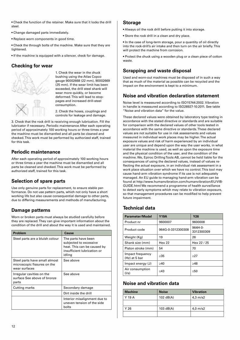
Checking for wear1� Check the wear in the chuck bushing using the Atlas Copco gauge 90002668 (22 mm), 90002669 (25 mm)� If the wear limit has been exceeded, the drill steel shank will wear more quickly, or become deformed� This will lead to stop-pages and increased drill-steel consumption�
2� Check the hoses, couplings and controls for leakage and damage�
3� Check that the rock drill is receiving enough lubrication� Fill the lubricator if necessary� Periodic maintenance After each operating period of approximately 100 working hours or three times a year the machine must be dismantled and all parts be cleaned and checked� This work must be performed by authorized staff, trained for this task�
Periodic maintenanceAfter each operating period of approximately 100 working hours or three times a year the machine must be dismantled and all parts be cleaned and checked� This work must be performed by authorized staff, trained for this task�
Selection of spare partsUse only genuine parts for replacement, to ensure stable per-formance� Do not use pattern parts, which not only have a short working life but also cause consequential damage to other parts, due to differing measurements and methods of manufacturing�
Damage patternsWorn or broken parts must always be studied carefully before they are replaced� They can give important information about the condition of the drill and about the way it is used and maintained�
Problem Cause
Steel parts are a bluish colour The parts have been subjected to excessive heat� This can be caused by insufficient lubrication or idling
Steel parts have small almost microscopic fissures on the wear surfaces
See above
Irregular cavities on the surface See above of bronze parts
See above
Cutting marks Secondary damage
Dirt inside the drill
Interior misalignment due to uneven tension of the side bolts
Storage• Always oil the rock drill before putting it into storage�
• Store the rock drill in a clean and dry place�
• In the case of long-term storage, pour a quantity of oil directly into the rock-drill’s air intake and then turn on the air briefly� This will protect the machine from corrosion�
• Protect the chuck using a wooden plug or a clean piece of cotton waste�
Scrapping and waste disposalUsed and worn-out machines must be disposed of in such a way that as much of the material as possible can be recycled and the impact on the environment is kept to a minimum�
Noise and vibration declaration statementNoise level is meassured according to ISO15744:2002� Vibration in handle is meassured according to ISO28927-10:2011� See table “Noise and vibration data” for the value�
These declared values were obtained by laboratory type testing in accordance with the stated directive or standards and are suitable for comparison with the declared values of other tools tested in accordance with the same directive or standards� These declared values are not suitable for use in risk assessments and values measured in individual work places may be higher� The actual exposure values and risk of harm experienced by an individual user are unique and depend upon the way the user works, in what material the machine is used, as well as upon the exposure time and the physical condition of the user, and the condition of the machine� We, Epiroc Drilling Tools AB, cannot be held liable for the consequences of using the declared values, instead of values re-flecting the actual exposure, in an individual risk assessment in a work place situation over which we have no control� This tool may cause hand-arm vibration syndrome if its use is not adequately managed� An EU guide to managing hand-arm vibration can be found at http://www�humanvibration�com/humanvibration/EU/VIB-GUIDE�html We recommend a programme of health surveillance to detect early symptoms which may relate to vibration exposure, so that management procedures can be modified to help prevent future impairment�
Technical data
Parameter/Model Y19A Y26
Product nr 9600007 9600008
Product code 964G-0-3312300308964H-0-3312300309
Weight (Kg) 19 26
Shank size (mm) Hex 22 Hex 22 / 25
Piston stroke (mm) 54 70
Impact frequency (Hz) at 5 bar
≥35 ≥27
Impact energy (J) ≥40 ≥48
Air consumption (l/s)
≤43 ≤50
Noise and vibration data
Machine Noise Vibration
Y 19 A 102 dB(A) 4,3 m/s2
Y 26 103 dB(A) 4,0 m/s2

13
EC Declaration of Conformity (EC Directive 2006/42/EC)We, Epiroc Drilling Tools AB,hereby declare that the machines listed below conform to the provisions of EC Directive 2006/42/EC (MachineryDirective), and the harmonised standards mentioned below�
Rock Drills Part number Pmax (bar)
Y19A 9600007 6�3
Y26 9600008 6�3
Following harmonised standards were applied:
• EN ISO 11148-5
Technical Documentation authorised representative:
Thomas Greijer, Epiroc Drilling Tools AB, Box 521, SE-737 25 Fagersta, Sweden
Vice president Design and Development:
Jonas Falkestrom, Epiroc Drilling Tools AB, Box 521, SE-737 25 Fagersta, Sweden
14
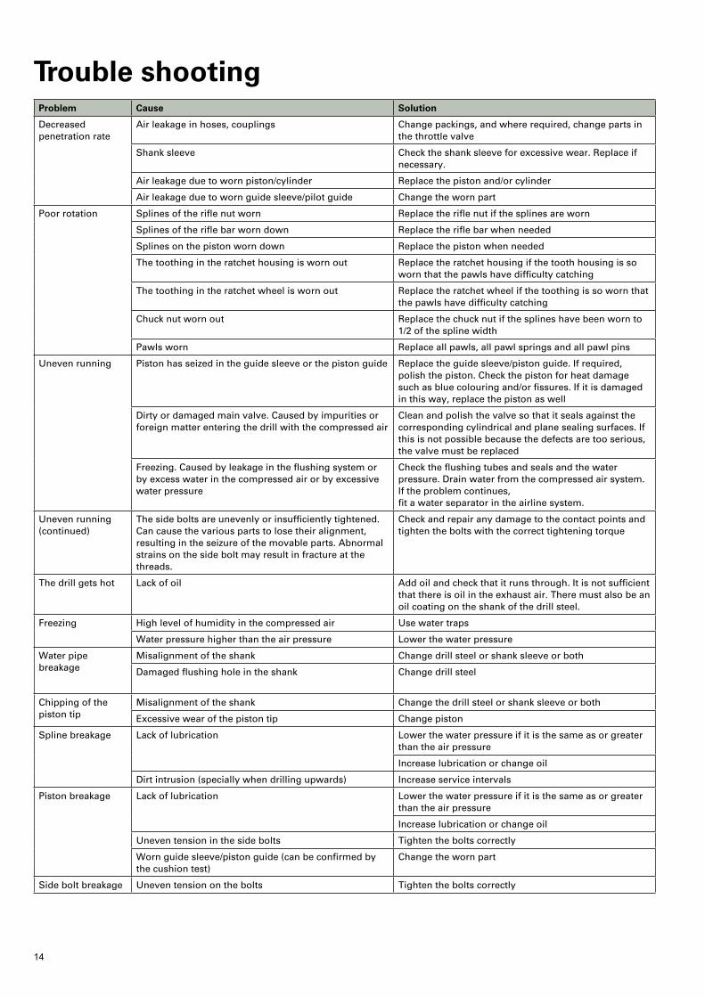
Trouble shootingProblem Cause Solution
Decreased penetration rate
Air leakage in hoses, couplings Change packings, and where required, change parts in the throttle valve
Shank sleeve Check the shank sleeve for excessive wear� Replace if necessary�
Air leakage due to worn piston/cylinder Replace the piston and/or cylinder
Air leakage due to worn guide sleeve/pilot guide Change the worn part
Poor rotation Splines of the rifle nut worn Replace the rifle nut if the splines are worn
Splines of the rifle bar worn down Replace the rifle bar when needed
Splines on the piston worn down Replace the piston when needed
The toothing in the ratchet housing is worn out Replace the ratchet housing if the tooth housing is so worn that the pawls have difficulty catching
The toothing in the ratchet wheel is worn out Replace the ratchet wheel if the toothing is so worn that the pawls have difficulty catching
Chuck nut worn out Replace the chuck nut if the splines have been worn to 1/2 of the spline width
Pawls worn Replace all pawls, all pawl springs and all pawl pins
Uneven running Piston has seized in the guide sleeve or the piston guide Replace the guide sleeve/piston guide� If required, polish the piston� Check the piston for heat damage such as blue colouring and/or fissures� If it is damaged in this way, replace the piston as well
Dirty or damaged main valve� Caused by impurities or foreign matter entering the drill with the compressed air
Clean and polish the valve so that it seals against the corresponding cylindrical and plane sealing surfaces� If this is not possible because the defects are too serious, the valve must be replaced
Freezing� Caused by leakage in the flushing system or by excess water in the compressed air or by excessive water pressure
Check the flushing tubes and seals and the water pressure� Drain water from the compressed air system� If the problem continues, fit a water separator in the airline system�
Uneven running (continued)
The side bolts are unevenly or insufficiently tightened� Can cause the various parts to lose their alignment, resulting in the seizure of the movable parts� Abnormal strains on the side bolt may result in fracture at the threads�
Check and repair any damage to the contact points and tighten the bolts with the correct tightening torque
The drill gets hot Lack of oil Add oil and check that it runs through� It is not sufficient that there is oil in the exhaust air� There must also be an oil coating on the shank of the drill steel�
Freezing High level of humidity in the compressed air Use water traps
Water pressure higher than the air pressure Lower the water pressure
Water pipe breakage
Misalignment of the shank Change drill steel or shank sleeve or both
Damaged flushing hole in the shank Change drill steel
Chipping of the piston tip
Misalignment of the shank Change the drill steel or shank sleeve or both
Excessive wear of the piston tip Change piston
Spline breakage
Lack of lubrication Lower the water pressure if it is the same as or greater than the air pressure
Increase lubrication or change oil
Dirt intrusion (specially when drilling upwards) Increase service intervals
Piston breakage
Lack of lubrication Lower the water pressure if it is the same as or greater than the air pressure
Increase lubrication or change oil
Uneven tension in the side bolts Tighten the bolts correctly
Worn guide sleeve/piston guide (can be confirmed by the cushion test)
Change the worn part
Side bolt breakage Uneven tension on the bolts Tighten the bolts correctly

15
16
1
2
45
6
41
4442
43
46
25
24
39
37
38
36
5026
48
47
7
2728
12
8
10
9
11
13
34
21
51
22
23
49
50
26
48
19
20
32
31
18
32
31
29
30
29
1752
335
4016
15
14
3
45
53
33
9853
125
7 01
20
13.0
8
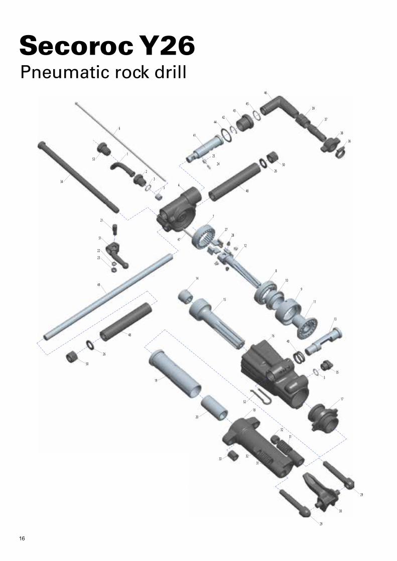
Secoroc Y26 Pneumatic rock drill
Atlas Copco Secoroc ABBox 521, SE-737 25 Fagersta, SwedenPhone +46 223 461 00 E-mail: [email protected]
Ref. Description Qty Prod. No. Product code
1 Water pipe 1 96000216 964H-1-3312310211
2 Water pipe nut 1 96000215 964H-1-3312310210
3 O ring 2 96000502 9605-1-3312310671
4 Back head 1 96000213 964H-1-3312310208
5 Water tube bush 1 96000822 9600-1-3312310019
6 Water/air tube 1 96000217 964H-1-3312310212
7 Ratchet 1 96000805 9600-1-3312310000
8 Valve cover 1 96000197 964H-1-3312310192
9 Valve chest 1 96000198 964H-1-3312310193
10 Valve 1 96000199 964H-1-3312310194
11 Valve sleeve 1 96000200 964H-1-3312310195
12 Rifle bar 1 96000203 964H-1-3312310198
13 Open-close valve 1 96000201 964H-1-3312310196
14 Rifle nut 1 96000814 9600-1-3312310009
15 Piston 1 96000204 964H-1-3312310199
16 Cylinder 1 96000205 964H-1-3312310200
17 Guide sleeve 1 96000206 964H-1-3312310201
18 Front head 1 96000209 964H-1-3312310204
19 Rotation sleeve 1 96000210 964H-1-3312310205
20 Shank bushing (H22) 1 96000168 9605-1-3312310157
20 Shank bushing (H25) 1 96000211 964H-1-3312310206
21 Lock pin 1 96000177 9605-1-3312310167
22 Spring washer 1 96000534 9605-1-3312310716
23 Hexagon thin nut 1 96000524 9605-1-3312310704
24 Spring 1 96000179 9605-1-3312310169
25 Check pin 1 96000180 9605-1-3312310170
26 Small washer 2 96000526 964H-1-3312310706
Ref. Description Qty Prod. No. Product code
27 Ratchet pawl 4 96000166 9605-1-3312310155
28 Conical spring 4 96000167 9605-1-3312310156
29 Retainer bolt 2 96000817 964H-1-3312310012
30 Retainer 1 96000212 964H-1-3312310207
31 Retainer spring 2 96000818 9600-1-3312310013
32 Hexagon lock nut 2 96000531 9605-1-3312310713
33 Hexagon thick nut 2 96000518 9605-1-3312310697
34 Side bolt 2 96000224 964H-1-3312310221
35 Oil plug 1 96000208 964H-1-3312310203
36 Hoop 1 96000539 9605-1-3312310722
37 Conical hose nipple 1 96000222 9605-1-3312310219
38 Wing nut 1 96000221 9605-1-3312310218
39 Pipe sleeve 1 96000223 9605-1-3312310220
40 Spring 1 96000202 964H-1-3312310197
41 Control valve 1 96000220 964H-1-3312310217
42 Retaining ring 1 96000182 9605-1-3312310172
43 Air pipe nut 1 96000823 9600-1-3312310020
44 Pad 1 96000174 9605-1-3312310164
45 Ring seal 2 96000486 9605-1-3312310633
46 Air pipe swivel 1 96000825 9600-1-3312310022
47 Lock pin 1 96000135 9603-1-3312310123
48 Rubber handle 2 96000218 964H-1-3312310213
49 Handle bolt 1 96000219 964H-1-3312310215
50 Hexagon lock nut 1 96000532 964H-1-3312310714
51 Control handle 1 96000307 962A-1-3312310313
52 Open-close handle 1 96000207 964H-1-3312310202
53 Air pipe nut 1 96000214 964H-1-3312310209
1
2
45
6
41
4442
43
46
25
24
39
37
38
36
5026
48
47
7
2728
12
8
10
9
11
13
34
21
51
22
23
49
50
26
48
19
20
32
31
18
32
31
29
30
29
1752
335
4016
15
14
3
45
53
33
9853
125
7 01
20
13.0
8
Secoroc Y26 Pneumatic rock drill
Atlas Copco Secoroc ABBox 521, SE-737 25 Fagersta, SwedenPhone +46 223 461 00 E-mail: [email protected]
Ref. Description Qty Prod. No. Product code
1 Water pipe 1 96000216 964H-1-3312310211
2 Water pipe nut 1 96000215 964H-1-3312310210
3 O ring 2 96000502 9605-1-3312310671
4 Back head 1 96000213 964H-1-3312310208
5 Water tube bush 1 96000822 9600-1-3312310019
6 Water/air tube 1 96000217 964H-1-3312310212
7 Ratchet 1 96000805 9600-1-3312310000
8 Valve cover 1 96000197 964H-1-3312310192
9 Valve chest 1 96000198 964H-1-3312310193
10 Valve 1 96000199 964H-1-3312310194
11 Valve sleeve 1 96000200 964H-1-3312310195
12 Rifle bar 1 96000203 964H-1-3312310198
13 Open-close valve 1 96000201 964H-1-3312310196
14 Rifle nut 1 96000814 9600-1-3312310009
15 Piston 1 96000204 964H-1-3312310199
16 Cylinder 1 96000205 964H-1-3312310200
17 Guide sleeve 1 96000206 964H-1-3312310201
18 Front head 1 96000209 964H-1-3312310204
19 Rotation sleeve 1 96000210 964H-1-3312310205
20 Shank bushing (H22) 1 96000168 9605-1-3312310157
20 Shank bushing (H25) 1 96000211 964H-1-3312310206
21 Lock pin 1 96000177 9605-1-3312310167
22 Spring washer 1 96000534 9605-1-3312310716
23 Hexagon thin nut 1 96000524 9605-1-3312310704
24 Spring 1 96000179 9605-1-3312310169
25 Check pin 1 96000180 9605-1-3312310170
26 Small washer 2 96000526 964H-1-3312310706
Ref. Description Qty Prod. No. Product code
27 Ratchet pawl 4 96000166 9605-1-3312310155
28 Conical spring 4 96000167 9605-1-3312310156
29 Retainer bolt 2 96000817 964H-1-3312310012
30 Retainer 1 96000212 964H-1-3312310207
31 Retainer spring 2 96000818 9600-1-3312310013
32 Hexagon lock nut 2 96000531 9605-1-3312310713
33 Hexagon thick nut 2 96000518 9605-1-3312310697
34 Side bolt 2 96000224 964H-1-3312310221
35 Oil plug 1 96000208 964H-1-3312310203
36 Hoop 1 96000539 9605-1-3312310722
37 Conical hose nipple 1 96000222 9605-1-3312310219
38 Wing nut 1 96000221 9605-1-3312310218
39 Pipe sleeve 1 96000223 9605-1-3312310220
40 Spring 1 96000202 964H-1-3312310197
41 Control valve 1 96000220 964H-1-3312310217
42 Retaining ring 1 96000182 9605-1-3312310172
43 Air pipe nut 1 96000823 9600-1-3312310020
44 Pad 1 96000174 9605-1-3312310164
45 Ring seal 2 96000486 9605-1-3312310633
46 Air pipe swivel 1 96000825 9600-1-3312310022
47 Lock pin 1 96000135 9603-1-3312310123
48 Rubber handle 2 96000218 964H-1-3312310213
49 Handle bolt 1 96000219 964H-1-3312310215
50 Hexagon lock nut 1 96000532 964H-1-3312310714
51 Control handle 1 96000307 962A-1-3312310313
52 Open-close handle 1 96000207 964H-1-3312310202
53 Air pipe nut 1 96000214 964H-1-3312310209

17
1
2
45
6
41
4442
43
46
25
24
39
37
38
36
5026
48
47
7
2728
12
8
10
9
11
13
34
21
51
22
23
49
50
26
48
19
20
32
31
18
32
31
29
30
29
1752
335
4016
15
14
3
45
53
33
9853
125
7 01
20
13.0
8
Secoroc Y26 Pneumatic rock drill
Atlas Copco Secoroc ABBox 521, SE-737 25 Fagersta, SwedenPhone +46 223 461 00 E-mail: [email protected]
Ref. Description Qty Prod. No. Product code
1 Water pipe 1 96000216 964H-1-3312310211
2 Water pipe nut 1 96000215 964H-1-3312310210
3 O ring 2 96000502 9605-1-3312310671
4 Back head 1 96000213 964H-1-3312310208
5 Water tube bush 1 96000822 9600-1-3312310019
6 Water/air tube 1 96000217 964H-1-3312310212
7 Ratchet 1 96000805 9600-1-3312310000
8 Valve cover 1 96000197 964H-1-3312310192
9 Valve chest 1 96000198 964H-1-3312310193
10 Valve 1 96000199 964H-1-3312310194
11 Valve sleeve 1 96000200 964H-1-3312310195
12 Rifle bar 1 96000203 964H-1-3312310198
13 Open-close valve 1 96000201 964H-1-3312310196
14 Rifle nut 1 96000814 9600-1-3312310009
15 Piston 1 96000204 964H-1-3312310199
16 Cylinder 1 96000205 964H-1-3312310200
17 Guide sleeve 1 96000206 964H-1-3312310201
18 Front head 1 96000209 964H-1-3312310204
19 Rotation sleeve 1 96000210 964H-1-3312310205
20 Shank bushing (H22) 1 96000168 9605-1-3312310157
20 Shank bushing (H25) 1 96000211 964H-1-3312310206
21 Lock pin 1 96000177 9605-1-3312310167
22 Spring washer 1 96000534 9605-1-3312310716
23 Hexagon thin nut 1 96000524 9605-1-3312310704
24 Spring 1 96000179 9605-1-3312310169
25 Check pin 1 96000180 9605-1-3312310170
26 Small washer 2 96000526 964H-1-3312310706
Ref. Description Qty Prod. No. Product code
27 Ratchet pawl 4 96000166 9605-1-3312310155
28 Conical spring 4 96000167 9605-1-3312310156
29 Retainer bolt 2 96000817 964H-1-3312310012
30 Retainer 1 96000212 964H-1-3312310207
31 Retainer spring 2 96000818 9600-1-3312310013
32 Hexagon lock nut 2 96000531 9605-1-3312310713
33 Hexagon thick nut 2 96000518 9605-1-3312310697
34 Side bolt 2 96000224 964H-1-3312310221
35 Oil plug 1 96000208 964H-1-3312310203
36 Hoop 1 96000539 9605-1-3312310722
37 Conical hose nipple 1 96000222 9605-1-3312310219
38 Wing nut 1 96000221 9605-1-3312310218
39 Pipe sleeve 1 96000223 9605-1-3312310220
40 Spring 1 96000202 964H-1-3312310197
41 Control valve 1 96000220 964H-1-3312310217
42 Retaining ring 1 96000182 9605-1-3312310172
43 Air pipe nut 1 96000823 9600-1-3312310020
44 Pad 1 96000174 9605-1-3312310164
45 Ring seal 2 96000486 9605-1-3312310633
46 Air pipe swivel 1 96000825 9600-1-3312310022
47 Lock pin 1 96000135 9603-1-3312310123
48 Rubber handle 2 96000218 964H-1-3312310213
49 Handle bolt 1 96000219 964H-1-3312310215
50 Hexagon lock nut 1 96000532 964H-1-3312310714
51 Control handle 1 96000307 962A-1-3312310313
52 Open-close handle 1 96000207 964H-1-3312310202
53 Air pipe nut 1 96000214 964H-1-3312310209

18
1
2
45
6
41
4442
43
46
25
24
39
37
38
36
5026
48
47
7
2728
12
8
10
9
11
13
34
21
51
22
23
49
50
26
48
19
20
32
31
18
32
31
29
30
29
1752
335
4016
15
14
3
45
53
33
9853
125
7 01
20
13.0
8
Secoroc Y26 Pneumatic rock drill
Atlas Copco Secoroc ABBox 521, SE-737 25 Fagersta, SwedenPhone +46 223 461 00 E-mail: [email protected]
Ref. Description Qty Prod. No. Product code
1 Water pipe 1 96000216 964H-1-3312310211
2 Water pipe nut 1 96000215 964H-1-3312310210
3 O ring 2 96000502 9605-1-3312310671
4 Back head 1 96000213 964H-1-3312310208
5 Water tube bush 1 96000822 9600-1-3312310019
6 Water/air tube 1 96000217 964H-1-3312310212
7 Ratchet 1 96000805 9600-1-3312310000
8 Valve cover 1 96000197 964H-1-3312310192
9 Valve chest 1 96000198 964H-1-3312310193
10 Valve 1 96000199 964H-1-3312310194
11 Valve sleeve 1 96000200 964H-1-3312310195
12 Rifle bar 1 96000203 964H-1-3312310198
13 Open-close valve 1 96000201 964H-1-3312310196
14 Rifle nut 1 96000814 9600-1-3312310009
15 Piston 1 96000204 964H-1-3312310199
16 Cylinder 1 96000205 964H-1-3312310200
17 Guide sleeve 1 96000206 964H-1-3312310201
18 Front head 1 96000209 964H-1-3312310204
19 Rotation sleeve 1 96000210 964H-1-3312310205
20 Shank bushing (H22) 1 96000168 9605-1-3312310157
20 Shank bushing (H25) 1 96000211 964H-1-3312310206
21 Lock pin 1 96000177 9605-1-3312310167
22 Spring washer 1 96000534 9605-1-3312310716
23 Hexagon thin nut 1 96000524 9605-1-3312310704
24 Spring 1 96000179 9605-1-3312310169
25 Check pin 1 96000180 9605-1-3312310170
26 Small washer 2 96000526 964H-1-3312310706
Ref. Description Qty Prod. No. Product code
27 Ratchet pawl 4 96000166 9605-1-3312310155
28 Conical spring 4 96000167 9605-1-3312310156
29 Retainer bolt 2 96000817 964H-1-3312310012
30 Retainer 1 96000212 964H-1-3312310207
31 Retainer spring 2 96000818 9600-1-3312310013
32 Hexagon lock nut 2 96000531 9605-1-3312310713
33 Hexagon thick nut 2 96000518 9605-1-3312310697
34 Side bolt 2 96000224 964H-1-3312310221
35 Oil plug 1 96000208 964H-1-3312310203
36 Hoop 1 96000539 9605-1-3312310722
37 Conical hose nipple 1 96000222 9605-1-3312310219
38 Wing nut 1 96000221 9605-1-3312310218
39 Pipe sleeve 1 96000223 9605-1-3312310220
40 Spring 1 96000202 964H-1-3312310197
41 Control valve 1 96000220 964H-1-3312310217
42 Retaining ring 1 96000182 9605-1-3312310172
43 Air pipe nut 1 96000823 9600-1-3312310020
44 Pad 1 96000174 9605-1-3312310164
45 Ring seal 2 96000486 9605-1-3312310633
46 Air pipe swivel 1 96000825 9600-1-3312310022
47 Lock pin 1 96000135 9603-1-3312310123
48 Rubber handle 2 96000218 964H-1-3312310213
49 Handle bolt 1 96000219 964H-1-3312310215
50 Hexagon lock nut 1 96000532 964H-1-3312310714
51 Control handle 1 96000307 962A-1-3312310313
52 Open-close handle 1 96000207 964H-1-3312310202
53 Air pipe nut 1 96000214 964H-1-3312310209
9853
127
6 01
20
15.0
8
Secoroc Y19A Pneumatic rock drill
Atlas Copco Secoroc ABBox 521, SE-737 25 Fagersta, SwedenPhone +46 223 461 00 E-mail: [email protected]
Ref. Description Qty Prod. No. Product code
1 Water pipe 1 96000216 964H-1-3312310211
2 Water pipe nut 1 96000215 964H-1-3312310210
3 O ring 1 96000502 9605-1-3312310671
4 Back head 1 96000228 964G-1-3312310225
5 Operating valve 1 96000229 964G-1-3312310226
6 Water tube bush 1 96000822 9600-1-3312310019
7 Ratchet 1 96000230 9605-1-3312310627
8 Valve cover 1 96000231 964G-1-3312310228
9 Valve 1 96000232 964G-1-3312310229
10 Valve chest 1 96000233 964G-1-3312310230
11 Valve sleeve 1 96000234 964G-1-3312310231
12 Rifle bar 1 96000235 964G-1-3312310232
13 Cylinder 1 96000227 964G-1-3312310224
14 Rifle nut 1 96000236 964G-1-3312310233
15 Piston 1 96000225 964G-1-3312310222
16 Guiding sleeve 1 96000237 964G-1-3312310234
17 Front head 1 96000226 964G-1-3312310223
18 Rotation sleeve 1 96000816 9600-1-3312310011
19 Shank bushing 1 96000168 9605-1-3312310157
20 Conical spring 4 96000167 9605-1-3312310156
21 Ratchet pawl 4 96000166 9605-1-3312310155
22 Dowel pin 1 96000180 9605-1-3312310170
23 Spring 1 96000179 9605-1-3312310169
24 Drill retainer 1 96000635 9600-1-3312311821
25 Drill retainer spring 2 96000818 9600-1-3312310013
Ref. Description Qty Prod. No. Product code
26 Drill retainer bolt 2 96000634 9600-1-3312311820
27 Nut 2 96000531 9605-1-3312310713
28 Hexagon thick nut 2 96000518 9605-1-3312310697
29 Air pipe nut 1 96000214 964H-1-3312310209
30 Side bolt 2 96000238 964G-1-3312310235
31 Control handle 1 96000307 962A-1-3312310313
32 Pad 1 96000534 9605-1-3312310716
33 Hexagon thin nut 1 96000524 9605-1-3312310704
34 Fixing pin 1 96000177 9605-1-3312310167
35 Big sealing sleeve 1 96000544 9605-1-3312310727
36 Retaining ring 1 96000182 9605-1-3312310172
37 Pad 1 96000174 9605-1-3312310164
38 Ring seal 2 96000486 9605-1-3312310633
39 Air pipe nut 1 96000823 9600-1-3312310020
40 Air pipe swivel 1 96000825 9600-1-3312310022
41 Rubber handle 2 96000218 964H-1-3312310213
42 Handle rod 1 96000219 964H-1-3312310215
43 Dowel pin 1 96000239 964G-1-3312310236
44 Water tube 1 96000821 9600-1-3312310018
45 Pipe connector 1 96000223 9605-1-3312310220
46 Wing nut 1 96000221 9605-1-3312310218
47 Conical hose nipple 1 96000222 9605-1-3312310219
48 Hoop 1 96000539 9605-1-3312310722
49 Washer 2 96000526 964H-1-3312310706
50 Lock nut 2 96000532 964H-1-3312310714
1
23 4
5
630
34
3132
33
38
43
35
7
2120
12
8
9
10
1114
15
13
1618
19
28
2725
2728
25
26
24
26
42
41
49
50
44
30
22
23
3637
3938
40
41
49
50
45
47
46
48
29
17

19
9853
127
6 01
20
15.0
8
Secoroc Y19A Pneumatic rock drill
Atlas Copco Secoroc ABBox 521, SE-737 25 Fagersta, SwedenPhone +46 223 461 00 E-mail: [email protected]
Ref. Description Qty Prod. No. Product code
1 Water pipe 1 96000216 964H-1-3312310211
2 Water pipe nut 1 96000215 964H-1-3312310210
3 O ring 1 96000502 9605-1-3312310671
4 Back head 1 96000228 964G-1-3312310225
5 Operating valve 1 96000229 964G-1-3312310226
6 Water tube bush 1 96000822 9600-1-3312310019
7 Ratchet 1 96000230 9605-1-3312310627
8 Valve cover 1 96000231 964G-1-3312310228
9 Valve 1 96000232 964G-1-3312310229
10 Valve chest 1 96000233 964G-1-3312310230
11 Valve sleeve 1 96000234 964G-1-3312310231
12 Rifle bar 1 96000235 964G-1-3312310232
13 Cylinder 1 96000227 964G-1-3312310224
14 Rifle nut 1 96000236 964G-1-3312310233
15 Piston 1 96000225 964G-1-3312310222
16 Guiding sleeve 1 96000237 964G-1-3312310234
17 Front head 1 96000226 964G-1-3312310223
18 Rotation sleeve 1 96000816 9600-1-3312310011
19 Shank bushing 1 96000168 9605-1-3312310157
20 Conical spring 4 96000167 9605-1-3312310156
21 Ratchet pawl 4 96000166 9605-1-3312310155
22 Dowel pin 1 96000180 9605-1-3312310170
23 Spring 1 96000179 9605-1-3312310169
24 Drill retainer 1 96000635 9600-1-3312311821
25 Drill retainer spring 2 96000818 9600-1-3312310013
Ref. Description Qty Prod. No. Product code
26 Drill retainer bolt 2 96000634 9600-1-3312311820
27 Nut 2 96000531 9605-1-3312310713
28 Hexagon thick nut 2 96000518 9605-1-3312310697
29 Air pipe nut 1 96000214 964H-1-3312310209
30 Side bolt 2 96000238 964G-1-3312310235
31 Control handle 1 96000307 962A-1-3312310313
32 Pad 1 96000534 9605-1-3312310716
33 Hexagon thin nut 1 96000524 9605-1-3312310704
34 Fixing pin 1 96000177 9605-1-3312310167
35 Big sealing sleeve 1 96000544 9605-1-3312310727
36 Retaining ring 1 96000182 9605-1-3312310172
37 Pad 1 96000174 9605-1-3312310164
38 Ring seal 2 96000486 9605-1-3312310633
39 Air pipe nut 1 96000823 9600-1-3312310020
40 Air pipe swivel 1 96000825 9600-1-3312310022
41 Rubber handle 2 96000218 964H-1-3312310213
42 Handle rod 1 96000219 964H-1-3312310215
43 Dowel pin 1 96000239 964G-1-3312310236
44 Water tube 1 96000821 9600-1-3312310018
45 Pipe connector 1 96000223 9605-1-3312310220
46 Wing nut 1 96000221 9605-1-3312310218
47 Conical hose nipple 1 96000222 9605-1-3312310219
48 Hoop 1 96000539 9605-1-3312310722
49 Washer 2 96000526 964H-1-3312310706
50 Lock nut 2 96000532 964H-1-3312310714
1
23 4
5
630
34
3132
33
38
43
35
7
2120
12
8
9
10
1114
15
13
1618
19
28
2725
2728
25
26
24
26
42
41
49
50
44
30
22
23
3637
3938
40
41
49
50
45
47
46
48
29
17

98
66
00
26
01
Su
bje
cte
d t
o a
lte
ratio
ns
with
ou
t pri
or
no
tice
. © E
piro
c D
rilli
ng
To
ols
AB
. All
rig
hts
re
serv
ed
. 20
17.1
2.
United in performance. Inspired by innovation.Performance unites us, innovation inspires us, and commitment drives us to keep moving forward. Count on Epiroc to deliver the solutions you need to succeed today and the technology to lead tomorrow. epiroc.com
Epiroc Drilling Tools ABBox 521, SE-737 25 Fagersta, Sweden Phone: +46 223 461 00