SECOND OAKDALE TO FRASER 345 KV...
23
i NYISO Filing O-F/ED-PV SECOND OAKDALE TO FRASER 345 KV TRANSMISISON LINE AND EDIC TO NEW SCOTLAND 345 KV TRANSMISSION LINE AND KNICKERBOCKER TO PLEASANT VALLEY 345 KV TRANSMISSION LINE PROJECT (O-F/ED-PV) TABLE OF CONTENTS Section Page 3.3.1 PROJECT DESCRIPTION .................................................................................................. 1 3.3.2 PHYSICAL DESCRIPTION ................................................................................................ 1 3.3.3 ELECTRICAL DESCRIPTION ............................................................................................ 3 3.3.4 INNOVATIONS INCORPORATED....................................................................................... 6 3.3.5 OTHER TECHNOLOGIES AND METHODS BEING STUDIED ............................................... 7 3.3.6 EVIDENCE OF COMMERCIALLY VIABLE TECHNOLOGY ................................................ 10 3.3.7 SCHEDULE ................................................................................................................... 10 3.3.8 CAPITAL COST ESTIMATES .......................................................................................... 13 3.3.9 RISK ASSESSMENT ....................................................................................................... 13 3.3.10 STATUS OF NYISO INTERCONNECTION STUDIES......................................................... 15 3.3.11 STATUS OF EQUIPMENT AVAILABILITY AND PROCUREMENT ....................................... 15 3.3.12 STATUS OF CONTRACTS ............................................................................................... 15 3.3.13 DEMONSTRATION OF SITE CONTROL ........................................................................... 15 3.3.14 STATUS OF PERMITS .................................................................................................... 15 *****
Transcript of SECOND OAKDALE TO FRASER 345 KV...
i NYISO Filing O-F/ED-PV
SECOND OAKDALE TO FRASER 345 KV TRANSMISISON LINE AND EDIC TO NEW SCOTLAND 345 KV TRANSMISSION LINE
AND KNICKERBOCKER TO PLEASANT VALLEY 345 KV TRANSMISSION LINE PROJECT
(O-F/ED-PV)
TABLE OF CONTENTS
Section Page
3.3.1 PROJECT DESCRIPTION .................................................................................................. 13.3.2 PHYSICAL DESCRIPTION ................................................................................................ 13.3.3 ELECTRICAL DESCRIPTION ............................................................................................ 33.3.4 INNOVATIONS INCORPORATED ....................................................................................... 63.3.5 OTHER TECHNOLOGIES AND METHODS BEING STUDIED ............................................... 73.3.6 EVIDENCE OF COMMERCIALLY VIABLE TECHNOLOGY ................................................ 103.3.7 SCHEDULE ................................................................................................................... 103.3.8 CAPITAL COST ESTIMATES .......................................................................................... 133.3.9 RISK ASSESSMENT ....................................................................................................... 133.3.10 STATUS OF NYISO INTERCONNECTION STUDIES ......................................................... 153.3.11 STATUS OF EQUIPMENT AVAILABILITY AND PROCUREMENT ....................................... 153.3.12 STATUS OF CONTRACTS ............................................................................................... 153.3.13 DEMONSTRATION OF SITE CONTROL ........................................................................... 153.3.14 STATUS OF PERMITS .................................................................................................... 15
*****

Note: This page intentionally left blank
1 NYISO Filing O-F/ED-PV
3.3 Second Oakdale to Fraser 345 kV Transmission Line and Edic to New Scotland 345 kV Transmission Line and Knickerbocker to Pleasant Valley 345 kV Transmission Line Project (O-F/ED-PV)
3.3.1 Project Description
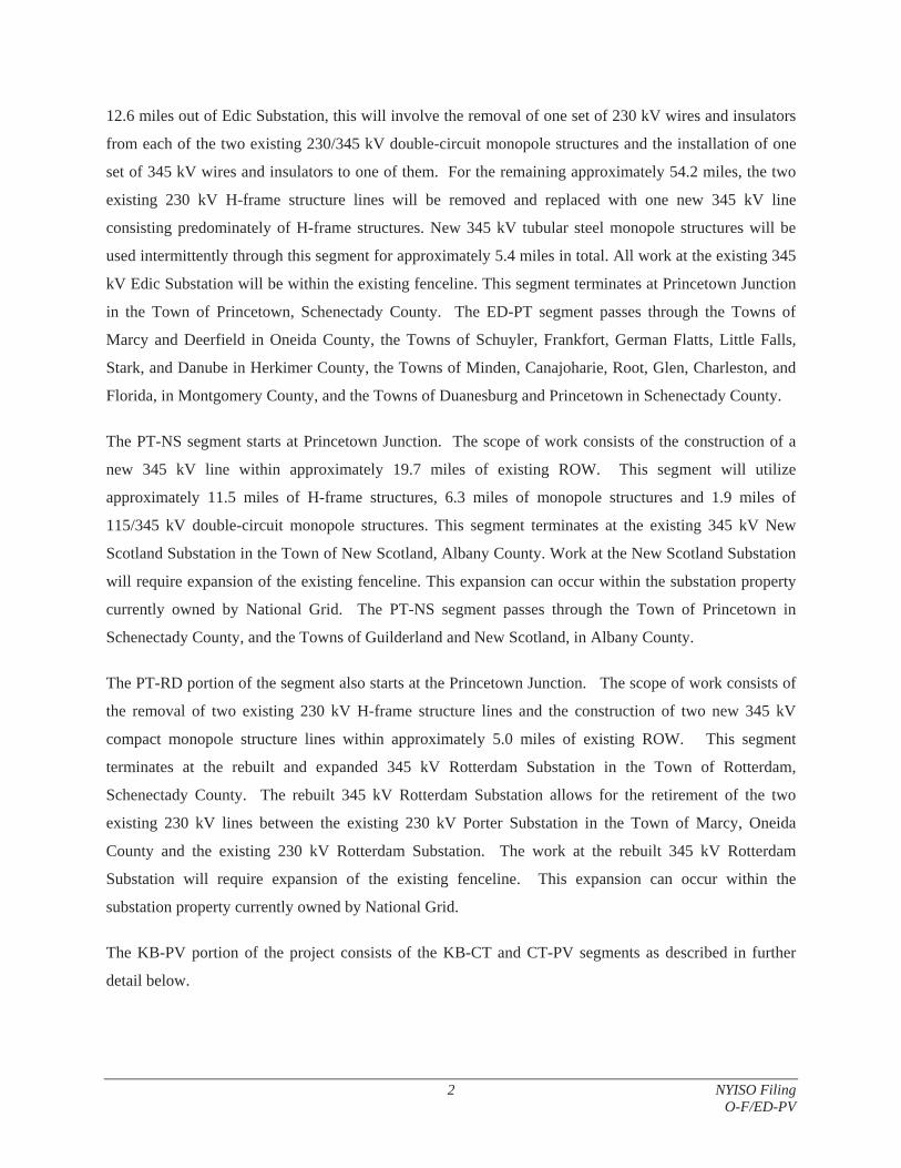
The Oakdale to Fraser and Edic to New Scotland and Knickerbocker to Pleasant Valley 345 kV
Transmission Line Project (O-F/ED-PV) is comprised of six ROW segments: Oakdale to Fraser (O-F),
Edic to Princetown Junction (ED-PT), Princetown Junction to New Scotland (PT-NS), Princetown
Junction to Rotterdam (PT-RD), Knickerbocker to Churchtown (KB-CT), and Churchtown to Pleasant
Valley (CT-PV). The Project includes the rebuild and expansion of the existing 230 kV Rotterdam
Substation to include a 345 kV yard, modifications to the existing 345 kV Edic and New Scotland
Substations, the construction of the new Knickerbocker 345 kV Switching Station, rebuild and expansion
of the existing Churchtown 115 kV Switching Station, and modifications to the Consolidated Edison
Pleasant Valley 345 kV Substation.
The location of the O-F/ED-PV Project is depicted in Figure O-F/ED-PV-1.
3.3.2 Physical Description
The Second Oakdale to Fraser 345 kV Transmission Line component of the Project consists of the
construction of a new 345 kV transmission line of approximately 57.7 miles, starting at the Oakdale
Substation in the Town of Union and terminating at the Fraser Substation in the Town of Delhi, built
parallel to the existing 345 kV NYSEG Line #32 (the “Existing Line”). The substation work includes
installation of new breakers, switches and other ancillary equipment which will be within the existing
fenceline. The proposed design for this segment has been revised since the October 1, 2013 submission.
Now, it will be constructed entirely within existing transmission line ROW using steel monopole
structures, rather than lattice steel structures. To allow this, a modification/relocation involving one to
three structures of the Existing Line will be made to provide adequate clearance between the new line and
Existing Line. The Project ROW traverses Broome, Chenango and Delaware counties.
The ED-NS portion of the Project consists of the ED-PT, PT-NS, and PT-RD segments as described in
further detail below.
The ED-PT Junction portion of the segment starts at the existing 345 kV Edic Substation in the Town of
Marcy, Oneida County. The scope of work consists of the removal of two existing 230 kV lines and the
construction of a new 345 kV line within approximately 66.8 miles of existing ROW. For approximately
2 NYISO Filing O-F/ED-PV
12.6 miles out of Edic Substation, this will involve the removal of one set of 230 kV wires and insulators
from each of the two existing 230/345 kV double-circuit monopole structures and the installation of one
set of 345 kV wires and insulators to one of them. For the remaining approximately 54.2 miles, the two
existing 230 kV H-frame structure lines will be removed and replaced with one new 345 kV line
consisting predominately of H-frame structures. New 345 kV tubular steel monopole structures will be
used intermittently through this segment for approximately 5.4 miles in total. All work at the existing 345
kV Edic Substation will be within the existing fenceline. This segment terminates at Princetown Junction
in the Town of Princetown, Schenectady County. The ED-PT segment passes through the Towns of
Marcy and Deerfield in Oneida County, the Towns of Schuyler, Frankfort, German Flatts, Little Falls,
Stark, and Danube in Herkimer County, the Towns of Minden, Canajoharie, Root, Glen, Charleston, and
Florida, in Montgomery County, and the Towns of Duanesburg and Princetown in Schenectady County.
The PT-NS segment starts at Princetown Junction. The scope of work consists of the construction of a
new 345 kV line within approximately 19.7 miles of existing ROW. This segment will utilize
approximately 11.5 miles of H-frame structures, 6.3 miles of monopole structures and 1.9 miles of
115/345 kV double-circuit monopole structures. This segment terminates at the existing 345 kV New
Scotland Substation in the Town of New Scotland, Albany County. Work at the New Scotland Substation
will require expansion of the existing fenceline. This expansion can occur within the substation property
currently owned by National Grid. The PT-NS segment passes through the Town of Princetown in
Schenectady County, and the Towns of Guilderland and New Scotland, in Albany County.
The PT-RD portion of the segment also starts at the Princetown Junction. The scope of work consists of
the removal of two existing 230 kV H-frame structure lines and the construction of two new 345 kV
compact monopole structure lines within approximately 5.0 miles of existing ROW. This segment
terminates at the rebuilt and expanded 345 kV Rotterdam Substation in the Town of Rotterdam,
Schenectady County. The rebuilt 345 kV Rotterdam Substation allows for the retirement of the two
existing 230 kV lines between the existing 230 kV Porter Substation in the Town of Marcy, Oneida
County and the existing 230 kV Rotterdam Substation. The work at the rebuilt 345 kV Rotterdam
Substation will require expansion of the existing fenceline. This expansion can occur within the
substation property currently owned by National Grid.
The KB-PV portion of the project consists of the KB-CT and CT-PV segments as described in further
detail below.
#*
#*
#*
#*
#*
#*
#*
#*
#*
#*
#*
##
##
##
##
""
##
##
##
##
Knickerbocker (New 345 kV)
Rotterdam (Rebuilt 345 kV)
Princetown
Churchtown(Rebuilt 115 kV)
PleasantValley
(Existing 345 kV)
Leeds
Oakdale (Existing 345 kV)
Fraser (Existing 345 kV)
HurleyAvenue
Athens
New Scotland(Existing 345 kV)
Edic(Existing 345 kV)
HerkimerCounty
WashingtonCounty
OneidaCounty
SaratogaCounty
FultonCounty
OnondagaCounty
MadisonCounty Montgomery
County
RensselaerCounty
SchenectadyCounty
OtsegoCounty
SchoharieCounty
AlbanyCounty
CortlandCounty
ChenangoCounty
DelawareCounty
ColumbiaCounty
GreeneCounty
BroomeCounty
UlsterCounty
DutchessCounty
SullivanCounty
I:\N
atio
na
l_G
rid
\Na
tion
al_
Gri
d_
MX
D\A
ltern
ativ
e_
rou
tes\
NY
ISO
\Alt_
rou
tes_
ED
_N
S_
KB
_P
V_
OD
_F
R_
De
c_2
01
4.m
xd
Legend
New 345 kV Transmission Line (UPNY/SENY)
New 345 kV Transmission Line (Central East)
345 kV Transmission Rebuild (Central East)
New 345 kV Transmission Line (Total East)
Other Project Segment
## Project Station
"" Project Junction
#* Other Project Station
County Boundary0 10 20 30 405
Miles
μSources: BMcD Engineering, ESRI
Oakdale to Fraser andEdic to New Scotland and
Knickerbocker to Pleasant Valley
Figure O-F/ED-PV-1
January 2015

Note: This page intentionally left blank
3 NYISO Filing O-F/ED-PV
The KB-CT segment starts at the new 345 kV Knickerbocker Switching Station in the Town of Schodack,
Rensselaer County. The scope of work consists of the removal of the existing 115 kV double-circuit
lattice structure line and the construction of a new 115/345 kV double-circuit monopole structure line
within approximately 21.9 miles of existing ROW. This segment terminates at the rebuilt and expanded
115 kV Churchtown Switching Station in the Town of Claverack, Columbia County. The rebuilt
Churchtown Switching Station will require an expansion of the existing fence line. This expansion can
occur within the substation property currently owned by NYSEG. The KB-CT segment passes through
the Town of Schodack in Rensselaer County, and the Towns of Stuyvesant, Stockport, Ghent, and
Claverack, in Columbia County.
The CT-PV segment starts at the rebuilt and expanded Churchtown Switching Station. The scope of work
consists of the removal of two existing 115 kV double-circuit lattice structure lines, and the construction
of a new 115/345 kV double-circuit monopole structure line within approximately 32.3 miles of existing
ROW. This segment terminates at the existing Consolidated Edison 345 kV Pleasant Valley Substation in
the Town of Pleasant Valley, Dutchess County. All work at the Pleasant Valley Substation will be within
the existing fenceline. The CT-PV segment passes through the Towns of Claverack, Livingston, Gallatin,
and Clermont in Columbia County, and the Towns of Milan, Clinton, and Pleasant Valley in Dutchess
County.
Additional ancillary work on other system facilities may be required depending on the results of the
NYISO system impact studies.
3.3.3 Electrical Description
It is the Applicant’s expectation that the NYISO will prepare the analysis for the interface transfer impact
for the O-F/ED-PV Project. However, the Applicant has undertaken this analysis and believes the N-1-1
transfer capability for UPNY-SENY to be increased in the range of 1,050 - 1,250 MW. In addition, this
solution also increases the N-1 thermal Central-East transfer capability to be in the range of 350 - 450
MW.
Electrical single-line drawings of the 345 kV system, 115 kV system and individual switching stations
and substations providing circuit-specific line and station data are provided in Section 1.0, Modeling
Data.
Details of line upgrades for the O-F portion of the Project include:
4 NYISO Filing O-F/ED-PV
a. Construct the new O-F segment with 1590 ACSR 54/19 “Falcon” conductor and two shield wires:
(1) an optical ground wire and (2) an Alumoweld 7#7 Conductor.
b. The line will be supported by tubular steel monopole structures.
c. The structures will be galvanized and grey in color.
A summary of the substation modifications for the O-F portion of the Project includes:
a. Oakdale 345 kV Substation: Installation of new breakers and disconnect switches.
b. Fraser 345 kV Substation: Installation of new breakers and disconnect switches.
Details of line upgrades for the ED-NS portion of the Project include:
a. Construct the new 345 kV ED-NS transmission line between the Edic Substation and the New
Scotland Substation using 2-bundle 954 kcmil ACSS “Cardinal” conductor primarily on new 345
kV structures. The majority of proposed structures from ED-PT will be between 0 feet (no
difference) and 20 feet taller than what exists today. For approximately 3.6 miles of this 66.8
mile segment, the proposed structures will be 65 feet taller than what exists today. The proposed
structures from PT-NS will be between 45 feet and 100 feet shorter than what exists today. The
proposed structures from PT-RD will be between 30 feet shorter and 15 feet taller than what
exists today.
b. Remove the two existing 230 kV lines between the Porter Substation and the Rotterdam
Substation.
c. Interconnect the existing 345 kV Edic to New Scotland line into the rebuilt 345 kV Rotterdam
Substation.
A summary of the substation modifications for the ED-NS portion of the Project includes:
a. Edic 345 kV Substation: Relocate the existing 345 kV Fraser line to the spare bay position and
install a new circuit breaker. Terminate the new 345 kV New Scotland line to the bay position
vacated by Fraser line. Existing relaying and equipment will need evaluation for fault duty and
electrical rating.
5 NYISO Filing O-F/ED-PV
b. New Scotland 345 kV Substation: At the New Scotland Substation, new circuit breakers and a
new line position will be added between the two existing bus sections. Existing relaying and
equipment will need evaluation for fault duty and electrical rating.
c. Rotterdam 345 kV Substation: Construct a new 345 kV yard on the existing 230 kV Rotterdam
Substation site, connecting the existing 345 kV Edic to New Scotland line, the existing 230 kV
Rotterdam to Eastover Road line, and to a rebuilt 115 kV yard.
Details of line upgrades for the KB-PV portion of the Project include:
a. Construct the new 345 kV KB-PV transmission line between the new Knickerbocker Switching
Station and the existing Pleasant Valley Substation using 2-bundle 954 kcmil ACSS “Cardinal”
conductor on new double-circuit 115/345 kV structures. The proposed structures for KB-PV will
be between 5 feet shorter to 10 feet taller than what exists today.
b. Remove the existing 115 kV double-circuit lattice structure line in the ROW between the new
Knickerbocker Switching Station and Churchtown Switching Station and the two existing 115 kV
double-circuit lattice structure lines in the ROW between the Churchtown Switching Station and
the existing Pleasant Valley Substation.
c. Rebuild a single 115 kV line between the new Knickerbocker Switching Station and the existing
Pleasant Valley Substation using single 954 kcmil ACSS ”Cardinal” conductor on the new
double-circuit 115/345 kV structures.
A summary of the substation modifications for the KB-PV portion of the Project includes:
a. Knickerbocker 345 kV Switching Station: Construct new 345 kV Knickerbocker Switching
Station connecting to the existing 345 kV New Scotland-Alps line and the new 345 kV
Knickerbocker-Pleasant Valley line.
b. Pleasant Valley 345 kV Substation: Relocate the existing 345 kV Long Mountain line to the
spare bay position and install a new circuit breaker. Terminate the new 345 kV Knickerbocker
line to the bay position vacated by the Long Mountain line. Existing relaying and equipment will
need evaluation for fault duty and electrical rating.
c. Churchtown Switching Station: Demolish and construct a new expanded 115 kV switching
station at Churchtown on the existing Churchtown 115 kV Substation site.

6 NYISO Filing O-F/ED-PV
3.3.4 Innovations Incorporated
[Submitted under separate cover to the ALJs for confidential treatment because it contains confidential information.]
7 NYISO Filing O-F/ED-PV
3.3.5 Other Technologies and Methods Being Studied
8 NYISO Filing O-F/ED-PV
[Submitted under separate cover to the ALJs for confidential treatment because it contains confidential information.]
9 NYISO Filing O-F/ED-PV
10 NYISO Filing O-F/ED-PV
3.3.6 Evidence of Commercially Viable Technology
The transmission facilities proposed for the O-F/ED-PV Project consist of materials that have been
successfully used on transmission lines for decades, including transmission lines in New York.
Overhead Transmission Engineering
Structures will consist of tubular steel, natural wood, or laminated wood. Conductors used on the project
will be aluminum and either steel reinforced (ACSR) or steel supported (ACSS). Although ACSS is less
commonly used, both ACSR and ACSS have been used throughout the industry for 40 years. Hardware
on the project will consist of traditional ceramic insulators and various metallic connectors. The latest
composite core conductors, ACCR and ACCC, which have been in commercial operation for over 10
years, were also evaluated. It was determined that the proposed project can realize the same benefits with
ACSS and ACSR for a fraction of the cost of using ACCR or ACCC. It is estimated that the use of
ACCR conductor would increase total project costs by approximately 30 percent.
Substation Engineering
Structures will consist of tubular steel. The primary conductor used within the substations will be tubular
rigid aluminum. Jumpers and strain conductors will consist of single and bundled steel reinforced
aluminum conductor ACSR or all aluminum conductor AAC. Circuit breakers will be of the SF6 type,
and shall be isolated with open air gang operated disconnect switches. Hardware within the stations will
consist of traditional ceramic insulators and various metallic connectors. The structures, conductor
equipment, and hardware used within the substations have been used throughout the industry for over 60
years. The application for these stations will utilize the latest manufacturing and operational technology
based on this proven technology. All substations will be enclosed within an 8-foot high chain link
security fence.
All material proposed for use on the project can be procured through traditional industry channels.
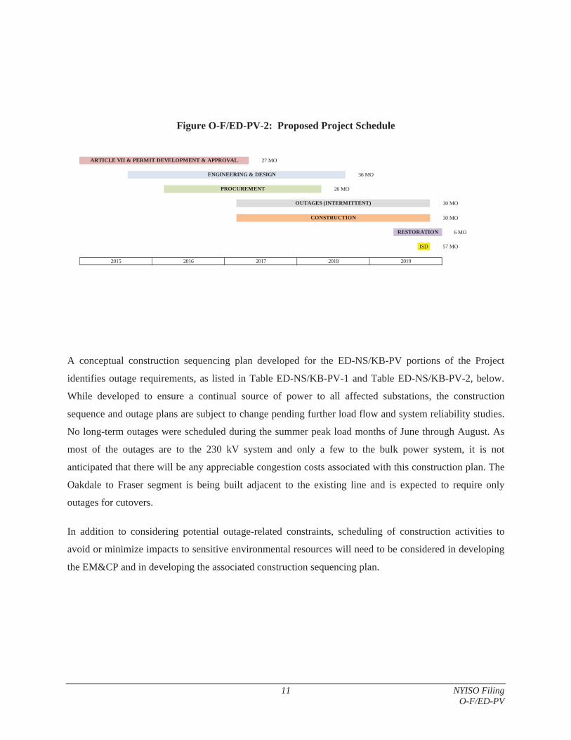
3.3.7 Schedule
The O-F/ED-PV Project is expected to take approximately 57 months to complete. Construction of
substations and overhead lines is expected to take approximately 30 months. A high level schedule for
the O-F/ED-PV Project is provided in Figure O-F/ED-PV-2. Assumptions built into the project schedule
include: commencement of Part B filing in September 2015; staggered EM&CP filing and approvals;
procurement of long lead items begin prior to final EM&CP approval; and intermittent outage schedules
that include consideration for summer reliability constraints.
11 NYISO Filing O-F/ED-PV
Figure O-F/ED-PV-2: Proposed Project Schedule
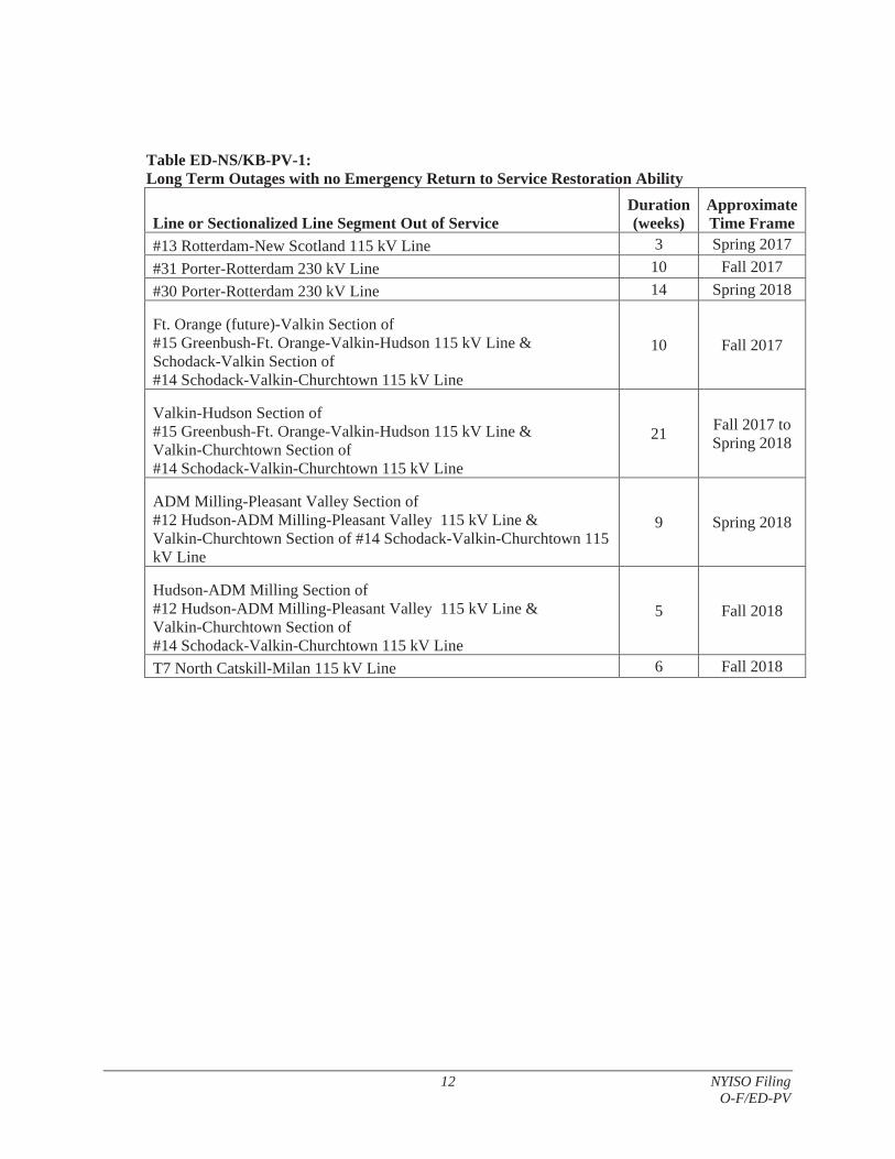
A conceptual construction sequencing plan developed for the ED-NS/KB-PV portions of the Project
identifies outage requirements, as listed in Table ED-NS/KB-PV-1 and Table ED-NS/KB-PV-2, below.
While developed to ensure a continual source of power to all affected substations, the construction
sequence and outage plans are subject to change pending further load flow and system reliability studies.
No long-term outages were scheduled during the summer peak load months of June through August. As
most of the outages are to the 230 kV system and only a few to the bulk power system, it is not
anticipated that there will be any appreciable congestion costs associated with this construction plan. The
Oakdale to Fraser segment is being built adjacent to the existing line and is expected to require only
outages for cutovers.
In addition to considering potential outage-related constraints, scheduling of construction activities to
avoid or minimize impacts to sensitive environmental resources will need to be considered in developing
the EM&CP and in developing the associated construction sequencing plan.
27 MO
36 MO
26 MO
30 MO
30 MO
6 MO
ISD 57 MO
2015 2016 2017 2018 2019
CONSTRUCTION
OUTAGES (INTERMITTENT)
ENGINEERING & DESIGN
PROCUREMENT
RESTORATION
ARTICLE VII & PERMIT DEVELOPMENT & APPROVAL
12 NYISO Filing O-F/ED-PV
Table ED-NS/KB-PV-1: Long Term Outages with no Emergency Return to Service Restoration Ability
Line or Sectionalized Line Segment Out of Service Duration(weeks)
ApproximateTime Frame
#13 Rotterdam-New Scotland 115 kV Line 3 Spring 2017 #31 Porter-Rotterdam 230 kV Line 10 Fall 2017 #30 Porter-Rotterdam 230 kV Line 14 Spring 2018
Ft. Orange (future)-Valkin Section of #15 Greenbush-Ft. Orange-Valkin-Hudson 115 kV Line & Schodack-Valkin Section of #14 Schodack-Valkin-Churchtown 115 kV Line
10 Fall 2017
Valkin-Hudson Section of #15 Greenbush-Ft. Orange-Valkin-Hudson 115 kV Line & Valkin-Churchtown Section of #14 Schodack-Valkin-Churchtown 115 kV Line
21 Fall 2017 to Spring 2018
ADM Milling-Pleasant Valley Section of #12 Hudson-ADM Milling-Pleasant Valley 115 kV Line & Valkin-Churchtown Section of #14 Schodack-Valkin-Churchtown 115 kV Line
9 Spring 2018
Hudson-ADM Milling Section of #12 Hudson-ADM Milling-Pleasant Valley 115 kV Line & Valkin-Churchtown Section of #14 Schodack-Valkin-Churchtown 115 kV Line
5 Fall 2018
T7 North Catskill-Milan 115 kV Line 6 Fall 2018

13 NYISO Filing O-F/ED-PV
Table ED-NS/KB-PV-2: Short Term Outages with no Emergency Return to Service Restoration Ability2
Line Out of Service Duration
(days)#8 Lafarge-Buckley Corners-Blue Stores-Pleasant Valley 115 kV Line 1 #10 Milan-Pleasant Valley 115 kV Line 1 #12 Hudson-ADM Milling-Pleasant Valley 115 kV Line & 1 #13 Churchtown-Pleasant Valley 115 kV Line 1 #14 Schodack-Valkin-Churchtown 115 kV Line 1 #15 Greenbush-Ft. Orange-Valkin-Hudson 115 kV Line 1 T7 North Catskill-Milan 115 kV Line 1 #984 Churchtown-Craryville 115 kV Line 1 #398 Pleasant Valley-Long Mt. 345 kV Line 1-2 #2 New Scotland-Alps 345 kV Line 1-2 #14 Marcy-New Scotland 345 kV Line 2-3 (NYPA) Edic - Fraser 345 kV Line 1-2 (NYPA) #1 New Scotland-Gilboa 345 kV Line 3-4 #94 New Scotland-Leeds 345 kV Line 3-4
3.3.8 Capital Cost Estimates
See Attachment 3 for the capital cost estimate.
3.3.9 Risk Assessment
Permitting Risks
a. The proposed schedule includes 27 months to develop, file and obtain permits from state and
federal agencies. A number of these approvals may lead to additional analysis or approvals.
Schedule delays such as delay in commencing the Article VII Part B process and the ACOE
permit can impact the project in-service date which will increase project costs. Complete permit
filings along with efficient permit processes will minimize any potential schedule delays.
b. It is assumed that the Article VII development and Certificate approval process will not exceed
12 months.
2 Lines identified may be subjected to multiple short term outages as will be required for sectionalizing, station cut-overs and wire installation crossings.

14 NYISO Filing O-F/ED-PV
c. Since a number of environmental field investigations must take place in order to produce state
and federal permit applications, schedule delays that push the window for field investigations
outside of the proper season could delay the permitting development process an additional year.
d. Although the Applicant is striving to address known environmental issues, unanticipated permit
requirements imposed by regulatory agencies can extend construction schedules, impact the in-
service date, and increase project costs. For example, there may be a limitation on when the trees
can be cleared for protection measures associated with the Northern Long Eared Bat.
e. The Cricket Valley Project is in the queue for utilizing the spare bay position at the Consolidated
Edison Pleasant Valley 345 kV Substation. If the Cricket Valley Project should get approved
before this project, a bay addition would be required, which could increase the permitting
schedule and will increase project costs.
Procurement Risk
a. The proposed schedule provides for up to 26 months for the procurement of construction services
and major equipment with long lead times (e.g. circuit breakers, disconnect switches). Risks can
include raw material and manufacturing availability, quality and delivery logistics. Currently, the
Applicant does not see fabrication and delivery problems with the major equipment needed for
this Project. However, if markets change, delays could impact the in-service date
Construction Risk
a. During detailed design, subsurface core borings are performed in intervals along the Project
route. During construction, unforeseen field conditions (e.g. excessive ground water, shallow
bedrock, nested boulders, etc.) can be encountered. Typically, unforeseen field conditions result
in an increased cost to the project. In more extreme cases, schedule impacts also occur.
b. Execution of a large construction project can include project management risks including
securing a large number of labor resources, coordinating project activities, managing schedule,
and keeping the project within budget.
c. The proposed schedule provides approximately 30 months for needed intermittent outage
windows. If construction sequencing, outage sequencing plans, and commissioning sequencing
are delayed due to system conditions and new outages take longer to schedule, the in-service date
(as well as the overall Project cost) can be affected.
15 NYISO Filing O-F/ED-PV
3.3.10 Status of NYISO Interconnection Studies
For the O-F portion of the Project, the NYISO issued the draft SIRS report to NYSEG on November 20,
2014. NYSEG reviewed the draft report and has not further comments at this time. It is anticipated that
the NYISO will be issuing the final SIRS report soon.
For the ED-NS/KB-PV portion of the Project, Applicant has not yet filed with the NYISO an
interconnection request for this portion of the Project and plans to file the request shortly after the filing
of this submission.
3.3.11 Status of Equipment Availability and Procurement
No equipment has yet been procured for the Project.
Long lead items for the switching stations and substations for this Project include circuit breakers,
disconnect switches, support and bus structures, dead end structures, lightning arresters, lightning masts,
capacitor coupled voltage transformers, and control enclosures. Typical lead times for these items range
from 8 to 30 weeks. This equipment is currently not expected to cause schedule delays and are common
station procurement items.
Long lead items for overhead construction include 345 kV structures (lead times of approximately 20 to
26 weeks) and overhead conductor (lead times of approximately 12 to 16 weeks). This equipment is not
currently expected to cause schedule delays.
3.3.12 Status of Contracts
There are currently no contracts under negotiation or in place relative to this Project.
3.3.13 Demonstration of Site Control
The Project will be constructed entirely within existing Applicant ROW on property either owned in fee
by the Applicant or on property which the Applicant has easements for transmission construction. The
Applicant has site control of all station locations with the exception of the 345 kV Pleasant Valley
Substation which is owned by Consolidated Edison.
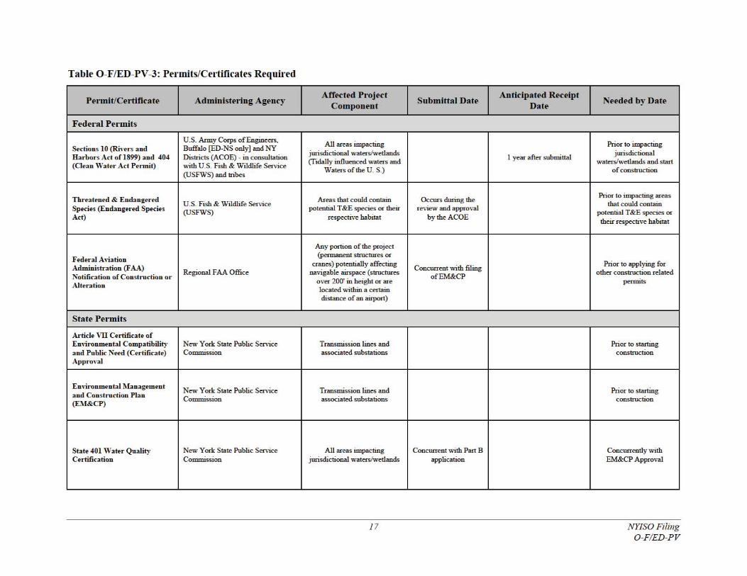
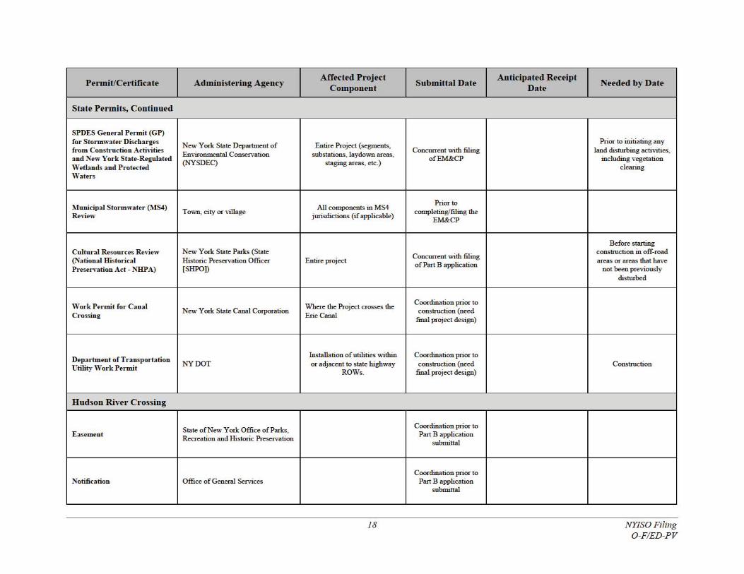
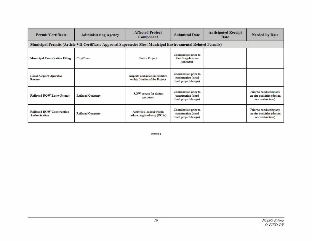
3.3.14 Status of Permits
No permits or certificates for the O-F/ED-PV Project have been received to date. Long lead permits
include concurrent submittal and review for an Article VII Certificate and ACOE 404 Permit, and DPS

16 NYISO Filing O-F/ED-PV
EM&CP approval (post Article VII approval, staggered submissions over 19 months). A full list of
permits is provided in Table O-F/ED-PV-3.