Second International Symposium on Marine Propulsors · PDF fileSecond International Symposium...
6
Second International Symposium on Marine Propulsors smp’11, Hamburg, Germany, June 2011 Boundary Layer Control of Twin Skeg Hull Form with Reaction Podded Propulsion Noriyuki Sasaki National Maritime Research Institute (NMRI), Mitaka, Tokyo, Japan ABSTRACT The ZEUS (Zero Emission Ultimate Ship) project of the NMRI (National Maritime Research Institute) is very challenging and is unique from the view point of utilized technologies. This paper will introduce some innovative ideas, which are “reaction pod” and “jet-assist motor propulsion”. Reaction pod is a concept which can increase propulsive efficiency by using off-centered podded propulsors of twin skeg hull form. By putting the pods at the optimum position in the stern, a propeller can act as a contra-rotating propeller. Jet assist motor propulsion can be used for several objectives, such as prevention of flow separation, reducing stern vibration, improving course keeping ability, etc. This paper will explain these two new ideas by introducing model test data which were obtained from NMRI towing tank. Keywords Reaction Pod, Boundary Layer Control, Zero Emission 1 INTRODUCTION The author believes that we still have a lot of innovative hull form design technologies to reduce fuel consumption, in contradiction to the tremendous pessimism throughout the world. It is true that we don‟t have enough room to improve ship performance based on a simple solution, such as reduction of resistance or improvement of propeller efficiency. However, we should know that the energy balance among ship propulsion mechanism is not fully understood even now. Flow field of a ship stern is the most difficult area to understand and we may chance upon a new phenomenon. The technologies which will be introduced here are those of such discoveries. 2 ZEUS PROJECT The total amount of CO 2 emission from ships is estimated to be around 3% of emission from the entire globe, and this figure corresponds to emission amount from the country of Germany. UNFCCC (United Nations Framework Convention on Climate Change) has requested IMO to increase the reduction of GHG (Green House Gas) emitted from ocean going vessels. In order to contribute to this push, NMRI started the ZEUS project in the beginning of 2009 and the following mile stones were decided: ZEUS 1: Reduction of 50% by Hull Form Design, Reaction Pod and Boundary Layer Control ZEUS 2: Reduction of 80% by Hybrid Engine, Solar Energy and Electric Supply System addition to ZEUS1 ZEUS 3: Reduction of 100% by Fuel Cell addition to ZEUS 2 As shown in Figure 1, hydrodynamic technology will play the main role until 2020. After ZEUS 1, it will be required to introduce Hybrid Engine technology. As the final goal, we expect Fuel Cell to be a viable energy supply system for ocean going vessels. The Zero Emission Ultimate Ship (ZEUS) concept has several key technologies, as shown in Table 1. * taking electric conversion loss into account Table 1 : Key Technologies of ZEUS 1 Key technologies Objective Target values Twin skeg hull with wide beam Increase dead weight /power 10% Reaction pod Increase propulsive efficiency 20%(10%*) Spray Tearing Plates (STEP) Reduce added wave resistance 20% of added wave resistance Boundary layer control(JAMP) Reduce viscous resistance Increase propulsive efficiency and maneuverability 20% 2030 2020 2050 ZEUS1 ZEUS2 Hull Form Design Reaction Pod Boundary Layer Control Hybrid Engine Solar Energy Electric Supply System Hull Form Design Reaction Pod Boundary Layer Control ZEUS3 Hull Form Design Reaction Pod Boundary Layer Control Hybrid Engine +Fuel Cell Solar Energy Electric Supply System 50% 100% 80% 2040 year GHG Reduction Rate Figure 1: Mile Stones of ZEUS Project of NMRI
Transcript of Second International Symposium on Marine Propulsors · PDF fileSecond International Symposium...

Second International Symposium on Marine Propulsors smp’11, Hamburg, Germany, June 2011
Boundary Layer Control of Twin Skeg Hull Form
with Reaction Podded Propulsion
Noriyuki Sasaki
National Maritime Research Institute (NMRI), Mitaka, Tokyo, Japan
ABSTRACT
The ZEUS (Zero Emission Ultimate Ship) project of the
NMRI (National Maritime Research Institute) is very
challenging and is unique from the view point of utilized
technologies. This paper will introduce some innovative
ideas, which are “reaction pod” and “jet-assist motor
propulsion”. Reaction pod is a concept which can increase
propulsive efficiency by using off-centered podded
propulsors of twin skeg hull form. By putting the pods at
the optimum position in the stern, a propeller can act as a
contra-rotating propeller. Jet assist motor propulsion can
be used for several objectives, such as prevention of flow
separation, reducing stern vibration, improving course
keeping ability, etc. This paper will explain these two new
ideas by introducing model test data which were obtained
from NMRI towing tank.
Keywords
Reaction Pod, Boundary Layer Control, Zero Emission
1 INTRODUCTION
The author believes that we still have a lot of innovative
hull form design technologies to reduce fuel consumption,
in contradiction to the tremendous pessimism throughout
the world. It is true that we don‟t have enough room to
improve ship performance based on a simple solution,
such as reduction of resistance or improvement of
propeller efficiency. However, we should know that the
energy balance among ship propulsion mechanism is not
fully understood even now. Flow field of a ship stern is
the most difficult area to understand and we may chance
upon a new phenomenon. The technologies which will be
introduced here are those of such discoveries.
2 ZEUS PROJECT
The total amount of CO2 emission from ships is estimated
to be around 3% of emission from the entire globe, and
this figure corresponds to emission amount from the
country of Germany. UNFCCC (United Nations
Framework Convention on Climate Change) has requested
IMO to increase the reduction of GHG (Green House
Gas) emitted from ocean going vessels. In order to
contribute to this push, NMRI started the ZEUS project in
the beginning of 2009 and the following mile stones were
decided:
ZEUS 1: Reduction of 50% by Hull Form Design,
Reaction Pod and Boundary Layer Control
ZEUS 2: Reduction of 80% by Hybrid Engine, Solar
Energy and Electric Supply System addition
to ZEUS1
ZEUS 3: Reduction of 100% by Fuel Cell addition to
ZEUS 2
As shown in Figure 1, hydrodynamic technology will play
the main role until 2020. After ZEUS 1, it will be
required to introduce Hybrid Engine technology. As the
final goal, we expect Fuel Cell to be a viable energy
supply system for ocean going vessels.
The Zero Emission Ultimate Ship (ZEUS) concept has
several key technologies, as shown in Table 1.
* taking electric conversion loss into account
Table 1 : Key Technologies of ZEUS 1
Key technologies Objective Target values
Twin skeg hull with
wide beam
Increase dead
weight /power
10%
Reaction pod Increase propulsive
efficiency 20%(10%*)
Spray Tearing Plates
(STEP)
Reduce added wave
resistance
20% of added
wave resistance
Boundary layer
control(JAMP)
Reduce viscous
resistance
Increase propulsive
efficiency and
maneuverability
20%
20302020 2050
ZEUS1
ZEUS2
Hull Form DesignReaction PodBoundary Layer ControlHybrid EngineSolar EnergyElectric Supply System
Hull Form DesignReaction PodBoundary Layer Control
ZEUS3
Hull Form DesignReaction PodBoundary Layer ControlHybrid Engine +Fuel CellSolar Energy
Electric Supply System 50%
100%80%
2040
year
GH
G R
eduction R
ate
Figure 1: Mile Stones of ZEUS Project of NMRI
2.1 Twin Skeg Hull with Wide Beam
There are three ways to improve EEDI represented by
Equation(1). The first way is to increase capacity as
shown in Figure 2 and this can be achieved by twin skeg
hull form under the limitations of ship length and draft.
The second way is to reduce CO2 by increasing propulsive
efficiency by applying reaction pod and boundary layer
control. The last way is to increase ship speed without any
additional power. There are two countermeasures for this.
One is to increase efficiency of cargo handling/loading
and the other one is to have better sea keeping ability.
Twin skeg hull form itself is not a new idea and a few
vessels of this type have been built. The main difference
between ZEUS and existing twin skeg vessels is an
application of podded propulsion system. By adopting
podded propulsion system, design capabilities of the
vessel can be much improved. The most important point is
that ZEUS requires no shafts and requires an engine room
inside of skegs. This means that the designer can
optimize stern part only taking the optimum propulsive
efficiency into account.
Generally speaking, the beam of a vessel is the most
flexible parameter compared to other main dimensions,
such as ship length, ship draft, etc. because those
parameters are strongly restricted from port limitations.
The beam of a vessel normally has upper limit from the
aspect of maneuverability and this weak point can be
solved easily by applying twin skeg hull form. By
increasing beam until the transportation efficiency reaches
the maximum, the capacity (DWT: Deadweight) can be
increased without sizing up of her length and draft. The
maneuverability is not a big concern because the twin
skeg hull form has a superior course keeping ability from
the very start.
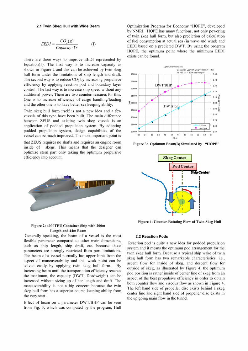
Effect of beam on a parameter DWT/BHP can be seen
from Fig. 3, which was computed by the program, Hull
Optimization Program for Economy “HOPE”, developed
by NMRI. HOPE has many functions, not only powering
of twin skeg hull form, but also prediction of calculation
of fuel consumption at actual sea (in wave and wind) and
EEDI based on a predicted DWT. By using the program
HOPE, the optimum point where the minimum EEDI
exists can be found.
2.2 Reaction Pods
Reaction pod is quite a new idea for podded propulsion
system and it means the optimum pod arrangement for the
twin skeg hull form. Because a typical ship wake of twin
skeg hull form has two remarkable characteristics, i.e.,
ascent flow for inside of skeg, and descent flow for
outside of skeg, as illustrated by Figure 4, the optimum
pod position is rather inside of center line of skeg from an
aspect of the best propulsive efficiency in order to obtain
both counter flow and viscous flow as shown in Figure 4.
The left hand side of propeller disc exists behind a skeg
center line and right hand side of propeller disc exists in
the up going main flow in the tunnel.
)1()(2
VsCapacity
gCOEEDI
Figure 2: 4000TEU Container Ship with 200m
Length and 44m Beam
Figure 4: Counter-Rotating Flow of Twin Skeg Hull
2.50
2.60
2.70
2.80
2.90
3.00
3.10
3.20
3.30
3.40
3.50
30000
35000
40000
45000
50000
55000
60000
65000
70000
32 34 36 38 40 42 44 46 48 50 52 54
DW
T(t
on)/
BHP(k
w)
DW
T
B(m)
Optimum Dimensions
DW(ton)
DWT/BHP
Container; Lpp=196.2m D=19.0m d=11.0m
Vs =20 kts ( 20% sea marigin)
DWT(ton)
DWT/BHP
Figure 3: Optimum Beam(B) Simulated by “HOPE”

Figure 6 shows the result of propulsion test of the
container ship model of Figure 5 and it can be seen that
the propulsive factors varies with the pod position. By
shifting the propeller center to aside, strong wake peak
generated by the skeg, which may provoke harmful
cavitation on ship vibration, can be avoided and it allows
smaller number of blades such as three (3) blades.
Moreover, the clearance between propeller tip and hull
bottom plate can also be reduced. These advantages have
a strong potential to obtain much higher propulsive
efficiency by increasing the propeller diameter.
Figure 7 shows the results of cavitation test obtained from
the same vessel of Figure 5. It is very obvious that the
cavitation extent and propeller induced ship vibration can
be minimized by adopting a reaction pod concept.
2.3 Propulsive Efficiency of Reaction Pod
Owing to extremely high hull efficiency and three-bladed
large diameter propellers, the propulsive efficiency of
reaction pod system is over 90%, while a conventional
propulsion system is around 75%. The improvement is
(90-75)/75=20% and this value can be used directly to the
full scale power reduction.
3 BOUNDARY LAYER CONTROL
As explained in the previous section, the reaction pod
concept brings several advantages, not only propulsive
efficiency but also cavitation performance, and these
advantages show synergetic effects on propulsive
efficiency. Same as the reaction pod concept, BLC
(boundary layer control) has several functions. It can be
said this concept has more functions than reaction pod
concept. BLC mentioned here is the system as shown in
Figure 8 and named JAMP (Jet Assisted Motor
Propulsion).
The system has an inlet near the tunnel starting point and
Figure 5: Reaction Pods Concept and Ship Model with
Pod Traverser
0.4
0.5
0.6
0.7
0.8
0.9
1.0
1.1
1.2
1.3
-0.10 -0.05 0.00 0.05 0.10 0.15 0.20 0.25 0.30 0.35
Y/D
Self propulsion factors
Z/D=0.05D
H
R
t1
w1
Figure 6: Self propulsive factors of Reaction Pod
Propulsion
Figure 7: Cavitation Patterns and Measured Pressure
Fluctuations Obtained From Cavitation Test(22kts)
0.000
0.005
0.010
0.015
0.020
0.025
0.030
0.035
0.040
0.045
0.050
-0.5 -0.4 -0.3 -0.2 -0.1 0.0 0.1 0.2 0.3 0.4 0.5 0.6
KP3
y/Dp
22
3
3Dpn
PKP
Figure 8: JAMP (Jet Assisted Motor Propulsion)
System
assist motor
JAMP( Jet Assist Motor Propulsion)
inlet
outlet
22kts

BLC(Boundary Layer Control)
prevent
the separation
Increase a tunnel slope angle
Maneuvering abilityincrease
the ascent flow
Reduce the resistance
M/E arrangement
Higher Propulsive Efficiency
Cavitation Performance
(reduce propeller induced vibration)
①
②
③
④
⑤
Skeg Center
Ship Center
Pod Center
Figure 9: Multi Functions of JAMP System Utilizing Boundary Layer Control (BLC)
two outlets near the skeg top under the water surface. The
inlet and the outlets are connected by simple tubes and
small impellers are located very close to the outlets.
Figure 9 shows how the BLC concept works.
As shown in the figure, there are totally five (5) functions.
3.1 Main Engine Arrangement (Function 1)
The idea of twin skeg hull is very old and has been studied
from the aspect of ship performance viewpoints. As a
result of the studies, it was concluded that the following
two disadvantages are the most difficult things to apply,
except when a ship has been specially designed as result
of particular requirements, such as an extremely shallow
shaft:
Disadvantage I: Cost of propulsion system
Disadvantage II: Difficulty of engine arrangement
Owing to the higher oil banker price, Disadvantage I is
not as important as before; however, Disadvantage II is
very serious for the ship owner because they may lose big
capacity due to inconvenient engine room arrangement.
In order to move the engine room afterward, a tunnel
slope angle must be increased. However, this means that
the designer loses the energy savings obtained from twin
skeg hull form and this means losing both capital and
interest.
BLC concept can solve this problem without any
disadvantage, as will be explained later.
3.2 Maneuvering Ability (Function 2)
Increment of tunnel slope angle can trigger poor course
keeping ability of twin skeg hull by shortening the skeg
length, which contributes control surface of maneuvering.
By applying BLC, stability forces can be increased and
the course keeping ability of the vessel will reintegrate
into the normal position.
3.3 Cavitation Performance (Function 3)
It is very obvious that the jet flow by BLC can change
retarded flow into smooth flow and clear the cavitation
away from propeller blade surface near the top position
which may induce harmful vibration on the vessel.
3.4 Reduction of Resistance (Function 4)
The most important function of BLC is to prevent the flow
separation on the tunnel wall where the two-dimensional
flow separation easily occurs. By putting two outlets on
the top positions of two skegs, three-dimensional and
strong ascent flow can be generated. The image of this
flow pattern is illustrated in Figure 10. In the figure,
effectiveness of the inlet and outlets can be seen.
3.5 Improve Propulsive Efficiency (Function 5)
By eliminating the separation zone of tunnel flow as
shown in Figure 10, ascent flow of tunnel between two
skegs can be increased and result in high propulsive
efficiency by strengthened contra-rotating flow.
Figure 10: Flow Pattern Image of BLC Effect

4 MODEL TEST
In order to verify the aforementioned functions of JAMP
system utilizing BLC (Boundary Layer Control) for
reaction pod concept, model test listed in Table 2 was
conducted at NMRI towing tanks and NMRI cavitation
tunnel. Regarding the cavitation test, only the result of an
original hull will be shown because the data is not ready in
time. The test with JAMP system will be conducted soon
and the result will be submitted.
4.1 Ship Model, Propeller Models
Model tests were conducted with 5.418 m paraffin model
and twin podded propulsion system at a towing tank of the
National Maritime Research Institute. Table 3 shows
principal dimensions of ship model and propeller models.
4.2 Modification of Tunnel Slope Angle
The most effective utilization of JAMP system is to
modify a tunnel slope angle, as shown in Figure 11.
Based on the program “HOPE”, the form factors (k) of
two configurations are estimated 0.30 and 0.52,
respectively.
4.3 Propeller Loading Test
Boundary layer suction concept is not a new idea for a
wing applied to an aero plane, wing cascade of pump or
turbine, etc. However, the application to a ship is quite
new and only an investigation into the effect of
performance of water jet propulsion can be found. Not
only is the difference between the water jet propulsion
system and JAMP studied, but power ratio (Pimp/Pmain)
is studied as well. Here Pimp and Pmain are absorbed
power of impellers and absorbed power of main propeller.
Because the objective of JAMP is to control the boundary
layer near the stern, power ratio is far from that of water
jet propulsion as below:
)2(10.001.0)/( MAINIMP PP
Model test was conducted varying both main propeller
loading and impeller loading, as illustrated by Figure 12.
The typical example of propeller loading test is shown in
Table 4.
The effectiveness of JAMP system is very clear from Figure 13
and Table 4, where we can see resistance and propulsive
performance at the same time. In Table 4, T is total thrust as
described:
FD TMAIN TIMP FD+T remark
2.55 0 0 2.55 w/o BLC
1.80 0 0.11 1.91 with BLC
0 3.30 0 3.36 w/o BLC
0 2.32 0.09 2.41 with BLC
Table 2: Ship Model and Propeller Model
Kind of model test Conditions
Propeller Loading Test with BLC & w/o BLC
Flow Measurement with BLC & w/o BLC
Oblique Going Test with BLC & w/o BLC
Cavitation Test Original hull
Table 3: Ship Model and Propeller Models
Ship Propellers & Impellers
Lpp(m) 5.418 Dia.(m) 0.226 0.04
B(m) 1.182 Pitch Ratio 1.020 0.70
D(m) 0.2955 Exp.Area Ratio 0.35 0.40
CB 0.6564 Boss Ratio 0.18 0.18
LCB(%) 3.55 No. of Blades 3 4
M/EM/E
Figure 11: Modification of a Tunnel Slope Angle for
Efficient Engine Arrangement of Twin Skeg Hull
Table 4: Obtained Data from Propeller Loading Test
(Vm=1.0m/s, unit=kg)
)3(IMPMAIN TTT
Figure 12: Measuring System of Propeller Loading Test
assist motor
JAMP( Jet Assist Motor Propulsion)
inlet
outlet
FD
TMAIN(N),QMAIN(N),n(rps) TIMP(N),QIMP(N),n(rps)
Vm(m/s)
Main Propeller

The amplification factor ATf of JAMP system base on
thrust can be represented as follows:
Where, with and w/o means with BLC and w/o BLC.
From Table 4, ATf of JAMP system is 6(towing)-
10(model point) and it is very feasible to estimate 7-8 for
ship point which can be figured out after full scale power
prediction. It is also possible to define the amplification
factor APf of JAMP based on power.
From the measurement of torque of main propellers and
impellers, amplification factor APf is concluded as 17,
which is incredibly high.
5 CONSIDERATIONS
The reason for extremely high performance of JAMP
system was investigated by conducting flow measurement
of the position behind the ship stern with rotating
propellers. Two conditions of with BLC and without BLC
were compared in the Figure 15. The flow field of these
two conditions is quite different and clearly explains the
reason of the high performance of BLC system. The
resistance due to momentum loss of two conditions are
calculated and compared with Figure 13. The obtained
result from calculation is abt. 0.8kg, while the difference
of Fd(kg) in Figure 13 is 0.9kg. Therefore, it can be
concluded that main reason of the high performance of
JAMP system is a contribution of Function 4 (reduction of
resistance due to separation).
6 CONCLUSIONS
The key technologies of the Zero Emission Ultimate Ship
(ZEUS) concept are reviewed from the model test data.
From the studies, it is very clear that the concept of ZEUS
is very promising and effective. Main conclusions which
were obtained here are as follows:
By combination of a twin skeg hull form and twin
pods, high propulsive efficiency of more than 90%
can be obtained.
JAMP (Jet Assisted Motor Propulsion) system
utilizing BLC (Boundary Layer Control) is a very
effective solution to solve the disadvantage of an
engine room arrangement of twin skeg hull.
Amplification Factor 17 (obtained power reduction
/input power) of JAMP was obtained from the tank
test, while verification is still underway.
ACKNOWLEDGMENTS
The author would like to express his thanks to Dr. .N. Hirata,
Mr. K. Kume, Dr. Y. Kawanami and Mr. R. Fukazawa for
planning and conducting the accurate and complicated model
tests explained in this paper.
REFERENCES
Peacock, R. E. (1965). „Boundary-Layer Suction to Eliminate
Corner Separation in Cascades of Aerofoils‟. Report and
Memoranda 3663, October, 1965.
Sasaki, N. (2010). „What is the best propeller for ZEUS?‟
International Propeller Symposium, April 2010, Okayama,
Japan.
-2.500
-2.000
-1.500
-1.000
-0.500
0.000
0.500
1.000
1.500
2.000
2.500
-0.500 0.000 0.500 1.000 1.500 2.000 2.500 3.000 3.500 4.000
FD(kg)
T(kg)
TIMP
TMAIN
w/o BLC
with BLC
TMAIN
TMAIN+TIMP
FD
Figure 13: Result of Propeller Loading Test
-0.500
0.000
0.500
1.000
1.500
2.000
2.500
3.000
3.500
4.000
-0.500 0.000 0.500 1.000 1.500 2.000 2.500 3.000
FD(kg)
PMAIN
w/o BLC
Kg-m/s
PMAIN
PMAIN+PIMP
with BLC
Figure 14: Comparison of Power between
with BCL and without BLC
)4(/)()( / IMPWITHDOWDAT TTFTFf
)5()/()()( // OWMAINWITHIMPMAINOWMAINAP PPPPf
Figure 15: Flow Measurement behind the Ship with
Podded Propellers (left w/o BLC, right with BLC)