
Second Interim Summary Report 1966 to Marcn i467 A … · removal of rigid oxide film structures of...
30
Second Interim Summary Report March 9, 1966 to Marcn 5, i467 A STUDY OF THE ADHESION AND COHESION OF METALS M. J. Hordon Prepared under Contract No. NASw-1168 National Research Corporation Cambridge, Massachusetts for NATIONAL AERONAUTICS AND SPACE ADMINISTRATION 12-07 (TWRU) I I L (ACCESSION NUMBER) gN61 B >I (CODE) E i (CA~E+RY) iv https://ntrs.nasa.gov/search.jsp?R=19670021878 2018-07-30T05:43:05+00:00Z
Transcript of Second Interim Summary Report 1966 to Marcn i467 A … · removal of rigid oxide film structures of...
Second Interim Summary Report March 9, 1966 to Marcn 5, i467
A STUDY OF THE ADHESION AND COHESION OF METALS
M. J. Hordon
Prepared under Contract No. NASw-1168 National Research Corporation
Cambridge, Massachusetts
for
NATIONAL AERONAUTICS AND SPACE ADMINISTRATION
12-07 (TWRU) I
I L (ACCESSION NUMBER)
gN61 B >I (CODE) E i
(CA~E+RY) i v
https://ntrs.nasa.gov/search.jsp?R=19670021878 2018-07-30T05:43:05+00:00Z

FOREWORD
This second interim summary report presents the results of research work performed under Contract No. NASw-1168, Amendment 1 for the Office of Advanced Research and Tech- nology, National Aeronautics and Space Administration, during the second annual period from 9 March 1966 to 9 March 1967. An interim report summarizing the first year of effort was issued in May 1966 covering the period 9 March 1965 - 9 March 1966.
The program, entitled "A Study of the Adhesion and Cohesion of Metals", has investigated several aspects of metallic adhesion or cold weld bonding near room temperature and was administered by Mr. J. Maltz, Code RRM, NASA-OART. The research effort may be considered as a continuation of the work on metallic adhesion performed under NASA Contract NO. NASW-734.
The chief investigator for the program was Dr. M. J. Hordon. During the initial phases of the work, he was assisted by J. R. Roehrig and R. P. Giammanco.
Some of the results obtainedsin these studies have been presented at ASTM-ASLE Symposium on Adhesion (Cold Welding) of Materials in Space Environments, Toronto, Yay, 1967.
i

TABLE OF CONTENTS
PAGE
SUMMARY INTRODUCTION APPARATUS
General Design Loading Mechanism Wire Brush Abrasion Device
ADHESION SPECIMENS EXPERIMENTAL PROCEDURE EXPERIMENTAL RESULTS
Effect Effect Effect Effect
DISCUSSION FUTURE WORK
of Compressive Deformation of Lattice Structure of Yield Stress of Lattice Orientation
1
2
4
4
4
7 7
1 3
1 4
1 5
1 8
1 8
20
22
2 5
ii

FIGURE
LIST OF FIGEXES
PAGE
1 2
6
7
8
9
ADHESION TESTING APPARATUS 5 SCHEMATIC OUTLINE OF VACUUM ADHESION TESTING UNIT 6 SPECIMEN SELECTOR ROTATOR DEVICE 8
VIBRATORY ABRASION DEVICE 9
FOR SINGLE CRYSTAL TESTS 10 ADHESION SPECIMENS FOR POLYCRYSTALLINE AND
VARIATION OF THE RELATIVE SELF-ADHESION STRENGTH OF POLYCRYSTALLINE METALS WITH DEGREE OF PLASTIC COMPRESSION 16 EFFECT OF LATTICE STRUCTURE TRANSFORMATIONS ON THE ADHESION EFFICIENCY WITH PLASTIC DEFORMATION 19 VARIATION OF THE BOND EFFICIENCY WITH YIELD
EFFECT OF CRYSTALLINE ORIENTATION ON THE ADHESION EFFICIENCY OF COPPER WITH PLASTIC DEFORMATION 23
STRENGTH 21
iii

A STUDY O F THE A D H E S I O N AND COHESION O F P4ETALS
By M. J. Hordon
National Research Corporation
SUMMARY
Measurements of the interfacial bonding produced by the contact of metal surfaces in vacuum showed that detectable adhesion forces could be obtained at room temperature provided adsorbed surface oxide films were removed and the metals were plastically compressed. Under conditions in which bulk surfaces were mechanically abraded at vacuum levels below 2 x lo'* torr to disrupt and remove adsorbed surface films, and compressive loads ranging up to four times the yield stress were applied to cause extensive plastic flow, self-adhesion strengths varying up to 30 percent of the yield strength of polycrystalline copper were obtained.
adhesion/yield stress ratio, was found to vary markedly with lattice structural type, decreasing in the direction FCC-BCC-HCP of lower coordination number, and with yield strength, decreasing proportionately as the yield increased. The influence of these parameters on the adhesion of clean surfaces was related to the plastic strain response or ductility necessary for macroscopic bonding.
tion in single crystal tests with copper, rising to a maximum with the -110> axial direction, a crystallographic orientation with a relatively lower resolved shear flow stress than comparative c l l l ; or ~100, axial orientations.
The comparative adhesion efficiency, denoted by the
The adhesion strength a l s o varied with lattice orienta-
i

INTRODUCTION
The tendency for many metallic surfaces to adhere across the interface when brought into intimate contact has been well established under the general terms "adhesion", "cohesion" or "cold welding". The phenomenon has generally been attributed to atomic bonding mechanisms, the adhesion energy being provided by the surface energies of the original discrete surfaces.
Investigations of met llic adhesion bonding in vacuum environments below 1 x lo-' torr and at temperatures ranging from 20° to 25OoC have been carried out at National Research Corporation for several years under NASA and U.S. Air Force sponsorship. The general objective has been to obtain experi- mental data on the relative tendency of engineering metals to adhere to each other under contact and to examine the effects of physical and mechanical variables on the adhesion strength. Information of this nature is of obvious interest in the design of devices such as solenoids, valves, bearings, mating flanges, sockets and pins for space vehicle application. In addition, the adhesion response of metals is important in considering cold welding processes in which strong bonding is sought while minimizing excessive temperature and deformation levels.
During the first year of effort in this investigation and from prior research programs at NRC, experimental results of tests of metallic adhesion at room temperature have shown that:
1. Adhesion bonding requires the removal and continued absence of adsorbed oxide and organic surface films. Two techniques to clean contact surfaces in vacuum have been employed in previous work; wire brush abrasion and ion beam bombardment.
2. The adhesion strength was observed to increase with the force of contact, particularly for loads high enough to cause plastic yielding at the interface.
3 . The equivalent adhesion strength of smooth polished surfaces was greater than irregular roughened surface contours due to the larger area of contact.
relatively large adhesion forces were detected for many metals at 2OoC. In this temperature range, diffusion bonding across
With effectively cleaned surfaces and compressive yielding,
2

the interface is generally negligible; interfacial bonding is chiefiy deperideiit ofi i f i t f inate atzmfc centact . Hence the removal of rigid oxide film structures of low bond coordination number and of surface asperities by plastic flow is necessary to achieve atomic bonding over substantial areas.
With increase in temperature or longer contact times at temperatures, the adhesion strength was found to increase due to interfacial diffusion as well as stress relaxation.
to apply to unlike metal surface pairs as well as for the case of self-adhesion. In particular, bonding was observed between unlike metal pairs possessing negligible mutual solid solubility in each other. In this case, the observed rise in adhesion with temperature was less than for the cases of self-adhesion or the adhesion of soluble metal pairs.
The present investigation is chiefly concerned with evaluating the effect of metallic ductility, crystal structure and orientation on the bonding efficiency. The relative ease of plastic flow is closely related to physical and mechanical properties such as lattice structure, yield strength or hardness and crystallographic orientation. Hence the degree of bonding or adhesion efficiency may be expected to vary markedly with these properties. It is understood that variables such as surface cleanliness and degree of plastic deformation need to be normalized in order to correlate changes in adhesion strength with the properties under examination.
favored by lattice structures such as face-centered cubic (FCC) with high bond coordination numbers and by low yield strength, softer metals. However, the effects of surface preparation, contour, compression, interfacial diffusion, etc. have obscured the relationships. In the present work, considerable care was undertaken to eliminate unnecessary variables and to present the experimental data in normalized form in order to validly compare the results of different metals with widely varying properties.
a
The conditions for adhesion outlined above were observed
0 Previous experience has generally shown that adhesion is
3

APPARATUS
General Design
The adhesion testing apparatus used in the present work is a modified design incorporating the basic features of the apparatus used for adhesion testing on NASA Contract No. NASw-734. As shown in Fig. 1, it consists of a cylindrical, stainless steel ultrahigh vacuum chamber 14 in. in diameter. The chamber contains several viewing ports, two ports for the introduction of the ion beam guns, one port for the use of a mechanical wire abrasion device, two ports for manipulative mechanisms and a pressure sensing gauge port.
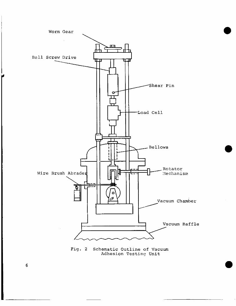
part of the upper flange head. The loading shaft contains a ball and screw drive mechanism which can impose loads up to 2200 lbs on the lower anvil. The linear thrust of the shaft is introduced into the vacuum chamber via a flexible bellows seal. A rigid compression cage fixture is provided to guide the motion of the shaft and insure vertical alignment of the loading stages. Loading may be performed either by a motor driven chain drive or by manual operation of a rotary drive. The resultant force is monitored by a load cell and strip chart recorder.
diffusion pump through a liquid nitrogen cooled baffle trap. The system also contains an NRC 2 inch diffusion pump and a mechanical pump for preliminary evacuation. Concentric "0"- ring seals at the flanges are water cooled to minimize out- gassing. Thermal outgassing of the vacuum chamber up to 25OoC can be maintained by internally mounted quartz rod heaters. The vacuum system when fully loaded with the adhesion testing components is capable of pressures down to 8 x 10⁻¹⁰ torr after outgassing.
The loading assembly, illustrated in Fig. 2 , is an integral
The vacuum chamber is evacuated by a standard NRC 6 inch
Loading Mechanism
An integral part of the loading mechanism are the multi- station specimen loading stages which can sequentially select up to eight adhesion pairs for testing in one pumping operation. These components consist of two rotating stainless steel wheels mounted on the loading shaft and the lower anvil. Specimen samples are mounted in eight recesses provided on the wheel rims.
4

a
a
Fig . 1
Adhesion Testing Apparatus 5
W o r m Gear
Ball Screw Drive 1
W i r e B r u s h Abrade
_.r n
/Shear P i n
-Load C e l l
+- / Rotator
Ye c ha n i sm
Vacuum B a f f l e
F ig . 2 Schematic O u t l i n e of Vacuum Adhesion T e s t i n g U n i t
0
6

When the adhesion apparatus is provided with ion guns mmunted on the vacuum chamber wall, the loading wheels are rotated in clock-wise fashion by weight actuated pulley mechanisms controlled by internal manipulator arms as outlined in the first Annual Summary Report. During the present phase of the investigation, in which the specimen surfaces were cleaned by wire brush abrasion, the ion gun assemblies were removed and rotator mechanisms were positioned in their place. The rotator devices, consisting of an eccentric cam and a series of flexible stainless steel bellows linkages as shown in Fig. 3 , enabled the loading stages to be positioned from outside the vacuum system. The rotator mechanisms can apply torques exceeding 15 in-lb through a distance of 12 in. through the vacuum chamber wall. were employed to lock the stages in one of the indexed test positions after rotation.
0
Manipulator controlled pins
Wire Brush Abrasion Device
The vacuum test assembly contained a wire brush abrasion device to clean test surfaces of specimens immediately prior to contact. As schematically illustrated in Fig. 4 , the flattened stainless steel brush was vibrated through an amplitude of about 3/8 in. at 25 c/sec. by means of a motor and eccentric cam drive mounted outside the vacuum system. The vibration shaft was mounted to a flexible bellows seal so that the brush could be swiveled over the test surfaces and withdrawn.
With this design, the motor drive was removed from the vacuum chamber and gas leakage from sealed motor assemblies as well as limitations to the thermal outgassing temperature were avoided.
a
ADHESION SPECIMENS
Adhesion specimens were prepared of several metals and alloys as listed in Table I. Both polycrystalline and single crystal specimen configurations are illustrated in Fig. 5. Since the upper and lower polycrystalline specimens are crossed at right angles to each other in compression, the
7

Vacuum Seal v
Crank Pin
F l e x i b l e B e l l o w s
Eccen t r i c C a m
Fig. 3 Specimen Selector Rotator Device
8

/- C o n t r o l Spr ing
-- Wire Abrader
F ig . 4
Vibra to ry Abrasion Device
9

POLYCRYSTAL SINGLE CRYSTAL
Fig. 5 Adhesion Specimens for Polycrystalline and for Single Crystal Tests
10

/
Table I
Metal
Copper Nickel Tantalum Titanium Cobalt
304 S.S. 430 S.S. 93 Ag - 7 Sn. 84 Ag -16 Sn. 60 Cu - 40 Zn.
Materials for Adhesion Specimens Polycrystalline
( B brass)
Metal
Copper Copper Copper
Lattice Structure
FCC FCC BCC HCP HCP
FCC BCC FCC HCP FCC
BCC
Single Crystal
Lattice Orientation
(100)
Heat Treatment
8OO0C, 1 hr. 900°C, 1 hr. 12OO0C, 1 hr. 7OO0C, 2 hrs.
12OO0C, 2 hrs.
1O5O0C, 1 hr. 85OoC, 1 hr. 55OoC, 1 hr. 6OO0C, 1 hr. 5OO0C, 1 hr. (slow cool) 5OO0C, 1 hr. (Quenched)
Heat Treatment
8OO0C, 1 hr. 8OO0C, 1 hr. 8OO0C, 1 hr.
11

maximum available bearing area would be 0.141 sq. in. However, the actual nominal bearing area was varied for each adhesion test by chamfering away a fraction of the original surface as shown in Fig. 5. This was done to increase the applied compressive stresses to values above the metal yield stresses.
The polycrystalline metals chosen for evaluation consisked of copper and nickel with the FCC structure, tantalum with the BCC structure and titanium and cobalt with the hexagonal close- packed (HCP) phase structure. In addition, three alloy pairs were selected in which a phase change cousd be induced by either a change in composition or in heat treatment. Thus austenitic FCC 304 Grade stainless steel differs from ferritic BCC Grade stainless principally in the nickel content of the 304 Grade alloy. Similarly, a selected increase in the tin content of the binary silver-tin from 7 to 16 percent will yield a phase change from the FCC alpha phase to the HCP zeta phase.
In the case of the B-brass, 60 Cu-40 Zn alloy, the structure can be varied without changing the composition since the alloy undergoes an allotropic phase change upon heating above 458OC. Under severe quenching conditions, the metastable f3'(BCC) phase will be retained at room temperature in place of the equilibrium a(FCC) phase.
With the exception of the silver-tin alloys, the poly- crystalline specimens were prepared from wrought or extruded bar stock and were heat treated to the annealed condition. The Ag-Sn alloys were prepared in the laboratory by vacuum melting and casting at 105OOC. In this procedure, the required charges of pure silver and tin were heated in a platinum wire resistance furnace in a vacuum of 3 x 10⁻⁵ torr. After agitation of the melt to remove surface dross, the melts were cast into graphite molds. Castings 1 in. in diameter and up to 4 in. long were obtained which were subsequently machined and annealed.
that the alpha alloy had a tin content of 7 . 2 2 percent, well within the phase limit of about 10 percent Sn. The zeta phase alloy had a tin concentration of 16.40 percent, within the phase solubility limits of 12.8 and 19.5 percent Sn at room temperature.
Subsequent chemical analysis of the Ag-Sn castings showed
12
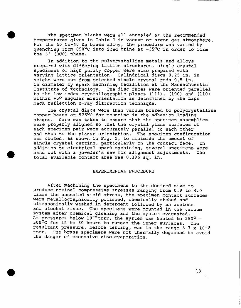
The specimen blanks were all annealed at the recommended temperatures given in Table I in vacuum or argon gas atmosphere. For the 65 Cu-40 Zn brass a l l o y , the procedure was varied by quenching from 85OoC into iced brine at -35OC in order to form the 8 ' (BCC) phase.
In addition to the polycrystalline metals and alloys prepared with differing lattice structures, single crystal specimens of high purity copper were also prepared with varying lattice orientation. Cylindrical discs 0.25 in. in height were cut from oriented single crystal rods 0.5 in. in diameter by spark machining facilities at the Massachusetts Institute of Technology. The disc faces were oriented parallel to the low index crystallographic planes (1111, (100) and (110) within +50 angular misorientation as determined by the Lape back reFlection x-ray diffraction technique.
copper bases at 575OC for mounting in the adhesion loading stages. Care was taken to ensure that the specimen assemblies were properly aligned so that the crystal plane surfaces of each specimen pair were accurately parallel to each other and thus to the planar orientation. The specimen configuration was chosen, as shown in Fig. 5, to minimize the amount of single crystal cutting, particularly on the contact face. In addition to electrical spark machining, several specimens were hand cut with a jeweler's saw for alignment adjustments. The total available contact area was 0.196 sq. in.
a
The crystal discs were then vacuum brazed to polycrystalline
EXPERIMENTAL PROCEDURE
After machining the specimens to the desired size to produce nominal compressive stresses ranging from 0.9 to 4.0 times the annealed yield stress, the specimen contact surfaces were metallographically polished, chemically etched and ultrasonically washed in detergent followed by an acetone and alcohol rinse. The specimens were mounted in the vacuum system after chemical cleaning and the system evacuated. At ressures below 10-6torr, the system was heated to 250° - resultant pressure, before testing, was in the range 3-7 x 10⁻⁹ torr. The brass specimens were not thermally degassed to avoid the danger of excessive zinc evaporation.
300 g C for 15 to 30 hours to outgas the inner surfaces. The
13

Prior to the adhesion testing, machined and heat treated cylindrically-shaped specimens approximately 0.75 in. in diameter and 1 in. in height were prepared for experimental measurement of the compressive yield strength, determined as the stress level for deviation of the compressive load- elongation curve from a linear response. The compressive yield strength, denoted as CJ , was taken as a fundamental material parameter with whit# to compare the adhesion strength ur.
In conducting the adhesion tests, specimen pairs of each metal were successively rotated to the vertical loading position and subjected to vibratory brush abrasion for 60-120 seconds to remove surface chemisorbents. Pressure bursts up to 3 x l o e 8 torr were sometimes observed during abrasion, but the usual pressure rise was below 1.5 x lO'*torr. after abrasion, the samples were brought together in contact with less than '5 sec exposure time between cleaning and loading, well below the pressure-time critical exposure limit for substantial reoxidation.
applied stress was in the range 0.9 - 4.0 u , as previously determined. test apparatus was 2200 lb, the maximum compressive stress for the maximum contact area of 0,141 sq. in. was 15,600 psi. However, higher nominal bearing stresses were obtained by reducing the available contact area of the specimen surfaces. Generally, the total contact area was in the range 0.01-0.15 sq. in., permitting compressive stresses as high as 220,000 psi.
The specimen pairs were held in loaded contact for 5 min. at room temperature. The tensiJe rupture or interfacial separation force was then determined. Compressive and tensile force measurements were obtained by a strain gauge load cell positioned on the loading column. The load cell response was graphically recorded with time with a sensitivity of - +1 lb force .
Immediately
The applied contact load was adjusted so that the nominal
Since the maximum load capacity of the adhesion
EXPERIMENTAL RESULTS
Adhesion measurements were carried out on the metals and alloys listed in Table I1 for applied compressive stresses
14
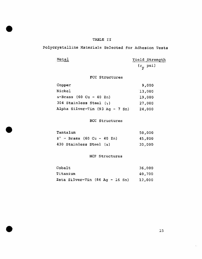
TABLE I1
Polycrystalline Materials Selected f o r Adhesion Tests
Metal Yield Strength
FCC Structures
Copper 9,000
a-Brass (60 Cu - 40 Zn) 19,000 Nickel 13,000
304 Stainless Steel ( y ) 27,000 Alpha Silver-Tin (93 Ag - 7 Sn) 24,000
BCC Structures
Tantalum 8 ' - Brass (60 Cu - 40 Zn) 430 Stainless Steel ( a )
HCP Structures
50,000 45,800 30,000
Cobalt 36,000 Titanium 40,700 Zeta Silver-Tin ( 8 4 Ag - 16 Sn) 12,000
15

varying from about 1-4 times the compressive yield strength. The nominal stress level was adjusted for each specimen pair by varying the area of contact as well as the applied load.
The compressive yield strength u was determined for each material from a standard load-con&action curve using a Riehle tensile test unit. The yield stress was taken as the minimum indicated deviation from linearity with a sensi- tivity of +2 percent applied load. Values of u are presented in Table IT.
For each adhesion test, the tensile adhesion or rupture stress or and the applied compressive stress u were determined for the nominal contact area. A relative measure of the ad- hesion strength was taken as the stress ratio ur/u , denoted as the bonding efficiency. to the yield stress would imply complete bonding, particularly for an extremely ductile or plastic solid. Since most metals extensively strain harden during deformation, however, u may assume values higher than u for perfect wleding. however, the efficiency ratyo ur/uy may be expected to be a fraction less than unity. For ur/u < the residual
Y
N
Thus a tensile rupture stzess equivalent
In mokt cases,
Y . adhesion strength may be considered negligible.
Effect of Compressive Deformation
In order to compare the intrinsic adhesion bonding efficiency of various metals on an equivalent basis, the dependence of the relative bonding strength with the degree of compressive deforma- tion was examined. The results are given in Fig. 6 in which the bonding efficiency factor ur/uy is plotted against the com- pressive plasticity as given by the stress ratio u /u . Values of UN/O greater than unity indicate plastic flow at the interface.
with increased plastic deformation in the compressive stress range U ~ L U . Generally, negligible bonding was observed in the elastic stregs range corresponding to values of the ratio UN/Uy<l. Within the plastic deformation range corresponding to values of uN/u from 1 to 4 , the bonding efficiency varied widely for differext metals, ranging from approximately 10-3 for tantalum, indicating minimal adhesion strength, to values as high as 0.3 for copper, indicating extensive cold welding.
less than unity imply gross elastic loadi!g;Yvalues Y
It is evident that the adhesion strength increased substantially
16

1.0
10-1
H
t I I 1.0 2.0 3.0 4 . 0
DEFORMATION RATIO ( a /u ) N Y
Fig. 6 Variation of the Relative Self-Adhesion Strength of Polycrystalline Metals with
Degree of Plastic Compression
17

It may be noted that the slope d(or/Uy)/d(uu/a ) of the curves in Fig. 6 defines the values of the adhesionYcoefficient or/'3N as a function of the amount of plastic deformation. The ratio or/uN was observed to increase with the value of u N , the rate of increase being substantially greater for ductile metals such as Cu with lower elastic moduli than the less ductile metals such as Ta and Co. The sharp increase in bonding efficiepcy with interfacial deformation indicates the importance of achieviqg extensive surface plastic flow for large scale adhesion of metals at room temperature.
Effect of Lattice Structure
It is apparent from the adhesion efficiency-deformation curves in Fig. 6 that ductile FCC single phase metals typically showed greater relative adhesion than metals with less coordinated structures or less ductility. In order to emphasize the influence of lattice structure on adhesion, bonding efficiency vs. deformation ratio plots are presented in Fig. 7 for the alloys 93 Ag - 7 Sn, 84 Ag - 16 Sn, 304 and 430 Grade stainless steels and 60 Cu - 40 Zn @-brass in which phase transformations were effected by changes in solute content or heat treatment.
The results indicate that the FCC phases invariably showed greater bonding efficiency than either BCC or HCP phases, even though in the case of the silver-tin alloys, the FCC structure with 7 percent tin had a considerably higher yield stress than the HCP zeta phase (16 percent tin).
Extrapolated values of the bonding efficiency taken at aN/u compression, showed reductions of approximately 16 in @-brass and 4 in both the silver-tin and stainless steel systems in transforming to the lower coordination number lattice structure. Similarly to the pure metals, the rate of increase in adhesivity with deformation was generally proportional to the ductility or low strain hardening rate of the alloy.
= 1, corresponding to the onset of plastic yielding under
Effect of Yield Stress
The wide divergence in bonding efficiencies observes. within the same lattice structure grouping, as shown in Fig. 6 and 7, may be attributed to the individual resistance to plastic yielding and flow exhibited by each metal. In order to
18

H W H
I I I I I 1.0 2.0 3.0 4.0
DEFORMATION RATIO ( a /a ) N Y
Fig. 7 Effect of Lattice Structure Transformations
Deformation on the Adhesion Efficiency with Plastic
19
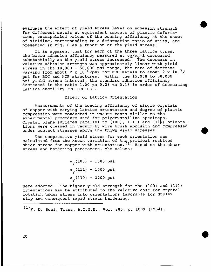
evaluate the effect of yield stress level on adhesion strength for different metals at equivalent amounts of plastic deforma- tion, extrapolated values of the bonding efficiency at the onset of yielding, corresponding to a deformation ratio of unity, are presented in Fig. 8 as a function of the yield stress.
It is apparent that for each of the three lattice types, the basic adhesion efficiency measured at a ~ / u =1 decreased substantially as the yield stress increased. ?he decrease in relative adhesion strength was approximately linear with yield stress in the 10,000 - 50,000 psi range, the rate of decrease varying from about 2 x 10’6/psi for FCC metals to about 2 x psi for BCC and HCP structures. Within the 15,000 to 30,000 psi yield stress interval, the standard adhesion efficiency decreased in the ratio 1.00 to 0.28 to 0.18 in order of decreasing lattice ductility FCC-BCC-HCP.
Effect of Lattice Orientation
Measurements of the bonding efficiency of sing$e crystals of copper with varying lattice orientation and degree of plastic compression were conducted in vacuum tests similar to the experimental procedure used for polycrystalline specimeps. Crystal plane surfaces parallel to (loo), (111) and (114) orienta- tions were cleaned in vacuum by wire brush abrasion and compressed under contact stresses above the known yield stresses.
calculated from the known variation of the critical resolved shear stress for copper with orientation.(l) Based on the shear stress and hardening parameters, the values:
The compressive yield stress for each orientation was
0 (100) - 1600 psi
~ ~ ( 1 1 1 ) - 1500 psi Y
0 (110) - 1200 psi Y
were adopted. The higher yield strength for the (100) and (111) orientations may be attributed to the relative ease for crystal rotation under stress into orientations favorable for duplex slip and consequent rapid strain hardening.
(l)F. D. Rosi, Trans. A.I.M.E., Vol. 200, p. 1009 (1954).
20

i n - 1 5 x I U
10-1
5 x 10-
I I 1 I
‘0 \
\ o \
FCC- 0
BCC- 0 HCP- D
\ 0 \o \
\ \ \ \
4 0
F i g
10
. 8 V a r i
20 30
YIELD STRESS ( a p s i
. a t i o n of t h e Bond E f f i Yie ld S t r e n g t h
Y
21

The effect of crystalline orientation under plastic load on the adhesion bonding efficiency is shown in Fig. 9. AS in the case for polycrystalline materials, the adhesion efficiency increased proportionally to the amount of plastic deformation in the plastic stress range. However, the bonding efficiencies were in the ratio of approximately 2.2 to 1 between crystals with the (110) orientation and crystals with the (100) and (111) contact surfaces.
The higher bonding efficiency of (110) oriented crystals was maintained throughout the plastic deformation range tested and can be correlated with the lower yield stress and lower strain hardening rate observed for this orientation. It may be noted that with substantial plastic strain, the copper crystals exhibited adhesion efficiencies above 0.8, implying nearly complete residual surface welding on a macroscopic scale. For comparison, annealed polycrystalline copper had a maximum adhesion efficiency of about 0.3 in the same plastic stress range.
DISCUSSION
It is evident that significant residual adhesion forces, above 1 percent of the metallic yield stress, can be produced between metal surfaces of macroscopic size at room temperature where diffusion bonding is considered negligible. The degree of adhesion can be related to the effectiveness in generating intimate metal atom contact across the bulk interface. Inter- facial contact, in the absence of appreciable diffusion, will depend primarily on the removal of adsorbed oxide surface layers, i.e. clean surfaces, and on mechanical ductility or plastic flow under compression to relieve localized elastic stresses and to broaden the initial area of atomic contact.
Pre-contact surface abrasion for the disruption and removal of adsorbed oxide films may be understood as a means to promote atomic contact across the interface. It may be expected that abrasion would produce relatively cleaner surfaces for metals such as Cu, Ni, B-brass and the Ag-Sn alloys with less tenacious oxides and lower oxygen adsorption energies than the more reactive metals such as Ta and Ti.
22

1.0
0.8
0.6
0 . 4
0.2
0 0 1.0 2.0 3.0 4.0
DEFORMATION RATIO (a /a ) N Y
Fig. 9 Effect of Crystalline Orientation on the
Plastic Deformation Adhesion Efficiency of Copper with
23

The lower adhesion efficiencies obtained for the latter metals may be partially attributed to the greater difficulty in removing the adsorbed layers.
the residual adhesion strength may be correlated to the ductility requirement for extending interfacial contact. The application of bulk contact stresses in the elastic range be- low the bulk yield stress produced negligible macroscopic welding. Although localized plastic flow at asperities in contact may be expected under nominally elastic loading, the large elastic component of the applied force will act to shear asperity weldments upon release of the load. The result will be to reduce asperity bonding below the experimental detection limit of 1 lb.
With extensive plastic flow, however, corresponding to compressive stresses above the yield stress, u /a >1, the interfacial bonding area can become suf f icienflyYlarge to reduce the elastic shearing forces below the critical shear fracture stress. The effect of lattice structure and yield strength on the adhesion efficiency may then be attributed to their influence on the strain hardening rate and the related amount of plastic flow. Generally, metals with the FCC structure and with relatively low yield. strengths flow easily and produce large areas of interfacial bonding and correspondingly high adhesion efficiencies. The controlling parameter appears to be yield ductility as determined by the rate of strain hardening and the total amount of plastic strain.
work, the orientation dependence of adhesion may also be attributed to the ductility criteria. Since the abrasion treatment to remove surface oxides will produce heavily flowed surfaces layers to a depth of 3 to 5 p , the spatial atomic array at the contact surface asperities are likely to be substantially distorted. The divergence in bonding strength with initial crystal orientation may then be attributed to the variation of ductility and yield stress with orientation in the undistorted bulk crystal underlying the plastically deformed surface layers.
The effect of plastic deformation and yield strength on
In the single crystal studies reported in the present
2 4

In s-miary, it inay be noted that inost engineering materials, with yield strengths above 25,000 psi and with limited ductility due to rapid work hardening, will generally produce extremely small adhesion stresses at room temperature, in the range of about 0.1 percent of the yield strength, for the normally encoun- tered interfacial contact stresses. The present results imply that in the absence of high temperature diffusion, adhesion between clean metallic bulk surfaces would be practically negligible unless extensive plastic deformation occurred. This is most likely with softer, more ductile metals than are generally used for structural purposes.
FUTURE WORK
Having outlined the general effects of severaA of the important mechanical and physical parameters on the extent of metallic adhesion in the present and in previous programs, it has been proposed that future research on adhesion at low temperatures proceed along the following lines.
1. Investigation of the bonded area - The nature of the adhesion force and the mechanism of interfacial adhesion will become clearer if an estimate of the fraction of the total contact surface permanently welded can be made. Estimates of the bonded area may be derived from electrical resistivity measurements supplemented by metallographic sectioning and examination. The object would be to correlate the adhesion force and bonded area determination with compressive stress level.
2. Determination of the extent of plastic flow - As indicated in the present report, a fundamental parameter influen- cing the room temperature adhesion efficiency is the extent of plastic flow at the interface. The strain level may be correlated to the plastic stress index u /u but deformation indexes based on stress do not account for gheywide variation in strain response or work hardening rate. Accordingly, it has been proposed to measure the compressive strain deformation during an adhesion test in vacuum and to compare the adhesion efficiency directly to the total plastic strain level.,
3 . Metallographic study of the adhesion interface - It may be expected that the observed adhesion strength will be strongly dependent on the experimental conditions. It has been
a
25

proposed to study in detail the nature of the welded interface by optical and electron metallography. This effort may be related to the proposal listed above for the measurement of the actual bonded area. Of particular interest is the formation of interfacial zones differing in phase from the bulk solids and the metallographic effect of changes in single crystal lattice orientation. To support the microscopical observations, it has been proposed to carry out micro hardness traverse measurements across the bonded interface.
26


