
SECO V3 SVT comments
57
1
Transcript of SECO V3 SVT comments

1

2

3

This course provides an overview of low pressure carburizing (LPC) technology, laying the foundation for understanding today’s modern equipment and processes, and the evolutionary path that LPC technology has traversed, from the 1960s to today. Discussion of standard equipment, as well as advanced set-ups that accommodate equipment and product flexibility, are provided. Case studies demonstrate both the process and flexibility of LPC to garner excellent outcomes for industrial applications.
4

Upon completion of this course the student will be able to:Define low pressure carburizing (LPC) in both theory and process.Describe the history of development behind today’s LPC technology and the barriers that were overcome in the process.Discuss LPC equipment.Explain advances in LPC technology that allow for flexibility and adaptability of both equipment and outcome.
5

6

Although discovered in the 1970s, vacuum carburizing began to be used in industry worldwide about two decades ago and now serves as an advantageous alternative to atmosphere carburizing for many case hardening applications.
In comparison to traditional atmospheric technology, today’s low pressure carburizing (LPC) presents many advantages, especially in carburizing precision and uniformity, carburizing gas efficiency, energy consumption, and post process product emission.
7

Low pressure carburizing is characterized by: a very high ratio of carbon transfer at the interface, which results in very rapid transport of carbon to the charge surface. This makes the carburizable surface area a key variable.
8
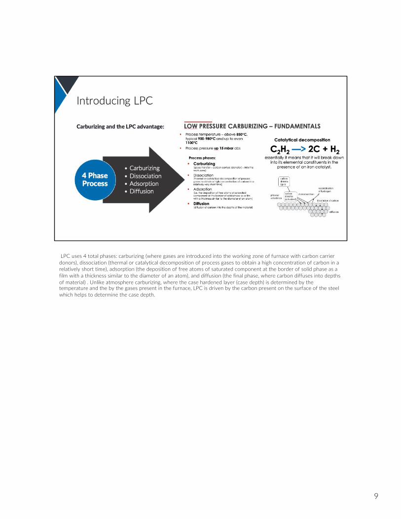
LPC uses 4 total phases: carburizing (where gases are introduced into the working zone of furnace with carbon carrier donors), dissociation (thermal or catalytical decomposition of process gases to obtain a high concentration of carbon in a relatively short time), adsorption (the deposition of free atoms of saturated component at the border of solid phase as a film with a thickness similar to the diameter of an atom), and diffusion (the final phase, where carbon diffuses into depths of material) . Unlike atmosphere carburizing, where the case hardened layer (case depth) is determined by the temperature and the by the gases present in the furnace, LPC is driven by the carbon present on the surface of the steel which helps to determine the case depth.
9

Low pressure carburizing, thanks to its advantages, is now becoming a more popular option. Some industries have used it for many years in select applications. However, advances in process controls have allowed for it to have distinct advantages over atmosphere carburizing.
These qualities are both technical and economic. Advances in gas flow controls and process modeling have made it more competitive with atmosphere carburizing. Also, the potential to carry out LPC at elevated temperatures can shorten process times, resulting in savings.
10

Successful LPC requires careful matching of the quantity of carbon to the surface area to be carburized. This requirement makes careful gas flow control essential. Dosing of the carbon source gas can be determined using the LPC process simulator, which is built into the furnace control system (some manufacturers do this, but not all). Dosing is done by precision valves to ensure repeatability of mass and flow settings.
11

What parts of the carburizing process do we control? There are four key elements: Time, temperature, mass flow rate, and pressure. Time refers to time of the phases or segments of the cycle recipe, temperature control is necessary for uniform results, mass flow rate dictates the quantity of carburizing gas introduced into the furnace, and finally, the pressure required.
12

Advantages in vacuum carburizing:Higher carbon fluxes – vacuum environment makes the transfer carbon to the steel surface fasterAbsence of intergranular oxidation – no igo because of vacuum environmentFaster processing – capability of higher temperatures due to type of equipmentProcess flexibility allows treatment of densely packed loads, blind holes partsNo decarburization of steel can occur due to lack of carbon potential atmosphereProcess and cycle flexibilityCreation of any desired carbon profile, due to simulator capability – greater flexibilityEasy modification of surface carbon contentProcessing methods produce very uniform case and carbon profiles throughout the parts and especially blind holes parts
13
Advantages in quality:High uniformity and repeatability within the parts and loadsSimulation assists in making the exact requested carbon profileProcess flexibility allows to treat densely packed loads, blind holes partsIdeal surface qualityTypically less distortion (LPC + HPGQ)Very little grinding or cleaning needed afterwardsNo intergranular oxidation (IGO)
14

Advantages in environmental impacts:Process is clean, safe, and simple to operate and easy to maintainWorking conditions are excellentMinimal consumption and emission of process gasesLess post heat treatment optionsNo costs of byproduct neutralization – cleaning of tars or carbon monoxide scrubbing resulting from endogas generation
15

Advantages in production process impact:Easy integration and automatization into manufacturing lineNo furnace atmosphere conditioning neededFlexibility in operationConsumption of energy, process gases by the equipment and process only when needed, due to the nature of the vacuum operation
16

Advantages in economics:Fast processing, increases productivityShorter cycles, less energy and gas consumption – lower production costsLess distortion, lower post machining costsNo equipment conditioning – no idling costsHigher profitability
17
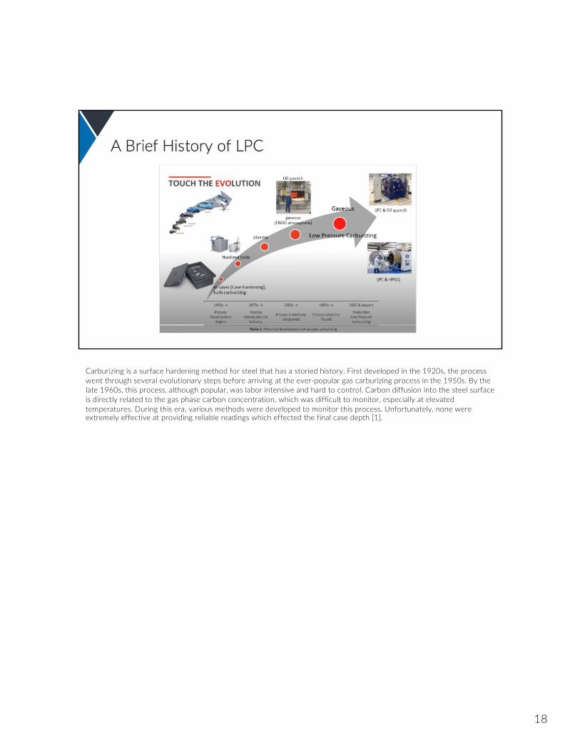
Carburizing is a surface hardening method for steel that has a storied history. First developed in the 1920s, the process went through several evolutionary steps before arriving at the ever-popular gas carburizing process in the 1950s. By the late 1960s, this process, although popular, was labor intensive and hard to control. Carbon diffusion into the steel surface is directly related to the gas phase carbon concentration, which was difficult to monitor, especially at elevated temperatures. During this era, various methods were developed to monitor this process. Unfortunately, none were extremely effective at providing reliable readings which effected the final case depth [1].
18

Without the capabilities of modern microprocessors, the only reliable way to monitor the process was to use shim stock. Extracting these coupons on a regular basis and weighing them throughout the carburizing cycle provided the means to track the development of the case hardened layer. By the late 1960s, this practice was in use by the industry [1].
Although reliable, extracting samples periodically over the course of an eight, twelve, or sixteen hour-cycle had its challenges. The periodic nature of this process required labor resources and constant monitoring. As a result, industry began the search for alternatives for process control. This led to the development of new process monitoring devices such as the oxygen probe. The oxygen probe had the ability to monitor the residual oxygen present in the furnace atmosphere which could then be directly tied to the carbon potential of the furnace atmosphere [1].
19
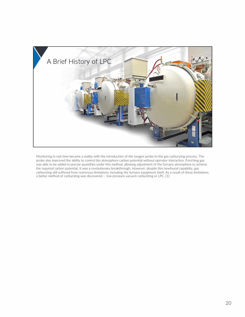
Monitoring in real time became a reality with the introduction of the oxygen probe to the gas carburizing process. The probe also improved the ability to control the atmosphere carbon potential without operator interaction. Enriching gas was able to be added in precise quantities under this method, allowing adjustment of the furnace atmosphere to achieve the required carbon potential. It was a revolutionary breakthrough. However, despite this newfound capability, gas carburizing still suffered from numerous limitations, including the furnace equipment itself. As a result of these limitations, a better method of carburizing was discovered -- low pressure vacuum carburizing or LPC. [1]
20

The search for better controls created the opportunity for LPC technology. LPC differs from atmosphere gas carburizing in that it is carried out at pressures below atmospheric pressure, which requires use of a vacuum furnace instead of the traditional atmosphere furnace equipment. Early attempts at this process in the early 1970s used propane as the carbon source gas. However, using propane as a source gas produced vast amounts of soot and other carbon based contaminations, leaving the furnace in need of maintenance. With propane, LPC was an impractical method. However, by the 1990s, a better general understanding of the reaction chemistry of hydrocarbon gases at low pressures revealed the potential of acetylene as a carbon source for LPC. [1]
21

Ken Kubota of the JH Corporation in Japan patented the first such process in 1996. Acetylene (C2H2) provided what other carbon source gases could not: the potential to achieve the desired case depth with virtually no soot, thanks to steel’s ability to catalyze its decomposition. In the cases where acetylene cannot provide adequate carbon, it is combined with other gases such as ethylene (C2H4) to increase the carbon supply for a given material.
Regardless of whether acetylene only, or a gas mixture is used, a furnace is equipped with highly accurate gas flow control equipment. Processing an alloy capable of hardening by high pressure gas quenching (HPGQ) can also be used for LPC. [1]
22

Since the new development of the 2000s, LPC has offered a distinct and advantageous alternative to atmospheric furnaces.
New equipment designs, control of process, simulator software, and processing methods, as well as the use of acetylene instead of propane or methane as carrying gas, all assure excellent quality, increased productivity, and capacity.
23

The typical LPC process involves the load being placed in a cold chamber which is then heated to the austenitizationtemperature. Typically, this is in the range between 1660 °F and 1750 °F (870 °C and 950 °C). Acetylene is then added at a flow rate adequate to maintain a furnace pressure of about 8 torr (10 mbar). A process recipe that alternates between segments introducing acetylene and segments allowing the carbon to diffuse into the material are most common. This alternating segment pattern is needed because the catalytic cracking of acetylene occurs much faster than does the diffusion of carbon into the steel. Once started, the alternating pattern continues until adequate carbon has been introduced and it has been allowed to diffuse to the required depth. This process is then followed by either a high pressure gas or oil quench, depending on the material being case hardened [1].
24

This differs from typical gas carburizing where the load is placed in a hot chamber at a similar temperature range but at atmospheric pressure. Here, the carbon source gas (typically a combination of endo-gas and enriching gas), flows through the chamber continuously to generate the appropriate carbon potential. When the carbon potential of the atmosphere is correct, the conditions are maintained to allow carbon to diffuse into the surface of the steel until the desired effective case depth is achieved. Then, the load is transferred to quench, which is typically an oil bath. [1]
25

The development of more sophisticated modeling and control methodologies has allowed LPC to take a more prominent role in industries requiring case hardened components, replacing atmosphere gas carburizing. This is especially true in automotive and aerospace power transmission where gears can be made from alloys that are capable of hardening using HPGQ technologies and effective case depth requirements are in the range of 0.040 inches with a required surface hardness of 58 to 62 HRC. Key advantages of the combination of LPC and HPGQ make LPC the preferred choice over traditional gas carburizing and oil quenching in scenarios like those encountered with gears. Those key advantages include:
Decreased distortionElimination of intergranular oxidation (IGO)No decarburizationHigh productivityHigh accuracy and repeatability Shortened cycle times
These advantages extend LPC to many other applications in industries such as tool and die, energy, and transportation [1].
26

Another advantage of LPC is that a wide array of vacuum furnace equipment is available to support it.
To begin, let’s examine the single chamber high-pressure gas quench (HPGQ) furnace. This unit combines LPC and gas quenching at pressures up to 25 bar. This pressure, combined with the ability to quench with gases such as nitrogen in a heating chamber with 360° gas flow ensures that case hardened components reach the required hardness while minimizing distortion.
27

LPC can also be adapted into a multi-chamber furnace to facilitate oil quenching. For instance, an integral quench design features a vacuum heating chamber to support LPC and a separate oil quenching chamber. Here, the load is introduced into the heating chamber through the quenching vestibule with a loader. Once in the heating chamber, the load is heated and LPC is completed. Then, the load is extracted from the heating chamber and moved to the quenching chamber, where it is quenched [1].
28

The use of multi-chamber furnace arrangements provides LPC with the potential to operate in a semi-continuous environment. This expands throughput potential to higher volumes as required, for example, by the automotive transmission component industry. The addition of a preheating chamber means that the load will reach be partially heated (up to 750 °C or 1,380 °F) before entering the main heating chamber where it reaches the austenitizationtemperature and LPC is carried out. The load then moves into either a HPGQ or oil quenching chamber. In this configuration, throughput can reach levels nearly twice that of the comparable two chamber furnace [1].
29

LPC can also be adapted to continuous throughput applications, or, single piece flow. Here, parts are placed in the furnace one piece at a time. This allows a single workpiece to move through the heating chamber where it reaches the austenitization temperature and LPC is carried out. Then, it reaches a quenching chamber where it undergoes the HPGQ process in nitrogen using pressures up to 10 bar while being rotated. This unique process minimizes distortion and provides individual part traceability [1].
30

Although this wide array of furnace equipment provides significant LPC capability, it has its limitations. This is especiallytrue when workpiece size becomes a main consideration. Workpieces that have a large diameter or could suffer from creep-related distortion during the carburizing process are sometimes difficult to accommodate in traditional vacuum furnaces. Instead, these parts are typically processed in a vertical orientation in a pit type furnace.
31

Atmosphere pit carburizing is the traditional method used for large or heavy workpieces.
32

As shown, the load is often supported by a fixture and moved by an overhead crane between the loading station, furnace, and quench tank. This movement includes the transfer between the carburizing furnace and the quench tank when the load is hot. Although common, this method exposes the operator to a dangerous work environment, not only because of the intense heat given off by the load as it transfers, but also the risk of fire if being quenched in oil. This situation coupled with factors such as:Long process timesA flammable atmosphere (endogas and methane)Maintenance of costly furnace components such as retorts and circulating fansFurnace conditioningProcess monitoring (using sample coupons or continuous monitoring devices)Presence of intergranular oxidation Furnace conditioning
These limitations make atmospheric pit less desirable than other equipment choices. LPC provides a safe and cost-effective alternative to this process, but the traditional vacuum furnace equipment is not offered in a pit configuration until now [1].
33

A pit style LPC system is an innovative design that combines a cold wall vacuum furnace with an oil quench tank. This arrangement provides the platform to carburize large and heavy parts using the LPC process instead of traditional atmosphere gas carburizing. To facilitate this process, where the load must be transferred to the quench tank in air while hot, the furnace has the unique ability to open at processing temperature. Rod style metallic heating elements incorporated into a ceramic fiber lining make this possible due to their ability to resist oxidation. In a traditional graphite or molybdenum lined vacuum furnace, the graphite would quickly oxidize at elevated temperatures. This furnace does not include a retort for containment for the process gas atmosphere [1].
34

The system analyzed here includes a furnace and quench tank with a working zone of 70” (1800 mm) diameter 120” (3000 mm) depth. This envelope allows it to accommodate a gross load mass of up to 17,600 lb. (8000 kg). A heating power of 360 kW allows it to reach a maximum temperature of 2,012 °F (1,100 °C). The integrated vacuum pumping system allows it to reach the 10-2 torr (10-2 mbar) vacuum range, which is sufficient for LPC. The furnace is also equipped with an LPC system which uses acetylene as the carbon source gas and includes an LPC process simulator. Forced nitrogen cooling is also included for faster temperature drop before quenching to limit distortion by quenching [1].
35

Case StudyTo illustrate the advantages of using LPC in this furnace system for carburizing large and heavy parts, a case study was completed on a load with the following characteristics [1]
Mass: 13,230 lb. (6000 kg)Steel Grade: SAE 4820 (18CrNiMo7-6)Desired Effective Case Depth (ECD): 0.157” (4.0mm) at 50 HRCCarburized Surface Area: 215 sf (20 sq. m) Carburizing Temperature: 1,700 °F (925 °C)
36

This load was simulated in both a gas carburizing cycle in a traditional atmosphere pit type furnace and LPC in the Pit-LPC system. The comparison is based on both an atmosphere gas carburizing furnace at a plant and LPC data retrieved in the laboratory Pit Style-LPC furnace. The steps used in the gas carburizing cycle are shown in Table 1 [1].
Table 1. Atmosphere carburizing process description.
Gas Carburizing @ 1,700 °F (925 °C) Cycle StepsHeat up to 1,560 °F (850 °C)Soak at 1,560 °F (850 °C)Heat up to 1,700 °F (925 °C)CarburizeCool to 1,500 °F (820 °C)Oil QuenchTemper at 360 °F (180 °C)
37

Meanwhile, LPC was simulated at two different temperatures to understand the effect of carburizing temperature on the cycle time. The corresponding LPC cycle steps are shown in Table 2 for 1,800 °F (980 °C) and Table 3 for 1,900 °F (1040 °C) [1].
Table 2. LPC carburizing process description at 1,800 °F (980 °C)
LPC @ 1,800 °F (980 °C) Cycle StepsHeat up to 1,800 °F (980 °C)CarburizeCool and soak at 1,500 °F (820 °C)Oil QuenchTemper at 360 °F (180 °C)
Table 3 then shows the LPC cycle steps used at 1,900 °F (1040 °C).
Table 3. LPC carburizing process description at 1,900 °F (1040 °C).
LPC @ 1,900 °F (1040 °C) Cycle StepsHeat up to 1,900 °F (1040 °C).CarburizeCool and soak at 1,500 °F (820 °C)Oil QuenchTemper at 360 °F (180 °C)
38

Results and AnalysisAll three carburizing processes combined with an oil quench and temper yield similar metallurgical results. The micrograph in Figure 14 illustrates the resulting structure which is martensite with approximately 10% retained austenite.
The accompanying hardness profile is shown in Figure 15. In this case, the surface hardness reached nearly 62 HRC on the surface and the effective case depth (ECD) was 0.157” (4 mm) as defined by 52.5 HRC or 550 HV) while maintaining an appropriate ASTM grain size of 7. This profile was the result of the 1,800 °F (980 °C) LPC process [1].
39

To reach these results, the cycle durations shown in Figure 16 were required. It is important to note that gas carburizing conducted at 1,700 °F (925 °C) cycle requires nearly 80 hours to complete. Meanwhile, LPC conducted at 1,800 °F (980 °C) required only 42 hours to complete, which is almost a 50% reduction. A further increase in carburizing temperature to 1,900 °F (1040 °C) reduced the time to 26 hours which is a 68% reduction.
The reduced cycle time realized by the Pit Style-LPC decreases the utility use and virtually eliminates carbon dioxide and carbon monoxide emissions. The utility usage displayed in Table 4 shows an energy savings of 53% when LPC is used instead of atmosphere gas carburizing. Increasing the carburizing temperature while using LPC results in an increased savings of 61%. Also, it is important to note that LPC eliminates the need for natural gas and the corresponding CO2 / CO emissions.The corresponding cycle utility costs show that switching to LPC has the potential of a 47% savings. An increase in the LPC temperature yields an even higher savings of 54% [1].
40
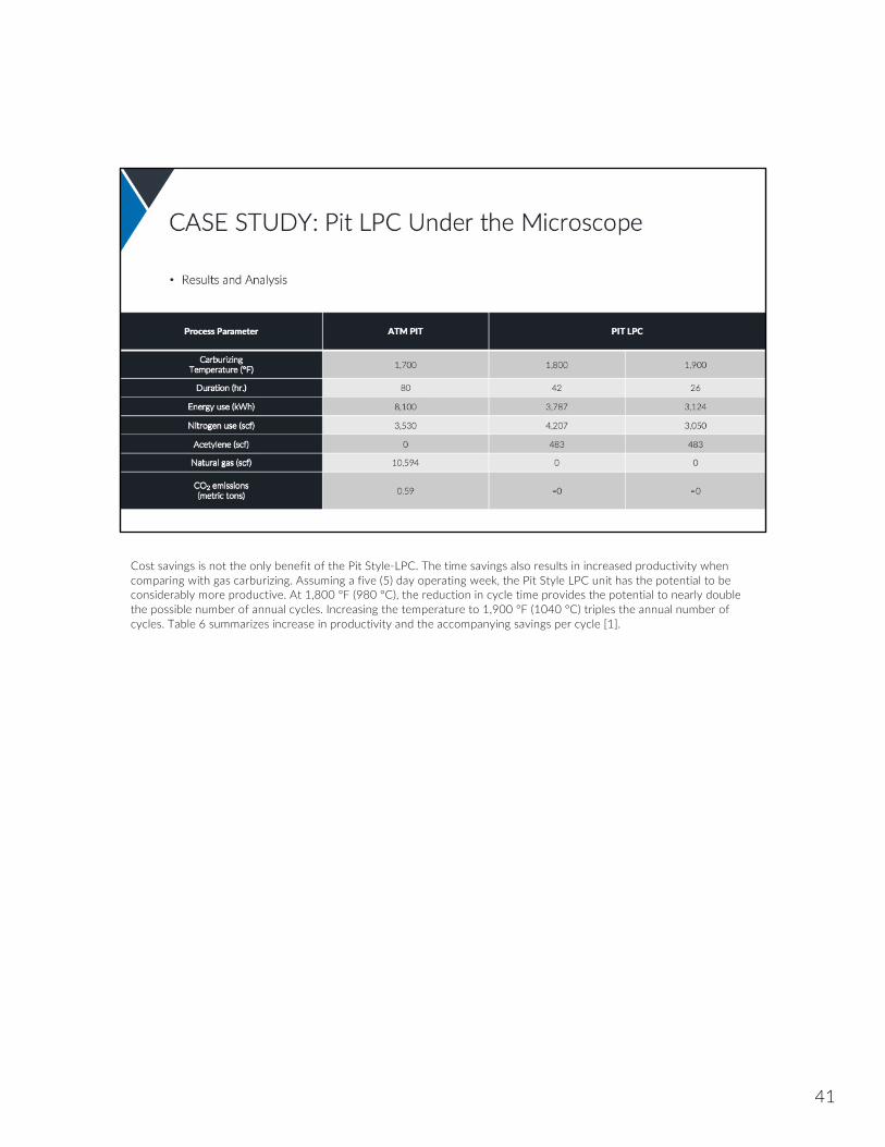
Cost savings is not the only benefit of the Pit Style-LPC. The time savings also results in increased productivity when comparing with gas carburizing. Assuming a five (5) day operating week, the Pit Style LPC unit has the potential to be considerably more productive. At 1,800 °F (980 °C), the reduction in cycle time provides the potential to nearly double the possible number of annual cycles. Increasing the temperature to 1,900 °F (1040 °C) triples the annual number of cycles. Table 6 summarizes increase in productivity and the accompanying savings per cycle [1].
41
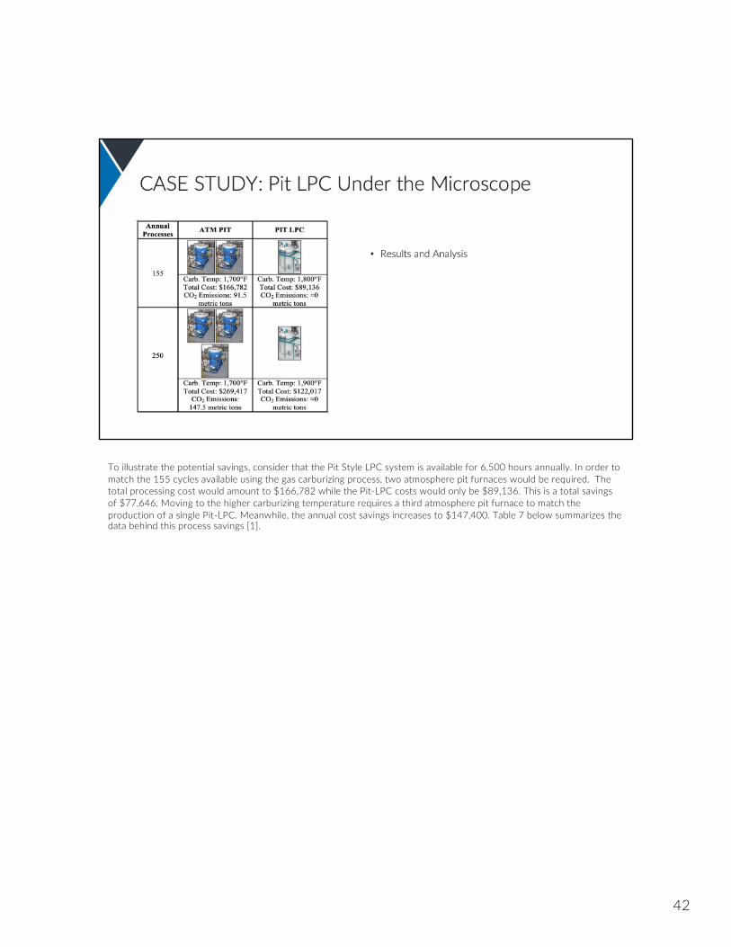
To illustrate the potential savings, consider that the Pit Style LPC system is available for 6,500 hours annually. In order to match the 155 cycles available using the gas carburizing process, two atmosphere pit furnaces would be required. The total processing cost would amount to $166,782 while the Pit-LPC costs would only be $89,136. This is a total savings of $77,646. Moving to the higher carburizing temperature requires a third atmosphere pit furnace to match the production of a single Pit-LPC. Meanwhile, the annual cost savings increases to $147,400. Table 7 below summarizes the data behind this process savings [1].
42

The Pit-Style LPC demonstrates many advantages when compared to atmosphere gas carburizing for case hardening large and heavy parts. The most notable advantage is the potential for reduced cycle time. Shorter cycles result in lower utility costs and increased productivity which reduces the period of return on investment. Along with this financial benefit comes the near elimination of CO / CO2 emissions, increased safety of a vacuum furnace, along with the elimination of the flammable atmosphere and open flames It is also important to note the potential for increased profit that comes with having fewer furnaces (less staff, operational costs, capital costs, etc.) that are more productive. These advantages can allbe delivered by a furnace system that can be placed in the same location as an atmosphere pit furnace and accommodate the part geometries and weights that are expected from pit furnaces [1].
43

Special carburized alloy steel is produced by Carpenter Technology Co. and intended specifically for use in heat-resistant drive units operating at temperatures exceeding the operating temperature of AISI 9310 steel.
Two additional alloys, molybdenum and copper distinguish it from commonly used steels for carburizing. Molybdenum increases the heat resistance and improves resistance to abrasion wear, whereas copper improves the resistance to shock load and lubrication properties.
44
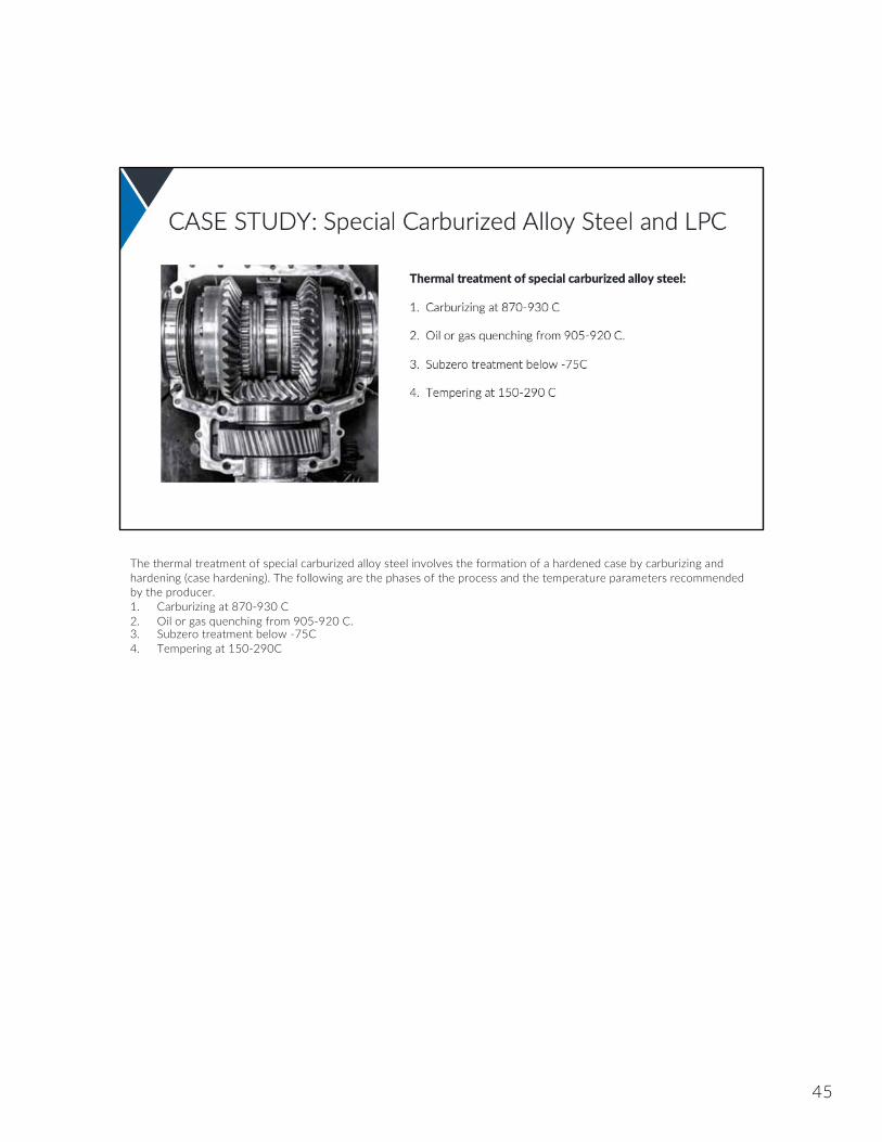
The thermal treatment of special carburized alloy steel involves the formation of a hardened case by carburizing and hardening (case hardening). The following are the phases of the process and the temperature parameters recommended by the producer.1. Carburizing at 870-930 C2. Oil or gas quenching from 905-920 C.3. Subzero treatment below -75C4. Tempering at 150-290C
45

Analysis was done to see if a vacuum furnace with LPC carburizing system, enabled for high-pressure gas quenching, could create the special carburized alloy steel and bring any advantages to the process.
The process ran according to the following sequence:1. Vacuum carburize using flexible low pressure carburizing technology.2. Slow cooldown followed by annealing and continued cooling to the ambient temperature3. Heat up for quenching and high pressure nitrogen quenching4. Subzero treatment in a cryogenic chamber5. Temper in nitrogen
46
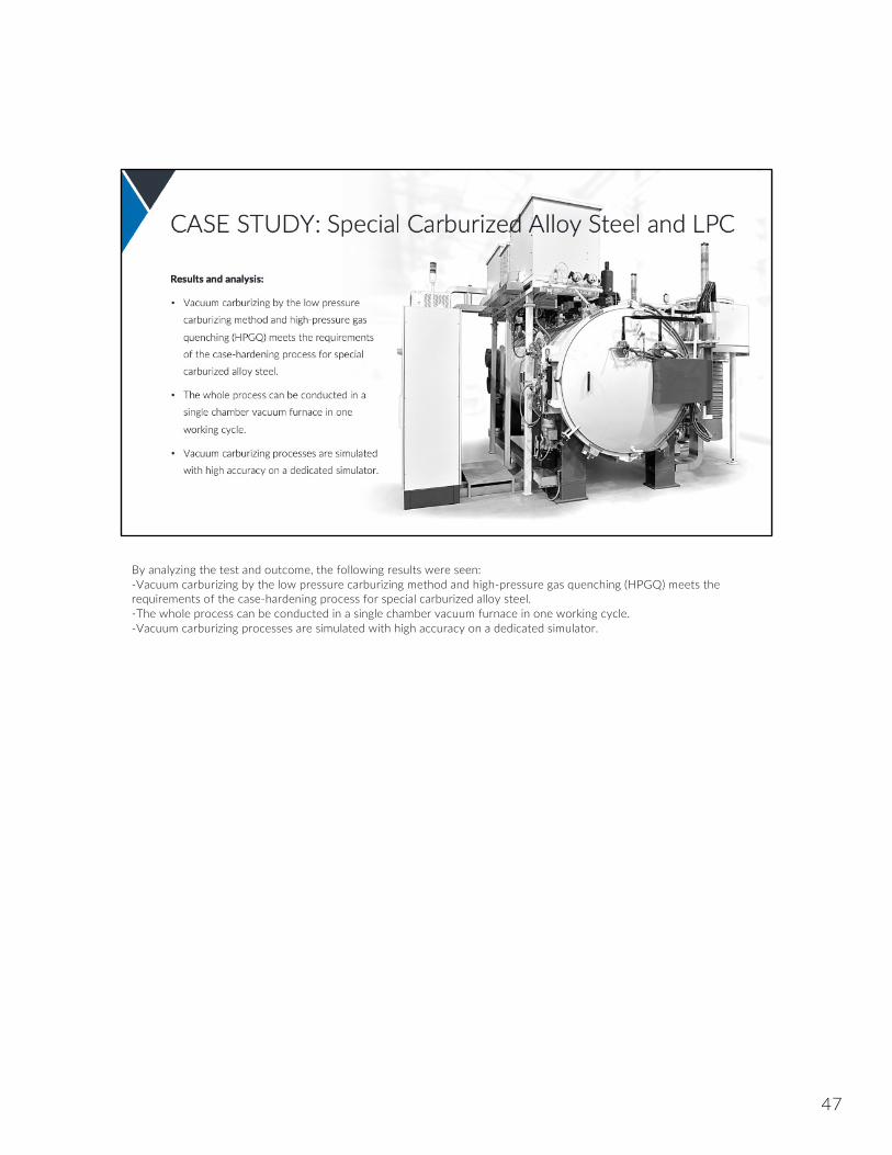
By analyzing the test and outcome, the following results were seen:-Vacuum carburizing by the low pressure carburizing method and high-pressure gas quenching (HPGQ) meets the requirements of the case-hardening process for special carburized alloy steel.-The whole process can be conducted in a single chamber vacuum furnace in one working cycle.-Vacuum carburizing processes are simulated with high accuracy on a dedicated simulator.
47
It is justified to apply an elevated carburizing temperature, which reduces the process duration greatly – for example, four times at a temperature of 980 C.The case hardness profile depends mainly on the carbon concentration profile, but it is also affected by the temperature of quenching, subzero treatment, and tempering.The temperature of quenching directly affects the core hardness (the higher the temperature the higher the hardness), which reaches 37-43 HRC at temperatures of 870-955 C.The temperature process of the subzero treatment affects the degree of the austenite transformation. The optimum temperature is -90 C.
48
49

Why LPC? It offers…The highest quality and uniformity of the process Excellent quality of the surface No surface oxidation (IGO) Reduction of the necessary media to the minimum = savings
50

Quick high-temperature process Minimum consumption of process gases Time savings as there is no need to prepare the process atmosphere Quick process initiation that does not require purging nor atmosphere conditioning as in atmosphere furnaces Safety: No flammable or explosive atmosphere Low heat emission and no pollution (CO & CO2) ECO friendly solution
51

Carburizing costs & time reductionHigh quality (clean and bright) parts following heat treatmentHigh reliabilityVery good process repeatabilityNo load decarburization and oxidationEnvironmentally friendly – no CO2 emission
52

No open fireCleanness of workplaceNo additional measuring equipmentFull automation of the processesVisual computer control system and simulations
53

54

55

56

57