seca 101 Administrator's Manual
40
from software version 1.2.3 seca 101 Administrator's Manual
Transcript of seca 101 Administrator's Manual

from software version 1.2.3
seca 101
Administrator's Manual

2 •
English
CONTENTS1. System description . . . . . . . . . . . . . . . . . . . . . . . . . . . 3
1.1 Intended use . . . . . . . . . . . . . . . . . . . . . . . . . . . . . 31.2 Description of function. . . . . . . . . . . . . . . . . . . . . . 3
Transmission of data by seca scales and stadiometers . . . . . . . . . . . . . . . . . . . . . . . . . . . 3 Printing . . . . . . . . . . . . . . . . . . . . . . . . . . . . . . . 3 Transmitting data to a PDMS. . . . . . . . . . . . . . . 3 Managing patient data. . . . . . . . . . . . . . . . . . . . 3 Access rights. . . . . . . . . . . . . . . . . . . . . . . . . . . 3
1.3 User qualification . . . . . . . . . . . . . . . . . . . . . . . . . . 4 Installation and administration . . . . . . . . . . . . . . 4 Measuring mode . . . . . . . . . . . . . . . . . . . . . . . . 4
2. Safety information . . . . . . . . . . . . . . . . . . . . . . . . . . . . 4
2.1 Safety rules in the instructions for use . . . . . . . . . . 42.2 Basic safety information. . . . . . . . . . . . . . . . . . . . . 4
Using the software. . . . . . . . . . . . . . . . . . . . . . . 4 Using measured results . . . . . . . . . . . . . . . . . . . 5
3. Installation. . . . . . . . . . . . . . . . . . . . . . . . . . . . . . . . . . . 6
3.1 System requirements. . . . . . . . . . . . . . . . . . . . . . . 6 PC hardware and software . . . . . . . . . . . . . . . . 6 seca components . . . . . . . . . . . . . . . . . . . . . . . 6
3.2 Installing the PC software . . . . . . . . . . . . . . . . . . . 73.3 Using the seca print configurator . . . . . . . . . . . . . . 83.4 Obtaining version information . . . . . . . . . . . . . . . . 9
4. Overview . . . . . . . . . . . . . . . . . . . . . . . . . . . . . . . . . . . 10
4.1 Main window . . . . . . . . . . . . . . . . . . . . . . . . . . . . 104.2 Settings window . . . . . . . . . . . . . . . . . . . . . . . . . 114.3 Identification on the packaging . . . . . . . . . . . . . . 12
5. Managing the system. . . . . . . . . . . . . . . . . . . . . . . . . 13
5.1 Starting/exiting the PC software . . . . . . . . . . . . . 13 Opening a software window . . . . . . . . . . . . . . 13 Exiting the PC software . . . . . . . . . . . . . . . . . . 13 Starting the PC software . . . . . . . . . . . . . . . . . 13
5.2 Making default settings . . . . . . . . . . . . . . . . . . . . 14 Assigning a password . . . . . . . . . . . . . . . . . . . 14
Specifying software window behavior . . . . . . . 15 Setting up Autosend . . . . . . . . . . . . . . . . . . . . 16
5.3 Configuring modules . . . . . . . . . . . . . . . . . . . . . . 18 Selecting a module . . . . . . . . . . . . . . . . . . . . . 18 Configuring the seca directprint module . . . . . 19 Configuring an EMR module (GDT) . . . . . . . . . 21 Configuring an EMR module (HL7). . . . . . . . . . 23 Configuring the keyboard module . . . . . . . . . . 24
5.4 Setting up logging . . . . . . . . . . . . . . . . . . . . . . . . 25 Specifying log events. . . . . . . . . . . . . . . . . . . . 25 Configuring a logfile . . . . . . . . . . . . . . . . . . . . . 26
5.5 Connecting measuring devices to the PC software . . . . . . . . . . . . . . . . . . . . . . . . . . . . 27
Configuring a seca 360° wireless network . . . 27 Configuring RS232 devices . . . . . . . . . . . . . . . 30 Managing measuring devices . . . . . . . . . . . . . 32
5.6 Setting up the user interface . . . . . . . . . . . . . . . . 33 Specifying font size for measurements. . . . . . . 33 Showing/hiding entry fields for patient data . . . 33 Specifying units for measurements . . . . . . . . . 34
5.7 Working in the software window . . . . . . . . . . . . . 35 Adjusting window size . . . . . . . . . . . . . . . . . . . 35 Navigating in a down-sized window. . . . . . . . . 35 Minimizing/restoring window . . . . . . . . . . . . . . 36 Adjusting column width . . . . . . . . . . . . . . . . . . 36 Editing data . . . . . . . . . . . . . . . . . . . . . . . . . . . 36
6. Technical information . . . . . . . . . . . . . . . . . . . . . . . . 37
6.1 The seca 360° wireless network . . . . . . . . . . . . . 376.2 Ports required for seca directprint module . . . . . . 376.3 Wildcards and control symbols . . . . . . . . . . . . . . 38
Master format . . . . . . . . . . . . . . . . . . . . . . . . . 38 Weight and height formats. . . . . . . . . . . . . . . . 38 Date formats . . . . . . . . . . . . . . . . . . . . . . . . . . 38 Line breaks . . . . . . . . . . . . . . . . . . . . . . . . . . . 39 Other control symbols . . . . . . . . . . . . . . . . . . . 39
7. Warranty . . . . . . . . . . . . . . . . . . . . . . . . . . . . . . . . . . . 39

English
1. SYSTEM DESCRIPTION
1.1 Intended use
The seca 101 PC software is mainly used at hospitals, medical practices and inpatient care facilities in accordance with national regulations.
The seca 101 PC software is for managing weight and height measurements and for automatically calculating parameters which can be deduced from them, for example body mass index (BMI).
Measured results can be transmitted to a patient data management system or printed out on a standard PC printer.
The results support the attending physician with the following medical issues:
• monitoring of growth processes and weight changes• determining energy expenditure and energy reserves
The seca 101 PC software is not diagnostic software.
1.2 Description of function
Transmission of data by seca scales and stadiometers
seca scales and stadiometers from the seca 360° wireless system enable wireless transmission of data to the seca 101 PC software. The PC software must be installed on a PC for this purpose. The seca 360° wireless USB adapter 456 must be connected to the same PC.
seca scales with an RS232 interface can transmit data to the seca 101 PC software via the COM ports of the PC.
Printing The seca 101 PC software is supplied with a print module pre-installed. This module enables the seca 101 PC software to compile detailed results reports and send them to a local or a network printer. Printing of the results reports is started directly from the connected seca 360° wireless devices. The print function can be activated and deactivated as required.
The print function is not available for scales with an RS232 interface.
Transmitting data to a PDMS The following EMR modules (SEM = seca EMR Integration Module) for trans-mitting data to a patient data management system (PDMS) are available for download from www.seca.com:
• seca GDT module• seca HL7 module• seca keyboard module
EMR modules for other protocols are in preparation and will continuously be made available for download on the seca website.
Managing patient data The seca 101 PC software does not contain its own patient database. If data transmission to a PDMS is used instead of the print function, access can be had to the patient data in the PDMS. An interface to the seca 101 PC soft-ware has to be set up in the PDMS for this purpose.
Access rights The seca 101 PC software does not administer user accounts. The primary functions are freely accessible. System settings can be protected with a password.
System description • 3
1.3 User qualification
Installation and administration The seca 101 PC software may only be installed and administered by experienced administrators or hospital technicians.
Measuring mode The seca 101 PC software may only be used by persons with sufficient expertise.
2. SAFETY INFORMATION
2.1 Safety rules in the instructions for use
DANGER!Identifies an exceptionally hazardous situation. If you fail to take note of this information, serious irreversible or fatal injury will result.
WARNING!Identifies an exceptionally hazardous situation. If you fail to take note of this information, serious irreversible or fatal injury may result.
CAUTION!Identifies a hazardous situation. If you fail to take note of this informa-tion, minor to moderate injury may result.
NOTICE!Identifies possibility of incorrect operation of product. If you fail to take note of this information, the device may be damaged or the measured results may be incorrect.
NOTE:Includes additional information about use of the product.
2.2 Basic safety information
Using the software ► Note the warnings in the instructions for use.
► Keep the instructions for use and the declaration of conformity they include in a safe place.
NOTICE!MalfunctionIf the PC used does not meet system requirements or is infected with malware, the software may crash or malfunction.► Take note of the system requirements see "System requirements"
on page 6. Only install the seca 101 PC software on PCs which sat-isfy the system requirements.
► Only install the seca 101 PC software on PCs equipped with an an-tivirus program. Always keep your antivirus program up to date to protect your computer system from current and future malware. The seca 101 PC software is protected from manipulation and was checked for malware at the time the software was created.
► Use the seca 101 PC software only for the specified intended use.
► Use only seca scales and stadiometers in conjunction with the seca 101 PC software.
► Keep HF devices such as cellphones and televisions a minimum distance of approx. 1 meter away in order to prevent faulty measurements or wire-less transmission faults.
► The actual transmit power of HF devices can require minimum distances of more than 1 metre. For details, visit www.seca.com.
4 •

English
Using measured results WARNING!Hazard to patientThe seca 101 PC software is not diagnostic software. The PC software assists the attending physician in producing a diagnosis.► To produce an accurate diagnosis and instigate therapies, the at-
tending physician must commission specific examinations and take account of their results in addition to using the seca 101 PC software.
► The responsibility for diagnoses and the therapies derived from them lies with the attending physician.
CAUTION!Hazard to patientTo prevent misinterpretations, measured results for medical purposes may only be displayed and used in SI units (weight: kilograms, height: meters). Some devices and this PC software, too, have the option of displaying measured results in different units. This is purely an additional function.► Only use measured results in SI units.
► The user takes sole responsibility for the use of measured results in non-SI units.
NOTICE!Inconsistent measuring results
► Before storing and using measurements acquired with the seca 101 PC software (e. g. in a patient data management system), check that these measurements are plausible and correspond to the display on the measuring device.
► Once measurements have been transmitted from the seca 101 PC software to a patient data management system, check that these measurements are plausible and have been assigned to the correct patient before using them.
Safety information • 5

3. INSTALLATION
3.1 System requirements
PC hardware and software • Microsoft® operating systems:– Windows Vista® (SP1)– Windows® 7– Windows® 8– Windows® 10
• Processor: 1.2 GHz or higher• Free hard disk storage: min. 1 GB• Free system memory: min. 512 MB RAM• Ports for use with seca devices: USB 2.0 or serial interface (RS232)• Monitor: 1024x768 or higher, High Color 16 bit (32 bit recommended)• .NET Framework 4.0 (automatic download on installation, condition:
Internet access)• Program for extracting zip archives• Program for displaying pdf files (PDF version 1.6 or higher)
Microsoft®, Windows Vista®, Windows® 7, Windows® 8 and Windows® 10 are registered trademarks of the Microsoft Corporation.
seca components The seca 360° wireless USB adapter 456 is compatible with the seca directprint function from serial number 10000000041273.
NOTE:• Older seca 360° wireless USB adapter 456 devices can be
updated. Go to www.seca.com and contact your local seca service partner.
• The seca 360° wireless USB adapter 456 WA is not compatible with the seca 101 PC software.
6 •

English
3.2 Installing the PC software
1. Check that you have administrator rights on the PC.
2. Prepare the installation.– Download the PC software from the seca website (www.seca.com).
Proceed from Step 3.– Insert the DVD in the DVD drive. The Document Print Service In-
staller dialog window appears automatically. Proceed from Step 5.
NOTE:If the DVD installation does not start automatically, open the directory on the DVD in Windows Explorer and double-click on "Setup". Proceed from Step 5.
3. Double-click on the downloaded file.The seca direct print installation dialog window appears.
4. Click on Yes.The Document Print Service Installer dialog window appears.
NOTE:If Microsoft® components such as .NET Framework have to be installed, the installation program will access the Internet. The process may take a few minutes.
5. Accept the terms of the license to start the installation.
6. Click on Install.
Following successful installation, the seca 101 PC software starts auto-matically and appears in the notification area of the taskbar in the form of a program icon.
The seca configurator opens.
7. Configure your system with the aid of the seca configurator as shown in the section entitled "Using the seca print configurator" from page 8.
Safety information • 7

3.3 Using the seca print configurator
The seca configurator will help you configure your system so that results reports can be printed out directly. The seca configurator starts automati-cally following installation of the seca 101 PC software.
You can set up the following functions:
• set up seca 360° wireless network– connect seca 360° wireless USB adapter 456– connect seca 360° wireless devices
• set up logo for results reports• configure results reports
– select language– select units– select percentile reference– select printer– print recommendation for bioimpedance analysis– compile footer text
• test configured results report
NOTE:If you subsequently wish to amend the configuration, you can make further settings using the settings key (see "Settings window" from page 11) or call up the seca configurator again via the Windows Start menu.
8 •
English
3.4 Obtaining version information
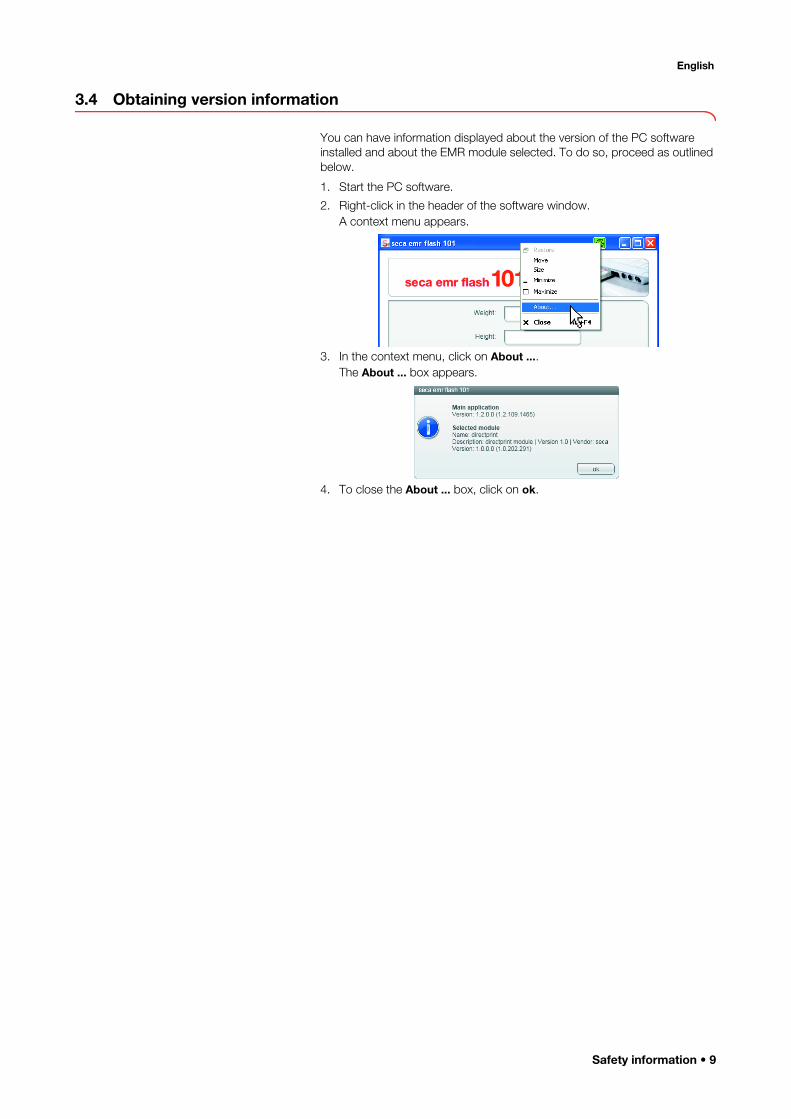
You can have information displayed about the version of the PC software installed and about the EMR module selected. To do so, proceed as outlined below.
1. Start the PC software.
2. Right-click in the header of the software window.A context menu appears.
3. In the context menu, click on About ....The About ... box appears.
4. To close the About ... box, click on ok.
Safety information • 9

4. OVERVIEW
4.1 Main window
1
3
7
9
5
4
2
68
No. Control Function
1 Patient data
Values are entered on measurement:• Weight• HeightData are transmitted from the PDMS to the seca 101 PC software:• Patient ID• First name• Surname• Date of birth• GenderFields containing data transmitted by the PDMS can be displayed or hidden.
2 devices
Show/hide list of devices• « : hide list of devices
• » : show list of devices
3 Available stadiometers
Shows which seca 360° wireless stadiometers are connected to the seca 101 PC software.
4 Selection barShows which devices are selected for measure-ments.
5 settingsConfiguration options for administrators; freely accessible the first time the PC software is started; after that, they can be password-protected
6 cancel• Clears patient data from measuring window• Minimizes the software window
10 •

English
4.2 Settings window
7 send to EMRTransmit measured results to an Electronic Medical Record (EMR) in PDMS
8 helpAccess to:• Administrator's manual• Instructions for use for doctors and assistants
9 Available scalesShows which seca 360° wireless scales are connected to the seca 101 PC software.
No. Control Function
A C DB E
No. Control Function
A general tab
• Configure EMR modules• Assign password• Specify the behavior of the software window• Configure Autosend
B logging tab• Specify which events are logged• Configure logfile
C devices tab• Configure wireless network• Configure RS232 devices
D gui tab• Show/hide patient data fields• Specify weight and height units
E direcptrint tab• Activate and deactivate seca directprint• Configure results report• Specify printer
Overview • 11

4.3 Identification on the packaging
Text/symbol Meaning
Name and address of manufacturer, date of manufacture
Model number
Serial number, consecutive
GALValue in m/s² (verified models)• Gravitational acceleration on earth• Depends on the intended location
ProdID Product identification number, consecutiveApproval Type Type designation of design approval
Follow instructions for use
Device complies with EU directives
Manufacturer's address
Packaging material can be disposed of through recycling programs
12 •
English
5. MANAGING THE SYSTEM
5.1 Starting/exiting the PC software
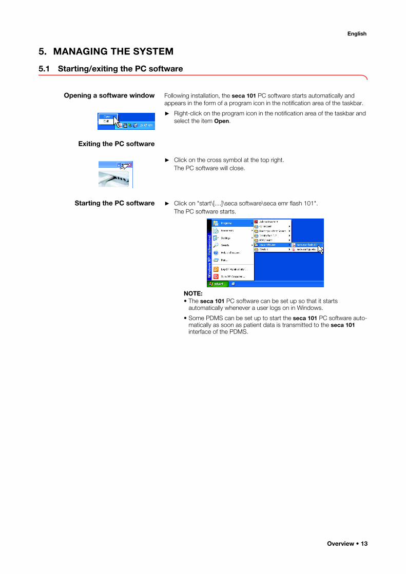
Opening a software window Following installation, the seca 101 PC software starts automatically and appears in the form of a program icon in the notification area of the taskbar.
► Right-click on the program icon in the notification area of the taskbar and select the item Open.
Exiting the PC software
► Click on the cross symbol at the top right.The PC software will close.
Starting the PC software ► Click on "start\[....]\seca software\seca emr flash 101".The PC software starts.
NOTE:• The seca 101 PC software can be set up so that it starts
automatically whenever a user logs on in Windows.
• Some PDMS can be set up to start the seca 101 PC software auto-matically as soon as patient data is transmitted to the seca 101 interface of the PDMS.
Overview • 13

5.2 Making default settings
In the general tab, you can assign a password, specify the behavior of the software window and configure seca EMR modules and the Autosend function.
NOTE:An interface has to be configured on the PDMS for connecting the seca 101 PC software. You can find the configuration instructions for some PDMS on the seca website. Additional configuration instruc-tions are in preparation and will continuously be made available on the seca website. If your PDMS is not there yet, contact its manufacturer for information about connection options.
Assigning a password Users of the software can be allocated two different roles.
• Administrator
• User
The Administrator role is assigned by means of a password. Every user who knows the password can access settings and manage the system.
The roles include the following rights (• = possible, - = not possible):
NOTICE!Malfunction due to incorrect configurationWhen the program is started for the first time after installation, there is no password protection. The settings window is freely accessible.► Assign a password to prevent access by persons without sufficient
expertise.
► Only give the password to persons with sufficient expertise.
Function Administrator UserManage software • -Assign/change password • -Receive patient data from PDMS • •Perform measurement • •Enter measured results • •Send patient data to PDMS • •
14 •
English
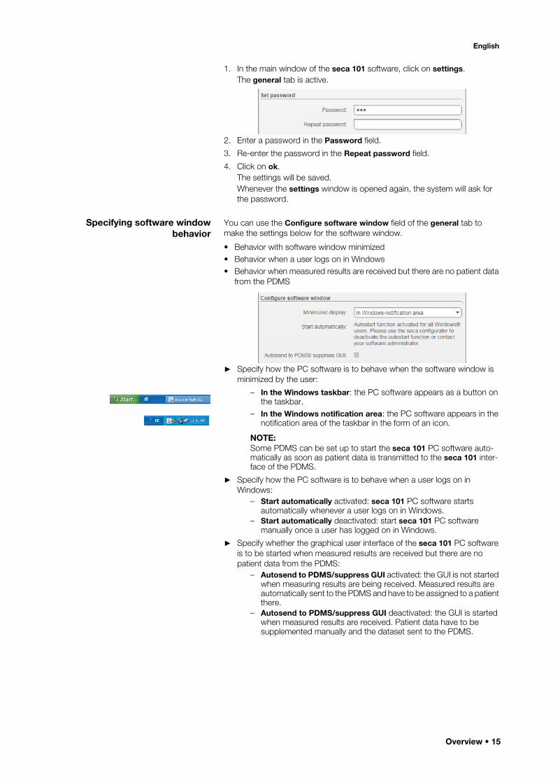
1. In the main window of the seca 101 software, click on settings.The general tab is active.
2. Enter a password in the Password field.
3. Re-enter the password in the Repeat password field.
4. Click on ok.The settings will be saved.Whenever the settings window is opened again, the system will ask for the password.
Specifying software window behavior
You can use the Configure software window field of the general tab to make the settings below for the software window.
• Behavior with software window minimized• Behavior when a user logs on in Windows• Behavior when measured results are received but there are no patient data
from the PDMS
► Specify how the PC software is to behave when the software window is minimized by the user:
– In the Windows taskbar: the PC software appears as a button on the taskbar.
– In the Windows notification area: the PC software appears in the notification area of the taskbar in the form of an icon.
NOTE:Some PDMS can be set up to start the seca 101 PC software auto-matically as soon as patient data is transmitted to the seca 101 inter-face of the PDMS.
► Specify how the PC software is to behave when a user logs on in Windows:
– Start automatically activated: seca 101 PC software starts automatically whenever a user logs on in Windows.
– Start automatically deactivated: start seca 101 PC software manually once a user has logged on in Windows.
► Specify whether the graphical user interface of the seca 101 PC software is to be started when measured results are received but there are no patient data from the PDMS:
– Autosend to PDMS/suppress GUI activated: the GUI is not started when measuring results are being received. Measured results are automatically sent to the PDMS and have to be assigned to a patient there.
– Autosend to PDMS/suppress GUI deactivated: the GUI is started when measured results are received. Patient data have to be supplemented manually and the dataset sent to the PDMS.
Overview • 15

NOTICE!Loss of dataIf you activate the Autosend to PDMS/suppress GUI function, it is not possible to assign measured results to a patient record in the seca 101 PC software. Assignment can only be performed in your PDMS.► Immediately measurement is complete, ensure that the measured
results are assigned to the correct patient in your PDMS.
Setting up Autosend If the seca 101 PC software receives measured results, these can be passed straight on to a PDMS without opening the PC software.
You can set up automatic transmission of measured results to a PDMS in the Initiate Autosend field:
• Select which type of measured result has to be received in order for all measured results to be transmitted automatically.
• Specify whether patient data have to be present in the seca 101 PC software.
► Specify which measured results are to trigger automatic transmission to a PDMS as soon as they are received from the seca 101 PC software:
– Height: As soon as the height result is received, measured results are transmitted to the PDMS.
– Weight: As soon as the weight result is received, measured results are transmitted to the PDMS.
– Height and weight: Only once both measured results have been received are they transmitted to the PDMS.
– Height or weight: As soon as one of the two measured results is received, it is transmitted to the PDMS.
► Specify whether patient data have to be present in the seca 101 PC software in order for measured results to be transmitted to the PDMS automatically.
– Wait for patient data activated: Measured results are only sent to the PDMS automatically if patient data are present in the seca 101 PC software.
– Wait for patient data deactivated: Measured results are sent to the PDMS automatically. Patient data do not have to be present in seca 101.
Transmitting measured results automatically
Example:
Activate the Initiate Autosend function with the following settings:
• Before measured results are transmitted automatically, patient data from the PDMS must be present in the seca 101 PC software.
• The measured result is to be transmitted as soon as Height or weight are received by the seca 101 PC software.
16 •

English
Make the following settings:
1. In the general tab, click on the Height or weight button in Initiate Autosend.
The Initiate Autosend function is activated.
2. Click the Wait for patient data checkbox.
The Wait for patient data function is activated. Measured results are only transmitted if patient data from the PDMS are present in the seca 101 PC software.
Overview • 17

5.3 Configuring modules
Selecting a module In order to be able to transmit measured results to a PDMS using the seca 101 PC software, you need to download and install the relevant integra-tion modules from the seca website. To do so, proceed as outlined below.
1. Download the desired seca EMR integration module package ("*sem.zip") from the seca website.
2. Click on settings in the main window of the seca 101 PC software.
The general tab is active.
3. In the Select EMR module field, click on add (in this case, HL7).
The Open dialog window opens.
4. Select the downloaded seca EMR integration module package ("*sem.zip").
5. Click on Open.The package selected is displayed in the Select EMR module field (in this case, HL7).
NOTE:As an alternative to steps 3. to 5., you can drag the desired file straight from a Windows Explorer window into the Select EMR module field (drag & drop function).To configure the selected module, proceed as described in the sections below.
18 •
English
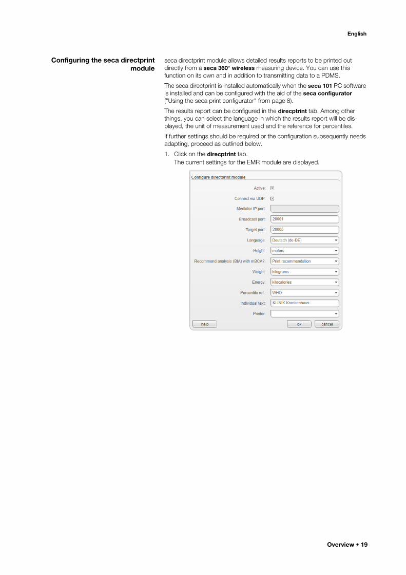
Configuring the seca directprint module
seca directprint module allows detailed results reports to be printed out directly from a seca 360° wireless measuring device. You can use this function on its own and in addition to transmitting data to a PDMS.
The seca directprint is installed automatically when the seca 101 PC software is installed and can be configured with the aid of the seca configurator ("Using the seca print configurator" from page 8).
The results report can be configured in the direcptrint tab. Among other things, you can select the language in which the results report will be dis-played, the unit of measurement used and the reference for percentiles.
If further settings should be required or the configuration subsequently needs adapting, proceed as outlined below.
1. Click on the direcptrint tab.The current settings for the EMR module are displayed.
Overview • 19
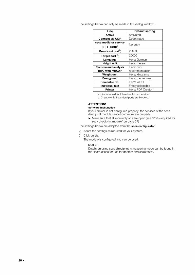
The settings below can only be made in this dialog window.
ATTENTION!Software malfunctionIf your firewall is not configured properly, the services of the seca directprint module cannot communicate properly.► Make sure that all required ports are open (see "Ports required for
seca directprint module" on page 37)
The settings below are adopted from the seca configurator.
2. Adapt the settings as required for your system.
3. Click on ok.The module is configured and can be used.
NOTE:Details on using seca directprint in measuring mode can be found in the "Instructions for use for doctors and assistants".
Line Default settingActive Activated
Connect via UDP Deactivatedseca mediator service
[IP] : [port]:a
a. Line reserved for future function expansion
No entry
Broadcast portb
b. Change only if standard ports are blocked.
20001
Target port b. 20005Language Here: GermanHeight unit Here: meters
Recommend analysis (BIA) with mBCA?
Here: print recommendation
Weight unit Here: kilogramsEnergy unit Here: megajoules
Percentile ref. Here: WHOIndividual text Freely selectable
Printer Here: PDF Creator
20 •
English
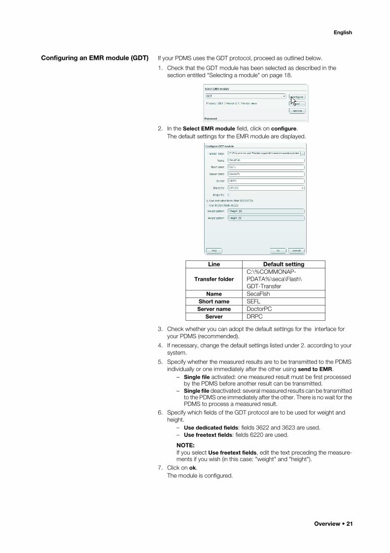
Configuring an EMR module (GDT) If your PDMS uses the GDT protocol, proceed as outlined below.
1. Check that the GDT module has been selected as described in the section entitled "Selecting a module" on page 18.
2. In the Select EMR module field, click on configure.The default settings for the EMR module are displayed.
3. Check whether you can adopt the default settings for the interface for your PDMS (recommended).
4. If necessary, change the default settings listed under 2. according to your system.
5. Specify whether the measured results are to be transmitted to the PDMS individually or one immediately after the other using send to EMR.
– Single file activated: one measured result must be first processed by the PDMS before another result can be transmitted.
– Single file deactivated: several measured results can be transmitted to the PDMS one immediately after the other. There is no wait for the PDMS to process a measured result.
6. Specify which fields of the GDT protocol are to be used for weight and height.
– Use dedicated fields: fields 3622 and 3623 are used.– Use freetext fields: fields 6220 are used.
NOTE:If you select Use freetext fields, edit the text preceding the measure-ments if you wish (in this case: "weight" and "height").
7. Click on ok.The module is configured.
Line Default setting
Transfer folderC:\%COMMONAP-PDATA%\seca\Flash\ GDT-Transfer
Name SecaFlshShort name SEFLServer name DoctorPC
Server DRPC
Overview • 21

8. Configure an interface in your PDMS according to the settings in this sec-tion.
NOTE:• For more information on configuring your EMR module, click on
help.
• You can find configuration instructions for some PDMS at www.seca.com.
• Take note of the user documentation for the PDMS used.
22 •

English
Configuring an EMR module (HL7) If your PDMS uses the HL7 protocol, proceed as outlined below.
1. Check that the HL7 module has been selected as described in the section entitled "Selecting a module" on page 18.
2. In the Select EMR module field, click on configure.The default settings for the EMR module are displayed.
3. Check whether you can adopt the default settings for the interface for your PDMS (recommended).
4. If necessary, change the default settings listed under 1. according to your system.
5. Click on ok.
6. The module is configured.
7. Configure an interface in your PDMS according to the settings in this section.
NOTE:• For more information on configuring your EMR module, click on
help.
• You can find configuration instructions for some PDMS at www.seca.com.
• Take note of the user documentation for the PDMS used.
Line Default settingIP address 127.0.0.1Out port 5000In port 5001Header 0bFooter 1c 0d
Encoding UNICODE UTF-8
Overview • 23
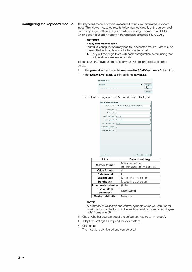
Configuring the keyboard module The keyboard module converts measured results into simulated keyboard input. This allows measured results to be inserted directly at the cursor posi-tion in any target software, e.g. a word-processing program or a PDMS, which does not support common transmission protocols (HL7, GDT).
NOTICE!Faulty data transmissionIndividual configurations may lead to unexpected results. Data may be transmitted with faults or not be transmitted at all.► Carry out thorough tests with each configuration before using that
configuration in measuring mode.
To configure the keyboard module for your system, proceed as outlined below.
1. In the general tab, activate the Autosend to PDMS/suppress GUI option.
2. In the Select EMR module field, click on configure.
The default settings for the EMR module are displayed:
NOTE:A summary of wildcards and control symbols which you can use for configuration can be found in the section "Wildcards and control sym-bols" from page 38.
3. Check whether you can adopt the default settings (recommended).
4. Adapt the settings as required for your system.
5. Click on ok.The module is configured and can be used.
Line Default setting
Master formatMeasurement at {d}:{n}height: {h}, weight: {w}
Value format #Date format tWeight unit Measuring device unitHeight unit Measuring device unit
Line break delimiter {Enter}Use custom delimiter?
Deactivated
Custom delimiter No entry
24 •
English
NOTICE!Software malfunction in measuring modeTransmitted data are converted into keyboard input, so in measuring mode, this may cause the seca 101 PC software or the target software to behave unexpectedly.► Check at the start of measuring that the target software, not the
seca 101 PC software is the active window.
► Ensure when the keyboard module is activated that the send to EMR key is never pressed.
► Follow the instructions in the "Instructions for Use for Doctors and Assistants".
5.4 Setting up logging
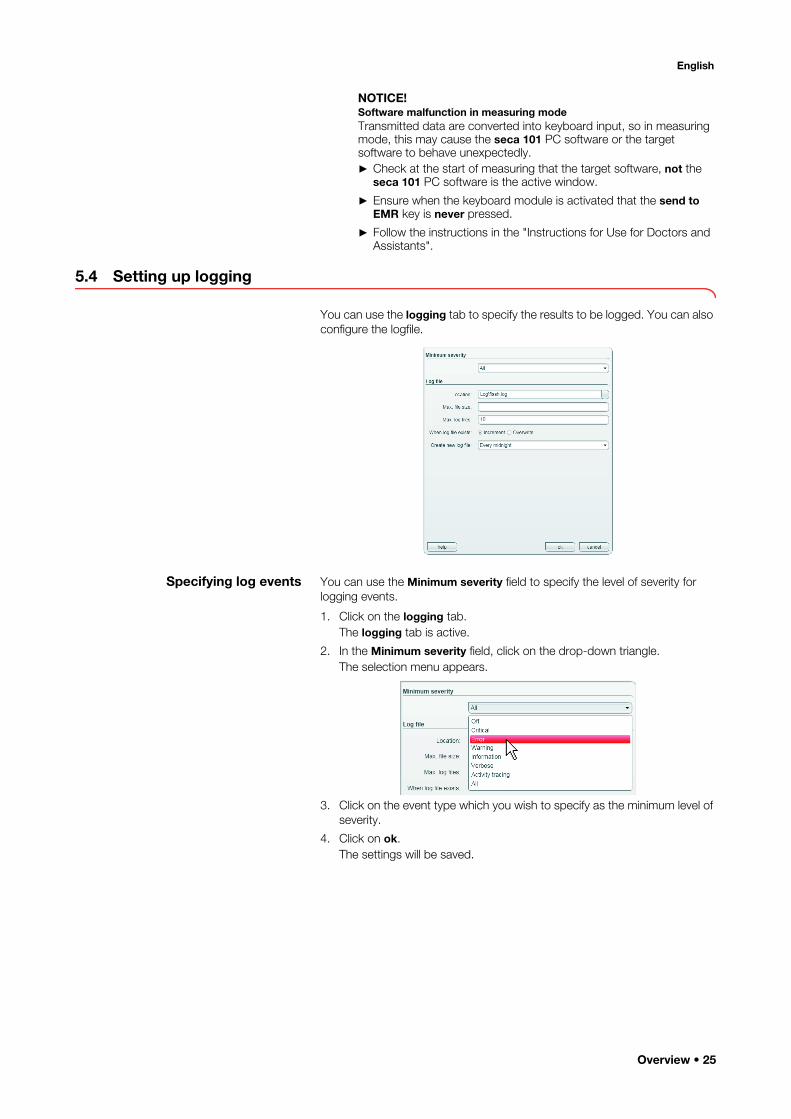
You can use the logging tab to specify the results to be logged. You can also configure the logfile.
Specifying log events You can use the Minimum severity field to specify the level of severity for logging events.
1. Click on the logging tab.The logging tab is active.
2. In the Minimum severity field, click on the drop-down triangle.The selection menu appears.
3. Click on the event type which you wish to specify as the minimum level of severity.
4. Click on ok.The settings will be saved.
Overview • 25

Configuring a logfile You can use the Logfile field to specify whether one or more logfiles are to be created and configure them.
1. Make the following settings in the text fields of the Logfile field:– Storage location– Max. file size– Max. logfiles
2. Specify whether to overwrite an existing logfile or create a new one.– Create new file: new logfiles will be created until the number spec-
ified under Max. logfiles is reached. After this, the oldest logfiles will be overwritten.
– Overwrite file: the existing logfile will be overwritten.3. Specify under Generate new logfile at what times a logfile is to be creat-
ed.
4. Click on ok.The settings will be saved.
Setting New logfileIndependent of
timeLogfiles not created as a function of time
Every minute After one minuteHourly After one hourDaily Every 24 hours
Weekly After one weekMonthly After one monthAnnually After one year
At midnight At midnight
26 •

English
5.5 Connecting measuring devices to the PC software
In the devices tab, you can connect measuring devices to the seca 101 PC software.
• Wirelessly: measuring devices from the seca 360° wireless system (see "Configuring a seca 360° wireless network" from page 27)
• Wired: seca scales with RS232 interface (see "Configuring RS232 devices" from page 30)
Configuring a seca 360° wireless network
You can use the devices tab to make a wireless connection between seca 360° wireless devices and the seca 101 PC software. To do so, you need a seca 360° wireless USB adapter 456.
NOTE:This section describes how to use the PC software. Technical infor-mation about the seca 360° wireless network can be found in the section entitled "The seca 360° wireless network" from page 37.
With a single seca 101 PC workstation and a seca 360° wireless USB adapter 456, it is possible to set up a maximum of three wireless groups.
To do so, proceed as outlined below.
1. Insert the seca 360° wireless USB adapter 456 in a USB port of the PC.The LED on the USB adapter goes red.
2. In the devices tab, click on Wireless devices in the field configure.The configuration window for the wireless network appears.
3. Check that the devices you wish to incorporate in a wireless group are switched off.
Overview • 27

4. In the one of the three wireless groups you want (in this case: wireless group "0"), click on Set up wireless group.
The PC software proposes three channels.
NOTICE!Incorrect device assignment and faulty data transferYou can select channel numbers other than those suggested by the system. This may cause devices to be assigned to incorrect wireless groups and result in unreliable data transfer.► Check that the channel numbers are not being used for the other
two wireless groups.
► Check that in each group, the channel numbers are spaced apart by a value of 30.
5. Click on Start registration.The PC software waits for signals from other wireless-capable seca devices in range.
28 •

English
6. Switch on all devices (e. g.one scale and one stadiometer) you wish to incorporate in a wireless group.When the PC software detects the devices, a beep will be heard.Detected devices are stored on the seca 360° wireless USB adapter 456 and displayed in the PC software.
7. Click on Complete registration.The serial numbers of the devices detected are displayed under SN.
8. If desired, repeat steps 4. to 7. for the other two wireless groups.
9. Click on close.The configuration window for the wireless network closes.
10. Switch off all devices which have been successfully registered if you do not immediately need them for measurements.
Overview • 29

Configuring RS232 devices To use seca scales with an RS232 interface, proceed as outlined below.
1. Connect the device to the PC.
NOTE:• The maximum number of scales with an RS232 interface depends
on the number of COM ports of the PC used.
• Follow the instructions for use for the device in question.
2. In the devices tab, click on add in the Scales with a serial interface field.The configuration line for port COM1 appears.
3. Click on edit.The configuration line is activated. It can be edited.
4. In the configuration line, click on the Description column.
5. In the Description column, enter a description of the scale (recommended: model and setup location).
6. In the Model column, click on the selection triangle.
A drop-down menu appears.
30 •

English
7. Click on the desired menu item:– seca model: if seca model known– Weight only: scale has no BMI function, seca model unknown– Weight and height: scale has BMI function, seca model unknown
Setting appears in the Model column.The drop-down menu closes.
8. If desired, repeat steps 1. to 7. for other seca scales with RS232 interface.
9. Click on ok.The dialog window closes.The scale is shown in the main window (see "Main window" from page 10) in line with the table below.
NOTICE!Malfunction in measuring modeMeasured data can only be transmitted to the seca 101 PC software if the PC to which the measuring device in question is connected is switched on.► Before each measuring step, check that the PC to which the
measuring device is connected is switched on.
NOTICE!Loss of dataIf there is no input for approx. 10 minutes, partial results are discarded.► Measure one patient's weight and height immediately
consecutively.
Setting in devices tab in
Model column
Available scales
Available stadiometers
seca scale without BMI function
• -
seca scale with BMI function
• •
Weight only • -Weight and height • •
Overview • 31

Managing measuring devices You can view which scales and stadiometers are connected to your PC. As an administrator, you can edit the configuration. Devices are differentiated according to weight or height measurement.
The information below is displayed for the individual components.
• Interface: COM port (RS232 devices)/wireless group (seca 360° wireless devices)
• Device type e. g. personal scale (completed automatically when the seca 360° wireless system is configured).
• Description: can be edited, seca recommends in this case entering the model number of the device, e. g. seca 285, and the setup location.
• Serial number (completed automatically when the seca 360° wireless sys-tem is configured).
To edit the device configuration, proceed as outlined below.
1. In the settings window, click on the device you wish to edit.The selection bar is positioned on the device selected.
2. Click on edit.An insertion point will appear in the Description field.
3. Enter a device description (e. g. device name and setup location).
4. Click on ok.The settings will be saved.
32 •

English
5.6 Setting up the user interface
You can make the following settings in the gui tab:
• specify font size for displaying measured results• specify entry fields visible to the user• specify the units for displaying measured results
Specifying font size for measurements
You can specify the font size for displaying measured results in the main window. To do so, proceed as outlined below.
1. Click on the gui tab.
2. Click in the Font for measurements field.
3. Enter the desired font size (8 - 120 pt).
NOTE:If imperial units are set, fractions will be shown in the form "3/8" only from a minimum font size of 11 pt. At smaller font sizes, fractions will be displayed in the form "3/8".
4. Click on ok.The settings will be saved.The deactivated entry fields will no longer be displayed in the main window.
Showing/hiding entry fields for patient data
With some PDMS it is not possible to add patient data to all entry fields visible in the seca 101 PC software. You have the option in the seca 101 PC software of hiding all entry fields your PDMS cannot complete.
Following initial installation of the PC software, all entry fields are activated for patient data in the gui tab and displayed in the main window of the seca 101 software:
• ID
• First name• Surname• Date of birth
• Gender
To hide individual entry fields, proceed as outlined below.
Overview • 33
1. Click on the gui tab.
2. Deactivate the checkbox of the entry field you wish to hide.
3. Repeat step 2. for all other entry fields you wish to hide.
4. Click on ok.The settings will be saved.The deactivated entry fields will no longer be displayed in the main window.
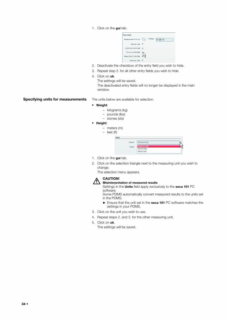
Specifying units for measurements The units below are available for selection.
• Weight:– kilograms (kg)– pounds (lbs)– stones (sts)
• Height:– meters (m)– feet (ft)
1. Click on the gui tab.
2. Click on the selection triangle next to the measuring unit you wish to change.The selection menu appears.
CAUTION!Misinterpretation of measured resultsSettings in the Units field apply exclusively to the seca 101 PC software.Some PDMS automatically convert measured results to the units set in the PDMS.► Ensure that the unit set in the seca 101 PC software matches the
settings in your PDMS.
3. Click on the unit you wish to use.
4. Repeat steps 2. and 3. for the other measuring unit.
5. Click on ok.The settings will be saved.
34 •
English
5.7 Working in the software window
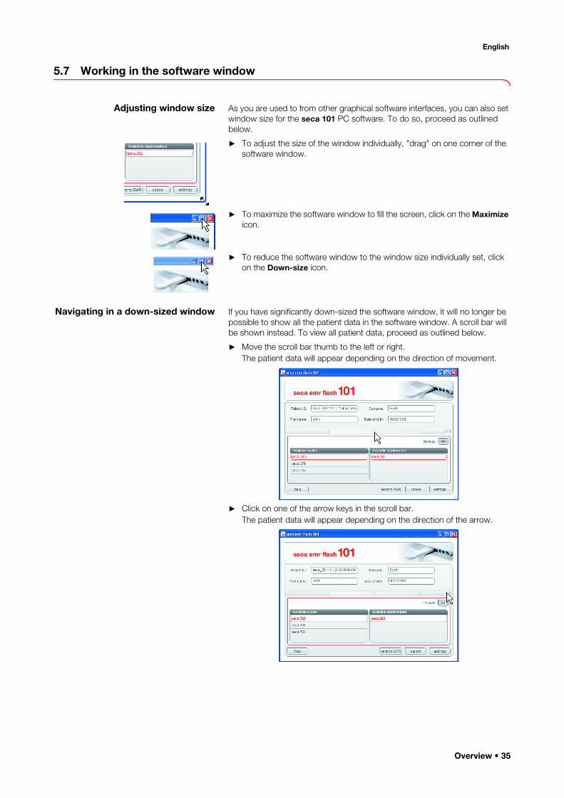
Adjusting window size As you are used to from other graphical software interfaces, you can also set window size for the seca 101 PC software. To do so, proceed as outlined below.
► To adjust the size of the window individually, "drag" on one corner of the software window.
► To maximize the software window to fill the screen, click on the Maximize icon.
► To reduce the software window to the window size individually set, click on the Down-size icon.
Navigating in a down-sized window If you have significantly down-sized the software window, it will no longer be possible to show all the patient data in the software window. A scroll bar will be shown instead. To view all patient data, proceed as outlined below.
► Move the scroll bar thumb to the left or right.The patient data will appear depending on the direction of movement.
► Click on one of the arrow keys in the scroll bar.The patient data will appear depending on the direction of the arrow.
Overview • 35
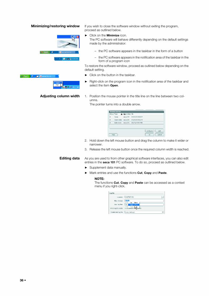
Minimizing/restoring window If you wish to close the software window without exiting the program, proceed as outlined below.
► Click on the Minimize icon.The PC software will behave differently depending on the default settings made by the administrator:
– the PC software appears in the taskbar in the form of a button
– the PC software appears in the notification area of the taskbar in the form of a program icon
To restore the software window, proceed as outlined below depending on the default setting.
► Click on the button in the taskbar.
► Right-click on the program icon in the notification area of the taskbar and select the item Open.
Adjusting column width 1. Position the mouse pointer in the title line on the line between two col-umns.The pointer turns into a double arrow.
2. Hold down the left mouse button and drag the column to make it wider or narrower.
3. Release the left mouse button once the required column width is reached.
Editing data As you are used to from other graphical software interfaces, you can also edit entries in the seca 101 PC software. To do so, proceed as outlined below.
► Supplement data manually.
► Mark entries and use the functions Cut, Copy and Paste.
NOTE:The functions Cut, Copy and Paste can be accessed as a context menu if you right-click.
36 •

English
6. TECHNICAL INFORMATION
6.1 The seca 360° wireless network
NOTICE!Malfunction if USB adapters are confusedIf USB adapters are inadvertently used on a PC workstation other than the original seca 101 PC workstation, the data stored on the USB adapter and in the PC software will conflict. The PC software and the measuring devices will then be unable to communicate with each other.– Make sure that USB adapters are always used on the same PC
workstation.– Secure the USB adapter from inadvertent removal from the USB
port on the PC (see instructions for use of USB adapter).
6.2 Ports required for seca directprint module
The seca directprint module comprises a number of services. To enable com-munication between these services the following ports must be open in your system's firewall:
seca 360° wirelessMaximum number of wireless groups per PC workstation and USB adapter
3
Maximum configuration per wireless group
1 baby scale1 measuring station (or 1 personal scale and
1 length measuring device)1 seca wireless printer (not in conjunction with
this PC software)1 PC with seca 360° wireless
USB adapter 456 and seca 101 PC softwareNumber of channels per wireless group 3
Type of channel assignmentAutomatic (recommended)
ManualChannel numbers 0 - 99Minimum spacing of channel numbers 30• Frequency band• Transmission power• Maximum range
2.433 GHz - 2.480 GHz< 10 mW
10 m
Protocol Port ServiceTCP/UDP 20001 seca mediator serviceTCP/UDP 20002 seca calculation serviceTCP/UDP 20003 seca image serviceTCP/UDP 20004 seca document print service
Overview • 37

6.3 Wildcards and control symbols
This section contains wildcards and control symbols which you can use to configure data transmission via the keyboard module.
Master format Any free text can be entered in the Master format line. You can use the wildcards below in the free text.
Weight and height formats Formats for wildcards {w} and {h} in Master format:
Date formats Formats for date wildcards {d} in Master format
Other formats for date wildcards {d} in Master format
Wildcard Meaning{w} Measured weight{h} Measured height{d} Date according to operating system{n} Line break delimiter
Symbol Meaning0 Wildcard for 0# Wildcard for number. Thousands delimiter, Decimal delimiter,. Integral multiple of 1,000% Value in percente Wildcard for exponent
Symbol Meaningd 8/27/2012 D Monday, August 27, 2012t 2:38 PMT 2:38:08 PMf Monday, August 27, 2012 2:38 PMF Monday, August 27, 2012 2:38:08 PMg 8/27/2012 2:38 PMG 8/27/2012 2:38:08 PM M August 27 r Mon, 27 Aug 2012 14:38:08 GMTs 2012-08-27T14:38:08 u 2012-08-27 14:38:08ZU Monday, August 27, 2012 12:38:08 PMY August, 2012
Symbol Meaning Displaydd Day 27
ddd Day name (shortened) Mondddd Day name (full) Monday
gg Era A.D.hh Hour (2 digits) 02HH Hour (2 digits, 24) 14mm Minute 38MM Month 08
MMM Month name (shortened) AugMMMM Month name (full) August
ss Second 08tt AM or PM (if applicable) PMyy Year (2 digits) 12
38 •

English
Line breaks The line break delimiters below are available in the drop-down menu of seca directprint.
If the wildcards offered in the drop-down menu do not work, you can use the wildcards below in the Custom delimiter line of seca directprint.
Other control symbols
7. WARRANTYPlease note that this PC software is subject to restrictions on the warranty which may arise in conjunction with the license, for example. The warranty restrictions can be called up at www.seca.com.
yyyy Year (4 digits) 2012zz Time zone (short) +02zzz Time zone (long) +02:00
Symbol Meaning Display
Wildcard Meaning{Enter} Simulates the Enter key{Tab} Simulates the Tab key
\n Line break (Unix environment)\r\n Line break (Windows)
Control symbol Meaning+ Shift key^ Ctrl key% Alt key
Wildcard Meaning\t Horizontal tab\v Vertical tab
\rLine break (Mac OS up to version 9)
\b Back key\f Paper feed (printer)
Warranty • 39

17-1
0-01
-253
-002
c_01
-201
9B