SEC Signature Process Gas Analyzer
16
SEC Signature Process Gas Analyzer Instruction and Operation Manual Sensor Electronics Corporation 5500 Lincoln Drive Minneapolis, Minnesota 55436 USA (952) 938-9486 Fax (952) 938-9617 email [email protected] or www.sensorelectronics.com Part Number 71-3000 Rev 4
Transcript of SEC Signature Process Gas Analyzer
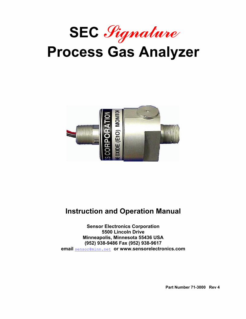
SEC Signature Process Gas Analyzer
Instruction and Operation Manual
Sensor Electronics Corporation 5500 Lincoln Drive
Minneapolis, Minnesota 55436 USA (952) 938-9486 Fax (952) 938-9617
email [email protected] or www.sensorelectronics.com
Part Number 71-3000 Rev 4

Sensor Electronics Corporation
Sensor Electronics Corporation (SEC) is an innovative manufacturer of fixed system gas detection equipment, for combustible gases, oxygen and toxic gases.
Commitment Our quality and service are uncompromising. We back each of our products with a two-year warranty on all materials and workmanship. We offer technical support, user training and on-site service and maintenance of equipment to meet the needs of our customers.
Gas Detection Service
Individually designed maintenance packages are available for specific customer needs. Service begins with verification of the system installation that includes an initial system check and calibration. We then offer customer training programs (on-site and at factory) to insure that technical personnel fully understand operation and maintenance procedures. When on-the-spot assistance is required, service representatives are available to handle any questions or problems immediately.
Warranty
Sensor Electronics Corporation (SEC) warrants products manufactured by SEC to be free from defects in workmanship and materials for a period of two (2) years from date of shipment from the factory. Any parts returned freight pre-paid to the factory and found defective within the warranty would be repaired or replaced, at SEC's option. SEC will return repaired or replaced equipment pre-paid lowest cost freight. This warranty does not apply to items, which by their nature are subject to deterioration or consumption in normal service. Such items may include: Fuses and Batteries. Warranty is voided by abuse including rough handling, mechanical damage, alteration or repair. This warranty covers the full extent of SEC liability and SEC is not responsible for removal, replacement costs, local repair costs, transportation costs or contingent expenses incurred without prior written approval. Sensor Electronics Corporation's obligation under this warranty shall be limited to repair or replacement of any product that has been returned to Sensor Electronics Corporation for warranty consideration. This warranty is expressly in lieu of any and all other warranties expressed or implied, and all other obligations or liabilities on the part of Sensor Electronics Corporation including but not limited to, the fitness for a particular purpose. In no event shall Sensor Electronics Corporation be liable for direct, incidental, or consequential loss or damage of any kind connected with the use of it's products or failure to function or operate properly.
Year 2000 Compliance
All Sensor Electronics products have been tested and are certified by Sensor Electronics to accurately process date/time and date/time related data from, into and between the 20th and 21st centuries. Sensor Electronics products neither contain nor create any logical or mathematical inconsistency, will not malfunction, and will not cease to function when processing date/time data. Please contact Sensor Electronics for further information.

Table of Contents I. SPECIFICATIONS Declaration of Conformity II. GENERAL DESCRIPTION Features Theory of Operation III. INSTALLATION Mechanical Electrical IV. CALIBRATION / OPERATION Zeroing Warm Up Normal Spanning Calibration Certification V. PARTS LIST VI. DRAWING SECTION Figure 1 Overall Layout
Figure 2 Wiring Diagram Figure 3 Block Wiring Diagram Figure 4 Mechanical Diagram
Figure 5 Sensor Separation Kit
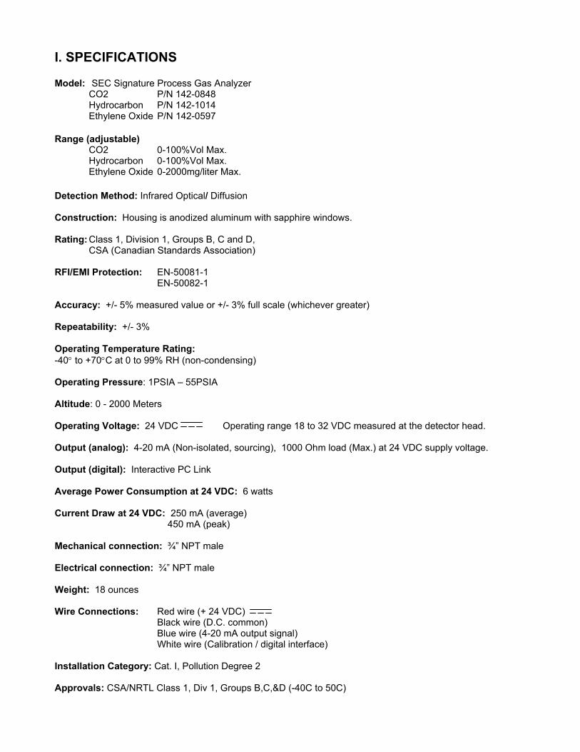
I. SPECIFICATIONS Model: SEC Signature Process Gas Analyzer CO2 P/N 142-0848 Hydrocarbon P/N 142-1014 Ethylene Oxide P/N 142-0597 Range (adjustable) CO2 0-100%Vol Max. Hydrocarbon 0-100%Vol Max. Ethylene Oxide 0-2000mg/liter Max. Detection Method: Infrared Optical/ Diffusion Construction: Housing is anodized aluminum with sapphire windows. Rating: Class 1, Division 1, Groups B, C and D,
CSA (Canadian Standards Association) RFI/EMI Protection: EN-50081-1
EN-50082-1 Accuracy: +/- 5% measured value or +/- 3% full scale (whichever greater) Repeatability: +/- 3% Operating Temperature Rating: -40° to +70°C at 0 to 99% RH (non-condensing) Operating Pressure: 1PSIA – 55PSIA Altitude: 0 - 2000 Meters Operating Voltage: 24 VDC Operating range 18 to 32 VDC measured at the detector head. Output (analog): 4-20 mA (Non-isolated, sourcing), 1000 Ohm load (Max.) at 24 VDC supply voltage. Output (digital): Interactive PC Link Average Power Consumption at 24 VDC: 6 watts Current Draw at 24 VDC: 250 mA (average) 450 mA (peak) Mechanical connection: ¾” NPT male Electrical connection: ¾” NPT male Weight: 18 ounces Wire Connections: Red wire (+ 24 VDC)
Black wire (D.C. common) Blue wire (4-20 mA output signal) White wire (Calibration / digital interface)
Installation Category: Cat. I, Pollution Degree 2 Approvals: CSA/NRTL Class 1, Div 1, Groups B,C,&D (-40C to 50C)
Declaration of Conformity
Sensor Electronics Corporation 5500 Lincoln Drive Minneapolis, Minnesota 55436 USA Telephone: 952.938.9486 Fax: 952.938.9617 Email: [email protected] Type of Equipment: SEC Signature Process Analyzer SEC IR PC Link Model Number: SEC Signature Process Analyzer - Part Number 142-0597 SEC IR PC Link - Part Number 142-0636 I hereby declare that the equipment specified above conforms to the protection requirements of the EC DIRECTIVE 89/336/EEC on Electromagnetic Compatibility (EMC), in accordance with the provisions of the Electromagnetic Compatibility Regulations 1992. The following standards have been applied:
EN 50081 –1 Emissions Standard (Residential Commercial and Light Industry)
EN 50082 –1
Immunity Standard (Residential Commercial and Light Industry) Signature ______________________________ Patrick G. Smith Director of Engineering Date: August 6, 2001

II. GENERAL DESCRIPTION CONVENTIONS
The following conventions are used in this manual. Warning Statement VDC (DC Voltage)
! The SEC Signature Process Analyzer is a
microprocessor based intelligent device that continuously measures levels of gas in process applications.
Theory of Operation The SEC Signature Process Analyzer uses infrared absorption technology to identify and measure gas concentrations. Gases absorb infrared light at certain wavelengths due to molecular resonance. Since each gas has a unique molecular structure, each causes a unique light absorption signature. The Signature Process Analyzer measures light absorption at critical wavelengths and uses embedded algorithms to quantify the concentration. The SEC Signature Process Analyzer uses an infrared light source at one
The SEC Signature Process Analyzer is a stand-alone device providing a 4 to 20 mA signal corresponding to actual concentrations of the process gas being measured. Features • Requires minimal routine calibration to ensure
proper operation. end of the optical path and an infrared light sensor at the opposite end. The reliable optical system and lack of delicate components such as beam splitters and mirrors make the Signature Process Analyzer very stable and robust in harsh process environments.
• Continuous self-test automatically indicates a
fault, with fail to safe operation. • A multi-layered filtering system protects optics
from dirt and water ingress. The SEC Signature Process Analyzer utilizes a
unique Automatic Analog Control circuit, the AutoAC circuit (Patented). The AutoAC continuously makes adjustments to null out effects from temperature, component drift, dirty optics, interferents and aging. These adjustments are made according to algorithms derived from infrared gas absorption theory. The AutoAC circuit is continuously checking all unit operating parameters. If any parameter goes out of tolerance, the AutoAC circuit sets a fault code appropriate to the problem. The AutoAC circuit ensures that once the unit is spanned, it will remain accurate as long as the zero is accurate. Simply calibrate (span one time) the unit with a specific amount of gas and the device will accurately track
• Straight optical path eliminates the need for mirrors, reflective surfaces or beam splitters thereby increasing the stability and reducing the maintenance of the device.
• Discourages condensation interference by
internally heating optical chamber. • Standard 4 to 20 mA output (current sourcing). • Explosion proof housing designed for duty in
harsh environments. • Smart Calibration AutoAC circuit.
in-process gas concentrations. The only ongoing calibration that is necessary is an occasional zero.
• No routine maintenance required
III. INSTALLATION
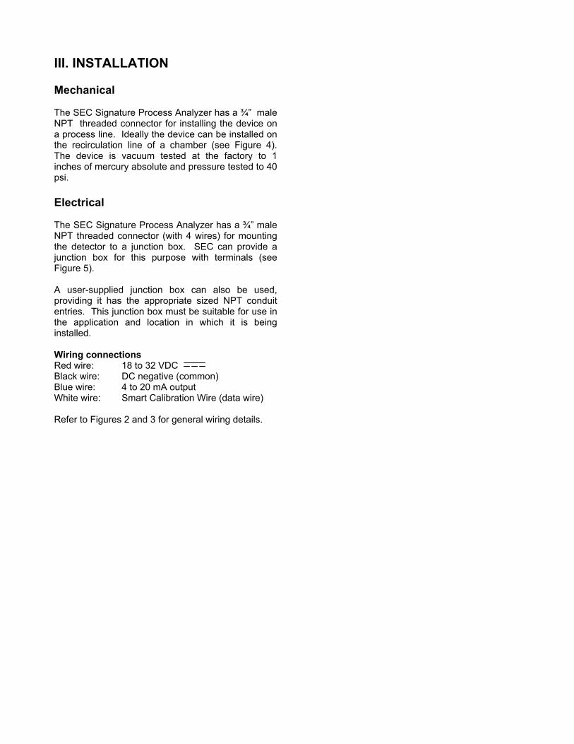
Mechanical The SEC Signature Process Analyzer has a ¾” male NPT threaded connector for installing the device on a process line. Ideally the device can be installed on the recirculation line of a chamber (see Figure 4). The device is vacuum tested at the factory to 1 inches of mercury absolute and pressure tested to 40 psi.
Electrical
The SEC Signature Process Analyzer has a ¾” male
NPT threaded connector (with 4 wires) for mounting the detector to a junction box. SEC can provide a junction box for this purpose with terminals (see Figure 5).
A user-supplied junction box can also be used,
providing it has the appropriate sized NPT conduit entries. This junction box must be suitable for use in the application and location in which it is being installed.
Wiring connections Red wire: 18 to 32 VDC Black wire: DC negative (common) Blue wire: 4 to 20 mA output White wire: Smart Calibration Wire (data wire) Refer to Figures 2 and 3 for general wiring details.

Insulator The SEC Signature Process Gas Analyzer’s internal temperature should be at least 10º F warmer than the process temperature to discourage condensation on the optical surfaces. The Signature Process Gas Analyzer is internally heated but mounting the device to a cold surface can draw significant heat from the Signature Process Gas Analyzer. The internal temperature of the Signature Process Gas Analyzer can be monitored using the SEC IR PC LINK software package.
Before insulator is installed
If the internal temperature is not 10º F above the process temperature, a simple insulator (SEC supplied) can be installed around the Signature Process Gas Analyzer to help retain heat.
Insulator installed
I
ZZon Siwstssizea Nuo C Ts
V. CALIBRATION / OPERATIONWarning: The user shall be made aware that if the equipment is used in a manner not specified by the manufacturer, the protection provided by the equipment may be impaired.
eroing eroing the SEC Signature Process Analyzer is the nly regular calibration (maintenance) operation ormally required.
EC Signature Process Analyzer zero calibration is nitiated by connecting the calibration lead (white ire) to the negative lead (DC common) of the power upply for ten (10) seconds and releasing. Although his can be accomplished manually, installation of a witch is recommended. It is recommended that this witch be a momentary type switch to prevent it from
nadvertently being left in the calibrate position. The ero calibration operation is initiated at the rising dge (releasing). The zero initiation can be verified t on the 4 to 20 mA output (2.2 mA)
ote: For best accuracy, the unit should be powered p for at least 30 minutes before any calibration peration. urrent Output and Corresponding Status Table
he 4 to 20 mA output is a non-isolated current ource.
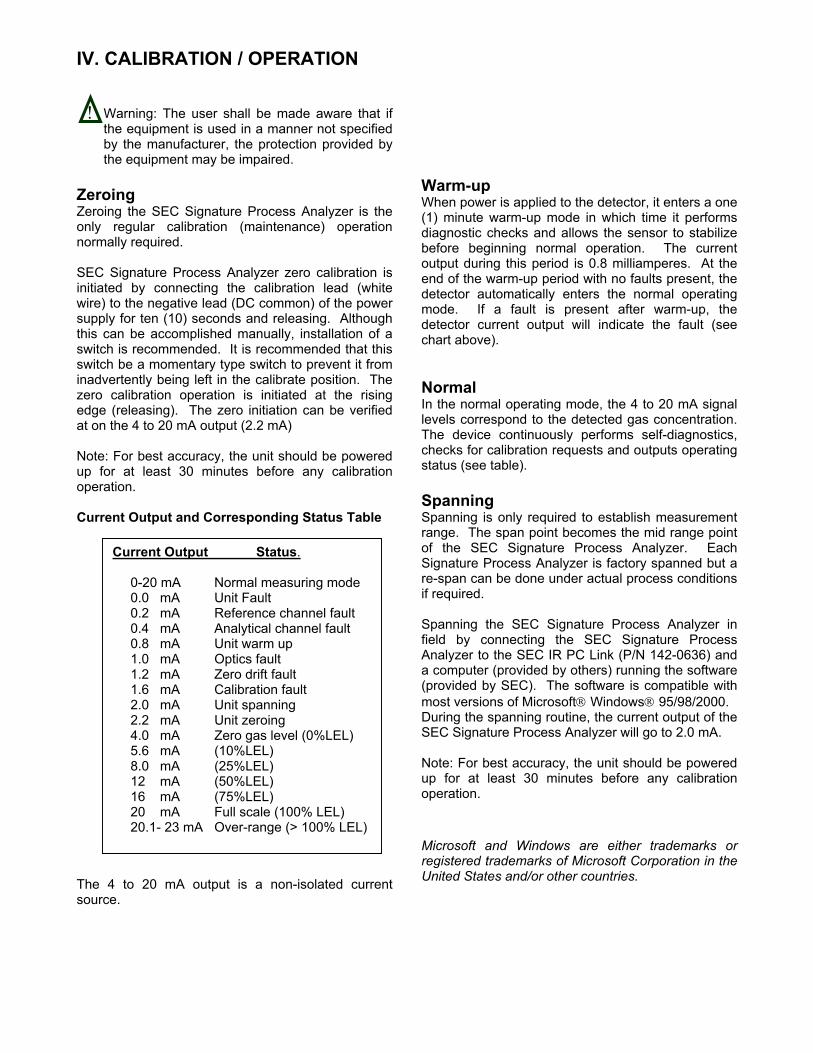
! Warm-up When power is applied to the detector, it enters a one (1) minute warm-up mode in which time it performs diagnostic checks and allows the sensor to stabilize before beginning normal operation. The current output during this period is 0.8 milliamperes. At the end of the warm-up period with no faults present, the detector automatically enters the normal operating mode. If a fault is present after warm-up, the detector current output will indicate the fault (see chart above). Normal In the normal operating mode, the 4 to 20 mA signal levels correspond to the detected gas concentration. The device continuously performs self-diagnostics, checks for calibration requests and outputs operating status (see table). Spanning Spanning is only required to establish measurement range. The span point becomes the mid range point of the SEC Signature Process Analyzer. Each Signature Process Analyzer is factory spanned but a re-span can be done under actual process conditions if required.
Current Output Status. 0-20 mA Normal measuring mode 0.0 mA Unit Fault 0.2 mA Reference channel fault 0.4 mA Analytical channel fault 0.8 mA Unit warm up 1.0 mA Optics fault 1.2 mA Zero drift fault 1.6 mA Calibration fault 2.0 mA Unit spanning 2.2 mA Unit zeroing 4.0 mA Zero gas level (0%LEL) 5.6 mA (10%LEL) 8.0 mA (25%LEL) 12 mA (50%LEL) 16 mA (75%LEL) 20 mA Full scale (100% LEL) 20.1- 23 mA Over-range (> 100% LEL)
Spanning the SEC Signature Process Analyzer in field by connecting the SEC Signature Process Analyzer to the SEC IR PC Link (P/N 142-0636) and a computer (provided by others) running the software (provided by SEC). The software is compatible with most versions of Microsoft Windows 95/98/2000. During the spanning routine, the current output of the SEC Signature Process Analyzer will go to 2.0 mA. Note: For best accuracy, the unit should be powered up for at least 30 minutes before any calibration operation. Microsoft and Windows are either trademarks or registered trademarks of Microsoft Corporation in the United States and/or other countries.

V. PARTS LIST Part Number Description 142-0636 SEC IR PC Link Kit 142-1022 Replacement Filter Kit 142-0876 Insulator 190-1000 SEC 2001 Explosion proof junction box

VI. DRAWING SECTION Figure # Title Figure 1 Overall Layout Figure 2 Wiring Diagram Figure 3 Block Wiring Diagram Figure 4 Mechanical Diagram Figure 5 Sensor Separation Kit

3/4" NPT 2.75" DIA.3/4" NPT
2.80"
OVERALL LAYOUT SEC Signature Process
Analyzer
FIGURE 1
Sensor Electronics Corporation 5500 Lincoln Drive
Minneapolis, MN 55436 Tel: (952) 938-9486 Fax: (952) 938-9617
e-mail: [email protected]
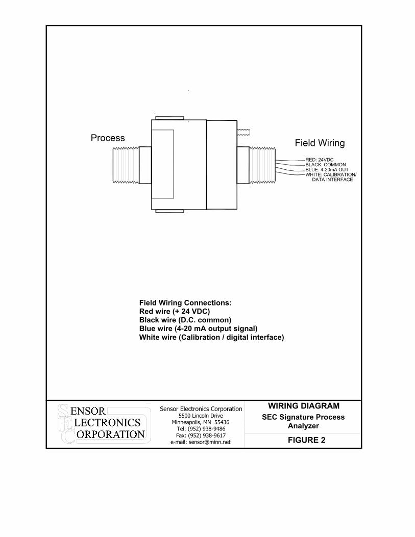
BLACK: COMMONBLUE: 4-20mA OUTWHITE: CALIBRATION/ DATA INTERFACE
RED: 24VDC
Field WiringProcess
Sensor Electronics Corporation 5500 Lincoln Drive
Minneapolis, MN 55436 Tel: (952) 938-9486 Fax: (952) 938-9617
e-mail: [email protected]
WIRING DIAGRAM SEC Signature Process
Analyzer FIGURE 2
Field Wiring Connections: Red wire (+ 24 VDC) Black wire (D.C. common) Blue wire (4-20 mA output signal) White wire (Calibration / digital interface)
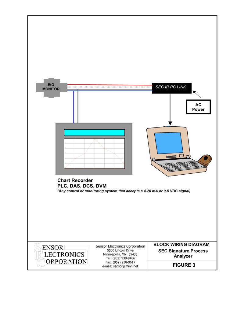
FIGURE 3
SEC Signature Process Analyzer
BLOCK WIRING DIAGRAM Sensor Electronics Corporation 5500 Lincoln Drive
Minneapolis, MN 55436 Tel: (952) 938-9486 Fax: (952) 938-9617
e-mail: [email protected]
EtO MONITOR
AC Power
SEC IR PC LINK
Chart Recorder PLC, DAS, DCS, DVM (Any control or monitoring system that accepts a 4-20 mA or 0-5 VDC signal)
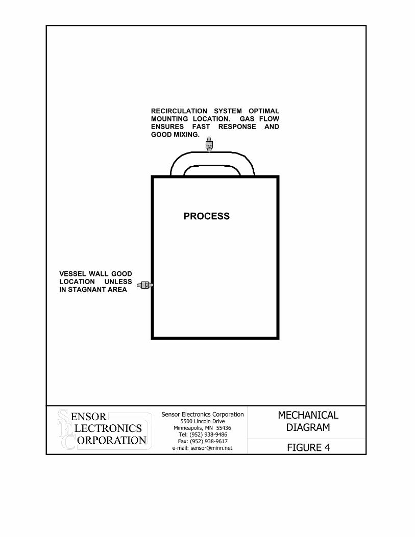
FIGURE 4
MECHANICAL DIAGRAM
RECIRCULATION SYSTEM OPTIMALMOUNTING LOCATION. GAS FLOWENSURES FAST RESPONSE ANDGOOD MIXING.
PROCESS
VESSEL WALL GOOD LOCATION UNLESS IN STAGNANT AREA
Sensor Electronics Corporation 5500 Lincoln Drive
Minneapolis, MN 55436 Tel: (952) 938-9486 Fax: (952) 938-9617
e-mail: [email protected]
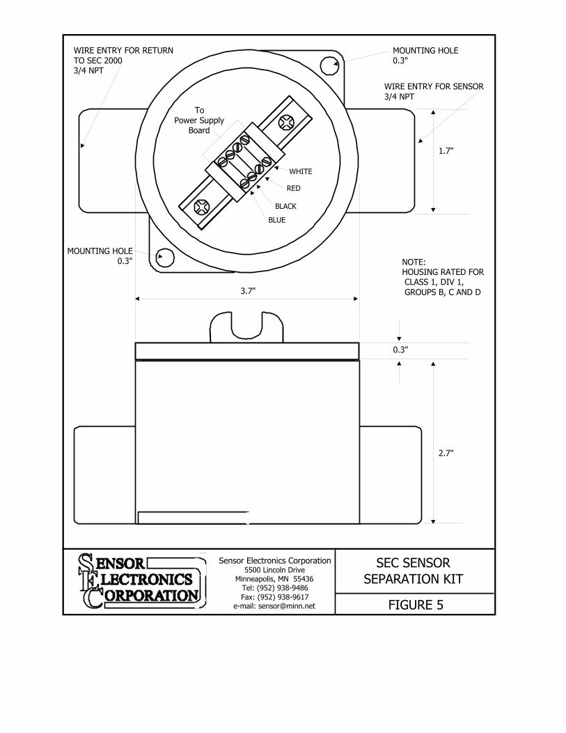
BLUE
To Power Supply
Board
BLACK
RED
WHITE
MOUNTING HOLE 0.3"
MOUNTING HOLE 0.3"
1.7"
0.3"
2.7"
3.7"
FIGURE 5
SEC SENSOR
SEPARATION KIT
NOTE: HOUSING RATED FOR CLASS 1, DIV 1, GROUPS B, C AND D
WIRE ENTRY FOR RETURN TO SEC 2000 3/4 NPT
WIRE ENTRY FOR SENSOR 3/4 NPT
Sensor Electronics Corporation 5500 Lincoln Drive
Minneapolis, MN 55436 Tel: (952) 938-9486 Fax: (952) 938-9617
e-mail: [email protected]