Seal assembly and disassembly guidelines (Kalsi Seals ...€¦ · Seal assembly and disassembly...
22
Revision 5 September 20, 2017 Individual chapters of the Kalsi Seals Handbook are periodically updated. To determine if a newer revision of this chapter exists, please visit www.kalsi.com/seal-handbook.htm. NOTICE: The information in this chapter is provided under the terms and conditions of the Offer of Sale, Disclaimer, and other notices provided in the front matter of this handbook. Document 3090 © 2017 Kalsi Engineering, Inc. All rights reserved. Kalsi Seals Handbook Chapter D19 Seal assembly and disassembly guidelines
-
Upload
phunghuong -
Category
Documents
-
view
230 -
download
1
Transcript of Seal assembly and disassembly guidelines (Kalsi Seals ...€¦ · Seal assembly and disassembly...
Revision 5 September 20, 2017
Individual chapters of the Kalsi Seals Handbook are periodically updated. To determine if
a newer revision of this chapter exists, please visit www.kalsi.com/seal-handbook.htm.
NOTICE: The information in this chapter is provided under the terms and conditions of the Offer of
Sale, Disclaimer, and other notices provided in the front matter of this handbook.
Document 3090 © 2017 Kalsi Engineering, Inc. All rights reserved.
Kalsi Seals Handbook
Chapter D19
Seal assembly and disassembly guidelines

Seal assembly and disassembly guidelines Chapter D19 Page 1
Search this handbook Contact Kalsi Engineering
1. Introduction
This chapter provides general guidelines for assembly and disassembly with typical
solid cross-section, direct compression-type1 Kalsi Seals. Not all seal applications are
alike, and modified procedures may be necessary for your specific equipment and seal
characteristics.
Retrain periodically
Periodically retraining assembly personnel is important, to keep them well versed in
proper procedures, and aware of the consequences of improper component handling,
assembly, and lubricant filling.
2. Rotary seal storage / age control / shelf life
1. To maximize shelf life2, store Kalsi Seals away from ultra-violet light and direct
sunlight at temperatures less than 120°F (48.9°C) in a location away from radiation
and heat sources (registers, radiators, etc.), and away from electric motors and other
ozone sources. Elastomer deterioration increases with increasing temperature. The
ideal storage temperature is 40 to 80°F (4.4 to 26.7°C), with a relative humidity of
25 to 65%. Avoid very moist or dry storage conditions. To ease handling, seals that
have been stored at cold temperature should be warmed to room temperature before
installation.
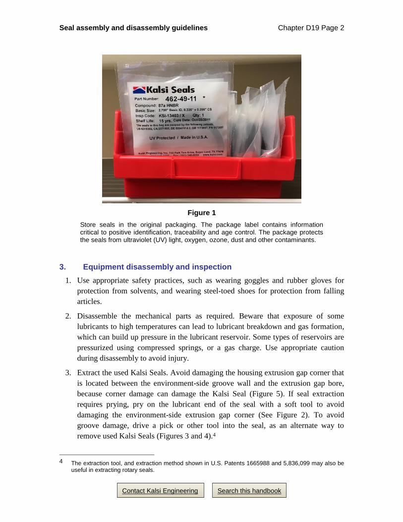
2. Store seals in the original packaging (Figure 1), to protect the seals from ultra-violet
light,3 oxygen, ozone, dust and other contaminants, and to maintain positive
identification and traceability. (The inspection code provides traceability to seal
inspection and batch documentation.) The seal package also provides the cure date
and recommended shelf life.
3. Store seals in a relaxed condition, free from compression and tension.
4. Rotate stock to use older seals first.
5. Visually inspect seals for deterioration and damage before use.
1 For example, 344, 381, 432, 462, 507, 568, 587, 614, 637, 641, 655, 660, 673, and 674 series seals.
2 One source of information on elastomer shelf life is MIL-STD-695.
3 The ingredient in a shipping bag that protects the contents from ultra-violet light is a clear, cloudy additive. Some ultra-violet light resistant bags are colored black or amber, for identification purposes. Kalsi Seals are typically shipped in clear ultra-violet resistant bags so the content of the bag is readily visible. The color of a bag does not contribute to its resistance to ultra-violet light. The clear bags that we use have the same resistance to ultra-violet light as the color coded black and amber bags (300 to 380 nanometers).
Seal assembly and disassembly guidelines Chapter D19 Page 2
Search this handbook Contact Kalsi Engineering
Figure 1
Store seals in the original packaging. The package label contains information critical to positive identification, traceability and age control. The package protects the seals from ultraviolet (UV) light, oxygen, ozone, dust and other contaminants.
3. Equipment disassembly and inspection
1. Use appropriate safety practices, such as wearing goggles and rubber gloves for
protection from solvents, and wearing steel-toed shoes for protection from falling
articles.
2. Disassemble the mechanical parts as required. Beware that exposure of some
lubricants to high temperatures can lead to lubricant breakdown and gas formation,
which can build up pressure in the lubricant reservoir. Some types of reservoirs are
pressurized using compressed springs, or a gas charge. Use appropriate caution
during disassembly to avoid injury.
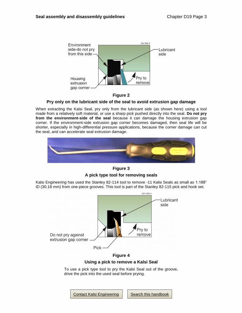
3. Extract the used Kalsi Seals. Avoid damaging the housing extrusion gap corner that
is located between the environment-side groove wall and the extrusion gap bore,
because corner damage can damage the Kalsi Seal (Figure 5). If seal extraction
requires prying, pry on the lubricant end of the seal with a soft tool to avoid
damaging the environment-side extrusion gap corner (See Figure 2). To avoid
groove damage, drive a pick or other tool into the seal, as an alternate way to
remove used Kalsi Seals (Figures 3 and 4).4
4 The extraction tool, and extraction method shown in U.S. Patents 1665988 and 5,836,099 may also be
useful in extracting rotary seals.
Seal assembly and disassembly guidelines Chapter D19 Page 3
Search this handbook Contact Kalsi Engineering
Figure 2
Pry only on the lubricant side of the seal to avoid extrusion gap damage
When extracting the Kalsi Seal, pry only from the lubricant side (as shown here) using a tool made from a relatively soft material, or use a sharp pick pushed directly into the seal. Do not pry from the environment-side of the seal because it can damage the housing extrusion gap corner. If the environment-side extrusion gap corner becomes damaged, then seal life will be shorter, especially in high-differential pressure applications, because the corner damage can cut the seal, and can accelerate seal extrusion damage.
Figure 3
A pick type tool for removing seals
Kalsi Engineering has used the Stanley 82-114 tool to remove -11 Kalsi Seals as small as 1.188” ID (30.18 mm) from one-piece grooves. This tool is part of the Stanley 82-115 pick and hook set.
Figure 4
Using a pick to remove a Kalsi Seal
To use a pick type tool to pry the Kalsi Seal out of the groove, drive the pick into the used seal before prying.
Seal assembly and disassembly guidelines Chapter D19 Page 4
Search this handbook Contact Kalsi Engineering
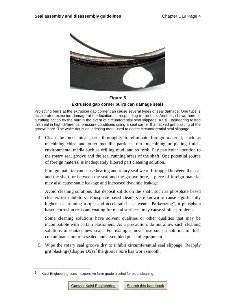
Figure 5
Extrusion gap corner burrs can damage seals
Projecting burrs at the extrusion gap corner can cause several types of seal damage. One type is accelerated extrusion damage at the location corresponding to the burr. Another, shown here, is a cutting action by the burr in the event of circumferential seal slippage. Kalsi Engineering tested this seal in high-differential pressure conditions using a seal carrier that lacked grit blasting of the groove bore. The white dot is an indexing mark used to detect circumferential seal slippage.
4. Clean the mechanical parts thoroughly to eliminate foreign material, such as
machining chips and other metallic particles, dirt, machining or plating fluids,
environmental media such as drilling mud, and so forth. Pay particular attention to
the rotary seal groove and the seal running areas of the shaft. One potential source
of foreign material is inadequately filtered part cleaning solution.
Foreign material can cause bearing and rotary seal wear. If trapped between the seal
and the shaft, or between the seal and the groove bore, a piece of foreign material
may also cause static leakage and increased dynamic leakage.
Avoid cleaning solutions that deposit solids on the shaft, such as phosphate based
cleaner/rust inhibitors5. Phosphate based cleaners are known to cause significantly
higher seal running torque and accelerated seal wear. “Parkerizing”, a phosphate
based corrosion resistant coating for metal surfaces, may cause similar problems.
Some cleaning solutions have solvent qualities or other qualities that may be
incompatible with certain elastomers. As a precaution, do not allow such cleaning
solutions to contact new seals. For example, never use such a solution to flush
contaminants out of a sealed and assembled piece of equipment.
5. Wipe the rotary seal groove dry to inhibit circumferential seal slippage. Reapply
grit blasting (Chapter D5) if the groove bore has worn smooth.
5 Kalsi Engineering uses inexpensive farm-grade alcohol for parts cleaning.

Seal assembly and disassembly guidelines Chapter D19 Page 5
Search this handbook Contact Kalsi Engineering
6. Inspect the installation paths and seal running areas of the shaft, looking for wear,
corrosion, and other damage that could adversely affect the Kalsi Seals. Polish,
hone, strip and recoat, or replace hard coatings as necessary, to restore the
recommended surface finish (Chapter D2). If recoating is necessary, then inspect
both the new coating and the installation chamfer prior to use of the refurbished
part. Improperly done, recoating can leave sharp features on the installation
chamfer; removing these before use is imperative (Figure 6).
Figure 6
Inspect the corner of the installation chamfer after tungsten carbide recoating of the shaft, to avoid sharp corners that could twist or damage the seal.
7. Inspect the seal housing for defects that could harm the rotary seal during
operation, and repair or replace components as necessary. Examples of such
defects are:
• Damaged extrusion gap corners, such as nicks, burrs, displaced metal
(Figure 7), or excessively large radii6,
• Seal groove worn out of tolerance from circumferential seal slippage,
• Roughening on the inner portion of the environment-side groove wall (Figure
9) which can detrimentally anchor seal material and increase third-body
abrasive wear of the seal,
• An extrusion gap bore that has worn oversize, and
• A journal bearing that has worn oversize, particularly if it permits metal-to-
metal contact between the shaft and the extrusion gap bore, or can cause
inadequate radial seal compression.
6 An excessively large extrusion gap corner radius can occur if the corner becomes damaged (i.e., nicks
& burrs), and someone attempts to sand down the damage with abrasive paper.
GA487.12
Correct installation chamferafter tungsten carbide recoating
Incorrect installation chamferafter tungsten carbide recoating(sharp corner must be removedbefore use to avoid seal damage)
Seal assembly and disassembly guidelines Chapter D19 Page 6
Search this handbook Contact Kalsi Engineering
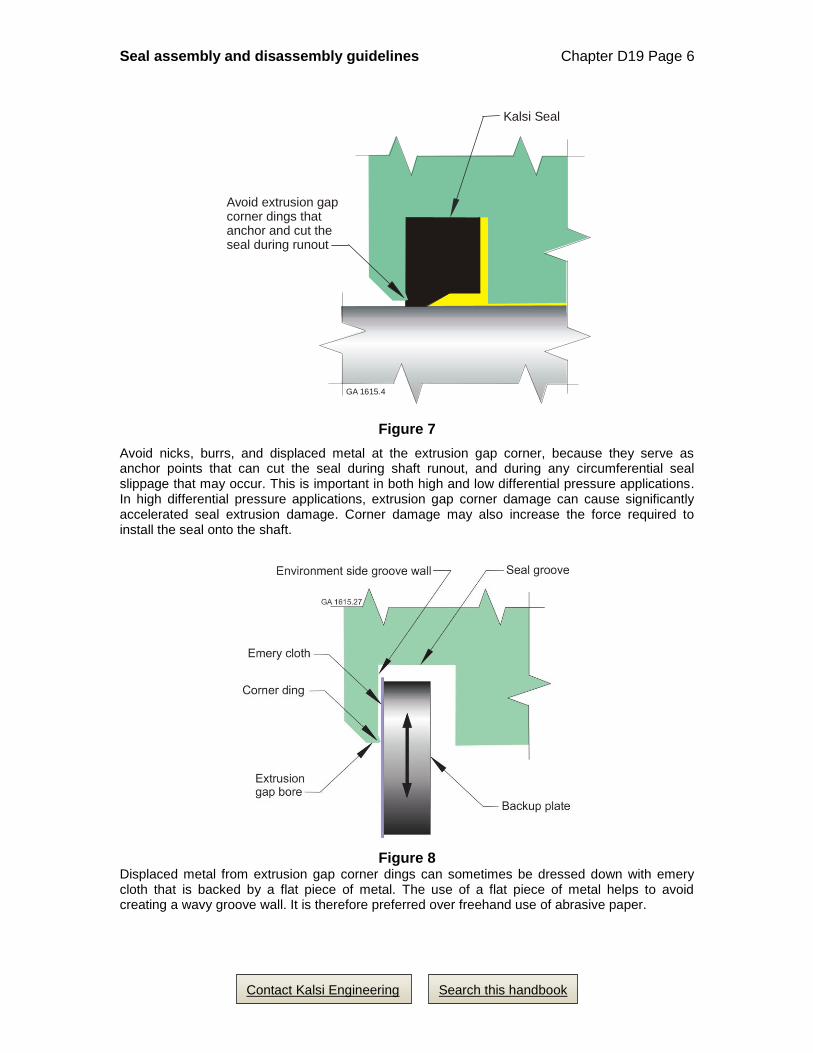
Figure 7
Avoid nicks, burrs, and displaced metal at the extrusion gap corner, because they serve as anchor points that can cut the seal during shaft runout, and during any circumferential seal slippage that may occur. This is important in both high and low differential pressure applications. In high differential pressure applications, extrusion gap corner damage can cause significantly accelerated seal extrusion damage. Corner damage may also increase the force required to install the seal onto the shaft.
Figure 8 Displaced metal from extrusion gap corner dings can sometimes be dressed down with emery cloth that is backed by a flat piece of metal. The use of a flat piece of metal helps to avoid creating a wavy groove wall. It is therefore preferred over freehand use of abrasive paper.
Kalsi Seal
Avoid extrusion gapcorner dings that anchor and cut theseal during runout
GA 1615.4

Seal assembly and disassembly guidelines Chapter D19 Page 7
Search this handbook Contact Kalsi Engineering
Figure 9 This photo is an enlargement of the flat environment-side seal groove wall and the adjacent radially inwardly facing extrusion gap bore of a seal carrier made from UNS S17400. The seal carrier was used in tests of Kalsi Seals that were operating on a shaft with ~0.010” runout FIM in the presence of a drilling fluid environment. Note the radially oriented wear marks on the groove wall near the intersection with the extrusion gap bore. As this type of wear increases, the abrasion resistance of the seal decreases.
4. Kalsi Seal assembly
1. Use appropriate safety practices, such as wearing goggles and rubber gloves for
protection from solvents, and wearing steel-toed shoes for protection from falling
articles.
2. Ensure that any newly manufactured hardware is free of manufacturing debris, such
as metal chips, dried cutting fluid, dried plating fluid, etc.
3. Degrease the seal groove with an evaporative-type residue-free solvent degreaser
(Figure 10).

Seal assembly and disassembly guidelines Chapter D19 Page 8
Search this handbook Contact Kalsi Engineering
Figure 10
Degrease the seal groove
Beware that immersion in a typical parts cleaner solution usually leaves a seal carrier slightly oily, because the solution becomes contaminated with lubricant over time. To inhibit circumferential seal slippage, degrease the seal groove using an evaporative-type residue-free solvent degreaser. Allow the degreaser to evaporate before inserting the Kalsi Seal.
4. Observe proper seal orientation, and insert the seal into the groove. The end of the
seal marked “lubricant side” must face a lubricant (see Figure 11). If both sides of
the seal will face lubricant, then turn the “lubricant side” to face the higher-pressure
region. To inhibit circumferential seal slippage, do not lubricate the groove, and do
not lubricate the seal prior to installing the seal into the groove (Figure 13).
The unfolded insertion technique shown in Figure 14 works well with larger
diameter seals that are constructed entirely from elastomer. The folded seal
insertion technique shown in Figure 15 works with elastomeric seals as small as the
1.375” ID -11 ACS seal, and may work with even smaller sizes as well. For
convenience, a custom insertion tool (Figure 15) can hold small diameter seals in
the folded condition. Small diameter seals (and seals that incorporate metal springs,
fabric reinforcement, or plastic) may require a removable groove wall, to allow
insertion of the seal into the groove. For an example of a removable groove wall,
see Figure 16. For additional information about small diameter seals and removable
groove walls, see Chapter D6.

Seal assembly and disassembly guidelines Chapter D19 Page 9
Search this handbook Contact Kalsi Engineering
Figure 11
Kalsi Seal orientation is critical because the wavy hydrodynamic edge must face a lubricant. On most seals, the lubricant side is marked “lubricant side”. A Wide Footprint Kalsi Seal, shown here, is suitable for either direction of rotation. On certain types of seals, such as High Film Seals, the lip geometry is directional, and must match to the direction of shaft rotation.
Figure 12
Do not lubricate the outside diameter of the Kalsi Seal or the seal groove!
Neither the Kalsi Seal nor its seal groove should be lubricated prior to inserting the seal into the groove. Instead, the seal groove should be thoroughly degreased with an evaporative-type residue-free solvent degreaser prior to inserting the seal, and both the seal and the groove should be dry at the time of seal insertion.
Seal assembly and disassembly guidelines Chapter D19 Page 10
Search this handbook Contact Kalsi Engineering
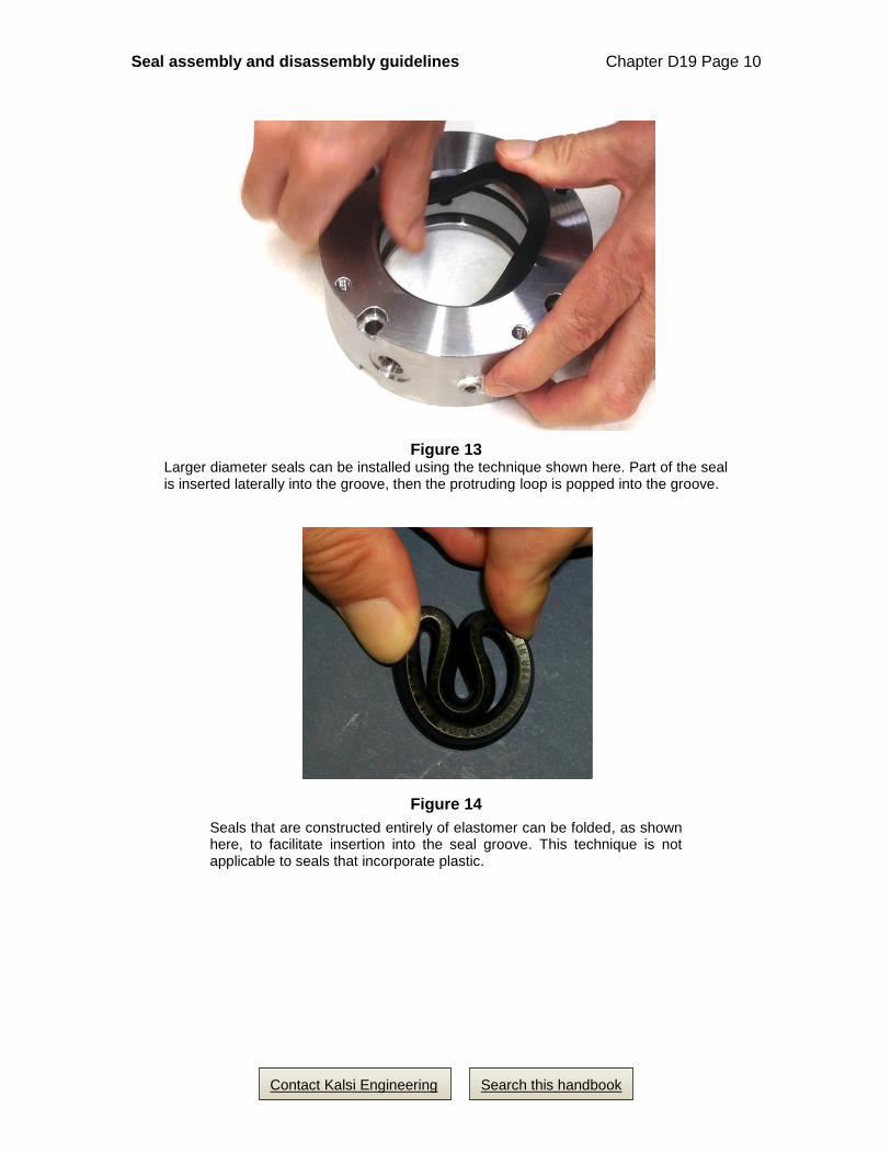
Figure 13 Larger diameter seals can be installed using the technique shown here. Part of the seal is inserted laterally into the groove, then the protruding loop is popped into the groove.
Figure 14
Seals that are constructed entirely of elastomer can be folded, as shown here, to facilitate insertion into the seal groove. This technique is not applicable to seals that incorporate plastic.

Seal assembly and disassembly guidelines Chapter D19 Page 11
Search this handbook Contact Kalsi Engineering
Figure 15
Custom built tools can facilitate insertion of small diameter elastomeric seals
Figure 16
Some seals require a removable groove wall
Some seals cannot be installed without the use of a removable groove wall. Examples include small diameter elastomeric seals, and many seals that include plastic, fabric reinforcement, and/or metal springs in their construction.

Seal assembly and disassembly guidelines Chapter D19 Page 12
Search this handbook Contact Kalsi Engineering
5. Lubricate the seal installation path on the shaft, including the installation chamfer
and the sealing surface. The same lubricant used in the machinery can serve this
purpose. If the machinery uses a low viscosity lubricant, then using a higher
viscosity installation lubricant (such as Mobil SHC-1000) can lower installation
force and rotary seal breakout torque. Lubricant should be compatible with the seal
material, the process fluid and the temperature range of the application, and with
any lubricant filtration and circulation equipment employed.
Figure 17
Lubricate the seal installation path
The seal installation path includes any shaft surface the seal touches during installation, including the installation chamfer and the sealing surface. Lubricate the seal installation path prior to installing the seal onto the shaft.

Seal assembly and disassembly guidelines Chapter D19 Page 13
Search this handbook Contact Kalsi Engineering
6. After installing the seal into the groove of the seal carrier, lightly lubricate the
inside diameter of the seal to reduce installation force, to help prevent installation
damage, and to reduce startup torque. Do not slather lubricant all over the bore of
the seal carrier (Figure 18); just apply the lubricant to the inside diameter of the
seal. Prior to the seal being compressed between the groove and the shaft, excess
lubricant within the seal carrier may inadvertently result in lubricant seeping
between the static lip of the seal and the mating bore of the seal groove.
Figure 18
Do not slather the seal carrier with lubricant
It is not beneficial to slather the bore of the seal carrier with lubricant — and in some cases, it may be detrimental, because it may result in inadvertent lubrication of the static lip of the rotary seal. After the dry, unlubricated seal is installed in the dry, unlubricated groove of the seal carrier, apply a light coating of lubricant to the inner-most surface of the seal. Do not apply lubricant to the inner surfaces of the seal carrier, except in cases were a bore of the seal carrier serves as a journal bearing.

Seal assembly and disassembly guidelines Chapter D19 Page 14
Search this handbook Contact Kalsi Engineering
7. Align the shaft carefully to ensure that initial seal contact takes place on the shaft
chamfer, and then insert the shaft. Improper insertion can damage or roll the seal
(see Figure 19). Large diameter, solid cross section seals require considerable force
to install, and typically require mechanical assistance, such as a hydraulic press or
simple thread-driven press. If a seal requires an unusually large amount of force to
install, then check to make sure that the groove width or diameter isn’t too small,
and check for the improper installation chamfer conditions shown in Figures 6 and
19. For additional information on the seal installation path, see Chapter D3.
Figure 19 To avoid seal damage, be sure the seal makes initial contact with the installation chamfer, and not with the shaft shoulder.
8. Add lubricant to the equipment in a manner that eliminates air so the hydrodynamic
edge of the Kalsi Seals is next to lubricant, rather than air. Beware of the bell jar
effect (Figure 20). See Section 5 of this chapter for a variety of methods to fill
equipment with lubricant while eliminating air.
9. Do not overfill the lubricant reservoir. The reservoir must allow room for lubricant
thermal expansion. Failure to allow room for lubricant thermal expansion can cause
seal and hardware damage.
10. If the Kalsi Seals will encounter an abrasive process fluid, then seat the seals
against the environment-side groove wall by temporarily applying approximately
100 psi (690 kPa) lubricant pressure.

Seal assembly and disassembly guidelines Chapter D19 Page 15
Search this handbook Contact Kalsi Engineering
Figure 20
Beware of the ‘bell jar effect’
In this simple experiment, the trapped air within a submerged bell jar prevents the interior of the bell jar from filling up with water. Likewise, air within an assembly can prevent lubricant from reaching the Kalsi Seal, especially in vertical shaft arrangements.
5. Lubricant filling methods
Filling horizontal shaft applications
In horizontal shaft applications, fill the lubricant through a port on the bottom side of
the housing, and allow the air to escape at a port on the top side, as shown in Figure 21.
Kalsi Engineering uses this method to fill the majority of its rotary seal test fixtures. A
small pocket of air is present at the top side of the seal grooves due to bell jar effect, but
it does no harm as long as the assembly remains horizontal during operation.
Depending on the construction of the lubricant reservoir, either the lubricant
reservoir, a lubricant pump, or an air over oil-based lubricant transfer tank (Figure 22)
can be used to fill the seal housing.

Seal assembly and disassembly guidelines Chapter D19 Page 16
Search this handbook Contact Kalsi Engineering
Figure 21
In horizontal shaft applications, one can eliminate air by performing the oil fill through the bottom port of the seal housing. As the oil enters and rises, it displaces the air, which escapes through the temporarily open top port.

Seal assembly and disassembly guidelines Chapter D19 Page 17
Search this handbook Contact Kalsi Engineering
Figure 22
A simple air over oil-based lubricant transfer tank
We at Kalsi Engineering use air over oil tanks like this to fill the lubricant reservoirs and seal housings of our horizontal shaft-type rotary seal test fixtures. Shop air pressure, introduced through the quick connect coupling at the top of the tank, forces the lubricant through the valve at the bottom of the tank, and into the test fixture. The tank is disconnected from the test fixture prior to use, to isolate the tank from the lubricant pressure of the test fixture.

Seal assembly and disassembly guidelines Chapter D19 Page 18
Search this handbook Contact Kalsi Engineering
Vacuum filling of the seal lubricant
Vacuum filling is desirable for vertical shaft applications that run at relatively low
lubricant pressure, because it helps to prevent the formation of an air pocket below the
upper rotary seal. If an air pocket is large enough, it can cause lubricant starvation of the
upper seal. Vacuum filling also is desirable when minimizing lubricant pressure lag is
important; it takes time for a piston or diaphragm to move and collapse entrained air and
air pockets.
Evacuate the lubricant region of the equipment using a vacuum pump7. Introduce
the lubricant into the evacuated area, then pressurize the lubricant to force a complete fill,
valving off the pressure for a short period to verify sealing integrity. Beware that drawing
oil into your vacuum pump may damage it; Figure 23 shows a way to protect a vacuum
pump from oil entry.
One risk of vacuum filling is that the vacuum can pull streams of air into the
lubricant if a filling system leak occurs. To avoid this situation, periodically check the
entire filling system for leaks; also check the equipment being filled, to detect leaks prior
to introducing the lubricant. One way to check for leaks is to draw a vacuum on the
system, then monitor the vacuum gauge for a few minutes to see if the vacuum pressure
changes. Use clear tubing on vacuum filling systems to facilitate identification and
elimination any entrained air problems. If opting not to use vacuum filling techniques,
then purge any hoses that are a part of the rotary equipment to eliminate air from the
hoses.
Lubricant typically contains a significant amount of entrained air. To prove this to
yourself, put lubricant in a clear vessel and pull a vacuum on it, and watch the bubbles
come streaming out. In vertical shaft equipment, the entrained air may create an air
pocket that causes lubricant starvation at the upper rotary seal. In such applications, it is
desirable to degas the lubricant, and then evacuate the equipment with a vacuum pump
before filling with lubricant. Figure 24 is a schematic representation of a lubricant
degasser.
7 Commercial lubricant filling systems are available that have heaters to lower the viscosity of high
viscosity lubricants, for ease of filling.
Seal assembly and disassembly guidelines Chapter D19 Page 19
Search this handbook Contact Kalsi Engineering
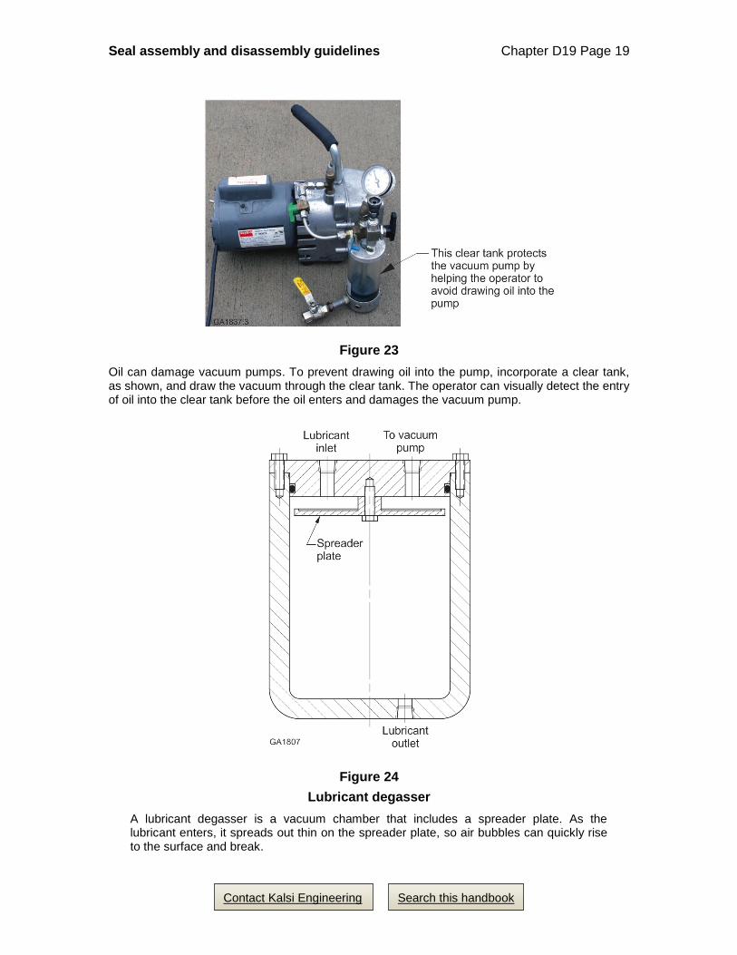
Figure 23
Oil can damage vacuum pumps. To prevent drawing oil into the pump, incorporate a clear tank, as shown, and draw the vacuum through the clear tank. The operator can visually detect the entry of oil into the clear tank before the oil enters and damages the vacuum pump.
Figure 24
Lubricant degasser
A lubricant degasser is a vacuum chamber that includes a spreader plate. As the lubricant enters, it spreads out thin on the spreader plate, so air bubbles can quickly rise to the surface and break.

Seal assembly and disassembly guidelines Chapter D19 Page 20
Search this handbook Contact Kalsi Engineering
Exploiting gravity to achieve a good fill in vertical shaft equipment
Figure 25 shows a simple method for filling swivel type devices that have a journal
bearing relationship between the seal carrier and the rotary shaft. It also works with
certain other types of rotary equipment. Orient the shaft vertically, and then push the
housing down over the top of the shaft until the lower rotary seal engages the shaft. Pour
some lubricant into the housing to create a pool of lubricant, then install the housing the
rest of the way onto the shaft. (If using hollow shafts, then you may need to cap or plug
the shaft so that the housing can hold a suitable volume of lubricant.) With simple
housings that contain few, if any, internal components, this method eliminates nearly all
the air by effectively immersing the inside of the housing in lubricant throughout the
installation process. To ensure a complete fill, be sure that the initial pool of lubricant is
enough to overflow the housing during installation. Perform the installation in a tub to
capture the lubricant overflow.
Figure 25
One method of eliminating air from the lubricant is to use the seal carrier housing as a reservoir that floods all housing-to-shaft clearances with lubricant during housing installation. This provides the same effect as submerging the equipment in a tank of lubricant during assembly.
GA1659.1
Solid or temporarilycapped hollow shaftAs the housing slowly
slides down the shaft,lubricant completelyfills the space be-tween the shaft and the housing
Kalsi Seals
Quick disconnects
Seal CarrierHousing

Seal assembly and disassembly guidelines Chapter D19 Page 21
Search this handbook Contact Kalsi Engineering
6. Shop training classes
Kalsi Seal shop training classes (Figure 26) are available at our location or yours, or
via Internet conferencing. The training provides a general introduction to the Kalsi Seal
with a review of items to look for during disassembly of equipment, and a review of good
equipment assembly practices. This class is kept to about 45 minutes to limit its impact
on the customer’s production.
Figure 26
Rotary seal training classes
Seal related shop and engineering training classes are available in person, or via Internet conferencing. Kalsi Engineering can tailor the classes for relevance to your specific rotary sealing application.