Sea modelling and rendering - OKTAL-SE · 2017-05-16 · Sea modelling and rendering Jean LATGER,...
15
Sea modelling and rendering Jean LATGER, Thierry CATHALA Oktal Synthetic Environment, France 1. INTRODUCTION More and more defence and civil applications require simulation of marine synthetic environment. Currently, the «Future Anti-Surface-Guided-Weapon» (FASGW) or «anti-navire léger» (ANL) missile needs this kind of modelling. This paper presents a set of technical enhancement of the SE-Workbench that aim at better representing the sea profile and the interaction with targets. The operational scenario variability is a key criterion: the generic geographical area (e.g. Persian Gulf, coast of Somalia, …), the type of situation (e.g. peace keeping, peace enforcement, anti-piracy, drug interdiction, …), the objectives (political, strategic, or military objectives), the description of the mission(s) (e.g. anti- piracy) and operation(s) (e.g. surveillance and reconnaissance, escort, convoying) to achieve the objectives, the type of environment (Weather, Time of day, Geography [coastlines, islands, hills/mountains]). The paper insists on several points such as the dual rendering using either ray tracing [and the GP GPU optimization] or rasterization [and GPU shaders optimization], the modelling of sea-surface based on hypertextures and shaders, the wakes modelling, the buoyancy models for targets, the interaction of coast and littoral, the dielectric infrared modelling of water material. 2. SE-WORKBENCH-IR TOOL 2.1 Overall presentation of the SE-Workbench The SE-WORKBENCH, also called CHORALE, is a multi-sensor battlefield modeling workbench mainly used by French DGA, German BWB, South Korea MnD, Singapore DSTA and Swedish FOI in order to achieve the synthesis of 3D scene observed by a sensor, this in two steps: • The physical characterization of the 3D scene behavior • The Computation of the physical signal received by a sensor. The SE-WORKBENCH is entirely based on software products developed by OKTAL-SE and realize the multi-spectral unification of optronics, electromagnetism and more recently GNSS, using a common kernel & physical extensions affectation both aimed at a unique 3D scene and a common technology. The SE-WORKBENCH is a winning initiative for sharing R&D efforts and federating a user group community that intends to exchange experience and knowledge. The first development was in 1994 and has been strongly boosted by the French SCALP missile program and the qualification of the IR tracking system. At the beginning, the SE-WORKBENCH was focused on the IR domain. In 2001, an electromagnetic version of the workshop was initiated, with the help of ONERA French research center, mainly focused on millimeter waves and wide scenes, typically for SAR applications. A new GNSS version for satellite application has started in 2009. The control of the SE-WORBENCH validity domain is based on both a theoretical validation approach (development of physical models, general modeling and simulation knowledge, elementary tests and validity assessment) and a validation process based on comparisons with experiments (SCALP/EG missile [FR], AASM missile [FR]). 2.2 The SE-WORKBENCH-IR architecture The SE-WORKBENCH-IR is made of different components, as described hereafter, corresponding to the successive steps of a IR sensor simulation that are the modeling, the scenario edition, the rendering without the sensor effects and finally the sensor transfer function simulation. Furthermore, the user can do software integration in order to control the generated scenario execution from a remote or custom application. This can be achieved with the help of the SE-
Transcript of Sea modelling and rendering - OKTAL-SE · 2017-05-16 · Sea modelling and rendering Jean LATGER,...

Sea modelling and rendering
Jean LATGER, Thierry CATHALA
Oktal Synthetic Environment, France
1. INTRODUCTION
More and more defence and civil applications require simulation of marine synthetic environment. Currently, the «Future Anti-Surface-Guided-Weapon» (FASGW) or «anti-navire léger» (ANL) missile needs this kind of modelling. This paper presents a set of technical enhancement of the SE-Workbench that aim at better representing the sea profile and the interaction with targets. The operational scenario variability is a key criterion: the generic geographical area (e.g. Persian Gulf, coast of Somalia, …), the type of situation (e.g. peace keeping, peace enforcement, anti-piracy, drug interdiction, …), the objectives (political, strategic, or military objectives), the description of the mission(s) (e.g. anti-piracy) and operation(s) (e.g. surveillance and reconnaissance, escort, convoying) to achieve the objectives, the type of environment (Weather, Time of day, Geography [coastlines, islands, hills/mountains]).
The paper insists on several points such as the dual rendering using either ray tracing [and the GP GPU optimization] or rasterization [and GPU shaders optimization], the modelling of sea-surface based on hypertextures and shaders, the wakes modelling, the buoyancy models for targets, the interaction of coast and littoral, the dielectric infrared modelling of water material.
2. SE-WORKBENCH-IR TOOL
2.1 Overall presentation of the SE-Workbench
The SE-WORKBENCH, also called CHORALE, is a multi-sensor battlefield modeling workbench mainly used by French DGA, German BWB, South Korea MnD, Singapore DSTA and Swedish FOI in order to achieve the synthesis of 3D scene observed by a sensor, this in two steps:
• The physical characterization of the 3D scene behavior
• The Computation of the physical signal received by a sensor.
The SE-WORKBENCH is entirely based on software products developed by OKTAL-SE and realize the multi-spectral unification of optronics, electromagnetism and more recently GNSS, using a common kernel & physical extensions affectation both aimed at a unique 3D scene and a common technology. The SE-WORKBENCH is a winning initiative for sharing R&D efforts and federating a user group community that intends to exchange experience and knowledge. The first development was in 1994 and has been strongly boosted by the French SCALP missile program and the qualification of the IR tracking system. At the beginning, the SE-WORKBENCH was focused on the IR domain. In 2001, an electromagnetic version of the workshop was initiated, with the help of ONERA French research center, mainly focused on millimeter waves and wide scenes, typically for SAR applications. A new GNSS version for satellite application has started in 2009. The control of the SE-WORBENCH validity domain is based on both a theoretical validation approach (development of physical models, general modeling and simulation knowledge, elementary tests and validity assessment) and a validation process based on comparisons with experiments (SCALP/EG missile [FR], AASM missile [FR]). 2.2 The SE-WORKBENCH-IR architecture
The SE-WORKBENCH-IR is made of different components, as described hereafter, corresponding to the successive steps of a IR sensor simulation that are the modeling, the scenario edition, the rendering without the sensor effects and finally the sensor transfer function simulation. Furthermore, the user can do software integration in order to control the generated scenario execution from a remote or custom application. This can be achieved with the help of the SE-

TOOLKIT consisting of a set of dedicated libraries and application programming interfaces (API) to help the complex application design and integration.
Synthetic environment modeling
Scenario editing and preview, software integration services
Real time exploitation
Non Real Time exploitation
Sensor effects modeling and integration
Synthetic environment modeling
Scenario editing and preview, software integration services
Real time exploitation
Non Real Time exploitation
Sensor effects modeling and integration
Figure 1: The SE-WORKBENCH-IR components.
2.3 Non real time rendering based on SE-RAY-IR
SE-RAY is the ray tracing kernel developed by OKTAL-SE which enables to compute high realism images in several spectral domains. SE-RAY-IR is dedicated to the rendering of synthetic environments in the IR domain and is based on SE-RAY ray tracing kernel. The great originality of SE-RAY comes from its model based on physics. SE-RAY uses elementary pyramids, defined by four adjacent rays (one basic pixel), which allows one to compute elementary surfaces and solid angles.
Besides SE-RAY-IR takes into account the wavelength sampling. Actually SE-RAY-IR works wavelength by wavelength. Time consumption is very optimized using SE-RAY. Actually performances are nearly independent on scene complexity. To do this SE-RAY uses a spatial subdivision method that enables to get a perfect knowledge of the scene topology before computing the first image. The scene space is decomposed in a hierarchy of volume elements (voxels) and then turned into a recursive space of voxels that improves efficiently the intersection computations. The solution to improve image quality mainly consists in over sampling by tracing more rays. The method adopted for SE-RAY-IR is the adaptative one. The most important antialiasing criteria are the following: number of different polygons in the pixel, number of different materials, normal vector variation within the pixel. Based on generalization of texture definition to any physical data, SE-RAY-IR can simulate the variation of specular reflectivity with the observation angles.
polygon j+1
n j+1
n
polygon j θ j+1
θ j+1 θ j θ
G j
G j+1 j
n j+2
G j+2
θ j+2
θ j+2
j
polygon j+2
j+2 S
j+1 S
j S
Figure 2: Management of ray tubes in SE-RAY-IR
Concerning the physical IR model, SE-RAY-IR can take the following contributions into account:
• The thermal emission
• Diffuse and specular reflections

• Direct Sun lighting: Direct sun or moon lighting takes into account the atmospheric attenuation and diffusion between the astral source and any point in the 3D scene. An external data file (typically based on LOWTRAN or MODTRAN) contains attenuation and diffusion values for discrete values of the wavelength and of the altitude.
• Diffuse Sun lighting and sky/ground illumination: Sky and ground are considered as a global entity providing energy in any space direction. When loading the database, the canopy is tessellated in discrete solid angles defined using elevation and azimuth angles.
• Self emission of the atmosphere: An external data file (typically based on MODTRAN or MATISSE) contains atmospheric radiance data for discrete values of wavelength, altitude, elevation, azimuth and range. For each ray, both primary, secondary or lighting ray, the best value of atmospheric radiance is determined using linear interpolation.
• Atmospheric attenuation: An external data file (typically based on MODTRAN or MATISSE) contains atmospheric attenuation for discrete values of wavelength, altitude, elevation and range. For each ray, both primary, secondary or lighting ray, the best value of atmospheric attenuation is determined using linear interpolation
• Sky, horizon and cloud cover: Sky and horizon are pure analytic models.
Beyond this classical forward ray-tracing, SE-RAY-IR uses SE-RAY-PHOTON-MAP module in order to take advantage of photon maps to pre-compute the scene global illumination, in a first pass, and then to trace rays from the observer to the scene, in a second pass.
light
ϕ1ϕ1
diffusion
diffusion
nn
reflexion
absorption
3D scenesensor
absorption
diffusion
ϕ3ϕ3
ϕ2ϕ2
Figure 3: Path 1 & Path 2 of SE-RAY-IR
In the first pass, a ray tracing is made from each source, through the atmosphere. A ray is either absorbed, either diffused or scattered in a direction given by the local phase function and can be also reflected by the scene geometry. After this first pass, lots of “photons” are stored on the scene surfaces as local irradiances. In the second pass, rays are traced from the observer onto the geometry, and the radiance pixel computation takes into account the local interpolated irradiances thanks to the BRDF.
2.4 Real time rendering based on SE-FAST-IR package
The SE-FAST-IR package is made of a major product (SE-FAST-IR) and additional modules depending on the considered application.
With the help of some pre-calculation steps, real time images are computed with the SE-FAST-IR solution. It is dedicated to the computation of image sequences for near infrared sensors (light intensifying) and thermal infrared systems with short, medium or long waves (SWIR, MWIR, LWIR). The products make use of the results of the SE-CLASSIFICATION tool, the SE-PHYSICAL-MODELER modeler and the SE-ATMOSPHERE atmospheric files computation product. The thermal pre-calculations are based on SE-THERMAL code.
The previous version of SE-FAST-IR was based on a pre computation of the whole 3D scene with specific radiance texture adapted to a given waveband for a given spectral response. The real time process only consisted in using
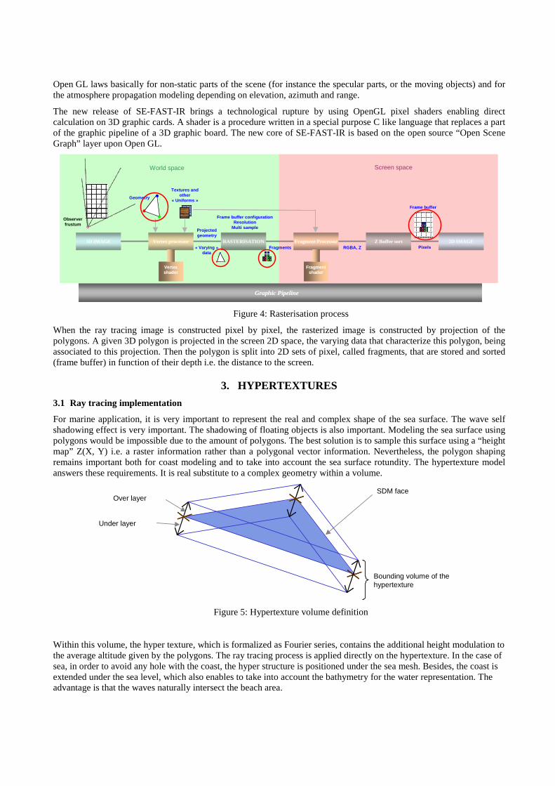
Open GL laws basically for non-static parts of the scene (for instance the specular parts, or the moving objects) and for the atmosphere propagation modeling depending on elevation, azimuth and range.
The new release of SE-FAST-IR brings a technological rupture by using OpenGL pixel shaders enabling direct calculation on 3D graphic cards. A shader is a procedure written in a special purpose C like language that replaces a part of the graphic pipeline of a 3D graphic board. The new core of SE-FAST-IR is based on the open source “Open Scene Graph” layer upon Open GL.
World space Screen space
Observer frustum
Textures and other
« Uniforms »
3D IMAGE Vertex processor RASTERISATION Fragment Processor 2D IMAGE
Graphic Pipeline
Vertex shader
Fragment shader
Geometry
Projected geometry
« Varying » data
Fragments RGBA, ZZ Buffer sort
Pixels
Frame buffer
Frame buffer configuration Resolution
Multi sample
World space Screen space
Observer frustum
Textures and other
« Uniforms »
3D IMAGE Vertex processor RASTERISATION Fragment Processor 2D IMAGE
Graphic Pipeline
Vertex shader Vertex shader Vertex shader
Fragment shader
Fragment shader
Fragment shader
Geometry
Projected geometry
« Varying » data
Fragments RGBA, ZZ Buffer sort
Pixels
Frame buffer
Frame buffer configuration Resolution
Multi sample
Figure 4: Rasterisation process
When the ray tracing image is constructed pixel by pixel, the rasterized image is constructed by projection of the polygons. A given 3D polygon is projected in the screen 2D space, the varying data that characterize this polygon, being associated to this projection. Then the polygon is split into 2D sets of pixel, called fragments, that are stored and sorted (frame buffer) in function of their depth i.e. the distance to the screen.
3. HYPERTEXTURES
3.1 Ray tracing implementation
For marine application, it is very important to represent the real and complex shape of the sea surface. The wave self shadowing effect is very important. The shadowing of floating objects is also important. Modeling the sea surface using polygons would be impossible due to the amount of polygons. The best solution is to sample this surface using a “height map” Z(X, Y) i.e. a raster information rather than a polygonal vector information. Nevertheless, the polygon shaping remains important both for coast modeling and to take into account the sea surface rotundity. The hypertexture model answers these requirements. It is real substitute to a complex geometry within a volume.
Bounding volume of the hypertexture
SDM faceOver layer
Under layer
Figure 5: Hypertexture volume definition
Within this volume, the hyper texture, which is formalized as Fourier series, contains the additional height modulation to the average altitude given by the polygons. The ray tracing process is applied directly on the hypertexture. In the case of sea, in order to avoid any hole with the coast, the hyper structure is positioned under the sea mesh. Besides, the coast is extended under the sea level, which also enables to take into account the bathymetry for the water representation. The advantage is that the waves naturally intersect the beach area.
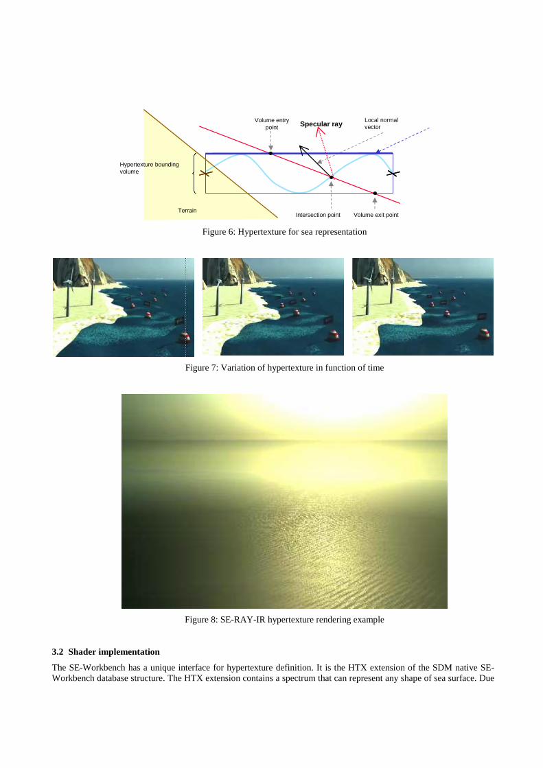
Volume entry point
Volume exit point
Local normal vector
Intersection point
Specular ray
Hypertexture bounding volume
Terrain
Figure 6: Hypertexture for sea representation
Figure 7: Variation of hypertexture in function of time
Figure 8: SE-RAY-IR hypertexture rendering example
3.2 Shader implementation
The SE-Workbench has a unique interface for hypertexture definition. It is the HTX extension of the SDM native SE-Workbench database structure. The HTX extension contains a spectrum that can represent any shape of sea surface. Due

to time constraint for real time application, a special interpretation of hypertextures is made in SE-FAST-IR that gives an equivalent to the ray tracing treatment. The RT rendering is nearly equivalent to the NRT management. The main limitations are currently the following:
• Less number of frequencies in the Fourier decomposition (limited by the shader memory size) • Spectral computation much less accurate (limited number of wavelength within the sensor band) • Worse quality of antialiasing (Cf. hereafter) A special pixel shader has been written, that implements an algorithm inherited from “parallax mapping” and “relief mapping”, classical graphical techniques in the video game domain.
Figure 9: RT treatment of height maps
The T(u, v) texture that classically contains a color information, here contains a height information, actually a relative height to the polygon mean surface, that is positioned in the polygon plan thanks to the texture coordinates or the texture matrix. The u,v texture coordinate of the “height map” is modified in function of the viewing angle as shown in figure 9, taking into account the viewing angle. The drawback of this basic technique is that no occlusion nor self shadowing effects can be rendered. OKTAL-SE has improved this technique, using a “ray marching” algorithm on GPU that finds the real intersection point with the height map, which gives occlusion effect and shadowing effects. The only limitation of the basic rendering is the aliasing intrinsic to this method.
Besides, the process enables to take into account specular reflection effects on sea surface:
Figure 10: RT SE-FAST images, with various water states

4. SEA MODEL
4.1 Introduction
The basis for deep-water wave spectrum models is the energy balance equation:
∑=∇+∂∂ →→
iSEgt
E c .
where t denotes time, E is the two-dimensional wave spectrum depending on frequency f and direction θ, cg is the group velocity, and Si represents the source and sink terms. A source term transfers energy into the system, whereas a sink term takes energy out of the system. In theory, the sum of all source and sink terms is zero.
In first generation wave spectrum models, the source and sink terms are modeled by two decoupled, linear processes. A famous model is the Pierson Moskowitz model.
In second generation wave spectrum models, the nonlinear wave-wave interaction term is parameterized to limit the required computational load. A famous model is the Jonswap model.
The limitations to the spectral shape are no longer needed in third generation wave spectrum models. In these models, the previous energy balance equation is solved explicitly.
For the SE-Workbench marine toolkit, an open source third generation wave spectrum model has been reused.
4.2 Bathymetry
To compute the E two-dimensional wave spectrum, bathymetric data are required. This terrain data under sea are easily managed in SE-AGETIM modeling tool. These raw regular gridded data are adaptively meshed in order to give more accuracy in the coast vicinity:
-30.00-20.00
-10.000.0010.00
-30.00-20.00
-10.000.0010.00
Figure 11: Optimization of bathymetry data
4.3 Third generation model implementation
We suppose that each frequency has its own propagation vector: sin(wt+k.x) considering a cg group velocity that gives a k propagation vector. So we can forget the time dimension and focus on the E two-dimensional wave spectrum

depending on frequency f and azimuth direction θ. The third generation model gives this spectrum for a given position in the 3D marine scene.
5 45
85 125 16
5 205 24
5 285 32
5
0.05
21
0.08
39
0.13
51
0.21
76
0.35
05
0.56
45
0.90
91
0.000
0.001
0.002
0.003
0.004
0.005
0.006
0.007
0.008
0.009
0.010
PERIOD
Figure 12: Wave spectrum function of f and θ
This polar spectrum must be transformed in a Cartesian frame:
Figure 13: Wave spectrum function of fx and fy
Actually the transformed spectrum is a local spectrum (in the vicinity of the Xi, Yi origin of each computation). Then, using all these {EXi, Yi }, a global interpolation is made that gives the spectrum for any x, y position in the scene. Then the inverse Fourier transform gives the wave amplitude Z(x, y). Before that, to make the rendering more realistic without perturbing the physical validity, we multiply in Fourier domain by a White Noise since the WN Power Spectral Density is equal to 1(fx, fy)) and does not affect the sea model PSD.
fy
fx
E(fx,fy)

WN(x,y) x E(fx, fx)E(fx, fx)
Figure 14: WN spectral effects
Which gives the following architecture:
FT-1WN(x,y)
E(fx, fx)
z(x, y)
E(f,θ)
CartesianTo
Polarconvertion
WNgeneration
X
X
Propagationmodel z(x, y, t)z(x, y)
Figure 15: Global treatment
5. MARINE SPECIAL EFFECTS
Several basic mechanisms have been developed in order to render some very important effects, such as wakes that are very important for ship detection and identification.
5.1 Water droplets particle systems
The first mechanism is the particle systems. Particles systems are made of lots of elementary objects, that, in the marine context, characterize a unitary 3D foam volume (with its associated physical spectral data). The behavior - in space and time - of these particles is controlled either by the SE-SCENARIO scenario file, either by PYTHON scripts or C/C++ code thanks to the SE-Workbench associated toolkits.
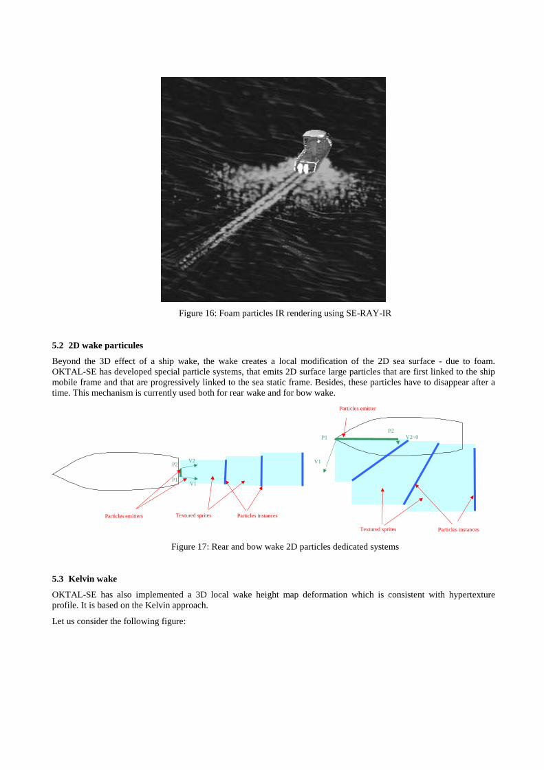
Figure 16: Foam particles IR rendering using SE-RAY-IR
5.2 2D wake particules
Beyond the 3D effect of a ship wake, the wake creates a local modification of the 2D sea surface - due to foam. OKTAL-SE has developed special particle systems, that emits 2D surface large particles that are first linked to the ship mobile frame and that are progressively linked to the sea static frame. Besides, these particles have to disappear after a time. This mechanism is currently used both for rear wake and for bow wake.
Textured sprites Particles instances Particles emitters
P1 V1
P2 V2
Textured sprites Particles instances
Particles emitter
P1
V1
P2 V2~0
Figure 17: Rear and bow wake 2D particles dedicated systems
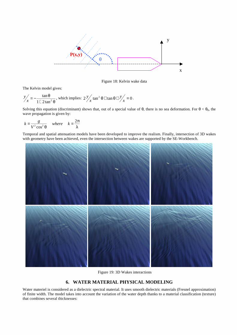
5.3 Kelvin wake
OKTAL-SE has also implemented a 3D local wake height map deformation which is consistent with hypertexture profile. It is based on the Kelvin approach.
Let us consider the following figure:
x
y
θ P(x,y)
Figure 18: Kelvin wake data
The Kelvin model gives:
θ+θ−=
2tan21
tanx
y , which implies: 0tantan2 2 =+θ+θ xy
xy .
Solving this equation (discriminant) shows that, out of a special value of θ, there is no sea deformation. For θ < θ0, the wave propagation is given by:
λπ=
θ= 2
cos22kwhere
V
gk
Temporal and spatial attenuation models have been developed to improve the realism. Finally, intersection of 3D wakes with geometry have been achieved, even the intersection between wakes are supported by the SE-Workbench.
Figure 19: 3D Wakes interactions
6. WATER MATERIAL PHYSICAL MODELING
Water materiel is considered as a dielectric spectral material. It uses smooth dielectric materials (Fresnel approximation) of finite width. The model takes into account the variation of the water depth thanks to a material classification (texture) that combines several thicknesses:

SE-RAY-IR (OTW) SE-RAY-IR (OTW)
Deep water Deep water Shallow seaShallow sea
AngularAngulardependencedependence
Figure 20: SE-RAY spectral images of sea
For real time SE-FAST rendering we use of the Schlick's model, the specular reflection coefficient R being given by:
R(θ) = R0 + (1 − R0)(1 − cosθ)5
where θ is the incident angle (which equals the reflected angle for specular reflection) and R0 is the reflectance at normal incidence (i.e. the value of the Fresnel term when θ = 0).
7. BUOYANCY MODEL
The buoyancy model is something very practical. Using the SE-SCENARIO tool, or a C/C++ SE-TOOLKIT application, the user only has to make the ship move. Automatically, the ship floats on the surface, creates the wakes and emits foam particles. The user can make a preview thanks to SE-SCENARIO tool in order to parameterize the various parameters, but everything remains fully automatic.
The buoyancy model is simply driven by a “floating box”. For the moment, the ship is characterized in term of density. Thanks to the toolkit approach, the model is open and can be easily improved or even replaced by a more sophisticated and specific customer in-house model.
Function of the hypertexture profile, the model computes the volume of the floating box that intersects water medium. It retrieves a single position and the associated normal vector.
Deep waterShallow sea
Geometrical center Floating box center
Gravity center
Deep waterShallow sea
Geometrical center Floating box center
Gravity center
Figure 21: Buoyancy model input/output
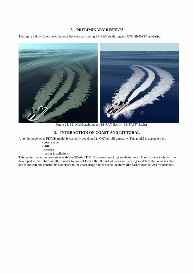
8. PRELIMINARY RESULTS
The figure below shows the coherence between ray tracing SE-RAY rendering and GPU SE-FAST rendering:
Figure 22: SE-Workbench images SE-RAY (Left) – SE-FAST (Right)
9. INTERACTION OF COAST AND LITTORAL
A non homogeneous FETCH model Is currently developed in OKTAL-SE company. This model is dependent on: - coast shape - cliffs - beaches - harbor installations … This model has to be consistent with the SE-AGETIM 3D virtual mock up modeling tool. A set of new tools will be developed in the future month in order to control (when the 3D virtual mock up is being modeled) the local sea state, and to indicate the constraints associated to the coast shape and its special features like harbor installations for instance.

Figure 23: SE-AGETIM marine DB example
10. GP GPU FOR RAY TRACING IMPLEMENTATION
In the frame of the ray tracing rendering, which is more realistic especially with regards to wavelength, OKTAL-SE is currently prototyping GP GPU implementation. The general idea is to use the multiple cores and associated memory that can run in parallel directly on the graphical board (Graphical Process Unit) instead of the CPU. OKTAL-SE tries to have a long-term policy for GP GPU. First trials have been made using OptiX, the Nvidia black box ray tracing application which reaches very impressive performance for the new generation Nvidia 3D graphic boards. OKTAL-SE has also developed a CUDA native application, that can be translated in Open CL and that is a white box. This openness is quite necessary both in term of independence to Nvidia but also to manage the performance at low level, and this typically for complex parts of the SE-RAY SW, such as the implementation of the physical models.
If we make a projection of the 2011 SE Workbench release, for the SE-RAY part, both solutions will be available for the users, CPU or GPU, as shown in the following figure:

SDMSDM
CPU
GPU
1D new acceleration structure
New Raymanagement
New Physics management
1D new acceleration structure
New Raymanagement
New Physics management
1D new acceleration structure
New Raymanagement
New Physics management
1D new acceleration structure
New Raymanagement
New Physics management
Good for validation and debugFully portable
Good for perfomance
Figure 24: SE-Workbench CPU/GP-GPU dual approach
11. CONCLUSION AND PERSPECTIVES
Thanks to these recent developments fully supported by French DGA “Maitrise de l’Information” and MBDA France, SE-Workbench is now fully operational for marine research simulation.
A large community uses SE-Workbench: army, research and industry.
SE-Workbench presents a unique solution in the world that merges three technical complementary approaches that are: CPU, GP-GPU and GPU shaders and that combines the advantages of these three approaches.
A lot of work is still to be done. It mainly concerns the GP GPU implementation for SE-RAY-IR, the GPU shader improvement in term of functionalities and performances, the White Caps modeling thanks to multi-texturing new feature of the SE-Workbench. Plans are made also to improve the atmospheric definition close to water thanks to MATISSE ONERA SW. A coupling with ShipIR SW product could also be very interesting for our customers in the future.
REFERENCES
1. Alain Le Goff, Jean Latger, “Realistic multi spectral simulation including IR simulation”, SPIE Proceedings, Vol. 3694, April 1999 2. Thierry Cathala, Nicolas Douchin, Jean Latger, Karine Caillault, Sandrine Fauqueux, Thierry Huet, Luc Labarre, Claire Malherbe, Bernard Rosier and Pierre Simoneau, “The coupling of MATISSE and the SE-WORKBENCH: a new solution for simulating efficiently the atmospheric radiative transfer and the sea surface radiation”, SPIE 2009 Orlando 3. K. Caillault, S. Fauqueux, C. Bourlier, P. Simoneau, and L. Labarre, “Multi resolution infrared optical properties for gaussian sea surfaces”, Proceedings of the 18th IASTED International Conference: modelling and simulation, 30 Mai - 1 Juin 2007, Montréal, Canada 4. Karine Caillault, Sandrine Fauqueux, Pierre Simoneau, “Multiresolution optical properties for infrared sea surface modeling”, SPIE European Symposium on Remote Sensing, Cardiff, September, 2008 5. W. J. Pierson and L. Moskowitz, "A Proposed Spectral Form for Fully Developed Wind Seas Based on the Similarity Theory of S. A. Kitaigorodskii," J. Geophysical Research, 1964. 6. K. Hasselmann, T. P. Barnett, E. Bouws, H. Carlson, D. E. Cartwright, K. Enke, J. A. Ewing, H. Gienapp, D. E. Hasselmann, P. Kruseman, A. Meerburg, P. Müller, D. J. Olbers, K. Richter, W. Sell, and W. H. Walden, "Measurements of Wind-Wave Growth and Swell Decay During the Joint North Sea Wave Project (JONSWAP)" Deutsche Hydrographische Zeitschrift, 1973