
SE8C Signal DECoDEr - Digitrax, Inc. · PDF fileEach SE8C signal decoder and occupancy...
24
SE8C Signal DECoDEr Features & Specifications n Control signals on your layout: Manually with any LocoNet Throttle and Command Station. Automatically with detection and compatible computer software. n Drives as many as 32 signal heads with popular LED signal types: Bi-color LED searchlights with 2 or 3 leads. Three-LED heads with common anode or common cathode. Can drive B&O or Pennsy-type heads. Designed to model most US signalling systems. Built in current limiting resistors for setting brightness of LEDs. n Simple modular wiring: Modular Plug ‘N Play system. Each Signal Driver Cable drives four heads. Includes sample Signal Driver Cable and Test Signal Mast. n Drives either 8 slow motion turnout machines such as Circuitron’s Tortoise TM OR 8 semaphore signals using slow motion turnout machines. n Provides 16 inputs: 8 control lines for local turnout control. 8 occupancy sensor inputs. n Use with DC or DCC controlled layouts. n A computer & compatible software are necessary to realize the full feature potential of the SE8C. Accessory Products make SE8C installation easy! These items are available for purchase separately: Signal Mast Base Kit: Includes 3 Signal Masts that can be used as Signal Mast Bases in any scale or can be painted and detailed and used as N-scale signal masts. Signal Driver Cable Kit: Materials for making 2 Signal Driver Cables for SE8C. Includes 20’of 10-wire Signal Driver ribbon cable & 8 10-Pin sockets. Signal Mounting Hardware Kit: Under layout mounting hardware for Signal Driver Cables and sockets. 6 metal signal straps and 6 signal spacers. Terminal Strip Mounting Kit: Includes terminal strip board with resistors installed for easy installation. ©2010 Digitrax, Inc. www.digitrax.com 1 Complete Train Control Run Your Trains, Not Your Track!
Transcript of SE8C Signal DECoDEr - Digitrax, Inc. · PDF fileEach SE8C signal decoder and occupancy...
SE8C SignalDECoDEr
Features & Specificationsn Control signals on your layout:
Manually with any LocoNet Throttle and Command Station.
Automatically with detection and compatible computer software.
n Drives as many as 32 signal heads with popular LED signal types:
Bi-color LED searchlights with 2 or 3 leads.
Three-LED heads with common anode or common cathode.
Can drive B&O or Pennsy-type heads.
Designed to model most US signalling systems.
Built in current limiting resistors for setting brightness of LEDs.
n Simple modular wiring:
Modular Plug ‘N Play system.
Each Signal Driver Cable drives four heads.
Includes sample Signal Driver Cable and Test Signal Mast.
n Drives either
8 slow motion turnout machines such as Circuitron’s TortoiseTM OR
8 semaphore signals using slow motion turnout machines.
n Provides 16 inputs:
8 control lines for local turnout control.
8 occupancy sensor inputs.
n Use with DC or DCC controlled layouts.
n A computer & compatible software are necessary to realize the full feature potential of the SE8C.
Accessory Products make SE8C installation easy!These items are available for purchase separately:
Signal Mast Base Kit: Includes 3 Signal Masts that can be used as SignalMast Bases in any scale or can be painted and detailed and used as N-scalesignal masts.
Signal Driver Cable Kit: Materials for making 2 Signal Driver Cables forSE8C. Includes 20’of 10-wire Signal Driver ribbon cable & 8 10-Pin sockets.
Signal Mounting Hardware Kit: Under layout mounting hardware for SignalDriver Cables and sockets. 6 metal signal straps and 6 signal spacers.
Terminal Strip Mounting Kit: Includes terminal strip board with resistorsinstalled for easy installation.
©2010 Digitrax, Inc. www.digitrax.com 1
Complete Train ControlRun Your Trains, Not Your Track!
©2010 Digitrax, Inc. www.digitrax.com 2
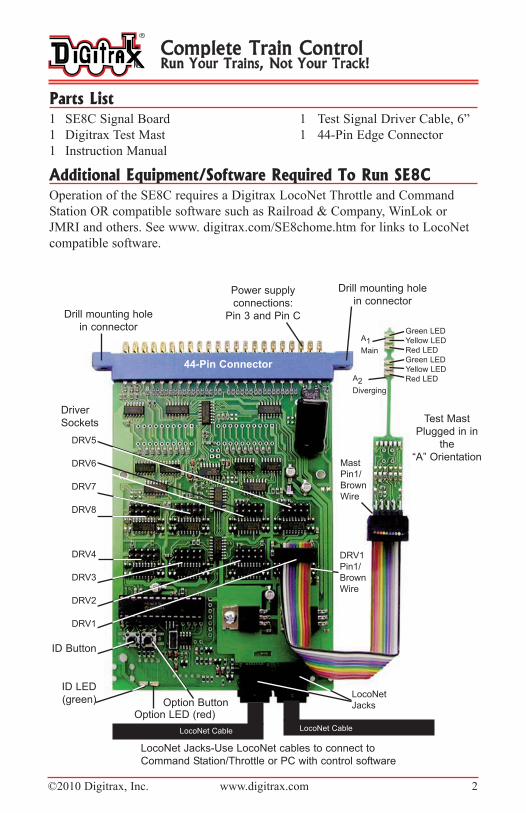
Parts List1 SE8C Signal Board 1 Test Signal Driver Cable, 6”
1 Digitrax Test Mast 1 44-Pin Edge Connector
1 Instruction Manual
Additional Equipment/Software Required To Run SE8COperation of the SE8C requires a Digitrax LocoNet Throttle and Command
Station OR compatible software such as Railroad & Company, WinLok or
JMRI and others. See www. digitrax.com/SE8chome.htm for links to LocoNet
compatible software.
Complete Train ControlRun Your Trains, Not Your Track!
LocoNet Jacks-U se LocoNet cables to connect to
Command Station/Throttle or PC with control software
Power supply
connections:
Pin 3 and Pin C
DRV1
Pin1/
Brown
Wire
44-Pin Connector
Drill mounting hole
in connector
Test Mast
Plugged in in
the
“A” Orientation
Option ButtonOption LED (red)
Mast
Pin1/
Brown
Wire
DRV5
DRV6
DRV7
DRV8
DRV4
DRV3
DRV2
DRV1
Green LED
Yellow LED
Red LED
Green LED
Yellow LED
Red LED
ID Button
ID LED
(green)
Drill mounting hole
in connector
A2
Diverging
A1
Main
LocoNet
Jacks
LocoNet Cable LocoNet Cable
Driver
Sockets
©2010 Digitrax, Inc. www.digitrax.com 3
Introduction to the Digitrax SE8CThe Digitrax Signaling System is organized around the concept of "security
elements" which are similar to what U.S. prototype railroads call "plants." The
Digitrax SE8C signal decoder displays aspects for up to 32 heads for 8 individ-
ual security elements (plants) using either a LocoNet Throttle or a computer
with compatible software. When used with associated occupancy detectors and
compatible software, the SE8C can be set up to protect the turnout as shown by
the example below. The SE8C decodes switch commands from a throttle or
associated software so that the appropriate aspects are displayed on the signal
heads.
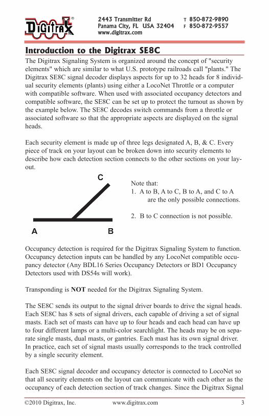
Each security element is made up of three legs designated A, B, & C. Every
piece of track on your layout can be broken down into security elements to
describe how each detection section connects to the other sections on your lay-
out.
Note that:
1. A to B, A to C, B to A, and C to A
are the only possible connections.
2. B to C connection is not possible.
Occupancy detection is required for the Digitrax Signaling System to function.
Occupancy detection inputs can be handled by any LocoNet compatible occu-
pancy detector (Any BDL16 Series Occupancy Detectors or BD1 Occupancy
Detectors used with DS54s will work).
Transponding is NOT needed for the Digitrax Signaling System.
The SE8C sends its output to the signal driver boards to drive the signal heads.
Each SE8C has 8 sets of signal drivers, each capable of driving a set of signal
masts. Each set of masts can have up to four heads and each head can have up
to four different lamps or a multi-color searchlight. The heads may be on sepa-
rate single masts, dual masts, or gantries. Each mast has its own signal driver.
In practice, each set of signal masts usually corresponds to the track controlled
by a single security element.
Each SE8C signal decoder and occupancy detector is connected to LocoNet so
that all security elements on the layout can communicate with each other as the
occupancy of each detection section of track changes. Since the Digitrax Signal
2443 Transmitter Rd T 850-872-9890Panama City, FL USA 32404 F 850-872-9557www.digitrax.com
©2010 Digitrax, Inc. www.digitrax.com 4
System communicates through LocoNet, it does not need DCC to work. The
SE8C signal decoders and BDL16 Series occupancy detectors can communi-
cate directly with other LocoNet devices on the layout, they do not need a
command station for this communication. This means that they can be used on
non LocoNet DCC systems and DC systems where LocoNet is added to sup-
port signaling.
The SE8C lets you control of signals manually from your Digitrax throttles or
automatically through LocoNet compatible computer software such as Railroad
& Company, WinLok and others.
Pre- Installation Set Up & TestingWe recommend testing your new SE8C prior to installation on your layout. The
following testing procedures will help familiarize you with the general opera-
tion of the SE8C. No track power is required for testing, but you will need a
working LocoNet connection and throttle or PC running DCC control software.
Pre-installation Set-Up1. Solder one wire from a 12V AC or 15V DC power supply to Pin 3 and the
second wire from the power supply to the Pin C on the 44-Pin edge connec-tor. This powers the SE8C. Multiple SE8Cs can be powered by a singleshared power supply as long as you provide at least 100mA for each SE8C.This power supply should not power any devices other than SE8C andBDL16 series detectors.
2. Connect a working LocoNet to either LocoNet Jack on the SE8C using aLocoNet cable. These jacks bridge through LocoNet so you can daisy chainfrom one LocoNet device to the next. Your working LocoNet can be fromeither a PC running DCC control software or a LocoNet command stationand throttle.
3. The SE8C is shipped from the factory with the Test Mast and Test SignalDriver Cable already connected to the DRV1 connection on the SE8C readyfor testing. One signal driver cable connector should be plugged into theSE8C board so that the brown wire (Pin 1) is to the right (Figure 1), closestto the edge of the board. The test mast should be plugged into the other con-nector on the cable so the face of the mast is toward you and the brownwire is on the left. This is called the “A” orientation.
Note: There is a small arrowhead on the Signal Driver Cable connectors
over the brown wire that points to Pin 1 of the cable. Pin 1 of the Signal
Mast is indicated by the square pad on the bottom left Pin on the front of
the mast.
4. Power up SE8C. The green ID LED will light up. The red Option LED will
blink when a LocoNet message is seen. The red LEDs on the test mast will
light.
Complete Train ControlRun Your Trains, Not Your Track!
©2010 Digitrax, Inc. www.digitrax.com 5
5. Before testing, be sure the SE8C is set to factory settings. If settings havebeen changed, reset the SE8C to its factory settings as follows:
a. Press and hold the Option Button until the red LED starts to blink. b. Release the button, the red and green LEDs will blink alternately
indicating that you are in Option Switch programming mode.c. Go into SWITCH mode on your throttle or PC.d. Select Switch 20. e. Close and then Throw the switch to reset the factory settings. f. Press and hold the Option button until the red LED stops blinking.g. Release the Option button and the green LED will stay lit.
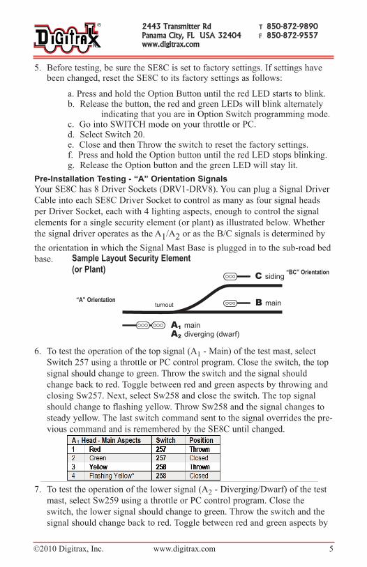
Pre-installation Testing - “a” orientation Signals
Your SE8C has 8 Driver Sockets (DRV1-DRV8). You can plug a Signal Driver
Cable into each SE8C Driver Socket to control as many as four signal heads
per Driver Socket, each with 4 lighting aspects, enough to control the signal
elements for a single security element (or plant) as illustrated below. Whether
the signal driver operates as the A1/A2 or as the B/C signals is determined by
the orientation in which the Signal Mast Base is plugged in to the sub-road bed
base.
6. To test the operation of the top signal (A1 - Main) of the test mast, select
Switch 257 using a throttle or PC control program. Close the switch, the top
signal should change to green. Throw the switch and the signal should
change back to red. Toggle between red and green aspects by throwing and
closing Sw257. Next, select Sw258 and close the switch. The top signal
should change to flashing yellow. Throw Sw258 and the signal changes to
steady yellow. The last switch command sent to the signal overrides the pre-
vious command and is remembered by the SE8C until changed.
7. To test the operation of the lower signal (A2 - Diverging/Dwarf) of the test
mast, select Sw259 using a throttle or PC control program. Close the
switch, the lower signal should change to green. Throw the switch and the
signal should change back to red. Toggle between red and green aspects by
2443 Transmitter Rd T 850-872-9890Panama City, FL USA 32404 F 850-872-9557www.digitrax.com
Sample Layout Security Element
(or Plant)
“A” Orientation
“BC” Orientation

©2010 Digitrax, Inc. www.digitrax.com 6
throwing and closing Sw259. Next, select Sw260 and close the switch. The
lower signal should change to flashing yellow. Throw Sw260 and the signal
changes to a steady yellow.
* Flashing Yellow aspect can be changed with OpSw settings. See SE8C
Option Switch Settings.
Pre-installation Testing - “B/C” orientation Signals
8. Unplug the Test Signal Mast, turn it around so that it faces the oppositedirection relative to the Signal Driver Cable. Pin 1 of the Test Signal Mastwill be plugged into the socket over the black wire of the Signal DriverCable. This is called “B/C” Orientation.
9. To test the operation of the lower signal (B-Main) of the Test Mast, first
select Sw261 using a throttle or PC train control program. Close the switch,
the lower signal should change to green. Throw the switch and the signal
should change back to red. Toggle between red and green aspects by throw-
ing and closing Sw261. Now select Sw262 and close the switch. The lower
signal should change to flashing yellow. Throw Sw262 and the signal
changes to a steady yellow.
10.To test the operation of the upper signal (C-siding) of the test mast, first
select Sw263 using a throttle or PC control program. Close the switch, the
lower signal should change to green. Throw the switch and the signal
should change back to red. Toggle between red and green aspects by throw-
ing and closing Sw263. Now select Sw264 and close the switch. The should
change to flashing yellow. Throw Sw264 and the signal changes to a steady
yellow.
* Flashing Yellow aspect can be changed with OpSw settings. See SE8C
Option Switch Settings.
Complete Train ControlRun Your Trains, Not Your Track!
©2010 Digitrax, Inc. www.digitrax.com 7
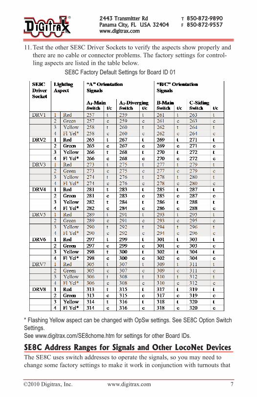
11. Test the other SE8C Driver Sockets to verify the aspects show properly and
there are no cable or connector problems. The factory settings for control-
ling aspects are listed in the table below.
SE8C Factory Default Settings for Board ID 01
* Flashing Yellow aspect can be changed with OpSw settings. See SE8C Option Switch
Settings.
See www.digitrax.com/SE8chome.htm for settings for other Board IDs.
SE8C Address Ranges for Signals and Other LocoNet DevicesThe SE8C uses switch addresses to operate the signals, so you may need to
change some factory settings to make it work in conjunction with turnouts that
2443 Transmitter Rd T 850-872-9890Panama City, FL USA 32404 F 850-872-9557www.digitrax.com
©2010 Digitrax, Inc. www.digitrax.com 8
are already installed on your layout. Be sure that when you configure the SE8C
that the switch address ranges you select to operate the signals do not conflict
with other devices, like DS54s, already installed. We strongly recommend that
you keep accurate documentation of the address ranges used to control all
devices on the layout to avoid conflicts that might cause problems. Without this
record it can be very difficult to debug problems.
The factory default setting for the SE8C’s Board ID is “01” which will control
as many as 8 slow motion turnout machines using switch addresses Sw01 to
Sw08 and 32, 4-aspect signal heads using the signal switch addresses Sw257
through Sw320 (64 consecutive switch addresses). See SE8C Default Settings
for Board ID 01.
Setting the Board ID is the only way to change the range of switch addresses
used to control slow motion turnouts with the SE8C. Signal switch addresses
can be changed from the factory settings using Option Switch 17 (see section
Changing The Signal Control Address Range).
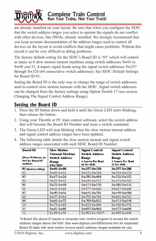
Setting the Board ID1. Press the ID button down and hold it until the Green LED starts blinking,
then release the button.
2. Using your Throttle or PC train control software, select the switch addressthat will become the Board ID Number and issue a switch command.
3. The Green LED will stop blinking when the slow motion turnout addressand signal control address ranges have been updated.
4. The following table details the slow motion turnout and signal switchaddress ranges associated with each SE8C Board ID Number:
*A Board IDs above12 require a computer train control program to access the switch
address ranges above Sw1000. See www.digitrax.com/SE8chome.htm for expanded
Board ID table with slow motion turnout switch address ranges available for use.
Complete Train ControlRun Your Trains, Not Your Track!
©2010 Digitrax, Inc. www.digitrax.com 9
Changing The Signal Control Address RangeWe do not recommend changing the signal control address range unless you
have a very good reason and have taken steps to be certain that changing these
addresses will not affect the operation of other devices on the layout. If you
determine that you need to change the signal control address range use the fol-
lowing steps:
1. Press and hold the Option Button on the SE8C board until the red LEDstarts to blink. Release the Option Button. The red and green LEDs shouldblink alternately indicating that the SE8C is in Option Switch mode. Switchcommands issued while in OpSw mode will change the SE8C’s option set-tings.
2. Using your throttle or PC, select Sw17 and issue a "closed" command. Thistells the SE8C that the next switch command issued will define the new sig-nal control switch address range for this Board ID.
3. Select a switch address that will define the range of 64 addresses that youwish to use to control the signal heads. For example, issuing a “closed”command for Sw685 defines the range Sw641-Sw704.
4. Exit OpSw mode by pressing the Option Button then releasing it when thealternating LED flashing stops.
NOTE: Setting the Board ID to 13-24 will provide a slow motion turnoutmachine switch address range Sw97-Sw192 and signal control switchaddress range of Sw1025-Sw2048. The switch address range Sw1000-Sw2048 can be accessed only by using a computer train control program.
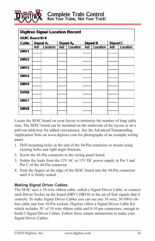
Setting Up The SE8C For Your LayoutWe strongly recommend that you keep an accurate record of all SE8C Board
ID numbers and the switch addresses used to control slow motion turnout
machines and signals. You should also keep track of which signal is associated
with each SE8C board and specifically which Driver Socket on that board con-
trols the signal. This will help in troubleshooting any problems that may occur
during operation. (See sample Signal Location Record Form.)
Each layout device that uses a switch address for control must have a unique
address. If a switch address for any device on your layout falls within the range
of your selected SE8C signal control switch address range, each time a signal
aspect is changed using that switch control address, it will also activate the
other device. When this happens, resolve the conflict by changing one of the
addresses.
The SE8C signal switch address range is set up in groups of 64 addresses. See
Setting the Board ID Section for factory set ranges for each SE8C Board ID.
When changing the factory settings for a Board ID, make sure that you are not
selecting a switch address range already in use by another device on the layout.
2443 Transmitter Rd T 850-872-9890Panama City, FL USA 32404 F 850-872-9557www.digitrax.com
©2010 Digitrax, Inc. www.digitrax.com 10
The useable range of switch addresses is limited by the switch setting device’s
capability to select addresses. For example, the DT300 and DT400/DT402 can
select switch addresses Sw01 through Sw999. A UT1 can only access switch
addresses through Sw99. A DCC computer controlled system can access
through Sw2048.
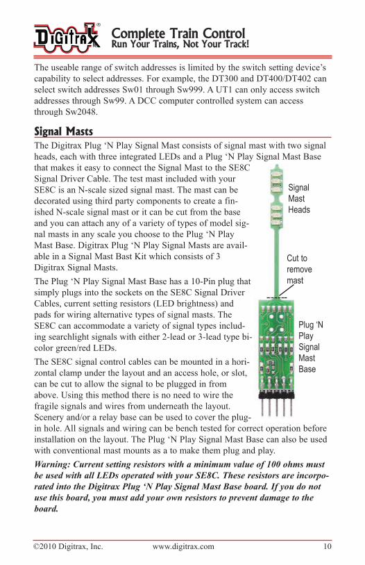
Signal MastsThe Digitrax Plug ‘N Play Signal Mast consists of signal mast with two signal
heads, each with three integrated LEDs and a Plug ‘N Play Signal Mast Base
that makes it easy to connect the Signal Mast to the SE8C
Signal Driver Cable. The test mast included with your
SE8C is an N-scale sized signal mast. The mast can be
decorated using third party components to create a fin-
ished N-scale signal mast or it can be cut from the base
and you can attach any of a variety of types of model sig-
nal masts in any scale you choose to the Plug ‘N Play
Mast Base. Digitrax Plug ‘N Play Signal Masts are avail-
able in a Signal Mast Bast Kit which consists of 3
Digitrax Signal Masts.
The Plug ‘N Play Signal Mast Base has a 10-Pin plug that
simply plugs into the sockets on the SE8C Signal Driver
Cables, current setting resistors (LED brightness) and
pads for wiring alternative types of signal masts. The
SE8C can accommodate a variety of signal types includ-
ing searchlight signals with either 2-lead or 3-lead type bi-
color green/red LEDs.
The SE8C signal control cables can be mounted in a hori-
zontal clamp under the layout and an access hole, or slot,
can be cut to allow the signal to be plugged in from
above. Using this method there is no need to wire the
fragile signals and wires from underneath the layout.
Scenery and/or a relay base can be used to cover the plug-
in hole. All signals and wiring can be bench tested for correct operation before
installation on the layout. The Plug ‘N Play Signal Mast Base can also be used
with conventional mast mounts as a to make them plug and play.
Warning: Current setting resistors with a minimum value of 100 ohms must
be used with all LEDs operated with your SE8C. These resistors are incorpo-
rated into the Digitrax Plug ‘N Play Signal Mast Base board. If you do not
use this board, you must add your own resistors to prevent damage to the
board.
Complete Train ControlRun Your Trains, Not Your Track!
Plug ‘N
Play
Signal
Mast
Base
Cut to
remove
mast
Signal
Mast
Heads

©2010 Digitrax, Inc. www.digitrax.com 11
Customizing the Signal MastsYou can use the Digitrax Signal Mast Base for connecting any signal mast in
any scale you want to use to the Signal Driver Cable.
1. Cut the Digitrax Signal Mast off the Plug ‘N Play Signal Mast Base.
2. Set the angle and height for the new mast and solder it to the large pad pro-vided on the back of the Signal Mast Base. (See figure next page). Or usethe 4 holes in the board for a pair of retaining wires to hold the signal mastin place. Be sure to insulate the Signal Mast Base from the signal you areattaching if there is any chance that it might touch the traces on the circuitboard and cause a short circuit!
3. The Plug ‘N Play Signal Mast Base provides the resistors required for con-necting the LEDs on the signal mast. Solder the wires from your signalmast directly to the associated pads on the Signal Mast Base as indicated inthe following schematics and photos.
For clarity, the following examples use a line name for each Signal Mast Basesolder pad to avoid confusion with wire colors. In the first example, 3/3Signal heads with green, yellow and red LEDs, the line names correspondto the LED colors. One Signal Mast Base must be used for the A1/A2 signalheads (A Orientation) and one for the B and C signal heads (B/COrientation). See figure Sample Layout Security Element (Plant)--for a typi-cal signal location.
Signal Head Examples:
3 over 3 dual "G" type signal heads such as the Tomar H-866, can be con-
nected to a Plug ‘N Play Signal Mast Base (with the signal mast removed). The
white common anode lead (for both heads) connects to Common Lo (Pin 1)
pad and the signal’s longer wires from the red/green/yellow LEDs from the
Lower (dwarf) signal head connect to Red Lo (Pin 7), Green Lo (Pin 3) and
Yellow Lo (Pin 5) pads on the front of the Signal Mast Base. The shorter 3
wires from the upper head connect to the pads on the back Red Hi (Pin 4),
Yellow Hi (Pin 6) and Green Hi (Pin 8).
Single signal heads such as Tomar H-856 (type "G"-3 LED vertical) or H-855
(3 LED target) connect the white common to Common Lo (1) and connect the
3 color leads to the Lo (1, 5, 7) pads for the dwarf signal or the Hi (4, 6, 8)
pads for the mainline signal. The combinations are shown in the schematic.
2-LED signals, such as Tomar N-857 with only red and green LEDs, omit the
yellow pad connection and use the red and green pads for LED control.
2443 Transmitter Rd T 850-872-9890Panama City, FL USA 32404 F 850-872-9557www.digitrax.com
©2010 Digitrax, Inc. www.digitrax.com 12
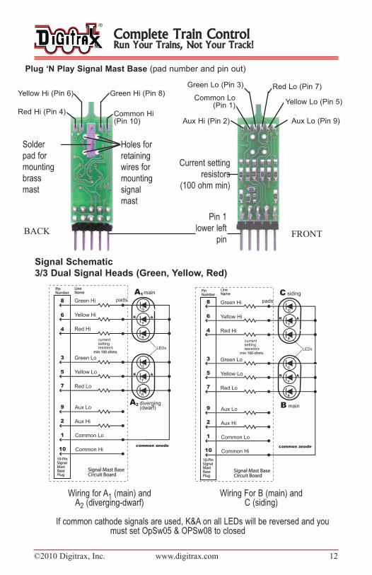
Signal Schematic
3/3 Dual Signal Heads (green, Yellow, red)
Wiring for A1 (main) and Wiring For B (main) andA2 (diverging-dwarf) C (siding)
If common cathode signals are used, K&A on all LEDs will be reversed and youmust set OpSw05 & OPSw08 to closed
main
siding
B
C
Complete Train ControlRun Your Trains, Not Your Track!
Holes for
retaining
wires for
mounting
signal
mast
Plug ‘n Play Signal Mast Base (pad number and pin out)
Solder
pad for
mounting
brass
mast
Red Hi (Pin 4)
Yellow Hi (Pin 6) Green Hi (Pin 8)
Aux Hi (Pin 2)
Common Lo (Pin 1)
Aux Lo (Pin 9)
Yellow Lo (Pin 5)
Common Hi (Pin 10)
Red Lo (Pin 7)Green Lo (Pin 3)
Current setting
resistors
(100 ohm min)
Pin 1
lower left
pinBACK FRONT
©2010 Digitrax, Inc. www.digitrax.com 13
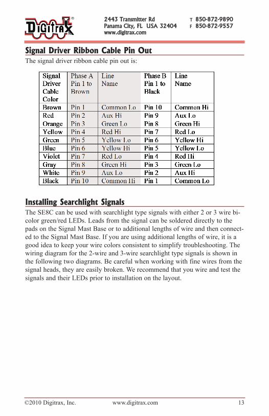
Signal Driver Ribbon Cable Pin OutThe signal driver ribbon cable pin out is:
Installing Searchlight SignalsThe SE8C can be used with searchlight type signals with either 2 or 3 wire bi-
color green/red LEDs. Leads from the signal can be soldered directly to the
pads on the Signal Mast Base or to additional lengths of wire and then connect-
ed to the Signal Mast Base. If you are using additional lengths of wire, it is a
good idea to keep your wire colors consistent to simplify troubleshooting. The
wiring diagram for the 2-wire and 3-wire searchlight type signals is shown in
the following two diagrams. Be careful when working with fine wires from the
signal heads, they are easily broken. We recommend that you wire and test the
signals and their LEDs prior to installation on the layout.
2443 Transmitter Rd T 850-872-9890Panama City, FL USA 32404 F 850-872-9557www.digitrax.com
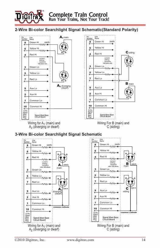
©2010 Digitrax, Inc. www.digitrax.com 14
2-Wire Bi-color Searchlight Signal Schematic(Standard Polarity)
Wiring for A1 (main) and Wiring For B (main) andA2 (diverging or dwarf) C (siding)
3-Wire Bi-color Searchlight Signal Schematic
Wiring for A1 (main) and Wiring For B (main) andA2 (diverging or dwarf) C (siding)
Complete Train ControlRun Your Trains, Not Your Track!

©2010 Digitrax, Inc. www.digitrax.com 15
Installing Position Light Signals And SemaphoresThe SE8C can be used with position light type signals like those used by the
Pennsylvania RR and the B&O/N&W. Leads from the signal can be sol-dered directly to the pads on the Signal Mast Base or to additional lengthsof wire and then connected to the Signal Mast Base. Signals can be eithercommon anode or common cathode types. It’s simpler if you use all thesame type for consistency in the setting up and troubleshooting your layout.If you are using additional lengths of wire it is a good idea to keep yourwire colors consistent to simplify installation and troubleshooting. Thewiring diagrams for the Pennsy and B&O/N&W signals are available atwww.digitrax.com/SE8chome.htm.
The SE8C can also be set up to use the 8 turnout motor drive outputs to sup-port 8 three-position semaphore type signals using slow motion type turnoutmachines, such as the Tortoise™ brand turnout machine. These 8 sema-phore signals are available in addition to the standard 32 LED signal headson the 8 Signal Driver Control Cables and occupy a separate address range.The SE8C automatically sequences the three possible mechanical arm posi-tions to match 3 aspects of red, green and yellow using a position sensefeedback wire from the slow motion turnout machine’s auxiliary contacts.Complete instructions for installing semaphores on your layout areavailable at www.digitrax.com/SE8chome.htm.
Installing The SE8C Board and Signals On Your LayoutTest your signals and SE8C board settings to be sure that everything is working
as expected before installing them on your layout. See previous sections for
information on testing the SE8C board and wiring and testing masts.
It is best to start with a plan for your signal placements noting the location of
each signal head on your layout diagram. Group the signal heads by plant or
other convenient groups of four signal heads to reduce your wiring require-
ments and minimize problems in setup. Keep a record of each signal location
and the SE8C Driver Socket and Signal Driver Cable used to control it. A sam-
ple of the suggested record keeping format follows.
2443 Transmitter Rd T 850-872-9890Panama City, FL USA 32404 F 850-872-9557www.digitrax.com
©2010 Digitrax, Inc. www.digitrax.com 16
Locate the SE8C board on your layout to minimize the number of long cable
runs. The SE8C board can be mounted on the underside of the layout or on a
pull-out table/tray for added convenience. See the Advanced Transponding
Application Note on www.digitrax.com for photographs of an example wiring
panel.
1. Drill mounting holes in the end of the 44-Pin connector or mount usingexisting holes and right angle brackets.
2. Screw the 44-Pin connector to the wiring panel board.
3. Solder the leads from the 12V AC or 15V DC power supply to Pin 3 andPin C of the 44-Pin connector.
4. Push the fingers at the edge of the SE8C board into the 44-Pin connectoruntil it is firmly seated.
Making Signal Driver CablesThe SE8C uses a 10-wire ribbon cable, called a Signal Driver Cable, to connect
each Driver Socket on the board (DRV1-DRV8) to the set of four signals that it
controls. To make Signal Driver Cables you can use any 10 wire, 30 AWG rib-
bon cable and four 10-Pin sockets. Digitrax offers a Signal Driver Cable Kit
which includes 30’ of 10 wire ribbon cable and 8-10 pin connectors, enough to
build 2 Signal Driver Cables. Follow these simple instructions to make your
Signal Driver Cables:
Complete Train ControlRun Your Trains, Not Your Track!

©2010 Digitrax, Inc. www.digitrax.com 17
1. Cut 10-wire ribbon cable to the length you need. When measuring the dis-tance from the SE8C location to the signals, allow enough cable to providefor twisting the cable into position under the layout, securing the cable andconnectors to the sub-roadbed base and to allow plugging in the SignalMast Base. Make the cuts straight and square across the ribbon cable. Use amarker to mark the points where the socket for each signal will be placedon the signal driver cable.
2. Separate the two pieces of the 10-Pin connectors. Be careful not to breakthe latches on the top part of the connectors as you separate them.
3. Lay the ribbon cable into the grooves in the bottom part of the connector.For the connector on the end of the cable, the cable should extend throughthe connector no more than 1/16" beyond the end of the connector. Thecable may be placed in the bottom part of the connecter with the brownwire to the right (shown below) or left as long as the top part is placed withthe Pin 1 indicator arrow over the brown wire for installation.
4. Place the top part of the connector, metal pins toward the cable, over latcheson the bottom part of the connector. The Pin 1 indicator arrow on the side ofthe connector should be over the brown wire.
5. Squeeze the two parts of the connector together around the ribbon cable.The easiest way to do this is in a vise using wood blocks to protect thesocket from being crushed. Repeat the steps for each socket. For makinginstallation easier, the socket can face in either direction, as long as the Pin1 indicator arrow is above the brown wire.
6. Test the completed Signal Driver Cable prior to installation on your layoutusing the procedures detailed in the Pre-Installation Testing ProceduresSection. Once testing is complete, the signal driver cable is ready to beplugged into one of the SE8C’s driver sockets.
You will need eight Signal Driver Cables if you want to hook up all of the 32signals that can be controlled by each SE8C.
2443 Transmitter Rd T 850-872-9890Panama City, FL USA 32404 F 850-872-9557www.digitrax.com
Pin 1
mark
Pin 1
mark
©2010 Digitrax, Inc. www.digitrax.com 18
Installing Signals On Your LayoutLocate the SE8C near the center of a high density signal area on the layout to
minimize the length of the cable runs required. Make up Signal Driver Cables
to match the run requirements for each plant where you plan to install signals.
You can also use the SE8C to control the turnout associated with each plant
using wires from the 44-Pin connector to a slow motion turnout machine.
Alternately, the turnout control capabilities can be used to control semaphores.
See www.digitrax.com/SE8chome.htm for information about installing sema-
phores.
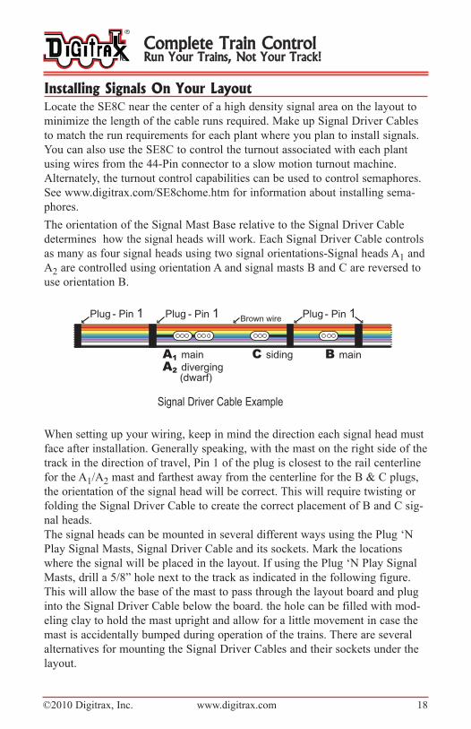
The orientation of the Signal Mast Base relative to the Signal Driver Cable
determines how the signal heads will work. Each Signal Driver Cable controls
as many as four signal heads using two signal orientations-Signal heads A1 and
A2 are controlled using orientation A and signal masts B and C are reversed to
use orientation B.
Signal Driver Cable Example
When setting up your wiring, keep in mind the direction each signal head must
face after installation. Generally speaking, with the mast on the right side of the
track in the direction of travel, Pin 1 of the plug is closest to the rail centerline
for the A1/A2 mast and farthest away from the centerline for the B & C plugs,
the orientation of the signal head will be correct. This will require twisting or
folding the Signal Driver Cable to create the correct placement of B and C sig-
nal heads.
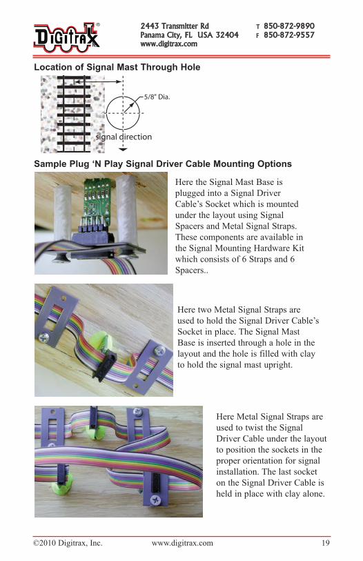
The signal heads can be mounted in several different ways using the Plug ‘N
Play Signal Masts, Signal Driver Cable and its sockets. Mark the locations
where the signal will be placed in the layout. If using the Plug ‘N Play Signal
Masts, drill a 5/8” hole next to the track as indicated in the following figure.
This will allow the base of the mast to pass through the layout board and plug
into the Signal Driver Cable below the board. the hole can be filled with mod-
eling clay to hold the mast upright and allow for a little movement in case the
mast is accidentally bumped during operation of the trains. There are several
alternatives for mounting the Signal Driver Cables and their sockets under the
layout.
Complete Train ControlRun Your Trains, Not Your Track!
©2010 Digitrax, Inc. www.digitrax.com 19
location of Signal Mast Through Hole
Sample Plug ‘n Play Signal Driver Cable Mounting options
2443 Transmitter Rd T 850-872-9890Panama City, FL USA 32404 F 850-872-9557www.digitrax.com
Here the Signal Mast Base is
plugged into a Signal Driver
Cable’s Socket which is mounted
under the layout using Signal
Spacers and Metal Signal Straps.
These components are available in
the Signal Mounting Hardware Kit
which consists of 6 Straps and 6
Spacers..
Here two Metal Signal Straps are
used to hold the Signal Driver Cable’s
Socket in place. The Signal Mast
Base is inserted through a hole in the
layout and the hole is filled with clay
to hold the signal mast upright.
Here Metal Signal Straps are
used to twist the Signal
Driver Cable under the layout
to position the sockets in the
proper orientation for signal
installation. The last socket
on the Signal Driver Cable is
held in place with clay alone.
©2010 Digitrax, Inc. www.digitrax.com 20
Installing Turnouts and Feedback InputThe SE8C will control as many as eight slow motion turnout machines, like
Circuitron’s Tortoise. It also provides as many as eight inputs for detection. The
44 connector pin out is detailed on the following page.
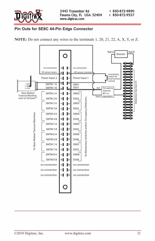
Detection Section inputsDS01 to DS08 (see figure opposite page) are inputs from occupancy detectors
that provide at least +5V (max 22V) when occupied, and 0V when unoccupied.
The SE8C sends occupancy messages to LocoNet when these inputs change. If
these detection section inputs are not disconnected, they will report “unoccu-
pied”. Occupancy reporting can be turned off by changing OpSw 13 to closed.
local Switch inputs for Turnout operationSW01 to SW08 (see figure opposite page) are inputs that allow a local switch
mounted on the layout to operate the slow motion turnout machine. For exam-
ple, SW01 when connected to the +VE sensor common (Pin 2 in figure) will
reverse the voltages on SMTM1A and SMTM1B to change the position of
turnout 1. SW02 controls local turnout 2 , etc. For each connection to +VE sen-
sor common the slow motion turnout machine swaps direction and a Switch
message is sent to LocoNet to report the new position of the turnout.
This local control can be disconnected by setting OpSw 15 to closed, in which
case the 8 slow motion turnout machines can still be controlled by the system
via LocoNet or the DCC track input while the local switch inputs have no
effect.
Disabling Throttle Control of Head aspect Display
To disable Throttle control of head aspect display, use the DCS100’s OpSw 27
with a PC software signal controller that can map out the Signal control
address range as not being controlled from LocoNet/throttles. This same feature
can be used to selectively allow access to parts of the system such as mainline
turnouts.
Complete Train ControlRun Your Trains, Not Your Track!
©2010 Digitrax, Inc. www.digitrax.com 21
Pin outs for SE8C 44-Pin Edge Connector
NOTE: Do not connect any wires to the terminals 1, 20, 21, 22, A, X, Y, or Z.
2443 Transmitter Rd T 850-872-9890Panama City, FL USA 32404 F 850-872-9557www.digitrax.com

©2010 Digitrax, Inc. www.digitrax.com 22
Customizing Your SE8CThe SE8C board can be set up to meet the signaling requirements of your lay-
out using the Option Switch programming mode. To change Options:
1. Press the Option Button on the SE8C board down until the red LED startsto blink, then release the button. The red and green LEDs will blink alter-nately indicating that the SE8C is in Option Switch mode. Switch com-mands issued while in OpSw mode will change the SE8C’s current settings.
2. Using your Throttle or PC, select the option switch you want to change andissue the appropriate command. Refer to the following table to determinewhich option switches and settings to use.
3. Exit OpSw mode by pressing the Option Button then releasing it when thealternating LED flashing stops.
Tech Support for Your SE8CSee www.digitrax.com/SE8chome.htm for our SE8C troubleshooting applica-
tion note BEFORE you call Digitrax tech support. This application note willwalk you through some of the most common tech support issues.
We will be glad to assist you by phone and to verify that your SE8C is workingproperly if it is connected according to the pre-installation set up and testingprocedures described in this manual. Once the SE8C is installed on yourlayout is more difficult for us to assist you with troubleshooting because theSE8C can be used in so many different ways and in so many different set-tings. We are not experts in signaling practice, that is up to you.
Advanced Topics Covered at www.digitrax.com/SE8chome.htm1. Position Light Signals: Pennsylvania RR Permissive Position Signals,
Pennsylvania RR Absolute Position Signals, B&O and N&W RR ColorPosition Signals.
2. Semaphore Signals using slow motion turnout machines.
3. Using 2 aspect mode. The signal control address range will be in blocks of32 instead of 64.
4. Broadcast address control range allows the aspects of all the signal heads tobe set with a single switch command at the broadcast address.
5. How to use SE8C with non-LocoNet DCC layouts.
6. How to use SE8C with DC layouts.
Digitrax ‘No Worries’ Warranty & RepairDigitrax gives a one year “No Worries" Warranty against manufacturing
defects and accidental customer damage on all Digitrax products.
Visit www.digitrax.com for complete warranty details and instructions for
returning items for repair.
Complete Train ControlRun Your Trains, Not Your Track!

©2010 Digitrax, Inc. www.digitrax.com 23
SE8C option Switch Settings
Digitrax, Inc. is not responsible for unintentional
errors or omissions in this document.
2443 Transmitter Rd T 850-872-9890Panama City, FL USA 32404 F 850-872-9557www.digitrax.com

Made in U.S.A.
2443 Transmitter RoadPanama City, FL USA32404www.digitrax.com
T 850 872 9890F 850 872 9557
SE8CSignal Decoder
Available
Computer InterfaceComputer InterfaceDecoder ProgrammerDecoder ProgrammerSound ProgrammerSound Programmer
TM
EEMPIREMPIRE B BUILDERUILDERSuperSuper
00 00 00 00
30
7-8
001-0
000