SE
146
LESSON - 1 THE ROLE OF SOFTWARE Contents 1.0 Aims and Objectives 1.1 Introduction 1.2 The Evolving Role of Software 1.3 Software Characteristics 1.4 Software Applications 1.5 Software Crisis 1.6 Software Myths 1.7 Let Us Sum-Up 1.8 Lesson end Activities 1.9 Check your Progress 1.10 References 1.0 Aims and Objectives In this lesson we focus on the role of software, also examine the characteristics which makes it different from other things that human beings build, observe the crisis and myths of software. After reading this lesson, you should be able to, Identify the software and hardware Distinguish between the hardware and software with various examples Know about software crisis and myths from software engineers and practitioners Know the characteristics and applications of the software 1.1 Introduction Software is the set of instructions encompasses programs that execute within a computer of any size and architecture, documents that encompass hard-copy and virtual forms, and data that combine numbers and text. It also includes representations of pictorial, video, and audio information. Software engineers can build the software and virtually everyone in the industrialized world uses it either directly or indirectly. It is so important because it affects nearly every aspect of our lives and has become pervasive in our commerce, our culture, and our everyday activities. The steps to build the computer software is as the user would like to build any successful product, by applying a process that leads to a high-quality result that meets the needs of the people who will use the product. From the software engineer’s view, the product is may be the programs, documents, and data that are computer software. But
-
Upload
mayuri-srivastava -
Category
Documents
-
view
549 -
download
0
Transcript of SE

LESSON - 1
THE ROLE OF SOFTWARE Contents 1.0 Aims and Objectives 1.1 Introduction 1.2 The Evolving Role of Software 1.3 Software Characteristics 1.4 Software Applications 1.5 Software Crisis 1.6 Software Myths 1.7 Let Us Sum-Up 1.8 Lesson end Activities 1.9 Check your Progress 1.10 References 1.0 Aims and Objectives In this lesson we focus on the role of software, also examine the characteristics which makes it different from other things that human beings build, observe the crisis and myths of software. After reading this lesson, you should be able to,
Identify the software and hardware Distinguish between the hardware and software with various examples Know about software crisis and myths from software engineers and
practitioners Know the characteristics and applications of the software
1.1 Introduction
Software is the set of instructions encompasses programs that execute within a computer of any size and architecture, documents that encompass hard-copy and virtual forms, and data that combine numbers and text. It also includes representations of pictorial, video, and audio information. Software engineers can build the software and virtually everyone in the industrialized world uses it either directly or indirectly. It is so important because it affects nearly every aspect of our lives and has become pervasive in our commerce, our culture, and our everyday activities.
The steps to build the computer software is as the user would like to build any
successful product, by applying a process that leads to a high-quality result that meets the needs of the people who will use the product. From the software engineer’s view, the product is may be the programs, documents, and data that are computer software. But
from the user’s viewpoint, the product is the resultant information that somehow makes the user’s world better. QUICK
Software’s impact on the society and culture continues to be profound. As its importance grows, the software community continually attempts to develop technologies that will make it easier, faster, and less expensive to build high-quality computer programs. Some of these technologies are targeted at a specific application domain like web-site design and implementation; others focus on a technology domain such as object-oriented systems and still others are broad-based like operating systems such as LINUX.
However, a software technology has to develop useful information. The
technology encompasses a process, a set of methods, and an array of tools called as software engineering. 1.2 The Evolving Role of Software
Nowadays, software plays a major role with dual activity. It is a product like a vehicle. As a product, it delivers the computing potential embodied by computer hardware or a network of computers that are accessible by local hardware. Whether the product or software resides within a mobile phone or operates inside a mainframe computer, software is an information transformer likely to produce, manage, acquire, modify, display or transmit the information. The software
provides good product with useful information transforms the data so that it can be more useful in a local context manages business information to enhance competitiveness provides a gateway to worldwide networks like internet
The role of computer software has undergone significant change over a time span
of little more than 50 years. 1.3 Software Characteristics
To make the difference from other things or product, it is important to examine the characteristics of software. When hardware is built, the human creative process may be analysis, design, construction, testing is ultimately translated into a physical form where as build a new computer, the initial sketches, formal design drawings, and bread boarded prototype evolve into a physical product such as chips, circuit boards, power supplies, etc.
Software is a logical related rather than a physical system. So that the software have distinct characteristics but the hardware is not so, it is only the peripherals or devices or components.
Character 1: Software is developed or engineered, it is not manufactured in the Classical Sense.
Although some similarities exist between software development and hardware
manufacture, the two activities are fundamentally different. In both the activities, high quality is achieved through good design, but the manufacturing phase for hardware can introduce quality problems that are nonexistent or easily corrected for software. Both the activities are dependent on people, but the relationship between people is totally varying. These two activities require the construction of a "product" but the approaches are different. Software costs are concentrated in engineering which means that software projects cannot be managed as if they were manufacturing. Character 2: Software does not wear out
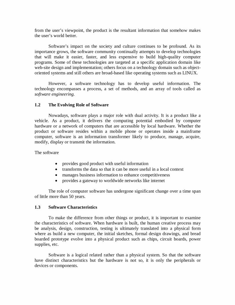
The figure 1.1 shows the relationship between failure rate and time. Consider the failure rate as a function of time for hardware. The relationship is called the bathtub curve, indicates that hardware exhibits relatively high failure rates early in its life, defects are corrected and the failure rate drops to a steady-state level for some period of time. As time passes, however, the failure rate rises again as hardware components suffer from the cumulative affects of dust, vibration, abuse, temperature extremes, and many other environmental maladies. So, stated simply, the hardware begins to wear out.
Figure 1.1 Relationship between failure rate and time
Software is not susceptible to the environmental maladies that cause hardware to
wear out. In theory, therefore, the failure rate curve for software should take the form of the “idealized curve” like a zig-zag form. Undiscovered defects will cause high failure rates early in the life of a program. However, the implication is clear software doesn't wear out. But it does deteriorate. Before the curve can return to the original steady-state failure rate, another change is requested, causing the curve to spike again. Slowly, the minimum failure rate level begins to rise—the software is deteriorating due to change.

Figure 1.2 Idealized and actual failure curves for software
When a hardware component wears out, it is replaced by a spare part unlike the
software spare parts. The software failure indicates an error in design or in the process through which design as translated into machine executable code. Therefore, software maintenance involves more complexity than hardware maintenance. Character 3: Although the industry is moving toward component-based assembly,
most software continues to be custom built
Consider the manner in which the control hardware for a computer-based product is designed and built. The design engineer draws a simple schematic of the digital circuitry, does some fundamental analysis to assure that proper function will be achieved, and then goes to the shelf where catalogs of digital components exist.
Each integrated circuit (called an IC or a chip) has a part number, a defined and validated function, a well-defined interface, and a standard set of integration guidelines. After each component is selected, it can be ordered off the shelf. As an engineering discipline evolves, a collection of standard design components is created. Standard screws and off-the-shelf integrated circuits are standard components that are used by mechanical and electrical engineers to design new systems.
The reusable components have been created so that the engineer can concentrate
on the truly innovative elements of a design, that is, the parts of the design that represent something new. In the hardware world, component reuse is a natural part of the engineering process.
A software component should be designed and implemented so that it can be reused in many different programs. In the 1960s, we built scientific subroutine libraries that were reusable in a broad array of engineering and scientific applications. These subroutine libraries reused well-defined algorithms in an effective manner but had a limited domain of application and not extended algorithm only but included data structure too. Modern reusable components encapsulate both data and the processing applied to the data, enabling the software engineer to create new applications from reusable parts.

1.4 Software Applications
Software is pre-specified set of procedural steps like an algorithm. Information content and determinacy are important factors in determining the nature of a software application [1].
Information Content is to the meaning also the form of incoming and outgoing
information. There are many business applications use highly structured input data and produce formatted reports.
Information Determinacy is the predictability of the order and timing of information. For instance, an engineering analysis program accepts data that have a predefined order, executes the analysis algorithm(s) without interruption, and produces resultant data in report or graphical format. Such applications are determinate. A multiuser operating system, accepts inputs that have varied content and arbitrary timing, executes algorithms that can be interrupted by external conditions, and produces output that varies as a function of environment and time. Applications with these characteristics are indeterminate.
The various categories of software applications are:
System software: A collection of programs written to service other programs are called system software. Examples are compilers, editors, and file management utilities. Other systems applications such as operating system components, drivers, and telecommunications processors process largely indeterminate data. Real-time software: Software that monitors, analyzes and controls real-world events as they occur is called real time. Elements of real-time software include a data gathering component that collects and formats information from an external environment. A analysis component that transforms information as required by the application. A control/output component that responds to the external environment, and a monitoring component that coordinates all other components so that real-time response can be maintained. Business software: The largest single software application area is Business information processing. Discrete systems like payroll, accounts receivable or payable, inventory has evolved into management information system software that accesses one or more large databases containing business information. Applications in this area restructure existing data in a way that facilitates business operations or management decision making. In addition to that conventional data processing application, business software applications also encompass interactive computing. Engineering and scientific software: Engineering and scientific software have been characterized by number crunching algorithms. Applications range from astronomy to volcanology, from automotive stress analysis to space shuttle orbital dynamics, and from

molecular biology to automated manufacturing. However, modern applications within the engineering/scientific area are moving away from conventional numerical algorithms. Computer-aided design, system simulation, and other interactive applications have begun to take on real-time and system software characteristics. Embedded software: Embedded software resides in read-only memory. It is used to control products and systems for the consumer and industrial markets. Embedded software can perform very limited and esoteric functions such as keypad control for a microwave oven or provide significant function and control capability like digital functions in an automobile such as fuel control, dashboard displays, and braking systems. Personal computer software. The personal computer software is playing major role in the software market. The sample applications are word processing, spreadsheets, computer graphics, multimedia, entertainment, database management, personal and business financial applications, external network, and database access. Web-based software. The Web pages retrieved by a browser are software that incorporates executable instructions like CGI, HTML, Perl, or Java and data may be in the form of hypertext and a variety of visual and audio formats. In essence, the network becomes a massive computer providing an almost unlimited software resource that can be accessed by anyone with a modem. Artificial intelligence software. Artificial intelligence software makes use of non-numerical algorithms to solve complex problems that are not amenable to computation or straightforward analysis. Expert systems, also called knowledge based systems, pattern recognition like image and voice, artificial neural networks, theorem proving and game playing is representative of applications within this category. 1.5 Software Crisis
Many industry observers have characterized the problems associated with software development as a crisis. The experts have recounted the impact of some of the more spectacular software failures that have occurred over the past decade. Yet, the great successes achieved by the software industry have led many to question whether the term software crisis is still appropriate.
Robert Glass [3] states that the failure stories and exception reporting, spectacular
failures in the midst of many successes. From the Webster's Dictionary, crisis is defined as a turning point in the course of anything; decisive or crucial time, stage or event. In terms of overall software quality and the speed with which computer-based systems and products are developed, there has been no "turning point," no "decisive time," only slow, evolutionary change, punctuated by explosive technological changes in disciplines associated with software.
Affliction is defined as anything causing pain or distress. It is far more accurate to describe the problems we have endured in the software business as a chronic affliction than a crisis. Regardless of what we call it, the set of problems that are encountered in the development of computer software is not limited to software that doesn't function properly. Rather, the affliction encompasses problems associated with how we develop software, how we support a growing volume of existing software, and how we can expect to keep pace with a growing demand for more software.
1.6 Software Myths
Many causes of a software affliction can be traced to a mythology during the development of software. Software myths propagated misinformation and confusion. Software myths had a number of attributes that made them insidious. Today, most knowledgeable professionals recognize myths for what they are misleading attitudes that have caused serious problems for managers and technical people alike. However, old attitudes and habits are difficult to modify, and remnants of software myths are still believed. Management myths. Managers with software responsibility, like managers in most disciplines, are often under pressure to maintain budgets, keep schedules from slipping, and improve quality. Like a drowning person who grasps at a straw, a software manager often grasps at belief in a software myth, if that belief will lesson the pressure. Myth: We already have a book that's full of standards and procedures for building software, won't that provide my people with everything they need to know? Reality: The book of standards may very well exist, but is it used? Are software practitioners aware of its existence? Does it reflect modern software engineering practice? Is it complete? Is it streamlined to improve time to delivery while still maintaining a focus on quality? In many cases, the answer to all of these questions is no. Myth: My people have state-of-the-art software development tools, after all, we buy them the newest computers. Reality: It takes much more than the latest model mainframe, workstation, or PC to do high-quality software development. Computer-aided software engineering (CASE) tools are more important than hardware for achieving good quality and productivity, yet the majority of software developers still do not use them effectively. Myth: If we get behind schedule, we can add more programmers and catch up is called the Mongolian horde concept. Reality: Software development is not a mechanistic process like manufacturing. In the words of Brooks [2]: "adding people to a late software project makes it later." At first, this statement may seem counterintuitive. However, as new people are added, people who were working must spend time educating the newcomers, thereby reducing the amount of
time spent on productive development effort. People can be added but only in a planned and well-coordinated manner. Myth: If I decide to outsource the software project to a third party, I can just relax and let that firm build it. Reality: If an organization does not understand how to manage and control software projects internally, it will invariably struggle when it outsources software projects. Customer myths. A customer who requests computer software may be a person at the next desk, a technical group down the hall, the marketing/sales department, or an outside company that has requested software under contract. In many cases, the customer believes myths about software because software managers and practitioners do little to correct misinformation. Myths lead to false expectations (by the customer) and ultimately, dissatisfaction with the developer. Myth: A general statement of objectives is sufficient to begin writing programs we can fill in the details later. Reality: A poor up-front definition is the major cause of failed software efforts. A formal and detailed description of the information domain, function, behavior, performance, interfaces, design constraints, and validation criteria is essential. These characteristics can be determined only after thorough communication between customer and developer. Myth: Project requirements continually change, but change can be easily accommodated because software is flexible. Reality: It is true that software requirements change, but the impact of change varies with the time at which it is introduced. Figure 1.3 illustrates the impact of change. If serious attention is given to up-front definition, early requests for change can be accommodated easily. The customer can review requirements and recommend modifications with relatively little impact on cost. When changes are requested during software design, the cost impact grows rapidly.

Figure 1.3 The impact of change
Resources have been committed and a design framework has been established.
Change can cause upheaval that requires additional resources and major design modification, that is, additional cost. Changes in function, performance, interface, or other characteristics during implementation (code and test) have a severe impact on cost. Change, when requested after software is in production, can be over an order of magnitude more expensive than the same change requested earlier. Practitioner's myths. Myths that are still believed by software practitioners have been fostered by 50 years of programming culture. During the early days of software, programming was viewed as an art form. Old ways and attitudes die hard. Myth: Once we write the program and get it to work, our job is done. Reality: Someone once said that "the sooner you begin 'writing code', the longer it'll take you to get done." Industry data indicate that between 60 and 80 percent of all effort expended on software will be expended after it is delivered to the customer for the first time. Myth: Until I get the program "running" I have no way of assessing its quality. Reality: One of the most effective software quality assurance mechanisms can be applied from the inception of a project—the formal technical review. Software reviews are a "quality filter" that have been found to be more effective than testing for finding certain classes of software defects. Myth: The only deliverable work product for a successful project is the working program. Reality: A working program is only one part of a software configuration that includes many elements. Documentation provides a foundation for successful engineering and, more important, guidance for software support.

Myth: Software engineering will make us create voluminous and unnecessary documentation and will invariably slow us down. Reality: Software engineering is not about creating documents. It is about creating quality. Better quality leads to reduced rework. And reduced rework results in faster delivery times. Many software professionals recognize the fallacy of the myths just described. Regrettably, habitual attitudes and methods foster poor management and technical practices, even when reality dictates a better approach. Recognition of software realities is the first step toward formulation of practical solutions for software engineering. 1.7 Let Us Sum-Up
In this lesson, we have described the definition of software, the major responsibility in the software companies, from the user’s perspective as well as the others perspectives how the software are characterized with minimal crisis and myths also discussed.
1.8 Lesson end Activities
1. Provide some examples of software. Are there any differences between software and hardware? Justify?
2. Find the distinct possible examples of Application, Languages, Packages and
Software? 1.9 Check your Progress
1. There are many differences while comparing the software and hardware. The
software is a set of instructions which is delivering the result what user wants where as the peripherals like keyboard, mouse, CPU, memory unit, motherboard and other devices or parts are called hardware.
2. There are differences between the application, language, package and software. The program, one which has enhanced facility also some of the proved conditions
that will not change in future is called language. Some examples are C, C++, Pascal, Fortran, COBOL, Visual basic and so.
The Project, one which is supplying the results what the user or customer wants in
the limited scope is called application. Some examples are Payroll system, Banking Management and Inventory control and so on.
The project or program may include the defined structures also flexible to apply
in the language is called package. Some examples are Microsoft office which includes

several applications such as Microsoft Word, Microsoft Excel, Microsoft Power point and Microsoft Outlook and so on.
The program one which has a consistency and quality to cope with other
supportive programs or often say set of instructions is called software. Some examples are compiler, operating system, interpreter, translator, C compiler and so on. 1.10 References
1. Roger S. Pressman, Software Engineering – A Practitioners Approach, Sixth Edition, McGraw –Hill, 2005.
2. Brooks, F., The Mythical Man-Month, Addison-Wesley, 1975. 3. Glass, R.L., Software Runaways, Prentice-Hall, 1997.

LESSON – 2
A PROCESS FRAME WORK Contents 2.0 Aims and Objectives 2.1 Introduction 2.2 Project Types 2.3 Framework Activities 2.4 Let Us Sum Up 2.5 Lesson end Activities 2.6 Check your Progress 2.7 References
2.0 Aims and Objectives
In many software companies delivering a new product for the society from various discipline such as finance, commerce, economics, statistics, accountancy, production, manufacturing and engineering which needs to improve their business activities with advanced features. Thus the project and process play a major role in the business. The objective of set of activities or process has to solve the respective problem. In this lesson, the process framework and models are introduced. 2.1 Introduction
Software projects span many different types of organizations, a variety of different application areas, and a wide range of technologies; it is likely that any process model developed for use on these projects will have to be adapted to local circumstances. The intent of the Adaptable Process Model is to:
1. provide a common process framework for all projects; 2. define generic framework activities that are applicable across all projects; 3.define a process model that can be adapted to local requirements, standards, and culture; 4. define a process model that is appropriate regardless of the paradigm like linear sequential life cycle model, prototyping, evolutionary model that has chosen for process flow; 5. provide guidance to project teams that will enable these teams to adapt the APM intelligently to their environment. The process model is adapted by considering two characteristics of the project: (1) project type, and
(2) a set of adaptation criteria that defines the degree of rigor with which software engineering is to be applied. 2.2 Project Types Project type refers to the characteristics of the project. In this context, the following project types are defined:
Concept Development Projects that are initiated to explore some new business concept or application of some new technology,
New Application Development Projects that are undertaken as a
consequence of a specific customer request.
Application Enhancement Projects that occur when existing software
under goes major modifications to function, performance or interfaces that are observable by the end-user,
Application Maintenance Projects that correct, adapt, or extend existing
software in ways that may not be immediately obvious to the end user.
Reengineering Projects that are undertaken with the intent of rebuilding an existing system in whole or in part. Web Application Development Projects that are undertaken when web
sites and related internet-based applications must be developed.
Although each of the projects types differs in subtle and profound ways, all can be approached using a consistent software engineering framework. These are described in the following section. 2.3 Framework Activities
An effective process model should define a small set of framework activities that are always applicable, regardless of project type. The APM defines the following set of framework activities: Project Definition - tasks required to establish effective communication between developer and customer(s) and to define requirements for the work to be performed Planning - tasks required to define resources, timelines and other project related information and assess both technical and management risks

Engineering and Construction - tasks required to create one or more representations of the software (can include the development of executable models, i.e., prototypes or simulations) and to generate code and conduct thorough testing Release - tasks required to install the software in its target environment, and provide customer support (e.g., documentation and training) Customer use - tasks required to obtain customer feedback based on use and evaluation of the deliverables produced during the release activity
Each of the above framework activities will occur for every project. However, the set of tasks otherwise called as task set that is defined for each framework activity will vary depending upon the project type and the degree of rigor selected for the project. 2.4 Let Us Sum-up Software has a sufficient environment to solve any sort of situation in the various disciplines. Nowadays it is a good partner of using such a lot more thing in the world. Software yields the property of time consumption and effort due to avoiding unwanted things by making the aid of manual practice. 2.5 Lesson End Activities 1. Find the differences of software process and software project.
2. Can you suggest the framework activities of your developed project or any real time application?
2.6 check your progress 1. A collection of activities in the software is called software process whether it may be the simple or complex program where as the sequences of process is known as a software project. 2. Try on your own real time example like pay roll system of employees working under the control of any management. 2.7 References
1.Roger S. Pressman, Software Engineering – A Practitioners Approach, Fifth Edition, McGraw –Hill, 2005. 2. Ian Sommerville, Software Engineering, Sixth Edition, Pearson Education, 2001.

LESSON – 3
SOFTWARE PROCESS MODELS Contents 3.0 Aims and Objectives 3.1 Introduction 3.2 Software Product 3.3 Software Process
3.3.1 Critical Practices 3.3.2 Generic Software Engineering Phases 3.3.3 Software Engineering Activities 3.3.4 Software Engineering Institute (SEI) Capability Maturity Model (CMM)
3.4 Software Process Models 3.4.1 Systems Development Life Cycle 3.4.2 Rapid Application Development 3.4.3 Joint Application Development 3.4.4 Extreme Programming 3.4.5 Waterfall Model 3.4.6 Spiral Model
3.5 System Analysis 3.6 System Design 3.7 System Implementation 3.8 Let Us Sum Up 3.9 Lesson end Activities 3.10 Check Your Progress 3.11 References 3.0 Aims and Objectives
When the user has work to build a product or system, it is important to go through a series of predictable steps or a road map that helps to create a timely, high quality result. The road map is called a 'software process. At the end of this lesson, your should be able to understand about software process.
3.1 Introduction
The roadmap to building high quality software products is software process. Software processes are adapted to meet the needs of software engineers and managers as they undertake the development of a software product. A software process provides a framework for managing activities that can very easily get out of control. Different projects require different software processes. The software engineer's work products are produced as consequences of the activities defined by the software process. The best
indicators of how well a software process has worked are the quality, timeliness, and long-term viability of the resulting software product.
3.2 Software Product
The Software scope may include the context, information objectives, function and performance of the product. The problem of software product must decomposed by the user or programmer.
3.3 Software Process
The Process model chosen must be appropriate for the customers and developers, characteristics of the product, and project development environment. Initially, the Project planning phase begins with melding the product and the process. Each function to be engineered must pass though the set of framework activities defined for a software organization. The activity or work tasks may vary but the common process framework is invariant. The job of the software engineer is to estimate the resources required to move each function though the framework activities to produce each work product.
Project decomposition begins when the project manager tries to determine how to
accomplish each CPF activity. Generally, the Project has to start on the right foot, maintain momentum, Track progress, Make smart decisions and Conduct a postmortem analysis. The Principle of project development is to fulfill the following queries.
Why is the system being developed? What will be done by When? Who is responsible for a function? Where they are organizationally located? How will the job be done technically and managerially? How much of each resource is needed?
3.3.1 Critical Practices
Formal risk management Empirical cost and schedule estimation Metric-based project management Earned value tracking Defect tracking against quality targets People-aware program management
3.3.2 Generic Software Engineering Phases
Definition phase - focuses on what (information engineering, software project planning, requirements analysis).

Development phase - focuses on how (software design, code generation, software testing).
Support phase - focuses on change (corrective maintenance, adaptive maintenance, perfective maintenance, preventative maintenance).
3.3.3 Software Engineering Activities
Software project tracking and control Formal technical reviews Software quality assurance Software configuration management Document preparation and production Reusability management Measurement Risk management Common Process Framework Software engineering work tasks Project milestones Work products Quality assurance points
3.3.4 Software Engineering Institute (SEI) Capability Maturity Model (CMM) Level 1: Initial Level 2: Repeatable (able to repeat earlier successes) Level 3: Defined
(management and engineering processes documented, standardized, and integrated into organization-wide software process) Level 4: Managed
(software process and products are quantitatively understood and controlled using detailed measures) Level5:Optimizing (continuous process improvement is enabled by quantitative feedback from the process and testing innovative ideas) 3.4 Software Process Models
Though ebusiness technologies represent a significant opportunity for a business to establish an advantage over their competitors, implementing these systems is difficult and many projects fail. They may fail for a number of reasons. The team of people involved may prove disfunctional. The intended users of the system may refuse to accept
the change that goes along with it. Key errors may occur in the planning or requirements gathering stage and so on.
In order to get these projects right a strict methodology must be followed. These projects are not unlike a large-scale civic project like building a bridge and some may last for a year or more. The more effort and care that goes into the early planning phases, the smoother it goes down near the testing and implementation phase. Here, along with a site that further explains it is an illustration of one version of the Systems Development Life Cycle (SDLC).
3.4.1 Systems Development Life Cycle
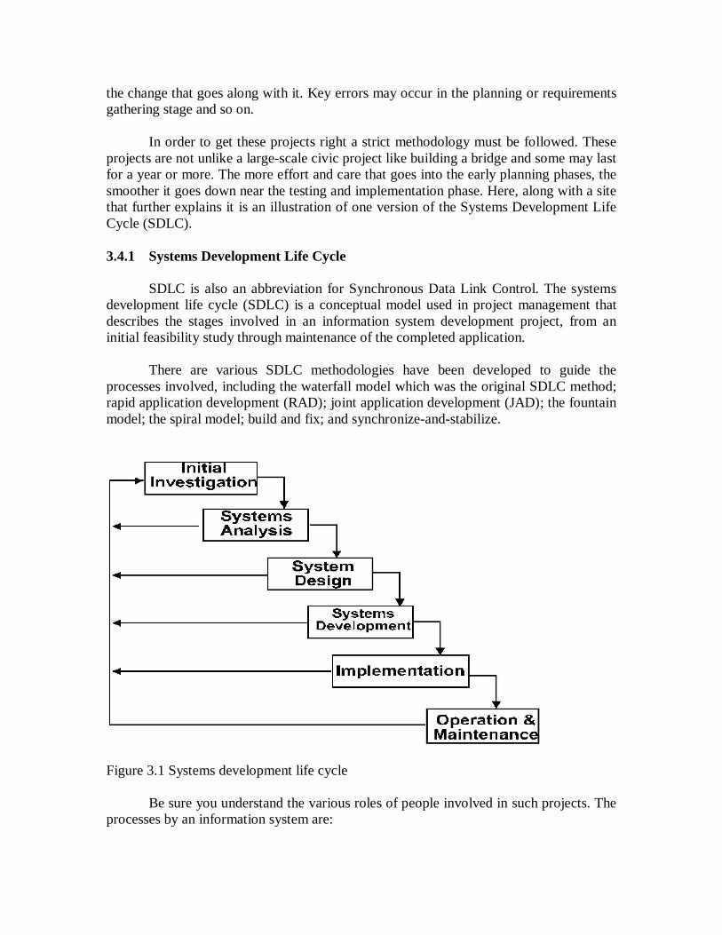
SDLC is also an abbreviation for Synchronous Data Link Control. The systems development life cycle (SDLC) is a conceptual model used in project management that describes the stages involved in an information system development project, from an initial feasibility study through maintenance of the completed application.
There are various SDLC methodologies have been developed to guide the
processes involved, including the waterfall model which was the original SDLC method; rapid application development (RAD); joint application development (JAD); the fountain model; the spiral model; build and fix; and synchronize-and-stabilize.
Figure 3.1 Systems development life cycle
Be sure you understand the various roles of people involved in such projects. The processes by an information system are:

designed created implemented maintained replaced
Large organizations will have various information systems at different stages in
their life cycle. Most of the "activity" in the SDLC is in the maintenance stage. Frequently, several models are combined into some sort of hybrid methodology.
Documentation is crucial regardless of the type of model chosen or devised for any application, and is usually done in parallel with the development process. Some methods work better for specific types of projects, but in the final analysis, the most important factor for the success of a project may be how closely the particular plan was followed. In general, an SDLC methodology follows the following steps: 1. The existing system is evaluated. Deficiencies are identified. This can be done by interviewing users of the system and consulting with support personnel. 2. The new system requirements are defined. In particular, the deficiencies in the existing system must be addressed with specific proposals for improvement. 3. The proposed system is designed. Plans are laid out concerning the physical construction, hardware, operating systems, programming, communications, and security issues. 4. The new system is developed. The new components and programs must be obtained and installed. Users of the system must be trained in its use, and all aspects of performance must be tested. If necessary, adjustments must be made at this stage. 5. The system is put into use. This can be done in various ways. The new system can phased in, according to application or location, and the old system gradually replaced. In some cases, it may be more cost-effective to shut down the old system and implement the new system all at once. 6. Once the new system is up and running for a while, it should be exhaustively evaluated. Maintenance must be kept up rigorously at all times. Users of the system should be kept up to date concerning the latest modifications and procedures.
The types of process models are categorized as, Linear Sequential Model or water fall model Prototyping Model Rapid Application and Development (RAD) Model Incremental Model Spiral Model Win-Win Spiral Model - eliciting software requirements defined through
negotiation between customer and developer, where each party attempts to balance technical and business constraints
Concurrent Development Model - similar to spiral model often used in development of client/server applications

Component Based Development - spiral model variation in which applications are built from prepackaged software components called classes
Formal Methods Model - rigorous mathematical notation used to specify, design, and verify computer-based systems
Fourth Generation (4GT) Techniques - software tool is used to generate the source code for a software system from a high level specification representation
3.4.2 Rapid Application Development
Rapid Application Development is a concept that products can be developed faster and of higher quality through:
Gathering requirements using workshops or focus groups Prototyping and early, reiterative user testing of designs The re-use of software components A rigidly paced schedule that defers design improvements to the next
product version Less formality in reviews and other team communication
Some companies offer products that provide some or all of the tools for RAD
software development. The concept can be applied to hardware development as well. These products include requirements gathering tools, prototyping tools, computer-aided software engineering tools, language development environments such as those for the Java platform, groupware for communication among development members, and testing tools. RAD usually embraces object-oriented programming methodology, which inherently fosters software re-use. The most popular object-oriented programming languages, C++ and Java, are offered in visual programming packages often described as providing rapid application development. 3.4.3 Joint Application Development
JAD (Joint Application Development) is a methodology that involves the client or end user in the design and development of an application, through a succession of collaborative workshops called JAD sessions. Chuck Morris and Tony Crawford, both of IBM, developed JAD in the late 1970s and began teaching the approach through workshops in 1980. The JAD approach, in comparison with the more traditional practice, is thought to lead to faster development times and greater client satisfaction, because the client is involved throughout the development process.
In comparison, in the traditional approach to systems development, the developer
investigates the system requirements and develops an application, with client input consisting of a series of interviews. A variation on JAD, rapid application development creates an application more quickly through such strategies as using fewer formal methodologies and reusing software components.

3.4.4 Extreme Programming
Extreme Programming (XP) is a pragmatic approach to program development that emphasizes business results first and takes an incremental, get-something-started approach to building the product, using continual testing and revision. The conception of Kent Beck, who has written a book about it, XP proceeds with the view that code comes first. Beck emphasizes that in order to write the code, however, you have to write a test for it first so that you will know when your code succeeds. Beck also introduces the relatively novel idea that code should be written by pairs of programmers, forcing the main programmer to describe the code to the other programmer and perhaps to stimulate further ideas.
Beck calls Extreme Programming a "lightweight methodology" that challenges the assumption that getting the software right the first time is the most economical approach in the long run. Beck's fundamental idea is to start simply, build something real that works in its limited way, and then fit it into a design structure that is built as a convenience for further code building rather than as an ultimate and exhaustive structure after thorough and time-consuming analysis. Rather than specialize, all team members write code, test, analyze, design, and continually integrate code as the project develops. Because there is much face-to-face communication, the need for documentation is minimized, according to Beck. 3.4.5 Waterfall Model
The waterfall model is a popular version of the systems development life cycle model for software engineering. Often considered the classic approach to the systems development life cycle, the waterfall model describes a development method that is linear and sequential. Waterfall development has distinct goals for each phase of development. Imagine a waterfall on the cliff of a steep mountain. Once the water has flowed over the edge of the cliff and has begun its journey down the side of the mountain, it cannot turn back. It is the same with waterfall development. Once a phase of development is completed, the development proceeds to the next phase and there is no turning back.
The advantage of waterfall development is that it allows for departmentalization
and managerial control. A schedule can be set with deadlines for each stage of development and a product can proceed through the development process like a car in a carwash, and theoretically, be delivered on time. Development moves from concept, through design, implementation, testing, installation, troubleshooting, and ends up at operation and maintenance. Each phase of development proceeds in strict order, without any overlapping or iterative steps.
The disadvantage of waterfall development is that it does not allow for much reflection or revision. Once an application is in the testing stage, it is very difficult to go back and change something that was not well-thought out in the concept stage. Alternatives to the waterfall model include joint application development, rapid application development, synch and stabilize, build and fix, and the spiral model.

The Prototyping Model is a systems development method in which a prototype is
built, tested, and then reworked as necessary until an acceptable prototype is finally achieved from which the complete system or product can now be developed. This model works best in scenarios where not all of the project requirements are known in detail ahead of time. It is an iterative, trial-and-error process that takes place between the developers and the users. There are several steps in the Prototyping Model: The new system requirements are defined in as much detail as possible. This usually involves interviewing a number of users representing all the departments or aspects of the existing system.
A. A preliminary design is created for the new system. B. A first prototype of the new system is constructed from the preliminary design.
This is usually a scaled-down system, and represents an approximation of the characteristics of the final product.
C. The users thoroughly evaluate the first prototype, noting its strengths and
weaknesses, what needs to be added, and what should to be removed. The developer collects and analyzes the remarks from the users.
D. The first prototype is modified, based on the comments supplied by the users, and
a second prototype of the new system is constructed.
E. The second prototype is evaluated in the same manner as was the first prototype.
F. The preceding steps are iterated as many times as necessary, until the users are satisfied that the prototype represents the final product desired.
G. The final system is constructed, based on the final prototype.
H. The final system is thoroughly evaluated and tested. Routine maintenance is
carried out on a continuing basis to prevent large-scale failures and to minimize downtime.
3.4.6 Spiral Model
The spiral model, also known as the spiral lifecycle model, is a systems development method used in information technology. This model of development combines the features of the prototyping model and the waterfall model. The spiral model is favored for large, expensive, and complicated projects. The steps in the spiral model can be generalized as follows:

1. The new system requirements are defined in as much detail as possible. This usually involves interviewing a number of users representing all the external or internal users and other aspects of the existing system. 2. A preliminary design is created for the new system. 3. A first prototype of the new system is constructed from the preliminary design. This is usually a scaled-down system, and represents an approximation of the characteristics of the final product. 4. A second prototype is evolved by a fourfold procedure:
Evaluating the first prototype in terms of its strengths, weaknesses, and
risks Defining the requirements of the second prototype Planning and designing the second prototype Constructing and testing the second prototype
5. At the customer's option, the entire project can be aborted if the risk is deemed too great. Risk factors might involve development cost overruns, operating-cost miscalculation, or any other factor that could, in the customer's judgment, result in a less-than-satisfactory final product. 6. The existing prototype is evaluated in the same manner as was the previous prototype, and, if necessary, another prototype is developed from it according to the fourfold procedure outlined above. 7. The preceding steps are iterated until the customer is satisfied that the refined prototype represents the final product desired. 8. The final system is constructed, based on the refined prototype. 9. The final system is thoroughly evaluated and tested. Routine maintenance is carried out on a continuing basis to prevent large-scale failures and to minimize downtime.
3.5 Systems Analysis
A system is an organised group of related components, and the interactions between them. Systems analysis is the process of studying an existing system to determine how it works and how it meets existing needs .Usually the aim of the analysis is the development of a better replacement system. The process of systems analysis includes:
data collection like documents, interviews, questionnaires, observation data analysis systems requirements recommendations
The role of the Systems Analyst is given in this section. A systems analyst should,

carries out the analysis that leads to the specification of the new system
designs the new system coordinates the development of the new system, including
management of the project liaises with clients, users and developers acts as a crucial change agent within the organization
3.6 System Design
System design is the process of developing a plan for an "improved" system that,
Maintains the functionality of the existing system. Adds new functionality Builds upon the users' knowledge base 'Leverages' (as much as is appropriate) the current investment in
hardware and software
1. May involve the use of prototype systems 2. May involve the use of Computer-aided Software Engineering or CASE Tools 3. Turns preliminary design into detailed design specifications by focusing on,
Input and output requirements File organization Database structures System management System Development
System development is the process of turning the detailed plan into a functioning
system, it has
software development component testing system testing volume testing usability testing creation of documentation
3.7 System Implementation
System implementation is the process of "installing" the system, that follows,
software and hardware installation necessary conversions

user training auditing maintenance
3.8 Let Us Sum-up
Generally, the software development cycle comprised the phases like Analysis, design, coding and implementation, operation and maintenance. When applying these principles in developing software the activities become easy to follow by the user and customer .
3.9 Lesson End Activities
1. Can you exercise with familiar real time application if any for the SDLC? 2. Can you make a comparison of models like waterfall and spiral, which model is most followed in the software project development?
3.10 Check your progress
1. In the section 3.4.1, we have the steps of SDLC. Compare with your real time example.
3.11 References
1.Roger S. Pressman, Software Engineering – A Practitioners Approach, Fifth Edition, McGraw –Hill, 2005. 2. Ian Sommerville, Software Engineering, Sixth Edition, Perason Education, 2001.
LESSON – 4
AGILE PROCESS MODEL Contents 4.0 Aims and Objectives 4.1 Introduction - General concepts and principles
4.1.1 Model with a Purpose 4.1.2 Maximize Stakeholder ROI 4.1.3 Travel Light 4.1.4 Multiple Models 4.1.5 Rapid Feedback 4.1.6 Assume Simplicity 4.1.7 Embrace Change 4.1.8 Incremental Change 4.1.9 Quality Work 4.1.10 Working Software Is Your Primary Goal 4.1.11 Supplementary Principles
4.2 Human Issues 4.3 Agile methods
4.3.1 XP -Extreme Programming 4.3.2 Scrum Methodology 4.3.3 Crystal Methodology 4.3.4 Rational or Unified Process
4.4 Let Us Sum Up 4.5 Check your Progress 4.6 Referemces 4.0 Aims and Objectives
Agile software engineering combines a philosophy and a set of development guidelines. The philosophy encourages customer satisfaction and early incremental delivery of software, small but highly motivated project teams, informal methods with minimal software engineering work products and overall development simplicity. The development guidelines stress delivery over analysis and design, and active and continuous communication between developers and customers. The categories of agile process are presented at each section. 4.1 Introduction - General concepts and principles
Agile Modeling is a practice-based methodology for effective modeling and documentation of software-based systems. Simply put, Agile Modeling (AM) is a collection of values, principles, and practices for modeling software that can be applied on a software development project in an effective and light-weight manner. As you see in Figure 4.1 AM is meant to be tailored into other, full-fledged development

methodologies such as XP or RUP, enabling you to develop software process which truly meets your needs. The techniques of AM, in particular Agile Model Driven Development (AMDD), enable you to scale agile software development to very complex situations.
Principles and practices of Agile Modeling (AM)
Other techniques (ex: Database refactoring )
A base Software Process (ex: XP, RUP, DSDM) Software Process (User)
Figure 4.1. Agile Model exhibits other software processes.
Agile Modeling (AM) defines a collection of core and supplementary principles
that when applied on a software development project set the stage for a collection of modeling practices. Some of the principles have been adopted from eXtreme Programming (XP) and are well documented in Extreme Programming Explained, which in turn adopted them from common software engineering techniques. For the most part the principles are presented with a focus on their implications to modeling efforts and as a result material adopted from XP may be presented in a different light. The Core Principles includes the following constraints.
4.1.1 Model with a Purpose
Many developers worry about whether their artifacts such as models, source code or documents are detailed enough or if they are too detailed, or similarly if they are sufficiently accurate. The first step is to identify a valid purpose for creating a model and the audience for that model, then based on that purpose and audience develop it to the point where it is both sufficiently accurate and sufficiently detailed.
Once a model has fulfilled its goals you're finished with it for now and should
move on to something else, such as writing some code to show that the model works. This principle also applies to a change to an existing model: if you are making a change, perhaps applying a known pattern, then you should have a valid reason to make that change. An important implication of this principle is that you need to know your audience, even when that audience is yourself.
4.1.2 Maximize Stakeholder ROI
Your project stakeholders are investing resources like time, money, facilities, and so on to have software developed that meets their needs. Stakeholders deserve to invest their resources the best way possible and not to have resources frittered away by your team. Furthermore, they deserve to have the final say in how those resources are invested or not invested. If it was your resources, would you want it any other way?
4.1.3 Travel Light
Every artifact that you create, and then decide to keep, will need to be maintained over time. If you decide to keep seven models, then whenever a change occurs you will need to consider the impact of that change on all seven models and then act accordingly. If you decide to keep only three models then you clearly have less work to perform to support the same change, making you more agile because you are traveling lighter. Similarly, the more complex/detailed your models are, the more likely it is that any given change will be harder to accomplish.
Every time you decide to keep a model you trade-off agility for the convenience of having that information available to your team in an abstract manner. Never underestimate the seriousness of this trade-off. Someone trekking across the desert will benefit from a map, a hat, good boots, and a canteen of water they likely won't make it if they burden themselves with hundreds of gallons of water, a pack full of every piece of survival gear imaginable, and a collection of books about the desert. Similarly, a development team that decides to develop and maintain a detailed requirements document, a detailed collection of analysis models, a detailed collection of architectural models, and a detailed collection of design models will quickly discover they are spending the majority of their time updating documents instead of writing source code.
4.1.4 Multiple Models
You potentially need to use multiple models to develop software because each model describes a single aspect of your software. “What models are potentially required to build modern-day business applications?” Considering the complexity of modern day software, you need to have a wide range of techniques in your intellectual modeling toolkit to be effective. An important point is that you don't need to develop all of these models for any given system, but that depending on the exact nature of the software you are developing you will require at least a subset of the models. Different systems, different subsets. Just like every fixit job at home doesn't require you to use every tool available to you in your toolbox, over time the variety of jobs you perform will require you to use each tool at some point. Just like you use some tools more than others, you will use some types of models more than others. 4.1.5 Rapid Feedback
The time between an action and the feedback on that action is critical. By working with other people on a model, particularly when you are working with a shared modeling technology such as a whiteboard, CRC cards, or essential modeling materials such as sticky notes you are obtaining near-instant feedback on your ideas. Working closely with your customer, to understand the requirements, to analyze those requirements, or to develop a user interface that meets their needs, provides opportunities for rapid feedback.
4.1.6 Assume Simplicity
As you develop you should assume that the simplest solution is the best solution. Don't overbuild your software, or in the case of AM don't depict additional features in your models that you don't need today. Have the courage that you don't need to over-model your system today, that you can model based on your existing requirements today and refactor your system in the future when your requirements evolve. Keep your models as simple as possible. 4.1.7 Embrace Change
Requirements evolve over time. People's understanding of the requirements change over time. Project stakeholders can change as your project moves forward, new people are added and existing ones can leave. Project stakeholders can change their viewpoints as well, potentially changing the goals and success criteria for your effort. The implication is that your project's environment changes as your efforts progress, and that as a result your approach to development must reflect this reality. 4.1.8 Incremental Change
An important concept to understand with respect to modeling is that you don't
need to get it right the first time, in fact, it is very unlikely that you could do so even if you tried. Furthermore, you do not need to capture every single detail in your models, you just need to get it good enough at the time. Instead of futilely trying to develop an all encompassing model at the start, you instead can put a stake in the ground by developing a small model, or perhaps a high-level model, and evolve it over time in an incremental manner. 4.1.9 Quality Work
Nobody likes sloppy work. The people doing the work don't like it because it's something they can't be proud of, the people coming along later to refactor the work don't like it because it's harder to understand and to update, and the end users won't like the work because it's likely fragile and/or doesn't meet their expectations. 4.1.10 Working Software Is Your Primary Goal
The goal of software development is to produce high-quality working software that meets the needs of your project stakeholders in an effective manner. The primary goal is not to produce extraneous documentation, extraneous management artifacts, or even models. Any activity that does not directly contribute to this goal should be questioned and avoided if it cannot be justified in this light.

Enabling The Next Effort Is Your Secondary Goal:
Your project can still be considered a failure even when your team delivers a working system to your users – part of fulfilling the needs of your project stakeholders is to ensure that your system robust enough so that it can be extended over time. As Alistair Cockburn likes to say, when you are playing the software development game your secondary goal is to setup to play the next game. Your next effort may be the development of the next major release of your system or it may simply be the operations and support of the current version you are building. To enable it you will not only want to develop quality software but also create just enough documentation and supporting materials so that the people playing the next game can be effective.
Factors that you need to consider include whether members of your existing team
will be involved with the next effort, the nature of the next effort itself, and the importance of the next effort to your organization. In short, when you are working on your system you need to keep an eye on the future. 4.1.11 Supplementary Principles Content Is More Important Than Representation. Any given model could have several ways to represent it. For example, a UI specification could be created using Post-It notes on a large sheet of paper, as a sketch on paper or a whiteboard, as a "traditional" prototype built using a prototyping tool or programming language, or as a formal document including both a visual representation as well as a textual description of the UI. An interesting implication is that a model does not need to be a document. Even a complex set of diagrams created using a CASE tool may not become part of a document, instead they are used as inputs into other artifacts, very likely source code, but never formalized as official documentation. The point is that you take advantage of the benefits of modeling without incurring the costs of creating and maintaining documentation. Open and Honest Communication. People need to be free, and to perceive that they are free, to offer suggestions. This includes ideas pertaining to one or more models, perhaps someone has a new way to approach a portion of the design or has a new insight regarding a requirement; the delivery of bad news such as being behind schedule; or simply the current status of their work. Open and honest communication enables people to make better decisions because the quality of the information that they are basing them on is more accurate. 4.2 Human Issues
Regardless of the quality of team management, or client management, a team is doomed if its players cannot collaborate in an effective manner. How than, can we create a situation where by a group of developers can be introduced to an agile process, and grow to embrace this change? The answer includes understanding, education, and communication.

Asking a developer working within a heavy weight process, or alone, to abandon
their current process and adopt a completely foreign one is asking them to take an enormous leap of faith. We are asking them to abandon a process that they know and understand and step outside of their comfort zone. For developers eager to partake in an agile process the step is welcome. Others will approach it with caution and some will approach it with fierce opposition. If an agile process is not carefully introduced, some developers may fiercely fight this change, while others will embrace it without fully understanding it.
The paradigm shift that these developers need to make in order to become effective members of an agile team can not be trivialized. Underestimating the difficulty that some developers will have making this shift is a grave mistake. Conversely other developers will believe that they have made the shift when in fact they do not fully understand the new process or the principles behind it. To successfully introduce an agile process we need to harness, and direct, the enthusiasm of eager converts while tempering the opposition of those that resist change. We need to manage people through the paradigm shift that is required to become an effective member of an agile team.
In some instances, developers will make the shift very quickly, for others it will take longer and for some this shift may be impossible. I suspect that the ease at which the shift is made may be based on many factors including experience, attitude, self-confidence and the level of trust that they have in the person or persons who are introducing this process. When we ask people to follow a new process we are asking them to trust our abilities, our experiences, and us. If they lack this trust they will not want to accept the risks associated with this change. We must listen to their fears and work hard to understand the real or perceived risks felt by the individuals on the team.
The risks associated with this change will vary from person to person. What are we asking them to give up by working in an agile process? What are they risking? What do they fear? Well, there are many possibilities, consider the following. An older more experienced developer may be assisted by a junior developer. Is there a loss of face, does the older developer feel threatened? Does a developer lack confidence in his code, does he believe that others will find it flawed or poorly written. Does the developer believe that their code is far superior to that of anyone else on the team and that by sharing it with the team it will be degraded? Is a person afraid to admit that they don’t know it all? Do they want to work on their own with their headphones on? Are they uncomfortable because they are being asked to work on a small unit of work while perhaps they do not understand or know the full scope of the system under design? The risks or fears that might be felt by a developer are many and to that person they are very real. A person can not hide in an agile process and for many that is a very frightening prospect.
Restraining the eager convert can be as difficult, though much more fun, than dealing with an unwilling participant. These converts may not understand why other team members "don't get it". Their unbridled enthusiasm may be threatening to other members of the team. It is also possible for them to make misleading or incorrect

comments about the process being introduced. "We're doing XP. We run unit tests and pair program". While done with the best intent such comments and behavior indicate that the agile process is not fully understood.
Whether it is fear, or lack of understanding, the effects of these two states inhibit the introduction of an agile process. We must understand the fears of developers, and know what it is that they do not understood, so that we can mitigate the risks associated with these two states through education. Education requires effective communication. So the successful introduction on an agile process requires, understanding, education, and communication. 4.3Agile methods The term 'agile' refers to a philosophy of software development. Under this broad umbrella sits many more specific approaches such as Extreme Programming, Scrum, Lean Development, etc. Each of these more particular approaches has its own ideas, communities and leaders. Each community is a distinct group of its own but to be correctly called agile it should follow the same broad principles. Each community also borrows from ideas and techniques from each other. Many practitioners move between different communities spreading different ideas around - all in all it's a complicated but vibrant ecosystem.
Agile Manifesto the term 'agile' got hijacked for this activity in early 2001 when a bunch of people who had been heavily involved in this work got together to exchange ideas and came up with the Manifesto for Agile Software Development.
4.3.1 XP - Extreme Programming During the early popularity of agile methods in the late 1990's, Extreme Programming was the one that got the lion's share of attention. In many ways it still does. The roots of XP lie in the Smalltalk community, and in particular the close collaboration of Kent Beck and Ward Cunningham in the late 1980's. Both of them refined their practices on numerous projects during the early 90's, extending their ideas of a software development approach that was both adaptive and people-oriented. Kent continued to develop his ideas during consulting engagements, in particular the Chrysler C3 project, which has since become known as the creation project of extreme programming. He started using the term 'extreme programming' around 1997.
During the late 1990's word of Extreme Programming spread, initially through descriptions on newsgroups and Ward Cunningham's wiki, where Kent and Ron Jeffries spent a lot of time explaining and debating the various ideas. Finally a number of books were published towards the end of the 90's and start of 00's that went into some detail explaining the various aspects of the approach.

XP begins with five values like Communication, Feedback, Simplicity, Courage, and Respect. It then elaborates these into fourteen principles and again into twenty-four practices. The idea is that practices are concrete things that a team can do day-to-day, while values are the fundamental knowledge and understanding that underpins the approach. Values without practices are hard to apply and can by applied in so many ways that it's hard to know where to start. Practices without values are rote activities without a purpose. Both values and practices are needed, but there's a big gap between them - the principles help bridge that gap.
Many of XP's practices are old, tried and tested techniques, yet often forgotten by
many, including most planned processes. As well as resurrecting these techniques, XP weaves them into a synergistic whole where each one is reinforced by the others and given purpose by the values. One of the most striking, as well as initially appealing to me, is its strong emphasis on testing. While all processes mention testing, most do so with a pretty low emphasis. However XP puts testing at the foundation of development, with every programmer writing tests as they write their production code. The tests are integrated into a continuous integration and build process which yields a highly stable platform for future development. XP's approach here, often described under the heading of Test Driven Development (TDD) has been influential even in places that haven't adopted much else of XP. 4.3.2 Scrum Methodology Scrum also developed in the 80's and 90's primarily with OO development circles as a highly iterative development methodology. It's most well known developers were Ken Schwaber, Jeff Sutherland, and Mike Beedle. Scrum concentrates on the management aspects of software development, dividing development into thirty day iterations called 'sprints' and applying closer monitoring and control with daily scrum meetings. It places much less emphasis on engineering practices and many people combine its project management approach with extreme programming's engineering practices. 4.3.3 Crystal Methodology Alistair Cockburn has long been one of the principal voices in the agile community. He developed the Crystal family of software development methods as a group of approaches tailored to different size teams. Crystal is seen as a family because Alistair believes that different approaches are required as teams vary in size and the criticality of errors changes. Despite their variations all crystal approaches share common features. All crystal methods have three priorities: safety in project outcome, efficiency, habitability. They also share common properties, of which the most important three are: Frequent Delivery, Reflective Improvement, and Close Communication. The habitability priority is an important part of the crystal mind-set. Alistair's quest is looking for what is the least amount of process you can do and still succeed with an

underlying assumption of low-discipline that is inevitable with humans. As a result Alistair sees Crystal as requiring less discipline that extreme programming, trading off less efficiency for a greater habitability and reduced chances of failure. 4.3.4 Rational or Unified Process
Another well-known process to have come out of the object-oriented community is the Rational Unified Process sometimes just referred to as the Unified Process. The original idea was that like the UML unified modeling languages the UP could unify software processes. Since RUP appeared about the same time as the agile methods, there's a lot of discussion about whether the two are compatible. RUP is a very large collection of practices and is really a process framework rather than a process. Rather than give a single process for software development it seeks to provide a common set of practices for teams to choose from for an individual project. As a result a team's first step using RUP should be to define their individual process, or as RUP calls it, a development case.
The key common aspects of RUP is that it is Use Case Driven, iterative, and
architecture centric. If compare the descriptions of RUP usage, that range from rigid waterfall with 'analysis iterations' to picture perfect agile. So the desire of people to market the RUP as the single process led to a result where people can do just about anything and call it RUP - resulting in RUP being a meaningless phrase 4.4 Let Us Sum-up
Agile process is one of the advanced model which is followed by software Engineers. It has a Philosophy to develop a model, Agile modeling is a practice based methodology for effective modeling and documentation of Software based systems. Thus we identified the purpose of model, maximum stakeholder, travel light, using multiple models with feedback.
4.5 Lesson End Activities 1. Describe the core principles of extreme programming. 2. Is there any other supplementary principles available if you identify, make
a list of them.
4.6 Check your progress See the section 4.3.1. for the better understanding.
4.7 References 1.Roger S. Pressman, Software Engineering – A Practitioners Approach, Fifth Edition, McGraw –Hill, 2005. 2. Ian Sommerville, Software Engineering, Sixth Edition, Perason Education, 2001.

LESSON – 5
APPLYING WEB ENGINEERING Contents 5.0 Aims and Objectives 5.1 Introduction
5.1.1 Web Quality Requirements 5.1.2 WebApp Enabling Technologies 5.1.3 Technical Elements for Web-Based Design 5.1.4 Web App Architectural Structures
5.2 Evolution of the Web 5.3 Categories of Web Applications
5.3.1 Web Development Practices 5.3.2 Web Development is Different
5.4 Let Us Sum-up 5.5 Lesson end Activities 5.6 Check your Progress 5.7 References 5.0 Aims and Objectives
The Lesson describes Web engineering (WebE) as the process used to create high quality Web-based applications (webApp). As Web based applications become increasingly integrated in business strategies (e.g. e-commerce) the need to build reliable, usable, and adaptable systems grows in importance. Web engineering is not a perfect clone of software engineering, but it draws heavily on many of software engineering's principles and management activities. 5.1 Introduction
The Web engineering process begins with the formulation of the problem to be solved by the Web based application. The project is planned and the Web based application requirements are analyzed. Architectural, navigational, and interface design are conducted. The system is implemented using specialized languages and tools associated with the Web. Web based applications tend to be highly evolutionary, so mechanisms for configuration management, quality control, and maintenance must be established early. Web engineering relies on formal technical reviews to assess the quality of the analysis and design models. Specialized reviews are conducted to assess the usability of the Web based application. Testing is applied to uncover errors in content, functionality, and compatibility.

Attributes of web applications Network intensive Content-driven Continuous evolution Immediacy Security Aesthetics
The Web Engineering Application Categories are,
Informational read only content provided with simple navigation Downloads user downloads information from server Customizable user customizes content to specific needs Interaction community of users communicate using chat rooms,
bulletin boards, or instant messaging User input users complete on-line forms to communicate need Transaction-oriented user makes request fulfilled by WebApp -
places an order Service-oriented application provides service to user, e.g. helps
user determine mortgage payment Portal application directs users to other web content or services Database access user queries a large database and extracts
information Data warehousing user queries large collection of databases and
extracts information 5.1.1 Web Quality Requirements
Usability Functionality Reliability Efficiency Maintainability
5.1.2 WebApp Enabling Technologies
Component-based development (CORBA, COM/DCOM, JavaBeans)
Security (encryption, firewalls, etc.) Internet standards (HTML, XML,SGML)

5.1.3 Technical Elements for Web-Based Design
Design principles and methods - high modularity, low coupling, information hiding, stepwise refinement, OO design methods
Golden rules - design heuristics for hypermedia applications Design Patterns can be applied to WebApp functional elements, documents,
graphics, and general aesthetics Templates provide reusable skeletal frameworks for any design pattern or
document used within the WebApp 5.1.4 Web App Architectural Structures
Linear structures Grid structures Hierarchical structures Networked or "pure" web structure
Depends on webbased systems and applications, their performance, reliability and
quality have become paramount importance and the expectations of and demands placed on web applications have increased significantly over the years. As a result, the design, development, deployment and maintenance of web based systems have become more complex and difficult to manage. Though massive amounts of Web development and maintenance continue to take place, most of them are carried out in adhoc manner, resulting in poor quality websystems and applications. Problems such as outdated or irrelevant information, difficulties in using the web site and finding relevant information of interest, slow of response, web site crashes, and security breaches are common. We encounter these kinds of problems because Web developers failed to address users’ needs and issues such as content management, maintenance, performance, security, and scalability of web applications. They also often overlook important non technical considerations such as copyright and privacy. Many web developers seem to think that web application development is just simple web page creation using HTML or Web development software such as Front Page or Dreamweaver and embodying few images and –linking documents and web pages. Though certain simple applications such as personal web pages, seminar announcements, and simple online company brochures that call for simple content presentation and navigation fall into this category, many web applications are complex and are required to meet an array of challenging requirements which change and evolve. There is more to web application development than visual design and user interface. It involves planning, web architecture and system design, testing, quality assurance and performance evaluation, and continual update and maintenance of the systems as the

requirements and usage grow and develop. Hence, ad hoc development is not appropriate for large, complex web systems, and it could result in serious problems: the delivered systems are not what the user wants, they are not maintainable and scalable, and hence have short useful life; they often do not provide desired levels of performance and security; and/or most web systems are often much behind schedule and overrun the budget estimates. More importantly, many enterprises and organizations cannot afford to have faulty web systems or tolerate downtime or inconsistent or stale content/information. The problems in the Web become quickly visible and frustrate the users, possibly costing the enterprises heavily in terms of financial loss, lost customer and loss of reputation. As is often said, “We cannot hide the problems on the Web.” Unfortunately, despite being faced with these problems and challenges, most web application development still continues to be ad hoc, chaotic, failure prone, and un-satisfactory. And this could get worse as more inherently complex web systems and applications that involve interaction with many other systems or components pervade us and our dependence on them increases. To successfully build large scale, complex web based systems and applications, web developers need to adopt a disciplined development process and a sound methodology, use better development tools, and follow a set of good guidelines. The emerging discipline of web engineering addresses these needs and focuses on successful development of web based systems and applications, while advocating a holistic, disciplined approach to Web development. Web Engineering uses scientific, engineering, and management principles and systematic approaches to successfully develop, deploy, and maintain high quality web systems and applications. It aims to bring web based system development under control, minimise risks and improve quality, maintainability, and scalability of web applications. The essence of web engineering is to successfully manage the diversity and complexity of web application development, and hence, avoid potential failures that could have serious implications. Following a brief outline of the evolution of the Web and the categorisation of Web applications based on their functionality, this Lesson examines current Web develop-ment practices and their limitations, and emphasises the need for a holistic, disciplined approach to Web development. It then presents an overview of Web engineering, describes an evolutionary Web development process, discusses considerations in Web design and recommends ten key steps for successful development. In conclusion, it offers perspectives on Web Engineering and highlights some of the challenges facing Web developers and Web engineering researchers.

5.2 Evolution of the Web
The Web has become closely ingrained with our life and work in just a few years. From its initial objective of facilitating easy creation and sharing of information among a few scientists using simple web sites that consisted primarily of hyperlinked text documents, the web has grown very rapidly in its scope and extent of use, supported by constant advances in Internet and web technologies and standards. In 10 years, the number of web sites dramatically has grown from 100 to over 45 million.
Enterprises, travel and hospitality industries, banks, educational and training institutions, entertainment businesses and governments use large scale web based systems and applications to improve, enhance and/or extend their operations. Ecommerce has become global and widespread. Traditional legacy information and database systems are being progressively migrated to the Web. Modern Web applications run on distributed and heterogeneous computer systems. Furthermore, fuelled by recent advances in wireless technologies and portable computing and communication devices, a new wave of mobile web applications are rapidly emerging. The Web has changed our lives and work at every level, and this trend will continue for the foreseeable future.
The evolution of the web has brought together some disparate disciplines such as media, information science, and information and communication technology, facilitating easy creation, maintenance, sharing, and use of different types of information from anywhere, any time, and using a variety of devices such as desktop and note book computers, pocket PCs, personal digital assistants (PDAs), and mobile phones. Contributions of each of these disciplines to the evolution and growth of the web are: Media:
Integration of different types of media such as data, text, graphics, images, audio and video, and their presentation (animation, 3D visualisation); different types of interaction and channels of communications (one to one, one to many, many to one, and many to many). Information science:
Information organisation, presentation, indexing, retrieval, aggregation, and management; and collaborative and distributed content creation. Information and communication technology and networking:
Efficient and cost-effective storage, retrieval, processing, and presentation of information; infrastructures that facilitate transfer and sharing of data and information; wired and wireless Internet communication; and personalised and context aware web applications.

Table 5.1. Categories of Web applications based on functionality Functionality/Category Examples Informational Online newspapers, product catalogues, newsletters, manuals, reports, online classifieds, online books Interactive Registration forms, customized information presentation, online games
Transactional Online shopping (ordering goods and services), online
banking, online airline reservation, online payment of bills Workflow oriented Online planning and scheduling, inventory management, status monitoring, supply chain management Collaborative work Distributed authoring systems, collaborative design environments tools Online communities, Discussion groups, recommender systems, online marketplaces marketplaces, emalls (electronic shopping malls), online auctions, intermediaries
Many new Web technologies and standards have emerged in the last couple of years to better support new, novel Web applications: XML, Web services, the Semantic Web, Web personalization techniques, Web mining, Web intelligence, and mobile and contextaware services.
The advances in Internet and Web technologies and the benefits they offer have led to an avalanche of Web sites, a diverse range of applications, and phenomenal growth in the use of the Web. 5.3 Categories of Web Applications
The scope and complexity of Web applications vary widely: from small scale, shortlived (a few weeks) applications to largescale enterprise applications distributed across the Internet, as well as via corporate intranets and extranets. Web applications now offer vastly varied functionality and have different characteristics and requirements. Web applications can be categorized in many ways there is no unique or widely accepted way. Categorisation of Web applications based on functionality in Table 5.1 is useful in understanding their requirements and for developing and deploying Webbased systems and applications.

5.3.1 Web Development Practices
Web development has a very short history, compared to the development of software, information systems, or other computer applications. But within a period of few years, a large number of Web systems and applications have been developed and put into widespread use. The complexity of Webbased applications has also grown significantly — from infor-mation dissemination (consisting of simple text and images to image maps, forms, common gateway interface [CGI], applets, scripts, and style sheets) to online transac-tions, enterprisewide planning and scheduling systems, Webbased collaborative work environments, and now multilingual Web sites, Web services and mobile Web applica-tions.
Web development is an art that primarily deals with “media manipulation and presentation.” Sure, like the process of designing and constructing buildings, web development has an important artistic side. But web development also needs to follow a discipline and systematic process, rather than simply hacking together a few web pages. Web applications are not just web pages, as they may seem to a causal user. The complexity of many web based systems is often deceptive and is not often recognised by many stakeholders — clients who fund the development, Web development managers and Web developers — early in the development.
Several attributes of quality Web based systems such as usability, navigation,
accessibility, scalability, maintainability, compatibility and interoperability, and security and reliability often are not given the due consideration they deserve during development. Many Web applications also fail to address cultural or regional considerations, and privacy, moral and legal obligations and requirements. Most Web systems also lack proper testing, evaluation, and documentation.
While designing and developing a Web application, many developers fail to acknowledge that Web systems’ requirements evolve, and they do not take this into consider-ation while developing Web systems. Webbased systems development is not a onetime event as perceived and practiced by many; it is a process with an iterative lifecycle. Another problem is that most Web application development activities rely heavily on the knowledge and experience of individual developers and their individual development practices rather than standard practices.
Anecdotal evidence and experience suggest that the problems of ad hoc development continue to be faced by developers,users, and other stakeholders. As a result, these are increasing concerns about the manner in which complex Web- based systems are created as well as the level of performance, quality, and integrity of these systems. In certain classes of applications such as supply chain management, financial services, and digital marketplaces, a system failure can propagate broad based problems across many functions, causing a major web disaster. The cost of bad design, shabby
development, poor performance, and/or lack of content management for web based applications has many serious consequences. The primary causes of these failures are a lack of vision, shortsighted goals, a flawed design and development process, and poor management of development efforts — not technology . It is critical to successful deployment and maintenance of web applications. Therefore, one might wonder whether development methodologies and processes advocated over the years for software or information systems development and software engineering principles and practices could be directly used for developing Web applications. Though the valuable experiences gained and some of processes and methodologies used in software engineering could be suitably adapted for web development as appropriate, they are not adequate, as web development is rather different from software development in several aspects. 5.3.2 Web Development is Different It is important to realize that Web application development has certain characteristics that make it different from traditional software, information system, or computer application development. Web applications have the following characteristics:
Web applications constantly evolve. In many cases, it is not possible to fully specify what a Web site should or will contain at the start of the development process, because its structure and functionality evolve over time, especially after the system is put into use. Further, the information contained within and presented by a web site will also change. Unlike conventional software that goes through a planned and discrete revision at specific times in its lifecycle, web applications continuously evolve in terms of their requirements and functionality. Managing the change and evolution of a web application is a major technical, organisational and management challenge much more demanding than a traditional software development.
Further, web applications are inherently different from software. The content which may include text, graphics, images, audio, and/or video, is integrated with procedural processing. Also, the way in which the content is presented and organised has implications on the performance and response time of the system. •Web applications are meant to be used by a vast, variable user community — a large number of anonymous users with varying requirements, expectations, and skill sets. Therefore, the user interface and usability features have to meet the needs of a diverse, anonymous user community to whom we cannot offer training sessions, thus complicating humanWeb interaction (HWI), user interface, and information presentation.

•Nowadays, most Webbased systems are content driven . Web-based systems development includes creation and management of the content, as well as appropriate provisions for subsequent content creation, maintenance, and management after the initial development and deployment on a continual basis •In general, many Webbased systems demand a good “look and feel,” favouring visual creativity and incorporation of multimedia in presentation and interface. In these systems, more emphasis is placed on visual creativity and presentation. •Web applications have a compressed development schedule, and time pressure is heavy. Hence, a drawn out development process that could span a few months to a year or more is not appropriate. •Ramifications of failure or dissatisfaction of users of web based applications can be much worse than conventional IT systems. •Web applications are developed by a small team of people with diverse backgrounds, skills, and knowledge compared to a team of software developers. Their perception of the Web and the quality of web based systems also differ considerably, often causing confusion and resulting in misguided priorities. • There are rapid technological changes — constant advances in Web technologies and standards bring their own challenges — new languages, standards, and tools to cope with; and lots of errors and bugs in early versions of new markup languages, development tools, and environments . • Web development uses cuttingedge, diverse technologies and standards, and integrates numerous varied components, including traditional and nontraditional software, interpreted scripting languages, HTML files, databases, images, and other multimedia components such as video and audio, and complex user interfaces . The delivery medium for Web applications is quite different from that of traditional software. Web applications need to cope with a variety of display devices and formats, and supporting hardware, software, and networks with vastly varying access speeds. • Security and privacy needs of Webbased systems are more demanding than that of traditional software. • The Web exemplifies a greater bond between art and science than generally encountered in software development. These unique characteristics of the Web and Web applications make Web development different and more challenging than traditional software development. 5. 4 Let us Sum-up
This lesson aims to articulate and raise awareness of the issues and considerations in large-scale, Web development and introduce Web engineering as a way of managing complexity and diversity of large scale Web development. Software is a useful instruction

which is producing correct and desired results in the program. Hence we have concluded it is set of instructions. By the time, we have crossed numerous risks of business people and customers as well.
5.8 Lesson End Activities
1. what is web engineering? 2. Write the technical elements of web based design ? 3. How you can evaluate the web ?
5.6 Check your progress See the earlier section to refer web engineering, technical elements of web based design and evaluate the web.
5.7 References 1.Roger S. Pressman, Software Engineering – A Practitioners Approach, Fifth Edition, McGraw –Hill, 2005. 2. Ian Sommerville, Software Engineering, Sixth Edition, Perason Education, 2001.

LESSON – 6
WEB ENGINEERING Contents 6.0 Aims and Objectives 6.1 Introduction 6.2 Web Engineering is Multidisciplinary 6.3 Evolution of Web Engineering 6.4 Web Development Process 6.4.1 Context Analysis 6.5 Architectural Design 6.5.1 Web Page Design 6.6 Web Maintenance 6.7 Project Management 6.7.1 Steps to successful Development 6.8 Let Us Sum Up 6.9 Lesson end Activities 6.10 Check your Progress 6.11 References 6.0 Aims and Objectives
Web engineering is a way of developing and organizing knowledge about web application development and applying that knowledge to develop web applications, or to address new requirements or challenges. It is also a way of managing the complexity and diversity of Web applications. So, in this lesson we will study about web engineering with its process. 6.1 Introduction
A web based system is a living system. It is like a garden it continues to evolve, change, and grow. A sound infrastructure must be in place to support the growth of a Web based system in a controlled, but flexible and consistent manner. Web engineering helps to create an infrastructure that will allow evolution and maintenance of a Web system and that will also support creativity. Web engineering is application of scientific, engineering, and management principles and disciplined and systematic approaches to the successful development, deployment and maintenance of high quality web based systems and applications. It is a holistic and proactive approach to the development of large web based systems, and it aims to bring the current chaos in web based system development under control, minimise risks, and enhance the maintainability and quality of Web systems.

Since its origin and promotion as a new discipline in Web engineering is receiving growing interest among the stakeholders of web based systems, including developers, clients, government agencies, users, academics, and researchers. In addition, this new field has attracted professionals from other related disciplines such as multimedia, software engineering, distributed systems, computer science, and information retrieval. 6.2 Web Engineering is Multidisciplinary Building a large, complex Web based system calls for knowledge and expertise from many different disciplines and requires a diverse team of people with expertise in different areas.
Web engineering is multidisciplinary and encompasses contributions from diverse areas: systems analysis and design, software engineering, hypermedia/hypertext engineering, requirements engineering, human computer interaction, user interface, information engineering, information indexing and retrieval, testing, modelling and simulation, project management, and graphic design and presentation. Contrary to the perception of some professionals, Web Engineering is not a clone of software engineering, although both involve programming and software development. While web Engineering uses software engineering principles, it encompasses new approaches, methodologies, tools, techniques, and guidelines to meet the unique requirements of web based systems. As previously stated, development of web based systems is much more than traditional software development. There are subtle differences in the nature and lifecycle of web based and software systems, as well as the way in which they’re developed and maintained. Web development is a mixture between print publishing and software development, between marketing and computing, between internal communications and external relations, and between art and technology. 6.3 Evolution of Web Engineering
Web Engineering is progressively emerging as a new discipline addressing the unique needs and challenges of Webbased systems development. Since 1998, when the First Workshop on Web Engineering was held in Brisbane, Australia, in conjunction with the World Wide Web Conference (WWW7), there has been series of workshops and special tracks at major international conferences (WWW conferences 1999,2005, HICS 1999-2001, SEKE 2002 and 2003 and others), and a dedicated annual International Conference on Web Engineering (ICWE 2002, 2005).
Webapplications are evolutionary. For many Web applications, it is not possible to specify fully what their requirements are or what these systems will contain at the start of their development and later, because their structure and

functionality will change constantly over time. Further, the information contained within and presented by a Web site often changes in some applications as often as every few minutes to a couple of times a day. Thus, the ability to maintain information and to scale the Web site’s structure is a key consideration in developing a Web application.Given this Web environment, it seems the only viable approach for developing sustainable Web applications is to follow an evolutionary development process where change is seen as a norm and is catered to. And, this also mandates adoption of a disciplined process for successful Web development. 6.4 Web Development Process A Web development process outlines the various steps and activities of web based systems development. It should clearly define a set of steps that developers can follow and must be measurable and trackable. Characteristics of web applications that make their development difficult — and uniquely challenging — include their realtime interaction, complexity, changeability, and the desire to provide personalised information. In addition, the effort and time required to design and develop a Web application is difficult to estimate with a reasonable accuracy. Based on our practical experience in building Web applications, we recommend an evolutionary process for Web development in Figure 6.1. This process assists developers in understanding the context in which the application will be deployed and used; helps in capturing the requirements; enables integration of the know how from different disciplines; facilitates the communication among various members involved in the development process; supports continuous evolution and maintenance; facilitates easier management of the information content; and helps in successfully managing the complexity and diversity of the development process. 6.4.1 Context Analysis
The first essential step in developing a web based system is “context analysis,” where we elicit and understand the system’s major objectives and requirements, as well as theneeds of the system’s typical users and the organisation that needs the system. It is important to realise at this stage that requirements will change and evolve even during system development and after its deployment. It is also important to study briefly the operation for which a Web application is to be developed, and the potential implications of introduction of the new system on the organisation.
This study should normally include: how information is created and managed; organisational policy on ownership and control (centralised or decentralised) of information; its current and future plans and business objectives; possible impact of the introduction of Web based applications on the organisation; the resulting changes in its business and business processes; and emerging trends in the industry sector.

As the Web applications evolve and need to be modified to cater to new requirements some of which arise from changes or improvements in the business process as a resultof deployment of the new Webbased system — an understanding of a big picture about the organisation and its information management policies and practices is a prerequisite for successful design, development, and deployment of Webbased applications.
Figure 6.1. Web development process Before starting Web development, therefore, developers need to elicit and understand the system’s major objectives and requirements, gather information about the opera-tional and application environment, and identify the profile of typical system users. In addition to the functional requirements, potential demands on the scalability, main-tainability, availability, and performance of the system need to be specifically elicited and understood by the developers at the beginning of the development process. Based on this information, developers then arrive at the system’s functional, technical, and nontechnical requirements, which, in turn, influence the system’s architectural design.For instance, if the information content and the system’s functions are going to evolve considerably, like in most e-business systems, the system needs to be designed for scalability. On the other hand, if the information changes frequently — like in weather reports, special sales offerings, job vacancies, product price list, brochures, and latest news or announcements to keep the information current and consistent, the system needs to be designed for easy information maintainability. Moreover, where the application demands very high availability and needs to cater for high peak or uncertain demands, the system may be required to run on multiple Web servers with load balancing and other performance enhancement mechanisms.
Examples of this category of applications are online stock trading, online banking, and high volume near real time sports and entertainment web sites such as the Olympics, Wimbledon, and Oscar Web sites. Thus, it is very important to recognise that scalability, maintainability, and/or performance need to be built into the initial system architecture. It would be very hard, or impossible, to incorporate these features if the initial architecture is not designed to support them. To illustrate this, consider an e-business web site that provides product information, such as price and availability, which appears on many different pages and changes frequently. If the web site is designed as static web pages, then every time a product’s information changes, one has to incorporate the change in every page that contains this information. This is a cumbersome and laborious task, and often changes are only made to a few pages, instead of all relevant pages.
As a consequence of this, the same information appearing on different pages will be inconsistent. A better approach to ensure consistency of information across all web pages is to automatically retrieve the information, when and where needed, from a single information source. If product information is stored in a single central database, then by extracting the relevant information from this database, we can dynamically create various web pages that contain this information. In the database driven approach, we need to change the information only in one place: the database. Further, the database driven web sites can have a backend system to allow an authorised person, who may not be skilled in web page development, to make information changes easily through a web interface, from anywhere.
A database driven web site requires a completely different architecture than a web site that has only static Web pages. Hence, an appropriate architecture that would meet the system’s requirements needs to be chosen early in the system development. Thus, as highlighted in Table 6.1, the objective of context analysis is to capture and derive the key information required to develop the Web application. In addition, it can also identify non-technical issues that have to be addressed for successful implementation and application of the system. These may include reengineering of business processes where required, organizational and management policies, staff training, and legal, cultural and social aspects.
Context analysis can minimise or eliminate the major problems plaguing large web based system development. But, many developers and project managers over look this essential first step in Web system development and face the problems later when it is hard to correct them. Based on the context analysis, we then arrive at the system’s technical and non-technical requirements, which, in turn, influence the system architecture design. 6.5 Architecture Design
In system architecture design, we decide on various components of the system and how they are linked. At this stage, we design:

Table 6.1. Objectives of context analysis of Web applications The objectives of context analysis, the first step in Web development, are to:
Identify the stakeholders and their broader requirements and experiences. Identify the functions the Web site needs to provide. Establish what information needs to be on the Web site, how to get this
information, and how often this information may change. Identify the corporate requirements in relation to look and feel, performance,
security, and governance. Get a feel of the number of users (typical and peak) and anticipated demands on
the system. Study similar (competitive) Web sites to gain an understanding of their
functionalities, strengths, and limitations.
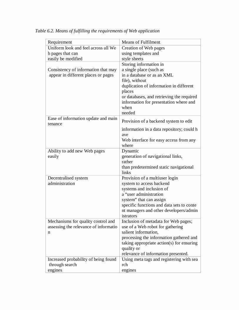
Table 6.2. Means of fulfilling the requirements of Web application
Requirement Means of Fulfilment Uniform look and feel across all Web pages that can
Creation of Web pages using templates and
easily be modified style sheets
Consistency of information that may appear in different places or pages
Storing information in a single place (such as in a database or as an XML file), without
duplication of information in different places
or databases, and retrieving the required information for presentation where and
when needed Ease of information update and maintenance Provision of a backend system to edit
information in a data repository; could have
Web interface for easy access from anywhere
Ability to add new Web pages easily
Dynamic generation of navigational links,
rather than predetermined static navigational
links Decentralised system administration
Provision of a multiuser login system to access backend systems and inclusion of a “user administration system” that can assign specific functions and data sets to content managers and other developers/administrators
Mechanisms for quality control and assessing the relevance of information
Inclusion of metadata for Web pages; use of a Web robot for gathering salient information,
processing the information gathered and taking appropriate action(s) for ensuring quality or relevance of information presented.
Increased probability of being found through search
Using meta tags and registering with search
engines engines

•An overall system architecture describing how the network and the various servers (Web servers, application servers and database servers) interact; •An application architecture depicting various information modules and the func-tions they support; and •A software architecture identifying various software and database modules re-quired to implement the application architecture. Table 6.2 summarises the means of fulfilling some of the requirements of Webbased Applications.We then decide on an appropriate development process model and develop a project plan. To successfully manage Web development, a sound project plan and a realistic schedule are necessary. Progress of development activities must be monitored and managed. Project planning and scheduling techniques that are commonly used in other disciplines can be used for Web development.
Following this,the various components of the system and web pages are designed, developed and tested.
Figure 6.2. Web page design
6.5.1 Web Page Design
Web page design is an important activity; it determines what information is presented and how it is presented to the users. A prototype usually contains a set of sample pages to evaluate the page layout, presentation, and navigation. Based on the feedback from the stakeholders, the page design is suitably modified. This process may go through a few iterations until the stakeholders and designers are satisfied with the page layout, presentation and the navigation structure.

Web page content development needs to take into consideration the stakeholders’ requirements, users’ cognitive abilities , technical issues and considerations, non technical issues, earlier experiences of developers and users, and lessons learned from similar Web applications in Figure 6.2.
If the Web system is intended for global use, by users from different countries, theweb content and presentation may have to be localised; there also may be a need for multilingual Web sites. Also, the Web site’s content and usability have to be designed from a global perspective and be responsive to cultural sensitivity in language along with appropriate use of colour, presentation, and animation . 6.6 Web Maintenance After a webbased system is developed and deployed online for use, it needs to be maintained. As outlined earlier, content maintenance is a continual process. We need to formulate content maintenance policies and procedures, based on the decision taken at the system architecture design stage on how the information content would be maintained, and then we need to implement them. Further, as the requirements of Web systems grow . It is important to periodically review Web based systems and applications regarding the currency of information content, potential security risks, performance of the system, and usage patterns , and take suitable measures to fix the shortcomings and weaknesses, if any. 6.7 Project Management
The purpose of project management is to ensure that all the key processes and activities work in harmony. Building successful web based applications requires close coordination among various efforts involved in the web development cycle. Many studies however, reveal that poor project management is the major cause of web failures both during development and subsequently in the operational phase. Poor project manage-ment will defeat good engineering; good project management is a recipe for success. Successfully managing a large, complex web development is a challenging task requiring multidisciplinary skills and is, in some ways, different from managing traditional IT projects.
Quality control, assurance and documentation are other important activities, but they are often neglected. Like project management, these activities need to spread throughout the web development lifecycle. 6.7.1 Steps to Successful Development
Successful development of Web systems and applications involves multiple interactive steps which influence one another. We recommend the following key steps for successful development and deployment of Web applications
1.Understand the system’s overall function and operational environment, including the business objectives and requirements, organisation culture and information management policy. 2.Clearly identify the stakeholders — that is, the system’s main users and their typical profiles, the organisation that needs the system, and who funds the development. 3.Elicit or specify the functional, technical, and nontechnical requirements of the stakeholders and the overall system. Further, recognise that these require-ments may not remain the same; rather, they are bound to evolve over time during the system development. 4.Develop overall system architecture of the Webbased system that meets the technical and nontechnical requirements. 5.Identify subprojects or subprocesses to implement the system architecture. If the subprojects are too complex to manage, further divide them until they become a set of manageable tasks. 6.Develop and implement the subprojects. 7.Incorporate effective mechanisms to manage the Web system’s evolution, change, and maintenance. As the system evolves, repeat the overall process or some parts of it, as required. 8.Address the nontechnical issues, such as revised business processes, organisa-tional and management policies, human resources development, and legal, cultural, and social aspects. 9.Measure the system’s performance, analyse the usage of the Web application from Web logs, and review and address users’ feedback and suggestions. 10.Refine and update the system.
6.8 Let Us Sum-up
In this context, we have discussed the evolution and process of engineering, web based design in the software companies, steps to involve the design development also.
6.9 Lesson End Activities 1. What is web based design? Why it is important in the software development? 2. Illustrate the steps of successful development of web design?

6.10 Check your Progress In the section 6.4 and 6.7 provides the reference.
6.11 References
1.Roger S. Pressman, Software Engineering – A Practitioners Approach, Fifth Edition, McGraw –Hill, 2005. 2. Ian Sommerville, Software Engineering, Sixth Edition, Perason Education, 2001.

LESSON – 7
WEB SYSTEM DESIGN Contents 7.0 Aims and Objectives 7.1 Introduction 7.2 Web Testing and Evaluation 7.3 Knowledge and Skills for Web Development
7.3.1 Web Development Team 7.3.2 General views of web engineering
7.4 WebE Project Management Guidelines 7.4.1 WebE Software Configuration Management Issues
7.5 Let Us Sum Up 7.6 Lesson end Activities 7.7 Check your Progress 7.8 References 7.0 Aims and Objectives In this lesson aims to explore that the web based design with challenges, checking the functionalities of web based system, knowledge and specific skills to use and views of web engineering. 7.1 Introduction The Internet is an open platform that provides unparalleled opportunities. But it has virtually no control over visitor volume, or when and how they access a Web system. This makes developing Web applications that exhibit satisfactory performance even under a sudden surge in number of users a nebulous and challenging task. Satisfying the expectations and needs of different types of users with varying skills is not easy. When users find a site unfriendly, confusing, or presented with too much information, they will leave frustrated. Worse yet, these frustrated users may spread the bad news to many others. Web site usability factors include good use of colours, information content, easy navigation, and many more. They also include evaluation from an international perspective so that you can reach a global audience. Web usability factors that impact the Web user experience are : page layout, design consistency, accessibility, information content, navigation, personalisation, performance, security, reliability and design standards. A Webbased system also has to satisfy many different stakeholders besides the diverse range of users, including: persons who maintain the system, the organisation that needs the system, and those who fund the system development. These may pose some additional challenges to Webbased system design and development.

Today’s Websavvy consumers do not tolerate much margin of error or failure. Web system slow down, failure, or security breach may cause a loss of its customers — probably permanently. A whopping 58 percent of first time customers would not return to a site that crashed . According to a study, US$4.35 billion may be lost in ebusiness due to poor Web download speeds alone.
As Web applications are becoming mission critical, there is greater demand for improved reliability, performance, and security of these applications. Poor design and infrastructure have caused many Web applications to be unable to support the demands placed on them, so they have therefore failed. Many Web sites have suffered site crashes, performance failures, security breaches, and outages — resulting in irate customers, lost revenue, devalued stocks, a tarnished reputation, permanent loss of customers, and law suits. Stock prices have become inextricably linked to the reliability of a company’s ecommerce site.
The recent major failures and their impact on enterprises have served as a forceful reminder of the need for capacity planning, and improved performance, quality, and reliability. Successful Web application deployment demands consistent Web site availability, a better understanding of its performance, scalability, and load balancing. Proactive measures are needed to prevent grinding halts and failures from happening in the first place.
Large scale Web system design is a complex and a challenging activity as it needs to consider many different aspects and requirements, some of which may have conflicting needs.
We use terms like scalability, reliability, availability, maintainability, usability and security to describe how well the system meets current and future needs and service level expectations. These utilities characterize web systems architectural and other qualities. In the face of increasingly complex systems, these system qualities are often more daunting to understand and manage.
Scalability refers to how well a system’s architecture can grow, as traffic, demand forservices, or resource utilisation grows. As Web sites grow, small software weaknesses that had no initial noticeable effects can lead to failures, reliability problems, usability problems, and security breaches. Developing Web applications that scale well represents one of today’s most important development challenges.
Flexibility is the extent to which the solution can adapt as business requirements change. A flexible architecture facilitates greater reusability and quicker deployment. Thus, the challenge is to design and develop sustainable Web systems for better: • Usability — interface design, navigation , • Comprehension, • Performance — responsiveness, • Security and integrity,

• Evolution, growth, and maintainability, and • Testability.
7.2 Web Testing and Evaluation
Testing plays a crucial role in the overall development process. However, more often than not, testing and evaluation are neglected aspects of Web development. Many developers test the system only after it had met with failures or limitations have become apparent, resorting to what is known as retroactive testing. What is desired in the first place is proactive testing at various stages of the Web development lifecycle. Benefits of proactive testing include assurance of proper functioning and guaranteed performance levels, avoidance of costly retroactive fixes, optimal performance, and lower risk.
Testing and validating a large complex Web system is a difficult and expensive
task. Testing should not be seen as a one off activity carried out near the end of development process. One needs to take a broad view and follow a more holistic approach to testing from design all the way to deployment, maintenance, and continual refinement. The test planning needs to be carried out early in the project lifecycle. A test plan provides a roadmap so that the Web site can be evaluated through requirements or design stage. It also helps to estimate the time and effort needed for testing — establishing a test environment, finding test personnel, writing test procedures before any testing can actually start, and testing and evaluating the system.
Lam groups Web testing into the following broad categories and provides excellent practical guidelines on how to test Web systems:
• Browser compatibility • Page display • Session management • Usability • Content analysis • Availability • Backup and recovery • Transactions • Shopping, order processing • Internalisation • Operational business procedures • System integration • Performance • Login and security
Experience shows that there are many common pitfalls in web testing and attempt
s should be made overcome them. Testing and evaluation of a Web application may be expensive, but the impact of failures resulting from lack of testing could be more costly or even disastrous.

7.3 Knowledge and Skills for Web Development
The knowledge and skills needed for large, complex web application development are quite diverse and span many different disciplines. They can be broadly classified as:
• Technologies supporting and facilitating Web applications • Design methods • Design for usability — interface design, navigation • Design for comprehension • Design for performance — responsiveness • Design for security and integrity • Design for evolution, growth and maintainability • Design for testability • Graphics and multimedia design • Web page development • System architecture • Web development methods and processes • Web project management • Development tools • Content management • Web standards and regulatory requirements
7.3.1 Web Development Team
As previously mentioned, development of a Web application requires a team of people with diverse skills and backgrounds. These individuals include programmers, graphic designers, Web page designers, usability experts, content developers, database designers and administrators, data communication and networking experts, and Web server administrators. A Web development team is multidisciplinary, like a film production team, and must be more versatile than a traditional software development team.
Hansen et al. (2001) presents a classification of the participants in a Web development team and a hierarchy for their skills and knowledge. This classification helps in forming a team and in devising a strategy for successful skill of the development team. 7.3.2 General views of web engineering
Web engineering is specifically targeted toward the successful development, deployment and maintenance of large, complex web based systems. It advocates a holistic and proactive approach to developing successful web applications. As more applications migrate to the Web environment and play increasingly significant roles in business, education, healthcare, government, and many day to day operations, the need for a Web engineering approach to Web application development will only increase. Further, as we now place greater emphasis on the performance, correctness, and
availability of web based systems, the development and maintenance process will assume greater significance. Web Engineering is an emerging discipline having both theoretical and practical significance. It is gaining the interest among researchers, developers, academics, and clients. This is evidenced by increased research activities and publications in this area, hosting of dedicated international conferences and workshops, publication of new journals devoted to Web Engineering, and universities offering special courses and programmes on the subject. It is destined for further advancement through research, education, and practice.
To advance Web engineering, it is essential to define its core body of knowledge, to identify the areas in need of greater research and to develop a strategy to tackle the new technologies, new applications and the various technical, methodological, and societal issues that arise in tandem with such developments. Some of the areas that need further study, in no particular order, include:
Web application delivery on multiple devices — desktop and pocket PCs, mobile phones, PDAs, TVs and refrigerators
Contextaware Web applications and contextsensitive responses Deviceindependent Web access and content presentation Modelling and simulation of Web applications and systems Performance evolution and enhancement Testing and validation of systems Effort and cost estimation Web personalisation Quality control and assurance
Web Engineering will not make the problems and the risks go away. But, it can
help you plan, monitor, control, and cope with the challenging task of developing large, complex Web applications. It will also facilitate making more informed decisions and developing better quality and better engineered Web systems and applications. It is important to understand the wider context in which a Web based system or application will be used, and design an architecture that will support the development, operation, and maintenance as well as evolution of the Web application in that context, addressing the key issues and considerations. We strongly recommend that Web developers and project managers move away from an ad hoc, hacker type approach to a well planned, systematic, and documented approach for the development of large, high-performance, evolutionary, and/or mission critical Web sites and applications. Our key recommendations for successfully developing and implementing large, complex Web application are to:
• Adopt a sound strategy and follow a suitable methodology to successfully manage the development and maintenance of Web systems.
• Recognise that, in most cases, development of a Web application is not an event, but a process, since the applications’ requirements evolve. It will have a start, but it will not have a predictable end as in traditional IT/software projects.
• Within the continuous process, identify, plan, and schedule various development activities so that they have a defined start and finish.
• Remember that the planning and scheduling of activities is very important to successfully manage the overall development, allocate resources, and monitor progress.
• Consider the big picture during context analysis, planning, and designing a Web application. If you do not, you may end up redesigning the entire system and repeating the process all over again. If you address the changing nature of requirements early on, you can build into the design cost effective ways of managing change and new requirements.
• Recognise that development of a large Web application calls for teamwork and shared responsibility among the team members, so motivate a team culture.
Web engineering has been successfully applied in a number of Web applications. A well engineered Web system is:
• Functionally complete and correct • Usable • Robust and reliable • Maintainable • Secure • Perform satisfactorily even under flash and peak loads • Scalable • Portable, where required perform across different common platforms; compatible
with multiple browsers • Reusable • Interoperable with other Web and information systems • Universal accessibility (access by people with different kinds disabilities) • Well documented
Time to deploy an online Web system, though still important, is no longer a dominant process driver, as more emphasis is now placed on quality Web systems in terms of functionally, usability, content maintainability, performance, and reliability. Web engineering can help enterprises and developers to convert their Web systems and applications from a potential costly mess into powerful resource for gaining sustainable competitive advantage. 7. 4 WebE Project Management Guidelines
Initiating a project many of the analysis activities should be performed internally a rough design for the WebApp should be developed internally a rough delivery schedule

including milestone dates and final delivery dates should be developed the degree of oversight and interaction by the contractor with the vendor should be identified Selection of candidate outsourcing vendors Interview past clients to determine vendor's past performance be certain the vendor's chief web engineer(s) from past successful projects will involved with yours carefully examine samples of the vendor's work on projects similar to yours Assessing the validity of price quotes and reliability estimates does the quoted cost of the WebApp provide a direct or indirect return-on-investment that justifies the project? does the vendor exhibit the required level of professionalism and experience? Degree of project management you can expect or perform Assessing the development schedule Managing the scope 7.4.1 WebE Software Configuration Management Issues
Content integrating heterogeneous media volatility People designers often are forced to create content content creators often have no software engineering knowledge Scalability Politics
7.5 Let Us Sum-up
Web based design is one of the important and enhanced version of software development. Therefore we discussed the challenges of web system design, general views of usage and development with guidelines of web engineering.
7.6 Lesson End Activities
1. Who owns a WebApp? 2. Who assumes responsibility for accuracy? 3. Who makes changes? 4. Who pays for changes?
7.7 Check your Progress In the earlier sections that have discussed the respective activities. Compare your assignments.

7.8 References 1.Roger S. Pressman, Software Engineering – A Practitioners Approach, Fifth Edition, McGraw –Hill, 2005. 2. Ian Sommerville, Software Engineering, Sixth Edition, Perason Education, 2001.

LESSON – 8
PROJECT MANAGEMENT CONCEPTS Contents 8.0 Aims and Objectives 8.1 Introduction to Project Management
8.1.1 Management Spectrum 8.1.2 People 8.1.3 Software Team Organization
8.2 Software Project Planning 8.2.1 Project Planning Objectives
8.3 Let Us Sum Up 8.4 Lesson end Activities 8.5 Check your Progress 8.6 References 8.0 Aims and Objectives
Project management involves the planning, monitoring, and control of people,
process, and events that occur during software development. Everyone manages, but the scope of each person's management activities varies according his or her role in the project. Software needs to be managed because it is a complex undertaking with a long duration time. Managers must focus on the fours P's to be successful such as people, product, process, and project.
A project plan is a document that defines the four P's in such a way as to ensure a cost effective, high quality software product. The only way to be sure that a project plan worked correctly is by observing that a high quality product was delivered on time and under budget.
8.1 Introduction to Project Management
Project management is a methodical approach to planning and guiding project processes from start to finish. According to the Project Management Institute, the processes are guided through five stages: initiation, planning, executing, controlling, and closing. Project management can be applied to almost any type of project and is widely used to control the complex processes of software development projects.
The systems development life cycle (SDLC) is one example of a methodology for
guiding the project management process from an initial feasibility study through maintenance of the completed application. Various SDLC approaches include the waterfall model, which was the original SDLC method; rapid application development (RAD); joint application development (JAD); the fountain model; the spiral model; build

and fix; and synchronize-and-stabilize. A number of charting methods, such as the Gantt chart and PERT chart have been developed as tools to create a graphic representation of a project plan and its current status.
8.1.1 Management Spectrum
People (recruiting, selection, performance management, training, compensation, career development, organization, work design, team/culture development) Product (product objectives, scope, alternative solutions, constraint tradeoffs) Process (framework activities populated with tasks, milestones, work products, and QA points) Project (planning, monitoring, controlling) 8.1.2 People
Players (senior managers, technical managers, practitioners, customers, end-users) Team leadership model (motivation, organization, skills) Characteristics of effective project managers (problem solving, managerial identity, achievement, influence and team building) 8.1.3 Software Team Organization
Democratic decentralized (rotating task coordinators and group consensus) Controlled decentralized (permanent leader, group problem solving, subgroup implementation of solutions) Controlled centralized (top level problem solving and internal coordination managed by team leader)
Factors Affecting Team Organization Difficulty of problem to be solved Size of resulting program Team lifetime Degree to which problem can be modularized Required quality and reliability of the system to be built Rigidity of the delivery date Degree of communication required for the project Coordination and Communication Issues Formal, impersonal approaches (e.g. documents, milestones, memos) Formal interpersonal approaches (e.g. review meetings, inspections) Informal interpersonal approaches (e.g. information meetings, problem
solving) Electronic communication (e.g. e-mail, bulletin boards, video
conferencing) Interpersonal network (e.g. informal discussion with people other than
project team members)

8.2 Software Project Planning
Software planning involves estimating how much time, effort, money, and resources will be required to build a specific software system. After the project scope is determined and the problem is decomposed into smaller problems, software managers use historical project data to determine estimates for each. The final estimates are typically adjusted by taking project complexity and risk into account. The resulting work product is called a project management plan.
Estimation Reliability Factors Project complexity Project size Degree of structural uncertainty (degree to which requirements have
solidified, the ease with which functions can be compartmentalized, and the hierarchical nature of the information processed)
Availability of historical information 8.2.1 Project Planning Objectives
To provide a framework that enables software manager to make a reasonable estimate of resources, cost, and schedule. Project outcomes should be bounded by 'best case' and 'worst case' scenarios. Estimates should be updated as the project progresses. Software Scope Describes the data to be processed and produced, control parameters, function, performance, constraints, external interfaces, and reliability. Often functions described in the software scope statement are refined to allow for better estimates of cost and schedule. Customer Communication and Scope Determine the customer's overall goals for the proposed system and any expected benefits. Determine the customer's perceptions concerning the nature if a good solution to the problem. Evaluate the effectiveness of the customer meeting. Feasibility Technical feasibility is not a good enough reason to build a product. The product must meet the customer's needs and not be available as an off-the-shelf purchase.

Estimation of Resources Human Resources - number of people required and skills needed to complete the development project Reusable Software Resources - off-the-shelf components, full-experience components, partial-experience components, new components Development Environment - hardware and software required to be accessible by software team during the development process Software Project Estimation Options Delay estimation until late in the project. Base estimates on similar projects already completed. Use simple decomposition techniques to estimate project cost and effort. Use empirical models for software cost and effort estimation. Automated tools may assist with project decomposition and estimation. Automated Estimation Tool Capabilities
Sizing of project deliverables Selecting project activities Predicting staffing levels Predicting software effort Predicting software cost Predicting software schedule
8.3 Let Us Sum-up Software engineers deals with the people like customer, team of software development during the development of software project. In this lesson we have collected the information about planning techniques, monitoring, controlling and development.
8.4 Lesson End Activities 1. Write the responsibilities of software team in any organization?
8.5 Check your Progress
1. Discuss about software project planning
8.6 References
1.Roger S. Pressman, Software Engineering – A Practitioners Approach, Fifth Edition, McGraw –Hill, 2005. 2. Ian Sommerville, Software Engineering, Sixth Edition, Perason Education, 2001.

LESSON – 9
PROJECT SCHEDULING AND TRACKING Contents 9.0 Aims and Objectives 9.1 Introduction – Basic Concepts 9.2 Basic Principles 9.3 The Relationship between People and Effort 9.3.1 An Example 9.3.2 An Empirical Relationship 9.4 Effort Distribution 9.5 Defining a task for the Software Project 9.5.1 Degree of Rigor 9.5.2 Defining Adaptation Criteria 9.6 Let Us Sum Up 9.7 Lesson end Activities 9.8 Check your Progress 9.9 References 9.0 Aims and Objectives
The project may be small or large every software engineer must follow the scheduling and proper tracking of the progress. To create a network of software engineering tasks that will enable to get the job done on time. Once the network is created, then should assign responsibility for each task, make sure it gets done, and adapt the network as risks become reality. In a nutshell, that’s software project scheduling and tracking. At the project level, software project managers using information solicited from software engineers. At an individual level, software engineers themselves.
In order to build a complex system, many software engineering tasks occur in
parallel, and the result of work performed during one task may have a profound effect on work to be conducted in another task. These interdependencies are very difficult to understand without a schedule. lt’s also virtually impossible to assess progress on a moderate or large software project without a detailed schedule. The software engineering tasks dictated by the software process model are refined for the functionality to be built. 9.1 Introduction - Basic Concepts
Although there are many reasons why software is delivered late, most can be traced to one or more of the following root causes: An unrealistic deadline established by someone outside the software development
group and forced on managers and practitioner's within the group.

Changing customer requirements that are not reflected in schedule changes.
An honest underestimate of the amount of effort and/or the number of
resources that will be required to do the job. Predictable and/or unpredictable risks that were not considered when the
project commenced. Technical difficulties that could not have been foreseen in advance.
Human difficulties that could not have been foreseen in advance.
Miscommunication among project staff that results in delays.
A failure by project management to recognize that the project is falling behind
schedule and a lack of action to correct the problem.
Aggressive deadlines are a fact of life in the software business. Sometimes such deadlines are demanded for reasons that are legitimate, from the created in a manner that enables the software team to meet the delivery deadline established. The project schedule and related information are produced. Proper scheduling requires that
(1) all tasks appear in the network, (2) effort and timing are intelligently allocated to each task, (3) interdependencies between tasks are properly indicated, (4) resources are allocated for the work to be done, and (5) closely spaced milestones are provided so that progress can be tracked.
QUICK 9.2 Basic Principles
The project manager’s objective is to define all project tasks, build a network that depicts their interdependencies, identify the tasks that are critical within the network, and then track their progress to ensure that delay is recognized "one day at a time."
To accomplish this, the manager must have a schedule that has been defined at a degree of resolution that enables the manager to monitor progress and control the project. Software project scheduling is an activity that distributes estimated effort across the planned project duration by allocating the effort to specific software engineering tasks.
You might also add that adding more people does not reduce calendar time proportionally. It is important to note, however, that the schedule evolves over time.

During early stages of project planning, a macroscopic schedule is developed. This type of schedule identifies all major software engineering activities and the product functions to which they are applied. As the project gets under way, each entry on the macroscopic schedule is refined into a detailed schedule. Here, specific software tasks are identified and scheduled.
Scheduling for software engineering projects can be viewed from two rather different perspectives. In the first, an end-date for release of a computer-based system has already been established. The software organization is constrained to distribute effort within the prescribed time frame. The second view of software scheduling assumes that rough chronological bounds have been discussed but that the end-date is set by the software engineering organization. Effort is distributed to make best use of resources and an end-date is defined after careful analysis of the software. Unfortunately, the first situation is encountered far more frequently than the second. Like all other areas of software engineering, a number of basic principles guide software project scheduling: Compartmentalization. The project must be compartmentalized into a number of manageable activities and tasks. To accomplish compartmentalization, both the product and the process are decomposed. Interdependency. The interdependency of each compartmentalized activity or task must be determined. Some tasks must occur in sequence while others can occur in parallel. Some activities cannot commence until the work product produced by another is available. Other activities can occur independently. Time allocation. Each task to be scheduled must be allocated some number of work units. In addition, each task must be assigned a start date and a completion date that are a function of the interdependencies and whether work will be conducted on a full-time or part-time basis. Effort validation. Every project has a defined number of staff members. As time allocation occurs, the project manager must ensure that no more than the allocated number of people have been scheduled at any given time. For example, consider a project that has three assigned staff members. On a given day, seven concurrent tasks must be accomplished. Each task requires 0.50 person days of effort. More effort has been allocated than there are people to do the work. Defined responsibilities. Every task that is scheduled should be assigned to a specific team member. Defined outcomes. Every task that is scheduled should have a defined outcome. For software projects, the outcome is normally a work product or a part of a work product. Work products are often combined in deliverables.

Defined milestones. Every task or group of tasks should be associated with a project milestone. A milestone is accomplished when one or more work products has been reviewed for quality and has been approved. Each of these principles is applied as the project schedule evolves. 9.3 The Relationship between People and Effort
In a small software development project a single person can analyze requirements, perform design, generate code, and conduct tests. As the size of a project increases, more people must become involved. There is a common myth that is still believed by many managers who are responsible for software development effort: "If we fall behind schedule, we can always add more programmers and catch up later in the project." Unfortunately, adding people late in a project often has a disruptive effect on the project, causing schedules to slip even further. The people who are added must learn the system, and the people who teach them are the same people who were doing the work. While teaching, no work is done, and the project falls further behind.
In addition to the time it takes to learn the system, more people increase the number of communication paths and the complexity of communication throughout a project. Although communication is absolutely essential to successful software development, every new communication path requires additional effort and therefore additional time. 9.3.1 An Example
Consider four software engineers, each capable of producing 5000 LOC/year when working on an individual project. When these four engineers are placed on a team project, six potential communication paths are possible. Each communication path requires time that could otherwise be spent developing software. We shall assume that team productivity will be reduced by 250 LOC/year for each communication path, due to the overhead associated with communication. Therefore, team productivity is 20,000 _ (250 x 6) = 18,500 LOC/year—7.5 percent less than what we might expect. It is possible to pose a counterargument: Communication, if it is effective, can enhance the quality of the work being performed, thereby reducing the amount of rework and increasing the individual productivity of team members. The one-year project on which the team is working falls behind schedule, and with two months remaining, two additional people are added to the team. The number of communication paths escalates to 14. The productivity input of the new staff is the equivalent of 840 x 2 = 1680 LOC for the two months remaining before delivery. Team productivity now is 20,000 + 1680 _ (250 x 14) = 18,180 LOC/year.

Although the example is a gross oversimplification of real-world circumstances, it does illustrate another key point: The relationship between the number of people working on a software project and overall productivity is not linear.
Based on the people/work relationship, are teams counterproductive? The answer is an emphatic "no," if communication improves software quality. In fact, formal technical reviews conducted by software teams can lead to better analysis and design, and more important, can reduce the number of errors that go undetected until testing. Hence, productivity and quality, when measured by time to project completion and customer satisfaction, can actually improve. 9.3.2. An Empirical Relationship
Recalling the software equation that was introduced, we can demonstrate the highly nonlinear relationship between chronological time to complete a project and human effort applied to the project. The number of delivered lines of code L, is related to effort and development time by the equation: L = P x E1/3t4/3 where E is development effort in person-months, P is a productivity parameter that reflects a variety of factors that lead to high-quality software engineering work (typical values for P range between 2,000 and 12,000), and t is the project duration in calendar months. Rearranging this software equation, we can arrive at an expression for development effort E: E = L3/( P3t4 ) (7-1) where E is the effort expended (in person-years) over the entire life cycle for software development and maintenance and t is the development time in years. The equation for development effort can be related to development cost by the inclusion of a burdened labor rate factor ($/person-year). This leads to some interesting results. Consider a complex, real-time software project estimated at 33,000 LOC, 12 person-years of effort. If eight people are assigned to the project team, the project can be completed in approximately 1.3 years. If, however, we extend the end-date to 1.75 years, the highly nonlinear nature of the model described in Equation (7-1) yields: E = L3/( P3t4 ) ~ 3.8 person-years. The relationship between the number of people working on a software project and overall productivity is not linear.

This implies that, by extending the end-date six months, we can reduce the number of people from eight to four! The validity of such results is open to debate, but the implication is clear: Benefit can be gained by using fewer people over a somewhat longer time span to accomplish the same objective. 9.4 Effort Distribution
Each of the software project estimation techniques discussed in the early stage which leads to estimates of work units (e.g., person-months) required to complete software development. A recommended distribution of effort across the definition and development phases is often referred to as the 40–20–40 rule. Forty percent of all effort is allocated to front-end analysis and design. A similar percentage is applied to back-end testing. You can correctly infer that coding (20 percent of effort) is de-emphasized.
This effort distribution should be used as a guideline only. The characteristics of
each project must dictate the distribution of effort. Work expended on project planning rarely accounts for more than 2–3 percent of effort, unless the plan commits an organization to large expenditures with high risk. Requirements analysis may comprise 10–25 percent of project effort. Effort expended on analysis or prototyping should increase in direct proportion with project size and complexity. A range of 20 to 25 percent of effort is normally applied to software design. Time expended for design review and subsequent iteration must also be considered.
Because of the effort applied to software design, code should follow with relatively little difficulty. A range of 15–20 percent of overall effort can be achieved. Testing and subsequent debugging can account for 30–40 percent of software development effort. The criticality of the software often dictates the amount of testing that is required. If software is human rated (i.e., software failure can result in loss of life), even higher percentages are typical. 9.5 Defining a Task Set for the Software Project
A number of different process models were described in Lesson 2. These models offer different paradigms for software development. Regardless of whether a software team chooses a linear sequential paradigm, an iterative paradigm, an evolutionary paradigm, a concurrent paradigm or some permutation, the process model is populated by a set of tasks that enable a software team to define, develop, and ultimately support computer software.
There is no single set of tasks is appropriate for all projects. The set of tasks that would be appropriate for a large, complex system would likely be perceived as overkill for a small, relatively simple software product. Therefore, an effective software process should define a collection of task sets, each designed to meet the needs of different types of projects.

A task set is a collection of software engineering work tasks, milestones, and deliverables that must be accomplished to complete a particular project. The task set to be chosen must provide enough discipline to achieve high software quality. But, at the same time, it must not burden the project team with unnecessary work. Task sets are designed to accommodate different types of projects and different degrees of rigor. Although it is difficult to develop a comprehensive taxonomy of software project types, most software organizations encounter the following projects: 1. Concept development projects that are initiated to explore some new business concept or application of some new technology. 2. New application development projects that are undertaken as a consequence of a specific customer request. 3. Application enhancement projects that occur when existing software undergoes major modifications to function, performance, or interfaces that are observable by the end-user. 4. Application maintenance projects that correct, adapt, or extend existing software in ways that may not be immediately obvious to the end-user. 5. Reengineering projects that are undertaken with the intent of rebuilding an existing (legacy) system in whole or in part.
Even within a single project type, many factors influence the task set to be chosen. When taken in combination, these factors provide an indication of the degree of rigor with which the software process should be applied. 9.5.1 Degree of Rigor
Even for a project of a particular type, the degree of rigor with which the software process is applied may vary significantly. The degree of rigor is a function of many project characteristics. As an example, small, non-business-critical projects can generally be addressed with somewhat less rigor than large, complex business-critical applications. It should be noted, however, that all projects must be conducted in a manner that results in timely, high-quality deliverables. Four different degrees of rigor can be defined: Casual. All process framework activities are applied, but only a minimum task set is required. In general, umbrella tasks will be minimized and documentation requirements will be reduced. All basic principles of software engineering are still applicable. Structured. The process framework will be applied for this project. Framework activities and related tasks appropriate to the project type will be applied and umbrella activities necessary to ensure the high quality of the project.

Strict. The full process will be applied for this project with a degree of discipline that will ensure high quality. All umbrella activities will be applied and robust work products will be produced. Quick reaction. The process framework will be applied for this project, but because of an emergency situation only those tasks essential to maintaining good quality will be applied. “Back-filling” (i.e., developing a complete set of documentation, conducting additional reviews) will be accomplished after the application/product is delivered to the customer. The project manager must develop a systematic approach for selecting the degree of rigor that is appropriate for a particular project. To accomplish this, project adaptation criteria are defined and a task set selector value is computed. 9.5.2 Defining Adaptation Criteria Adaptation criteria are used to determine the recommended degree of rigor with which the software process should be applied on a project. Eleven adaptation criteria are defined for software projects:
• Size of the project • Number of potential users • Mission criticality • Application longevity • Stability of requirements • Ease of customer/developer communication • Maturity of applicable technology • Performance constraints • Embedded and non embedded characteristics • Project staff • Reengineering factors
Each of the adaptation criteria is assigned a grade that ranges between 1 and 5,
where 1 represents a project in which a small subset of process tasks are required and overall methodological and documentation requirements are minimal, and 5 represents a project in which a complete set of process tasks should be applied and overall methodological and documentation requirements are substantial.
Emergency situations should be rare. An emergency is not the same as a project with tight time constraints. 9.6 Let Us Sum-up
In order to construct a complex or simple system in the software development, it has break into levels or layers. Before the system begins at any kind of work, the

better scheduling is essential to precede the activities and then it may be easy to track all sorts of process in the software development.
9.7 Lesson End Activities 1. Classify the basic principles of project scheduling? 2. Define the various kinds of degree of rigor in the software process? 3. Provide the better example of relationship between people and effort?
9.8 Check your Progress
We can refer the previous sections 9.2 and 9.3.
9.9 References
1.Roger S. Pressman, Software Engineering – A Practitioners Approach, Fifth Edition, McGraw –Hill, 2005. 2. Ian Sommerville, Software Engineering, Sixth Edition, Perason Education, 2001.

LESSON – 10
DEFINING TASK SETS Contents 10.0 Aims and Objectives 10.1 Computing a Task Set Selector Value
10.1.1 Interpreting the TSS Value and selecting the Task set 10.2 Selecting Software Engineering Tasks 10.3 Refinement of Major Tasks 10.4 Defining a Task Network 10.5 Project Scheduling 10.6 Let Us Sum Up 10.7 Lesson end Activities 10.8 Check your Progress 10.9 References 10.0 Aims and Objectives At the end of this lesson, you should be able to understand about software engineering tasks. 10.1 Computing a Task Set Selector Value To select the appropriate task set for a project, the following steps should be conducted: 1. Review each of the adaptation criteria in previous section and assign the appropriate grades (1 to 5) based on the characteristics of the project. These grades should be entered into Table 10.1. 2. Review the weighting factors assigned to each of the criteria. The value of a weighting factor ranges from 0.8 to 1.2 and provides an indication of the relative importance of a particular adaptation criterion to the types of software developed within the local environment. If modifications are required to better reflect local circumstances, they should be made. 3. Multiply the grade entered in Table 10.1 by the weighting factor and by the entry point multiplier for the type of project to be undertaken. The entry point multiplier takes on a value of 0 or 1 and indicates the relevance of the adaptation criterion to the project type. The result of the product grade x weighting factor x entry point multiplier is placed in the Product column of Table 10.1 for each adaptation criteria individually. 4. Compute the average of all entries in the Product column and place the result in the space marked task set selector (TSS). This value will be used to help select the task set that is most appropriate for the project.

TABLE 10.1 COMPUTING THE TASK SET SELECTOR Adaptation Criteria
Grade Weight
Conc. NDev. Enhan. Maint. Reeng.
Product
Size of project Number of users Business criticality Longevity
- - - -
1.20 1.10 1.10 0.90 1.20
0 0 0 0 0
1 1 1 1 1
1 1 1 1 1
1 1 1 0 1
1 1 1 0 1
- - - - -
Task set selector (TSS) 10.1.1 Interpreting the TSS Value and Selecting the Task Set
Once the task set selector is computed, the following guidelines can be used to select the appropriate task set for a project:
Task set selector value Degree of rigor TSS < 1.2 casual 1.0 < TSS < 3.0 structured TSS > 2.4 strict
The overlap in TSS values from one recommended task set to another is purposeful and is intended to illustrate that sharp boundaries are impossible to define when making task set selections. In the final analysis, the task set selector value, past experience, and common sense must all be factored into the choice of the task set for a project. Table 10.2 illustrates how TSS might be computed for a hypothetical project. The project manager selects the grades shown in the Grade column. The project type is new application development. Therefore, entry point multipliers are selected from the NDev column. The entry in the Product column is computed using Grade x Weight x NewDev entry point multiplier The value of TSS (computed as the average of all entries in the product column) is 2.8. Using the criteria discussed previously, the manager has the

option of using either the structured or the strict task set. The final decision is made once all project factors have been considered. TABLE 10.2 COMPUTING THE TASK SET SELECTOR—AN EXAMPLE Adaptation Criteria
Grade Weight
Conc. NDev. Enhan. Maint. Reeng.
Product
Size of project Number of users Business criticality Longevity
2 3 4 3
1.20 1.10 1.10 0.90
0 0 0 0
1 1 1 1
1 1 1 1
1 1 1 0
1 1 1 0
2.4 3.3 4.4 2.7
Task set selector (TSS) 3.2 10.2 SELECTING SOFTWARE ENGINEERING TASKS
In order to develop a project schedule, a task set must be distributed on the project time line. As we noted in earlier section, the task set will vary depending upon the project type and the degree of rigor. Each of the project types described in earlier section may be approached using a process model that is linear sequential, iterative such as the prototyping or incremental models, or evolutionary as the spiral model. In some cases, one project type flows smoothly into the next. For example, concept development projects that succeed often evolve into new application development projects.
As a new application development project ends, an application enhancement project sometimes begins. This progression is both natural and predictable and will occur regardless of the process model that is adopted by an organization. Therefore, the major software engineering tasks described in the sections that follow are applicable to all process model flows. As an example, we consider the software engineering tasks for a concept development project. Concept development projects are initiated when the potential for some new technology must be explored. There is no certainty that the technology will be applicable, but a customer believes that potential benefit exists. Concept development projects are approached by applying the following major tasks:
Concept scoping determines the overall scope of the project. Preliminary concept planning establishes the organization’s ability to undertake the work implied by the project scope. Technology risk assessment evaluates the risk associated with the technology to be implemented as part of project scope. Proof of concept demonstrates the viability of a new technology in the software context. Concept implementation implements the concept representation in a manner that can be reviewed by a customer and is used for “marketing” purposes when a concept must be sold to other customers or management. Customer reaction to the concept solicits feedback on a new technology concept and targets specific customer applications. A quick scan of these tasks should yield few surprises. In fact, the software engineering flow for concept development projects is little more than common sense. The software team must understand what must be done; then the team must determine whether anyone is available to do it, consider the risks associated with the work, prove the technology in some way, and implement it in a prototypical manner so that the customer can evaluate it. Finally, if the concept is viable, a production version must be produced. It is important to note that concept development framework activities are iterative in nature. That is, an actual concept development project might approach these activities in a number of planned increments, each designed to produce a deliverable that can be evaluated by the customer. If a linear process model flow is chosen, each of these increments is defined in a repeating sequence as illustrated in Figure 10.1. During each sequence, umbrella activities are applied; quality is monitored; and at the end of each sequence, a deliverable is produced.

Figure 10.1 Concept development tasks in a linear sequential model With each iteration, the deliverable should converge toward the defined end product for the concept development stage. If an evolutionary model is chosen, the layout of tasks 1.1 through 1.6 would appear as shown in Figure 10.2.

Figure 10.2 Concept development tasks using on evolutionary model Major software engineering tasks for other project types can be defined and applied in a similar manner. 10.3 REFINEMENT OF MAJOR TASKS
The major tasks described in earlier section may be used to define a macroscopic schedule for a project. However, the macroscopic schedule must be refined to create a detailed project schedule. Refinement begins by taking each major task and decomposing it into a set of subtasks.
As an example of task decomposition, consider concept scoping for a development project discussed. Task refinement can be accomplished using an outline format, but in this book, a process design language approach is used to illustrate the flow of the concept scoping activity:

Task definition: Task I.1 Concept Scoping I.1.1 Identify need, benefits and potential customers; I.1.2 Define desired output/control and input events that drive the application;
Begin Task I.1.2 I.1.2.1 FTR: Review written description of need9 I.1.2.2 Derive a list of customer visible outputs/inputs
case of: mechanics mechanics = quality function deployment
meet with customer to isolate major concept requirements; interview end-users; observe current approach to problem, current process; review past requests and complaints;
mechanics = structured analysis make list of major data objects; define relationships between objects; define object attributes;
mechanics = object view make list of problem classes; develop class hierarchy and class connections; define attributes for classes;
endcase
I.1.2.3 FTR: Review outputs/inputs with customer and revise as required; endtask Task I.1.2 I.1.3 Define the functionality/behavior for each major function; Begin Task I.1.3 I.1.3.1 FTR: Review output and input data objects derived in task I.1.2; I.1.3.2 Derive a model of functions/behaviors;
case of: mechanics mechanics = quality function deployment
meet with customer to review major concept requirements; interview end-users; observe current approach to problem, current process; develop a hierarchical outline of functions/behaviors;
mechanics = structured analysis derive a context level data flow diagram; refine the data flow diagram to provide more detail; write processing narratives for functions at lowest level of r
efinement; mechanics = object view
define operations/methods that are relevant for each class; endcase

I.1.3.3 FTR: Review functions/behaviors with customer and revise as required; endtask Task I.1.3 I.1.4 Isolate those elements of the technology to be implemented in software; I.1.5 Research availability of existing software; I.1.6 Define technical feasibility; I.1.7 Make quick estimate of size; I.1.8 Create a Scope Definition; endTask definition: Task I.1 The tasks and subtasks noted in the process design language refinement form the basis for a detailed schedule for the concept scoping activity. 10.4 DEFINING A TASK NETWORK
Individual tasks and subtasks have interdependencies based on their sequence. In addition, when more than one person is involved in a software engineering project, it is likely that development activities and tasks will be performed in parallel. When this occurs, concurrent tasks must be coordinated so that they will be complete when later tasks require their work product(s). A task network, also called an activity network, is a graphic representation of the task flow for a project. It is sometimes used as the mechanism through which task sequence and dependencies are input to an automated project scheduling tool. In its simplest form, the task network depicts major software engineering tasks. Figure 10.3 shows a schematic task network for a concept development project.
Figure 10.3 A task network of concept development

The concurrent nature of software engineering activities leads to a number of important scheduling requirements. Because parallel tasks occur asynchronously, the planner must determine inter task dependencies to ensure continuous progress toward completion. In addition, the project manager should be aware of those tasks that lie on the critical path. That is, tasks that must be completed on schedule if the project as a whole is to be completed on schedule. These issues are discussed in more detail later in this Lesson.
It is important to note that the task network shown in Figure 10.3 is macroscopic. In a detailed task network, each activity shown in Figure 10.3 would be expanded. For example, Task I.1 would be expanded to show all tasks detailed in the refinement of Tasks I.1 shown. 10.5 PROJECT SCHEDULING
Scheduling of a software project does not differ greatly from scheduling of any
multitask engineering effort. Therefore, generalized project scheduling tools and techniques can be applied with little modification to software projects.
Program evaluation and review technique (PERT) and critical path method (CPM) are two project scheduling methods that can be applied to software development. Both techniques are driven by information already developed in earlier project planning activities: • Estimates of effort • A decomposition of the product function • The selection of the appropriate process model and task set • Decomposition of tasks Interdependencies among tasks may be defined using a task network. Tasks, sometimes called the project work breakdown structure (WBS), are defined for the product as a whole or for individual functions. Both PERT and CPM provide quantitative tools that allow the software planner to (1) determine the critical path—the chain of tasks that determines the duration of the project; (2) establish “most likely” time estimates for individual tasks by applying statistical models; and (3) calculate “boundary times” that define a time "window" for a particular task.

10.6 Let Us Sum-up In this lesson we have identified the concepts development with the help of task sets. Assigning the tasks are most significant to collect the grade of other activities in the work.
10.7 Lesson End Activities 1. How you can select a software engineering task? 2. Define a task network of the banking application?
10.8 Check your Progress Based on our software engineering task the task sets will vary. If you need more clarification take look of earlier sections in this lesson.
10.9 References
1.Roger S. Pressman, Software Engineering – A Practitioners Approach, Fifth Edition, McGraw –Hill, 2005. 2. Ian Sommerville, Software Engineering, Sixth Edition, Perason Education, 2001.

LESSON 11
RISK ANALYSIS AND MANAGEMENT Contents 11.0 Aims and Objectives 11.1 Introduction
11.1.1 Risk Example 11.1.2 Software Risk Evaluation
11.2 The Principles of Risk Management 11.3 The steps of managing risks 11.4 Potential Treatments of risk
11.4.1 Create a risk mitigation plan 11.4.2 Implementation 11.4.3 Review and evaluation of the plan 11.4.4 Risk management activities as applied to project management
11.5 Software Risks 11.3 Let Us Sum Up 11.4 Lesson end Activities 11.5 Check your Progress 11.6 References 11.0 Aims and Objectives
Risks are potential problems that might affect the successful completion of a software project. Risks involve uncertainty and potential losses. Risk analysis and management are intended to help a software team understand and manage uncertainty during the development process. The important thing is to remember that things can go wrong and to make plans to minimize their impact when they do. The work product is called a Risk Mitigation, Monitoring, and Management Plan (RMMM). 11.1 Introduction The term risk management is applied in a number of diverse disciplines. People in the fields of statistics, economics, psychology, social sciences, biology, engineering, toxicology, systems analysis, operations research, and decision theory, to name a few, have been addressing the field of risk management. Kloman summarized the meaning of risk management in the context of a number of different disciplines in an article for Risk Analysis: "What is risk management? To many social analysts, politicians, and academics it is the management of environmental and nuclear risks, those technology-generated macro-risks that appear to threaten our existence. To bankers and financial officers it is the

sophisticated use of such techniques as currency hedging and interest rate swaps. To insurance buyers and sellers it is coordination of insurable risks and the reduction of insurance costs. To hospital administrators it may mean 'quality assurance.' To safety professionals it is reducing accidents and injuries." 11.1.1 Risk Example A company has introduced object-oriented (OO) technology into its organization by selecting a well-defined project "X" with hard schedule constraints to pilot the use of the technology. Although many "X" project personnel were familiar with the OO concept, it had not been part of their development process, and they have had very little experience and training in the technology's application. It is taking project personnel longer than expected to climb the learning curve. Some personnel are concerned, for example, that the modules implemented to date might be too inefficient to satisfy project "X" performance requirements. The risk is: Given the lack of OO technology experience and training, there is a possibility that the product will not meet performance or functionality requirements within the defined schedule. Non-Risk Example Another company is developing a flight control system. During system integration testing the flight control system becomes unstable because processing of the control function is not quick enough during a specific maneuver sequence. The instability of the system is not a risk since the event is a certainty - it is a problem.
Continuous Risk Management Example
When using Continuous Risk Management, risks are assessed continuously and used for decision-making in all phases of a project. Risks are carried forward and dealt with until they are resolved or they turn into problems and are handled as such.
Non-Continuous Risk Management Example
In some projects, risks are assessed only once during initial project planning. Major risks are identified and mitigated, but risks are never explicitly looked at again. This is not an example of Continuous Risk Management because risks are not continuously assessed and new risks are not continuously identified.
11.1.2 Software Risk Evaluation The SEI Software Risk Evaluation (SRE) Service is a diagnostic and decision-making tool that enables the identification, analysis, tracking, mitigation, and communication of

risks in software-intensive programs. An SRE is used to identify and categorize specific program risks emanating from product, process, management, resources, and constraints. The program's own personnel participate in the identification, analysis, and mitigation of risks facing their own development effort. An SRE provides a program manager with a mechanism to anticipate and address program risks. The SRE introduces a set of activities that, when initiated, begin the process of managing risk. These activities can be integrated with existing methods and tools to enhance program management practices. 11. 2 The Principles of Risk Management These seven principles provide a framework to accomplish effective risk management. These principles are embodied within our risk management products and services which addresses the need to establish a baseline set of risks in a project or program (Software Risk Evaluation), the need to create and implement a continuous process for the effective management of risk (Continuous Risk Management), and the need to include all parts of the program (contractors, customers, etc.) in the joint management of risks (Team Risk Management).
Global perspective
Viewing software development within the context of the larger systems-level definition, design, and development. Recognizing both the potential value of opportunity and the potential impact of adverse effects.
Forward-looking view
Thinking toward tomorrow, identifying uncertainties, anticipating potential outcomes. Managing project resources and activities while anticipating uncertainties.
Open communication
Encouraging free-flowing information at and between all project levels. Enabling formal, informal, and impromptu communication. Using processes that value the individual voice (bringing unique knowledge and insight to identifying and managing risk).
Integrated management
Making risk management an integral and vital part of project management. Adapting risk management methods and tools to a project's infrastructure and culture.

Continuous process
Sustaining constant vigilance. Identifying and managing risks routinely through all phases of the project's life cycle.
Shared product vision
Mutual product vision based on common purpose, shared ownership, and collective communication. Focusing on results.
Teamwork Working cooperatively to achieve common goal. Pooling talents, skills, and knowledge.
Table 11.1 The seven principles of risk management Reactive strategies - very common, also known as fire fighting, project team sets resources aside to deal with problems and does nothing until a risk becomes a problem Proactive strategies - risk management begins long before technical work starts, risks are identified and prioritized by importance, then team builds a plan to avoid risks if they can or minimize them if the risks turn into problems. 11.3 Steps of managing the risks Establishing the context involves,
0. Identification of risk in a selected domain of interest 1. Planning the remainder of the process. 2. Mapping out the following: the social scope of risk management, the identity and objectives of stakeholders, and the basis upon which risks will be evaluated, constraints. 3. Defining a framework for the activity and an agenda for identification. 4. Developing an analysis of risks involved in the process. 5. Mitigation of risks using available technological, human and organizational resources.
Identification : After establishing the context, the next step in the process of managing risk is to identify potential risks. Risks are about events that, when triggered, cause problems. Hence, risk identification can start with the source of problems, or with the problem itself. Source analysis Risk sources may be internal or external to the system that is the target of risk management. Examples of risk sources are: stakeholders of a project, employees of a company or the weather over an airport.

Problem analysis Risks are related to identified threats. For example: the threat of losing money, the threat of abuse of privacy information or the threat of accidents and casualties. The threats may exist with various entities, most important with shareholders, customers and legislative bodies such as the government. When either source or problem is known, the events that a source may trigger or the events that can lead to a problem can be investigated. For example: stakeholders withdrawing during a project may endanger funding of the project; privacy information may be stolen by employees even within a closed network; lightning striking a Boeing 747 during takeoff may make all people onboard immediate casualties. The chosen method of identifying risks may depend on culture, industry practice and compliance. The identification methods are formed by templates or the development of templates for identifying source, problem or event. Common risk identification methods are: Objectives-based risk identification Organizations and project teams have objectives. Any event that may endanger achieving an objective partly or completely is identified as risk. Objective-based risk identification is at the basis of COSO's Enterprise Risk Management - Integrated Framework. Scenario-based risk identification In scenario analysis different scenarios are created. The scenarios may be the alternative ways to achieve an objective, or an analysis of the interaction of forces in, for example, a market or battle. Any event that triggers an undesired scenario alternative is identified as risk - see Futures Studies for methodology used by Futurists. Taxonomy-based risk identification The taxonomy in taxonomy-based risk identification is a breakdown of possible risk sources. Based on the taxonomy and knowledge of best practices, a questionnaire is compiled. Common-risk Checking In several industries lists with known risks are available. Each risk in the list can be checked for application to a particular situation. An example of known risks in the software industry is the Common Vulnerability and Exposures list found at http://cve.mitre.org. Risk Charting This method combines the above approaches by listing Resources at risk, Threats to those resources Modifying Factors which may increase or reduce the risk and Consequences it is wished to avoid. Creating a matrix under these headings enables a variety of approaches. One can begin with resources and consider the threats they are exposed to and the consequences of each. Alternatively one can start with the threats and examine which resources they would affect, or one can begin with the consequences and determine which combination of threats and resources would be involved to bring them about.
Assessment: Once risks have been identified, they must then be assessed as to their potential severity of loss and to the probability of occurrence. These quantities can be either simple to measure, in the case of the value of a lost building, or impossible to know for sure in the case of the probability of an unlikely event occurring. Therefore, in the assessment process it is critical to make the best educated guesses possible in order to properly prioritize the implementation of the risk management plan. The fundamental difficulty in risk assessment is determining the rate of occurrence since statistical information is not available on all kinds of past incidents. Furthermore, evaluating the severity of the consequences (impact) is often quite difficult for immaterial assets. Asset valuation is another question that needs to be addressed. Thus, best educated opinions and available statistics are the primary sources of information. Nevertheless, risk assessment should produce such information for the management of the organization that the primary risks are easy to understand and that the risk management decisions may be prioritized. Thus, there have been several theories and attempts to quantify risks. Numerous different risk formulae exist, but perhaps the most widely accepted formula for risk quantification is: Rate of occurrence multiplied by the impact of the event equals risk. Later research has shown that the financial benefits of risk management are less dependent on the formula used but are more dependent on the frequency and how risk assessment is performed. 11.4 Potential Treatments of Risk Once risks have been identified and assessed, all techniques to manage the risk fall into one or more of these four major categories:
Avoidance ( elimination) Reduction ( mitigation) Retention Transfer (buying insurance)
Risk avoidance Includes not performing an activity that could carry risk. An example would be not buying a property or business in order to not take on the liability that comes with it. Another would be not flying in order to not take the risk that the airplane were to be hijacked. Avoidance may seem the answer to all risks, but avoiding risks also means losing out on the potential gain that accepting (retaining) the risk may have allowed. Not entering a business to avoid the risk of loss also avoids the possibility of earning profits. Risk reduction Involves methods that reduce the severity of the loss. Examples include sprinklers designed to put out a fire to reduce the risk of loss by fire. This method may cause a

greater loss by water damage and therefore may not be suitable. Halon fire suppression systems may mitigate that risk, but the cost may be prohibitive as a strategy.Modern software development methodologies reduce risk by developing and delivering software incrementally. Early methodologies suffered from the fact that they only delivered software in the final phase of development; any problems encountered in earlier phases meant costly rework and often jeopardized the whole project. By developing in iterations, software projects can limit effort wasted to a single iteration. Risk retention Involves accepting the loss when it occurs. True self insurance falls in this category. Risk retention is a viable strategy for small risks where the cost of insuring against the risk would be greater over time than the total losses sustained. All risks that are not avoided or transferred are retained by default. This includes risks that are so large or catastrophic that they either cannot be insured against or the premiums would be infeasible. War is an example since most property and risks are not insured against war, so the loss attributed by war is retained by the insured. Also any amounts of potential loss (risk) over the amount insured is retained risk. This may also be acceptable if the chance of a very large loss is small or if the cost to insure for greater coverage amounts is so great it would hinder the goals of the organization too much. Risk transfer Means causing another party to accept the risk, typically by contract or by hedging. Insurance is one type of risk transfer that uses contracts. Other times it may involve contract language that transfers a risk to another party without the payment of an insurance premium. Liability among construction or other contractors is very often transferred this way. On the other hand, taking offsetting positions in derivatives is typically how firms use hedging to financially manage risk. Some ways of managing risk fall into multiple categories. Risk retention pools are technically retaining the risk for the group, but spreading it over the whole group involves transfer among individual members of the group. This is different from traditional insurance, in that no premium is exchanged between members of the group up front, but instead losses are assessed to all members of the group. Outsourcing is another example of risk transfer. In this case companies outsource only some of their departmental needs. For example, a company may outsource only its software development, the manufacturing of hard goods, or customer support needs to another company, while handling the business management itself. This way, the company can concentrate more on business development without having to worry as much about the manufacturing process, managing the development team, or finding a physical location for a call center.
11.4.1 Create a risk mitigation plan Select appropriate controls or countermeasures to measure each risk. Risk mitigation needs to be approved by the appropriate level of management. For example, a risk concerning the image of the organization should have top management decision behind it whereas IT management would have the authority to decide on computer virus risks. The risk management plan should propose applicable and effective security controls for managing the risks. For example, an observed high risk of computer viruses could be mitigated by acquiring and implementing antivirus software. A good risk management plan should contain a schedule for control implementation and responsible persons for those actions. According to ISO/IEC 27001, the stage immediately after completion of the Risk Assessment phase consists of preparing a Risk Treatment Plan, which should document the decisions about how each of the identified risks should be handled. Mitigation of risks often means selection of Security Controls, which should be documented in a Statement of Applicability, which identifies which particular control objectives and controls from the standard have been selected, and why. 11.4.2 Implementation Follow all of the planned methods for mitigating the effect of the risks. Purchase insurance policies for the risks that have been decided to be transferred to an insurer, avoid all risks that can be avoided without sacrificing the entity's goals, reduce others, and retain the rest. 11.4.3 Review and evaluation of the plan Initial risk management plans will never be perfect. Practice, experience, and actual loss results will necessitate changes in the plan and contribute information to allow possible different decisions to be made in dealing with the risks being faced. Risk analysis results and management plans should be updated periodically. There are two primary reasons for this: to evaluate whether the previously selected security controls are still applicable and effective, and to evaluate the possible risk level changes in the business environment. For example, information risks are a good example of rapidly changing business environment. 11.4.4 Risk management activities as applied to project management In project management, risk management includes the following activities: Planning how risk management will be held in the particular project. Plan should include risk management tasks, responsibilities, activities and budget. Assigning a risk officer - a team member other than a project manager who is responsible for foreseeing potential project problems. Typical characteristic of risk officer is a healthy skepticism.

Maintaining live project risk database. Each risk should have the following attributes: opening date, title, short description, probability and importance. Optionally a risk may have an assigned person responsible for its resolution and a date by which the risk must be resolved. Creating anonymous risk reporting channel. Each team member should have possibility to report risk that he foresees in the project. Preparing mitigation plans for risks that are chosen to be mitigated. The purpose of the mitigation plan is to describe how this particular risk will be handled – what, when, by who and how will it be done to avoid it or minimize consequences if it becomes a liability. Summarizing planned and faced risks, effectiveness of mitigation activities, and effort spent for the risk management. Risk management is simply a practice of systematically selecting cost effective approaches for minimising the effect of threat realization to the organization. All risks can never be fully avoided or mitigated simply because of financial and practical limitations. Therefore all organizations have to accept some level of residual risks. 11.4.5 Software Risks
Project risks - threaten the project plan Technical risks - threaten product quality and the timeliness of the
schedule Business risks - threaten the viability of the software to be built (market
risks, strategic risks, management risks, budget risks) Known risks - predictable from careful evaluation of current project plan
and those extrapolated from past project experience Unknown risks - some problems simply occur without warning
11.5 Let Us Sum-up
The most important factor of software development is how the risks are handled with various remedies are discussed in this lesson.
11.6 Check your Progress 1. Discuss about risk transfer.
11.7Lesson End Activities
1. Define the potential risks and how it can be solved? 2. Write the steps of risk management?
11.8 References
1.Roger S. Pressman, Software Engineering – A Practitioners Approach, Fifth Edition, McGraw –Hill, 2005. 2. Ian Sommerville, Software Engineering, Sixth Edition, Perason Education, 2001.

LESSON – 12
SOFTWARE QUALITY ASSURANCE Contents 12.0 Aims and Objectives 12.1 Quality Concepts 12.2 Cost of Quality
12.2.1 Software Quality Assurance 12.2.2 SQA Group Activities 12.2.3 Software Reviews 12.2.4 Formal Technical Reviews
12.3 Statistical Quality Assurance 12.4 Software Reliability 12.5 Software Safety 12.6 ISO Quality Standards 12.7 SQA Plan 12.8 Let us sum up 12.9 Lesson end Activities 12.10 Check your Progress 12.11 References 12.0 Aims and Objectives
This Lesson provides an introduction for software quality assurance (SQA). SQA is the concern of every software engineer to reduce cost and improve product time-to-market. A Software Quality Assurance Plan is not merely another name for a test plan, though test plans are included in an SQA plan. SQA activities are performed on every software project. Use of metrics is an important part of developing a strategy to improve the quality of both software processes and work products. 12.1 Quality Concepts
The American Heritage Dictionary defines quality as “a characteristic or attribute of something.” As an attribute of an item, quality refers to measurable characteristics— things we are able to compare to known standards such as length, color, electrical properties, and malleability. However, software, largely an intellectual entity, is more challenging to characterize than physical objects. When we examine an item based on its measurable characteristics, two kinds of quality may be encountered: quality of design and quality of conformance.
Quality of design refers to the characteristics that designers specify for an item.
The grade of materials, tolerances, and performance specifications all contribute to the quality of design. As higher-grade materials are used, tighter tolerances and greater levels
of performance are specified, the design quality of a product increases, if the product is manufactured according to specifications.
Quality of conformance is the degree to which the design specifications are
followed during manufacturing. Again, the greater the degree of conformance, the higher is the level of quality of conformance.In software development, quality of design encompasses requirements, specifications, and the design of the system. Quality of conformance is an issue focused primarily on implementation. If the implementation follows the design and the resulting system meets its requirements and performance goals, conformance quality is high. Quality Control
Variation control may be equated to quality control. But how do we achieve quality control? Quality control involves the series of inspections, reviews, and tests used throughout the software process to ensure each work product meets the requirements placed upon it. Quality control includes a feedback loop to the process that created the work product. The combination of measurement and feedback allows us to tune the process when the work products created fail to meet their specifications. This approach views quality control as part of the manufacturing process. Quality control activities may be fully automated, entirely manual, or a combination of automated tools and human interaction. A key concept of quality control is that all work products have defined, measurable specifications to which we may compare the output of each process. The feedback loop is essential to minimize the defects produced. Quality Assurance Quality assurance consists of the auditing and reporting functions of management. The goal of quality assurance is to provide management with the data necessary to be informed about product quality, thereby gaining insight and confidence that product quality is meeting its goals. Of course, if the data provided through quality assurance identify problems, it is management’s responsibility to address the problems and apply the necessary resources to resolve quality issues. 12.2 Cost of Quality The cost of quality includes all costs incurred in the pursuit of quality or in performing quality-related activities. Cost of quality studies are conducted to provide a base- line for the current cost of quality, identify opportunities for reducing the cost of quality, and provide a normalized basis of comparison. The basis of normalization is almost always dollars. Once we have normalized quality costs on a dollar basis, we have the necessary data to evaluate where the opportunities lie to improve our processes. Furthermore, we can evaluate the effect of changes in dollar-based terms. Quality costs may be divided into costs associated with prevention, appraisal, and failure. Prevention costs include • quality planning • formal technical reviews

• test equipment • training Appraisal costs include activities to gain insight into product condition the “first time through” each process. Examples of appraisal costs include • in-process and interprocess inspection • equipment calibration and maintenance • testing Failure costs are those that would disappear if no defects appeared before shipping a product to customers. Failure costs may be subdivided into internal failure costs and external failure costs. Internal failure costs are incurred when we detect a defect in our product prior to shipment. Internal failure costs include • rework • repair • failure mode analysis External failure costs are associated with defects found after the product has been shipped to the customer. Examples of external failure costs are • complaint resolution • product return and replacement • help line support • warranty work 12.2.1 Software Quality Assurance
Even the most jaded software developers will agree that high-quality software is an important goal. But how do we define quality? A wag once said, "Every program does something right, it just may not be the thing that we want it to do." Many definitions of software quality have been proposed in the literature. For our purposes, software quality is defined as Conformance to explicitly stated functional and performance requirements, explicitly documented development standards, and implicit characteristics that are expected of all profession ally developed software. There is little question that this definition could be modified or extended. In fact, a definitive definition of software quality could be debated endlessly. For the purposes of this book, the definition serves to emphasize three important points:
1. Software requirements are the foundation from which quality is measured. Lack of conformance to requirements is lack of quality.
2. Specified standards define a set of development criteria that guide the manner in which software is engineered. If the criteria are not followed, lack of quality will almost surely result.

3. A set of implicit requirements often goes unmentioned (e.g., the desire for ease of use and good maintainability). If software conforms to its explicit requirements but fails to meet implicit requirements, software quality is suspect.
Background Issues Quality assurance is an essential activity for any business that produces products to be used by others. Prior to the twentieth century, quality assurance was the sole responsibility of the craftsperson who built a product. The first formal quality assurance and control function was introduced at Bell Labs in 1916 and spread rapidly throughout the manufacturing world. During the 1940s, more formal approaches to quality control were suggested. These relied on measurement and continuous process improvement as key elements of quality management. Today, every company has mechanisms to ensure quality in its products. In fact, explicit statements of a company's concern for quality have become a marketing ploy during the past few decades. The history of quality assurance in software development parallels the history of quality in hardware manufacturing. During the early days of computing, quality was the sole responsibility of the programmer. Standards for quality assurance for software were introduced in military contract software development during the 1970s and have spread rapidly into software development in the commercial world. Extending the definition presented earlier, software quality assurance is a "planned and systematic pattern of actions" that are required to ensure high quality in software. The scope of quality assurance responsibility might best be characterized by paraphrasing a once-popular automobile commercial: "Quality Is Job #1." The implication for software is that many different constituencies have software quality assurance responsibility—software engineers, project managers, customers, salespeople, and the individuals who serve within an SQA group. The SQA group serves as the customer's in-house representative. That is, the people who perform SQA must look at the software from the customer's point of view. Does the software adequately meet the quality factors noted? Has software development been conducted according to pre-established standards? Have technical disciplines properly performed their roles as part of the SQA activity? The SQA group attempts to answer these and other questions to ensure that software quality is maintained. 12.2.2 SQA Group Activities Software quality assurance is composed of a variety of tasks associated with two different constituencies—the software engineers who do technical work and an SQA group that has responsibility for quality assurance planning, oversight, record keeping, analysis, and reporting. Software engineers address quality by applying solid technical methods and measures, conducting formal technical reviews, and performing well-planned software testing. Only reviews are discussed in this chapter. The charter of the SQA group is to assist the software team in achieving a highquality end product. The Software Engineering Institute recommends a set of SQA activities that address quality assurance

planning, oversight, record keeping, analysis, and reporting. These activities are performed by an independent SQA group that: Prepares an SQA plan for a project. The plan is developed during project planning and is reviewed by all interested parties. Quality assurance activities performed by the software engineering team and the SQA group are governed by the plan. The plan identifies • evaluations to be performed • audits and reviews to be performed • standards that are applicable to the project • procedures for error reporting and tracking • documents to be produced by the SQA group • amount of feedback provided to the software project team Participates in the development of the project’s software process description. The software team selects a process for the work to be performed. The SQA group reviews the process description for compliance with organizational policy, internal software standards, externally imposed standards (e.g., ISO-9001), and other parts of the software project plan. Reviews software engineering activities to verify compliance with the defined software process. The SQA group identifies, documents, and tracks deviations from the process and verifies that corrections have been made. Audits designated software work products to verify compliance with those defined as part of the software process. The SQA group reviews selected work products; identifies, documents, and tracks deviations; verifies that corrections have been made; and periodically reports the results of its work to the project manager. Ensures that deviations in software work and work products are documented and handled according to a documented procedure. Deviations may be encountered in the project plan, process description, applicable standards, or technical work products. Records any noncompliance and reports to senior management. Noncompliance items are tracked until they are resolved. In addition to these activities, the SQA group coordinates the control and management of change and helps to collect and analyze software metrics. 12.2.3 Software Reviews Software reviews are a "filter" for the software engineering process. That is, reviews are applied at various points during software development and serve to uncover errors and defects that can then be removed. Software reviews "purify" the software engineering activities that we have called analysis, design, and coding. Freedman and Weinberg discuss the need for reviews this way:
Technical work needs reviewing for the same reason that pencils need erasers: To err is human. The second reason we need technical reviews is that although people are good at catching some of their own errors, large classes of errors escape the originator more easily than they escape anyone else. The review process is, therefore, the answer to the prayer of Robert Burns: A review—any review—is a way of using the diversity of a group of people to: 1. Point out needed improvements in the product of a single person or team; 2. Confirm those parts of a product in which improvement is either not desired or not needed; 3. Achieve technical work of more uniform, or at least more predictable, quality than can be achieved without reviews, in order to make technical work more manageable. Many different types of reviews can be conducted as part of software engineering. Each has its place. An informal meeting around the coffee machine is a form of review, if technical problems are discussed. A formal presentation of software design to an audience of customers, management, and technical staff is also a form of review. In this book, however, we focus on the formal technical review, sometimes called a walkthrough or an inspection. A formal technical review is the most effective filter from a quality assurance standpoint. Conducted by software engineers (and others) for software engineers, the FTR is an effective means for improving software quality. Purpose is to find defects (errors) before they are passed on to another software engineering activity or released to the customer. Software engineers (and others) conduct formal technical reviews (FTR) for software engineers. Using formal technical reviews (walkthroughs or inspections) is an effective means for improving software quality. 12.2.4 Formal Technical Reviews A formal technical review is a software quality assurance activity performed by software engineers (and others). The objectives of the FTR are (1) to uncover errors in function, logic, or implementation for any representation of the software; (2) to verify that the software under review meets its requirements; (3) to ensure that the software has been represented according to predefined standards; (4) to achieve software that is developed in a uniform manner; and (5) to make projects more manageable. In addition, the FTR serves as a training ground, enabling junior engineers to observe different approaches to software analysis, design, and implementation. The FTR also serves to promote backup and continuity because a number of people become familiar with parts of the software that they may not have otherwise seen. The FTR is actually a class of reviews that includes walkthroughs, inspections, round-robin reviews and other small group technical assessments of software. Each FTR is conducted as a meeting and will be successful only if it is properly planned, controlled, and attended. In the sections

that follow, guidelines similar to those for a walkthrough are presented as a representative formal technical review . Review Guidelines Guidelines for the conduct of formal technical reviews must be established in advance, distributed to all reviewers, agreed upon, and then followed. A review that is uncontrolled can often be worse that no review at all. The following represents a minimum set of guidelines for formal technical reviews: 1. Review the product, not the producer. An FTR involves people and egos. Conducted properly, the FTR should leave all participants with a warm feeling of accomplishment. Conducted improperly, the FTR can take on the aura of an inquisition. Errors should be pointed out gently; the tone of the meeting should be loose and constructive; the intent should not be to embarrass or belittle. The review leader should conduct the review meeting to ensure that the proper tone and attitude are maintained and should immediately halt a review that has gotten out of control. 2. Set an agenda and maintain it. One of the key maladies of meetings of all types is drift. An FTR must be kept on track and on schedule. The review leader is chartered with the responsibility for maintaining the meeting schedule and should not be afraid to nudge people when drift sets in. 3. Limit debate and rebuttal. When an issue is raised by a reviewer, there may not be universal agreement on its impact. Rather than spending time debating the question, the issue should be recorded for further discussion off-line. 4. Enunciate problem areas, but don't attempt to solve every problem noted. A review is not a problem-solving session. The solution of a problem can often be accomplished by the producer alone or with the help of only one other individual. Problem solving should be postponed until after the review meeting. 5. Take written notes. It is sometimes a good idea for the recorder to make notes on a wall board, so that wording and priorities can be assessed by other reviewers as information is recorded. 6. Limit the number of participants and insist upon advance preparation. Two heads are better than one, but 14 are not necessarily better than 4. Keep the number of people involved to the necessary minimum. However, all review team members must prepare in advance. Written comments should be solicited by the review leader. 7. Develop a checklist for each product that is likely to be reviewed. A checklist helps the review leader to structure the FTR meeting and helps each reviewer to focus on important issues. Checklists should be developed for analysis, design, code, and even test documents. 8. Allocate resources and schedule time for FTRs. For reviews to be effective, they should be scheduled as a task during the software engineering process. In addition, time should be scheduled for the inevitable modifications that will occur as the result of an FTR. 9. Conduct meaningful training for all reviewers. To be effective all review participants should receive some formal training. The training should stress both process-related issues and the human psychological side of reviews. Freedman and Weinberg estimate a

one-month learning curve for every 20 people who are to participate effectively in reviews. 10. Review your early reviews. Debriefing can be beneficial in uncovering problems with the review process itself. The very first product to be reviewed should be the review guidelines themselves. Because many variables have an impact on a successful review, a software organization should experiment to determine what approach works best in a local context. Porter and his colleagues provide excellent guidance for this type of experimentation. 12.3 Statistical Quality Assurance Statistical quality assurance reflects a growing trend throughout industry to become more quantitative about quality. For software, statistical quality assurance implies the following steps: 1. Information about software defects is collected and categorized. 2. An attempt is made to trace each defect to its underlying cause (e.g., nonconformance to specifications, design error, violation of standards, poor communication with the customer). 3. Using the Pareto principle (80 percent of the defects can be traced to 20 percent of all possible causes), isolate the 20 percent (the "vital few"). 4. Once the vital few causes have been identified, move to correct the problems that have caused the defects. This relatively simple concept represents an important step towards the creation of an adaptive software engineering process in which changes are made to improve those elements of the process that introduce error. To illustrate this, assume that a software engineering organization collects information on defects for a period of one year. Some of the defects are uncovered as software is being developed. Others are encountered after the software has been released to its end-users. Although hundreds of different errors are uncovered, all can be tracked to one (or more) of the following causes: • incomplete or erroneous specifications (IES) • misinterpretation of customer communication (MCC) • intentional deviation from specifications (IDS) • violation of programming standards (VPS) • error in data representation (EDR) • inconsistent component interface (ICI) • error in design logic (EDL) • incomplete or erroneous testing (IET) • inaccurate or incomplete documentation (IID) • error in programming language translation of design (PLT) • ambiguous or inconsistent human/computer interface (HCI) • miscellaneous (MIS)

12.4 Software Reliability
Software reliability is defined in statistical terms as "the probability of failure-free operation of a computer program in a specified environment for a specified time". To illustrate, program X is estimated to have a reliability of 0.96 over eight elapsed processing hours. In other words, if program X were to be executed 100 times and require eight hours of elapsed processing time (execution time), it is likely to operate correctly (without failure) 96 times out of 100. Whenever software reliability is discussed, a pivotal question arises: What is meant by the term failure? In the context of any discussion of software quality and reliability, failure is nonconformance to software requirements. Yet, even within this definition, there are gradations. Failures can be only annoying or catastrophic. One failure can be corrected within seconds while another requires weeks or even months to correct. Complicating the issue even further, the correction of one failure may in fact result in the introduction of other errors that ultimately result in other failures. If we consider a computer-based system, a simple measure of reliability is meantime- between-failure (MTBF), where MTBF = MTTF + MTTR The acronyms MTTF and MTTR are mean-time-to-failure and mean-time-to-repair, respectively.
Many researchers argue that MTBF is a far more useful measure than defects/KLOC or defects/FP. Stated simply, an end-user is concerned with failures, not with the total error count. Because each error contained within a program does not have the same failure rate, the total error count provides little indication of the reliability of a system. For example, consider a program that has been in operation for 14 months. Many errors in this program may remain undetected for decades before they are discovered. The MTBF of such obscure errors might be 50 or even 100 years. Other errors, as yet undiscovered, might have a failure rate of 18 or 24 months. Even if every one of the first category of errors (those with long MTBF) is removed, the impact on software reliability is negligible. In addition to a reliability measure, we must develop a measure of availability.
Software availability is the probability that a program is operating according to requirements at a given point in time and is defined as
Availability = [MTTF/(MTTF + MTTR)] _ 100% The MTBF reliability measure is equally sensitive to MTTF and MTTR. The availability measure is somewhat more sensitive to MTTR, an indirect measure of the maintainability of software.

12.5 Software Safety Defined as a software quality assurance activity that focuses on identifying potential hazards that may cause a software system to fail. Early identification of software hazards allows developers to specify design features to can eliminate or at least control the impact of potential hazards. Software reliability involves determining the likelihood that a failure will occur, while software safety examines the ways in which failures may result in conditions that can lead to a mishap. 12.6 ISO Quality Standards Quality assurance systems are defined as the organizational structure, responsibilities, procedures, processes, and resources for implementing quality management. ISO 9000 describes the quality elements that must be present for a quality assurance system to be compliant with the standard, but it does not describe how an organization should implement these elements. ISO 9001 is the quality standard that contains 20 requirements that must be present in an effective software quality assurance system. 12.7 SQA Plan
The SQA Plan provides a road map for instituting software quality assurance. Developed by the SQA group, the plan serves as a template for SQA activities that are instituted for each software project. A standard for SQA plans has been recommended by the IEEE. Initial sections describe the purpose and scope of the document and indicate those software process activities that are covered by quality assurance. All documents noted in the SQA Plan are listed and all applicable standards are noted. The management section of the plan describes SQA’s place in the organizational structure, SQA tasks and activities and their placement throughout the software process, and the organizational roles and responsibilities relative to product quality.
The documentation section describes (by reference) each of the work products
produced as part of the software process. These include
• project documents (e.g., project plan) • models (e.g., ERDs, class hierarchies) • technical documents (e.g., specifications, test plans) • user documents (e.g., help files) In addition, this section defines the minimum set of work products that are acceptable to achieve high quality. The standards, practices, and conventions section lists all applicable standards and practices that are applied during the software process. In addition, all project, process, and product metrics that are to be collected as part of software engineering work are listed. The reviews and audits section of the plan identifies the reviews and audits to be conducted by the software engineering team, the SQA group, and the customer. It provides an overview of the approach for each review and audit.

Problem reporting and corrective action defines procedures for reporting,
tracking, and resolving errors and defects, and identifies the organizational responsibilities for these activities. The remainder of the SQA Plan identifies the tools and methods that support SQA activities and tasks; references software configuration management procedures for controlling change; defines a contract management approach; establishes methods for assembling, safeguarding, and maintaining all records; identifies training required to meet the needs of the plan; and defines methods for identifying, assessing, monitoring, and controlling risk. 12.8 Let Us Sum-up
Software quality assurance is the mapping of the managerial precepts and design
disciplines of quality assurance onto the applicable managerial and technological space of software engineering. The ability to ensure quality is the measure of a mature engineering discipline. When the mapping is successfully accomplished, mature software engineering is the result. In this we have leant the quality of software.
12.9 Lesson End Activities
1. Write the steps of software quality assurance? 2. Describe the formal review activities?
12.10 Check your Progress 1. Discuss about software reliability and safety. 12.11 References
1. Roger S. Pressman, Software Engineering – A Practitioners Approach, Fifth Edition, McGraw –Hill, 2005. 2. Ian Sommerville, Software Engineering, Sixth Edition, Perason Education, 2001.

LESSON – 13:
SOFTWARE CONFIGURATION MANAGEMENT Contents 13.0 Aims and Objectives 13.1 Introduction 13.2 The SCM process 13.3 Identification of objects in the software configuration 13.4 Version Control 13.5 Change control 13.6 Configuration Audit 13.7 Status Reporting 13.8 SCM Standards 13.9 Let us sum up 13.10 Lesson end Activities 13.11 Check your Progress 13.12 References 13.0 Aims and Objectives
Changes are inevitable when software is built. A primary goal of software engineering is to improve the ease with which changes can be made to software. Configuration management is all about change control. Every software engineer has to be concerned with how changes made to work products are tracked and propagated throughout a project. To ensure that quality is maintained the change process must be audited. 13.1 Introduction
The output of the software process is information that may be divided into three
broad categories: (1) computer programs (both source level and executable forms); (2) documents hat describe the computer programs (targeted at both technical
practitioners and users), and (3) data (contained within the program or external to it). The items that comprise all information produced as part of the software process
are collectively called a software configuration. As the software process progresses, the number of software configuration items (SCIs) grows rapidly. A System Specification spawns a Software Project Plan and Software Requirements Specification (as well as hardware related documents). These in turn spawn other documents to create a hierarchy of information. If each SCI simply spawned other SCIs, little confusion would result. Unfortunately, another variable enters the process—change. Change may occur at any time, for any reason. In fact, the First Law of System Engineering states: “No matter
where you are in the system life cycle, the system will change, and the desire to change it will persist throughout the life cycle.”
What is the origin of these changes? The answer to this question is as varied as the changes themselves. However, there are four fundamental sources of change:
• New business or market conditions dictate changes in product requirements or business rules.
• New customer needs demand modification of data produced by information systems, functionality delivered by products, or services delivered by a computer-based system.
• Reorganization or business growth/downsizing causes changes in project priorities or software engineering team structure.
• Budgetary or scheduling constraints cause a redefinition of the system or product. Software configuration management is a set of activities that have been developed to manage change throughout the life cycle of computer software. SCM can be viewed as a software quality assurance activity that is applied throughout the software process. In the sections that follow, we examine major SCM tasks and important concepts that help us to manage change. 13.2 The SCM Process Software configuration management is an important element of software quality assurance. Its primary responsibility is the control of change. However, SCM is also responsible for the identification of individual SCIs and various versions of the software, the auditing of the software configuration to ensure that it has been properly developed, and the reporting of all changes applied to the configuration. Any discussion of SCM introduces a set of complex questions:
• How does an organization identify and manage the many existing versions of a program (and its documentation) in a manner that will enable change to be accommodated efficiently?
• How does an organization control changes before and after software is released to a customer?
• Who has responsibility for approving and ranking changes? • How can we ensure that changes have been made properly? • What mechanism is used to appraise others of changes that are made?
These questions lead us to the definition of five SCM tasks: identification, version control, change control, configuration auditing, and reporting.

13.3 Identification of objects in the software configuration To control and manage software configuration items, each must be separately named and then organized using an object-oriented approach. Two types of objects can be identified: basic objects and aggregate objects. A basic object is a "unit of text" that has been created by a software engineer during analysis, design, code, or test. For example, a basic object might be a section of a requirements specification, a source listing for a component, or a suite of test cases that are used to exercise the code. An aggregate object is a collection of basic objects and other aggregate objects.
Referring to Design Specification it is an aggregate object. Conceptually, it can be viewed as a named (identified) list of pointers that specify basic objects such as data model and component N. Each object has a set of distinct features that identify it uniquely: a name, a description, a list of resources, and a "realization." The object name is a character string that identifies the object unambiguously. The object description is a list of data items that identify
1 These relationships are defined within the database. 2 The concept of an aggregate object has been proposed as a mechanism for representing a complete version of a software configuration. • the SCI type (e.g., document, program, data) represented by the object • a project identifier • change and/or version information Resources are "entities that are provided, processed, referenced or otherwise required by the object". For example, data types, specific functions, or even variable names may be considered to be object resources. The realization is a pointer to the "unit of text" for a basic object and null for an aggregate object. Configuration object identification must also consider the relationships that exist between named objects.
An object can be identified as <part-of> an aggregate object. The relationship <part-of> defines a hierarchy of objects. For example, using the simple notation E-R diagram 1.4 <part-of> data model; data model <part-of> design specification; we create a hierarchy of SCIs. It is unrealistic to assume that the only relationships among objects in an object hierarchy are along direct paths of the hierarchical tree. In many cases, objects are interrelated across branches of the object hierarchy. For example, a data model is interrelated to data flow diagrams (assuming the use of structured analysis) and also interrelated to a set of test cases for a specific equivalence class. These cross structural relationships can be represented in the following manner: data model <interrelated> data flow model; data model <interrelated> test case class m; In the first case, the interrelationship is between a composite object, while the second relationship is between an aggregate object (data model) and a basic object (test case class m).
The interrelationships between configuration objects can be represented with a module interconnection language (MIL). A MIL describes the interdependencies among

configuration objects and enables any version of a system to be constructed automatically. The identification scheme for software objects must recognize that objects evolve throughout the software process. 13.4 VERSION CONTROL
Version control combines procedures and tools to manage different versions of configuration objects that are created during the software process. Clemm describes version control in the context of SCM: Configuration management allows a user to specify alternative configurations of the software system through the selection of appropriate versions. This is supported by associating attributes with each software version, and then allowing a configuration to be specified by describing the set of desired attributes.
These "attributes" mentioned can be as simple as a specific version number that is
attached to each object or as complex as a string of Boolean variables (switches) that indicate specific types of functional changes that have been applied to the system. Each version of the software is a collection of SCIs (source code, documents, data), and each version may be composed of different variants. To illustrate this concept, consider a version of a simple program that posed of entities 1, 2, 3, 4, and 5.3 Entity 4 is used only when the software is implemented using color displays. Entity 5 is implemented when monochrome displays are available.
Therefore, two variants of the version can be defined: (1) entities 1, 2, 3, and 4;
(2) entities 1, 2, 3, and 5. To construct the appropriate variant of a given version of a program, each entity can be assigned an "attribute-tuple"—a list of features that will define whether the entity should be used when a particular variant of a software version is to be constructed. One or more attributes is assigned for each variant. For example, a color attribute could be used to define which entity should be included when color displays are to be supported.
Another way to conceptualize the relationship between entities, variants and
versions is to represent them as an object pool. Referring the relationship between configuration objects and entities, variants and versions can be represented in a three-dimensional space. An entity is composed of a collection of objects at the same revision level. A variant is a different collection of objects at the same revision level and therefore coexists in parallel with other variants. A new version is defined when major changes are made to one or more objects. A number of different automated approaches to version control have been proposed over the past decade. The primary difference in approaches is the sophistication of the attributes that are used to construct specific versions and variants of a system and the mechanics of the process for construction. 13.5 CHANGE CONTROL
The reality of change control in a modern software engineering context has been summed up beautifully by James Bach: Change control is vital. But the forces that make

it necessary also make it annoying. We worry about change because a tiny perturbation in the code can create a big failure in the product. But it can also fix a big failure or enable wonderful new capabilities. We worry about change because a single rogue developer could sink the project; yet brilliant ideas originate in the minds of those rogues, and a burdensome change control process could effectively discourage them from doing creative work. Bach recognizes that we face a balancing act. Too much change control and we create problems. Too little, and we create other problems. For a large software engineering project, uncontrolled change rapidly leads to chaos. For such projects, change control combines human procedures and automated tools to provide a mechanism for the control of change.
A change request is submitted and evaluated to assess technical merit, potential side effects, overall impact on other configuration objects and system functions, and the projected cost of the change. The results of the evaluation are presented as a change report, which is used by a change control authority (CCA)—a person or group who makes a final decision on the status and priority of the change. An engineering change order (ECO) is generated for each approved change. The ECO describes the change to be made, the constraints that must be respected, and the criteria for review and audit. The object to be changed is "checked out" of the project database, the change is made, and appropriate SQA activities are applied. The object is then "checked in" to the database and appropriate version control mechanisms are used to create the next version of the software. The "check-in" and "check-out" process implements two important elements of change control—access control and synchronization control. Access control governs which software engineers have the authority to access and modify a particular configuration object. Synchronization control helps to ensure that parallel changes, performed by two different people, don't overwrite one another.
Based on an approved change request and ECO, a software engineer checks out a configuration object. An access control function ensures that the software engineer has authority to check out the object, and synchronization control locks the object in the project database so that no updates can be made to it until the currently checkedout version has been replaced. Note that other copies can be checked-out, but other updates cannot be made. A copy of the baselined object, called the extracted version, 4 Although many change requests are submitted during the software support phase, we take a broader view in this discussion.
A request for change can occur at any time during the software process is
modified by the software engineer. After appropriate SQA and testing, the modified version of the object is checked in and the new baseline object is unlocked. Some readers may begin to feel uncomfortable with the level of bureaucracy implied by the change control process description. This feeling is not uncommon. Without proper safeguards, change control can retard progress and create unnecessary red tape. Most software developers who have change control mechanisms have created a number of layers of control to help avoid the problems alluded to here. Prior to an SCI becoming a baseline, only informal change control need be applied. The developer of the configuration object (SCI) in question may make whatever changes are justified by project and technical

requirements. Once the object has undergone formal technical review and has been approved, a baseline is created. Once an SCI becomes a baseline, project level change control is implemented.
Now, to make a change, the developer must gain approval from the project
manager (if the change is "local") or from the CCA if the change affects other SCIs. In some cases, formal generation of change requests, change reports, and ECOs is dispensed with. However, assessment of each change is conducted and all changes are tracked and reviewed. When the software product is released to customers, formal change control is instituted. The formal change control procedure has been outlined. The change control authority plays an active role in the second and third layers of control. Depending on the size and character of a software project, the CCA may be composed of one person—the project manager—or a number of people. The role of the CCA is to take a global view, that is, to assess the impact of change beyond the SCI in question. How will the change affect hardware? How will the change affect performance? How will the change modify customer's perception of the product? How will the change affect product quality and reliability? These and many other questions are addressed by the 13.6 CONFIGURATION AUDIT Identification, version control, and change control help the software developer to maintain order in what would otherwise be a chaotic and fluid situation. However, even the most successful control mechanisms track a change only until an ECO is generated. How can we ensure that the change has been properly implemented? The answer is twofold: (1) formal technical reviews and (2) the software configuration audit. The formal technical review focuses on the technical correctness of the configuration object that has been modified. The reviewers assess the SCI to determine consistency with other SCIs, omissions, or potential side effects. A formal technical review should be conducted for all but the most trivial changes. A software configuration audit complements the formal technical review by assessing a configuration object for characteristics that are generally not considered during review. The audit asks and answers the following questions:
1. Has the change specified in the ECO been made? Have any additional modifications been incorporated?
2. Has a formal technical review been conducted to assess technical correctness? 3. Has the software process been followed and have software engineering standards
been properly applied? 4. Has the change been "highlighted" in the SCI? Have the change date and change
author been specified? Do the attributes of the configuration object reflect the change?
5. Have SCM procedures for noting the change, recording it, and reporting it been followed?
6. Have all related SCIs been properly updated?

In some cases, the audit questions are asked as part of a formal technical review. However, when SCM is a formal activity, the SCM audit is conducted separately by the quality assurance group. 13.7 STATUS REPORTING Configuration status reporting sometimes called status accounting is an SCM task that answers the following questions: (1) What happened? (2) Who did it? (3) When did it happen? (4) What else will be affected?
Each time an SCI is assigned new or updated identification, a CSR entry is made. Each time a change is approved by the CCA, a CSR entry is made. Each time a configuration audit is conducted, the results are reported as part of the CSR task. Output from CSR may be placed in an on-line database, so that software developers or maintainers can access change information by keyword category. In addition, a CSR report is generated on a regular basis and is intended to keep management and practitioners appraised of important changes. Configuration status reporting plays a vital role in the success of a large software development project. When many people are involved, it is likely that "the left hand not knowing what the right hand is doing" syndrome will occur. Two developers may attempt to modify the same SCI with different and conflicting intents. A software engineering team may spend months of effort building software to an obsolete hardware specification. The person who would recognize serious side effects for a proposed change is not aware that the change is being made. CSR helps to eliminate these problems by improving communication among all people involved. 13.8 SCM STANDARDS Over the past two decades a number of software configuration management standards have been proposed. Many early SCM standards, such as MIL-STD-483, DODSTD- 80A and MIL-STD-1521A, focused on software developed for military applications. However, more recent ANSI/IEEE standards, such as ANSI/IEEE Stds. No. 828-1983, No. 1042-1987, and Std. No. 1028-1988, are applicable for nonmilitary software and are recommended for both large and small software engineering organizations. 13.9 Let us sum up Software configuration management is an umbrella activity that is applied throughout the software process. SCM identifies, controls, audits, and reports modifications that invariably occur while software is being developed and after it has been released to a customer. All information produced as part of software engineering becomes part of a software configuration. The configuration is organized in a manner that enables orderly control of change. The software configuration is composed of a set of interrelated
objects, also called software configuration items, that are produced as a result of some software engineering activity. In addition to documents, programs, and data, the development environment that is used to create software can also be placed under configuration control.
Once a configuration object has been developed and reviewed, it becomes a baseline. Changes to a baselined object result in the creation of a new version of that object. The evolution of a program can be tracked by examining the revision history of all configuration objects. Basic and composite objects form an object pool from which variants and versions are created. Version control is the set of procedures and tools for managing the use of these objects. Change control is a procedural activity that ensures quality and consistency as changes are made to a configuration object. The change control process begins with a change request, leads to a decision to make or reject the request for change, and culminates with a controlled update of the SCI that is to be changed. 13.10 Lesson End Activities Try the following Software Configuration Audit Questions Has the change specified by the ECO been made without modifications? Has an FTR been conducted to assess technical correctness? Was the software process followed and software engineering standards applied? Do the attributes of the configuration object reflect the change? Have the SCM standards for recording and reporting the change been followed? Were all related SCI's properly updated? Configuration Status Reporting Questions What happened? Who did it? When did it happen? What else will be affected by the change? 13.11 Check your Progress 1. Analyse version control and change control. 13.12 References
1.Roger S. Pressman, Software Engineering – A Practitioners Approach, Fifth Edition, McGraw –Hill, 2005. 2. Ian Sommerville, Software Engineering, Sixth Edition, Perason Education, 2001.

LESSON – 14
FORMAL METHODS Contents 14.0 Aims and Objectives 14.1 Introduction – basic concepts 14.2 Deficiency of Less formal Approaches 14.3 Mathematics in Software Development 14.4 Formal Methods Concepts 14.5 Mathematical Preliminaries 14.5.1 Sets and Constructive Specification 14.5.2 Set Operators 14.5.3 Logic Operators 14.5.4 Sequences 14.6 Formal Specification languages 14.7 Using Z specifications 14.8 The Ten Commandments of Formal methods 14.9 Using formal methods 14.9.1 Formal specification properties 14.9.2 Weaknesses of Less Formal Approaches 14.10 Let Us sum Up 14.11 Lesson end Activities 14.12 Check your Progress 14.13 References 14.0 Aims and Objectives This Lesson discusses the role of formal methods in software engineering. Formal methods allow software engineers to create specifications using mathematical notation that is more complete, more consistent, and unambiguous. 14.1 Introduction – Basic Concepts
The mathematics used in formal software engineering methods relies heavily on set theory and logic. In many safety critical or mission critical systems, failures can have a high cost. Many safety critical systems can not be completely tested without endangering the lives of the people they are designed to protect. Use of formal methods reduces the number of specification errors dramatically, which means that the customer will encounter fewer errors when the product is deployed.
The Encyclopedia of Software Engineering defines formal methods in the following manner:

Formal methods used in developing computer systems are mathematically based techniques for describing system properties. Such formal methods provide frameworks within which people can specify, develop, and verify systems in a systematic, rather than ad hoc manner. A method is formal if it has a sound mathematical basis, typically given by a formal specification language. This basis provides a means of precisely defining notions like consistency and completeness, and more relevantly, specification, implementation and correctness.
The desired properties of a formal specification—consistency, completeness, and
lack of ambiguity—are the objectives of all specification methods. However, the use of formal methods results in a much higher likelihood of achieving these ideals. The formal syntax of a specification language enables requirements or design to be interpreted in only one way, eliminating ambiguity that often occurs when a natural language or a graphical notation must be interpreted by a reader. The descriptive facilities of set theory and logic notation enable clear statement of facts. To be consistent, facts stated in one place in a specification should not be contradicted in another place.
Consistency is ensured by mathematically proving that initial facts can be
formally mapped into later statements within the specification. Completeness is difficult to achieve, even when formal methods are used. Some aspects of a system may be left undefined as the specification is being created; other characteristics may be purposely omitted to allow designers some freedom in choosing an implementation approach; and finally, it is impossible to consider every operational scenario in a large, complex system. Things may simply be omitted by mistake.
Although the formalism provided by mathematics has an appeal to some software
engineers, others look askance at a mathematical view of software development. To understand why a formal approach has merit, we must first consider the deficiencies associated with less formal approaches. 14.2 Deficiencies of Less Formal Approaches
The methods discussed for analysis and design in Parts Three and Four of this book made heavy use of natural language and a variety of graphical notations. Although careful application of analysis and design methods, coupled with thorough review can and does lead to high-quality software, sloppiness in the application of these methods can create a variety of problems. A system specification can contain contradictions, ambiguities, vagueness, incomplete statements, and mixed levels of abstraction.
Contradictions are sets of statements that are at variance with each other. For example, one part of a system specification may state that the system must monitor all the temperatures in a chemical reactor while another part, perhaps written by another member of staff, may state that only temperatures occurring within a certain range are to be monitored. Normally, contradictions that occur on the same page of a system

specification can be detected easily. However, contradictions are often separated by a large number of pages.
Ambiguities are statements that can be interpreted in a number of ways. For
example, the following statement is ambiguous: Vagueness often occurs because a system specification is a very bulky document.
Achieving a high level of precision consistently is an almost impossible task. It can lead to statements such as “The interface to the system used by radar operators should be user-friendly” or “The virtual interface shall be based on simple overall concepts that are straightforward to understand and use and few in number.” A casual perusal of these statements might not detect the underlying lack of any useful information.
Incompleteness is probably one of the most frequently occurring problems with
system specifications. Mixed levels of abstraction occur when very abstract statements are intermixed
randomly with statements that are at a much lower level of detail. 14.3 Mathematics in Software Development
Mathematics has many useful properties for the developers of large systems. One of its most useful properties is that it is capable of succinctly and exactly describing a physical situation, an object, or the outcome of an action. Ideally, the software engineer should be in the same position as the applied mathematician. A mathematical specification of a system should be presented, and a solution developed in terms of a software architecture that implements the specification should be produced.
Another advantage of using mathematics in the software process is that it provides
a smooth transition between software engineering activities. Not only functional specifications but also system designs can be expressed in mathematics, and of course, the program code is a mathematical notation—albeit a rather long-winded one.
The major property of mathematics is that it supports abstraction and is an
excellent medium for modeling. Because it is an exact medium there is little possibility of ambiguity: Specifications can be mathematically validated for contradictions and incompleteness, and vagueness disappears completely. In addition, mathematics can be used to represent levels of abstraction in a system specification in an organized way.
Mathematics is an ideal tool for modeling. It enables the bare bones of a specification to be exhibited and helps the analyst and system specifier to validate a specification for functionality without intrusion of such issues as response time, design directives, implementation directives, and project constraints. It also helps the designer, because the system design specification exhibits the properties of a model, providing only sufficient details to enable the task in hand to be carried out.

Finally, mathematics provides a high level of validation when it is used as a software development medium. It is possible to use a mathematical proof to demonstrate that a design matches a specification and that some program code is a correct reflection of a design. This is preferable to current practice, where often little effort is put into early validation and where much of the checking of a software system occurs during system and acceptance testing.
14.4 Formal Methods Concepts
The aim of this section is to present the main concepts involved in the mathematical specification of software systems, without encumbering the reader with too much mathematical detail. To accomplish these, we use a few simple examples.
Example 1: A Symbol Table. A program is used to maintain a symbol table. Such a table is used frequently in many different types of applications. It consists of a collection of items without any duplication. An example of a typical symbol table is shown in Figure 14.1. It represents the table used by an operating system to hold the names of the users of the system. Other examples of tables include the collection of names of staff in a payroll system, the collection of names of computers in a network communications system, and the collection of destinations in a system for producing railway timetables.
Assume that the table presented in this example consists of no more than MaxIds members of staff. This statement, which places a constraint on the table, is a component of a condition known as a data invariant—an important idea that we shall return to throughout this Lesson. A data invariant is a condition that is true throughout the execution of the system that contains a collection of data. The data invariant that holds for the symbol table just discussed has two components:
(1) that the table will contain no more than MaxIds names and (2) that there will be no duplicate names in the table
In the case of the symbol table program, this means that, no matter when the
symbol table is examined during execution of the system, it will always contain no more than MaxIds staff identifiers and will contain no duplicates.

Figure 14.1 Symbol table used for an operating system Another important concept is that of a state. In the context of formal methods, a
state is the stored data that a system accesses and alters. In the example of the symbol table program, the state is the symbol table.
The final concept is that of an operation. This is an action that takes place in a system and reads or writes data to a state. If the symbol table program is concerned with adding and removing staff names from the symbol table, then it will be associated with two operations: an operation to add a specified name to the symbol table and an operation to remove an existing name from the table. If the program provides the facility to check whether a specific name is contained in the table, then there would be an operation that would return some indication of whether the name is in the table.
An operation is associated with two conditions: a precondition and a postcondition. A precondition defines the circumstances in which a particular operation is valid. For example, the precondition for an operation that adds a name to the staff identifier symbol table is valid only if the name that is to be added is not contained in the table and also if there are fewer than MaxIds staff identifiers in the table. The postcondition of an operation defines what happens when an operation has completed its action. This is defined by its effect on the state. In the example of an operation that adds an identifier to the staff identifier symbol table, the postcondition would specify mathematically that the table has been augmented with the new identifier.
14.5 Mathematical Preliminaries
To apply formal methods effectively, a software engineer must have a working knowledge of the mathematical notation associated with sets and sequences and the logical notation used in predicate calculus. The intent of the section is to provide a brief introduction. For a more detailed discussion the reader is urged to examine books dedicated to these subjects.

14.5.1 Sets and Constructive Specification
A set is a collection of objects or elements and is used as a cornerstone of formal methods. The elements contained within a set are unique (i.e., no duplicates are allowed). Sets with a small number of elements are written within curly brackets (braces) with the elements separated by commas. For example, the set {C++, Pascal, Ada, COBOL, Java} contains the names of five programming languages.
The order in which the elements appear within a set is immaterial. The number of items in a set is known as its cardinality. The # operator returns a set's cardinality. For example, the expression #{A, B, C, D} = 4 implies that the cardinality operator has been applied to the set shown with a result indicating the number of items in the set. There are two ways of defining a set. A set may be defined by enumerating its elements (this is the way in which the sets just noted have been defined). The second approach is to create a constructive set specification. The general form of the members of a set is specified using a Boolean expression. Constructive set specification is preferable to enumeration because it enables a succinct definition of large sets. It also explicitly defines the rule that was used in constructing the set. Obviously, a constructive set specification required to represent some component of computer software can be considerably more complex than those noted here. However, the basic form and structure remain the same. 14.5.2 Set Operators
A specialized set of symbology is used to represent set and logic operations. These symbols must be understood by the software engineer who intends to apply formal methods. 14.5.3 Logic Operators
Another important component of a formal method is logic: the algebra of true and false expressions. The meaning of common logical operators is well understood by every software engineer. However, the logic operators that are associated with common programming languages are written using readily available keyboard symbols. The equivalent mathematical operators to these are

^ and | or ! not => implies Universal quantification is a way of making a statement about the elements of a set that is true for every member of the set. 14.5.4 Sequences
A sequence is a mathematical structure that models the fact that its elements are ordered. A sequence s is a set of pairs whose elements range from 1 to the highest number element. A number of sequence operators are used in formal specifications. Other operators that can be applied to sequences are head, tail, front, and last. The operator head extracts the first element of a sequence; tail returns with the last n – 1 elements in a sequence of length n; last extracts the final element in a sequence; and front returns with the first n – 1 elements in a sequence of length n. For example, head_2, 3, 34, 1, 99, 101_ = 2 tail_2, 3, 34, 1, 99, 101_ = _3, 34, 1,99, 101_ last_2, 3, 34, 1, 99, 101_ = 101 front_2, 3, 34, 1, 99, 101_ = _2, 3, 34, 1, 99_ Since a sequence is set of pairs, all set operators described. 14.6 Formal Specification Languages
A formal specification language is usually composed of three primary components: (1) a syntax that defines the specific notation with which the specification is represented, (2) semantics to help define a "universe of objects" that will be used to describe the system, and (3) a set of relations that define the rules that indicate which objects properly satisfy the specification.
The syntactic domain of a formal specification language is often based on a syntax that is derived from standard set theory notation and predicate calculus. For example, variables such as x, y, and z describe a set of objects that relate to a problem and are used in conjunction with the operators described. Although the syntax is usually symbolic, icons can also be used, if they are unambiguous.

The semantic domain of a specification language indicates how the language represents system requirements. For example, a programming language has a set of formal semantics that enables the software developer to specify algorithms that transform input to output. A formal grammar can be used to describe the syntax of the programming language. However, a programming language does not make a good specification language because it can represent only computable functions.
A specification language must have a semantic domain that is broader; that is, the semantic domain of a specification language must be capable of expressing ideas such as, "For all x in an infinite set A, there exists a y in an infinite set B such that the property P holds for x and y". Other specification languages apply semantics that enable the specification of system behavior. For example, a syntax and semantics can be developed to specify states and state transition, events and their effect on state transition, synchronization and timing.
It is possible to use different semantic abstractions to describe the same system
in different ways. Data flow and corresponding processing were described using the data flow diagram, and system behavior was depicted with the state transition diagram. Analogous notation was used to describe object-oriented systems. Different modeling notation can be used to represent the same system. The semantics of each representation provides complementary views of the system.
To illustrate this approach when formal methods are used, assume that a formal specification language is used to describe the set of events that cause a particular state to occur in a system. Another formal relation depicts all functions that occur within a given state. The intersection of these two relations provides an indication of the events that will cause specific functions to occur. A variety of formal specification languages are in use today. CSP are representative formal specification languages that exhibit the characteristics noted previously. In this Lesson, the Z specification language is used for illustrative purposes. Z is coupled with an automated tool that stores axioms, rules of inference, and application-oriented theorems that lead to mathematical proof of correctness of the specification. 14.7 Using Z Specifications
Z specifications are structured as a set of schemas—a boxlike structure that introduces variables and specifies the relationship between these variables. A schema is essentially the formal specification analog of the programming language subroutine or procedure. In the same way that procedures and subroutines are used to structure a system, schemas are used to structure a formal specification.
Z notation is based on typed set theory and first-order logic. Z provides a construct, called a schema, to describe a specification’s state space and operations. A schema groups variable declarations with a list of predicates that constrain the possible value of a variable. In Z, the schema X is defined by the form
TABLE 14.1 Summary of Z Notation
———X–––––––––––——————————————— declarations ———————————————————————— predicates ———————————————————————— Global functions and constants are defined by the form declarations ———————————————————————— Predicates
The declaration gives the type of the function or constant, while the predicate gives it value. 14.8 The Ten Commandments of Formal Methods
The decision to use of formal methods in the real world is not one that is taken lightly. Bowan and Hinchley have coined “the ten commandments of formal methods” as a guide for those who are about to apply this important software engineering approach. 1. Choose the appropriate notation
In order to choose effectively from the wide array of formal specification languages, a software engineer should consider language vocabulary, application type to be specified, and breadth of usage of the language.
2. Do not over-formalize
It is generally not necessary to apply formal methods to every aspect of a major system. Those components that are safety critical are first choices, followed by components whose failure cannot be tolerated.
3. Estimate costs
Formal methods have high startup costs. Training staff, acquisition of support tools, and use of contract consultants result in high first-time costs. These costs must be considered when examining the return on investment associated with formal methods.
4. Have a formal methods on call Expert training and ongoing consulting is essential for success when formal methods are used for the first time.

5. Do not abandon traditional development method It is possible, and in many cases desirable, to integrate formal methods with conventional or object-oriented methods . Each has strengths and weakness. A combination, if properly applied, can produce excellent results.
6. Document sufficiently
Formal methods provide a concise, unambiguous, and consistent method for documenting system requirements. However, it is recommended that a natural language commentary accompany the formal specification to serve as a mechanism for reinforcing the reader’s understanding of the system.
7. Do not compromise quality standards
“There is nothing magical about formal methods” and for this reason, other SQA activities must continue to be applied as systems are developed.
8. Do not be dogmatic in assuming formal specifications are flawless
A software engineer must recognize that formal methods are not a guarantee of correctness. It is possible that the final system, even when developed using formal methods, may have small omissions, minor bugs, and other attributes that do not meet expectations.
9. Use of formal methods does not eliminate the need to test products
A software Engineer must know the importance of software testing. Formal methods do not absolve the software engineer from the need to conduct well-planned, thorough tests.
10. Reuse is still important
Over the long term, the only rational way to reduce software costs and increase software quality is through reuse. Formal methods do not change this reality. In fact, it may be that formal methods are an appropriate approach when components for reuse libraries are to be created. The formal specification notation Z is pronounced as "zed", is useful for
describing computer-based systems, based on Zermelo-Fraenkel set theory and first order predicate logic. It has been developed by the Programming Research Group at the Oxford University Computing Laboratory and elsewhere since the late 1970s, inspired by Jean-Raymond Abrial's seminal work. Z is now defined by an ISO standard and is public domain.

14.9 Using Formal Methods
Define the data invariant, state, and operations for each system function data invariant -condition true throughout execution of function that contains a collection of data state- stored data accessed and altered by function operations - system actions that take place when data are read or written to the state (a precondition and postcondition is associated with each operation) Specification is represented in some set theoretic type notation from some formal language (e.g. Z or VDM) Specification correctness can be verified using mathematical proofs (set operations, logic operations, sequences, induction) 14.9.1 Formal Specification Properties Unambiguous - formal syntax used by formal methods has only one interpretation unlike natural language statements Consistency - ensuring through mathematical proof that initial facts can be mapped into later statements within the specification Completeness - difficult to achieve in a large system even using formal methods 14.9.2 Weaknesses of Less Formal Approaches Contradictions - statements do not agree with one another Ambiguities - statements have more than one interpretation Vagueness - specifications in large documents are often not written precisely enough Incompleteness - failing to list limitations and error handling required of a function Mixed levels of abstraction occurs when very abstract statements are intermixed randomly with statements written at lower levels of detail Necessary Mathematics Constructive set specification (also known as set builder notation) Set operations (membership, subset, union, intersection, difference, crossproduct or Cartesian product, powerset) Logic operators (and, or, not, implies, universal quantification) Sequence properties (order, domain, range) Sequence operators(concatenation, head, tail, front, last) Writing Formal Specifications
Begin by defining state in terms of abstract items to be manipulated by the function (similar to variable declaration in a programming language) Define the data invariant by writing the data relations that will not change during the execution of the function using mathematical notation rite he precondition and postcondition for the function using mathematical notation to show the system state before and after function execution

Formal Specification Language Components
Syntax that defines the specific notation used to represent a specification Semantics that help to define the objects used to define the system Set of relations that define the rules that indicate which objects properly satisfy the specification 14.10 Let Us Sum-up
Formal methods provide a foundation for specification environments leading to analysis models that are more complete, consistent, and unambiguous than those produced using conventional or object-oriented methods. The descriptive facilities of set theory and logic notation enable a software engineer to create a clear statement of facts.
The underlying concepts that govern formal methods are, (1) the data invariant, a condition true throughout the execution of the system that contains a collection of data; (2) the state, the stored data that a system accesses and alters; and (3) the operation, an action that takes place in a system and reads or writes data to a state. An operation is associated with two conditions: a precondition and a postcondition. Discrete mathematics—the notation and heuristics associated with sets and constructive specification, set operators, logic operators, and sequences—forms the basis of formal methods. Discrete mathematics is implemented in the context of a formal specification language, such as Z.
A decision to use formal methods must consider startup costs as well as the cultural changes associated with a radically different technology. In most instances, formal methods have highest payoff for safety-critical and business-critical systems. We have discussed the concepts of Z and formal specifications. 14.11 Lesson End Activities
1. Describe the fomal specifications? 2. Write about the ten commandments?
14.12 Check your Progress 1. Discuss about less formal approaches. 14.13 References
1.Roger S. Pressman, Software Engineering – A Practitioners Approach, Fifth Edition, McGraw –Hill, 2005. 2. Ian Sommerville, Software Engineering, Sixth Edition, Pearson Education, 2001.
LESSON – 15
CLEAN ROOM SOFTWARE ENGINEERING
Contents 15.0 Aims and Objectives 15.1 Philosophy of clean room software engineering 15.2 Distinguishing Characteristics of Clean room Techniques 15.3 Clean room strategy 15.4 Box Types 15.5 Clean room certification models 15.6 Let Us Sum Up 15.7 Lesson end Activities 15.8 Check your Progress 15.9 References 15.0 Aims and Objectives
This lesson discusses the clean room approach of software engineering, characteristics, clean room strategy and clean room certification models. 15.1 Philosophy of clean room software engineering
Cleanroom software engineering is to develop code increments that are right the first time and verify their correctness before testing, rather than relying on costly defect removal processes. It involves the integrated use of software engineering modeling, program verification, and statistical software quality assurance. Under cleanroom software engineering, the analysis and design models are created using a box structure representation. A box encapsulates some system component at a specific level of abstraction. Correctness verification is applied once the box structure design is complete. Once correctness has been verified for each box structure, statistical usage testing commences. This involves defining a set of usage scenarios and determining the probability of use for each scenario. Random data is generated which conform to the usage probabilities. The resulting error records are analyzed, and the reliability of the software is determined for the software component. 15.2 Distinguishing Characteristics of Cleanroom Techniques The cleanroom techniques are,
Makes extensive use of statistical quality control Verifies design specification using mathematically-based proof of correctness Relies heavily on statistical use testing to uncover high impact errors
Reasons Cleanroom Techniques Not Used Widely

Some people believe cleanroom techniques are too theoretical, too mathematical, and too radical for use in real software development. It does not advocate unit testing, relying instead on correctness verification and statistical quality control. Since most of the software industry is operating at the ad hoc level of the Capability Maturity Model, most organizations do not make rigorous use of the defined processes needed in all phases of the software life cycle. It should be noted that all of the above roadblocks to clean room usage can be overcome and that clean room software engineering offers substantial benefits to those who do it. 15.3 Clean Room Strategy The clean room approach makes use of a specialized version of the incremental software model. A “pipeline of software increments” is developed by small independent software engineering teams. As each increment is certified, it is integrated in the whole. Hence, functionality of the system grows with time. The sequence of clean room tasks for each increment is illustrated. Overall system or product requirements are developed using the system engineering methods discussed. Once functionality has been assigned to the software element of the system, the pipeline of clean room increments is initiated. The following tasks occur: Increment planning. A project plan that adopts the incremental strategy is developed. The functionality of each increment, its projected size, and a clean room development schedule are created. Special care must be taken to ensure that certified increments will be integrated in a timely manner. Requirements gathering. Using techniques similar to those introduced, a more-detailed description of customer-level requirements is developed. Box structure specification. A specification method that makes use of box structures is used to describe the functional specification. Conforming to the operational analysis principles discussed, box structures “isolate and separate the creative definition of behavior, data, and procedures at each level of refinement.” Formal design. Using the box structure approach, clean room design is a natural and seamless extension of specification. Although it is possible to make a clear distinction between the two activities, specifications called black boxes are iteratively refined within an increment to become analogous to architectural and component-level designs called state boxes and clear boxes, respectively. Correctness verification. The clean room team conducts a series of rigorous correctness verification activities on the design and then the code. Verification begins with the highest-level box structure and moves toward design detail and code. The first level of correctness verification occurs by applying a set of “correctness questions”. If these do not demonstrate that the specification is correct, more formal methods for verification are used.

Code generation, inspection, and verification. The box structure specifications, represented in a specialized language, are translated into the appropriate programming language. Standard walkthrough or inspection techniques are then used to ensure semantic conformance of the code and box structures and syntactic correctness of the code. Then correctness verification is conducted for the source code. Statistical test planning. The projected usage of the software is analyzed and a suite of test cases that exercise a “probability distribution” of usage are planned and designed. Statistical use testing. Recalling that exhaustive testing of computer software is impossible, it is always necessary to design a finite number of test cases. Statistical use techniques execute a series of tests derived from a statistical sample of all possible program executions by all users from a targeted population. Certification. Once verification, inspection, and usage testing have been completed, the increment is certified as ready for integration. Like other software process models discussed elsewhere in this book, the clean room process relies heavily on the need to produce high-quality analysis and design models. As we will see later in this chapter, box structure notation is simply another way for a software engineer to represent requirements and design. The real distinction of the clean room approach is that formal verification is applied to engineering models. 15.4 Box Types Black box - specifies a set of transition rules that describe the behavior of system components as responses to specific stimuli, makes use of inheritance in a manner similar to classes. State box - generalization of a state machine, encapsulates the data and operations similar to an object, the inputs (stimuli) and outputs (responses) are represented, data that must be retained between transitions is encapsulated Clear box - contains the procedural design of the state box, in a manner similar to structured programming 15.5 Clean room Certification Models Sampling model - determines the number if random cases that need to be executed to achieve a particular reliability level Component model - allows analyst to determine the probability that a given component in a multi-component system fails prior to completion Certification model - projected overall reliability of system

15.6 Let Us Sum-up
Clean room software engineering is a formal approach to software development that can lead to software that has remarkably high quality. It uses box structure specification for analysis and design modeling and emphasizes correctness verification, rather than testing, as the primary mechanism for finding and removing errors. Statistical use testing is applied to develop the failure rate information necessary to certify the reliability of delivered software. 15.7 Lesson End Activities 1. Write about clean room strategy? 15.8 Check your Progress 1. Discuss about the characteristics of clean room techniques. 15.9 References
1. Roger S. Pressman, Software Engineering – A Practitioners Approach, Fifth Edition, McGraw –Hill, 2005. 2. Ian Sommerville, Software Engineering, Sixth Edition, Pearson Education, 2001.

LESSON – 16
COMPONENT-BASED SOFTWARE ENGINEERING Contents 16.0 Aims and Objectives 16.1 Introduction 16.2 Engineering of component based systems 16.3 Domain Engineering 16.4 Structure Point Characteristics 16.5 Component Based Development 16.6 Component Based Techniques 16.7 Component Composition Infrastructure Elements 16.8 Representative Component Standards 16.9 Economics of Reuse 16.10 Let Us Sum Up 16.11 Lesson end Activities 16.12 Check your Progress 16.13 References 16.0 Aims and Objectives
The Lesson describes component-based software engineering (CBSE) as a process that emphasizes the design and construction of computer-based systems using reusable software components. 16.1Introduction
This has the potential advantage of delivering highly reliable software products in a very short time. CBSE encourages the use of predictable architectural patterns and standard software infrastructures that improve overall product quality. CBSE encompasses two parallel engineering activities, domain engineering and component-based development. Domain engineering explores the application domain with the specific intent of finding functional, behavioral, and data components that are candidates for reuse and places them in reuse libraries.
Component-based development elicits requirements from the customer and selects
an appropriate architectural style to meet the objectives of the system to be built. The next steps are to select potential components for reuse, qualify the components to be sure they fit the system architecture properly, adapt the components if they must be modified to integrate them, then integrate the components into subsystems within the application. Custom components are engineered only when existing components cannot be reused. Formal technical reviews and testing are applied to ensure the quality of the analysis

model and the design model. The resulting code is tested to uncover errors in the newly developed software. 16.2 Engineering of Component-Based Systems On the surface, CBSE seems quite similar to conventional or object-oriented software engineering. The process begins when a software team establishes requirements for the system to be built using conventional requirements elicitation techniques. An architectural design is established, but rather than moving immediately into more detailed design tasks, the team examines requirements to determine what subset is directly amenable to composition, rather than construction. That is, the team asks the following questions for each system requirement: • Are commercial off-the-shelf (COTS) components available to implement the requirement? • Are internally developed reusable components available to implement the requirement? Domain engineering explores an application domain with the specific intent of finding functional, behavioral, and data components that are candidates for reuse. These components are placed in reuse libraries. Component-based development elicits requirements from the customer, selects an appropriate architectural style to meet the objectives of the system to be built, and then (1) selects potential components for reuse, (2) qualifies the components to be sure that they properly fit the architecture for the system, (3) adapts components if modifications must be made to properly integrate them, and (4) integrates the components to form subsystems and the application as a whole. In addition, custom components are engineered to address those aspects of the system that cannot be implemented using existing components. Are the interfaces for available components compatible within the architecture of the system to be built? The team attempts to modify or remove those system requirements that cannot be implemented with COTS or in-house components. If the requirement(s) cannot be changed or deleted, conventional or object-oriented software engineering methods are applied to develop those new components that must be engineered to meet the requirement(s). But for those requirements that are addressed with available components, a different set of software engineering activities commences: Component qualification. System requirements and architecture define the components that will be required. Reusable components (whether COTS or in-house) are normally identified by the characteristics of their interfaces. That is, “the services that are provided,

and the means by which consumers access these services” are described as part of the component interface. But the interface does not provide a complete picture of the degree to which the component will fit the architecture and requirements. The software engineer must use a process of discovery and analysis to qualify each component’s fit. Component adaptation. we noted that software architecture represents design patterns that are composed of components (units of functionality), connections, and coordination. In essence the architecture defines the design rules for all components, identifying modes of connection and coordination. In some cases, existing reusable components may be mismatched to the architecture’s design rules. These components must be adapted to meet the needs of the architecture or discarded and replaced by other, more suitable components. Component composition. Architectural style again plays a key role in the way in which software components are integrated to form a working system. By identifying connection and coordination mechanisms (e.g., run-time properties of the design), the architecture dictates the composition of the end product. Component update. When systems are implemented with COTS components, update is complicated by the imposition of a third party (i.e., the organization that developed the reusable component may be outside the immediate control of the software engineering organization). 16.3 Domain Engineering The intent of domain engineering is to identify, construct, catalog, and disseminate a set of software components that have applicability to existing and future software in a particular application domain. The overall goal is to establish mechanisms that enable software engineers to share these components—to reuse them—during work on new and existing systems. Domain engineering includes three major activities—analysis, construction, and dissemination. An overview of domain analysis was presented. However, the topic is revisited in the sections that follow. Domain construction and dissemination are considered in later sections in this chapter. It can be argued that “reuse will disappear, not by elimination, but by integration” into the fabric of software engineering practice. As greater emphasis is placed on reuse, some believe that domain engineering will become as important as software engineering over the next decade. 16.4 Structure Point Characteristics Abstractions with limited number of instances within an application and recurs in applications in the domain The rules governing the use of a structure point should be easily understood and structure point interface should be simple

The structure point should implement information hiding by isolating all complexity contained within the structure point itself 16.5 Component-Based Development Analysis Architectural design component qualification component adaptation component decomposition Component engineering Testing Iterative component update 16.6 Component Adaptation Techniques White-box wrapping (integration conflicts removed by making code-level modifications to the code) Grey-box wrapping (used when component library provides a component extension language or API that allows conflicts to be removed or masked) Black-box wrapping (requires the introduction of pre- and post-processing at the component interface to remove or mask conflicts) 16.7 Component Composition Infrastructure Elements Data exchange model (similar to drag and drop type mechanisms should be defined for all reusable components, allow human-to-software and component-to-component transfer) Automation (tools, macros, scripts should be implemented to facilitate interaction between reusable components) Structured storage (heterogeneous data should be organized and contained in a single data structure rather several separate files) Underlying object model (ensures that components developed in different languages are interoperable across computing platforms) 16.8 Representative Component Standards Object Management Group (OMG) CORBA (common object request broker architecture) Microsoft COM (component object model) Sun JavaBeans Component System Classifying and Retrieving Components Describing reusable components concept - what the component does content - how the concept is realized context - specifies conceptual, operational, and implementation features of the software component within its domain of application Library indexing methods uncontrolled indexing vocabularies (syntax free, no restrictions)
enumerated classification (hierarchical listing of the domain objects grouped by class relations) faceted classification (based on 1 to 8 basic descriptive features from the application domain) attribute-value classification (similar to faceted classification using unlimited number of fixed terms) Reuse environment elements component database capable of storing software components and classification information to allow their retrieval library management system to allow access to database software component retrieval system that enables client software to retrieve components and services from library server CBSE tools that support integration of reused components into a new design or implementation 16.9 Economics of Reuse Quality -- with each reuse additional component defects are identified and removed which improves quality. Productivity -- since less time is spent on creating plans, models, documents, code, and data the same level of functionality can be delivered with less effort so productivity improves. Cost -- savings projected by estimating the cost of building the system from scratch and subtracting the costs associated with reuse and the actual cost of the software as delivered. Cost analysis using structure points -- can be computed based on historical data regarding the costs of maintaining, qualification, adaptation, and integrating each structure point. Reuse metrics can be computed for CBSE 16.10 Let Us Sum-up
In this lesson, we have studied about component based development, domain engineering, adaptation techniques, infrastructure with standards.
16.11 Lesson End Activities 1. Describe domain engineering. 2. Write the elements of component based development.
16.12 Check your Progress 1. Discuss about economics of reuse. 16.13 References
1.Roger S. Pressman, Software Engineering – A Practitioners Approach, Fifth Edition, McGraw –Hill, 2005.
2. Ian Sommerville, Software Engineering, Sixth Edition, Pearson Education, 2001

LESSON – 17 SOFTWARE REENGINEERING
Contents 17.0 Aims and Objectives 17.1 Introduction of Software Maintenance 17.2 A Software Reengineering Process models 17.3 The Reengineering Paradigm
17.3.1 Inventory Analysis 17.3.2 Document Restructuring 17.3.3 Code Restructuring 17.3.4 Data Restructuring 17.3.5 Forward Engineering
17.4 Reverse Engineering 17.5 Reverse Engineering to understand processing 17.6 Reverse Engineering to understand data
17.6.1 Internal data Structures 17.6.2 Database Structure
17.7 Reverse Engineering User Interfaces 17.8 Restructuring
17.8.1 Code Restructuring 17.8.2 Data Restructuring
17.9 Let Us Sum Up 17.10 Lesson end Activities 17.11 Check your Progress 17.12 References 17.0 Aims and Objectives
The Objective of software reengineering is to explore the enhanced collective information of current needs of the software people, how the software has to maintain as well, why so much effort has to expand? 17.1 Introduction of Software Maintenance
Three decades and above the software maintenance is the term of "iceberg". The immediate requirements should visible to all, but we know that an enormous mass of potential problems and cost lies under the surface. The maintenance of existing software can account for over 60 percent of all effort expended by a development organization, and the percentage continues to rise as more software is produced. Much of the software we depend on today is on average 10 to 15 years old. Even when these programs were created using the best design and coding techniques known at the

time, they were created when program size and storage space were principle concerns. They were then migrated to new platforms, adjusted for changes in machine and operating system technology and enhanced to meet new user needs—all without enough regard to overall architecture. The result is the poorly designed structures, poor coding, poor logic, and poor documentation of the software systems. Software maintenance is fixing mistakes or collecting feed back from the users /customers. The four different maintenance activities are,
o Corrective maintenance, o Adaptive maintenance, o Perfective maintenance or enhancement, and o Preventive maintenance or Reengineering.
Only about 20% of all maintenance work is spent “fixing mistakes.” The
remaining 80% is spent adapting existing systems to changes in their external environment, making enhancements requested by users, and reengineering an application for future use. When maintenance is considered to encompass all of these activities, it is relatively easy to see why it absorbs so much effort. 17.2 A Software Reengineering Process Model Reengineering takes time; it costs significant amounts of money; and it absorbs resources that might be otherwise occupied on immediate concerns. For all of these reasons, reengineering is not accomplished in a few months or even a few years. Reengineering of information systems is an activity that will absorb information technology resources for many years. That’s why every organization needs a pragmatic strategy for software reengineering.
A workable strategy is encompassed in a reengineering process model. We’ll discuss the model later in this section, but first, some basic principles. Reengineering is a rebuilding activity, and we can better understand the reengineering of information systems if we consider an analogous activity: the rebuilding of a house. Consider the following situation. You have purchased a house in another state. You’ve never actually seen the property, but you acquired it at an amazingly low price, with the warning that it might have to be completely rebuilt. How would you proceed? • Before you can start rebuilding, it would seem reasonable to inspect the house. To determine whether it is in need of rebuilding, you (or a professional inspector) would create a list of criteria so that your inspection would be systematic. • Before you tear down and rebuild the entire house, be sure that the structure is weak. If the house is structurally sound, it may be possible to “remodel” without rebuilding (at much lower cost and in much less time).

• Before you start rebuilding be sure you understand how the original was built. Take a peek behind the walls. Understand the wiring, the plumbing, and the structural internals. Even if you trash them all, the insight you’ll gain will serve you well when you start construction. • If you begin to rebuild, use only the most modern, long-lasting materials. This may cost a bit more now, but it will help you to avoid expensive and time-consuming maintenance later. • If you decide to rebuild, be disciplined about it. Use practices that will result in high quality—today and in the future. Although these principles focus on the rebuilding of a house, they apply equally well to the reengineering of computer-based systems and applications. To implement these principles, we apply a software reengineering process model that defines six activities. In some cases, these activities occur in a linear sequence, but this is not always the case. For example, it may be that reverse engineering may have to occur before document restructuring can commence. 17.3The Reengineering Paradigm
The reengineering paradigm is a cyclical model. This means that each of the activities presented as a part of the paradigm may be revisited. For any particular cycle, the process can terminate after any one of these activities. 17.3.1 Inventory Analysis
Every software organization should have an inventory of all applications. The inventory can be nothing more than a spreadsheet model containing information that provides a detailed description (e.g., size, age, business criticality) of every active application. By sorting this information according to business criticality, longevity, current maintainability, and other locally important criteria, candidates for reengineering appear. Resources can then be allocated to candidate applications for reengineering work. It is important to note that the inventory should be revisited on a regular cycle. The status of applications (e.g., business criticality) can change as a function of time, and as a result, priorities for reengineering will shift. 17.3.2 Document Restructuring
Weak documentation is the trademark of many legacy systems. But what do we do about it? What are our options? 1. Creating documentation is far too time consuming. If the system works, we’ll live with what we have. In some cases, this is the correct approach. It is not possible to re-create
documentation for hundreds of computer programs. If a program is relatively static, is coming to the end of its useful life, and is unlikely to undergo significant change, let it be! 2. Documentation must be updated, but we have limited resources. We’ll use a “document when touched” approach. It may not be necessary to fully redocument an application. Rather, those portions of the system that are currently undergoing change are fully documented. Over time, a collection of useful and relevant documentation will evolve. 3. The system is business critical and must be fully redocumented. Even in this case, an intelligent approach is to pare documentation to an essential minimum. Each of these options is viable. A software organization must choose the one that is most appropriate for each case. 17.3.3 Code Restructuring
The most common type of reengineering is code restructuring. Some legacy systems have relatively solid program architecture, but individual modules were coded in a way that makes them difficult to understand, test, and maintain. In such cases, the code within the suspect modules can be restructured.
To accomplish this activity, the source code is analyzed using a restructuring tool. Violations of structured programming constructs are noted and code is then restructured. The resultant restructured code is reviewed and tested to ensure that no anomalies have been introduced. Internal code documentation is updated. 17.3.4 Data Restructuring
A program with weak data architecture will be difficult to adapt and enhance. In fact, for many applications, data architecture has more to do with the long-term viability of a program that the source code itself. Unlike code restructuring, which occurs at a relatively low level of abstraction, data structuring is a full-scale reengineering activity. In most cases, data restructuring begins with a reverse engineering activity. Current data architecture is dissected and necessary data models are defined. Data objects and attributes are identified, and existing data structures are reviewed for quality. When data structure is weak, the data are reengineered. Because data architecture has a strong influence on program architecture and the algorithms that populate it, changes to the data will invariably result in either architectural or code-level changes. 17.3.5 Forward Engineering In an ideal world, applications would be rebuilt using a automated “reengineering engine.” The old program would be fed into the engine, analyzed, restructured, and then regenerated in a form that exhibited the best aspects of software quality. In the short term, it is unlikely that such an “engine” will appear, but CASE vendors have introduced tools
that provide a limited subset of these capabilities that addresses specific application domains. More important, these reengineering tools are becoming increasingly more sophisticated. Forward engineering, also called renovation or reclamation, not only recovers design information from existing software, but uses this information to alter or reconstitute the existing system in an effort to improve its overall quality. In most cases, reengineered software reimplements the function of the existing system and also adds new functions and/or improves overall performance. 17.4 Reverse Engineering
The term reverse engineering has its origins in the hardware world. A company
disassembles a competitive hardware product in an effort to understand its competitor's design and manufacturing "secrets." These secrets could be easily understood if the competitor's design and manufacturing specifications were obtained. But these documents are proprietary and unavailable to the company doing the reverse engineering. In essence, successful reverse engineering derives one or more design and manufacturing specifications for a product by examining actual specimens of the product.
Reverse engineering for software is quite similar. In most cases, however, the program to be reverse engineered is not a competitor's. Rather, it is the company's own work. The "secrets" to be understood are obscure because no specification was ever developed. Therefore, reverse engineering for software is the process of analyzing a program in an effort to create a representation of the program at a higher level of abstraction than source code. Reverse engineering is a process of design recovery. Reverse engineering tools extract data, architectural, and procedural design information from an existing program.
Reverse engineering conjures an image of the "magic slot." We feed an
unstructured, undocumented source listing into the slot and out the other end comes full documentation for the computer program. Unfortunately, the magic slot doesn't exist. Reverse engineering can extract design information from source code, but the abstraction level, the completeness of the documentation, the degree to which tools and a human analyst work together, and the directionality of the process are highly variable.
The abstraction level of a reverse engineering process and the tools used to effect it refers to the sophistication of the design information that can be extracted from source code. Ideally, the abstraction level should be as high as possible. That is, the reverse engineering process should be capable of deriving procedural design representations, program and data structure information, data and control flow models, and entity relationship models. As the abstraction level increases, the software engineer is provided with information that will allow easier understanding of the program.
The completeness of a reverse engineering process refers to the level of detail that is provided at an abstraction level. In most cases, the completeness decreases as the

abstraction level increases. For example, given a source code listing, it is relatively easy to develop a complete procedural design representation. Simple data flow representations may also be derived, but it is far more difficult to develop a complete set of data flow diagrams or entity-relationship models. Completeness improves in direct proportion to the amount of analysis performed by the person doing reverse engineering. Interactivity refers to the degree to which the human is "integrated" with automated tools to create an effective reverse engineering process. In most cases, as the abstraction level increases, interactivity must increase or completeness will suffer.
If the directionality of the reverse engineering process is one way, all information extracted from the source code is provided to the software engineer who can then use it during any maintenance activity. If directionality is two way, the information is fed to a reengineering tool that attempts to restructure or regenerate the old program. The reverse engineering process is represented. Before reverse engineering activities can commence, unstructured (“dirty”) source code is restructured so that it contains only the structured programming constructs. This makes the source code easier to read and provides the basis for all the subsequent reverse engineering activities. The core of reverse engineering is an activity called extract abstractions. The engineer must evaluate the old program and from the source code, extract a meaningful specification of the processing that is performed, the user interface that is applied, and the program data structures or database that is used. 17.5 Reverse Engineering to Understand Processing
The first real reverse engineering activity begins with an attempt to understand and then extract procedural abstractions represented by the source code. To understand procedural abstractions, the code is analyzed at varying levels of abstraction: system, program, component, pattern, and statement. The overall functionality of the entire application system must be understood before more detailed reverse engineering work occurs. This establishes a context for further analysis and provides insight into interoperability issues among applications within the system. Each of the programs that make up the application system represents a functional abstraction at a high level of detail.
A block diagram, representing the interaction between these functional abstractions, is created. Each component performs some subfunction and represents a defined procedural abstraction. A processing narrative for each component is created. In some situations, system, program and component specifications already exist. When this is the case, the specifications are reviewed for conformance to existing code.
Things become more complex when the code inside a component is considered. The engineer looks for sections of code that represent generic procedural patterns. In almost every component, a section of code prepares data for processing (within the module), a different section of code does the processing, and another section of code prepares the results of processing for export from the component. Within each of these sections, we can encounter smaller patterns; for example, data validation and bounds checking often occur within the section of code that prepares data for processing.

For large systems, reverse engineering is generally accomplished using a semi-
automated approach. CASE tools are used to “parse” the semantics of existing code. The output of this process is then passed to restructuring and forward engineering tools to complete the reengineering process. 17.6 Reverse Engineering to Understand Data
Reverse engineering of data occurs at different levels of abstraction. At the program level, internal program data structures must often be reverse engineered as part of an overall reengineering effort. At the system level, global data structures (e.g., files, databases) are often reengineered to accommodate new database management paradigms (e.g., the move from flat file to relational or object-oriented database systems).
Reverse engineering of the current global data structures sets the stage for the introduction of a new system wide database. 17.6.1 Internal data structures
Reverse engineering techniques for internal program data focus on the definition of classes of objects. This is accomplished by examining the program code with the intent of grouping related program variables. In many cases, the data organization within the code identifies abstract data types. For example, record structures, files, lists, and other data structures often provide an initial indicator of classes. Breuer and Lano suggest the following approach for reverse engineering of classes: 1. Identify flags and local data structures within the program that record important information about global data structures. 2. Define the relationship between flags and local data structures and the global data structures. For example, a flag may be set when a file is empty; a local data structure may serve as a buffer that contains the last 100 records acquired from a central database. 3. For every variable that represents an array or file, list all other variables that have a logical connection to it. These steps enable a software engineer to identify classes within the program that interact with the global data structures. 17.6.2 Database structure
Regardless of its logical organization and physical structure, a database allows the definition of data objects and supports some method for establishing relationships among the objects. Therefore, reengineering one database schema into another requires an understanding of existing objects and their relationships.

The following steps may be used to define the existing data model as a precursor to reengineering a new database model: 1. Build an initial object model
The classes defined as part of the model may be acquired by reviewing records in a flat file database or tables in a relational schema. The items contained in records or tables become attributes of a class. 2. Determine candidate keys
The attributes are examined to determine whether they are used to point to another record or table. Those that serve as pointers become candidate keys.
3. Refine the tentative classes
Determine whether similar classes can be combined into a single class.
4. Define generalizations
Examine classes that have many similar attributes to determine whether a class hierarchy should be constructed with a generalization class at its head.
5. Discover associations
Use techniques that are analogous to the CRC approach to establish associations
among classes.
Once information defined in the preceding steps is known, a series of transformations can be applied to map the old database structure into a new database structure. 17.7 Reverse Engineering User Interfaces
Sophisticated GUIs have become de rigueur for computer-based products and systems of every type. Therefore, the redevelopment of user interfaces has become one of the most common types of reengineering activity. But before a user interface can be rebuilt, reverse engineering should occur.
To fully understand an existing user interface (UI), the structure and behavior of the interface must be specified. Merlo and his colleagues suggest three basic questions that must be answered as reverse engineering of the UI commences: • What are the basic actions that the interface must process? • What is a compact description of the behavioral response of the system to these actions?

• What is meant by a “replacement,” or more precisely, what concept of equivalence of interfaces is relevant here?
Behavioral modeling notation can provide a means for developing answers to the first two questions. Much of the information necessary to create a behavioral model can be obtained by observing the external manifestation of the existing interface. But additional information necessary to create the behavioral model must extract from the code. It is important to note that a replacement GUI may not mirror the old interface exactly. It is often worthwhile to develop new interaction metaphors. 17.8 Restructuring
Software restructuring modifies source code and/or data in an effort to make it amenable to future changes. In general, restructuring does not modify the overall program architecture. It tends to focus on the design details of individual modules and on local data structures defined within modules. If the restructuring effort extends beyond module boundaries and encompasses the software architecture, restructuring becomes forward engineering. Arnold defines a number of benefits that can be achieved when software is restructured: • Programs have higher quality—better documentation, less complexity, and conformance to modern software engineering practices and standards. • Frustration among software engineers who must work on the program is reduced, thereby improving productivity and making learning easier. • Effort required to perform maintenance activities is reduced. • Software is easier to test and debug. Restructuring occurs when the basic architecture of an application is solid, even though technical internals need work. It is initiated when major parts of the software are serviceable and only a subset of all modules and data need extensive modification. 17.8.1 Code Restructuring
Code restructuring is performed to yield a design that produces the same function but with higher quality than the original program. In general, code restructuring techniques like Warnier's logical simplification techniques model program logic using Boolean algebra and then apply a series of transformation rules that yield restructured logic. The objective is to take "spaghetti-bowl" code and derive a procedural design that conforms to the structured programming philosophy.
Other restructuring techniques have also been proposed for use with reengineering tools. A resource exchange diagram maps each program module and the resources that are exchanged between it and other modules. By creating representations of resource

flow, the program architecture can be restructured to achieve minimum coupling among modules. 17.8.2 Data Restructuring
Before data restructuring can begin, a reverse engineering activity called analysis of source code must be conducted. All programming language statements that contain data definitions, file descriptions, I/O, and interface descriptions are evaluated. The intent is to extract data items and objects, to get information on data flow, and to understand the existing data structures that have been implemented. This activity is sometimes called data analysis.
Once data analysis has been completed, data redesign commences. In its simplest form, a data record standardization step clarifies data definitions to achieve consistency among data item names or physical record formats within an existing data structure or file format. Another form of redesign, called data name rationalization, ensures that all data naming conventions conform to local standards and that aliases are eliminated as data flow through the system.
When restructuring moves beyond standardization and rationalization, physical modifications to existing data structures are made to make the data design more effective. This may mean a translation from one file format to another, or in some cases, translation from one type of database to another. 17.9 Let Us Sum-up
Software engineering is taking more importance in the software community also the software reengineering paradigm has designed to follow in the current changes with advanced facilities which are studied in this lesson. For more reference we will visit the websites.
17.10 Lesson End Activities
1. Why the software engineering is reengineered? Can you list out the points? 2. what is data restructuring?
17.11 Check your progress
In the previous sections we have the solution, for more details we will see the websites of software engineering.
17.12 References 1. Roger S. Pressman, Software Engineering – A Practitioners Approach, Fifth Edition, McGraw –Hill, 2005.
2. Ian Sommerville, Software Engineering, Sixth Edition, Pearson Education, 2001