SE104 6 StrengthLimitedDesign - University of...
10
1 Materials: engineering, science, processing and design, 2nd edition Copyright (c)2010 Michael Ashby, Hugh Shercliff, David Cebon Materials: engineering, science, processing and design, 2nd edition Copyright (c)2010 Michael Ashby, Hugh Shercliff, David Cebon Structural behaviors Material behaviors Figure 4.19 Atomic bond stiffness, S b Young’s modulus S b Bond length at eq’m (atomic size) Bond stiffness Stiffness of structure …… Stiffness
-
Upload
nguyenkien -
Category
Documents
-
view
215 -
download
0
Transcript of SE104 6 StrengthLimitedDesign - University of...

1
Materials: engineering, science, processing and design, 2nd edition Copyright (c)2010 Michael Ashby, Hugh Shercliff, David Cebon
Materials: engineering, science, processing and design, 2nd edition Copyright (c)2010 Michael Ashby, Hugh Shercliff, David Cebon
Structural behaviors
Materialbehaviors
Figure 4.19Atomic bond stiffness, Sb
Young’s modulus
Sb
Bond length at eq’m (atomic size)
Bond stiffness
Stiffness of structure
……
Stiffness

2
Materials: engineering, science, processing and design, 2nd edition Copyright (c)2010 Michael Ashby, Hugh Shercliff, David Cebon
Structural behaviors
MaterialbehaviorsCritical resolved
shear stress (CRSS)
Yield strengthy = 3.1y
Figure 6.1
Maximum loadingFmax = yA
(tension/compression)Mmax = yZe (bending)Tmax = crK/R (torsion)……
Strength
Yielding of Ties and Columns
Materials: engineering, science, processing and design, 2nd edition Copyright (c)2010 Michael Ashby, Hugh Shercliff, David Cebon
A tie rod is loaded in tension while a columnis loaded in compression
The state of stress within them is uniform andthe material remains elastic at stresses below
the yield strength
Fmax = yA

3
Figure 7.1
Beam in Bending
If σmax exceeds σy then thecomponent is no
longer elastic
Mmax = yZe
In bending, the maximum longitudinal stress on a
beam or panel is
ym – distance from the neutral axisZe – elastic section modulus
Figure 7.2
At a moment well beyond the yield strength, a component will collapse by rotating about itsplastic hinge
Materials: engineering, science, processing and design, 2nd edition Copyright (c)2010 Michael Ashby, Hugh Shercliff, David Cebon
Maximum moment
FL
FL/4
FL2/8
Fmax = Mmax/Ze
= FL/Ze
The most efficient design: removing all the ‘redundant” materials: Ze = bh2/6 (L-x)
x
Fmax = yZe/L
Fmax = 4yZe/L
Fmax = 8yZe/L2
Maximum Allowed Force

4
Figure 7.3
Materials: engineering, science, processing and design, 2nd edition Copyright (c)2010 Michael Ashby, Hugh Shercliff, David Cebon
Ze and Zp are functions of shape thathelp define the failure of a beam in bending –in either case, the moment required is Zσy
Cross-sectional Area and Second Moments for Four Shapes
Materials: engineering, science, processing and design, 2nd edition Copyright (c)2010 Michael Ashby, Hugh Shercliff, David Cebon
Figure 5.2

5
Figure 7.5
Spinning Disks (Flywheels)
Materials: engineering, science, processing and design, 2nd edition Copyright (c)2010 Michael Ashby, Hugh Shercliff, David Cebon
Spinning disks store kinetic energy U – centrifugalforces generate a radial tensile stress in the disk
The disk yields when σmax
exceeds σy, and this definesthe maximum angular velocityand limits the potential for energy storage
Figure 7.4
Yielding of Shafts and Helical Springs
Materials: engineering, science, processing and design, 2nd edition Copyright (c)2010 Michael Ashby, Hugh Shercliff, David Cebon
For a shaft loaded in torsion,failure occurs when the maximum shear stress exceeds the shear strength of the material
T – applied torqueR – radius of shaftK – polar second moment of area
Helical springs are a specialcase of torsional loading
S – spring stiffnessn – number of turns of wired – diameter of wireG – shear modulus of wireR – radiusF – applied axial forceu – extension of spring
Critical force to causethe onset of plasticity
Tmax = crK/R (cr~1/2y: shear strength)

6
Helical Springs
u
F
Stored Energy U = ½Fu= ½F2/S= ½Su2
Design a helical spring that can store as much energy as possible without plastic damage, when it is subjected to a given force, F0. The wire diameter, d, and the coil length, n, are specified.
Objective: U = F02/2S Constraints: n, d, F0 = (/32)d3y/R
Free variables: Choice of material, R
U = [32(/32)3](d5/F0)(y3/G)
We need to maximize y3/G or y
3/E (EG); or to minimize E/y3
http://www.dikshasprings.com
Materials: engineering, science, processing and design, 2nd edition Copyright (c)2010 Michael Ashby, Hugh Shercliff, David Cebon
Figure 7.9
E/y3=constant
3
7
Helical Springs
u
F
Stored Energy U = ½Fu= ½F2/S= ½Su2
Design a helical spring that can store as much energy as possible without plastic damage, when it works at a given displacement, u0. The wire diameter, d, and the coil length, n, are specified.
Objective: U = Su02/2 = Gd4u0
2/(128nR3) Constraints: n, d, u0 = … Free variables: Choice of material, R
u0 = Fcrit/S = 2ynR2/(Gd) – Constraint function R = [Gdu0/(2yn)]1/2
U = […](y3/G)1/2 The same performance index: max(y
3/E) or min(E/y3)
http://www.dikshasprings.com
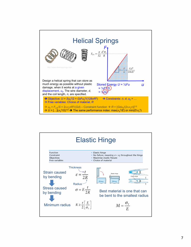
Elastic Hinge
Materials: engineering, science, processing and design, 2nd edition Copyright (c)2010 Michael Ashby, Hugh Shercliff, David Cebon
Table 7.5
Stress caused by bending
Minimum radius
Best material is one that canbe bent to the smallest radius
Thickness
Radius
Strain caused by bending

8
Figure 7.7
Stress Concentrations
Materials: engineering, science, processing and design, 2nd edition Copyright (c)2010 Michael Ashby, Hugh Shercliff, David Cebon
Holes, slots, threads, and changes in section concentratestress locally – yielding will start at these places but theinitial yielding is not usually catastrophic
Stress concentration factor
σnom – nominal loadσmax – maximum local stressα – loading factorc – characteristic dimension ρsc – radius of curvature
Material Indices: Strong, Light Tie-Rod
Materials: engineering, science, processing and design, 2nd edition Copyright (c)2010 Michael Ashby, Hugh Shercliff, David Cebon
Table 7.1
ObjectiveMinimize mass
ConstraintsLength is specifiedMust not fail under F
Free VariablesMaterial choiceSection area (eliminate)
Maximize

9
Figure 7.8
Strength - Density
Materials: engineering, science, processing and design, 2nd edition Copyright (c)2010 Michael Ashby, Hugh Shercliff, David Cebon
Strong, Light Panel
Materials: engineering, science, processing and design, 2nd edition Copyright (c)2010 Michael Ashby, Hugh Shercliff, David Cebon
Table 7.2
Same procedure
• Set up an equation for mass• Find an expression for themaximum stress
• Use this express to eliminate thefree variable h
Maximize

10
Light, Strong Beam
Materials: engineering, science, processing and design, 2nd edition Copyright (c)2010 Michael Ashby, Hugh Shercliff, David Cebon
Table 7.3
For a beam, we are free to changethe shape as well as the dimensions
of the cross-section
For a square cross-section: