SE1, SEV pumps - Master Engineering · Introduction 4 1 SE1, SEV pumps SMARTdesign The smartdesign...
128
GRUNDFOS DATA BOOKLET SE1, SEV pumps 1.1 to 11 kW 50 Hz
Transcript of SE1, SEV pumps - Master Engineering · Introduction 4 1 SE1, SEV pumps SMARTdesign The smartdesign...
GRUNDFOS DATA BOOKLET
SE1, SEV pumps1.1 to 11 kW 50 Hz
Ta
ble
of c
on
ten
ts
2
SE1, SEV pumps
1. Introduction 3Introduction 3Applications 3SMARTdesign 4
2. Performance range 5Performance overview 5
3. Identification 6Type key 6Nameplate 7
4. Selection of product 8Ordering a pump 8
5. Product range 9Product range 9
6. Variants 18List of variants 18
7. Construction 20SE1 20SEV 24Material specification, SE1 and SEV standard pumps 28Material specification, SEV Q variant 30Material specification, SEV...S variant (on request) 32Material specification, SEV...R variant 34Material specification, SEV...D variant(on request) 36
8. Product description 38Features 38Operating conditions 40Motor range 41Pump controllers 41Frequency converter operation 41Approvals 42Wiring diagrams 43
9. Curve charts 45How to read the performance curves 45Curve conditions 46Performance tests 46Certificates 46Witness test 46
10. Performance curves and technical data 47SE1.50.65.22.(Ex).2 47SE1.50.65.30.(Ex).2 48SE1.50.65.40.(Ex).2 49SE1.50.80.22.(Ex).2 50SE1.50.80.30.(Ex).2 51SE1.50.80.40.(Ex).2 52SE1.80.80.15.(Ex).4 53SE1.80.80.22.(Ex).4 54SE1.80.80.30.(Ex).4 55SE1.80.80.40.(Ex).4 56SE1.80.80.55.(Ex).4 57SE1.80.80.75.(Ex).4 58SE1.80.100.15.(Ex).4 59SE1.80.100.22.(Ex).4 60SE1.80.100.30.(Ex).4 61
SE1.80.100.40.(Ex).4 62SE1.80.100.55.(Ex).4 63SE1.80.100.75.(Ex).4 64SE1.100.100.40.(Ex).4 65SE1.100.100.55.(Ex).4 66SE1.100.100.75.(Ex).4 67SE1.100.150.40.(Ex).4 68SE1.100.150.55.(Ex).4 69SE1.100.150.75.(Ex).4 70SEV.65.65.22.(Ex).2 71SEV.65.65.30.(Ex).2 72SEV.65.65.40.(Ex).2 73SEV.65.80.22.(Ex).2 74SEV.65.80.30.(Ex).2 75SEV.65.80.40.(Ex).2 76SEV.80.80.11.(Ex).4 77SEV.80.80.13.(Ex).4 78SEV.80.80.15.(Ex).4 79SEV.80.80.22.(Ex).4 80SEV.80.80.40.(Ex).4 81SEV.80.80.40.(Ex).2 82SEV.80.80.60.(Ex).2 83SEV.80.80.75.(Ex).2 84SEV.80.80.92.(Ex).2 85SEV.80.80.110.(Ex).2 86SEV.80.100.11.(Ex).4 87SEV.80.100.13.(Ex).4 88SEV.80.100.15.(Ex).4 89SEV.80.100.22.(Ex).4 90SEV.80.100.40.(Ex).4 91SEV.80.100.40.(Ex).2 92SEV.80.100.60.(Ex).2 93SEV.80.100.75.(Ex).2 94SEV.80.100.92.(Ex).2 95SEV.80.100.110.(Ex).2 96SEV.100.100.30.(Ex).4 97SEV.100.100.40.(Ex).4 98SEV.100.100.55.(Ex).4 99SEV.100.100.75.(Ex).4 100
11. Dimensions 101Pumps without accessories 101Pump dimensions 102
12. Accessories 116Installation systems 116Level controllers 118
13. Further product documentation 122WebCAPS 122WinCAPS 123
Intr
od
uc
tio
n
SE1, SEV pumps 1
1. Introduction
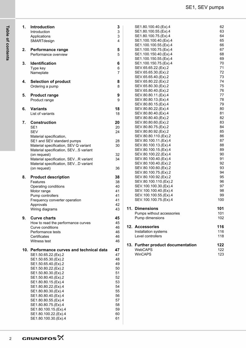
IntroductionThis data booklet deals with Grundfos sewage and wastewater pump types SE1 and SEV.
These pump types are available:
• SE1 pumps with S-tube impeller
• SEV pumps with SuperVortex (free-flow) impeller.
Fig. 1 SE1 and SEV pumps
The pumps are SuperVortex or S-tube impeller pumps specifically designed for pumping sewage and wastewater in a wide range of municipal, private and industrial applications.
The pumps are made of wear-resistant materials, such as cast iron and stainless steel. These materials ensure long and reliable operation.
The pumps are fitted with motors of 1.1 kW up to and including 11 kW. The motors are either 2- or 4-pole motors, depending on the motor size.
The free passage (spherical) in the pumps is 50 to 100 mm, depending on pump type.
The pumps are available for these types of installation:
• dry installation, vertical or horizontal
• submerged installation on auto-coupling system
• submerged installation, free-standing on ring stand.
ApplicationsThe typical application is the transfer of liquids such as:
• wastewater with a high content of fibres
• drainage water and surface water
• domestic wastewater
• municipal wastewater
• industrial wastewater
• process and cooling water.
The pumps are ideal for pumping the above liquids from places such as:
• municipal network pumping stations
• inlet pumping stations in wastewater treatment plants
• primary and secondary clarification in wastewater treatment plants
• stormwater pumping stations
• public buildings
• blocks of flats
• factories/industry.
TM
04
80
07
32
10
The S-tube impeller is the only impeller available in the wastewater market that does not compromise either efficiency or free passage through the pump.
3
Intro
du
ctio
n
4
SE1, SEV pumps1
SMARTdesign
The smartdesign features of our SE1 and SEV pumps include:
• designed for dry and submerged installation (without the need for external cooling)
• moisture-proof cable plug connection made of corrosion-resistant stainless steel with conductors embedded in polyethane sealant
• stainless steel clamp connection between motor housing and pump housing for easy service
• double mechanical cartridge shaft seal for easy service and perfect seal face alignment
• power supply cable incorporating wires for thermal sensors in the motor windings
• no additional cable required for sensors in pumps with sensors
• monitoring of operating conditions for pumps with sensors
• moisture detector for continuous monitoring of motor enclosure and automatic cut-out in case of leakage
• heavy-duty bearings greased for life
• pumps built for frequency converter operation
• smooth pump surface preventing dirt and impurities from sticking to the pump
• self-cleaning S-tube impeller with long vane reducing the risk of jamming or clogging, or SuperVortex impeller with high pumping efficiency and less downtime
• explosion-proof motors for potentially explosive environments
• motor insulation class F (155 °C)
• enclosure class IP68 with one thermal sensor in each phase.
smartdesign describes the functional design of our products that combines elegant appearance with smart features, created with customer needs in mind. smartdesign doesn't only look good; the design also makes installation, operation and maintenance of the product easier and more user-friendly.
Pe
rfo
rma
nc
e r
an
ge
SE1, SEV pumps 2
2. Performance range
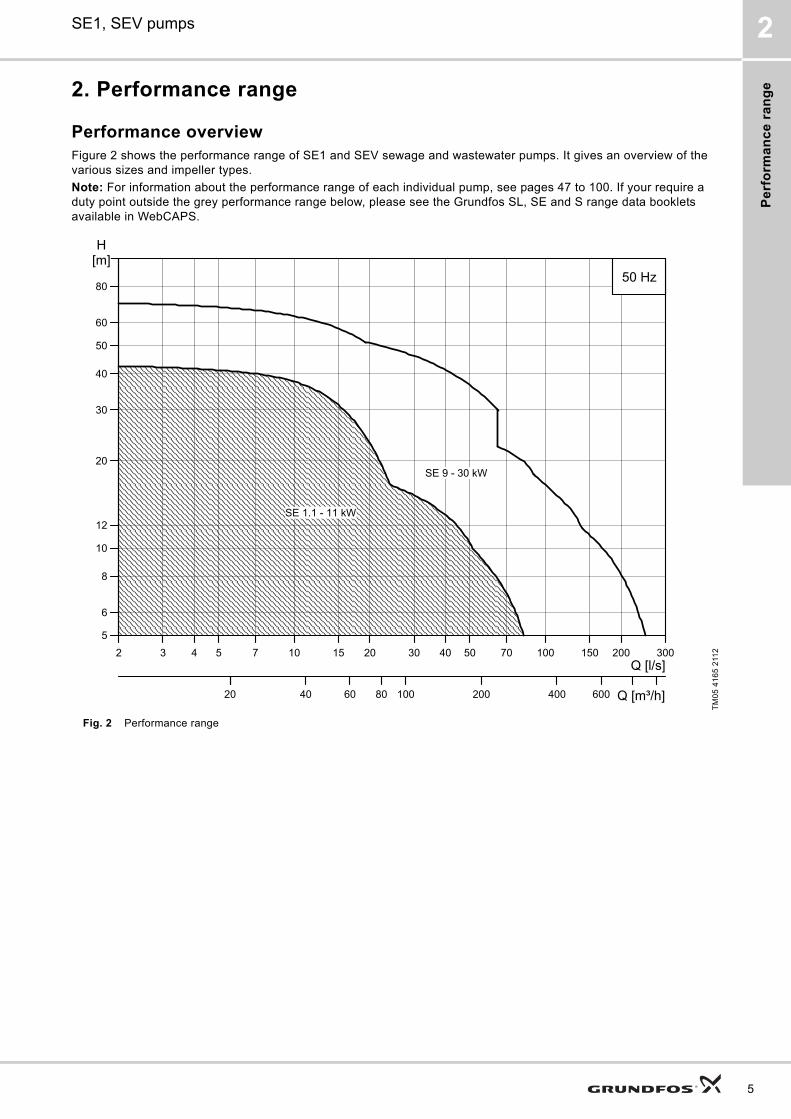
Performance overviewFigure 2 shows the performance range of SE1 and SEV sewage and wastewater pumps. It gives an overview of the various sizes and impeller types.
Note: For information about the performance range of each individual pump, see pages 47 to 100. If your require a duty point outside the grey performance range below, please see the Grundfos SL, SE and S range data booklets available in WebCAPS.
Fig. 2 Performance rangeT
M0
5 4
16
5 2
1122 3 4 5 7 10 15 20 30 40 50 70 100 150 200 300
Q [l/s]
5
6
8
10
12
20
30
40
50
60
80
H[m]
2020 40 60 80 100 200 400 600 Q [m³/h]
50 Hz
SE 9 - 30 kW
SE 1.1 - 11 kW
5
Ide
ntific
atio
n
6
SE1, SEV pumps3
3. Identification
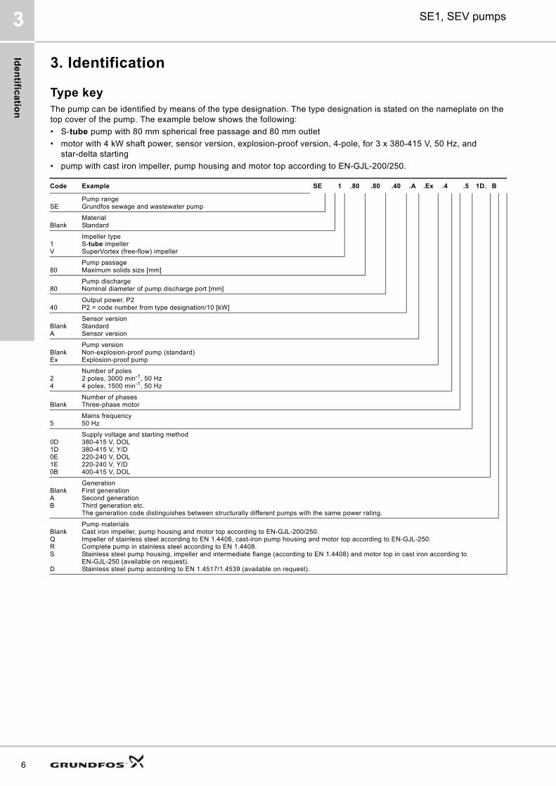
Type keyThe pump can be identified by means of the type designation. The type designation is stated on the nameplate on the top cover of the pump. The example below shows the following:
• S-tube pump with 80 mm spherical free passage and 80 mm outlet
• motor with 4 kW shaft power, sensor version, explosion-proof version, 4-pole, for 3 x 380-415 V, 50 Hz, and star-delta starting
• pump with cast iron impeller, pump housing and motor top according to EN-GJL-200/250.
Code Example SE 1 .80 .80 .40 .A .Ex .4 .5 1D. B
SEPump rangeGrundfos sewage and wastewater pump
BlankMaterialStandard
1V
Impeller typeS-tube impellerSuperVortex (free-flow) impeller
80Pump passageMaximum solids size [mm]
80Pump dischargeNominal diameter of pump discharge port [mm]
40Output power, P2P2 = code number from type designation/10 [kW]
BlankA
Sensor versionStandardSensor version
BlankEx
Pump versionNon-explosion-proof pump (standard)Explosion-proof pump
24
Number of poles2 poles, 3000 min-1, 50 Hz4 poles, 1500 min-1, 50 Hz
BlankNumber of phasesThree-phase motor
5 Mains frequency50 Hz
0D1D0E1E 0B
Supply voltage and starting method380-415 V, DOL380-415 V, Y/D220-240 V, DOL220-240 V, Y/D400-415 V, DOL
BlankAB
GenerationFirst generationSecond generationThird generation etc.The generation code distinguishes between structurally different pumps with the same power rating.
BlankQRS
D
Pump materialsCast iron impeller, pump housing and motor top according to EN-GJL-200/250.Impeller of stainless steel according to EN 1.4408, cast-iron pump housing and motor top according to EN-GJL-250.Complete pump in stainless steel according to EN 1.4408. Stainless steel pump housing, impeller and intermediate flange (according to EN 1.4408) and motor top in cast iron according to EN-GJL-250 (available on request).Stainless steel pump according to EN 1.4517/1.4539 (available on request).
Ide
nti
fic
ati
on
SE1, SEV pumps 3
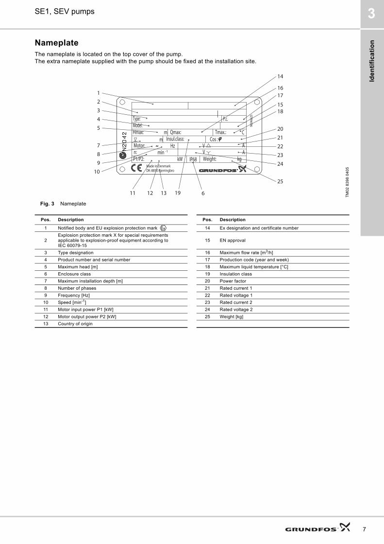
NameplateThe nameplate is located on the top cover of the pump. The extra nameplate supplied with the pump should be fixed at the installation site.
Fig. 3 Nameplate
TM
02
83
98
04
05
2
18
1
12 1311
1716
15
19
20
21
22
23
24
25
3
4
5
6
7
8
9
10
P.c.
mm
C
14
Made in DenmarkDK-8850 Bjerringbro
9604
6625
Insul.class:
kg
Cos :
kWP1/P2:
AA
VV
Motor: Hz-1minn:
IP68
Qmax:Hmax: Tmax.:
Type:
Weight:
Model:
Pos. Description Pos. Description
1 Notified body and EU explosion protection mark 14 Ex designation and certificate number
2Explosion protection mark X for special requirements applicable to explosion-proof equipment according toIEC 60079-15
15 EN approval
3 Type designation 16 Maximum flow rate [m3/h]
4 Product number and serial number 17 Production code (year and week)
5 Maximum head [m] 18 Maximum liquid temperature [°C]
6 Enclosure class 19 Insulation class
7 Maximum installation depth [m] 20 Power factor
8 Number of phases 21 Rated current 1
9 Frequency [Hz] 22 Rated voltage 1
10 Speed [min-1] 23 Rated current 2
11 Motor input power P1 [kW] 24 Rated voltage 2
12 Motor output power P2 [kW] 25 Weight [kg]
13 Country of origin
7
Se
lec
tion
of p
rod
uc
t
8
SE1, SEV pumps4
4. Selection of product
Ordering a pumpWhen ordering a pump, you have to take the following aspects into consideration:
• pump type
• custom-built variation (option)
• explosion-proof version
• accessories
• pump controller.
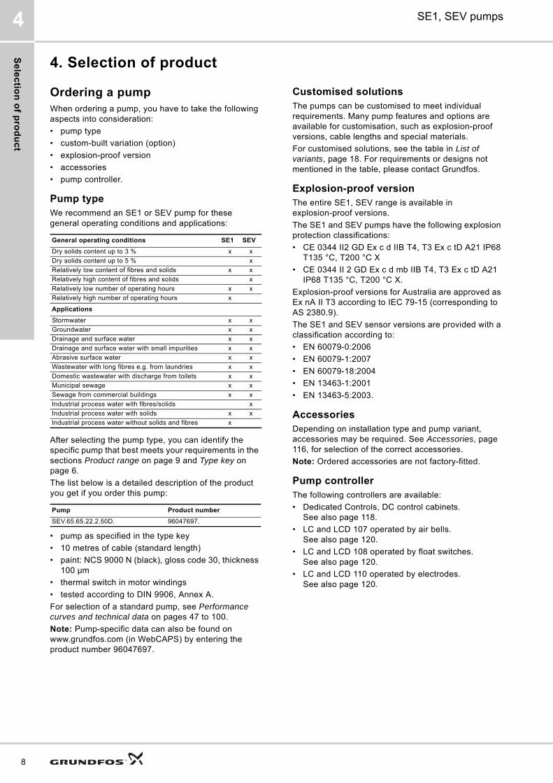
Pump typeWe recommend an SE1 or SEV pump for these general operating conditions and applications:
After selecting the pump type, you can identify the specific pump that best meets your requirements in the sections Product range on page 9 and Type key on page 6.
The list below is a detailed description of the product you get if you order this pump:
• pump as specified in the type key
• 10 metres of cable (standard length)
• paint: NCS 9000 N (black), gloss code 30, thickness 100 μm
• thermal switch in motor windings
• tested according to DIN 9906, Annex A.
For selection of a standard pump, see Performance curves and technical data on pages 47 to 100.
Note: Pump-specific data can also be found on www.grundfos.com (in WebCAPS) by entering the product number 96047697.
Customised solutionsThe pumps can be customised to meet individual requirements. Many pump features and options are available for customisation, such as explosion-proof versions, cable lengths and special materials.
For customised solutions, see the table in List of variants, page 18. For requirements or designs not mentioned in the table, please contact Grundfos.
Explosion-proof versionThe entire SE1, SEV range is available in explosion-proof versions.
The SE1 and SEV pumps have the following explosion protection classifications:
• CE 0344 II2 GD Ex c d IIB T4, T3 Ex c tD A21 IP68 T135 °C, T200 °C X
• CE 0344 II 2 GD Ex c d mb IIB T4, T3 Ex c tD A21 IP68 T135 °C, T200 °C X.
Explosion-proof versions for Australia are approved as Ex nA II T3 according to IEC 79-15 (corresponding to AS 2380.9).
The SE1 and SEV sensor versions are provided with a classification according to:
• EN 60079-0:2006
• EN 60079-1:2007
• EN 60079-18:2004
• EN 13463-1:2001
• EN 13463-5:2003.
AccessoriesDepending on installation type and pump variant, accessories may be required. See Accessories, page 116, for selection of the correct accessories.
Note: Ordered accessories are not factory-fitted.
Pump controllerThe following controllers are available:
• Dedicated Controls, DC control cabinets. See also page 118.
• LC and LCD 107 operated by air bells. See also page 120.
• LC and LCD 108 operated by float switches. See also page 120.
• LC and LCD 110 operated by electrodes.See also page 120.
General operating conditions SE1 SEV
Dry solids content up to 3 % x x
Dry solids content up to 5 % x
Relatively low content of fibres and solids x x
Relatively high content of fibres and solids x
Relatively low number of operating hours x x
Relatively high number of operating hours x
Applications
Stormwater x x
Groundwater x x
Drainage and surface water x x
Drainage and surface water with small impurities x x
Abrasive surface water x x
Wastewater with long fibres e.g. from laundries x x
Domestic wastewater with discharge from toilets x x
Municipal sewage x x
Sewage from commercial buildings x x
Industrial process water with fibres/solids x
Industrial process water with solids x x
Industrial process water without solids and fibres x
Pump Product number
SEV.65.65.22.2.50D. 96047697.
Pro
du
ct
ran
ge
SE1, SEV pumps 5
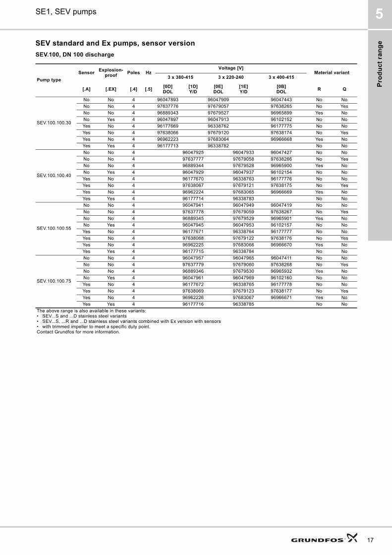
5. Product range
Product range
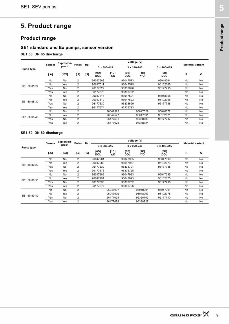
SE1 standard and Ex pumps, sensor version
SE1.50, DN 65 discharge
SE1.50, DN 80 discharge
Pump type
SensorExplosion-
proofPoles Hz
Voltage [V]Material variant
3 x 380-415 3 x 220-240 3 x 400-415
[.A] [.EX] [.2] [.5][0D]DOL
[1D]Y/D
[0E]DOL
[1E]Y/D
[0B]DOL
R Q
SE1.50.65.22
No No 2 96047509 96047513 96048364 No No
No Yes 2 96047511 96047515 96102066 No No
Yes No 2 96177629 96338698 96177735 No No
Yes Yes 2 96177673 96338722 No No
SE1.50.65.30
No No 2 96047517 96047521 96048368 No No
No Yes 2 96047519 96047523 96102068 No No
Yes No 2 96177630 96338699 96177736 No No
Yes Yes 2 96177674 96338723 No No
SE1.50.65.40
No No 2 96047525 96047529 96048372 No No
No Yes 2 96047527 96047531 96102071 No No
Yes No 2 96177631 96338700 96177737 No No
Yes Yes 2 96177675 96338724 No No
Pump type
SensorExplosion-
proofPoles Hz
Voltage [V]Material variant
3 x 380-415 3 x 220-240 3 x 400-415
[.A] [.EX] [.2] [.5][0D]DOL
[1D]Y/D
[0E]DOL
[1E]Y/D
[0B]DOL
R Q
SE1.50.80.22
No No 2 96047981 96047985 96047399 No No
No Yes 2 96047983 96047987 96102073 No No
Yes No 2 96177632 96338701 96177738 No No
Yes Yes 2 96177676 96338725 No No
SE1.50.80.30
No No 2 96047989 96047993 96047395 No No
No Yes 2 96047991 96047995 96102075 No No
Yes No 2 96177633 96338702 96177739 No No
Yes Yes 2 96177677 96338726 No No
SE1.50.80.40
No No 2 96047997 96048001 96047391 No No
No Yes 2 96047999 96048003 96102078 No No
Yes No 2 96177634 96338703 96177740 No No
Yes Yes 2 96177678 96338727 No No
9
Pro
du
ct ra
ng
e
10
SE1, SEV pumps5
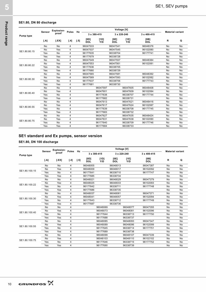
SE1.80, DN 80 discharge
SE1 standard and Ex pumps, sensor version
SE1.80, DN 100 discharge
Pump type
SensorExplosion-
proofPoles Hz
Voltage [V]Material variant
3 x 380-415 3 x 220-240 3 x 400-415
[.A] [.EX] [.4] [.5][0D]DOL
[1D]Y/D
[0E]DOL
[1E]Y/D
[0B]DOL
R Q
SE1.80.80.15
No No 4 96047533 96047541 96048376 No No
No Yes 4 96047537 96047545 96102080 No No
Yes No 4 96177635 96338704 96177741 No No
Yes Yes 4 96177679 96338728 No No
SE1.80.80.22
No No 4 96047549 96047557 96048384 No No
No Yes 4 96047553 96047561 96102081 No No
Yes No 4 96177636 96338705 No No
Yes Yes 4 96177680 96338729 No No
SE1.80.80.30
No No 4 96047565 96047581 96048392 No No
No Yes 4 96047569 96047593 96102082 No No
Yes No 4 96177637 96338706 96177743 No No
Yes Yes 4 96177681 96338730 No No
SE1.80.80.40
No No 4 96047597 96047605 96048408 No No
No Yes 4 96047601 96047609 96102084 No No
Yes No 4 96177638 96338707 96177744 No No
Yes Yes 4 96177682 96338731 No No
SE1.80.80.55
No No 4 96047613 96047621 96048416 No No
No Yes 4 96047617 96047624 96102087 No No
Yes No 4 96177639 96338708 96177745 No No
Yes Yes 4 96177683 96338732 No No
SE1.80.80.75
No No 4 96047627 96047635 96048424 No No
No Yes 4 96047631 96047638 96102090 No No
Yes No 4 96177640 96338709 96177746 No No
Yes Yes 4 96177684 96338733 No No
Pump type
SensorExplosion-
proofPoles Hz
Voltage [V]Material variant
3 x 380-415 3 x 220-240 3 x 400-415
[.A] [.EX] [.4] [.5][0D]DOL
[1D]Y/D
[0E]DOL
[1E]Y/D
[0B]DOL
R Q
SE1.80.100.15
No No 4 96048005 96048013 96047387 No No
No Yes 4 96048009 96048017 96102092 No No
Yes No 4 96177641 96338710 96177747 No No
Yes Yes 4 96177685 96338734 No No
SE1.80.100.22
No No 4 96048021 96048029 96047379 No No
No Yes 4 96048025 96048033 96102093 No No
Yes No 4 96177642 96338711 96177748 No No
Yes Yes 4 96177686 96338735 No No
SE1.80.100.30
No No 4 96048037 96048061 96047371 No No
No Yes 4 96048041 96048057 96102094 No No
Yes No 4 96177643 96338712 96177749 No No
Yes Yes 4 96177687 96338736 No No
SE1.80.100.40
No No 4 96048069 96048077 96047355 No No
No Yes 4 96048073 96048081 96102096 No No
Yes No 4 96177644 96338713 96177750 No No
Yes Yes 4 96177688 96338737 No No
SE1.80.100.55
No No 4 96048085 96048093 96047347 No No
No Yes 4 96048089 96048096 96102099 No No
Yes No 4 96177645 96338714 96177751 No No
Yes Yes 4 96177689 96338738 No No
SE1.80.100.75
No No 4 96048099 96048107 96047339 No No
No Yes 4 96048103 96048110 96102102 No No
Yes No 4 96177646 96338715 96177752 No No
Yes Yes 4 96177690 96338739 No No
Pro
du
ct
ran
ge
SE1, SEV pumps 5
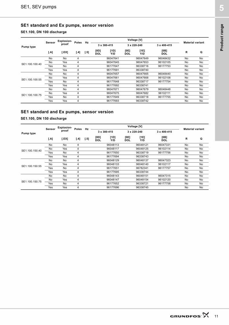
SE1 standard and Ex pumps, sensor version
SE1.100, DN 100 discharge
SE1 standard and Ex pumps, sensor version
SE1.100, DN 150 discharge
Pump type
SensorExplosion-
proofPoles Hz
Voltage [V]Material variant
3 x 380-415 3 x 220-240 3 x 400-415
[.A] [.EX] [.4] [.5][0D]DOL
[1D]Y/D
[0E]DOL
[1E]Y/D
[0B]DOL
R Q
SE1.100.100.40
No No 4 96047641 96047649 96048432 No No
No Yes 4 96047645 96047653 96102105 No No
Yes No 4 96177647 96338716 96177753 No No
Yes Yes 4 96177691 96338740 No No
SE1.100.100.55
No No 4 96047657 96047665 96048440 No No
No Yes 4 96047661 96047668 96102108 No No
Yes No 4 96177648 96338717 96177754 No No
Yes Yes 4 96177692 96338741 No No
SE1.100.100.75
No No 4 96047671 96047679 96048448 No No
No Yes 4 96047675 96047682 96102111 No No
Yes No 4 96177649 96338718 96177755 No No
Yes Yes 4 96177693 96338742 No No
Pump type
SensorExplosion-
proofPoles Hz
Voltage [V]Material variant
3 x 380-415 3 x 220-240 3 x 400-415
[.A] [.EX] [.4] [.5][0D]DOL
[1D]Y/D
[0E]DOL
[1E]Y/D
[0B]DOL
R Q
SE1.100.150.40
No No 4 96048113 96048121 96047331 No No
No Yes 4 96048117 96048125 96102114 No No
Yes No 4 96177650 96338719 96177756 No No
Yes Yes 4 96177694 96338743 No No
SE1.100.150.55
No No 4 96048129 96048137 96047323 No No
No Yes 4 96048133 96048140 96102117 No No
Yes No 4 96177651 96782341 96177757 No No
Yes Yes 4 96177695 96338744 No No
SE1.100.150.75
No No 4 96048143 96048151 96047315 No No
No Yes 4 96048147 96048154 96102120 No No
Yes No 4 96177652 96338721 96177758 No No
Yes Yes 4 96177696 96338745 No No
11
Pro
du
ct ra
ng
e
12
SE1, SEV pumps5
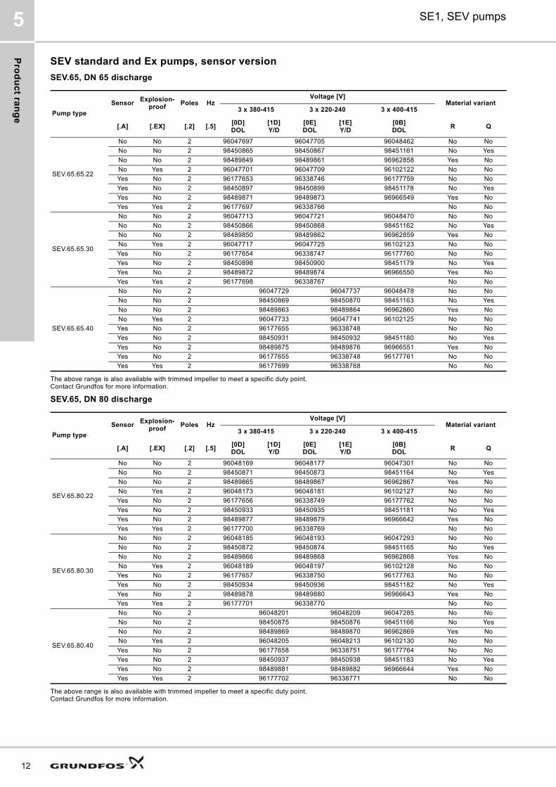
SEV standard and Ex pumps, sensor version
SEV.65, DN 65 discharge
The above range is also available with trimmed impeller to meet a specific duty point.Contact Grundfos for more information.
SEV.65, DN 80 discharge
The above range is also available with trimmed impeller to meet a specific duty point. Contact Grundfos for more information.
Pump type
SensorExplosion-
proofPoles Hz
Voltage [V]Material variant
3 x 380-415 3 x 220-240 3 x 400-415
[.A] [.EX] [.2] [.5][0D]DOL
[1D]Y/D
[0E]DOL
[1E]Y/D
[0B]DOL
R Q
SEV.65.65.22
No No 2 96047697 96047705 96048462 No No
No No 2 98450865 98450867 98451161 No Yes
No No 2 98489849 98489861 96962858 Yes No
No Yes 2 96047701 96047709 96102122 No No
Yes No 2 96177653 96338746 96177759 No No
Yes No 2 98450897 98450899 98451178 No Yes
Yes No 2 98489871 98489873 96966549 Yes No
Yes Yes 2 96177697 96338766 No No
SEV.65.65.30
No No 2 96047713 96047721 96048470 No No
No No 2 98450866 98450868 98451162 No Yes
No No 2 98489850 98489862 96962859 Yes No
No Yes 2 96047717 96047725 96102123 No No
Yes No 2 96177654 96338747 96177760 No No
Yes No 2 98450898 98450900 98451179 No Yes
Yes No 2 98489872 98489874 96966550 Yes No
Yes Yes 2 96177698 96338767 No No
SEV.65.65.40
No No 2 96047729 96047737 96048478 No No
No No 2 98450869 98450870 98451163 No Yes
No No 2 98489863 98489864 96962860 Yes No
No Yes 2 96047733 96047741 96102125 No No
Yes No 2 96177655 96338748 No No
Yes No 2 98450931 98450932 98451180 No Yes
Yes No 2 98489875 98489876 96966551 Yes No
Yes No 2 96177655 96338748 96177761 No No
Yes Yes 2 96177699 96338768 No No
Pump type
SensorExplosion-
proofPoles Hz
Voltage [V]Material variant
3 x 380-415 3 x 220-240 3 x 400-415
[.A] [.EX] [.2] [.5][0D]DOL
[1D]Y/D
[0E]DOL
[1E]Y/D
[0B]DOL
R Q
SEV.65.80.22
No No 2 96048169 96048177 96047301 No No
No No 2 98450871 98450873 98451164 No Yes
No No 2 98489865 98489867 96962867 Yes No
No Yes 2 96048173 96048181 96102127 No No
Yes No 2 96177656 96338749 96177762 No No
Yes No 2 98450933 98450935 98451181 No Yes
Yes No 2 98489877 98489879 96966642 Yes No
Yes Yes 2 96177700 96338769 No No
SEV.65.80.30
No No 2 96048185 96048193 96047293 No No
No No 2 98450872 98450874 98451165 No Yes
No No 2 98489866 98489868 96962868 Yes No
No Yes 2 96048189 96048197 96102128 No No
Yes No 2 96177657 96338750 96177763 No No
Yes No 2 98450934 98450936 98451182 No Yes
Yes No 2 98489878 98489880 96966643 Yes No
Yes Yes 2 96177701 96338770 No No
SEV.65.80.40
No No 2 96048201 96048209 96047285 No No
No No 2 98450875 98450876 98451166 No Yes
No No 2 98489869 98489870 96962869 Yes No
No Yes 2 96048205 96048213 96102130 No No
Yes No 2 96177658 96338751 96177764 No No
Yes No 2 98450937 98450938 98451183 No Yes
Yes No 2 98489881 98489882 96966644 Yes No
Yes Yes 2 96177702 96338771 No No
Pro
du
ct
ran
ge
SE1, SEV pumps 5
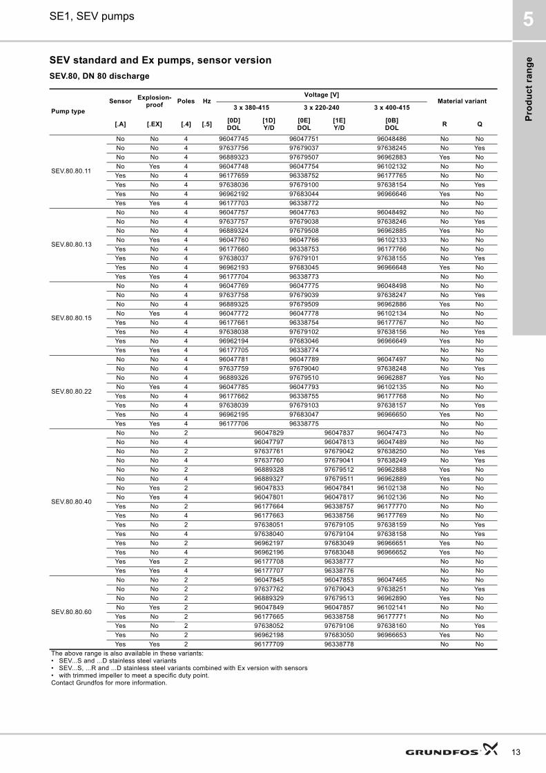
SEV standard and Ex pumps, sensor version
SEV.80, DN 80 discharge
Pump type
SensorExplosion-
proofPoles Hz
Voltage [V]Material variant
3 x 380-415 3 x 220-240 3 x 400-415
[.A] [.EX] [.4] [.5][0D]DOL
[1D]Y/D
[0E]DOL
[1E]Y/D
[0B]DOL
R Q
SEV.80.80.11
No No 4 96047745 96047751 96048486 No No
No No 4 97637756 97679037 97638245 No Yes
No No 4 96889323 97679507 96962883 Yes No
No Yes 4 96047748 96047754 96102132 No No
Yes No 4 96177659 96338752 96177765 No No
Yes No 4 97638036 97679100 97638154 No Yes
Yes No 4 96962192 97683044 96966646 Yes No
Yes Yes 4 96177703 96338772 No No
SEV.80.80.13
No No 4 96047757 96047763 96048492 No No
No No 4 97637757 97679038 97638246 No Yes
No No 4 96889324 97679508 96962885 Yes No
No Yes 4 96047760 96047766 96102133 No No
Yes No 4 96177660 96338753 96177766 No No
Yes No 4 97638037 97679101 97638155 No Yes
Yes No 4 96962193 97683045 96966648 Yes No
Yes Yes 4 96177704 96338773 No No
SEV.80.80.15
No No 4 96047769 96047775 96048498 No No
No No 4 97637758 97679039 97638247 No Yes
No No 4 96889325 97679509 96962886 Yes No
No Yes 4 96047772 96047778 96102134 No No
Yes No 4 96177661 96338754 96177767 No No
Yes No 4 97638038 97679102 97638156 No Yes
Yes No 4 96962194 97683046 96966649 Yes No
Yes Yes 4 96177705 96338774 No No
SEV.80.80.22
No No 4 96047781 96047789 96047497 No No
No No 4 97637759 97679040 97638248 No Yes
No No 4 96889326 97679510 96962887 Yes No
No Yes 4 96047785 96047793 96102135 No No
Yes No 4 96177662 96338755 96177768 No No
Yes No 4 97638039 97679103 97638157 No Yes
Yes No 4 96962195 97683047 96966650 Yes No
Yes Yes 4 96177706 96338775 No No
SEV.80.80.40
No No 2 96047829 96047837 96047473 No No
No No 4 96047797 96047813 96047489 No No
No No 2 97637761 97679042 97638250 No Yes
No No 4 97637760 97679041 97638249 No Yes
No No 2 96889328 97679512 96962888 Yes No
No No 4 96889327 97679511 96962889 Yes No
No Yes 2 96047833 96047841 96102138 No No
No Yes 4 96047801 96047817 96102136 No No
Yes No 2 96177664 96338757 96177770 No No
Yes No 4 96177663 96338756 96177769 No No
Yes No 2 97638051 97679105 97638159 No Yes
Yes No 4 97638040 97679104 97638158 No Yes
Yes No 2 96962197 97683049 96966651 Yes No
Yes No 4 96962196 97683048 96966652 Yes No
Yes Yes 2 96177708 96338777 No No
Yes Yes 4 96177707 96338776 No No
SEV.80.80.60
No No 2 96047845 96047853 96047465 No No
No No 2 97637762 97679043 97638251 No Yes
No No 2 96889329 97679513 96962890 Yes No
No Yes 2 96047849 96047857 96102141 No No
Yes No 2 96177665 96338758 96177771 No No
Yes No 2 97638052 97679106 97638160 No Yes
Yes No 2 96962198 97683050 96966653 Yes No
Yes Yes 2 96177709 96338778 No No
The above range is also available in these variants:• SEV...S and ...D stainless steel variants• SEV...S, ...R and ...D stainless steel variants combined with Ex version with sensors• with trimmed impeller to meet a specific duty point.Contact Grundfos for more information.
13

Pro
du
ct ra
ng
e
14
SE1, SEV pumps5
SEV.80.80.75
No No 2 96047861 96047869 96047457 No No
No No 2 97637763 97679044 97638252 No Yes
No No 2 96889330 97679514 96980890 Yes No
No Yes 2 96047865 96047873 96102144 No No
Yes No 2 96177666 96338759 96177772 No No
Yes No 2 97638053 97679107 97638161 No Yes
Yes No 2 96962199 97683051 96966654 Yes No
Yes Yes 2 96177710 96338779 No No
SEV.80.80.92
No No 2 96047207 96047195 96047201 No No
No No 2 97637764 97679045 97638253 No Yes
No No 2 96889331 97679515 96962891 Yes No
No Yes 2 96047204 96047192 96102147 No No
Yes No 2 96177667 96338760 96177773 No No
Yes No 2 97638054 97679108 97638162 No Yes
Yes No 2 96962200 97683052 96966655 Yes No
Yes Yes 2 96177711 96338780 No No
SEV.80.80.110
No No 2 96047877 96047885 96047449 No No
No No 2 97637765 97679046 97638254 No Yes
No No 2 96889332 97679516 96962892 Yes No
No Yes 2 96047881 96047889 96102150 No No
Yes No 2 96177668 96338761 96177774 No No
Yes No 2 97638055 97679109 97638163 No Yes
Yes No 2 96962201 97683053 96966656 Yes No
Yes Yes 2 96177712 96338781 No No
Pump type
SensorExplosion-
proofPoles Hz
Voltage [V]Material variant
3 x 380-415 3 x 220-240 3 x 400-415
[.A] [.EX] [.4] [.5][0D]DOL
[1D]Y/D
[0E]DOL
[1E]Y/D
[0B]DOL
R Q
The above range is also available in these variants:• SEV...S and ...D stainless steel variants• SEV...S, ...R and ...D stainless steel variants combined with Ex version with sensors• with trimmed impeller to meet a specific duty point.Contact Grundfos for more information.
Pro
du
ct
ran
ge
SE1, SEV pumps 5
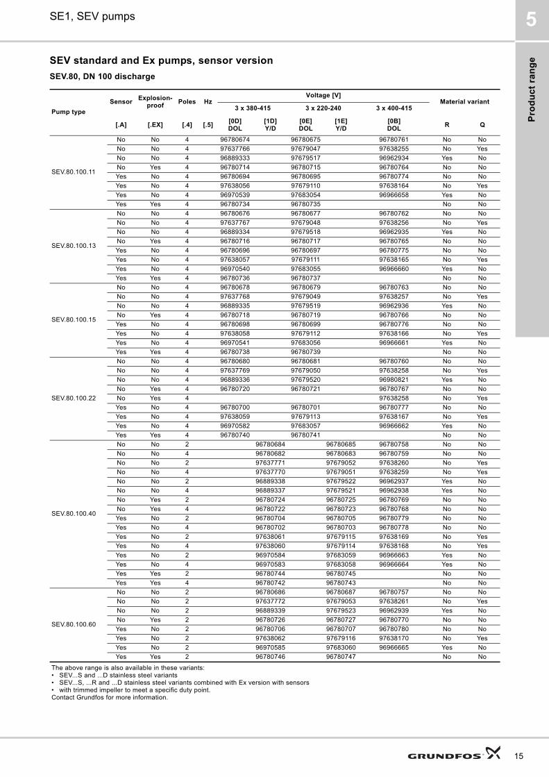
SEV standard and Ex pumps, sensor version
SEV.80, DN 100 discharge
Pump type
SensorExplosion-
proofPoles Hz
Voltage [V]Material variant
3 x 380-415 3 x 220-240 3 x 400-415
[.A] [.EX] [.4] [.5][0D]DOL
[1D]Y/D
[0E]DOL
[1E]Y/D
[0B]DOL
R Q
SEV.80.100.11
No No 4 96780674 96780675 96780761 No No
No No 4 97637766 97679047 97638255 No Yes
No No 4 96889333 97679517 96962934 Yes No
No Yes 4 96780714 96780715 96780764 No No
Yes No 4 96780694 96780695 96780774 No No
Yes No 4 97638056 97679110 97638164 No Yes
Yes No 4 96970539 97683054 96966658 Yes No
Yes Yes 4 96780734 96780735 No No
SEV.80.100.13
No No 4 96780676 96780677 96780762 No No
No No 4 97637767 97679048 97638256 No Yes
No No 4 96889334 97679518 96962935 Yes No
No Yes 4 96780716 96780717 96780765 No No
Yes No 4 96780696 96780697 96780775 No No
Yes No 4 97638057 97679111 97638165 No Yes
Yes No 4 96970540 97683055 96966660 Yes No
Yes Yes 4 96780736 96780737 No No
SEV.80.100.15
No No 4 96780678 96780679 96780763 No No
No No 4 97637768 97679049 97638257 No Yes
No No 4 96889335 97679519 96962936 Yes No
No Yes 4 96780718 96780719 96780766 No No
Yes No 4 96780698 96780699 96780776 No No
Yes No 4 97638058 97679112 97638166 No Yes
Yes No 4 96970541 97683056 96966661 Yes No
Yes Yes 4 96780738 96780739 No No
SEV.80.100.22
No No 4 96780680 96780681 96780760 No No
No No 4 97637769 97679050 97638258 No Yes
No No 4 96889336 97679520 96980821 Yes No
No Yes 4 96780720 96780721 96780767 No No
No Yes 4 97638258 No Yes
Yes No 4 96780700 96780701 96780777 No No
Yes No 4 97638059 97679113 97638167 No Yes
Yes No 4 96970582 97683057 96966662 Yes No
Yes Yes 4 96780740 96780741 No No
SEV.80.100.40
No No 2 96780684 96780685 96780758 No No
No No 4 96780682 96780683 96780759 No No
No No 2 97637771 97679052 97638260 No Yes
No No 4 97637770 97679051 97638259 No Yes
No No 2 96889338 97679522 96962937 Yes No
No No 4 96889337 97679521 96962938 Yes No
No Yes 2 96780724 96780725 96780769 No No
No Yes 4 96780722 96780723 96780768 No No
Yes No 2 96780704 96780705 96780779 No No
Yes No 4 96780702 96780703 96780778 No No
Yes No 2 97638061 97679115 97638169 No Yes
Yes No 4 97638060 97679114 97638168 No Yes
Yes No 2 96970584 97683059 96966663 Yes No
Yes No 4 96970583 97683058 96966664 Yes No
Yes Yes 2 96780744 96780745 No No
Yes Yes 4 96780742 96780743 No No
SEV.80.100.60
No No 2 96780686 96780687 96780757 No No
No No 2 97637772 97679053 97638261 No Yes
No No 2 96889339 97679523 96962939 Yes No
No Yes 2 96780726 96780727 96780770 No No
Yes No 2 96780706 96780707 96780780 No No
Yes No 2 97638062 97679116 97638170 No Yes
Yes No 2 96970585 97683060 96966665 Yes No
Yes Yes 2 96780746 96780747 No No
The above range is also available in these variants:• SEV...S and ...D stainless steel variants• SEV...S, ...R and ...D stainless steel variants combined with Ex version with sensors• with trimmed impeller to meet a specific duty point.Contact Grundfos for more information.
15
Pro
du
ct ra
ng
e
16
SE1, SEV pumps5
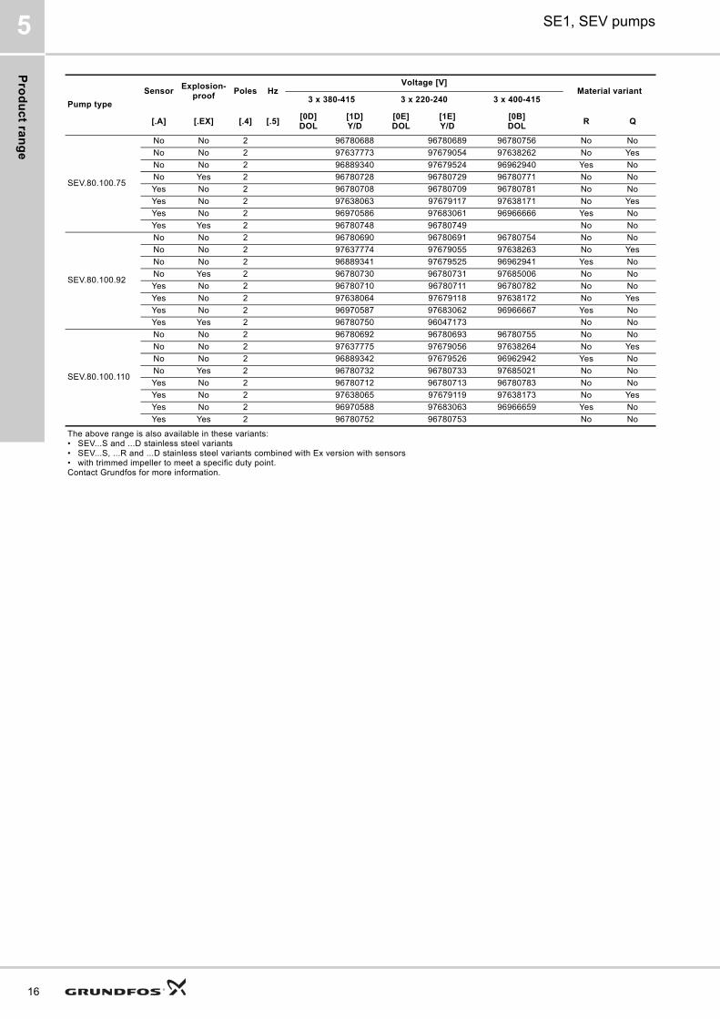
SEV.80.100.75
No No 2 96780688 96780689 96780756 No No
No No 2 97637773 97679054 97638262 No Yes
No No 2 96889340 97679524 96962940 Yes No
No Yes 2 96780728 96780729 96780771 No No
Yes No 2 96780708 96780709 96780781 No No
Yes No 2 97638063 97679117 97638171 No Yes
Yes No 2 96970586 97683061 96966666 Yes No
Yes Yes 2 96780748 96780749 No No
SEV.80.100.92
No No 2 96780690 96780691 96780754 No No
No No 2 97637774 97679055 97638263 No Yes
No No 2 96889341 97679525 96962941 Yes No
No Yes 2 96780730 96780731 97685006 No No
Yes No 2 96780710 96780711 96780782 No No
Yes No 2 97638064 97679118 97638172 No Yes
Yes No 2 96970587 97683062 96966667 Yes No
Yes Yes 2 96780750 96047173 No No
SEV.80.100.110
No No 2 96780692 96780693 96780755 No No
No No 2 97637775 97679056 97638264 No Yes
No No 2 96889342 97679526 96962942 Yes No
No Yes 2 96780732 96780733 97685021 No No
Yes No 2 96780712 96780713 96780783 No No
Yes No 2 97638065 97679119 97638173 No Yes
Yes No 2 96970588 97683063 96966659 Yes No
Yes Yes 2 96780752 96780753 No No
Pump type
SensorExplosion-
proofPoles Hz
Voltage [V]Material variant
3 x 380-415 3 x 220-240 3 x 400-415
[.A] [.EX] [.4] [.5][0D]DOL
[1D]Y/D
[0E]DOL
[1E]Y/D
[0B]DOL
R Q
The above range is also available in these variants:• SEV...S and ...D stainless steel variants• SEV...S, ...R and ...D stainless steel variants combined with Ex version with sensors• with trimmed impeller to meet a specific duty point.Contact Grundfos for more information.
Pro
du
ct
ran
ge
SE1, SEV pumps 5
SEV standard and Ex pumps, sensor version
SEV.100, DN 100 discharge
Pump type
SensorExplosion-
proofPoles Hz
Voltage [V]Material variant
3 x 380-415 3 x 220-240 3 x 400-415
[.A] [.EX] [.4] [.5][0D]DOL
[1D]Y/D
[0E]DOL
[1E]Y/D
[0B]DOL
R Q
SEV.100.100.30
No No 4 96047893 96047909 96047443 No No
No No 4 97637776 97679057 97638265 No Yes
No No 4 96889343 97679527 96965899 Yes No
No Yes 4 96047897 96047913 96102152 No No
Yes No 4 96177669 96338762 96177775 No No
Yes No 4 97638066 97679120 97638174 No Yes
Yes No 4 96962223 97683064 96966668 Yes No
Yes Yes 4 96177713 96338782 No No
SEV.100.100.40
No No 4 96047925 96047933 96047427 No No
No No 4 97637777 97679058 97638266 No Yes
No No 4 96889344 97679528 96965900 Yes No
No Yes 4 96047929 96047937 96102154 No No
Yes No 4 96177670 96338763 96177776 No No
Yes No 4 97638067 97679121 97638175 No Yes
Yes No 4 96962224 97683065 96966669 Yes No
Yes Yes 4 96177714 96338783 No No
SEV.100.100.55
No No 4 96047941 96047949 96047419 No No
No No 4 97637778 97679059 97638267 No Yes
No No 4 96889345 97679529 96965901 Yes No
No Yes 4 96047945 96047953 96102157 No No
Yes No 4 96177671 96338764 96177777 No No
Yes No 4 97638068 97679122 97638176 No Yes
Yes No 4 96962225 97683066 96966670 Yes No
Yes Yes 4 96177715 96338784 No No
SEV.100.100.75
No No 4 96047957 96047965 96047411 No No
No No 4 97637779 97679060 97638268 No Yes
No No 4 96889346 97679530 96965932 Yes No
No Yes 4 96047961 96047969 96102160 No No
Yes No 4 96177672 96338765 96177778 No No
Yes No 4 97638069 97679123 97638177 No Yes
Yes No 4 96962226 97683067 96966671 Yes No
Yes Yes 4 96177716 96338785 No No
The above range is also available in these variants:• SEV...S and ...D stainless steel variants• SEV...S, ...R and ...D stainless steel variants combined with Ex version with sensors• with trimmed impeller to meet a specific duty point.Contact Grundfos for more information.
17
Va
rian
ts
18
SE1, SEV pumps6
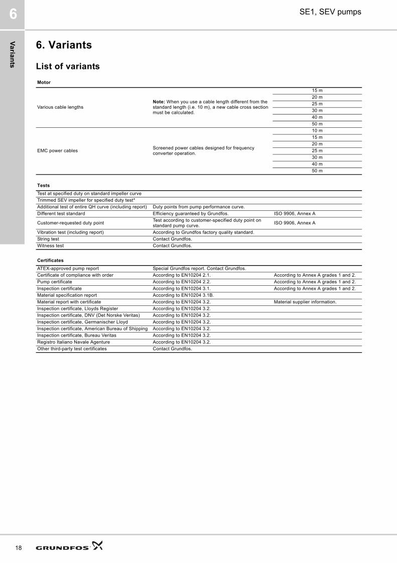
6. Variants
List of variants
Motor
Various cable lengthsNote: When you use a cable length different from the standard length (i.e. 10 m), a new cable cross section must be calculated.
15 m
20 m
25 m
30 m
40 m
50 m
EMC power cablesScreened power cables designed for frequency converter operation.
10 m
15 m
20 m
25 m
30 m
40 m
50 m
Tests
Test at specified duty on standard impeller curve
Trimmed SEV impeller for specified duty test*
Additional test of entire QH curve (including report) Duty points from pump performance curve.
Different test standard Efficiency guaranteed by Grundfos. ISO 9906, Annex A
Customer-requested duty pointTest according to customer-specified duty point on standard pump curve.
ISO 9906, Annex A
Vibration test (including report) According to Grundfos factory quality standard.
String test Contact Grundfos.
Witness test Contact Grundfos.
Certificates
ATEX-approved pump report Special Grundfos report. Contact Grundfos.
Certificate of compliance with order According to EN10204 2.1. According to Annex A grades 1 and 2.
Pump certificate According to EN10204 2.2. According to Annex A grades 1 and 2.
Inspection certificate According to EN10204 3.1. According to Annex A grades 1 and 2.
Material specification report According to EN10204 3.1B.
Material report with certificate According to EN10204 3.2. Material supplier information.
Inspection certificate, Lloyds Register According to EN10204 3.2.
Inspection certificate, DNV (Det Norske Veritas) According to EN10204 3.2.
Inspection certificate, Germanischer Lloyd According to EN10204 3.2.
Inspection certificate, American Bureau of Shipping According to EN10204 3.2.
Inspection certificate, Bureau Veritas According to EN10204 3.2.
Registro Italiano Navale Agenture According to EN10204 3.2.
Other third-party test certificates Contact Grundfos.
Va
ria
nts
SE1, SEV pumps 6
* SEV impellers can be trimmed on request.
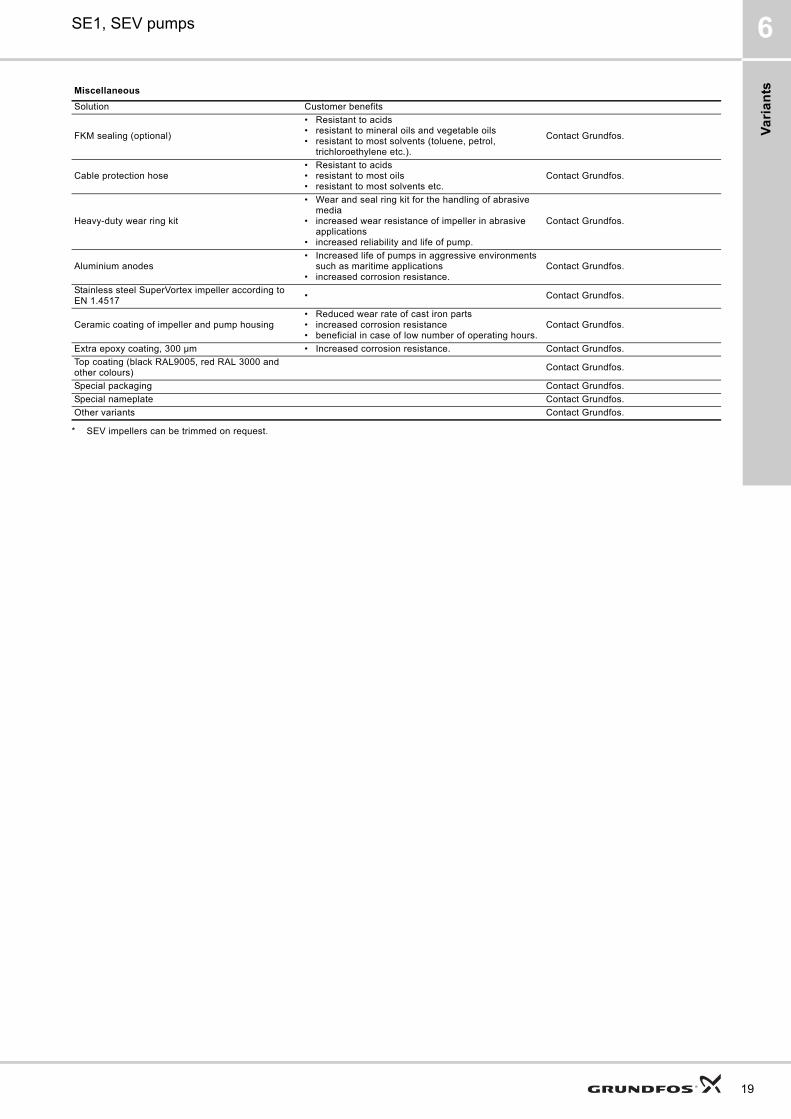
Miscellaneous
Solution Customer benefits
FKM sealing (optional)
• Resistant to acids• resistant to mineral oils and vegetable oils• resistant to most solvents (toluene, petrol,
trichloroethylene etc.).
Contact Grundfos.
Cable protection hose• Resistant to acids• resistant to most oils• resistant to most solvents etc.
Contact Grundfos.
Heavy-duty wear ring kit
• Wear and seal ring kit for the handling of abrasive media
• increased wear resistance of impeller in abrasive applications
• increased reliability and life of pump.
Contact Grundfos.
Aluminium anodes• Increased life of pumps in aggressive environments
such as maritime applications• increased corrosion resistance.
Contact Grundfos.
Stainless steel SuperVortex impeller according to EN 1.4517
• Contact Grundfos.
Ceramic coating of impeller and pump housing• Reduced wear rate of cast iron parts• increased corrosion resistance• beneficial in case of low number of operating hours.
Contact Grundfos.
Extra epoxy coating, 300 μm • Increased corrosion resistance. Contact Grundfos.
Top coating (black RAL9005, red RAL 3000 and other colours)
Contact Grundfos.
Special packaging Contact Grundfos.
Special nameplate Contact Grundfos.
Other variants Contact Grundfos.
19
Co
ns
truc
tion
20
SE1, SEV pumps7
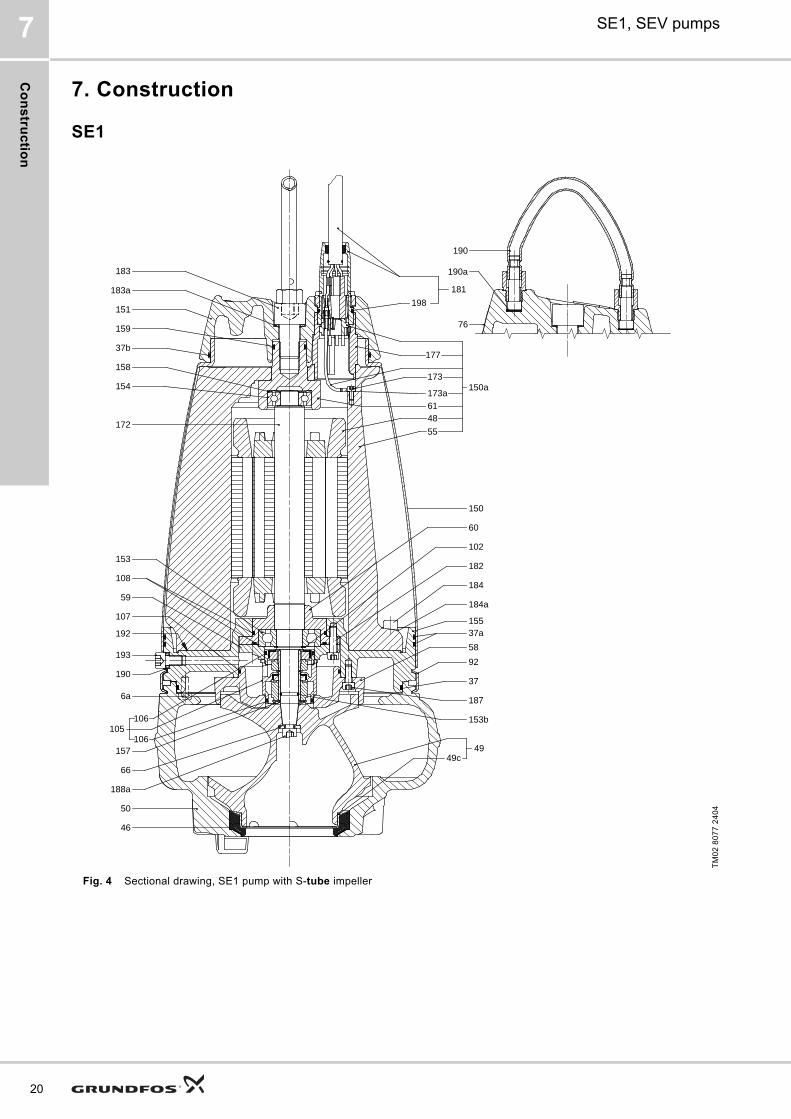
7. Construction
SE1
Fig. 4 Sectional drawing, SE1 pump with S-tube impeller
TM
02
80
77
24
04
190
190a
76
198
181
151
159
37b
173
173a
48
55
183a
183
158
154
49c49
172
153
108
107
192
193
190
6a
157
188a
50
46
60
102
182
155
58
92
37
187
153b
59
150
66
184a
184
177
150a
61
105106
106
37a
Co
ns
tru
cti
on
SE1, SEV pumps 7
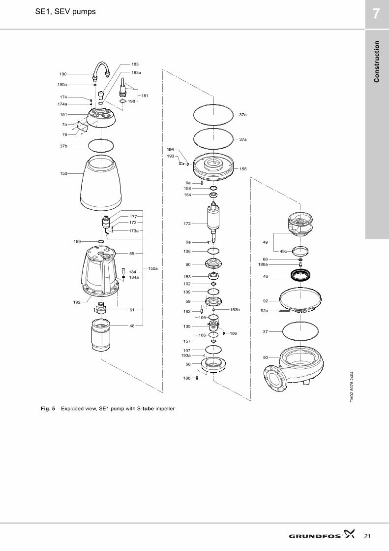
Fig. 5 Exploded view, SE1 pump with S-tube impeller
TM
02
80
78
24
04
21
Co
ns
truc
tion
22
SE1, SEV pumps7
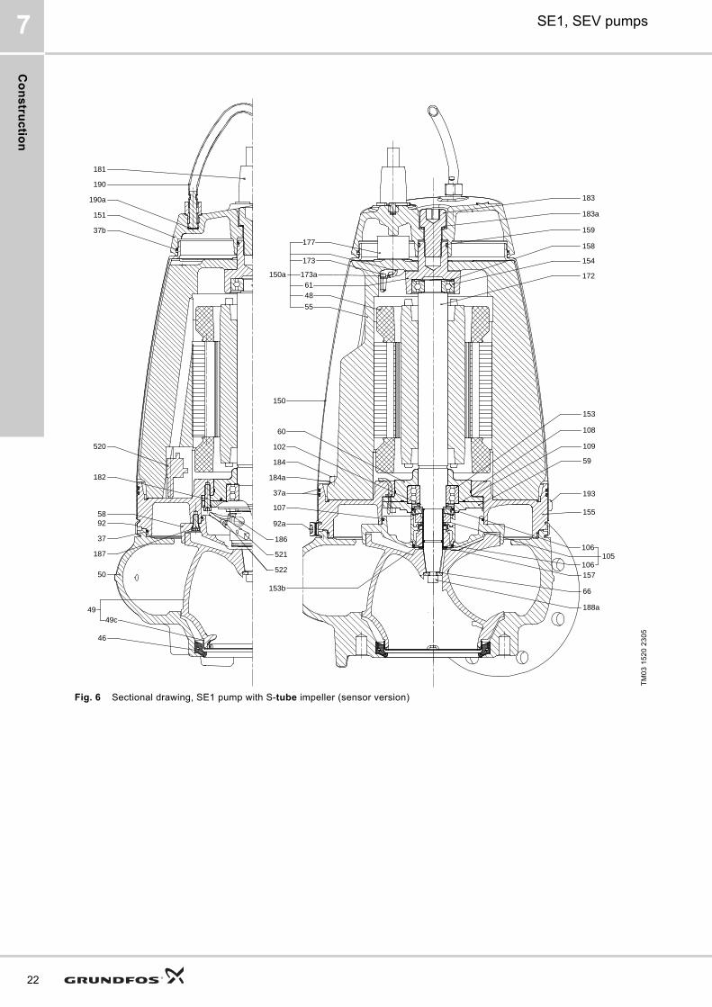
Fig. 6 Sectional drawing, SE1 pump with S-tube impeller (sensor version)
TM
03
15
20
23
05
153b
183
172
154
158
159
183a
106
106105
153
108
59
193
155
157
188a
109
66
60
102
37a
107
92a
150
184a
184
61150a
177
55
48
173a
173
181
190
190a
151
37b
58
50
182
187
37
92
520
186
521
522
46
49c49
Co
ns
tru
cti
on
SE1, SEV pumps 7
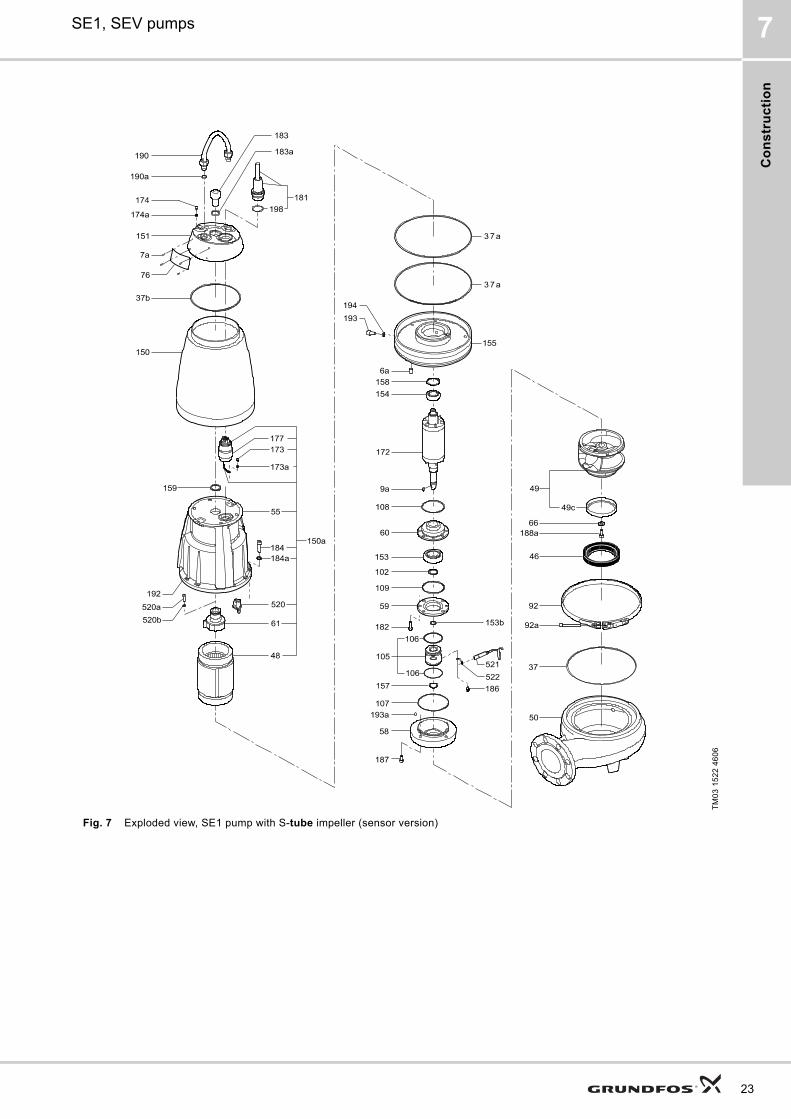
Fig. 7 Exploded view, SE1 pump with S-tube impeller (sensor version)
TM
03
15
22
46
06
23
Co
ns
truc
tion
24
SE1, SEV pumps7
SEV
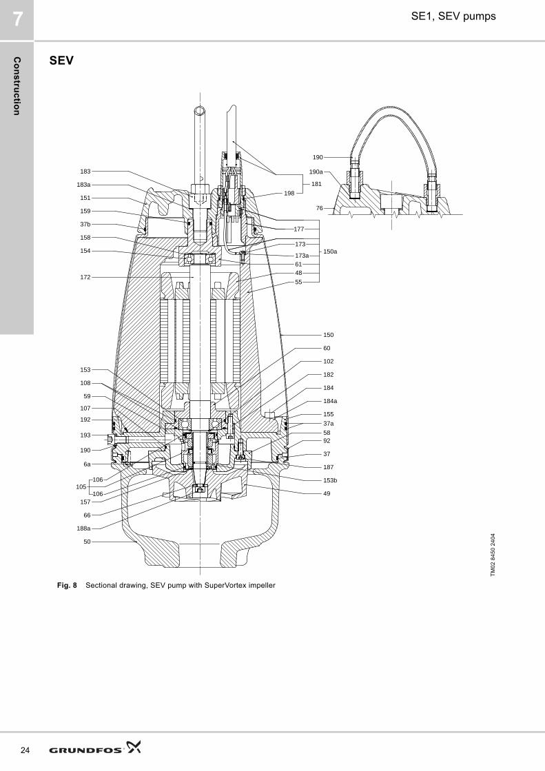
Fig. 8 Sectional drawing, SEV pump with SuperVortex impeller
TM
02
84
50
24
04
190
190a
76
198
181
151
159
37b
183a
183
158
154
172
153
108
107
193
190
157
188a
50
60
102
182
155
37a
92
37
187
153b
59
150
66
184a
184
49
192
58
173
173a
48
55
177
150a
61
105106
106
6a

Co
ns
tru
cti
on
SE1, SEV pumps 7
Fig. 9 Exploded view, SEV pump with SuperVortex impeller
TM
02
84
49
24
04
198
181
190
183
183a
190a
76
7a
151
174a
174
37b
150
159
158
154
172
9a
194
193
6a
108
109
60
153
102
59
182
157
107
193a
58
188
173
173a
55
155
37a
37a
186
184184a
153b
106
106
105
177
61
48
150a66
188a
92
37
92a
49
50
192
25
Co
ns
truc
tion
26
SE1, SEV pumps7
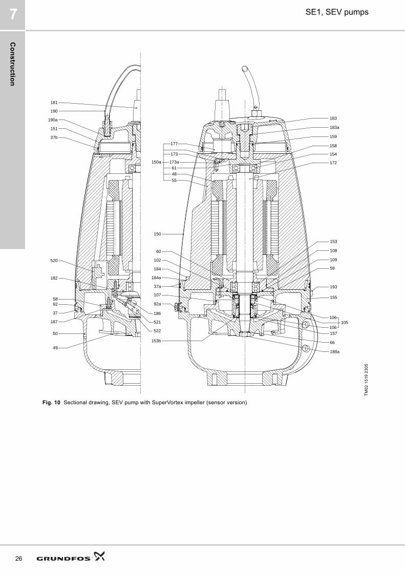
Fig. 10 Sectional drawing, SEV pump with SuperVortex impeller (sensor version)
TM
02
15
19
23
05
173
173a
48
55
177
150a61
184
184a
150
92a
107
37a
102
60
66
109
188a
157
155
193
59
108
153
105106
106
183a
159
158
154
172
183
153b
522
521
520
92
37
187
182
50
58
37b
151
190a
190
181
186
49
Co
ns
tru
cti
on
SE1, SEV pumps 7
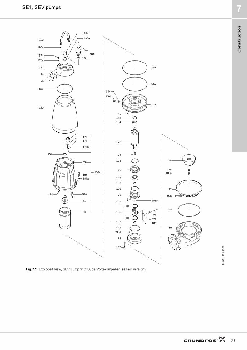
Fig. 11 Exploded view, SEV pump with SuperVortex impeller (sensor version)
TM
02
15
21
23
05
66188a
92
37
92a
49
50
192
198
181
190
183
183a
190a
76
7a
151
174a
174
37b
150
159
158
154
172
9a
194
193
6a
108
109
60
153
102
59
182
157
107
193a
58
187
173
173a
55
155
37a
37a
186
184184a
153b
106
106
105
177
61
48
150a
521
520
522
27
Co
ns
truc
tion
28
SE1, SEV pumps7
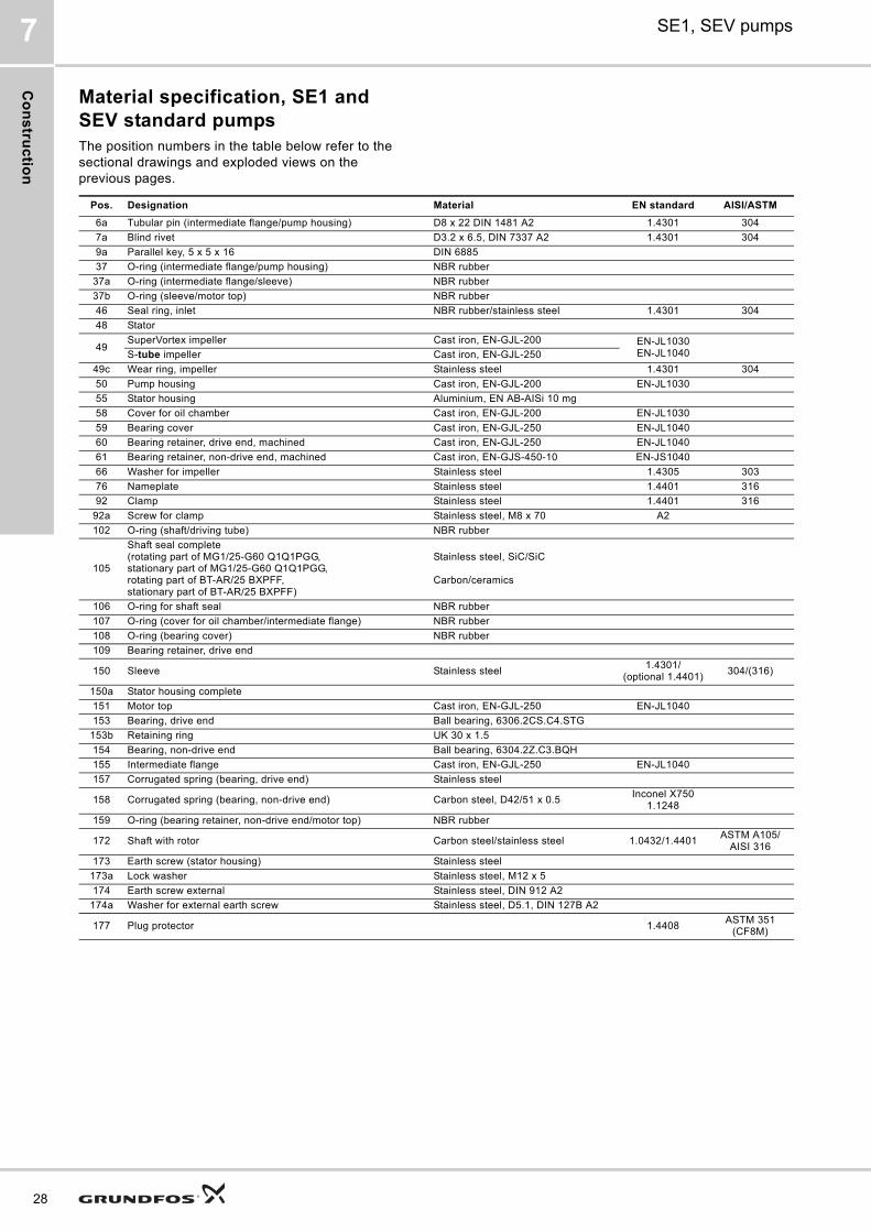
Material specification, SE1 and SEV standard pumpsThe position numbers in the table below refer to the sectional drawings and exploded views on the previous pages.
Pos. Designation Material EN standard AISI/ASTM
6a Tubular pin (intermediate flange/pump housing) D8 x 22 DIN 1481 A2 1.4301 304
7a Blind rivet D3.2 x 6.5, DIN 7337 A2 1.4301 304
9a Parallel key, 5 x 5 x 16 DIN 6885
37 O-ring (intermediate flange/pump housing) NBR rubber
37a O-ring (intermediate flange/sleeve) NBR rubber
37b O-ring (sleeve/motor top) NBR rubber
46 Seal ring, inlet NBR rubber/stainless steel 1.4301 304
48 Stator
49SuperVortex impeller Cast iron, EN-GJL-200 EN-JL1030
EN-JL1040S-tube impeller Cast iron, EN-GJL-250
49c Wear ring, impeller Stainless steel 1.4301 304
50 Pump housing Cast iron, EN-GJL-200 EN-JL1030
55 Stator housing Aluminium, EN AB-AISi 10 mg
58 Cover for oil chamber Cast iron, EN-GJL-200 EN-JL1030
59 Bearing cover Cast iron, EN-GJL-250 EN-JL1040
60 Bearing retainer, drive end, machined Cast iron, EN-GJL-250 EN-JL1040
61 Bearing retainer, non-drive end, machined Cast iron, EN-GJS-450-10 EN-JS1040
66 Washer for impeller Stainless steel 1.4305 303
76 Nameplate Stainless steel 1.4401 316
92 Clamp Stainless steel 1.4401 316
92a Screw for clamp Stainless steel, M8 x 70 A2
102 O-ring (shaft/driving tube) NBR rubber
105
Shaft seal complete(rotating part of MG1/25-G60 Q1Q1PGG, stationary part of MG1/25-G60 Q1Q1PGG, rotating part of BT-AR/25 BXPFF, stationary part of BT-AR/25 BXPFF)
Stainless steel, SiC/SiC
Carbon/ceramics
106 O-ring for shaft seal NBR rubber
107 O-ring (cover for oil chamber/intermediate flange) NBR rubber
108 O-ring (bearing cover) NBR rubber
109 Bearing retainer, drive end
150 Sleeve Stainless steel1.4301/
(optional 1.4401)304/(316)
150a Stator housing complete
151 Motor top Cast iron, EN-GJL-250 EN-JL1040
153 Bearing, drive end Ball bearing, 6306.2CS.C4.STG
153b Retaining ring UK 30 x 1.5
154 Bearing, non-drive end Ball bearing, 6304.2Z.C3.BQH
155 Intermediate flange Cast iron, EN-GJL-250 EN-JL1040
157 Corrugated spring (bearing, drive end) Stainless steel
158 Corrugated spring (bearing, non-drive end) Carbon steel, D42/51 x 0.5Inconel X750
1.1248
159 O-ring (bearing retainer, non-drive end/motor top) NBR rubber
172 Shaft with rotor Carbon steel/stainless steel 1.0432/1.4401ASTM A105/
AISI 316
173 Earth screw (stator housing) Stainless steel
173a Lock washer Stainless steel, M12 x 5
174 Earth screw external Stainless steel, DIN 912 A2
174a Washer for external earth screw Stainless steel, D5.1, DIN 127B A2
177 Plug protector 1.4408ASTM 351
(CF8M)
Co
ns
tru
cti
on
SE1, SEV pumps 7
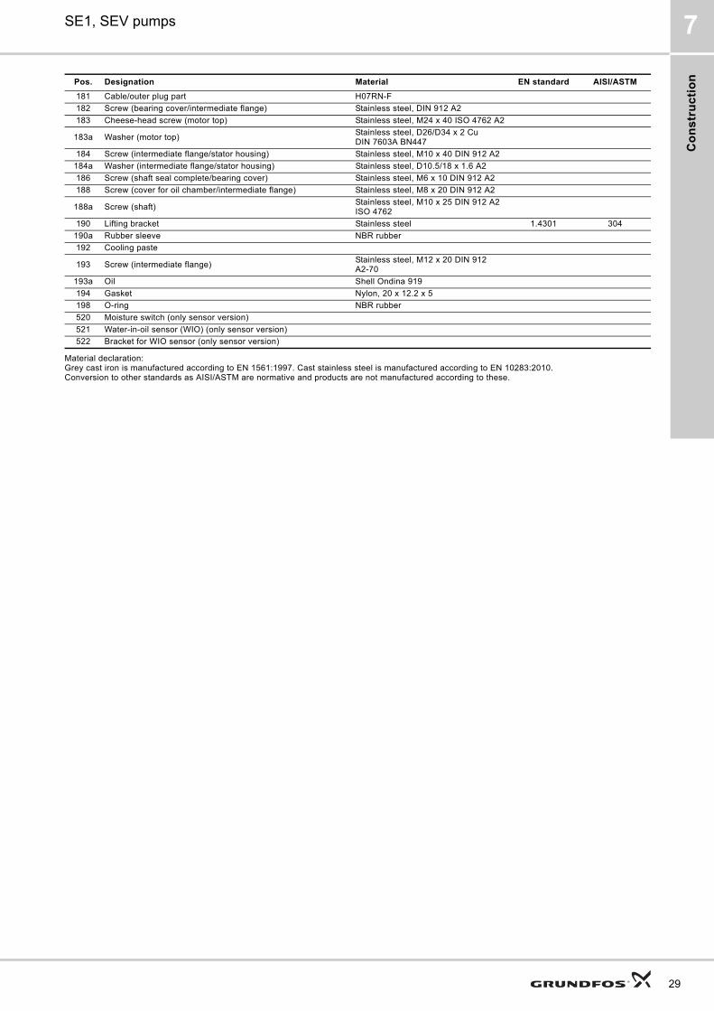
Material declaration:Grey cast iron is manufactured according to EN 1561:1997. Cast stainless steel is manufactured according to EN 10283:2010.Conversion to other standards as AISI/ASTM are normative and products are not manufactured according to these.
181 Cable/outer plug part H07RN-F
182 Screw (bearing cover/intermediate flange) Stainless steel, DIN 912 A2
183 Cheese-head screw (motor top) Stainless steel, M24 x 40 ISO 4762 A2
183a Washer (motor top)Stainless steel, D26/D34 x 2 Cu DIN 7603A BN447
184 Screw (intermediate flange/stator housing) Stainless steel, M10 x 40 DIN 912 A2
184a Washer (intermediate flange/stator housing) Stainless steel, D10.5/18 x 1.6 A2
186 Screw (shaft seal complete/bearing cover) Stainless steel, M6 x 10 DIN 912 A2
188 Screw (cover for oil chamber/intermediate flange) Stainless steel, M8 x 20 DIN 912 A2
188a Screw (shaft)Stainless steel, M10 x 25 DIN 912 A2 ISO 4762
190 Lifting bracket Stainless steel 1.4301 304
190a Rubber sleeve NBR rubber
192 Cooling paste
193 Screw (intermediate flange)Stainless steel, M12 x 20 DIN 912 A2-70
193a Oil Shell Ondina 919
194 Gasket Nylon, 20 x 12.2 x 5
198 O-ring NBR rubber
520 Moisture switch (only sensor version)
521 Water-in-oil sensor (WIO) (only sensor version)
522 Bracket for WIO sensor (only sensor version)
Pos. Designation Material EN standard AISI/ASTM
29
Co
ns
truc
tion
30
SE1, SEV pumps7
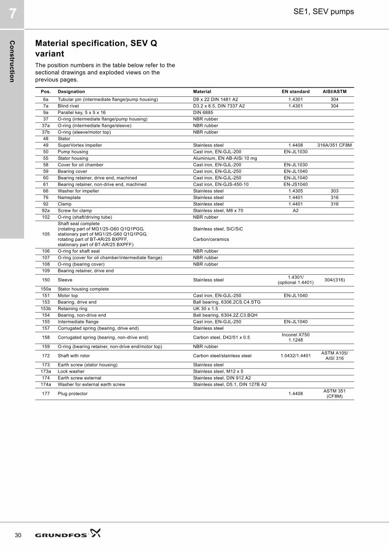
Material specification, SEV Q variant The position numbers in the table below refer to the sectional drawings and exploded views on the previous pages.
Pos. Designation Material EN standard AISI/ASTM
6a Tubular pin (intermediate flange/pump housing) D8 x 22 DIN 1481 A2 1.4301 304
7a Blind rivet D3.2 x 6.5, DIN 7337 A2 1.4301 304
9a Parallel key, 5 x 5 x 16 DIN 6885
37 O-ring (intermediate flange/pump housing) NBR rubber
37a O-ring (intermediate flange/sleeve) NBR rubber
37b O-ring (sleeve/motor top) NBR rubber
48 Stator
49 SuperVortex impeller Stainless steel 1.4408 316A/351 CF8M
50 Pump housing Cast iron, EN-GJL-200 EN-JL1030
55 Stator housing Aluminium, EN AB-AISi 10 mg
58 Cover for oil chamber Cast iron, EN-GJL-200 EN-JL1030
59 Bearing cover Cast iron, EN-GJL-250 EN-JL1040
60 Bearing retainer, drive end, machined Cast iron, EN-GJL-250 EN-JL1040
61 Bearing retainer, non-drive end, machined Cast iron, EN-GJS-450-10 EN-JS1040
66 Washer for impeller Stainless steel 1.4305 303
76 Nameplate Stainless steel 1.4401 316
92 Clamp Stainless steel 1.4401 316
92a Screw for clamp Stainless steel, M8 x 70 A2
102 O-ring (shaft/driving tube) NBR rubber
105
Shaft seal complete(rotating part of MG1/25-G60 Q1Q1PGG, stationary part of MG1/25-G60 Q1Q1PGG, rotating part of BT-AR/25 BXPFF, stationary part of BT-AR/25 BXPFF)
Stainless steel, SiC/SiC
Carbon/ceramics
106 O-ring for shaft seal NBR rubber
107 O-ring (cover for oil chamber/intermediate flange) NBR rubber
108 O-ring (bearing cover) NBR rubber
109 Bearing retainer, drive end
150 Sleeve Stainless steel1.4301/
(optional 1.4401)304/(316)
150a Stator housing complete
151 Motor top Cast iron, EN-GJL-250 EN-JL1040
153 Bearing, drive end Ball bearing, 6306.2CS.C4.STG
153b Retaining ring UK 30 x 1.5
154 Bearing, non-drive end Ball bearing, 6304.2Z.C3.BQH
155 Intermediate flange Cast iron, EN-GJL-250 EN-JL1040
157 Corrugated spring (bearing, drive end) Stainless steel
158 Corrugated spring (bearing, non-drive end) Carbon steel, D42/51 x 0.5Inconel X750
1.1248
159 O-ring (bearing retainer, non-drive end/motor top) NBR rubber
172 Shaft with rotor Carbon steel/stainless steel 1.0432/1.4401ASTM A105/
AISI 316
173 Earth screw (stator housing) Stainless steel
173a Lock washer Stainless steel, M12 x 5
174 Earth screw external Stainless steel, DIN 912 A2
174a Washer for external earth screw Stainless steel, D5.1, DIN 127B A2
177 Plug protector 1.4408ASTM 351
(CF8M)
Co
ns
tru
cti
on
SE1, SEV pumps 7
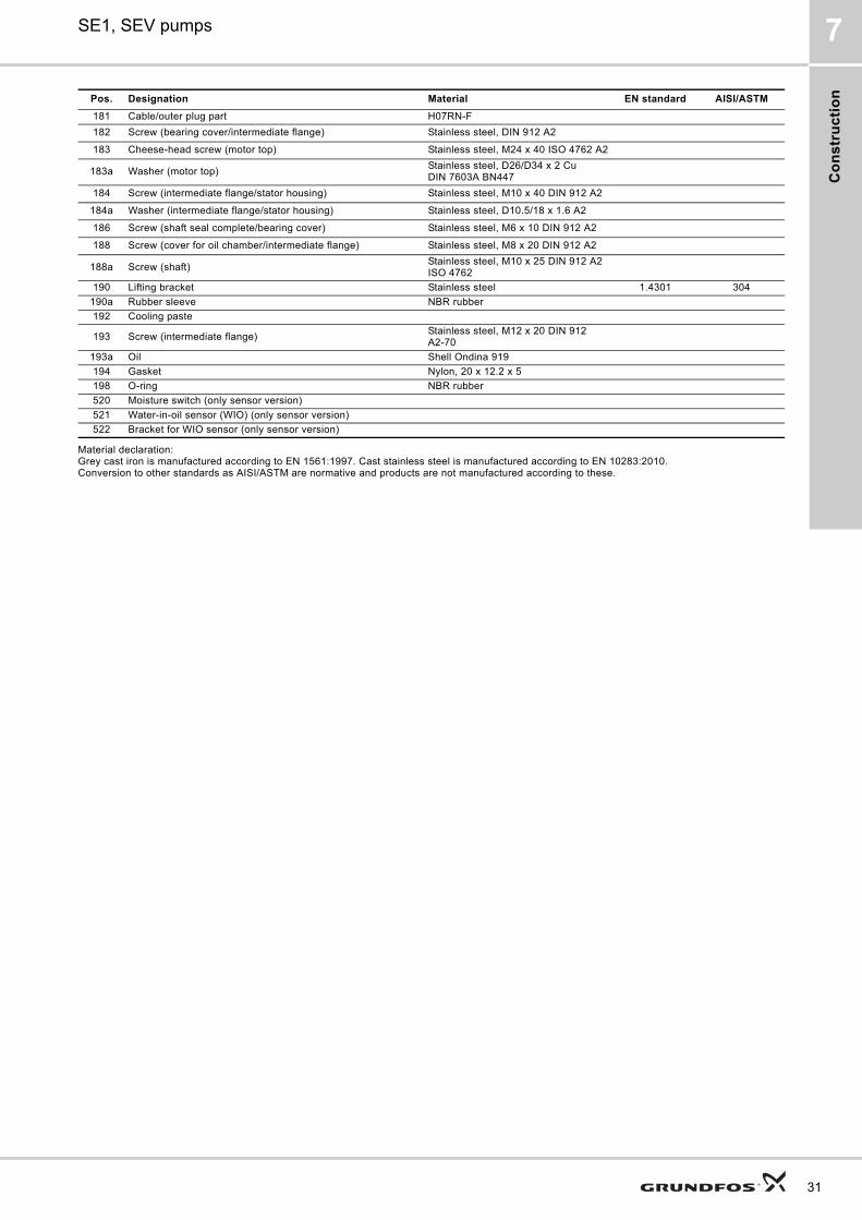
Material declaration:Grey cast iron is manufactured according to EN 1561:1997. Cast stainless steel is manufactured according to EN 10283:2010.Conversion to other standards as AISI/ASTM are normative and products are not manufactured according to these.
181 Cable/outer plug part H07RN-F
182 Screw (bearing cover/intermediate flange) Stainless steel, DIN 912 A2
183 Cheese-head screw (motor top) Stainless steel, M24 x 40 ISO 4762 A2
183a Washer (motor top)Stainless steel, D26/D34 x 2 Cu DIN 7603A BN447
184 Screw (intermediate flange/stator housing) Stainless steel, M10 x 40 DIN 912 A2
184a Washer (intermediate flange/stator housing) Stainless steel, D10.5/18 x 1.6 A2
186 Screw (shaft seal complete/bearing cover) Stainless steel, M6 x 10 DIN 912 A2
188 Screw (cover for oil chamber/intermediate flange) Stainless steel, M8 x 20 DIN 912 A2
188a Screw (shaft)Stainless steel, M10 x 25 DIN 912 A2 ISO 4762
190 Lifting bracket Stainless steel 1.4301 304
190a Rubber sleeve NBR rubber
192 Cooling paste
193 Screw (intermediate flange)Stainless steel, M12 x 20 DIN 912 A2-70
193a Oil Shell Ondina 919
194 Gasket Nylon, 20 x 12.2 x 5
198 O-ring NBR rubber
520 Moisture switch (only sensor version)
521 Water-in-oil sensor (WIO) (only sensor version)
522 Bracket for WIO sensor (only sensor version)
Pos. Designation Material EN standard AISI/ASTM
31
Co
ns
truc
tion
32
SE1, SEV pumps7
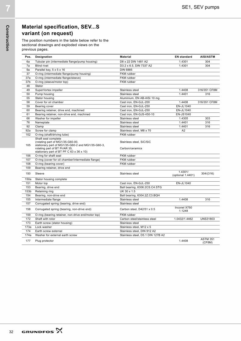
Material specification, SEV...S variant (on request)The position numbers in the table below refer to the sectional drawings and exploded views on the previous pages.
Pos. Designation Material EN standard AISI/ASTM
6a Tubular pin (intermediate flange/pump housing) D8 x 22 DIN 1481 A2 1.4301 304
7a Blind rivet D3.2 x 6.5, DIN 7337 A2 1.4301 304
9a Parallel key, 5 x 5 x 16 DIN 6885
37 O-ring (intermediate flange/pump housing) FKM rubber
37a O-ring (intermediate flange/sleeve) FKM rubber
37b O-ring (sleeve/motor top) FKM rubber
48 Stator
49 SuperVortex impeller Stainless steel 1.4408 316/351 CF8M
50 Pump housing Stainless steel 1.4401 316
55 Stator housing Aluminium, EN AB-AISi 10 mg
58 Cover for oil chamber Cast iron, EN-GJL-200 1.4408 316/351 CF8M
59 Bearing cover Cast iron, EN-GJL-250 EN-JL1040
60 Bearing retainer, drive end, machined Cast iron, EN-GJL-250 EN-JL1040
61 Bearing retainer, non-drive end, machined Cast iron, EN-GJS-450-10 EN-JS1040
66 Washer for impeller Stainless steel 1.4305 303
76 Nameplate Stainless steel 1.4401 316
92 Clamp Stainless steel 1.4401 316
92a Screw for clamp Stainless steel, M8 x 70 A2
102 O-ring (shaft/driving tube) FKM rubber
105
Shaft seal complete (rotating part of MG1/35-G60-00, stationary part of MG1/35-G60-2 and MG1/35-G60-3, rotating part of BT Pr/AR 35, stationary part of BT PF C 63 x 36 x 10)
Stainless steel, SiC/SiC
Carbon/ceramics
106 O-ring for shaft seal FKM rubber
107 O-ring (cover for oil chamber/intermediate flange) FKM rubber
108 O-ring (bearing cover) FKM rubber
109 Bearing retainer, drive end
150 Sleeve Stainless steel1.4301/
(optional 1.4401)304/(316)
150a Stator housing complete
151 Motor top Cast iron, EN-GJL-250 EN-JL1040
153 Bearing, drive end Ball bearing, 6306.2CS.C4.STG
153b Retaining ring UK 30 x 1.5
154 Bearing, non-drive end Ball bearing, 6304.2Z.C3.BQH
155 Intermediate flange Stainless steel 1.4408 316
157 Corrugated spring (bearing, drive end) Stainless steel
158 Corrugated spring (bearing, non-drive end) Carbon steel, D42/51 x 0.5Inconel X750
1.1248
159 O-ring (bearing retainer, non-drive end/motor top) FKM rubber
172 Shaft with rotor Carbon steel/stainless steel 1.0432/1.4462 UNS31803
173 Earth screw (stator housing) Stainless steel
173a Lock washer Stainless steel, M12 x 5
174 Earth screw external Stainless steel, DIN 912 A2
174a Washer for external earth screw Stainless steel, D5.1 DIN 127B A2
177 Plug protector 1.4408ASTM 351
(CF8M)

Co
ns
tru
cti
on
SE1, SEV pumps 7
Material declaration:Grey cast iron is manufactured according to EN 1561:1997. Cast stainless steel is manufactured according to EN 10283:2010.Conversion to other standards as AISI/ASTM are normative and products are not manufactured according to these.
181 Cable/outer plug part H07RN-F
182 Screw (bearing cover/intermediate flange) Stainless steel, DIN 912 A2
183 Cheese-head screw (motor top) Stainless steel, M24 x 40 ISO 4762 A2
183a Washer (motor top)Stainless steel, D26/D34 x 2 Cu DIN 7603A BN447
184 Screw (intermediate flange/stator housing) Stainless steel, M10 x 40 DIN 912 A2
184a Washer (intermediate flange/stator housing) Stainless steel, D10.5/18 x 1.6 A2
186 Screw (shaft seal complete/bearing cover) Stainless steel, M6 x 10 DIN 912 A2
188 Screw (cover for oil chamber/intermediate flange) Stainless steel, M8 x 20 DIN 912 A2
188a Screw (shaft)Stainless steel, M10 x 25 DIN 912 A2 ISO 4762
190 Lifting bracket Stainless steel 1.4401 316
190a Rubber sleeve FKM rubber
192 Cooling paste
193 Screw (intermediate flange)Stainless steel, M12 x 20 DIN 912 A2-70
193a Oil Shell Ondina 919
194 Gasket Nylon, 20 x 12.2 x 5
198 O-ring FKM rubber
520 Moisture switch (only sensor version)
521 Water-in-oil sensor (WIO) (only sensor version)
522 Bracket for WIO sensor (only sensor version)
Pos. Designation Material EN standard AISI/ASTM
33
Co
ns
truc
tion
34
SE1, SEV pumps7
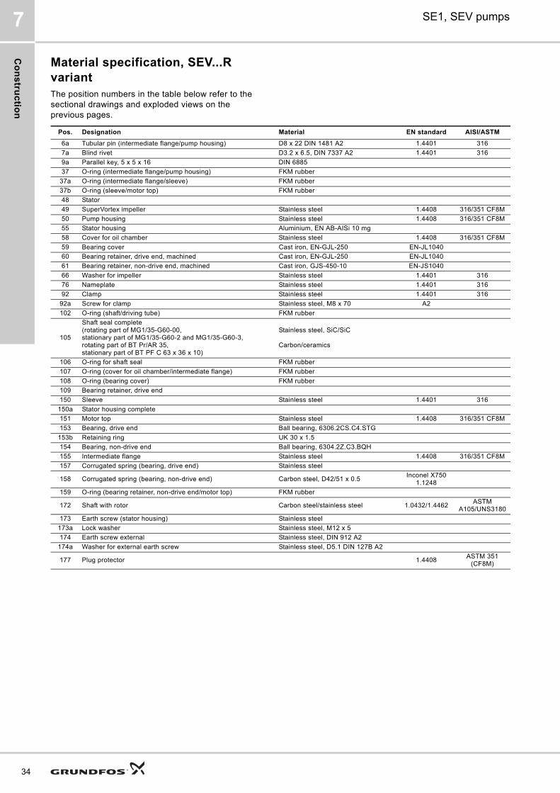
Material specification, SEV...R variantThe position numbers in the table below refer to the sectional drawings and exploded views on the previous pages.
Pos. Designation Material EN standard AISI/ASTM
6a Tubular pin (intermediate flange/pump housing) D8 x 22 DIN 1481 A2 1.4401 316
7a Blind rivet D3.2 x 6.5, DIN 7337 A2 1.4401 316
9a Parallel key, 5 x 5 x 16 DIN 6885
37 O-ring (intermediate flange/pump housing) FKM rubber
37a O-ring (intermediate flange/sleeve) FKM rubber
37b O-ring (sleeve/motor top) FKM rubber
48 Stator
49 SuperVortex impeller Stainless steel 1.4408 316/351 CF8M
50 Pump housing Stainless steel 1.4408 316/351 CF8M
55 Stator housing Aluminium, EN AB-AISi 10 mg
58 Cover for oil chamber Stainless steel 1.4408 316/351 CF8M
59 Bearing cover Cast iron, EN-GJL-250 EN-JL1040
60 Bearing retainer, drive end, machined Cast iron, EN-GJL-250 EN-JL1040
61 Bearing retainer, non-drive end, machined Cast iron, GJS-450-10 EN-JS1040
66 Washer for impeller Stainless steel 1.4401 316
76 Nameplate Stainless steel 1.4401 316
92 Clamp Stainless steel 1.4401 316
92a Screw for clamp Stainless steel, M8 x 70 A2
102 O-ring (shaft/driving tube) FKM rubber
105
Shaft seal complete(rotating part of MG1/35-G60-00, stationary part of MG1/35-G60-2 and MG1/35-G60-3, rotating part of BT Pr/AR 35, stationary part of BT PF C 63 x 36 x 10)
Stainless steel, SiC/SiC
Carbon/ceramics
106 O-ring for shaft seal FKM rubber
107 O-ring (cover for oil chamber/intermediate flange) FKM rubber
108 O-ring (bearing cover) FKM rubber
109 Bearing retainer, drive end
150 Sleeve Stainless steel 1.4401 316
150a Stator housing complete
151 Motor top Stainless steel 1.4408 316/351 CF8M
153 Bearing, drive end Ball bearing, 6306.2CS.C4.STG
153b Retaining ring UK 30 x 1.5
154 Bearing, non-drive end Ball bearing, 6304.2Z.C3.BQH
155 Intermediate flange Stainless steel 1.4408 316/351 CF8M
157 Corrugated spring (bearing, drive end) Stainless steel
158 Corrugated spring (bearing, non-drive end) Carbon steel, D42/51 x 0.5Inconel X750
1.1248
159 O-ring (bearing retainer, non-drive end/motor top) FKM rubber
172 Shaft with rotor Carbon steel/stainless steel 1.0432/1.4462ASTM
A105/UNS3180
173 Earth screw (stator housing) Stainless steel
173a Lock washer Stainless steel, M12 x 5
174 Earth screw external Stainless steel, DIN 912 A2
174a Washer for external earth screw Stainless steel, D5.1 DIN 127B A2
177 Plug protector 1.4408ASTM 351
(CF8M)

Co
ns
tru
cti
on
SE1, SEV pumps 7
Material declaration:Grey cast iron is manufactured according to EN 1561:1997. Cast stainless steel is manufactured according to EN 10283:2010.Conversion to other standards as AISI/ASTM are normative and products are not manufactured according to these.
181 Cable/outer plug part H07RN-F
182 Screw (bearing cover/intermediate flange) Stainless steel, DIN 912 A2
183 Cheese-head screw (motor top) Stainless steel, M24 x 40 ISO 4762 A2
183a Washer (motor top)Stainless steel, D26/D34 x 2 Cu DIN 7603A BN447
184 Screw (intermediate flange/stator housing) Stainless steel, M10 x 40 DIN 912 A2
184a Washer (intermediate flange/stator housing) Stainless steel, D10.5/18 x 1.6 A2
186 Screw (shaft seal complete/bearing cover) Stainless steel, M6 x 10 DIN 912 A2
188 Screw (cover for oil chamber/intermediate flange) Stainless steel, M8 x 20 DIN 912 A2
188a Screw (shaft)Stainless steel, M10 x 25 DIN 912 A2 ISO 4762
190 Lifting bracket Stainless steel 1.4401 316
190a Rubber sleeve FKM rubber
192 Cooling paste
193 Screw (intermediate flange)Stainless steel, M12 x 20 DIN 912 A2-70
193a Oil Shell Ondina 919
194 Gasket Nylon, 20 x 12.2 x 5
198 O-ring FKM rubber
520 Moisture switch (only sensor version)
521 Water-in-oil sensor (WIO) (only sensor version)
522 Bracket for WIO sensor (only sensor version)
Pos. Designation Material EN standard AISI/ASTM
35
Co
ns
truc
tion
36
SE1, SEV pumps7
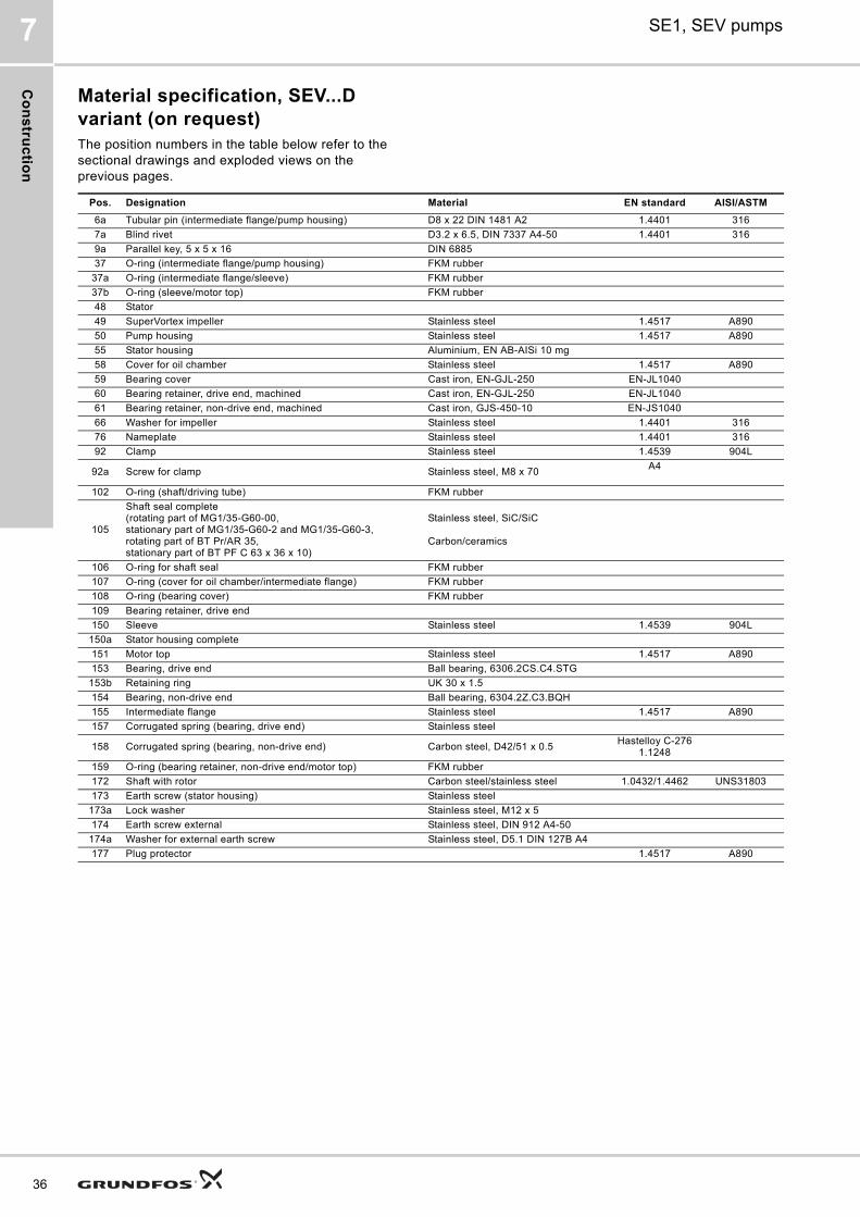
Material specification, SEV...D variant (on request)The position numbers in the table below refer to the sectional drawings and exploded views on the previous pages.
Pos. Designation Material EN standard AISI/ASTM
6a Tubular pin (intermediate flange/pump housing) D8 x 22 DIN 1481 A2 1.4401 316
7a Blind rivet D3.2 x 6.5, DIN 7337 A4-50 1.4401 316
9a Parallel key, 5 x 5 x 16 DIN 6885
37 O-ring (intermediate flange/pump housing) FKM rubber
37a O-ring (intermediate flange/sleeve) FKM rubber
37b O-ring (sleeve/motor top) FKM rubber
48 Stator
49 SuperVortex impeller Stainless steel 1.4517 A890
50 Pump housing Stainless steel 1.4517 A890
55 Stator housing Aluminium, EN AB-AISi 10 mg
58 Cover for oil chamber Stainless steel 1.4517 A890
59 Bearing cover Cast iron, EN-GJL-250 EN-JL1040
60 Bearing retainer, drive end, machined Cast iron, EN-GJL-250 EN-JL1040
61 Bearing retainer, non-drive end, machined Cast iron, GJS-450-10 EN-JS1040
66 Washer for impeller Stainless steel 1.4401 316
76 Nameplate Stainless steel 1.4401 316
92 Clamp Stainless steel 1.4539 904L
92a Screw for clamp Stainless steel, M8 x 70A4
102 O-ring (shaft/driving tube) FKM rubber
105
Shaft seal complete(rotating part of MG1/35-G60-00, stationary part of MG1/35-G60-2 and MG1/35-G60-3, rotating part of BT Pr/AR 35, stationary part of BT PF C 63 x 36 x 10)
Stainless steel, SiC/SiC
Carbon/ceramics
106 O-ring for shaft seal FKM rubber
107 O-ring (cover for oil chamber/intermediate flange) FKM rubber
108 O-ring (bearing cover) FKM rubber
109 Bearing retainer, drive end
150 Sleeve Stainless steel 1.4539 904L
150a Stator housing complete
151 Motor top Stainless steel 1.4517 A890
153 Bearing, drive end Ball bearing, 6306.2CS.C4.STG
153b Retaining ring UK 30 x 1.5
154 Bearing, non-drive end Ball bearing, 6304.2Z.C3.BQH
155 Intermediate flange Stainless steel 1.4517 A890
157 Corrugated spring (bearing, drive end) Stainless steel
158 Corrugated spring (bearing, non-drive end) Carbon steel, D42/51 x 0.5Hastelloy C-276
1.1248
159 O-ring (bearing retainer, non-drive end/motor top) FKM rubber
172 Shaft with rotor Carbon steel/stainless steel 1.0432/1.4462 UNS31803
173 Earth screw (stator housing) Stainless steel
173a Lock washer Stainless steel, M12 x 5
174 Earth screw external Stainless steel, DIN 912 A4-50
174a Washer for external earth screw Stainless steel, D5.1 DIN 127B A4
177 Plug protector 1.4517 A890
Co
ns
tru
cti
on
SE1, SEV pumps 7
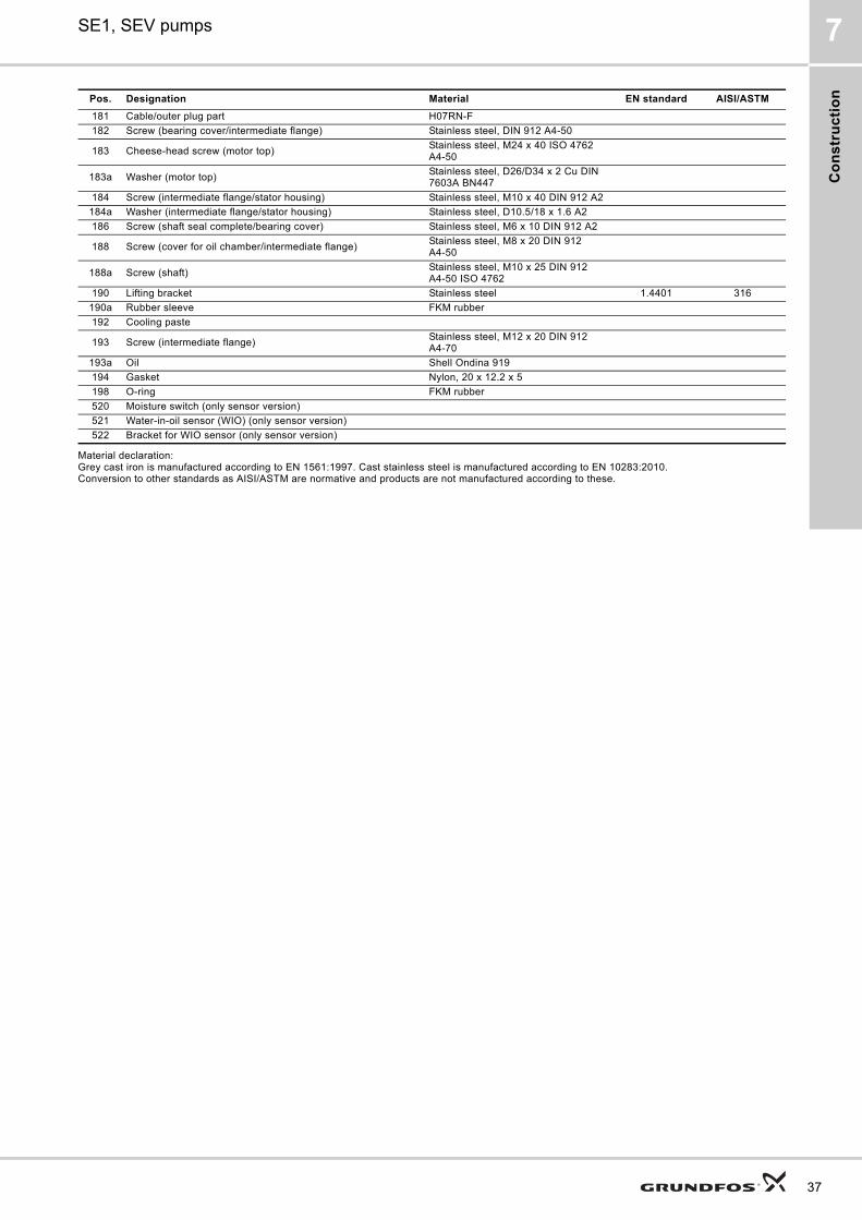
Material declaration:Grey cast iron is manufactured according to EN 1561:1997. Cast stainless steel is manufactured according to EN 10283:2010.Conversion to other standards as AISI/ASTM are normative and products are not manufactured according to these.
181 Cable/outer plug part H07RN-F
182 Screw (bearing cover/intermediate flange) Stainless steel, DIN 912 A4-50
183 Cheese-head screw (motor top)Stainless steel, M24 x 40 ISO 4762 A4-50
183a Washer (motor top)Stainless steel, D26/D34 x 2 Cu DIN 7603A BN447
184 Screw (intermediate flange/stator housing) Stainless steel, M10 x 40 DIN 912 A2
184a Washer (intermediate flange/stator housing) Stainless steel, D10.5/18 x 1.6 A2
186 Screw (shaft seal complete/bearing cover) Stainless steel, M6 x 10 DIN 912 A2
188 Screw (cover for oil chamber/intermediate flange)Stainless steel, M8 x 20 DIN 912 A4-50
188a Screw (shaft)Stainless steel, M10 x 25 DIN 912 A4-50 ISO 4762
190 Lifting bracket Stainless steel 1.4401 316
190a Rubber sleeve FKM rubber
192 Cooling paste
193 Screw (intermediate flange)Stainless steel, M12 x 20 DIN 912 A4-70
193a Oil Shell Ondina 919
194 Gasket Nylon, 20 x 12.2 x 5
198 O-ring FKM rubber
520 Moisture switch (only sensor version)
521 Water-in-oil sensor (WIO) (only sensor version)
522 Bracket for WIO sensor (only sensor version)
Pos. Designation Material EN standard AISI/ASTM
37
Pro
du
ct d
es
crip
tion
38
SE1, SEV pumps8
8. Product description
Features
Ball bearings
The ball bearings are greased for life.
Main bearings: Double-row angular contact ball bearing.
Support bearings: Single-row deep-groove ball bearing.
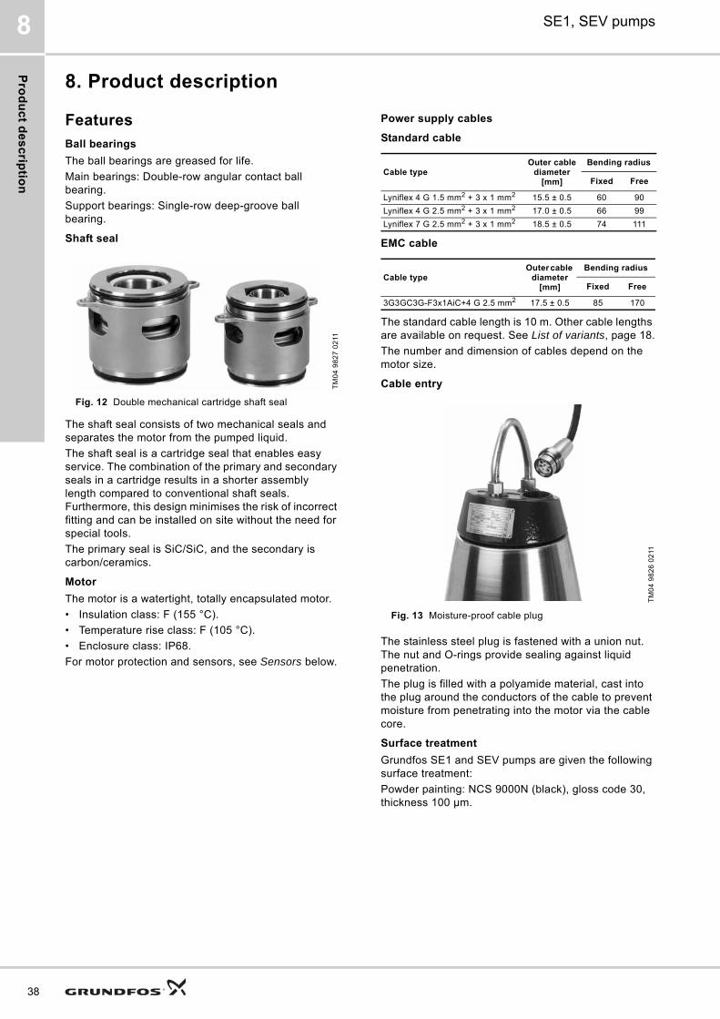
Shaft seal
Fig. 12 Double mechanical cartridge shaft seal
The shaft seal consists of two mechanical seals and separates the motor from the pumped liquid.
The shaft seal is a cartridge seal that enables easy service. The combination of the primary and secondary seals in a cartridge results in a shorter assembly length compared to conventional shaft seals. Furthermore, this design minimises the risk of incorrect fitting and can be installed on site without the need for special tools.
The primary seal is SiC/SiC, and the secondary is carbon/ceramics.
Motor
The motor is a watertight, totally encapsulated motor.
• Insulation class: F (155 °C).
• Temperature rise class: F (105 °C).
• Enclosure class: IP68.
For motor protection and sensors, see Sensors below.
Power supply cables
Standard cable
EMC cable
The standard cable length is 10 m. Other cable lengths are available on request. See List of variants, page 18.
The number and dimension of cables depend on the motor size.
Cable entry
Fig. 13 Moisture-proof cable plug
The stainless steel plug is fastened with a union nut. The nut and O-rings provide sealing against liquid penetration.
The plug is filled with a polyamide material, cast into the plug around the conductors of the cable to prevent moisture from penetrating into the motor via the cable core.
Surface treatment
Grundfos SE1 and SEV pumps are given the following surface treatment:
Powder painting: NCS 9000N (black), gloss code 30, thickness 100 μm.
TM
04
98
27
02
11
Cable type Outer cable
diameter[mm]
Bending radius
Fixed Free
Lyniflex 4 G 1.5 mm2 + 3 x 1 mm2 15.5 ± 0.5 60 90
Lyniflex 4 G 2.5 mm2 + 3 x 1 mm2 17.0 ± 0.5 66 99
Lyniflex 7 G 2.5 mm2 + 3 x 1 mm2 18.5 ± 0.5 74 111
Cable typeOuter cable
diameter[mm]
Bending radius
Fixed Free
3G3GC3G-F3x1AiC+4 G 2.5 mm2 17.5 ± 0.5 85 170
TM
04
98
26
02
11
Pro
du
ct
de
sc
rip
tio
n
SE1, SEV pumps 8
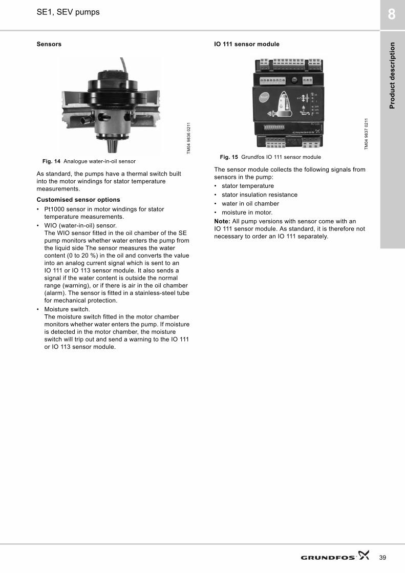
Sensors
Fig. 14 Analogue water-in-oil sensor
As standard, the pumps have a thermal switch built into the motor windings for stator temperature measurements.
Customised sensor options
• Pt1000 sensor in motor windings for stator temperature measurements.
• WIO (water-in-oil) sensor.The WIO sensor fitted in the oil chamber of the SE pump monitors whether water enters the pump from the liquid side The sensor measures the water content (0 to 20 %) in the oil and converts the value into an analog current signal which is sent to an IO 111 or IO 113 sensor module. It also sends a signal if the water content is outside the normal range (warning), or if there is air in the oil chamber (alarm). The sensor is fitted in a stainless-steel tube for mechanical protection.
• Moisture switch.The moisture switch fitted in the motor chamber monitors whether water enters the pump. If moisture is detected in the motor chamber, the moisture switch will trip out and send a warning to the IO 111 or IO 113 sensor module.
IO 111 sensor module
Fig. 15 Grundfos IO 111 sensor module
The sensor module collects the following signals from sensors in the pump:
• stator temperature
• stator insulation resistance
• water in oil chamber
• moisture in motor.
Note: All pump versions with sensor come with an IO 111 sensor module. As standard, it is therefore not necessary to order an IO 111 separately.
TM
04
98
36
02
11
TM
04
98
37
02
11
39
Pro
du
ct d
es
crip
tion
40
SE1, SEV pumps8
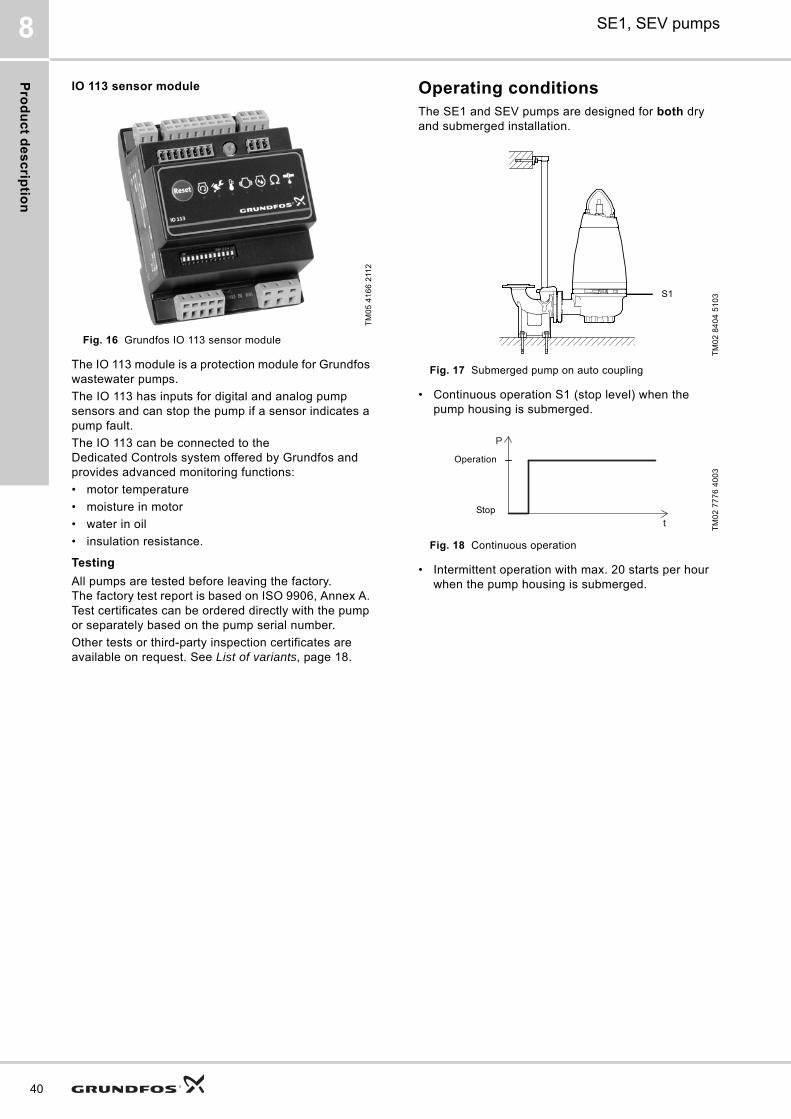
IO 113 sensor module
Fig. 16 Grundfos IO 113 sensor module
The IO 113 module is a protection module for Grundfos wastewater pumps.
The IO 113 has inputs for digital and analog pump sensors and can stop the pump if a sensor indicates a pump fault.
The IO 113 can be connected to the Dedicated Controls system offered by Grundfos and provides advanced monitoring functions:
• motor temperature
• moisture in motor
• water in oil
• insulation resistance.
Testing
All pumps are tested before leaving the factory. The factory test report is based on ISO 9906, Annex A. Test certificates can be ordered directly with the pump or separately based on the pump serial number.
Other tests or third-party inspection certificates are available on request. See List of variants, page 18.
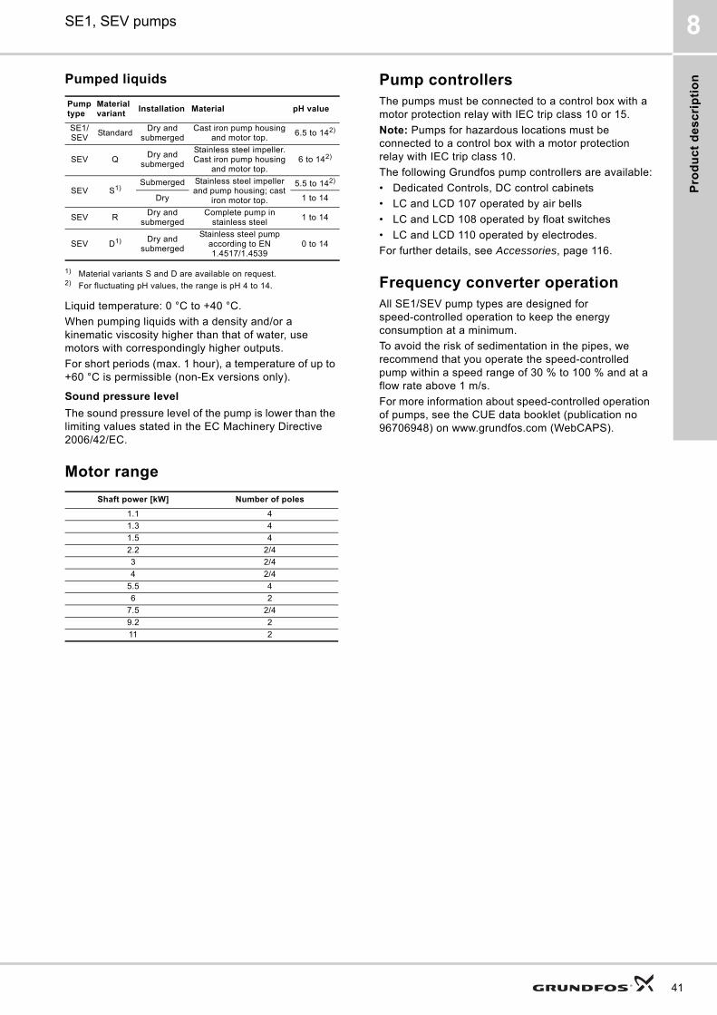
Operating conditionsThe SE1 and SEV pumps are designed for both dry and submerged installation.
Fig. 17 Submerged pump on auto coupling
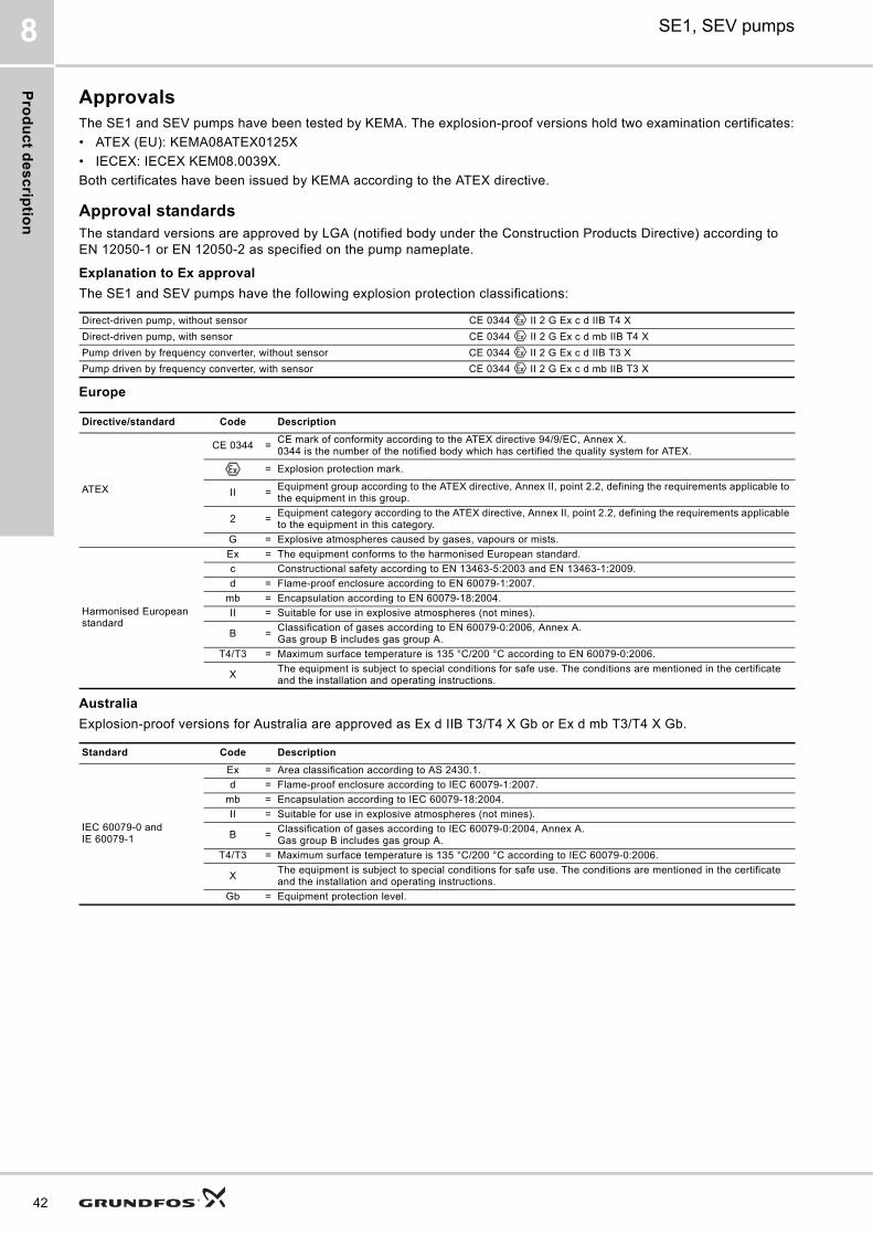
• Continuous operation S1 (stop level) when the pump housing is submerged.
Fig. 18 Continuous operation
• Intermittent operation with max. 20 starts per hour when the pump housing is submerged.
TM
05
41
66
211
2
TM
02
84
04
51
03
TM
02
77
76
40
03
S1
P
t
Operation
Stop
Pro
du
ct
de
sc
rip
tio
n
SE1, SEV pumps 8
Pumped liquids
1) Material variants S and D are available on request.2) For fluctuating pH values, the range is pH 4 to 14.
Liquid temperature: 0 °C to +40 °C.
When pumping liquids with a density and/or a kinematic viscosity higher than that of water, use motors with correspondingly higher outputs.
For short periods (max. 1 hour), a temperature of up to +60 °C is permissible (non-Ex versions only).
Sound pressure level
The sound pressure level of the pump is lower than the limiting values stated in the EC Machinery Directive 2006/42/EC.
Motor range
Pump controllersThe pumps must be connected to a control box with a motor protection relay with IEC trip class 10 or 15.
Note: Pumps for hazardous locations must be connected to a control box with a motor protection relay with IEC trip class 10.
The following Grundfos pump controllers are available:
• Dedicated Controls, DC control cabinets
• LC and LCD 107 operated by air bells
• LC and LCD 108 operated by float switches
• LC and LCD 110 operated by electrodes.
For further details, see Accessories, page 116.
Frequency converter operationAll SE1/SEV pump types are designed for speed-controlled operation to keep the energy consumption at a minimum.
To avoid the risk of sedimentation in the pipes, we recommend that you operate the speed-controlled pump within a speed range of 30 % to 100 % and at a flow rate above 1 m/s.
For more information about speed-controlled operation of pumps, see the CUE data booklet (publication no 96706948) on www.grundfos.com (WebCAPS).
Pump type
Material variant
Installation Material pH value
SE1/SEV
StandardDry and
submergedCast iron pump housing
and motor top.6.5 to 142)
SEV QDry and
submerged
Stainless steel impeller. Cast iron pump housing
and motor top.6 to 142)
SEV S1)Submerged Stainless steel impeller
and pump housing; cast iron motor top.
5.5 to 142)
Dry 1 to 14
SEV RDry and
submergedComplete pump in
stainless steel1 to 14
SEV D1) Dry and submerged
Stainless steel pump according to EN 1.4517/1.4539
0 to 14
Shaft power [kW] Number of poles
1.1 4
1.3 4
1.5 4
2.2 2/4
3 2/4
4 2/4
5.5 4
6 2
7.5 2/4
9.2 2
11 2
41
Pro
du
ct d
es
crip
tion
42
SE1, SEV pumps8
ApprovalsThe SE1 and SEV pumps have been tested by KEMA. The explosion-proof versions hold two examination certificates:
• ATEX (EU): KEMA08ATEX0125X
• IECEX: IECEX KEM08.0039X.
Both certificates have been issued by KEMA according to the ATEX directive.
Approval standardsThe standard versions are approved by LGA (notified body under the Construction Products Directive) according to EN 12050-1 or EN 12050-2 as specified on the pump nameplate.
Explanation to Ex approval
The SE1 and SEV pumps have the following explosion protection classifications:
Europe
Australia
Explosion-proof versions for Australia are approved as Ex d IIB T3/T4 X Gb or Ex d mb T3/T4 X Gb.
Direct-driven pump, without sensor CE 0344 II 2 G Ex c d IIB T4 X
Direct-driven pump, with sensor CE 0344 II 2 G Ex c d mb IIB T4 X
Pump driven by frequency converter, without sensor CE 0344 II 2 G Ex c d IIB T3 X
Pump driven by frequency converter, with sensor CE 0344 II 2 G Ex c d mb IIB T3 X
Directive/standard Code Description
ATEX
CE 0344 =CE mark of conformity according to the ATEX directive 94/9/EC, Annex X. 0344 is the number of the notified body which has certified the quality system for ATEX.
= Explosion protection mark.
II =Equipment group according to the ATEX directive, Annex II, point 2.2, defining the requirements applicable to the equipment in this group.
2 =Equipment category according to the ATEX directive, Annex II, point 2.2, defining the requirements applicable to the equipment in this category.
G = Explosive atmospheres caused by gases, vapours or mists.
Harmonised European standard
Ex = The equipment conforms to the harmonised European standard.
c Constructional safety according to EN 13463-5:2003 and EN 13463-1:2009.
d = Flame-proof enclosure according to EN 60079-1:2007.
mb = Encapsulation according to EN 60079-18:2004.
II = Suitable for use in explosive atmospheres (not mines).
B =Classification of gases according to EN 60079-0:2006, Annex A. Gas group B includes gas group A.
T4/T3 = Maximum surface temperature is 135 °C/200 °C according to EN 60079-0:2006.
XThe equipment is subject to special conditions for safe use. The conditions are mentioned in the certificate and the installation and operating instructions.
Standard Code Description
IEC 60079-0 andIE 60079-1
Ex = Area classification according to AS 2430.1.
d = Flame-proof enclosure according to IEC 60079-1:2007.
mb = Encapsulation according to IEC 60079-18:2004.
II = Suitable for use in explosive atmospheres (not mines).
B =Classification of gases according to IEC 60079-0:2004, Annex A. Gas group B includes gas group A.
T4/T3 = Maximum surface temperature is 135 °C/200 °C according to IEC 60079-0:2006.
XThe equipment is subject to special conditions for safe use. The conditions are mentioned in the certificate and the installation and operating instructions.
Gb = Equipment protection level.
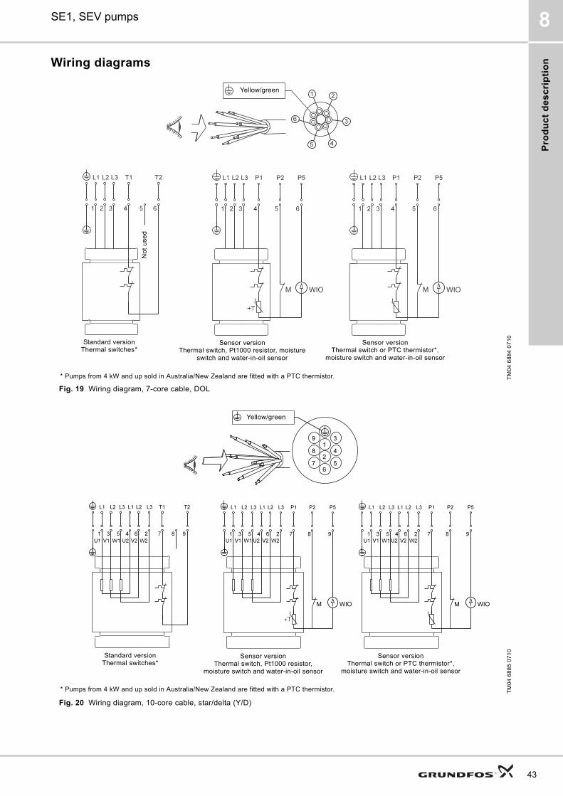
Pro
du
ct
de
sc
rip
tio
n
SE1, SEV pumps 8
Wiring diagrams
Fig. 19 Wiring diagram, 7-core cable, DOL
Fig. 20 Wiring diagram, 10-core cable, star/delta (Y/D)
TM
04
68
84
07
10
Standard versionThermal switches*
Sensor versionThermal switch, Pt1000 resistor, moisture
switch and water-in-oil sensor
Sensor versionThermal switch or PTC thermistor*,
moisture switch and water-in-oil sensor
Yellow/green
No
t u
sed
* Pumps from 4 kW and up sold in Australia/New Zealand are fitted with a PTC thermistor.
TM
04
68
85
07
10
Yellow/green
Standard versionThermal switches*
Sensor versionThermal switch, Pt1000 resistor,
moisture switch and water-in-oil sensor
Sensor versionThermal switch or PTC thermistor*,
moisture switch and water-in-oil sensor
* Pumps from 4 kW and up sold in Australia/New Zealand are fitted with a PTC thermistor.
43
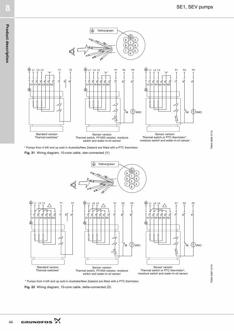
Pro
du
ct d
es
crip
tion
44
SE1, SEV pumps8
Fig. 21 Wiring diagram, 10-core cable, star-connected (Y)
Fig. 22 Wiring diagram, 10-core cable, delta-connected (D)
TM
04
68
86
07
10
Yellow/green
Standard versionThermal switches*
Sensor versionThermal switch, Pt1000 resistor, moisture
switch and water-in-oil sensor
Sensor versionThermal switch or PTC thermistor*,
moisture switch and water-in-oil sensor
* Pumps from 4 kW and up sold in Australia/New Zealand are fitted with a PTC thermistor.
TM
04
68
87
07
10
Yellow/green
Standard versionThermal switches*
Sensor versionThermal switch, Pt1000 resistor, moisture
switch and water-in-oil sensor
Sensor versionThermal switch or PTC thermistor*,
moisture switch and water-in-oil sensor
* Pumps from 4 kW and up sold in Australia/New Zealand are fitted with a PTC thermistor.
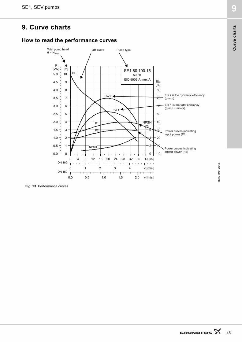
Cu
rve
ch
art
s
SE1, SEV pumps 9
9. Curve charts
How to read the performance curves
Fig. 23 Performance curves
TM
02
79
61
20
12
0 4 8 12 16 20 24 28 32 36 Q [l/s]
0
1
2
3
4
5
6
7
8
9
10
[m]H
0 1 2 3 4 v [m/s]
0
10
20
30
40
50
60
70
80
[%]Eta
0.0 0.5 1.0 1.5 2.0 v [m/s]
SE1.80.100.1550 Hz
ISO 9906 Annex A
QH
Eta 1
Eta 2
P2
P1
NPSH
0 4 8 12 16 20 24 28 32 36 Q [l/s]
0.0
0.5
1.0
1.5
2.0
2.5
3.0
3.5
4.0
4.5
5.0
[kW]P
0
2
4
6[m]
NPSH
DN 100
DN 150
Pump typeQH curve
Eta 2 is the hydraulic efficiency (pump)
Eta 1 is the total efficiency (pump + motor)
Total pump head H = Htotal
Power curves indicating input power (P1)
Power curves indicating output power (P2)
45
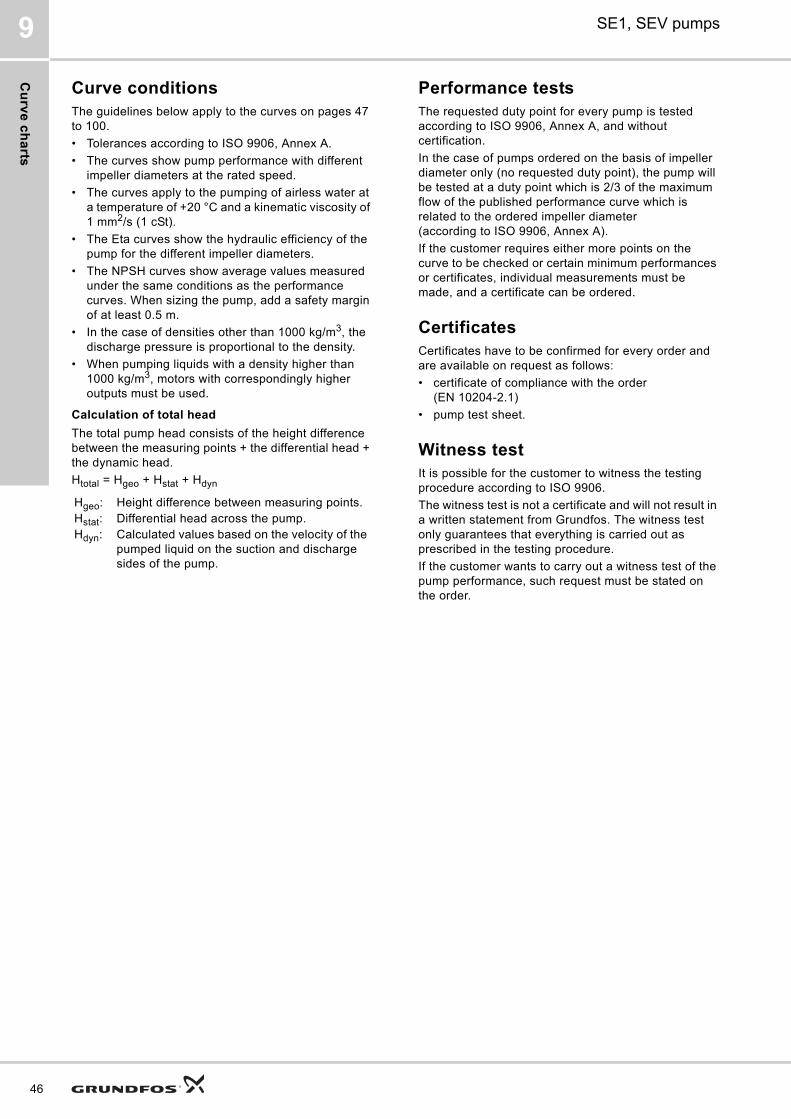
Cu
rve
ch
arts
46
SE1, SEV pumps9
Curve conditionsThe guidelines below apply to the curves on pages 47 to 100.
• Tolerances according to ISO 9906, Annex A.
• The curves show pump performance with different impeller diameters at the rated speed.
• The curves apply to the pumping of airless water at a temperature of +20 °C and a kinematic viscosity of 1 mm2/s (1 cSt).
• The Eta curves show the hydraulic efficiency of the pump for the different impeller diameters.
• The NPSH curves show average values measured under the same conditions as the performance curves. When sizing the pump, add a safety margin of at least 0.5 m.
• In the case of densities other than 1000 kg/m3, the discharge pressure is proportional to the density.
• When pumping liquids with a density higher than 1000 kg/m3, motors with correspondingly higher outputs must be used.
Calculation of total head
The total pump head consists of the height difference between the measuring points + the differential head + the dynamic head.
Htotal = Hgeo + Hstat + Hdyn
Performance testsThe requested duty point for every pump is tested according to ISO 9906, Annex A, and without certification.
In the case of pumps ordered on the basis of impeller diameter only (no requested duty point), the pump will be tested at a duty point which is 2/3 of the maximum flow of the published performance curve which is related to the ordered impeller diameter (according to ISO 9906, Annex A).
If the customer requires either more points on the curve to be checked or certain minimum performances or certificates, individual measurements must be made, and a certificate can be ordered.
CertificatesCertificates have to be confirmed for every order and are available on request as follows:
• certificate of compliance with the order (EN 10204-2.1)
• pump test sheet.
Witness testIt is possible for the customer to witness the testing procedure according to ISO 9906.
The witness test is not a certificate and will not result in a written statement from Grundfos. The witness test only guarantees that everything is carried out as prescribed in the testing procedure.
If the customer wants to carry out a witness test of the pump performance, such request must be stated on the order.
Hgeo: Height difference between measuring points.Hstat: Differential head across the pump.Hdyn: Calculated values based on the velocity of the
pumped liquid on the suction and discharge sides of the pump.
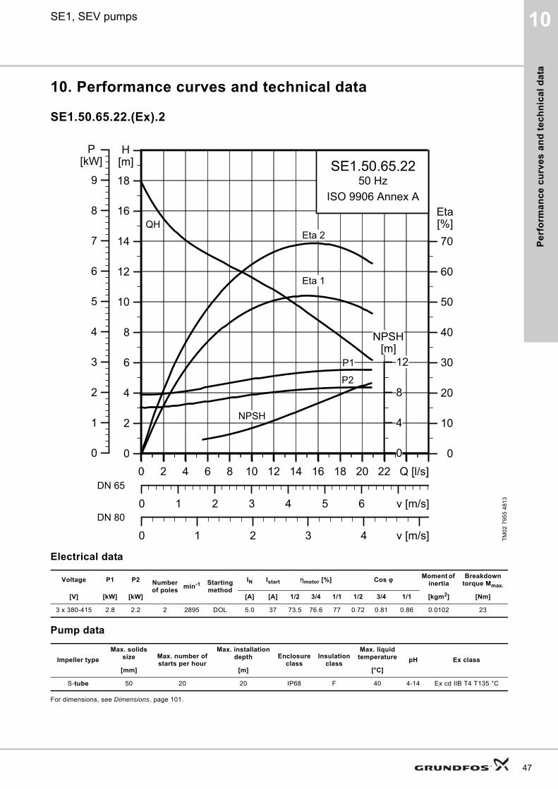
Pe
rfo
rma
nc
e c
urv
es
an
d t
ec
hn
ica
l d
ata
10SE1, SEV pumps
10. Performance curves and technical data
SE1.50.65.22.(Ex).2
Electrical data
Pump data
For dimensions, see Dimensions, page 101.
TM
02
79
55
48
13
Voltage P1 P2 Number of poles
min-1 Starting method
IN Istart ηmotor [%] Cos φ Moment of inertia
Breakdown torque Mmax.
[V] [kW] [kW] [A] [A] 1/2 3/4 1/1 1/2 3/4 1/1 [kgm2] [Nm]
3 x 380-415 2.8 2.2 2 2895 DOL 5.0 37 73.5 76.6 77 0.72 0.81 0.86 0.0102 23
Impeller type
Max. solids size Max. number of
starts per hour
Max. installation depth Enclosure
classInsulation
class
Max. liquid temperature pH Ex class
[mm] [m] [°C]
S-tube 50 20 20 IP68 F 40 4-14 Ex cd IIB T4 T135 °C
0 2 4 6 8 10 12 14 16 18 20 22 Q [l/s]0
2
4
6
8
10
12
14
16
18
[m]H
0 1 2 3 4 5 6 v [m/s]
0
10
20
30
40
50
60
70[%]Eta
0 1 2 3 4 v [m/s]
SE1.50.65.2250 Hz
ISO 9906 Annex A
Eta 1
Eta 2QH
P2
P1
NPSH
0 2 4 6 8 10 12 14 16 18 20 22 Q [l/s]0
1
2
3
4
5
6
7
8
9
[kW]P
0
4
8
12[m]
NPSH
DN 65
DN 80
47
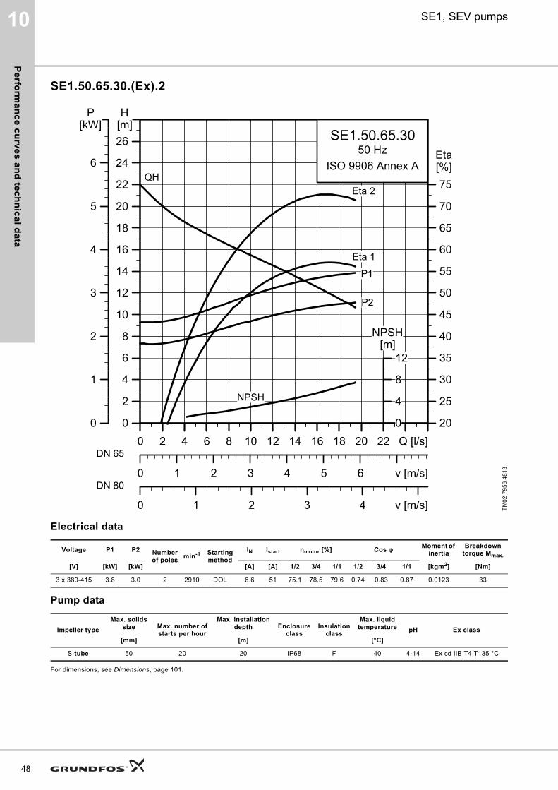
Pe
rform
an
ce
cu
rve
s a
nd
tec
hn
ica
l da
ta
48
10 SE1, SEV pumps
SE1.50.65.30.(Ex).2
Electrical data
Pump data
For dimensions, see Dimensions, page 101.
TM
02
79
56
48
13
Voltage P1 P2 Number of poles
min-1 Starting method
IN Istart ηmotor [%] Cos φ Moment of inertia
Breakdown torque Mmax.
[V] [kW] [kW] [A] [A] 1/2 3/4 1/1 1/2 3/4 1/1 [kgm2] [Nm]
3 x 380-415 3.8 3.0 2 2910 DOL 6.6 51 75.1 78.5 79.6 0.74 0.83 0.87 0.0123 33
Impeller type
Max. solids size Max. number of
starts per hour
Max. installation depth Enclosure
classInsulation
class
Max. liquid temperature pH Ex class
[mm] [m] [°C]
S-tube 50 20 20 IP68 F 40 4-14 Ex cd IIB T4 T135 °C
0 2 4 6 8 10 12 14 16 18 20 22 Q [l/s]0
2
4
6
8
10
12
14
16
18
20
22
24
26[m]H
0 1 2 3 4 5 6 v [m/s]
20
25
30
35
40
45
50
55
60
65
70
75[%]Eta
0 1 2 3 4 v [m/s]
SE1.50.65.3050 Hz
ISO 9906 Annex AQH
Eta 1
Eta 2
P2
P1
NPSH
0 2 4 6 8 10 12 14 16 18 20 22 Q [l/s]0
1
2
3
4
5
6
[kW]P
0
4
8
12[m]
NPSH
DN 65
DN 80
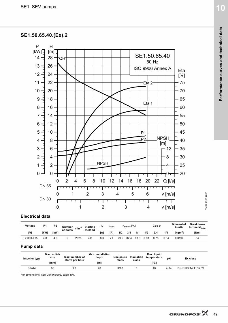
Pe
rfo
rma
nc
e c
urv
es
an
d t
ec
hn
ica
l d
ata
10SE1, SEV pumps
SE1.50.65.40.(Ex).2
Electrical data
Pump data
For dimensions, see Dimensions, page 101.
TM
02
79
58
48
13
Voltage P1 P2 Number of poles
min-1 Starting method
IN Istart ηmotor [%] Cos φ Moment of inertia
Breakdown torque Mmax.
[V] [kW] [kW] [A] [A] 1/2 3/4 1/1 1/2 3/4 1/1 [kgm2] [Nm]
3 x 380-415 4.8 4.0 2 2925 Y/D 8.6 71 79.2 82.4 83.3 0.68 0.78 0.84 0.0194 54
Impeller type
Max. solids size Max. number of
starts per hour
Max. installation depth Enclosure
classInsulation
class
Max. liquid temperature pH Ex class
[mm] [m] [°C]
S-tube 50 20 20 IP68 F 40 4-14 Ex cd IIB T4 T135 °C
0 2 4 6 8 10 12 14 16 18 20 22 Q [l/s]0
2
4
6
8
10
12
14
16
18
20
22
24
26
28[m]H
0 1 2 3 4 5 6 v [m/s]
20
25
30
35
40
45
50
55
60
65
70
75[%]Eta
0 1 2 3 4 v [m/s]
SE1.50.65.4050 Hz
ISO 9906 Annex A
QH
Eta 1
Eta 2
P2P1
NPSH
0 2 4 6 8 10 12 14 16 18 20 22 Q [l/s]0
1
2
3
4
5
6
7
8
9
10
11
12
13
14[kW]
P
0
4
8
12[m]
NPSH
DN 65
DN 80
49
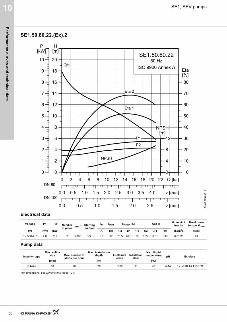
Pe
rform
an
ce
cu
rve
s a
nd
tec
hn
ica
l da
ta
50
10 SE1, SEV pumps
SE1.50.80.22.(Ex).2
Electrical data
Pump data
For dimensions, see Dimensions, page 101.
TM
02
79
54
48
13
Voltage P1 P2 Number of poles
min-1 Starting method
IN Istart ηmotor [%] Cos φ Moment of inertia
Breakdown torque Mmax.
[V] [kW] [kW] [A] [A] 1/2 3/4 1/1 1/2 3/4 1/1 [kgm2] [Nm]
3 x 380-415 2.8 2.2 2 2895 DOL 5.0 37 73.5 76.6 77 0.72 0.81 0.86 0.0102 23
Impeller type
Max. solids size Max. number of
starts per hour
Max. installation depth Enclosure
classInsulation
class
Max. liquid temperature pH Ex class
[mm] [m] [°C]
S-tube 50 20 20 IP68 F 40 4-14 Ex cd IIB T4 T135 °C
0 2 4 6 8 10 12 14 16 18 20 22 Q [l/s]0
2
4
6
8
10
12
14
16
18
20
[m]H
0.0 0.5 1.0 1.5 2.0 2.5 3.0 3.5 4.0 v [m/s]
0
10
20
30
40
50
60
70
80[%]Eta
0.0 0.5 1.0 1.5 2.0 2.5 v [m/s]
SE1.50.80.2250 Hz
ISO 9906 Annex AQH
Eta 1
Eta 2
P2
P1
NPSH
0 4 8 12 16 20 Q [l/s]0
1
2
3
4
5
6
7
8
9
10
[kW]P
0
4
8
12[m]
NPSH
DN 80
DN 100
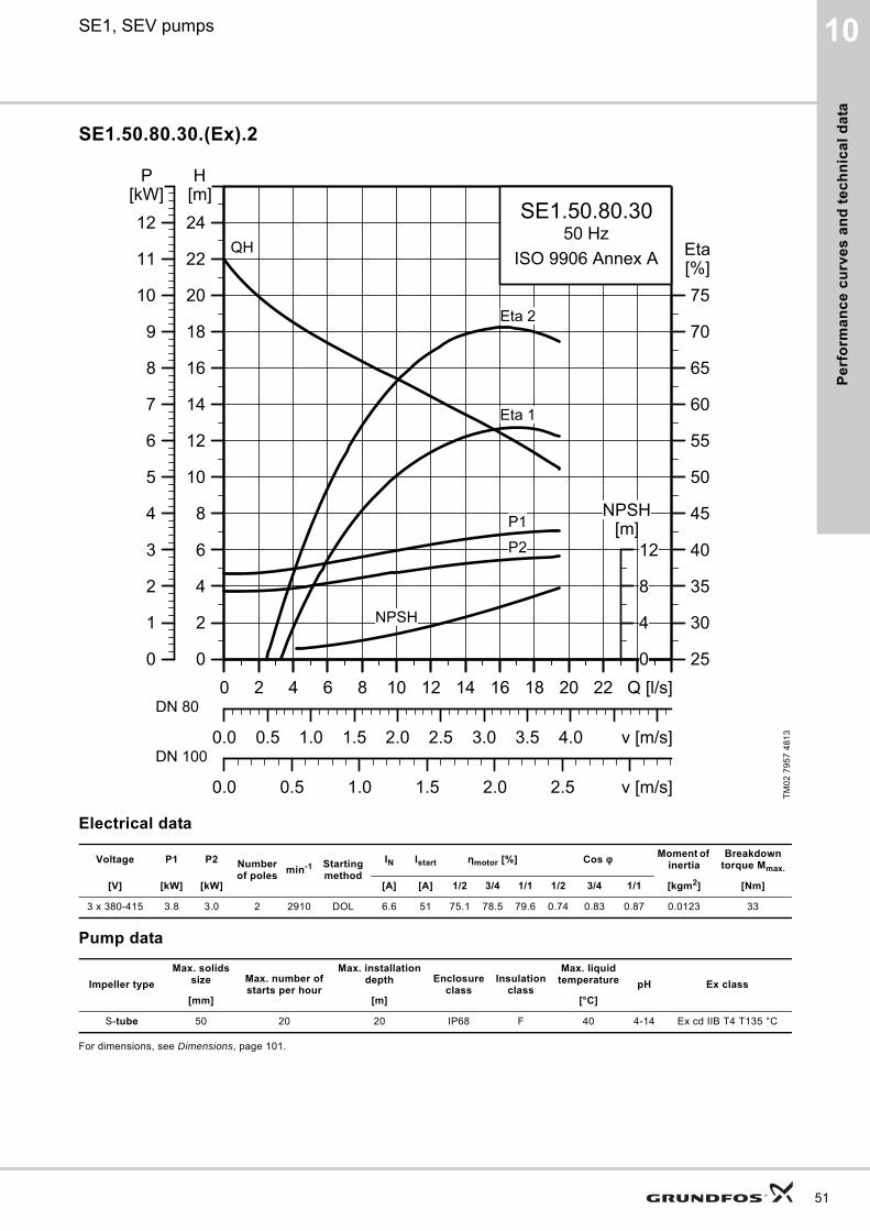
Pe
rfo
rma
nc
e c
urv
es
an
d t
ec
hn
ica
l d
ata
10SE1, SEV pumps
SE1.50.80.30.(Ex).2
Electrical data
Pump data
For dimensions, see Dimensions, page 101.
TM
02
79
57
48
13
Voltage P1 P2 Number of poles
min-1 Starting method
IN Istart ηmotor [%] Cos φ Moment of inertia
Breakdown torque Mmax.
[V] [kW] [kW] [A] [A] 1/2 3/4 1/1 1/2 3/4 1/1 [kgm2] [Nm]
3 x 380-415 3.8 3.0 2 2910 DOL 6.6 51 75.1 78.5 79.6 0.74 0.83 0.87 0.0123 33
Impeller type
Max. solids size Max. number of
starts per hour
Max. installation depth Enclosure
classInsulation
class
Max. liquid temperature pH Ex class
[mm] [m] [°C]
S-tube 50 20 20 IP68 F 40 4-14 Ex cd IIB T4 T135 °C
0 2 4 6 8 10 12 14 16 18 20 22 Q [l/s]0
2
4
6
8
10
12
14
16
18
20
22
24[m]H
0.0 0.5 1.0 1.5 2.0 2.5 3.0 3.5 4.0 v [m/s]
25
30
35
40
45
50
55
60
65
70
75[%]Eta
0.0 0.5 1.0 1.5 2.0 2.5 v [m/s]
SE1.50.80.3050 Hz
ISO 9906 Annex AQH
Eta 1
Eta 2
P2
P1
NPSH
0 2 4 6 8 10 12 14 16 18 20 22 Q [l/s]0
1
2
3
4
5
6
7
8
9
10
11
12[kW]
P
0
4
8
12[m]
NPSH
DN 80
DN 100
51
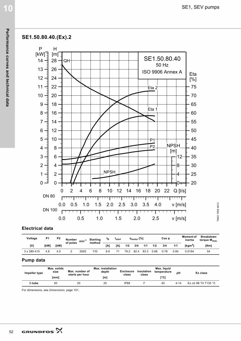
Pe
rform
an
ce
cu
rve
s a
nd
tec
hn
ica
l da
ta
52
10 SE1, SEV pumps
SE1.50.80.40.(Ex).2
Electrical data
Pump data
For dimensions, see Dimensions, page 101.
TM
02
79
59
48
13
Voltage P1 P2 Number of poles
min-1 Starting method
IN Istart ηmotor [%] Cos φ Moment of inertia
Breakdown torque Mmax.
[V] [kW] [kW] [A] [A] 1/2 3/4 1/1 1/2 3/4 1/1 [kgm2] [Nm]
3 x 380-415 4.8 4.0 2 2925 Y/D 8.6 71 79.2 82.4 83.3 0.68 0.78 0.84 0.0194 54
Impeller type
Max. solids size Max. number of
starts per hour
Max. installation depth Enclosure
classInsulation
class
Max. liquid temperature pH Ex class
[mm] [m] [°C]
S-tube 50 20 20 IP68 F 40 4-14 Ex cd IIB T4 T135 °C
0 2 4 6 8 10 12 14 16 18 20 22 Q [l/s]0
2
4
6
8
10
12
14
16
18
20
22
24
26
28[m]H
0.0 0.5 1.0 1.5 2.0 2.5 3.0 3.5 4.0 v [m/s]
20
25
30
35
40
45
50
55
60
65
70
75[%]Eta
0.0 0.5 1.0 1.5 2.0 2.5 v [m/s]
SE1.50.80.4050 Hz
ISO 9906 Annex A
QH
Eta 1
Eta 2
P2P1
NPSH
0 2 4 6 8 10 12 14 16 18 20 22 Q [l/s]0
1
2
3
4
5
6
7
8
9
10
11
12
13
14[kW]
P
0
4
8
12[m]
NPSH
DN 80
DN 100
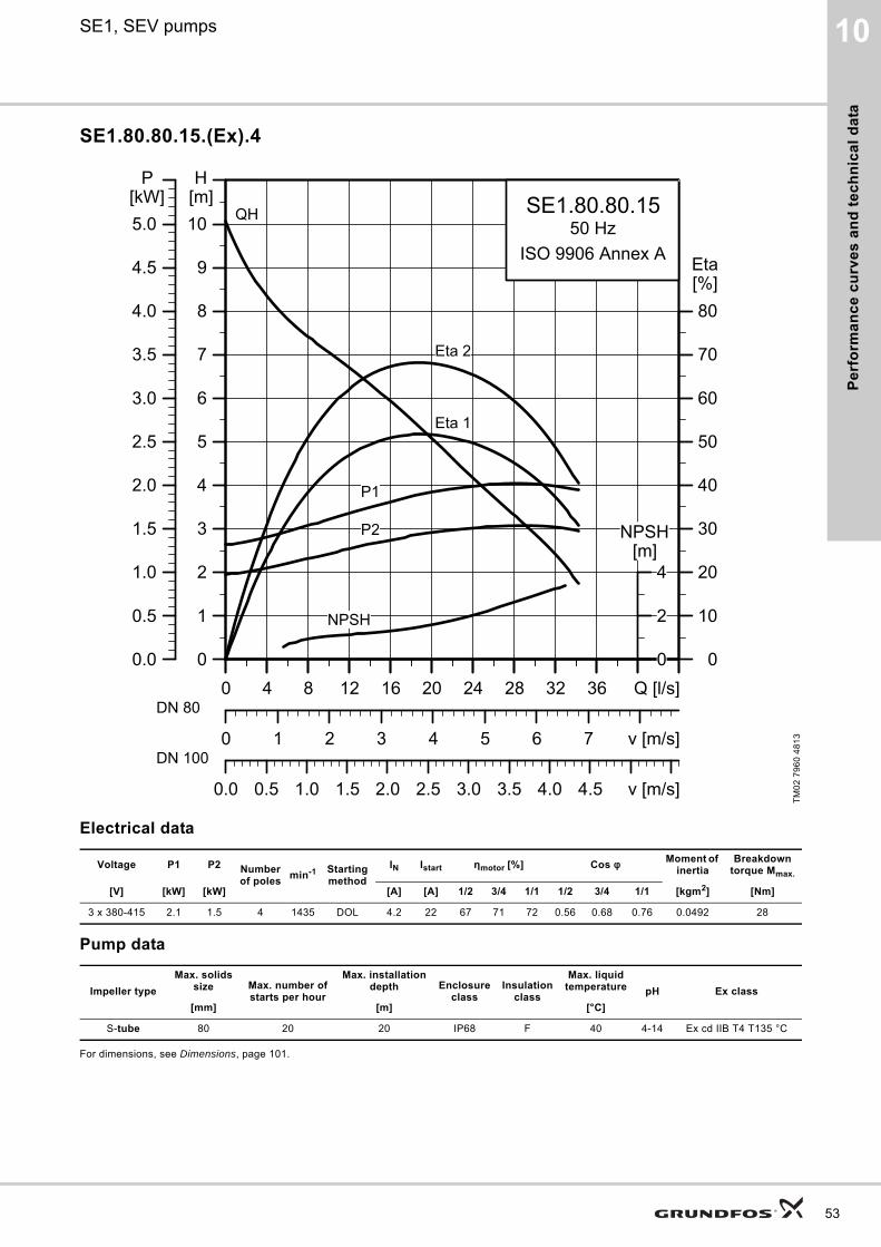
Pe
rfo
rma
nc
e c
urv
es
an
d t
ec
hn
ica
l d
ata
10SE1, SEV pumps
SE1.80.80.15.(Ex).4
Electrical data
Pump data
For dimensions, see Dimensions, page 101.
TM
02
79
60
48
13
Voltage P1 P2 Number of poles
min-1 Starting method
IN Istart ηmotor [%] Cos φ Moment of inertia
Breakdown torque Mmax.
[V] [kW] [kW] [A] [A] 1/2 3/4 1/1 1/2 3/4 1/1 [kgm2] [Nm]
3 x 380-415 2.1 1.5 4 1435 DOL 4.2 22 67 71 72 0.56 0.68 0.76 0.0492 28
Impeller type
Max. solids size Max. number of
starts per hour
Max. installation depth Enclosure
classInsulation
class
Max. liquid temperature pH Ex class
[mm] [m] [°C]
S-tube 80 20 20 IP68 F 40 4-14 Ex cd IIB T4 T135 °C
0 4 8 12 16 20 24 28 32 36 Q [l/s]0
1
2
3
4
5
6
7
8
9
10[m]H
0 1 2 3 4 5 6 7 v [m/s]
0
10
20
30
40
50
60
70
80[%]Eta
0.0 0.5 1.0 1.5 2.0 2.5 3.0 3.5 4.0 4.5 v [m/s]
SE1.80.80.1550 Hz
ISO 9906 Annex A
Eta 2
Eta 1
QH
P2
P1
NPSH
0 4 8 12 16 20 24 28 32 36 Q [l/s]0.0
0.5
1.0
1.5
2.0
2.5
3.0
3.5
4.0
4.5
5.0[kW]
P
0
2
4[m]
NPSH
DN 80
DN 100
53
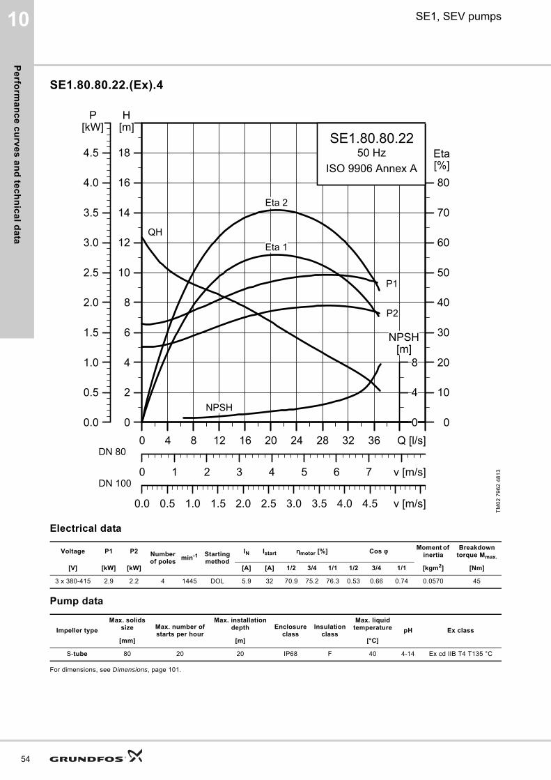
Pe
rform
an
ce
cu
rve
s a
nd
tec
hn
ica
l da
ta
54
10 SE1, SEV pumps
SE1.80.80.22.(Ex).4
Electrical data
Pump data
For dimensions, see Dimensions, page 101.
TM
02
79
62
48
13
Voltage P1 P2 Number of poles
min-1 Starting method
IN Istart ηmotor [%] Cos φ Moment of inertia
Breakdown torque Mmax.
[V] [kW] [kW] [A] [A] 1/2 3/4 1/1 1/2 3/4 1/1 [kgm2] [Nm]
3 x 380-415 2.9 2.2 4 1445 DOL 5.9 32 70.9 75.2 76.3 0.53 0.66 0.74 0.0570 45
Impeller type
Max. solids size Max. number of
starts per hour
Max. installation depth Enclosure
classInsulation
class
Max. liquid temperature pH Ex class
[mm] [m] [°C]
S-tube 80 20 20 IP68 F 40 4-14 Ex cd IIB T4 T135 °C
0 4 8 12 16 20 24 28 32 36 Q [l/s]0
2
4
6
8
10
12
14
16
18
[m]H
0 1 2 3 4 5 6 7 v [m/s]
0
10
20
30
40
50
60
70
80[%]Eta
0.0 0.5 1.0 1.5 2.0 2.5 3.0 3.5 4.0 4.5 v [m/s]
SE1.80.80.2250 Hz
ISO 9906 Annex A
Eta 2
Eta 1QH
P2
P1
NPSH
0 4 8 12 16 20 24 28 32 36 Q [l/s]0.0
0.5
1.0
1.5
2.0
2.5
3.0
3.5
4.0
4.5
[kW]P
0
4
8[m]
NPSH
DN 80
DN 100
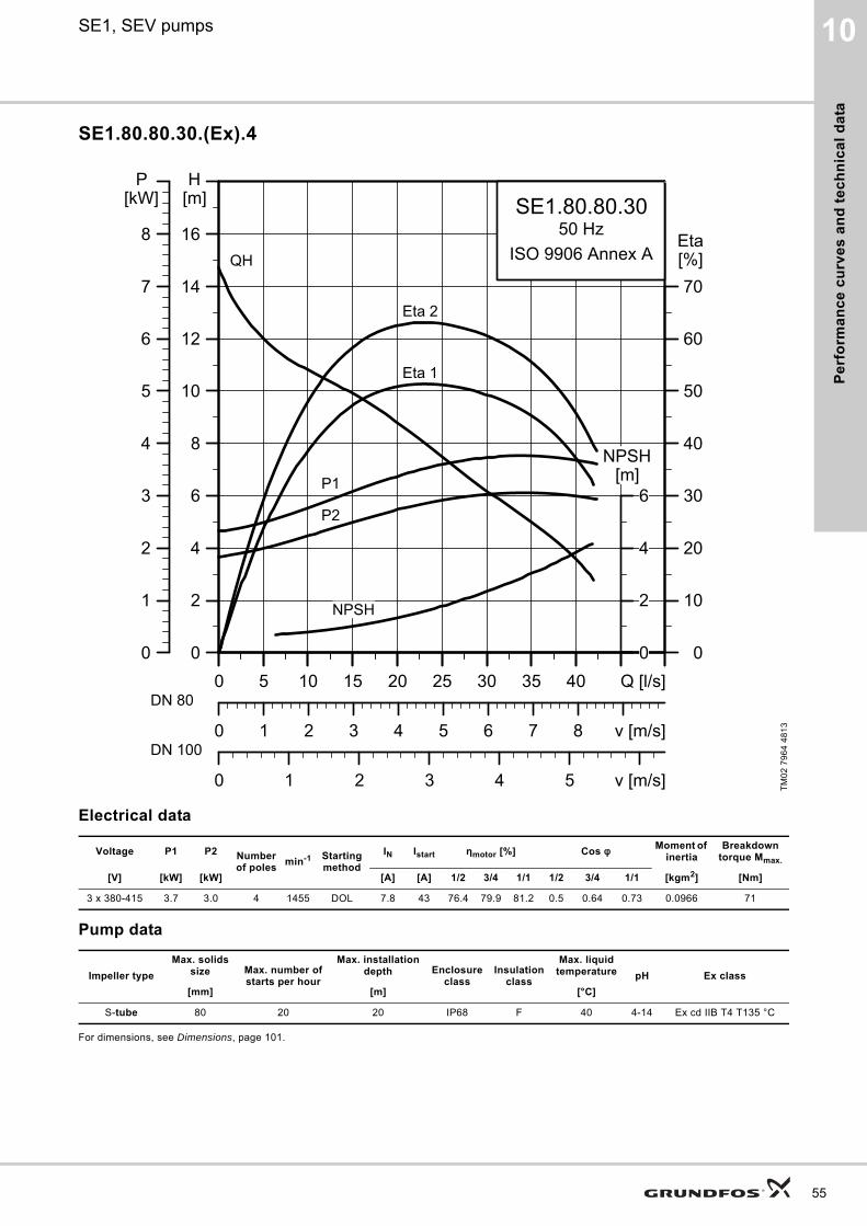
Pe
rfo
rma
nc
e c
urv
es
an
d t
ec
hn
ica
l d
ata
10SE1, SEV pumps
SE1.80.80.30.(Ex).4
Electrical data
Pump data
For dimensions, see Dimensions, page 101.
TM
02
79
64
48
13
Voltage P1 P2 Number of poles
min-1 Starting method
IN Istart ηmotor [%] Cos φ Moment of inertia
Breakdown torque Mmax.
[V] [kW] [kW] [A] [A] 1/2 3/4 1/1 1/2 3/4 1/1 [kgm2] [Nm]
3 x 380-415 3.7 3.0 4 1455 DOL 7.8 43 76.4 79.9 81.2 0.5 0.64 0.73 0.0966 71
Impeller type
Max. solids size Max. number of
starts per hour
Max. installation depth Enclosure
classInsulation
class
Max. liquid temperature pH Ex class
[mm] [m] [°C]
S-tube 80 20 20 IP68 F 40 4-14 Ex cd IIB T4 T135 °C
0 5 10 15 20 25 30 35 40 Q [l/s]0
2
4
6
8
10
12
14
16
[m]H
0 1 2 3 4 5 6 7 8 v [m/s]
0
10
20
30
40
50
60
70[%]Eta
0 1 2 3 4 5 v [m/s]
SE1.80.80.3050 Hz
ISO 9906 Annex AQH
Eta 1
Eta 2
P2
P1
NPSH
0 5 10 15 20 25 30 35 40 Q [l/s]0
1
2
3
4
5
6
7
8
[kW]P
0
2
4
6[m]
NPSH
DN 80
DN 100
55

Pe
rform
an
ce
cu
rve
s a
nd
tec
hn
ica
l da
ta
56
10 SE1, SEV pumps
SE1.80.80.40.(Ex).4
Electrical data
Pump data
For dimensions, see Dimensions, page 101.
TM
02
79
66
48
13
Voltage P1 P2 Number of poles
min-1 Starting method
IN Istart ηmotor [%] Cos φ Moment of inertia
Breakdown torque Mmax.
[V] [kW] [kW] [A] [A] 1/2 3/4 1/1 1/2 3/4 1/1 [kgm2] [Nm]
3 x 380-415 4.9 4.0 4 1460 Y/D 10 67 78.2 81.7 82.2 0.52 0.65 0.73 0.1141 100
Impeller type
Max. solids size Max. number of
starts per hour
Max. installation depth Enclosure
classInsulation
class
Max. liquid temperature pH Ex class
[mm] [m] [°C]
S-tube 80 20 20 IP68 F 40 4-14 Ex cd IIB T4 T135 °C
0 5 10 15 20 25 30 35 40 45 50 Q [l/s]0
2
4
6
8
10
12
14
16
18
[m]H
0 1 2 3 4 5 6 7 8 9 10 v [m/s]
0
10
20
30
40
50
60
70[%]Eta
0 1 2 3 4 5 6 v [m/s]
SE1.80.80.4050 Hz
ISO 9906 Annex A
QH
Eta 1
Eta 2
P2
P1
NPSH
0 5 10 15 20 25 30 35 40 45 50 Q [l/s]0
1
2
3
4
5
6
7
8
9
[kW]P
0
4
8[m]
NPSH
DN 80
DN 100
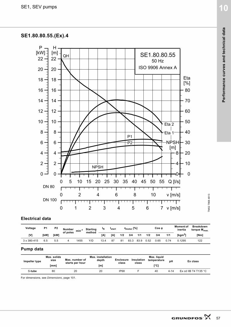
Pe
rfo
rma
nc
e c
urv
es
an
d t
ec
hn
ica
l d
ata
10SE1, SEV pumps
SE1.80.80.55.(Ex).4
Electrical data
Pump data
For dimensions, see Dimensions, page 101.
TM
02
79
68
48
13
Voltage P1 P2 Number of poles
min-1 Starting method
IN Istart ηmotor [%] Cos φ Moment of inertia
Breakdown torque Mmax.
[V] [kW] [kW] [A] [A] 1/2 3/4 1/1 1/2 3/4 1/1 [kgm2] [Nm]
3 x 380-415 6.5 5.5 4 1455 Y/D 13.4 87 81 83.3 83.9 0.52 0.65 0.74 0.1295 122
Impeller type
Max. solids size Max. number of
starts per hour
Max. installation depth Enclosure
classInsulation
class
Max. liquid temperature pH Ex class
[mm] [m] [°C]
S-tube 80 20 20 IP68 F 40 4-14 Ex cd IIB T4 T135 °C
0 5 10 15 20 25 30 35 40 45 50 55 Q [l/s]0
2
4
6
8
10
12
14
16
18
20
22[m]H
0 2 4 6 8 10 v [m/s]
0
10
20
30
40
50
60
70
80[%]Eta
0 1 2 3 4 5 6 7 v [m/s]
SE1.80.80.5550 Hz
ISO 9906 Annex A
QH
Eta 1
Eta 2
P2P1
NPSH
0 5 10 15 20 25 30 35 40 45 50 55 Q [l/s]0
2
4
6
8
10
12
14
16
18
20
22[kW]
P
0
4
8[m]
NPSH
DN 80
DN 100
57

Pe
rform
an
ce
cu
rve
s a
nd
tec
hn
ica
l da
ta
58
10 SE1, SEV pumps
SE1.80.80.75.(Ex).4
Electrical data
Pump data
For dimensions, see Dimensions, page 101.
TM
02
79
70
48
13
Voltage P1 P2 Number of poles
min-1 Starting method
IN Istart ηmotor [%] Cos φ Moment of inertia
Breakdown torque Mmax.
[V] [kW] [kW] [A] [A] 1/2 3/4 1/1 1/2 3/4 1/1 [kgm2] [Nm]
3 x 380-415 9.0 7.5 4 1455 Y/D 17.3 107 81.3 83.5 83.4 0.61 0.72 0.79 0.1618 141
Impeller type
Max. solids size Max. number of
starts per hour
Max. installation depth Enclosure
classInsulation
class
Max. liquid temperature pH Ex class
[mm] [m] [°C]
S-tube 80 20 20 IP68 F 40 4-14 Ex cd IIB T4 T135 °C
0 5 10 15 20 25 30 35 40 45 50 55 60 Q [l/s]0
2
4
6
8
10
12
14
16
18
20
22
24
26[m]H
0 2 4 6 8 10 12v [m/s]
0
10
20
30
40
50
60
70
80[%]Eta
0 1 2 3 4 5 6 7 v [m/s]
SE1.80.80.7550 Hz
ISO 9906 Annex A
QH
Eta 1
Eta 2
P2
P1
NPSH
0 5 10 15 20 25 30 35 40 45 50 55 60 Q [l/s]0
2
4
6
8
10
12
14
16
18
20
22
24
26[kW]
P
0
5
10
15[m]
NPSH
DN 80
DN 100
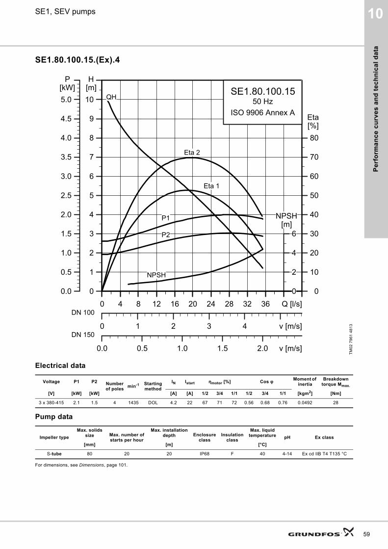
Pe
rfo
rma
nc
e c
urv
es
an
d t
ec
hn
ica
l d
ata
10SE1, SEV pumps
SE1.80.100.15.(Ex).4
Electrical data
Pump data
For dimensions, see Dimensions, page 101.
TM
02
79
61
48
13
Voltage P1 P2 Number of poles
min-1 Starting method
IN Istart ηmotor [%] Cos φ Moment of inertia
Breakdown torque Mmax.
[V] [kW] [kW] [A] [A] 1/2 3/4 1/1 1/2 3/4 1/1 [kgm2] [Nm]
3 x 380-415 2.1 1.5 4 1435 DOL 4.2 22 67 71 72 0.56 0.68 0.76 0.0492 28
Impeller type
Max. solids size Max. number of
starts per hour
Max. installation depth Enclosure
classInsulation
class
Max. liquid temperature pH Ex class
[mm] [m] [°C]
S-tube 80 20 20 IP68 F 40 4-14 Ex cd IIB T4 T135 °C
0 4 8 12 16 20 24 28 32 36 Q [l/s]0
1
2
3
4
5
6
7
8
9
10[m]H
0 1 2 3 4 v [m/s]
0
10
20
30
40
50
60
70
80[%]Eta
0.0 0.5 1.0 1.5 2.0 v [m/s]
SE1.80.100.1550 Hz
ISO 9906 Annex A
QH
Eta 1
Eta 2
P2
P1
NPSH
0 4 8 12 16 20 24 28 32 36 Q [l/s]0.0
0.5
1.0
1.5
2.0
2.5
3.0
3.5
4.0
4.5
5.0[kW]
P
0
2
4
6[m]
NPSH
DN 100
DN 150
59
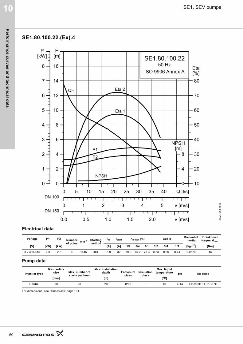
Pe
rform
an
ce
cu
rve
s a
nd
tec
hn
ica
l da
ta
60
10 SE1, SEV pumps
SE1.80.100.22.(Ex).4
Electrical data
Pump data
For dimensions, see Dimensions, page 101.
TM
02
79
63
48
13
Voltage P1 P2 Number of poles
min-1 Starting method
IN Istart ηmotor [%] Cos φ Moment of inertia
Breakdown torque Mmax.
[V] [kW] [kW] [A] [A] 1/2 3/4 1/1 1/2 3/4 1/1 [kgm2] [Nm]
3 x 380-415 2.9 2.2 4 1445 DOL 5.9 32 70.9 75.2 76.3 0.53 0.66 0.74 0.0570 45
Impeller type
Max. solids size Max. number of
starts per hour
Max. installation depth Enclosure
classInsulation
class
Max. liquid temperature pH Ex class
[mm] [m] [°C]
S-tube 80 20 20 IP68 F 40 4-14 Ex cd IIB T4 T135 °C
0 5 10 15 20 25 30 35 40 Q [l/s]0
2
4
6
8
10
12
14
16
[m]H
0 1 2 3 4 5 v [m/s]
10
20
30
40
50
60
70
80[%]Eta
0.0 0.5 1.0 1.5 2.0 v [m/s]
SE1.80.100.2250 Hz
ISO 9906 Annex A
QH
Eta 1
Eta 2
P2
P1
NPSH
0 5 10 15 20 25 30 35 40 Q [l/s]0
1
2
3
4
5
6
7
8
[kW]P
0
4
8[m]
NPSH
DN 100
DN 150
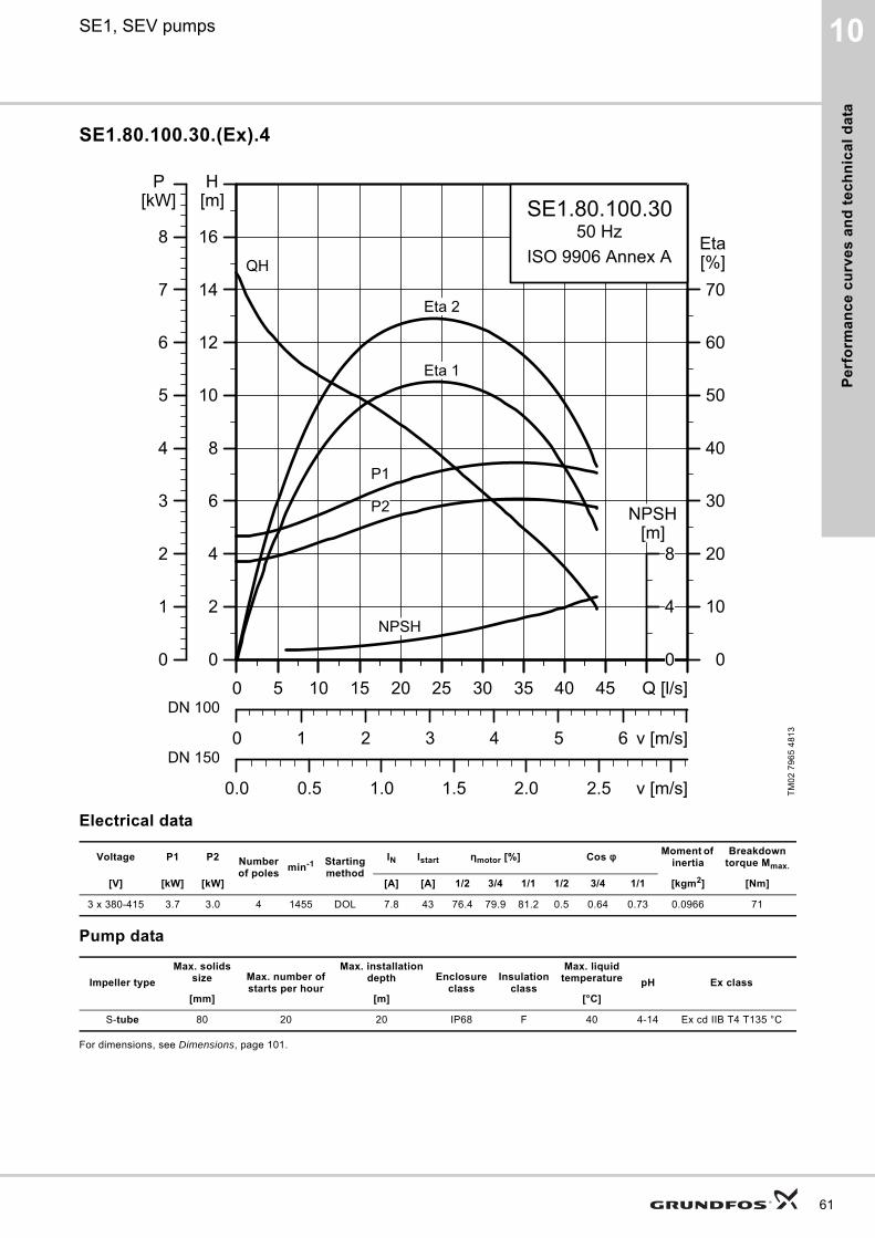
Pe
rfo
rma
nc
e c
urv
es
an
d t
ec
hn
ica
l d
ata
10SE1, SEV pumps
SE1.80.100.30.(Ex).4
Electrical data
Pump data
For dimensions, see Dimensions, page 101.
TM
02
79
65
48
13
Voltage P1 P2 Number of poles
min-1 Starting method
IN Istart ηmotor [%] Cos φ Moment of inertia
Breakdown torque Mmax.
[V] [kW] [kW] [A] [A] 1/2 3/4 1/1 1/2 3/4 1/1 [kgm2] [Nm]
3 x 380-415 3.7 3.0 4 1455 DOL 7.8 43 76.4 79.9 81.2 0.5 0.64 0.73 0.0966 71
Impeller type
Max. solids size Max. number of
starts per hour
Max. installation depth Enclosure
classInsulation
class
Max. liquid temperature pH Ex class
[mm] [m] [°C]
S-tube 80 20 20 IP68 F 40 4-14 Ex cd IIB T4 T135 °C
0 5 10 15 20 25 30 35 40 45 Q [l/s]0
2
4
6
8
10
12
14
16
[m]H
0 1 2 3 4 5 6 v [m/s]
0
10
20
30
40
50
60
70[%]Eta
0.0 0.5 1.0 1.5 2.0 2.5 v [m/s]
SE1.80.100.3050 Hz
ISO 9906 Annex AQH
Eta 1
Eta 2
P2
P1
NPSH
0 5 10 15 20 25 30 35 40 45 Q [l/s]0
1
2
3
4
5
6
7
8
[kW]P
0
4
8[m]
NPSH
DN 100
DN 150
61
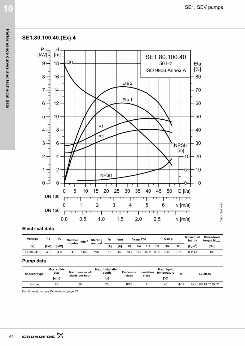
Pe
rform
an
ce
cu
rve
s a
nd
tec
hn
ica
l da
ta
62
10 SE1, SEV pumps
SE1.80.100.40.(Ex).4
Electrical data
Pump data
For dimensions, see Dimensions, page 101.
TM
02
79
67
48
13
Voltage P1 P2 Number of poles
min-1 Starting method
IN Istart ηmotor [%] Cos φ Moment of inertia
Breakdown torque Mmax.
[V] [kW] [kW] [A] [A] 1/2 3/4 1/1 1/2 3/4 1/1 [kgm2] [Nm]
3 x 380-415 4.9 4.0 4 1460 Y/D 10 67 78.2 81.7 82.2 0.52 0.65 0.73 0.1141 100
Impeller type
Max. solids size Max. number of
starts per hour
Max. installation depth Enclosure
classInsulation
class
Max. liquid temperature pH Ex class
[mm] [m] [°C]
S-tube 80 20 20 IP68 F 40 4-14 Ex cd IIB T4 T135 °C
0 5 10 15 20 25 30 35 40 45 50 Q [l/s]0
2
4
6
8
10
12
14
16
18
[m]H
0 1 2 3 4 5 6 v [m/s]
0
10
20
30
40
50
60
70
80[%]Eta
0.0 0.5 1.0 1.5 2.0 2.5 v [m/s]
SE1.80.100.4050 Hz
ISO 9906 Annex A
QH
Eta 1
Eta 2
P2
P1
NPSH
0 5 10 15 20 25 30 35 40 45 50 Q [l/s]0
1
2
3
4
5
6
7
8
9
[kW]P
0
5
10[m]
NPSH
DN 100
DN 150
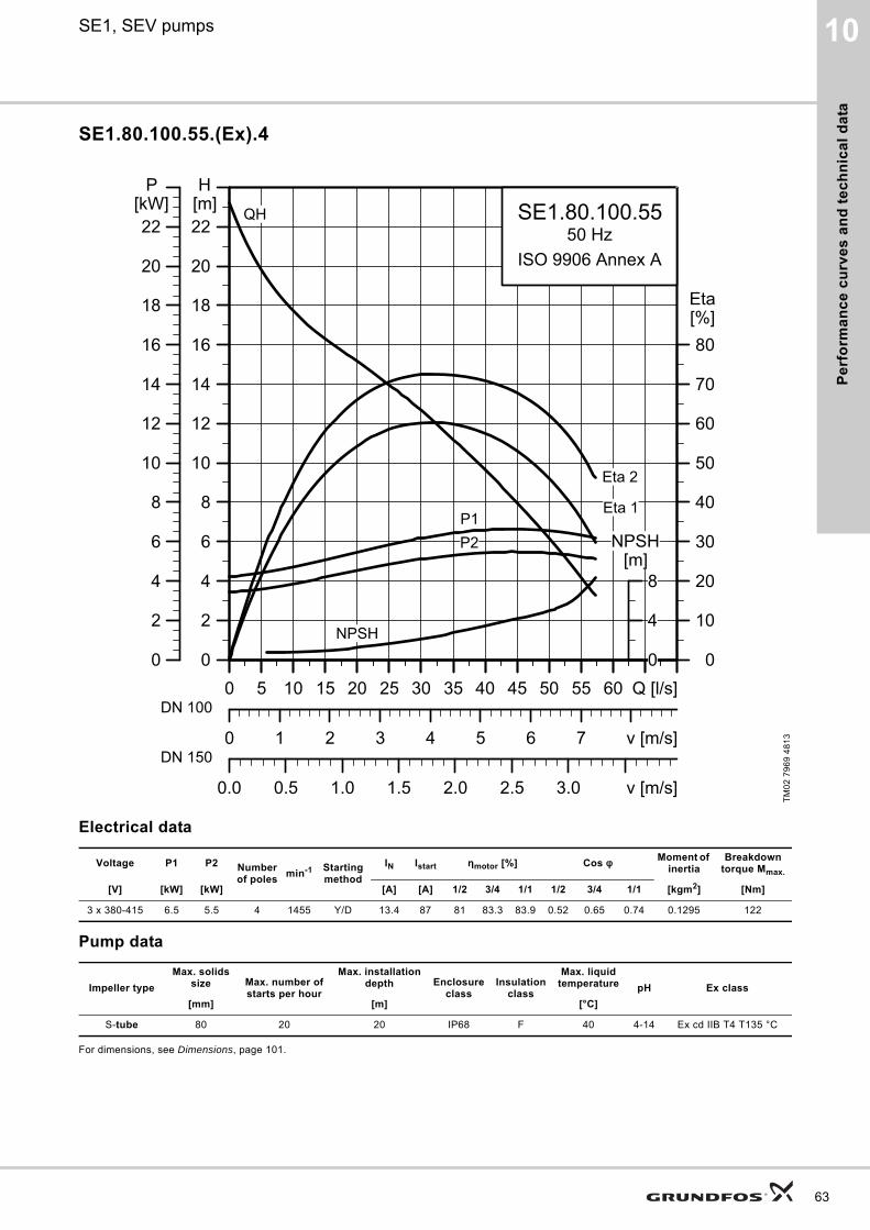
Pe
rfo
rma
nc
e c
urv
es
an
d t
ec
hn
ica
l d
ata
10SE1, SEV pumps
SE1.80.100.55.(Ex).4
Electrical data
Pump data
For dimensions, see Dimensions, page 101.
TM
02
79
69
48
13
Voltage P1 P2 Number of poles
min-1 Starting method
IN Istart ηmotor [%] Cos φ Moment of inertia
Breakdown torque Mmax.
[V] [kW] [kW] [A] [A] 1/2 3/4 1/1 1/2 3/4 1/1 [kgm2] [Nm]
3 x 380-415 6.5 5.5 4 1455 Y/D 13.4 87 81 83.3 83.9 0.52 0.65 0.74 0.1295 122
Impeller type
Max. solids size Max. number of
starts per hour
Max. installation depth Enclosure
classInsulation
class
Max. liquid temperature pH Ex class
[mm] [m] [°C]
S-tube 80 20 20 IP68 F 40 4-14 Ex cd IIB T4 T135 °C
0 5 10 15 20 25 30 35 40 45 50 55 60 Q [l/s]0
2
4
6
8
10
12
14
16
18
20
22[m]H
0 1 2 3 4 5 6 7 v [m/s]
0
10
20
30
40
50
60
70
80[%]Eta
0.0 0.5 1.0 1.5 2.0 2.5 3.0 v [m/s]
SE1.80.100.5550 Hz
ISO 9906 Annex A
QH
Eta 1
Eta 2
P2P1
NPSH
0 5 10 15 20 25 30 35 40 45 50 55 60 Q [l/s]0
2
4
6
8
10
12
14
16
18
20
22[kW]
P
0
4
8[m]
NPSH
DN 100
DN 150
63
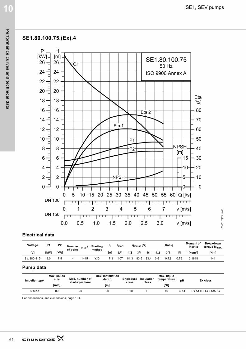
Pe
rform
an
ce
cu
rve
s a
nd
tec
hn
ica
l da
ta
64
10 SE1, SEV pumps
SE1.80.100.75.(Ex).4
Electrical data
Pump data
For dimensions, see Dimensions, page 101.
TM
02
79
71
48
13
Voltage P1 P2 Number of poles
min-1 Starting method
IN Istart ηmotor [%] Cos φ Moment of inertia
Breakdown torque Mmax.
[V] [kW] [kW] [A] [A] 1/2 3/4 1/1 1/2 3/4 1/1 [kgm2] [Nm]
3 x 380-415 9.0 7.5 4 1445 Y/D 17.3 107 81.3 83.5 83.4 0.61 0.72 0.79 0.1618 141
Impeller type
Max. solids size Max. number of
starts per hour
Max. installation depth Enclosure
classInsulation
class
Max. liquid temperature pH Ex class
[mm] [m] [°C]
S-tube 80 20 20 IP68 F 40 4-14 Ex cd IIB T4 T135 °C
0 5 10 15 20 25 30 35 40 45 50 55 60 Q [l/s]0
2
4
6
8
10
12
14
16
18
20
22
24
26[m]H
0 1 2 3 4 5 6 7 v [m/s]
0
10
20
30
40
50
60
70
80[%]Eta
0.0 0.5 1.0 1.5 2.0 2.5 3.0 v [m/s]
SE1.80.100.7550 Hz
ISO 9906 Annex A
QH
Eta 1
Eta 2
P2
P1
NPSH
0 5 10 15 20 25 30 35 40 45 50 55 60 Q [l/s]0
2
4
6
8
10
12
14
16
18
20
22
24
26[kW]
P
0
5
10
15[m]
NPSH
DN 100
DN 150
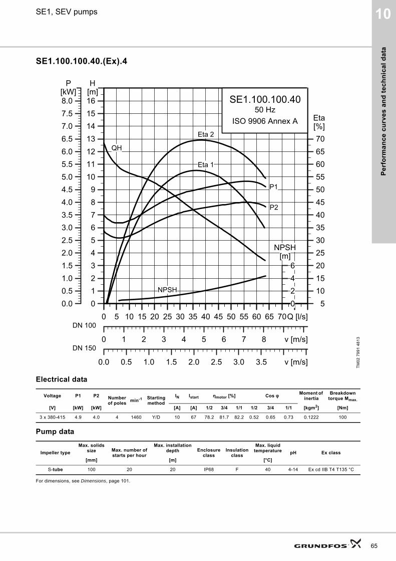
Pe
rfo
rma
nc
e c
urv
es
an
d t
ec
hn
ica
l d
ata
10SE1, SEV pumps
SE1.100.100.40.(Ex).4
Electrical data
Pump data
For dimensions, see Dimensions, page 101.
TM
02
79
91
48
13
Voltage P1 P2 Number of poles
min-1 Starting method
IN Istart ηmotor [%] Cos φ Moment of inertia
Breakdown torque Mmax.
[V] [kW] [kW] [A] [A] 1/2 3/4 1/1 1/2 3/4 1/1 [kgm2] [Nm]
3 x 380-415 4.9 4.0 4 1460 Y/D 10 67 78.2 81.7 82.2 0.52 0.65 0.73 0.1222 100
Impeller type
Max. solids size Max. number of
starts per hour
Max. installation depth Enclosure
classInsulation
class
Max. liquid temperature pH Ex class
[mm] [m] [°C]
S-tube 100 20 20 IP68 F 40 4-14 Ex cd IIB T4 T135 °C
0 5 10 15 20 25 30 35 40 45 50 55 60 65 70Q [l/s]0123456789
10111213141516[m]H
0 1 2 3 4 5 6 7 8 v [m/s]
510152025303540455055606570
[%]Eta
0.0 0.5 1.0 1.5 2.0 2.5 3.0 3.5 v [m/s]
SE1.100.100.4050 Hz
ISO 9906 Annex A
QH
Eta 1
Eta 2
P2
P1
NPSH
0 5 10 15 20 25 30 35 40 45 50 55 60 65 70Q [l/s]0.00.51.01.52.02.53.03.54.04.55.05.56.06.57.07.58.0[kW]
P
0246
[m]NPSH
DN 100
DN 150
65
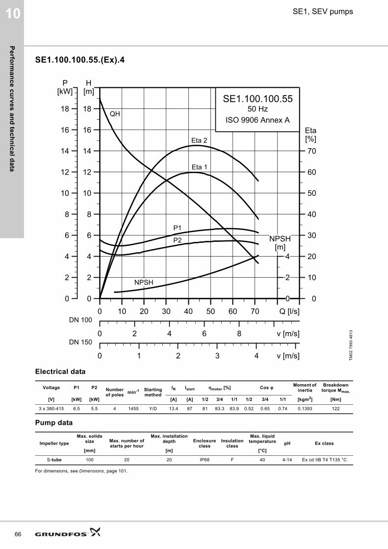
Pe
rform
an
ce
cu
rve
s a
nd
tec
hn
ica
l da
ta
66
10 SE1, SEV pumps
SE1.100.100.55.(Ex).4
Electrical data
Pump data
For dimensions, see Dimensions, page 101.
TM
02
79
93
48
13
Voltage P1 P2 Number of poles
min-1 Starting method
IN Istart ηmotor [%] Cos φ Moment of inertia
Breakdown torque Mmax.
[V] [kW] [kW] [A] [A] 1/2 3/4 1/1 1/2 3/4 1/1 [kgm2] [Nm]
3 x 380-415 6.5 5.5 4 1455 Y/D 13.4 87 81 83.3 83.9 0.52 0.65 0.74 0.1393 122
Impeller type
Max. solids size Max. number of
starts per hour
Max. installation depth Enclosure
classInsulation
class
Max. liquid temperature pH Ex class
[mm] [m] [°C]
S-tube 100 20 20 IP68 F 40 4-14 Ex cd IIB T4 T135 °C
0 10 20 30 40 50 60 70 Q [l/s]0
2
4
6
8
10
12
14
16
18
[m]H
0 2 4 6 8 v [m/s]
0
10
20
30
40
50
60
70[%]Eta
0 1 2 3 4 v [m/s]
SE1.100.100.5550 Hz
ISO 9906 Annex AQH
Eta 1
Eta 2
P2
P1
NPSH
0 10 20 30 40 50 60 70 Q [l/s]0
2
4
6
8
10
12
14
16
18
[kW]P
0
2
4[m]
NPSH
DN 100
DN 150
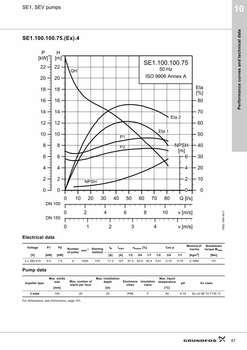
Pe
rfo
rma
nc
e c
urv
es
an
d t
ec
hn
ica
l d
ata
10SE1, SEV pumps
SE1.100.100.75.(Ex).4
Electrical data
Pump data
For dimensions, see Dimensions, page 101.
TM
02
79
95
48
13
Voltage P1 P2 Number of poles
min-1 Starting method
IN Istart ηmotor [%] Cos φ Moment of inertia
Breakdown torque Mmax.
[V] [kW] [kW] [A] [A] 1/2 3/4 1/1 1/2 3/4 1/1 [kgm2] [Nm]
3 x 380-415 9.0 7.5 4 1455 Y/D 17.3 107 81.3 83.5 83.4 0.61 0.72 0.79 0.1860 141
Impeller type
Max. solids size Max. number of
starts per hour
Max. installation depth Enclosure
classInsulation
class
Max. liquid temperature pH Ex class
[mm] [m] [°C]
S-tube 100 20 20 IP68 F 40 4-14 Ex cd IIB T4 T135 °C
0 10 20 30 40 50 60 70 80 Q [l/s]0
2
4
6
8
10
12
14
16
18
20
22
[m]H
0 2 4 6 8 10 v [m/s]
0
10
20
30
40
50
60
70
80[%]Eta
0 1 2 3 4 v [m/s]
SE1.100.100.7550 Hz
ISO 9906 Annex AQH
Eta 1
Eta 2
P2
P1
NPSH
0 10 20 30 40 50 60 70 80 Q [l/s]0
2
4
6
8
10
12
14
16
18
20
22
[kW]P
0
2
4
6[m]
NPSH
DN 100
DN 150
67
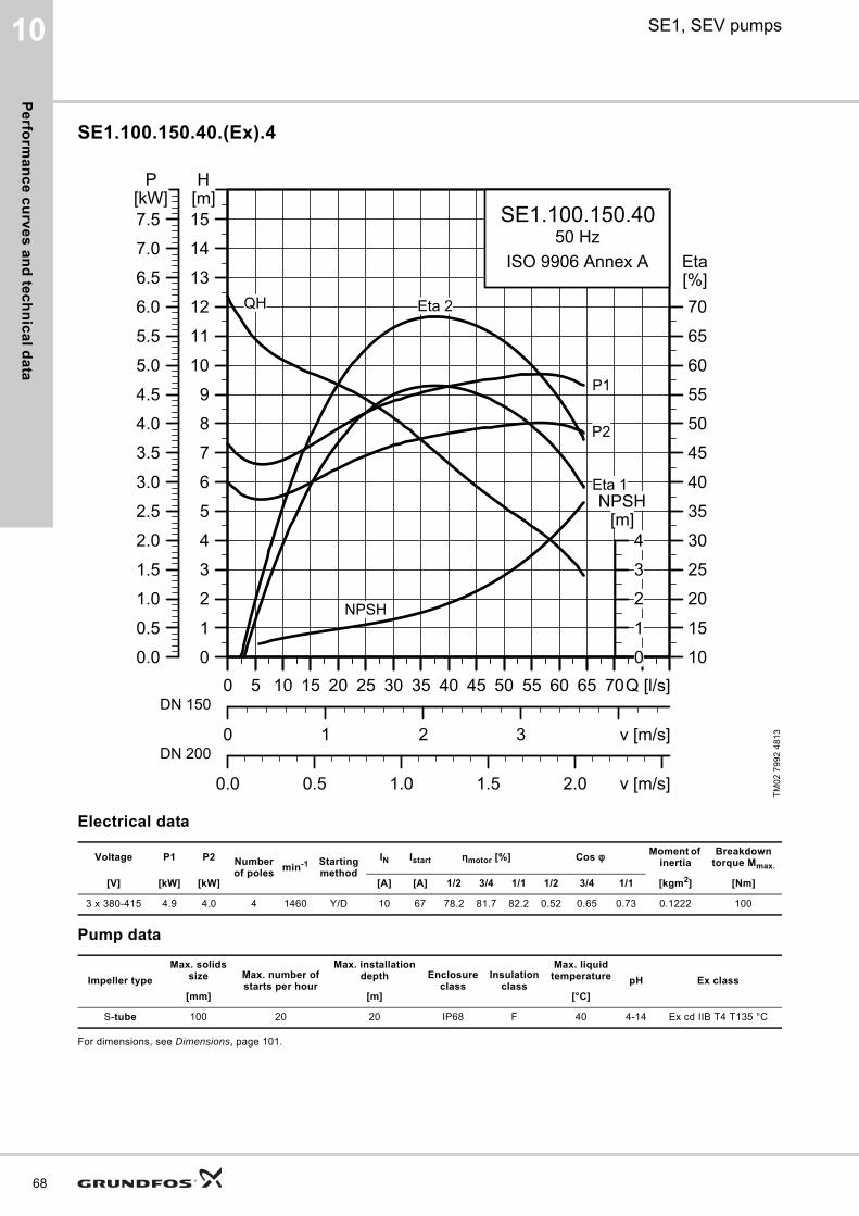
Pe
rform
an
ce
cu
rve
s a
nd
tec
hn
ica
l da
ta
68
10 SE1, SEV pumps
SE1.100.150.40.(Ex).4
Electrical data
Pump data
For dimensions, see Dimensions, page 101.
TM
02
79
92
48
13
Voltage P1 P2 Number of poles
min-1 Starting method
IN Istart ηmotor [%] Cos φ Moment of inertia
Breakdown torque Mmax.
[V] [kW] [kW] [A] [A] 1/2 3/4 1/1 1/2 3/4 1/1 [kgm2] [Nm]
3 x 380-415 4.9 4.0 4 1460 Y/D 10 67 78.2 81.7 82.2 0.52 0.65 0.73 0.1222 100
Impeller type
Max. solids size Max. number of
starts per hour
Max. installation depth Enclosure
classInsulation
class
Max. liquid temperature pH Ex class
[mm] [m] [°C]
S-tube 100 20 20 IP68 F 40 4-14 Ex cd IIB T4 T135 °C
0 5 10 15 20 25 30 35 40 45 50 55 60 65 70Q [l/s]0
1
2
3
4
5
6
7
8
9
10
11
12
13
14
15[m]H
0 1 2 3 v [m/s]
10
15
20
25
30
35
40
45
50
55
60
65
70[%]Eta
0.0 0.5 1.0 1.5 2.0 v [m/s]
SE1.100.150.4050 Hz
ISO 9906 Annex A
QH
Eta 1
Eta 2
P2
P1
NPSH
0 5 10 15 20 25 30 35 40 45 50 55 60 65 70Q [l/s]0.0
0.5
1.0
1.5
2.0
2.5
3.0
3.5
4.0
4.5
5.0
5.5
6.0
6.5
7.0
7.5[kW]
P
0
1
2
3
4[m]
NPSH
DN 150
DN 200
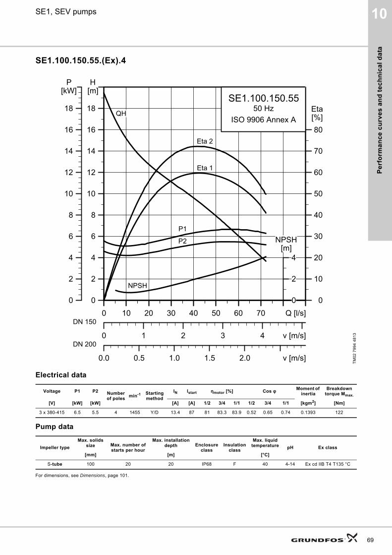
Pe
rfo
rma
nc
e c
urv
es
an
d t
ec
hn
ica
l d
ata
10SE1, SEV pumps
SE1.100.150.55.(Ex).4
Electrical data
Pump data
For dimensions, see Dimensions, page 101.
TM
02
79
94
48
13
Voltage P1 P2 Number of poles
min-1 Starting method
IN Istart ηmotor [%] Cos φ Moment of inertia
Breakdown torque Mmax.
[V] [kW] [kW] [A] [A] 1/2 3/4 1/1 1/2 3/4 1/1 [kgm2] [Nm]
3 x 380-415 6.5 5.5 4 1455 Y/D 13.4 87 81 83.3 83.9 0.52 0.65 0.74 0.1393 122
Impeller type
Max. solids size Max. number of
starts per hour
Max. installation depth Enclosure
classInsulation
class
Max. liquid temperature pH Ex class
[mm] [m] [°C]
S-tube 100 20 20 IP68 F 40 4-14 Ex cd IIB T4 T135 °C
0 10 20 30 40 50 60 70 Q [l/s]0
2
4
6
8
10
12
14
16
18
[m]H
0 1 2 3 4 v [m/s]
0
10
20
30
40
50
60
70
80[%]Eta
0.0 0.5 1.0 1.5 2.0 v [m/s]
SE1.100.150.5550 Hz
ISO 9906 Annex AQH
Eta 1
Eta 2
P2
P1
NPSH
0 10 20 30 40 50 60 70 Q [l/s]0
2
4
6
8
10
12
14
16
18
[kW]P
0
2
4[m]
NPSH
DN 150
DN 200
69
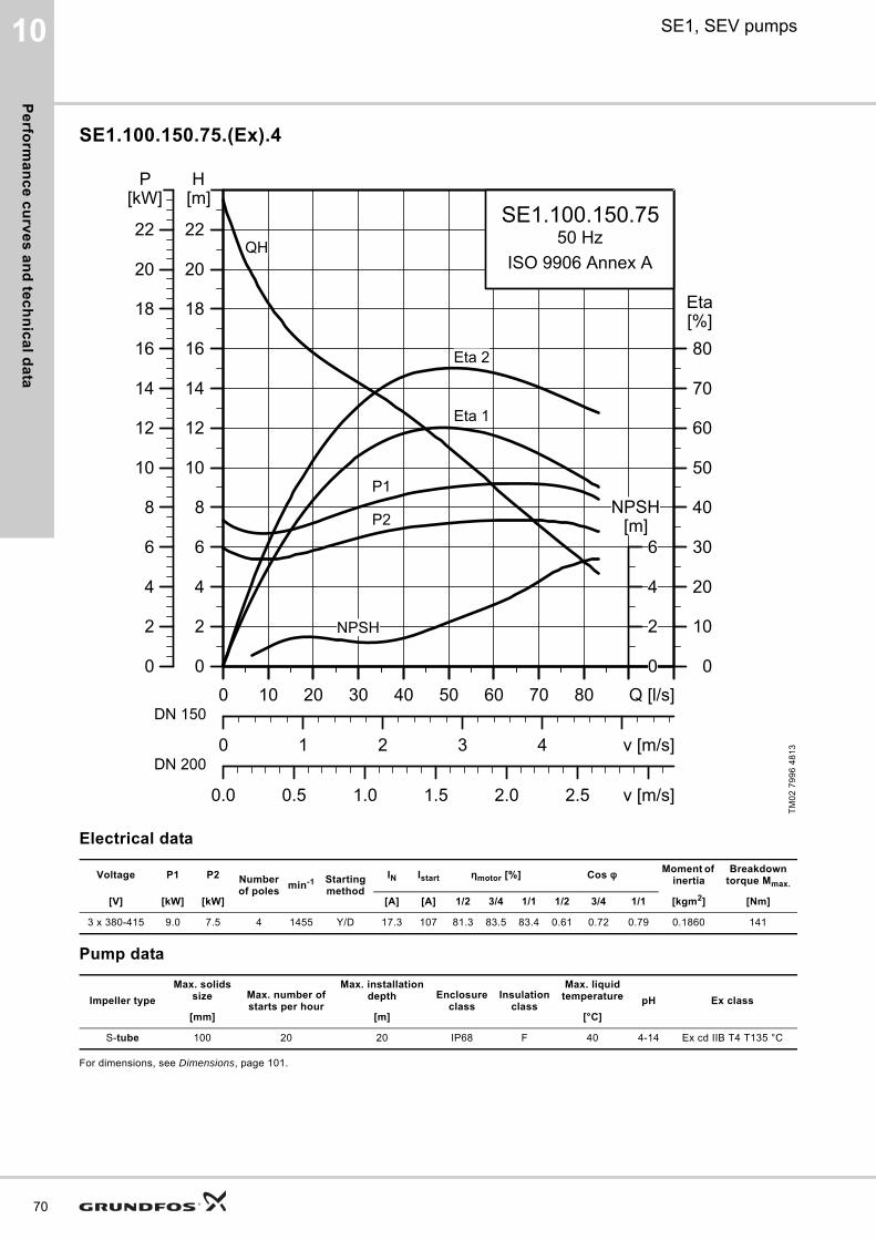
Pe
rform
an
ce
cu
rve
s a
nd
tec
hn
ica
l da
ta
70
10 SE1, SEV pumps
SE1.100.150.75.(Ex).4
Electrical data
Pump data
For dimensions, see Dimensions, page 101.
TM
02
79
96
48
13
Voltage P1 P2 Number of poles
min-1 Starting method
IN Istart ηmotor [%] Cos φ Moment of inertia
Breakdown torque Mmax.
[V] [kW] [kW] [A] [A] 1/2 3/4 1/1 1/2 3/4 1/1 [kgm2] [Nm]
3 x 380-415 9.0 7.5 4 1455 Y/D 17.3 107 81.3 83.5 83.4 0.61 0.72 0.79 0.1860 141
Impeller type
Max. solids size Max. number of
starts per hour
Max. installation depth Enclosure
classInsulation
class
Max. liquid temperature pH Ex class
[mm] [m] [°C]
S-tube 100 20 20 IP68 F 40 4-14 Ex cd IIB T4 T135 °C
0 10 20 30 40 50 60 70 80 Q [l/s]0
2
4
6
8
10
12
14
16
18
20
22
[m]H
0 1 2 3 4 v [m/s]
0
10
20
30
40
50
60
70
80[%]Eta
0.0 0.5 1.0 1.5 2.0 2.5 v [m/s]
SE1.100.150.7550 Hz
ISO 9906 Annex AQH
Eta 1
Eta 2
P2
P1
NPSH
0 10 20 30 40 50 60 70 80 Q [l/s]0
2
4
6
8
10
12
14
16
18
20
22
[kW]P
0
2
4
6[m]
NPSH
DN 150
DN 200
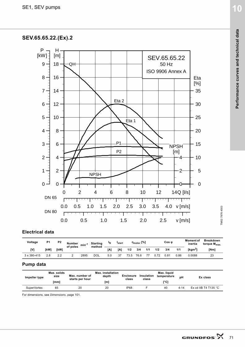
Pe
rfo
rma
nc
e c
urv
es
an
d t
ec
hn
ica
l d
ata
10SE1, SEV pumps
SEV.65.65.22.(Ex).2
Electrical data
Pump data
For dimensions, see Dimensions, page 101.
TM
02
79
76
45
03
Voltage P1 P2 Number of poles
min-1 Starting method
IN Istart ηmotor [%] Cos φ Moment of inertia
Breakdown torque Mmax.
[V] [kW] [kW] [A] [A] 1/2 3/4 1/1 1/2 3/4 1/1 [kgm2] [Nm]
3 x 380-415 2.8 2.2 2 2895 DOL 5.0 37 73.5 76.6 77 0.72 0.81 0.86 0.0088 23
Impeller type
Max. solids size Max. number of
starts per hour
Max. installation depth Enclosure
classInsulation
class
Max. liquid temperature pH Ex class
[mm] [m] [°C]
SuperVortex 65 20 20 IP68 F 40 4-14 Ex cd IIB T4 T135 °C
0 2 4 6 8 10 12 14Q [l/s]
0
2
4
6
8
10
12
14
16
18
[m]H
0.0 0.5 1.0 1.5 2.0 2.5 3.0 3.5 4.0 v [m/s]
0
5
10
15
20
25
30
35
[%]Eta
0.0 0.5 1.0 1.5 2.0 2.5 v [m/s]
SEV.65.65.2250 Hz
ISO 9906 Annex A
Eta 2
Eta 1
QH
P2
P1
NPSH
0 2 4 6 8 10 12 14Q [l/s]
0
1
2
3
4
5
6
7
8
9
[kW]P
0
2
4[m]
NPSH
DN 65
DN 80
71
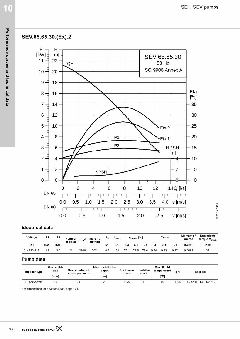
Pe
rform
an
ce
cu
rve
s a
nd
tec
hn
ica
l da
ta
72
10 SE1, SEV pumps
SEV.65.65.30.(Ex).2
Electrical data
Pump data
For dimensions, see Dimensions, page 101.
TM
02
79
77
45
03
Voltage P1 P2 Number of poles
min-1 Starting method
IN Istart ηmotor [%] Cos φ Moment of inertia
Breakdown torque Mmax.
[V] [kW] [kW] [A] [A] 1/2 3/4 1/1 1/2 3/4 1/1 [kgm2] [Nm]
3 x 380-415 3.8 3.0 2 2910 DOL 6.6 51 75.1 78.5 79.6 0.74 0.83 0.87 0.0098 33
Impeller type
Max. solids size Max. number of
starts per hour
Max. installation depth Enclosure
classInsulation
class
Max. liquid temperature pH Ex class
[mm] [m] [°C]
SuperVortex 65 20 20 IP68 F 40 4-14 Ex cd IIB T4 T135 °C
0 2 4 6 8 10 12 14Q [l/s]
0
2
4
6
8
10
12
14
16
18
20
22[m]H
0.0 0.5 1.0 1.5 2.0 2.5 3.0 3.5 4.0 v [m/s]
0
5
10
15
20
25
30
35
[%]Eta
0.0 0.5 1.0 1.5 2.0 2.5 v [m/s]
SEV.65.65.3050 Hz
ISO 9906 Annex A
Eta 2
Eta 1
QH
P2
P1
NPSH
0 2 4 6 8 10 12 14Q [l/s]
0
1
2
3
4
5
6
7
8
9
10
11[kW]
P
0
2
4[m]
NPSH
DN 65
DN 80

Pe
rfo
rma
nc
e c
urv
es
an
d t
ec
hn
ica
l d
ata
10SE1, SEV pumps
SEV.65.65.40.(Ex).2
Electrical data
Pump data
For dimensions, see Dimensions, page 101.
TM
02
79
78
45
03
Voltage P1 P2 Number of poles
min-1 Starting method
IN Istart ηmotor [%] Cos φ Moment of inertia
Breakdown torque Mmax.
[V] [kW] [kW] [A] [A] 1/2 3/4 1/1 1/2 3/4 1/1 [kgm2] [Nm]
3 x 380-415 4.8 4.0 2 2925 Y/D 8.6 71 79.2 82.4 83.3 0.68 0.78 0.84 0.0126 54
Impeller type
Max. solids size Max. number of
starts per hour
Max. installation depth Enclosure
classInsulation
class
Max. liquid temperature pH Ex class
[mm] [m] [°C]
SuperVortex 65 20 20 IP68 F 40 4-14 Ex cd IIB T4 T135 °C
0 2 4 6 8 10 12 14 16 20Q [l/s]
0
4
8
12
16
20
24
28
32
36
[m]H
0 1 2 3 4 5 v [m/s]
0
5
10
15
20
25
30
35
40
[%]Eta
0.0 0.5 1.0 1.5 2.0 2.5 3.0 v [m/s]
SEV.65.65.4050 Hz
ISO 9906 Annex A
Eta 2
Eta 1
QH
P2
P1
NPSH
0 2 4 6 8 10 12 14 16 20Q [l/s]
0
2
4
6
8
10
12
14
16
18
[kW]P
0
4
8[m]
NPSH
DN 65
DN 80
73
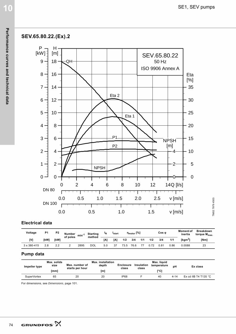
Pe
rform
an
ce
cu
rve
s a
nd
tec
hn
ica
l da
ta
74
10 SE1, SEV pumps
SEV.65.80.22.(Ex).2
Electrical data
Pump data
For dimensions, see Dimensions, page 101.
TM
02
79
79
45
03
Voltage P1 P2 Number of poles
min-1 Starting method
IN Istart ηmotor [%] Cos φ Moment of inertia
Breakdown torque Mmax.
[V] [kW] [kW] [A] [A] 1/2 3/4 1/1 1/2 3/4 1/1 [kgm2] [Nm]
3 x 380-415 2.8 2.2 2 2895 DOL 5.0 37 73.5 76.6 77 0.72 0.81 0.86 0.0088 23
Impeller type
Max. solids size Max. number of
starts per hour
Max. installation depth Enclosure
classInsulation
class
Max. liquid temperature pH Ex class
[mm] [m] [°C]
SuperVortex 65 20 20 IP68 F 40 4-14 Ex cd IIB T4 T135 °C
0 2 4 6 8 10 12 14Q [l/s]
0
2
4
6
8
10
12
14
16
18
[m]H
0.0 0.5 1.0 1.5 2.0 2.5 v [m/s]
0
5
10
15
20
25
30
35
[%]Eta
0.0 0.5 1.0 1.5 v [m/s]
SEV.65.80.2250 Hz
ISO 9906 Annex A
Eta 2
Eta 1
QH
P2
P1
NPSH
0 2 4 6 8 10 12 14Q [l/s]
0
1
2
3
4
5
6
7
8
9
[kW]P
0
2
4[m]
NPSH
DN 80
DN 100
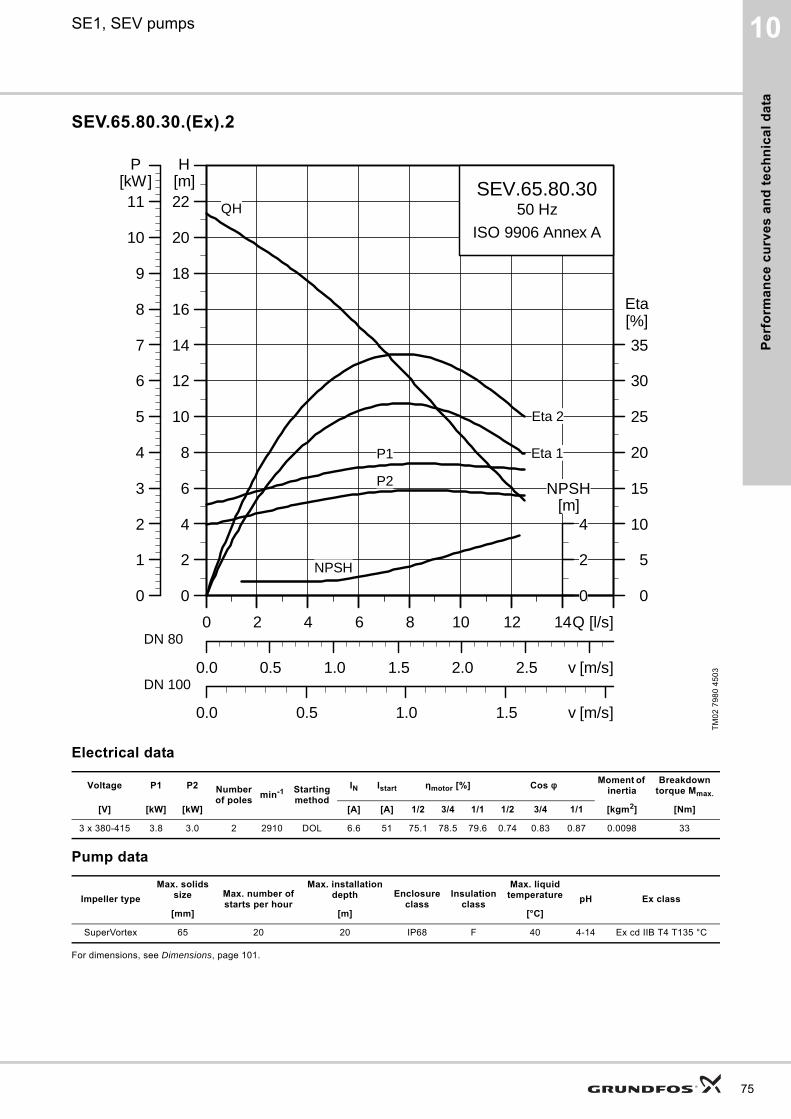
Pe
rfo
rma
nc
e c
urv
es
an
d t
ec
hn
ica
l d
ata
10SE1, SEV pumps
SEV.65.80.30.(Ex).2
Electrical data
Pump data
For dimensions, see Dimensions, page 101.
TM
02
79
80
45
03
Voltage P1 P2 Number of poles
min-1 Starting method
IN Istart ηmotor [%] Cos φ Moment of inertia
Breakdown torque Mmax.
[V] [kW] [kW] [A] [A] 1/2 3/4 1/1 1/2 3/4 1/1 [kgm2] [Nm]
3 x 380-415 3.8 3.0 2 2910 DOL 6.6 51 75.1 78.5 79.6 0.74 0.83 0.87 0.0098 33
Impeller type
Max. solids size Max. number of
starts per hour
Max. installation depth Enclosure
classInsulation
class
Max. liquid temperature pH Ex class
[mm] [m] [°C]
SuperVortex 65 20 20 IP68 F 40 4-14 Ex cd IIB T4 T135 °C
0 2 4 6 8 10 12 14Q [l/s]
0
2
4
6
8
10
12
14
16
18
20
22[m]H
0.0 0.5 1.0 1.5 2.0 2.5 v [m/s]
0
5
10
15
20
25
30
35
[%]Eta
0.0 0.5 1.0 1.5 v [m/s]
SEV.65.80.3050 Hz
ISO 9906 Annex A
Eta 2
Eta 1
QH
P2
P1
NPSH
0 2 4 6 8 10 12 14Q [l/s]
0
1
2
3
4
5
6
7
8
9
10
11[kW]
P
0
2
4[m]
NPSH
DN 80
DN 100
75
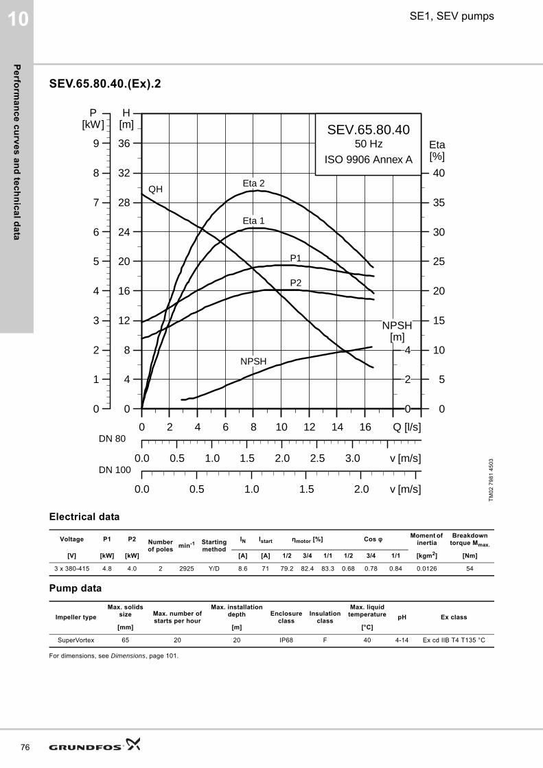
Pe
rform
an
ce
cu
rve
s a
nd
tec
hn
ica
l da
ta
76
10 SE1, SEV pumps
SEV.65.80.40.(Ex).2
Electrical data
Pump data
For dimensions, see Dimensions, page 101.
TM
02
79
81
45
03
Voltage P1 P2 Number of poles
min-1 Starting method
IN Istart ηmotor [%] Cos φ Moment of inertia
Breakdown torque Mmax.
[V] [kW] [kW] [A] [A] 1/2 3/4 1/1 1/2 3/4 1/1 [kgm2] [Nm]
3 x 380-415 4.8 4.0 2 2925 Y/D 8.6 71 79.2 82.4 83.3 0.68 0.78 0.84 0.0126 54
Impeller type
Max. solids size Max. number of
starts per hour
Max. installation depth Enclosure
classInsulation
class
Max. liquid temperature pH Ex class
[mm] [m] [°C]
SuperVortex 65 20 20 IP68 F 40 4-14 Ex cd IIB T4 T135 °C
0 2 4 6 8 10 12 14 16 Q [l/s]
0
4
8
12
16
20
24
28
32
36
[m]H
0.0 0.5 1.0 1.5 2.0 2.5 3.0 v [m/s]
0
5
10
15
20
25
30
35
40
[%]Eta
0.0 0.5 1.0 1.5 2.0 v [m/s]
SEV.65.80.4050 Hz
ISO 9906 Annex A
Eta 2
Eta 1
QH
P2
P1
NPSH
0 2 4 6 8 10 12 14 16 Q [l/s]
0
1
2
3
4
5
6
7
8
9
[kW]P
0
2
4[m]
NPSH
DN 80
DN 100
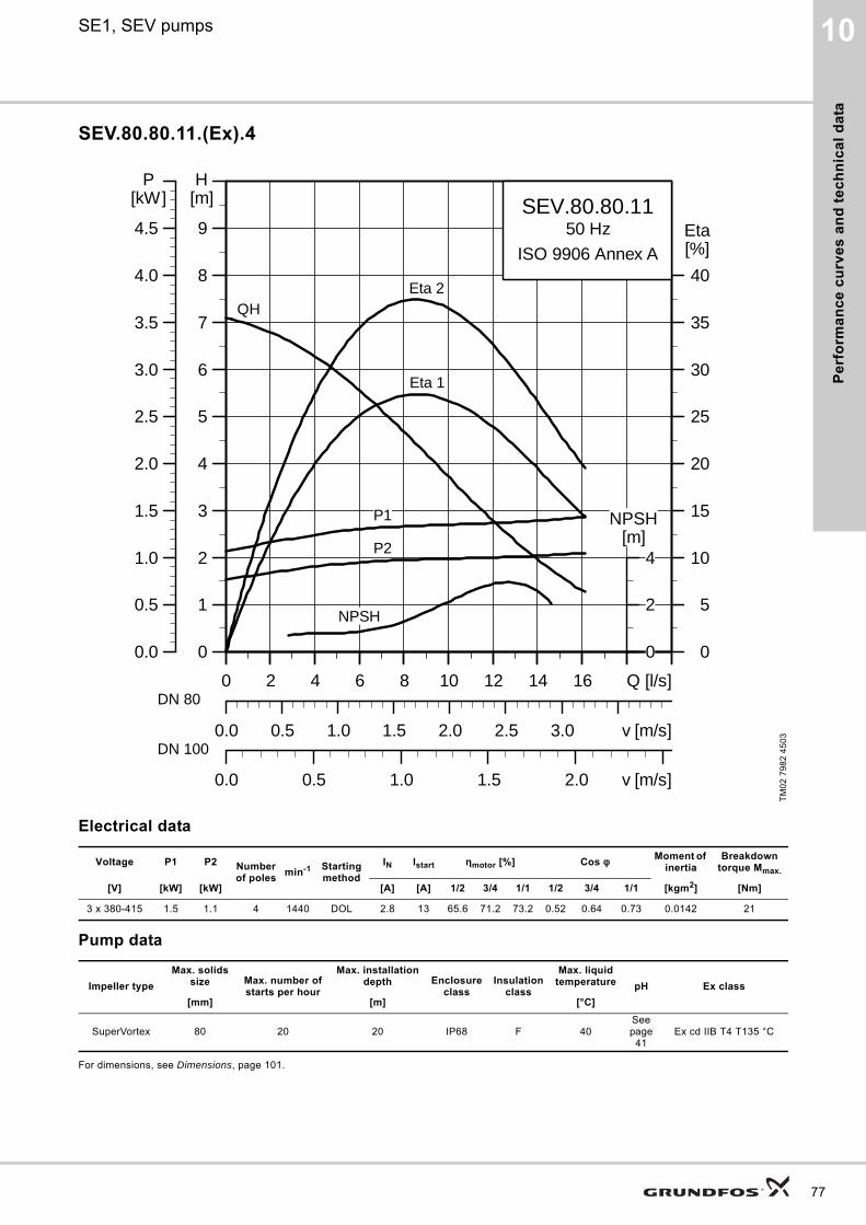
Pe
rfo
rma
nc
e c
urv
es
an
d t
ec
hn
ica
l d
ata
10SE1, SEV pumps
SEV.80.80.11.(Ex).4
Electrical data
Pump data
For dimensions, see Dimensions, page 101.
TM
02
79
82
45
03
Voltage P1 P2 Number of poles
min-1 Starting method
IN Istart ηmotor [%] Cos φ Moment of inertia
Breakdown torque Mmax.
[V] [kW] [kW] [A] [A] 1/2 3/4 1/1 1/2 3/4 1/1 [kgm2] [Nm]
3 x 380-415 1.5 1.1 4 1440 DOL 2.8 13 65.6 71.2 73.2 0.52 0.64 0.73 0.0142 21
Impeller type
Max. solids size Max. number of
starts per hour
Max. installation depth Enclosure
classInsulation
class
Max. liquid temperature pH Ex class
[mm] [m] [°C]
SuperVortex 80 20 20 IP68 F 40See page
41Ex cd IIB T4 T135 °C
0 2 4 6 8 10 12 14 16 Q [l/s]
0
1
2
3
4
5
6
7
8
9
[m]H
0.0 0.5 1.0 1.5 2.0 2.5 3.0 v [m/s]
0
5
10
15
20
25
30
35
40
[%]Eta
0.0 0.5 1.0 1.5 2.0 v [m/s]
SEV.80.80.1150 Hz
ISO 9906 Annex A
Eta 2
Eta 1
QH
P2
P1
NPSH
0 2 4 6 8 10 12 14 16 Q [l/s]
0.0
0.5
1.0
1.5
2.0
2.5
3.0
3.5
4.0
4.5
[kW]P
0
2
4[m]
NPSH
DN 80
DN 100
77
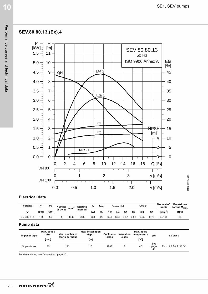
Pe
rform
an
ce
cu
rve
s a
nd
tec
hn
ica
l da
ta
78
10 SE1, SEV pumps
SEV.80.80.13.(Ex).4
Electrical data
Pump data
For dimensions, see Dimensions, page 101.
TM
02
79
72
45
03
Voltage P1 P2 Number of poles
min-1 Starting method
IN Istart ηmotor [%] Cos φ Moment of inertia
Breakdown torque Mmax.
[V] [kW] [kW] [A] [A] 1/2 3/4 1/1 1/2 3/4 1/1 [kgm2] [Nm]
3 x 380-415 1.8 1.3 4 1440 DOL 3.8 22 63.9 69.6 71.7 0.51 0.63 0.72 0.0165 28
Impeller type
Max. solids size Max. number of
starts per hour
Max. installation depth Enclosure
classInsulation
class
Max. liquid temperature pH Ex class
[mm] [m] [°C]
SuperVortex 80 20 20 IP68 F 40See page
41Ex cd IIB T4 T135 °C
0 2 4 6 8 10 12 14 16 18 Q [l/s]
0
1
2
3
4
5
6
7
8
9
10
11[m]H
0 1 2 3 v [m/s]
0
5
10
15
20
25
30
35
40
45
[%]Eta
0.0 0.5 1.0 1.5 2.0 v [m/s]
SEV.80.80.1350 Hz
ISO 9906 Annex A
QH
Eta 1
Eta 2
P2
P1
NPSH
0 2 4 6 8 10 12 14 16 18 Q [l/s]
0.0
0.5
1.0
1.5
2.0
2.5
3.0
3.5
4.0
4.5
5.0
5.5[kW]
P
0
2
4[m]
NPSH
DN 80
DN 100
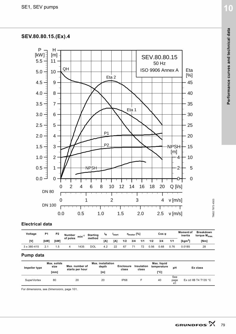
Pe
rfo
rma
nc
e c
urv
es
an
d t
ec
hn
ica
l d
ata
10SE1, SEV pumps
SEV.80.80.15.(Ex).4
Electrical data
Pump data
For dimensions, see Dimensions, page 101.
TM
02
79
73
45
03
Voltage P1 P2 Number of poles
min-1 Starting method
IN Istart ηmotor [%] Cos φ Moment of inertia
Breakdown torque Mmax.
[V] [kW] [kW] [A] [A] 1/2 3/4 1/1 1/2 3/4 1/1 [kgm2] [Nm]
3 x 380-415 2.1 1.5 4 1435 DOL 4.2 22 67 71 72 0.56 0.68 0.76 0.0185 28
Impeller type
Max. solids size Max. number of
starts per hour
Max. installation depth Enclosure
classInsulation
class
Max. liquid temperature pH Ex class
[mm] [m] [°C]
SuperVortex 80 20 20 IP68 F 40See page
41Ex cd IIB T4 T135 °C
0 2 4 6 8 10 12 14 16 18 20 Q [l/s]
0
1
2
3
4
5
6
7
8
9
10
11[m]H
0 1 2 3 4 v [m/s]
0
5
10
15
20
25
30
35
40
45
[%]Eta
0.0 0.5 1.0 1.5 2.0 2.5 v [m/s]
SEV.80.80.1550 Hz
ISO 9906 Annex AQH
Eta 1
Eta 2
P2
P1
NPSH
0 2 4 6 8 10 12 14 16 18 20 Q [l/s]
0.0
0.5
1.0
1.5
2.0
2.5
3.0
3.5
4.0
4.5
5.0
5.5[kW]
P
0
2
4[m]
NPSH
DN 80
DN 100
79
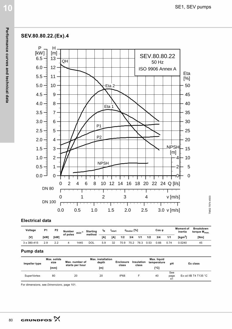
Pe
rform
an
ce
cu
rve
s a
nd
tec
hn
ica
l da
ta
80
10 SE1, SEV pumps
SEV.80.80.22.(Ex).4
Electrical data
Pump data
For dimensions, see Dimensions, page 101.
TM
02
79
74
45
03
Voltage P1 P2 Number of poles
min-1 Starting method
IN Istart ηmotor [%] Cos φ Moment of inertia
Breakdown torque Mmax.
[V] [kW] [kW] [A] [A] 1/2 3/4 1/1 1/2 3/4 1/1 [kgm2] [Nm]
3 x 380-415 2.9 2.2 4 1445 DOL 5.9 32 70.9 75.2 76.3 0.53 0.66 0.74 0.0240 45
Impeller type
Max. solids size Max. number of
starts per hour
Max. installation depth Enclosure
classInsulation
class
Max. liquid temperature pH Ex class
[mm] [m] [°C]
SuperVortex 80 20 20 IP68 F 40See page
41Ex cd IIB T4 T135 °C
0 2 4 6 8 10 12 14 16 18 20 22 24 Q [l/s]
0
1
2
3
4
5
6
7
8
9
10
11
12
13[m]H
0 1 2 3 4 v [m/s]
0
5
10
15
20
25
30
35
40
45
50
[%]Eta
0.0 0.5 1.0 1.5 2.0 2.5 3.0 v [m/s]
SEV.80.80.2250 Hz
ISO 9906 Annex A
QH
Eta 1
Eta 2
P2
P1
NPSH
0 2 4 6 8 10 12 14 16 18 20 22 24 Q [l/s]
0.0
0.5
1.0
1.5
2.0
2.5
3.0
3.5
4.0
4.5
5.0
5.5
6.0
6.5[kW]
P
0
2
4[m]
NPSH
DN 80
DN 100

Pe
rfo
rma
nc
e c
urv
es
an
d t
ec
hn
ica
l d
ata
10SE1, SEV pumps
SEV.80.80.40.(Ex).4
Electrical data
Pump data
For dimensions, see Dimensions, page 101.
TM
02
79
75
45
03
Voltage P1 P2 Number of poles
min-1 Starting method
IN Istart ηmotor [%] Cos φ Moment of inertia
Breakdown torque Mmax.
[V] [kW] [kW] [A] [A] 1/2 3/4 1/1 1/2 3/4 1/1 [kgm2] [Nm]
3 x 380-415 4.9 4.0 4 1460 Y/D 10 67 78.2 81.7 82.2 0.52 0.65 0.73 0.0479 100
Impeller type
Max. solids size Max. number of
starts per hour
Max. installation depth Enclosure
classInsulation
class
Max. liquid temperature pH Ex class
[mm] [m] [°C]
SuperVortex 80 20 20 IP68 F 40 4-10 Ex cd IIB T4 T135 °C
0 4 8 12 16 20 24 28Q [l/s]
0
2
4
6
8
10
12
14
16
18
20
22
[m]H
0 1 2 3 4 5 v [m/s]
0
5
10
15
20
25
30
35
40
45
[%]Eta
0.0 0.5 1.0 1.5 2.0 2.5 3.0 3.5v [m/s]
SEV.80.80.40.450 Hz
ISO 9906 Annex A
QH
Eta 1
Eta 2
P2
P1
NPSH
0 4 8 12 16 20 24 28Q [l/s]
0
1
2
3
4
5
6
7
8
9
10
11
[kW]P
0
2
4
6[m]
NPSH
DN 80
DN 100
81
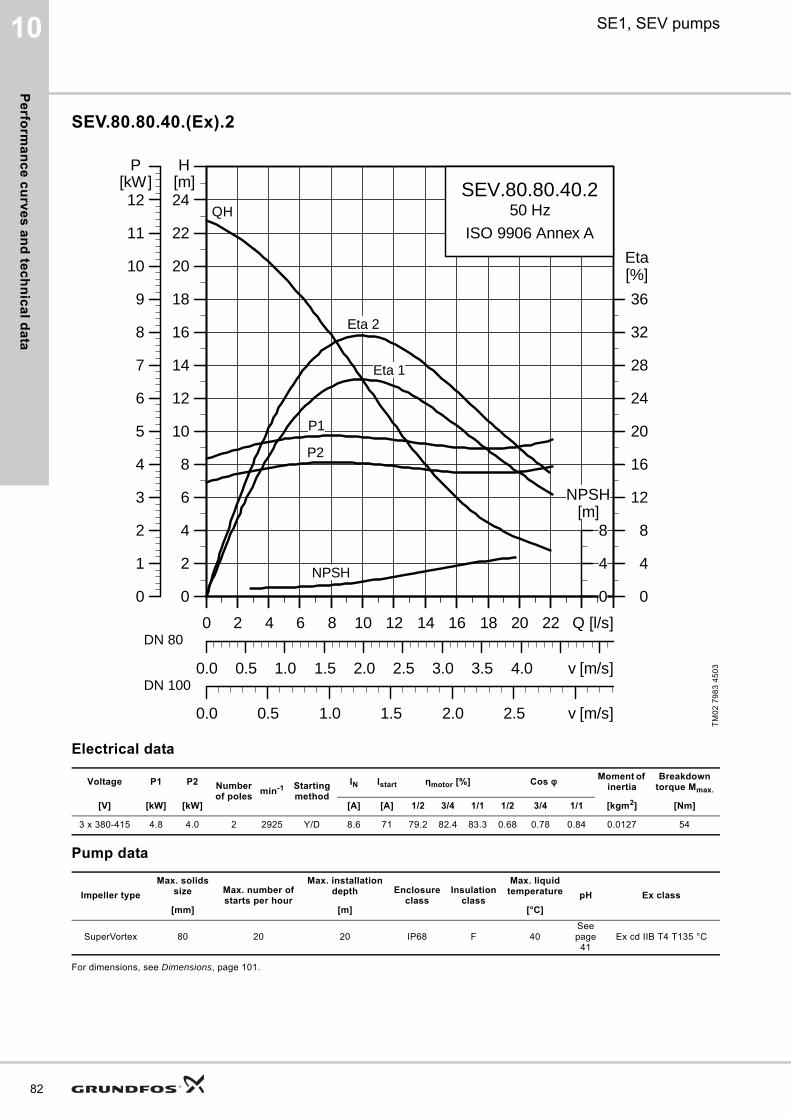
Pe
rform
an
ce
cu
rve
s a
nd
tec
hn
ica
l da
ta
82
10 SE1, SEV pumps
SEV.80.80.40.(Ex).2
Electrical data
Pump data
For dimensions, see Dimensions, page 101.
TM
02
79
83
45
03
Voltage P1 P2 Number of poles
min-1 Starting method
IN Istart ηmotor [%] Cos φ Moment of inertia
Breakdown torque Mmax.
[V] [kW] [kW] [A] [A] 1/2 3/4 1/1 1/2 3/4 1/1 [kgm2] [Nm]
3 x 380-415 4.8 4.0 2 2925 Y/D 8.6 71 79.2 82.4 83.3 0.68 0.78 0.84 0.0127 54
Impeller type
Max. solids size Max. number of
starts per hour
Max. installation depth Enclosure
classInsulation
class
Max. liquid temperature pH Ex class
[mm] [m] [°C]
SuperVortex 80 20 20 IP68 F 40See page
41Ex cd IIB T4 T135 °C
0 2 4 6 8 10 12 14 16 18 20 22 Q [l/s]
0
2
4
6
8
10
12
14
16
18
20
22
24[m]H
0.0 0.5 1.0 1.5 2.0 2.5 3.0 3.5 4.0 v [m/s]
0
4
8
12
16
20
24
28
32
36
[%]Eta
0.0 0.5 1.0 1.5 2.0 2.5 v [m/s]
SEV.80.80.40.250 Hz
ISO 9906 Annex A
Eta 2
Eta 1
QH
P2
P1
NPSH
0 2 4 6 8 10 12 14 16 18 20 22 Q [l/s]
0
1
2
3
4
5
6
7
8
9
10
11
12[kW]
P
0
4
8[m]
NPSH
DN 80
DN 100
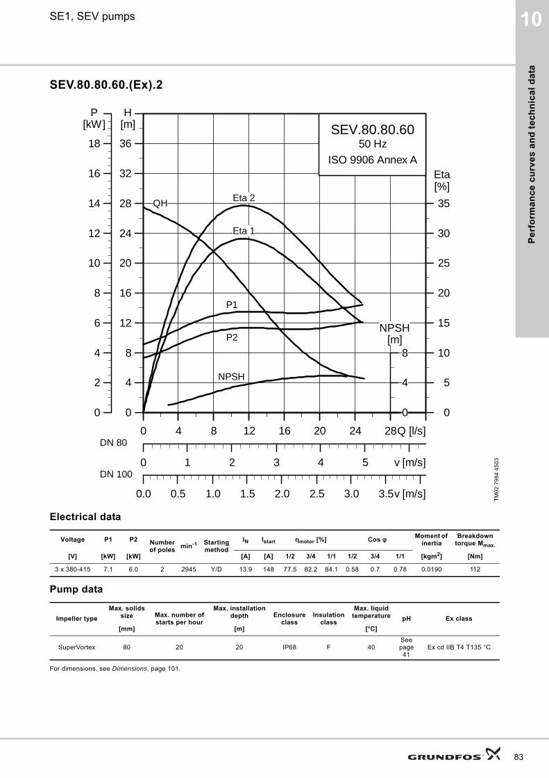
Pe
rfo
rma
nc
e c
urv
es
an
d t
ec
hn
ica
l d
ata
10SE1, SEV pumps
SEV.80.80.60.(Ex).2
Electrical data
Pump data
For dimensions, see Dimensions, page 101.
TM
02
79
84
45
03
Voltage P1 P2 Number of poles
min-1 Starting method
IN Istart ηmotor [%] Cos φ Moment of inertia
Breakdown torque Mmax.
[V] [kW] [kW] [A] [A] 1/2 3/4 1/1 1/2 3/4 1/1 [kgm2] [Nm]
3 x 380-415 7.1 6.0 2 2945 Y/D 13.9 148 77.5 82.2 84.1 0.58 0.7 0.78 0.0190 112
Impeller type
Max. solids size Max. number of
starts per hour
Max. installation depth Enclosure
classInsulation
class
Max. liquid temperature pH Ex class
[mm] [m] [°C]
SuperVortex 80 20 20 IP68 F 40See page
41Ex cd IIB T4 T135 °C
0 4 8 12 16 20 24 28Q [l/s]
0
4
8
12
16
20
24
28
32
36
[m]H
0 1 2 3 4 5 v [m/s]
0
5
10
15
20
25
30
35
[%]Eta
0.0 0.5 1.0 1.5 2.0 2.5 3.0 3.5v [m/s]
SEV.80.80.6050 Hz
ISO 9906 Annex A
Eta 2
Eta 1
QH
P2
P1
NPSH
0 4 8 12 16 20 24 28Q [l/s]
0
2
4
6
8
10
12
14
16
18
[kW]P
0
4
8[m]
NPSH
DN 80
DN 100
83
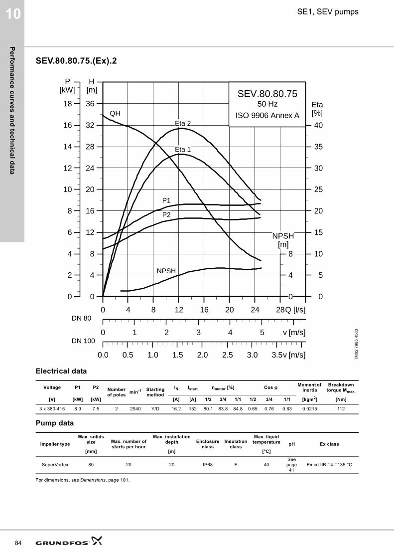
Pe
rform
an
ce
cu
rve
s a
nd
tec
hn
ica
l da
ta
84
10 SE1, SEV pumps
SEV.80.80.75.(Ex).2
Electrical data
Pump data
For dimensions, see Dimensions, page 101.
TM
02
79
85
45
03
Voltage P1 P2 Number of poles
min-1 Starting method
IN Istart ηmotor [%] Cos φ Moment of inertia
Breakdown torque Mmax.
[V] [kW] [kW] [A] [A] 1/2 3/4 1/1 1/2 3/4 1/1 [kgm2] [Nm]
3 x 380-415 8.9 7.5 2 2940 Y/D 16.2 152 80.1 83.8 84.8 0.65 0.76 0.83 0.0215 112
Impeller type
Max. solids size Max. number of
starts per hour
Max. installation depth Enclosure
classInsulation
class
Max. liquid temperature pH Ex class
[mm] [m] [°C]
SuperVortex 80 20 20 IP68 F 40See page
41Ex cd IIB T4 T135 °C
0 4 8 12 16 20 24 28Q [l/s]
0
4
8
12
16
20
24
28
32
36
[m]H
0 1 2 3 4 5 v [m/s]
0
5
10
15
20
25
30
35
40
[%]Eta
0.0 0.5 1.0 1.5 2.0 2.5 3.0 3.5v [m/s]
SEV.80.80.7550 Hz
ISO 9906 Annex AEta 2
Eta 1
QH
P2
P1
NPSH
0 4 8 12 16 20 24 28Q [l/s]
0
2
4
6
8
10
12
14
16
18
[kW]P
0
4
8[m]
NPSH
DN 80
DN 100
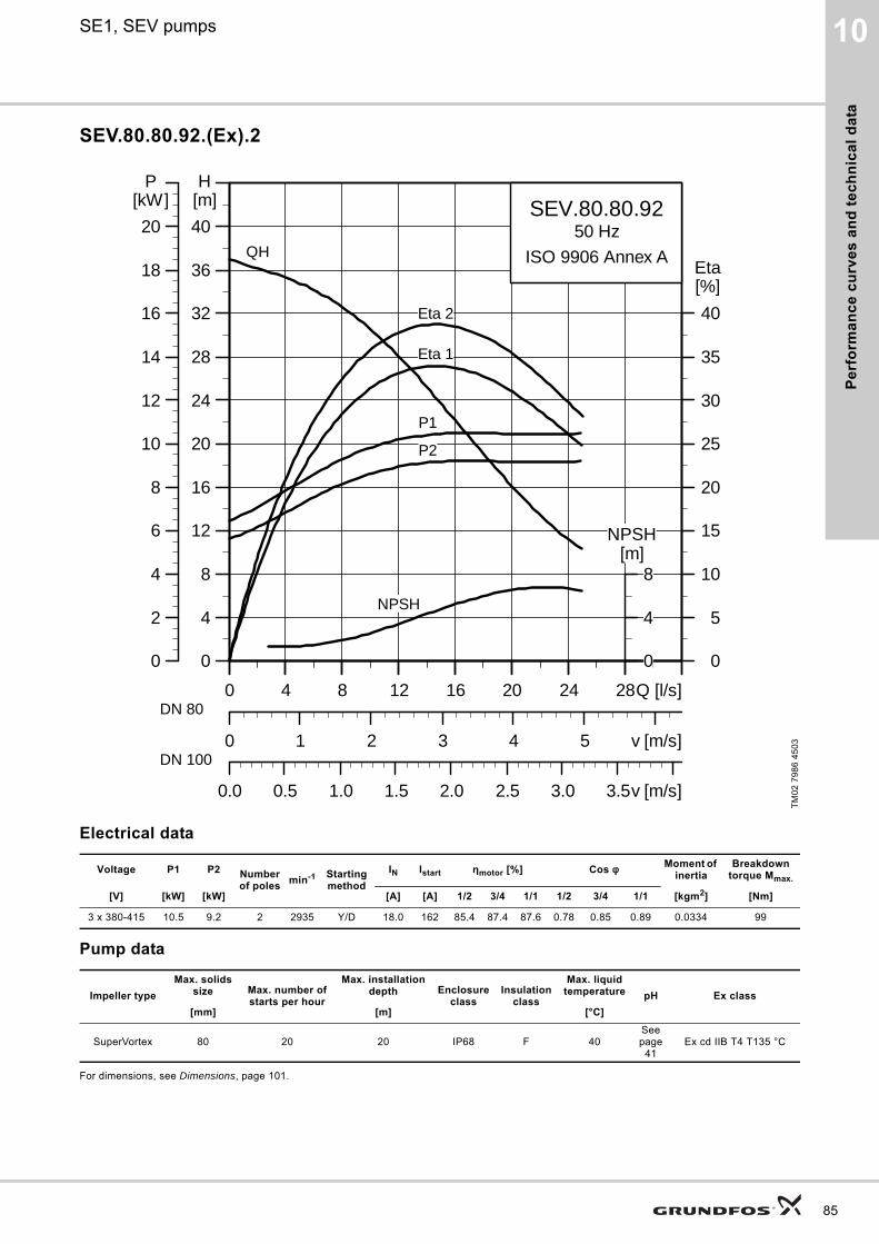
Pe
rfo
rma
nc
e c
urv
es
an
d t
ec
hn
ica
l d
ata
10SE1, SEV pumps
SEV.80.80.92.(Ex).2
Electrical data
Pump data
For dimensions, see Dimensions, page 101.
TM
02
79
86
45
03
Voltage P1 P2 Number of poles
min-1 Starting method
IN Istart ηmotor [%] Cos φ Moment of inertia
Breakdown torque Mmax.
[V] [kW] [kW] [A] [A] 1/2 3/4 1/1 1/2 3/4 1/1 [kgm2] [Nm]
3 x 380-415 10.5 9.2 2 2935 Y/D 18.0 162 85.4 87.4 87.6 0.78 0.85 0.89 0.0334 99
Impeller type
Max. solids size Max. number of
starts per hour
Max. installation depth Enclosure
classInsulation
class
Max. liquid temperature pH Ex class
[mm] [m] [°C]
SuperVortex 80 20 20 IP68 F 40See page
41Ex cd IIB T4 T135 °C
0 4 8 12 16 20 24 28Q [l/s]
0
4
8
12
16
20
24
28
32
36
40
[m]H
0 1 2 3 4 5 v [m/s]
0
5
10
15
20
25
30
35
40
[%]Eta
0.0 0.5 1.0 1.5 2.0 2.5 3.0 3.5v [m/s]
SEV.80.80.9250 Hz
ISO 9906 Annex A
Eta 2
Eta 1
QH
P2
P1
NPSH
0 4 8 12 16 20 24 28Q [l/s]
0
2
4
6
8
10
12
14
16
18
20
[kW]P
0
4
8[m]
NPSH
DN 80
DN 100
85
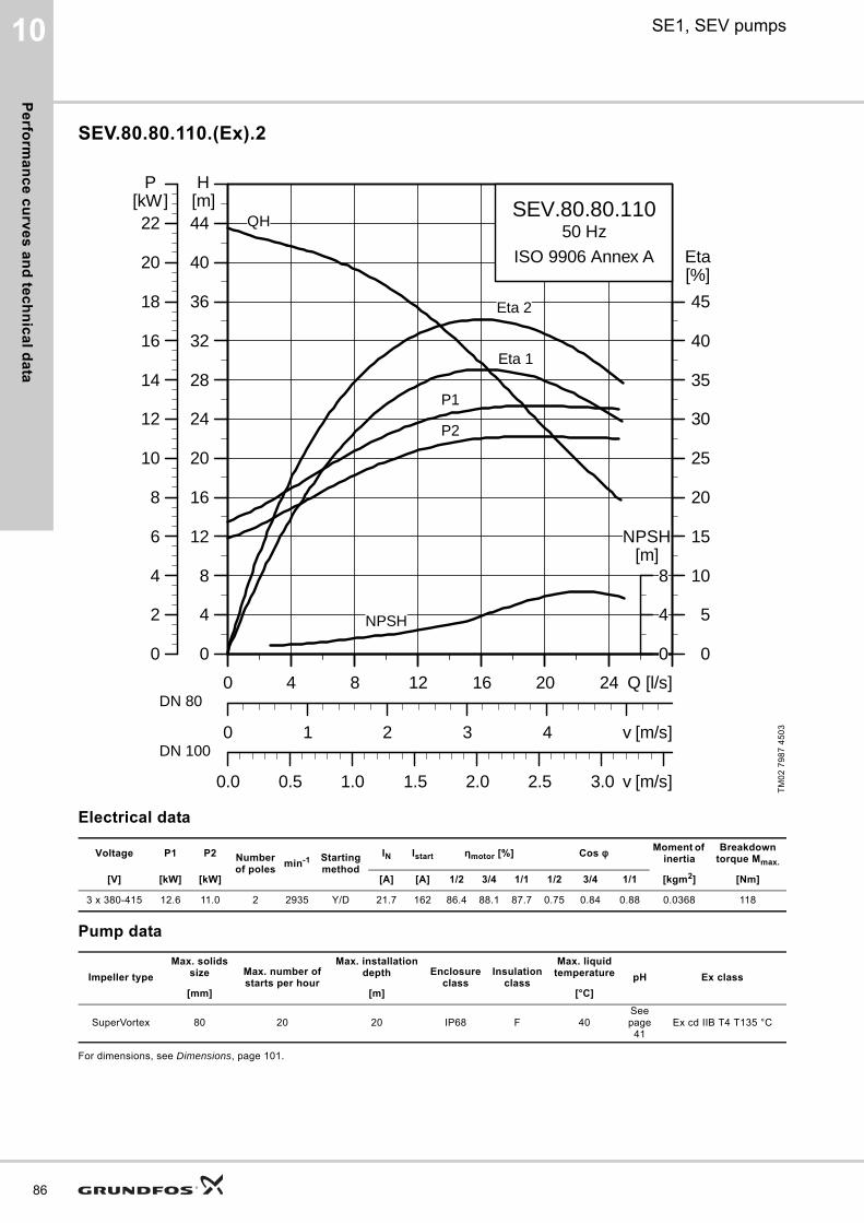
Pe
rform
an
ce
cu
rve
s a
nd
tec
hn
ica
l da
ta
86
10 SE1, SEV pumps
SEV.80.80.110.(Ex).2
Electrical data
Pump data
For dimensions, see Dimensions, page 101.
TM
02
79
87
45
03
Voltage P1 P2 Number of poles
min-1 Starting method
IN Istart ηmotor [%] Cos φ Moment of inertia
Breakdown torque Mmax.
[V] [kW] [kW] [A] [A] 1/2 3/4 1/1 1/2 3/4 1/1 [kgm2] [Nm]
3 x 380-415 12.6 11.0 2 2935 Y/D 21.7 162 86.4 88.1 87.7 0.75 0.84 0.88 0.0368 118
Impeller type
Max. solids size Max. number of
starts per hour
Max. installation depth Enclosure
classInsulation
class
Max. liquid temperature pH Ex class
[mm] [m] [°C]
SuperVortex 80 20 20 IP68 F 40See page
41Ex cd IIB T4 T135 °C
0 4 8 12 16 20 24 Q [l/s]
0
4
8
12
16
20
24
28
32
36
40
44[m]H
0 1 2 3 4 v [m/s]
0
5
10
15
20
25
30
35
40
45
[%]Eta
0.0 0.5 1.0 1.5 2.0 2.5 3.0 v [m/s]
SEV.80.80.11050 Hz
ISO 9906 Annex A
Eta 2
Eta 1
QH
P2
P1
NPSH
0 4 8 12 16 20 24 Q [l/s]
0
2
4
6
8
10
12
14
16
18
20
22[kW]
P
0
4
8[m]
NPSH
DN 80
DN 100
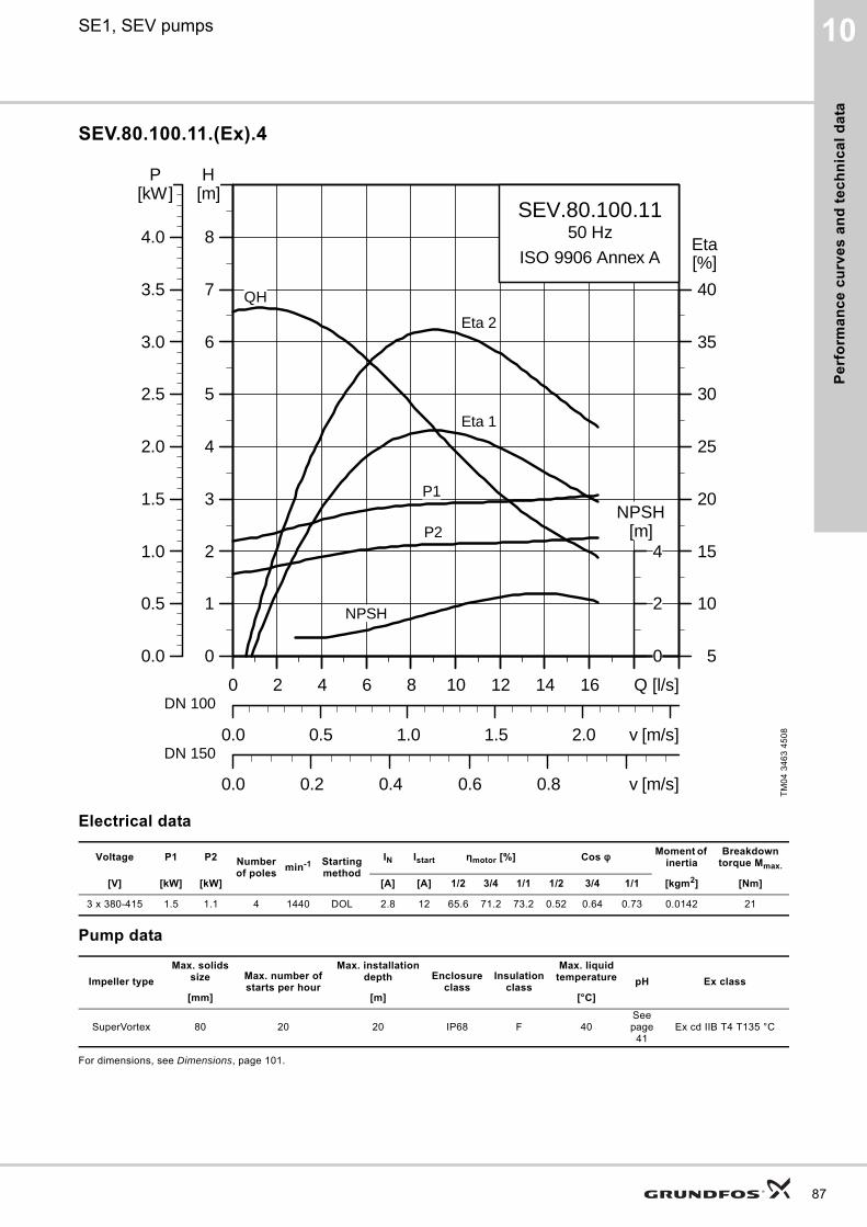
Pe
rfo
rma
nc
e c
urv
es
an
d t
ec
hn
ica
l d
ata
10SE1, SEV pumps
SEV.80.100.11.(Ex).4
Electrical data
Pump data
For dimensions, see Dimensions, page 101.
TM
04
34
63
45
08
Voltage P1 P2 Number of poles
min-1 Starting method
IN Istart ηmotor [%] Cos φ Moment of inertia
Breakdown torque Mmax.
[V] [kW] [kW] [A] [A] 1/2 3/4 1/1 1/2 3/4 1/1 [kgm2] [Nm]
3 x 380-415 1.5 1.1 4 1440 DOL 2.8 12 65.6 71.2 73.2 0.52 0.64 0.73 0.0142 21
Impeller type
Max. solids size Max. number of
starts per hour
Max. installation depth Enclosure
classInsulation
class
Max. liquid temperature pH Ex class
[mm] [m] [°C]
SuperVortex 80 20 20 IP68 F 40See page
41Ex cd IIB T4 T135 °C
0 2 4 6 8 10 12 14 16 Q [l/s]
0
1
2
3
4
5
6
7
8
[m]H
0.0 0.5 1.0 1.5 2.0 v [m/s]
5
10
15
20
25
30
35
40
[%]Eta
0.0 0.2 0.4 0.6 0.8 v [m/s]
SEV.80.100.1150 Hz
ISO 9906 Annex A
Eta 2
Eta 1
QH
P2
P1
NPSH
0 2 4 6 8 10 12 14 16 Q [l/s]
0.0
0.5
1.0
1.5
2.0
2.5
3.0
3.5
4.0
[kW]P
0
2
4[m]
NPSH
DN 100
DN 150
87
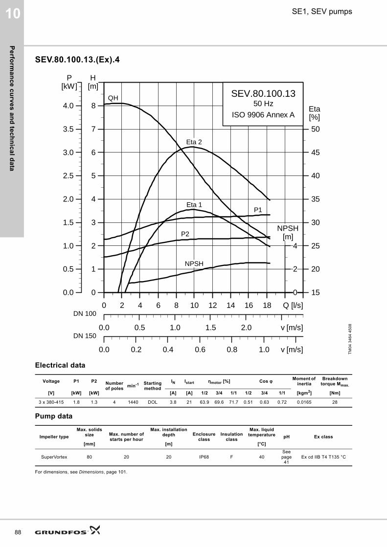
Pe
rform
an
ce
cu
rve
s a
nd
tec
hn
ica
l da
ta
88
10 SE1, SEV pumps
SEV.80.100.13.(Ex).4
Electrical data
Pump data
For dimensions, see Dimensions, page 101.
TM
04
34
64
45
08
Voltage P1 P2 Number of poles
min-1 Starting method
IN Istart ηmotor [%] Cos φ Moment of inertia
Breakdown torque Mmax.
[V] [kW] [kW] [A] [A] 1/2 3/4 1/1 1/2 3/4 1/1 [kgm2] [Nm]
3 x 380-415 1.8 1.3 4 1440 DOL 3.8 21 63.9 69.6 71.7 0.51 0.63 0.72 0.0165 28
Impeller type
Max. solids size Max. number of
starts per hour
Max. installation depth Enclosure
classInsulation
class
Max. liquid temperature pH Ex class
[mm] [m] [°C]
SuperVortex 80 20 20 IP68 F 40See page
41Ex cd IIB T4 T135 °C
0 2 4 6 8 10 12 14 16 18 Q [l/s]
0
1
2
3
4
5
6
7
8
[m]H
0.0 0.5 1.0 1.5 2.0 v [m/s]
15
20
25
30
35
40
45
50
[%]Eta
0.0 0.2 0.4 0.6 0.8 1.0 v [m/s]
SEV.80.100.1350 Hz
ISO 9906 Annex A
QH
Eta 2
Eta 1
P2
P1
NPSH
0 2 4 6 8 10 12 14 16 18 Q [l/s]
0.0
0.5
1.0
1.5
2.0
2.5
3.0
3.5
4.0
[kW]P
0
2
4[m]
NPSH
DN 100
DN 150
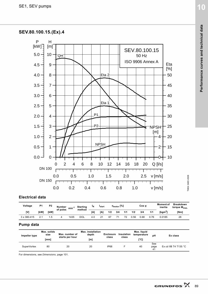
Pe
rfo
rma
nc
e c
urv
es
an
d t
ec
hn
ica
l d
ata
10SE1, SEV pumps
SEV.80.100.15.(Ex).4
Electrical data
Pump data
For dimensions, see Dimensions, page 101.
TM
04
34
65
45
08
Voltage P1 P2 Number of poles
min-1 Starting method
IN Istart ηmotor [%] Cos φ Moment of inertia
Breakdown torque Mmax.
[V] [kW] [kW] [A] [A] 1/2 3/4 1/1 1/2 3/4 1/1 [kgm2] [Nm]
3 x 380-415 2.1 1.5 4 1435 DOL 4.0 21 67 71 72 0.56 0.68 0.76 0.0185 28
Impeller type
Max. solids size Max. number of
starts per hour
Max. installation depth Enclosure
classInsulation
class
Max. liquid temperature pH Ex class
[mm] [m] [°C]
SuperVortex 80 20 20 IP68 F 40See page
41Ex cd IIB T4 T135 °C
0 2 4 6 8 10 12 14 16 18 20 Q [l/s]
0
1
2
3
4
5
6
7
8
9
10
[m]H
0.0 0.5 1.0 1.5 2.0 2.5 v [m/s]
10
15
20
25
30
35
40
45
50
[%]Eta
0.0 0.2 0.4 0.6 0.8 1.0 v [m/s]
SEV.80.100.1550 Hz
ISO 9906 Annex A
QH
Eta 2
Eta 1
P2
P1
NPSH
0 2 4 6 8 10 12 14 16 18 20 Q [l/s]
0.0
0.5
1.0
1.5
2.0
2.5
3.0
3.5
4.0
4.5
5.0
[kW]P
0
2
4[m]
NPSH
DN 100
DN 150
89
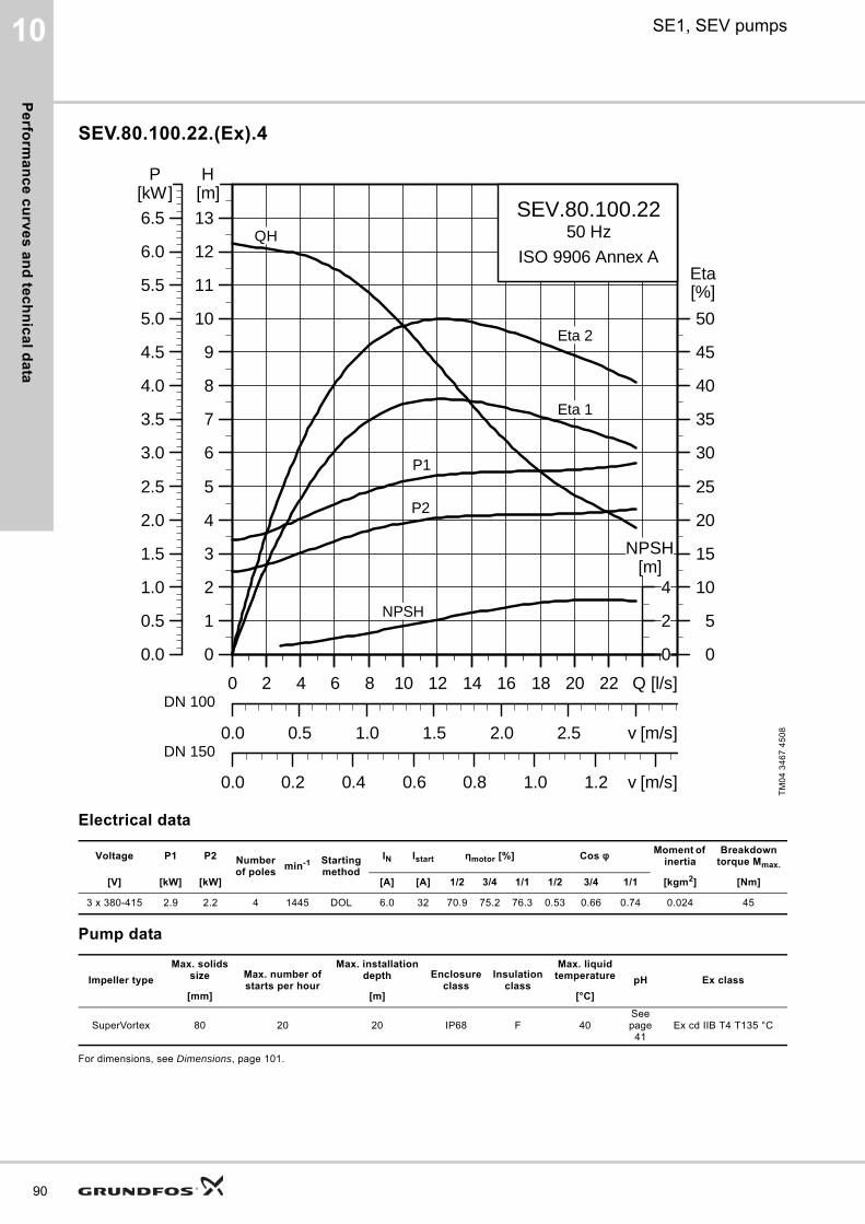
Pe
rform
an
ce
cu
rve
s a
nd
tec
hn
ica
l da
ta
90
10 SE1, SEV pumps
SEV.80.100.22.(Ex).4
Electrical data
Pump data
For dimensions, see Dimensions, page 101.
TM
04
34
67
45
08
Voltage P1 P2 Number of poles
min-1 Starting method
IN Istart ηmotor [%] Cos φ Moment of inertia
Breakdown torque Mmax.
[V] [kW] [kW] [A] [A] 1/2 3/4 1/1 1/2 3/4 1/1 [kgm2] [Nm]
3 x 380-415 2.9 2.2 4 1445 DOL 6.0 32 70.9 75.2 76.3 0.53 0.66 0.74 0.024 45
Impeller type
Max. solids size Max. number of
starts per hour
Max. installation depth Enclosure
classInsulation
class
Max. liquid temperature pH Ex class
[mm] [m] [°C]
SuperVortex 80 20 20 IP68 F 40See page
41Ex cd IIB T4 T135 °C
0 2 4 6 8 10 12 14 16 18 20 22 Q [l/s]
0
1
2
3
4
5
6
7
8
9
10
11
12
13
[m]H
0.0 0.5 1.0 1.5 2.0 2.5 v [m/s]
0
5
10
15
20
25
30
35
40
45
50
[%]Eta
0.0 0.2 0.4 0.6 0.8 1.0 1.2 v [m/s]
SEV.80.100.2250 Hz
ISO 9906 Annex AQH
Eta 2
Eta 1
P2
P1
NPSH
0 2 4 6 8 10 12 14 16 18 20 22 Q [l/s]
0.0
0.5
1.0
1.5
2.0
2.5
3.0
3.5
4.0
4.5
5.0
5.5
6.0
6.5
[kW]P
0
2
4[m]
NPSH
DN 100
DN 150
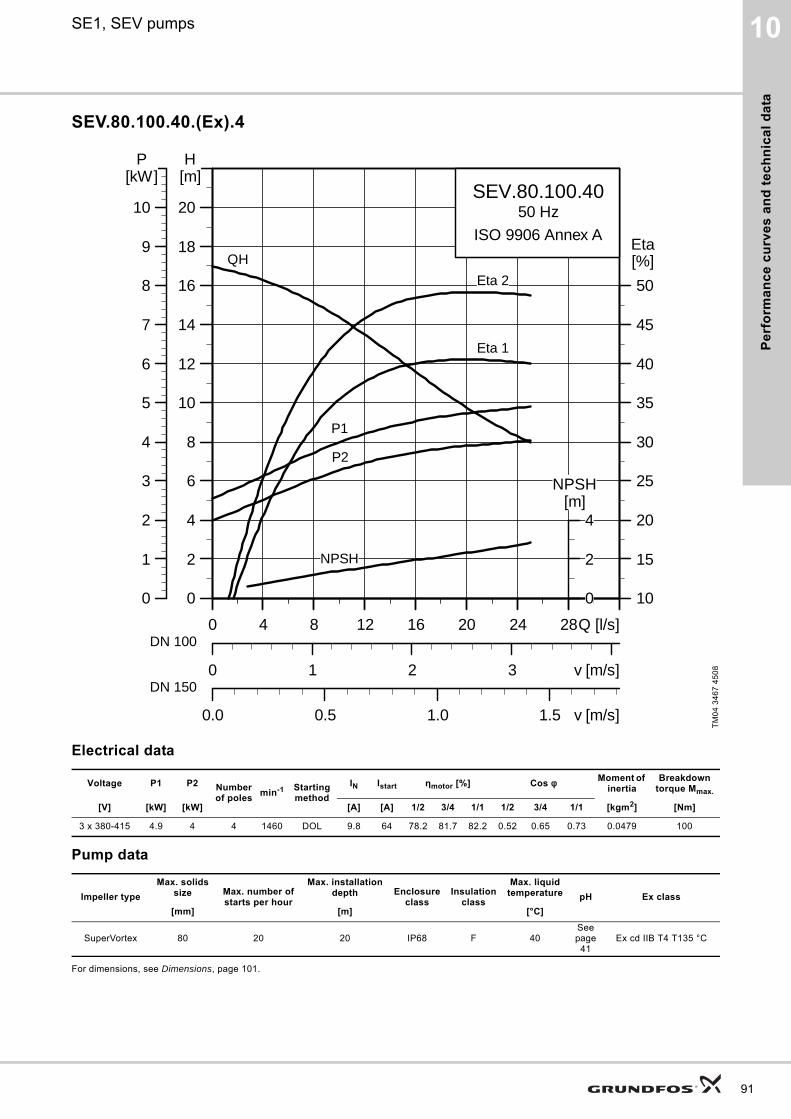
Pe
rfo
rma
nc
e c
urv
es
an
d t
ec
hn
ica
l d
ata
10SE1, SEV pumps
SEV.80.100.40.(Ex).4
Electrical data
Pump data
For dimensions, see Dimensions, page 101.
TM
04
34
67
45
08
Voltage P1 P2 Number of poles
min-1 Starting method
IN Istart ηmotor [%] Cos φ Moment of inertia
Breakdown torque Mmax.
[V] [kW] [kW] [A] [A] 1/2 3/4 1/1 1/2 3/4 1/1 [kgm2] [Nm]
3 x 380-415 4.9 4 4 1460 DOL 9.8 64 78.2 81.7 82.2 0.52 0.65 0.73 0.0479 100
Impeller type
Max. solids size Max. number of
starts per hour
Max. installation depth Enclosure
classInsulation
class
Max. liquid temperature pH Ex class
[mm] [m] [°C]
SuperVortex 80 20 20 IP68 F 40See page
41Ex cd IIB T4 T135 °C
0 4 8 12 16 20 24 28Q [l/s]
0
2
4
6
8
10
12
14
16
18
20
[m]H
0 1 2 3 v [m/s]
10
15
20
25
30
35
40
45
50
[%]Eta
0.0 0.5 1.0 1.5 v [m/s]
SEV.80.100.4050 Hz
ISO 9906 Annex A
QH
Eta 2
Eta 1
P2
P1
NPSH
0 4 8 12 16 20 24 28Q [l/s]
0
1
2
3
4
5
6
7
8
9
10
[kW]P
0
2
4[m]
NPSH
DN 100
DN 150
91
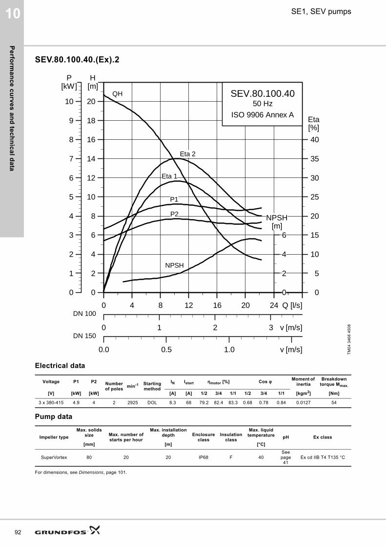
Pe
rform
an
ce
cu
rve
s a
nd
tec
hn
ica
l da
ta
92
10 SE1, SEV pumps
SEV.80.100.40.(Ex).2
Electrical data
Pump data
For dimensions, see Dimensions, page 101.
TM
04
34
68
45
08
Voltage P1 P2 Number of poles
min-1 Starting method
IN Istart ηmotor [%] Cos φ Moment of inertia
Breakdown torque Mmax.
[V] [kW] [kW] [A] [A] 1/2 3/4 1/1 1/2 3/4 1/1 [kgm2] [Nm]
3 x 380-415 4.9 4 2 2925 DOL 8.3 68 79.2 82.4 83.3 0.68 0.78 0.84 0.0127 54
Impeller type
Max. solids size Max. number of
starts per hour
Max. installation depth Enclosure
classInsulation
class
Max. liquid temperature pH Ex class
[mm] [m] [°C]
SuperVortex 80 20 20 IP68 F 40See page
41Ex cd IIB T4 T135 °C
0 4 8 12 16 20 24 Q [l/s]
0
2
4
6
8
10
12
14
16
18
20
[m]H
0 1 2 3 v [m/s]
0
5
10
15
20
25
30
35
40
[%]Eta
0.0 0.5 1.0 v [m/s]
SEV.80.100.4050 Hz
ISO 9906 Annex A
QH
Eta 2
Eta 1
P2
P1
NPSH
0 4 8 12 16 20 24 Q [l/s]
0
1
2
3
4
5
6
7
8
9
10
[kW]P
0
2
4
6[m]
NPSH
DN 100
DN 150
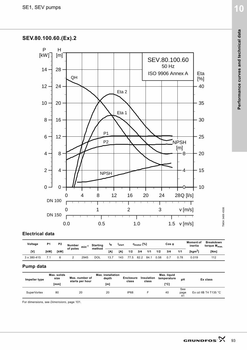
Pe
rfo
rma
nc
e c
urv
es
an
d t
ec
hn
ica
l d
ata
10SE1, SEV pumps
SEV.80.100.60.(Ex).2
Electrical data
Pump data
For dimensions, see Dimensions, page 101.
TM
04
34
69
45
08
Voltage P1 P2 Number of poles
min-1 Starting method
IN Istart ηmotor [%] Cos φ Moment of inertia
Breakdown torque Mmax.
[V] [kW] [kW] [A] [A] 1/2 3/4 1/1 1/2 3/4 1/1 [kgm2] [Nm]
3 x 380-415 7.1 6 2 2945 DOL 13.7 143 77.5 82.2 84.1 0.58 0.7 0.78 0.019 112
Impeller type
Max. solids size Max. number of
starts per hour
Max. installation depth Enclosure
classInsulation
class
Max. liquid temperature pH Ex class
[mm] [m] [°C]
SuperVortex 80 20 20 IP68 F 40See page
41Ex cd IIB T4 T135 °C
0 4 8 12 16 20 24 28Q [l/s]
0
4
8
12
16
20
24
28
[m]H
0 1 2 3 v [m/s]
10
15
20
25
30
35
40
[%]Eta
0.0 0.5 1.0 1.5 v [m/s]
SEV.80.100.6050 Hz
ISO 9906 Annex AQH
Eta 2
Eta 1
P2
P1
NPSH
0 4 8 12 16 20 24 28Q [l/s]
0
2
4
6
8
10
12
14
[kW]P
0
4
8[m]
NPSH
DN 100
DN 150
93
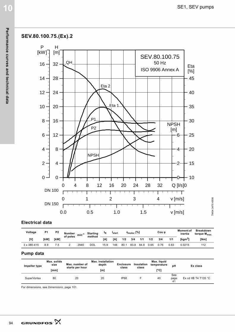
Pe
rform
an
ce
cu
rve
s a
nd
tec
hn
ica
l da
ta
94
10 SE1, SEV pumps
SEV.80.100.75.(Ex).2
Electrical data
Pump data
For dimensions, see Dimensions, page 101.
TM
04
34
70
45
08
Voltage P1 P2 Number of poles
min-1 Starting method
IN Istart ηmotor [%] Cos φ Moment of inertia
Breakdown torque Mmax.
[V] [kW] [kW] [A] [A] 1/2 3/4 1/1 1/2 3/4 1/1 [kgm2] [Nm]
3 x 380-415 8.9 7.5 2 2940 DOL 15.9 146 80.1 83.8 84.8 0.65 0.76 0.83 0.0215 112
Impeller type
Max. solids size Max. number of
starts per hour
Max. installation depth Enclosure
classInsulation
class
Max. liquid temperature pH Ex class
[mm] [m] [°C]
SuperVortex 80 20 20 IP68 F 40See page
41Ex cd IIB T4 T135 °C
0 4 8 12 16 20 24 28 32 40Q [l/s]
0
4
8
12
16
20
24
28
32
[m]H
0 1 2 3 4 v [m/s]
10
15
20
25
30
35
40
45
[%]Eta
0.0 0.5 1.0 1.5 v [m/s]
SEV.80.100.7550 Hz
ISO 9906 Annex A
QH
Eta 2
Eta 1
P2
P1
NPSH
0 4 8 12 16 20 24 28 32 Q [l/s]
0
2
4
6
8
10
12
14
16
[kW]P
0
2
4
6[m]
NPSH
DN 100
DN 150
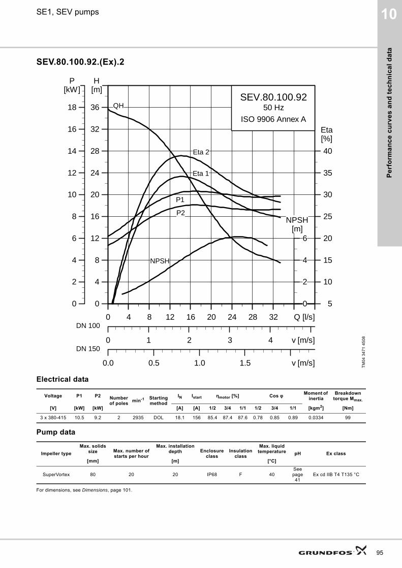
Pe
rfo
rma
nc
e c
urv
es
an
d t
ec
hn
ica
l d
ata
10SE1, SEV pumps
SEV.80.100.92.(Ex).2
Electrical data
Pump data
For dimensions, see Dimensions, page 101.
TM
04
34
71
45
08
Voltage P1 P2 Number of poles
min-1 Starting method
IN Istart ηmotor [%] Cos φ Moment of inertia
Breakdown torque Mmax.
[V] [kW] [kW] [A] [A] 1/2 3/4 1/1 1/2 3/4 1/1 [kgm2] [Nm]
3 x 380-415 10.5 9.2 2 2935 DOL 18.1 156 85.4 87.4 87.6 0.78 0.85 0.89 0.0334 99
Impeller type
Max. solids size Max. number of
starts per hour
Max. installation depth Enclosure
classInsulation
class
Max. liquid temperature pH Ex class
[mm] [m] [°C]
SuperVortex 80 20 20 IP68 F 40See page
41Ex cd IIB T4 T135 °C
0 4 8 12 16 20 24 28 32 Q [l/s]
0
4
8
12
16
20
24
28
32
36
[m]H
0 1 2 3 4 v [m/s]
5
10
15
20
25
30
35
40
[%]Eta
0.0 0.5 1.0 1.5 v [m/s]
SEV.80.100.9250 Hz
ISO 9906 Annex A
QH
Eta 2
Eta 1
P2
P1
NPSH
0 4 8 12 16 20 24 28 32 Q [l/s]
0
2
4
6
8
10
12
14
16
18
[kW]P
0
2
4
6[m]
NPSH
DN 100
DN 150
95
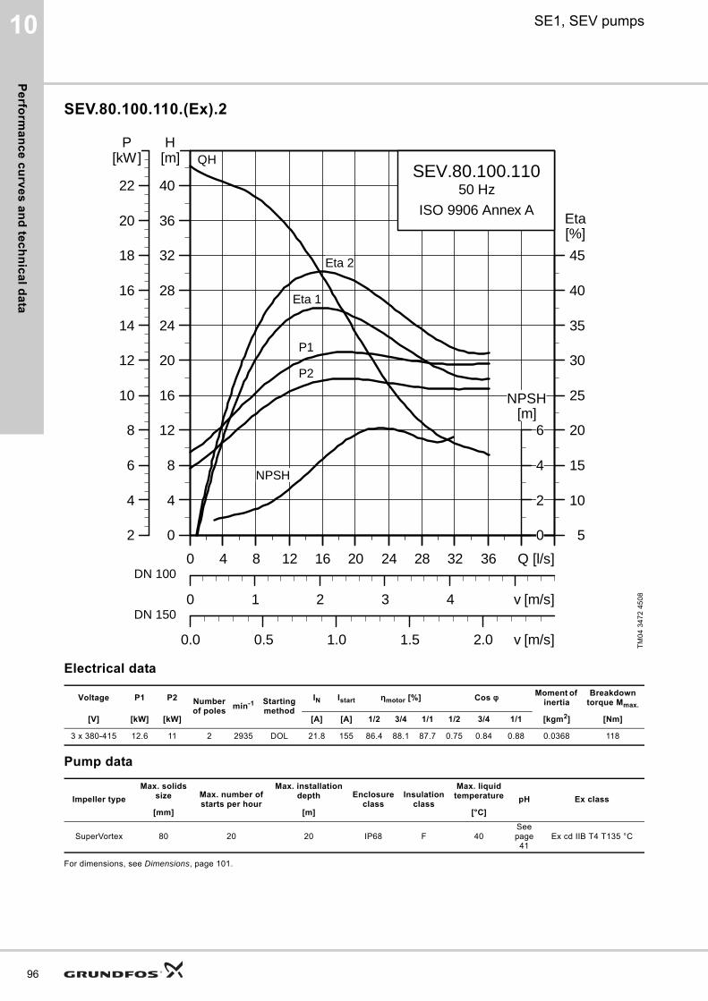
Pe
rform
an
ce
cu
rve
s a
nd
tec
hn
ica
l da
ta
96
10 SE1, SEV pumps
SEV.80.100.110.(Ex).2
Electrical data
Pump data
For dimensions, see Dimensions, page 101.
TM
04
34
72
45
08
Voltage P1 P2 Number of poles
min-1 Starting method
IN Istart ηmotor [%] Cos φ Moment of inertia
Breakdown torque Mmax.
[V] [kW] [kW] [A] [A] 1/2 3/4 1/1 1/2 3/4 1/1 [kgm2] [Nm]
3 x 380-415 12.6 11 2 2935 DOL 21.8 155 86.4 88.1 87.7 0.75 0.84 0.88 0.0368 118
Impeller type
Max. solids size Max. number of
starts per hour
Max. installation depth Enclosure
classInsulation
class
Max. liquid temperature pH Ex class
[mm] [m] [°C]
SuperVortex 80 20 20 IP68 F 40See page
41Ex cd IIB T4 T135 °C
0 4 8 12 16 20 24 28 32 36 Q [l/s]
0
4
8
12
16
20
24
28
32
36
40
[m]H
0 1 2 3 4 v [m/s]
5
10
15
20
25
30
35
40
45
[%]Eta
0.0 0.5 1.0 1.5 2.0 v [m/s]
SEV.80.100.11050 Hz
ISO 9906 Annex A
Eta 1
QH
Eta 2
P2
P1
NPSH
0 4 8 12 16 20 24 28 32 36 Q [l/s]
2
4
6
8
10
12
14
16
18
20
22
[kW]P
0
2
4
6[m]
NPSH
DN 100
DN 150
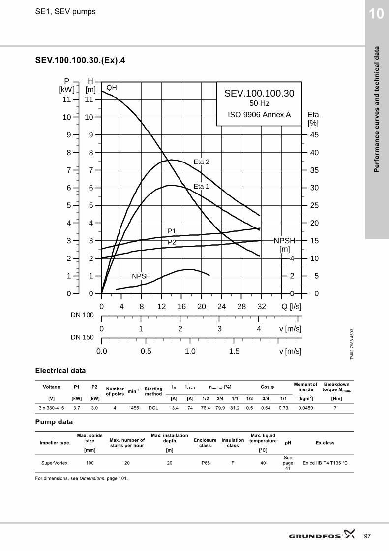
Pe
rfo
rma
nc
e c
urv
es
an
d t
ec
hn
ica
l d
ata
10SE1, SEV pumps
SEV.100.100.30.(Ex).4
Electrical data
Pump data
For dimensions, see Dimensions, page 101.
TM
02
79
88
45
03
Voltage P1 P2 Number of poles
min-1 Starting method
IN Istart ηmotor [%] Cos φ Moment of inertia
Breakdown torque Mmax.
[V] [kW] [kW] [A] [A] 1/2 3/4 1/1 1/2 3/4 1/1 [kgm2] [Nm]
3 x 380-415 3.7 3.0 4 1455 DOL 13.4 74 76.4 79.9 81.2 0.5 0.64 0.73 0.0450 71
Impeller type
Max. solids size Max. number of
starts per hour
Max. installation depth Enclosure
classInsulation
class
Max. liquid temperature pH Ex class
[mm] [m] [°C]
SuperVortex 100 20 20 IP68 F 40See page
41Ex cd IIB T4 T135 °C
0 4 8 12 16 20 24 28 32 Q [l/s]
0
1
2
3
4
5
6
7
8
9
10
11[m]H
0 1 2 3 4 v [m/s]
0
5
10
15
20
25
30
35
40
45
[%]Eta
0.0 0.5 1.0 1.5 v [m/s]
SEV.100.100.3050 Hz
ISO 9906 Annex A
Eta 2
Eta 1
QH
P2
P1
NPSH
0 4 8 12 16 20 24 28 32 Q [l/s]
0
1
2
3
4
5
6
7
8
9
10
11[kW]
P
0
2
4[m]
NPSH
DN 100
DN 150
97

Pe
rform
an
ce
cu
rve
s a
nd
tec
hn
ica
l da
ta
98
10 SE1, SEV pumps
SEV.100.100.40.(Ex).4
Electrical data
Pump data
For dimensions, see Dimensions, page 101.
TM
02
79
89
45
03
Voltage P1 P2 Number of poles
min-1 Starting method
IN Istart ηmotor [%] Cos φ Moment of inertia
Breakdown torque Mmax.
[V] [kW] [kW] [A] [A] 1/2 3/4 1/1 1/2 3/4 1/1 [kgm2] [Nm]
3 x 380-415 4.9 4.0 4 1460 Y/D 10 67 78.2 81.7 82.2 0.52 0.65 0.73 0.0501 100
Impeller type
Max. solids size Max. number of
starts per hour
Max. installation depth Enclosure
classInsulation
class
Max. liquid temperature pH Ex class
[mm] [m] [°C]
SuperVortex 100 20 20 IP68 F 40See page
41Ex cd IIB T4 T135 °C
0 4 8 12 16 20 24 28 32 Q [l/s]
0
1
2
3
4
5
6
7
8
9
10
11
12
13
14[m]H
0 1 2 3 4 v [m/s]
0
5
10
15
20
25
30
35
40
45
[%]Eta
0.0 0.5 1.0 1.5 v [m/s]
SEV.100.100.4050 Hz
ISO 9906 Annex A
Eta 2
Eta 1
QH
P2
P1
NPSH
0 4 8 12 16 20 24 28 32 Q [l/s]
0
1
2
3
4
5
6
7
8
9
10
11
12
13
14[kW]
P
0
2
4[m]
NPSH
DN 100
DN 150
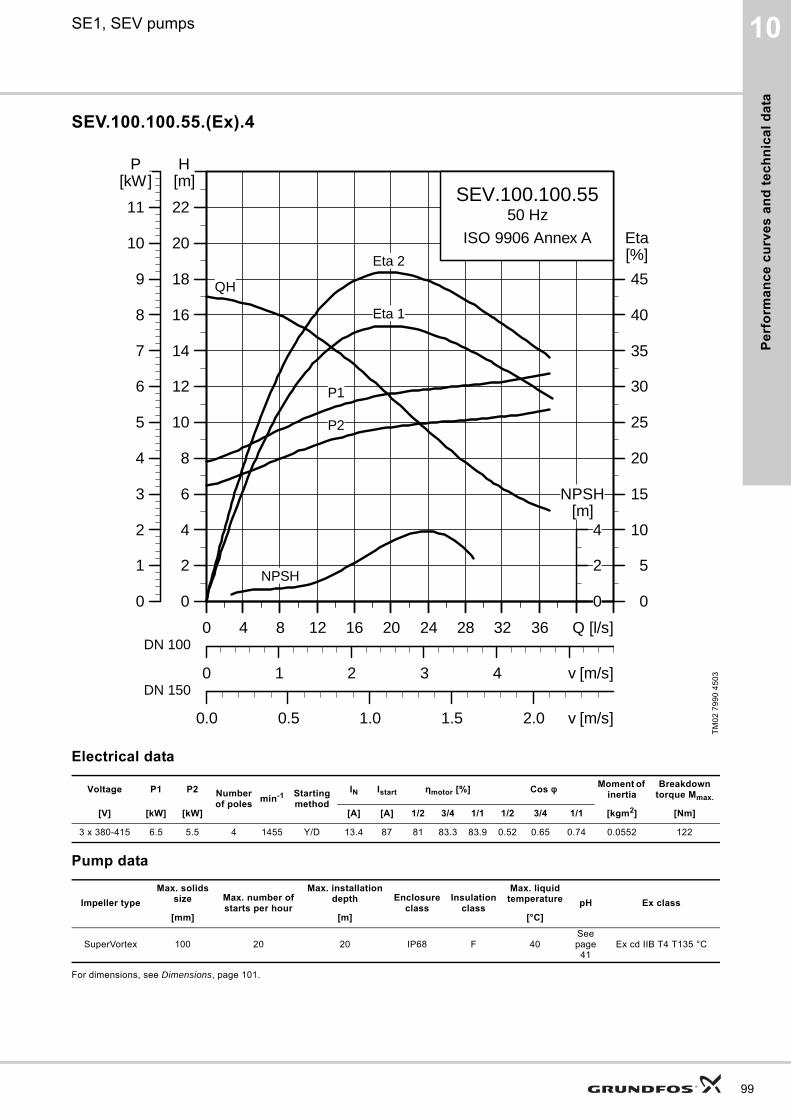
Pe
rfo
rma
nc
e c
urv
es
an
d t
ec
hn
ica
l d
ata
10SE1, SEV pumps
SEV.100.100.55.(Ex).4
Electrical data
Pump data
For dimensions, see Dimensions, page 101.
TM
02
79
90
45
03
Voltage P1 P2 Number of poles
min-1 Starting method
IN Istart ηmotor [%] Cos φ Moment of inertia
Breakdown torque Mmax.
[V] [kW] [kW] [A] [A] 1/2 3/4 1/1 1/2 3/4 1/1 [kgm2] [Nm]
3 x 380-415 6.5 5.5 4 1455 Y/D 13.4 87 81 83.3 83.9 0.52 0.65 0.74 0.0552 122
Impeller type
Max. solids size Max. number of
starts per hour
Max. installation depth Enclosure
classInsulation
class
Max. liquid temperature pH Ex class
[mm] [m] [°C]
SuperVortex 100 20 20 IP68 F 40See page
41Ex cd IIB T4 T135 °C
0 4 8 12 16 20 24 28 32 36 Q [l/s]
0
2
4
6
8
10
12
14
16
18
20
22
[m]H
0 1 2 3 4 v [m/s]
0
5
10
15
20
25
30
35
40
45
[%]Eta
0.0 0.5 1.0 1.5 2.0 v [m/s]
SEV.100.100.5550 Hz
ISO 9906 Annex AEta 2
Eta 1
QH
P2
P1
NPSH
0 4 8 12 16 20 24 28 32 36 Q [l/s]
0
1
2
3
4
5
6
7
8
9
10
11
[kW]P
0
2
4[m]
NPSH
DN 100
DN 150
99
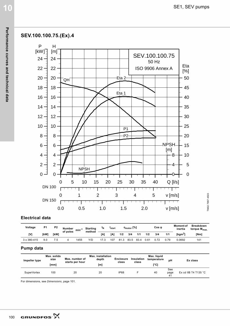
Pe
rform
an
ce
cu
rve
s a
nd
tec
hn
ica
l da
ta
100
10 SE1, SEV pumps
SEV.100.100.75.(Ex).4
Electrical data
Pump data
For dimensions, see Dimensions, page 101.
TM
02
79
97
45
03
Voltage P1 P2 Number of poles
min-1 Starting method
IN Istart ηmotor [%] Cos φ Moment of inertia
Breakdown torque Mmax.
[V] [kW] [kW] [A] [A] 1/2 3/4 1/1 1/2 3/4 1/1 [kgm2] [Nm]
3 x 380-415 9.0 7.5 4 1455 Y/D 17.3 107 81.3 83.5 83.4 0.61 0.72 0.79 0.0692 141
Impeller type
Max. solids size Max. number of
starts per hour
Max. installation depth Enclosure
classInsulation
class
Max. liquid temperature pH Ex class
[mm] [m] [°C]
SuperVortex 100 20 20 IP68 F 40See page
41Ex cd IIB T4 T135 °C
0 5 10 15 20 25 30 35 40 Q [l/s]
0
2
4
6
8
10
12
14
16
18
20
22
24
[m]H
0 1 2 3 4 5 v [m/s]
0
5
10
15
20
25
30
35
40
45
50
[%]Eta
0.0 0.5 1.0 1.5 2.0 v [m/s]
SEV.100.100.7550 Hz
ISO 9906 Annex A
Eta 2
Eta 1
QH
P2
P1
NPSH
0 5 10 15 20 25 30 35 40 Q [l/s]
0
2
4
6
8
10
12
14
16
18
20
22
24
[kW]P
0
4
8[m]
NPSH
DN 100
DN 150
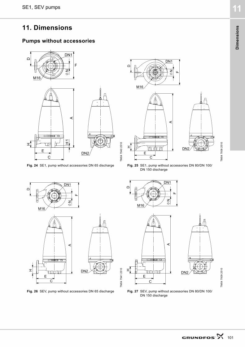
Dim
en
sio
ns
SE1, SEV pumps 11
11. Dimensions
Pumps without accessories
TM
04
79
40
25
10
TM
04
79
38
25
10
Fig. 24 SE1, pump without accessories DN 65 discharge Fig. 25 SE1, pump without accessories DN 80/DN 100/DN 150 discharge
TM
04
79
41
25
10
TM
04
79
39
25
10
Fig. 26 SEV, pump without accessories DN 65 discharge Fig. 27 SEV, pump without accessories DN 80/DN 100/DN 150 discharge
101
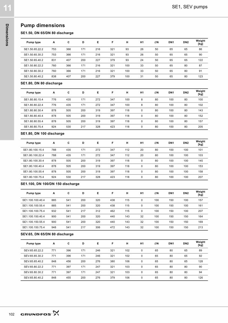
Dim
en
sio
ns
102
SE1, SEV pumps11
Pump dimensions
SE1.50, DN 65/DN 80 discharge
SE1.80, DN 80 discharge
SE1.80, DN 100 discharge
SE1.100, DN 100/DN 150 discharge
SEV.65, DN 65/DN 80 discharge
Pump type A C D E F H H1 ∅N DN1 DN2 Weight
[kg]
SE1.50.65.22.2 753 366 171 216 321 93 26 50 65 65 86
SE1.50.65.30.2 753 366 171 216 321 93 26 50 65 65 90
SE1.50.65.40.2 831 407 200 227 379 93 24 50 65 65 122
SE1.50.80.22.2 760 366 171 216 321 100 33 50 65 80 87
SE1.50.80.30.2 760 366 171 216 321 100 33 50 65 80 91
SE1.50.80.40.2 838 407 200 227 379 100 31 50 65 80 123
Pump type A C D E F H H1 ∅N DN1 DN2 Weight
[kg]
SE1.80.80.15.4 776 435 171 272 347 100 8 80 100 80 100
SE1.80.80.22.4 776 435 171 272 347 100 8 80 100 80 102
SE1.80.80.30.4 878 505 200 319 397 118 0 80 100 80 143
SE1.80.80.40.4 878 505 200 319 397 118 0 80 100 80 152
SE1.80.80.55.4 878 505 200 319 397 118 0 80 100 80 157
SE1.80.80.75.4 924 530 217 328 423 118 0 80 100 80 205
Pump type A C D E F H H1 ∅N DN1 DN2 Weight
[kg]
SE1.80.100.15.4 788 435 171 272 347 112 20 80 100 100 101
SE1.80.100.22.4 788 435 171 272 347 112 20 80 100 100 103
SE1.80.100.30.4 878 505 200 319 397 118 0 80 100 100 145
SE1.80.100.40.4 878 505 200 319 397 118 0 80 100 100 153
SE1.80.100.55.4 878 505 200 319 397 118 0 80 100 100 158
SE1.80.100.75.4 924 530 217 328 423 118 0 80 100 100 207
Pump type A C D E F H H1 ∅N DN1 DN2 Weight
[kg]
SE1.100.100.40.4 885 541 200 320 438 115 0 100 150 100 157
SE1.100.100.55.4 885 541 200 320 438 115 0 100 150 100 161
SE1.100.100.75.4 932 541 217 312 462 115 0 100 150 100 207
SE1.100.150.40.4 900 541 200 320 440 143 32 100 150 150 164
SE1.100.150.55.4 900 541 200 320 440 143 32 100 150 150 169
SE1.100.150.75.4 948 541 217 306 472 143 32 100 150 150 213
Pump type A C D E F H H1 ∅N DN1 DN2 Weight
[kg]
SEV.65.65.22.2 771 396 171 246 321 102 0 65 80 65 89
SEV.65.65.30.2 771 396 171 246 321 102 0 65 80 65 92
SEV.65.65.40.2 848 456 200 276 380 106 0 65 80 65 128
SEV.65.80.22.2 771 397 171 247 321 103 0 65 80 80 90
SEV.65.80.30.2 771 397 171 247 321 103 0 65 80 80 94
SEV.65.80.40.2 848 455 200 276 379 106 0 65 80 80 126
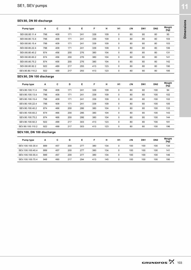
Dim
en
sio
ns
SE1, SEV pumps 11
SEV.80, DN 80 discharge
SEV.80, DN 100 discharge
SEV.100, DN 100 discharge
Pump type A C D E F H H1 ∅N DN1 DN2 Weight
[kg]
SEV.80.80.11.4 798 409 171 241 339 109 0 80 80 80 95
SEV.80.80.13.4 798 409 171 241 339 109 0 80 80 80 103
SEV.80.80.15.4 798 409 171 241 339 109 0 80 80 80 103
SEV.80.80.22.4 798 409 171 241 339 109 0 80 80 80 106
SEV.80.80.40.2 874 456 200 276 380 104 0 80 80 80 131
SEV.80.80.60.2 874 456 200 276 380 104 0 80 80 80 141
SEV.80.80.75.2 874 456 200 276 380 104 0 80 80 80 142
SEV.80.80.92.2 922 489 217 293 413 123 0 80 80 80 190
SEV.80.80.110.2 922 489 217 293 413 123 0 80 80 80 195
Pump type A C D E F H H1 ∅N DN1 DN2 Weight
[kg]
SEV.80.100.11.4 798 409 171 241 339 109 0 80 80 100 94
SEV.80.100.13.4 798 409 171 241 339 109 0 80 80 100 102
SEV.80.100.15.4 798 409 171 241 339 109 0 80 80 100 102
SEV.80.100.22.4 798 409 171 241 339 109 0 80 80 100 105
SEV.80.100.40.2 874 466 200 286 380 104 0 80 80 100 133
SEV.80.100.60.2 874 466 200 286 380 104 0 80 80 100 143
SEV.80.100.75.2 874 466 200 286 380 104 0 80 80 100 144
SEV.80.100.92.2 922 499 217 303 413 123 0 80 80 100 191
SEV.80.100.110.2 922 499 217 303 413 123 0 80 80 100 196
Pump type A C D E F H H1 ∅N DN1 DN2 Weight
[kg]
SEV.100.100.30.4 889 457 200 277 380 134 0 100 100 100 134
SEV.100.100.40.4 889 457 200 277 380 134 0 100 100 100 141
SEV.100.100.55.4 889 457 200 277 380 134 0 100 100 100 146
SEV.100.100.75.4 948 490 217 294 413 145 0 100 100 100 190
103
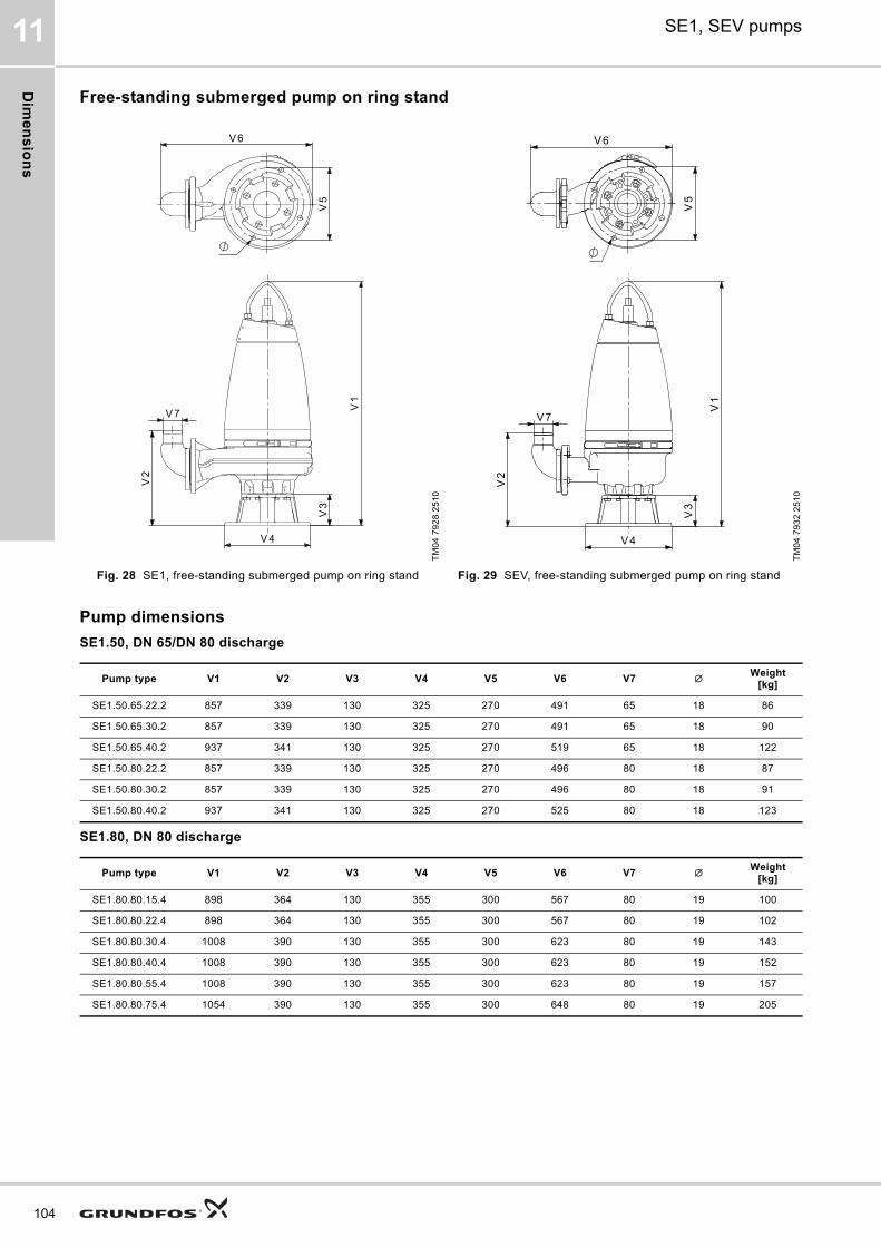
Dim
en
sio
ns
104
SE1, SEV pumps11
Free-standing submerged pump on ring stand
Pump dimensions
SE1.50, DN 65/DN 80 discharge
SE1.80, DN 80 discharge
TM
04
79
28
25
10
TM
04
79
32
25
10
Fig. 28 SE1, free-standing submerged pump on ring stand Fig. 29 SEV, free-standing submerged pump on ring stand
Pump type V1 V2 V3 V4 V5 V6 V7 ∅ Weight[kg]
SE1.50.65.22.2 857 339 130 325 270 491 65 18 86
SE1.50.65.30.2 857 339 130 325 270 491 65 18 90
SE1.50.65.40.2 937 341 130 325 270 519 65 18 122
SE1.50.80.22.2 857 339 130 325 270 496 80 18 87
SE1.50.80.30.2 857 339 130 325 270 496 80 18 91
SE1.50.80.40.2 937 341 130 325 270 525 80 18 123
Pump type V1 V2 V3 V4 V5 V6 V7 ∅ Weight[kg]
SE1.80.80.15.4 898 364 130 355 300 567 80 19 100
SE1.80.80.22.4 898 364 130 355 300 567 80 19 102
SE1.80.80.30.4 1008 390 130 355 300 623 80 19 143
SE1.80.80.40.4 1008 390 130 355 300 623 80 19 152
SE1.80.80.55.4 1008 390 130 355 300 623 80 19 157
SE1.80.80.75.4 1054 390 130 355 300 648 80 19 205

Dim
en
sio
ns
SE1, SEV pumps 11
SE1.80, DN 100 discharge
SE1.100, DN 100/DN 150 discharge
SEV.65, DN 65/DN 80 discharge
SEV.80, DN 80 discharge
Pump type V1 V2 V3 V4 V5 V6 V7 ∅ Weight[kg]
SE1.80.100.15.4 898 369 130 355 300 591 100 19 101
SE1.80.100.22.4 898 369 130 355 300 591 100 19 103
SE1.80.100.30.4 1008 395 130 355 300 647 100 19 145
SE1.80.100.40.4 1008 395 130 355 300 647 100 19 153
SE1.80.100.55.4 1008 395 130 355 300 647 100 19 158
SE1.80.100.75.4 1054 395 130 355 300 672 100 19 207
Pump type V1 V2 V3 V4 V5 V6 V7 ∅ Weight[kg]
SE1.100.100.40.4 1071 445 186 450 400 711 100 22 157
SE1.100.100.55.4 1071 445 186 450 400 711 100 22 161
SE1.100.100.75.4 1118 445 186 450 400 706 100 22 207
SE1.100.150.40.4 1054 555 186 450 400 807 150 22 164
SE1.100.150.55.4 1054 555 186 450 400 807 150 22 169
SE1.100.150.75.4 1102 555 186 450 400 803 150 22 213
Pump type V1 V2 V3 V4 V5 V6 V7 ∅ Weight[kg]
SEV.65.65.22.2 899 372 128 330 280 524 65 18 89
SEV.65.65.30.2 899 372 128 330 280 524 65 18 92
SEV.65.65.40.2 976 376 128 330 280 568 65 18 128
SEV.65.80.22.2 899 373 128 330 280 530 80 18 90
SEV.65.80.30.2 899 373 128 330 280 530 80 18 94
SEV.65.80.40.2 976 376 128 330 280 573 80 18 126
Pump type V1 V2 V3 V4 V5 V6 V7 ∅ Weight[kg]
SEV.80.80.11.4 926 379 128 330 280 527 80 18 95
SEV.80.80.13.4 926 379 128 330 280 527 80 18 103
SEV.80.80.15.4 926 379 128 330 280 527 80 18 103
SEV.80.80.22.4 926 379 128 330 280 527 80 18 106
SEV.80.80.40.2 1002 374 128 330 280 574 80 18 131
SEV.80.80.60.2 1002 374 128 330 280 574 80 18 141
SEV.80.80.75.2 1002 374 128 330 280 574 80 18 142
SEV.80.80.92.2 1050 393 128 330 280 607 80 18 190
105
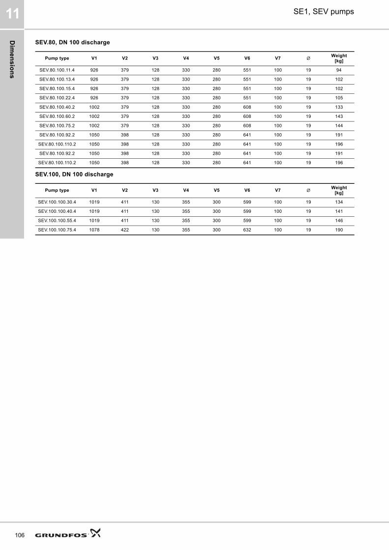
Dim
en
sio
ns
106
SE1, SEV pumps11
SEV.80, DN 100 discharge
SEV.100, DN 100 discharge
Pump type V1 V2 V3 V4 V5 V6 V7 ∅ Weight[kg]
SEV.80.100.11.4 926 379 128 330 280 551 100 19 94
SEV.80.100.13.4 926 379 128 330 280 551 100 19 102
SEV.80.100.15.4 926 379 128 330 280 551 100 19 102
SEV.80.100.22.4 926 379 128 330 280 551 100 19 105
SEV.80.100.40.2 1002 379 128 330 280 608 100 19 133
SEV.80.100.60.2 1002 379 128 330 280 608 100 19 143
SEV.80.100.75.2 1002 379 128 330 280 608 100 19 144
SEV.80.100.92.2 1050 398 128 330 280 641 100 19 191
SEV.80.100.110.2 1050 398 128 330 280 641 100 19 196
SEV.80.100.92.2 1050 398 128 330 280 641 100 19 191
SEV.80.100.110.2 1050 398 128 330 280 641 100 19 196
Pump type V1 V2 V3 V4 V5 V6 V7 ∅ Weight[kg]
SEV.100.100.30.4 1019 411 130 355 300 599 100 19 134
SEV.100.100.40.4 1019 411 130 355 300 599 100 19 141
SEV.100.100.55.4 1019 411 130 355 300 599 100 19 146
SEV.100.100.75.4 1078 422 130 355 300 632 100 19 190
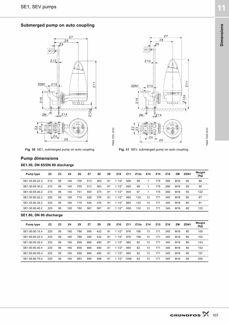
Dim
en
sio
ns
SE1, SEV pumps 11
Submerged pump on auto coupling
Pump dimensions
SE1.50, DN 65/DN 80 discharge
SE1.80, DN 80 discharge
TM
04
79
31
25
10
TM
04
79
35
25
10
Fig. 30 SE1, submerged pump on auto coupling Fig. 31 SEV, submerged pump on auto coupling
Pump type Z2 Z3 Z4 Z6 Z7 Z8 Z9 Z10 Z11 Z12a Z14 Z15 Z16 ZM ZDN1Weight
[kg]
SE1.50.65.22.2 210 95 140 700 513 363 81 1 1/2" 826 99 1 175 266 M16 65 86
SE1.50.65.30.2 210 95 140 700 513 363 81 1 1/2" 826 99 1 175 266 M16 65 90
SE1.50.65.40.2 210 95 140 741 554 375 81 1 1/2" 904 97 1 175 266 M16 65 122
SE1.50.80.22.2 220 95 160 719 526 376 81 1 1/2" 860 133 13 171 345 M16 80 87
SE1.50.80.30.2 220 95 160 719 526 376 81 1 1/2" 860 133 13 171 345 M16 80 91
SE1.50.80.40.2 220 95 160 760 567 387 81 1 1/2" 938 132 13 171 345 M16 80 123
Pump type Z2 Z3 Z4 Z6 Z7 Z8 Z9 Z10 Z11 Z12a Z14 Z15 Z16 ZM ZDN1Weight
[kg]
SE1.80.80.15.4 220 95 160 788 595 432 81 1 1/2" 876 108 13 171 345 M16 80 100
SE1.80.80.22.4 220 95 160 788 595 432 81 1 1/2" 876 108 13 171 345 M16 80 102
SE1.80.80.30.4 220 95 160 858 666 480 81 1 1/2" 960 82 13 171 345 M16 80 143
SE1.80.80.40.4 220 95 160 858 666 480 81 1 1/2" 960 82 13 171 345 M16 80 152
SE1.80.80.55.4 220 95 160 858 666 480 81 1 1/2" 960 82 13 171 345 M16 80 157
SE1.80.80.75.4 220 95 160 883 690 489 81 1 1/2" 1006 82 13 171 345 M16 80 205
107
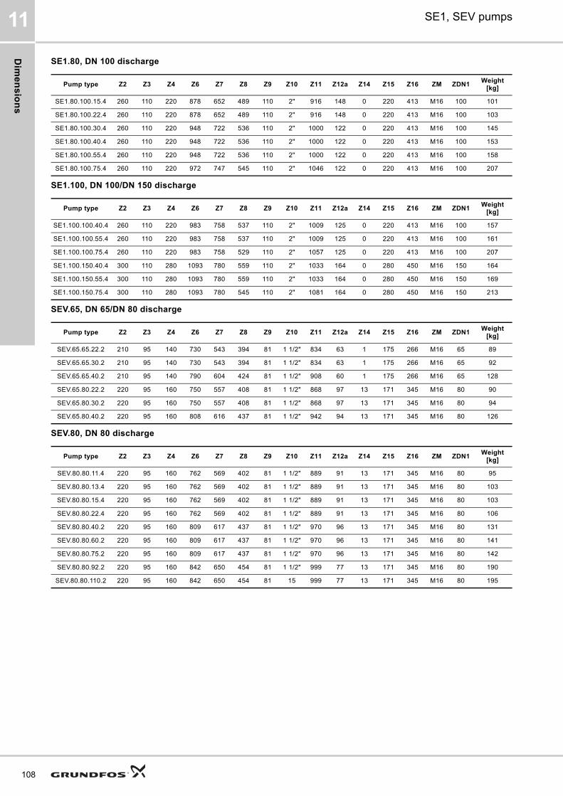
Dim
en
sio
ns
108
SE1, SEV pumps11
SE1.80, DN 100 discharge
SE1.100, DN 100/DN 150 discharge
SEV.65, DN 65/DN 80 discharge
SEV.80, DN 80 discharge
Pump type Z2 Z3 Z4 Z6 Z7 Z8 Z9 Z10 Z11 Z12a Z14 Z15 Z16 ZM ZDN1Weight
[kg]
SE1.80.100.15.4 260 110 220 878 652 489 110 2" 916 148 0 220 413 M16 100 101
SE1.80.100.22.4 260 110 220 878 652 489 110 2" 916 148 0 220 413 M16 100 103
SE1.80.100.30.4 260 110 220 948 722 536 110 2" 1000 122 0 220 413 M16 100 145
SE1.80.100.40.4 260 110 220 948 722 536 110 2" 1000 122 0 220 413 M16 100 153
SE1.80.100.55.4 260 110 220 948 722 536 110 2" 1000 122 0 220 413 M16 100 158
SE1.80.100.75.4 260 110 220 972 747 545 110 2" 1046 122 0 220 413 M16 100 207
Pump type Z2 Z3 Z4 Z6 Z7 Z8 Z9 Z10 Z11 Z12a Z14 Z15 Z16 ZM ZDN1Weight
[kg]
SE1.100.100.40.4 260 110 220 983 758 537 110 2" 1009 125 0 220 413 M16 100 157
SE1.100.100.55.4 260 110 220 983 758 537 110 2" 1009 125 0 220 413 M16 100 161
SE1.100.100.75.4 260 110 220 983 758 529 110 2" 1057 125 0 220 413 M16 100 207
SE1.100.150.40.4 300 110 280 1093 780 559 110 2" 1033 164 0 280 450 M16 150 164
SE1.100.150.55.4 300 110 280 1093 780 559 110 2" 1033 164 0 280 450 M16 150 169
SE1.100.150.75.4 300 110 280 1093 780 545 110 2" 1081 164 0 280 450 M16 150 213
Pump type Z2 Z3 Z4 Z6 Z7 Z8 Z9 Z10 Z11 Z12a Z14 Z15 Z16 ZM ZDN1Weight
[kg]
SEV.65.65.22.2 210 95 140 730 543 394 81 1 1/2" 834 63 1 175 266 M16 65 89
SEV.65.65.30.2 210 95 140 730 543 394 81 1 1/2" 834 63 1 175 266 M16 65 92
SEV.65.65.40.2 210 95 140 790 604 424 81 1 1/2" 908 60 1 175 266 M16 65 128
SEV.65.80.22.2 220 95 160 750 557 408 81 1 1/2" 868 97 13 171 345 M16 80 90
SEV.65.80.30.2 220 95 160 750 557 408 81 1 1/2" 868 97 13 171 345 M16 80 94
SEV.65.80.40.2 220 95 160 808 616 437 81 1 1/2" 942 94 13 171 345 M16 80 126
Pump type Z2 Z3 Z4 Z6 Z7 Z8 Z9 Z10 Z11 Z12a Z14 Z15 Z16 ZM ZDN1Weight
[kg]
SEV.80.80.11.4 220 95 160 762 569 402 81 1 1/2" 889 91 13 171 345 M16 80 95
SEV.80.80.13.4 220 95 160 762 569 402 81 1 1/2" 889 91 13 171 345 M16 80 103
SEV.80.80.15.4 220 95 160 762 569 402 81 1 1/2" 889 91 13 171 345 M16 80 103
SEV.80.80.22.4 220 95 160 762 569 402 81 1 1/2" 889 91 13 171 345 M16 80 106
SEV.80.80.40.2 220 95 160 809 617 437 81 1 1/2" 970 96 13 171 345 M16 80 131
SEV.80.80.60.2 220 95 160 809 617 437 81 1 1/2" 970 96 13 171 345 M16 80 141
SEV.80.80.75.2 220 95 160 809 617 437 81 1 1/2" 970 96 13 171 345 M16 80 142
SEV.80.80.92.2 220 95 160 842 650 454 81 1 1/2" 999 77 13 171 345 M16 80 190
SEV.80.80.110.2 220 95 160 842 650 454 81 15 999 77 13 171 345 M16 80 195
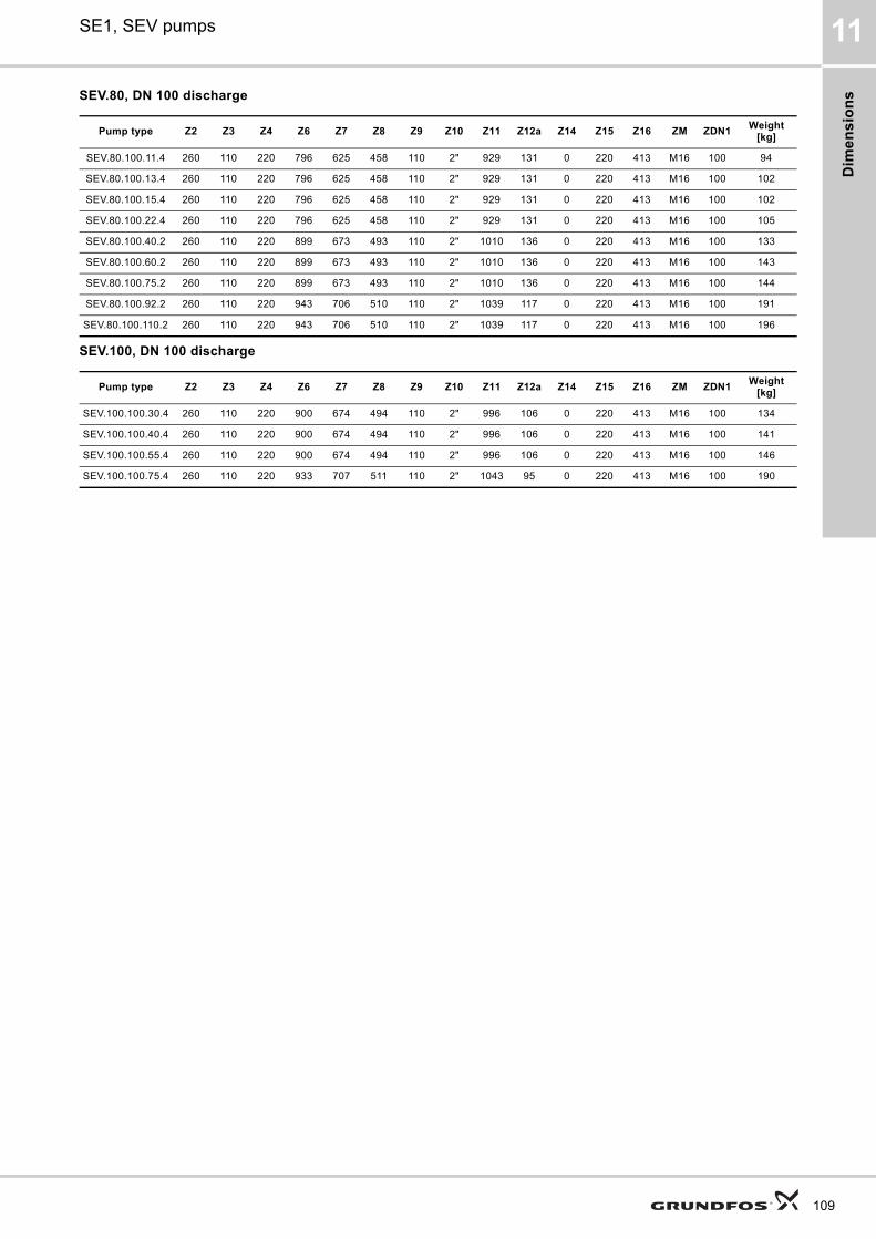
Dim
en
sio
ns
SE1, SEV pumps 11
SEV.80, DN 100 discharge
SEV.100, DN 100 discharge
Pump type Z2 Z3 Z4 Z6 Z7 Z8 Z9 Z10 Z11 Z12a Z14 Z15 Z16 ZM ZDN1Weight
[kg]
SEV.80.100.11.4 260 110 220 796 625 458 110 2" 929 131 0 220 413 M16 100 94
SEV.80.100.13.4 260 110 220 796 625 458 110 2" 929 131 0 220 413 M16 100 102
SEV.80.100.15.4 260 110 220 796 625 458 110 2" 929 131 0 220 413 M16 100 102
SEV.80.100.22.4 260 110 220 796 625 458 110 2" 929 131 0 220 413 M16 100 105
SEV.80.100.40.2 260 110 220 899 673 493 110 2" 1010 136 0 220 413 M16 100 133
SEV.80.100.60.2 260 110 220 899 673 493 110 2" 1010 136 0 220 413 M16 100 143
SEV.80.100.75.2 260 110 220 899 673 493 110 2" 1010 136 0 220 413 M16 100 144
SEV.80.100.92.2 260 110 220 943 706 510 110 2" 1039 117 0 220 413 M16 100 191
SEV.80.100.110.2 260 110 220 943 706 510 110 2" 1039 117 0 220 413 M16 100 196
Pump type Z2 Z3 Z4 Z6 Z7 Z8 Z9 Z10 Z11 Z12a Z14 Z15 Z16 ZM ZDN1Weight
[kg]
SEV.100.100.30.4 260 110 220 900 674 494 110 2" 996 106 0 220 413 M16 100 134
SEV.100.100.40.4 260 110 220 900 674 494 110 2" 996 106 0 220 413 M16 100 141
SEV.100.100.55.4 260 110 220 900 674 494 110 2" 996 106 0 220 413 M16 100 146
SEV.100.100.75.4 260 110 220 933 707 511 110 2" 1043 95 0 220 413 M16 100 190
109
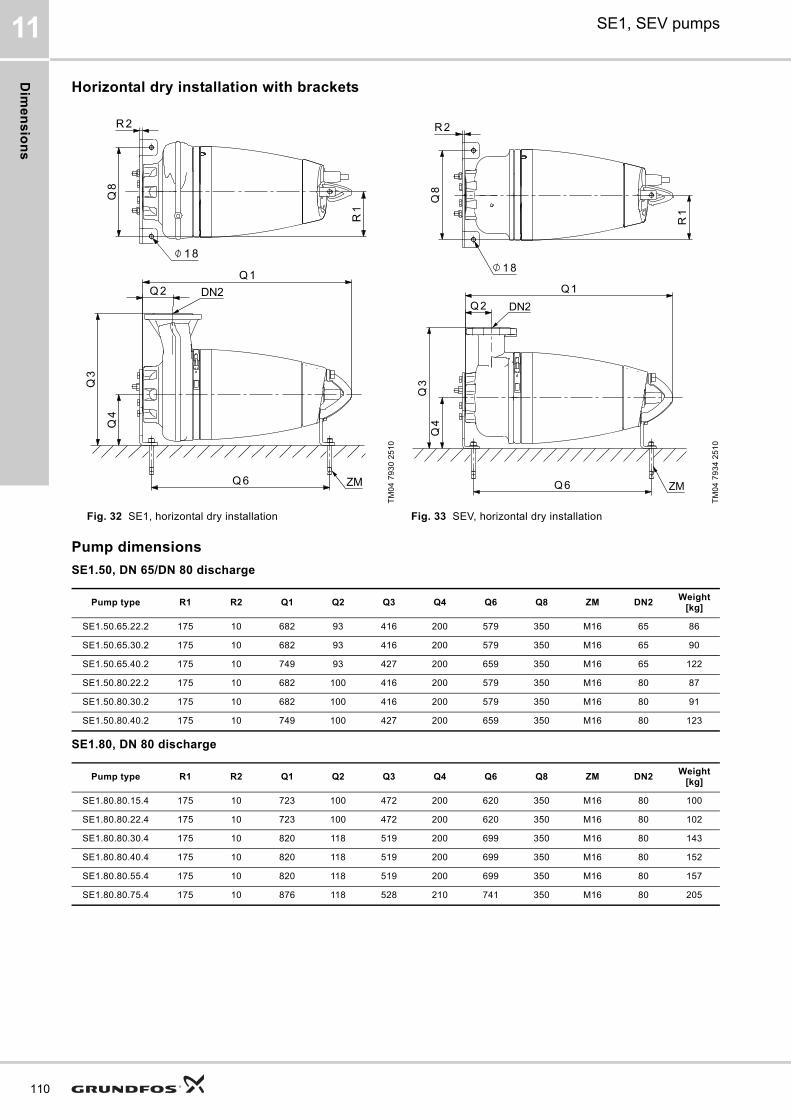
Dim
en
sio
ns
110
SE1, SEV pumps11
Horizontal dry installation with brackets
Pump dimensions
SE1.50, DN 65/DN 80 discharge
SE1.80, DN 80 discharge
TM
04
79
30
25
10
TM
04
79
34
25
10
Fig. 32 SE1, horizontal dry installation Fig. 33 SEV, horizontal dry installation
Pump type R1 R2 Q1 Q2 Q3 Q4 Q6 Q8 ZM DN2Weight
[kg]
SE1.50.65.22.2 175 10 682 93 416 200 579 350 M16 65 86
SE1.50.65.30.2 175 10 682 93 416 200 579 350 M16 65 90
SE1.50.65.40.2 175 10 749 93 427 200 659 350 M16 65 122
SE1.50.80.22.2 175 10 682 100 416 200 579 350 M16 80 87
SE1.50.80.30.2 175 10 682 100 416 200 579 350 M16 80 91
SE1.50.80.40.2 175 10 749 100 427 200 659 350 M16 80 123
Pump type R1 R2 Q1 Q2 Q3 Q4 Q6 Q8 ZM DN2Weight
[kg]
SE1.80.80.15.4 175 10 723 100 472 200 620 350 M16 80 100
SE1.80.80.22.4 175 10 723 100 472 200 620 350 M16 80 102
SE1.80.80.30.4 175 10 820 118 519 200 699 350 M16 80 143
SE1.80.80.40.4 175 10 820 118 519 200 699 350 M16 80 152
SE1.80.80.55.4 175 10 820 118 519 200 699 350 M16 80 157
SE1.80.80.75.4 175 10 876 118 528 210 741 350 M16 80 205
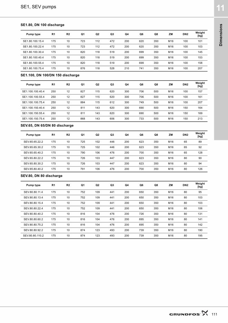
Dim
en
sio
ns
SE1, SEV pumps 11
SE1.80, DN 100 discharge
SE1.100, DN 100/DN 150 discharge
SEV.65, DN 65/DN 80 discharge
SEV.80, DN 80 discharge
Pump type R1 R2 Q1 Q2 Q3 Q4 Q6 Q8 ZM DN2Weight
[kg]
SE1.80.100.15.4 175 10 723 112 472 200 620 350 M16 100 101
SE1.80.100.22.4 175 10 723 112 472 200 620 350 M16 100 103
SE1.80.100.30.4 175 10 820 118 519 200 699 350 M16 100 145
SE1.80.100.40.4 175 10 820 118 519 200 699 350 M16 100 153
SE1.80.100.55.4 175 10 820 118 519 200 699 350 M16 100 158
SE1.80.100.75.4 175 10 876 118 528 210 741 350 M16 100 207
Pump type R1 R2 Q1 Q2 Q3 Q4 Q6 Q8 ZM DN2Weight
[kg]
SE1.100.100.40.4 250 12 827 115 620 300 706 500 M16 100 157
SE1.100.100.55.4 250 12 827 115 620 300 706 500 M16 100 161
SE1.100.100.75.4 250 12 884 115 612 300 749 500 M16 100 207
SE1.100.150.40.4 250 12 811 143 620 300 690 500 M16 150 164
SE1.100.150.55.4 250 12 811 143 620 300 690 500 M16 150 169
SE1.100.150.75.4 250 12 868 143 606 300 733 500 M16 150 213
Pump type R1 R2 Q1 Q2 Q3 Q4 Q6 Q8 ZM DN2Weight
[kg]
SEV.65.65.22.2 175 10 725 102 446 200 623 350 M16 65 89
SEV.65.65.30.2 175 10 725 102 446 200 623 350 M16 65 92
SEV.65.65.40.2 175 10 790 106 476 200 700 350 M16 65 128
SEV.65.80.22.2 175 10 726 103 447 200 623 350 M16 80 90
SEV.65.80.30.2 175 10 726 103 447 200 623 350 M16 80 94
SEV.65.80.40.2 175 10 791 106 476 200 700 350 M16 80 126
Pump type R1 R2 Q1 Q2 Q3 Q4 Q6 Q8 ZM DN2Weight
[kg]
SEV.80.80.11.4 175 10 752 109 441 200 650 350 M16 80 95
SEV.80.80.13.4 175 10 752 109 441 200 650 350 M16 80 103
SEV.80.80.15.4 175 10 752 109 441 200 650 350 M16 80 103
SEV.80.80.22.4 175 10 752 109 441 200 650 350 M16 80 106
SEV.80.80.40.2 175 10 816 104 476 200 726 350 M16 80 131
SEV.80.80.60.2 175 10 816 104 476 200 695 350 M16 80 141
SEV.80.80.75.2 175 10 816 104 476 200 695 350 M16 80 142
SEV.80.80.92.2 175 10 874 123 493 200 739 350 M16 80 190
SEV.80.80.110.2 175 10 874 123 493 200 739 350 M16 80 195
111
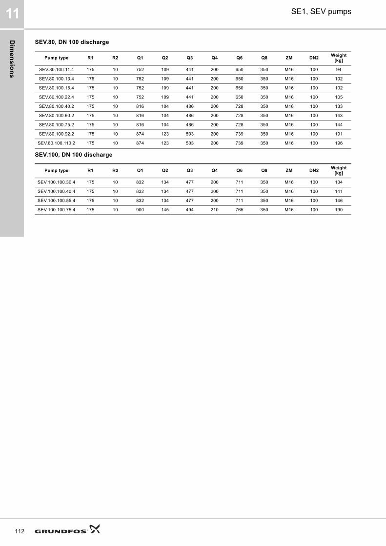
Dim
en
sio
ns
112
SE1, SEV pumps11
SEV.80, DN 100 discharge
SEV.100, DN 100 discharge
Pump type R1 R2 Q1 Q2 Q3 Q4 Q6 Q8 ZM DN2Weight
[kg]
SEV.80.100.11.4 175 10 752 109 441 200 650 350 M16 100 94
SEV.80.100.13.4 175 10 752 109 441 200 650 350 M16 100 102
SEV.80.100.15.4 175 10 752 109 441 200 650 350 M16 100 102
SEV.80.100.22.4 175 10 752 109 441 200 650 350 M16 100 105
SEV.80.100.40.2 175 10 816 104 486 200 728 350 M16 100 133
SEV.80.100.60.2 175 10 816 104 486 200 728 350 M16 100 143
SEV.80.100.75.2 175 10 816 104 486 200 728 350 M16 100 144
SEV.80.100.92.2 175 10 874 123 503 200 739 350 M16 100 191
SEV.80.100.110.2 175 10 874 123 503 200 739 350 M16 100 196
Pump type R1 R2 Q1 Q2 Q3 Q4 Q6 Q8 ZM DN2Weight
[kg]
SEV.100.100.30.4 175 10 832 134 477 200 711 350 M16 100 134
SEV.100.100.40.4 175 10 832 134 477 200 711 350 M16 100 141
SEV.100.100.55.4 175 10 832 134 477 200 711 350 M16 100 146
SEV.100.100.75.4 175 10 900 145 494 210 765 350 M16 100 190
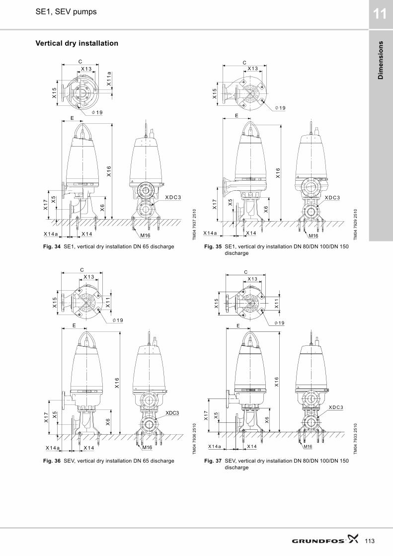
Dim
en
sio
ns
SE1, SEV pumps 11
Vertical dry installation
TM
04
79
37
25
10
TM
04
79
29
25
10
Fig. 34 SE1, vertical dry installation DN 65 discharge Fig. 35 SE1, vertical dry installation DN 80/DN 100/DN 150 discharge
TM
04
79
36
25
10
TM
04
79
33
25
10
Fig. 36 SEV, vertical dry installation DN 65 discharge Fig. 37 SEV, vertical dry installation DN 80/DN 100/DN 150 discharge
113
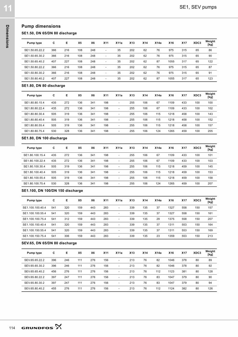
Dim
en
sio
ns
114
SE1, SEV pumps11
Pump dimensions
SE1.50, DN 65/DN 80 discharge
SE1.80, DN 80 discharge
SE1.80, DN 100 discharge
SE1.100, DN 100/DN 150 discharge
SEV.65, DN 65/DN 80 discharge
Pump type C E X5 X6 X11 X11a X13 X14 X14a X16 X17 XDC3Weight
[kg]
SE1.50.65.22.2 366 216 108 248 - 35 202 62 76 975 315 65 86
SE1.50.65.30.2 366 216 108 248 - 35 202 62 76 975 315 65 90
SE1.50.65.40.2 407 227 108 248 - 35 202 62 87 1055 317 65 122
SE1.50.80.22.2 366 216 108 248 - 35 202 62 76 975 315 65 87
SE1.50.80.30.2 366 216 108 248 - 35 202 62 76 975 315 65 91
SE1.50.80.40.2 407 227 108 248 - 35 202 62 87 1055 317 65 123
Pump type C E X5 X6 X11 X11a X13 X14 X14a X16 X17 XDC3Weight
[kg]
SE1.80.80.15.4 435 272 136 341 198 - 255 106 67 1109 433 100 100
SE1.80.80.22.4 435 272 136 341 198 - 255 106 67 1109 433 100 102
SE1.80.80.30.4 505 319 136 341 198 - 255 106 115 1218 458 100 143
SE1.80.80.40.4 505 319 136 341 198 - 255 106 115 1218 458 100 152
SE1.80.80.55.4 505 319 136 341 198 - 255 106 115 1218 458 100 157
SE1.80.80.75.4 530 328 136 341 198 - 255 106 124 1265 459 100 205
Pump type C E X5 X6 X11 X11a X13 X14 X14a X16 X17 XDC3Weight
[kg]
SE1.80.100.15.4 435 272 136 341 198 - 255 106 67 1109 433 100 101
SE1.80.100.22.4 435 272 136 341 198 - 255 106 67 1109 433 100 103
SE1.80.100.30.4 505 319 136 341 198 - 255 106 115 1218 459 100 145
SE1.80.100.40.4 505 319 136 341 198 - 255 106 115 1218 459 100 153
SE1.80.100.55.4 505 319 136 341 198 - 255 106 115 1218 459 100 158
SE1.80.100.75.4 530 328 136 341 198 - 255 106 124 1265 459 100 207
Pump type C E X5 X6 X11 X11a X13 X14 X14a X16 X17 XDC3Weight
[kg]
SE1.100.100.40.4 541 320 159 443 283 - 339 135 37 1327 558 150 157
SE1.100.100.55.4 541 320 159 443 283 - 339 135 37 1327 558 150 161
SE1.100.100.75.4 541 312 159 443 283 - 339 135 29 1375 558 150 207
SE1.100.150.40.4 541 320 159 443 283 - 339 135 37 1311 553 150 164
SE1.100.150.55.4 541 320 159 443 283 - 339 135 37 1311 553 150 169
SE1.100.150.75.4 541 306 159 443 283 - 339 135 23 1359 553 150 213
Pump type C E X5 X6 X11 X11a X13 X14 X14a X16 X17 XDC3Weight
[kg]
SEV.65.65.22.2 396 246 111 276 156 - 213 76 82 1046 378 80 89
SEV.65.65.30.2 396 246 111 276 156 - 213 76 82 1046 378 80 92
SEV.65.65.40.2 456 276 111 276 156 - 213 76 112 1123 381 80 128
SEV.65.80.22.2 397 247 111 276 156 - 213 76 83 1047 379 80 90
SEV.65.80.30.2 397 247 111 276 156 - 213 76 83 1047 379 80 94
SEV.65.80.40.2 455 276 111 276 156 - 213 76 112 1124 382 80 126
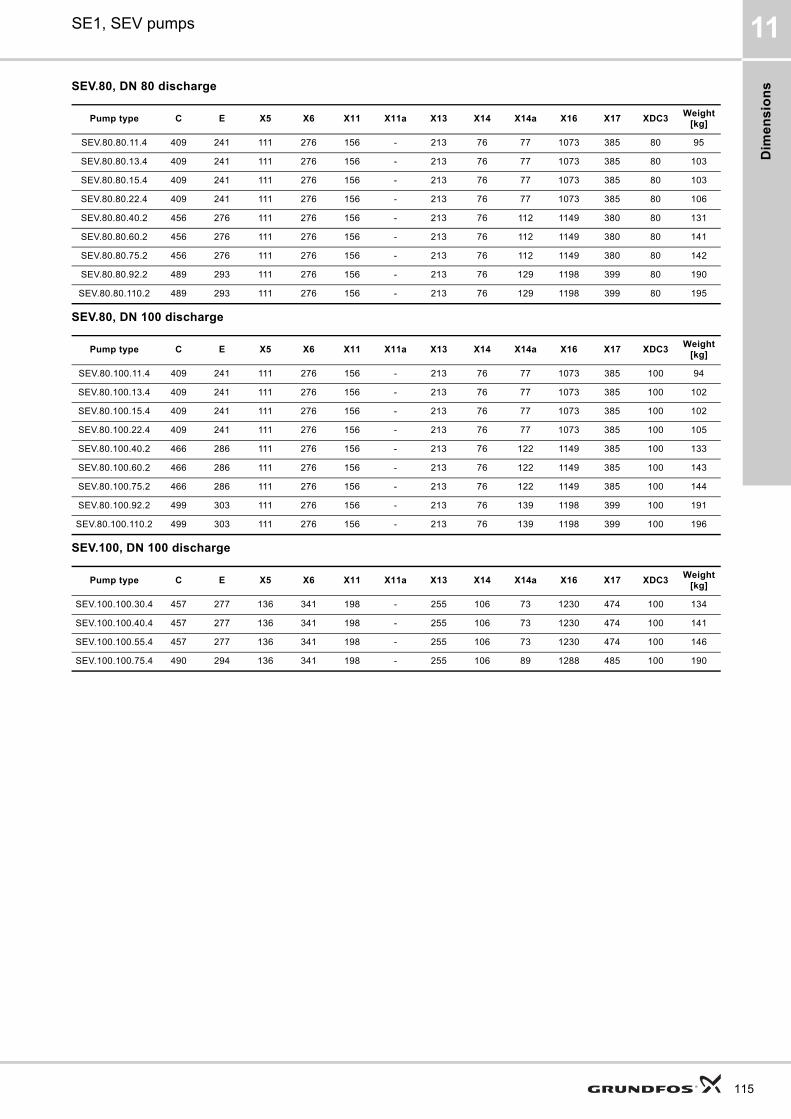
Dim
en
sio
ns
SE1, SEV pumps 11
SEV.80, DN 80 discharge
SEV.80, DN 100 discharge
SEV.100, DN 100 discharge
Pump type C E X5 X6 X11 X11a X13 X14 X14a X16 X17 XDC3Weight
[kg]
SEV.80.80.11.4 409 241 111 276 156 - 213 76 77 1073 385 80 95
SEV.80.80.13.4 409 241 111 276 156 - 213 76 77 1073 385 80 103
SEV.80.80.15.4 409 241 111 276 156 - 213 76 77 1073 385 80 103
SEV.80.80.22.4 409 241 111 276 156 - 213 76 77 1073 385 80 106
SEV.80.80.40.2 456 276 111 276 156 - 213 76 112 1149 380 80 131
SEV.80.80.60.2 456 276 111 276 156 - 213 76 112 1149 380 80 141
SEV.80.80.75.2 456 276 111 276 156 - 213 76 112 1149 380 80 142
SEV.80.80.92.2 489 293 111 276 156 - 213 76 129 1198 399 80 190
SEV.80.80.110.2 489 293 111 276 156 - 213 76 129 1198 399 80 195
Pump type C E X5 X6 X11 X11a X13 X14 X14a X16 X17 XDC3Weight
[kg]
SEV.80.100.11.4 409 241 111 276 156 - 213 76 77 1073 385 100 94
SEV.80.100.13.4 409 241 111 276 156 - 213 76 77 1073 385 100 102
SEV.80.100.15.4 409 241 111 276 156 - 213 76 77 1073 385 100 102
SEV.80.100.22.4 409 241 111 276 156 - 213 76 77 1073 385 100 105
SEV.80.100.40.2 466 286 111 276 156 - 213 76 122 1149 385 100 133
SEV.80.100.60.2 466 286 111 276 156 - 213 76 122 1149 385 100 143
SEV.80.100.75.2 466 286 111 276 156 - 213 76 122 1149 385 100 144
SEV.80.100.92.2 499 303 111 276 156 - 213 76 139 1198 399 100 191
SEV.80.100.110.2 499 303 111 276 156 - 213 76 139 1198 399 100 196
Pump type C E X5 X6 X11 X11a X13 X14 X14a X16 X17 XDC3Weight
[kg]
SEV.100.100.30.4 457 277 136 341 198 - 255 106 73 1230 474 100 134
SEV.100.100.40.4 457 277 136 341 198 - 255 106 73 1230 474 100 141
SEV.100.100.55.4 457 277 136 341 198 - 255 106 73 1230 474 100 146
SEV.100.100.75.4 490 294 136 341 198 - 255 106 89 1288 485 100 190
115
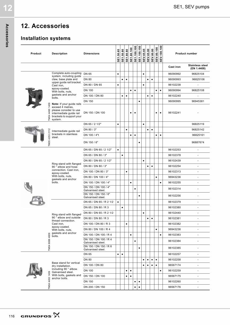
Ac
ce
ss
orie
s
116
SE1, SEV pumps12
12. Accessories
Installation systems
Product Description Dimensions
SE
1.5
0.6
5
SE
1.5
0.8
0
SE
1.8
0.8
0
SE
1.8
0.1
00
SE
1.1
00
.10
0
SE
1.1
00
.15
0
SE
V.6
5.6
5
SE
V.6
5.8
0
SE
V.8
0.8
0
SE
V.8
0.1
00
SE
V.1
00
.10
0
Product number
Cast ironStainless steel
(EN 1.4408)
TM
04
44
90
14
09
Complete auto-coupling system, including guide claw, base plate and upper guide rail bracket. Cast iron, epoxy-coated.With bolts, nuts, gaskets and anchor bolts.
Note: If your guide rails exceed 4 metres, please consider to use intermediate guide rail brackets to support your system.
DN 65 ● ● 96090992 96825104
DN 80 ● ● ● ● 96090993 96825106
DN 80 / DN 65 ● ● 96102238 -
DN 100 ● ● ● ● 96090994 96825108
DN 100 / DN 80 ● ● ● ● 96102240 -
DN 150 ● 96090995 96945381
DN 150 / DN 100 ● ● ● ● 96102241 -
TM
05
42
53
211
2
Intermediate guide rail brackets in stainless steel.
DN 65 / 2 1/2" ● ● 96825119
DN 80 / 3" ● ● ● 96825142
DN 100 / 4"t ● ● ● ● 96825161
DN 150 / 6" ● 96887674
TM
04
60
86
48
09
Ring stand with flanged 90 ° elbow and hose connection. Cast iron, epoxy-coated. With bolts, nuts, gaskets and anchor bolts.
DN 65 / DN 65 / 2 1/2" ● 96102253 -
DN 65 / DN 80 / 3" ● 96102378 -
DN 80 / DN 65 / 2 1/2" ● 96102439 -
DN 80 / DN 80 / 3" ● ● 96102254 -
DN 100 / DN 80 / 3" ● 96102313 -
DN 80 / DN 100 / 4" ● 96943236 -
DN 100 / DN 100 / 4" ● ● 96102255 -
DN 150 / DN 100 / 4"Galvanised steel.
● 96102314 -
DN 150 / DN 150 / 6"Galvanised steel.
● 96102256 -
Ring stand with flanged 90 ° elbow and outside thread connection. Cast iron, epoxy-coated. With bolts, nuts, gaskets and anchor bolts.
DN 65 / DN 65 / R 2 1/2 ● 96102379 -
DN 65 / DN 80 / R 3 ● 96102380 -
DN 80 / DN 65 / R 2 1/2 ● 96102440 -
DN 80 / DN 80 / R 3 ● ● 96102381 -
DN 100 / DN 80 / R 3 ● 96102382 -
DN 80 / DN 100 / R 4 ● 96943236 -
DN 100 / DN 100 / R 4 ● ● 96102383 -
DN 150 / DN 100 / R 4Galvanised steel.
● 96102384 -
DN 150 / DN 150 / R 6Galvanised steel.
● 96102385 -
TM
04
44
93
14
09
Base stand for vertical dry installation, including 90 ° elbow. Galvanised steel. With bolts, gaskets and anchor bolts.
DN 65 ● ● 96102257 -
DN 80 ● ● ● ● 96102258 -
DN 100 / DN 80 ● ● ● ● 96567174 -
DN 100 ● ● ● 96102259 -
DN 150 / DN 100 ● ● 96567175 -
DN 150 ● ● 96102260 -
DN 200 / DN 150 ● ● 96567176 -
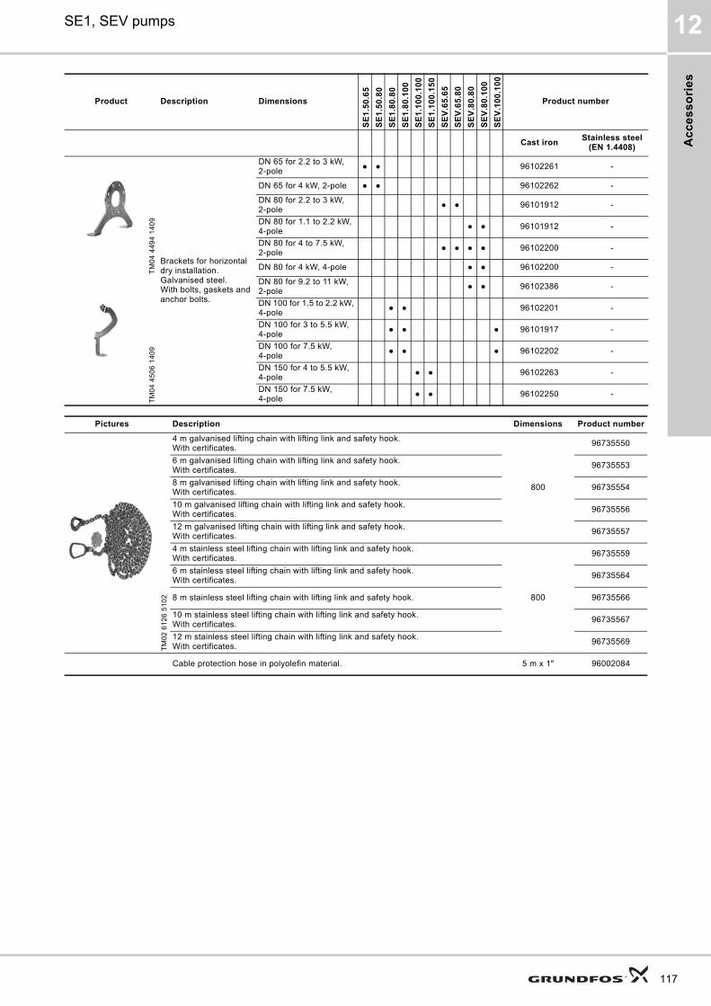
Ac
ce
ss
ori
es
SE1, SEV pumps 12
TM
04
44
94
14
09
Brackets for horizontal dry installation. Galvanised steel.With bolts, gaskets and anchor bolts.
DN 65 for 2.2 to 3 kW, 2-pole
● ● 96102261 -
DN 65 for 4 kW, 2-pole ● ● 96102262 -
DN 80 for 2.2 to 3 kW, 2-pole
● ● 96101912 -
DN 80 for 1.1 to 2.2 kW, 4-pole
● ● 96101912 -
DN 80 for 4 to 7.5 kW, 2-pole
● ● ● ● 96102200 -
DN 80 for 4 kW, 4-pole ● ● 96102200 -
TM
04
45
06
14
09
DN 80 for 9.2 to 11 kW, 2-pole
● ● 96102386 -
DN 100 for 1.5 to 2.2 kW, 4-pole
● ● 96102201 -
DN 100 for 3 to 5.5 kW, 4-pole
● ● ● 96101917 -
DN 100 for 7.5 kW, 4-pole
● ● ● 96102202 -
DN 150 for 4 to 5.5 kW, 4-pole
● ● 96102263 -
DN 150 for 7.5 kW, 4-pole
● ● 96102250 -
Product Description Dimensions
SE
1.5
0.6
5
SE
1.5
0.8
0
SE
1.8
0.8
0
SE
1.8
0.1
00
SE
1.1
00
.10
0
SE
1.1
00
.15
0
SE
V.6
5.6
5
SE
V.6
5.8
0
SE
V.8
0.8
0
SE
V.8
0.1
00
SE
V.1
00
.10
0
Product number
Cast ironStainless steel
(EN 1.4408)
Pictures Description Dimensions Product number
TM
02
61
26
51
02
4 m galvanised lifting chain with lifting link and safety hook. With certificates.
800
96735550
6 m galvanised lifting chain with lifting link and safety hook. With certificates.
96735553
8 m galvanised lifting chain with lifting link and safety hook.With certificates.
96735554
10 m galvanised lifting chain with lifting link and safety hook. With certificates.
96735556
12 m galvanised lifting chain with lifting link and safety hook. With certificates.
96735557
4 m stainless steel lifting chain with lifting link and safety hook.With certificates.
800
96735559
6 m stainless steel lifting chain with lifting link and safety hook.With certificates.
96735564
8 m stainless steel lifting chain with lifting link and safety hook. 96735566
10 m stainless steel lifting chain with lifting link and safety hook.With certificates.
96735567
12 m stainless steel lifting chain with lifting link and safety hook.With certificates.
96735569
Cable protection hose in polyolefin material. 5 m x 1" 96002084
117
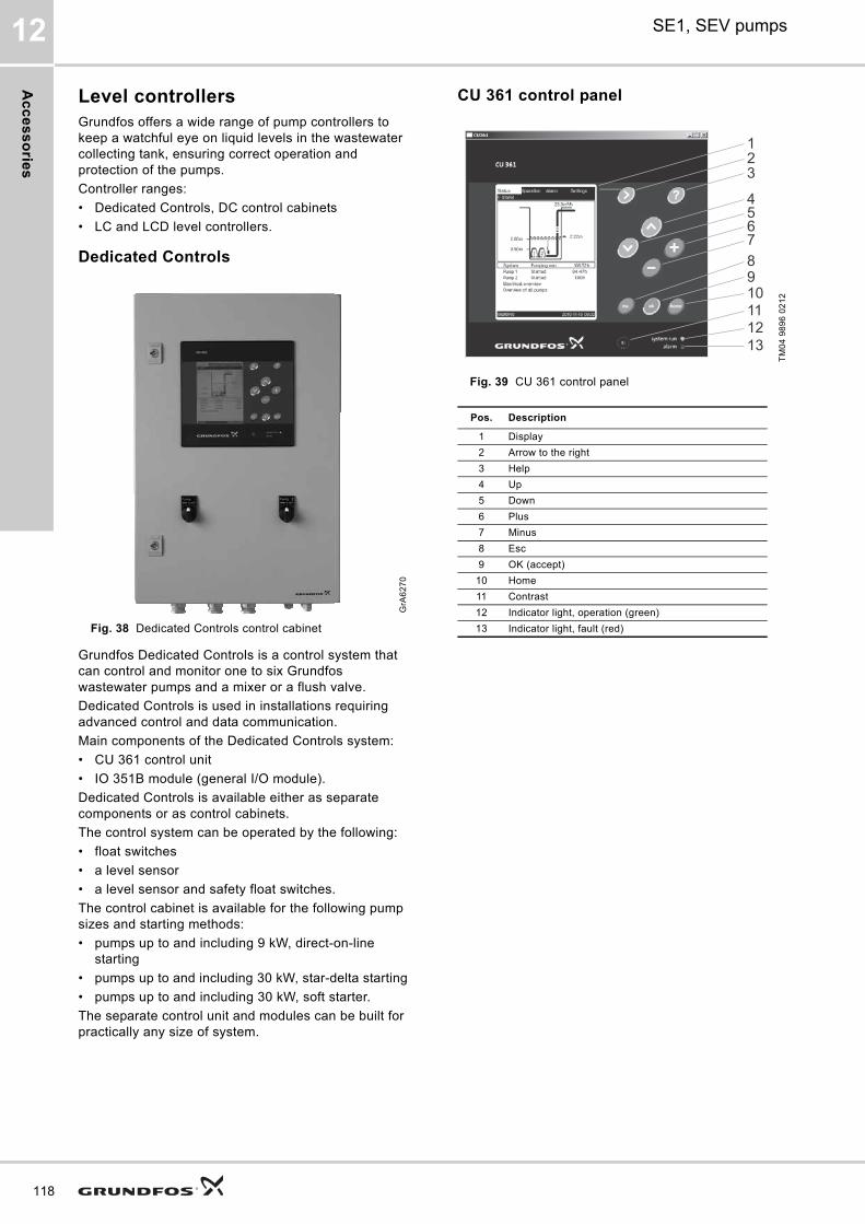
Ac
ce
ss
orie
s
118
SE1, SEV pumps12
Level controllersGrundfos offers a wide range of pump controllers to keep a watchful eye on liquid levels in the wastewater collecting tank, ensuring correct operation and protection of the pumps.
Controller ranges:
• Dedicated Controls, DC control cabinets
• LC and LCD level controllers.
Dedicated Controls
Fig. 38 Dedicated Controls control cabinet
Grundfos Dedicated Controls is a control system that can control and monitor one to six Grundfos wastewater pumps and a mixer or a flush valve.
Dedicated Controls is used in installations requiring advanced control and data communication.
Main components of the Dedicated Controls system:
• CU 361 control unit
• IO 351B module (general I/O module).
Dedicated Controls is available either as separate components or as control cabinets.
The control system can be operated by the following:
• float switches
• a level sensor
• a level sensor and safety float switches.
The control cabinet is available for the following pump sizes and starting methods:
• pumps up to and including 9 kW, direct-on-line starting
• pumps up to and including 30 kW, star-delta starting
• pumps up to and including 30 kW, soft starter.
The separate control unit and modules can be built for practically any size of system.
CU 361 control panel
Fig. 39 CU 361 control panel
GrA
62
70
TM
04
98
96
02
12
Pos. Description
1 Display
2 Arrow to the right
3 Help
4 Up
5 Down
6 Plus
7 Minus
8 Esc
9 OK (accept)
10 Home
11 Contrast
12 Indicator light, operation (green)
13 Indicator light, fault (red)
21
3
45678910111213
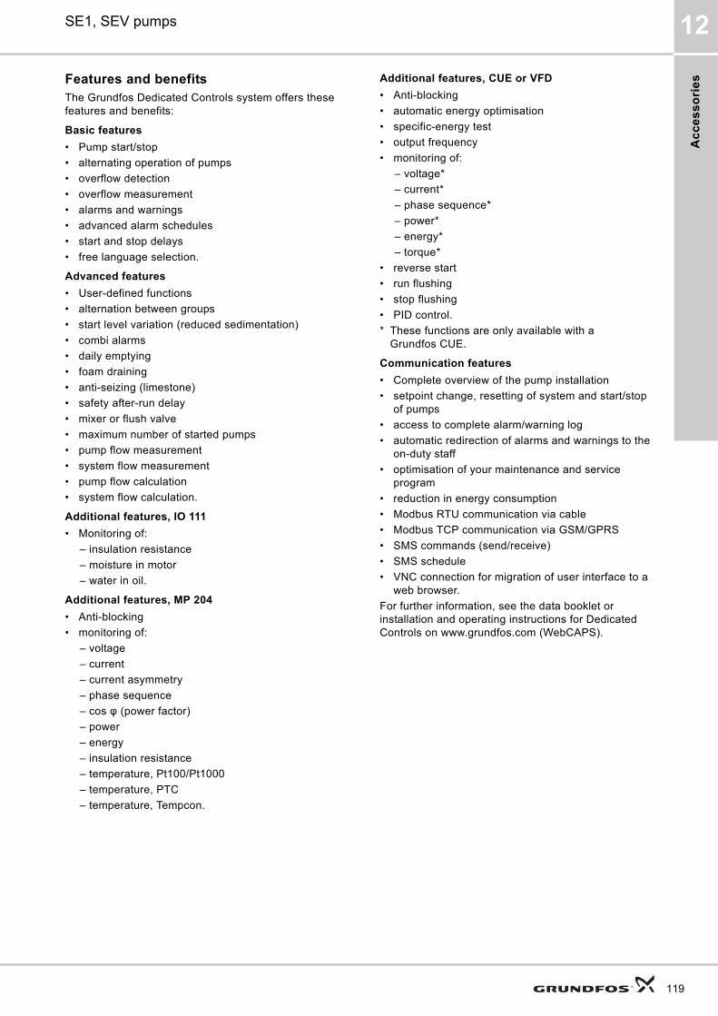
Ac
ce
ss
ori
es
SE1, SEV pumps 12
Features and benefitsThe Grundfos Dedicated Controls system offers these features and benefits:
Basic features
• Pump start/stop
• alternating operation of pumps
• overflow detection
• overflow measurement
• alarms and warnings
• advanced alarm schedules
• start and stop delays
• free language selection.
Advanced features
• User-defined functions
• alternation between groups
• start level variation (reduced sedimentation)
• combi alarms
• daily emptying
• foam draining
• anti-seizing (limestone)
• safety after-run delay
• mixer or flush valve
• maximum number of started pumps
• pump flow measurement
• system flow measurement
• pump flow calculation
• system flow calculation.
Additional features, IO 111
• Monitoring of:
– insulation resistance
– moisture in motor
– water in oil.
Additional features, MP 204
• Anti-blocking
• monitoring of:
– voltage
– current
– current asymmetry
– phase sequence
– cos φ (power factor)
– power
– energy
– insulation resistance
– temperature, Pt100/Pt1000
– temperature, PTC
– temperature, Tempcon.
Additional features, CUE or VFD
• Anti-blocking
• automatic energy optimisation
• specific-energy test
• output frequency
• monitoring of:
– voltage*
– current*
– phase sequence*
– power*
– energy*
– torque*
• reverse start
• run flushing
• stop flushing
• PID control.
* These functions are only available with a Grundfos CUE.
Communication features
• Complete overview of the pump installation
• setpoint change, resetting of system and start/stop of pumps
• access to complete alarm/warning log
• automatic redirection of alarms and warnings to the on-duty staff
• optimisation of your maintenance and service program
• reduction in energy consumption
• Modbus RTU communication via cable
• Modbus TCP communication via GSM/GPRS
• SMS commands (send/receive)
• SMS schedule
• VNC connection for migration of user interface to a web browser.
For further information, see the data booklet or installation and operating instructions for Dedicated Controls on www.grundfos.com (WebCAPS).
119
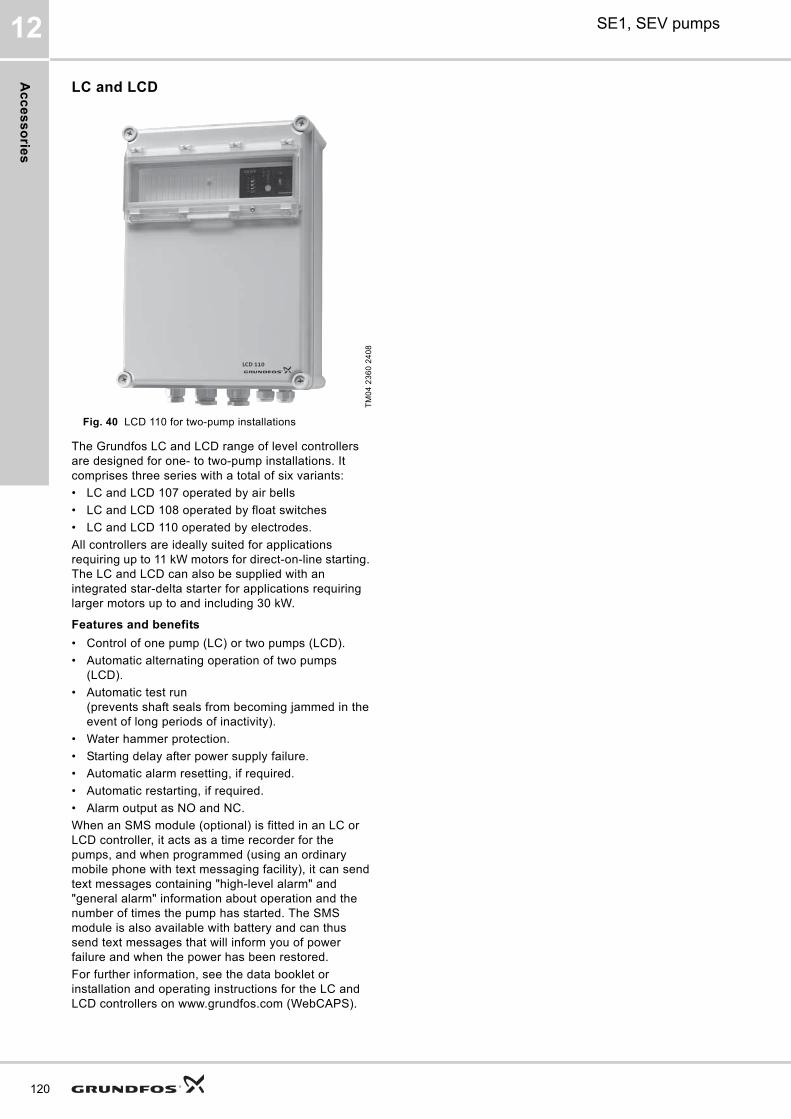
Ac
ce
ss
orie
s
120
SE1, SEV pumps12
LC and LCD
Fig. 40 LCD 110 for two-pump installations
The Grundfos LC and LCD range of level controllers are designed for one- to two-pump installations. It comprises three series with a total of six variants:
• LC and LCD 107 operated by air bells
• LC and LCD 108 operated by float switches
• LC and LCD 110 operated by electrodes.
All controllers are ideally suited for applications requiring up to 11 kW motors for direct-on-line starting. The LC and LCD can also be supplied with an integrated star-delta starter for applications requiring larger motors up to and including 30 kW.
Features and benefits
• Control of one pump (LC) or two pumps (LCD).
• Automatic alternating operation of two pumps (LCD).
• Automatic test run(prevents shaft seals from becoming jammed in the event of long periods of inactivity).
• Water hammer protection.
• Starting delay after power supply failure.
• Automatic alarm resetting, if required.
• Automatic restarting, if required.
• Alarm output as NO and NC.
When an SMS module (optional) is fitted in an LC or LCD controller, it acts as a time recorder for the pumps, and when programmed (using an ordinary mobile phone with text messaging facility), it can send text messages containing "high-level alarm" and "general alarm" information about operation and the number of times the pump has started. The SMS module is also available with battery and can thus send text messages that will inform you of power failure and when the power has been restored.
For further information, see the data booklet or installation and operating instructions for the LC and LCD controllers on www.grundfos.com (WebCAPS).
TM
04
23
60
24
08
LCD 110
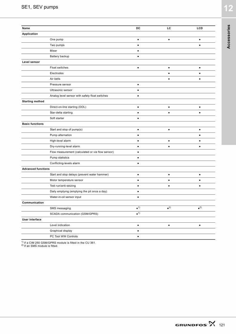
Ac
ce
ss
ori
es
SE1, SEV pumps 12
1) If a CIM 250 GSM/GPRS module is fitted in the CU 361.2) If an SMS module is fitted.
Name DC LC LCD
Application
One pump ● ● ●
Two pumps ● ●
Mixer ●
Battery backup ●
Level sensor
Float switches ● ● ●
Electrodes ● ●
Air bells ● ●
Pressure sensor ●
Ultrasonic sensor ●
Analog level sensor with safety float switches ●
Starting method
Direct-on-line starting (DOL) ● ● ●
Star-delta starting ● ● ●
Soft starter ●
Basic functions
Start and stop of pump(s) ● ● ●
Pump alternation ● ●
High-level alarm ● ● ●
Dry-running-level alarm ● ● ●
Flow measurement (calculated or via flow sensor) ●
Pump statistics ●
Conflicting-levels alarm ●
Advanced functions
Start and stop delays (prevent water hammer) ● ● ●
Motor temperature sensor ● ● ●
Test run/anti-seizing ● ● ●
Daily emptying (emptying the pit once a day) ●
Water-in-oil sensor input ●
Communication
SMS messaging ●1) ●2) ●2)
SCADA communication (GSM/GPRS) ●1)
User interface
Level indication ● ● ●
Graphical display ●
PC Tool WW Controls ●
121
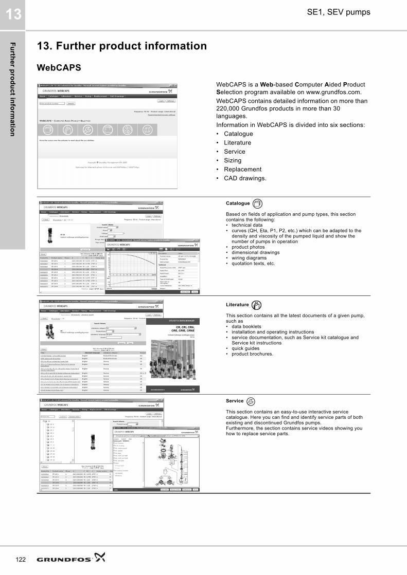
Fu
rthe
r pro
du
ct in
form
atio
n
122
SE1, SEV pumps13
13. Further product information
WebCAPS
WebCAPS is a Web-based Computer Aided Product Selection program available on www.grundfos.com.
WebCAPS contains detailed information on more than 220,000 Grundfos products in more than 30 languages.
Information in WebCAPS is divided into six sections:
• Catalogue
• Literature
• Service
• Sizing
• Replacement
• CAD drawings.
Catalogue
Based on fields of application and pump types, this section contains the following:• technical data• curves (QH, Eta, P1, P2, etc.) which can be adapted to the
density and viscosity of the pumped liquid and show the number of pumps in operation
• product photos• dimensional drawings• wiring diagrams• quotation texts, etc.
Literature
This section contains all the latest documents of a given pump, such as• data booklets• installation and operating instructions• service documentation, such as Service kit catalogue and
Service kit instructions• quick guides• product brochures.
Service
This section contains an easy-to-use interactive service catalogue. Here you can find and identify service parts of both existing and discontinued Grundfos pumps.Furthermore, the section contains service videos showing you how to replace service parts.
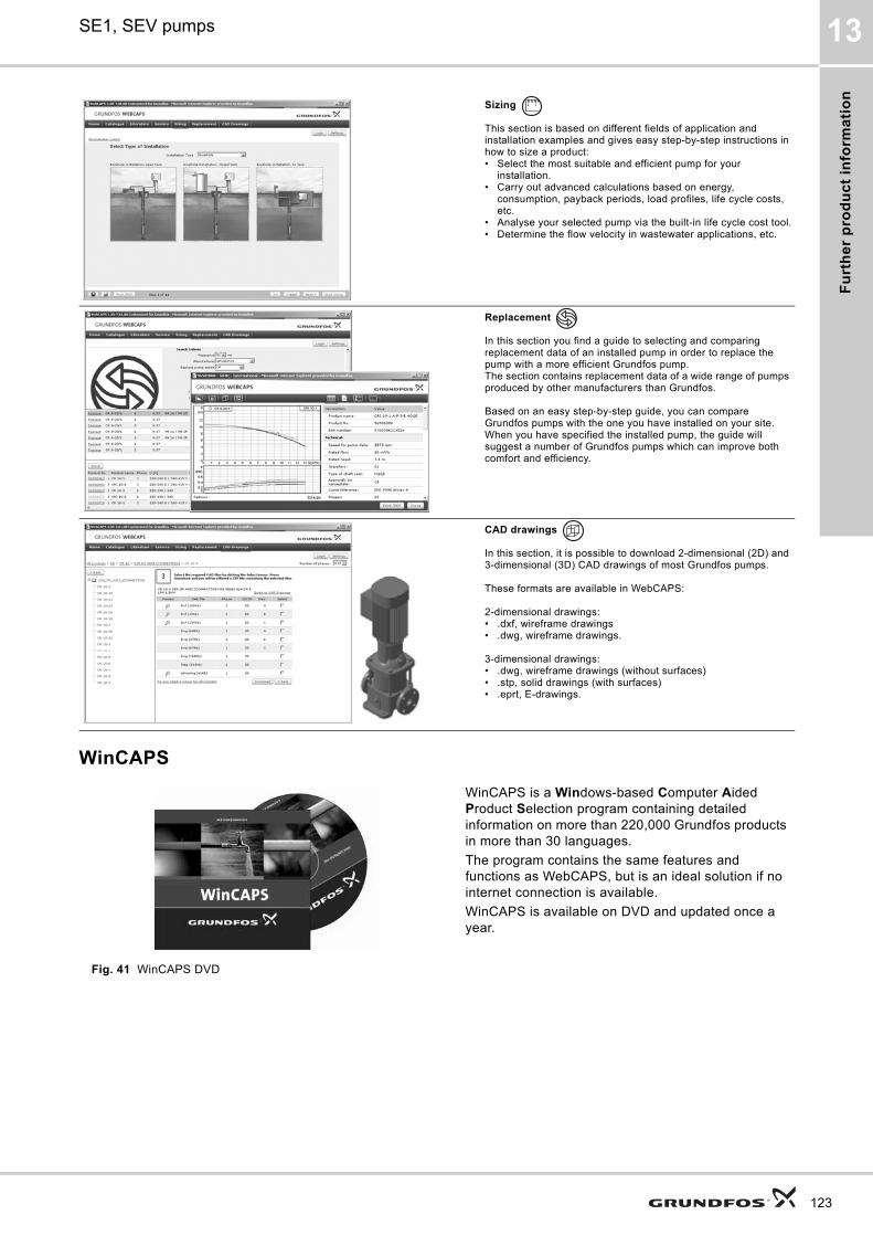
Fu
rth
er
pro
du
ct
info
rma
tio
n
SE1, SEV pumps 13
WinCAPS
Fig. 41 WinCAPS DVD
Sizing
This section is based on different fields of application and installation examples and gives easy step-by-step instructions in how to size a product:• Select the most suitable and efficient pump for your
installation.• Carry out advanced calculations based on energy,
consumption, payback periods, load profiles, life cycle costs, etc.
• Analyse your selected pump via the built-in life cycle cost tool.• Determine the flow velocity in wastewater applications, etc.
Replacement
In this section you find a guide to selecting and comparing replacement data of an installed pump in order to replace the pump with a more efficient Grundfos pump. The section contains replacement data of a wide range of pumps produced by other manufacturers than Grundfos.
Based on an easy step-by-step guide, you can compare Grundfos pumps with the one you have installed on your site. When you have specified the installed pump, the guide will suggest a number of Grundfos pumps which can improve both comfort and efficiency.
CAD drawings
In this section, it is possible to download 2-dimensional (2D) and 3-dimensional (3D) CAD drawings of most Grundfos pumps.
These formats are available in WebCAPS:
2-dimensional drawings:• .dxf, wireframe drawings• .dwg, wireframe drawings.
3-dimensional drawings:• .dwg, wireframe drawings (without surfaces)• .stp, solid drawings (with surfaces)• .eprt, E-drawings.
WinCAPS is a Windows-based Computer Aided Product Selection program containing detailed information on more than 220,000 Grundfos products in more than 30 languages.
The program contains the same features and functions as WebCAPS, but is an ideal solution if no internet connection is available.
WinCAPS is available on DVD and updated once a year.
0 1
123
Fu
rthe
r pro
du
ct in
form
atio
n
124
SE1, SEV pumps13
GO CAPS
Mobile solution for professionals on the GO!
CAPS functionality on the mobile workplace.
Subject to alterations.

125

126

127
GRUNDFOS A/S DK-8850 Bjerringbro . DenmarkTelephone: +45 87 50 14 00www.grundfos.com
97756118 0114
ECM: 1115361 Th
e n
am
e G
run
dfo
s, t
he
Gru
nd
fos
log
o,
an
d b
e t
hin
k i
nn
ov
ate
are
re
gis
tere
d t
rad
em
ark
s o
wn
ed
by
Gru
nd
fos
Ho
ldin
g A
/S o
r G
run
dfo
s A
/S,
De
nm
ark
. A
ll ri
gh
ts r
ese
rve
d w
orl
dw
ide
.©
Co
pyr
igh
t G
run
dfo
s H
old
ing
A/S