S.E. Exam Review: Prestressed Concrete · Reinforced concrete and prestressed concrete are now...
65
S.E. Exam Review: Prestressed Concrete Richard A. Miller, PE, FPCI [email protected] Distribution of the webinar materials outside of your site is prohibited. Reproduction of the materials and pictures without a written permission of the copyright holder is a violation of the U.S. law. Applicable Specifications 5 General Information 8 Phi Factors, Section Types 14 Basic Equation of Prestressing 18 ACI Classes of Prestressed Sections 20 Design Example General 22 Losses (PCI Method) 28 Service Load Behavior 40 Table of Contents 2
Transcript of S.E. Exam Review: Prestressed Concrete · Reinforced concrete and prestressed concrete are now...
S.E. Exam Review:Prestressed Concrete
Richard A. Miller, PE, [email protected]
Distribution of the webinar materials outside of your site is prohibited. Reproduction of the materials and pictures without a written permission of the copyright holder is a violation of the U.S. law.
� Applicable Specifications 5
� General Information 8
� Phi Factors, Section Types 14
� Basic Equation of Prestressing 18
� ACI Classes of Prestressed Sections 20
� Design Example General 22
� Losses (PCI Method) 28
� Service Load Behavior 40
Table of Contents
2

� Strength Limit State 45
� Ductility Limit 51
� Development Length 53
� Debonding 54
� Shear General 55
� Shear, Simplified Method 59
� Shear, Stirrups 66
� Shear, and 69
� Release Stresses 87
Table of Contents
3
� Release Stresses/Harping 96
� Service Stresses/Harping 106
� Shear/Harping 108
� Camber/Deflection 118
Table of Contents
4
�Buildings:�ACI 318-14�Reorganized by member type (e.g. beam, column, slab)
rather than stress (e.g. flexural, shear).�Reinforced concrete and prestressed concrete are now
mixed together in the code.�Common material is now in “toolbox” chapters. � There is no separate chapter on prestressed any more.
�PCI Design Handbook 7th Ed (covers pretensioned) based on ACI 318-08/11� 8th Edition came out in 2018; based on ACI 318-14�NCEES no longer names a PCI Handbook
Applicable Specifications
5
�Due to time limitations, only pretensioned under gravity loads can be covered.
� It is assumed that the participant knows how to calculate the critical loads and load combinations per ASCE 7.
�We will analyze a building beam.� ACI 318 – 14� PCI Design Handbook, 7th Ed.
� For prestressed concrete, many building concepts are applicable to bridges.
�PCI has information (including FREE information) on bridge design. Check the website pci.org for information.
This Webinar
6

Exam Areas Covered
7
Day AreaApprox.
% on Exam
Friday Morning
Analysis of Structures – Load 10%Analysis of Structures – Methods 20%Design and Details of Structures – General Considerations 7.5%
Design and Details of Structures – Concrete 12.5%Friday Afternoon Concrete Building Structures 25%*Lateral loads (Saturday exam) are not covered in this module.
Note: This module only covers gravity loads. Lateral design of prestressedstructures is a very specialized area which is beyond the scope of a 2 hour webinar.
� Determine loads/moments
� Estimate cross section/reinforcing
� Determine loss of prestressing force
� Check service load stresses
� Check nominal bending strength ( )
� Check release stresses
� Check shear
� Miscellaneous checks
Steps in Prestress Design
8
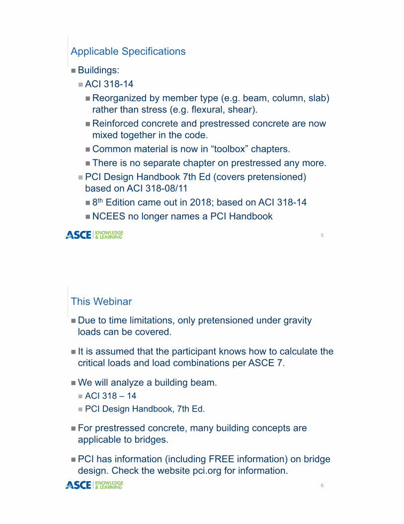
�Pretensioned� 7 wire strand is anchored
to end supports.�Concrete is cast around
the strand.�When the concrete
reaches strength, the strand is cut releasing the prestressing.
� Force is transferred through bond.
Types of Prestressed Concrete – Pretensioned
9
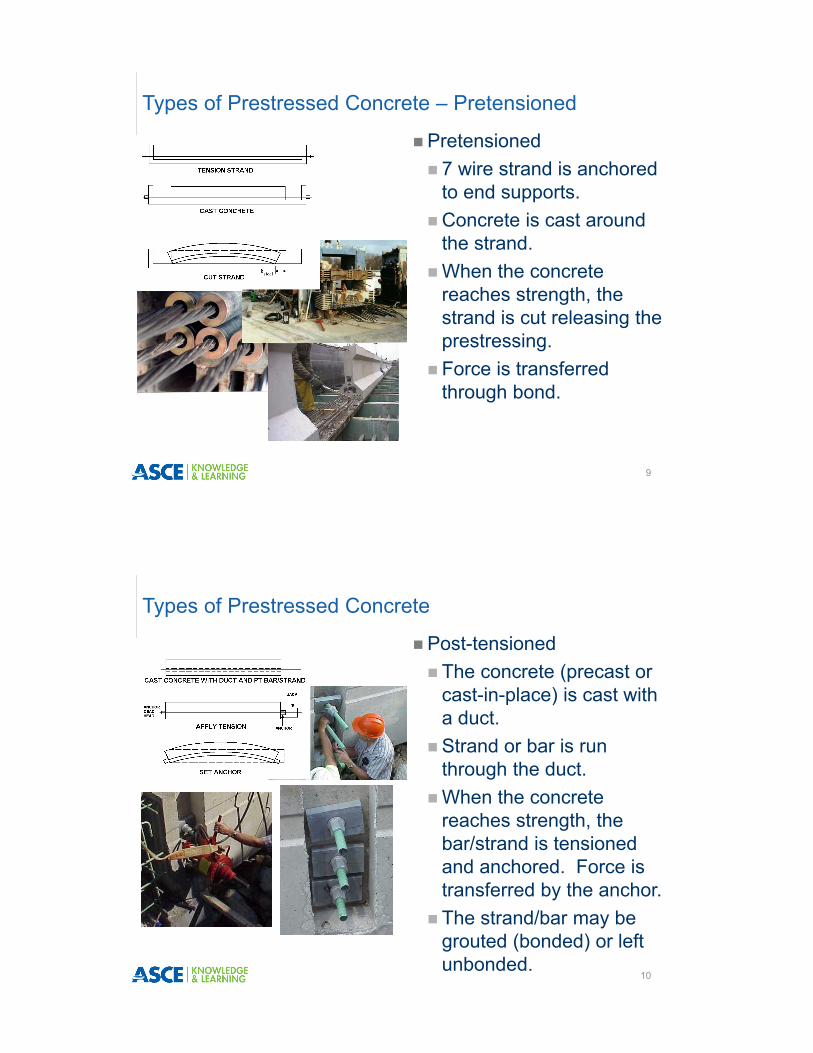
�Post-tensioned� The concrete (precast or
cast-in-place) is cast with a duct.
�Strand or bar is run through the duct.
�When the concrete reaches strength, the bar/strand is tensioned and anchored. Force is transferred by the anchor.
� The strand/bar may be grouted (bonded) or left unbonded.
Types of Prestressed Concrete
10

� At transfer of prestressing force:� Different allowable stresses for compression in the concrete and tension in the steel� In post tensioned, there are limits on bearing stresses in the concrete due to anchorage
devices
� At service loads � No difference between methods
� At ultimate load� A different formula is used for the steel stress, fps, for if unbonded steel is used in post-
tensioned structures.� No difference between methods, otherwise
� Prestressing force losses� There are some differences for each method
� Concrete Strength:� The term = concrete strength when prestressing is applied� The term = design concrete strength (usually 28 or 56 d)
Post-tensioning vs. Pretensioning
11
� ASTM A416
� 7 wire – helically wrapped.
� Strength: GR 250 = 250 ksi or GR 270 = 270 ksi
� Stress Relieved (less common) or Low Relaxation (more common)
� Common Diameters: 3/8”, ½”, ½” special, 0.6”.
� 28,500ksi due to helical wrap
� Areas found in tables.
Tables with areas of strands can be found in the PCI Design Handbook, prestressed concrete text books or on the web from manufacturers.
Prestressing Strand
12

h = overall height of the section.d = distance from compression face to centroid of all tensile steel. May be limited 0.8 .= distance from compression face to centroid of prestressing steel only. May or
may not limited to 0.8 .= distance from compression face to centroid of extreme tensile steel (mild or
prestressed).e = distance from centroid of gross section to centroid of prestressing steel, only. Called eccentricity.
Important ACI Definitions
13
Compression Face
d h
e
Definition of Section Types (ACI 21.2.2)
14
Strain in the extreme tensile steel, εt
Type of Section I
⁄ Compression Controlled⁄ 3 5⁄ *
0.65 Tied Conf.0.75 Spiral Conf.
0.005 ⁄ Transition3 8⁄ ⁄ 3 5⁄ * Interpolated based on εt
0.005 Tension Controlled⁄ 3 8⁄ 0.9
*For Grade 60 steel and prestressing steel, where fy/Es may be taken as 0.002.
Compression Face
c
0.003
The same definition is used for both building and bridge for prestressing steel, which is the same as for Grade 60 mild reinforcing.
Note: ACI states a flexural member ( 0.1 ) must have 0.004; this does not apply to prestressed members. See 9.3.3.1.

� ℓ = development length;� Length the strand needs to be bonded to develop the full nominal moment,
Mn. � The stress in the strand at Mn is called fps.
� ℓ = transfer length;� Length the strand needs to be bonded to develop the service load stresses.� Service load stress in the strand is called fse.
The equations, which will be covered in detail later, are:
ℓ3,000 1,000
ℓ3,000
Units are psi for fps and fse; db is nominal strand diameter.
Definition of Development and Transfer Lengths
15
16
Debonding
To control stresses at the end of a girder, strand is sometimes “debonded”. Reasons for this are explained later.
Note the Teflon sleeves placed around some of the strand. This is “debonding”. These strand will not bond over the coated length. This strand behaves as though it begins at the end of the sleeve.

Strength reduction factors (ϕ) at the ends of pretensioned members (21.2.3).ℓ = development length; ℓ = transfer length ℓ = debonded length
Requirements for End Conditions
17
Condition at end of member
Stress in concrete under service load1
Distance from end of member to section under
considerationI
All strands bonded Not applicableℓ 0.75 (a)
ℓ to ℓ Linear Interpolation from 0.75 to 0.902 (b)
One or more strands debonded
No tension calculatedℓ ℓ 0.75 (c)
ℓ ℓ to ℓ ℓ Linear Interpolation from 0.75 to 0.902 (d)
Tension Calculated
ℓ ℓ 0.75 (e)
ℓ ℓ to ℓ 2ℓ Linear Interpolation from 0.75 to 0.902 (f)
1Stresses calculated using gross cross sectional properties in extreme fiber of precompressed tension zone under service loads after allowance for all prestress losses at section under service conditions.
2It shall be permitted to use a strength reduction factor of 0.75.
The basic equation of prestressing (for both buildings and bridges):
Basic Equation of Prestressing
18
ee
PP
w
PP
w
=
BendingCompression
AxialCompression Tension
Tension Compression Compression Compression Compression
Compression CompressionTension (small)
Tension (small)
∓=
Sum
The eccentric prestressing force causes both axial compression and bending opposite to the applied forces. In cases where the section can be considered elastic, the net stress is found from superposition. This equation applies at release of prestressing force and under service load.

∓
= concrete stress (+ = comp; - = tens).
P = total prestressing force after all loses
e = eccentricity
c = distance from neutral axis to extreme fiber. There may be different values of “c” for top and bottom!
M = moment from external forces
= gross area
= gross moment of inertia
For a simply supported beam, the top sign is for the stress at the top of the beam and the bottom sign is for the stress at the bottom of the beam.
Basic Equation of Prestressing
19
If the section is made composite by adding a slab later, the loads must be separated based on whether they were applied to non-composite precast section or to the entire composite section. This is not difficult, it just requires bookkeeping. The basic equation becomes:
∓
Where “nc” refers to the non-composite section properties and the forces/moments applied to the non-composite section and “comp” refers to the properties and moments applied to the composite section.
Basic Equation of Prestressing
20
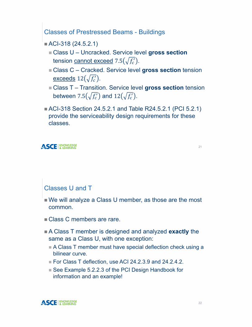
�ACI-318 (24.5.2.1)�Class U – Uncracked. Service level gross section
tension cannot exceed 7.5 .�Class C – Cracked. Service level gross section tension
exceeds 12 .�Class T – Transition. Service level gross section tension
between 7.5 and 12 .
�ACI-318 Section 24.5.2.1 and Table R24.5.2.1 (PCI 5.2.1) provide the serviceability design requirements for these classes.
Classes of Prestressed Beams - Buildings
21
�We will analyze a Class U member, as those are the most common.
�Class C members are rare.
�A Class T member is designed and analyzed exactly the same as a Class U, with one exception:� A Class T member must have special deflection check using a
bilinear curve.� For Class T deflection, use ACI 24.2.3.9 and 24.2.4.2.� See Example 5.2.2.3 of the PCI Design Handbook for
information and an example!
Classes U and T
22
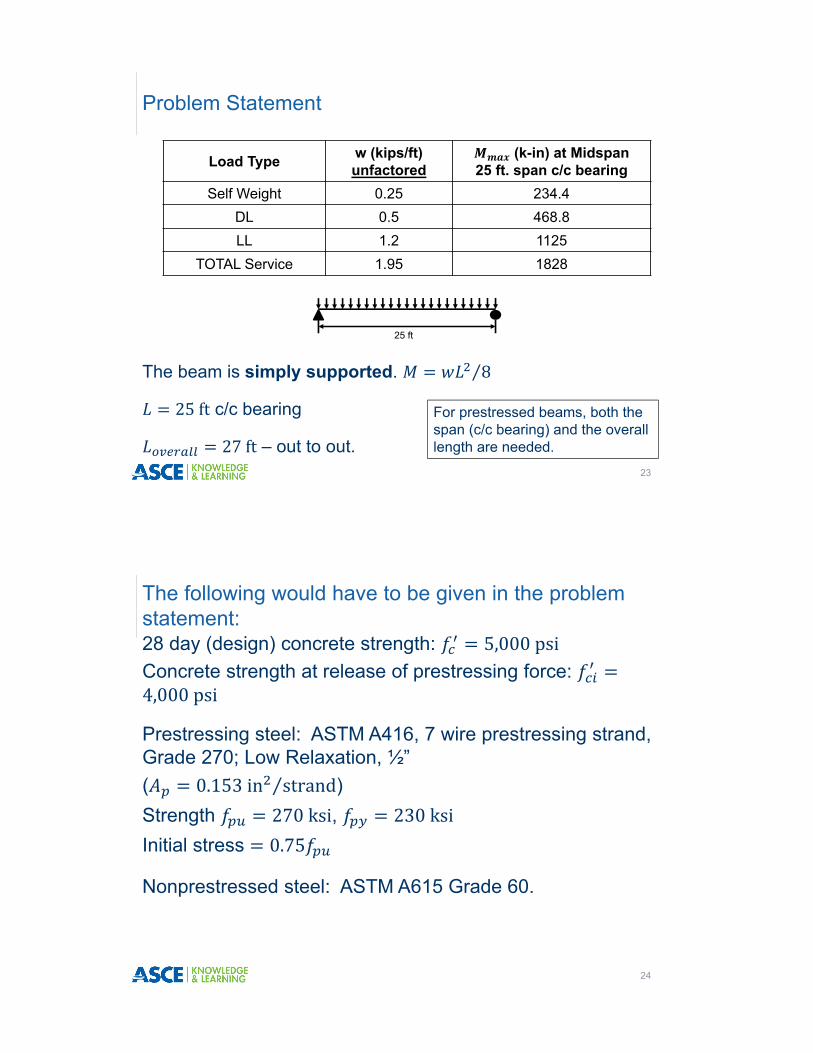
The beam is simply supported. 8⁄
25ft c/c bearing
27ft – out to out.
Problem Statement
23
For prestressed beams, both the span (c/c bearing) and the overall length are needed.
Load Type w (kips/ft)unfactored
(k-in) at Midspan 25 ft. span c/c bearing
Self Weight 0.25 234.4DL 0.5 468.8LL 1.2 1125
TOTAL Service 1.95 1828
25 ft
28 day (design) concrete strength: 5,000psiConcrete strength at release of prestressing force: 4,000psi
Prestressing steel: ASTM A416, 7 wire prestressing strand, Grade 270; Low Relaxation, ½”( 0.153in strand⁄ )Strength 270ksi, 230ksiInitial stress 0.75
Nonprestressed steel: ASTM A615 Grade 60.
The following would have to be given in the problem statement:
24

Initial prestressing force in the strand
0.75 0.75 270ksi 202.5ksi
This is the stress in the steel before release. This is not standard and would have to be given.
20.3.2.5.1 Limits on Prestressing Steel Stress:
Due to jacking 0.94 0.94 230 216ksi
0.8 216ksi
After transfer of prestressing – None for pretensioned. (provision removed in 2011)
Prestressing Steel
25
This is a partial reproduction of a table on Pg 3-44 of the 7th Edition of the PCI Design Handbook. It covers rectangular beams. The span is 25 feet and the load is 1,950 pounds/ft. Use a 12RB20. The approximate service load with 8 strands is 2,410 pound/ft.
Initial Section Selection
26
Section # ½”Str
Approximate Service Load pound/ft for a given span (in feet) –Assumed 50% DL + 50% LL
16 18 20 22 24 26 28 30 32 34 36
12RB16 5 3,350 2,770 2,210 1,790 1,480 1,230 1,040
12RB20 8 6,160 4,820 3,860 3,150 2,620 2,200 1,860 1,600 1,380 1,190 1,040
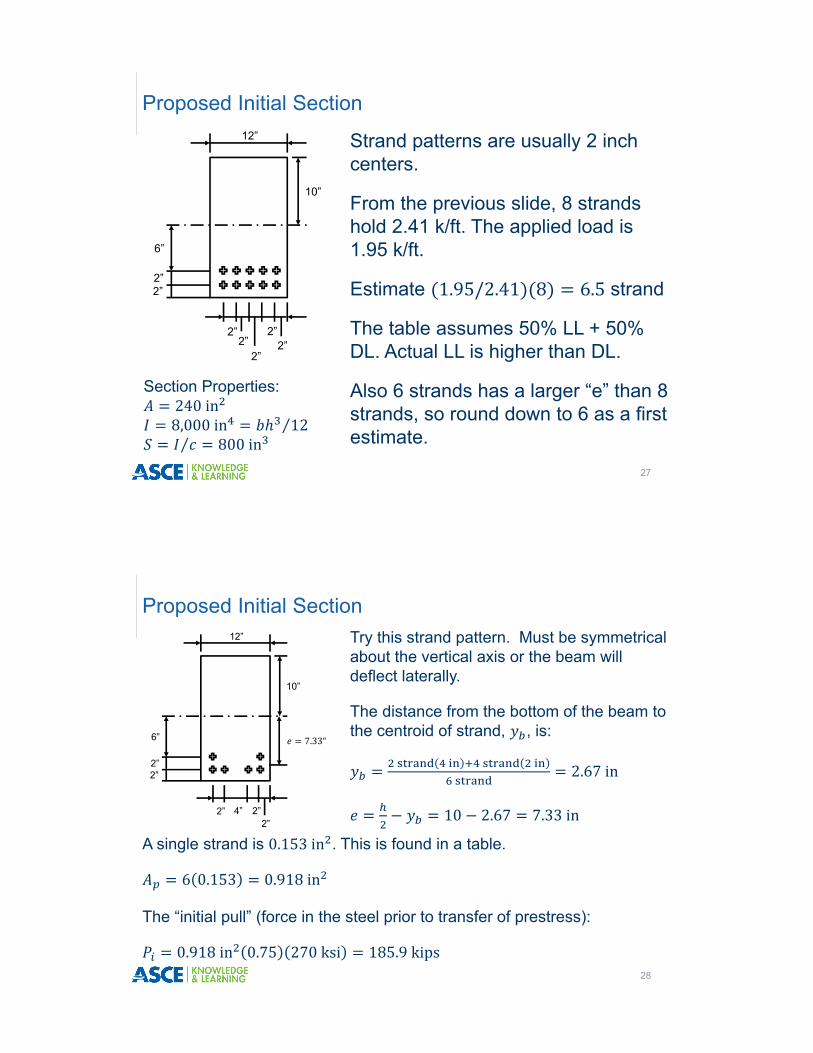
Strand patterns are usually 2 inch centers.
From the previous slide, 8 strands hold 2.41 k/ft. The applied load is 1.95 k/ft.
Estimate 1.95/2.41 8 6.5 strand
The table assumes 50% LL + 50% DL. Actual LL is higher than DL.
Also 6 strands has a larger “e” than 8 strands, so round down to 6 as a first estimate.
Proposed Initial Section
27
12”
10”
6”
2”2”
2”2”
2”
2”2”
Section Properties:240in8,000in 12⁄⁄ 800in
Try this strand pattern. Must be symmetrical about the vertical axis or the beam will deflect laterally.
The distance from the bottom of the beam to the centroid of strand, , is:
2.67in
10 2.67 7.33in
Proposed Initial Section
28
12”
10”
6”
2”2”
2” 4” 2”2”
7.33“
A single strand is 0.153in . This is found in a table.
6 0.153 0.918in
The “initial pull” (force in the steel prior to transfer of prestress):
0.918in 0.75 270 ksi 185.9 kips

As soon as the prestressing force is applied, creep, shrinkage and relaxation cause the prestressing force to start to drop. After a long time, this loss of prestressing force stabilizes. These losses are needed for various calculations.
ACI 318 does not say how to calculate the loss of prestressing force, so the procedure in the PCI Design Handbook 7th Ed. (Section 5.7.3 starting on pg. 5-84) is used.
(8th ed. procedure is same as in 7th ed.)
Loss of Prestressing
29
(20.3.2.6.1) The losses are Elastic shortening; Creep of the concrete; Shrinkage of the concrete and Relaxation of the steel. These apply to both pre and post tensioned.
Post tensioned also has anchorage set loss and loss due the friction when the tendons are pulled through curved ducts.
Losses are for service load calculations. Unfactored loads are used.
Loss of Prestressing
30

The elastic moduli are needed (ACI 19.2.2.1 for concrete). Note that there are two; one for release and one for service level stresses. E is given for 145 pcf concrete.
The prestressing steel value is from the appendix of the PCI Design Handbook. It is less than 29,000,000 psi due to the helical wrap of the prestressing strand.
33 145 . 4,000 3,600,000psi
33 145 . 5,000 4,030,000psi
28,500,000psi
Elastic Modulus of Concrete
31
When the steel is cut, it “springs” back, compressing the concrete. Since the steel and concrete are bonded, the steel shortens and loses stress.
This is elastic shortening.
Elastic Shortening
32

∆
∆ ∆
Elastic Shortening
33
This is the stress in concrete at the centroid of the steel at release. is an empirical constant = 0.9.
Since concrete and steel are bonded, the change in steel strain is equal to the concrete strain.
Elastic shortening is the change in steel stress. is an empirical constant = 1.
Normally, prestressed beams are cast longer than the center of bearing to center of bearing span to allow for the width of bearing pads. This beam is cast 27 feet long.
1. When calculating the stress when the prestressing is released (release condition), it is usual to use overall length; 27 feet in this case.
2. When calculating stresses under service or ultimate loads, center of bearing to center of bearing span is used; 25 feet in this case.
3. If overall length is not given, the c/c bearing can be used for the release condition; some example problems even use c/c bearing at release.
Span Length Definitions
34

From the PCI Handbook, 0.9. The term is the concrete stress at the centroid of the steel (in My/I use y = e). The only load is the beam’s own DL.
185.9k and 7.33 in (found prev.).
. ⁄ 12 in ft⁄ 273.4k in
0.9 .
. . ,
. . ,
1.57ksi
Calculation of fcir
35
1.0 is from the PCI Design Handbook
57,000 4,000 3,600,000psi
1.0 , ,
1.57ksi 12.5ksi
For post-tensioned structures, the ES equation above is valid if all tendons are tightened simultaneously. If they are tightened one at a time, ES above is multiplied by (N-1)/2N; where N is the number of tendons. The following equations for CR, SH and RE work for post tensioning, too.
Elastic Shortening Loss
36
Since this is normal wt. concrete, here is an alternate
equation.

Because the prestressing force keeps a constant stress on the concrete, the concrete will creep. Creep shortens the beam and causes a loss of prestressing. Additional DL moments mitigate these stresses, so they are subtracted out. Self weight is already subtracted out of the term. Again, stress is found at . The additional dead load is applied after the beam is in place, so the c/c bearing (service load) span is used.
. ⁄ 12 in ft⁄ 468.8k in
. . ,
0.43ksi
2.0
2.0 , ,
1.57ksi 0.43ksi 16.4ksi
Creep Loss
37
Elastic strain in concrete from sustained loads. The concrete is assumed 28 days old. 2 is the creep coefficient.
This shows the loss due to shrinkage of the concrete. The volume to surface area ratio (V/S) is approximated by the area to perimeter ratio. Relative Humidity varies; here it is taken as 70%. There is a map in the PCI Design Handbook (pg 3-114) which gives local RH values.
8.2 10 1 0.06 100
8.2 10 1 28,500ksi 1 0.06 3.75 100 70
5.43ksi
Shrinkage Loss
38

Finally, steel under stress relaxes. The relaxation loss is:
The values of , J and C are found in the PCI Design Handbook (Pg 5-84). For Grade 270 low relaxation steel initially stressed to 0.75 ; 5,000psi, 0.04 and 1.0.
5ksi 0.04 12.5 16.4 5.4 1.0
3.7ksi
Total 12.5 16.4 5.4 3.7 38ksi
. 100% 19%
Relaxation Loss and Total Loss
39
Thus, the stress in the strand after all losses is:
0.75 loss 0.75 270ksi 38ksi 164ksi
6strand 0.153in 164ksi 150.5k
This will be the stress in the strand after a long time.
It is used to calculate service load behavior.
Typical loss values are 15-30%, with 20% being average.
Effective Stress
40
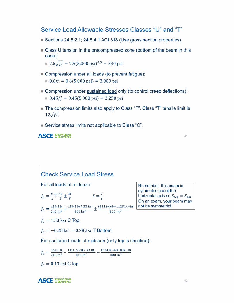
� Sections 24.5.2.1; 24.5.4.1 ACI 318 (Use gross section properties)
� Class U tension in the precompressed zone (bottom of the beam in this case):
� 7.5 7.5 5,000psi . 530psi
� Compression under all loads (to prevent fatigue):� 0.6 0.6 5,000psi 3,000psi
� Compression under sustained load only (to control creep deflections):� 0.45 0.45 5,000psi 2,250psi
� The compression limits also apply to Class “T”. Class “T” tensile limit is 12 .
� Service stress limits not applicable to Class “C”.
Service Load Allowable Stresses Classes “U” and “T”
41
For all loads at midspan:
∓
.
∓ . .
1.53ksi C Top
0.28ksi 0.28 T Bottom
For sustained loads at midspan (only top is checked):
.
. .
. .
0.13ksi C top
Check Service Load Stress
42
Remember, this beam is symmetric about the horizontal axis so . On an exam, your beam may not be symmetric!
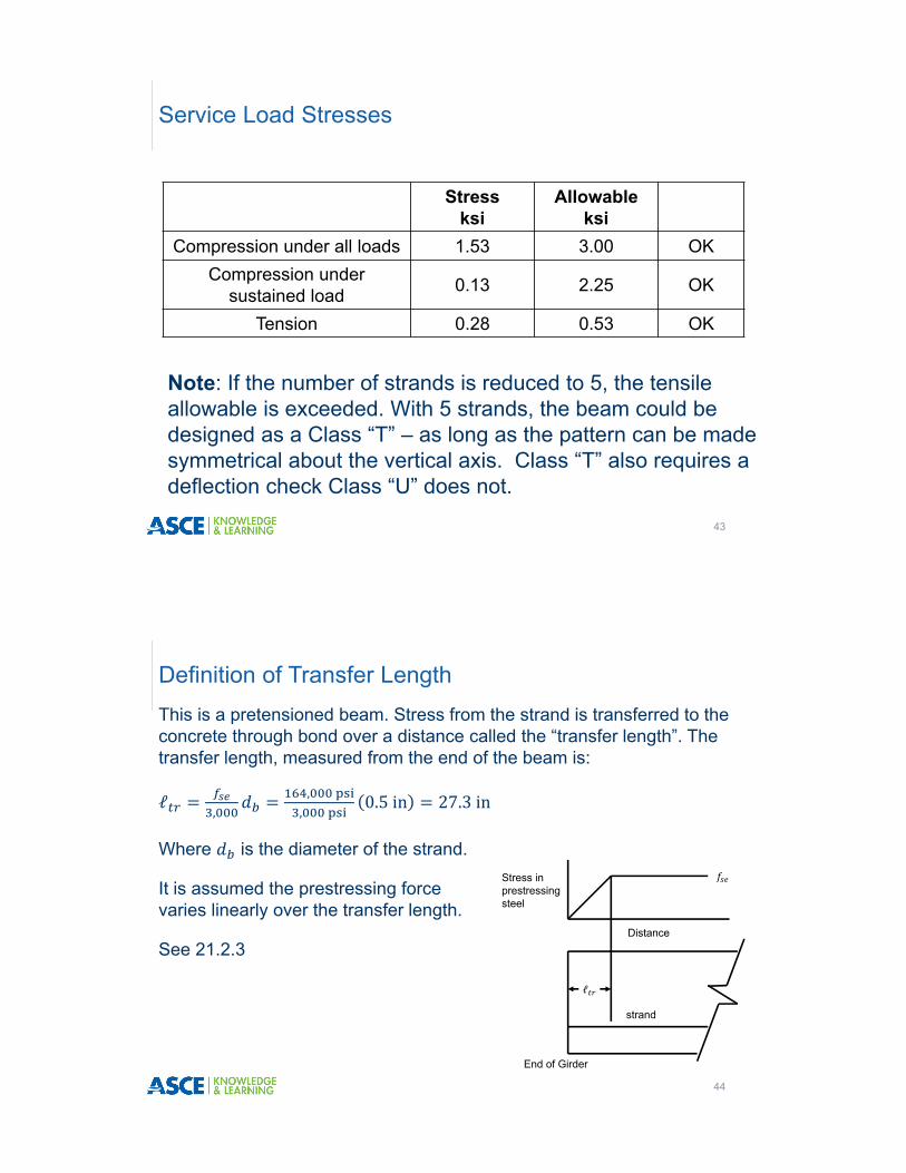
Note: If the number of strands is reduced to 5, the tensile allowable is exceeded. With 5 strands, the beam could be designed as a Class “T” – as long as the pattern can be made symmetrical about the vertical axis. Class “T” also requires a deflection check Class “U” does not.
Service Load Stresses
43
Stress ksi
Allowable ksi
Compression under all loads 1.53 3.00 OKCompression under
sustained load 0.13 2.25 OK
Tension 0.28 0.53 OK
This is a pretensioned beam. Stress from the strand is transferred to the concrete through bond over a distance called the “transfer length”. The transfer length, measured from the end of the beam is:
ℓ,
, ,
0.5in 27.3in
Where is the diameter of the strand.
It is assumed the prestressing force varies linearly over the transfer length.
See 21.2.3
Definition of Transfer Length
44
Stress in prestressing steel
ℓ
Distance
strand
End of Girder

This graph shows the stresses from applying all service loads are below the allowable along the entire beam. A similar graph would show top stress under sustained service loads is below the allowable at all points. The stress does not go to 0 at the supports because the beam overhangs the supports by 1 foot.
Service Load Stresses
45
‐0.8
0
0.8
1.6
2.4
3.2
0 5 10 15 20 25
Stress, ksi
Length ‐ feet
Compression allowable = 3 ksi
Tension allowable = ‐0.53 ksi
Bottom StressTop Stress
Linear reduction of prestressing force over transfer length
Unlike reinforced concrete, the steel stress is not assumed as yield, but must be calculated. This equation is valid if 0.5 :
1
Ignore any compression steel if the following conditions are not met:
0.17
And
0.15
Strength Limit State 20.3.2.3.1
46

stress in the prestressing steel at the ultimate condition
ultimate strength of the prestressing steel
yield strength of the prestressing steel
concrete design strength
prestressing steel constant
0.55 for ⁄ 0.8 (prestressing bar)0.4 for ⁄ 0.85 (stress relieved strand)0.28 for ⁄ 0.9 (low relaxation strand)
the stress block constant for concrete0.85 for 4,000psi0.65 for 8,000psiinterpolate in between
Strength Limit State 20.3.2.3.1
47
Strength Limit State 20.3.2.3.1
48
effective depth of the prestressing steel. (Prestressing strand is never considered effective in compression so if there is strand on the compression side, a strain compatibility approach is needed – see PCI Handbook)
width of the compression face
effective depth to the tensile steel
depth to non-prestressed, compression steel.
Careful, it’s d, not d’!
Since there is no compression steel or non-prestressed tensile steel:
17.3in 0.28 0.8 for 5,000psi
1
270ksi 1 ..
. .
247.4ksi
Strength Limit State 20.3.2.3.1
49
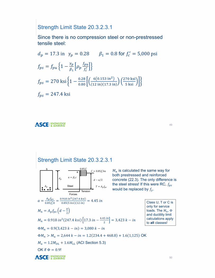
.. . .
4.45
0.918 247.4 17.3 . 3,423
Φ 0.9 3,423 3,080
Φ 2,644 1.2 234.4 468.8 1.6 1,125 OK
1.2 1.6 (ACI Section 5.3)
OK if Φ 0.9!
Strength Limit State 20.3.2.3.1
50
ba
Steel
Tension
0.850.85
2⁄
Forces
is calculated the same way for both prestressed and reinforced concrete (22.3). The only difference is the steel stress! If this were RC, would be replaced by .
Class U, T or C is only for service loads. The , )and ductility limit calculations apply to all classes!

For prestressing steel, tension control, compression control and transition sections are defined the same as for Gr 60 rebar.
Tension control if 0.005. It was shown previously that this condition is met if ⁄ 0.375.
Strength Limit State
51
4.45
. .
5.56
.
0.309 0.375
b
h
c
0.003
Or: 0.003 1 0.003.
1 0.0067 0.005
The section is tension controlled so Φ 0.9.
Remember, is to the extreme tension steel, not the steel centroid.
Now check the ductility limit (minimum steel). ACI 318 (9.6.2.1) requires the ultimate moment to be at least 1.2 times the cracking moment (unless both Φ 2 and Φ 2 ).
Φ 1.2
7.5
If the section is composite:
7.5 1 7.5
Where is the non-composite area, is the non-composite section modulus, is the composite section modulus and are the moments applied only to the non-composite section. P is the effective prestressing force at service load after all losses. This applies to all Classes.
Ductility Limit
52
Taking compression (+) and tension (-)
Φ 1.2
7.5
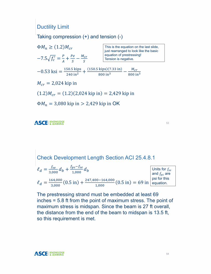
0.53ksi .
. .
2,024kipin
1.2 1.2 2,024kipin 2,429kipin
Φ 3,080kipin 2,429kipin OK
Ductility Limit
53
This is the equation on the last slide, just rearranged to look like the basic equation of prestressing! Tension is negative.
ℓ, ,
ℓ ,,
0.5in , ,,
0.5in 69in
The prestressing strand must be embedded at least 69 inches = 5.8 ft from the point of maximum stress. The point of maximum stress is midspan. Since the beam is 27 ft overall, the distance from the end of the beam to midspan is 13.5 ft, so this requirement is met.
Check Development Length Section ACI 25.4.8.1
54
Units for and are psi for this equation.

55
Check Development Length Section ACI 25.4.8.1
If the strand is “debonded” (a bond breaker is used to lower release stresses), development length is doubled (25.4.8.1).
Note the Teflon sleeves placed around some of the strand. This is “debonding”. These strand will not bond over the coated length. This strand behaves as though it begins at the end of the sleeve.
Development and transfer lengths are calculated from the end of the sleeve.
Shear
56
0
5
10
15
20
25
30
35
40
0 2 4 6 8 10 12
SHEA
R (k)
LENGTH (ft)
FACTORED SHEAR ENVELOPE
CRITICAL SECTION FOR PRESTRESSED IS h/2 FROM FACE OF SUPPORT. ASSUMING 12 IN BEARING PAD, CRITICAL SECTION IS 16 IN FROM CENTER OF BEARING.
V = 31.6 kips
Shear at 6.5 ft = 18.5 kips

� The shear envelope is shown on the previous slide.
� If the section meets ACI 9.4.3.2 – critical section is h/2 from face of support for prestressed.� Support reaction in direction of applied shear.� No concentrated loads between face of support and critical section.� Loads applied to top.
� The term h/2 used because d can be small in a prestressed beam with harped/draped strand.
� Assume beam sits on 12 in bearing pad, so face of support is 6 in from center of bearing. Critical section is 6 20/2 16 in from center of bearing.
Shear – Given
57
�Shear strength for prestressed or non-prestressed concrete is � shear strength of concrete� shear strength of steel� Vertical component of harped strand
� is calculated the same as RC
� for prestressed concrete has two methods;� and (22.5.8.3)�Simplified (22.5.8.2)
Shear
58
The simplified method (22.5.8.2) is shown. is the least of:
0.6 700
1
0.6 700
5
But not less than: 2
In this equation, is the maximum factored moment and is the shear associated with at the section being analyzed. The term is the web width. The term λ is for lightweight. Note: This provision uses both “d” and “ ”; that will be discussed in a later slide!
Shear
59
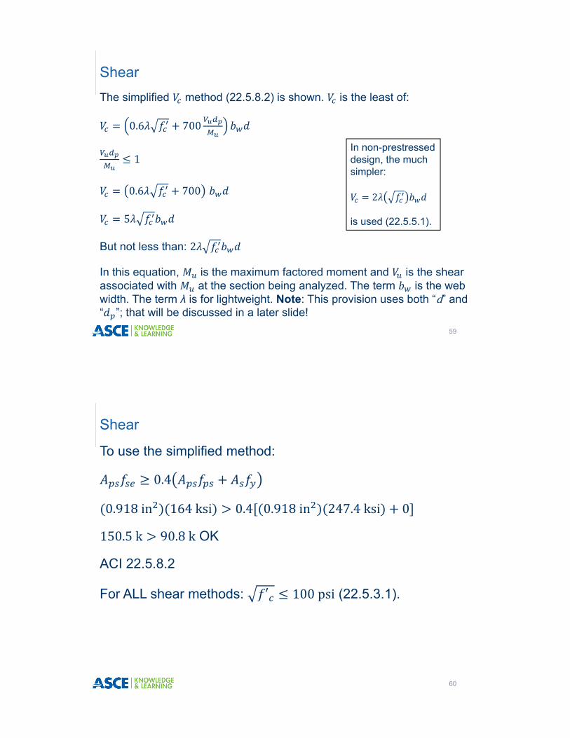
In non-prestressed design, the much simpler:
2
is used (22.5.5.1).
To use the simplified method:
0.4
0.918in 164ksi 0.4 0.918in 247.4ksi 0
150.5k 90.8k OK
ACI 22.5.8.2
For ALL shear methods: ′ 100psi (22.5.3.1).
Shear
60

The beam is divided into intervals, usually, critical section, every 0.1L and any significant points, like a harp point. A shear analysis is performed at each interval.
Time does not permit multiple sections to be analyzed. Rule of thumb: in a prestressed beam, the greatest demand for stirrups is usually at 0.25L. A sample analysis at this section will be performed. This is approximately 6.5 feet from the center of the support.
Shear
61
Shear Envelope
62

From analysis of the beam (using the factored DL of 0.9 klfand factored LL of 1.92 klf) at 6.5 feet from the center of the support:
17kips; 2,035k in. This is the maximum factored moment and the associated shear.
, 18.5k This is the maximum factored shear (different load case)
12inches
Shear
63
LLDL
Load Case for Maximum Moment at Design Section
Load Case for Maximum Shear at Design Section
LLDL
Design Section
17.3 inches
17.3in 0.8h 16in
Note: This provision uses both “d” and “ ”.
Section 22.5.2.1 states that “d” does not need to be less than 0.8h. The term “d” is the distance from the extreme compression fiber to the tensile reinforcement – both prestressed and non-prestressed.
The term is the distance from the extreme compression fiber to the all the prestressed reinforcement. This may be taken less than 0.8h for the simplified method.
Shear
64

0.6 ′ 700
. , . , .
,
29.8k controls 0.75 29.8k 22.4k
0.14 1OK
. , . ,
154k 29.8OK
5 ′ 73.4 29.8OK
But not less than: 2 ′ 29.2k 29.8OK
Shear
65
The term 0.75 for lightweight, 0.85 for sand lightweight and 1 for normal weight. See 8.4.
Shear Demand vs. Capacity
66

Φ 22.4k 18.5k Φ 11.2k
Minimum stirrups are needed (9.6.3.1). Maximum spacing is (9.7.6.2.2):
For 4
� is the lesser of 0.75h or 24 inches
For 4 8
� is the lesser of 0.375h or 12 inches
For 8
� resize the section (22.5.1.2)
, 0; 0.75 15 24 . Use 15 inches.
Shear
67
Non prestressed beams use the same force limits, but the maximum spacings are d/2 or d/4 for non-prestressed. The difference is because d can get small in a prestressed beam with harped strand!
Determine the minimum stirrup area required for a prestressed beam (9.6.3.3):
, 0.75
0.75 5,000psi ,
0.16in (controls)
,
0.15in
Or ,
. , , .
.
0.05in
, 0.05in at 15 inches c/c
Shear
68
This is the same as for a non-prestressed beam.
This applies only to prestressed.
Use the smaller of these two.

The smallest stirrup is a #3, so #3 @ 15 inches would be needed.
If stirrups were required for strength (22.5.10.5.3):
Φ 0.75
Φ
Shear
69
Note: When calculating maximum spacing, minimum stirrup area or required stirrup strength, d for prestressed concrete does not need to be taken less than 0.8h!
As an alternate to the simplified method of shear presented previously, the ACI code allows the use of and (22.5.8.3).
In the shear equation, is the lesser of and .
is the shear that causes a flexural crack to become a diagonal crack. This term controls near the midspan where moment is greatest and flexural cracking occurs.
is the shear that causes web cracking. This term tends to control near the end of the beam.
and
70
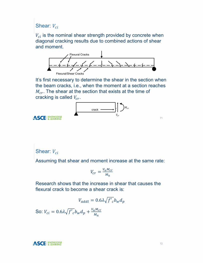
is the nominal shear strength provided by concrete when diagonal cracking results due to combined actions of shear and moment.
Shear:
71
It’s first necessary to determine the shear in the section when the beam cracks, i.e., when the moment at a section reaches
. The shear at the section that exists at the time of cracking is called .
Flexural Cracks
Flexural/Shear Cracks
crack
Assuming that shear and moment increase at the same rate:
Research shows that the increase in shear that causes the flexural crack to become a shear crack is:
0.6 ′
So: 0.6 ′
Shear:
72
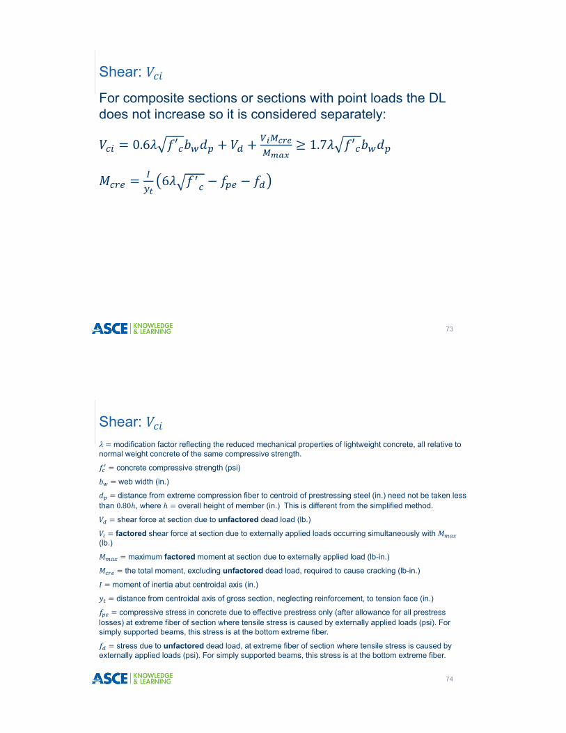
For composite sections or sections with point loads the DL does not increase so it is considered separately:
0.6 ′ 1.7 ′
6
Shear:
73
modification factor reflecting the reduced mechanical properties of lightweight concrete, all relative to normal weight concrete of the same compressive strength.
concrete compressive strength (psi)
web width (in.)
distance from extreme compression fiber to centroid of prestressing steel (in.) need not be taken less than 0.80 , where overall height of member (in.) This is different from the simplified method.
shear force at section due to unfactored dead load (lb.)
factored shear force at section due to externally applied loads occurring simultaneously with (lb.)
maximum factored moment at section due to externally applied load (lb-in.)
the total moment, excluding unfactored dead load, required to cause cracking (lb-in.)
moment of inertia abut centroidal axis (in.)
distance from centroidal axis of gross section, neglecting reinforcement, to tension face (in.)
compressive stress in concrete due to effective prestress only (after allowance for all prestress losses) at extreme fiber of section where tensile stress is caused by externally applied loads (psi). For simply supported beams, this stress is at the bottom extreme fiber.
stress due to unfactored dead load, at extreme fiber of section where tensile stress is caused by externally applied loads (psi). For simply supported beams, this stress is at the bottom extreme fiber.
Shear:
74

The commentary allows (R22.5.8.3 1b and c):
Where:
and are the factored shear and moment;
and are the unfactored dead load shear and moment.
Note that is the shear that occurs simultaneously with .
Shear:
75
For non-composite beams with uniform loads only, the commentary (R22.5.8.3.1d) allows:
0.6 1.7
6
Shear:
76
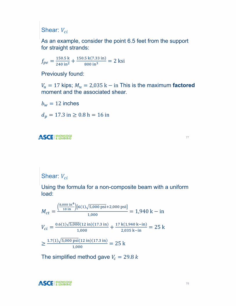
As an example, consider the point 6.5 feet from the support for straight strands:
.
. .
2ksi
Previously found:
17 kips; 2,035k in This is the maximum factoredmoment and the associated shear.
12 inches
17.3in 0.8h 16in
Shear:
77
Using the formula for a non-composite beam with a uniform load:
, , ,
,1,940k in
. , . ,
, ,
25k
. , . ,
25k
The simplified method gave 29.8
Shear:
78
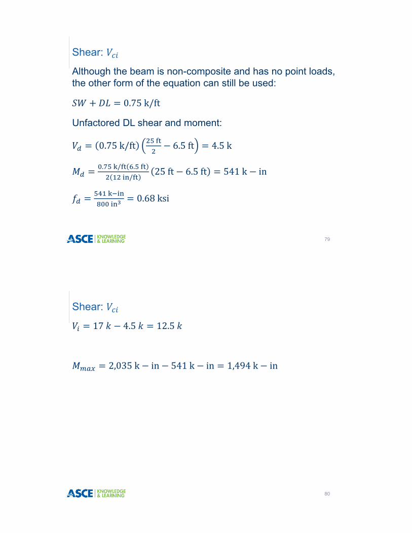
Although the beam is non-composite and has no point loads, the other form of the equation can still be used:
0.75k/ft
Unfactored DL shear and moment:
0.75k/ft 6.5ft 4.5k
. / . /
25ft 6.5ft 541k in
0.68ksi
Shear:
79
17 4.5 12.5
2,035k in 541k in 1,494k in
Shear:
80
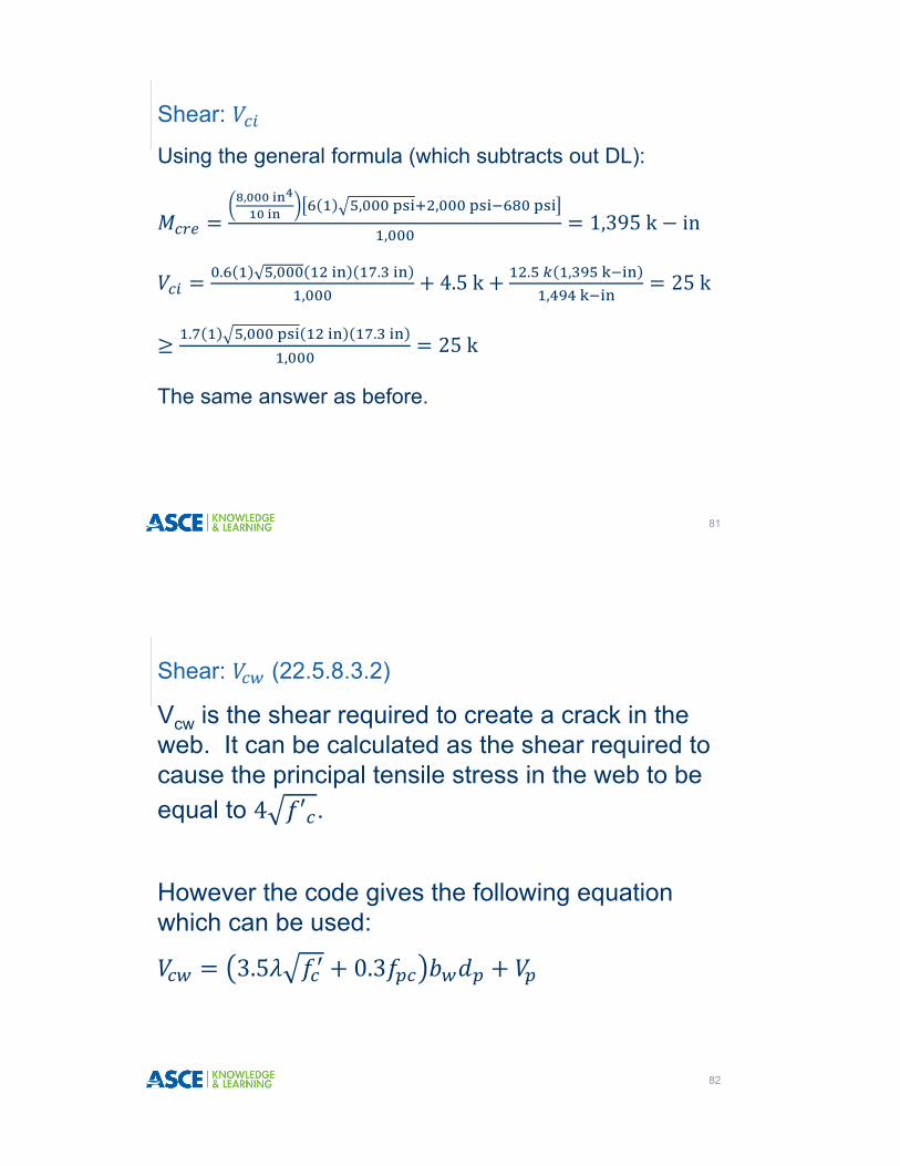
Using the general formula (which subtracts out DL):
, , ,
,1,395k in
. , . ,
4.5k . , ,
25k
. , . ,
25k
The same answer as before.
Shear:
81
Vcw is the shear required to create a crack in the web. It can be calculated as the shear required to cause the principal tensile stress in the web to be equal to .
However the code gives the following equation which can be used:
Shear: (22.5.8.3.2)
82

3.5 0.3
modification factor reflecting the reduced mechanical properties of lightweight concrete, all relative to normal weight concrete of the same compressive strength.
concrete compressive strength (psi)
web width (in.)
distance from extreme compression fiber to centroid of prestressing steel (in.) need not be taken less than 0.80 , where overall height of member (in.)
compressive stress (psi) in concrete (after allowance for all prestress losses) at centroid of cross section resisting externally applied loads or at junction of web and flange when the centroid lies within the flange. For non-composite sections,
⁄ , where effective prestressing force (after allowance for all prestress losses), and cross-sectional area of the member.
vertical component of effective prestress force (for harped strands) at section (lb). This component will be zero for straight prestressing strands.
Shear: (22.5.8.3.2)
83
If the strands are straight, is constant along the beam except within the transfer length where the value of must be reduced for the lack of development. Within the transfer length, is linearly interpolated from 0 at the end of the beam to at the end of the transfer length.
If strands are straight, 0.
3.5 0.3
3.5 1 , ,
0.3 .
12in 17.3in 0
90.4k
Shear:
84
Within the transfer length, is linearly interpolated from 0 at the end of the beam to at the end of the transfer length.
Recall the beam 27 feet long and the span is 25 feet so the beam overhangs the support by 1 foot.
The transfer length, ℓ , was previously found to be 27.3 inches. At 12 inches from the end of the beam (center of bearing) the strand is not fully developed and must be adjusted:
.
150.5k 66.2k
Shear:
85
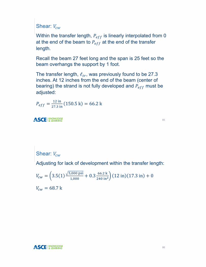
Adjusting for lack of development within the transfer length:
3.5 1 , ,
0.3 .
12in 17.3in 0
68.7k
Shear:
86

Shear Demand vs. Capacity
87
As previously stated, is taken as the lesser of and .
Once is determined by this method, design for shear and design of the stirrups is the same as the simplified method.
Shear: and
88
� Allowables:� Compression 0.6 0.6 4,000psi 2,400psi
� Tension 3 3 4,000 190psi
� Tension at the end of simply supported beam* 6 6 4,000380psi
� Compression at the end of simply supported beam* 0.72,800psi
� If tension limit is exceeded, mild steel must be added.� If the compression limit is exceeded, harp or debond strand.
* ACI does not define what constitutes “the end of a simply supported beam”.
Release Stresses 24.5.3.1
89
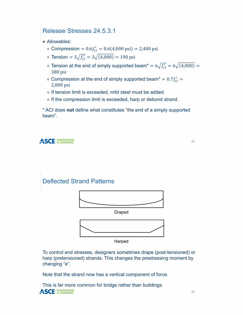
To control end stresses, designers sometimes drape (post-tensioned) or harp (pretensioned) strands. This changes the prestressing moment by changing “e”.
Note that the strand now has a vertical component of force.
This is far more common for bridge rather than buildings.
Deflected Strand Patterns
90
Draped
Harped

� At release, the overall length of the beam is used (27 feet for this example).
� The only applied load is self weight.
� Initial pull is 0.75 202.5ksi
� It is assumed the only loss of prestressing force = ES*.� 6strand 0.153 202.5ksi 12.5ksi 174.4k
� The prestressing force is linearly increased over the transfer length from 0 at the end of the beam to P at the transfer length.
* Not in ACI. Some designers use 10% for the loss at release. Note the stress values of 202.5 ksi and 174 ksi do not violate steel stress limits of 20.3.2.5.1.
Release Stresses
91
Here is a sample calculation of stress at the midspan:
. / 12in/ft 273.4k in
∓
.
∓ . .
.
0.529ksi 0.529ksiTTop
1.98ksi 1.98ksiCBottom
Release Stresses
92
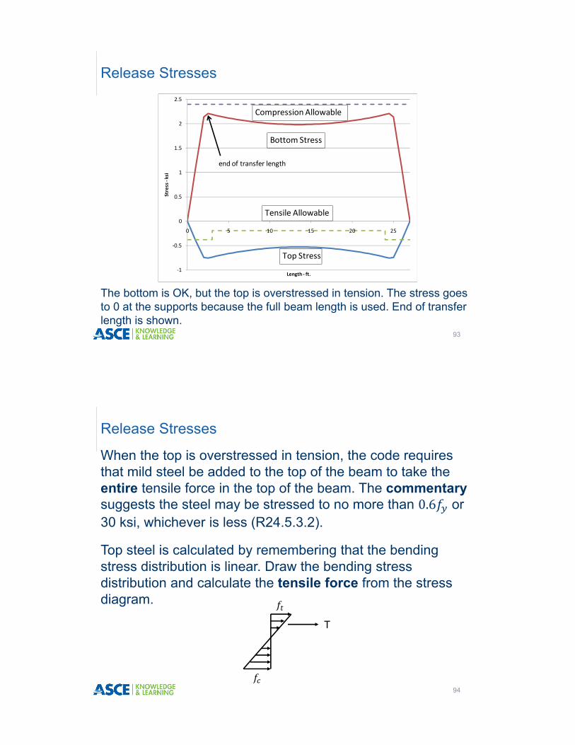
The bottom is OK, but the top is overstressed in tension. The stress goes to 0 at the supports because the full beam length is used. End of transfer length is shown.
Release Stresses
93
‐1
‐0.5
0
0.5
1
1.5
2
2.5
0 5 10 15 20 25
Stress ‐ksi
Length ‐ ft.
Bottom Stress
Top Stress
Tensile Allowable
Compression Allowable
end of transfer length
When the top is overstressed in tension, the code requires that mild steel be added to the top of the beam to take the entire tensile force in the top of the beam. The commentarysuggests the steel may be stressed to no more than 0.6 or 30 ksi, whichever is less (R24.5.3.2).
Top steel is calculated by remembering that the bending stress distribution is linear. Draw the bending stress distribution and calculate the tensile force from the stress diagram.
Release Stresses
94
T
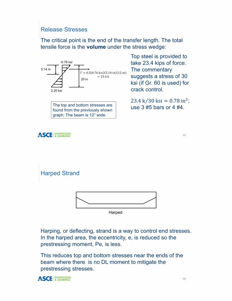
The critical point is the end of the transfer length. The total tensile force is the volume under the stress wedge:
Release Stresses
95
0.5 0.76 5.14 1223.4
-0.76 ksi
2.20 ksi
5.14 in
20 in
Top steel is provided to take 23.4 kips of force. The commentary suggests a stress of 30 ksi (if Gr. 60 is used) for crack control.
23.4k 30ksi⁄ 0.78in ; use 3 #5 bars or 4 #4.The top and bottom stresses are
found from the previously shown graph. The beam is 12” wide.
Harping, or deflecting, strand is a way to control end stresses. In the harped area, the eccentricity, e, is reduced so the prestressing moment, Pe, is less.
This reduces top and bottom stresses near the ends of the beam where there is no DL moment to mitigate the prestressing stresses.
Harped Strand
96
Harped

This is far more common for bridges rather than buildings.
High top stresses crack the top of beam. In buildings, ACI allows this cracking to be controlled by reinforcing bar.
However, the AASHTO LRFD Specifications do not allow the top of the girder to crack, so harping may be used to stop top cracking.
Harping may be used in any beam where top cracking may be problematic, such as a parking structure where salt might get into the cracks.
Harped Strand
97
Harped
� The loss of prestressing force is usually calculated for strand pattern at midspan and is assumed valid for the entire length.
�Harped strand above the midheight of the beam is assumed ineffective for calculating for finding .
� The vertical component of the harped strand, , can be added to .
Harped Strand
98
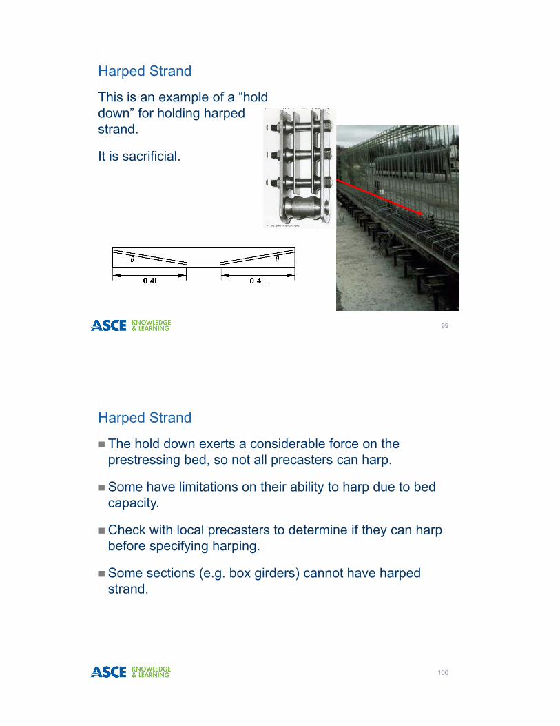
This is an example of a “hold down” for holding harped strand.
It is sacrificial.
Harped Strand
99
� The hold down exerts a considerable force on the prestressing bed, so not all precasters can harp.
�Some have limitations on their ability to harp due to bed capacity.
�Check with local precasters to determine if they can harp before specifying harping.
�Some sections (e.g. box girders) cannot have harped strand.
Harped Strand
100

To illustrate the use of harped strand, harp the two center strands 8 feet from the end.
Harped Strand
101
12”
10”
6”
2”2”
2” 4” 2”2”
7.33“
12”
10”
6”
2”2”
2” 4” 2”2”
2.0“
2”
Pattern at end Pattern at mid-span
8 ft
Side view
The angle, θ, is found from trigonometry:
Θ tan 16in 96in⁄ 9.46°
The position of the harped strand at any point in the cross section can now be found.
Harped Strand
102
8 ft
16 in θ

� The harp point is usually 0.3ℓ and 0.5ℓ from the end.
� The position of the harp point is determined by trial and error.
� The number of harped strands is determined by trial and error.
�See the PCI Design Handbook for more information on harping strand.
Harped Strand
103
To illustrate this, consider a section 3 feet from the end of the beam.
The strand position, measured from the top, is found from:
2in 36in tan 9.46 8inches
Harped Strand
104
12”
10”
6”
2”2”
2” 4” 2”2”
4“
8”
Then centroid of the strand from the bottom is:
6in
The eccentricity, e, is now:
10in– 6in 4 inches below the centroid.
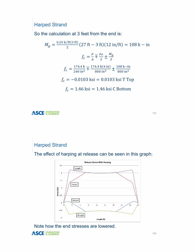
So the calculation at 3 feet from the end is:
. ⁄ 27ft 3ft 12in/ft 108k in
∓
.
∓ .
0.0103ksi 0.0103ksiTTop
1.46ksi 1.46ksiCBottom
Harped Strand
105
The effect of harping at release can be seen in this graph:
Harped Strand
106
Note how the end stresses are lowered.

However, while harping brings the end stress below the allowable, the top stress at midspan is still too high, so top steel would still be needed.
Harped Strand
107
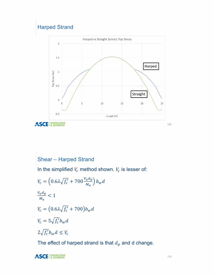
Harping is used to limit end stresses at release. However, harping also affects service level stresses which must be checked.
Harped Strand
108
Harped Strand
109
In the simplified method shown. is lesser of:
0.6 700
1
0.6 700
5
2
The effect of harped strand is that and d change.
Shear – Harped Strand
110

As an example, calculate at 2 foot from the support. Since the beam overhangs the support by 1 foot, this point is 3 feet from the end of beam.
This is the same point considered at release.
Shear – Harped Strand
111
12”
10”
6”
2”2”
2” 4” 2”2”
4“
8”
Note that now 14 inches; but 16 inches since d is not taken less than 0.8h 0.8 20in 16in.
0.6 1 5,000psi 700 .
12in 16in
79.7
0.53 1OK
. , . ,
154k 79.7OK
5 67.9k 79.7k use 0.75 67.9k50.9k
2 29.4 67.9kOK
Shear
112
At this point:778k in29.8k
concur. ⁄ 29.6k
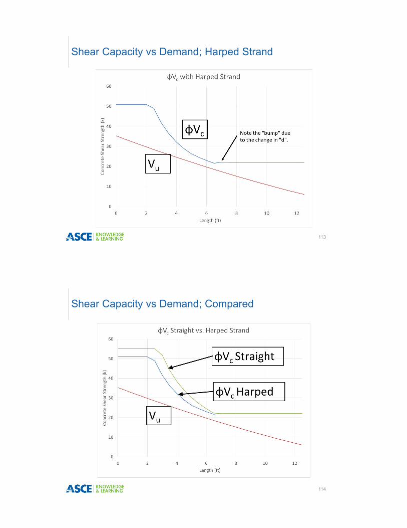
Shear Capacity vs Demand; Harped Strand
113
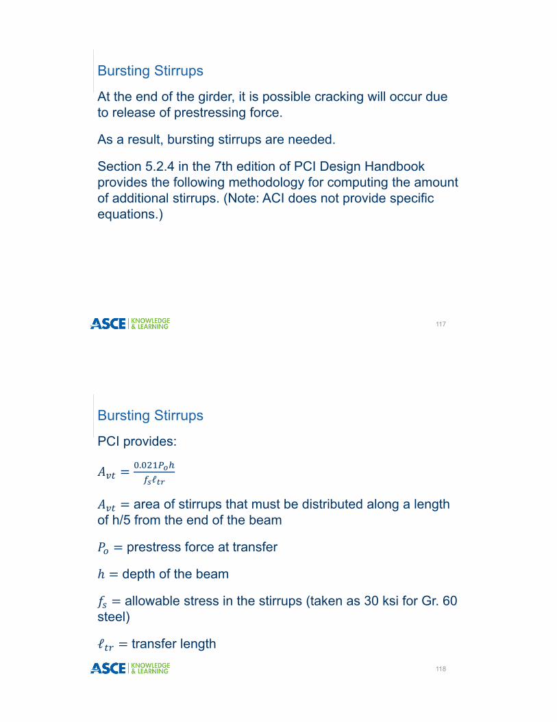
Shear Capacity vs Demand; Compared
114

The effect of harping strand is that d and become smaller so the shear strength in the simplified equation is lower.
Additional stirrups will usually take care of this.
As an alternative, using and may sometimes provide higher capacities (and sometimes not).
Harped Strand – and
115
�Harped strand affects as follows:� The term changes.�Stress changes.
�Harped strand affects as follows:� The term changes.�Stress changes.� There is now a term. In the example:
2strand 0.153in 164ksi sin 9.46 8.2k
Harped Strand – and
116
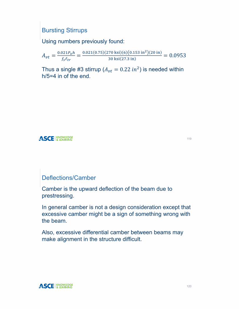
At the end of the girder, it is possible cracking will occur due to release of prestressing force.
As a result, bursting stirrups are needed.
Section 5.2.4 in the 7th edition of PCI Design Handbook provides the following methodology for computing the amount of additional stirrups. (Note: ACI does not provide specific equations.)
Bursting Stirrups
117
PCI provides:
.ℓ
area of stirrups that must be distributed along a length of h/5 from the end of the beam
prestress force at transfer
depth of the beam
allowable stress in the stirrups (taken as 30 ksi for Gr. 60 steel)
ℓ transfer length
Bursting Stirrups
118
Using numbers previously found:
.ℓ
. . . .
0.0953
Thus a single #3 stirrup ( 0.22 ) is needed within h/5=4 in of the end.
Bursting Stirrups
119
Camber is the upward deflection of the beam due to prestressing.
In general camber is not a design consideration except that excessive camber might be a sign of something wrong with the beam.
Also, excessive differential camber between beams may make alignment in the structure difficult.
Deflections/Camber
120

Initially, camber is caused by the effects of prestressing forces.
Over time, the prestressing forces cause creep in the beam and the beam both shortens and cambers up. Shrinkage also causes shortening and may increase or decrease camber depending on the shape and shrinkage of the beam.
This additional camber due to creep and shrinkage is called “Growth in Storage.”
Deflections/Camber
121
To get long term cambers, multiply the short term camber/deflection by these values (Table 5.8.2, PCI Design Handbook, 7th ed. These values are used for bridges AASHTO C5.7.3.6.2).
Camber/Deflection
122
Table 5.8.2 Suggested simple span multipliers to be used as a guide in estimating long-term cambers and deflections for typical prestressed components
Without composite topping
With composite topping
At erection:
1. Deflection (downward) component – apply to the elastic deflection due to the component weight at release of prestress 1.85 1.85
2. Camber (upward) component – apply to the elastic camber due to prestress at the time of release of prestress 1.80 1.80
Final:
3. Deflection (downward) – apply to the elastic camber due to prestress at the time of release of prestress 2.70 2.40
4. Camber (upward) component – apply to the elastic camber due to prestress at the time of release of prestress 2.45 2.20
5. Deflection (downward) – apply to elastic deflection due to superimposed dead load only 3.00 3.00
6. Deflection (downward) – apply to elastic deflection caused by the composite topping - 2.30
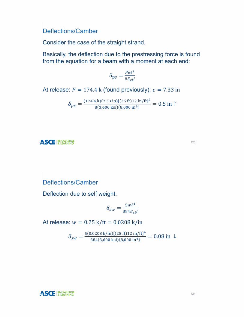
Consider the case of the straight strand.
Basically, the deflection due to the prestressing force is found from the equation for a beam with a moment at each end:
ℓ
At release: 174.4k (found previously); 7.33in
. . /, ,
0.5in ↑
Deflections/Camber
123
Deflection due to self weight:
ℓ
At release: 0.25k/ft 0.0208k/in
. / /, ,
0.08in ↓
Deflections/Camber
124
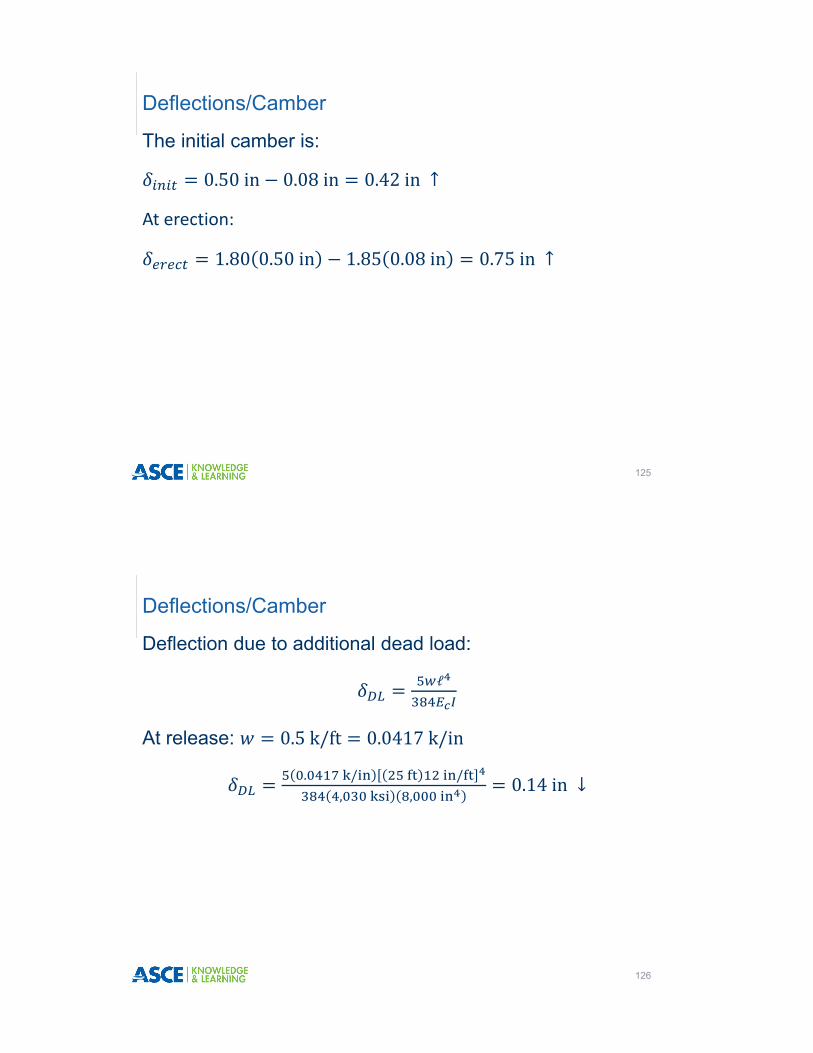
The initial camber is:
0.50in 0.08in 0.42in ↑
At erection:
1.80 0.50in 1.85 0.08in 0.75in ↑
Deflections/Camber
125
Deflection due to additional dead load:
ℓ
At release: 0.5k/ft 0.0417k/in
. / /, ,
0.14in ↓
Deflections/Camber
126

Long term camber:
2.45 0.5in – 2.7 0.08in 3.0 0.14in
0.59in ↑
Deflections/Camber
127
For other cases, such as harped strand, the PCI Design Handbook and PCI Bridge Design Handbook, have other formulae. For example, for a beam with both straight and harped strand, camber is:
Deflections/Camber
128
net ec.g.
e' ec
a a
∆
See the appendices of the PCI Design Handbook and PCI Bridge Design Handbook for more formulae.