SE-703 MANUAL EARTH-LEAKAGE MONITOR - …/media/files/littelfuse/technical...Page ii SE-703...
22
Tel: +1-800-832-3873 E-mail: [email protected] www.littelfuse.com/SE-703 SE-703 MANUAL EARTH-LEAKAGE MONITOR REVISION 12-B-092117 Copyright © 2017 by Littelfuse Startco All rights reserved. Document Number: PM-1045-EN Printed in Canada.
Transcript of SE-703 MANUAL EARTH-LEAKAGE MONITOR - …/media/files/littelfuse/technical...Page ii SE-703...

Tel: +1-800-832-3873 E-mail: [email protected]
www.littelfuse.com/SE-703
SE-703 MANUAL EARTH-LEAKAGE MONITOR
REVISION 12-B-092117
Copyright © 2017 by Littelfuse Startco All rights reserved.
Document Number: PM-1045-EN Printed in Canada.

Page i SE-703 Earth-Leakage Monitor Rev. 12-B-092117
This page intentionally left blank.
Page ii SE-703 Earth-Leakage Monitor Rev. 12-B-092117
TABLE OF CONTENTS SECTION PAGE
1 General ...................................................................... 1 2 Operation .................................................................. 1
2.1 Configuration-Switch Settings .................................. 1 2.1.1 Relay Operating Mode ................................... 1 2.1.2 Filter Selection ............................................... 1
2.2 Front-Panel Controls .................................................. 1 2.2.1 Earth-Leakage Trip Level .............................. 1 2.2.2 Earth-Leakage Trip Time .............................. 1 2.2.3 Reset ............................................................... 1 2.2.4 Test ................................................................. 1
2.3 Front-Panel Indication ............................................... 1 2.3.1 Power .............................................................. 1 2.3.2 Trip ................................................................. 1 2.3.3 CT Verification .............................................. 1
2.4 Analog Output ............................................................ 5 2.5 Self Diagnostics ......................................................... 5
3 Installation ................................................................ 5 4 Technical Specifications ........................................ 13 5 Ordering Information ........................................... 15 6 Warranty ................................................................. 15 7 Earth-Fault Performance Test ............................. 15 Appendix A SE-703 Revision History ........................ 17
LIST OF FIGURES FIGURE PAGE
1A SE-703-0X-00 Outline and Mounting Details .......... 2 1B SE-703-0X-02 Outline and Mounting Details .......... 3 1C SE-703-0X Outline and Mounting Details ............... 4 2 Typical Connection Diagrams ................................... 5 3 Typical Three-Phase Starter Connection .................. 6 4 EFCT-1 Outline and Mounting Details ..................... 7 5 EFCT-2 Outline and Mounting Details ..................... 8 6 EFCT-26 Outline and Mounting Details ................... 9 7 PMA-55 Panel-Mount Adapter ............................... 10 8 PMA-60 Panel-Mount Adapter ............................... 11 9 PGA-0500 Analog Percent Current Meter .............. 12 10 TRIP Relays Maximum Switching Capacity .......... 12 11 Earth-Fault-Test Circuit ........................................... 16
LIST OF TABLES TABLE PAGE
1 Earth-Fault-Test Record .......................................... 16
DISCLAIMER Specifications are subject to change without notice. Littelfuse Startco is not liable for contingent or consequential damages, or for expenses sustained as a result of incorrect application, incorrect adjustment, or a malfunction.

Page iii SE-703 Earth-Leakage Monitor Rev. 12-B-092117
This page intentionally left blank

Page 1 SE-703 Earth-Leakage Monitor Rev. 12-B-092117
1. GENERAL
The SE-703 is a microprocessor-based earth-leakagemonitor for ac power supply systems incorporating earth-fault current limitation. The SE-703 has two isolated Form-C relays for use in independent control circuits. Additional features include LED trip and power indication, latching trips with front-panel and remote reset, trip memory, test button, self diagnostics, 0 to 5-V analog output, CT verification with LED indication, digital selector switches, and switch-selectable algorithms for fixed-frequency or variable-frequency applications. Earth-leakage current is sensed by an EFCT-series core-balance earth-fault current transformer (CT). The trip level of the earth-leakage circuit is digital-switch selectable from 25 to 500 mA. Trip time is digital-switch selectable from INST (instantaneous) to 500 ms. Ordering option SE-703-0x-00 is AS/NZS 2081:2011 compliant. Its output relays operate in the fail-safe mode for undervoltage applications. Ordering option SE-703-0x-02 is AS/NZS 2081:2002 compliant. Its output relays operate in the fail-safe or non-fail-safe mode for undervoltage or shunt-trip applications.
2. OPERATION2.1 CONFIGURATION-SWITCH SETTINGS
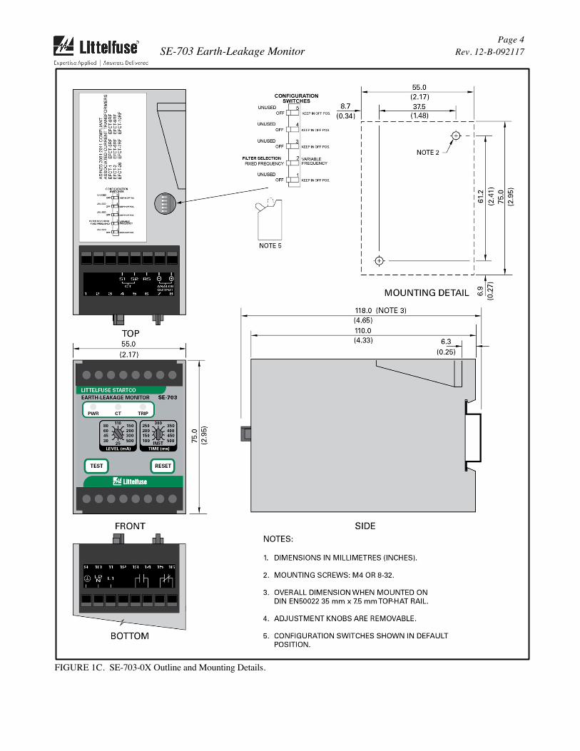
See Figs. 1A, 1B and 1C.
2.1.1 RELAY OPERATING MODE The output relays for ordering option SE-703-0x-00 operate only in the fail-safe mode for undervoltage applications. The output relays for ordering option SE-703-0x-02 operate in the fail-safe or non-fail-safe mode for undervoltage or shunt-trip applications. Switch 1 is used to set the operating mode of the output relays (for SE-703-0x-02 only).
In the fail-safe mode, the output relays energize when the earth-leakage circuit is not tripped. Non-volatile memory retains the trip status of the SE-703. If tripped, and the supply voltage is cycled, the SE-703 will remain tripped, with the trip relay de-energized and the TRIP LED on, until reset.
In the non-fail-safe mode, the output relays energize when a ground-fault trip occurs. Trip status is not retained in non-volatile memory.
2.1.2 FILTER SELECTION Switch 2 is used to select the filtering algorithm for a fixed-frequency (50/60 Hz) or variable-frequency application. The FIXED FREQUENCY setting uses a DFT filter that allows lower trip levels to be used by rejecting harmonics that can cause nuisance tripping. The VARIABLE FREQUENCY setting uses a peak-detection algorithm with a wider bandwidth for fault detection in variable-frequency drive applications.
2.2 FRONT-PANEL CONTROLS 2.2.1 EARTH-LEAKAGE TRIP LEVEL The LEVEL (mA) selector switch is used to set the earth-leakage trip level. For earth-leakage detection, the earth-leakage trip level must be substantially below the prospective earth-fault current. To avoid sympathetic tripping, the trip level must be above the charging current of the protected feeder.
2.2.2 EARTH-LEAKAGE TRIP TIME The SE-703 has a definite-time trip characteristic. The TIME (ms) selector switch is used to set the earth-leakage trip time for coordination with upstream and downstream earth-fault devices. Coordination requires the same trip level for all earth-leakage devices in a system and the trip time to progressively increase upstream. The amount of equipment removed from the system will be a minimum if the first earth-leakage device to operate is the one immediately upstream from the fault.
2.2.3 RESET A trip remains latched until the RESET button is pressed or the remote-reset terminals (6 and 7) are momentarily connected. The reset circuit responds only to a momentary closure so that a jammed or shorted button will not prevent a trip. The front-panel RESET button is inoperative when the remote-reset terminals are connected.
2.2.4 TEST The TEST button is used to test the earth-leakage circuit, the indication, and the output relays. When the TEST button is pressed for one second, a test signal is applied to the earth-leakage-detection circuit, the circuit will trip, the TRIP LED will light, and the output relays will operate.
2.3 FRONT-PANEL INDICATION 2.3.1 POWER The green LED labelled PWR indicates presence of supply voltage.
2.3.2 TRIP The red LED labelled TRIP indicates a trip. A solid red LED indicates an earth-leakage trip and a flashing LED indicates a trip initiated by a CT fault. Two fast flashes of the TRIP LED indicate a diagnostic trip. See Section 2.5.
2.3.3 CT VERIFICATION The green LED labelled CT indicates that an EFCT-series sensor is connected.

Page 2 SE-703 Earth-Leakage Monitor Rev. 12-B-092117
FIGURE 1A. SE-703-0X-00 Outline and Mounting Details.

Page 3 SE-703 Earth-Leakage Monitor Rev. 12-B-092117
FIGURE 1B. SE-703-0X-02 Outline and Mounting Details.
Page 4 SE-703 Earth-Leakage Monitor Rev. 12-B-092117
FIGURE 1C. SE-703-0X Outline and Mounting Details.
Page 5 SE-703 Earth-Leakage Monitor Rev. 12-B-092117
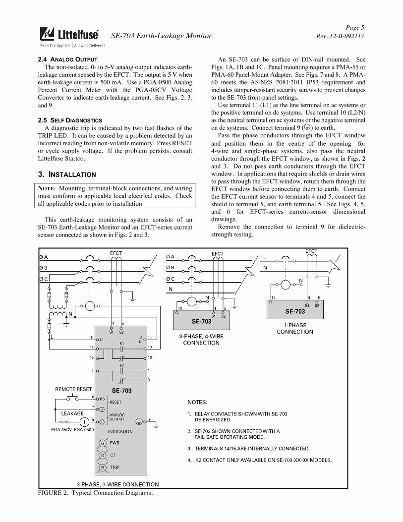
2.4 ANALOG OUTPUT The non-isolated, 0- to 5-V analog output indicates earth-leakage current sensed by the EFCT. The output is 5 V when earth-leakage current is 500 mA. Use a PGA-0500 Analog Percent Current Meter with the PGA-05CV Voltage Converter to indicate earth-leakage current. See Figs. 2, 3, and 9.
2.5 SELF DIAGNOSTICS A diagnostic trip is indicated by two fast flashes of the TRIP LED. It can be caused by a problem detected by an incorrect reading from non-volatile memory. Press RESET or cycle supply voltage. If the problem persists, consult Littelfuse Startco.
3. INSTALLATION
NOTE: Mounting, terminal-block connections, and wiring must conform to applicable local electrical codes. Check all applicable codes prior to installation
This earth-leakage monitoring system consists of an SE-703 Earth-Leakage Monitor and an EFCT-series current sensor connected as shown in Figs. 2 and 3.
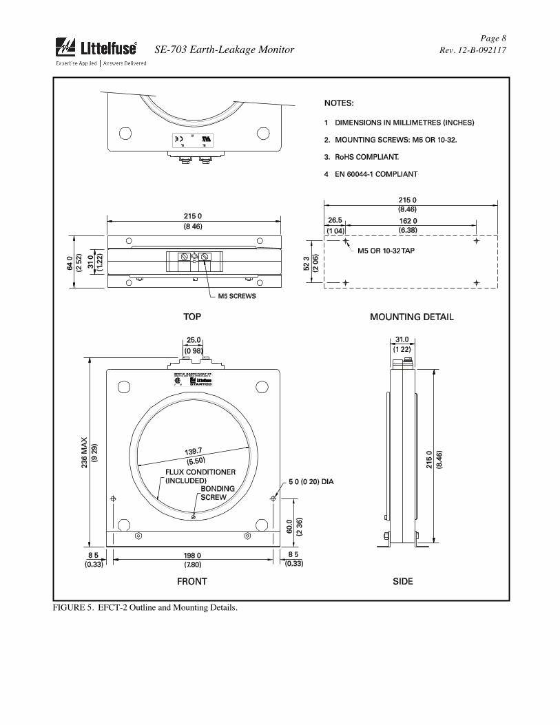
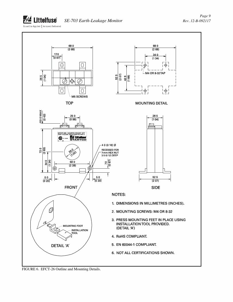
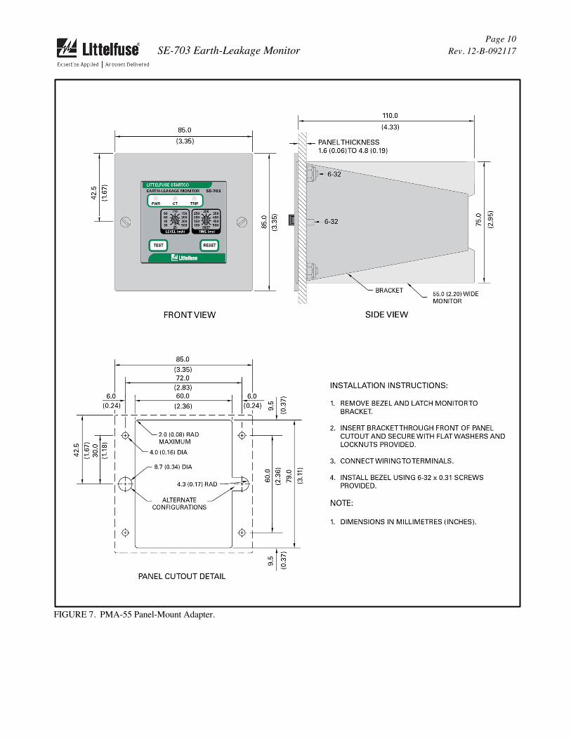
An SE-703 can be surface or DIN-rail mounted. See Figs. 1A, 1B and 1C. Panel mounting requires a PMA-55 or PMA-60 Panel-Mount Adapter. See Figs. 7 and 8. A PMA-60 meets the AS/NZS 2081:2011 IP53 requirement and includes tamper-resistant security screws to prevent changes to the SE-703 front-panel settings. Use terminal 11 (L1) as the line terminal on ac systems or the positive terminal on dc systems. Use terminal 10 (L2/N) as the neutral terminal on ac systems or the negative terminal on dc systems. Connect terminal 9 ( ) to earth. Pass the phase conductors through the EFCT window and position them in the centre of the opening¾for 4-wire and single-phase systems, also pass the neutralconductor through the EFCT window, as shown in Figs. 2and 3. Do not pass earth conductors through the EFCTwindow. In applications that require shields or drain wiresto pass through the EFCT window, return them through theEFCT window before connecting them to earth. Connectthe EFCT current sensor to terminals 4 and 5, connect theshield to terminal 5, and earth terminal 5. See Figs. 4, 5,and 6 for EFCT-series current-sensor dimensionaldrawings.
Remove the connection to terminal 9 for dielectric-strength testing.
FIGURE 2. Typical Connection Diagrams.

Page 6 SE-703 Earth-Leakage Monitor Rev. 12-B-092117
FIGURE 3. Typical Three-Phase Starter Connection.

SE-703 Earth-Leakage Monitor Page 7
Rev. 12-B-092117
FIGURE 4. EFCT-1 Outline and Mounting Details.
SE-703 Earth-Leakage Monitor Page 8
Rev. 12-B-092117
FIGURE 5. EFCT-2 Outline and Mounting Details.
SE-703 Earth-Leakage Monitor Page 9
Rev. 12-B-092117
FIGURE 6. EFCT-26 Outline and Mounting Details.
SE-703 Earth-Leakage Monitor Page 10
Rev. 12-B-092117
FIGURE 7. PMA-55 Panel-Mount Adapter.

SE-703 Earth-Leakage Monitor Page 11
Rev. 12-B-092117
FIGURE 8. PMA-60 Panel-Mount Adapter.
SE-703 Earth-Leakage Monitor Page 12
Rev. 12-B-092117
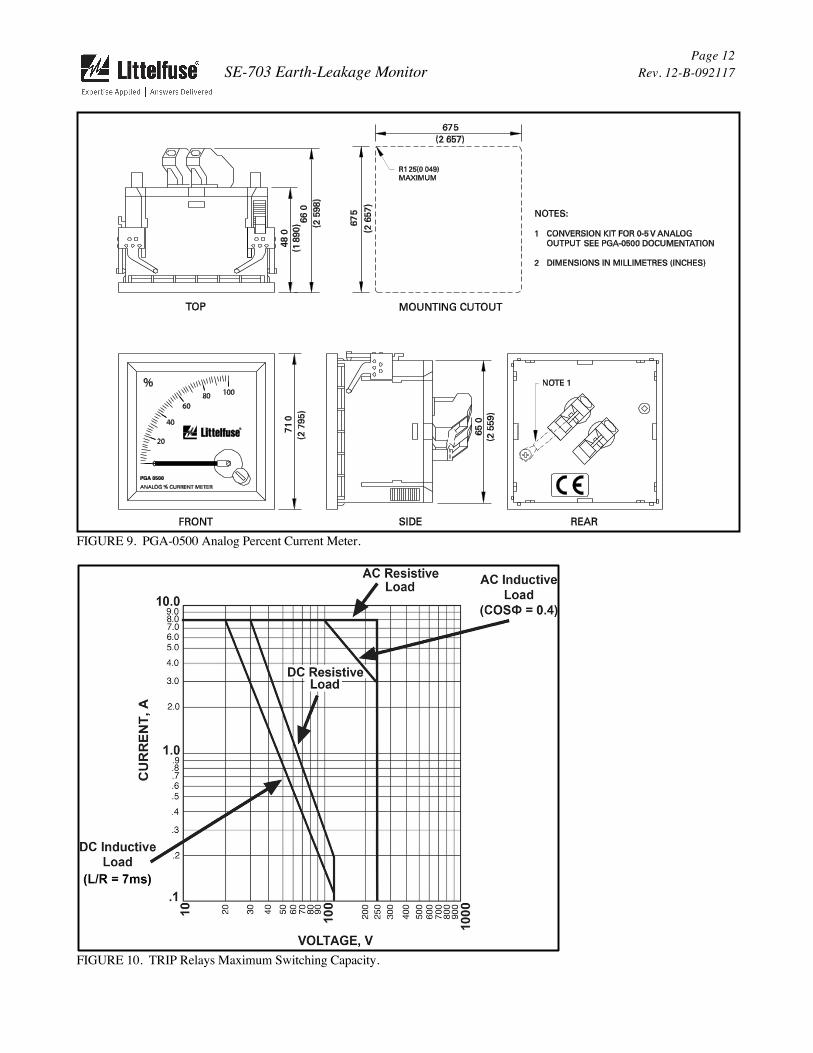
FIGURE 9. PGA-0500 Analog Percent Current Meter.
FIGURE 10. TRIP Relays Maximum Switching Capacity.
SE-703 Earth-Leakage Monitor Page 13
Rev. 12-B-092117
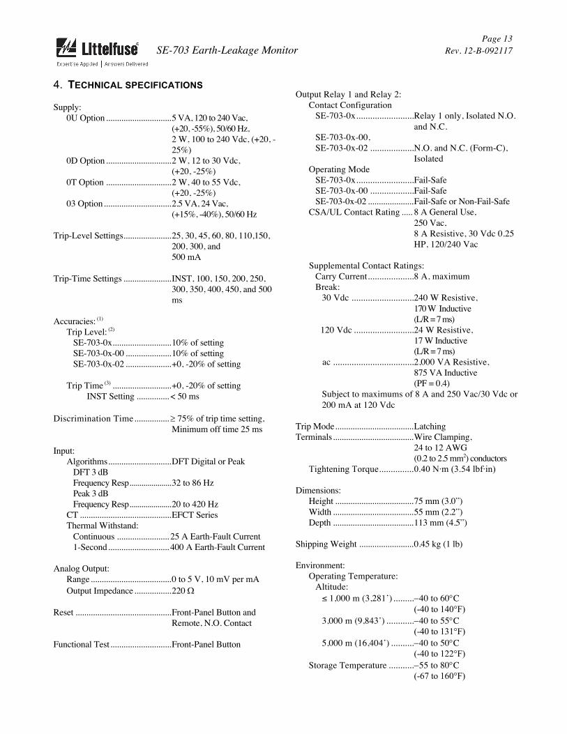
4. TECHNICAL SPECIFICATIONS
Supply: 0U Option .............................. 5 VA, 120 to 240 Vac,
(+20, -55%), 50/60 Hz, 2 W, 100 to 240 Vdc, (+20, -25%)
0D Option .............................. 2 W, 12 to 30 Vdc, (+20, -25%)
0T Option .............................. 2 W, 40 to 55 Vdc, (+20, -25%)
03 Option ............................... 2.5 VA, 24 Vac, (+15%, -40%), 50/60 Hz
Trip-Level Settings ...................... 25, 30, 45, 60, 80, 110, 150, 200, 300, and 500 mA
Trip-Time Settings ...................... INST, 100, 150, 200, 250, 300, 350, 400, 450, and 500 ms
Accuracies: (1) Trip Level: (2)
SE-703-0x ........................... 10% of setting
SE-703-0x-00 ..................... 10% of setting SE-703-0x-02 ..................... +0, -20% of setting
Trip Time (3) ........................... +0, -20% of setting INST Setting ............... < 50 ms
Discrimination Time ................ ³ 75% of trip time setting, Minimum off time 25 ms
Input: Algorithms ............................. DFT Digital or Peak
DFT 3 dB Frequency Resp ..................... 32 to 86 Hz Peak 3 dB Frequency Resp ..................... 20 to 420 Hz
CT .......................................... EFCT Series Thermal Withstand:
Continuous ........................ 25 A Earth-Fault Current 1-Second ............................ 400 A Earth-Fault Current
Analog Output: Range ..................................... 0 to 5 V, 10 mV per mA Output Impedance ................. 220 W
Reset ............................................ Front-Panel Button and Remote, N.O. Contact
Functional Test ............................ Front-Panel Button
Output Relay 1 and Relay 2: Contact Configuration
SE-703-0x ......................... Relay 1 only, Isolated N.O. and N.C.
SE-703-0x-00, SE-703-0x-02 ................... N.O. and N.C. (Form-C),
Isolated Operating Mode
SE-703-0x ......................... Fail-Safe SE-703-0x-00 ................... Fail-Safe SE-703-0x-02 ..................... Fail-Safe or Non-Fail-Safe
CSA/UL Contact Rating ..... 8 A General Use, 250 Vac, 8 A Resistive, 30 Vdc 0.25 HP, 120/240 Vac
Supplemental Contact Ratings: Carry Current .................... 8 A, maximum Break:
30 Vdc ........................... 240 W Resistive, 170 W Inductive (L/R = 7 ms)
120 Vdc .......................... 24 W Resistive, 17 W Inductive (L/R = 7 ms)
ac ................................... 2,000 VA Resistive, 875 VA Inductive (PF = 0.4)
Subject to maximums of 8 A and 250 Vac/30 Vdc or 200 mA at 120 Vdc
Trip Mode .................................... Latching Terminals ..................................... Wire Clamping,
24 to 12 AWG (0.2 to 2.5 mm2) conductors
Tightening Torque ............... 0.40 N·m (3.54 lbf·in)
Dimensions: Height .................................... 75 mm (3.0”) Width ..................................... 55 mm (2.2”) Depth ..................................... 113 mm (4.5”)
Shipping Weight ......................... 0.45 kg (1 lb)
Environment: Operating Temperature:
Altitude: ≤ 1,000 m (3,281’) ......... -40 to 60°C
(-40 to 140°F)3,000 m (9,843’) ............ -40 to 55°C
(-40 to 131°F) 5,000 m (16,404’) .......... -40 to 50°C
(-40 to 122°F)Storage Temperature ........... -55 to 80°C
(-67 to 160°F)
SE-703 Earth-Leakage Monitor Page 14
Rev. 12-B-092117
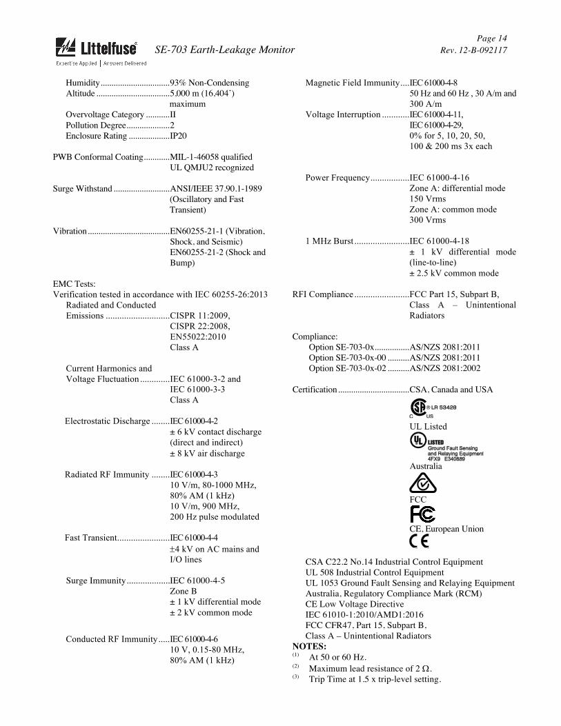
Humidity ................................ 93% Non-Condensing Altitude .................................. 5,000 m (16,404’)
maximum Overvoltage Category ........... II Pollution Degree .................... 2 Enclosure Rating ................... IP20
PWB Conformal Coating ............ MIL-1-46058 qualified UL QMJU2 recognized
Surge Withstand .......................... ANSI/IEEE 37.90.1-1989 (Oscillatory and Fast Transient)
Vibration ...................................... EN60255-21-1 (Vibration, Shock, and Seismic) EN60255-21-2 (Shock and Bump)
EMC Tests: Verification tested in accordance with IEC 60255-26:2013
Radiated and Conducted Emissions ............................ CISPR 11:2009,
CISPR 22:2008, EN55022:2010 Class A
Current Harmonics and Voltage Fluctuation ............. IEC 61000-3-2 and
IEC 61000-3-3 Class A
Electrostatic Discharge ........ IEC 61000-4-2 ± 6 kV contact discharge (direct and indirect)± 8 kV air discharge
Radiated RF Immunity ........ IEC 61000-4-3 10 V/m, 80-1000 MHz, 80% AM (1 kHz) 10 V/m, 900 MHz, 200 Hz pulse modulated
Fast Transient ....................... IEC 61000-4-4 ±4 kV on AC mains and I/O lines
Surge Immunity ................... IEC 61000-4-5 Zone B ± 1 kV differential mode ± 2 kV common mode
Conducted RF Immunity ..... IEC 61000-4-6 10 V, 0.15-80 MHz, 80% AM (1 kHz)
Magnetic Field Immunity .... IEC 61000-4-8 50 Hz and 60 Hz , 30 A/m and 300 A/m
Voltage Interruption ............ IEC 61000-4-11, IEC 61000-4-29, 0% for 5, 10, 20, 50, 100 & 200 ms 3x each
Power Frequency ................. IEC 61000-4-16 Zone A: differential mode 150 Vrms Zone A: common mode 300 Vrms
1 MHz Burst ........................ IEC 61000-4-18 ± 1 kV differential mode (line-to-line) ± 2.5 kV common mode
RFI Compliance ........................ FCC Part 15, Subpart B, Class A – Unintentional Radiators
Compliance: Option SE-703-0x ................ AS/NZS 2081:2011 Option SE-703-0x-00 .......... AS/NZS 2081:2011 Option SE-703-0x-02 .......... AS/NZS 2081:2002
Certification ................................. CSA, Canada and USA
UL Listed
Australia
FCC
CE, European Union
CSA C22.2 No.14 Industrial Control Equipment UL 508 Industrial Control Equipment UL 1053 Ground Fault Sensing and Relaying Equipment Australia, Regulatory Compliance Mark (RCM) CE Low Voltage Directive IEC 61010-1:2010/AMD1:2016 FCC CFR47, Part 15, Subpart B, Class A – Unintentional Radiators
NOTES: (1) At 50 or 60 Hz.(2) Maximum lead resistance of 2 W.(3) Trip Time at 1.5 x trip-level setting.
SE-703 Earth-Leakage Monitor Page 15
Rev. 12-B-092117
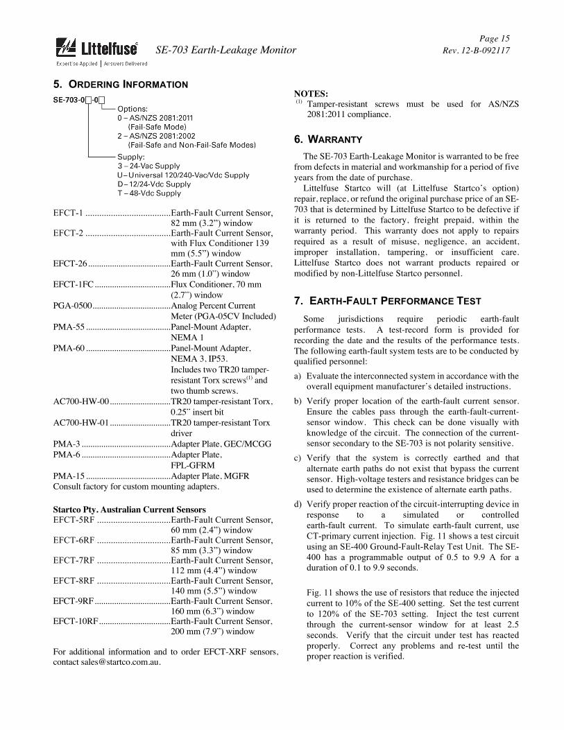
5. ORDERING INFORMATION
EFCT-1 ..................................... Earth-Fault Current Sensor, 82 mm (3.2”) window
EFCT-2 ..................................... Earth-Fault Current Sensor, with Flux Conditioner 139 mm (5.5”) window
EFCT-26 ...................................... Earth-Fault Current Sensor, 26 mm (1.0”) window
EFCT-1FC ................................... Flux Conditioner, 70 mm (2.7”) window
PGA-0500 .................................... Analog Percent Current Meter (PGA-05CV Included)
PMA-55 ....................................... Panel-Mount Adapter, NEMA 1
PMA-60 ....................................... Panel-Mount Adapter, NEMA 3, IP53. Includes two TR20 tamper-resistant Torx screws(1) and two thumb screws.
AC700-HW-00 ............................ TR20 tamper-resistant Torx, 0.25” insert bit
AC700-HW-01 ............................ TR20 tamper-resistant Torx driver
PMA-3 ......................................... Adapter Plate, GEC/MCGG PMA-6 ......................................... Adapter Plate,
FPL-GFRM PMA-15 ....................................... Adapter Plate, MGFR Consult factory for custom mounting adapters.
Startco Pty. Australian Current Sensors EFCT-5RF ................................ Earth-Fault Current Sensor,
60 mm (2.4”) window EFCT-6RF ................................ Earth-Fault Current Sensor,
85 mm (3.3”) window EFCT-7RF ................................ Earth-Fault Current Sensor,
112 mm (4.4”) window EFCT-8RF ................................ Earth-Fault Current Sensor,
140 mm (5.5”) window EFCT-9RF ................................... Earth-Fault Current Sensor,
160 mm (6.3”) window EFCT-10RF ................................. Earth-Fault Current Sensor,
200 mm (7.9”) window
For additional information and to order EFCT-XRF sensors, contact [email protected].
NOTES: (1) Tamper-resistant screws must be used for AS/NZS
2081:2011 compliance.
6. WARRANTYThe SE-703 Earth-Leakage Monitor is warranted to be free
from defects in material and workmanship for a period of five years from the date of purchase. Littelfuse Startco will (at Littelfuse Startco’s option) repair, replace, or refund the original purchase price of an SE-703 that is determined by Littelfuse Startco to be defective if it is returned to the factory, freight prepaid, within the warranty period. This warranty does not apply to repairs required as a result of misuse, negligence, an accident, improper installation, tampering, or insufficient care. Littelfuse Startco does not warrant products repaired or modified by non-Littelfuse Startco personnel.
7. EARTH-FAULT PERFORMANCE TEST
Some jurisdictions require periodic earth-fault performance tests. A test-record form is provided for recording the date and the results of the performance tests. The following earth-fault system tests are to be conducted by qualified personnel: a) Evaluate the interconnected system in accordance with the
overall equipment manufacturer’s detailed instructions.b) Verify proper location of the earth-fault current sensor.
Ensure the cables pass through the earth-fault-current-sensor window. This check can be done visually withknowledge of the circuit. The connection of the current-sensor secondary to the SE-703 is not polarity sensitive.
c) Verify that the system is correctly earthed and thatalternate earth paths do not exist that bypass the currentsensor. High-voltage testers and resistance bridges can beused to determine the existence of alternate earth paths.
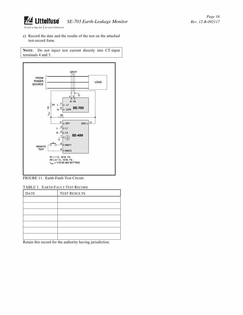
d) Verify proper reaction of the circuit-interrupting device inresponse to a simulated or controlledearth-fault current. To simulate earth-fault current, useCT-primary current injection. Fig. 11 shows a test circuitusing an SE-400 Ground-Fault-Relay Test Unit. The SE-400 has a programmable output of 0.5 to 9.9 A for aduration of 0.1 to 9.9 seconds.
Fig. 11 shows the use of resistors that reduce the injectedcurrent to 10% of the SE-400 setting. Set the test currentto 120% of the SE-703 setting. Inject the test currentthrough the current-sensor window for at least 2.5seconds. Verify that the circuit under test has reactedproperly. Correct any problems and re-test until theproper reaction is verified.
SE-703 Earth-Leakage Monitor Page 16
Rev. 12-B-092117
e) Record the date and the results of the test on the attachedtest-record form.
NOTE: Do not inject test current directly into CT-input terminals 4 and 5.
FIGURE 11. Earth-Fault-Test Circuit.
TABLE 1. EARTH-FAULT-TEST RECORD
DATE TEST RESULTS
Retain this record for the authority having jurisdiction.

SE-703 Earth-Leakage Monitor Page 17
Rev. 12-B-092117
APPENDIX A SE-703 REVISION HISTORY
MANUAL RELEASE DATE
MANUAL REVISION
PRODUCT REVISION (REVISION NUMBER ON PRODUCT LABEL)
September 21, 2017 12-B-09211708
March 10, 2017 12-A-031017
March 10, 2016 11-C-031016
07 August 28, 2014 11-B-082814
April 21, 2014 11-A-042114
April 23, 2013 10-A-042313 06
MANUAL REVISION HISTORY REVISION 12-B-092117 SECTION 4 SECTION 5
Updated certification information. REVISION 12-A-031017
SECTION 2 Added Figs. 1A, 1B and 1C.
SECTION 3 Updated Figs. 2 and 3.
Added Fig. 10. SECTION 4
Added ordering option details. SECTION 5
Added ordering options. SECTION 7
Added Fig. 11. REVISION 11-C-031016
SECTION 5 Terminal torque specification added. RCM certification added.
REVISION 11-B-082814 SECTION 3
EFCT-x figures updated. SECTION 4
EMC Test specifications updated. REVISION 11-A-042114
AS/NZS 2081:2011 compliance added. Section 4 removed.
SECTION 3 Figs. 2, 3, 4, 5, 6, and 9 updated.
SECTION 4 Update to include altitude and vibration specifications. FCC certification added.
SECTION 5 Ordering information updated.
SECTION 7 Fig. 10 updated.
REVISION 10-A-042313 SECTION 3
Figs. 2 and 3 updated to include PGA-05CV. SECTION 5
SE-703 Earth-Leakage Monitor Page 18
Rev. 12-B-092117
Environment section updated to include Fahrenheit temperature range. APPENDIX A
Revision history added.
PRODUCT REVISION HISTORY REVISION 08
Firmware: Trip levels updated for compliance with AS/NZS 2081:2011 (ordering option SE-703-0x-00) and AS/NZS 2081:2002 (ordering option SE-703-0x-02).
Hardware: Added two Form-C relays. RoHS2 compliance. REVISION 07
Firmware: Trip levels updated for compliance with AS/NZS 2081:2011. Hardware: Full conformal coating on all PCB’s.
REVISION 06 Firmware: Improved operation of front-panel test button.