SDP:01 - Scaniatis.scania.com/site/helpfiles/sdp01en-GB19.pdf · Scania CV AB 2014, Sweden SDP:01...
100
© Scania CV AB 2014, Sweden SDP:01 Issue 19 en-GB Scania Diagnos & Programmer 3 User instructions Applies from SDP3 2.18
Transcript of SDP:01 - Scaniatis.scania.com/site/helpfiles/sdp01en-GB19.pdf · Scania CV AB 2014, Sweden SDP:01...

© Scania CV AB 2014, Sweden
SDP:01Issue 19 en-GB
Scania Diagnos & Programmer 3User instructions
Applies from SDP3 2.18

© Scania CV AB 2014
Introduction .............................................................................................. 3General .......................................................................................................... 3
System requirements and ancillary equipment ......................... 4System requirements ..................................................................................... 4Ancillary equipment ...................................................................................... 4
Safety ....................................................................................................... 10Test driving the vehicle ............................................................................... 10Connecting and disconnecting .................................................................... 11Adjustment .................................................................................................. 11
Installation .............................................................................................. 12Installing the program ................................................................................. 12
Working with SDP3 ............................................................................. 14About the user instructions ......................................................................... 14Text display and searching in the text ......................................................... 15Starting a task .............................................................................................. 16Checks and adjustments .............................................................................. 17Conversion .................................................................................................. 54Inspection .................................................................................................... 63ECU update ................................................................................................. 64Bodywork .................................................................................................... 75Connecting .................................................................................................. 76Spare parts programming ............................................................................ 78Communication ........................................................................................... 79Graphic symbols in the program ................................................................. 80Demo mode ................................................................................................. 85Saving and printing vehicle information ..................................................... 87Remote Diagnostics .................................................................................... 89Operational data .......................................................................................... 91Find ............................................................................................................. 95Viewing all fault codes ............................................................................... 96Product update ............................................................................................. 98Help ............................................................................................................. 99
Fault handling ...................................................................................... 100Electromagnetic fields ............................................................................... 100SDP3 crashes under work in progress ....................................................... 100Rebooting a wizard that is stuck ............................................................... 100

SDP:01 Issue 19 © Scania CV AB 2014 3 (100)
Introduction
IntroductionGeneralScania Diagnos & Programmer 3 (SDP3) com-municates with Scania vehicles and Scania industrial and marine engines. The program has been developed to support the electrical system with CAN communication.
The program is used for troubleshooting, adjusting customer parameters, calibrations, conversions affecting the electrical system and updating software in control units.

4 (100) © Scania CV AB 2014 SDP:01 Issue 19
System requirements and ancillary equipment
System requirements and ancillary
equipmentSystem requirementsThe system requirements applicable to SDP3 can be found on the Technical Information Library website which can be accessed via SAIL.
Ancillary equipmentUse of the program requires a computer, a USB key and a VCI. These components must com-ply with the applicable system requirements, see System requirements, so that the program will operate correctly.
USB keyA USB key supplied by Scania is required. In accordance with the applicable agreements, the USB key is the property of Scania. This means that a stolen or lost USB key should be reported to Scania, where it is entered on a list of blocked IDs. To do this, contact your dis-tributor who will in turn contact Scania.
Distributors can find more information on USB keys in the VCI and USB procedures for exter-nal administration. This can be accessed via SAIL under the Services/Technical Informa-tion/VCI and USB keys tab.

SDP:01 Issue 19 © Scania CV AB 2014 5 (100)
System requirements and ancillary equipment
You will find information about the USB key that is used under Settings in the menu. The access levels for the different types of USB keys that may be used are also described here.
The USB key controls access, i.e. which parts of the program you have access rights to.
A different type of USB key is required depending on whether you will be working on a vehicle or an industrial and marine engine.
If access is shown as BLOCKED, this implies that Scania has entered the USB key in a list of blocked IDs. If access is shown as UNKNOWN, this indicates that the USB key is of a different type to the one approved by Sca-nia.
Information about the USB key that is currently in use can be obtained under Settings in the menu.

System requirements and ancillary equipment
6 (100) © Scania CV AB 2014 SDP:01 Issue 19
VCIVCI is the interface that is used between the vehicle or industrial and marine engine and the computer and can be purchased from Scania as a special tool, part number 99 430.
After connecting VCI to the computer and starting SDP3, you can access information about VCI by opening View in the menu.

SDP:01 Issue 19 © Scania CV AB 2014 7 (100)
System requirements and ancillary equipment
Function of the lamps
PWR (green) The lamp lights up continuously when the VCI is supplied with voltage both from the vehicle and the PC.
VCI2: The lamp flashes when the VCI2 is connected to the PC.
CAN (yellow) The light lights up (flashes rapidly) when data is transmitted between the VCI and the vehicle via the CAN bus.
Error (red) The lamp lights up when there is a communication error on the CAN bus.
VCI2: USB (yellow)
The lamp lights up (flashes rapidly) when data is transmitted between the PC and VCI via the USB key.
VCI3: Info (orange)
The lamp flashes rapidly when general information is sent between the computer and VCI3.
WLAN (blue) The lamp is on or flashes when VCI3 is connected to a local network via wireless connection in one of the following ways: The lamp is constantly on when it is connected to a computer via a wireless network with a good signal strength. The lamp flashes slowly and steadily when VCI3 does not have contact with the computer but is connected to a wireless network with a good signal strength. The lamp flashes constantly once every second. Something was wrong during start.

System requirements and ancillary equipment
8 (100) © Scania CV AB 2014 SDP:01 Issue 19
Adapter for connection to industrial and marine engines with diagnostic socketS6 or S8 for E2011 enginesOn industrial and marine engines with an S6 or S8 control unit on E2011 type engines, the diagnostic socket is located on the engine.
When connecting SDP3, an adapter must be used in order to connect VCI. The adapter can be ordered from Scania as a spare part, part number 1 862 924.
317
976
Adapter for connecting VCI. The location of the diagnostic socket on the engine may vary. The illustration is an example.

SDP:01 Issue 19 © Scania CV AB 2014 9 (100)
System requirements and ancillary equipment
Adapter for connection on industrial and marine engines without diagnostic socketS6 for P96 enginesAn adapter must be used when connecting SDP3 to the S6 engine control unit on indus-trial and marine engines without a diagnostic socket. The adapter can be purchased from Scania as a special tool, part number 99 043. The adapter is used together with VCI.
WARNING!Do not use adapter 99 043 on engines with S8 control units. The connection for engine diag-nostic information has been moved to cable harness B3.
1. Switch
2. Connector to engine control unit connec-tion B1
3. Connection for engine cable harness B1
4. Connection for VCI
5. Connection for VCI with 4 pin DIN
6. Connection for external 24 V power source
7. Cables for external power source
8. Lamps for battery voltage U30 (red) and for when the starter key is in drive position 15 (green)

Safety
10 (100) © Scania CV AB 2014 SDP:01 Issue 19
SafetyIMPORTANT!
Always ensure that a task is carried out so that there is no risk that you or anyone else will be injured.
Test driving the vehicleRemember that there are some risks if you carry out a test drive when the program is con-nected. Two persons are required to carry out a test drive: one to drive the vehicle, and one to operate the program. Scania strongly advises against test driving on public highways with the VCI or computer connected unless other-wise specified.
Vehicle components can be unexpectedly acti-vated or the engine can stop (causing the loss of power steering).

SDP:01 Issue 19 © Scania CV AB 2014 11 (100)
Safety
Connecting and disconnectingConnection or disconnection of the VCI or computer when the vehicle is moving is forbid-den. The vehicle must be stationary when the VCI or computer is connected or disconnected. Other instructions for use can be found in the program.
AdjustmentDuring adjustment, settings in the control units are changed. Some of these changes, or combi-nations of settings, may have an adverse effect on the characteristics of the vehicle/engine without prior warning. Incorrect use of the pro-gram therefore entails a risk of personal injury, damage to property and a breach of the relevant legislation. Adjustments should therefore only be carried out by personnel who are receiving ongoing training by the Scania organisation on SDP3 and the vehicles and industrial and marine engines concerned, and who are study-ing the SDP3 user instructions and other ser-vice instructions on an ongoing basis.
WARNING!Adjustment of parameters should only be car-ried out on stationary vehicles.

12 (100) © Scania CV AB 2014 SDP:01 Issue 19
Installation
InstallationNote:Before the program is distributed, it is virus-checked as comprehensively as possible. Make sure that the computer on which the program is installed is virus-free.
It is necessary to have administrator rights in order to install the SDP3 program.
Installing the programNote:The USB key and VCI must not be connected to the computer during the installation of SDP3, especially not if SDP3 is installed for the first time.
1. Close all active programs except Windows.
2. Regardless of whether the file was down-loaded from the internet or comes from a CD, proceed as follows:
3. Double-click the program file.
4. Installation starts and a number of dialogue boxes will be displayed. Follow the instruc-tions in these dialogue boxes.
Installing SDP3 may involve several installa-tions and it is only when all these have been carried out that you can use the program cor-rectly.

SDP:01 Issue 19 © Scania CV AB 2014 13 (100)
Installation
Clickable shortcutsClickable shortcuts located on the computer desktop after installation:
At installation time, two directories are created which you can also access via shortcuts on the desktop.
• Reports: Saved documents are stored here, e.g. printouts from work in SDP3.
• Log files: Information recorded while work-ing in SDP3 is logged here. This informa-tion may be useful for troubleshooting, for example. The logging level can be set in SDP3 Configurator.
Start SDP3.
Open SDP3 Configurator to change the lan-guage or the logging level.

14 (100) © Scania CV AB 2014 SDP:01 Issue 19
Working with SDP3
Working with SDP3About the user instructionsThis section describes how SDP3 works. Some parts are only suitable for working with a vehi-cle and a USB key with the highest access lev-els. This means that if you are working on an industrial and marine engine or have a USB key with limited access levels, not all the sec-tions described are available.
The user instructions take their examples from vehicles. For those sections that are accessible to industrial and marine engines, the instruc-tions still apply even though texts and illustra-tions are referring to vehicles.

SDP:01 Issue 19 © Scania CV AB 2014 15 (100)
Working with SDP3
Text display and searching in the textFor some texts it is possible to select how to display the text in SDP3.
At the bottom right of the page there is a zoom function.
It is also possible to select how the text layout should be displayed using three buttons.
There is a search function at the bottom left of the page. When you click the symbol a text box appears where you can enter the search word and search the text on the page.
320
386
Zoom function
Selecting the text layout
320
387
Search function

Working with SDP3
16 (100) © Scania CV AB 2014 SDP:01 Issue 19
Starting a taskWhen you have started the program, the start window will be displayed. Select here the type of task you wish to carry out: Checks and adjustments, Conversion, Maintenance, ECU update or Bodywork.
More information about the relevant work option can be found on the following pages.
Selecting the work option: Checks and adjust-ments, Conversion, Maintenance, ECU update or Bodywork.

SDP:01 Issue 19 © Scania CV AB 2014 17 (100)
Working with SDP3
Checks and adjustmentsIn the Checks and adjustments work option, you can carry out troubleshooting and change adjustable values.
Here you can access information in order to troubleshoot the different control systems and their related components and circuits. There is also an option to troubleshoot via user func-tions.
You can also reset parameters in the vehicle control units and carry out calibrations and resetting.
You can also analyse the vehicle's stored oper-ational data either directly in SDP3 or via the menu option View stored operational data. For more information, refer to section Operational data.
Procedure when checkingA suitable procedure for troubleshooting is described here.
Start by finding out what problems the cus-tomer has experienced.
1. Start SDP3.
2. Start the Checks and adjustments work option.
3. Go to Electrical system and read the regis-tered fault codes.
All registered fault codes will be displayed under Electrical system.
If there are fault codes connected with the problems which the customer has experienced, continue troubleshooting via Electrical system by checking the circuits concerned and rectify the fault. Otherwise, you should carry out trou-bleshooting via User functions. Start by check-ing that the vehicle has a user function which could be connected with the problem experi-enced by the customer. Then continue trouble-shooting using the information provided under User functions.

Working with SDP3
18 (100) © Scania CV AB 2014 SDP:01 Issue 19
Troubleshooting via Electrical systemUnder Electrical system, you can troubleshoot in relation to the electrical system. SDP3 com-municates with all the vehicle control units at the same time.
You can obtain a description of the electrical system with its related circuits and compo-nents. You can read fault codes, read signals, activate components and carry out tests, adjust-ments and calibrations.
Navigation under Electrical system
Navigation under the Electrical system has the same structure as the vehicle’s electrical sys-tem.
1. Vehicle2. ECU system: The vehicle has a number of
electronic control systems. The system is the control unit with its components and circuits.
3. Control unit: Information about the con-trol unit’s hardware is presented here.
4. Server: Information about the control unit’s software is presented here, i.e. the functions which are available in the control unit. Here you can carry out checks related to the control unit, carry out adjustments and calibrations.
5. Component group: The circuits are grouped under each component group according to the main component in the cir-cuit.
6. Circuit: Here you can obtain information in order to troubleshoot the vehicle’s elec-trical circuits.
Levels when navigating under Electrical sys-tem.

SDP:01 Issue 19 © Scania CV AB 2014 19 (100)
Working with SDP3
A control unit that is not supported by Scania is indicated as Unknown in the tree structure.
The content under the different tabs varies, depending on where you are in the navigation tree.
The table on the following page gives an indi-cation of what sort of information the tabs con-tain on the different levels. The numbers in the illustration refer to the numbers in the table.

20 (100) © Scania CV AB 2014 SDP:01 Issue 19
Working with SDP3
Faul
t cod
esD
escr
iptio
nC
heck
Loc
atio
nC
ompo
nent
sA
djus
ting
Cal
ibra
tion
1 V
ehic
leF
ault
cod
es fo
r all
sy
stem
s in
the
vehi
cle
2 Sy
stem
Fau
lt c
odes
for
on
e sy
stem
Des
crip
tion
of t
he
syst
em
3 C
ontr
ol u
nit
Fau
lt c
odes
for t
he
cont
rol u
nit
Des
crip
tion
of t
he
cont
rol u
nit
Loc
atio
n di
agra
m
for
the
cont
rol
unit
Ove
rvie
w o
f th
e co
ntro
l uni
t and
it
s ci
rcui
ts
4 Se
rver
Fau
lt c
odes
for
a
serv
er in
the
cont
rol u
nit
Des
crip
tion
of t
he
serv
erT
roub
lesh
ooti
ng
the
vehi
cle
usin
g te
sts
link
ed to
a
cont
rol u
nit
Adj
ustm
ent o
f cu
rren
t con
trol
un
it
Cal
ibra
tion
of
curr
ent c
ontr
ol
unit
.
5 C
ompo
nent
gr
oup
Fau
lt c
odes
for
ci
rcui
ts in
the
com
pone
nt g
roup
.
6 C
ircu
itF
ault
cod
es fo
r the
ci
rcui
t.D
escr
ipti
on o
f an
d tr
oubl
esho
otin
g a
circ
uit.
The
ci
rcui
t dia
gram
is
show
n an
d si
gnal
s ca
n be
rea
d an
d ac
tiva
ted
Loc
atio
n di
agra
m
for
circ
uit
com
pone
nts
Des
crip
tion
of
circ
uit
com
pone
nts

SDP:01 Issue 19 © Scania CV AB 2014 21 (100)
Working with SDP3
Fault codesYou can read and clear fault codes here. You can see which fault codes are registered. You can choose to view fault codes for the entire vehicle or for each control unit.
The exclamation mark indicates that there are fault codes. The exclamation mark is displayed all the way from the vehicle level down to the circuit where the fault is located.

Working with SDP3
22 (100) © Scania CV AB 2014 SDP:01 Issue 19
The fault codes are divided into active and inactive ones. Active fault codes are fault codes which have been registered and where the fault persists. Inactive fault codes are fault codes which have been registered but where the fault has then disappeared.
The fault codes are also divided into primary and secondary fault codes. A primary fault code is an original fault code. A secondary fault code means a fault code which has been registered in a control unit because a primary fault code has occurred in another control unit.
Active and primary fault codes are always dis-played, and you can then choose whether you also wish to view inactive and secondary fault codes.
The default setting for the fault code time stamp is local time. You can have the time shown in UTC time instead.
For certain industrial and marine engines, you can choose to display fault code area 2. All fault codes ever registered are then displayed. The fault codes in fault code area 2 cannot be deleted.
SDP:01 Issue 19 © Scania CV AB 2014 23 (100)
Working with SDP3
Background informationIt is possible to read saved background infor-mation from the vehicle for some fault codes under the More information button. The infor-mation consists of a number of values which can be useful during troubleshooting.
It is important to remember that the values are not stored at exactly the same time as the fault code is generated. The control unit carries out several diagnostic tests before deciding to gen-erate a fault code.
The values are stored immediately when a pos-sible fault is detected whereas the actual fault code is generated later in many cases. There-fore it may appear as if the displayed values do not correspond with the time when the fault code was generated.
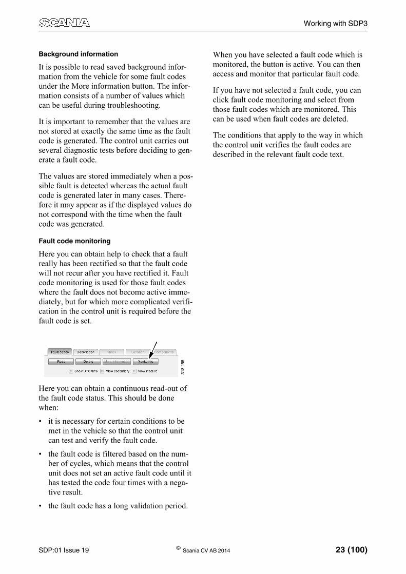
Fault code monitoringHere you can obtain help to check that a fault really has been rectified so that the fault code will not recur after you have rectified it. Fault code monitoring is used for those fault codes where the fault does not become active imme-diately, but for which more complicated verifi-cation in the control unit is required before the fault code is set.
Here you can obtain a continuous read-out of the fault code status. This should be done when:
• it is necessary for certain conditions to be met in the vehicle so that the control unit can test and verify the fault code.
• the fault code is filtered based on the num-ber of cycles, which means that the control unit does not set an active fault code until it has tested the code four times with a nega-tive result.
• the fault code has a long validation period.
When you have selected a fault code which is monitored, the button is active. You can then access and monitor that particular fault code.
If you have not selected a fault code, you can click fault code monitoring and select from those fault codes which are monitored. This can be used when fault codes are deleted.
The conditions that apply to the way in which the control unit verifies the fault codes are described in the relevant fault code text.

24 (100) © Scania CV AB 2014 SDP:01 Issue 19
Working with SDP3
DescriptionA more detailed description is shown here based on where you are in the navigation tree.
There are descriptions for the System, Control unit and Server levels.
Description. The various vehicle electronic control systems with control units and servers are described here.

SDP:01 Issue 19 © Scania CV AB 2014 25 (100)
Working with SDP3
Checking a circuitA circuit diagram for the circuit marked in the navigation tree is shown here. You can read signals from the control unit and activate dif-ferent functions and components in order to check whether the circuit is working as expected. Descriptions can be found in the same window.
If you place the mouse pointer on a cable har-ness in the circuit diagram, the cable marking is displayed.
If you place the mouse pointer on a connection pin, the cable terminal part number, relevant hand crimping tool, dismantling tool and cable marking are displayed.
You can change the size of the circuit diagram with the + and - keys.

26 (100) © Scania CV AB 2014 SDP:01 Issue 19
Working with SDP3
Right-clicking a component in the circuit dia-gram takes you directly to a user function in the user function view.
Navigation from circuit to user function.

SDP:01 Issue 19 © Scania CV AB 2014 27 (100)
Working with SDP3
If you click the symbol to the right of the read value, the value is presented in a diagram.
The diagram is displayed in real time. Example with wheel speed: The curve is recorded as the speed increases/decreases.

28 (100) © Scania CV AB 2014 SDP:01 Issue 19
Working with SDP3
From the server level in the navigation tree, you can carry out a number of checks linked to each server.
Check. A number of checks can also be carried out at the server level. In most cases, the result of the check can be saved and stored in the "Reports" directory created when SDP3 was installed.

SDP:01 Issue 19 © Scania CV AB 2014 29 (100)
Working with SDP3
Activation
When you start up the activation window (1), SDP3 takes control over the inputs and outputs of the control units concerned.
You choose what to activate by entering a value or a status (2). When you click the button (3), the value is sent to the control unit. The current status is displayed to the right of the button.
The activation button works differently depending on what is required for the particular activation being carried out. The following options are available:
• Activation takes place when you click the button and to stop activation you have to click the button again.
• Some activations have a time limit which means that the activation ceases automati-cally after a certain time. Then the button is also reset.
• Spring-loaded button: you have to hold down the button during activation.
When activation ceases, the value is reset to its original level.
It is only when you exit and close the activa-tion window that the control unit regains con-trol over the components concerned.
As a safety feature, activation can always be interrupted by pressing the space bar.

30 (100) © Scania CV AB 2014 SDP:01 Issue 19
Working with SDP3
LocationDiagrams are displayed here, which indicate where on the vehicle a particular electric com-ponent is located. If there are several location diagrams for the components in the circuit, use the arrows below the diagram to move between the diagrams.
If you double-click a diagram, a new window opens to display the diagram. This enables you to have the diagram open while working with other activities in SDP3. The same applies to other diagrams in the program.

SDP:01 Issue 19 © Scania CV AB 2014 31 (100)
Working with SDP3
ComponentsHere you find a more detailed description of the components which are included in a circuit. Select between relevant components in the list above the diagrams.
If there are several component diagrams, use the arrow keys below the diagram to move between the diagrams.

32 (100) © Scania CV AB 2014 SDP:01 Issue 19
Working with SDP3
The connection of controllable components to the control unit is displayed in the navigation tree at system level. Place the mouse pointer on a cable harness to get information about which checks can be carried out on the circuit under the Check tab.
If you press the right mouse button, the text box disappears but the highlighting remains so that you can see the connection.
Place the mouse pointer on a component and press the right mouse button to navigate directly to the particular user function, circuit check or to information about the component. This function works for most components.

SDP:01 Issue 19 © Scania CV AB 2014 33 (100)
Working with SDP3
AdjustingUnder Adjusting, you can view the customer parameters which can be changed and their current values.
The information is retrieved from the control unit and displays the stored value.
During adjustment any applied settings are saved to the SOPS file so that they can be reset when renewing a spare part.
You should have checked the vehicle and recti-fied any fault codes before carrying out an adjustment.
1. To carry out an adjustment, click the Change button.
2. Select a new value.
If a value is changed, a red dot is displayed on the status field for the customer parame-ter. The symbol, a flake, displays the value that was set at the factory.
3. Then click Execute.
When you carry out the adjustment, the changed customer parameters will be marked with a green tick if the adjustment was successful. If the adjustment failed, the red dot will remain for the changed cus-tomer parameters.

34 (100) © Scania CV AB 2014 SDP:01 Issue 19
Working with SDP3

SDP:01 Issue 19 © Scania CV AB 2014 35 (100)
Working with SDP3
CalibrationThere is also an option to calibrate and reset the values in the vehicle control unit.
During calibration it is not possible to save the settings made so that they can be reused when renewing a spare part.
1. Highlight what you wish to calibrate and proceed by clicking the arrows.
2. A wizard will now appear which will help you to carry out the calibration.

36 (100) © Scania CV AB 2014 SDP:01 Issue 19
Working with SDP3
Signal loggingA list of the servers for the vehicle is shown here. The signals are found under the relevant server.
In this view, you can tick the signals you want to take a closer look at. The signals can be recorded and saved in a file, which can then be used for troubleshooting. You can record the signals' values, save them in a file and e.g. send them to Scania for troubleshooting.
1. List of servers.Click a server to see its signals.
2. List of signals.This is where you can select the signals you want to record.
3. List of selected signals.The read value is shown here once logging has started.
4. Buttons for recording.Here, you can start, stop and save the recording. You can also flag particularly interesting parts of the recording by press-ing the Time stamp button. Reading speed is shown in Hz.
5. Buttons to save the signal list and to open previously saved signal lists.

SDP:01 Issue 19 © Scania CV AB 2014 37 (100)
Working with SDP3

38 (100) © Scania CV AB 2014 SDP:01 Issue 19
Working with SDP3
Troubleshoot via user functionHere you can troubleshoot by starting from the vehicle's user functions.
Navigation under User functions is divided up as follows:
1. Vehicle2. Group of user functions:
The user functions are grouped into catego-ries. Gearbox control is one example of a category.
3. User function
One user function in the Gearbox control category is the Opticruise system.
4. Use case
Examples of an Opticruise system use case:
– Activation of automatic gear changing
– Selecting gear manually– Setting the starting gear
Levels when navigating under User functions.

SDP:01 Issue 19 © Scania CV AB 2014 39 (100)
Working with SDP3
The content under the different tabs varies, depending on where you are in the navigation tree.

40 (100) © Scania CV AB 2014 SDP:01 Issue 19
Working with SDP3
The table below gives an indication of what sort of information the tabs contain on the dif-ferent levels.
Fault codes Description Check Function diagram Adjustment
1 Vehicle X
2 Group of user functions
X X
3 User function X X X X
4 Use case X X
5 Scenario (different ways in which the use case can be carried out)
X X

SDP:01 Issue 19 © Scania CV AB 2014 41 (100)
Working with SDP3
Fault codesHere you can see which fault codes are regis-tered for a user function.
Other information relating to fault codes is the same as for fault codes under electrical system.

42 (100) © Scania CV AB 2014 SDP:01 Issue 19
Working with SDP3
DescriptionHere you can obtain a brief description of the vehicle’s user functions.

SDP:01 Issue 19 © Scania CV AB 2014 43 (100)
Working with SDP3
CheckYou can carry out checks on some of the vehi-cle's user functions here. Unlike checks under the Electrical system, these checks may work on several interrelated control units.
1. Highlight the user function you want to check.
2. Press the button on the selected guide to start the guided function.

44 (100) © Scania CV AB 2014 SDP:01 Issue 19
Working with SDP3
Function diagramThe function diagrams which are available for a user function are displayed here. The func-tion diagrams provide a visual representation of the function. They provide an overview of the control units and other components which are involved in a user function in the specific vehicle. They also show the order in which sig-nals travel between the components concerned.
A blue broken arrow (1) shows the influence from the circumstances, e.g. the driver turns the key.
A blue continuous arrow (2) shows conven-tional electrics. There must be circuits in the electrical system view to obtain these arrows, e.g. S4 closes + 24 V to E30.
A black arrow (3) displays CAN messages between different control units.
By right-clicking a component (4), you can go to checking the circuit in the electrical system view.

SDP:01 Issue 19 © Scania CV AB 2014 45 (100)
Working with SDP3
CalibrationHere you can calibrate a user function that extends over several control units.
1. Highlight the user function you want to cal-ibrate.
2. Press the button on the selected guide to start the guided function.

46 (100) © Scania CV AB 2014 SDP:01 Issue 19
Working with SDP3
Troubleshoot using function viewIn the function view you can check, adjust and calibrate at a function level. When a certain level in a main tab is displayed and the view is then changed to another main tab, SDP3 will automatically try to navigate to the correspond-ing level in the new main tab.
The changes take place at function level and are carried out on several control units simulta-neously.

SDP:01 Issue 19 © Scania CV AB 2014 47 (100)
Working with SDP3
CheckHere you can troubleshoot using different guides. The guides are grouped so that all guides needed to troubleshoot a certain func-tion are displayed together, independent of the control units implementing the function.
If any of the control units needed to implement a certain function do not correspond, the func-
tion will be marked with a cross in the naviga-tion tree. The guides for checking the function cannot be started.
1. Select a group in the tree structure.
2. Press the button on the selected guide to start the guided function.
1. Group
2. Guide. Each group may have one or more guides.

48 (100) © Scania CV AB 2014 SDP:01 Issue 19
Working with SDP3
AdjustmentHere you can view the function parameters, i.e. customer parameters grouped per function, which can be changed and their current values. All the parameters affected by a certain func-tion are displayed together. During adjustment the applied settings are saved to the SOPS file so that they can be reset when renewing a con-trol unit.
Check the vehicle and rectify any fault codes before making any adjustments.
In order to carry out an adjustment the control units must be spare parts programmed. If a control unit is not spare parts programmed, the system which the control unit is part of is high-lighted with a yellow dot in the drop-down list (4). Start spare parts programming by pressing the button Spare parts programming. When spare parts programming is completed, the sys-tem is highlighted with a green dot.
If any of the control units needed to implement a certain function do not correspond, the func-tion will be marked with a cross in the naviga-tion tree. Function parameters cannot be adjusted.
On the side of the view there is a link to the user function which is connected to the func-tion parameter. Click a function parameter group and then the link to the user function for more information on how the user function works.

SDP:01 Issue 19 © Scania CV AB 2014 49 (100)
Working with SDP3
Adjust several function parameter groups
1. Select a group in the tree structure.
2. Press Change.
1. Group
2. Change
3. Function parameter groups and function parameters
4. Systems which are included in the function. Yellow highlighting means that the system control unit has not been spare parts pro-grammed. Press the Spare parts program-ming button to carry out spare parts programming of the selected system in the drop-down list.

50 (100) © Scania CV AB 2014 SDP:01 Issue 19
Working with SDP3
1. Select a new value.
If a value is changed, a red dot is displayed on the status field for the function parame-ter. The symbol, a flake, displays the value that was set at the factory.
2. Press Execute.
All control units that are included in the function will be reprogrammed. When you carry out the adjustment, the changed func-tion parameters will be marked with a green tick if the adjustment was successful. If the adjustment failed, the red dot will remain for the changed function parameters.
1. The value of the function parameter
2. Execute

SDP:01 Issue 19 © Scania CV AB 2014 51 (100)
Working with SDP3
Adjust a function parameter group
1. Select the function parameter group to be adjusted.
2. Press Change.
3. Select a new value.
If a value is changed, a red dot is displayed on the status field for the function parame-ter. The symbol, a flake, displays the value that was set at the factory.
4. Press Execute.
All control units that are included in the function will be reprogrammed. When you carry out the adjustment, the changed func-tion parameters will be marked with a green tick if the adjustment was successful. If the adjustment failed, the red dot will remain for the changed function parameters.
1. Function parameter group
2. Function parameter group and function parameter
3. Link to current user function under the Check tab

52 (100) © Scania CV AB 2014 SDP:01 Issue 19
Working with SDP3
CalibrationHere you can carry out calibration using differ-ent guides. The guides are grouped so that all guides needed to calibrate a certain function are displayed together, independent of the con-trol units implementing the function.
If any of the control units needed to implement a certain function do not correspond, the func-
tion will be marked with a cross in the naviga-tion tree. The guides for calibrating the function cannot start.
1. Select a group in the tree structure.
2. Press the button on the selected guide to start the guided function.
1. Group
2. Guide. Each group may have one or more guides.

SDP:01 Issue 19 © Scania CV AB 2014 53 (100)
Working with SDP3
Product informationInformation about how the vehicle is equipped is available here. For example, the user func-tions which are available on the vehicle and electrical information from the chassis specifi-cation are displayed.
Information about the settings of the different control unit parameters is also available here. You can view when and which USB key was connected when the parameters were last changed.
You can also see any local conversions carried out on the vehicle.
Specification information for the vehicle

54 (100) © Scania CV AB 2014 SDP:01 Issue 19
Working with SDP3
ConversionThe Conversion work option is used to carry out "major adjustments" of the vehicle or industrial and marine engine, which are referred to as conversions. The control units affected by a conversion can reset certain con-trol unit settings and calibrations. Make sure that the control units concerned have the cor-rect parameters set and also make sure that after a conversion you calibrate the control units which may have been affected.
Note:Scania cannot accept responsibility for conver-sions carried out on a vehicle or industrial and marine engines which contravene the national regulations in a specific country.
You can also analyse the vehicle's stored oper-ational data either directly in SDP3 or via the menu option View stored operational data. For more information, refer to section Operational data.

SDP:01 Issue 19 © Scania CV AB 2014 55 (100)
Working with SDP3
Local conversionYou can obtain information about any local conversions here. You can carry these out yourself by setting the parameters covered by the conversion. When you choose to carry out the conversion, the affected control units are reprogrammed.
After conversion, you must report the changes to Scania by sending in the changed SOPS file. The report is a prerequisite for being able to show correct vehicle information in Scania Multi.
Procedure1. Start SDP3 and select the Conversion work
option.
2. Read and rectify any fault codes registered in the vehicle.
3. Highlight the vehicle level in the navigation field and select Local conversion (1).
4. Highlight the conversion you wish to carry out and proceed (2).
5. Set the new values for the parameters con-cerned (3).
6. Select OK (4).
7. Save the SOPS file by selecting Save SOPS (5).
8. Calibrate and reset any control units which may have been affected. Adjustment can be carried out from the same view in the pro-gram.
9. Report by sending in the changed SOPS file to Scania.

56 (100) © Scania CV AB 2014 SDP:01 Issue 19
Working with SDP3
Procedure during local conversion. The text on the previous page refers to the numbers in the illus-tration.

SDP:01 Issue 19 © Scania CV AB 2014 57 (100)
Working with SDP3
Factory supported conversionYou need to contact Scania for factory sup-ported conversion.
Regardless of the type of factory supported conversion which is to be carried out, it is always necessary for the SOPS file of the vehi-cle or industrial and marine engine to be sent to Scania.
There are two ways to carry out a factory sup-ported conversion:
• Upload the existing SOPS file onto the SAIL web portal and order an update.
Carry out the conversion that has been ordered using SDP3. If this option is used, there are several possible factory supported conversions. These conversions can consist of an updated SOPS file, software for con-trol units or application data for control units. When selecting a conversion, it is not possible the see which parts the conversion includes.
• Send the existing SOPS file, including a description of the intended conversion to Scania.
Scania will send back an updated file once it has been approved. If this option is used, only the existing SOPS file of the vehicle or industrial and marine engine can be exchanged for an updated file.
Always start by saving the existing SOPS file of the vehicle or industrial and marine engine, basing the update on it. When the file has been saved, no other conversions must be carried out on the vehicle or industrial and marine engine. If a change is made, the contents of the new SOPS file will not correspond to the conditions applicable when the old file was used. It will not then be possible to use the updated SOPS file.

58 (100) © Scania CV AB 2014 SDP:01 Issue 19
Working with SDP3
ProcedureStart the conversion and save the SOPS file.
1. Start SDP3 and select the Conversion work option.
2. Read and rectify any fault codes registered in the vehicle.
3. Highlight the vehicle level in the navigation field and select Adjust (1).
4. Highlight Save existing SOPS file (2) and select Execute (3).
5. Select a suitable location to save the file.
6. Decide whether to use Conversion via the SAIL web portal to update the file or whether to send it to Scania together with an order. The options are described on the following pages.
SDP:01 Issue 19 © Scania CV AB 2014 59 (100)
Working with SDP3
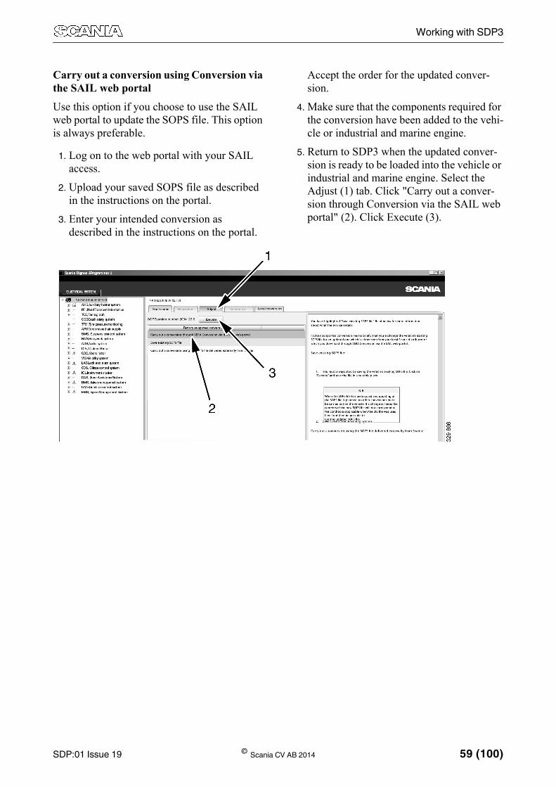
Carry out a conversion using Conversion via the SAIL web portalUse this option if you choose to use the SAIL web portal to update the SOPS file. This option is always preferable.
1. Log on to the web portal with your SAIL access.
2. Upload your saved SOPS file as described in the instructions on the portal.
3. Enter your intended conversion as described in the instructions on the portal.
Accept the order for the updated conver-sion.
4. Make sure that the components required for the conversion have been added to the vehi-cle or industrial and marine engine.
5. Return to SDP3 when the updated conver-sion is ready to be loaded into the vehicle or industrial and marine engine. Select the Adjust (1) tab. Click "Carry out a conver-sion through Conversion via the SAIL web portal" (2). Click Execute (3).

60 (100) © Scania CV AB 2014 SDP:01 Issue 19
Working with SDP3
6. SDP3 will ask you to log on to the SAIL web portal. Enter your user name and pass-word.
7. A work list is downloaded. The procedure for the various steps in the list is shown step by step on the screen. Depending on the contents of the conversion, various proce-dures are displayed. If the contents consist of a SOPS file, the procedure is shown as illustrated. If the update consists of several parts, various procedures will be displayed. Click OK for each procedure when it is fin-ished.
8. When the conversion is complete, a confir-mation is sent to Scania.
9. Operational data is sent to Scania via SDP3.
10. Certain customer settings for customer parameters may have reverted to their default values during loading. Calibrate and reset any control units which may have been affected. Adjustment can be carried out from the same view in the program.
Note:All fault codes are automatically deleted when the work option is finished.
11. If software in one of the control units of the vehicle or industrial and marine engine has been updated, the work steps under Finish-ing work in the ECU update work option must be carried out.
A conversion procedure is displayed step by step on the screen. This is the procedure for an updated SOPS file.
A separate procedure is displayed when the SOPS file is loaded. Information is also pro-vided about the results of each stage of the pro-cedure.

SDP:01 Issue 19 © Scania CV AB 2014 61 (100)
Working with SDP3
Carry out a conversion using SOPS file delivered externally from Scania
This option applies if you choose to send the SOPS file to Scania and let Scania send back an update.
1. Describe your intended conversion in detail and enclose the description with the SOPS file when you send it to your distributor.
2. Make sure that the components required for the conversion have been added to the vehi-cle or industrial and marine engine.
3. Use SDP3 when you have received the updated file. Select the Adjust (1) tab. Click "Carry out a conversion using the SOPS file delivered externally from Scania" (2). Click Execute (3).

62 (100) © Scania CV AB 2014 SDP:01 Issue 19
Working with SDP3
4. Open the SOPS file. The file will then start loading.
Note:Note: The SOPS file to be loaded may be called either chassinummer.version.imp.sops or chassinummer.version.maps.sops
5. A dialogue box displays information about the new SOPS file and the current SOPS file of the vehicle or industrial and marine engine. Start the conversion by clicking OK.
6. The procedure is shown step by step on the screen. The SOPS file is verified and the control units concerned are updated. Follow the procedure on the screen.
7. Notify Scania when the conversion is com-plete and the SOPS file is loaded.
8. Certain customer settings for customer parameters may have reverted to their default values during loading. Calibrate and reset any control units which may have been affected. Adjustment can be carried out from the same view in the program.
Note:All fault codes are automatically deleted when the work option is finished.
When loading the SOPS file the procedure is shown step by step on the screen. Information is provided about the results of each step of the procedure.

SDP:01 Issue 19 © Scania CV AB 2014 63 (100)
Working with SDP3
InspectionIn the Inspection work option you can access limited parts of the program which are required during an inspection.
The parts which are currently accessible are connecting, checking the control unit parame-ters and support for reading fault codes.
You can analyse the vehicle's stored opera-tional data either directly in SDP3 or via the menu option View stored operational data. For more information, refer to section Operational data.

64 (100) © Scania CV AB 2014 SDP:01 Issue 19
Working with SDP3
ECU updateSupport is provided here to update the software of control units using SDP3. In the ECU update work option you can find out about the ECU updates available for the specific vehicle or industrial and marine engine.
After the SOPS file is sent to Scania, the ECU updates that are available are checked and dis-played. You can select which updates to carry out.
In order to carry out an ECU update, the com-puter must have a network connection to Sca-nia and you must have SAIL access. You also need to belong to the group VERA_users. More information about how it works can be found on the Service Development website under Workshop Tools & Equipment. You can access the website via SAIL.
When you enter the work option ECU update, you can access the electrical system view where you can check and clear fault codes before starting the software update.
When you start the ECU update, instructions are given in the program.
You can also analyse the vehicle's stored oper-ational data either directly in SDP3 or via the menu option View stored operational data. For more information, refer to section Operational data.
ScopeThe work comprises:
• preparations
• connecting to Scania and downloading new software which is stored temporarily on your local computer
• updating the control unit
• finishing work for checking any fault codes in SDP3.

SDP:01 Issue 19 © Scania CV AB 2014 65 (100)
Working with SDP3
PreparationsNote:The vehicle must be stationary and the engine must be switched off with the 15 voltage acti-vated.
1. Check that the vehicle or industrial and marine engine is fully functioning without fault codes and with control units that have undergone spare parts programming.
2. Check that the batteries of the vehicle or industrial and marine engine are charged or that there is a power supply.
3. Check that the computer is connected to the vehicle or industrial and marine engine and is connected to the internet.
The following conditions must be met in order to carry out an ECU update using SDP3.
1. You must have a valid SAIL account.
2. Your access must include the VERA_users group.

Working with SDP3
66 (100) © Scania CV AB 2014 SDP:01 Issue 19
3. Check that the computer is not set to shut down or to enter power save mode. Change the setting via Start>Settings>Control panel, see Figures 1 and 2.
4. Check that the VCI is connected correctly to the vehicle or industrial and marine engine.
Note:Disconnect large current consumers such as trailers, auxiliary lamps or similar in order to prevent the batteries from being discharged.
Figure 1
Figure 2

SDP:01 Issue 19 © Scania CV AB 2014 67 (100)
Working with SDP3
Work descriptionConnection to vehicle
1. Connect the computer to the vehicle or industrial and marine engine via the VCI connection.
2. Start SDP3.
Downloading new software
1. Click the ECU update button, see figure 3.
2. A new window opens. Click the Start but-ton.
Figure 3

Working with SDP3
68 (100) © Scania CV AB 2014 SDP:01 Issue 19
A new window opens which indicates that SDP3 is connected to Scania, see Figure 4. A new window also opens for logging on to Scania.
3. Enter your user name and password for SAIL.
Note:If the user name or the password is entered incorrectly 3 times the user is blocked from SAIL. The user is blocked without any prior warning.
Figure 4

SDP:01 Issue 19 © Scania CV AB 2014 69 (100)
Working with SDP3
4. When you have logged on successfully, the SOPS file is sent to Scania, see Figure 5.
5. The SOPS file is checked to find out if there are any ECU updates available for the specific vehicle or industrial and marine engine, see Figure 6.
6. A list of available ECU updates is pre-sented, see Figure 7.
The list contains two possible types of ECU updates: Optional and Campaign.
An optional ECU update is enhanced soft-ware recommended by Scania.
A campaign ECU update is a compulsory Scania software update.
Figure 5
Figure 6
Figure 7

70 (100) © Scania CV AB 2014 SDP:01 Issue 19
Working with SDP3
Description of ECU update list
1. The numeral on the right of the list shows how many control units are affected by an ECU update. If several control units (2 or more) are affected, all control units con-nected to the ECU update will be updated.
2. The titles of the ECU updates are presented in the list first. Click the arrow beside each title to view the contents.
3. A list is displayed under each ECU update with the titles of the ECU updates that are included. Click the arrow to see a description of the ECU update.
4. A description of the ECU update can be found here. If several control units are affected, a description is provided under each title.
5. There is an installation button for each ECU update. Click the button to start installing the ECU update. If several control units are affected by the ECU update, all updates will be installed at the same time.

SDP:01 Issue 19 © Scania CV AB 2014 71 (100)
Working with SDP3
Updating software in the control unit
1. A check is carried out to ensure that the SOPS file and the affected control unit cor-respond, see Figure 8.
2. SDP3 retrieves information about the selected ECU update.
3. A new window opens in SDP3. A new check is carried out to ensure that the new software corresponds to the control unit in the vehicle or industrial and marine engine. The software is then downloaded to SDP3.
A new dialogue box is displayed. Read through the text and follow the instructions, see Figure 9. Click OK to start the update of the control unit.
4. The control unit is updated, see Figure 10. The update takes a few minutes. Click OK when the update is complete.
Figure 8
Figure 9
Figure 10

72 (100) © Scania CV AB 2014 SDP:01 Issue 19
Working with SDP3
IMPORTANT!
If the update of the control unit is cancelled:
• Save a screenshot from the time the error occurred.
• Save the log files. Normally, these can be found in the folder Logfiles (SDP3) on the desktop.
Examples of log files are:
– ApplicationLog.txt
– DataLinkLog.txt– SDP3Tool.log– TransportLog.txt– SpinLog.txt
It is important to save the log files at the exact time the fault occurred.
• Exit SDP3 and disconnect the 15 voltage of the vehicle or industrial and marine engine. Activate the 15 voltage again and start SDP3. Click the ECU update button and make a new attempt to update the control unit software.
If the second attempt also fails, save a new screenshot. Create a fault report and attach all log files and screenshots together with operational data.
The file containing operational data has the chassis serial number as part of its file name. See the example below.
YS2P4X20092047668 2009-08-18 kl 1754.txt

SDP:01 Issue 19 © Scania CV AB 2014 73 (100)
Working with SDP3
5. Spare parts programming of the control unit takes place and the SOPS file is updated, see Figure 11.
6. Operational data is sent to Scania via SDP3, see Figure 12.
7. When spare parts programming is complete a new window opens, see Figure 13. The instructions in the window correspond to the instructions under the heading Finishing work. Close the window by clicking OK.
Note:All fault codes are automatically deleted when the work option is finished.
Figure 11
Figure 12
Figure 13

Working with SDP3
74 (100) © Scania CV AB 2014 SDP:01 Issue 19
Finishing work1. Cut the power to the vehicle or industrial
and marine engine by switching off the starter key or a corresponding switch.
2. Wait for 30 seconds.
3. Activate 15 voltage.
4. Check whether there are any remaining fault codes in the control unit. If there are any fault codes they must be rectified before test driving the vehicle or industrial and marine engine.
5. Test drive the vehicle or industrial and marine engine.
6. Check whether any new fault codes have been generated and rectify these if this is the case. After this the software update is complete.

SDP:01 Issue 19 © Scania CV AB 2014 75 (100)
Working with SDP3
BodyworkThe Bodywork work option provides access to the restricted parts of the program required to fit the bodywork to the vehicle.
The checking function is fully accessible, while the adjustment function is limited according to the needs of the bodybuilder.
You can also analyse the vehicle's stored oper-ational data either directly in SDP3 or via the menu option View stored operational data. For more information, refer to section Operational data.

76 (100) © Scania CV AB 2014 SDP:01 Issue 19
Working with SDP3
ConnectingGeneralNote:In order for SDP3 to be able to communicate with certain control units, the systems must be activated. This applies to the auxiliary heater and radio, which must be turned on when con-necting.
The response time of individual control units varies after the starter key has been set to drive position. If SDP3 starts control unit identifica-tion too soon after the starter key has been set to drive position, some control units may not respond. In that case, re-establish the connec-tion.
SPD3 carries out a number of checks when connecting to the vehicle or industrial and marine engine. During the connection phase you will be given information about the activi-ties being carried out by SDP3. If a fault occurs during the connection, you will be informed about this and guided through with the help of the program.
SDP3 reads and compares, for example, the information in the SOPS file with the informa-tion available in the control units. If there are discrepancies you will be informed about this, and if spare parts programming needs to be car-ried out on one or more control units, SDP3 will provide this option.

SDP:01 Issue 19 © Scania CV AB 2014 77 (100)
Working with SDP3
Procedure when connectingThe basic procedure when connecting to a vehicle is displayed here. With some types of work the procedure only includes parts of the steps below.
• SDP3 connects to the vehicle.
• SDP3 retrieves vehicle information from the vehicle.
• SDP3 identifies the vehicle's control units.
If any control unit fails to respond, this will be indicated at the bottom of the connection window.
• SDP3 reads the SOPS file from the coordi-nator and instrument cluster which are the control units containing a SOPS file.
• SDP3 verifies the SOPS file. This means that the program checks both SOPS strings and checks that they are the same.
• SDP3 retrieves system information about the control units from its database.
• SDP3 checks identified control units against the SOPS file.
If one of the control units does not corre-spond to the SOPS file, you will be informed about this and about how to pro-ceed.
• SDP3 retrieves information about the prod-uct type from the SOPS file. This means that SDP3 checks whether it is connected to a truck, bus or industrial and marine engine.
• SDP3 checks the identity of the control units.
• SDP3 updates the SOPS file with the iden-tity of the control units.
• SDP3 retrieves information about the updates.
• SDP3 retrieves the vehicle settings from the SOPS file.
SDP3 compares the control unit configura-tion with the contents of the SOPS file.
If the configuration differs, you will have the opportunity to carry out spare parts pro-gramming of the control units which are not configured correctly.
• SDP3 reads fault codes from the control units.
• SDP3 retrieves other information from its database.
• SDP3 checks the conditions to remain con-nected.
• SDP3 finishes retrieving vehicle informa-tion and the OK button becomes available.

78 (100) © Scania CV AB 2014 SDP:01 Issue 19
Working with SDP3
Spare parts programmingIf the control unit configuration does not corre-spond to the contents of the SOPS file (which can be due to one of the control units having been renewed), SDP3 will propose spare parts programming.
During spare parts programming the parame-ters in the control unit are changed to corre-spond to the contents in the SOPS file.
SDP3 guides you through spare parts program-ming.
After renewing one or more control units, SDP3 should always be connected in order to carry out spare parts programming before the work is finished.

SDP:01 Issue 19 © Scania CV AB 2014 79 (100)
Working with SDP3
CommunicationInformation is constantly being exchanged between SDP3 and the control units in the vehicle/engine SDP3 is connected to. Signals and messages are sent in both directions. Unex-pected interference in communication can occur which affects the ability to, for example, read and display information from the control units.
When interference in communication occurs, you will be informed of this, either in the form of a fault message or via a symbol.
It may be worth knowing that disruptions to communication which occur after you have connected the program and started work are usually temporary. If the fault message indi-cates a cause, check what is indicated and try again. If no cause is given, try again several times to see whether the communication prob-lems disappear. If the fault does not seem to affect the work you are doing, you can ignore the fault message and continue.
Fault handling in the program is being continu-ously improved.
The document entitled Communication prob-lems, which can be accessed from the Help menu, provides more detailed information about disruptions to communication.

80 (100) © Scania CV AB 2014 SDP:01 Issue 19
Working with SDP3
Graphic symbols in the programExplanations of the graphic symbols used in the program are provided below.
Some symbols may be combined to display more than one state.
The control unit does not respond.
The control unit responds but the information does not exist in the SOPS file. Control units may have been fitted and not programmed correctly.
The configuration in the control unit differs from the configuration in the SOPS file.
The VIN or engine serial number in the control unit differs from the VIN or engine serial number in the SOPS file.
The control unit responds but there is no support for it in SDP3. There is either no support at all for the assembly part number or there is no support for the assembly part number combined with the vehicle or I/M engine configuration.
The control unit responds, but has incomplete software.
There are fault codes associated with the system or user function.
The program did not find a SOPS file.
The control unit has been manipulated.
One of the control units included in the group of functions does not respond.
One of the control units included in the function does not respond.
One of the control units included in the group of functions has a VIN or engine serial number which differs from the VIN or engine serial number in the SOPS file.
One of the control units included in the function has a VIN or engine serial number which differs from the VIN or engine serial number in the SOPS file.
There are new product updates available for the vehicle

SDP:01 Issue 19 © Scania CV AB 2014 81 (100)
Working with SDP3
Status field
A valid USB key is connected.
No valid USB key is connected.
No contact between VCI and vehicle or I/M engine.
No contact between computer and VCI.
Communication between computer and vehicle or I/M engine is working.
SDP3 is in contact with a local network.
SDP3 is not in contact with any local network.
Air pressure for brake circuit 1.
Air pressure for brake circuit 2.
Normal battery voltage, more than 24.5 V.
Low battery voltage, between 22.0 - 24.5 V. The system is working but the battery charger should be connected.
Incorrect battery voltage, less than 22 V. The system is not working and the battery charger must be connected.
The vehicle odometer reading. For I/M engines the operating time is shown.

Working with SDP3
82 (100) © Scania CV AB 2014 SDP:01 Issue 19
Certificate for services in SDP3 is installed.
Certificate for services in SDP3 has expired.
2 months remain of Certificate for services in SDP3.
Certificate for services in SDP3 is missing.

SDP:01 Issue 19 © Scania CV AB 2014 83 (100)
Working with SDP3
Fault codes
Fault code.
Primary or secondary fault code.
The fault code was registered as active when fault codes were last read.
Number of times a fault code has been registered as active.
Vehicle system time at which the fault code was last registered as active.

Working with SDP3
84 (100) © Scania CV AB 2014 SDP:01 Issue 19
Read/activate
The control unit recognises an activity (input signal, output signal or communication).
The control unit detects that a received value (of a signal or a message) is outside the expected range.
Used in the Operational data view. The value for this variable cannot be shown for a time interval. The value shown is always the value for the To date.
Communication works well but the control unit does not recognise the value received. The symbol is also displayed for components which are not valid for the vehicle or if no calibration has been carried out.
Interference in communication between the control unit and SDP3.
The control unit recognises an activity (input signal, output signal or communication) for a given function.
The circuit to the control unit input is open (not closed to ground).
The circuit to the control unit input is closed (to +24 V).
The circuit to the control unit input is open (not closed to ground or to +24 V).
The circuit to the control unit is closed (to ground).

SDP:01 Issue 19 © Scania CV AB 2014 85 (100)
Working with SDP3
Demo modeThe USB key must be connected in order to run the program in demo mode. VCI does not need to be connected.
Starting and exiting demo modeDemo mode can be found under File in the menu. When you start demo mode, you have the option of selecting from a number of demo vehicles which have been included.
If you have saved information from your own vehicles, navigate to the folder where the files are saved and select the file you wish to use from there.
Demo mode is started and stopped from File.

86 (100) © Scania CV AB 2014 SDP:01 Issue 19
Working with SDP3
This is how demo mode worksThe information displayed in demo mode has been provided by real vehicles and has been recorded and saved in the program.
The program works in the same way as it would if it was connected to a vehicle. The pro-gram "does not know" that it is running in demo mode. The saved information represents the program's communication with the vehicle control units.
If you choose to do something which means that the program is expecting more information than is available in the saved vehicle informa-tion, the program will interpret this as an inter-ruption of communication with a control unit.
An example of this is when the program sends a new value to a control unit and expects to receive a modified value back.
SDP3 will then think that contact has been lost with the control unit and will work as it would during normal fault handling.

SDP:01 Issue 19 © Scania CV AB 2014 87 (100)
Working with SDP3
Saving and printing vehicle informationYou can save selected information from the connected vehicle and store it in any folder on the computer. Access the File menu and select from:
1. Save vehicle informationWhen you select this option a large amount of data from the vehicle is automatically saved in a text file. This can only be carried out outside work in progress, i.e. before you have chosen a job type. You can then use the saved file to view the vehicle in demo mode.
2. Save SOPS fileThe vehicle's current SOPS file can be read and saved here.
3. SaveIf you place yourself at circuit level in the navigation tree and select Save, the selected information is saved in a PDF file. A win-dow opens in which you can tick those parts of the work in progress you wish to save. Both illustrations and text are saved in the PDF file.
You can save and print vehicle information via the File menu.
Working with SDP3
88 (100) © Scania CV AB 2014 SDP:01 Issue 19
4. Open the saved file
Open the saved files stored in any folder here.
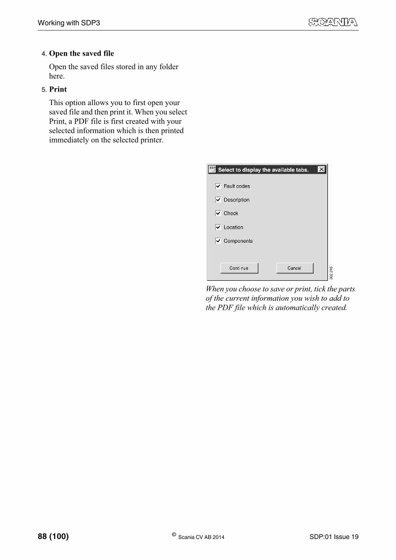
5. Print
This option allows you to first open your saved file and then print it. When you select Print, a PDF file is first created with your selected information which is then printed immediately on the selected printer.
When you choose to save or print, tick the parts of the current information you wish to add to the PDF file which is automatically created.

SDP:01 Issue 19 © Scania CV AB 2014 89 (100)
Working with SDP3
Remote DiagnosticsFunction to carry out diagnostics on a vehicle remotely. For more information about the web application Remote Diagnostics, see Remote Diagnostics on TIL.
Certificate for services in SDP3To carry out Remote Diagnostics, the Certifi-cate for services in SDP3 must be installed on the computer. If the certificate is installed, an icon will be visible in the status field. For more information about the icons, refer to section Graphic symbols in the program.
To install a Certificate for services in SDP3, contact your SAIL administrator.
For more information about the certificate and the required roles, see document Certificate for services in SDP3 under Scania Diagnos & Pro-grammer 3, Other information on TIL.
Working with Remote DiagnosticsIn order to carry out diagnostics remotely the following is needed:
• Certificate for services in SDP3, for more information about the certificate and roles, see Certificate for services in SDP3 on TIL.
• Vehicle VIN code
• Request ID
• Readout ID

Working with SDP3
90 (100) © Scania CV AB 2014 SDP:01 Issue 19
1. Start Remote diagnostics via menu options under the File menu.
2. Fill in the vehicle VIN code, request ID and readout ID in the relevant field.
3. Click on the Check and Adjust button.
4. SDP3 checks if the current remote reading of diagnostic data has been retrieved already. If not, a remote reading of diagnos-tic data is retrieved and saved locally on the computer. This requires an internet connec-tion.
If a remote reading of diagnostic data has been retrieved already, a check is carried out to ensure that the readout is compatible with the current version of SDP3.
5. The remote reading of diagnostic data is opened in SDP3.
Observe that it is only possible to read the information in the remote reading of diag-nostic data. If there is a need to program, calibrate, adjust or carry out any other changes, SDP3 must be connected to the vehicle in question.
342
927
342
926

SDP:01 Issue 19 © Scania CV AB 2014 91 (100)
Working with SDP3
Operational dataThere are several options for working with operational data via SDP3: view operational data in SDP3, upload operational data to the SVAP portal, and view operational data in the SVAP portal.
If a vehicle has a recurring issue and is brought into the workshop several times, the mechanic can compare operational data from the differ-ent times. The operational data can also be read using a complete reading via Remote Diagnos-tics. This is useful when troubleshooting.
View operational data in SDP3In the Operational data view the mechanic can see the vehicle's operational data directly in SDP3.
Certificate for services in SDP3To see centrally stored operational data in SDP3, a Certificate for services in SDP3 must be installed on the computer. If the certificate is installed, an icon will be visible in the status field. For more information about the icons, refer to section Graphic symbols in the pro-gram.
To install a Certificate for services in SDP3, contact your SAIL administrator.
For more information about the certificate and the required roles, see document Certificate for services in SDP3 under Scania Diagnos & Pro-grammer 3, Other information on TIL.
Working with operational data in SDP3The mechanic can choose between viewing the total operational data of the vehicle or to com-pare operational data which has been read at different times. Operational data is automati-cally read when the mechanic connects the vehicle to SDP3 and it is then saved locally on the computer. If there is an internet connection, operational data is also uploaded to the central database automatically.
The mechanic can choose between viewing operational data stored locally (no certificate
required), if available on the computer, or oper-ational data stored in the central database (cer-tificate required). An internet connection is required in order to obtain access to the central database. It is recommended to first choose the central database as the source as this contains all operational data irrespective of workshop. In addition, operational data in the central data-base is checked thoroughly. If the internet con-nection is interrupted, SDP3 automatically displays operational data stored locally.

92 (100) © Scania CV AB 2014 SDP:01 Issue 19
Working with SDP3
Proceed as follows:
1. Select the server for the current system.
2. Select the source from the drop-down list. The available sources are operational data stored locally and operational data stored in a central database.
3. Select the start date and the end date in the drop-down lists. Select dates for the read-ings you are interested in for troubleshoot-ing.
1. Source. Select to retrieve data stored locally or from the central database.
2. From date. Select a date from the drop-down list.
3. Until date. Select a date in the drop-down list.
4. Operational data for selected system is pre-sented in graphs, tables and individual val-ues.

SDP:01 Issue 19 © Scania CV AB 2014 93 (100)
Working with SDP3
View operational data in the SVAP portalVia the menu selection View stored operational data, the mechanic can look at stored opera-tional data in the SVAP portal. A SAIL account is required to gain access to opera-tional data in the SVAP portal.
There is also an option here to save the file with vehicle data. The file that is saved con-tains the same information as that saved from the Save vehicle information menu option. The file can be used to view the operational data later via the SVAP website or to view the vehi-cle in demo mode. For more information on how to upload files to SVAP, see VERA:02 VERA Operational Analysis User Instruc-tions, which are available on TIL.
When you access and view stored operational data the file will be sent to Scania.
Stored operational data can be found under View.

Working with SDP3
94 (100) © Scania CV AB 2014 SDP:01 Issue 19
To view stored operational data, use SDP3 to access the SVAP website. It is therefore neces-sary for the computer to have a network con-nection to Scania.
You must belong to the group VERA_users to gain access to stored operational data via the SVAP portal. More information about the group VERA_users can be found on the Ser-vice Development website under Workshop Tools & Equipment. You can access the web-site via SAIL.
Proceed as follows to analyse and send stored operational data:
1. Select Stored operational data under View in the menu.
2. Log in using your SAIL identity in the login dialogue which is displayed.
3. Then follow the instructions given in the program.

SDP:01 Issue 19 © Scania CV AB 2014 95 (100)
Working with SDP3
FindSelect Find under View in the menu to access the SDP3 search function.
Select the category and search conditions by clicking the arrow on the right of the relevant box in the search window. Then click the Search button. The categories that you can search on are:
• Fault code: Optional search conditions are system family and fault code designation. The full description of the fault code is dis-played first, followed by clickable links to the circuits and user functions affected by the fault code. All fault codes can be searched, regardless of whether they are active or not.
• Component: Optional search conditions are component family and component code. The search has given hits on the circuits and user functions where a selected component is present. The hits are displayed as clicka-ble links.
• Cable marking: Optional search conditions are system family and serial number in cable marking. The search has given hits on the circuits and user functions where a selected cable is fitted. The hits are dis-played as clickable links.
The search function can be found under View in the menu.

Working with SDP3
96 (100) © Scania CV AB 2014 SDP:01 Issue 19
Viewing all fault codesSDP3 can also display fault codes that have not been generated. Go to the View menu:
• Select All fault codes if you want to see all the fault codes that can be generated, what-ever the vehicle. SDP3 does not need to be connected to the vehicle or VCI.
• If SDP3 is connected, you can select the option Fault codes in vehicle. This displays all the fault codes that can be generated in the vehicle concerned.

SDP:01 Issue 19 © Scania CV AB 2014 97 (100)
Working with SDP3
You can search for fault codes by system and by control unit assembly part number. You can also search for individual fault codes via the fault code number. A separate window opens which remains available while you work on other activities in SDP3.

Working with SDP3
98 (100) © Scania CV AB 2014 SDP:01 Issue 19
Product updateSDP3 has the option of displaying the product updates available for the vehicle. The product updates can be shown from all work options, and they are carried out from the work options Conversion or ECU update.
When product updates are available for a sys-tem, a symbol will be visible in the tree struc-ture. To view available updates, right-click on the tree structure and select Show updates, or use the menu selection Updates in the menu View.
View product updates by right-clicking.The symbol for available product updates is visible next to the system name.
View product updates using menu option.The symbol for available product updates is visible next to the system name.

SDP:01 Issue 19 © Scania CV AB 2014 99 (100)
Working with SDP3
HelpYou can obtain information on SDP3 by look-ing at a number of help documents. The help documents are found under the Help menu.
The following help documents are available:
1. User instructions: description of how to use SDP3.
2. Release notes: descriptions of what is new in the latest version of SDP3.
3. Display supported assembly part numbers: a list of which control units SDP3 supports.
4. Communication problems: describes how to troubleshoot a communication problem between SDP3 and the control units.
5. Fault reporting: a description of how to report faults in SDP3.
6. Create data file for fault report: This zip file contains the SDP3 log files and a snapshot when the fault occurred it is generated auto-matically and saved in the same directory as the log files.
7. About SDP3: general version information about SDP3.

100 (100) © Scania CV AB 2014 SDP:01 Issue 19
Fault handling
Fault handlingElectromagnetic fieldsScania VCI and most of the computers on the market are protected against the electromag-netic fields which are generated by all electri-cal equipment.
However, this protection is limited and is not always sufficient to allow uninterrupted com-munication. Take care when using the pro-grams close to the following equipment:
• Mobile phones and transmitters
• Electric welders
• Power supply installations, e.g. thyristor units
SDP3 crashes under work in progressIf SDP3 crashes under work in progress a crash file will be created when restarting. The file is called craschfile.zip and is saved automatically in the directory where the log files are stored. The file contains information on what was done before the crash.
Rebooting a wizard that is stuckIf a wizard has got stuck in a loop, proceed as follows to reboot the wizard:
Hold the space bar depressed while at the same time clicking the left-hand mouse button. The wizard will then reboot.