SDM630MCT-MBUS V2
36
EASTRON SDM630M CT User Manual SDM630MCT-MBUS V2 DIN Rail Energy Meter for Single and Three Phase Electrical Systems Measures kWh Kvarh, KW, Kvar, KVA, P, F, PF, Hz, dmd, V, A, THD,etc. Bi-directional measurement IMP & EXP Two pulse outputs MBUS Din rail mounting 35mm 1/5A CT connection Better than Class 1 / B accuracy USER MANUAL 2016 V1.4 EASTRON Germany (B+G e-tech GmbH) Franz-Mehring Str. 36 • DE 01979 Lauchhammer • Germany ww.eastron-germany.de
Transcript of SDM630MCT-MBUS V2
EASTRON SDM630M CT User Manual
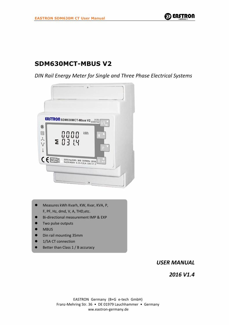
SDM630MCT-MBUS V2
DIN Rail Energy Meter for Single and Three Phase Electrical Systems
Measures kWh Kvarh, KW, Kvar, KVA, P,
F, PF, Hz, dmd, V, A, THD,etc.
Bi-directional measurement IMP & EXP
Two pulse outputs
MBUS
Din rail mounting 35mm
1/5A CT connection
Better than Class 1 / B accuracy
USER MANUAL
2016 V1.4
EASTRON Germany (B+G e-tech GmbH)Franz-Mehring Str. 36 • DE 01979 Lauchhammer • Germany
ww.eastron-germany.de

EASTRON SDM630M CT User Manual
- 1 -
Introduction
This document provides operating, maintenance and installation instructions. The unit measures
and displays the characteristics of single phase two wires (1p2w), three phase three wires(3p3w,)
and three phase four wires(3p4w) supplies, including voltage, frequency, current, power ,active
and reactive energy, imported or exported. Energy is measured in terms of kWh, kVArh.
Maximum demand current can be measured over preset periods of up to 60minutes. In order to
measure energy, the unit requires voltage and current inputs in addition to the supply required to
power the product. The requisite current input(s) are obtained via current transformers(CT).
This meter can be configured to work with a wide range of CTs, giving the unit a wide range of
operation. Built-in interfaces provides pulse and mbus outputs. Configuration is password
protected.
This unit can be powered from a separate auxiliary (AC or DC) supply. Alternatively it can be
powered from the monitored supply, where appropriate.
Unit Characteristics
The Unit can measure and display:
Line voltage and THD% (total harmonic distortion) of all phases
Line Frequency
Currents, Current demands and current THD% of all phases
Power, maximum power demand and power factor
Active energy imported and exported
Reactive energy imported and exported
The unit has password-protected set-up screens for:
Changing password
Supply system selection 1p2w, 3p3w,3p4w
Demand Interval time
Reset for demand measurements
Pulse output duration
Two pulse output indicates real-time energy measurement. An mbus output allows remote
monitoring from another display or a computer.
Current Transformer Primary Current
The unit can be configured to operate with CT ratio between primary current and secondary
current. The secondary CT has two options: 1A/5A
Mbus
This uses an MBus port with EN13753-3 protocol to provide a means of remotely monitoring and
controlling the Unit.
Set-up screens are provided for setting up the MBus port.
EASTRON SDM630M CT User Manual
- 2 -
Pulse output
This provides two pulse outputs that clock up measured active and reactive energy. The constant
for active energy is 3200imp/kWh(Terminals 10&11). The pulse width for pulse 1(Terminals 9&10)
can be set from the set-up menu.
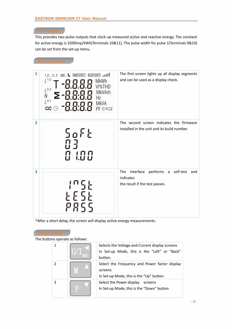
Start Up Screens
1 The first screen lights up all display segments
and can be used as a display check.
2 The second screen indicates the firmware
installed in the unit and its build number.
3 The interface performs a self-test and
indicates
the result if the test passes.
*After a short delay, the screen will display active energy measurements.
Measurements
The buttons operate as follows:
1 Selects the Voltage and Current display screens
In Set-up Mode, this is the “Left” or “Back”
button.
2 Select the Frequency and Power factor display
screens
In Set-up Mode, this is the “Up” button
3 Select the Power display screens
In Set-up Mode, this is the “Down” button

EASTRON SDM630M CT User Manual
- 3 -
4 Select the Energy display screens
In Set-up mode, this is the “Enter” or “Right”
button
Voltage and Current
Each successive pressing of the button selects a new range:
1-1 Phase to neutral voltages(3p4w)
1-2 Phase to neutral voltages(3p3w)
2 Current on each phase
3-1 Phase to neutral voltage THD%(3p4w)
3-2 Phase to neutral voltage THD%(3p3w)

EASTRON SDM630M CT User Manual
- 4 -
4 Current THD% for each phase
Frequency and Power factor and Demand
Each successive pressing of the button selects a new range:
1 Frequency and Power Factor (total)
2 Power Factor of each phase
3 Maximum Current Demand
4 Maximum Power Demand
EASTRON SDM630M CT User Manual
- 5 -
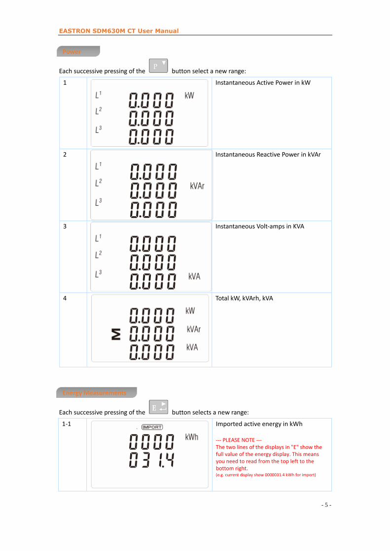
Power
Each successive pressing of the button select a new range:
1 Instantaneous Active Power in kW
2 Instantaneous Reactive Power in kVAr
3 Instantaneous Volt-amps in KVA
4 Total kW, kVArh, kVA
Energy Measurements
Each successive pressing of the button selects a new range:
1-1 Imported active energy in kWh
--- PLEASE NOTE ---The two lines of the displays in "E" show the full value of the energy display. This means you need to read from the top left to the bottom right.(e.g. current display show 0000031.4 kWh for import)
EASTRON SDM630M CT User Manual
- 6 -
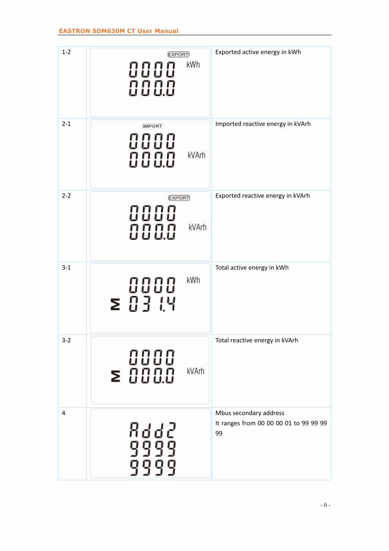
1-2 Exported active energy in kWh
2-1 Imported reactive energy in kVArh
2-2 Exported reactive energy in kVArh
3-1 Total active energy in kWh
3-2 Total reactive energy in kVArh
4 Mbus secondary address
It ranges from 00 00 00 01 to 99 99 99
99
EASTRON SDM630M CT User Manual
- 7 -
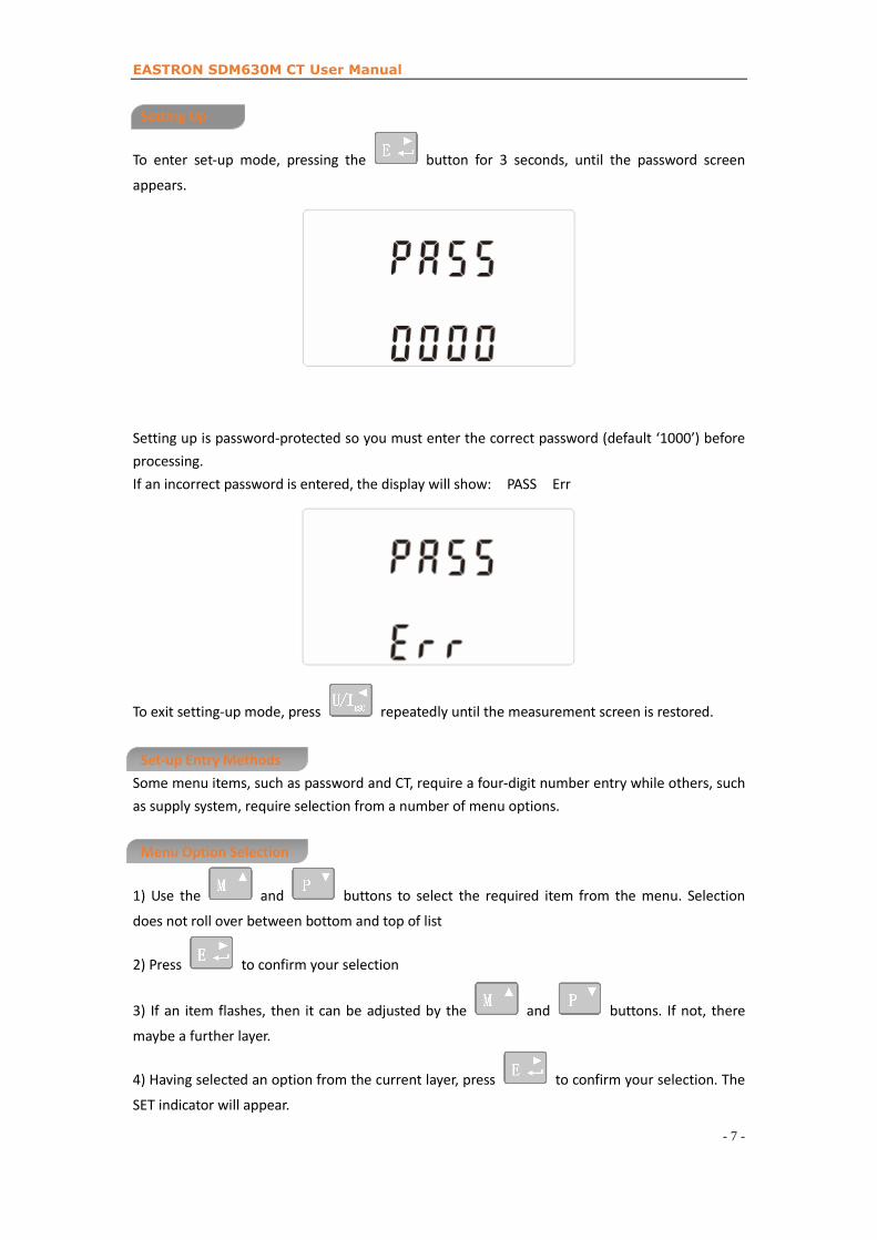
Setting Up
To enter set-up mode, pressing the button for 3 seconds, until the password screen
appears.
Setting up is password-protected so you must enter the correct password (default ‘1000’) before
processing.
If an incorrect password is entered, the display will show: PASS Err
To exit setting-up mode, press repeatedly until the measurement screen is restored.
Set-up Entry Methods
Some menu items, such as password and CT, require a four-digit number entry while others, such
as supply system, require selection from a number of menu options.
Menu Option Selection
1) Use the and buttons to select the required item from the menu. Selection
does not roll over between bottom and top of list
2) Press to confirm your selection
3) If an item flashes, then it can be adjusted by the and buttons. If not, there
maybe a further layer.
4) Having selected an option from the current layer, press to confirm your selection. The
SET indicator will appear.

EASTRON SDM630M CT User Manual
- 8 -
5) Having completed a parameter setting, press to return to a higher menu level. The
SET indicator will be removed and you will be able to use the and buttons for
further menu selection.
6) On completion of all setting-up, press repeatedly until the measurement screen is
restored.
Number Entry Procedure
When setting up the unit, some screens require the entering of a number. In particular, on entry
to the setting up section, a password must be entered. Digits are set individually, from left to
right. The procedure is as follows:
1) The current digit to be set flashes and is set using the and buttons
2) Press to confirm each digit setting. The SET indicator appears after the last digit has
been set.
3) After setting the last digit, press to exit the number setting routine. The SET indicator
will be removed.
Change password
1
Use the and to choose
the change password option
2-1
Press the to enter the change
password routine. The new password
screen will appear with the first digit
flashing
EASTRON SDM630M CT User Manual
- 9 -
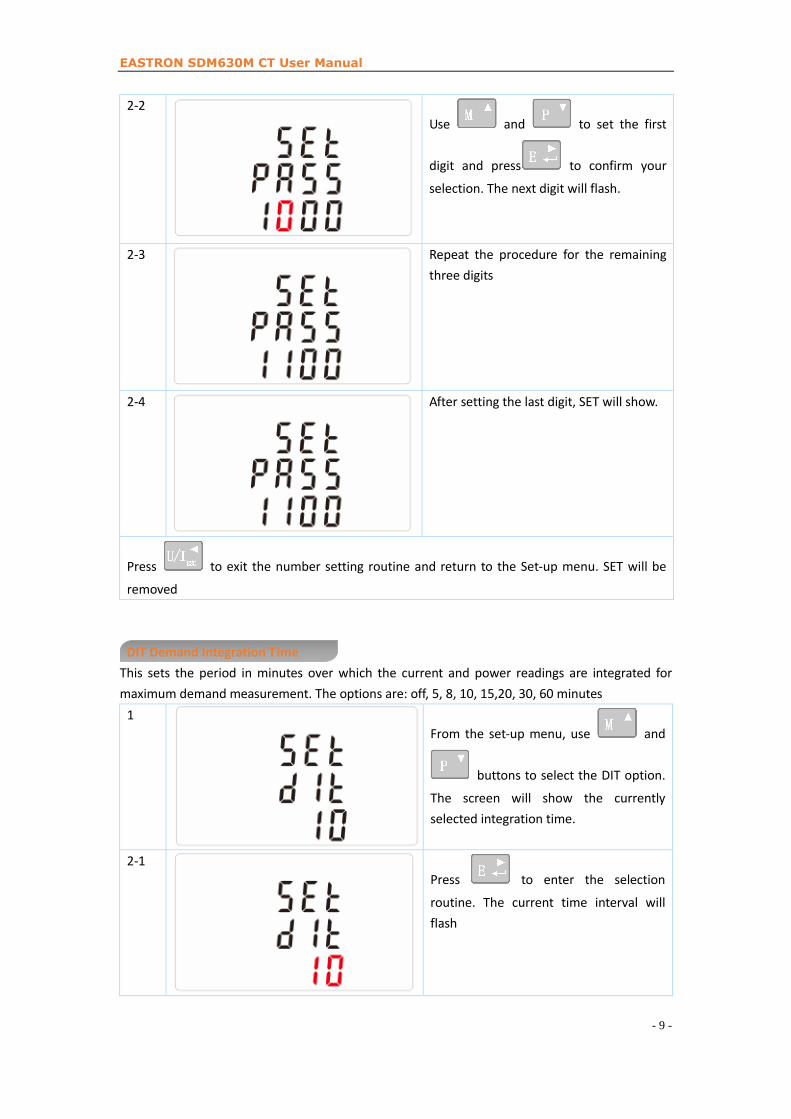
2-2
Use and to set the first
digit and press to confirm your
selection. The next digit will flash.
2-3 Repeat the procedure for the remaining
three digits
2-4 After setting the last digit, SET will show.
Press to exit the number setting routine and return to the Set-up menu. SET will be
removed
DIT Demand Integration Time
This sets the period in minutes over which the current and power readings are integrated for
maximum demand measurement. The options are: off, 5, 8, 10, 15,20, 30, 60 minutes
1
From the set-up menu, use and
buttons to select the DIT option.
The screen will show the currently
selected integration time.
2-1
Press to enter the selection
routine. The current time interval will
flash

EASTRON SDM630M CT User Manual
- 10 -
2-2
Use and to select the time
required.
2-3
Press to confirm the selection.
SET indicator will appear.
Press to exit the DIT selection routine and return to the menu.
Backlit set-up
The meter provides a function to set the blue backlit lasting time.
1 The backlit lasting time is settable
Default lasting time is 60minutes
For example, if it’s set as 5, the backlit
will be off in 5minutes from the last time
operation on the meter.
Notes: If it’s set as 0, the backlit will
always be on.
2
Press to enter the selection
routine. The current time interval will
flash
The options can be:
0/5/10/30/60/120minutes
Use and buttons to select the time required. Then press to confirm
the set-up,
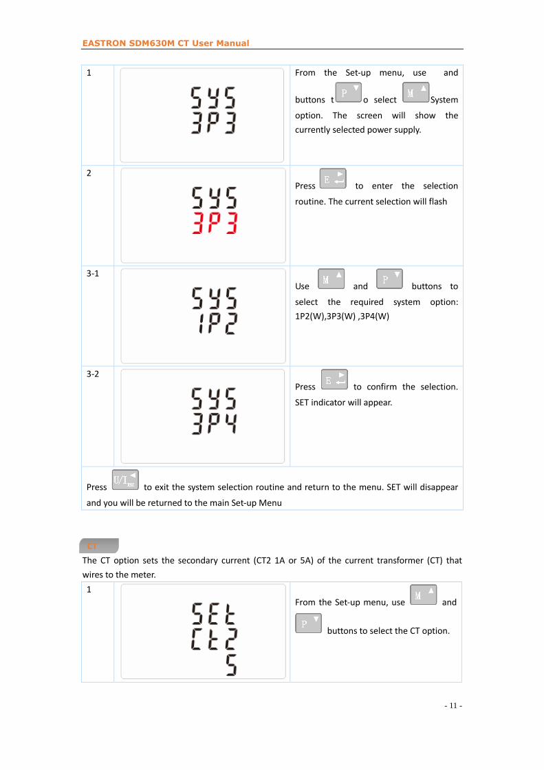
Supply System
Use this section to set the type of power supply being monitored.
EASTRON SDM630M CT User Manual
- 11 -
1 From the Set-up menu, use and
buttons t o select System
option. The screen will show the
currently selected power supply.
2
Press to enter the selection
routine. The current selection will flash
3-1
Use and buttons to
select the required system option:
1P2(W),3P3(W) ,3P4(W)
3-2
Press to confirm the selection.
SET indicator will appear.
Press to exit the system selection routine and return to the menu. SET will disappear
and you will be returned to the main Set-up Menu
CT
The CT option sets the secondary current (CT2 1A or 5A) of the current transformer (CT) that
wires to the meter.
1
From the Set-up menu, use and
buttons to select the CT option.
EASTRON SDM630M CT User Manual
- 12 -
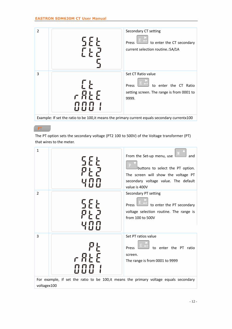
2 Secondary CT setting
Press to enter the CT secondary
current selection routine.:5A/1A
3 Set CT Ratio value
Press to enter the CT Ratio
setting screen. The range is from 0001 to
9999.
Example: If set the ratio to be 100,it means the primary current equals secondary currentx100
The PT option sets the secondary voltage (PT2 100 to 500V) of the Voltage transformer (PT)
that wires to the meter.
1
From the Set-up menu, use and
buttons to select the PT option.
The screen will show the voltage PT
secondary voltage value. The default
value is 400V
2 Secondary PT setting
Press to enter the PT secondary
voltage selection routine. The range is
from 100 to 500V
3 Set PT ratios value
Press to enter the PT ratio
screen.
The range is from 0001 to 9999
For example, if set the ratio to be 100,it means the primary voltage equals secondary
voltagex100
PT
EASTRON SDM630M CT User Manual
- 13 -
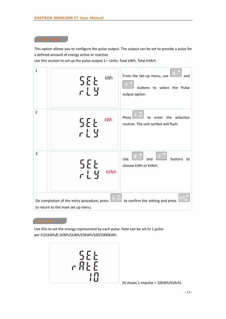
This option allows you to configure the pulse output. The output can be set to provide a pulse for
a defined amount of energy active or reactive.
Use this section to set up the pulse output 1—Units: Total kWh, Total kVArh
1
From the Set-up menu, use and
buttons to select the Pulse
output option.
2
Press to enter the selection
routine. The unit symbol will flash.
3
Use and buttons to
choose kWh or kVArh.
to confirm the setting and press
Use this to set the energy represented by each pulse. Rate can be set to 1 pulse
per 0.01kWh/0.1kWh/1kWh/10kWh/100/1000kWh.
(It shows 1 impulse = 10kWh/kVArh)
Pulse rate
On completion of the entry procedure, press
to return to the main set up menu.
Pulse output
EASTRON SDM630M CT User Manual
- 14 -
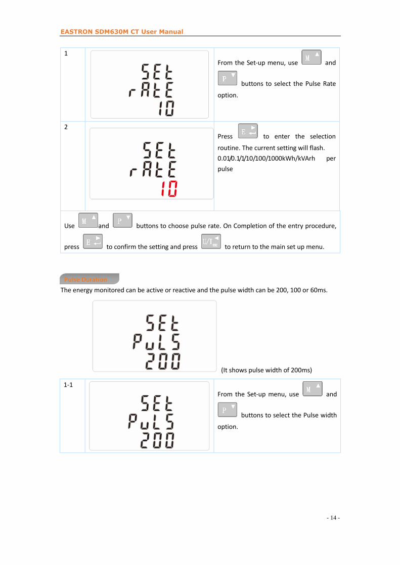
1
From the Set-up menu, use and
buttons to select the Pulse Rate
option.
2
Press to enter the selection
routine. The current setting will flash.
0.01/0.1/1/10/100/1000kWh/kVArh per
pulse
Use and buttons to choose pulse rate. On Completion of the entry procedure,
press to confirm the setting and press to return to the main set up menu.
Pulse Duration
The energy monitored can be active or reactive and the pulse width can be 200, 100 or 60ms.
(It shows pulse width of 200ms)
1-1
From the Set-up menu, use and
buttons to select the Pulse width
option.

EASTRON SDM630M CT User Manual
- 15 -
1-2
Press to enter the selection
routine. The current setting will flash.
Use and buttons to
choose pulse width.
On completion of the entry procedure, press to confirm the setting and press
to return to the main set up menu.
Communication
There is a Mbus port can be used for communication using Mbus protocol. For Mbus
communication, parameters are selected from Front panel.
Mbus Address
1
From the Set-up menu, use and
buttons to select the first
Address
2-1
Press button to enter the
selection routine. The current setting
will be flashing.
2-2
Use and buttons to
choose the first Address(001 to 247)

EASTRON SDM630M CT User Manual
- 16 -
3 Mbus secondary address
It ranges from 00 00 00 01 to 99 99 99 99
On completion of the entry procedure, press button to confirm the setting and press
button to return the main set-up menu.
Baud Rate
1
From the Set-up menu, use and
buttons to select the Baud Rate
option.
2-1
Press to enter the selection
routine. The current setting will flash.
2-2
Use and buttons to
choose Baud rate 2.4k. 4.8k, 9.6k, 19.2k,
38.4k
On completion of the entry procedure, press to confirm the setting and press
to return to the main set up menu.
Parity

EASTRON SDM630M CT User Manual
- 17 -
1
From the Set-up menu, use and
buttons to select the Parity
option.
2-1
Press to enter the selection
routine. The current setting will flash.
2-2
Use and buttons to
choose Parity (EVEN / ODD/ NONE)
Default is NONE.
On completion of the entry procedure, press to confirm the setting and press
to return to the main set up menu.
Stop bits
1
From the Set-up menu, use and
buttons to select the Stop Bit
option.
2-1
Press to enter the selection
routine. The current setting will flash.

EASTRON SDM630M CT User Manual
- 18 -
2-2
Use and buttons to
choose Stop Bit (2 or 1)
On completion of the entry procedure, press to confirm the setting and press
to return to the main set up menu.
Note: Default is 1, and only when the parity is NONE that the stop bit can be changed to 2.
CLR
The meter provides a function to reset the maximum demand value of current and power.
1
From the Set-up menu, use and
buttons to select the reset
option.
2
Press to enter the selection
routine. The MD will flash.
Press to confirm the setting and press to return to the main set up menu.
Reverse connected current inputs correction set-up
1
use and buttons to
select page “SET sys cont”

EASTRON SDM630M CT User Manual
- 19 -
2-1
Press to enter Phase A , the
default is Frd (forward)
2-2
use and buttons to
Phase B or C setting pages
How to operate if phase A is reversely connected
1 Go to phase A setting page
2
Press to enter the selection
routine. The Frd will flash.
Use button to change Frd to Rev.
Press to confirm the setting and press to return to the main set up menu.
Specifications
Measured Parameters
The unit can monitor and display the following parameters of a single phase two wire(1p2w),
three phase three wire(3p3w) or four phase four wire(3p4w) supply.
Voltage and Current
Phase to neutral voltages 100 to 275V a.c. (not for 3p3w supplies)
Voltages between phases 173 to 480V a.c. (3p supplies only)

EASTRON SDM630M CT User Manual
- 20 -
Percentage total voltage harmonic distortion (THD%) for each phase to N ( not for 3p3w supplies)
Percentage voltage THD% between phases (three phase supplies only)
Current THD% for each phase
Power factor and Frequency and Max. Demand
Frequency in 50-60 Hz
Instantaneous power:
Power 0 to 3600 MW
Reactive Power 0 to 3600 MVAr
Volt-amps 0 to 3600 MVA
Maximum demanded power since last Demand reset Power factor
Maximum neutral demand current, since the last Demand reset (for three phase supplies only)
Energy Measurements
Imported/Exported active energy 0 to 9999999.9 kWh
Imported/Exported reactive energy 0 to 9999999.9 kVArh
Total active energy 0 to 9999999.9 kWh
Total reactive energy 0 to 9999999.9 kVArh
Measured Inputs
Voltage inputs through 4-way fixed connector with 2.5mm² stranded wire capacity. single phase
two wire(1p2w), three phase three wire(3p3w) or four phase four wire(3p4w) unbalanced. Line
frequency measured from L1 voltage or L3 voltage.
Three current inputs (six physical terminals) with 2.5mm² stranded wire capacity for connection
of external CTs. Nominal rated input current 5A or 1A a.c. Rms.
Accuracy
Voltage ±0·5% of range maximum
Current ±0·5% of nominal
Frequency ±0·2% of mid-frequency
Power factor ±1% of unity (0.01)
Active power (W) ±1% of range maximum
Reactive power (VAr) ±1% of range maximum
Apparent power (VA) ±1% of range maximum
Active energy (Wh) Class 1 IEC 62053-21
Reactive energy (VARh) ±1% of range maximum
Total harmonic distortion ±1% up to 31st harmonic
Response time to step input 1s, typical, to >99% of final reading, at 50 Hz.
*Auxiliary Supply
Two-way fixed connector with 2·5mm2 stranded wire capacity.
85 to 275V a.c. 50/60Hz ±10% or 120V to 380V d.c. ±20%. Consumption < 10W.
Interfaces for External Monitoring
EASTRON SDM630M CT User Manual
- 21 -
Three interfaces are provided:
an MBus communication channel that can be programmed for MBus EN13757-3 protocol
an output indicating real-time measured energy.(configurable)
an pulse output 3200imp/kWh (not configurable)
The Mbus configuration (Baud rate etc.) and the pulse output assignments (kW/kVArh) are
configured through the Set-up screens.
Pulse Output
The unit provides two pulse outputs. Both pulse outputs are passive type.
Pulse output 1 is configurable. The pulse output can be set to generate pulses to represent total
kWh or kVarh.
The pulse constant can be set to generate 1 pulse per:
0.01 = 10 Wh/VArh
0.1 = 100 Wh/VArh
1 = 1 kWh/kVArh
10 = 10 kWh/kVArh
100 = 100 kWh/kVArh
1000=1000 kWh/kVArh
Pulse width: 200/100(default)/60ms
Pulse output 2 is non-configurable. It is fixed up with total kWh. The constant is 3200imp/kWh.
MBus Output for EN_13757-3
For MBus EN13757-3, the following MBus communication parameters can be configured from the
Set-up menu:
Baud rate 300, 600, 1200, 2400, 4800, 9600
Parity none (default)/odd/even
Stop bits 1 or 2
MBus network primary address nnn – 3-digit number, 001 to 250
MBus network secondary address 00 00 00 01 to 99 99 99 99(The secondary address can
not be setted directly on meter, but can be done via Mbus communication)
Reference Conditions of Influence Quantities
Influence Quantities are variables that affect measurement errors to a minor degree. Accuracy is
verified under nominal value (within the specified tolerance) of these conditions.
Ambient temperature 23°C ±1°C
Input frequency 50 or 60Hz ±2%
Input waveform Sinusoidal (distortion factor < 0·005)
Auxiliary supply voltage Nominal ±1%
Auxiliary supply frequency Nominal ±1%
Auxiliary supply waveform (if AC) Sinusoidal (distortion factor < 0·05)
Magnetic field of external origin Terrestrial flux
Environment
Operating temperature -25°C to +55°C*

EASTRON SDM630M CT User Manual
- 22 -
Storage temperature -40°C to +70°C*
Relative humidity 0 to 90%, non-condensing
Altitude Up to 2000m
Warm up time 1 minute
Vibration 10Hz to 50Hz, IEC 60068-2-6, 2g
Shock 30g in 3 planes
Dimensions
EASTRON SDM630M CT User Manual
- 23 -
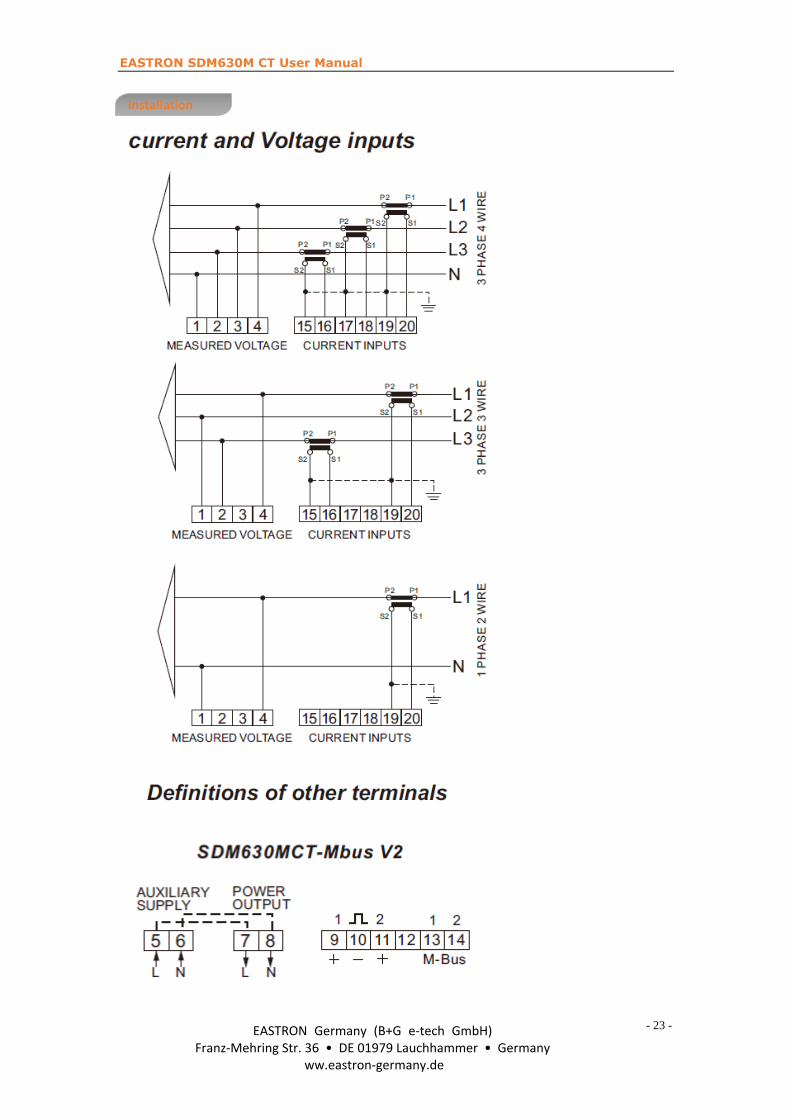
Installation
EASTRON Germany (B+G e-tech GmbH)Franz-Mehring Str. 36 • DE 01979 Lauchhammer • Germany
ww.eastron-germany.de

1
SDM630 MBUS protocol V1.1 1. Initialization slave Format:
Start C Field A Field Check Sum Stop
10 40 XX CS 16
XX=1 to FF The address field serves to address the recipient in the calling direction, and to identify the sender of information in the receiving direction. The size of this field is one Byte, and can therefore take values from 0 to 255. The addresses 1 to 250 can be allocated to the individual slaves, up to a maximum of 250.Unconfigured slaves are given the address 0 at manufacture, and as a rule are allocated one of these addresses when connected to the M-Bus. The addresses254 (FE) and 255 (FF) are used to transmit information to all participants (Broadcast). With address 255 none of the slaves reply, and with address 254 all slaves reply with their own addresses. The latter case naturally results in collisions when two or more slaves are connected, and should only be used for test purposes. The address 253 (FD) indicates that the addressing has been performed in the Network Layer instead of Data Link Layer, The FD used when using The second level address. The remaining addresses 251 and 252 have been kept for future applications. 1.1 How to initialize a meter which you don’t know the address Master to slave: 10 40 fe 3e 16 Slave to master:e5 (success) 1.2 Remove the secondary address matching symbol of all the meters on BUS. Master to slave: 10 40 fd 3d 16 Slave: No answer
1.3 How to initialize all meters on the bus line by using FF as broadcast address Master to slave: 10 40 ff 3f 16 Slave: No answer 1.4 How to Initialize a Slave with specific address Example: Address 01 Master to slave : 10 40 01 41 16 Slave to master: e5 2. How to Set Baut rate 2.1 Point to point baud-rate setting command format (Control Frame)
Start L Field L Field Start C Field A Field CI Field Check Sum Stop
68H 03 03 68H 53/73 Addr b8~bd CS 16
L Field------Byte length C Field--------Control Field, Function Field A Field --------Address Field
2
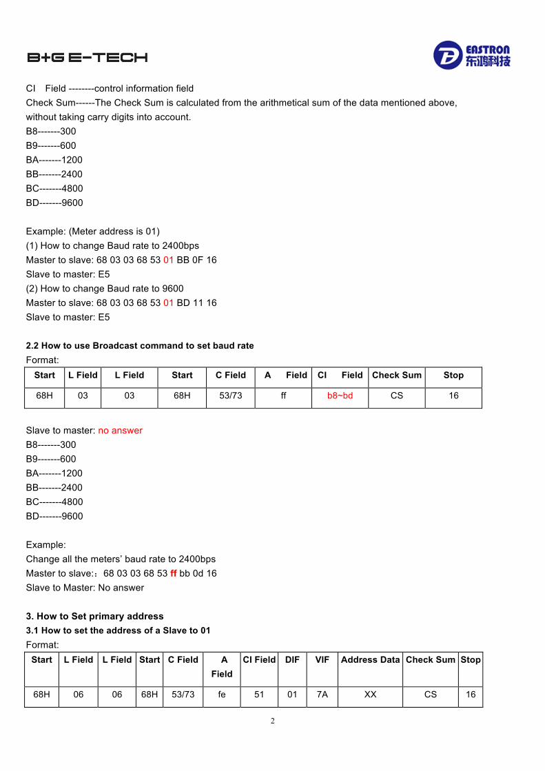
CI Field --------control information field Check Sum------The Check Sum is calculated from the arithmetical sum of the data mentioned above, without taking carry digits into account. B8-------300 B9-------600 BA-------1200 BB-------2400 BC-------4800 BD-------9600 Example: (Meter address is 01) (1) How to change Baud rate to 2400bps Master to slave: 68 03 03 68 53 01 BB 0F 16 Slave to master: E5 (2) How to change Baud rate to 9600 Master to slave: 68 03 03 68 53 01 BD 11 16 Slave to master: E5 2.2 How to use Broadcast command to set baud rate Format:
Start L Field L Field Start C Field A Field CI Field Check Sum Stop
68H 03 03 68H 53/73 ff b8~bd CS 16
Slave to master: no answer B8-------300 B9-------600 BA-------1200 BB-------2400 BC-------4800 BD-------9600 Example: Change all the meters’ baud rate to 2400bps Master to slave::68 03 03 68 53 ff bb 0d 16 Slave to Master: No answer 3. How to Set primary address 3.1 How to set the address of a Slave to 01 Format:
Start L Field L Field Start C Field A Field
CI Field DIF VIF Address Data Check Sum Stop
68H 06 06 68H 53/73 fe 51 01 7A XX CS 16
3
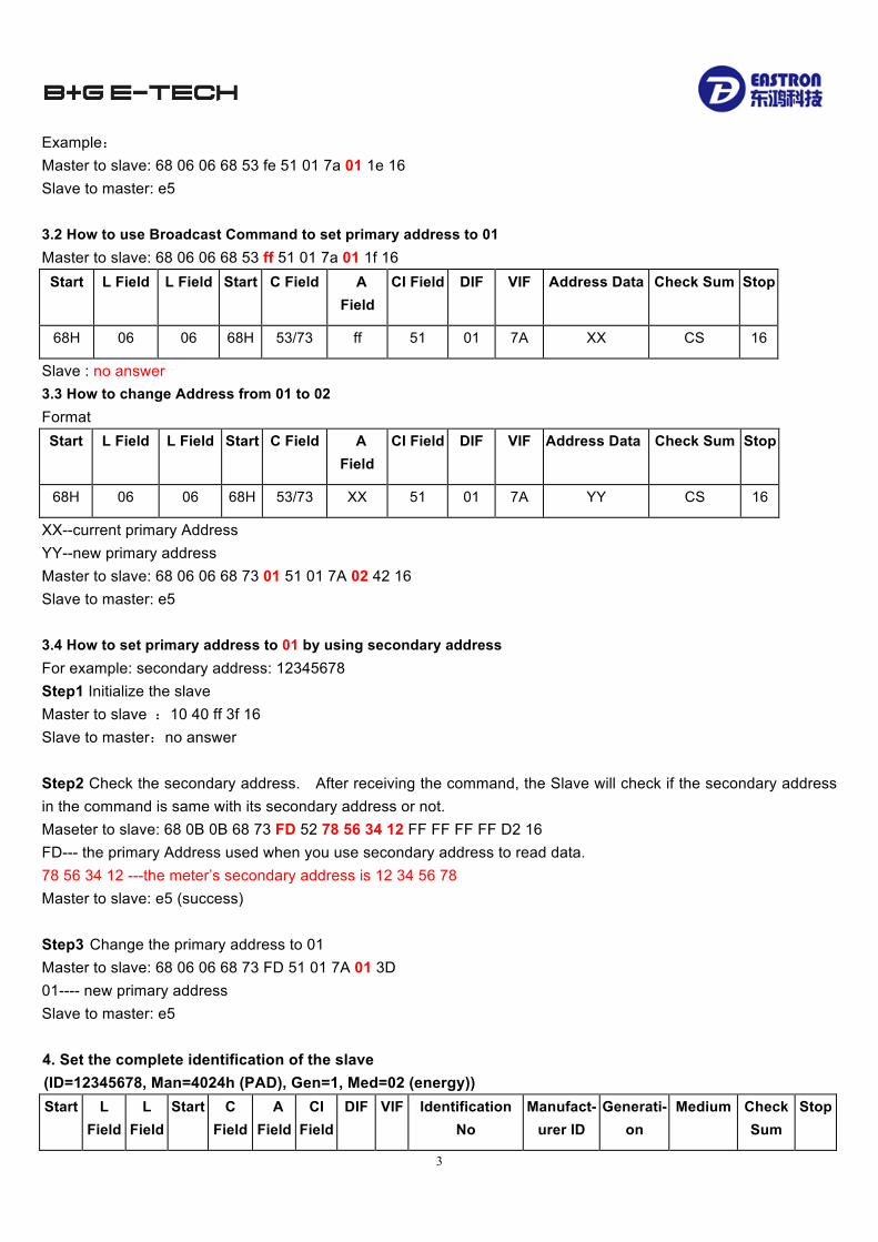
Example: Master to slave: 68 06 06 68 53 fe 51 01 7a 01 1e 16 Slave to master: e5
3.2 How to use Broadcast Command to set primary address to 01 Master to slave: 68 06 06 68 53 ff 51 01 7a 01 1f 16
Start L Field L Field Start C Field A Field
CI Field DIF VIF Address Data Check Sum Stop
68H 06 06 68H 53/73 ff 51 01 7A XX CS 16
Slave : no answer 3.3 How to change Address from 01 to 02 Format Start L Field L Field Start C Field A
Field CI Field DIF VIF Address Data Check Sum Stop
68H 06 06 68H 53/73 XX 51 01 7A YY CS 16
XX--current primary Address YY--new primary address Master to slave: 68 06 06 68 73 01 51 01 7A 02 42 16 Slave to master: e5 3.4 How to set primary address to 01 by using secondary address For example: secondary address: 12345678 Step1 Initialize the slave Master to slave :10 40 ff 3f 16 Slave to master:no answer
Step2 Check the secondary address. After receiving the command, the Slave will check if the secondary address in the command is same with its secondary address or not. Maseter to slave: 68 0B 0B 68 73 FD 52 78 56 34 12 FF FF FF FF D2 16 FD--- the primary Address used when you use secondary address to read data. 78 56 34 12 ---the meter’s secondary address is 12 34 56 78 Master to slave: e5 (success) Step3 Change the primary address to 01 Master to slave: 68 06 06 68 73 FD 51 01 7A 01 3D 01---- new primary address Slave to master: e5
4. Set the complete identification of the slave (ID=12345678, Man=4024h (PAD), Gen=1, Med=02 (energy))
Start L Field
L Field
Start C Field
A Field
CI Field
DIF VIF Identification No
Manufact-urer ID
Generati-on
Medium Check Sum
Stop
4
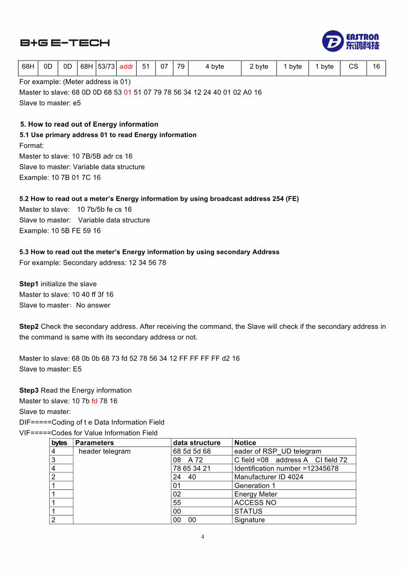
68H 0D 0D 68H 53/73 addr 51 07 79 4 byte 2 byte 1 byte 1 byte CS 16
For example: (Meter address is 01) Master to slave: 68 0D 0D 68 53 01 51 07 79 78 56 34 12 24 40 01 02 A0 16 Slave to master: e5
5. How to read out of Energy information 5.1 Use primary address 01 to read Energy information
Format: Master to slave: 10 7B/5B adr cs 16 Slave to master: Variable data structure Example: 10 7B 01 7C 16 5.2 How to read out a meter’s Energy information by using broadcast address 254 (FE) Master to slave: 10 7b/5b fe cs 16 Slave to master: Variable data structure Example: 10 5B FE 59 16 5.3 How to read out the meter’s Energy information by using secondary Address For example: Secondary address: 12 34 56 78 Step1 initialize the slave Master to slave: 10 40 ff 3f 16 Slave to master:No answer Step2 Check the secondary address. After receiving the command, the Slave will check if the secondary address in the command is same with its secondary address or not. Master to slave: 68 0b 0b 68 73 fd 52 78 56 34 12 FF FF FF FF d2 16 Slave to master: E5
Step3 Read the Energy information Master to slave: 10 7b fd 78 16 Slave to master: DIF=====Coding of t e Data Information Field VIF=====Codes for Value Information Field
bytes Parameters data structure Notice 4 header telegram 68 5d 5d 68 eader of RSP_UD telegram 3 08 A 72 C field =08 address A CI field 72 4 78 65 34 21 Identification number =12345678 2 24 40 Manufacturer ID 4024 1 01 Generation 1 1 02 Energy Meter 1 55 ACCESS NO 1 00 STATUS 2 00 00 Signature
5
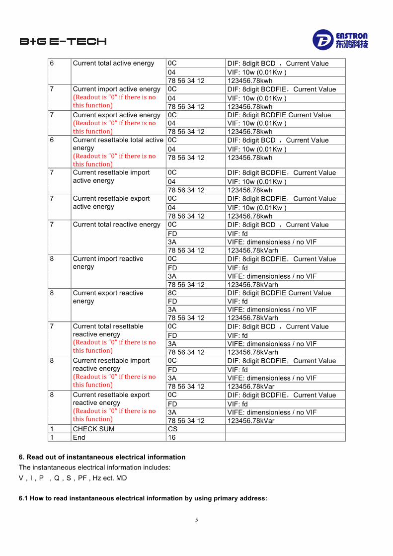
6 Current total active energy
0C DIF: 8digit BCD ,Current Value 04 VIF: 10w (0.01Kw ) 78 56 34 12 123456.78kwh
7 Current import active energy (Readoutis“0”ifthereisnothisfunction)
0C DIF: 8digit BCDFIE,Current Value 04 VIF: 10w (0.01Kw ) 78 56 34 12 123456.78kwh
7 Current export active energy (Readoutis“0”ifthereisnothisfunction)
0C DIF: 8digit BCDFIE Current Value 04 VIF: 10w (0.01Kw ) 78 56 34 12 123456.78kwh
6 Current resettable total active energy (Readoutis“0”ifthereisnothisfunction)
0C DIF: 8digit BCD ,Current Value 04 VIF: 10w (0.01Kw ) 78 56 34 12 123456.78kwh
7
Current resettable import active energy
0C DIF: 8digit BCDFIE,Current Value 04 VIF: 10w (0.01Kw ) 78 56 34 12 123456.78kwh
7 Current resettable export active energy
0C DIF: 8digit BCDFIE,Current Value 04 VIF: 10w (0.01Kw ) 78 56 34 12 123456.78kwh
7 Current total reactive energy 0C DIF: 8digit BCD ,Current Value FD VIF: fd 3A VIFE: dimensionless / no VIF 78 56 34 12 123456.78kVarh
8 Current import reactive energy
0C DIF: 8digit BCDFIE,Current Value FD VIF: fd 3A VIFE: dimensionless / no VIF 78 56 34 12 123456.78kVarh
8 Current export reactive energy
8C DIF: 8digit BCDFIE Current Value FD VIF: fd 3A VIFE: dimensionless / no VIF 78 56 34 12 123456.78kVarh
7 Current total resettable reactive energy (Readoutis“0”ifthereisnothisfunction)
0C DIF: 8digit BCD ,Current Value FD VIF: fd 3A VIFE: dimensionless / no VIF 78 56 34 12 123456.78kVarh
8 Current resettable import reactive energy (Readoutis“0”ifthereisnothisfunction)
0C DIF: 8digit BCDFIE,Current Value FD VIF: fd 3A VIFE: dimensionless / no VIF 78 56 34 12 123456.78kVar
8 Current resettable export reactive energy (Readoutis“0”ifthereisnothisfunction)
0C DIF: 8digit BCDFIE,Current Value FD VIF: fd 3A VIFE: dimensionless / no VIF 78 56 34 12 123456.78kVar
1 CHECK SUM CS 1 End 16
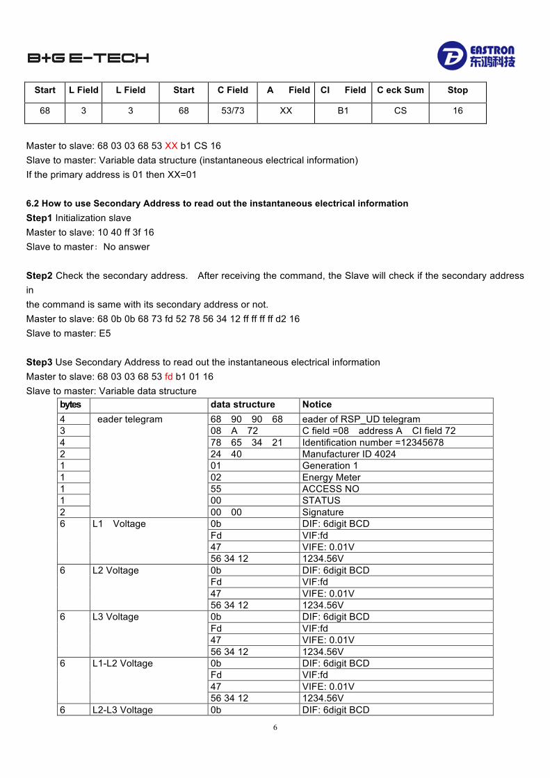
6. Read out of instantaneous electrical information The instantaneous electrical information includes: V,I,P ,Q,S,PF , Hz ect. MD 6.1 How to read instantaneous electrical information by using primary address:
6
Start L Field L Field Start C Field A Field CI Field C eck Sum Stop
68 3 3 68 53/73 XX B1 CS 16
Master to slave: 68 03 03 68 53 XX b1 CS 16 Slave to master: Variable data structure (instantaneous electrical information) If the primary address is 01 then XX=01 6.2 How to use Secondary Address to read out the instantaneous electrical information Step1 Initialization slave Master to slave: 10 40 ff 3f 16 Slave to master:No answer
Step2 Check the secondary address. After receiving the command, the Slave will check if the secondary address in the command is same with its secondary address or not. Master to slave: 68 0b 0b 68 73 fd 52 78 56 34 12 ff ff ff ff d2 16 Slave to master: E5
Step3 Use Secondary Address to read out the instantaneous electrical information Master to slave: 68 03 03 68 53 fd b1 01 16 Slave to master: Variable data structure
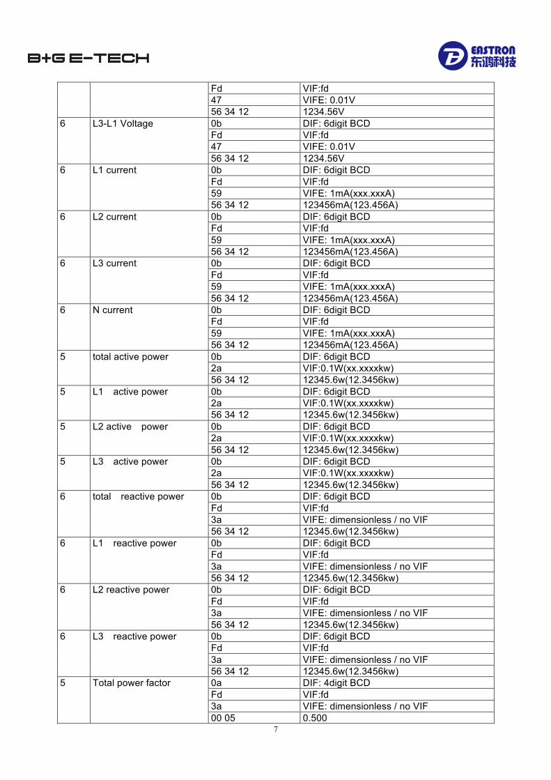
bytes data structure Notice 4 eader telegram 68 90 90 68 eader of RSP_UD telegram 3 08 A 72 C field =08 address A CI field 72 4 78 65 34 21 Identification number =12345678 2 24 40 Manufacturer ID 4024 1 01 Generation 1 1 02 Energy Meter 1 55 ACCESS NO 1 00 STATUS 2 00 00 Signature 6 L1 Voltage 0b DIF: 6digit BCD
Fd VIF:fd 47 VIFE: 0.01V 56 34 12 1234.56V
6 L2 Voltage 0b DIF: 6digit BCD Fd VIF:fd 47 VIFE: 0.01V 56 34 12 1234.56V
6 L3 Voltage 0b DIF: 6digit BCD Fd VIF:fd 47 VIFE: 0.01V 56 34 12 1234.56V
6 L1-L2 Voltage 0b DIF: 6digit BCD Fd VIF:fd 47 VIFE: 0.01V 56 34 12 1234.56V
6 L2-L3 Voltage 0b DIF: 6digit BCD
7
Fd VIF:fd 47 VIFE: 0.01V 56 34 12 1234.56V
6 L3-L1 Voltage 0b DIF: 6digit BCD Fd VIF:fd 47 VIFE: 0.01V 56 34 12 1234.56V
6 L1 current 0b DIF: 6digit BCD Fd VIF:fd 59 VIFE: 1mA(xxx.xxxA) 56 34 12 123456mA(123.456A)
6 L2 current 0b DIF: 6digit BCD Fd VIF:fd 59 VIFE: 1mA(xxx.xxxA) 56 34 12 123456mA(123.456A)
6 L3 current 0b DIF: 6digit BCD Fd VIF:fd 59 VIFE: 1mA(xxx.xxxA) 56 34 12 123456mA(123.456A)
6
N current
0b DIF: 6digit BCD Fd VIF:fd 59 VIFE: 1mA(xxx.xxxA) 56 34 12 123456mA(123.456A)
5 total active power 0b DIF: 6digit BCD 2a VIF:0.1W(xx.xxxxkw) 56 34 12 12345.6w(12.3456kw)
5 L1 active power 0b DIF: 6digit BCD 2a VIF:0.1W(xx.xxxxkw) 56 34 12 12345.6w(12.3456kw)
5 L2 active power 0b DIF: 6digit BCD 2a VIF:0.1W(xx.xxxxkw) 56 34 12 12345.6w(12.3456kw)
5 L3 active power 0b DIF: 6digit BCD 2a VIF:0.1W(xx.xxxxkw) 56 34 12 12345.6w(12.3456kw)
6 total reactive power 0b DIF: 6digit BCD Fd VIF:fd 3a VIFE: dimensionless / no VIF 56 34 12 12345.6w(12.3456kw)
6 L1 reactive power 0b DIF: 6digit BCD Fd VIF:fd 3a VIFE: dimensionless / no VIF 56 34 12 12345.6w(12.3456kw)
6 L2 reactive power 0b DIF: 6digit BCD Fd VIF:fd 3a VIFE: dimensionless / no VIF 56 34 12 12345.6w(12.3456kw)
6 L3 reactive power 0b DIF: 6digit BCD Fd VIF:fd 3a VIFE: dimensionless / no VIF 56 34 12 12345.6w(12.3456kw)
5 Total power factor 0a DIF: 4digit BCD Fd VIF:fd 3a VIFE: dimensionless / no VIF 00 05 0.500

8
5 A power factor 0a DIF: 4digit BCD Fd VIF:fd 3a VIFE: dimensionless / no VIF 00 05 0.500
5 B power factor 0a DIF: 4digit BCD Fd VIF:fd 3a VIFE: dimensionless / no VIF 00 05 0.500
5 C power factor 0a DIF: 4digit BCD Fd VIF:fd 3a VIFE: dimensionless / no VIF 00 05 0.500
5 Frequency 0a DIF: 4digit BCD Fd VIF:fd 3a VIFE: dimensionless / no VIF 00 50 50.00 z
1 End CS 1 16
7. How to read password
Start L Field L Field Start C Field A Field CI Field C eck Sum Stop
68 3 3 68 11 addr 03 CS 16
Master to Slave:68 03 03 68 11 addr 03 cs 16 Slave to Master:68 05 05 68 11 addr 03 password H password L cs 16 7.1 Change to a new Password
Start L Field
L Field Start C Field A Field CI Field Data C eck Sum Stop
68 5 5 68 11 addr 04 Password Password L CS 16
Master to Slave:68 05 05 68 11 addr 04 password H password L cs 16 Slave to Master:E5 8. How to reset all resettable energy data
Start L Field L Field Start C Field A Field CI Field C eck Sum Stop
68 3 3 68 11 addr 0d CS 16
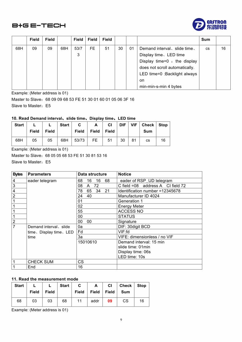
For example: addr: 01 Master to Slave:68 03 03 68 11 01 0d 1f 16 Slave to Master:e5 9. Set Demand interval、slide time、Display time、LED time Send:68 09 09 68 53 FE 51 30 01 60 01 05 06 3F 16
Start L L Start C A CI DIF VIF data Check Stop
9
Field Field Field Field Field Sum
68H 09 09 68H 53/73
FE 51 30 01 Demand interval、slide time、Display time、LED time Display time=0 :the display does not scroll automatically. LED time=0 :Backlight always on min-min-s-min 4 bytes
cs 16
Example: (Meter address is 01)Master to Slave:68 09 09 68 53 FE 51 30 01 60 01 05 06 3F 16 Slave to Master:E5 10. Read Demand interval、slide time、Display time、LED time
Start L Field
L Field
Start C Field
A Field
CI Field
DIF VIF Check Sum
Stop
68H 05 05 68H 53/73 FE 51 30 81 cs 16
Example: (Meter address is 01) Master to Slave:68 05 05 68 53 FE 51 30 81 53 16 Slave to Master:E5 Bytes Parameters Data structure Notice 4 eader telegram 68 16 16 68 eader of RSP_UD telegram 3 08 A 72 C field =08 address A CI field 72 4 78 65 34 21 Identification number =12345678 2 24 40 Manufacturer ID 4024 1 01 Generation 1 1 02 Energy Meter 1 55 ACCESS NO 1 00 STATUS 2 00 00 Signature 7 Demand interval、slide
time、Display time、LED time
0a DIF: 30digit BCD Fd VIF:fd 3a VIFE: dimensionless / no VIF 15010610 Demand interval: 15 min
slide time: 01min Display time: 06s LED time: 10s
1 CHECK SUM CS 1 End 16
11. Read the measurement mode
Start L Field
L Field
Start C Field
A Field
CI Field
Check Sum
Stop
68 03 03 68 11 addr 09 CS 16
Example: (Meter address is 01)

10
Master to Slave: 68 03 03 68 11 01 09 1b 16 Slave to Master: 68 04 04 68 11 01 09 01 1c 16 The red-lighted 01 represents the measurement mode 01means Active energy 02means Active energy+Reactive energy 03emans Active energy- Reactive energy 12. Set up the measurement mode
Start L Field L Field Start C Field A Field
CI Field
data Check Sum
Stop
68 04 04 68 11 addr 0A 01/02/03 CS 16
Example: (Meter address is 01) Master to Slave: 68 04 04 68 11 01 0A 01 1c 16 Slave to Master: e5 The red-lighted 01 represents the measurement mode 01 means Active energy 02 means Active energy+Reactive energy 03 means Active energy- Reactive energy 13. Read the output mode of Pulse 1
Start L Field
L Field
Start C Field
A Field
CI Field
Check Sum
Stop
68 03 03 68 11 addr 10 CS 16
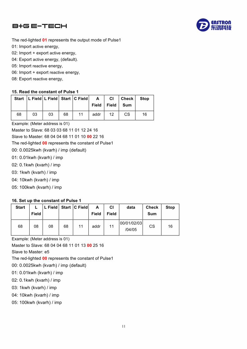
Example: (Meter address is 01) Master to Slave: 68 03 03 68 11 01 10 22 16 Slave to Master: 68 04 04 68 11 01 10 01 23 16 The red-lighted 01 represents the output mode of Pulse1 01: Import active energy, 02: Import + export active energy, 04: Export active energy (default). 05: Import reactive energy, 06: Import + export reactive energy, 08: Export reactive energy, 14. Set up the output mode of Pulse 1
Start L Field L Field Start C Field A Field
CI Field
data Check Sum
Stop
68 08 08 68 11 addr 11 01/02/04/05/06/08 CS 16
Example: (Meter address is 01) Master to Slave: 68 04 04 68 11 01 11 01 24 16 Slave to Master: e5
11
The red-lighted 01 represents the output mode of Pulse1 01: Import active energy, 02: Import + export active energy, 04: Export active energy, (default). 05: Import reactive energy, 06: Import + export reactive energy, 08: Export reactive energy, 15. Read the constant of Pulse 1
Start L Field L Field Start C Field A Field
CI Field
Check Sum
Stop
68 03 03 68 11 addr 12 CS 16
Example: (Meter address is 01) Master to Slave: 68 03 03 68 11 01 12 24 16 Slave to Master: 68 04 04 68 11 01 10 00 22 16 The red-lighted 00 represents the constant of Pulse1 00: 0.0025kwh (kvarh) / imp (default)
01: 0.01kwh (kvarh) / imp 02: 0.1kwh (kvarh) / imp
03: 1kwh (kvarh) / imp
04: 10kwh (kvarh) / imp
05: 100kwh (kvarh) / imp 16. Set up the constant of Pulse 1
Start L Field
L Field Start C Field A Field
CI Field
data Check Sum
Stop
68 08 08 68 11 addr 11 00/01/02/03
/04/05 CS 16
Example: (Meter address is 01) Master to Slave: 68 04 04 68 11 01 13 00 25 16 Slave to Master: e5 The red-lighted 00 represents the constant of Pulse1 00: 0.0025kwh (kvarh) / imp (default) 01: 0.01kwh (kvarh) / imp
02: 0.1kwh (kvarh) / imp
03: 1kwh (kvarh) / imp
04: 10kwh (kvarh) / imp 05: 100kwh (kvarh) / imp

12
Distributed by: B+G e-tech GmbH Franz-Mehring Str. 36 DE 01979 Lauchhammer T: +49 3574 46755 0 F: +49 3574 46755 19 M: [email protected] W: www.bg-etech.de