Sdac Lec 9 10 Space Propulsion
239
IN THE NAME OF ALLAH THE MOST BENEFICENT THE MOST MERCIFUL
-
Upload
muhammad-ishaq-khan -
Category
Documents
-
view
221 -
download
0
Transcript of Sdac Lec 9 10 Space Propulsion

8/23/2019 Sdac Lec 9 10 Space Propulsion
http://slidepdf.com/reader/full/sdac-lec-9-10-space-propulsion 1/239
IN THE NAME OFALLAH
THE MOST BENEFICENT
THE MOST MERCIFUL

8/23/2019 Sdac Lec 9 10 Space Propulsion
http://slidepdf.com/reader/full/sdac-lec-9-10-space-propulsion 2/239
SPACERAFTDYNAMICS AND CONTROL

8/23/2019 Sdac Lec 9 10 Space Propulsion
http://slidepdf.com/reader/full/sdac-lec-9-10-space-propulsion 3/239
[email protected] ; 0321-9595510
DR. QASIM ZEESHANBE, MECHANICAL ENGINEERING
NATIONAL UNIVERSITY OF SCIENCE AND TECHNOLOGY, NUST, PAKISTAN, 2000
MS, FLIGHT VEHICLE DESIGNBEIJING UNIVERSITY OF AERONAUTICS AND ASTRONAUTICS, BUAA, P.R.CHINA, 2006
PhD, FLIGHT VEHICLE DESIGNBEIJING UNIVERSITY OF AERONAUTICS AND ASTRONAUTICS, BUAA, P.R.CHINA, 2009
8/23/2019 Sdac Lec 9 10 Space Propulsion
http://slidepdf.com/reader/full/sdac-lec-9-10-space-propulsion 4/239
LECTURE # 9
SPACECRAFTPROPULSION
8/23/2019 Sdac Lec 9 10 Space Propulsion
http://slidepdf.com/reader/full/sdac-lec-9-10-space-propulsion 5/239
Introduction
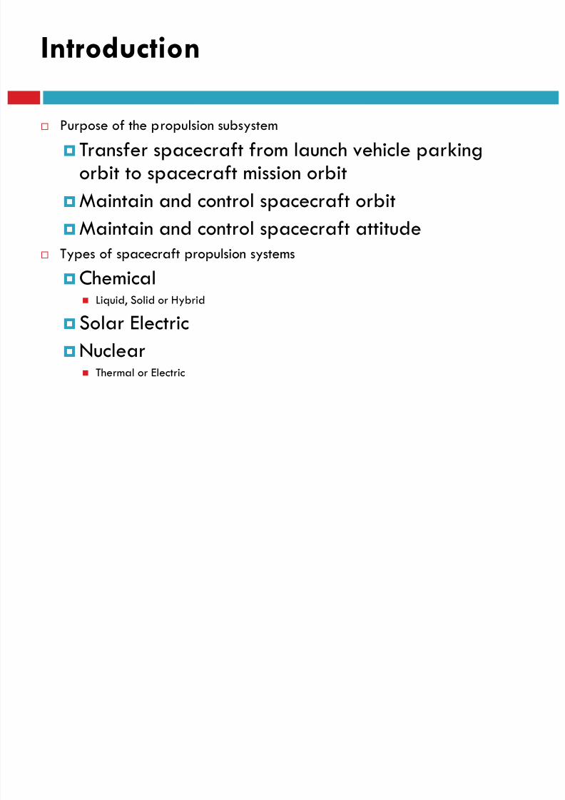
Purpose of the propulsion subsystem
Transfer spacecraft from launch vehicle parkingorbit to spacecraft mission orbit
Maintain and control spacecraft orbit
Maintain and control spacecraft attitude Types of spacecraft propulsion systems
Chemical Liquid, Solid or Hybrid
Solar Electric
Nuclear Thermal or Electric

8/23/2019 Sdac Lec 9 10 Space Propulsion
http://slidepdf.com/reader/full/sdac-lec-9-10-space-propulsion 6/239
Introduction
Spacecraft propulsion is any method used to acceleratespacecraft and artificial satellites. There are many differentmethods.
Each method has drawbacks and advantages, and spacecraftpropulsion is an active area of research.
However, most spacecraft today are propelled by forcing agas from the back/rear of the vehicle at very high speedthrough a supersonic de Laval nozzle. This sort of engine iscalled a rocket engine.
8/23/2019 Sdac Lec 9 10 Space Propulsion
http://slidepdf.com/reader/full/sdac-lec-9-10-space-propulsion 7/239
Introduction
All current spacecraft use chemical rockets (bipropellant orsolid-fuel) for launch, though some (such as the Pegasus rocketand SpaceShipOne) have used air-breathing engines on their
first stage. Most satellites have simple reliable chemical thrusters (often
monopropellant rockets) or resistojet rockets for orbital station-keeping and some use momentum wheels for attitude control.
Soviet bloc satellites have used electric propulsion for decades,
and newer Western geo-orbiting spacecraft are starting to usethem for north-south stationkeeping and orbit raising.
Interplanetary vehicles mostly use chemical rockets as well,although a few have used ion thrusters and Hall effect thrusters
(two different types of electric propulsion) to great success.

8/23/2019 Sdac Lec 9 10 Space Propulsion
http://slidepdf.com/reader/full/sdac-lec-9-10-space-propulsion 8/239
Space Propulsion Applications
Launch Vehicles
Ballistic Missiles
Earth Orbiting Satellites
Upper Stages
Interplanetary Spacecraft
Manned Spaceflight
www.army-technology.com
en.wikipedia.org
www.britannica.
com blog.wired.com
www.psrd.hawaii.edu
8/23/2019 Sdac Lec 9 10 Space Propulsion
http://slidepdf.com/reader/full/sdac-lec-9-10-space-propulsion 9/239
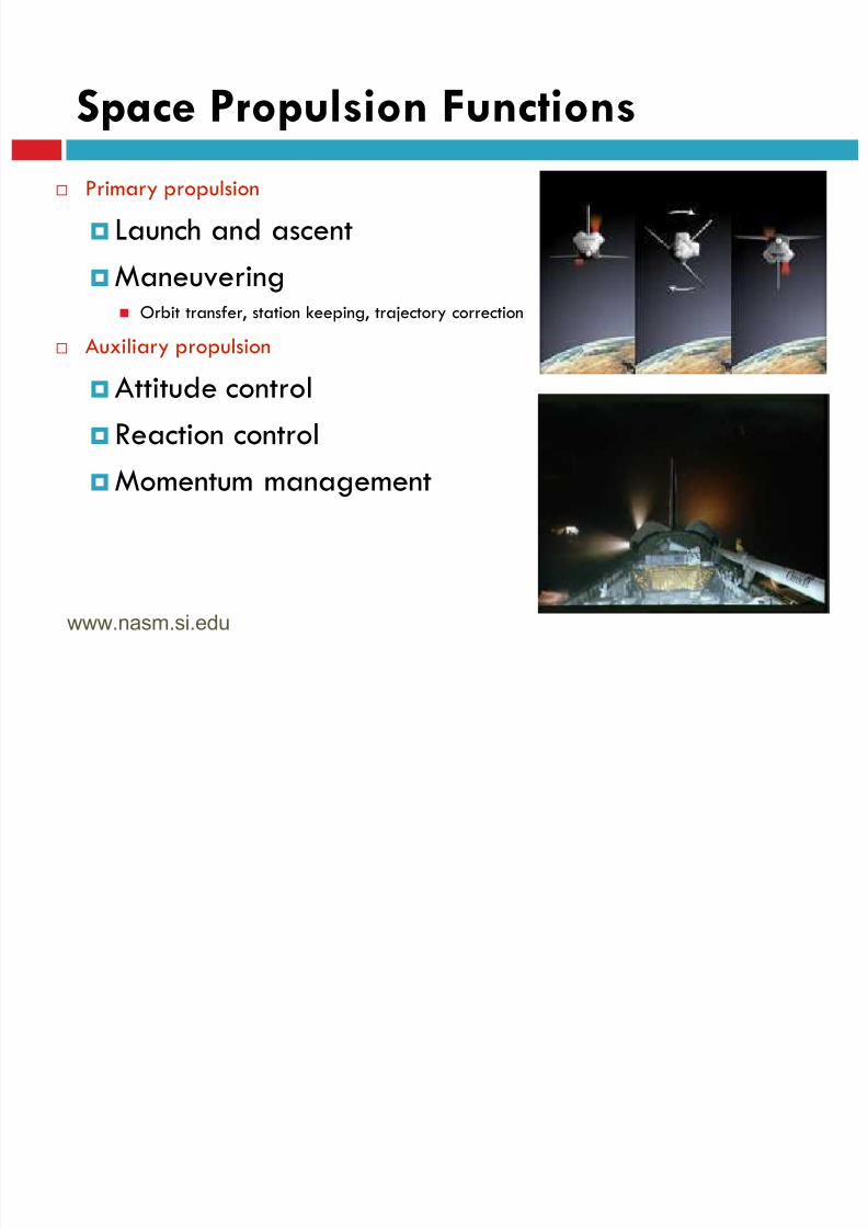
Space Propulsion Functions
Primary propulsion
Launch and ascent
Maneuvering Orbit transfer, station keeping, trajectory correction
Auxiliary propulsion
Attitude control
Reaction controlMomentum management
www.nasm.si.edu
8/23/2019 Sdac Lec 9 10 Space Propulsion
http://slidepdf.com/reader/full/sdac-lec-9-10-space-propulsion 10/239
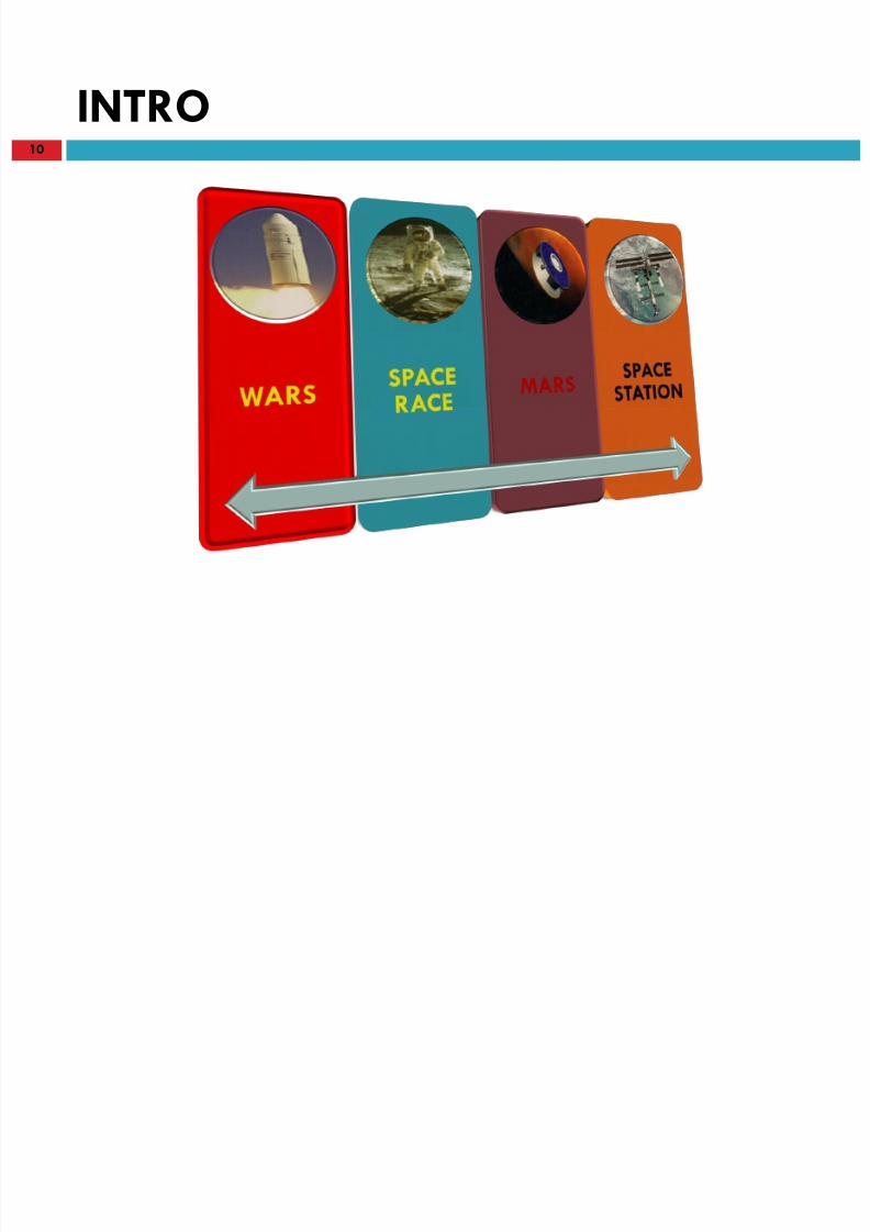
INTRO10

8/23/2019 Sdac Lec 9 10 Space Propulsion
http://slidepdf.com/reader/full/sdac-lec-9-10-space-propulsion 11/239
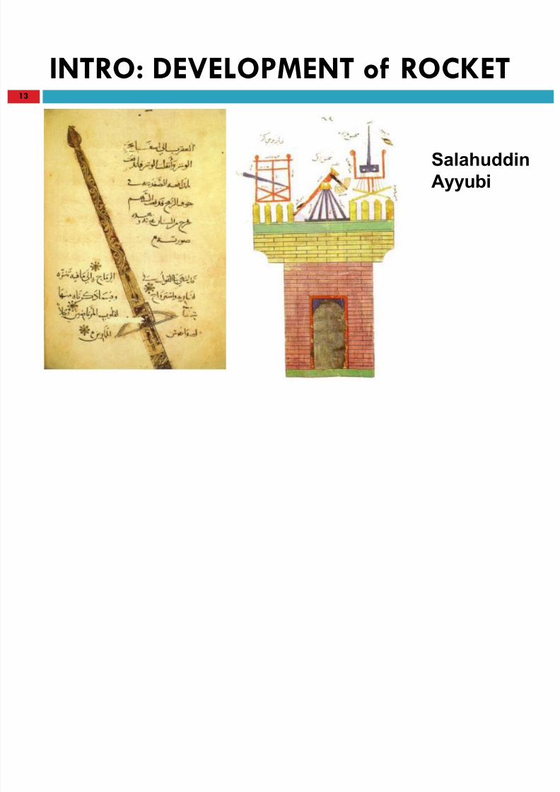
INTRO: DEVELOPMENT of ROCKET11
The real inventor of the rocket were Chinese [ Feng Jishen, (970 AD)
]
The invention of ROCKET was the practical result of experiments.
GUN POWDER & BAMBOO TUBES

8/23/2019 Sdac Lec 9 10 Space Propulsion
http://slidepdf.com/reader/full/sdac-lec-9-10-space-propulsion 12/239
8/23/2019 Sdac Lec 9 10 Space Propulsion
http://slidepdf.com/reader/full/sdac-lec-9-10-space-propulsion 13/239
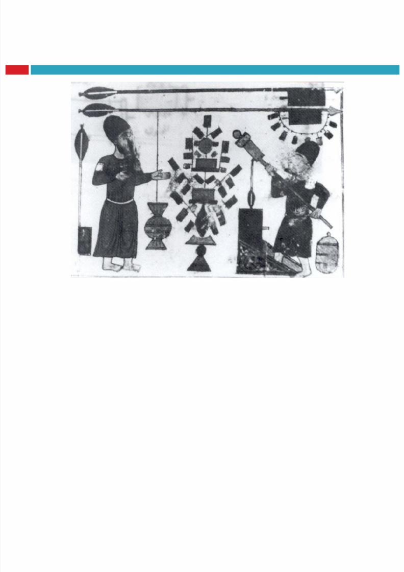
INTRO: DEVELOPMENT of ROCKET13
Salahuddin
Ayyubi
8/23/2019 Sdac Lec 9 10 Space Propulsion
http://slidepdf.com/reader/full/sdac-lec-9-10-space-propulsion 14/239

8/23/2019 Sdac Lec 9 10 Space Propulsion
http://slidepdf.com/reader/full/sdac-lec-9-10-space-propulsion 15/239
8/23/2019 Sdac Lec 9 10 Space Propulsion
http://slidepdf.com/reader/full/sdac-lec-9-10-space-propulsion 16/239

8/23/2019 Sdac Lec 9 10 Space Propulsion
http://slidepdf.com/reader/full/sdac-lec-9-10-space-propulsion 17/239
8/23/2019 Sdac Lec 9 10 Space Propulsion
http://slidepdf.com/reader/full/sdac-lec-9-10-space-propulsion 18/239
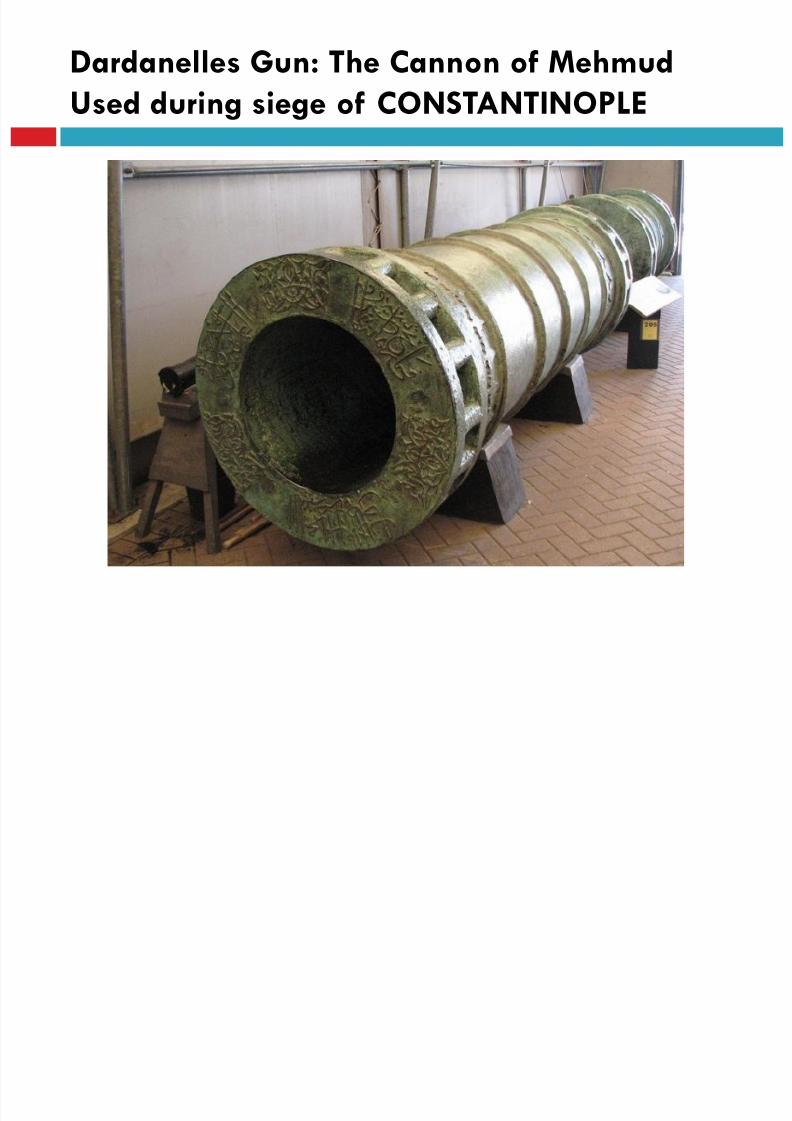
Dardanelles Gun: The Cannon of Mehmud
Used during siege of CONSTANTINOPLE
8/23/2019 Sdac Lec 9 10 Space Propulsion
http://slidepdf.com/reader/full/sdac-lec-9-10-space-propulsion 19/239
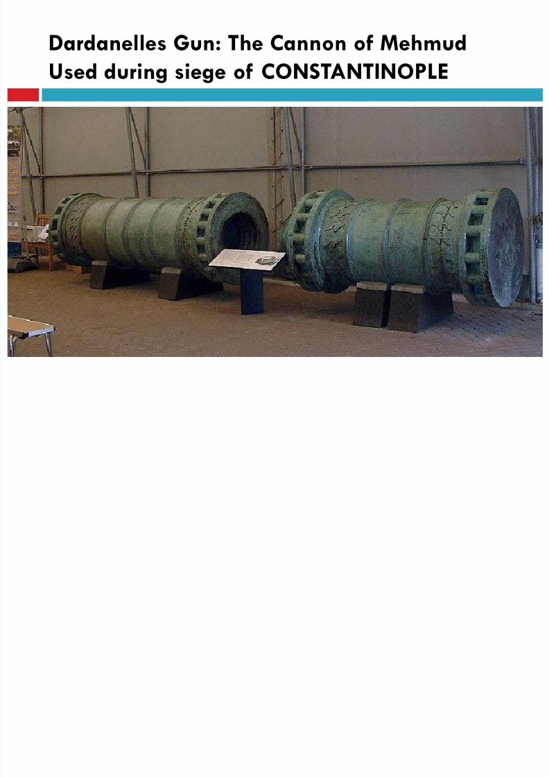
Dardanelles Gun: The Cannon of Mehmud
Used during siege of CONSTANTINOPLE

8/23/2019 Sdac Lec 9 10 Space Propulsion
http://slidepdf.com/reader/full/sdac-lec-9-10-space-propulsion 20/239
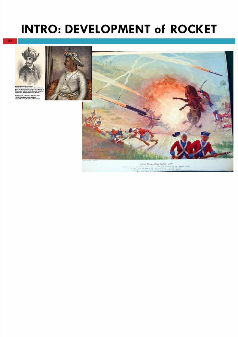
INTRO: DEVELOPMENT of ROCKET20
Kublai Khan used it during his invasion of Japan in 1275
1300s; Rockets were used as bombardment weapons asfar west as Spain, brought west by the Mongol hordes,
and the Arabs
Tipoo Sultan, in the 1770s used against the
British army in India.
8/23/2019 Sdac Lec 9 10 Space Propulsion
http://slidepdf.com/reader/full/sdac-lec-9-10-space-propulsion 21/239
INTRO: DEVELOPMENT of ROCKET21
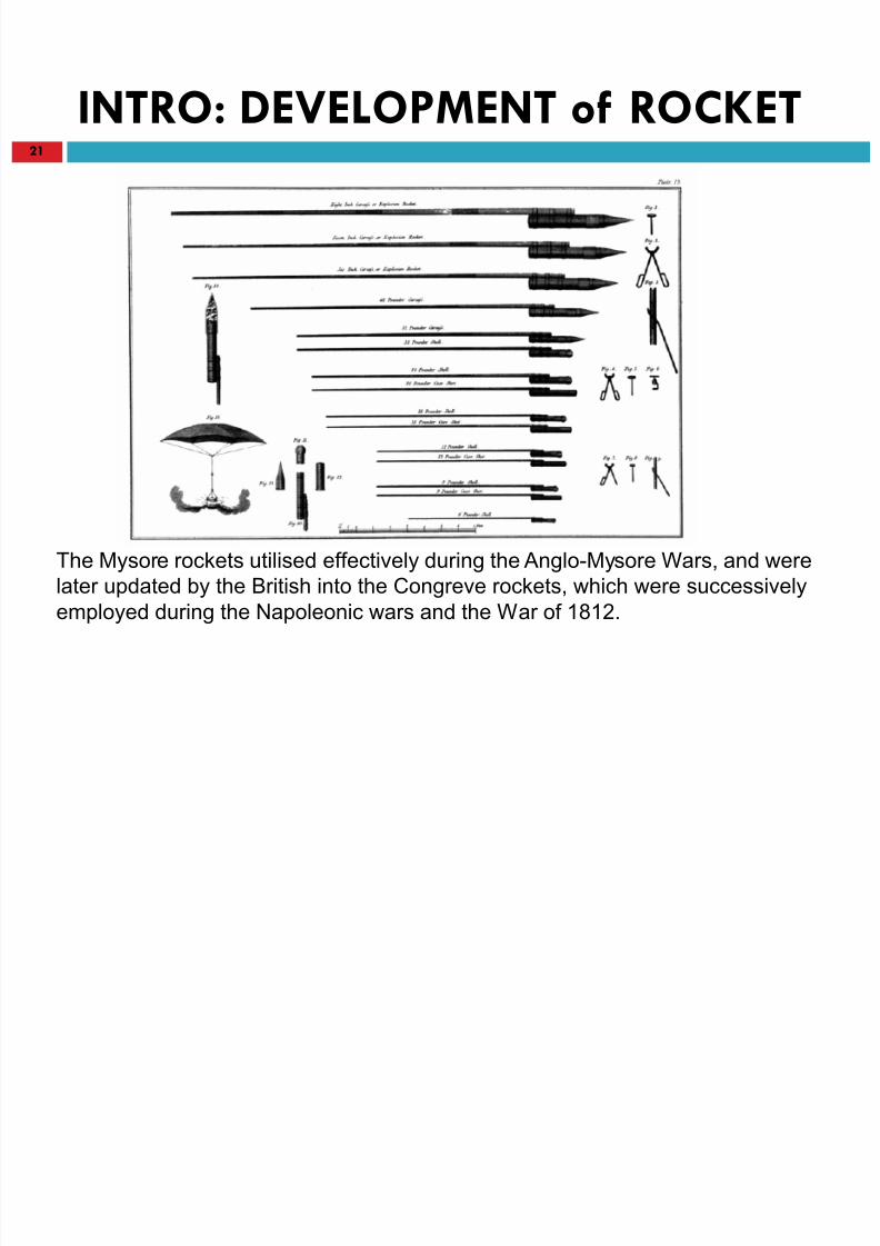
The Mysore rockets utilised effectively during the Anglo-Mysore Wars, and were
later updated by the British into the Congreve rockets, which were successively
employed during the Napoleonic wars and the War of 1812.
8/23/2019 Sdac Lec 9 10 Space Propulsion
http://slidepdf.com/reader/full/sdac-lec-9-10-space-propulsion 22/239
INTRO: DEVELOPMENT of ROCKET22
8/23/2019 Sdac Lec 9 10 Space Propulsion
http://slidepdf.com/reader/full/sdac-lec-9-10-space-propulsion 23/239
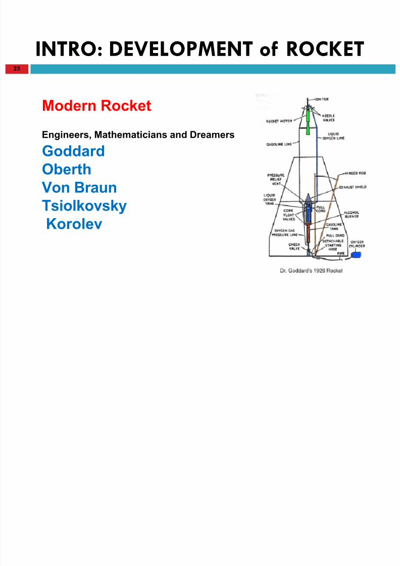
INTRO: DEVELOPMENT of ROCKET23
Goddard
Oberth
Von Braun
TsiolkovskyKorolev
Modern Rocket
Engineers, Mathematicians and Dreamers
8/23/2019 Sdac Lec 9 10 Space Propulsion
http://slidepdf.com/reader/full/sdac-lec-9-10-space-propulsion 24/239
8/23/2019 Sdac Lec 9 10 Space Propulsion
http://slidepdf.com/reader/full/sdac-lec-9-10-space-propulsion 25/239
8/23/2019 Sdac Lec 9 10 Space Propulsion
http://slidepdf.com/reader/full/sdac-lec-9-10-space-propulsion 26/239
INTRO: DEVELOPMENT of ROCKET26
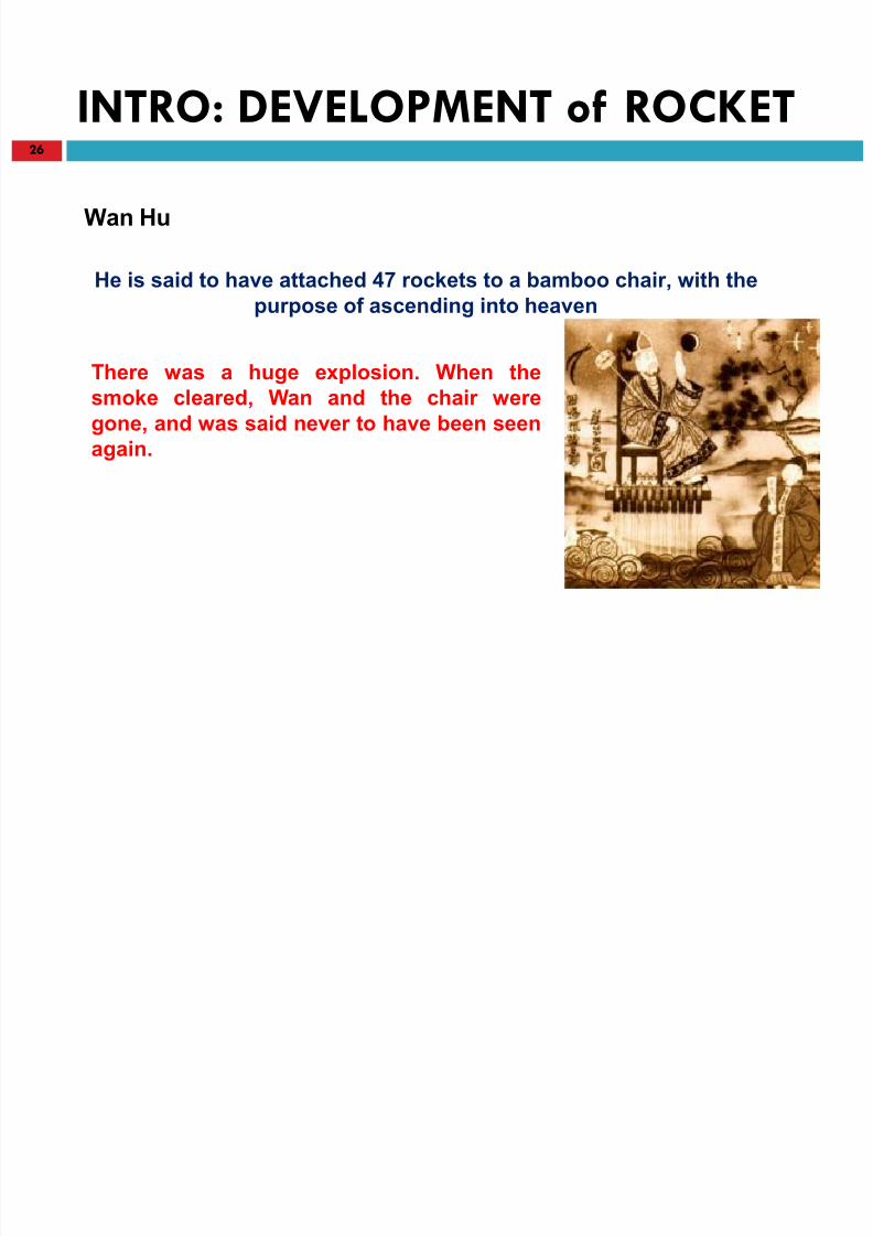
Wan Hu
He is said to have attached 47 rockets to a bamboo chair, with the
purpose of ascending into heaven
There was a huge explosion. When the
smoke cleared, Wan and the chair were
gone, and was said never to have been seen
again.
8/23/2019 Sdac Lec 9 10 Space Propulsion
http://slidepdf.com/reader/full/sdac-lec-9-10-space-propulsion 27/239
INTRO: DEVELOPMENT of ROCKET27
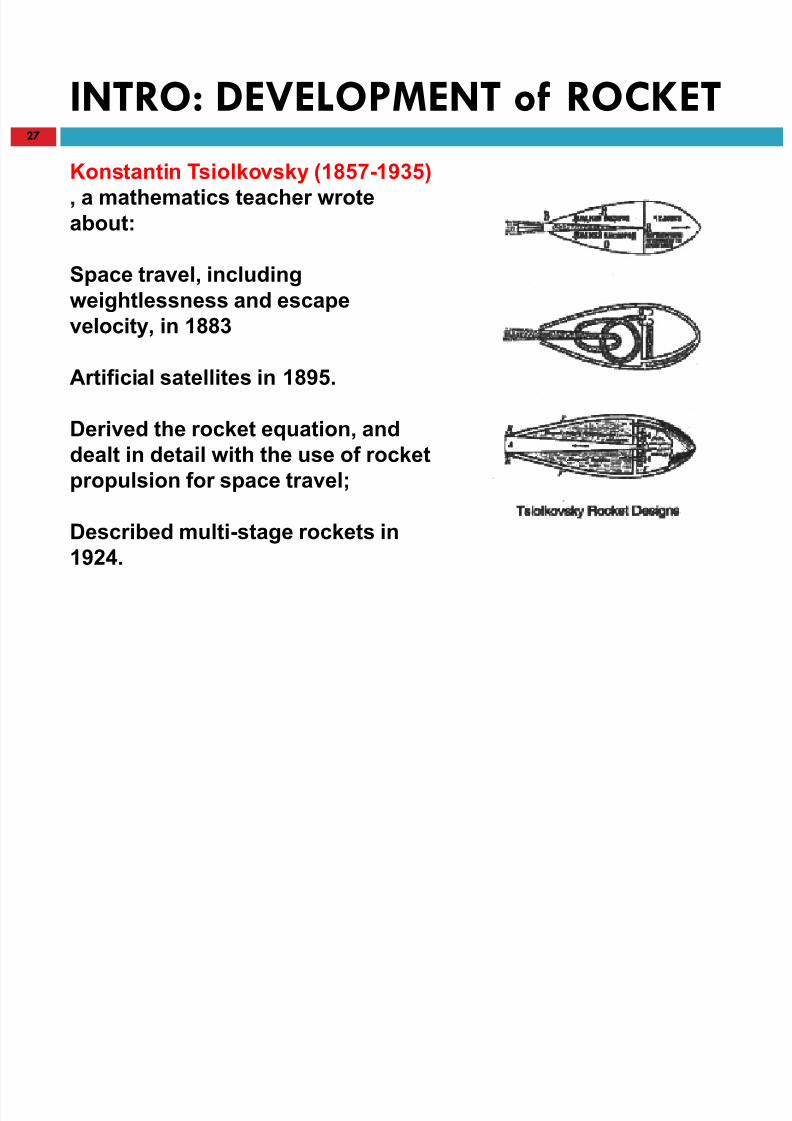
Konstantin Tsiolkovsky (1857-1935)
, a mathematics teacher wrote
about:
Space travel, includingweightlessness and escape
velocity, in 1883
Artificial satellites in 1895.
Derived the rocket equation, and
dealt in detail with the use of rocket
propulsion for space travel;
Described multi-stage rockets in
1924.
8/23/2019 Sdac Lec 9 10 Space Propulsion
http://slidepdf.com/reader/full/sdac-lec-9-10-space-propulsion 28/239
INTRO: DEVELOPMENT of ROCKET28
Hennan Oberth (1894-1992)
He published his (rejected) doctoral thesis in 1923,
as a book
Examined the use of rockets for space travel
The design of liquid-fuelled engines using alcohol
and liquid oxygen
8/23/2019 Sdac Lec 9 10 Space Propulsion
http://slidepdf.com/reader/full/sdac-lec-9-10-space-propulsion 29/239
INTRO: DEVELOPMENT of ROCKET29
Robert Goddard (1882-1945) , a professor
Published , A Method of Reaching Extreme Altitudes
Goddard's inventions included the use of gyroscopes for guidance, the use
of vanes in the jet stream to steer the rocket.
First liquid-fuelled rocket from Auburn, Massachusetts, on 16 March 1926.
Goddard mentioned the possibility of sending an unmanned rocket to the
Moon, and for this he was ridiculed by the Press
Because of his rocket experiments he was later thrown out of
Massachusetts by the fire officer
In 1960 the US government bought his patents for two million dollars

8/23/2019 Sdac Lec 9 10 Space Propulsion
http://slidepdf.com/reader/full/sdac-lec-9-10-space-propulsion 30/239
INTRO: DEVELOPMENT of ROCKET30
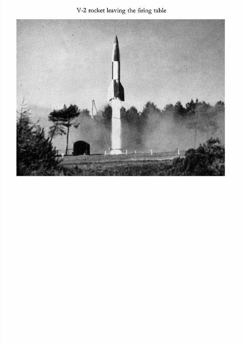
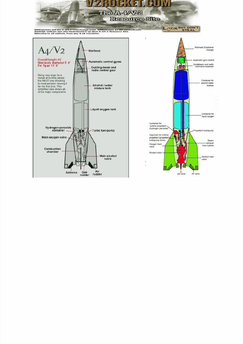
Von Braun
Enthusiastic engineers , development of the A4 liquid-fuelled
rocket which became the notorious V2 weapon.
From its launch site in Gennany, carried a 1,000- pound bomb
into the centre of London.
US took von Braun and key members of his team.

8/23/2019 Sdac Lec 9 10 Space Propulsion
http://slidepdf.com/reader/full/sdac-lec-9-10-space-propulsion 31/239
INTRO: SPACE PROGRAM31
The Russian space program has
been the most active and focused in
history:
The first artificial satellite
The first man in space
The first spacecraft on the Moon
The first docking of two spacecraft
The first space station
8/23/2019 Sdac Lec 9 10 Space Propulsion
http://slidepdf.com/reader/full/sdac-lec-9-10-space-propulsion 32/239
INTRO: SPACE PROGRAM32
The American space program :
Artificial satellite
Man in space
Man on the Moon
Docking of two spacecraft
International space station
Space Shuttle (24 ton to low Earth orbit)
Reuseablity

8/23/2019 Sdac Lec 9 10 Space Propulsion
http://slidepdf.com/reader/full/sdac-lec-9-10-space-propulsion 33/239
INTRO: SPACE PROGRAM33
The Chinese space program :
NOT a RACE
Chang Zheng, or Long March.
China's first satellite in 1970
China (third in the world) to have launched a man into space
8/23/2019 Sdac Lec 9 10 Space Propulsion
http://slidepdf.com/reader/full/sdac-lec-9-10-space-propulsion 34/239
INTRO34
Other programs
Japan, India, and Pakistan
all have space programs
8/23/2019 Sdac Lec 9 10 Space Propulsion
http://slidepdf.com/reader/full/sdac-lec-9-10-space-propulsion 35/239
REVISION
LECTURE # 9

8/23/2019 Sdac Lec 9 10 Space Propulsion
http://slidepdf.com/reader/full/sdac-lec-9-10-space-propulsion 36/239
SPECIFIC IMPULSE
LECTURE # 9

8/23/2019 Sdac Lec 9 10 Space Propulsion
http://slidepdf.com/reader/full/sdac-lec-9-10-space-propulsion 37/239

8/23/2019 Sdac Lec 9 10 Space Propulsion
http://slidepdf.com/reader/full/sdac-lec-9-10-space-propulsion 38/239
SPECIFIC IMPULSE
The specific impulse of a rocket-propellant combination is analogous to "miles per
gallon" for an automobile. All other things being equal, the V we can obtain from a
rocket stage is directly proportional to its Specific Impulse.
Consequently, the specific-impulse provides us with a convenient measure of a
rocket's intrinsic efficiency.
Once we have chosen the fuel and the oxidizer to be used, a chemical rocket's
specific impulse is largely determined by the energy contained in its propellants.
The specific impulse of a rocket-propellant combination can be defined us the number
of seconds a pound of the Propellant will produce a pound of thrust, Generally
speaking, rocket scientists strive for the Highest Specific impulse they can achieve.
The specific impulse of A Rocket can be computed by dividing the Thrust it generates
by dot , the rate at which it consumes its propellants:
w
f I sp

8/23/2019 Sdac Lec 9 10 Space Propulsion
http://slidepdf.com/reader/full/sdac-lec-9-10-space-propulsion 39/239
SPECIFIC IMPULSE
This eqn is featured in Fig below together with another useful eqn for Specific
Impulse
w
f I sp
o
e sp
g
V I
f

8/23/2019 Sdac Lec 9 10 Space Propulsion
http://slidepdf.com/reader/full/sdac-lec-9-10-space-propulsion 40/239
SPECIFIC IMPULSE
The specific impulse of a rocket-propellant combination can be defined as the number of seconds a pound of
propellant can produce a pound of thrust.
In this conceptual diagram, a rocket-powered skateboard is attached with a string to a barber pole that is, inturn. connected to a spring scale.
To measure the specific impulse of the rocket-propellant combination, ignite the rocket and adjust its valves until
it is generating one pound of thrust, as indicated by the spring scale, and then count off the number of secondsduring which its one-pound-propellant load can continuously produce one pound of thrust.
w
f I sp
o
e
sp g
V I
f
8/23/2019 Sdac Lec 9 10 Space Propulsion
http://slidepdf.com/reader/full/sdac-lec-9-10-space-propulsion 41/239
SPECIFIC IMPULSE
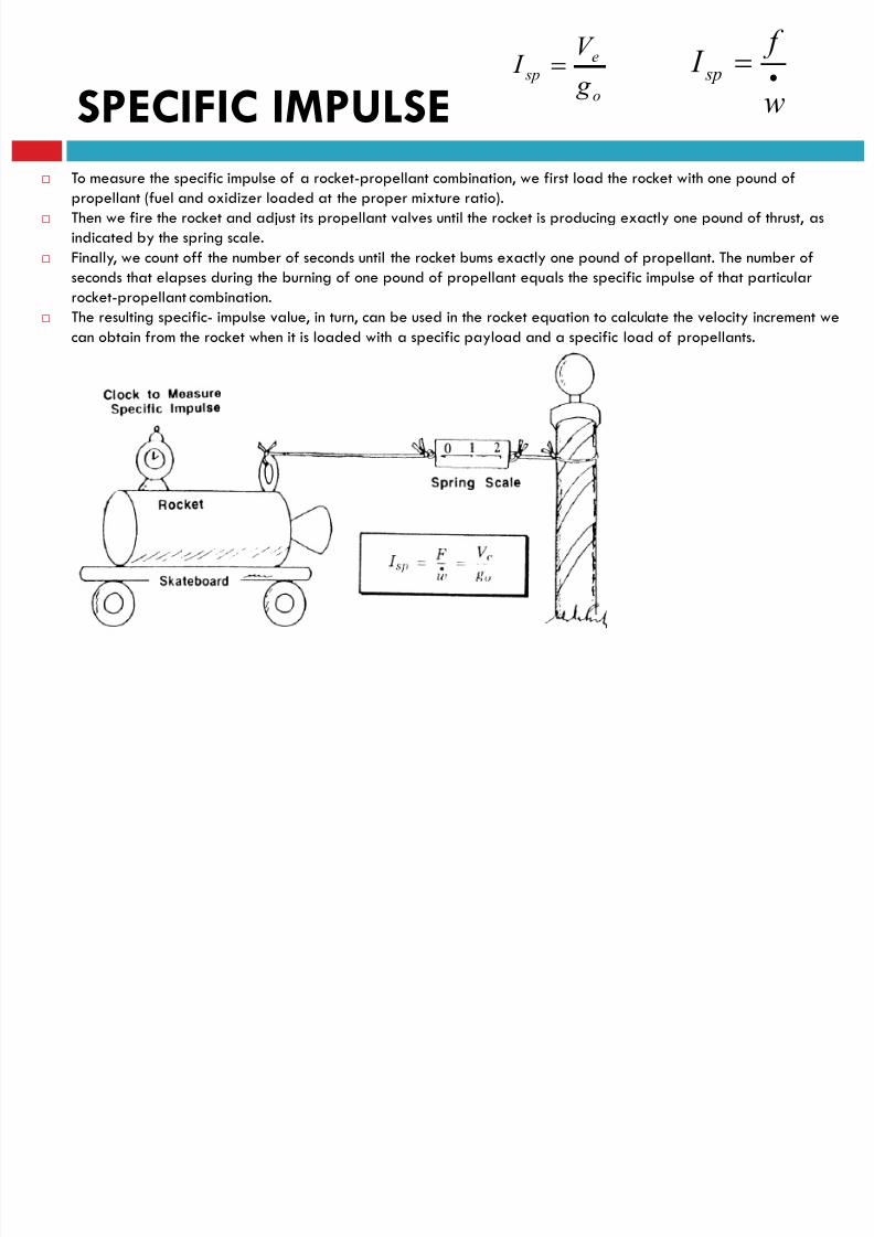
To measure the specific impulse of a rocket-propellant combination, we first load the rocket with one pound of
propellant (fuel and oxidizer loaded at the proper mixture ratio).
Then we fire the rocket and adjust its propellant valves until the rocket is producing exactly one pound of thrust, as
indicated by the spring scale.
Finally, we count off the number of seconds until the rocket bums exactly one pound of propellant. The number of
seconds that elapses during the burning of one pound of propellant equals the specific impulse of that particular
rocket-propellant combination.
The resulting specific- impulse value, in turn, can be used in the rocket equation to calculate the velocity increment we
can obtain from the rocket when it is loaded with a specific payload and a specific load of propellants.
w
f I sp
o
e
sp g
V I
f

8/23/2019 Sdac Lec 9 10 Space Propulsion
http://slidepdf.com/reader/full/sdac-lec-9-10-space-propulsion 42/239
SPECIFIC IMPULSE
When expressed in units of seconds, the specific impulse can be interpreted in thefollowing ways: the impulse divided by the sea-level weight of a unit mass of propellant the time one kilogram of propellant lasts if a force equal to the weight of one kilogram
is produced, for example a hypothetical vehicle hovering over the Earth (imagine the fuel
to be supplied from outside, so that the mass on which the thrust is applied does notreduce by spending fuel) alternatively, for engines that can not produce a large thrust: approximately the time
one kilogram of propellant lasts if an acceleration of 0.01 g of a mass of one 100kilogram is produced
100 times the time an acceleration g can be produced (i.e. a thrust equal to the weighton Earth of the current mass) with a propellant mass of 1 % of the current total mass
(100 times the time it takes in this case to reduce the total mass by 1 %) the time an acceleration g can be produced with a propellant mass of 63.2 % of the
initial total mass (the time it takes in this case to reduce the total mass by a factor e, to36.8 %)
twice the net power to produce an acceleration of 1 m/s2 to a mass which at Earth has aweight of 1 N (i.e. a mass of 102 grams)
w
f I sp
o
e
sp g
V I

8/23/2019 Sdac Lec 9 10 Space Propulsion
http://slidepdf.com/reader/full/sdac-lec-9-10-space-propulsion 43/239
ROCKET EQUATION
LECTURE # 9
8/23/2019 Sdac Lec 9 10 Space Propulsion
http://slidepdf.com/reader/full/sdac-lec-9-10-space-propulsion 44/239
Tsiovosky
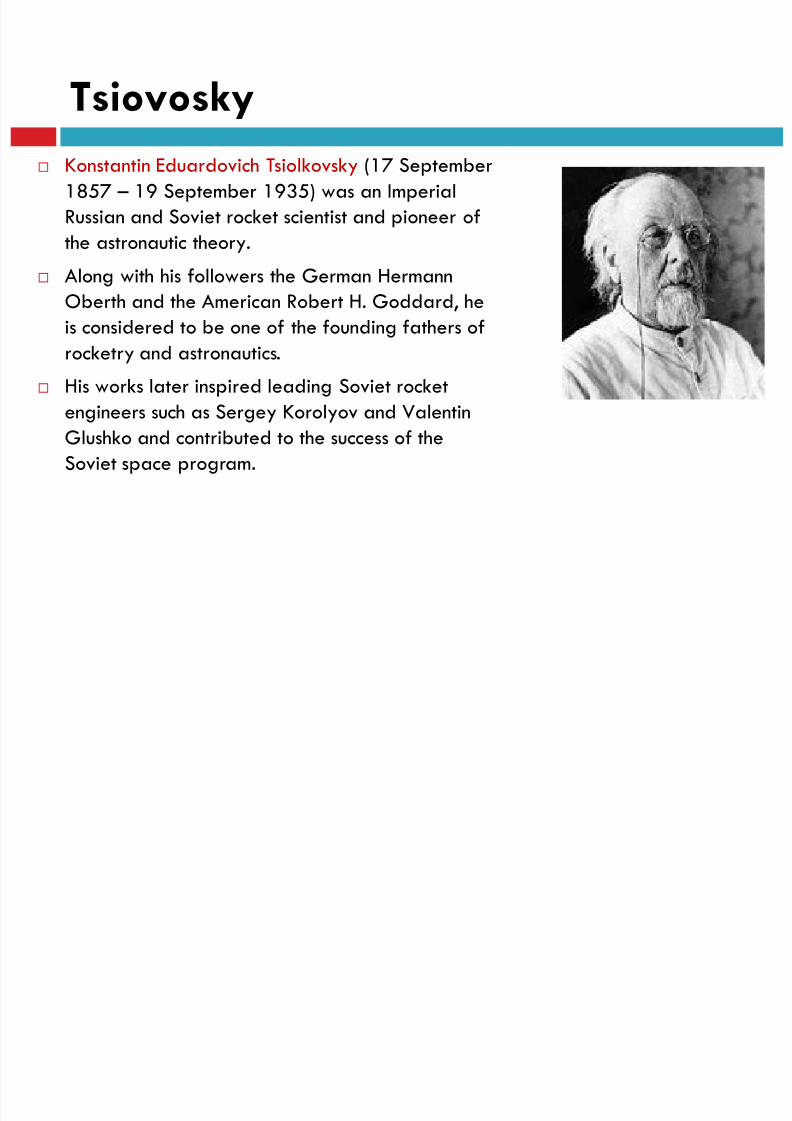
Konstantin Eduardovich Tsiolkovsky (17 September
1857 – 19 September 1935) was an ImperialRussian and Soviet rocket scientist and pioneer of
the astronautic theory.
Along with his followers the German HermannOberth and the American Robert H. Goddard, he
is considered to be one of the founding fathers of
rocketry and astronautics.
His works later inspired leading Soviet rocket
engineers such as Sergey Korolyov and ValentinGlushko and contributed to the success of the
Soviet space program.

8/23/2019 Sdac Lec 9 10 Space Propulsion
http://slidepdf.com/reader/full/sdac-lec-9-10-space-propulsion 45/239
Tsiovosky
Draft first space ship by Konstantin
Tsiolkovsky

8/23/2019 Sdac Lec 9 10 Space Propulsion
http://slidepdf.com/reader/full/sdac-lec-9-10-space-propulsion 46/239
ROCKET EQUATION
Newton’s second law, manipulated in accordance with simple relationships from
integral calculus, is used in deriving the rocket equation. That famous equation,
which is also called Tsiovosky’s equation, is highlighted at the bottom of this figure.
Tsi- ovosk/s equation indicates that the maximum velocity we can obtain from a
load of propellant is directly proportional to the specific impulse multiplied by thenatural logarithm of the ratio of the weight of the rocket at ignition and the weight
of the rocket at burnout.
The Rocket Equation
Figure includes a simple derivation of the rocket equation, which is also called
Tsiolkovsky’s equation, in honor of the Russian schoolteacher who first derived it nearly 70years ago. Notice that the derivation hinges on the proper interpretation of Newton’s
second law (F = ma), where both the mass of the rocket, w, and its acceleration, a, are
constantly changing. The end result of this step-by-step derivation is the rocket equation:
f

8/23/2019 Sdac Lec 9 10 Space Propulsion
http://slidepdf.com/reader/full/sdac-lec-9-10-space-propulsion 47/239
SPECIFIC IMPULSE
w
f I sp
o
e
sp g
V I
W
8/23/2019 Sdac Lec 9 10 Space Propulsion
http://slidepdf.com/reader/full/sdac-lec-9-10-space-propulsion 48/239
ROCKET EQUATION
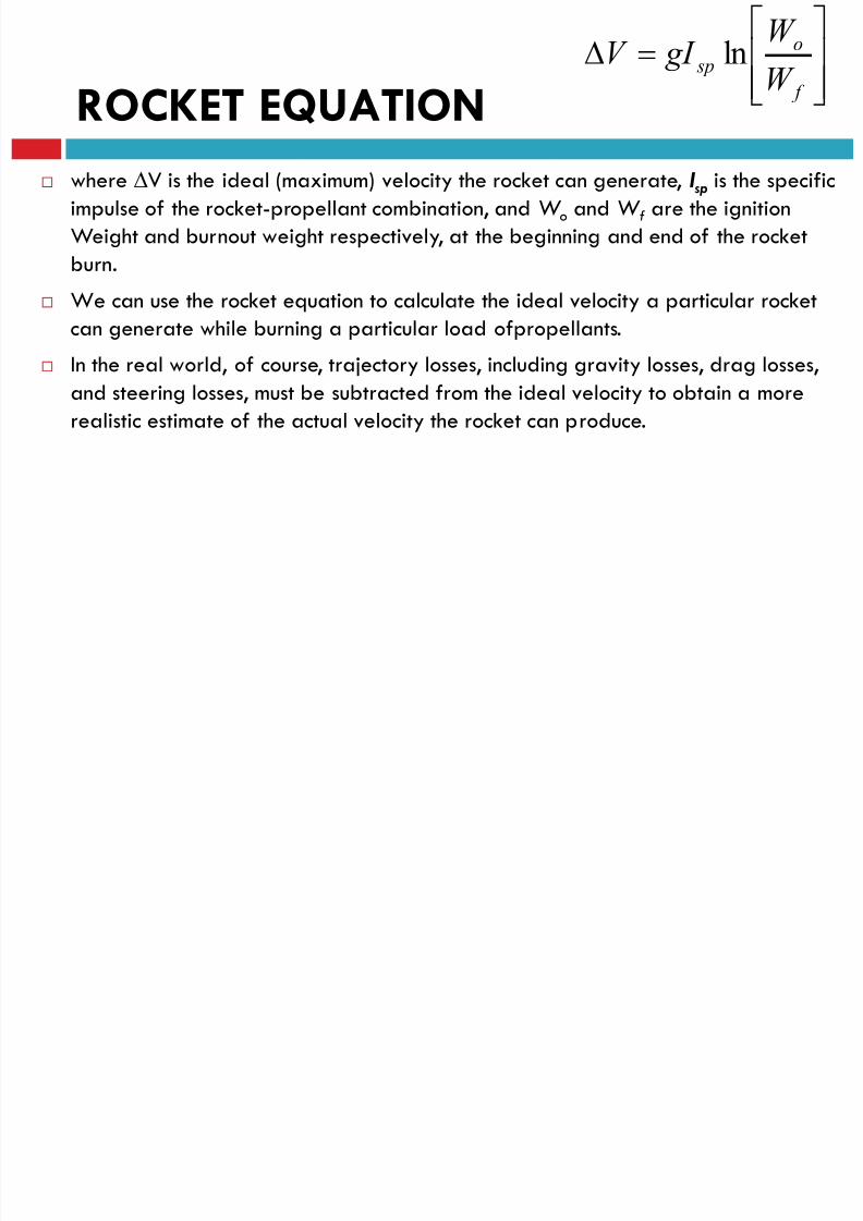
where V is the ideal (maximum) velocity the rocket can generate, I sp is the specific
impulse of the rocket-propellant combination, and W o and W f are the ignitionWeight and burnout weight respectively, at the beginning and end of the rocket
burn.
We can use the rocket equation to calculate the ideal velocity a particular rocketcan generate while burning a particular load ofpropellants.
In the real world, of course, trajectory losses, including gravity losses, drag losses,
and steering losses, must be subtracted from the ideal velocity to obtain a more
realistic estimate of the actual velocity the rocket can produce.
f
o sp
W
W gI V ln
8/23/2019 Sdac Lec 9 10 Space Propulsion
http://slidepdf.com/reader/full/sdac-lec-9-10-space-propulsion 49/239
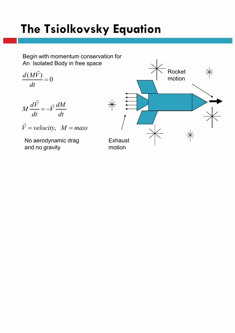
The Tsiolkovsky Equation
mass M velocityV
dt
dM V
dt
V d M
dt
V M d
,
0
)(
Begin with momentum conservation for
An Isolated Body in free space
Exhaust
motion
Rocket
motion
No aerodynamic drag
and no gravity

8/23/2019 Sdac Lec 9 10 Space Propulsion
http://slidepdf.com/reader/full/sdac-lec-9-10-space-propulsion 50/239
The Tsiolkovsky Equation Cont.
dt dM V
dt V d M
Mass of the rocket is determined by what lies within
its mechanical envelope and rocket nozzle
Mechanical
envelope
Mass leaves
envelope at Vex
leading to mass
decrease withinenvelope

8/23/2019 Sdac Lec 9 10 Space Propulsion
http://slidepdf.com/reader/full/sdac-lec-9-10-space-propulsion 51/239
)ln(
100
I
Rex
t
ex
t
ex
M M V V
rocket of timeburnt
dt dt dM
M V dt
dt V d
dt
dM V
dt
V d M
The Tsiolkovsky Equation Cont.
Mass Initial to Massmaining of Ratio M
M
Nozzletheof out Velocity Exhaust V
VelocityinChange Final V
I
R
ex
Re
8/23/2019 Sdac Lec 9 10 Space Propulsion
http://slidepdf.com/reader/full/sdac-lec-9-10-space-propulsion 52/239
)ln(
R
I ex
M
M V V
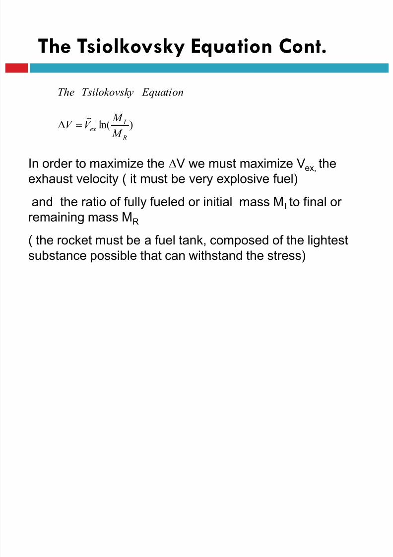
Equation yTsilokovsk The
The Tsiolkovsky Equation Cont.
In order to maximize the V we must maximize Vex, the
exhaust velocity ( it must be very explosive fuel)
and the ratio of fully fueled or initial mass MI to final or remaining mass MR
( the rocket must be a fuel tank, composed of the lightest
substance possible that can withstand the stress)
8/23/2019 Sdac Lec 9 10 Space Propulsion
http://slidepdf.com/reader/full/sdac-lec-9-10-space-propulsion 53/239
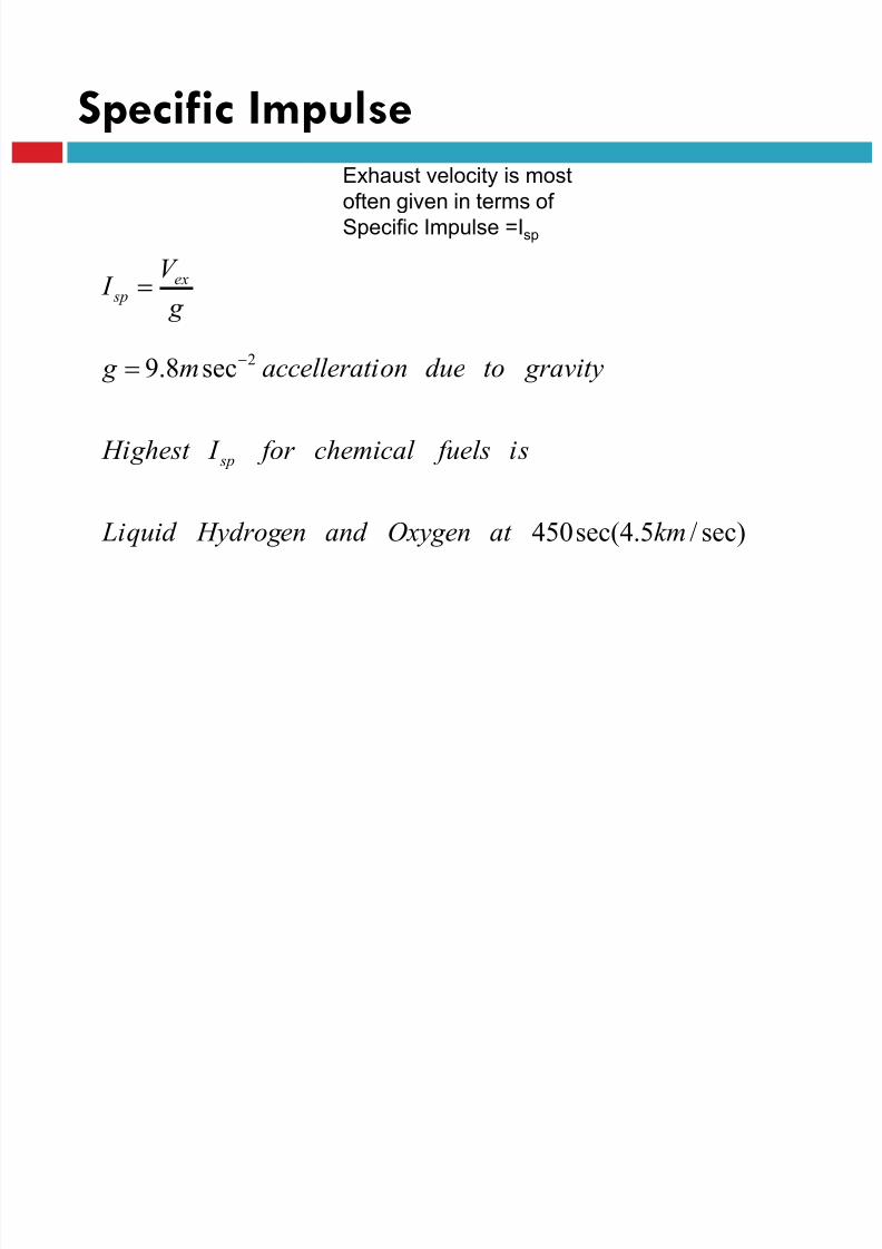
Specific Impulse
Exhaust velocity is most
often given in terms of
Specific Impulse =Isp
sec)/5.4sec(450
sec8.9 2
kmat Oxygenand Hydrogen Liquid
is fuelschemical for I Highest
gravitytodueionaccellerat m g
g
V I
sp
ex sp
8/23/2019 Sdac Lec 9 10 Space Propulsion
http://slidepdf.com/reader/full/sdac-lec-9-10-space-propulsion 54/239
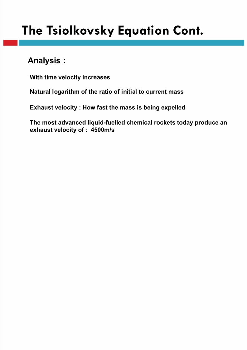
Analysis :
With time velocity increases
Natural logarithm of the ratio of initial to current mass
Exhaust velocity : How fast the mass is being expelled
The most advanced liquid-fuelled chemical rockets today produce an
exhaust velocity of : 4500m/s
The Tsiolkovsky Equation Cont.
8/23/2019 Sdac Lec 9 10 Space Propulsion
http://slidepdf.com/reader/full/sdac-lec-9-10-space-propulsion 55/239
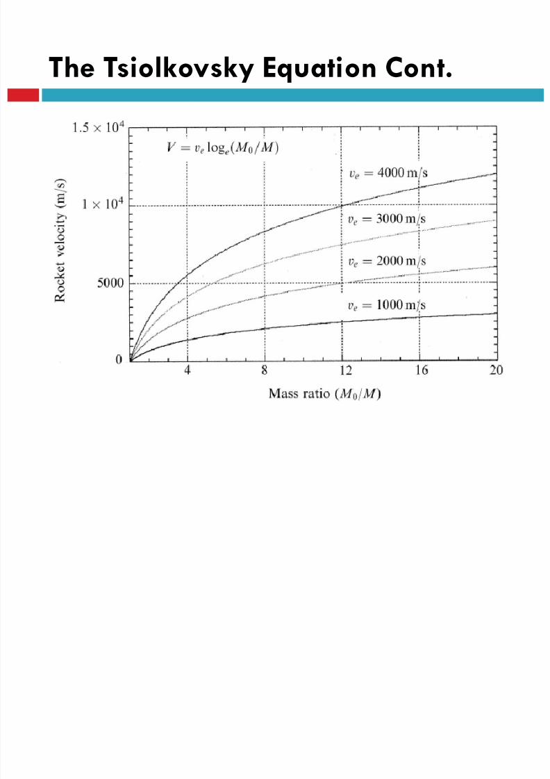
The Tsiolkovsky Equation Cont.
8/23/2019 Sdac Lec 9 10 Space Propulsion
http://slidepdf.com/reader/full/sdac-lec-9-10-space-propulsion 56/239
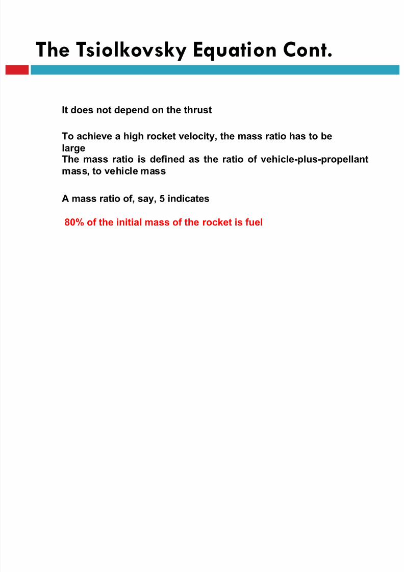
The Tsiolkovsky Equation Cont.
It does not depend on the thrust
To achieve a high rocket velocity, the mass ratio has to be
largeThe mass ratio is defined as the ratio of vehicle-plus-propellant
mass, to vehicle mass
A mass ratio of, say, 5 indicates
80% of the initial mass of the rocket is fuel

8/23/2019 Sdac Lec 9 10 Space Propulsion
http://slidepdf.com/reader/full/sdac-lec-9-10-space-propulsion 57/239
The Tsiolkovsky Equation Cont.
Car, which has a typical empty mass of 1.5 ton, and a fuel mass of 40 kg
A mass ratio of 1.003
The rocket can travel faster than the speed of its exhaust.
The point at which the rocket speed exceeds the exhaust speed is
when the mass ratio becomes equal to e, the base of natural
logarithms
Tsiolkovsky calculated how fast a rocket needs to travel to reach
space.
and determined : there was a LIMITA mass ratio of 10 is almost impossible to achieve.
8/23/2019 Sdac Lec 9 10 Space Propulsion
http://slidepdf.com/reader/full/sdac-lec-9-10-space-propulsion 58/239
R
Fu elBurned ex
R
FuelBurned ex
R
I ex
R
Fu elBurned
R
Fu elBurned
R
FuelBurned R
R
I
M
M V
M
M V
M
M V V
Becomes EquationThe
M
M where
M
M
M
M M
M
M For
)1ln()ln(
1
1
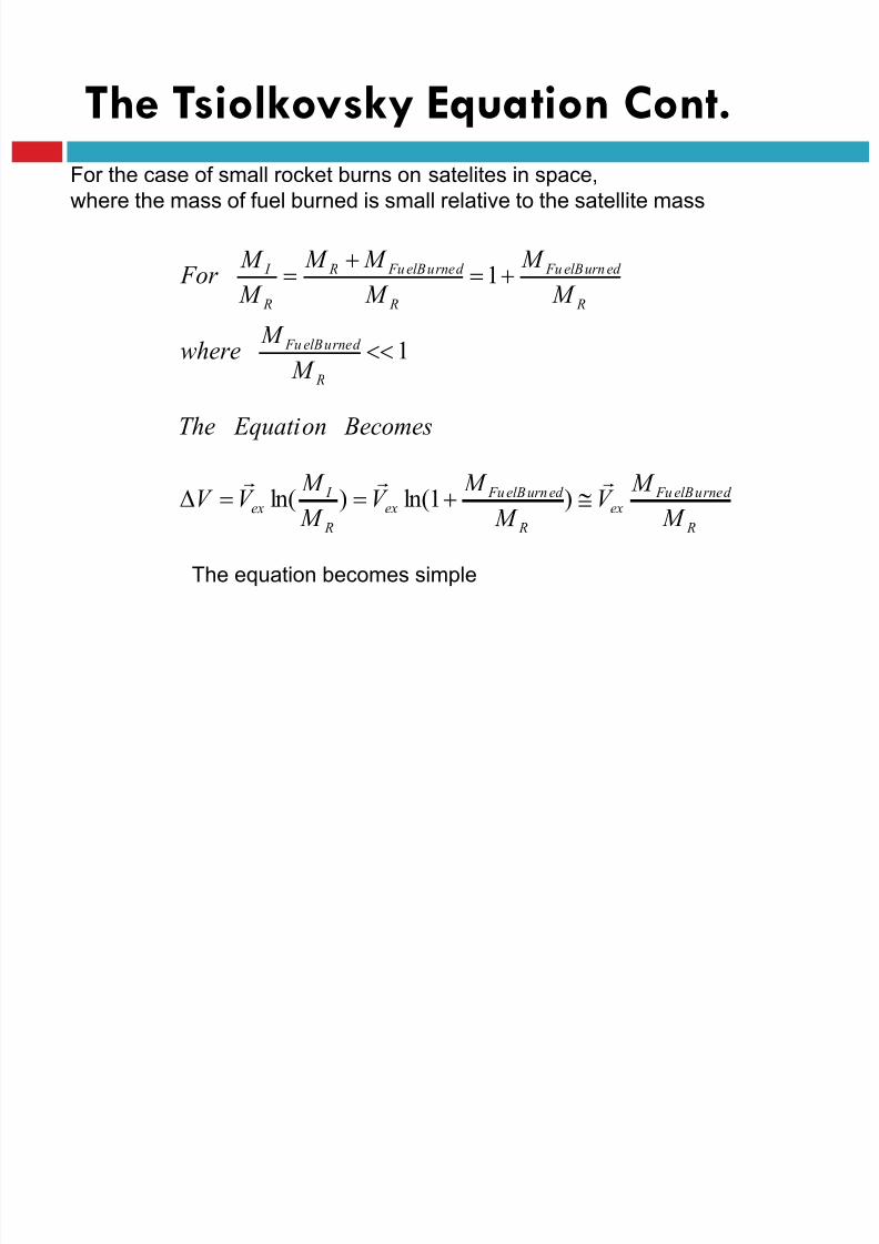
The Tsiolkovsky Equation Cont.
For the case of small rocket burns on satelites in space,
where the mass of fuel burned is small relative to the satellite mass
The equation becomes simple
fV

8/23/2019 Sdac Lec 9 10 Space Propulsion
http://slidepdf.com/reader/full/sdac-lec-9-10-space-propulsion 59/239
SPECIFIC IMPULSE
w
f I sp
o
e
sp g
V I
8/23/2019 Sdac Lec 9 10 Space Propulsion
http://slidepdf.com/reader/full/sdac-lec-9-10-space-propulsion 60/239
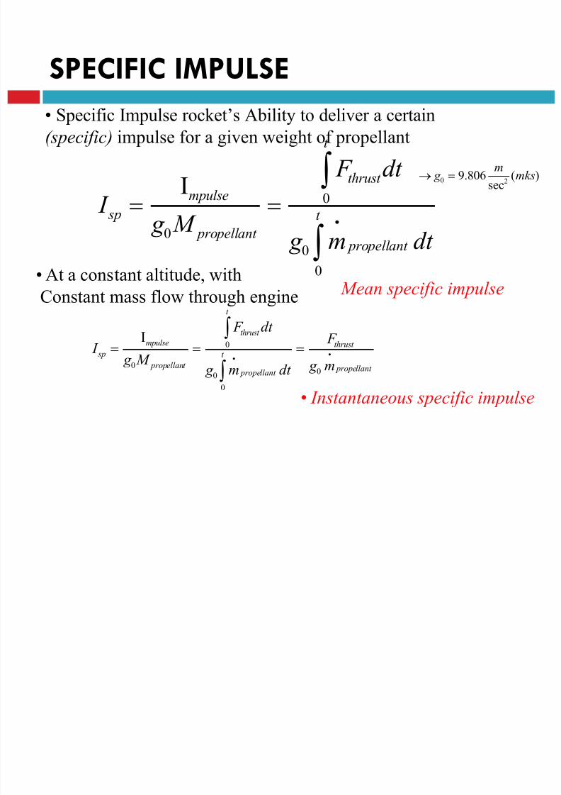
SPECIFIC IMPULSE
• Specific Impulse rocket’s Ability to deliver a certain
(specific) impulse for a given weight of propellant
I sp Impulse
g 0 M propellant
F thrust 0
t
dt
g 0 m•
propellant dt 0
t
g 0 9.806m
sec2(mks)
Mean specific impulse
• At a constant altitude, with
Constant mass flow through engine
I sp Impulse
g 0 M propellant
F thrust 0
t
dt
g 0 m•
propellant dt
0
t
F thrust
g 0 m•
propellant
• Instantaneous specific impulse

8/23/2019 Sdac Lec 9 10 Space Propulsion
http://slidepdf.com/reader/full/sdac-lec-9-10-space-propulsion 61/239
Rocket Equation
V V final V 0 M 0 M final m propellant
V g 0 I sp ln 1m propellant
M final
g 0 I sp ln 1 P mf
P mf "propellant mass fraction"
• Sometimesm propellant
M final
m propellant
Is also called
propellant mass
Fraction or “load mass fraction”
8/23/2019 Sdac Lec 9 10 Space Propulsion
http://slidepdf.com/reader/full/sdac-lec-9-10-space-propulsion 62/239
LECTURE # 9
SPACE PROPULSIONREQUIREMENT
8/23/2019 Sdac Lec 9 10 Space Propulsion
http://slidepdf.com/reader/full/sdac-lec-9-10-space-propulsion 63/239
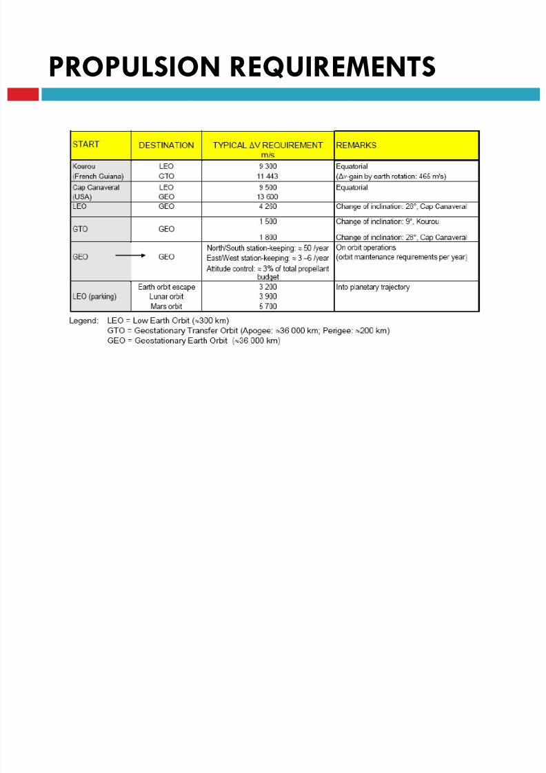
PROPULSION REQUIREMENTS
8/23/2019 Sdac Lec 9 10 Space Propulsion
http://slidepdf.com/reader/full/sdac-lec-9-10-space-propulsion 64/239
PROPULSION REQUIREMENTS
8/23/2019 Sdac Lec 9 10 Space Propulsion
http://slidepdf.com/reader/full/sdac-lec-9-10-space-propulsion 65/239
PROPULSION REQUIREMENTS
8/23/2019 Sdac Lec 9 10 Space Propulsion
http://slidepdf.com/reader/full/sdac-lec-9-10-space-propulsion 66/239
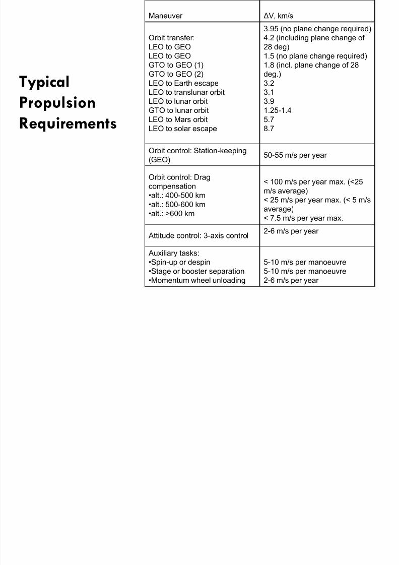
Typical
Propulsion
Requirements
Maneuver ΔV, km/s
8/23/2019 Sdac Lec 9 10 Space Propulsion
http://slidepdf.com/reader/full/sdac-lec-9-10-space-propulsion 67/239
Typical
Propulsion
Requirements
Orbit transfer:
LEO to GEO
LEO to GEO
GTO to GEO (1)
GTO to GEO (2)LEO to Earth escape
LEO to translunar orbit
LEO to lunar orbit
GTO to lunar orbit
LEO to Mars orbit
LEO to solar escape
3.95 (no plane change required)
4.2 (including plane change of
28 deg)
1.5 (no plane change required)
1.8 (incl. plane change of 28
deg.)3.2
3.1
3.9
1.25-1.4
5.7
8.7
Orbit control: Station-keeping
(GEO)50-55 m/s per year
Orbit control: Drag
compensation
•alt.: 400-500 km
•alt.: 500-600 km
•alt.: >600 km
< 100 m/s per year max. (<25
m/s average)
< 25 m/s per year max. (< 5 m/s
average)< 7.5 m/s per year max.
Attitude control: 3-axis control2-6 m/s per year
Auxiliary tasks:
•Spin-up or despin
•Stage or booster separation
•Momentum wheel unloading
5-10 m/s per manoeuvre
5-10 m/s per manoeuvre
2-6 m/s per year
8/23/2019 Sdac Lec 9 10 Space Propulsion
http://slidepdf.com/reader/full/sdac-lec-9-10-space-propulsion 68/239
LECTURE # 9
SPACECRAFT PROPULSIONEQUATIONS
8/23/2019 Sdac Lec 9 10 Space Propulsion
http://slidepdf.com/reader/full/sdac-lec-9-10-space-propulsion 69/239
Equations
Thrust
Mass Flow
Impulse
Specific Impulse
Ideal Rocket Equation
Propellant Tank Mass
8/23/2019 Sdac Lec 9 10 Space Propulsion
http://slidepdf.com/reader/full/sdac-lec-9-10-space-propulsion 70/239
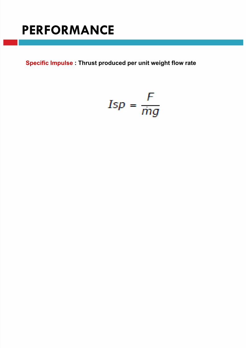
PERFORMANCE
Specific Impulse : Thrust produced per unit weight flow rate
8/23/2019 Sdac Lec 9 10 Space Propulsion
http://slidepdf.com/reader/full/sdac-lec-9-10-space-propulsion 71/239
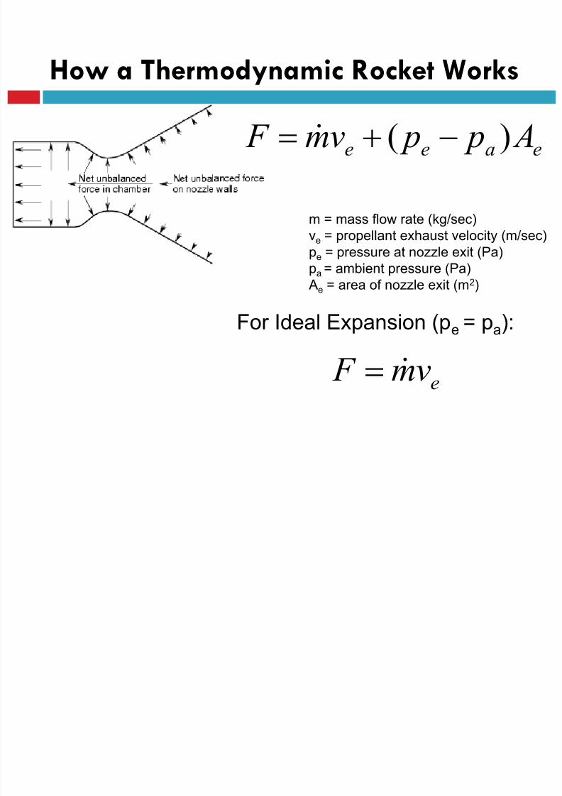
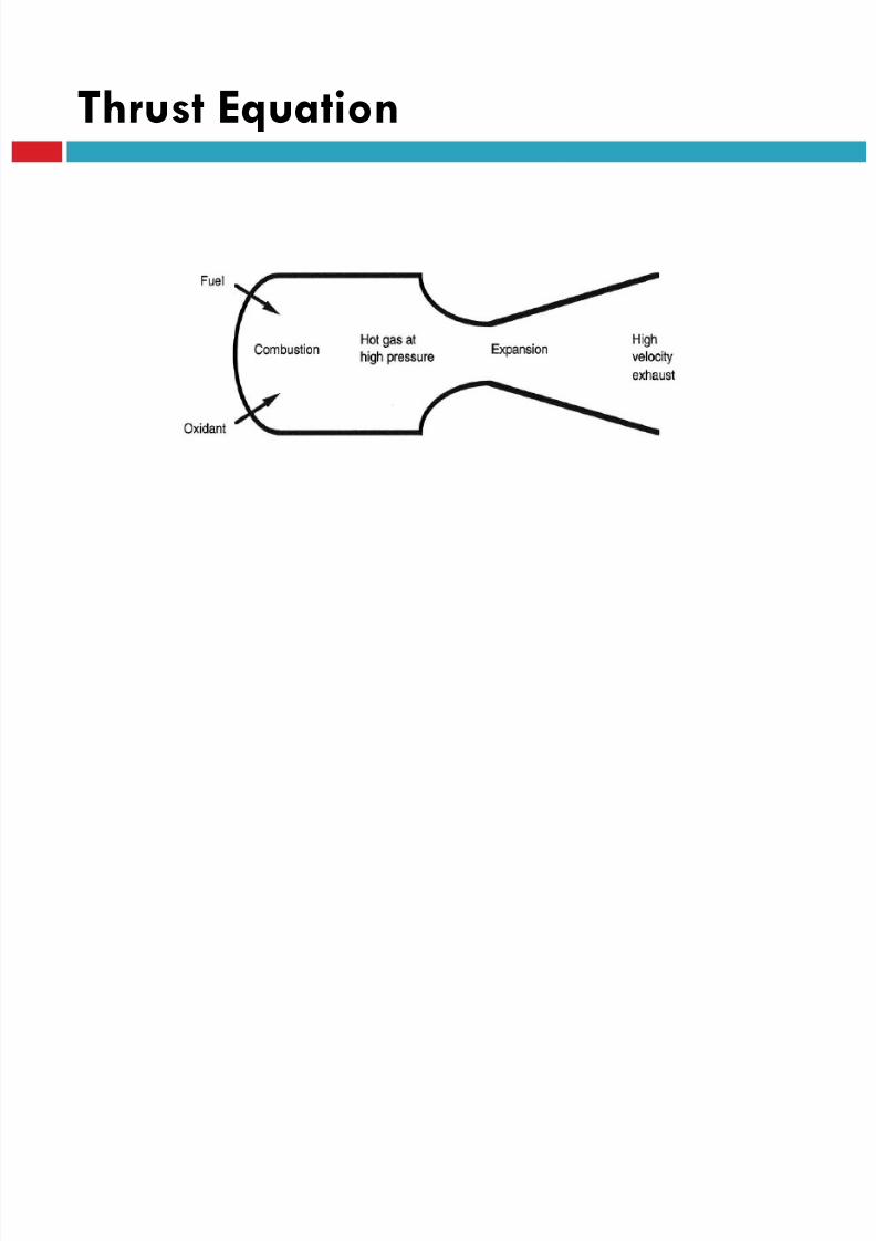
How a Thermodynamic Rocket Works
eaee A p pvm F )(
m = mass flow rate (kg/sec)
ve = propellant exhaust velocity (m/sec)
pe = pressure at nozzle exit (Pa)
pa = ambient pressure (Pa)
Ae = area of nozzle exit (m2)
e
vm F
For Ideal Expansion (pe = pa):
8/23/2019 Sdac Lec 9 10 Space Propulsion
http://slidepdf.com/reader/full/sdac-lec-9-10-space-propulsion 72/239
Thrust Equation

8/23/2019 Sdac Lec 9 10 Space Propulsion
http://slidepdf.com/reader/full/sdac-lec-9-10-space-propulsion 73/239
Thrust Equation
P2
P
T
PeTe
Ae
F1 F2
8/23/2019 Sdac Lec 9 10 Space Propulsion
http://slidepdf.com/reader/full/sdac-lec-9-10-space-propulsion 74/239
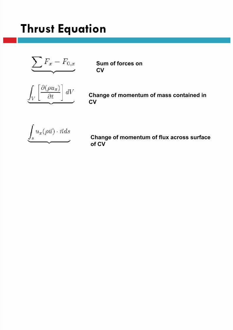
Thrust Equation
Change of momentum of flux across surface
of CV
Sum of forces on
CV
Change of momentum of mass contained in
CV
8/23/2019 Sdac Lec 9 10 Space Propulsion
http://slidepdf.com/reader/full/sdac-lec-9-10-space-propulsion 75/239
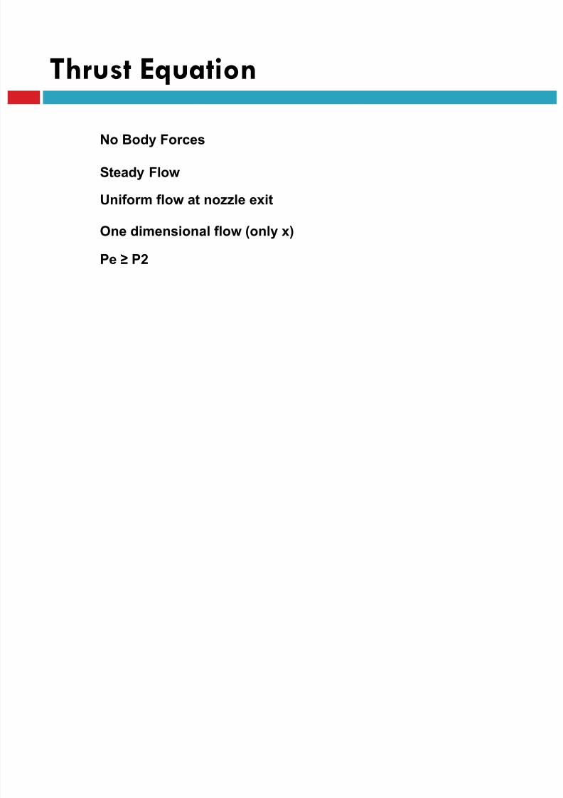
Thrust Equation
No Body Forces
Steady Flow
Uniform flow at nozzle exit
One dimensional flow (only x)
Pe ≥ P2
8/23/2019 Sdac Lec 9 10 Space Propulsion
http://slidepdf.com/reader/full/sdac-lec-9-10-space-propulsion 76/239
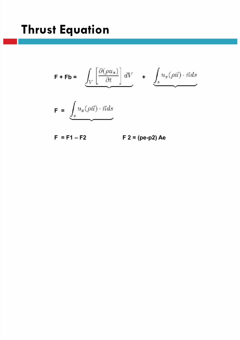
Thrust Equation
F + Fb = +
F =
F = F1 – F2 F 2 = (pe-p2) Ae
8/23/2019 Sdac Lec 9 10 Space Propulsion
http://slidepdf.com/reader/full/sdac-lec-9-10-space-propulsion 77/239
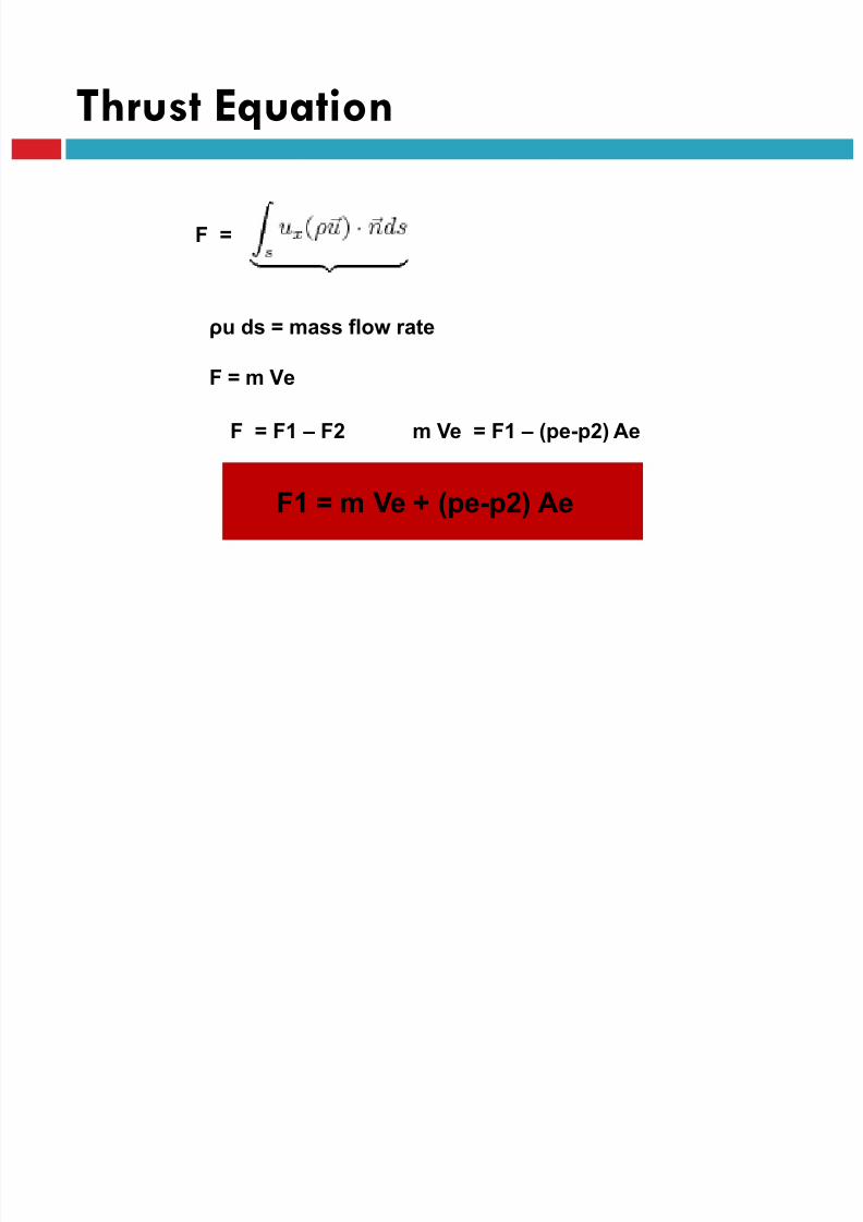
Thrust Equation
F =
ρu ds = mass flow rate
F = m Ve
F = F1 – F2 m Ve = F1 – (pe-p2) Ae
F1 = m Ve + (pe-p2) Ae
8/23/2019 Sdac Lec 9 10 Space Propulsion
http://slidepdf.com/reader/full/sdac-lec-9-10-space-propulsion 78/239
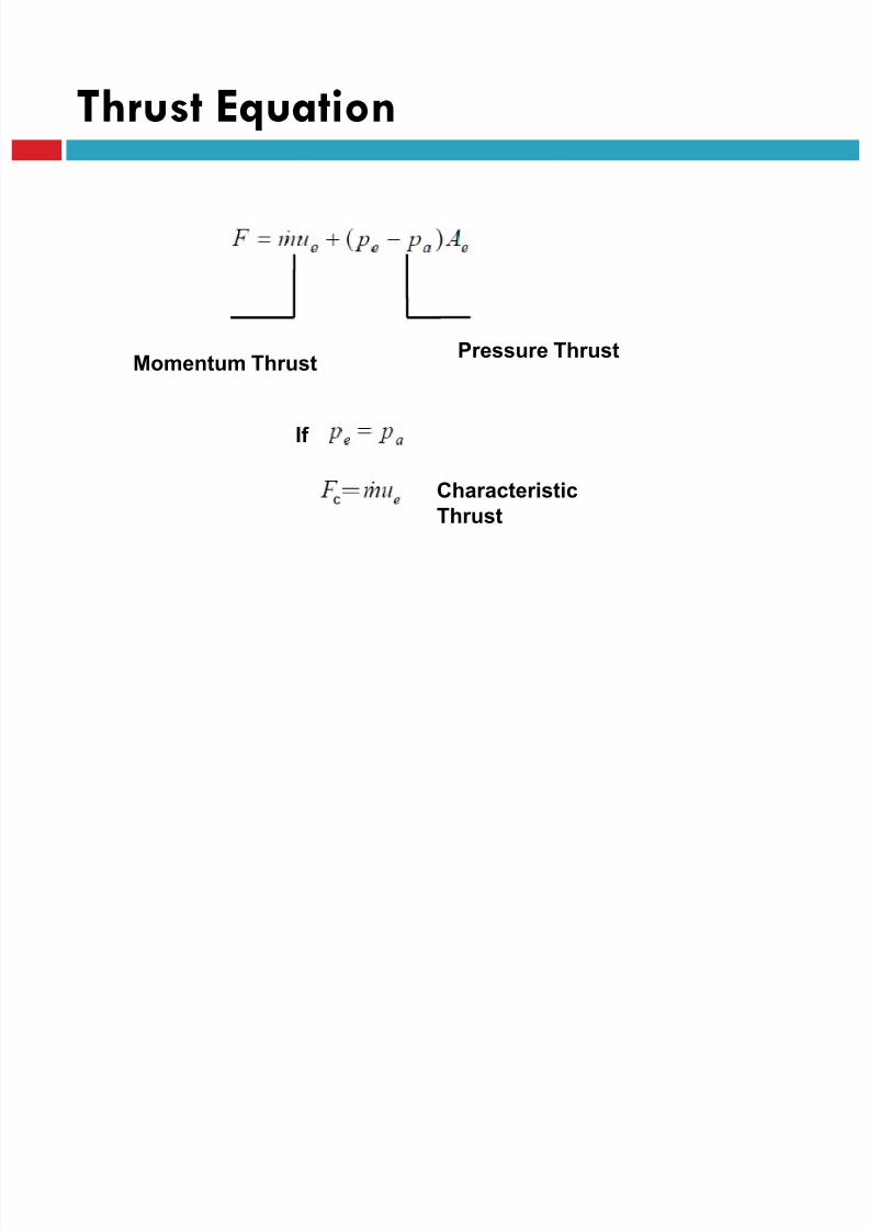
Thrust Equation
If
Pressure ThrustMomentum Thrust
Characteristic
Thrust

8/23/2019 Sdac Lec 9 10 Space Propulsion
http://slidepdf.com/reader/full/sdac-lec-9-10-space-propulsion 79/239
Thrust Equation
Effective exhaust velocity
Characteristic Velocity
8/23/2019 Sdac Lec 9 10 Space Propulsion
http://slidepdf.com/reader/full/sdac-lec-9-10-space-propulsion 80/239
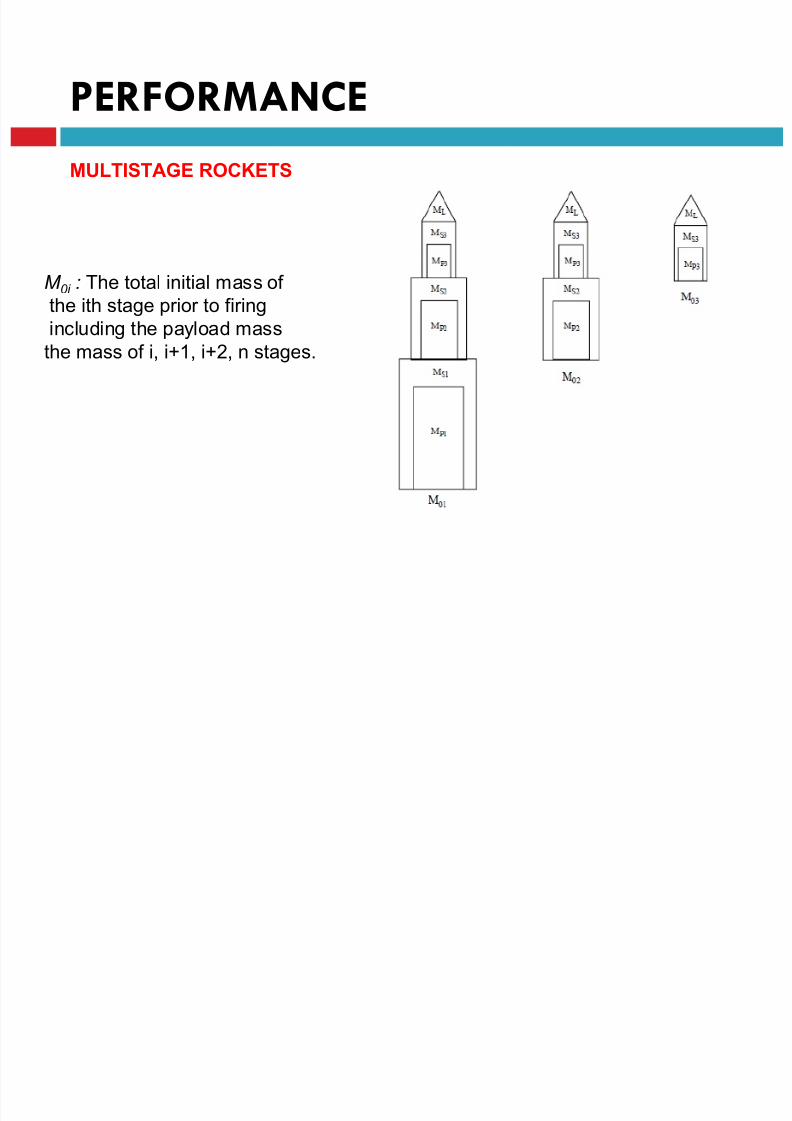
PERFORMANCE
MULTISTAGE ROCKETS
M 0i : The total initial mass of the ith stage prior to firing
including the payload mass
the mass of i, i+1, i+2, n stages.
8/23/2019 Sdac Lec 9 10 Space Propulsion
http://slidepdf.com/reader/full/sdac-lec-9-10-space-propulsion 81/239
PERFORMANCE
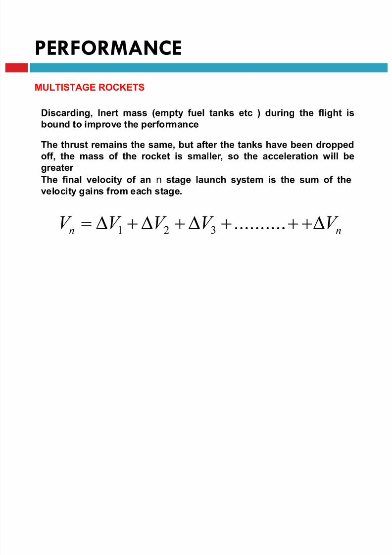
MULTISTAGE ROCKETS
Discarding, Inert mass (empty fuel tanks etc ) during the flight is
bound to improve the performance
The thrust remains the same, but after the tanks have been dropped
off, the mass of the rocket is smaller, so the acceleration will be
greater
The final velocity of an n stage launch system is the sum of the
velocity gains from each stage.
nn V V V V V ...........321

8/23/2019 Sdac Lec 9 10 Space Propulsion
http://slidepdf.com/reader/full/sdac-lec-9-10-space-propulsion 82/239
PERFORMANCE
The mass ratio of the single rocket
F S
P F S
o
M M
M M M R
The rocket is then divided into two rockets, each having half the fuel
and stacked one on top of the other
The first rocket is ignited, and burns until all its fuel is exhausted
8/23/2019 Sdac Lec 9 10 Space Propulsion
http://slidepdf.com/reader/full/sdac-lec-9-10-space-propulsion 83/239
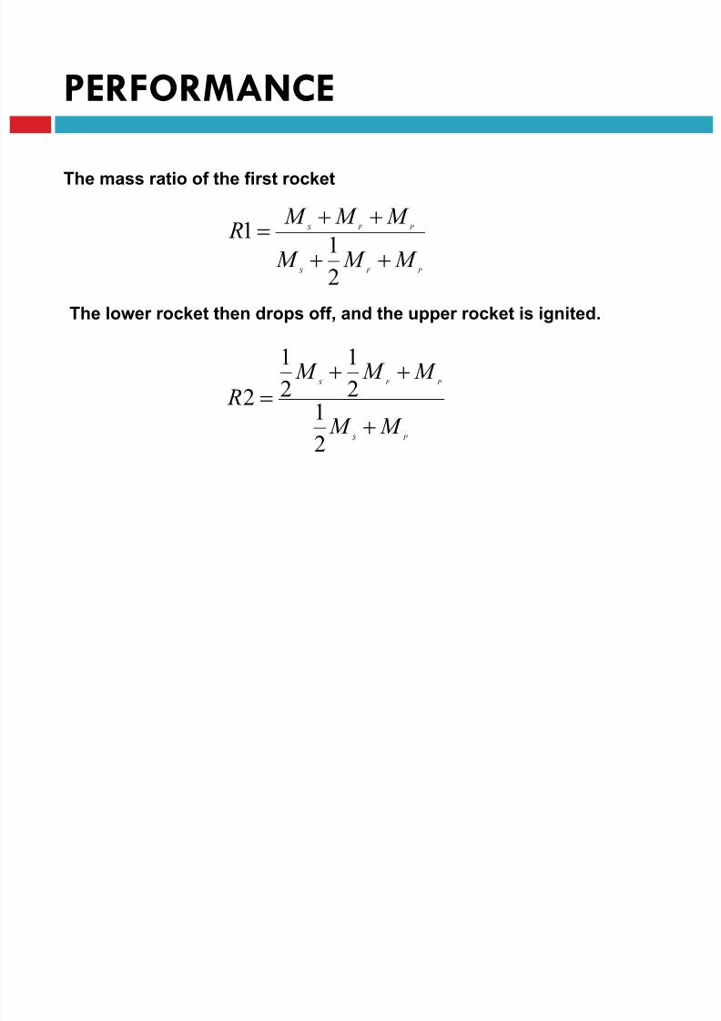
PERFORMANCE
P F S
P F S
M M M
M M M R
2
11
The mass ratio of the first rocket
The lower rocket then drops off, and the upper rocket is ignited.
P S
P F S
M M
M M M R
2
12
1
2
1
2
8/23/2019 Sdac Lec 9 10 Space Propulsion
http://slidepdf.com/reader/full/sdac-lec-9-10-space-propulsion 84/239
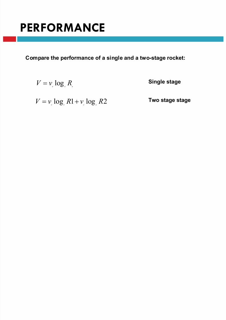
PERFORMANCE
Compare the performance of a single and a two-stage rocket:
oee RvV log
2log1log Rv RvV eeee
Two stage stage
Single stage

8/23/2019 Sdac Lec 9 10 Space Propulsion
http://slidepdf.com/reader/full/sdac-lec-9-10-space-propulsion 85/239
PERFORMANCE
Calculation :
A rocket of total mass 100 ton
Mass of spacecraft of 1 ton
Exhaust velocity of 2,700 m/sStructural mass is 10% of the fuel mass.
Single stage
Ro = 9.09

8/23/2019 Sdac Lec 9 10 Space Propulsion
http://slidepdf.com/reader/full/sdac-lec-9-10-space-propulsion 86/239
PERFORMANCE
Two stage stage
velocity of the first stage
R1 = 9.09
velocity increment of the second stage
R1 = 8.42

8/23/2019 Sdac Lec 9 10 Space Propulsion
http://slidepdf.com/reader/full/sdac-lec-9-10-space-propulsion 87/239
PERFORMANCE
Total velocity = 7342 m/s ;
1383 m/s more than what was achieved for single stage
Perform the same calculation for 3 and 4 stage vehicles with same data
Definitions
8/23/2019 Sdac Lec 9 10 Space Propulsion
http://slidepdf.com/reader/full/sdac-lec-9-10-space-propulsion 88/239
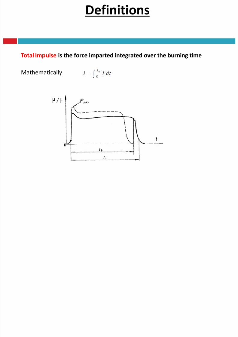
Total Impulse is the force imparted integrated over the burning time
Mathematically
Definitions

8/23/2019 Sdac Lec 9 10 Space Propulsion
http://slidepdf.com/reader/full/sdac-lec-9-10-space-propulsion 89/239
Effective exhaust velocity
Assumptions
Cannot be uniform over entire nozzle area
Measurement can be very difficult (velocity profile)1-D behavior is assumed (Uniform over entire area)
Average equivalent velocity at which Propellant is ejected
Mathematically .
m
F g I c s
Definitions
8/23/2019 Sdac Lec 9 10 Space Propulsion
http://slidepdf.com/reader/full/sdac-lec-9-10-space-propulsion 90/239
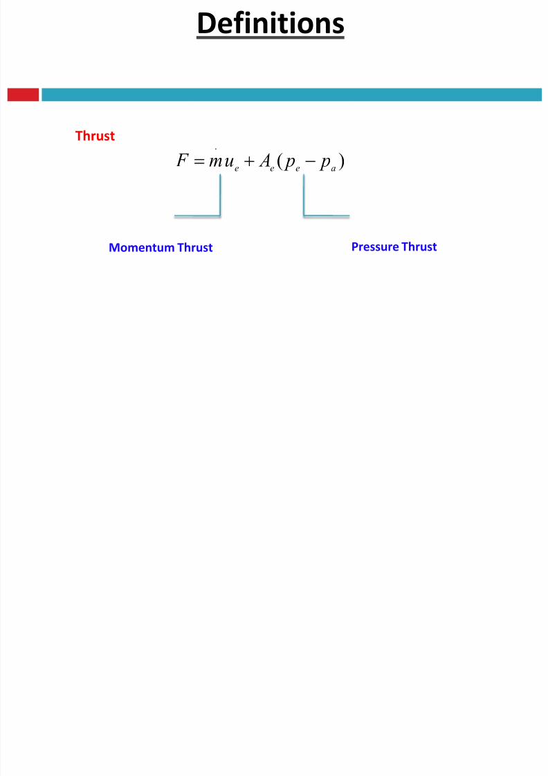
Thrust
)(.
aeeep p Aum F
Momentum Thrust Pressure Thrust
Definitions

8/23/2019 Sdac Lec 9 10 Space Propulsion
http://slidepdf.com/reader/full/sdac-lec-9-10-space-propulsion 91/239
Thrust
)(.
aeeep p Aum F Thrust equation
aep p
eum F
.
When
Characteristic Thrust
Definitions

8/23/2019 Sdac Lec 9 10 Space Propulsion
http://slidepdf.com/reader/full/sdac-lec-9-10-space-propulsion 92/239
Exhaust velocity
)(.
aeeep p Aum F Thrust equation
..
.
.
)(
m
p p A
m
um
m
F aeee
Dividing by mass flow rate
.
)(
m
p p Auc aee
e
Effective exhaust velocity
Definitions

8/23/2019 Sdac Lec 9 10 Space Propulsion
http://slidepdf.com/reader/full/sdac-lec-9-10-space-propulsion 93/239
Altitude performance of rocket engines
.)(
m
p p Auc aee
e
Variable PartFixed Part
Definitions
8/23/2019 Sdac Lec 9 10 Space Propulsion
http://slidepdf.com/reader/full/sdac-lec-9-10-space-propulsion 94/239
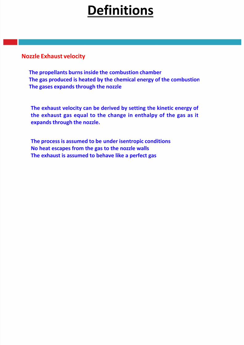
Nozzle Exhaust velocity
The propellants burns inside the combustion chamber
The gas produced is heated by the chemical energy of the combustion
The gases expands through the nozzle
The exhaust velocity can be derived by setting the kinetic energy of
the exhaust gas equal to the change in enthalpy of the gas as it
expands through the nozzle.
The process is assumed to be under isentropic conditions
No heat escapes from the gas to the nozzle walls
The exhaust is assumed to behave like a perfect gas

8/23/2019 Sdac Lec 9 10 Space Propulsion
http://slidepdf.com/reader/full/sdac-lec-9-10-space-propulsion 95/239
Nozzle Expansion

8/23/2019 Sdac Lec 9 10 Space Propulsion
http://slidepdf.com/reader/full/sdac-lec-9-10-space-propulsion 96/239
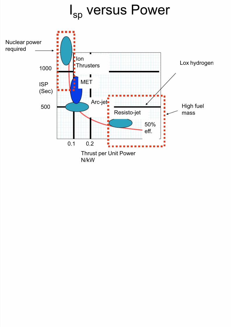
NOZZLE
Isp versus Power
8/23/2019 Sdac Lec 9 10 Space Propulsion
http://slidepdf.com/reader/full/sdac-lec-9-10-space-propulsion 97/239
Lox hydrogen
Nuclear power required
High fuel
mass
ISP(Sec)
Thrust per Unit Power
N/kW
0.1 0.2
1000
50%eff.
500Resisto-jet
Arc-jet
MET
Ion
Thrusters

8/23/2019 Sdac Lec 9 10 Space Propulsion
http://slidepdf.com/reader/full/sdac-lec-9-10-space-propulsion 98/239
Orbital transfer: Earth to Mars
• Start in low circular orbit do rocket
burn to give V (add energy)
• This puts one into transfer orbit that
is an ellipse
• At highest point of ellipse
(aphelion) one performs rocket
burn to add V to “circularize” orbit
at Mars(add more energy)
• To return one reverses theprocedure (subtract energy)
8/23/2019 Sdac Lec 9 10 Space Propulsion
http://slidepdf.com/reader/full/sdac-lec-9-10-space-propulsion 99/239
LECTURE # 9
SPACECRAFT PROPULSIONFUEL TYPES
8/23/2019 Sdac Lec 9 10 Space Propulsion
http://slidepdf.com/reader/full/sdac-lec-9-10-space-propulsion 100/239
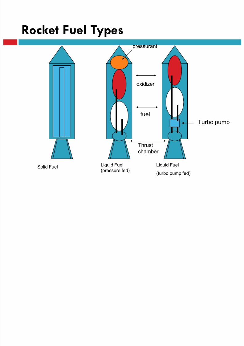
Rocket Fuel Types
Solid Fuel Liquid Fuel
(turbo pump fed)
Liquid Fuel
(pressure fed)
oxidizer
fuel
pressurant
Turbo pump
Thrust
chamber

8/23/2019 Sdac Lec 9 10 Space Propulsion
http://slidepdf.com/reader/full/sdac-lec-9-10-space-propulsion 101/239
ENERGY SOURCES

8/23/2019 Sdac Lec 9 10 Space Propulsion
http://slidepdf.com/reader/full/sdac-lec-9-10-space-propulsion 102/239
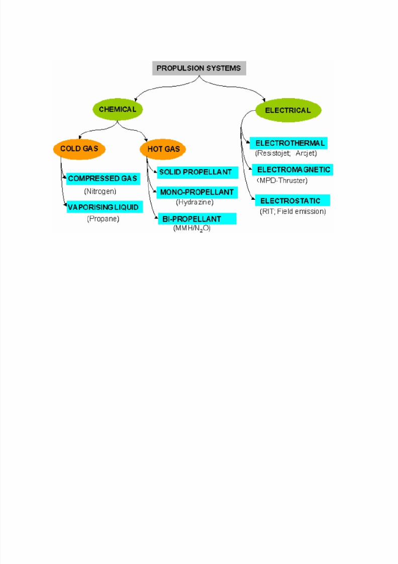
ENERGY SOURCES
Energy Source
Chemical Nuclear
Thermal
Electric
Solar
Thermal
Thermal
8/23/2019 Sdac Lec 9 10 Space Propulsion
http://slidepdf.com/reader/full/sdac-lec-9-10-space-propulsion 103/239
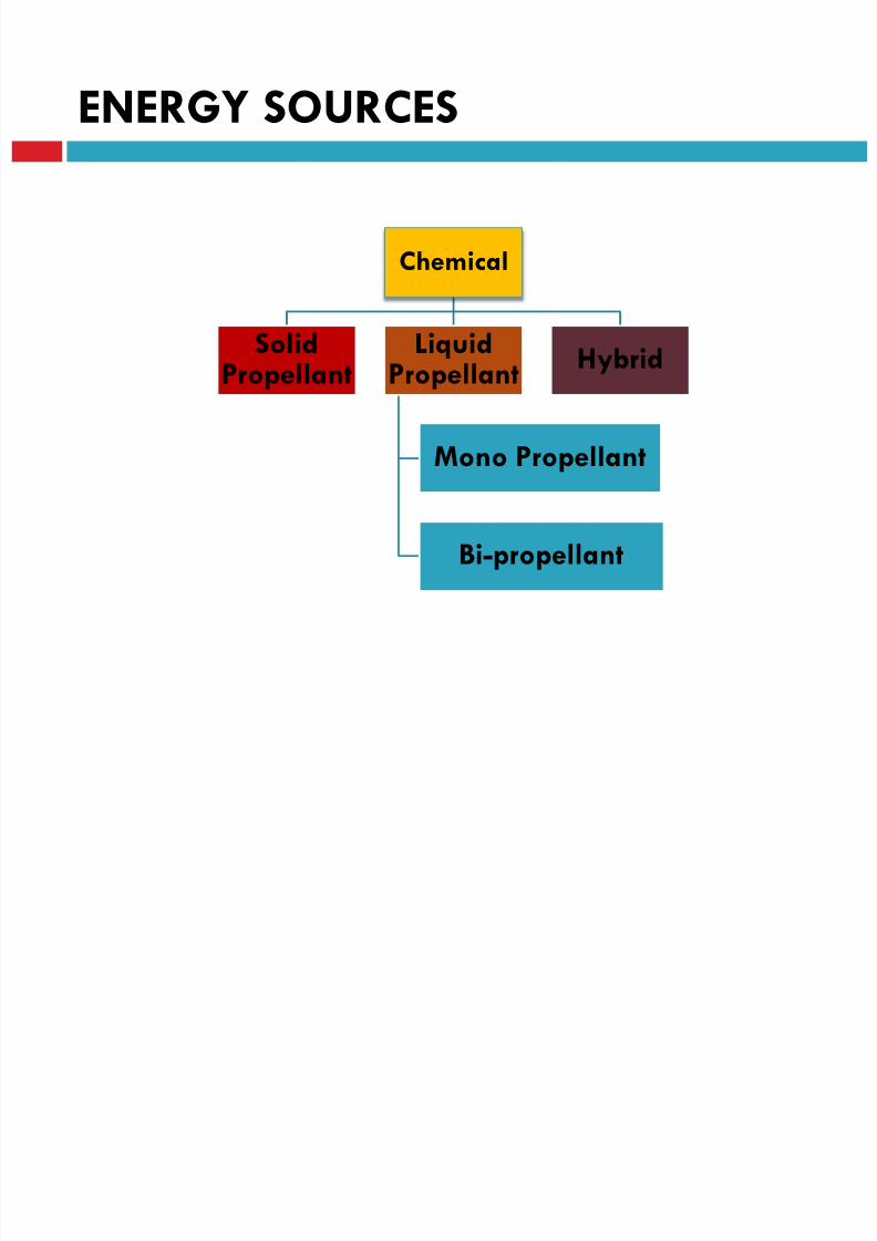
ENERGY SOURCES
Chemical
SolidPropellant
LiquidPropellant
Mono Propellant
Bi-propellant
Hybrid

8/23/2019 Sdac Lec 9 10 Space Propulsion
http://slidepdf.com/reader/full/sdac-lec-9-10-space-propulsion 104/239
8/23/2019 Sdac Lec 9 10 Space Propulsion
http://slidepdf.com/reader/full/sdac-lec-9-10-space-propulsion 105/239

8/23/2019 Sdac Lec 9 10 Space Propulsion
http://slidepdf.com/reader/full/sdac-lec-9-10-space-propulsion 106/239
LECTURE # 9
SPACECRAFT PROPULSIONSOLID FUEL
8/23/2019 Sdac Lec 9 10 Space Propulsion
http://slidepdf.com/reader/full/sdac-lec-9-10-space-propulsion 107/239
Solid Fuel Rockets
Solid Fuel
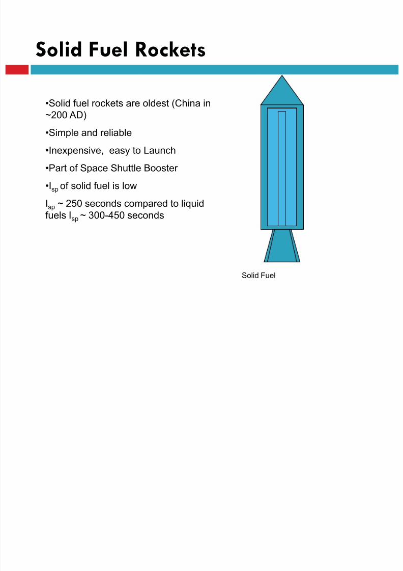
•Solid fuel rockets are oldest (China in
~200 AD)
•Simple and reliable
•Inexpensive, easy to Launch
•Part of Space Shuttle Booster
•Isp of solid fuel is low
Isp ~ 250 seconds compared to liquid
fuels Isp ~ 300-450 seconds

8/23/2019 Sdac Lec 9 10 Space Propulsion
http://slidepdf.com/reader/full/sdac-lec-9-10-space-propulsion 108/239
Solid fuels
•Solid fuels consist of a solid oxidizer plus a fuel example
•Oldest solid fuel Black Powder
•Saltpeter (KNO3) + Carbon+ Sulfur
•Oxidizer : KNO3 ( releases oxygen)
•Fuel : Carbon (burns with oxygen)
•Burn accelerator: Sulfur ( combines with left over potassium,
releasing more oxygen)

8/23/2019 Sdac Lec 9 10 Space Propulsion
http://slidepdf.com/reader/full/sdac-lec-9-10-space-propulsion 109/239
SRM

8/23/2019 Sdac Lec 9 10 Space Propulsion
http://slidepdf.com/reader/full/sdac-lec-9-10-space-propulsion 110/239
SRM
In solid propellant rockets , the word "motor" is used.
The propellant is contained and stored directly in the combustion
chamber
long-time storage (5 to 20 years).
Motors come in many different types and sizes, varying in thrust
from about 2 N to over 4 million N
Solid propellant rocket motors have been credited with having no
moving parts
8/23/2019 Sdac Lec 9 10 Space Propulsion
http://slidepdf.com/reader/full/sdac-lec-9-10-space-propulsion 111/239
SRM
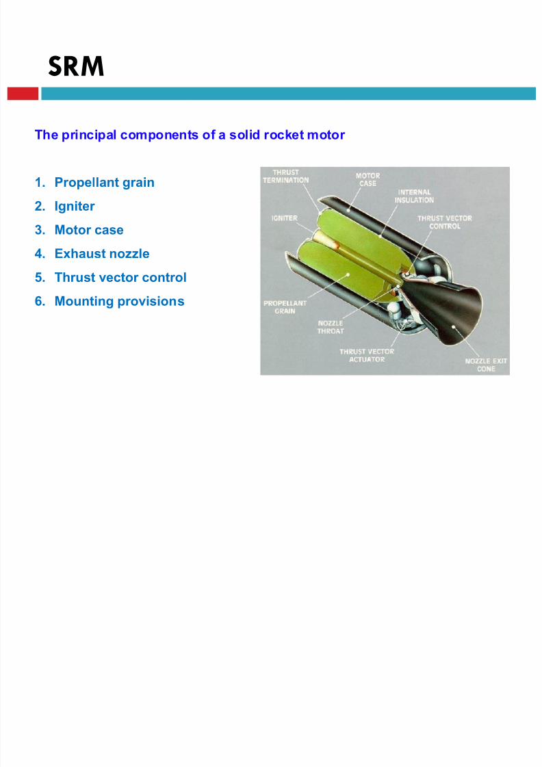
The principal components of a solid rocket motor
1. Propellant grain
2. Igniter
3. Motor case
4. Exhaust nozzle
5. Thrust vector control
6. Mounting provisions
8/23/2019 Sdac Lec 9 10 Space Propulsion
http://slidepdf.com/reader/full/sdac-lec-9-10-space-propulsion 112/239
SRM

8/23/2019 Sdac Lec 9 10 Space Propulsion
http://slidepdf.com/reader/full/sdac-lec-9-10-space-propulsion 113/239
SRM Classification
Basis of Classification Examples of Classification
Application Satellite boosters, ballistic missiles, sounding
rockets
Diameter 0.025 to 6.6m
Length 0.025 to 45m
Propellant Composite, double-base, Composite-modified
double-base
Case design Steel monolithic, fiber monolithic, segmented
Grain installation Case-bonded, Cartridge-loaded
Grain configuration Cylindrical, Spherical, end burning , 3D
8/23/2019 Sdac Lec 9 10 Space Propulsion
http://slidepdf.com/reader/full/sdac-lec-9-10-space-propulsion 114/239
Grain Configuration
Grain Configuration
Grain configuration basically is a geometrical consideration that
is going to impose a certain thrust law, thrust versus time, which
in turn is going to satisfy the ballistic performance requirement
for a specific mission
Grain is the shape of propellant mass inside
the rocket motor. The propellant grain is a
cast, molded, or extruded body, once ignited,
burns on all exposed surfaces to form hot
gases
G i C fi i
8/23/2019 Sdac Lec 9 10 Space Propulsion
http://slidepdf.com/reader/full/sdac-lec-9-10-space-propulsion 115/239
Grain Configurations
A variety of grain configurations are available depending upon
the available propellant
Two dimensional as well as three dimensional configuration can
be selected depending on specific requirements
1. Star
2. Slotted tube
3. Wagon wheel
4. Three dimensional grain
8/23/2019 Sdac Lec 9 10 Space Propulsion
http://slidepdf.com/reader/full/sdac-lec-9-10-space-propulsion 116/239

8/23/2019 Sdac Lec 9 10 Space Propulsion
http://slidepdf.com/reader/full/sdac-lec-9-10-space-propulsion 117/239

8/23/2019 Sdac Lec 9 10 Space Propulsion
http://slidepdf.com/reader/full/sdac-lec-9-10-space-propulsion 118/239
LECTURE # 9
SPACECRAFT PROPULSION
LIQUID FUEL
LIQUID ROCKET ENGINE

8/23/2019 Sdac Lec 9 10 Space Propulsion
http://slidepdf.com/reader/full/sdac-lec-9-10-space-propulsion 119/239
LIQUID ROCKET ENGINE
The mission requirements can be translated into rocket enginerequirements in terms of
Thrust-time profile
Propellants
Number of thrust chambers
Total impulse
Number of restarts
Minimum reliability
Engine masses and their sizes or envelopes
LIQUID ROCKET ENGINE
8/23/2019 Sdac Lec 9 10 Space Propulsion
http://slidepdf.com/reader/full/sdac-lec-9-10-space-propulsion 120/239
LIQUID ROCKET ENGINE
The design of any propulsion system is tailored to fit a specific
application or mission requirement
Application Mission velocity
The desired flight trajectories
orbit transfer Vulnerability
Attitude control torques Duty cycle
Minimum life (during storage or in orbit)
Number of units to be built and delivered. They include
constraints on cost, schedule, operating conditions,
storage conditions, or safety rules
LIQUID ROCKET ENGINE
8/23/2019 Sdac Lec 9 10 Space Propulsion
http://slidepdf.com/reader/full/sdac-lec-9-10-space-propulsion 121/239
LIQUID ROCKET ENGINE
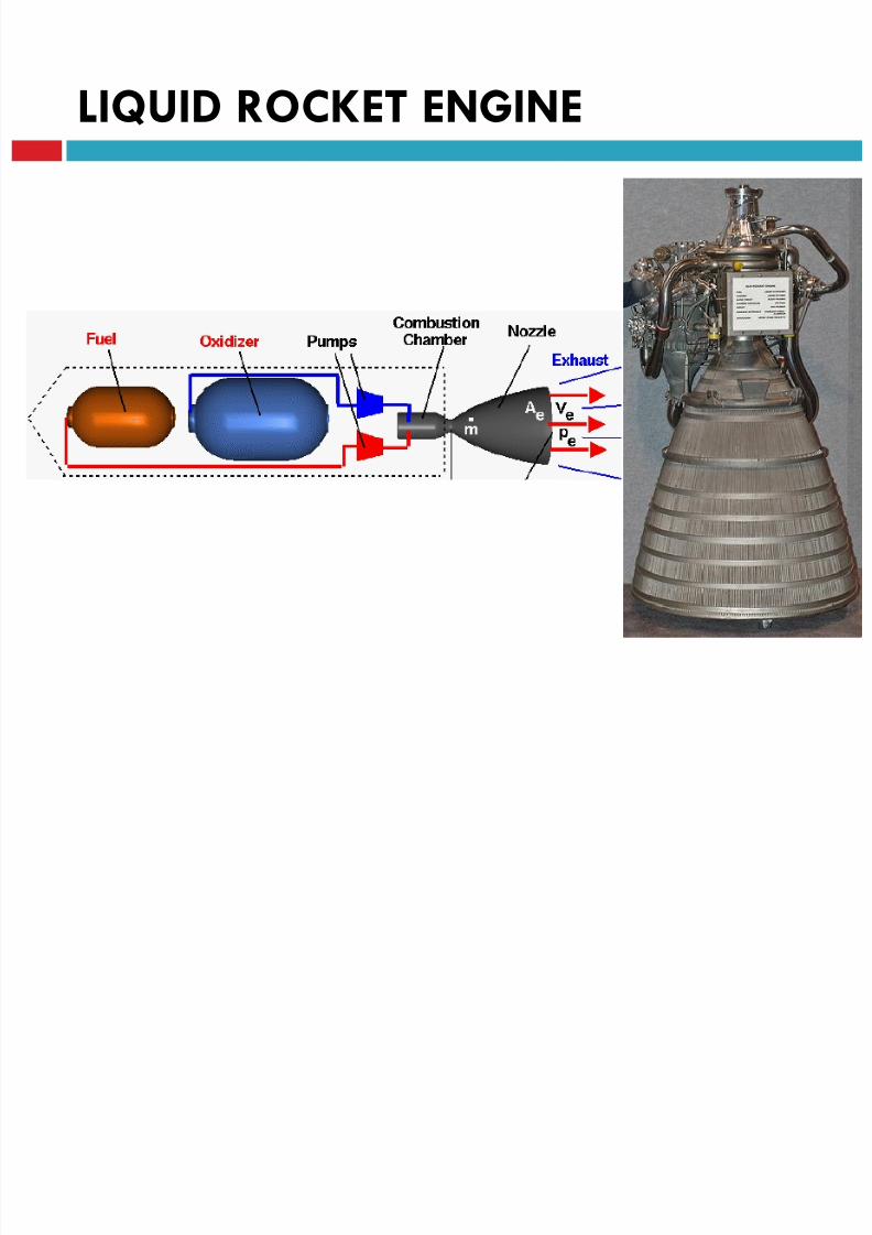
A liquid propellant rocket propulsion system is commonly
called a rocket engine
One or more thrust chambers
One or more tanks to store the propellants
A feed mechanism to force the propellants from the tanks into the thrust
chamber(s)
A power source to furnish the energy for the feed mechanism
Suitable plumbing or piping to transfer the liquids
A structure to transmit the thrust force
Control devices to initiate and regulate the propellant flow and thus the
thrust.
LIQUID ROCKET ENGINE
8/23/2019 Sdac Lec 9 10 Space Propulsion
http://slidepdf.com/reader/full/sdac-lec-9-10-space-propulsion 122/239
LIQUID ROCKET ENGINE
LIQUID ROCKET ENGINE

8/23/2019 Sdac Lec 9 10 Space Propulsion
http://slidepdf.com/reader/full/sdac-lec-9-10-space-propulsion 123/239
LIQUID ROCKET ENGINE
Many different types of rocket engines have been built and flown
Thrust size from less than 0.01 lbf to over 1.75 million pounds
One-time operation or multiple starts (some have over 150,000 restarts)
With or without thrust modulation (called throttling)
Single use or reusable
Arranged as single engines or in clusters of multiple units
LIQUID ROCKET ENGINE
8/23/2019 Sdac Lec 9 10 Space Propulsion
http://slidepdf.com/reader/full/sdac-lec-9-10-space-propulsion 124/239
LIQUID ROCKET ENGINE
The thrust chamber or thruster is the combustion device wherethe liquid propellants
Metered
Injected
AtomizedMixed
Burned to form hot gaseous reaction products
Hot gaseous are accelerated and ejected at a high velocity to
impart a thrust force
A thrust chamber has three major parts:
An injector
A combustion chamber
A nozzle
LIQUID ROCKET ENGINE
8/23/2019 Sdac Lec 9 10 Space Propulsion
http://slidepdf.com/reader/full/sdac-lec-9-10-space-propulsion 125/239
LIQUID ROCKET ENGINE
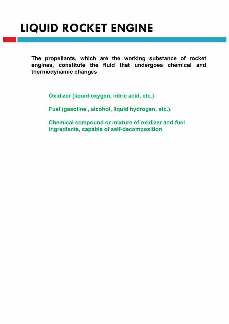
The propellants, which are the working substance of rocket
engines, constitute the fluid that undergoes chemical and
thermodynamic changes
Oxidizer (liquid oxygen, nitric acid, etc.)
Fuel (gasoline , alcohol, liquid hydrogen, etc.).
Chemical compound or mixture of oxidizer and fuelingredients, capable of self-decomposition
LIQUID ROCKET ENGINE
8/23/2019 Sdac Lec 9 10 Space Propulsion
http://slidepdf.com/reader/full/sdac-lec-9-10-space-propulsion 126/239
LIQUID ROCKET ENGINE
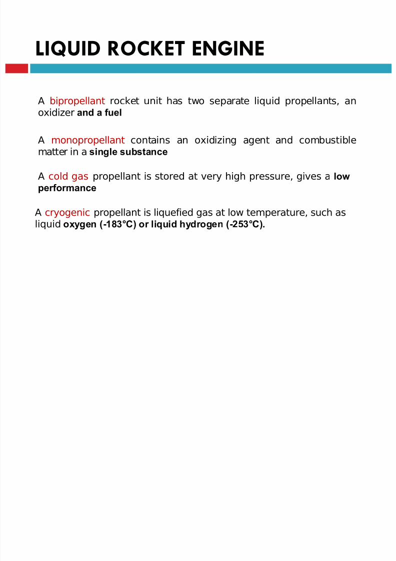
A bipropellant rocket unit has two separate liquid propellants, anoxidizer and a fuel
A monopropellant contains an oxidizing agent and combustiblematter in a single substance
A cold gas propellant is stored at very high pressure, gives a low
performance
A cryogenic propellant is liquefied gas at low temperature, such asliquid oxygen (-183°C) or liquid hydrogen (-253°C).
Li id F l (t b )
8/23/2019 Sdac Lec 9 10 Space Propulsion
http://slidepdf.com/reader/full/sdac-lec-9-10-space-propulsion 127/239
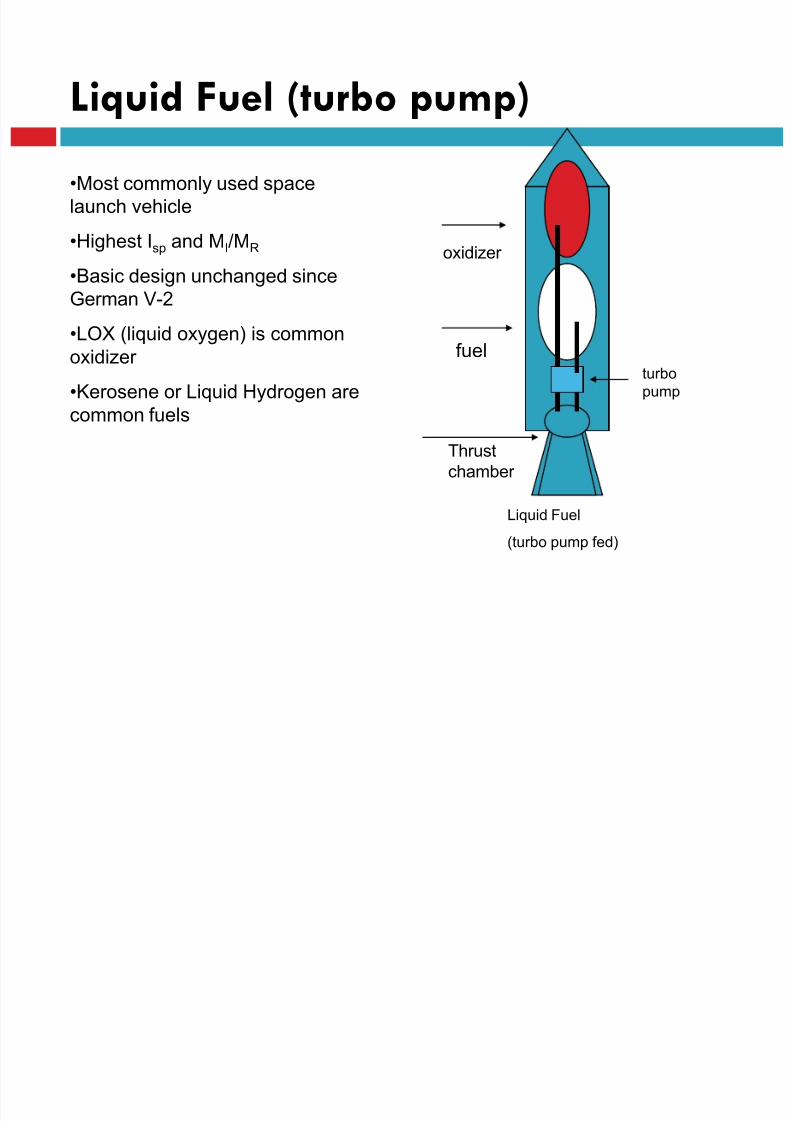
Liquid Fuel (turbo pump)
Liquid Fuel
(turbo pump fed)
oxidizer
fuel
Thrust
chamber
•Most commonly used space
launch vehicle
•Highest Isp and MI/MR
•Basic design unchanged since
German V-2
•LOX (liquid oxygen) is common
oxidizer
•Kerosene or Liquid Hydrogen are
common fuels
turbo
pump
Liquid Fuels

8/23/2019 Sdac Lec 9 10 Space Propulsion
http://slidepdf.com/reader/full/sdac-lec-9-10-space-propulsion 128/239
•Liquid fuels have lower average molecular
weight exhaust than solid fuels
•They can be burned in thrust chamber of
fixed geometry to maximize performance
•The liquid can be pure cryogenic gases
such as oxygen and hydrogen

8/23/2019 Sdac Lec 9 10 Space Propulsion
http://slidepdf.com/reader/full/sdac-lec-9-10-space-propulsion 129/239
LECTURE # 9
SPACECRAFT PROPULSION
HYBRID
HYBRID FUEL
8/23/2019 Sdac Lec 9 10 Space Propulsion
http://slidepdf.com/reader/full/sdac-lec-9-10-space-propulsion 130/239
HYBRID FUEL

8/23/2019 Sdac Lec 9 10 Space Propulsion
http://slidepdf.com/reader/full/sdac-lec-9-10-space-propulsion 131/239
LECTURE # 9
SPACECRAFT PROPULSION
OTHERS
8/23/2019 Sdac Lec 9 10 Space Propulsion
http://slidepdf.com/reader/full/sdac-lec-9-10-space-propulsion 132/239
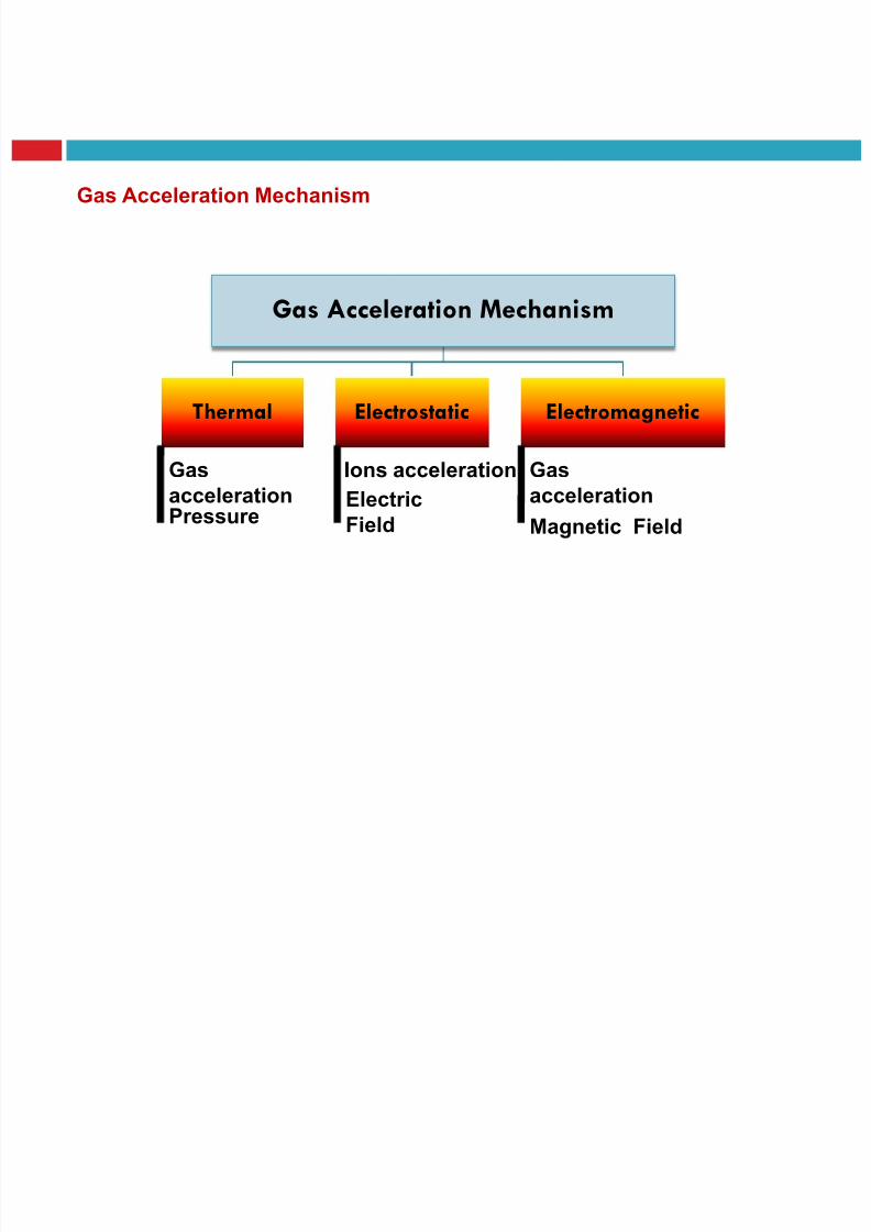
Gas Acceleration Mechanism
Gas Acceleration Mechanism
Thermal Electrostatic Electromagnetic
PressureElectric
Field
Gasacceleration
Ions acceleration
Magnetic Field
Gasacceleration
ION THRUSTER

8/23/2019 Sdac Lec 9 10 Space Propulsion
http://slidepdf.com/reader/full/sdac-lec-9-10-space-propulsion 133/239
ION THRUSTER
Electromagnetic Propulsion

8/23/2019 Sdac Lec 9 10 Space Propulsion
http://slidepdf.com/reader/full/sdac-lec-9-10-space-propulsion 134/239
Electromagnetic Propulsion
NUCLEAR
8/23/2019 Sdac Lec 9 10 Space Propulsion
http://slidepdf.com/reader/full/sdac-lec-9-10-space-propulsion 135/239
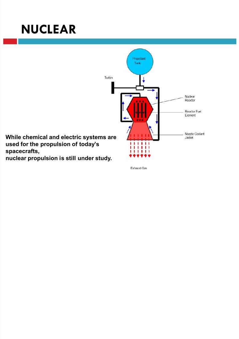
NUCLEAR
While chemical and electric systems are
used for the propulsion of today’s
spacecrafts,
nuclear propulsion is still under study.
8/23/2019 Sdac Lec 9 10 Space Propulsion
http://slidepdf.com/reader/full/sdac-lec-9-10-space-propulsion 136/239
LECTURE # 9
SPACECRAFT PROPULSION
ELECTRIC
Electric Propulsion
8/23/2019 Sdac Lec 9 10 Space Propulsion
http://slidepdf.com/reader/full/sdac-lec-9-10-space-propulsion 137/239
Electric Propulsion
Electric Propulsion

8/23/2019 Sdac Lec 9 10 Space Propulsion
http://slidepdf.com/reader/full/sdac-lec-9-10-space-propulsion 138/239
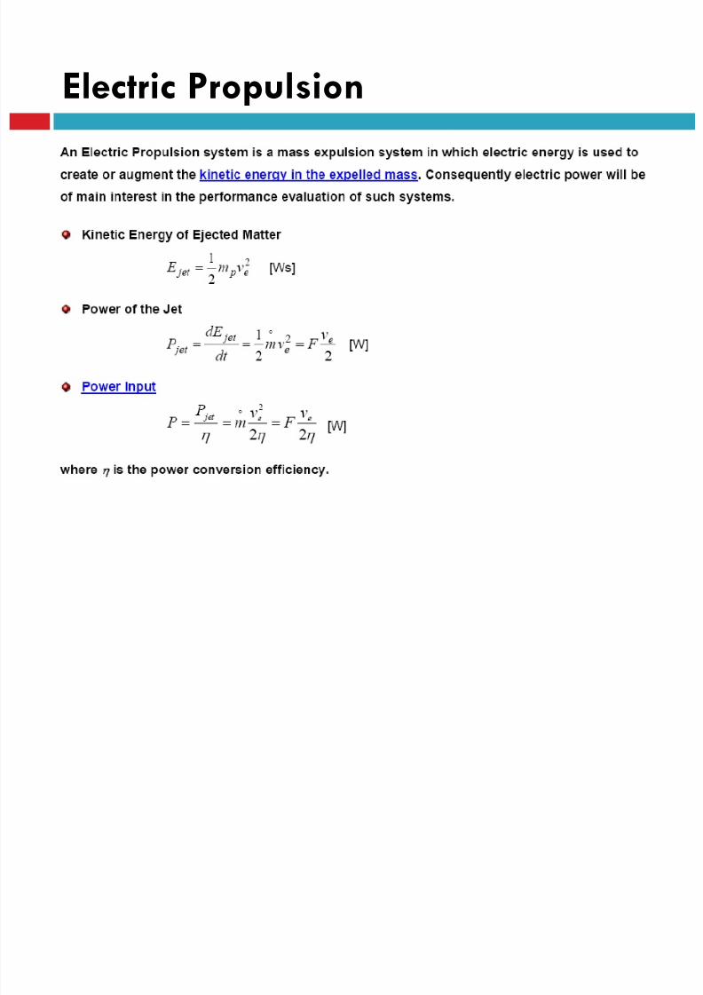
Electric Propulsion
• Electric propulsion heats or accelerates gases electrically to
achieve higher Isp than possible with chemical combustion
•Electro thermal uses electric arcs to heat gas to welding arc
temperatures
•Ion thrusters electrically accelerate ionized gas to high velocity
Electric Propulsion
8/23/2019 Sdac Lec 9 10 Space Propulsion
http://slidepdf.com/reader/full/sdac-lec-9-10-space-propulsion 139/239
Electric Propulsion
Electric Propulsion

8/23/2019 Sdac Lec 9 10 Space Propulsion
http://slidepdf.com/reader/full/sdac-lec-9-10-space-propulsion 140/239
Electric Propulsion
Electric Propulsion
8/23/2019 Sdac Lec 9 10 Space Propulsion
http://slidepdf.com/reader/full/sdac-lec-9-10-space-propulsion 141/239
Electric Propulsion
Electric Propulsion
8/23/2019 Sdac Lec 9 10 Space Propulsion
http://slidepdf.com/reader/full/sdac-lec-9-10-space-propulsion 142/239
Electric Propulsion
ELECTROTHERMAL SYSTEMS

8/23/2019 Sdac Lec 9 10 Space Propulsion
http://slidepdf.com/reader/full/sdac-lec-9-10-space-propulsion 143/239
ELECTROTHERMAL SYSTEMS
ELECTROTHERMAL SYSTEMS
8/23/2019 Sdac Lec 9 10 Space Propulsion
http://slidepdf.com/reader/full/sdac-lec-9-10-space-propulsion 144/239
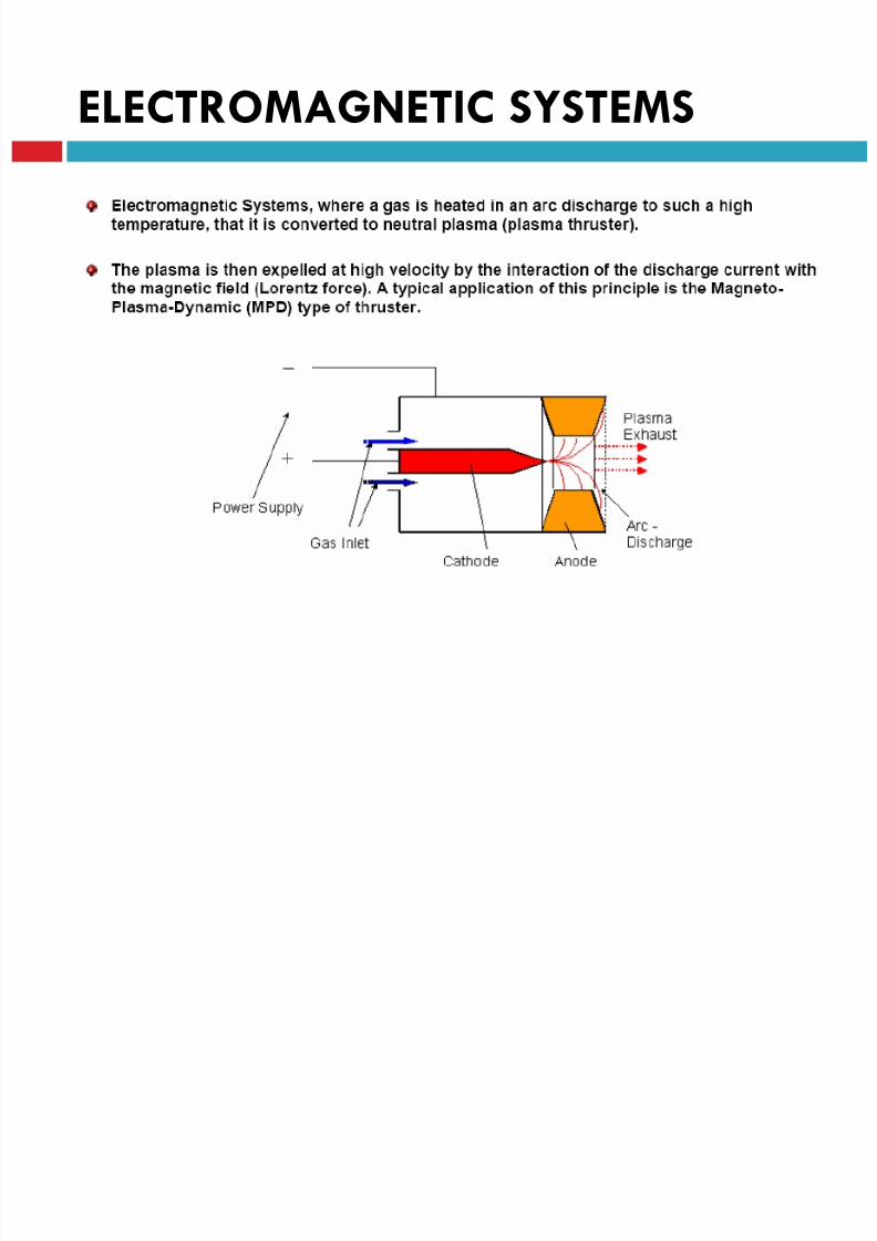
ELECTROTHERMAL SYSTEMS
ELECTROMAGNETIC SYSTEMS
8/23/2019 Sdac Lec 9 10 Space Propulsion
http://slidepdf.com/reader/full/sdac-lec-9-10-space-propulsion 145/239
ELECTROMAGNETIC SYSTEMS
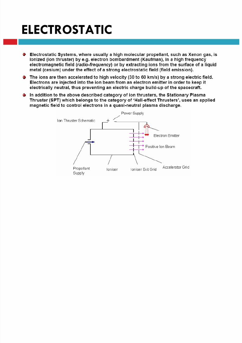
ELECTROSTATIC
8/23/2019 Sdac Lec 9 10 Space Propulsion
http://slidepdf.com/reader/full/sdac-lec-9-10-space-propulsion 146/239
ELECTROSTATIC
8/23/2019 Sdac Lec 9 10 Space Propulsion
http://slidepdf.com/reader/full/sdac-lec-9-10-space-propulsion 147/239
ELECTRIC Thrusters

8/23/2019 Sdac Lec 9 10 Space Propulsion
http://slidepdf.com/reader/full/sdac-lec-9-10-space-propulsion 148/239
ELECTRIC Thrusters

8/23/2019 Sdac Lec 9 10 Space Propulsion
http://slidepdf.com/reader/full/sdac-lec-9-10-space-propulsion 149/239
LECTURE # 9
SPACECRAFT PROPULSION
COLD GAS
Cold Gas

8/23/2019 Sdac Lec 9 10 Space Propulsion
http://slidepdf.com/reader/full/sdac-lec-9-10-space-propulsion 150/239
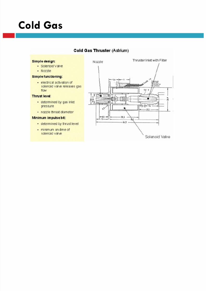
Cold Gas
Cold Gas
8/23/2019 Sdac Lec 9 10 Space Propulsion
http://slidepdf.com/reader/full/sdac-lec-9-10-space-propulsion 151/239
Cold Gas
Cold Gas

8/23/2019 Sdac Lec 9 10 Space Propulsion
http://slidepdf.com/reader/full/sdac-lec-9-10-space-propulsion 152/239
Cold Gas
Cold Gas
8/23/2019 Sdac Lec 9 10 Space Propulsion
http://slidepdf.com/reader/full/sdac-lec-9-10-space-propulsion 153/239
Cold Gas
Cold Gas
8/23/2019 Sdac Lec 9 10 Space Propulsion
http://slidepdf.com/reader/full/sdac-lec-9-10-space-propulsion 154/239
Cold Gas
Cold gas
8/23/2019 Sdac Lec 9 10 Space Propulsion
http://slidepdf.com/reader/full/sdac-lec-9-10-space-propulsion 155/239
g
Cold gas
8/23/2019 Sdac Lec 9 10 Space Propulsion
http://slidepdf.com/reader/full/sdac-lec-9-10-space-propulsion 156/239
g
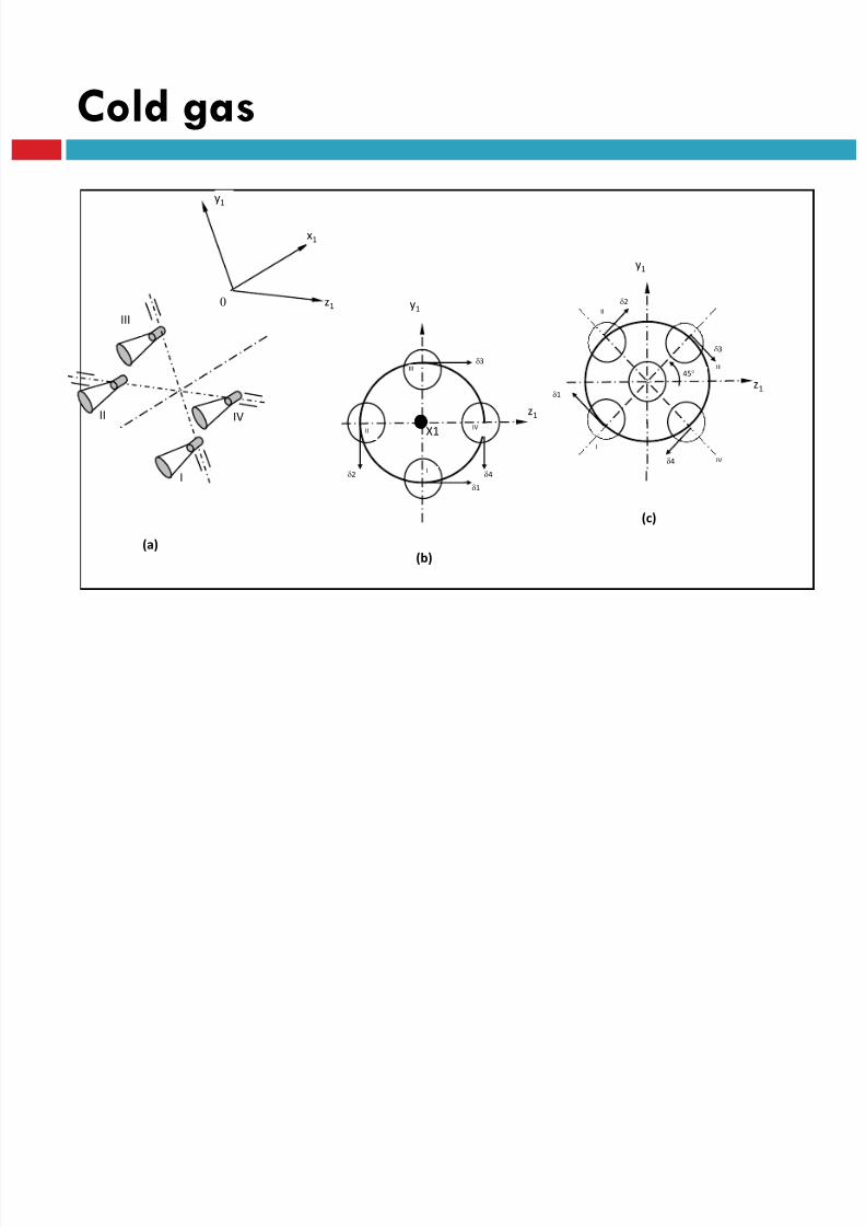
z1
x1
y1
0
II
III
IV
I
(a)
y1
II
I
III
IVX1
1
2 4
3
z1
(b)
II
I
III
IV
45
1
2
4
3
y1
z1
(c)

8/23/2019 Sdac Lec 9 10 Space Propulsion
http://slidepdf.com/reader/full/sdac-lec-9-10-space-propulsion 157/239
LECTURE # 9
SPACECRAFT PROPULSION
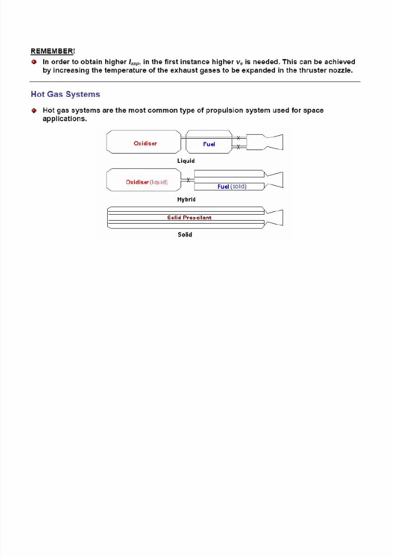
HOT GAS
8/23/2019 Sdac Lec 9 10 Space Propulsion
http://slidepdf.com/reader/full/sdac-lec-9-10-space-propulsion 158/239
8/23/2019 Sdac Lec 9 10 Space Propulsion
http://slidepdf.com/reader/full/sdac-lec-9-10-space-propulsion 159/239
Liquid Propellant
8/23/2019 Sdac Lec 9 10 Space Propulsion
http://slidepdf.com/reader/full/sdac-lec-9-10-space-propulsion 160/239
q p

8/23/2019 Sdac Lec 9 10 Space Propulsion
http://slidepdf.com/reader/full/sdac-lec-9-10-space-propulsion 161/239
LECTURE # 9
SPACECRAFT PROPULSION
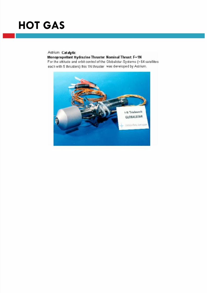
HOT GAS
MONOPROPELLANT SYSTEMS
MONOPROPELLANT SYSTEMS
8/23/2019 Sdac Lec 9 10 Space Propulsion
http://slidepdf.com/reader/full/sdac-lec-9-10-space-propulsion 162/239
MONOPROPELLANT SYSTEMS

8/23/2019 Sdac Lec 9 10 Space Propulsion
http://slidepdf.com/reader/full/sdac-lec-9-10-space-propulsion 163/239
HOT GAS
8/23/2019 Sdac Lec 9 10 Space Propulsion
http://slidepdf.com/reader/full/sdac-lec-9-10-space-propulsion 164/239
MONOPROPELLANT SYSTEMS

8/23/2019 Sdac Lec 9 10 Space Propulsion
http://slidepdf.com/reader/full/sdac-lec-9-10-space-propulsion 165/239

8/23/2019 Sdac Lec 9 10 Space Propulsion
http://slidepdf.com/reader/full/sdac-lec-9-10-space-propulsion 166/239
8/23/2019 Sdac Lec 9 10 Space Propulsion
http://slidepdf.com/reader/full/sdac-lec-9-10-space-propulsion 167/239

8/23/2019 Sdac Lec 9 10 Space Propulsion
http://slidepdf.com/reader/full/sdac-lec-9-10-space-propulsion 168/239

8/23/2019 Sdac Lec 9 10 Space Propulsion
http://slidepdf.com/reader/full/sdac-lec-9-10-space-propulsion 169/239
8/23/2019 Sdac Lec 9 10 Space Propulsion
http://slidepdf.com/reader/full/sdac-lec-9-10-space-propulsion 170/239

8/23/2019 Sdac Lec 9 10 Space Propulsion
http://slidepdf.com/reader/full/sdac-lec-9-10-space-propulsion 171/239

8/23/2019 Sdac Lec 9 10 Space Propulsion
http://slidepdf.com/reader/full/sdac-lec-9-10-space-propulsion 172/239
LECTURE # 9
SPACECRAFT PROPULSION
HOT GAS
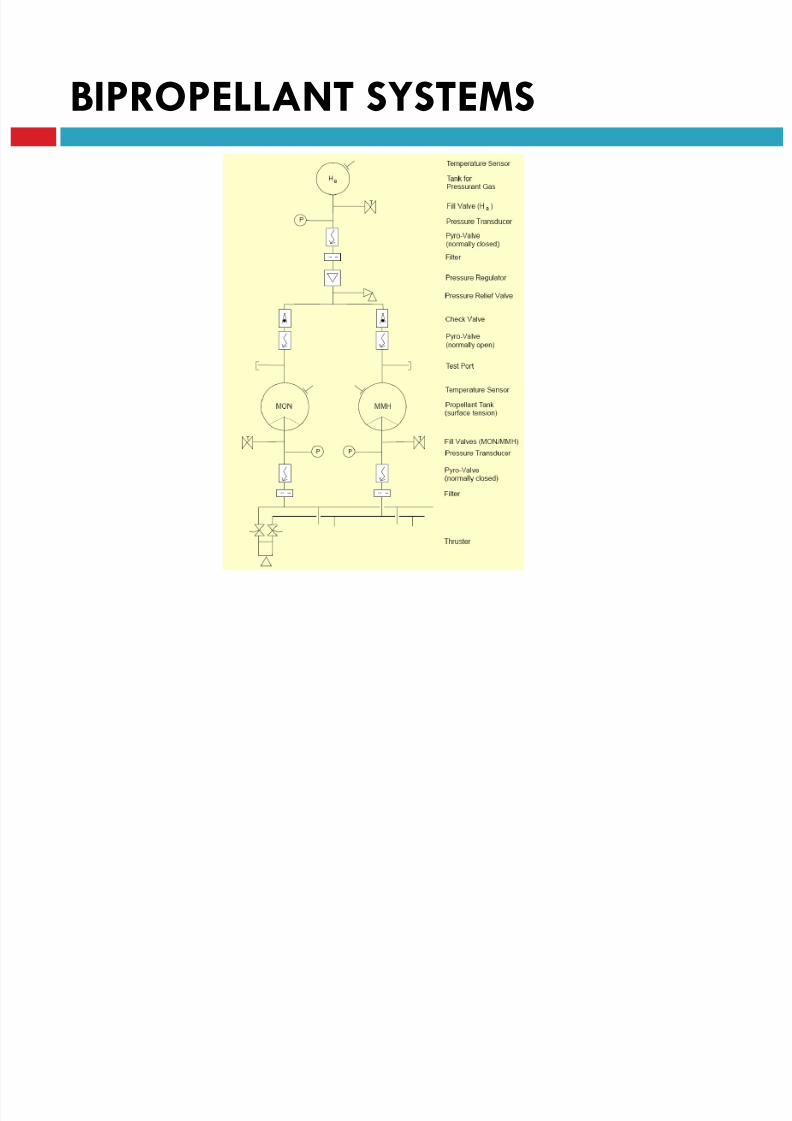
BIPROPELLANT SYSTEMS
BIPROPELLANT SYSTEMS

8/23/2019 Sdac Lec 9 10 Space Propulsion
http://slidepdf.com/reader/full/sdac-lec-9-10-space-propulsion 173/239
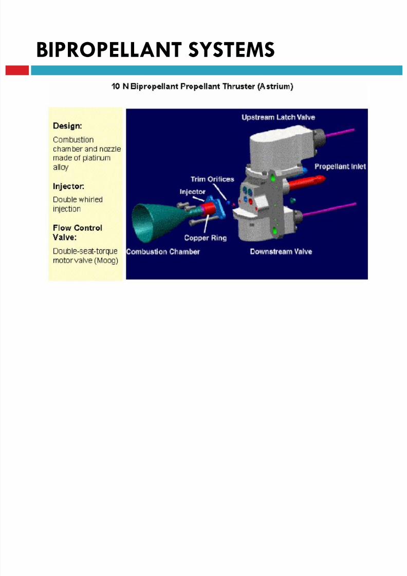
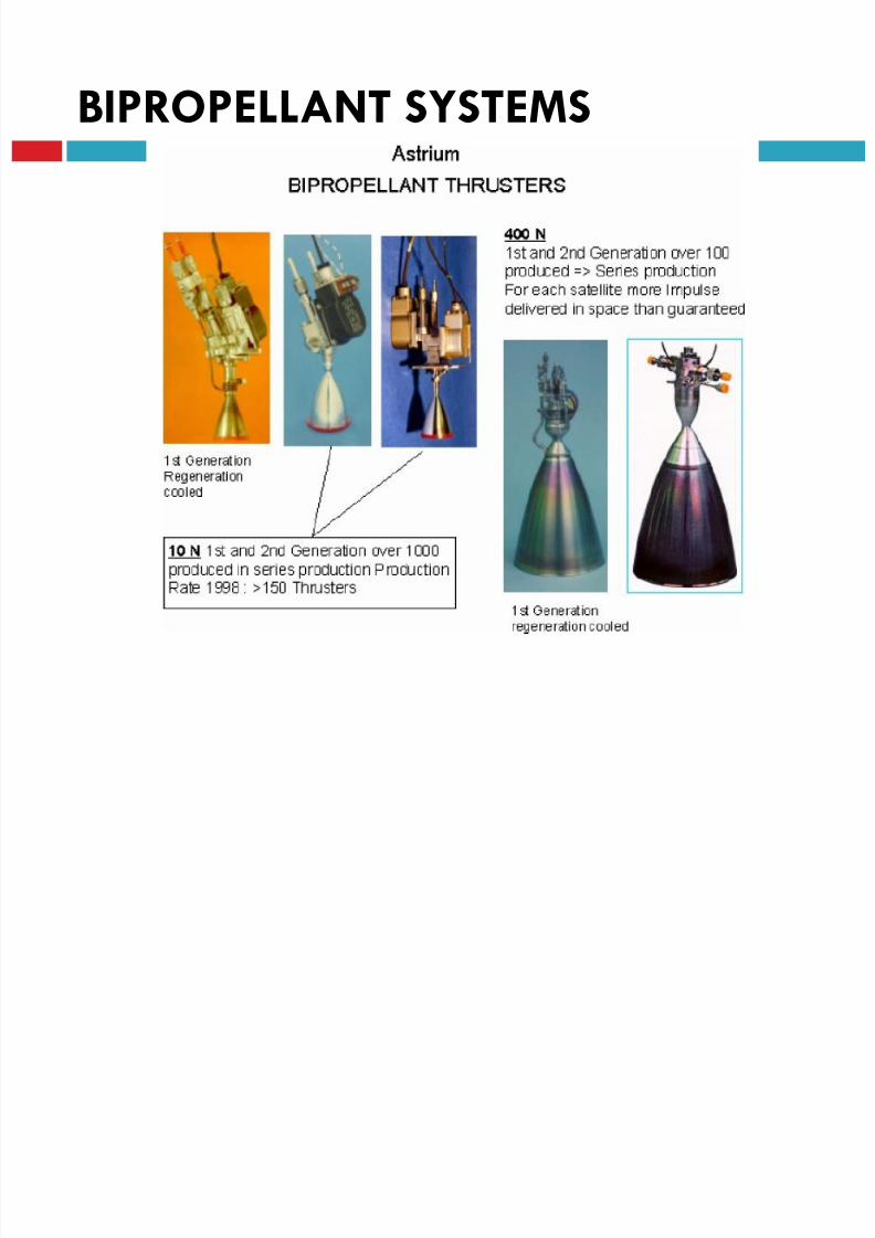
BIPROPELLANT SYSTEMS
8/23/2019 Sdac Lec 9 10 Space Propulsion
http://slidepdf.com/reader/full/sdac-lec-9-10-space-propulsion 174/239
BIPROPELLANT SYSTEMS

8/23/2019 Sdac Lec 9 10 Space Propulsion
http://slidepdf.com/reader/full/sdac-lec-9-10-space-propulsion 175/239
BIPROPELLANT SYSTEMS

8/23/2019 Sdac Lec 9 10 Space Propulsion
http://slidepdf.com/reader/full/sdac-lec-9-10-space-propulsion 176/239
BIPROPELLANT SYSTEMS
8/23/2019 Sdac Lec 9 10 Space Propulsion
http://slidepdf.com/reader/full/sdac-lec-9-10-space-propulsion 177/239
BIPROPELLANT SYSTEMS
8/23/2019 Sdac Lec 9 10 Space Propulsion
http://slidepdf.com/reader/full/sdac-lec-9-10-space-propulsion 178/239

8/23/2019 Sdac Lec 9 10 Space Propulsion
http://slidepdf.com/reader/full/sdac-lec-9-10-space-propulsion 179/239
8/23/2019 Sdac Lec 9 10 Space Propulsion
http://slidepdf.com/reader/full/sdac-lec-9-10-space-propulsion 180/239
LECTURE # 9
SPACECRAFT PROPULSION
HOT GAS
PROPELLANT TANKS
Propellant Tanks
8/23/2019 Sdac Lec 9 10 Space Propulsion
http://slidepdf.com/reader/full/sdac-lec-9-10-space-propulsion 181/239
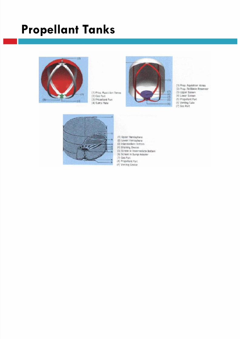
Propellant Tanks

8/23/2019 Sdac Lec 9 10 Space Propulsion
http://slidepdf.com/reader/full/sdac-lec-9-10-space-propulsion 182/239
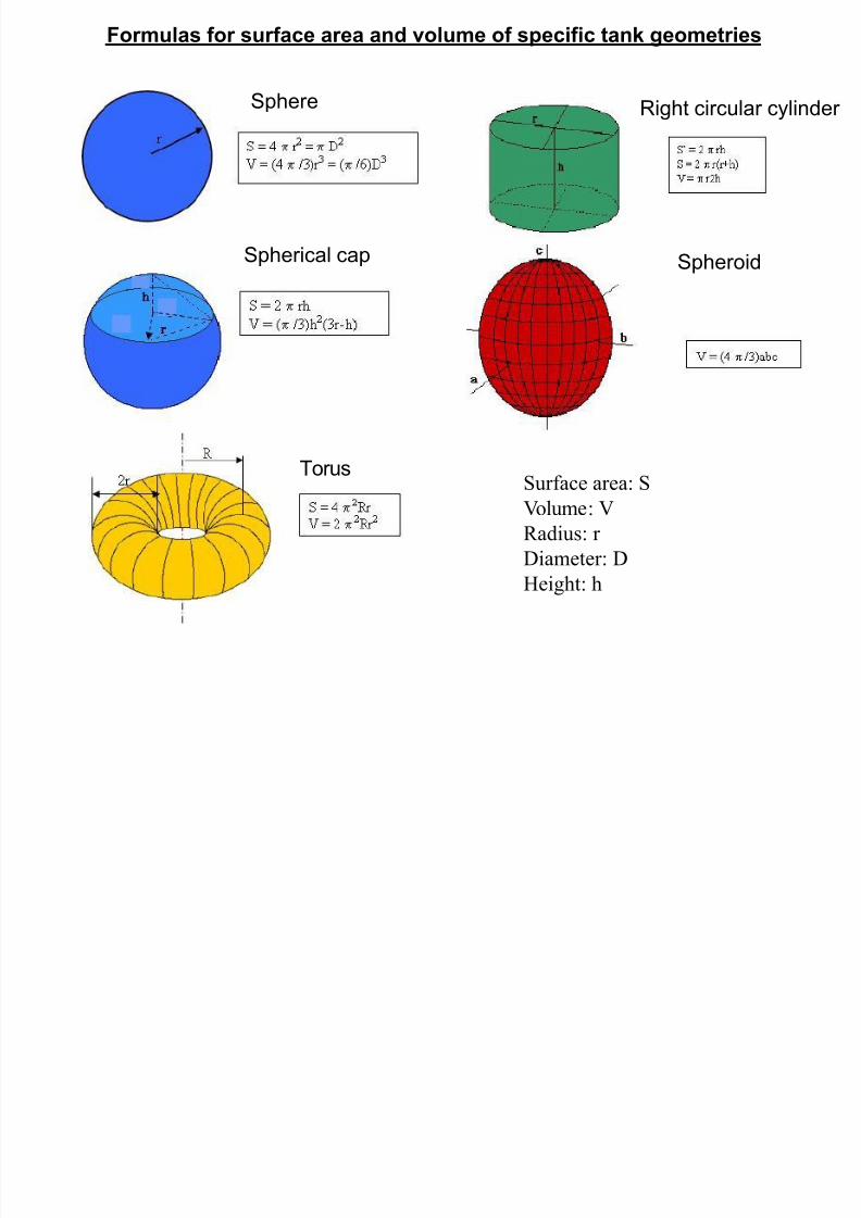
Sphere Right circular cylinder
Formulas for surface area and volume of specific tank geometries
8/23/2019 Sdac Lec 9 10 Space Propulsion
http://slidepdf.com/reader/full/sdac-lec-9-10-space-propulsion 183/239
Surface area: S
Volume: V
Radius: r
Diameter: D
Height: h
Spherical cap Spheroid
Torus

8/23/2019 Sdac Lec 9 10 Space Propulsion
http://slidepdf.com/reader/full/sdac-lec-9-10-space-propulsion 184/239
LECTURE # 9
SPACECRAFT PROPULSION
APPLICATIONS
THRUST LEVEL
8/23/2019 Sdac Lec 9 10 Space Propulsion
http://slidepdf.com/reader/full/sdac-lec-9-10-space-propulsion 185/239
High thrust : for launch, missiles etc
Low thrust : for efficient in-space maneuvers
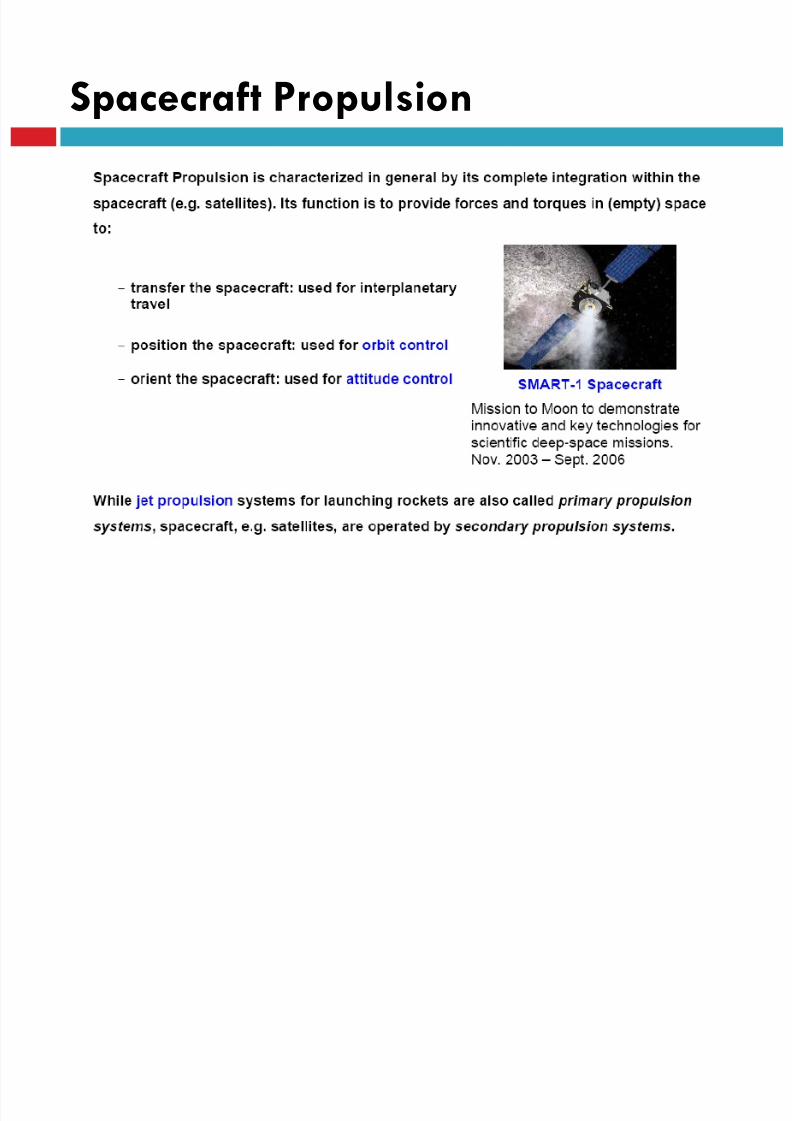
Spacecraft Propulsion
8/23/2019 Sdac Lec 9 10 Space Propulsion
http://slidepdf.com/reader/full/sdac-lec-9-10-space-propulsion 186/239
Characteristics ofSpace Propulsion Systems

8/23/2019 Sdac Lec 9 10 Space Propulsion
http://slidepdf.com/reader/full/sdac-lec-9-10-space-propulsion 187/239
Characteristics ofSpace Propulsion Systems

8/23/2019 Sdac Lec 9 10 Space Propulsion
http://slidepdf.com/reader/full/sdac-lec-9-10-space-propulsion 188/239
Impulse bits
Impulse bit is the smallest change in momentum required to allow for e.g. fine
attitude and orbit control of a spacecraft.
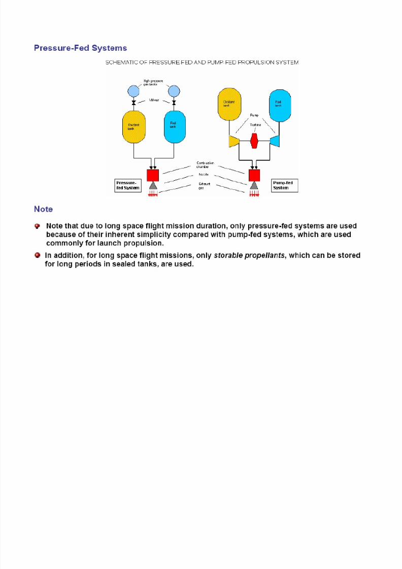
Storable propellants
Storable Propellants are liquid (or gaseous) at ambient temperature and can
be stored for long periods in sealed tanks, e.g. monopropellant hydrazine
In contrast, cryogenic propellants, which are liquefied gases at low
temperature, such as liquid oxygen (-147 °C) or liquid hydrogen (-253 °C) are
difficult to be used for long space flight missions.
Note: at present only storable propellants are used for space flight
missions.
Characteristics ofSpace Propulsion Systems

8/23/2019 Sdac Lec 9 10 Space Propulsion
http://slidepdf.com/reader/full/sdac-lec-9-10-space-propulsion 189/239
Impulse bits
Impulse bit is the smallest change in momentum required to allow for e.g. fine
attitude and orbit control of a spacecraft.
Storable propellants
Storable Propellants are liquid (or gaseous) at ambient temperature and can
be stored for long periods in sealed tanks, e.g. monopropellant hydrazine
In contrast, cryogenic propellants, which are liquefied gases at low
temperature, such as liquid oxygen (-147 °C) or liquid hydrogen (-253 °C) are
difficult to be used for long space flight missions.
Note: at present only storable propellants are used for space flight
missions.
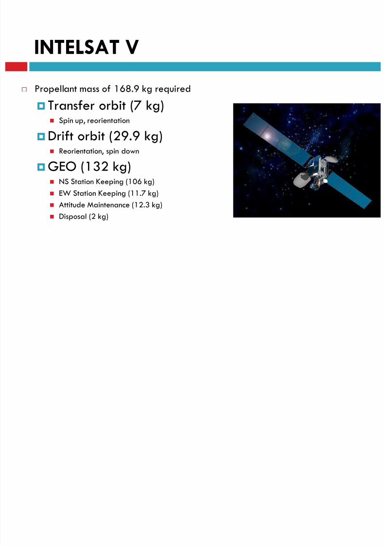
INTELSAT V
8/23/2019 Sdac Lec 9 10 Space Propulsion
http://slidepdf.com/reader/full/sdac-lec-9-10-space-propulsion 190/239
Propellant mass of 168.9 kg required
Transfer orbit (7 kg) Spin up, reorientation
Drift orbit (29.9 kg) Reorientation, spin down
GEO (132 kg) NS Station Keeping (106 kg)
EW Station Keeping (11.7 kg)
Attitude Maintenance (12.3 kg)
Disposal (2 kg)
INTELSAT V
8/23/2019 Sdac Lec 9 10 Space Propulsion
http://slidepdf.com/reader/full/sdac-lec-9-10-space-propulsion 191/239
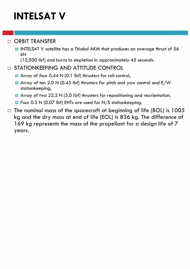
ORBIT TRANSFER INTELSAT V satellite has a Thiokol AKM that produces an average thrust of 56
kN(12,500 lbf) and burns to depletion in approximately 45 seconds.
STATIONKEEPING AND ATTITUDE CONTROL
Array of four 0.44 N (0.1 lbf) thrusters for roll control,
Array of ten 2.0 N (0.45 lbf) thrusters for pitch and yaw control and E/Wstationkeeping,
Array of two 22.2 N (5.0 lbf) thrusters for repositioning and reorientation.
Four 0.3 N (0.07 lbf) EHTs are used for N/S stationkeeping.
The nominal mass of the spacecraft at beginning of life (BOL) is 1005kg and the dry mass at end of life (EOL) is 836 kg. The difference of169 kg represents the mass of the propellant for a design life of 7years.
8/23/2019 Sdac Lec 9 10 Space Propulsion
http://slidepdf.com/reader/full/sdac-lec-9-10-space-propulsion 192/239
LECTURE # 9
SPACECRAFT PROPULSIONCHEMICAL PROPULSION
Chemical Propulsion
8/23/2019 Sdac Lec 9 10 Space Propulsion
http://slidepdf.com/reader/full/sdac-lec-9-10-space-propulsion 193/239
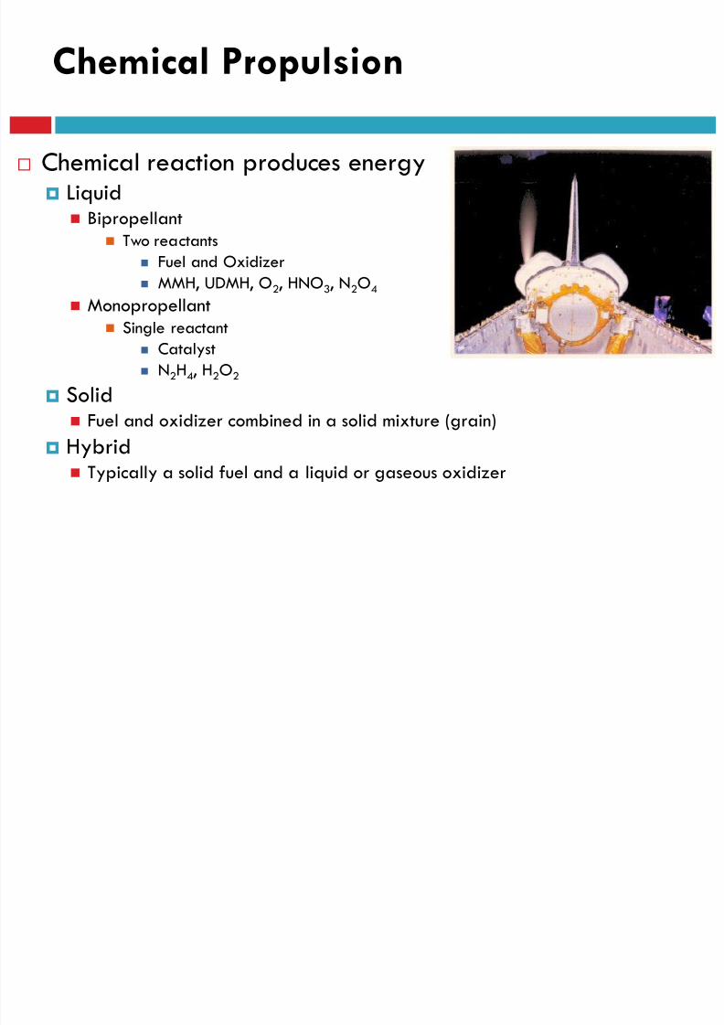
Chemical reaction produces energy Liquid
Bipropellant Two reactants
Fuel and Oxidizer
MMH, UDMH, O2, HNO3, N2O4
Monopropellant Single reactant
Catalyst
N2H4, H2O2
Solid Fuel and oxidizer combined in a solid mixture (grain)
Hybrid Typically a solid fuel and a liquid or gaseous oxidizer

8/23/2019 Sdac Lec 9 10 Space Propulsion
http://slidepdf.com/reader/full/sdac-lec-9-10-space-propulsion 194/239
LECTURE # 9
SPACECRAFT PROPULSIONSOLAR ELECTRIC PROPULSION
Solar Electric Propulsion
8/23/2019 Sdac Lec 9 10 Space Propulsion
http://slidepdf.com/reader/full/sdac-lec-9-10-space-propulsion 195/239
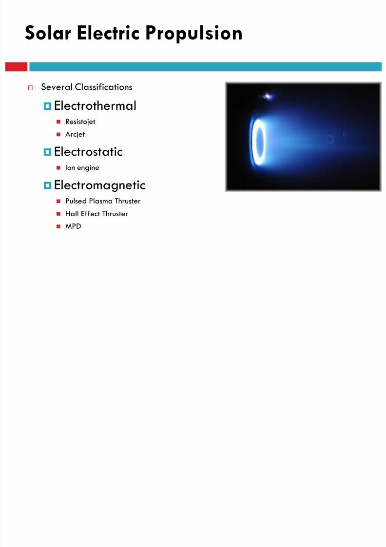
Several Classifications
Electrothermal Resistojet
Arcjet
Electrostatic Ion engine
Electromagnetic Pulsed Plasma Thruster
Hall Effect Thruster MPD

8/23/2019 Sdac Lec 9 10 Space Propulsion
http://slidepdf.com/reader/full/sdac-lec-9-10-space-propulsion 196/239
LECTURE # 9
SPACECRAFT PROPULSIONNUCLEAR PROPULSION
Nuclear Propulsion
8/23/2019 Sdac Lec 9 10 Space Propulsion
http://slidepdf.com/reader/full/sdac-lec-9-10-space-propulsion 197/239
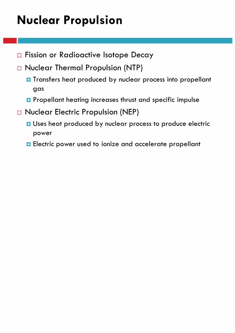
Fission or Radioactive Isotope Decay
Nuclear Thermal Propulsion (NTP)
Transfers heat produced by nuclear process into propellant
gas Propellant heating increases thrust and specific impulse
Nuclear Electric Propulsion (NEP)
Uses heat produced by nuclear process to produce electric
power
Electric power used to ionize and accelerate propellant
8/23/2019 Sdac Lec 9 10 Space Propulsion
http://slidepdf.com/reader/full/sdac-lec-9-10-space-propulsion 198/239
LECTURE # 9
SPACECRAFT PROPULSIONPROPELLANT LESS PROPULSION
Propellant-less Propulsion

8/23/2019 Sdac Lec 9 10 Space Propulsion
http://slidepdf.com/reader/full/sdac-lec-9-10-space-propulsion 199/239
Solar Sail
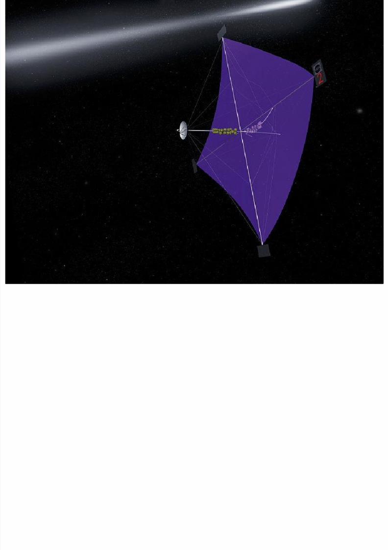
Uses solar pressure to generate thrust
Large, reflective surface area required
Electrodynamic TetherUses Earth’s (or other planet’s) magnetic field to
generate a force (with an electric current) Atmospheric Drag
AerobrakingRe-entry
8/23/2019 Sdac Lec 9 10 Space Propulsion
http://slidepdf.com/reader/full/sdac-lec-9-10-space-propulsion 200/239
LECTURE # 9
SOLAR SAILS
SOLAR SAILS

8/23/2019 Sdac Lec 9 10 Space Propulsion
http://slidepdf.com/reader/full/sdac-lec-9-10-space-propulsion 201/239
Small solar sails, (devices that produce thrust as a reaction force induced by
reflecting incident light) may be used to make small attitude control and
velocity adjustments.
This application can save large amounts of fuel on a long-duration missionby producing control moments without fuel expenditure.
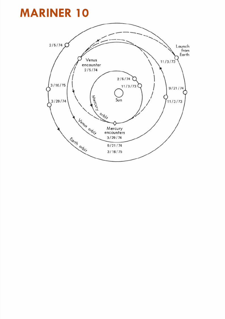
For example, Mariner 10 adjusted its attitude using its solar cells andantennas as small solar sails
SOLAR SAILS
8/23/2019 Sdac Lec 9 10 Space Propulsion
http://slidepdf.com/reader/full/sdac-lec-9-10-space-propulsion 202/239
Small solar sails, (devices that produce thrust as a reaction force induced by
reflecting incident light) may be used to make small attitude control and
velocity adjustments.
This application can save large amounts of fuel on a long-duration missionby producing control moments without fuel expenditure.
For example, Mariner 10 adjusted its attitude using its solar cells andantennas as small solar sails
SOLAR SAILS

8/23/2019 Sdac Lec 9 10 Space Propulsion
http://slidepdf.com/reader/full/sdac-lec-9-10-space-propulsion 203/239
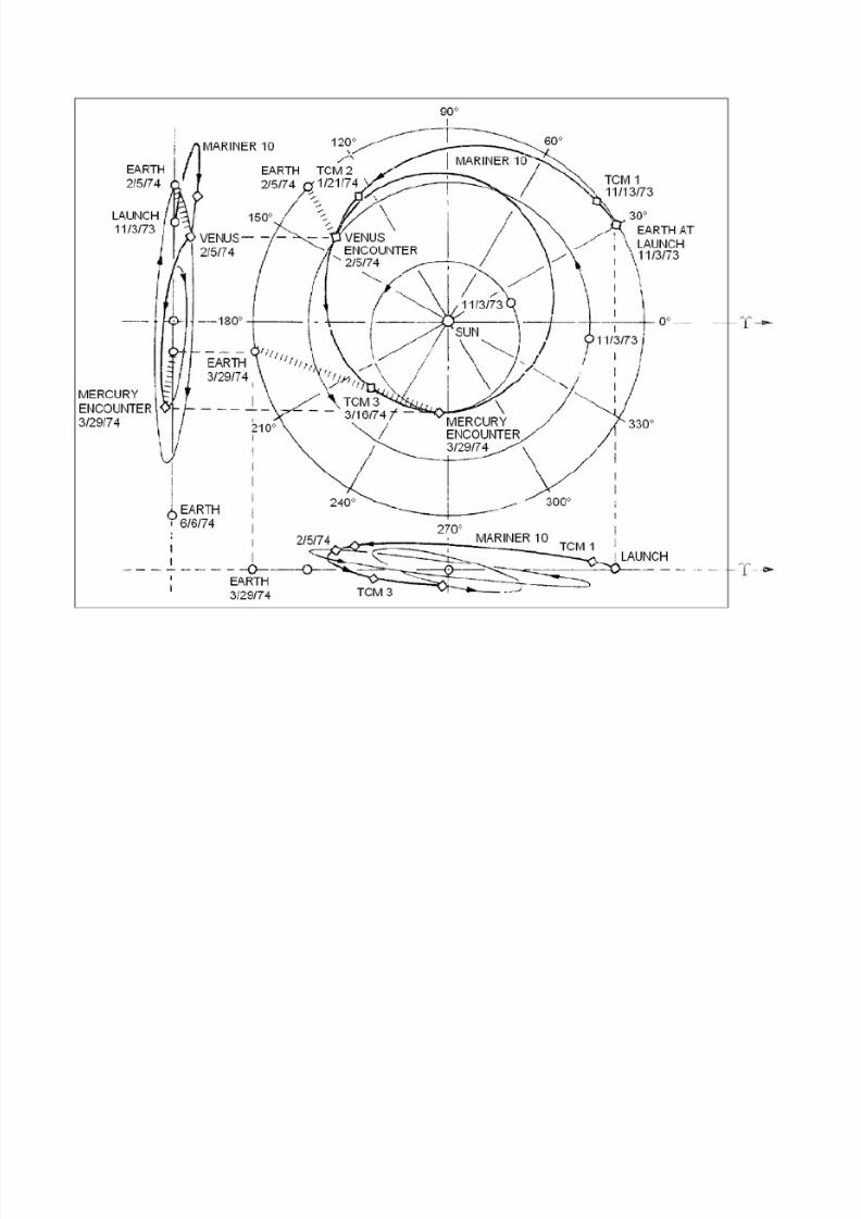
Mariner 10 was an American robotic space
probe launched by NASA on November 3,
1973, to fly by the planets Mercury and Venus.
Mariner 10 was launched approximately two
years after Mariner 9 and was the last
spacecraft in the Mariner program (Mariner 11
and 12 were allocated to the Voyager
program and redesignated Voyager 1 and
Voyager 2).
The mission objectives were to measure
Mercury's environment, atmosphere, surface,
and body characteristics and to make similar
investigations of Venus. Secondary objectives
were to perform experiments in the
interplanetary medium and to obtain
experience with a dual-planet gravity assist
mission.
There currently is a spacecraft mission doing a
more in-depth survey of Mercury, MESSENGER.
The planning of the mission was dependent on
Mariner 10's data sets.
http://nssdc.gsfc.nasa.gov/nmc/spacecraft
Display.do?id=1973-085A
http://history.nasa.gov/SP-423/mariner.htm
MARINER 10
8/23/2019 Sdac Lec 9 10 Space Propulsion
http://slidepdf.com/reader/full/sdac-lec-9-10-space-propulsion 204/239
8/23/2019 Sdac Lec 9 10 Space Propulsion
http://slidepdf.com/reader/full/sdac-lec-9-10-space-propulsion 205/239

8/23/2019 Sdac Lec 9 10 Space Propulsion
http://slidepdf.com/reader/full/sdac-lec-9-10-space-propulsion 206/239
8/23/2019 Sdac Lec 9 10 Space Propulsion
http://slidepdf.com/reader/full/sdac-lec-9-10-space-propulsion 207/239
MARINER 10
8/23/2019 Sdac Lec 9 10 Space Propulsion
http://slidepdf.com/reader/full/sdac-lec-9-10-space-propulsion 208/239
MARINER 10

8/23/2019 Sdac Lec 9 10 Space Propulsion
http://slidepdf.com/reader/full/sdac-lec-9-10-space-propulsion 209/239
MARINER 10

8/23/2019 Sdac Lec 9 10 Space Propulsion
http://slidepdf.com/reader/full/sdac-lec-9-10-space-propulsion 210/239
MARINER 10
Mariner 10 image showing a scarp on the plains of
Mercury. The SW-NE trending scarp, which may have
been formed by compressional stresses is radial to

8/23/2019 Sdac Lec 9 10 Space Propulsion
http://slidepdf.com/reader/full/sdac-lec-9-10-space-propulsion 211/239
been formed by compressional stresses, is radial to
the Caloris Basin, to the southwest (north is up). Theimage is about 240 km across. (Mariner 10, Atlas of
Mercury,
Location & Time Information
Date/Time (UT): 1974-03-30
Distance/Range (km): N/A
Central Latitude/Longitude (deg): +52.50/171.00
Orbit(s): Flyby
Imaging Information
Area or Feature Type: scarp, crater, plains
Instrument: GEC 1-inch vidicon tube (TV) camera
Instrument Resolution (pixels): 700 x 832, 8 bit
Instrument Field of View (deg): 0.38 x 0.47
Filter: N/A
Illumination Incidence Angle (deg): N/A
Phase Angle (deg): N/A
Instrument Look Direction: N/ASurface Emission Angle (deg): N/A
MARINER 10
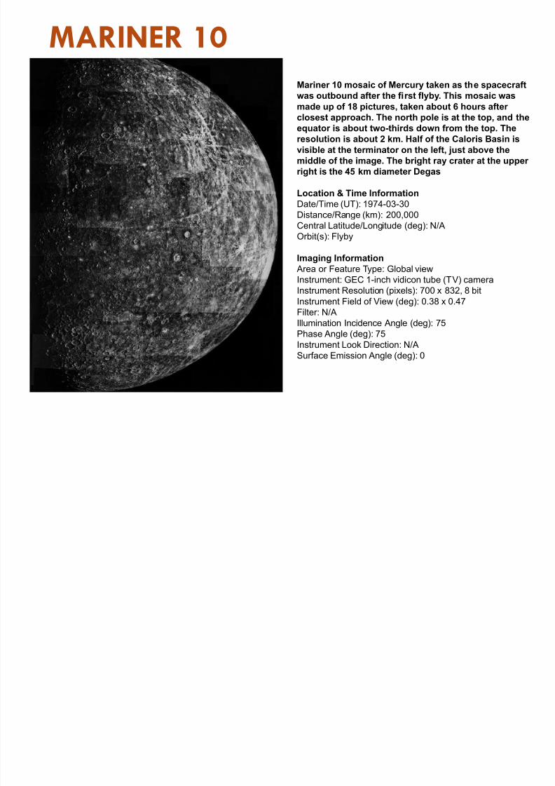
Mariner 10 mosaic of Mercury taken as the spacecraft
was outbound after the first flyby. This mosaic was
made up of 18 pictures taken about 6 hours after
8/23/2019 Sdac Lec 9 10 Space Propulsion
http://slidepdf.com/reader/full/sdac-lec-9-10-space-propulsion 212/239
made up of 18 pictures, taken about 6 hours after
closest approach. The north pole is at the top, and theequator is about two-thirds down from the top. The
resolution is about 2 km. Half of the Caloris Basin is
visible at the terminator on the left, just above the
middle of the image. The bright ray crater at the upper
right is the 45 km diameter Degas
Location & Time Information
Date/Time (UT): 1974-03-30
Distance/Range (km): 200,000Central Latitude/Longitude (deg): N/A
Orbit(s): Flyby
Imaging Information
Area or Feature Type: Global view
Instrument: GEC 1-inch vidicon tube (TV) camera
Instrument Resolution (pixels): 700 x 832, 8 bit
Instrument Field of View (deg): 0.38 x 0.47
Filter: N/AIllumination Incidence Angle (deg): 75
Phase Angle (deg): 75
Instrument Look Direction: N/A
Surface Emission Angle (deg): 0
SOLAR SAILS
8/23/2019 Sdac Lec 9 10 Space Propulsion
http://slidepdf.com/reader/full/sdac-lec-9-10-space-propulsion 213/239
Solar sails (also called light sails or photon sails)are a form of spacecraft propulsion using theradiation pressure (also called solar pressure) ofa combination of light and high speed ejectedgasses from a star to push large ultra-thin
mirrors to high speeds. Light sails could also be driven by energy beams
to extend their range of operations, which isstrictly beam sailing rather than solar sailing.
Solar sail craft offer the possibility of low-costoperations combined with long operatinglifetimes.
Since they have few moving parts and use nopropellant, they can potentially be usednumerous times for delivery of payloads.
8/23/2019 Sdac Lec 9 10 Space Propulsion
http://slidepdf.com/reader/full/sdac-lec-9-10-space-propulsion 214/239
8/23/2019 Sdac Lec 9 10 Space Propulsion
http://slidepdf.com/reader/full/sdac-lec-9-10-space-propulsion 215/239
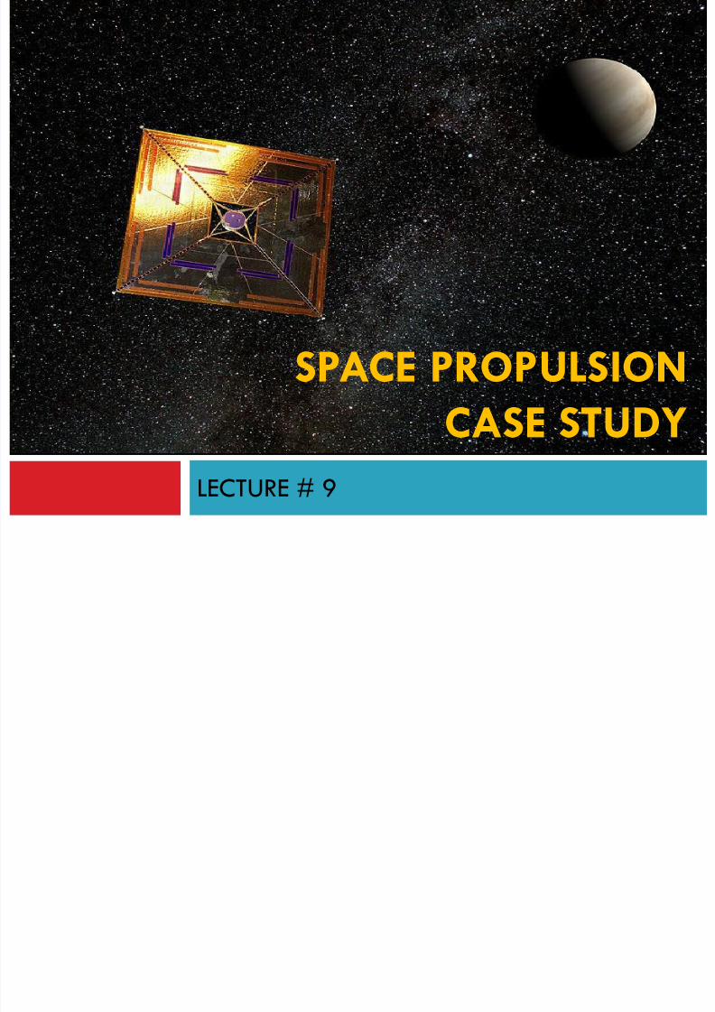
LECTURE # 9
SPACE PROPULSION
CASE STUDY
SPACE PROPULSION – CASE STUDY
8/23/2019 Sdac Lec 9 10 Space Propulsion
http://slidepdf.com/reader/full/sdac-lec-9-10-space-propulsion 216/239
Summarizes key features and performance characteristics of existing andplanned (near future) propulsion systems for use on spacecraft such as
satellites
This study demonstrates the design of a baseline orbital propulsion systemfor a spacecraft with a total loaded mass of 5000 kg (including the
propulsion subsystem). In more detail, the propulsion system should allow
for the spacecraft to perform a coplanar LEO-GEO orbit transfer mission.
Three options are considered:
1. Minimum energy, high thrust (Impulsive shot)
2. Low thrust chemical
3. Low thrust (spiral transfer)
SPACE PROPULSION – CASE STUDY
8/23/2019 Sdac Lec 9 10 Space Propulsion
http://slidepdf.com/reader/full/sdac-lec-9-10-space-propulsion 217/239
The main difference is in the velocity change required, the thrust level and themission duration.
We determine subsequently the various propulsion options for use, their main
advantages and disadvantages with respect to amongst others functionality,operation and cost, and calculate propulsion subsystem and net vehicle mass
(vehicle mass excluding propulsion system).
The results are compared and the various systems assessed for their missionsuitability.
No attempts are made to determine the effects of varying total vehicle mass
on the outcome of this assessment. Also we neglect the need for a margin on required velocity change to account
for mission uncertainties.
SPACE PROPULSION – CASE STUDY

8/23/2019 Sdac Lec 9 10 Space Propulsion
http://slidepdf.com/reader/full/sdac-lec-9-10-space-propulsion 218/239
Propulsion Options
The following propulsion options are considered as candidate for the mission at
hand:
Chemical:
a. Liquid bipropellant i. Cryogenic
ii. Storable
b. Solid
c. Hybrid
Other propulsion options like chemical monopropellant, laser-thermal, nuclear-
thermal, plasma, and tethered propulsion are left out of consideration to limit
the amount of analysis to be performed.
SPACE PROPULSION – CASE STUDY
8/23/2019 Sdac Lec 9 10 Space Propulsion
http://slidepdf.com/reader/full/sdac-lec-9-10-space-propulsion 219/239
System Concept Analysis and Design
Many missions desire minimal mass to reduce the mission cost, which may be
achieved in part by choosing the appropriate propulsion system.
Some military missions and manned missions, however, may prefer minimal TOF over
minimal cost associated with minimal mass.
At times, the choices for the orbit transfer and propulsion system may be obvious,
but, the appropriate design is not obvious, given that designing a propulsion system
depends on the transfer orbit chosen, and vice versa.
For such design problem, a tool that designs the orbit transfer and propulsion
system may alleviate the difficulty in solving the coupled problem
SPACE PROPULSION – CASE STUDY

8/23/2019 Sdac Lec 9 10 Space Propulsion
http://slidepdf.com/reader/full/sdac-lec-9-10-space-propulsion 220/239
System Concept Analysis and Design
We could go through a detailed analysis to determine the mass of propulsion
system, but, it becomes very complex and tedious.
There are many detailed design choices required to compute the propulsion system
mass, we take a very simple approach to approximating the propulsion system
mass.
To develop a propulsion budget based on a given V budget, for PreliminaryDesign, we can estimate the cost of the space mission by using the rocket equation
to determine the total required spacecraft plus propellant mass, in terms of the dry
mass of the spacecraft, the total required V
)ln(lnln R gI m
m gI
mm
m gI V sp
f
o sp
po
o sp
1
)/(
g I V
f p spemm
SPACE PROPULSION – CASE STUDY
8/23/2019 Sdac Lec 9 10 Space Propulsion
http://slidepdf.com/reader/full/sdac-lec-9-10-space-propulsion 221/239
System Concept Analysis and Design
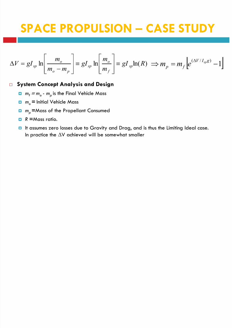
mf mo - mp is the Final Vehicle Mass
mo = Initial Vehicle Mass
mp =Mass of the Propellant Consumed
R =Mass ratio.
It assumes zero losses due to Gravity and Drag, and is thus the Limiting Ideal case.In practice the V achieved will be somewhat smaller
)ln(lnln R gI m
m gI
mm
m gI V sp
f
o sp
po
o sp
1
)/(
g I V
f p spemm
SPACE PROPULSION – CASE STUDY

8/23/2019 Sdac Lec 9 10 Space Propulsion
http://slidepdf.com/reader/full/sdac-lec-9-10-space-propulsion 222/239
System Concept Analysis and Design
Isp is the most important and first figure of merit.
Note that the Isp is dependant on the nature of propellant, nozzle design, ambient
pressure, and combustion efficiency.
Given a structural mass fraction rs for the propulsion system, the total mass of the
propulsion system is
)ln(lnln R gI m
m gI
mm
m gI V sp
f
o sp
po
o sp
1
)/(
g I V
f p spemm
s
p
total r
mm
1
SPACE PROPULSION – CASE STUDY
8/23/2019 Sdac Lec 9 10 Space Propulsion
http://slidepdf.com/reader/full/sdac-lec-9-10-space-propulsion 223/239
System Concept Analysis and Design
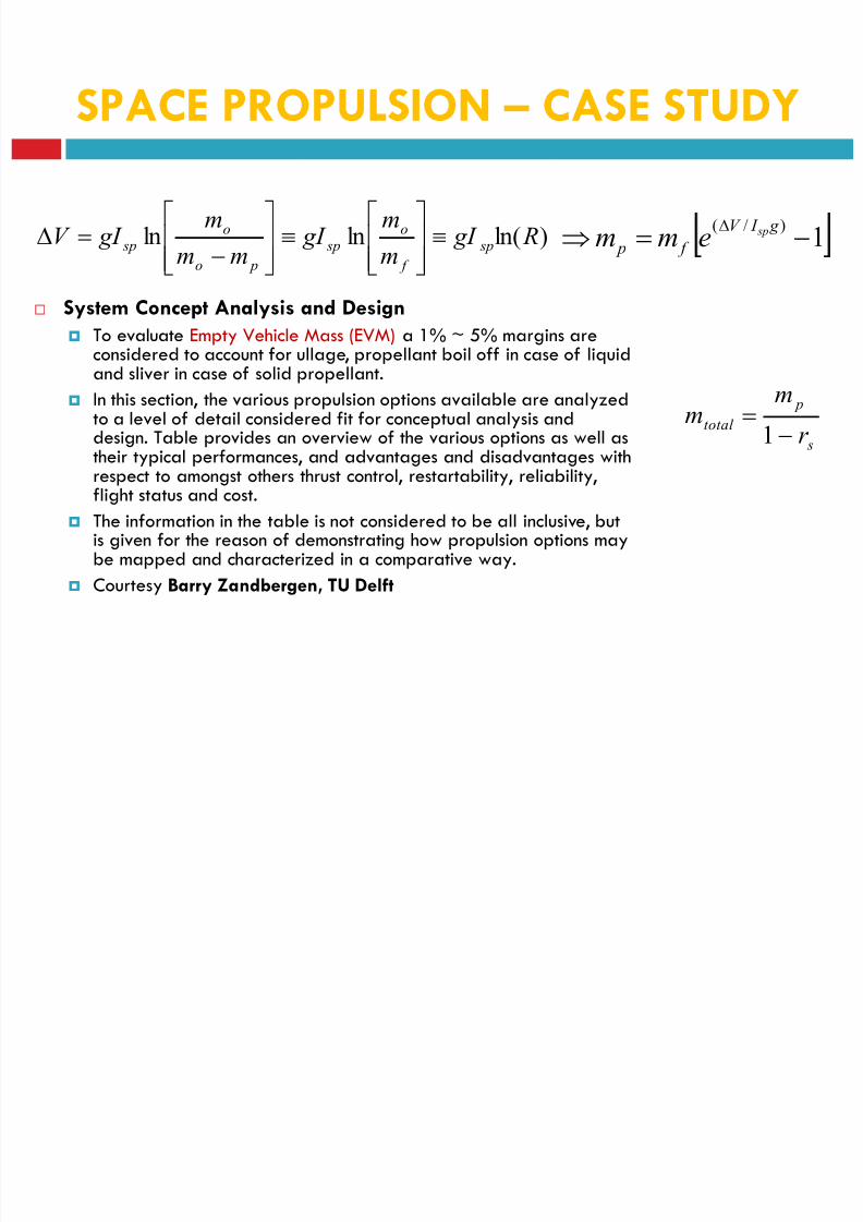
To evaluate Empty Vehicle Mass (EVM) a 1% ~ 5% margins areconsidered to account for ullage, propellant boil off in case of liquidand sliver in case of solid propellant.
In this section, the various propulsion options available are analyzedto a level of detail considered fit for conceptual analysis anddesign. Table provides an overview of the various options as well astheir typical performances, and advantages and disadvantages with
respect to amongst others thrust control, restartability, reliability,flight status and cost.
The information in the table is not considered to be all inclusive, butis given for the reason of demonstrating how propulsion options maybe mapped and characterized in a comparative way.
Courtesy Barry Zandbergen, TU Delft
)ln(lnln R gI m
m gI
mm
m gI V sp
f
o sp
po
o sp
1
)/(
g I V
f p spemm
s
p
total r
mm
1
SPACE PROPULSION – CASE STUDY
8/23/2019 Sdac Lec 9 10 Space Propulsion
http://slidepdf.com/reader/full/sdac-lec-9-10-space-propulsion 224/239
System Concept Analysis and Design
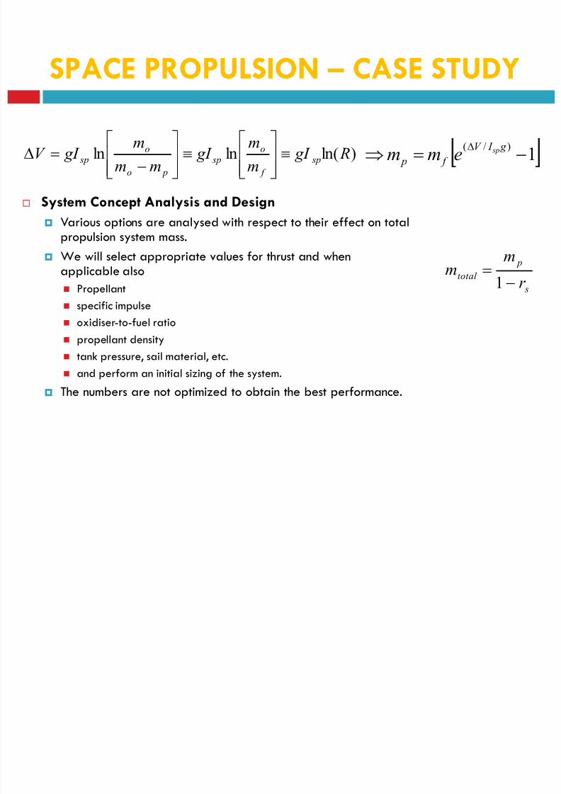
Various options are analysed with respect to their effect on totalpropulsion system mass.
We will select appropriate values for thrust and whenapplicable also
Propellant
specific impulse
oxidiser-to-fuel ratio
propellant density
tank pressure, sail material, etc.
and perform an initial sizing of the system.
The numbers are not optimized to obtain the best performance.
)ln(lnln R gI m
m gI
mm
m gI V sp
f
o sp
po
o sp
1
)/(
g I V
f p spemm
s
p
total r
mm
1
SPACE PROPULSION – CASE STUDY
No System ConceptTypical (vacuum)
performances
Advantage/
DisadvantageRemark
1
Cryogenic
chemical
bipropellant
Propellant: Liquid hydrogen &
liquid oxygen Isp: 400-450 sec
Typical oxidiser/fuel mass ratio
is 5. Thrust level: High (~kN)
Advantages: • Space qualified • Used today mostly for
launcher stages including some upper stages • Extensive in
flight heritage • Highest average Isp with respect to other pure
chemical systems Disadvantages: • Expensive and complex
compared to other chemical systems due to low temperature
storage of propellants (hydrogen at 20 K and oxygen at 80 K) •
high g-load on s/c due to relatively high thrust (necessary to
reduce storage time)
Presently only used for
short duration launcher
missions (Ariane 5, Space
Shuttle, Centaur)
P ll t MMH/h d iAdvantages: • Space qualified • Extensive in flight heritage •
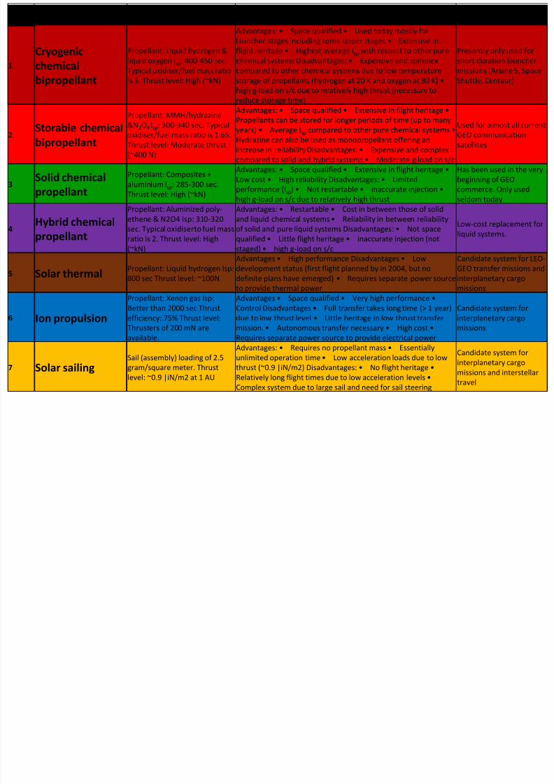
8/23/2019 Sdac Lec 9 10 Space Propulsion
http://slidepdf.com/reader/full/sdac-lec-9-10-space-propulsion 225/239
2Storable chemical
bipropellant
Propellant: MMH/hydrazine
&N2O4 Isp: 300-340 sec. Typical
oxidiser/fuel mass ratio is 1.65.
Thrust level: Moderate thrust
(~400 N)
g p q g g
Propellants can be stored for longer periods of time (up to manyyears) • Average Isp compared to other pure chemical systems •
Hydrazine can also be used as monopropellant offering an
increase in reliability Disadvantages: • Expensive and complex
compared to solid and hybrid systems • Moderate g-load on s/c
Used for almost all current
GEO communication
satellites
3Solid chemical
propellant
Propellant: Composites +
aluminium Isp: 285-300 sec.
Thrust level: High (~kN)
Advantages: • Space qualified • Extensive in flight heritage •
Low cost • High reliability Disadvantages: • Limited
performance (Isp) • Not restartable • inaccurate injection •
high g-load on s/c due to relatively high thrust
Has been used in the very
beginning of GEO
commerce. Only used
seldom today
4Hybrid chemical
propellant
Propellant: Aluminized poly-
ethene & N2O4 Isp: 310-320
sec. Typical oxidiserto fuel mass
ratio is 2. Thrust level: High
(~kN)
Advantages: • Restartable • Cost in between those of solid
and liquid chemical systems • Reliability in between reliability
of solid and pure liquid systems Disadvantages: • Not space
qualified • Little flight heritage • inaccurate injection (not
staged) • high g-load on s/c
Low-cost replacement for
liquid systems.
5 Solar thermalPropellant: Liquid hydrogen Isp:
800 sec Thrust level: ~100N
Advantages • High performance Disadvantages • Low
development status (first flight planned by in 2004, but no
definite plans have emerged) • Requires separate power source
to provide thermal power
Candidate system for LEO-
GEO transfer missions and
interplanetary cargo
missions
6 Ion propulsion
Propellant: Xenon gas Isp:
Better than 2000 sec Thrustefficiency: 75% Thrust level:
Thrusters of 200 mN are
available.
Advantages • Space qualified • Very high performance •
Control Disadvantages • Full transfer takes long time (> 1 year)due to low thrust level • Little heritage in low thrust transfer
mission. • Autonomous transfer necessary • High cost •
Requires separate power source to provide electrical power
Candidate system forinterplanetary cargo
missions
7 Solar sailingSail (assembly) loading of 2.5
gram/square meter. Thrust
level: ~0.9 |iN/m2 at 1 AU
Advantages: • Requires no propellant mass • Essentially
unlimited operation time • Low acceleration loads due to low
thrust (~0.9 |iN/m2) Disadvantages: • No flight heritage •
Relatively long flight times due to low acceleration levels •
Complex system due to large sail and need for sail steering
Candidate system for
interplanetary cargo
missions and interstellar
travel
PropertyLiquid
Cryogenic
Liquid
Storable
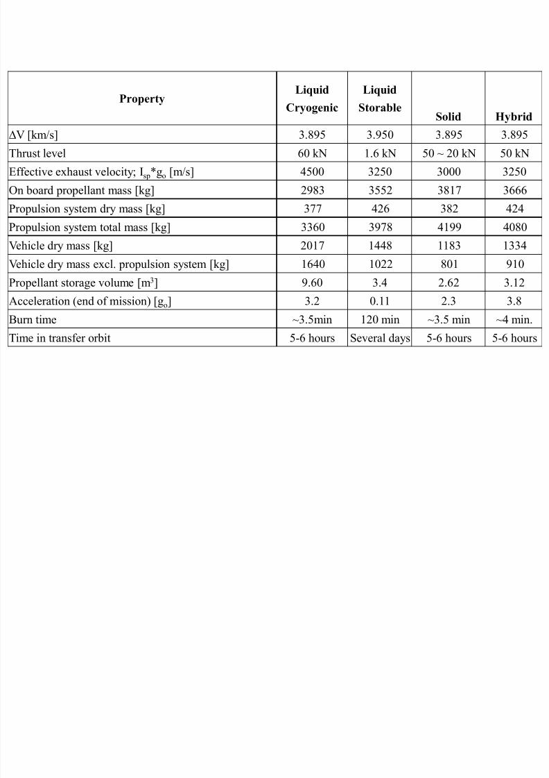
8/23/2019 Sdac Lec 9 10 Space Propulsion
http://slidepdf.com/reader/full/sdac-lec-9-10-space-propulsion 226/239
y g
Solid HybridV [km/s] 3.895 3.950 3.895 3.895
Thrust level 60 kN 1.6 kN 50 ~ 20 kN 50 kN
Effective exhaust velocity; Isp*go [m/s] 4500 3250 3000 3250
On board propellant mass [kg] 2983 3552 3817 3666
Propulsion system dry mass [kg] 377 426 382 424Propulsion system total mass [kg] 3360 3978 4199 4080
Vehicle dry mass [kg] 2017 1448 1183 1334
Vehicle dry mass excl. propulsion system [kg] 1640 1022 801 910
Propellant storage volume [m3] 9.60 3.4 2.62 3.12
Acceleration (end of mission) [go
] 3.2 0.11 2.3 3.8
Burn time ~3.5min 120 min ~3.5 min ~4 min.
Time in transfer orbit 5-6 hours Several days 5-6 hours 5-6 hours
Property
Liquid
Cryogeni
c
Liquid
StorableSolid Hybrid
Solar
Thermal
Ion
Prop
Solar
Sail
V [km/s] 3.895 3.950 3.895 3.895 4.611 4710 4710
Thrust level 60 kN 1.6 kN 50 ~ 20 kN 50 kN 100 N 1.4 N 0.56

8/23/2019 Sdac Lec 9 10 Space Propulsion
http://slidepdf.com/reader/full/sdac-lec-9-10-space-propulsion 227/239
Effective exhaust velocity; Isp*go [m/s] 4500 3250 3000 3250 8000 20000 -
On board propellant mass [kg] 2983 3552 3817 3666 2300 1060 -
Propulsion system dry mass [kg] 377 426 382 424 2180 2181 -
Propulsion system total mass [kg] 3360 3978 4199 4080 4480 3241 2500
Vehicle dry mass [kg] 2017 1448 1183 1334 2700 3940 5000
Vehicle dry mass excl. propulsion system
[kg]1640 1022 801 910 520 1759 2500
Propellant storage volume [m3] 9.60 3.4 2.62 3.12 33.3 1.96 -
Collector/solar array/sail area [m2] - - - - 396.8 95.2 1x10⁶
Acceleration (end of mission) [go] 3.2 0.11 2.3 3.8 0.002 0.00003 0.000016
Burn time ~3.5min 120 min ~3.5 min ~4 min. ~45 hour ~173 days ~1 year
Time in transfer orbit 5-6 hoursSeveral
days5-6 hours
5-6
hours
Multiple
days
~173 days
(~1/2 year)~2 year
Characteristics PAM-D PAM-DII TOS IUS Centaur H-10 D-M L-9
Stage: Manufacturer
Boeing Boeing Lockheed Martin Boeing
Lockheed
Martin Ariane-space RSC Energia Ariane-spaceLength (m) 2.04 2.00 3.30 5.20 9.0 9.9 6.8 4.5
Diameter (m) 1.25 1.62 3.44 2.90 4.3 2.6 4.1 5.4
Engine: ManufacturerThiokol Thiokol CSD CSD
Pratt-
WhitneySNECMA Isayev DASA
Type (Star 48) ISTP SRM-1 SRM-1, SRM-2 RL 10A-3-3A HM7B 11 DM 58 Aestus
Number 1 1 1 1, 1 2 1 1 1
Fuel Solid Solid Solid Solid LO2LH2 LO2LH2 LOX RP1 N2O4/ MMH
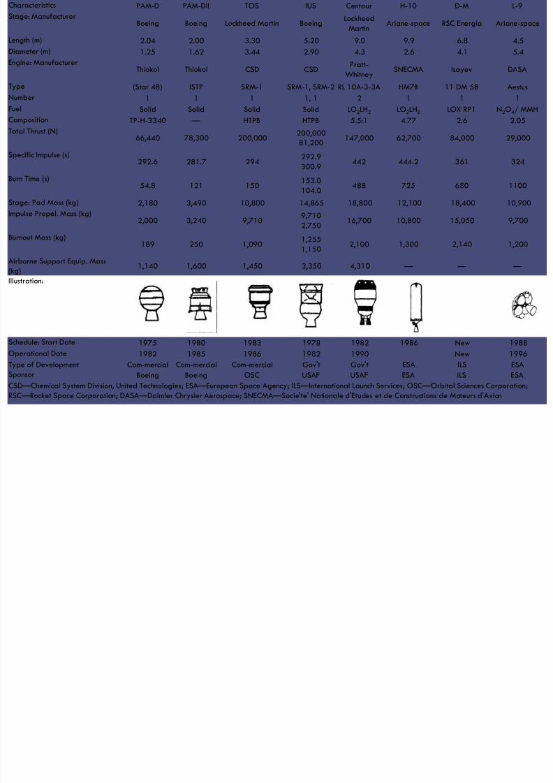
8/23/2019 Sdac Lec 9 10 Space Propulsion
http://slidepdf.com/reader/full/sdac-lec-9-10-space-propulsion 228/239
Composition TP-H-3340 — HTPB HTPB 5.5:1 4.77 2.6 2.05Total Thrust (N)
66,440 78,300 200,000200,00081,200
147,000 62,700 84,000 29,000
Specific Impulse (s)292.6 281.7 294
292.9
300.9442 444.2 361 324
Burn Time (s)54.8 121 150
153.0
104.0488 725 680 1100
Stage: Pad Mass (kg) 2,180 3,490 10,800 14,865 18,800 12,100 18,400 10,900
Impulse Propel. Mass (kg) 2,000 3,240 9,710 9,7102,750
16,700 10,800 15,050 9,700
Burnout Mass (kg)189 250 1,090
1,255
1,1502,100 1,300 2,140 1,200
Airborne Support Equip. Mass
(kg)1,140 1,600 1,450 3,350 4,310 — — —
Illustration:
Schedule: Start Date 1975 1980 1983 1978 1982 1986 New 1988
Operational Date 1982 1985 1986 1982 1990 New 1996
Type of Development Commercial Commercial Commercial Gov't Gov't ESA ILS ESASponsor Boeing Boeing OSC USAF USAF ESA ILS ESA
CSD — Chemical System Division, United Technologies; ESA — European Space Agency; ILS — International Launch Services; OSC — Orbital Sciences Corporation;
RSC — Rocket Space Corporation; DASA — Daimler Chrysler Aerospace; SNECMA — Socie'te' Nationale d'Etudes et de Constructions de Moteurs d'Avion

8/23/2019 Sdac Lec 9 10 Space Propulsion
http://slidepdf.com/reader/full/sdac-lec-9-10-space-propulsion 229/239
LECTURE # 9
SPACE PROPULSION
COMPARISON
COMPARISON

8/23/2019 Sdac Lec 9 10 Space Propulsion
http://slidepdf.com/reader/full/sdac-lec-9-10-space-propulsion 230/239
COMPARISON
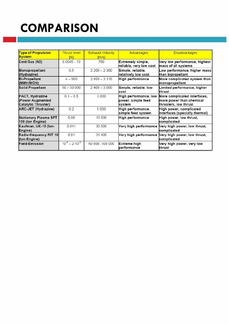
8/23/2019 Sdac Lec 9 10 Space Propulsion
http://slidepdf.com/reader/full/sdac-lec-9-10-space-propulsion 231/239
COMPARISON

8/23/2019 Sdac Lec 9 10 Space Propulsion
http://slidepdf.com/reader/full/sdac-lec-9-10-space-propulsion 232/239
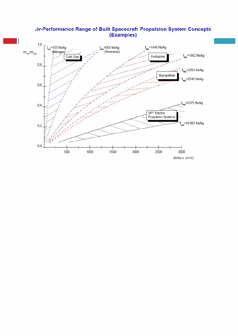
8/23/2019 Sdac Lec 9 10 Space Propulsion
http://slidepdf.com/reader/full/sdac-lec-9-10-space-propulsion 233/239
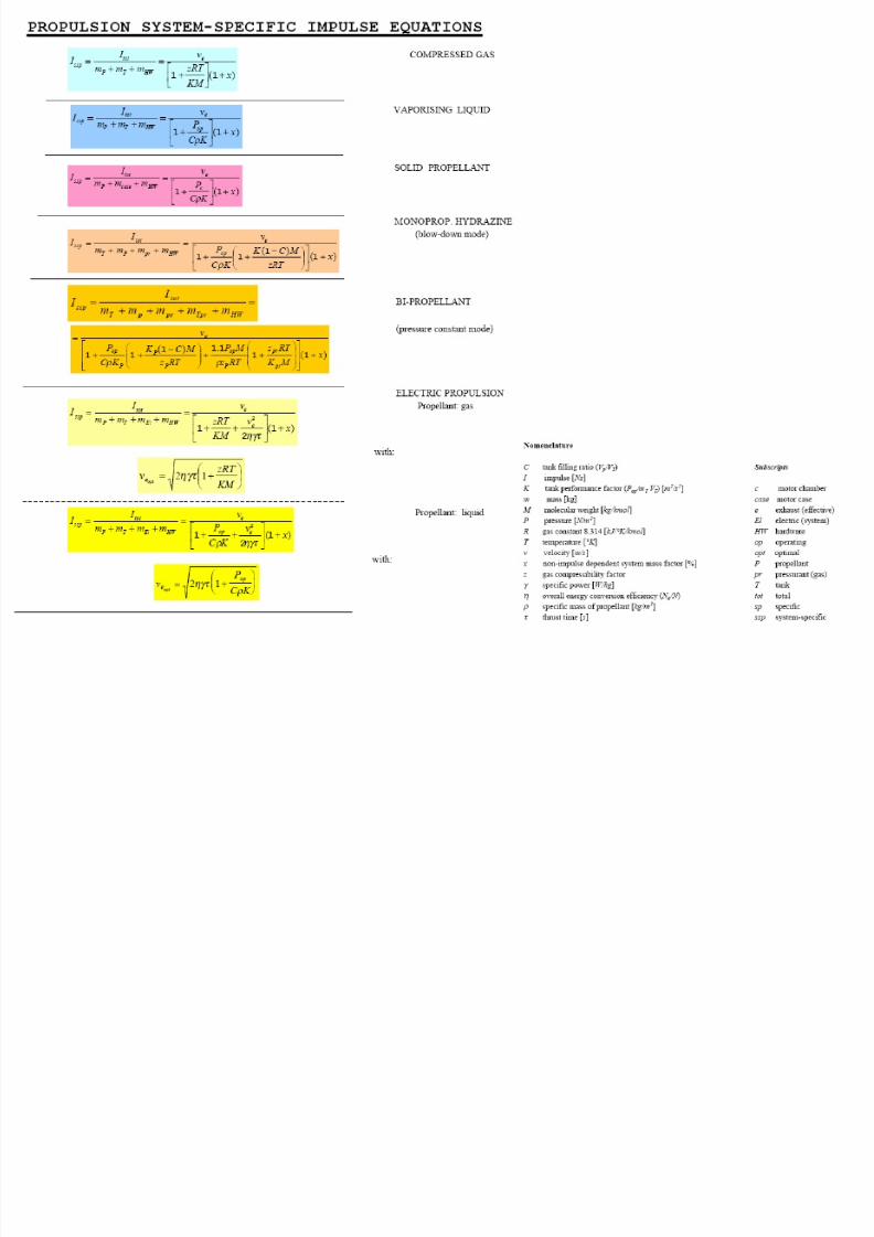
8/23/2019 Sdac Lec 9 10 Space Propulsion
http://slidepdf.com/reader/full/sdac-lec-9-10-space-propulsion 234/239
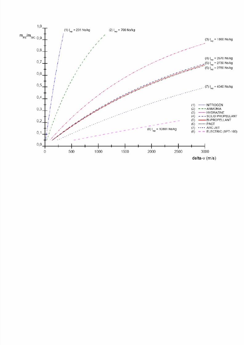
8/23/2019 Sdac Lec 9 10 Space Propulsion
http://slidepdf.com/reader/full/sdac-lec-9-10-space-propulsion 235/239

8/23/2019 Sdac Lec 9 10 Space Propulsion
http://slidepdf.com/reader/full/sdac-lec-9-10-space-propulsion 236/239
COMPARISON
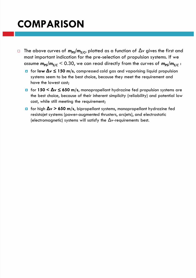
8/23/2019 Sdac Lec 9 10 Space Propulsion
http://slidepdf.com/reader/full/sdac-lec-9-10-space-propulsion 237/239
The above curves of m PS /m S/C, plotted as a function of Δv gives the first and
most important indication for the pre-selection of propulsion systems. If we
assume m PS /m S/C < 0.30, we can read directly from the curves of m PS /m S/C :
for low Δv ≤ 150 m/s, compressed cold gas and vaporising liquid propulsion
systems seem to be the best choice, because they meet the requirement andhave the lowest cost;
for 150 < Δv ≤ 650 m/s, monopropellant hydrazine fed propulsion systems are
the best choice, because of their inherent simplicity (reliability) and potential low
cost, while still meeting the requirement;
for high Δv > 650 m/s, bipropellant systems, monopropellant hydrazine fedresistojet systems (power-augmented thrusters, arcjets), and electrostatic
(electromagnetic) systems will satisfy the Δv-requirements best.
8/23/2019 Sdac Lec 9 10 Space Propulsion
http://slidepdf.com/reader/full/sdac-lec-9-10-space-propulsion 238/239
LECTURE # 9
SPACE PROPULSION
FUTURE REQUIREMENTS

8/23/2019 Sdac Lec 9 10 Space Propulsion
http://slidepdf.com/reader/full/sdac-lec-9-10-space-propulsion 239/239
THANK YOU FOR YOUR INTEREST