SD Lauscher - Modeling Community Blog
8
High-quality interface specifications with SysML modelling www.eurailpress.de/sd 3/2011 Sonderdruck aus
Transcript of SD Lauscher - Modeling Community Blog

High-quality interface specifications with SysML modelling
www.eurailpress.de/sd
3/2011
Sonderdruck aus
SD_Lauscher.indd 1SD_Lauscher.indd 1 30.03.11 14:4730.03.11 14:47

SIGNAL + DRAHT (103) 3/2011 10
Interfaces
High-quality interface specifications with SysML modellingThomas Lauscher / Christian Fischer / Thorsten Hiebenthal
This article describes an approach that, starting with a coarse view of the system, leads to a detailed inter-face specification in clearly defined steps. The approach has been devel-oped in the course of many technical discussions in collaboration with rail-way engineering experts of Deutsche Bahn AG. It is especially suitable for creating high-quality specifications in the complex environment of railway engineering. The procedure has be-come standard in the project NeuPro of DB Netz AG. Due to its clear struc-ture, the approach is highly suitable for major projects with large teams of specifiers.
1 Introduction
Railway network operators are increas-
ingly facing the challenge of integrating
subsystems supplied by multiple manu-
facturers. Currently, many interfaces lack
detailed specifications that manufactur-
ers could use for guidance. As a result,
entire systems are normally ordered from
a single supplier.
Within the project NeuPro, DB Netz AG
follows the objective of achieving higher
flexibility by creating standardised inter-
face specifications. Berner & Mattner has
developed an interface specification ap-
proach in support of this goal. The ap-
proach, which is presented in this article,
is based on modelling with SysML (Sys-
tems Modeling Language) [1]. It starts
with a simplified view of the overall sys-
tem and then follows a model-based and
redundancy-free path with clearly de-
fined steps to arrive at the final interface
specification.
2 The challenge
The traditional approach for cooperation
between railway operator and manufac-
turer provides for a clearly defined tran-
sition, which can be described in the V
model according to EN 50126 between
phases 4 and 5 (figure 1) of the RAMS
life cycle (referred to as CENELEC phas-
es below). The blue boxes indicate activ-
ities carried out by the railway operator,
the yellow ones indicate the activities to
be carried out by the manufacturer.
The railway company uses specifica-
tions (CENELEC phase 4) to describe
WHAT the system to be developed
should provide. The manufacturer for
his part develops specifications in sev-
eral steps in CENELEC phases 5 and 6
describing the realization (HOW). Due to
this classical task sharing, the manufac-
turer assumes the responsibility for the
successful operation of the overall sys-
tem comprising the IXL and the field ele-
ments. Consequently, the manufacturer
has to ensure the interoperability of the
subsystems. As a result, the railway op-
erator can only procure the system as a
whole.
In order to achieve higher flexibility
in future, DB Netz AG has resolved to
provide detailed and standardised in-
terface specifications. This means that
DB Netz AG will create interface speci-
fications for those interfaces whose in-
teroperability is to be ensured. This can
only be achieved by taking over tasks
which until now are left for the manufac-
turers to carry out. The right side of fig-
ure 1 shows this constellation, visualised
by blue-yellow boxes.
As the left side of the V model illus-
trates, for example, considerations con-
cerning architecture and distribution
among individual subsystems (CENELEC
phase 5). In some cases, predefinitions
have to be set for CENELEC phase 6,
e. g., regarding specification of electric
currents and voltages. The right side of
the V model reflects additional tasks the
railway operator has to perform. These
are tasks that so far have been tak-
en over by manufacturers in CENELEC
phases 8 and 9.
The interface specification is the most
important document needed to ena-
ble interoperable systems from multi-
ple manufacturers. An interface specifi-
cation has to comprise the following re-
quirements:
Compilation and description of all
functional processes to be covered by
the interface,
compilation of all non-functional re-
quirements to be implemented by the
interface, e.g., RAMS(S) requirements, Figure 1: V model according to EN 50126 with old and new approach
SD_Lauscher.indd 10SD_Lauscher.indd 10 30.03.11 14:4730.03.11 14:47

SIGNAL + DRAHT (103) 3/2011 11
Interfaces
detailing of all data to be transmitted
via the interface,
technical details to be considered to
enable the two subsystems to be con-
nected.
The requirements of these categories
lead to a technical interface specification
for all ISO/OSI layers.
It is the interface specification author’s
duty to provide a binding architecture
and define in detail which tasks each
subsystem covers. Finally, he has to de-
scribe the interfaces between the sub-
systems for all ISO/OSI layers in such
detail that interoperability is ensured.
These are tasks from the CENELEC
phases 5 and 6 that railway operators
have not yet been concerned with in this
way.
A recipe-like approach is desirable to
fulfil the requirements of writing interface
specifications, which is quite a complex
task. Such an approach would guide rail-
way engineering experts through all the
steps necessary to obtain the final inter-
face specification. A procedure of this
kind, currently being developed in the
NeuPro project at DB Netz AG, is de-
scribed below.
3 The solution path
The solution path is divided into two
phases: modelling on the domain level
and modelling on the technical level. The
activity diagram shown in figure 2 graph-
ically visualises the interface modelling
process.
The domain level provides a function-
al, logical, and abstract view of the re-
quirements, independent of particular
solution concepts. Solution-related re-
quirements, such as physical, electrical
or software descriptions, are covered at
the technical level. Tasks carried out at
the domain level are referred to as the
analysis phase in systems engineering.
The technical level uses a technical
solution concept to implement the do-
main level requirements. In systems en-
gineering, this phase is referred to as the
design phase.
3.1 Activities at the domain level
At the beginning, it needs to be deter-
mined which of the subsystems of the
overall signalling system are involved in
the interface communication (referred to
as interface end points below) and which
of the subsystems are relevant for the in-
terface to be specified. This is referred
to as the interface context. SysML ap-
plies a block definition diagram for this
purpose. It shows the static structure
of elements (blocks in SysML) and their
relations to each other (associations in
SysML).
Subsequently, the interface definition
requires determining which function is
performed on which subsystem of the in-
terface context and which of these func-
tions require communication via the in-
terface. In SysML, use cases reflect the
functionality of a subsystem as services
that a subsystem offers to another sub-
system or to a person (referred to as ac-
tors in SysML). After defining the inter-
face context, the interface-relevant use
cases have to be identified and modelled
in a use case diagram.
A use case consists of a sequence of
actions executed in turn by the subsys-
tem and the actor who is applying the
use case. The activity diagram of SysML
models this sequence of alternating ac-
tions between actor and subsystem.
Which sub-function is to be executed on
which subsystem and in what sequence
is defined in detail.
Once the use case sequences have
been worked out and the functional dis-
tribution among the subsystems has
been fixed, the next step is a function-
al interface specification based on se-
quence diagrams. The necessary com-
munication of functional information
(commands and messages) across the
interface is determined for standard
workflows (successful process flow of a
use case without faults) as well as for im-
portant deviant scenarios.
Sequence diagrams are suitable for
visualizing the interaction of a number
of selected communication scenarios.
The goal is to obtain an interface speci-
fication that is as complete as possible,
however. Therefore, a new diagram type
now comes into play: Statecharts for
subsystems of the interface end points
can help cover and model all exception
cases as well. In this way, the interface
description is largely complete at the do-
main level. Lastly, statecharts offer exe-
cution and simulation options, facilitat-
ing further optimisation and requirement
testing.
3.2 Activities at the technical level
Describing the concrete technical imple-
mentation forms the final step of the in-
terface specification. At first, the ISO/OSI
layers are described (see chapter 8.1). If
industry protocols and standards such
as Ethernet and TCP/IP are applied, it
is sufficient to refer to their specifica-
tion. Finally, the technical data telegrams
are defined, including the description of
their bytes and bits as well as their value
ranges and meanings.
The Berner & Mattner SysML process, SYSMOD and OOSEM
The process for developing interface
specifications presented in this article is
part of a comprehensive process devel-
oped by Berner & Mattner for modelling
and developing railway engineering sys-
tems with SysML.
The overall process
is based on the development process-
es (methodology) SYSMOD (Systems
Modelling Process) and OOSEM (Ob-
ject-Oriented Systems Engineering
Method),
implements the concept System of
Systems (SoS),
defines a model structure (implement-
ed with SysML packages),
supports the modelling of variants,
integrates the phases of the RAMS life
cycle [2],
supports three presentation levels of
railway engineering requirements (op-
erational, domain, and technical lev-
els)
is easier to understand due to the limi-
tation of the number of used SysML
model elements, compulsory mod-
elling guidelines and integration and
preference of railway engineering
terms.
The modelling of interface specifica-
tions described in this article can be inte-
grated seamlessly and redundancy-free
Figure 2: The interface modelling process as an activity diagram
SD_Lauscher.indd 11SD_Lauscher.indd 11 30.03.11 14:4730.03.11 14:47

SIGNAL + DRAHT (103) 3/2011 12
Interfaces
into the overall SysML signalling system
model. Modelling of the operational lev-
el is not necessary for creating interface
specifications and will not be discussed
in any detail in this paper.
The underlying methodology, SYS-
MOD, has been described in the publi-
cation [3] by Tim Weilkiens, OOSEM in
[4] by Sanford Friedenthal. Both con-
tain a method for using SysML, from top
level requirements through to a techni-
cal specification. The methodologies ex-
plain which SysML diagram type should
be applied at what point of time in the
process and in which way. Further, it is
described how to link the different mod-
el elements in order to avoid redundancy
and thus ensure traceability.
4 Interface context modelling
The interface context is modelled with-
in a block definition diagram. The inter-
face between the interlocking logic (IXL
logic) and the Radio Block Centre (RBC)
is shown in an exemplary diagram in fig-
ure 3. The displayed subsystems are the
IXL logic, the RBC and two external ac-
tors – ETCS level 2 guided trains and a
maintenance staff member.
The interface to be described is shown
as an association between the IXL logic
and the RBC. The RBC is linked to one
or several trains running under supervi-
sion of ETCS level 2. The human actor
“maintenance staff member” can com-
municate with the IXL logic as well as
with the RBC.
5 Use case analysis
The use case analysis is indispensable
for obtaining an interface specification
even though the use case diagrams, as
its direct results, do not always have to
be included in the interface specification.
In most cases, they are included in order
to explain to the reader why certain func-
tionalities require the use of the interface.
In this case, the use case diagrams make
for seamless traceability from higher-lev-
el use cases through to the last bit at the
interface. If this seamless traceability
does not appear to be necessary the use
case diagrams will usually not be includ-
ed in the interface specification.
The use case analysis is performed
for each of the two interface end points
in succession. This serves to determine
which services each of the interface end
points has to provide for the other and
whether any given service necessitates
communication via the interface. In this
way, the system use cases are identified.
System use cases represent the actual
user goals of an actor at the interface
end points. Exception situations and re-
used partial functionalities of use cases
are modelled by secondary use cases.
As an example, figure 4 shows the
parts of the RBC subsystem use cases
that are linked to the RBC subsystem
and therefore require interface commu-
nication and are relevant for the inter-
face. The diagram contains two actors
affected by the use cases. The second-
ary use case, “initialize RBC with IXL
logic data“, is linked to the primary case,
”grant movement authority“ using the
“extend“ relation. This shows that, under
certain conditions, the initialization can
be carried out within the use case UC04
(e. g., after connection losses). The use
case ”process signalling information and
Figure 3: Block definition diagram ”Interface context with actors“ of the IXL logic – RBC interface
Figure 4: Use case diagram ”Use cases of the RBC subsystem”
SD_Lauscher.indd 12SD_Lauscher.indd 12 30.03.11 14:4730.03.11 14:47

SIGNAL + DRAHT (103) 3/2011 13
Interfaces
grant movement authority“ is integrat-
ed via the ”include“ relation of use case
UC01. This means that, at a certain point
within the process of use case UC01, the
use case UC02 is invoked as well.
6 Use case procedur es – functional decomposition of the interface end points
After the use case analysis has been car-
ried out it is clear which interface-rele-
vant tasks both subsystems of the inter-
face end points have to provide. Howev-
er, neither has the process behind a use
case been clarified yet, nor is it known
how the individual process steps of this
use case are distributed among the inter-
face end points.
In order to determine this, an activity
diagram is drawn for each interface-rele-
vant use case illustrating the desired use
case procedure. Partitions (swim lanes)
represent the interface subsystems and
define the functional correlation of the in-
dividual steps (referred to as actions in
SysML) to the RBC and to the actors, re-
spectively. This process step serves to
distribute functions and is called func-
tional decomposition.
The activity diagram is extended by
additional details once the general work-
flows and the allocation to the subsys-
tems have been defined. An action that
is used in the use case activity diagram
of a subsystem can be of one of the fol-
lowing types, according to the B&M defi-
nition:
an invocation of another use case,
a subsystem function,
a subsystem action,
a simple action.
A subsystem function is an essential
function of the subsystem of a certain
size describing the subsystem. Subsys-
tem actions, on the other hand, are mi-
nor functions of a subsystem. The mod-
eller has to make the distinction. The
purpose of this differentiation is to pre-
vent the list of the subsystem functions
describing the subsystem from growing
unnecessarily with minor and inessential
functions.
A simple action (”grant movement au-
thority“ in figure 5) cannot be re-used in
other diagrams. The action has to be im-
plemented as a subsystem action if re-
usability is desired and it is not a subsys-
tem function.
An invocation of another use case is
implemented as a call of the activity di-
agram of the called use case. This is
marked by a fork symbol in the lower
right corner in the action box.
A subsystem function and a subsys-
tem action are realised as an invocation
of a SysML operation of the respective
subsystem block.
Using operations and invoked use
cases in the described way ensures
that the defined subsystem actions can
be re-used in sequence diagrams and
statecharts of subsequent analysis and
design steps. Redundancy is avoided as
well, leading to more consistent and ac-
curate specifications.
This consistency and absence of re-
dundancy can be seen in the following
block definition diagram (see figure 6).
By defining the subsystem operations
within the activity diagrams, they have
now become subsystem block opera-
tions. The operations can be re-used
in all following analysis steps and dis-
played in various views.
7 Communication Modelling
So far, the characteristics of the sys-
tem consisting of the two interface end
points have been modelled. The commu-
nication across the interface is described
in the next step. This includes the specif-
ic procedures at the interface, which are
visualized by sequence diagrams.
Figure 6: Block definition diagram with system functions and system actions of the RBC
Figure 5: Activity diagram of the use case ”Process signalling information and grant move-ment authority“ of the RBC
SD_Lauscher.indd 13SD_Lauscher.indd 13 30.03.11 14:4730.03.11 14:47

SIGNAL + DRAHT (103) 3/2011 14
Interfaces
7.1 Communication modelling – sequence diagrams
First, sequence diagrams are used to de-
scribe the normal behaviour at the inter-
face. Each sequence diagram covers ex-
actly one scenario (sequence of actions
within a use case that has to be execut-
ed under certain conditions). Though se-
quence diagrams do allow optional pro-
cedures, these tend to make them more
difficult to read. Therefore, optional pro-
cedures are used very sparsely in the
presented approach. Thus, a series of
sequence diagrams is generally need-
ed to illustrate all relevant functionalities
that have to be supported by the inter-
face.
An example of a sequence diagram is
shown in figure 7, describing the func-
tional information objects that have to
be sent via the interface to accomplish
the initialization of the IXL, triggered by
the RBC. The information objects can
be divided into commands and messag-
es. They are used throughout, starting
with sequence diagrams and after that
by state modelling. Finally, they are de-
fined by concrete telegram content on
the technical level. The benefit of this ap-
proach is that an individual piece of in-
formation that is transmitted via the in-
terface always carries the same name –
whatever diagram type it is used for or
whichever modeller has modelled it. This
enables modelling without redundancy,
which, in turn, facilitates re-usability of
model elements.
The use of state invariants (indicat-
ed by light blue rectangles in figure 7) is
another characteristic of sequence dia-
grams. States of the statecharts, cov-
ered in the following chapter, are used
for these invariants. They facilitate an
extended understanding of the sys-
tem context. A relationship to the sub-
system functions described in chapter
6 is established by modelling operation
calls that are executed in response to re-
ceived commands and messages.
7.2 Communication modelling – statecharts
Statechart modelling describes how
SysML blocks react to stimuli by certain
events, depending on the current state
of these blocks. In general, they can rep-
resent overall systems, subsystems, or
logical components. In order to create
interface specifications statecharts for
subsystems of both interface end points
need to be drawn
As an example, figure 8 shows the
statechart of the interface area of the
IXL logic. The subsystem interface area
depending on the current state of the
subsystems. These details are imaged
in statecharts.
Furthermore, the communication
modelling includes the response of
both subsystems to external stimuli,
Figure 7: Sequence diagram of an example scenario, IXL logic initialization
Figure 8: Statechart: states of an interface area of the IXL logic subsystem
SD_Lauscher.indd 14SD_Lauscher.indd 14 30.03.11 14:4730.03.11 14:47
SIGNAL + DRAHT (103) 3/2011 15
Interfaces
rily. The railway company must provide
technical constraints that were formerly
in the manufacturer’s area of responsi-
bility. These constraints are necessary to
prevent different manufacturers develop-
ing incompatible solutions.
evant behaviour is complete. Concrete
guidelines for the technical implementa-
tion are still missing, however. Supplier-
independent interoperability of an inter-
face can only be achieved by prescrib-
ing important technical details mandato-
represents the part of the IXL logic that
contains all logic required for communi-
cating with the RBC. The first thing that
catches the eye in the diagram is that
commands and messages are used as in
the sequence diagrams. They occur as
incoming events the system is reacting
to (e. g., the message, “Msg Comm: con-
nection established“). They can, howev-
er, also be outgoing events that are sent
to the respective other system during
a state transition (e. g., the command,
“Cmd IXL: Request for initialization to
RBC“, which is sent during the transition
into the state ”Initializing”).
When state modelling interfaces, it is
important not to try to model the com-
plete internal behaviour of both interface
end points. The objective rather must be
to identify the relevant parts of the in-
terfaces and to design their state mod-
els. Interface-relevant system states are
states either receiving or sending infor-
mation objects via the interface.
7.3 Logical subsystem decomposition
In the previous chapter, the statechart
did not cover the entire subsystem IXL
logic. In fact, it only contained a part of
the IXL logic, namely, an interface area.
The fact that an IXL logic contains sev-
eral interface areas is the reason why the
interface communication cannot be lo-
cated directly in the statechart of the IXL
logic. Therefore, parts of the subsystem
have to be defined within the interface
specification to some extent as well.
Underneath a component, the interface
communication can now be modelled as
a statechart for a single component.
Additionally, for other reasons, it can
be necessary to decompose the subsys-
tem into logical components, to allocate
them to functional groups or to draw the
statecharts in a more clear, legible, and
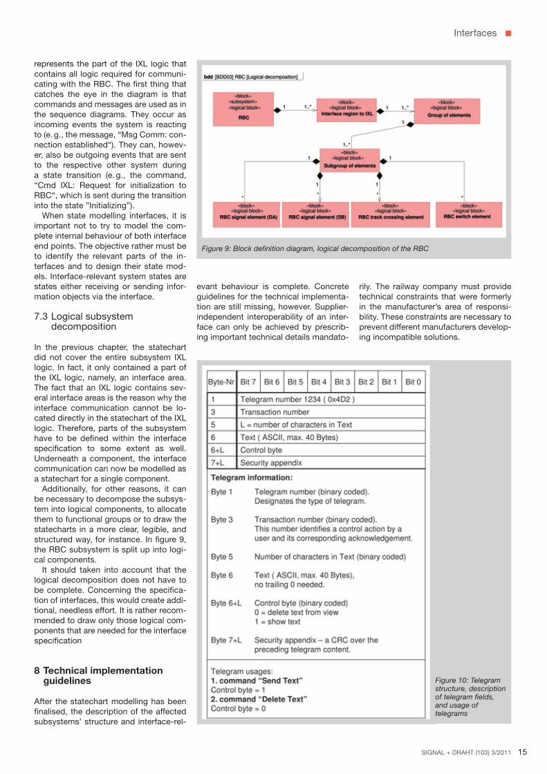
structured way, for instance. In figure 9,
the RBC subsystem is split up into logi-
cal components.
It should taken into account that the
logical decomposition does not have to
be complete. Concerning the specifica-
tion of interfaces, this would create addi-
tional, needless effort. It is rather recom-
mended to draw only those logical com-
ponents that are needed for the interface
specification
8 Technical implementation guidelines
After the statechart modelling has been
finalised, the description of the affected
subsystems’ structure and interface-rel-
Figure 9: Block definition diagram, logical decomposition of the RBC
Figure 10: Telegram structure, description of telegram fields, and usage of telegrams
SD_Lauscher.indd 15SD_Lauscher.indd 15 30.03.11 14:4730.03.11 14:47

SIGNAL + DRAHT (103) 3/2011 16
Interfaces
layers replaceable. One approach could
be, for example, to apply the network
protocol TCP/IP for layers 3-4 and to use
Industrial Ethernet for layers 1-2.
To meet safety requirements, an inter-
mediate safety layer between the trans-
portation layer (4) and the presentation
layer (6) could be specified and devel-
oped by modelling.
SysML facilitates the presentation of
these layers and their interactions with
block definition diagrams and internal
block diagrams.
LITERATURE
[1] OMG Systems Modeling Language (OMG
SysML) Specification,
Internet: http://www.omg.org/technology/
documents/domain_spec_catalog.
htm#OMGSysML, OMG
[2] EN 50126:1999 – Spezifikation und Nach-
weis der Zuverlässigkeit, Verfügbarkeit, In-
standhaltbarkeit und Sicherheit (RAMS), VDE
[3] Weilkiens, T.: Systems Engineering mit
SysML/UML, dpunkt Verlag, 2. Auflage 2008
[4] Friedenthal, S.: A Practical Guide to
SysML – The Systems Modelling Language,
Elsevier, 2008
[5] Zimmermann, H.: OSI Reference Model-
The ISO Model of Architecture for Open Sys-
tems Interconnection, 1980
ments such as RAM(S) requirements.
Additionally, decisions have to be made
regarding the actual technical implemen-
tation at the technical level. The ISO/OSI
reference model [5] is widely used for in-
terfaces (see table 1).
The developed application procedures
reside on layer 7, the application layer.
Due to its layered architecture, the
ISO/OSI model facilitates a clear separa-
tion of network communications respon-
sibilities and tasks. Moreover, it helps to
define and apply industry standards for
individual layers and to make individual
Signalling systems almost exclusive-
ly use telegram-based data interfaces.
Therefore, how to define interface tele-
grams leaving no room for interpretation
is illustrated in the example below.
As an example, the upper part of fig-
ure 10 shows a structure of a data tel-
egram, that is, its byte and bit structure.
This is followed by a description of all
telegram fields in the middle part. Finally,
the ”telegram usage“ is defined for every
telegram instance in the lower part.
In this context, the term telegram us-
age refers to a specific usage of a tele-
gram as a command or a message. The
telegram usage definition describes the
content of all fields that represent the
specific usage as a command or a mes-
sage. In the example shown above, it
only refers to the control byte because
this differentiates between the two tel-
egram usages, ”send text“ and ”delete
text“. Fields are not mentioned here if
their content is variable within the given
telegram usage, the text to be sent, for
example.
Each telegram usage is given a unique
name within the context of the interface.
The name is used in the sequence dia-
grams and statecharts, helping to deter-
mine exactly how a telegram should be
composed for any given task at any time.
8.1 ISO/OSI layers below the application level
The interface requirements developed at
the domain level describe the interface at
the functional level. Besides these func-
tional requirements, an interface also
has to implement non-functional require-
Table 1: The ISO/OSI layers of the reference model
Berner & Mattner Systemtechnik GmbHErwin-von-Kreibig-Str. 3
80807 München
Tel.: +49 (0)89 608090-0
Fax: +49 (0)89 6098182
www.berner-mattner.com
Dipl.-Ing. Thorsten Hiebenthal
Head of Transportation
Berner & Mattner Systemtechnik
Address: Erwin-von-Kreibig-Straße 3, D-80807 München
E-Mail: [email protected]
Dipl.-Ing. Thomas Lauscher
Senior Systems Engineer
Berner & Mattner Systemtechnik
Address: Erwin-von-Kreibig-Straße 3, D-80807 München
E-Mail: [email protected]
Dipl.-Inf. Univ. Christian Fischer
Software Engineer
Berner & Mattner Systemtechnik
Address: Erwin-von-Kreibig-Straße 3, D-80807 München
E-Mail: [email protected]
The authors
SD_Lauscher.indd 16SD_Lauscher.indd 16 30.03.11 14:4730.03.11 14:47


![BOOK-1 THANKS GURUJI24 PAGE-50 - jbbkpm's Blog · PDF fileguruji24.com 2 !p# sd%i]8zgf d}/e}t p5if[uf[ o vfh[ sd%i]8zgf ;f{yl ,fsl5|i :j~5 h[ j5zfxdf\ k[ t[ pc vyjf v\ut sd%i]8z k[p](https://static.fdocuments.in/doc/165x107/5a83572a7f8b9aa24f8eb9a3/book-1-thanks-guruji24-page-50-jbbkpms-blog-2-p-sdi8zgf-det-p5ifuf-o.jpg)