SD Installation and Programming Training Reference Notes
46
SD Installation and Programming Training Reference Notes
Transcript of SD Installation and Programming Training Reference Notes

SD
Installation and Programming
Training Reference Notes

Contents
Introduction ..................................................................................................................................... 4
Configuring the SD Range ................................................................................................................ 5 Passwords ........................................................................................................................................... 5
Using the Local Configuration Pages with the Remote Control ............................................................ 6
Using the Configuration Pages with a USB Mouse .............................................................................. 7
SD Configuration Remote Web Pages ............................................................................................. 8 Configuration Page Structure ............................................................................................................... 8
Softkeys ............................................................................................................................................... 8
Using the Web Pages .......................................................................................................................... 9
On-Board Help Videos ......................................................................................................................... 9
Time and Date Configuration ............................................................................................................. 10
Language ........................................................................................................................................... 11
Advanced Features ....................................................................................................................... 12 Configuring Features ......................................................................................................................... 12
Viewer defaults .................................................................................................................................. 13
SD Display Options ........................................................................................................................ 14
User Accounts ................................................................................................................................ 15 Adding new User Accounts ................................................................................................................ 15
Editing / Modifying User accounts ...................................................................................................... 16
Deleting User Accounts ..................................................................................................................... 16
Camera Setup ................................................................................................................................ 17 Camera Telemetry ............................................................................................................................. 17
Telemetry Capabilities ....................................................................................................................... 18
Serial telemetry settings ..................................................................................................................... 19
Record Settings .............................................................................................................................. 20 Record ............................................................................................................................................... 20
Profile Record ................................................................................................................................... 21
Simple Profile Record ........................................................................................................................ 21
Advanced Profile Record .................................................................................................................. 22
SD Default Record settings: ............................................................................................................... 23
Schedule ........................................................................................................................................ 24 Timer functions .................................................................................................................................. 24
Keyswitch ........................................................................................................................................... 25
Holiday and Weekend ........................................................................................................................ 26
Protect Video ..................................................................................................................................... 27
Network Settings ............................................................................................................................ 28 Network Configuration ....................................................................................................................... 28
Bandwidth Settings: ........................................................................................................................... 28
Live Transmission .............................................................................................................................. 29
2 SD Installation & Programming Training Notes Issue 1.7
© Dedicated Micros 2011
Archiving Video .............................................................................................................................. 30 Archiving Video using Webpages ...................................................................................................... 30
Intelligent PTZ Cameras ................................................................................................................. 31 Oracle Configuration ......................................................................................................................... 31
Configuring Presets ........................................................................................................................... 32
Alarms and Alarm Zones ................................................................................................................ 33 Display of Alarm and Activity Detection Events .................................................................................. 34
Global Actions .................................................................................................................................... 34
Alarm Inputs ....................................................................................................................................... 35
Alarm Zones ....................................................................................................................................... 36
Alarm Zone Actions ............................................................................................................................ 37
E-mail ............................................................................................................................................. 38 Configuring E-mail ............................................................................................................................. 38
Activity Detection ............................................................................................................................ 39 Setting up Activity Detection .............................................................................................................. 39
Activity Response .............................................................................................................................. 40
Activity to Trigger: 'Simple Response'. ............................................................................................... 40
Activity to Trigger: 'Zone' .................................................................................................................... 41
Remote Reporting .......................................................................................................................... 42 NetVu ObserVer Alarm Reporting ...................................................................................................... 43
Sounding Alarms in NetVu ObserVer ................................................................................................. 43
Audio Features of SD ................................................................................................................... 44
Displaying and Recording Text Data .............................................................................................. 45 Keywords ........................................................................................................................................... 46
3 SD Installation & Programming Training Notes Issue 1.7
© Dedicated Micros 2011

Introduction
At the very heart of Dedicated Micros new SD Range, is a philosophy to provide the widest range of video surveillance solutions possible.
The SD Range provides flexibility and scalability whilst ensuring that existing investments are protected.
Dedicated Micros belief is that any new CCTV developments, must work seamlessly with existing systems without the need for a complete refit. To simply illustrate this, DM’s founding core principles of NetVu Connected, is that everything must work together, both old and new.
Investing in new technology solutions, provides added and enhanced capability, but wherever possible, does not force obsolescence on existing infrastructure, This flexibility and scalability ensures that existing investments are protected.
Product choice is no longer based on features but on key capabilities of recording and video management as all SD Products have the same enhanced features.
The SD of products provide the widest range of capabilities
• Seamless integration of existing or newly deployed analogue and up to 4 x IP Cameras, either DMs’ own generation or selected 3rd party for both Recording and Viewing (8 & 16 channel units only)
• Decoding to multiple viewing clients in real-time, viewed both locally and remotely to match the network performance and capability that has been provided.
NetVu Connected Technology Guarantees interoperability between all products in the range.
• All NetVu Connected Clients including NetVu ObserVer, NetVu Console and Pick-a-Point can seamlessly control any NetVu Connected DVR and Server including the entire SD range.
The SD range of products provides enhanced performance, delivered through the latest Gen3 Architecture. The enhanced system performance has been provided in all of these crucial areas performance includes:
• Improved Disk performance◦ SATA disks provide 8x Read/Write Speeds of PATA/IDE
• Increased Processor Power and Memory Enhancements◦ more than double the processing power◦ 64bit RAM doubles memory throughput
• Enhanced Codec Capability◦ latest generation Chipwrights ViSP devices deliver improved performance through greatly
increased clock speeds, memory and computation power• Improved Bus Architecture
◦ separate buses for Disk Drive and other peripherals increases total data throughput.
4 SD Installation & Programming Training Notes Issue 1.7
© Dedicated Micros 2011
Configuring the SD Range
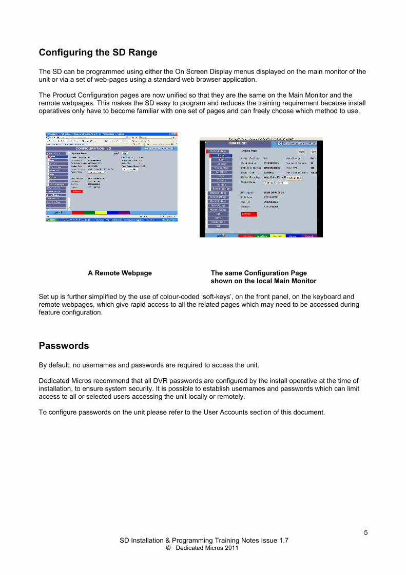
The SD can be programmed using either the On Screen Display menus displayed on the main monitor of the unit or via a set of web-pages using a standard web browser application.
The Product Configuration pages are now unified so that they are the same on the Main Monitor and the remote webpages. This makes the SD easy to program and reduces the training requirement because install operatives only have to become familiar with one set of pages and can freely choose which method to use.
A Remote Webpage The same Configuration Pageshown on the local Main Monitor
Set up is further simplified by the use of colour-coded ‘soft-keys’, on the front panel, on the keyboard and remote webpages, which give rapid access to all the related pages which may need to be accessed during feature configuration.
Passwords
By default, no usernames and passwords are required to access the unit.
Dedicated Micros recommend that all DVR passwords are configured by the install operative at the time of installation, to ensure system security. It is possible to establish usernames and passwords which can limit access to all or selected users accessing the unit locally or remotely.
To configure passwords on the unit please refer to the User Accounts section of this document.
5 SD Installation & Programming Training Notes Issue 1.7
© Dedicated Micros 2011

Using the Local Configuration Pages with the Remote Control
Press the MENU key to open the menus on screen. The currently open menu will be shown with a red cursor next to it.
Press the Down key to highlight the next menu in the list, press OK to open the highlighted menu.
Press the Right key to highlight the first editable parameter on the page.
Use the Left and right keys to move the cursor (highlighted field) between editable fields.
Use the Up and Down keys to change the settings within an editable field.
Use the OK key to accept a new setting.
Use the coloured keys to select options highlighted in that colour i.e. red key to select the red option.
Press EXIT or LIVE to exit the menus.
Note: The 'OK' key emulates the left button on a USB Mouse. Therefore, as with a USB Mouse, 'Double Clicking' the 'OK' key will access the selected field.
6 SD Installation & Programming Training Notes Issue 1.7
© Dedicated Micros 2011
Using the Configuration Pages with a USB Mouse
Enter the configuration Menus either by pressing the MENU key on the SD Remote control or the MENU button on the KBC keyboard.
Navigate the pages by clicking on the tabs on the left of the main page.
Highlight an editable field by clicking directly on it.
Use the drop down menu to change the setting.
Note: The selected item in the drop down list is highlighted.
Navigating away from a page (clicking on a different tab on the side panel) will automatically save the new settings.
Use the ‘Cancel’ button to revert to the previous settings and then navigate away.
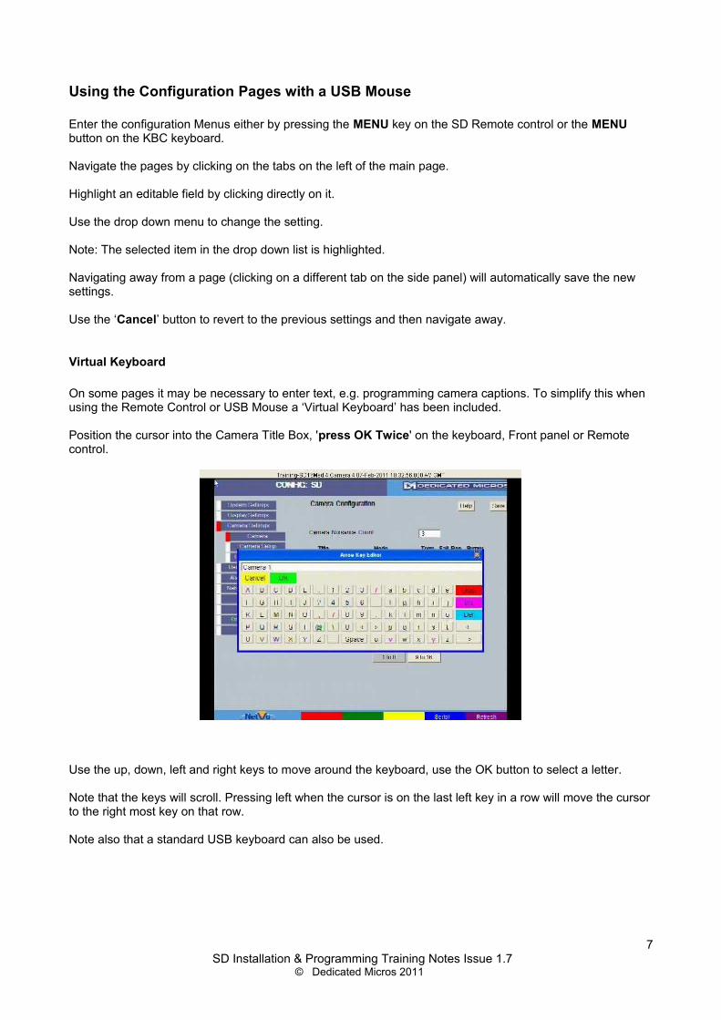
Virtual Keyboard
On some pages it may be necessary to enter text, e.g. programming camera captions. To simplify this when using the Remote Control or USB Mouse a ‘Virtual Keyboard’ has been included.
Position the cursor into the Camera Title Box, 'press OK Twice' on the keyboard, Front panel or Remote control.
Use the up, down, left and right keys to move around the keyboard, use the OK button to select a letter.
Note that the keys will scroll. Pressing left when the cursor is on the last left key in a row will move the cursor to the right most key on that row.
Note also that a standard USB keyboard can also be used.
7 SD Installation & Programming Training Notes Issue 1.7
© Dedicated Micros 2011
SD Configuration Remote Web Pages
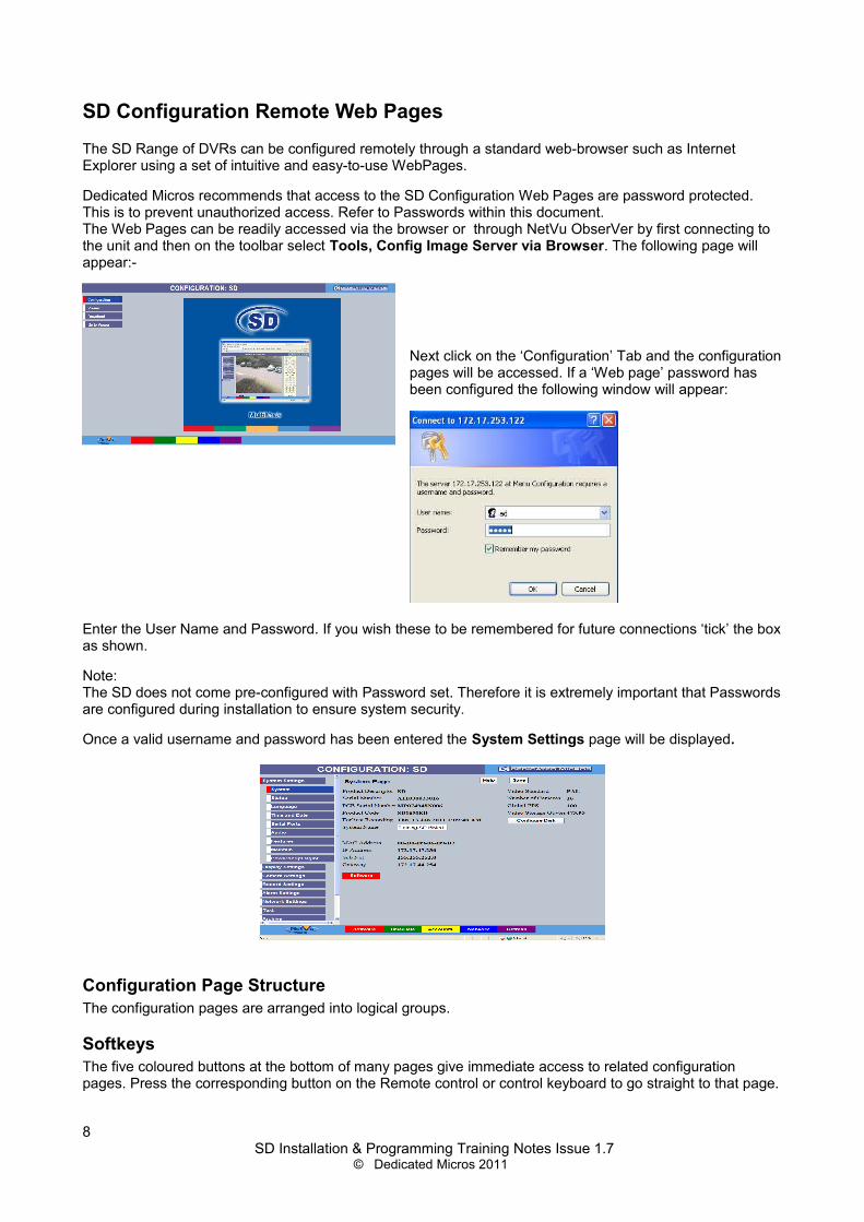
The SD Range of DVRs can be configured remotely through a standard web-browser such as Internet Explorer using a set of intuitive and easy-to-use WebPages.
Dedicated Micros recommends that access to the SD Configuration Web Pages are password protected. This is to prevent unauthorized access. Refer to Passwords within this document.The Web Pages can be readily accessed via the browser or through NetVu ObserVer by first connecting to the unit and then on the toolbar select Tools, Config Image Server via Browser. The following page will appear:-
Next click on the ‘Configuration’ Tab and the configuration pages will be accessed. If a ‘Web page’ password has been configured the following window will appear:
Enter the User Name and Password. If you wish these to be remembered for future connections ‘tick’ the box as shown.
Note:The SD does not come pre-configured with Password set. Therefore it is extremely important that Passwords are configured during installation to ensure system security.
Once a valid username and password has been entered the System Settings page will be displayed.
Configuration Page StructureThe configuration pages are arranged into logical groups.
SoftkeysThe five coloured buttons at the bottom of many pages give immediate access to related configuration pages. Press the corresponding button on the Remote control or control keyboard to go straight to that page.
8 SD Installation & Programming Training Notes Issue 1.7
© Dedicated Micros 2011

Using the Web PagesImportant: Any changes made to settings are actioned as soon as another page is selected or the same page is reselected.
Note that there is also a SAVE button on all pages with changeable settings. This allows the install operative to save any changes on that page without Navigating to another page.
The Refresh button can be pressed to reverse any changes that have been made in error.All the settings on the page will revert to how they were set when going on to the page. This is a useful safety feature and will help avoid programming errors.
On-Board Help VideosThe New SD (with front Panel Control) includes on board help videos for assistance on both User and Configuration features. Accessible from both the local and remote viewer the help videos cover all major operation and configuration topics including: Basic Live and Playback control, telemetry control, alarm configuration, event reviewing, network settings and archiving.
9 SD Installation & Programming Training Notes Issue 1.7
© Dedicated Micros 2011
Time and Date Configuration
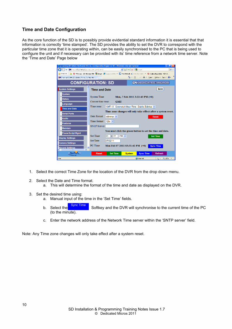
As the core function of the SD is to possibly provide evidential standard information it is essential that that information is correctly ‘time stamped’. The SD provides the ability to set the DVR to correspond with the particular time zone that it is operating within, can be easily synchronised to the PC that is being used to configure the unit and if necessary can be provided with its’ time reference from a network time server. Note the ‘Time and Date’ Page below
1. Select the correct Time Zone for the location of the DVR from the drop down menu.
2. Select the Date and Time format.a. This will determine the format of the time and date as displayed on the DVR.
3. Set the desired time using:a. Manual input of the time in the ‘Set Time’ fields.
b. Select the Softkey and the DVR will synchronise to the current time of the PC (to the minute).
c. Enter the network address of the Network Time server within the ‘SNTP server’ field.
Note: Any Time zone changes will only take effect after a system reset.
10 SD Installation & Programming Training Notes Issue 1.7
© Dedicated Micros 2011
Sync Time
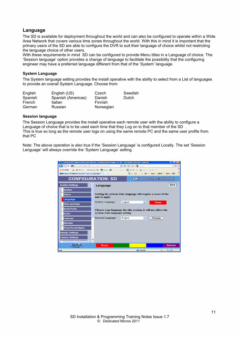
LanguageThe SD is available for deployment throughout the world and can also be configured to operate within a Wide Area Network that covers various time zones throughout the world. With this in mind it is important that the primary users of the SD are able to configure the DVR to suit their language of choice whilst not restricting the language choice of other users.With these requirements in mind SD can be configured to provide Menu titles in a Language of choice. The ‘Session language’ option provides a change of language to facilitate the possibility that the configuring engineer may have a preferred language different from that of the ‘System’ language.
System LanguageThe System language setting provides the install operative with the ability to select from a List of languages to provide an overall System Language. Choose from:
English English (US) Czech SwedishSpanish Spanish (Americas) Danish DutchFrench Italian FinnishGerman Russian Norwegian
Session languageThe Session Language provides the install operative each remote user with the ability to configure a Language of choice that is to be used each time that they Log on to that member of the SD .This is true so long as the remote user logs on using the same remote PC and the same user profile from that PC
Note: The above operation is also true if the ‘Session Language’ is configured Locally. The set ‘Session Language’ will always override the ‘System Language’ setting.
11 SD Installation & Programming Training Notes Issue 1.7
© Dedicated Micros 2011

Advanced FeaturesThe SD has the ability to provide a number of Advanced features which further enhance the integration of the DVR. Features such as:Remote Reporting; E-mail on alarm or system event; Web cam support etc.These enhanced features are primarily activated using the Features Webpage this ensures that only the required features are enabled thus ensuring that the SD only processes required features.
Configuring FeaturesAll Advanced features must be activated within the Features Webpage any additional settings i.e. e-mail server address are configured within specific webpages for that feature.
1. Navigate to the Features webpage (see below)
2. Check the feature that is required to enable it.
3. Select Save
4. Navigate to the Individual configuration pages for the enabled feature.
Note : After selecting a Feature, The SD Unit may require a reset for these features to operate.
12 SD Installation & Programming Training Notes Issue 1.7
© Dedicated Micros 2011

Viewer defaultsThe viewer default page is used to determine the default format of the local monitor and remote viewers including the Multiscreen format. As the configuration of this page is dependant on each particular installation and end user specifications each menu within this page is explained below:
Default image format Is the image format (MPEG4 or JPEG) that will be requested from the server locally and remotely.
Default Image Req Provides the install operative with the ability to select the desired quality of video stream that is to be requested from any connected 'IP Cameras / Video sources' for display or, the Live transmission from the SD should the remote viewer be used. The actual Video Steam is defined by the Installation Operative by navigating to the following Configuration page: Network settings > Live Trans on either the SD or the Video source.
Default Quad Req provides the install operative with the ability to match the ‘desired’ quality of image with the available bandwidth and display format.Consider one quadrant of a Quad display compared to a FULL screen. The resolution of the ‘small’ quadrant of the Quad screen does not need to be as high as that of a FULL screen display to provide an image of the required quality. This can assist in reducing network traffic when the remote viewer is used or an IP camera is to be displayed on the Main Monitor.
Default Multi Req As with the 'Default Quad Req' this option allows the Transmission required to produce a suitable quality display to be matched to the Display type and/or the transmission bandwidth available.
Default Multi display provides the install operative with flexibility with regards to the number of cameras that will be displayed in multi screen.
Note: If the End User is only to be able to select one Multi screen format e.g. 9 way, then that format should be selected here. If the user is to be able to select from a number of Formats, then select 'None'.
Video Output Mode Select from PAL reduced or PAL default to match the format of the display
13 SD Installation & Programming Training Notes Issue 1.7
© Dedicated Micros 2011

SD Display OptionsThe Display page provides the Install operative with the ability to determine how the Main and Spot monitors are displayed. This includes sequencing of Main and Spot Monitors and features such as Custom Segment Set up.I
Enable Custom Setup. This allows a multiscreen to be amended, to show cameras in the positions that an end user may specify.If the cameras are always to be shown in the correct sequencial order, then this option should be unticked.
Camera selection switches to full screenIf this option is selected, then when a multi-screen is displayed and a camera is selected – the selected camera will be shown full screen. If the option is not selected, the multi-screen will 'start' from the selected camera.
SoftKey Timeout.This option can be amended to increase or decrease the number of seconds that the on-screen softkeys are displayed on the Main monitor.
14 SD Installation & Programming Training Notes Issue 1.7
© Dedicated Micros 2011

User AccountsUser accounts set the usernames and passwords access for FTP, Telnet and webpages. Only one username and password can be set for each function. To edit an existing System Account complete the following:
1. Select Display Settings-> User Accounts, the following screen is displayed. Note the page may take several seconds to open as the data from the unit is being downloaded for display.
2. The current usernames and passwords can be edited from this web page.
IMPORTANT It is highly recommended that these usernames and passwords are configured as soon as possible following installation and system handover in order to maintain system security.
Note: Please ensure all configured Usernames and Passwords are retained as loss of this information may result in the unit being returned to Dedicated Micros.
Adding new User Accounts
The Video Account section allows operators to be added to the system. When a user is added it will be necessary to enter the correct username and password when connecting to the device using the NetVu ObserVer.
1. Select Console Settings -> User Accounts. Note the page may take several seconds to open as the data from the units is being downloaded for display.
2. Select Local Users from the list
15 SD Installation & Programming Training Notes Issue 1.7
© Dedicated Micros 2011
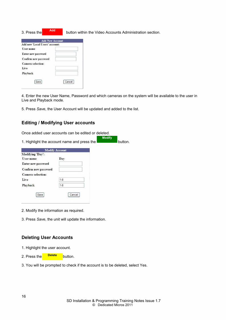
3. Press the button within the Video Accounts Administration section.
4. Enter the new User Name, Password and which cameras on the system will be available to the user in Live and Playback mode.
5. Press Save, the User Account will be updated and added to the list.
Editing / Modifying User accounts
Once added user accounts can be edited or deleted.
1. Highlight the account name and press the button.
2. Modify the information as required.
3. Press Save, the unit will update the information.
Deleting User Accounts
1. Highlight the user account.
2. Press the button.
3. You will be prompted to check if the account is to be deleted, select Yes.
16 SD Installation & Programming Training Notes Issue 1.7
© Dedicated Micros 2011
Add
Modify
Delete

Camera Setup
Manual adjustments to both Colour and Contrast can be made on images from analogue cameras. These adjustments are made within the Camera Setup page
Camera Telemetry
The desired telemetry protocol for each Camera, can be chosen from an extensive list.
The list of 3rd party dome and telemetry protocols comprises :-
Dennard Dennard-C DM-RS232 DM-RS485 BBV-CPanasonic WV-CS600 & WV-CS850 Pelco P PhilipsSamsung Sanyo Sensormatic Ultrak VantageVCL Vicon Vista PD 485 DM-Serial Baxall-CMark Mercer Ernitec Pelco-C Pelco-D KalatelJVC Philips-232 DM Coax
Philips 232 AD Matrix AD168 MatrixBBV Matrix VCL Matrix BBV RS485
DM-IP AXIS-IP JVC-IP
17 SD Installation & Programming Training Notes Issue 1.7
© Dedicated Micros 2011

Telemetry CapabilitiesThe SD is equipped with two RS485 ports (Serial Ports 3 and 4) that can be used for telemetry transmission. Coaxial transmission either BBV, Dennard or Pelco-C or Baxall can be set, camera by camera. Support for a number of 3rd party matrix switchers (VCL, BBV, AD168, AD-Matrix) is also provided, making the SD very flexible in the telemetry applications that can be met.
If using Serial telemetry, then a quick link to Serial port configuration is available at the bottom of the screen.
Simply select the blue softkey or click on
18 SD Installation & Programming Training Notes Issue 1.7
© Dedicated Micros 2011
Serial

Serial telemetry settingsIf Serial telemetry is to be utilised then the configuration of the Serial port has to be completed within the System Settings > Serial Ports page (see example below).
1. Select the Serial Port that is to be used
2. Select the ‘Port Config’ from the drop down list.a. Select ‘telem’ for telemetry configuration
3. Define the interface type. Select from:a. RS232, RS485 or RS422.
4. Select the correct Baud Rate, Data, Parity, Stop Bits and Flow Control for the camera that you are connecting to.
5. Finally identify the protocol that is to be used from the drop down list (should be the same as the Protocol selected on the Camera telemetry Page) and Select ‘Save’
Note: An example application is explained, within the Annex section of this document
19 SD Installation & Programming Training Notes Issue 1.7
© Dedicated Micros 2011

Record SettingsThe SD provides a varied range of recording Capabilities
SD seamlessly integrates Analogue Camera recording and playback. The New SD will, following a forthcoming software release, be able to accept up to 4 IP
video steams from IP devices. SD is MultiMode Recording Capable
Dynamically-switchable resolution, record-rate & compression per camera, switchable on an event, a schedule or using a keyswitch
RecordThe record page provides a facility for easy off the shelf set-up of all analogue cameras to one of three default recording profiles.
1. Select from the drop down menu’s the record provide that you wish to be applied to all cameras.a. XX Rate Multimode
i. Switches an MPEG recording per channel switching to JPEG recording per channel on event.
b. XX Rate MPEGi. This will apply a MPEG record profile to all channels
c. XX Rate JPEGi. This will apply a JPEG record profile to all channels
Note: XX refers to the Low, Medium or Normal Rate record settings which are detailed below:
Normal Rate Recording provides 5pps per camera in MPEG4 or 1pps in JPEGMedium Rate Recording provides 2pps per camera in MPEG4 or 0.5pps in JPEGLow Rate Recording provides 1pps per camera in MPEG4 or .25pps in JPEG
2. Select the Duration of recording you wish the DVR to provide.a. A reduced Record Duration can be selected by 'increasing' Record Quality settingsb. An Increased Record Duration can be selected by 'decreasing' the Record Quality setting
20 SD Installation & Programming Training Notes Issue 1.7
© Dedicated Micros 2011

Profile Record
For applications demanding individual record settings on a Camera-by-Camera basis, switching on Event and Schedule, then Profile Recording can be used
Two ‘levels’ of configuration complexity are available ‘Simple’ and ‘ Advanced ’:
Simple Profile RecordThe Simple Profile Record consists of pre-defined profiles that the Install operative may choose from. To configure using ‘Simple’:
1. Select the Camera / Channel that you wish to configure
2. If any Pre Trigger (pre alarm) is required then navigate to Record settings . JPEG Pre Trigger configuration page and select ‘Enable’ for each camera where this feature is required. The Pre-trigger duration (secs) will be calculated and displayed in an un-editable format (any direct editing of the Pre trigger Duration must be done within the ‘ Advanced ’ settings)
Note: Pre trigger is only available when event recording is set to JPEG.Note: The Pre trigger duration is calculated using the event PPS rate. The higher the PPS rate the
lower the Pre-trigger duration.
3. Next develop the record profile from:a. Compression type MPEG4 or JPEGb. Pictures Per Second PPS (½ Real-Time etc, 6 PPS etc)c. Quality (5 Levels –Maximum to Very Low)
4. If MultiMode recording is to be utilised it may be configured:a. On a Camera by Camera Basisb. In Normal or Eventc. On a schedule
21 SD Installation & Programming Training Notes Issue 1.7
© Dedicated Micros 2011

Advanced Profile RecordThe Advanced Profile Record provides the ability to be specific on exactly what an individual record profile is. To configure using ‘ Advanced ’:
1. Select ‘ Advanced ’ in the Menu view field. An example of the Advanced page is shown below:
2. Select the Camera / Channel that you wish to configure
3. When using MPEG4 the number of P-frames for every I-frame can be configured by amending the ‘gop’ (Group Of Pictures – This determines how often the I-Frame is recorded)
a. In the example above the GOP is set to 5 and the pps is set to 5 this will result in an I frame being recorded every second.
4. If any Pre-Trigger (pre alarm) is required enter the ‘ Pre-Trigger Duration’ (JPEG Event Recording only)
5. Next develop the record profile from:a. Compression type MPEG4 or JPEGb. Resolution QCIF to 4CIFc. Quality of MPEG4 images (bit rate bps)d. Quality of JPEG Images (file size KBytes)e. Pictures Per Second PPS
6. If MultiMode recording is to be utilised it may be configured:a. On a Camera by Camera Basisb. In Normal or Eventc. On a schedule
Note: If the Advanced page has any setting changed after navigating from Simple, the Simple page can not be reselected. If the simple page is to be re-accessed a ‘Global Profile’ must be selected and saved from the ‘record’ page. Then the Profile record page can be accessed with the ‘Simple’ option available.Performing this operation will ‘clear’ any ‘ Advanced ’ or ‘simple’ settings that have previously made.
Note: The number of PPS that the SD can perform is determined by the maximum performance of the Hardware codecs resident in the SD. Each Hardware codec can provide 25pps at 4CIF however this performance is shared between the connected cameras.To confirm which cameras are connected to which codec navigate to System Settings> Settings >Unit status within the configuration pages where this information is displayed.
It is important to ensure that the Maximum PPS is not exceeded during Normal or Event recording.
22 SD Installation & Programming Training Notes Issue 1.7
© Dedicated Micros 2011

SD Default Record settings:
The SD is available in 4, 8, 16 and 32 camera models and is designed to be easily configured.A comprehensive digital recording solution, the SD is a stand-alone high performancerecording system offering reliable, networked, scalable CCTV at an affordable price.Its size and design make it the ideal desktop solution and perfect for installations where high recordrates and network capabilities are required.
The Default record settings on the SD are MPEG 2CIF, 6pps 360Kb/sec
The SD provides up to 100pps @ 4CIF
The Default record settings of the SD are dependant on the model selected i.e. the Normal, Medium or Low
MPEG JPEGNormal 5pps 1ppsMedium 2pps 0.5pps (1picture every 2 seconds)Low 1pps 0.25pps ( 1 picure every 4 seconds)
23 SD Installation & Programming Training Notes Issue 1.7
© Dedicated Micros 2011

Schedule
The SD is equipped with a powerful scheduler which can set and unset alarm and Activity Detection responses and alter the recording rates of cameras to meet different site operating modes during the day, night and weekend.
Timer functionsThe schedule option allows the install operative to define different record profiles at different times / days. To configure the schedule:
1. Navigate to the Schedule page (see example below)Note: 00:00 means 24Hr Day Mode
2. Define the start of day and the start of nighta. For each day of the week
24 SD Installation & Programming Training Notes Issue 1.7
© Dedicated Micros 2011

KeyswitchA Keyswitch can be used to Set and Unset the system, changing the record profile of cameras and also enabling and disabling the alarms. Note that the Keyswitch cannot be used in conjunction with the Schedule facility. To configure the Keyswitch:
1. Select ‘enable’2. Select the contact that the keyswitch is assigned to (one of 20 contacts)3. Select the Alarm Zone that the keyswitch is within.4. Define the keyswitch as N/O or N/C, simply ‘tick’ the box5. If End of line monitoring is to be configured on the keyswitch then ‘tick’ the box.
See example below:
Note: If keyswitch is enabled, then the schedule configuration option will disappear.Note: If contact 20 is not to be used as a keyswitch then select ‘Disable’ at keyswitch option. Alarm Input
20 will now be available as an alarm input within the ‘Alarm Inputs’ webpage.
25 SD Installation & Programming Training Notes Issue 1.7
© Dedicated Micros 2011

Holiday and WeekendMultiple Holiday periods can be defined and Weekends may be defined to Start and End at the choice of the install operative.
Holidays
To add a holiday:
1. Enter the data of the holiday2. Select ‘Add’3. Continue to add dates to cover the full holiday period.
To delete a holiday:
1. Highlight the date that is to be deleted2. Select ‘Delete’3. Continue to delete dates top cover the period that is to be removed.
Weekends
To configure weekends:
1. ‘Enable’ the Weekends box2. Define the start of the weekend3. Define the end of the weekend.4. select ‘Save’
26 SD Installation & Programming Training Notes Issue 1.7
© Dedicated Micros 2011

Protect VideoMultiple Selected images can be protected, via local and remote access, from being overwritten. This helps to prevent important periods of video capture from being overwritten.
To protect video:
1. Enter the Start Date and time of the Video2. Enter the End date and time of the Video3. Enter the period that the video is to be protected for.
4. Select the soft key5. Ensure that the Protected period is added to the List
To Unprotect video:
1. Generate a list of the protected Video for the period you are interested ina. Enter ‘List From Date’ and ‘time’b. Enter ‘List To date’ and ‘time’c. Select ‘Reload list’ button
2. Highlight the video that is to be Unprotected
3. Select the softkey.4. Ensure that the Unprotected period is removed from the List.
27 SD Installation & Programming Training Notes Issue 1.7
© Dedicated Micros 2011
Protect
Unprotect

Network SettingsThe SD provides easy-to-configure network settings to aid with reducing installation time.The SD provides a DHCP client for integration into a Dynamic IP (DHCP) network. This greatly simplifies the process of deploying the SD on a network.The SD can be configured with a static IP address, this is the recommended method of installing the SD in remote monitoring and event reporting applications. This feature ensures that Remote Maintenance, Viewing and Administration of the SD is achievable.The SD network settings can be configured to match most Network types to ensure the most efficient deployment of the Range within a network and to maintain ‘Network friendliness’
Network Configuration
All network settings are made within the Network page, this includes the IP address.The SD has an in-built DHCP client. This allows the DVR to be used in a network with a DHCP server (i.e dynamic IP)
Static IP is preferred, particularly where remote-access or dial out on alarm is required
Bandwidth Settings:
Ethernet MTU (Max Transmission Unit = Max packet size (default 1500 bytes)For LANs use 1500, ADSL uses either 1492 or 1458,ISDN normally uses 576 Bytes.
Max Transmission Rate kbytes sec defines the bandwidth limit of how much data the DVR will impose on the connected network.
Max Transmission Timeout (ms) is the Re-Transmit Timeout period. This is the time the unit will wait before resending a packet if an acknowledgement is not received. When making a connection across a WAN link this figure needs to be increased and should match the timeout figure for the router.
Note that there is no Custom setting as each value can be changed away from the default to match each network independently.
28 SD Installation & Programming Training Notes Issue 1.7
© Dedicated Micros 2011

Live TransmissionThe SD can be configured to provide multiple simultaneous independent Transmission streams, each with its own viewing parameters. Each stream can be optimised for users who are connected allowing a different viewing profile to be set for users connecting over Local, Wide Area and Low Bandwidth Connections
– LAN– WAN– Very Low Bit Rate (VLBR) connections e.g. Mobile.
The SD can even Transcode high quality recorded images into a stream that matches the connection bandwidth between the SD and the remote viewing clients. This means that the viewing of recorded video can be tailored to suit the available network bandwidth.
– The original recording quality is not affectedThe settings for transmitted video streams to NetVu Connected clients such as NetVu ObserVer or NetVu Console, are accessed within the ‘Live Trans’ page. The High, Medium and low settings for JPEG and MPEG4 define the stream parameters when selected from within the viewing clients
In the example below the 'MPEG High LAN stream' will provide a Live stream to the requesting client of:
2CIF, 1536kbits, Real Time, GOV, CBR, 25.
i.e. when a single stream is requested the Bandwidth will be 1536kbits.
Six Viewing Profiles can be set on each SD unit, enabling video transmissions to be optimised to match Network Connection Bandwidth. The transmission profiles can be defined by the installer from:
– High, Medium or Low MPEG and JPEG
– Resolution• 4CIF to QCIF
– Quality• Bit rate (MPEG)• File size (JPEG)
– MPEG Compression type• RAW
• This includes an initial I-frame and then P-frames only• Ideal for VLBR connections• Default for low VLBR transmission profile
• GOV (Group of Video)• This includes all I-frames and P-frames
Remember that the bandwidth limit in the Network Configuration pages will have priority over the settings shown here. If update rate or quality is not what is expected, firstly check that the bandwidth limit has not been set too low to achieve the quality level or update rate required.
29 SD Installation & Programming Training Notes Issue 1.7
© Dedicated Micros 2011

Archiving VideoThe SD provides the ability to archive a period of video to USB, CD-R or DVD-R via the configuration webpages. This is particularly useful where remote access is available and a period of video requires to be archived. This feature only requires that the record medium is physically placed into or, connected to the Unit.
Archiving Video using Webpages
1. Navigate to the Archive webpage
2. Select the medium to which the video is to be archived.
3. Enter the Start and End Date/Time.
4. If the Viewer is to be included on the archive then check the ‘Viewer’ box.
5. Insert the medium as required
6. Select ‘Check Media’
7. Select ‘Archive’
8. When the archive is complete a message stating ‘Complete’ will be displayed within the ‘Status’ field.
Note: The archive will include all connected Cameras.
30 SD Installation & Programming Training Notes Issue 1.7
© Dedicated Micros 2011

Intelligent PTZ CamerasThe Oracle Dome and Infiniti Cameras integrate directly with the SD. This integration provides access to a number of features such as:
• Configuration file for the Camera is held on the DVRo Provides rapid deployment of New / replacement hardware.
• Configuration of the Dome is via the Webpages of the DVRo For ease of configuration of Presets, sectors, Patrols etc.
Oracle Configuration Each Oracle Dome needs to be ‘assigned’ to the channel that it is connected to before additional configuration can take place. To do this:
1. Navigate to the ‘Status’ webpage as shown below:
2. From the drop down menu select the channel that the Oracle dome is connected to.
3. Select ‘Save’.
4. Note the options to configure the actual dome are now displayed.
31 SD Installation & Programming Training Notes Issue 1.7
© Dedicated Micros 2011

Configuring Presets
The Oracle Dome can be configured with 99 preset camera positions. To configure each preset via the SD Webpages complete the following steps:
1. Navigate to the ‘Presets’ Webpage. See below:
2. Select the Preset position that you wish to Store from the ‘Preset’ field.
3. Enter a Name for the preset In ‘Preset Name’ field.
4. To select the view that you wish to be displayed use the control to drive the dome to the desired view and the + and – icons to Zoom the view in and out as desired.
5. When the desired view is displayed select the Softkey.
6. Confirm that the desired preset has been stored by driving the Dome away from the stored view
Now select the ‘Preset’ number and then select the Softkey. The Dome should now drive to the stored view for that preset.
32 SD Installation & Programming Training Notes Issue 1.7
© Dedicated Micros 2011
Store
Goto

Alarms and Alarm ZonesThe SD provides Comprehensive Alarm Management. The System can be set on Schedule, Keyswitch or Remote from Authorised Operator. The powerful Alarm Zone capability minimises false activations and improves system reliability.
The SD provides Alarm Reporting to Remote Video Response Centre (RVRC). Tamper Proof Alarm Inputs can be configured for increased system security. Nuisance Count & Stuck Timers are provided to reduce false Alarm activation. Primary & Secondary Alarm Signalling Paths increase reliability of reporting. All fully compliant with British Standard BS8418
Comprehensive System Status Information is viewable both locally & remotely. This helps to reduce system commissioning and maintenance costs.
Comprehensive alarm response capability is a common feature set across the SD :-• Alarm Inputs
o The SD supports 20 Normally open/closed tamper proof alarm inputs or a Global keyswitch with specific inputs configurable as entry/exit alarms
• 32 Easily configurable Alarm Zoneso Enabling Advanced alarm detection & false alarm rejection
• Activity Detectiono Built in as standard & configurable on every camera including domes!
• Virtual Alarmso Ideal for Advanced custom solutions via TCP/Ethernet
• Alarm Reportingo To RVRC
33 SD Installation & Programming Training Notes Issue 1.7
© Dedicated Micros 2011

Display of Alarm and Activity Detection EventsAlarm and Activity Detection events can be displayed on the Main monitor.
This is set in the Alarm Settings, Global Actions menu page.
Global Actions
Alarm Display Mode can be selected to ‘Jump to Primary’. This will cause the main Monitor to switch on Alarm or Activity detection events
Revert Display Mode After Alarm defines what happens to the Main Monitor after the event has finished
Alarm Image Protection periods can be set, so that images are not overwritten and are accessible for review and archiving for a set number of days
34 SD Installation & Programming Training Notes Issue 1.7
© Dedicated Micros 2011

Alarm InputsThe SD provides the following alarm input capabilities:
– 20 Inputs via a 25 way D connector• Each input can be Normally Open/ Normally Closed
– EOL Monitoring• Detects open/short circuit cables
– Nuisance Count• Detects repeated false activations
– Stuck Timer• Detects alarms that are in an active state for a prolonged period
– Pulse Extension• Used to prevent double triggers on an alarm
The Alarm Input web page is demonstrated below:
Note: If Alarm input 20 is not displayed. This is because it is set as a keyswitch input at factory default. To enable as a standard Alarm input then refer to ‘Schedule / Keyswitch’ section of this document.
35 SD Installation & Programming Training Notes Issue 1.7
© Dedicated Micros 2011

Alarm ZonesAlarm Zones allow events such as contact closures or Video Motion Detection (VMD) to becombined to produce powerful alarm responses.
Up to 32 Alarm Zones can be programmed.
Inputs can be :-Contact inputs (known as Alarm Inputs, 20 Max.)Activity on any cameraVirtual AlarmsSystem Events (Disk Low, Disk Full or Panic Button Press)Keywords
Each Alarm Zone can be scheduled to be enabled during the Day and/or Night and/orWeekend or 24-hours.
The Alarm Zone web page is shown below:
Each Alarm Zone can be configured during installation to determine when the Zone is active For example:Alarm 24Hr All the timeOn a schedule Day
NightWeekend
The Alarm Zone can also be configured to show if the Zone is on an Entry or Exit route. If it is then:
1. The Entry Time and Exit Time should be entered 2. The Entry Route Zone and / or the Exit Route Zone should be ‘ticked’.
The Alarm Zone can be configured to provide an Exit Terminator1. Tick this option for this zone to terminate the exit timer and set the system
The Alarm Zone can be configured to provide an Entry Initiator1. Tick this option for this zone to start an entry timer to allow access to the unset zone e.g. keypad or
control panel. a. This allows Zones on the entry route to be passed through without creating an alarm
condition.
36 SD Installation & Programming Training Notes Issue 1.7
© Dedicated Micros 2011

Alarm Zone Actions
When an Alarm Zone is activated there are a large number of responses that the Zone can be configured to perform. This comprehensive Alarm Handling capability is a common feature across the SD range. The following actions can be programmed:
Change the record profile (On a Primary and any other Cameras Select to configure). Alarm reporting (to RVRC)Goto PresetClose a RelayPlay Audio message (up to 32 pre recorded messages)Send an E-mail (with or without a .jpg image attached)Archive Alarms and Automatically protect Alarm images
And lots more…..
37 SD Installation & Programming Training Notes Issue 1.7
© Dedicated Micros 2011
Cam Options

E-mailThe SD can be configured to send an e-mail to advise of ‘events’ such as Alarms and Activity. This provides additional notification other than to Remote receiving centre. System Events can generate e-mail notification to allow events such as Camera Fails and System Start ups to be acted upon by engineering personnel.An image of the defined event can also be e-mailed. This provides additional assistance with prioritising events which will ultimately improve response to event situations.
Configuring E-mailTo configure e-mail details complete the following steps:
1. Check the ‘Email reporting’ option within the Features webpage (see Advanced features)
2. Check the ‘Email reporting’ option within the ‘Zone Actions’ webpage for each zone that is to generate an e-mail.
3. If the email is to include an image from the Primary camera of that zone then check the ‘E_mail Image’ option for each zone that is to generate an e-mail.
4. Navigate to the E-mail configuration page
a. When in ‘Zone Actions’ web page select the softkey.
5. Populate Configuration page with details as requested. Below is an example of these settings.
6. Select when the mail is to be senta. Start up, Alarm, Camera Fail or Activity event
7. Select what will be contained within the maila. Thumbnail, Hi, Med or Low quality
8. Select ‘Save’
9. Once the configuration is complete reset the DVR via the ‘Maintain’ webpage to activate the E-mail feature.
38 SD Installation & Programming Training Notes Issue 1.7
© Dedicated Micros 2011
E mail

Activity DetectionActivity Detection has enhanced configurability for improved detection and reduction in the number of false alarms.A 16 x 16 (PAL) rectangular grid can be programmed so that areas where movement can legitimately occur or where up to 256 zones can be configured for each camera. Please Note that DM does not recommend the use of Activity Detection for outdoor applications.
Setting up Activity DetectionThis is enabled camera by camera within the Activity Response and then Configured on the Activity Setup page:-
1. Select ‘Global Activity Mode’ from the list (the selection will be applied to ALL channels with Activity Detection Enabled):
a. ‘Active while at preset 1’ b. ‘Active while camera not in motion’c. Always Active
2. Select the channel that is to be configured ‘Activity Channel’
3. Edit the area of the Image that is to have activity configured using the softkeys or USB mouse.
4. Select the sensitivity from the options provided within ‘Activity sensitivity’
5. Complete the above activities for each channel that is to be used.
Note: Options for Activity sensitivity to be selected for ‘outdoor’ are provided however, DM does not recommend the use of Activity detection for outdoor applications.
Note: If Activity detection is enabled on static and PTZ cameras and ‘Active while at preset 1’ is selected the SD assumes the Static cameras to be ‘at preset 1’.
39 SD Installation & Programming Training Notes Issue 1.7
© Dedicated Micros 2011

Activity Response
Activity to Trigger: 'Simple Response'.
Create Database Entry Creates a Database Entry to simplify reviewing of EventsProfile Change Changes to Event record profile on specified cameraAlarm Reporting Alerts an RVRC of the Activity event. (see section on Alarm
Reporting for further details)Alarm 24Hr Activity will be enabled at all timesEnable Day, Night or Weekend Each camera input can be programmed to enabled during the Day,
Night or Weekend.Protect Alarm Images Will protect images until the ‘Image protection period’ expires. (refer
to ‘Global Actions’ within this document).Switch Spot Monitor Will switch the spot monitor output to the Camera that has the
activity detected.

Activity to Trigger: 'Zone'
In the example below the 'Activity to trigger' option has been selected as 'Zone'. This selection will allow any Activity detected on the selected channel to produce a 'VMD/Activity' input in Zones inputs. For this example the input will be VMD/Activity1 as the Channel being configured is Camera 1.
This input can then trigger a number of Zone Actions as detailed in 'Alarm Zone Actions'
SD Installation & Programming Training Notes Issue 1.7© Dedicated Micros 2011

Remote ReportingEvents caused by a number of inputs such as alarm contacts, Activity, etc can be reported immediately over a network. Previously a remotely-monitored CCTV system required the SD DVR for local recording as well as a dedicated Video Transmitter to report alarms to a monitoring station.The SD provides these two major CCTV control functions, Recording and Transmission, in one box.
These alarms and Video transmissions can be displayed by NetVu ObserVer when used in combination with Event Distribution Point Software.
Alarm Reporting to a Remote Site or RVRC using MenusTo configure The SD to report alarms or other system events the following steps should be followed:
1. Check the ‘Remote Reporting’ option within the Features webpage is enabled and reset the SD (see Advanced features)
2. Navigate to the ‘Remote Reporting’ webpage by selecting the Softkey. The following screen Webpage should be displayed:
3. A number of fields within this Webpage need to be populated. Below is a brief description of each field:
Primary hostname IP address of the Remote Monitoring equipment
e.g. The IP address of the PC running the EDP software
Secondary hostname IP address of a secondary PC running Monitoring software
For BS8418 compliance
Public NAT address The IP provided by the internet service provider.
Primary dial profile Allows the profile for the primary path to be selected
Secondary dial profile Allows the profile for the secondary path to be selected
Normally PPP, should be different path to primary for
BS8418 compliance.
Video server port This identifies the port that video is to be transmitted on if different
from default (0 = port 80) e.g. if port forwarding were to be used
Alarm server ref ID This is the ID that will be displayed by the Monitoring site on receipt
of the remote alarm. Should be kept the same as the system name
4. Now select the types of events that are to be reported by checking the appropriate options from:
42SD Installation & Programming Training Notes Issue 1.7
© Dedicated Micros 2011
Rem Report

a. Alarm events
b. Camera Fail events
c. VMD / Activity events
d. System Startup events
5. Enter the ‘Alarm Responder Port’ number that the event is to be communicated on
a. Done via Telnet therefore normally port 23
6. Enter the ‘Dial retry time (secs)’
a. This is the time taken between attempts at making a connection.
7. Enter the Dial Count
a. This is the number of times that connection will be attempted before the Secondary dial profile is attempted.
8. On completion of selections press ‘Save’.
If Alarms are to be monitored by NetVu ObserVer then there must be one NetVu Event Distribution Point running in the same subnet as the ObserVer Workstation. See notes on NetVu ObserVer for more details.
SD Alarm Reporting and RVRC Data RequirementsWhen a SD unit reports an event, it first PINGs the host (RVRC). If it receives a reply, then the SD will pass the event message to the host via a telnet message.
Hence for Alarms to be received correctly by an RVRC is it necessary for it to reply to PINGs and for it to receive event notifications via telnet, usually via Port 23.
NetVu ObserVer Alarm ReportingAlarm events, video motion activation, camera-fails and other system events can now be reported to a Remote Video Response Centre using NetVu ObserVer.
A NetVu Event Distribution Point must be running in the subnet in which the NetVu ObserVer resides.
For a NetVu ObserVer client to respond to alarms from the Event Distribution Point it is necessary to configure it to respond to alarms. For further information on how to configure Event Distribution Point refer to the operating instructions for the EDP
NetVu Connected devices’ alarms are sent into the Event Distribution Point and then this will ‘distribute’ them out to NetVu ObserVer clients. If more than one NetVu ObserVer is logged onto the Event Distribution Point, new events will be served to one Observer but all others ObserVers will be notified of the incoming event. If another alarm is received from a site which is already being handled by a NetVu ObserVer, subsequent alarms will be served to the same ObserVer client
An alarm event will maximise a minimised NetVu ObserVer. It will also bring a NetVu ObserVer window to the front if at the back.
Sounding Alarms in NetVu ObserVerA site-specific sound to alert the operator of an event can be programmed. To incorporate this facility, obtain the required wav file (which must be in PCM format). Copy this file to the site folder of the respective site. Rename the file alsite.wav . This sound will now play whenever an event is received from the corresponding site.
SD Installation & Programming Training Notes Issue 1.7© Dedicated Micros 2011
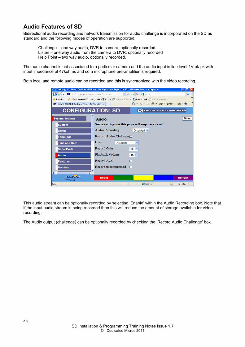
Audio Features of SD Bidirectional audio recording and network transmission for audio challenge is incorporated on the SD as standard and the following modes of operation are supported:
Challenge – one way audio, DVR to camera, optionally recordedListen – one way audio from the camera to DVR, optionally recordedHelp Point – two way audio, optionally recorded.
The audio channel is not associated to a particular camera and the audio input is line level 1V pk-pk with input impedance of 47kohms and so a microphone pre-amplifier is required.
Both local and remote audio can be recorded and this is synchronized with the video recording.
This audio stream can be optionally recorded by selecting ‘Enable’ within the Audio Recording box. Note that if the input audio stream is being recorded then this will reduce the amount of storage available for video recording.
The Audio output (challenge) can be optionally recorded by checking the ‘Record Audio Challenge’ box.
44SD Installation & Programming Training Notes Issue 1.7
© Dedicated Micros 2011

Displaying and Recording Text DataData can be recorded alongside video information. This provides a powerful solution, particularly in retail surveillance systems to make recording more intelligent
How the data is displayed is set up on the Text In Image page. This page needs to be activated before it can be accessed. To do this tick the ‘Text in Images’ box within the ‘Features’ page and select ‘save’. See example below:
Once saved, navigate to the ‘Text’ menu item then the 'Text In Image' web page:
Set the lines and number of characters per line to suit the data from the POS equipmentetc.
Channel defines which camera the data should be associated with and recordedalongside.
SD Installation & Programming Training Notes Issue 1.7© Dedicated Micros 2011
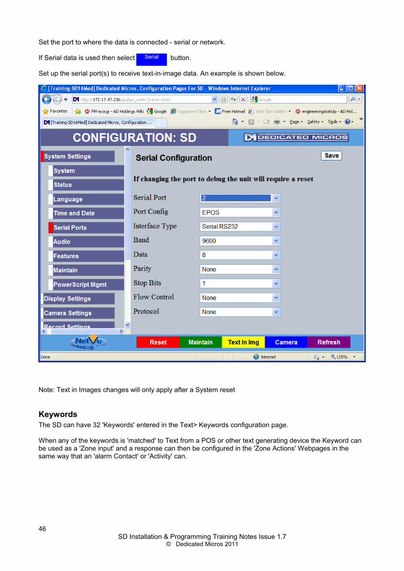
Set the port to where the data is connected - serial or network.
If Serial data is used then select button.
Set up the serial port(s) to receive text-in-image data. An example is shown below.
Note: Text in Images changes will only apply after a System reset
KeywordsThe SD can have 32 'Keywords' entered in the Text> Keywords configuration page.
When any of the keywords is 'matched' to Text from a POS or other text generating device the Keyword can be used as a 'Zone input' and a response can then be configured in the 'Zone Actions' Webpages in the same way that an 'alarm Contact' or 'Activity' can.
46SD Installation & Programming Training Notes Issue 1.7
© Dedicated Micros 2011
Serial


![Applesoft ][ Basic Programming Reference Manual](https://static.fdocuments.in/doc/165x107/543e36e0b1af9f272b8b4827/applesoft-basic-programming-reference-manual.jpg)


