SD-1.5.4-Bulbous Bow · PDF fileBulbous Bow Design and Construction ... of the bulb and the...
27
1 2. Bulbous Bow Design and Construction Ship Design I Manuel Ventura MSc in Marine Engineering and Naval Architecture Bulbous Bow 2 Historical Origin • The bulbous bow was originated in the bow ram (esporão), a structure of military nature utilized in war ships on the end of the XIXth century, beginning of the XXth century.
-
Upload
phungkhanh -
Category
Documents
-
view
245 -
download
4
Transcript of SD-1.5.4-Bulbous Bow · PDF fileBulbous Bow Design and Construction ... of the bulb and the...

1
2. Bulbous Bow Design and Construction
Ship Design I
Manuel Ventura
MSc in Marine Engineering and Naval Architecture
Bulbous Bow 2
Historical Origin
• The bulbous bow was originated in the bow ram (esporão), a structure of military nature utilized in war ships on the end of the XIXth century, beginning of the XXth century.
2
Bulbous Bow 3
Bulbous Bow
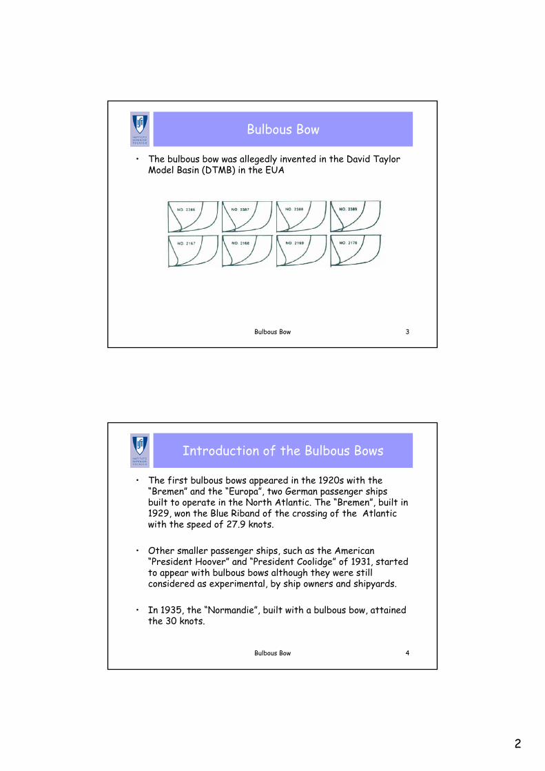
• The bulbous bow was allegedly invented in the David Taylor Model Basin (DTMB) in the EUA
Bulbous Bow 4
Introduction of the Bulbous Bows
• The first bulbous bows appeared in the 1920s with the “Bremen” and the “Europa”, two German passenger ships built to operate in the North Atlantic. The “Bremen”, built in 1929, won the Blue Riband of the crossing of the Atlantic with the speed of 27.9 knots.
• Other smaller passenger ships, such as the American “President Hoover” and “President Coolidge” of 1931, started to appear with bulbous bows although they were still considered as experimental, by ship owners and shipyards.
• In 1935, the “Normandie”, built with a bulbous bow, attained the 30 knots.
3
Bulbous Bow 5
Bulbous Bow in Japan
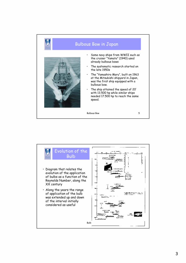
• Some navy ships from WWII such as the cruiser “Yamato” (1940) used already bulbous bows
• The systematic research started on the late 1950s
• The “Yamashiro Maru”, built on 1963 at the Mitsubishi shipyard in Japan, was the first ship equipped with a bulbous bow.
• The ship attained the speed of 20’with 13.500 hp while similar ships needed 17.500 hp to reach the same speed.
Bulbous Bow 6
Evolution of the Bulb
• Diagram that relates the evolution of the application of bulbs as a function of the Reynolds Number, along the XX century
• Along the years the range of application of the bulb was extended up and down of the interval initially considered as useful
4
Bulbous Bow 7
Systems of Waves from the Ship
• There are two types of waves generated by ships:– Divergent Waves – which
are originated at the sides of the ship and have crests inclined in relation to the symmetry plane of the ship
– Transverse Waves – which are originated at the sides fwd and aft (amuras) and have crests perpendicular to the symmetry plane of the ship
• These wave systems are generated both forward and aft• The interference between these wave systems originates the
characteristic bumps and hollows, as a function of the ratio (Vs/Lwl) of the ship.
Bulbous Bow 8
Wave Resistance
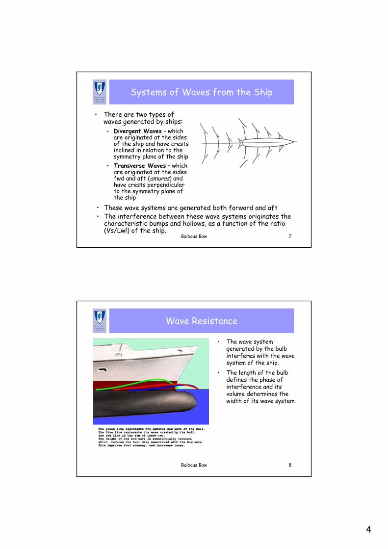
• The wave system generated by the bulb interferes with the wave system of the ship.
• The length of the bulb defines the phase of interference and its volume determines the width of its wave system.
5
Bulbous Bow 9
Usage of the Bulb
• The bulbous bow, by changing the entrance angles of the waterlines and the volume distribution, represents an effective mean of reducing the wave resistance
• Some authors (Wigley) limit the usefulness of the bulb to the interval0.238 ≤ Fn ≤ 0.563
• The bulb shape must be adjusted to the design conditions: – Generally at low speeds the effect of the bulb is negative. When the
Froude Number (FN) increases, its effect becomes positive and increases up to a maximum value.
– From this point upwards, when the FN tends to the infinity, the effect of the bulb tends to zero.
Bulbous Bow 10
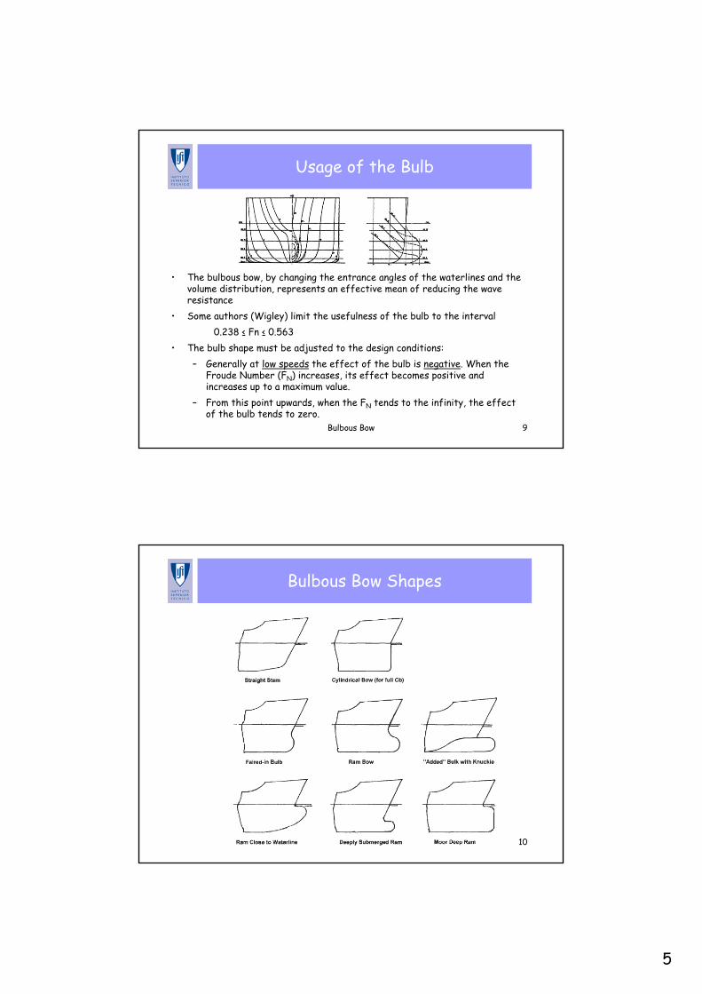
Bulbous Bow Shapes
6
Bulbous Bow 11
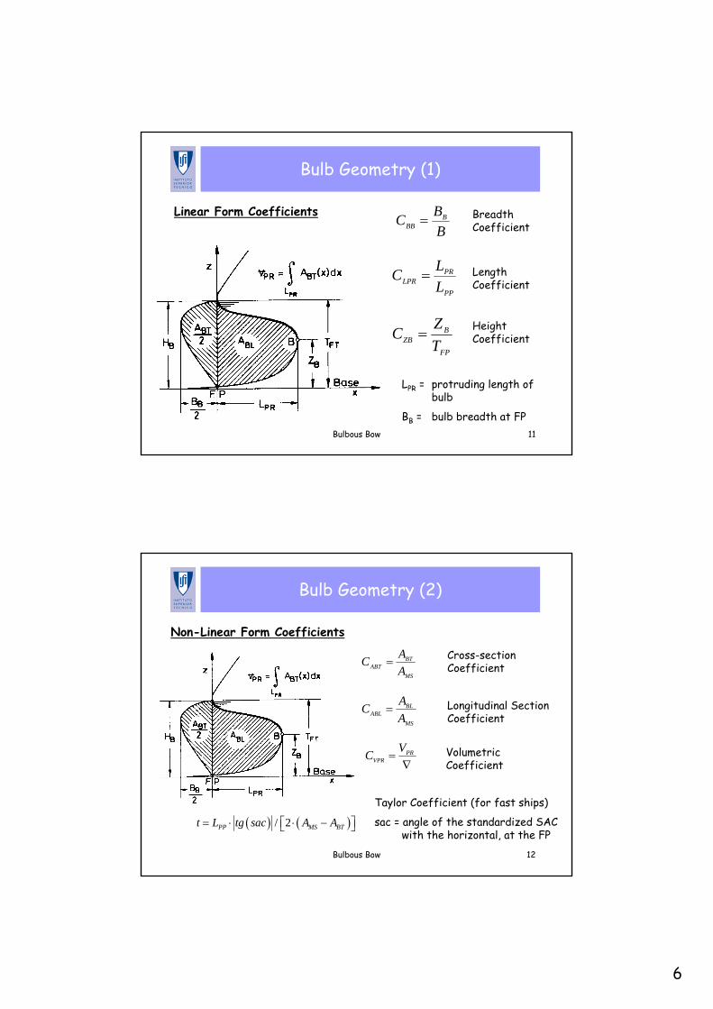
Bulb Geometry (1)
Linear Form CoefficientsBBC B
BB =
PP
PRLPR L
LC =
FP
BZB T
ZC =
Breadth Coefficient
Length Coefficient
Height Coefficient
LPR = protruding length of bulb
BB = bulb breadth at FP
Bulbous Bow 12
Bulb Geometry (2)
Non-Linear Form Coefficients
MS
BTABT A
AC =
MS
BLABL A
AC =
∇= PR
VPR
VC
( ) ( )/ 2PP MS BTt L tg sac A A= ⋅ ⋅ −⎡ ⎤⎣ ⎦
Cross-section Coefficient
Longitudinal Section Coefficient
Volumetric Coefficient
Taylor Coefficient (for fast ships)
sac = angle of the standardized SAC with the horizontal, at the FP
7
Bulbous Bow 13
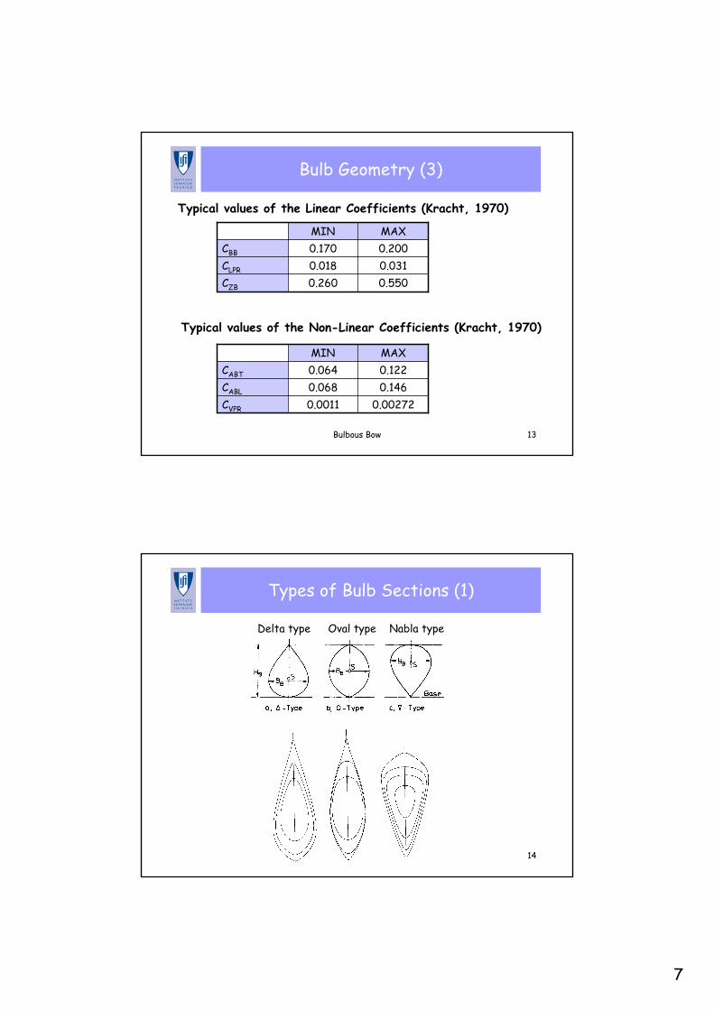
Bulb Geometry (3)
Typical values of the Linear Coefficients (Kracht, 1970)
Typical values of the Non-Linear Coefficients (Kracht, 1970)
0.5500.260CZB
0.0310.018CLPR
0.2000.170CBB
MAXMIN
0.002720.0011CVPR
0.1460.068CABL
0.1220.064CABT
MAXMIN
Bulbous Bow 14
Types of Bulb Sections (1)
Delta type Nabla typeOval type
8
Bulbous Bow 15
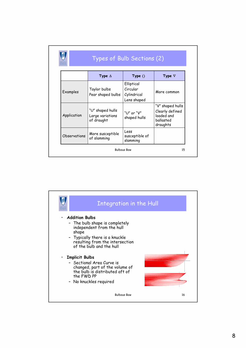
Types of Bulb Sections (2)
Less susceptible of slamming
More susceptible of slammingObservations
“V” shaped hullsClearly defined loaded and ballasted draughts
“U” or “V”shaped hulls
“U” shaped hullsLarge variations of draught
Application
More common
EllipticalCircularCylindricalLens shaped
Taylor bulbsPear shaped bulbs
Examples
Type ∇Type ()Type Δ
Bulbous Bow 16
Integration in the Hull
• Addition Bulbs– The bulb shape is completely
independent from the hull shape
– Typically there is a knuckle resulting from the intersection of the bulb and the hull
• Implicit Bulbs– Sectional Area Curve is
changed, part of the volume of the bulb is distributed aft of the FWD PP
– No knuckles required
9
Bulbous Bow 17
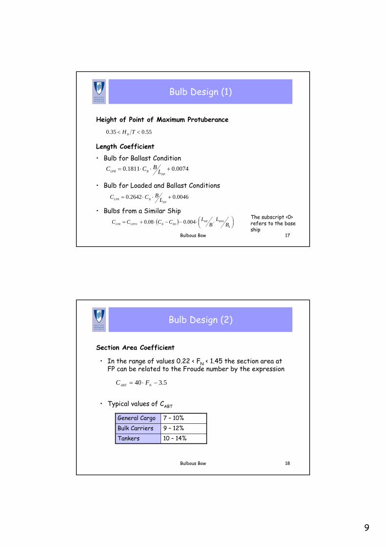
Bulb Design (1)
55.035.0 << THB
0074.01811.0 +⋅⋅=PP
BLPR LBCC
0046.02642.0 +⋅⋅=PP
BLPR LBCC
( ) ⎟⎠⎞⎜
⎝⎛ ⋅⋅−−⋅+=
0
000 004.008.0 B
LB
LCCCC PPPPBBLPPLPR
Height of Point of Maximum Protuberance
Length Coefficient
• Bulb for Ballast Condition
• Bulb for Loaded and Ballast Conditions
• Bulbs from a Similar ShipThe subscript <0> refers to the base ship
Bulbous Bow 18
Bulb Design (2)
Section Area Coefficient
5.340 −⋅= NABT FC
10 – 14%Tankers9 – 12%Bulk Carriers7 – 10%General Cargo
• Typical values of CABT
• In the range of values 0.22 < FN < 1.45 the section area at FP can be related to the Froude number by the expression
10
Bulbous Bow 19
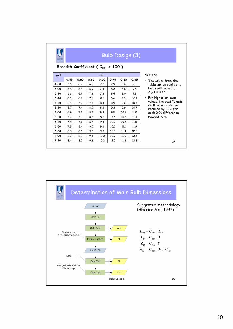
Bulb Design (3)
Breadth Coefficient ( CBB x 100 )
12.811.811.010.29.68.98.47.2012.511.610.710.09.48.88.27.0012.211.410.59.89.28.68.06.8011.911.110.39.69.08.47.86.6011.610.810.09.38.78.17.56.4011.310.59.79.18.57.97.26.2011.010.29.58.88.27.66.96.0010.79.99.28.68.07.46.75.8010.49.68.98.47.87.26.55.6010.19.38.68.17.66.96.35.409.89.08.47.87.36.76.15.209.58.88.27.46.96.45.85.009.38.67.97.26.66.25.64.800.850.800.750.700.650.600.55
CBLPP/B NOTES:
• The values from the table can be applied to bulbs with approx. ZB/T = 0.45.
• For higher or lower values, the coefficients shall be increased or reduced by 0.1% for each 0.01 difference, respectively.
Bulbous Bow 20
Determination of Main Bulb Dimensions
Suggested methodology (Alvarino & al, 1997)
Vs, Lwl
Calc Fn
Calc Cabt Abt
Lpp/B, Cb
Estimate (Zb/T)
Calc Cbb Bb
Calc Clpr Lpr
Zb
Similar ships0.35 < (Zb/T) < 0.55
Table
Design load conditionSimilar ship
PR LPR PP
B BB
B HB
BT BB M
L C LB C BZ C T
A C B T C
= ⋅= ⋅= ⋅= ⋅ ⋅ ⋅
11
Bulbous Bow 21
Advantages of the Bulbous Bow (1)
• The bulbous bow has several important advantages and does not present relevant disadvantages:– Reduces the bow wave, due to the wave generated by the bulb
itself, making the ship more efficient in terms of energy– Increases the ship’s waterline length, slightly increasing the
ship speed, reducing the installed power requirements and so the fuel oil consumption
Bulbous Bow 22
Advantages of the Bulbous Bow (2)
– Works as a robust “bumper" in the event of a collision – Allows the installation of the bow thrusters at a foremost
position, making it more efficient– Allows a larger reserve of flotation or a larger ballast capacity
forward– Reduces the pitch movement (cabeceio)
12
Bulbous Bow 23
Aspects of the Initial Bulb Design
• The bulb shall never emerge completely. The point at the forward extremity shall be at the level of the waterline
• Distribution of the bulb volume– Too much immersion doe not produce any effect– Volume concentrated longitudinally near the free surface
increases the effect of interference in waves
• The waterlines at the bulb extremity should have a thin shape but not circular, to avoid the flow separation
• The bulb is advantageous in ice navigation – the ice blocks slide along the bulb with their “wet” side, which has a lower friction coefficient
Use of CFD on Bulb Design and Analysis
13
Bulbous Bow 25
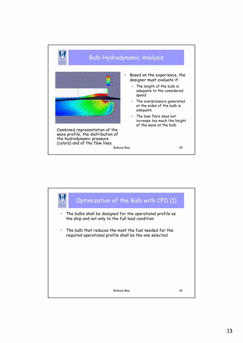
Bulb Hydrodynamic Analysis
• Based on the experience, the designer must evaluate if:– The length of the bulb is
adequate to the considered speed
– The overpressure generated at the sides of the bulb is adequate
– The bow flare does not increase too much the height of the wave at the bulb
Combined representation of the wave profile, the distribution of the hydrodynamic pressure (colors) and of the flow lines
Bulbous Bow 26
Optimization of the Bulb with CFD (1)
• The bulbs shall be designed for the operational profile osthe ship and not only to the full load condition
• The bulb that reduces the most the fuel needed for the required operational profile shall be the one selected
14
Bulbous Bow 27
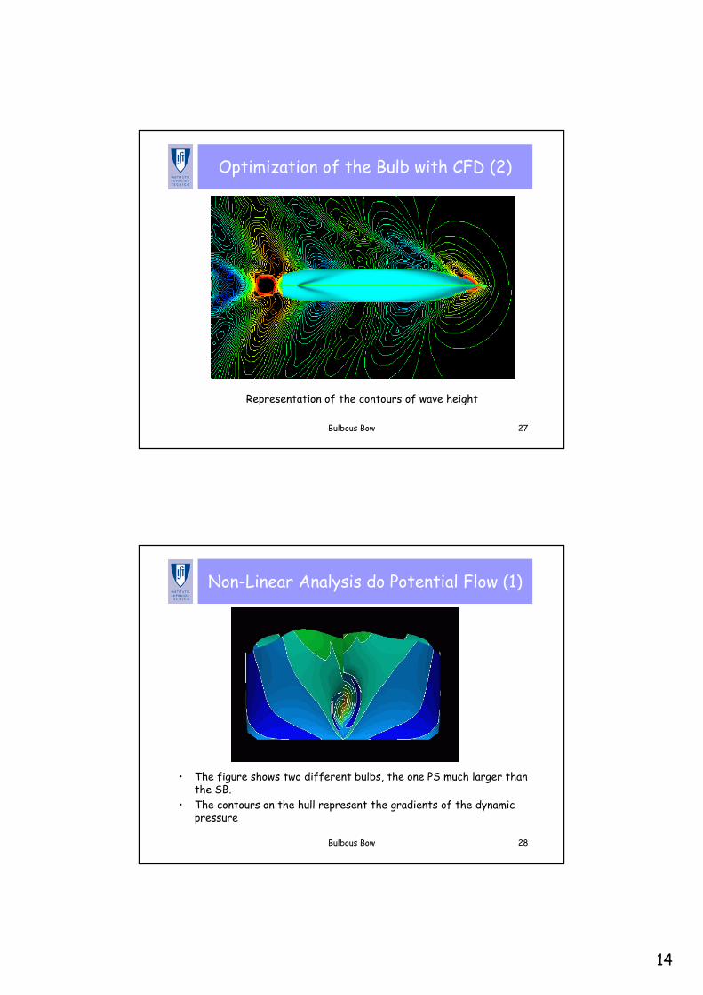
Optimization of the Bulb with CFD (2)
Representation of the contours of wave height
Bulbous Bow 28
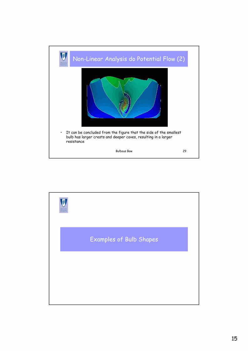
Non-Linear Analysis do Potential Flow (1)
• The figure shows two different bulbs, the one PS much larger than the SB.
• The contours on the hull represent the gradients of the dynamic pressure
15
Bulbous Bow 29
Non-Linear Analysis do Potential Flow (2)
• It can be concluded from the figure that the side of the smallest bulb has larger crests and deeper caves, resulting in a larger resistance
Examples of Bulb Shapes
16
Bulbous Bow 31
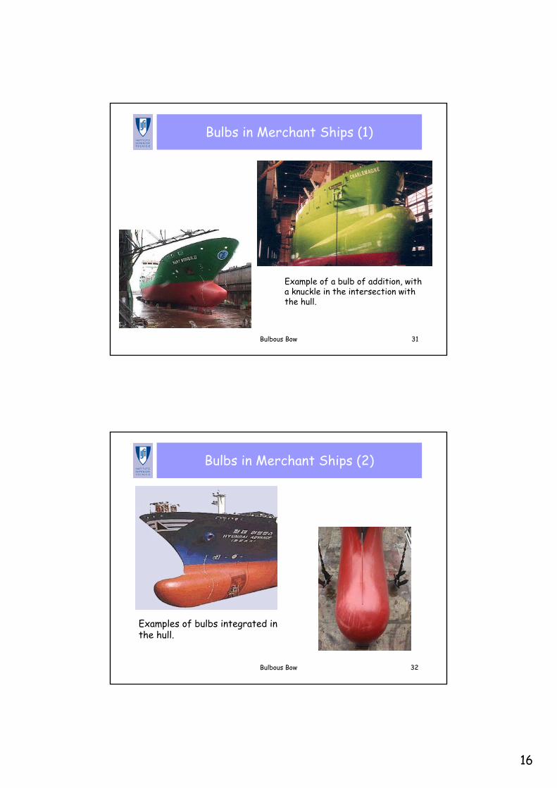
Bulbs in Merchant Ships (1)
Example of a bulb of addition, with a knuckle in the intersection with the hull.
Bulbous Bow 32
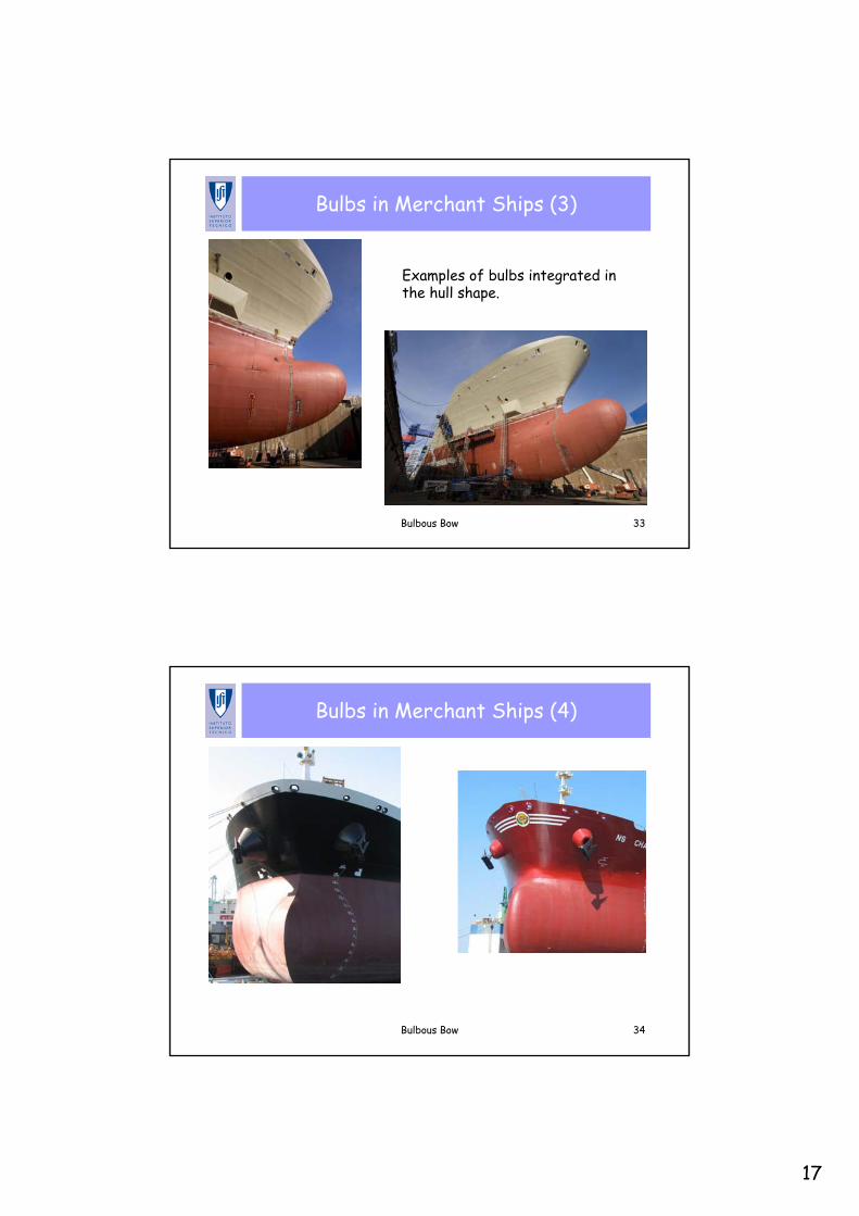
Bulbs in Merchant Ships (2)
Examples of bulbs integrated in the hull.
17
Bulbous Bow 33
Bulbs in Merchant Ships (3)
Examples of bulbs integrated in the hull shape.
Bulbous Bow 34
Bulbs in Merchant Ships (4)
18
Bulbous Bow 35
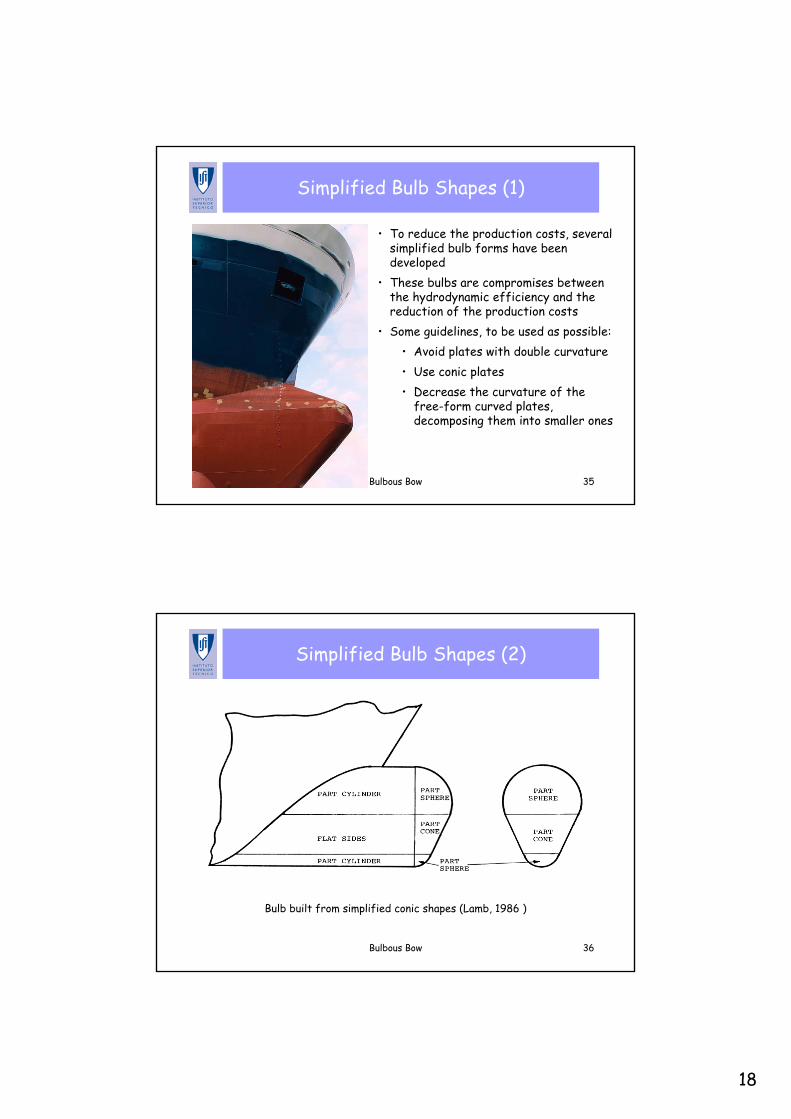
Simplified Bulb Shapes (1)
• To reduce the production costs, several simplified bulb forms have been developed
• These bulbs are compromises between the hydrodynamic efficiency and the reduction of the production costs
• Some guidelines, to be used as possible:• Avoid plates with double curvature• Use conic plates• Decrease the curvature of the
free-form curved plates, decomposing them into smaller ones
Bulbous Bow 36
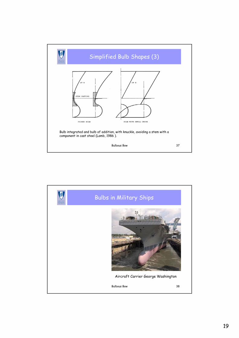
Simplified Bulb Shapes (2)
Bulb built from simplified conic shapes (Lamb, 1986 )
19
Bulbous Bow 37
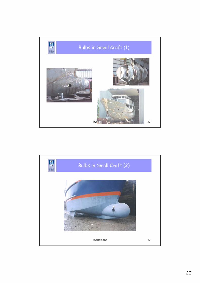
Simplified Bulb Shapes (3)
Bulb integrated and bulb of addition, with knuckle, avoiding a stem with a component in cast steel (Lamb, 1986 ).
Bulbous Bow 38
Bulbs in Military Ships
Aircraft Carrier George Washington
20
Bulbous Bow 39
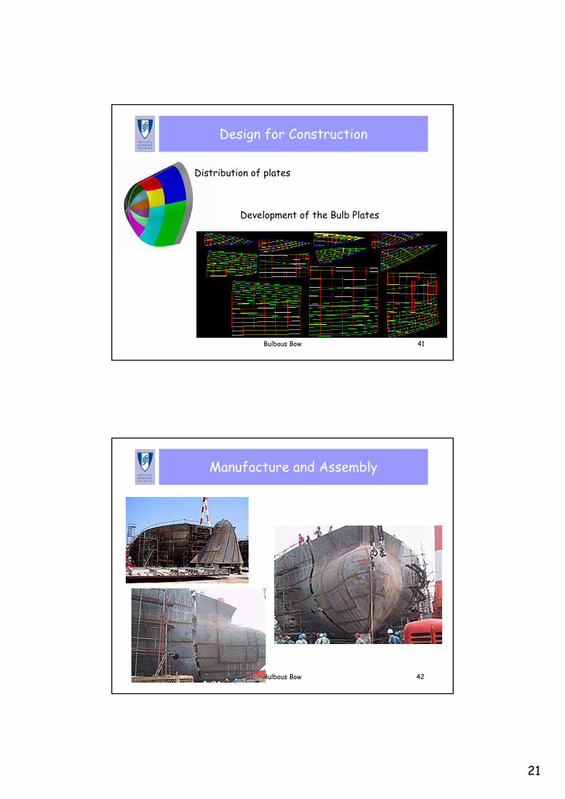
Bulbs in Small Craft (1)
Bulbous Bow 40
Bulbs in Small Craft (2)
21
Bulbous Bow 41
Design for Construction
Development of the Bulb Plates
Distribution of plates
Bulbous Bow 42
Manufacture and Assembly
22
Bulbous Bow 43
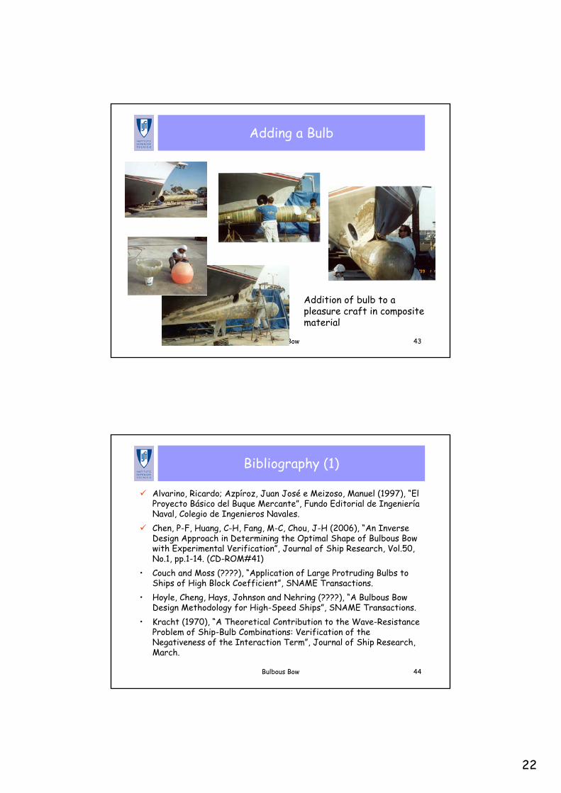
Adding a Bulb
Addition of bulb to a pleasure craft in composite material
Bulbous Bow 44
Bibliography (1)
Alvarino, Ricardo; Azpíroz, Juan José e Meizoso, Manuel (1997), “El Proyecto Básico del Buque Mercante”, Fundo Editorial de IngenieríaNaval, Colegio de Ingenieros Navales.Chen, P-F, Huang, C-H, Fang, M-C, Chou, J-H (2006), “An Inverse Design Approach in Determining the Optimal Shape of Bulbous Bow with Experimental Verification”, Journal of Ship Research, Vol.50, No.1, pp.1-14. (CD-ROM#41)
• Couch and Moss (????), “Application of Large Protruding Bulbs to Ships of High Block Coefficient”, SNAME Transactions.
• Hoyle, Cheng, Hays, Johnson and Nehring (????), “A Bulbous Bow Design Methodology for High-Speed Ships”, SNAME Transactions.
• Kracht (1970), “A Theoretical Contribution to the Wave-Resistance Problem of Ship-Bulb Combinations: Verification of the Negativeness of the Interaction Term”, Journal of Ship Research, March.

23
Bulbous Bow 45
Bibliography (2)
Kracht (1978), “Design of Bulbous Bows”, SNAME Transactions. Kyriazis, Georgios (1996), “Bulbous Bow Design Optimization for Fast Ships”, MSc Thesis, MIT. (CD-ROM#70)
• Lamb, Thomas (1986), “Engineering for Ship Production”, SNAME.• Lee, K.J. and Sarath, E.S. (2005), "Optimized Design of Hull Form
and Bulbous Bow for ULCS", Proceedings of The Fifteenth (2005) International Offshore and Polar Engineering Conference, Seoul, Korea.Pérez, Francisco; Suárez, José A.; Clemente, Juan A. and Souto, Antonio (2007), "Geometric Modelling of Bulbous Bows with the use of Non-Uniform Rational B-spline Surfaces", Journal of Marine Science and Technology, Vol.12, Number 2, June 2007, pp. 83-94.Sharma, R. and Sha, O.P. (2005), "Practical Hydrodynamic Design of Bulbous Bows for Ships", Naval Engineers Journal, Vol.117, No.1,pp.57-76.
Bulbous Bow 46
Bibliography (3)
• Smith and Salvesen (1970), “Comparison of Ship-Motion Theory and Experiment for Destroyer with Large Bulb”, Journal of Ship Research, March 1970.
• Yim, B. (1974), “A Simple Design Theory and Method for Bulbous Bows of Ships”, Journal of Ship Research, Vol.18, No.3, pp.141-152.
24
Annex A. Some Bulb Design Patents
Bulbous Bow 48
Conical Bulbous Bow (1)
• A novel bulbous bow for bulk carriers comprises a conical bulb with a faired nose, with the axis of the cone substantially parallel to the longitudinal axis of the ship.
• In a preferred embodiment the cone is a right circular cone and the faired nose is substantially a hemisphere. More particularly, the included angle of the cone is in the range of five to twentydegrees.
• Although the cone could be faired into the hull, preferably it is not. • The longitudinal centerline of the bulb is located between 45 and
60 percent of the design draft below the design waterline. • The preferred extension of the bulb, beyond the forward
perpendicular, is proportional to the square of design speed with the proportionality factor in the range of 0.015 to 0.04 and preferably 0.035.
United States Patent 3946687 (1976)
25
Bulbous Bow 49
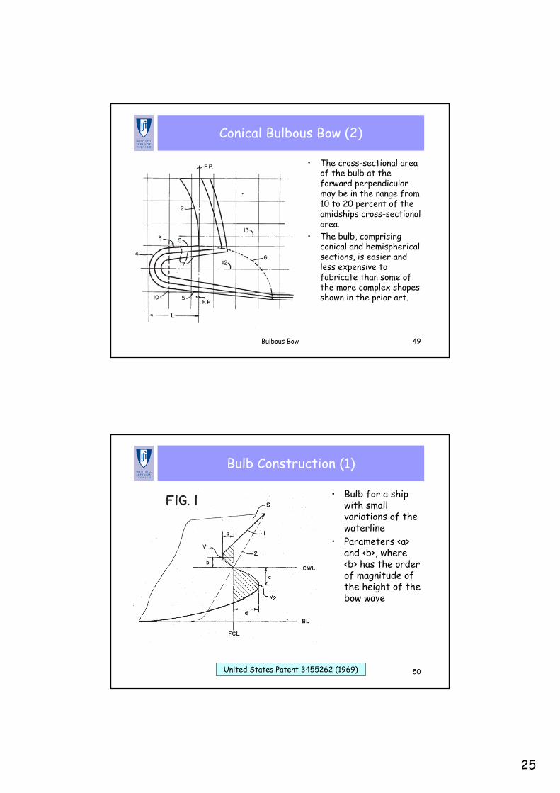
Conical Bulbous Bow (2)
• The cross-sectional area of the bulb at the forward perpendicular may be in the range from 10 to 20 percent of the amidships cross-sectional area.
• The bulb, comprising conical and hemispherical sections, is easier and less expensive to fabricate than some of the more complex shapes shown in the prior art.
Bulbous Bow 50
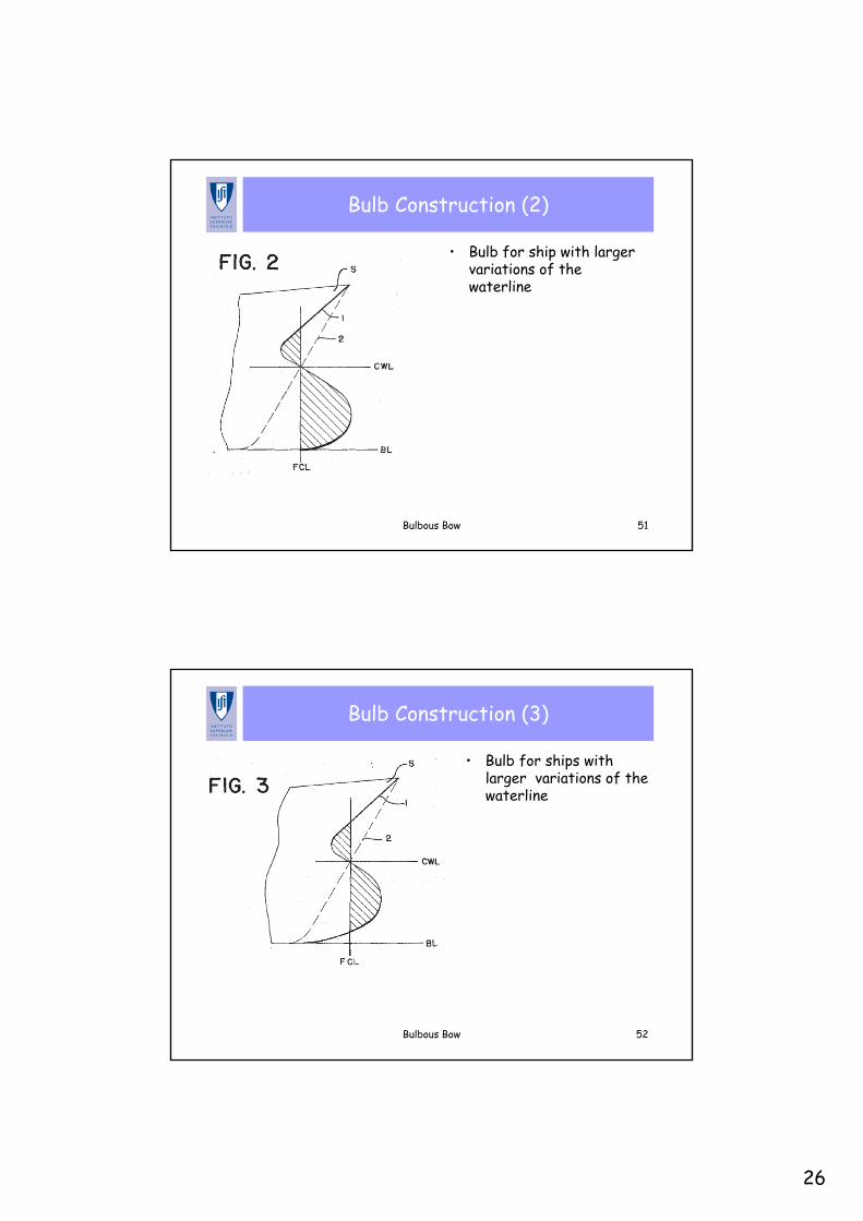
Bulb Construction (1)
• Bulb for a ship with small variations of the waterline
• Parameters <a> and <b>, where <b> has the order of magnitude of the height of the bow wave
United States Patent 3455262 (1969)
26
Bulbous Bow 51
Bulb Construction (2)
• Bulb for ship with larger variations of the waterline
Bulbous Bow 52
Bulb Construction (3)
• Bulb for ships with larger variations of the waterline
27
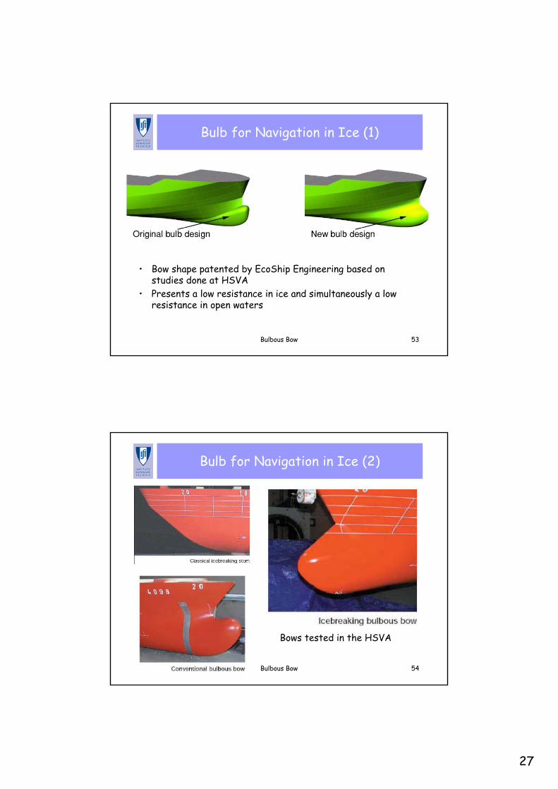
Bulbous Bow 53
Bulb for Navigation in Ice (1)
• Bow shape patented by EcoShip Engineering based on studies done at HSVA
• Presents a low resistance in ice and simultaneously a low resistance in open waters
Bulbous Bow 54
Bulb for Navigation in Ice (2)
Bows tested in the HSVA