SD 150 USER MANUAL - ancar-files.com · DENTAL UNIT - QS4-366-02 / SD 150. USER MANUAL. 2. Thank...
31
SD 150 USER MANUAL
Transcript of SD 150 USER MANUAL - ancar-files.com · DENTAL UNIT - QS4-366-02 / SD 150. USER MANUAL. 2. Thank...

SD 150USER MANUAL


ISO 9001 ISO 13485 109037-AQ-IBE 112630-AQ-IBE
EC Declaration of Conformity (Directive 93/42/EEC)
Manufacturer’s Name ANTONI CARLES, S.A. With manufacturing and putting together of medical devices license number 2509-PS granted by the Health Authorities of Spain.
Name of device: Type or Model: Dental Unit GMDNS Code: 34991 Sd-150
Device Class according to the intended use and the criteria of Annex IX of the Directive: Class IIa (rule 11)
Scope of Application: All (including parts and accessories) Power Supply: 220-240 V ~ / 50-60 Hz Electric Classification: Type B This Declaration is based on Certificates issued by DNV:
#78388-2010-CE-IBE-NA according to annex V, DIR 93/42/EEC. #109037-2012-AQ-IBE-ENAC according to ISO 9001:2008. #112630-2012-AQ-IBE-NA according to ISO 13485:2003.
Notified Body:
0434 DNV (Det Norske Veritas) – Region Norge As.
We, the undersigned, under our sole responsibility, certify and declare that the medical devices specified above are in conformity with the essential requirements, which are applicable to them, of RD 1591/09, transposition to the Spanish law of the directive 93/42/EC as amended by the directive 2007/47/EC. We also declare that we comply with the design and construction requirements of the following standards:
EN 1640 :2009 Dentistry. Medical devices for dentistry. Equipment. EN ISO 7494-1:2011 Dentistry. Dental Units. Part 1. General requirements and test methods. EN ISO 7494-2:2003 Dentistry. Dental Units. Part 2. Water and air supply. EN 60601-1:2006 + AC :2010
Medical Electrical Equipment. General requirement for safety.
EN 60601-1-2:2007 + AC :2010
Medical Electrical Equipment. General requirement for safety. Electromagnetic Compatibility – Requirements and tests.
EN ISO 14971 :2012 Medical Devices. Application of Risk Management to Medical Devices.
Authorized Signatory Stamp, Date
Josep Álvarez Antoni Carles Bosch November 29, 2013 Regulatory & Safety Officer General Manager
Antoni Carles, S.A. Volta dels Garrofers, 41-42 Pol. Ind. Els Garrofers 08340-Vilassar de Mar (Barcelona-SPAIN)
T. (34) 93 754 07 97 F. (34) 93 759 26 04 [email protected] www.ancar-dental.com
ANTONI CARLES, S.A. Pol. Ind. “Els Garrofers
C/Volta dels Garrofers, 41-42. 08340 VILASSAR DE MAR
BARCELONA-SPAIN


USER MANUAL DENTAL UNIT - QS4-366-02 / SD 150
1
PAGE
1.- PRECAUTIONS 2
2.- GUARANTEE 2
3.- IDENTIFICATION 3
4.- PRECAUTIONS 3
5.- CLAUSES 4
6.- TECHNICAL FEATURES 5
6.1.- Chair 5
6.2.- Dental Unit 5
7.- DIMENSIONS AND TRANSPORTATION 6
8.- DESCRIPTION 7
8.1.- Circuit box 8
8.2.- Pneumatic pedal 9
8.3.- Instrument tray 10
8.4.- Main keypad 12
8.5.- Water Cabinet 13
8.6.- Cannula support 14
8.7.- Auxiliary keypad 15
8.8.- Headrest 16
8.9.- Optional armrest 16
9.- SAFETY MOVEMENTS 17
10.- CLEANING AND STERILISING 17
11.- TECHNICAL DATA 18
APPENDIX 1. CLEANING AND DISINFECTING OF CATTANI GLASS, CANNULASAND BASIN 19
APPENDIX 2. METASYS AMALGAM SEPARATOR 20
APPENDIX 3. CLEANING AND DISINFECTING OTHER PARTS OF THE UNIT 21
APPENDIX 4. DURR VSA300 SUCTION SYSTEM 22
APPENDIX 5. MINILIGHT SYRINGE (LUZZANI)
APPENDIX 6. SAFETY OBSERVATIONS 25
TABLE OF CONTENTS

USER MANUALDENTAL UNIT - QS4-366-02 / SD 150
2
Thank you for purchasing the SD-150 dental unit.This instruction manual contains information on the dental unit, including its configuration and maintenance.
0434 This symbol means the unit is certified under Directive 93/42/EEC by the DNV
Notes This symbol means CAUTION, PRECAUTION
Before starting-up the unit you must have read and fully understood the user manual.
Keep this manual in a safe place for future reference, for as long as you use the equipment.
Follow all safety standards.
It is the user’s responsibility to keep the unit clean, disinfected and in perfect working order.
1.- PRECAUTIONSThis equipment may only be moved by authorised technicians.The unit must be installed in an environment with controlled conditions, including temperature (+10˚C to +40˚C), humidity (30-75 %) and atmospheric pressure (700 a 1060 hPa), free from dust and condensation and protected from direct sunlight.The electrical circuit at the premises where the unit is to be installed must satisfy the provisions in standard IEC 601.1 regarding protection against electric shock for class I equipment.Antoni Carles, S.A.reserves the right to make any improvements or modifications to the dental unit without prior warning.The unit must be used in accordance with the use instructions.Under Directive 93/42/EEC, the dental unit and dental chair manufactured by Antoni Carles, S.A.are class IIa equipment. It is absolutely prohibited to install any class IIb or III dental instrument, e.g. surgical lasers, electronic scalpels, X-rays or electric cauterizers. Only class I or IIa equipment may be installed, in compliance with the provisions in the aforementioned Directive and standardised regulations EN60601-1, EN60601-1-2.
2.- GUARANTEEThe device comes with a Certificate of Guarantee. If you do not receive this, ask your dealer directly. The Certificate of Guarantee must be completed and returned to the manufacturer (Antoni Carles, S.A.) within 8 days of delivery of the device.The guarantee is only valid if the device has been used correctly and installed by an authorised technician.Moreover, to comply with Health Equipment traceability in accordance with Directive 93/42/EEC, you must also return the installation form.
USER MANUAL DENTAL UNIT - QS4-366-02 / SD 150
3
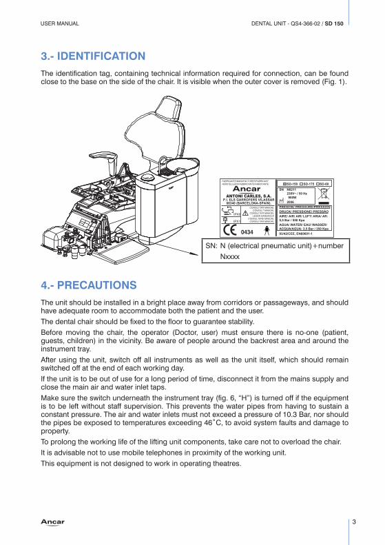
3.- IDENTIFICATIONThe identification tag, containing technical information required for connection, can be found close to the base on the side of the chair. It is visible when the outer cover is removed (Fig. 1).
4.- PRECAUTIONSThe unit should be installed in a bright place away from corridors or passageways, and should have adequate room to accommodate both the patient and the user.The dental chair should be fixed to the floor to guarantee stability.Before moving the chair, the operator (Doctor, user) must ensure there is no-one (patient, guests, children) in the vicinity. Be aware of people around the backrest area and around the instrument tray.After using the unit, switch off all instruments as well as the unit itself, which should remain switched off at the end of each working day.If the unit is to be out of use for a long period of time, disconnect it from the mains supply and close the main air and water inlet taps. Make sure the switch underneath the instrument tray (fig. 6, “H”) is turned off if the equipment is to be left without staff supervision. This prevents the water pipes from having to sustain a constant pressure. The air and water inlets must not exceed a pressure of 10.3 Bar, nor should the pipes be exposed to temperatures exceeding 46˚C, to avoid system faults and damage to property.To prolong the working life of the lifting unit components, take care not to overload the chair. It is advisable not to use mobile telephones in proximity of the working unit.This equipment is not designed to work in operating theatres.
0434
FABRICANTE/MANUFACTURER/FABRICANTHERSTELLERS/FABBRICANTE/FABRICANTE
ANTONI CARLES, S.A.P.I. ELS GARROFERS VILASSAR
08340 (BARCELONA-SPAIN).CONSULTAR MANUAL
CONSULT MANUALCONSULTER MANUEL
LESEN HANDBUCHCONSULTARE MANUAL
CONSULTAR MANUAL
SD-150 SD-175 SD-60
SN N0211230V~ / 50 Hz900W
2006PRESION/ PRESSURE/PRESSIONDRUCK/ PRESSIONE/ PRESSÂO AIRE/ AIR/ AIR/ LUFT/ ARIA/ AR:5,5 Bar / 550 KpaAGUA/ WATER/ EAU/ WASSER/ACQUA/AGUA: 3,5 Bar / 350 Kpa93/42/CEE, EN60601-1
IPX1
IPX0
SN: N (electrical pneumatic unit)+number Nxxxx

USER MANUALDENTAL UNIT - QS4-366-02 / SD 150
4
ENVIRONMENTAL PROTECTIONAll packaging materials are produced in respect for the environment and are fully recyclable: wooden pallets, cardboard, plastic bags and bubble-wrap. Collecting used materials helps collection and recycling and reduces waste material.Antoni Carles, S.A. is obliged to satisfy the objectives set by Community Directives 2002/95/EC and 2002/96/EC.
This symbol is only applicable for member countries of the European Union.In order to avoid potential negative consequences for the environment or human health, this equipment should be disposed of (i) in EU member countries – in accordance with the WEEE (Waste Electrical and Electronic Equipment) Directive, and (ii) for all other countries, in accordance with local provisions and recycling laws.
EMCThe Sd-150 dental unit conforms to the basic requirements of Directive 93/42/EEC concerning medical devices, and complies with the design and construction requirements contained in Standard EN60601-1-2 regarding the safety of Electromagnetic Compatibility and Electrical Medical Equipment, causing no electromagnetic disturbances and complying with immunity standards.
5.- CLAUSESAntoni Carles, S.A. will not assume responsibility for damages caused by fire, natural disasters, third party activities or other accidents caused by operator negligence or misuse, or from using the equipment under unusual conditions. Antoni Carles, S.A. will not assume responsibility for damages deriving from the improper use of equipment, causing a loss of business or loss of earnings.Antoni Carles, S.A. will not assume responsibility for results of diagnoses made by a doctor using this equipment.

USER MANUAL DENTAL UNIT - QS4-366-02 / SD 150
5
6.- TECHNICAL FEATURES
6.1.- ChairErgonomic design for the patient.Dental chair with silent, automatic and highly reliable movement.Microprocessor-controlled movements: - automatic chair return movement. - automatic chair-to-spittoon movement. - 3 programmable chair settings.High quality, hygienic anatomic upholsterySafe movement of the base and backrest of the chair, which is raised upwards until locked in place.Height-adjustable, folding headrest.Includes Trendelenburg position.
6.2.- Dental UnitEasy-maintenance finish.Instrument tray with space to hold 5 instruments and a 14-function control panel. Includes syringe.Optional: adjustable electric micromotor. Reversible rotation. Optional light control panel for instruments with light fitting (micromotor, turbine, ultrasound). 75° rotational water unit, spittoon with automatic cup filler and basin washer system. Optional fitting of different suction systems and amalgam systems.Pneumatically braked arm movements with auxiliary instrument tray.Cannula and circuit boxes located in the front of the chair.Control panel on instrument tray and cannula support.The unit is designed to hide all tubes or cables out of sight, except for those on the instrument tray.The unit conforms to the basic requirements applied by Directive 93/42/EEC on medical devices, to the design and construction requirements contained in Standards EN60601-1 and EN60601-1-2 regarding the safety of Electromagnetic Compatibility and Electrical Medical Equipment, and to ISO standard 14971, a Risk Management analysis1.

USER MANUALDENTAL UNIT - QS4-366-02 / SD 150
6
7.- DIMENSIONS AND TRANSPORTATIONThe dental unit is suitably packaged and protected. The package includes the dental unit secured to a pallet, with a further two cases containing the water unit and colibri forceps system (Fig. 2).It is essential that none of the boxes are knocked when in transit, and under no circumstances must they fall to the floor. Great care should be taken when moving the equipment; we recommend it be transported by technicians authorised by Antoni Carles, S.A.Before assembling the unit, a technician, along with yourself and the authorised member of staff on-site should determine its best location with regard to comfort and ergonomics.
Should you have to move a pre-assembled unit, fit the chair first with the seat at its lowest position and the back raised, making sure the water unit and instrument tray are fully retracted over the chair at all times, keeping the unit as solid as possible.
Once in position, remember to secure the chair to the floor.
2990
MIN:
1130
/ MAX
: 1540
MAX:
840
MIN:
430
950
600
Fig. 2 Dimensions

USER MANUAL DENTAL UNIT - QS4-366-02 / SD 150
7
8.- SD150 DENTAL UNIT DESCRIPTION (Fig. 3)
Fig. 4 Circuit box Page 8Fig. 5 Pneumatic pedal Page 9Fig. 6 Instrument tray Page 11Fig. 7 Main control panel Page 12Fig. 8 Water unit Page 13Fig. 9 Cannula support Page 14Fig. 10 Auxiliary control panel Page 15Fig. 11 Headrest Page 16Fig. 12 Armrest Page 16
Fig. 4Fig. 5
Fig. 6
Fig. 7Fig. 8
Fig. 10Fig. 9
Fig. 11
Fig. 12
Fig. 3

USER MANUALDENTAL UNIT - QS4-366-02 / SD 150
8
8.1.- Circuit boxThe circuit box contains all points for connecting the dental unit to the clinic’s power supply, as well as controls for adjusting the air and water supply. Regulator directional movement conforms to Standard UNE 20128.As indicated in the diagram, the front part of the chair base contains: (Fig. 4) A. General power switch. Up, on; down, off. Pilot light. B. General mains fuse, rating T6.3A/250V, type 5x20mm. Fuses should be replaced by an
authorised technician. C. General compressed air switch. The compressor should be correctly installed to avoid the
build-up of humidity in the air circuit. D. General water switch. Inlet water must be well purified. E. Air inlet pressure control. Fitted with a solid particle filter. Check around once per month.
Clean using pressurised water. F. Water inlet pressure control. Fitted with a solid particle filter. Check around once per
month. Clean using pressurised water. G. Movement panel connection cover. H. Connection panel and transformer cover.
Note: when activating the general power switch (“A”), the connection panel will perform a function test producing an audible beeping sound. If you do not hear this sound, switch off the unit and contact your technical service provider.
G
H
B
A
+ -EF
D C
Fig. 4

USER MANUAL DENTAL UNIT - QS4-366-02 / SD 150
9
8.2.- Pneumatic pedal:INSTALLATION AND USEPedal for adjusting the optional instruments on the instrument tray: Micromotor, turbine. Ultrasound on/off switch.Control the electric micromotor rotation speed, turbine power and pneumatic micromotor by activating the trigger (B); select air only or air and water, using lever-operated spray function (A). The pedal-controlled electric micromotor has a speed control indicator, as it allows very sensitive and progressive movement.Lever-operated chip blower function (A) when the lever (B) is in the return position.It does not control cannula support instruments; only those on the instrument tray.
Optional instrument cleaning turbines and micromotors, removing every last drop of water with an automatic air blower.
Safe movement of all optional instrument tray items: by adjusting the control lever the chair is locked in place, or it can be secured in any position.
PEDAL FUNCTIONS (Fig. 5) A. Chip blower control button/lever. Short-burst air blower. B. Control trigger to activate and adjust the selected instrument while still on the tray. Pressing the trigger (B): air only, no water. Pressing the trigger (B) and lever (A): water and air, spray function. C. Backrest return movement. D. Manual chair recline movement. E. Backrest recline movement. F. Manual chair return movement.
Safety:
To block any button-activated memory, press the control pedal.
When activating the control pedal, all chair movements are blocked.
This pedal can accept as an option the setting to zero automatically. By default, it is not incorporated.
A
B
FC
ED
Fig. 5

USER MANUALDENTAL UNIT - QS4-366-02 / SD 150
10
8.3.- Instrument trayThe instrument tray (Fig. 6), ergonomically designed to facilitate the work of the user, is also fitted with an auxiliary instrument tray (A), a slight inclination of the main keypad (B) to provide easy viewing, and a comfortable chair positioning handle (C). Use the button located on the front (D) to release the pneumatic brake and to adjust the height position.The instrument layout (E) has up to five (1,2,3,4,5) positions which can be pre-configured upon request.Any later modifications must be carried out by an authorised technician.The turbine and both pneumatic and electric micromotors can be situated in 4 work positions.Once their positions are set, the turbine and pneumatic micromotor are interchangeable. - Silicon instrument support (E), protects instruments from knocks. Can be sterilised and
easily removed for autoclave sterilisation. - Auxiliary instrument tray installation. - The smooth, non-porous, rounded-edge tray allows easy access for rapid cleaning and
disinfecting. - Arm levelling (authorised technician only) - Arm brake adjustment (authorised technician only) - Overhead poles protect the instrument if dropped. - Turbine lamp with pedal-free operation. - Instrument tray rotation: 125°. 30cm vertical movement.
LOWER PART OF TRAY:water controllers are located alongside each optional instrument (installed upon request).E (1, 2, 3, 4)Water controllers are aligned with each optional instrument, installed upon request (micromotor, light micromotor, turbine, light turbine or ultrasound, respectively).F Ultrasound power setting.G Micromotor directional selector.
Should the turbine or micromotor spray function not work, or if there is no water in the ultrasound, check that these regulators are fully opened by turning them anticlockwise.
H General air and water switch
This switch must be turned off if the unit is left unsupervised. Deactivating this switch prevents water pipes from being subjected to constant pressure through the intake.
J Electric micromotor work mode selector: normal or reduced mode. This allows the user to work at low speeds within the range of approx. 0 to 3,000 rpm.K Removable tank for the micromotor and turbine lubrication oil return filter. Check periodically.

USER MANUAL DENTAL UNIT - QS4-366-02 / SD 150
11
The tray is attached to the unit by means of a pantographic arm, with a pneumatic brake for comfortable, effortless front positioning (handle side).
F G HE4
E3E2
E1
K
J
A
B
CD
E
12345
E1E2
E3
E4
Fig. 6

USER MANUALDENTAL UNIT - QS4-366-02 / SD 150
12
8.4.- Main keypad: (Fig. 7)1. Dental light switch (ON/OFF)2. Water cup and spittoon taps. Timed, 2-12 seconds. Spittoon and cup taps can be set-up to
work simultaneously or independently.3. Spittoon water. Timed, max. 3 min. Can be switched off using the same button.4. Auxiliary switch activation (non-powered contact). Can be configured as a switch or button.5. Yellow LED indicating electric micromotor directional change.6. Press continuously: Manual backrest return: Press once: Automatic movement to memory #2 position.7. Press continuously: Manual backrest return. Press once: Automatic movement to memory #3 position8. Press continuously: Raise chair manually. Press once: Automatic movement to memory #1 position9. Press continuously: Lower chair manually. Press once: Automatic reset movement.10. Chair movement positional memory storage button (settings 1, 2 and 3). First press reset.
Set the chair to the desired position using the manual function keys. Hold “Enter” key (“10”) and press any of the three positions (1, 2 or 3); wait for the “beep” to confirm setting. Release “Enter” key (“10”).
11. Spittoon return position. Pressing once moves the backrest up to the spittoon. Pressing it a second time returns the backrest to the original position.
1
2
4
3
6
7
5
8
9
10
11
Fig. 7

USER MANUAL DENTAL UNIT - QS4-366-02 / SD 150
13
8.5.- Water CabinetAs seen in Fig. 8, the water unit has a rotation of 75° approx. towards the arm support (H), facilitating the ergonomics of daily use. The column arm (G) supports the dental light and instrument tray and has a rotation of 120°. The upper part holds the spittoon, made from porcelain to offer high standards of hygiene. To avoid splashes and the passing of solids, it is fitted with attachments (F) and (E) located in the drain of the spittoon.It comes with two stopcocks to cut off the cup water (A) and spittoon water (B). Fitted with spouts for cup water (P) and basin water ( Q).The surgical air suction (D) contains a changeable (C) filter, which allows the use of foamless tablets. The suction of a glass of clean water is recommended after each use, cleaning the filter at the end of each day. Always clean using manufacturer-recommended products.The cannula support (R) has an auxiliary keypad (J), medium and large capacity surgical suction (K) and, as optional instruments, a 3F syringe, a Polymerized Lamp and an Intraoral Camera (positions L and M).The cannula support safety (N) connected in sequence with the pedal, blocks any automatic or manual movement following any slight tilt (S) of the support arm. This safety is particularly useful following any inadvertent collisions with furniture, stools, etc.Upon request, the water unit can be supplied with gravity-drained or continuous suction systems, and with an amalgam separator option for wet- or dry-ring systems. See appendices to this manual for specific instructions for each manufacturer.
75º
120º
A
N S
G
Q
P
H
F
R
L
MK
J
C
D
B
E
Fig. 8

USER MANUALDENTAL UNIT - QS4-366-02 / SD 150
14
8.6.- Cannula support (surgical suction, instruments, keypad)The tube support is mounted on an arm with a large capacity of movement to find the desired position (Fig. 9).The surgical suction motor is activated by lifting any of the cannulas. Cannulas (A) and cannula-holders (B) can be sterilised and are autoclave-safe. If not fitted with a continuous suction system, the separator system should be left for a short emptying period.
SURGICAL SUCTION
Depending on the type of amalgam separator installed (Cattani, Metasys, Dürr), all manufacturers recommend their own products and methods for disinfecting cannulas, attached to this manual. The cannula and cannula-holder sterilisation process is the same for all systems.Both cannula holders and tubes are safe for autoclave sterilisation. It is recommended to use foamless disinfecting tablets, which can be left to work overnight. Furthermore, the outer tubes and tongues should be lubricated every 15 days with Lubri-Jet products, drying off any excess water.
3F SYRINGE (Optional)The second instrument on the cannula support is the 3F syringe, with 3 functions: air, water and spray. This instrument works independently from the control pedal. For more information, see the corresponding appendix.
A
B
135ºC
Fig. 9

USER MANUAL DENTAL UNIT - QS4-366-02 / SD 150
15
8.7.- Auxiliary keypad.The auxiliary keypad (or assistant’s keypad) is located on the cannula support (Fig. 10).
F. Cup tap and spittoon tap. Timed, 2s-12s.Spittoon and cup taps can be set-up to work simultaneously or independently.G. Spittoon tap. Timed, 10s-180s. Can be turned off using the same button.
H. Spittoon return position. Pressing this once returns the backrest to the spittoon position.Pressing it twice will return the backrest to the original position.J. Pressed continuously: Raise chair manually.Pressed once: Automatic movement -> Free memory position 1.K. Pressed continuously: Manually lower backrest.Pressed once: Automatic movement -> Free memory position 3.L. Pressed continuously: Lower chair manually.Pressed once: Automatic movement: -> Reset.M. Pressed continuously: Manually raise backrest.Pressed once: Automatic movement -> Free memory position 2.
F G H
J MK L
F
J
H
K
M
G
L
Fig. 10
USER MANUALDENTAL UNIT - QS4-366-02 / SD 150
16
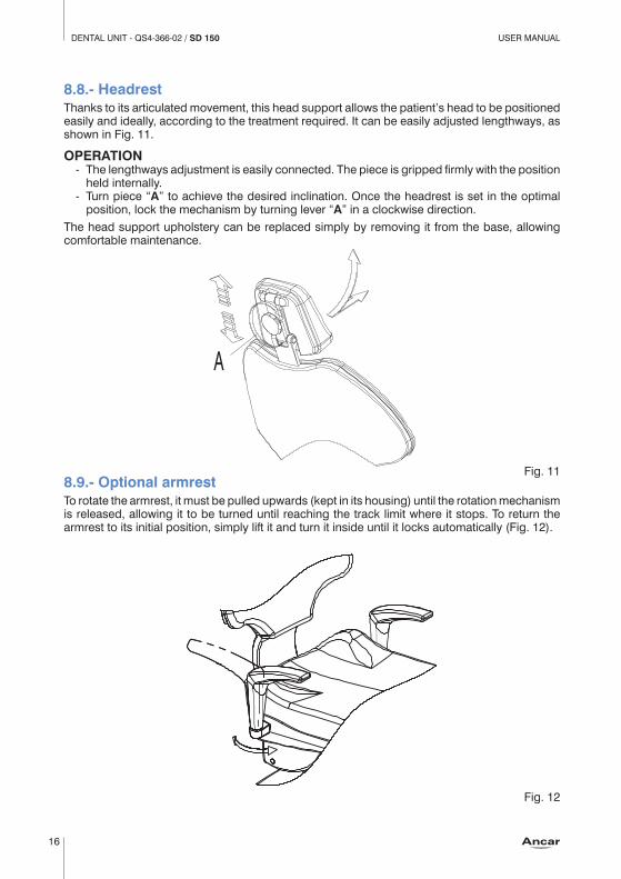
8.8.- HeadrestThanks to its articulated movement, this head support allows the patient’s head to be positioned easily and ideally, according to the treatment required. It can be easily adjusted lengthways, as shown in Fig. 11.
OPERATION - The lengthways adjustment is easily connected. The piece is gripped firmly with the position
held internally. - Turn piece “A” to achieve the desired inclination. Once the headrest is set in the optimal
position, lock the mechanism by turning lever “A” in a clockwise direction.The head support upholstery can be replaced simply by removing it from the base, allowing comfortable maintenance.
8.9.- Optional armrestTo rotate the armrest, it must be pulled upwards (kept in its housing) until the rotation mechanism is released, allowing it to be turned until reaching the track limit where it stops. To return the armrest to its initial position, simply lift it and turn it inside until it locks automatically (Fig. 12).
A
Fig. 11
Fig. 12

USER MANUAL DENTAL UNIT - QS4-366-02 / SD 150
17
9.- SAFETY MOVEMENTS- The dental chair includes mechanical safety stops for the chair and backrest, ensuring
correct manoeuvering and positioning.- Motor overload control through integrated heat sensors. Should the heat sensors go off,
wait 15 minutes for them to cool.- The backrest safety feature, in the event of pressure or knocks against other objects during
manual or automatic lowering, suspends all chair movement (seat and backrest) before lifting it a few centimeters.
- The base safety feature, in the event of pressure or knocks against other objects during manual or automatic lowering, suspends all chair movement (seat and backrest) before lifting it a few centimeters.
- The cannula safety feature, in the event of any pressure against the arm, or knocking against other objects during manual or automatic lowering, suspends all chair movement (seat and backrest).
- The control pedal safety blocks all movements of the chair (seat and backrest) once the control lever is activated, allowing the user to work in the patient’s oral cavity in complete safety. If the chair is moving, it can also be stopped by activating the pedal level (“B”, figure 5).
- The control pedal safety disables all automatic movements, preventing any inadvertent action due to the sensitivity of the three-way directional button.
- If the chair moves to a memorised location, pressing any key on the directional keypad (main and auxiliary) or the pedal will stop the unit.
10.- CLEANING AND STERILISING When cleaning your dental unit, it is essential to use neutral products. Cleaning products with high chemical content can damage plastic parts or upholstery. When cleaning, take care not to wet the equipment too much, as its interior is made up of electrical components. Various specialists in the dental hygiene industry offer a wide range of cleaning products for achieving optimum results.
Before being shipped, all ANCAR equipment is thoroughly cleaned using ECO-JET1 Cattani Magolia disinfectant spray.
For cleaning and disinfecting the different parts of the system, please check: - Section “Cannula Support”. - Appendix 1, “Cattani System and Suction”. - Appendix 2, “Metasys System and Suction” - Appendix 3, “Cleaning other parts of the unit” - Appendix 4, “Durr Dental VS3000 Suction System”. - Appendix 5, “3F / 6F Syringe Maintenance”. - Appendix 6, “Precautions for using ultrasounds”.
STERILISING AND AUTOCLAVE.
135º C Hand instruments should be sterilised in an autoclave at a temperature of 135º C; it is however recommendable to following the instructions of the instrument manufacturer.Cannulas, the cannula-holder and tubes can also be sterilised. Check the section entitled “Cannula support”.We remind you that regular maintenance and proper use of the unit will prolong its working life.

USER MANUALDENTAL UNIT - QS4-366-02 / SD 150
18
11.- TECHNICAL DATAVoltage 220-240 V~Frequency 50 HzAir pressure 5.5 BarWater pressure 3 BarPower 900 WElectrical protection type IOperation type IntermittentMaximum load (patient) 160 Kg.Maximum load (instrument tray) 2 Kg.Electric micromotor instrument 24V dc /65 WInstrument light Bulbs-LEDs, 3 – 3.5 V / 2,5 WUltrasound 24Vac / 35 W.Polymer LED 24V ac / 150 W.Syringe 3F --Syringe 6F (optional) 24Vac / 150 W.Operator light 17Vac / 95 W.Operator light 25,000 lux / 80cm.Unit standard 93/42/EEC Class IIaInsulation type Type BUnit net/gross weight 240 Kg. / 290 Kg.Dental unit type Electro-pneumaticInstallation type PermanentMain fuse T 6.3A / L / 250V Movement Panel Fuse, 24V line T 32 mA / L / 250V Primary transformer fuse, 9015093 PCB TT 2.5A / L / 250V Line protection 24V ac (ye/ye) Polyswitch RUE60017V ac line protection (re/re) Polyswitch RUE600 + RUE185Auxiliary outputs 24V ac 4 x water unitAuxiliary output 24V ac 1 x circuit boxSuction connection 500W / 230V. Relay 20A/250VAuxiliary connection Free contact pot. 250V/5A

USER MANUAL DENTAL UNIT - QS4-366-02 / SD 150
19
APPENDIX 1. CLEANING AND DISINFECTING OF CATTANI GLASS, CANNULAS AND BASIN
Before removing the water unit cover or taking out the vessel, disconnect the dental unit from the mains by turning off the general power switch. Use suitable protective gloves.
As shown in Figure 13, remove the outer cover of the water unit (A) by first pulling lightly towards you and then lifting.Note that this should be gripped is held in place from the top using 2 magnets (B) and below using the supports (C). You will find the vessel installed (D).
Vessel, once at the end of each day.To remove (G), switch off (I) and pull down the two rings (F). Grip the cover (E), lift it slightly and pull towards you from the vessel (G). Also clean the support (H). Replace the vessel following the instructions in reverse. Use the Puli-Jet (Cattani) and water.
Cannula circuit, at lunch time and at night.Cleaning and disinfecting: Use Cattani Pulijet.Concentration: 50cl per litre of water. Take in water through each cannula.
External cannula surfaces, after each treatmentDisinfectant: Eco-Jet Cattani.
Rinse basin with water after each treatment.
Cannula filter: foamless disinfectantUse anti-odour tablets for the cannula filter.
E
IG
FF
H
Fig. 14 (I) Rapid connector.
Caution
Do not clean with foam. Do not use sodium hypochlorite.
B D
C
A
Fig. 13

USER MANUALDENTAL UNIT - QS4-366-02 / SD 150
20
APPENDIX 2. METASYS AMALGAM SEPARATOR
Before removing the water unit cover or taking out the vessel, disconnect the dental unit from the mains by turning off the general power switch. Use suitable protective gloves.
As shown in figure 13, remove the outer cover of the water unit (A), by first pulling it lightly towards you then lifting. Note that it is held at the top using 2 magnets (B) and below using the supports (C). You will find the tank installed (D).Before carrying out any maintenance, cleaning or disinfecting procedures, to check the working order of the unit or should you have any doubts, please refer to the original manufacturer instructions included in the documentation delivered with the dental unit. Always use cleaning and disinfecting products recommended by the manufacturer.
D
Fig. 15

USER MANUAL DENTAL UNIT - QS4-366-02 / SD 150
21
APPENDIX 3. CLEANING AND DISINFECTING OTHER PARTS OF THE UNIT. OTHER SAFETY PRECAUTIONS: UNIT, LIGHT, ELECTRIC
Cleaning and disinfecting
Always disconnect the unit from the mains before carrying out any procedures.
Do not wet or flood the unit with water.
Do not use domestic detergents or disinfecting foams.
Cleaning upholstered areasClean periodically with a soapy solution.
Cleaning polyurethane areas (unit base cover, upholstery support, lifting mechanism covers)Polyurethane areas must be cleaned using a cloth soaked in soapy water. It is recommended to avoid using concentrates, detergents or strong abrasives to remove difficult stains.Clean regularly.
Cleaning and disinfecting exterior metal parts (excluding instruments)Use any product with an antimicrobial, fungicidal, sporicidal or virucidal action that is compatible with the medical industry.
Cleaning and Disinfecting the Column Arm and LightSpray disinfectant. Do not spray on hot surfaces.
To disinfect the dental light, wait for the head to cool.
Regularly disinfect these parts using a disinfectant with at least an antimicrobial and fungicidal action. To clean the light, head and handles, use a damp cloth. Clean reflective surfaces using a dry cloth.
Check manufacturer instructions.
Cleaning and disinfecting the Basin/Spittoon.Use disinfectants recommended by Cattani or Metasys. See appendices I and II.
Cleaning and disinfecting the water unitRegular cleaning and disinfecting: use antimicrobial, fungicidal, virucidal and sporicidal disinfectant.
Cleaning and disinfecting the instrument tray, auxiliary tray and hoses.Cleaning and disinfecting: clean after each treatment using antimicrobial, fungicidal, virucidal and sporicidal disinfectant.

USER MANUALDENTAL UNIT - QS4-366-02 / SD 150
22
APPENDIX 4. DURR VSA300 SUCTION SYSTEM. MAINTENANCE OF THE SUCTION SYSTEM TOGETHER WITH THE SPITTOON VALVE
Before removing the cover of the water unit, disconnect the dental unit from the mains by deactivating the general power switch.
Use suitable protective gloves.As shown in figure 13, remove the outer cover of the water unit (A), by first pulling it lightly towards you then lifting. Note that it is held at the top using 2 magnets (B) and below using the supports (C). The suction system installed contains is located inside.Before carrying out any maintenance, cleaning or disinfecting procedures, to check the working order of the unit or should you have any doubts, please refer to the original manufacturer instructions included in the documentation delivered with the dental unit. Always use cleaning and disinfecting products recommended by the manufacturer.
D
E
Fig. 16

USER MANUAL DENTAL UNIT - QS4-366-02 / SD 150
23
APPENDIX 5. MINILIGHT SYRINGE (LUZZANI)
GENERALThe Minilight syringe is an instrument designed exclusively for dental use, its function being to introduce air and water (individually or simultaneously, at either room or body temperature) into the area of operation to keep it continuously clean and dry.
GENERAL CHARACTERISTICS The Minilight syringe has been designed using state of the art ergonomics to facilitate use and to allow rapid cleaning and sterilisation. Both the tip and the outer grip are easily removable, allowing the instrument to be completely disinfected and sterilised in the autoclave at 135°C. Grips are available in different shapes and colours according to the dentist’s preferences: straight or L-shaped. Furthermore, the air and water may be heated to body temperature to avoid patient irritation from using colder room temperature air or water.
MODELSThe models differ according to the number of features available: - 3F cold water/air spray - 5F cold water/hot and cold air/hot and cold spray - 6F hot and cold water/air/spray - Air or water only - L with LightThe Minilight syringe version is shown above. The handles can be interchanged on all versions: technopolymer curve or straight stainless steel.
CE MARKINGAll products carry CE marking.
PRODUCT BATCHEach product can be traced by a serial number located on the bottom, which identifies the exact batch of production. This number can be used to find out the date of manufacture, in relation to the control panel.
GUARANTEEThe product is guaranteed by our company for 12 months after delivery. Any unauthorised modification or handling will automatically void the guarantee. The company therefore accepts no responsibility for damages to people, animals or other objects due to misuse of the equipment. For any disputes, the competent authority is the Milan tribunal in Italy.
TECHNICAL FEATURES Type B, insulation class II, intermittent function: 10 seconds ON, 20 seconds OFF.
ITEM 6F 5F 3F
SUPPLY VOLTAGE VCA 24 24 ***
CURRENT CONSUMPTION A 4.3 0.7 ***
MAX. ELECTRIC. POWER W 103 0.7 ***
MAX. WATER PRESSURE BAR 2.5 2.5 2.5
MAX. AIR PRESSURE BAR 4.5 4.5 4.5
MAX. AIR CAPACITY NI/min 10 10 10
MAX. WATER CAPACITY Cc/min 110 110 110

USER MANUALDENTAL UNIT - QS4-366-02 / SD 150
24
INSTALLATIONThe unit may only be connected by an Antoni Carles-authorised technician.
NORMAL USE - To introduce cold water into the area of operation, press the left button on the handle. - To introduce cold air into the area of operation, press the right button on the handle. - To introduce a cold air and water spray, press both buttons on the handle simultaneously. - To introduce warm water into the area of operation, turn the switch on the base of the
handle to the right (the green indicator will light up) and press the left button on the handle (only on models 6F and L).
- To introduce warm air into the area of operation, turn the switch on the base of the handle to the right and press the right button on the handle (only on models 6F and L).
- To introduce warm a water and air spray into the area of operation, turn the switch on the base of the handle to the right and press the two buttons on the handle simultaneously (only on models 5F, 6F and L).
Note: The switch is used to select between warm and cold functions. The water or air is heated instantaneously upon use. For this reason, the handle can be left constantly in the “on” position without causing any problems or danger.
LC LEANING OR DISINFECTING
135º C
After each intervention and to maximise hygiene standards, the syringe can be cleaned and sterilised. This is done through the following phases: - Remove the tip (unscrewing it at the mouth) and/or the complete handle
(pressing the button on the handle bottom upwards). - Clean with a cloth, removing any stains or dirt. - Place in the autoclave with the steam set at 135°C for 20 minutes.
MAINTENANCEThe unit requires no specific maintenance, except for the regular cleaning and sterilisation described above. Avoid all kinds of lubrication, since this can cause irreparable damage to the syringe.
SURFACES AND COMPONENTSThe product contains no dangerous, toxic or harmful components, nor does it come into contact with any such products during manufacture.

USER MANUAL DENTAL UNIT - QS4-366-02 / SD 150
25
APPENDIX 6. SAFETY OBSERVATIONS
GENERAL PRECAUTIONSRead all necessary manuals.Keep all manuals – dental unit, chair, instruments, light and additional kits – in a safe place for future reference.Before switching on the unit, read all appendices in this manual.Upon first start-up: carry out a thorough clean of the water channels by passing a solution of water and disinfectant through all water pipes connected to the instruments and water unit.Disconnect the unit from the mains, turning off the general power switch at the end of each working day.If the unit is to be left unused for a long period of time, close the main water and air taps and disconnect the unit from the electrical supply. If the unit is assembled with an amalgam separator system, please do not dispose of the contents of the collection tank once it is full, nor empty the tank into the drain for reuse. Contact the manufacturer of your amalgam separator system or ask our Sales Department. See appendix II.Do not replace fuses yourself. Contact an Antoni Carles-authorised technician through our Sales Department.Hire an authorised maintenance service. This will give you greater safety and prolong the life of the unit. Check with our Sales Department.Regularly check for water or air leaks in the dental unit circuit box, and make sure the area is kept clean and free from humidity, rust or electrolysis.Do not use the unit to support or hold furniture or other materials. Do not stand on the water unit. Do not sit on the water unit support. Do not hang on the light. The unit should only be used by qualified personnel.
DENTAL LIGHT SAFETY PRECAUTIONSMove the light using the handles only; it should not be moved by the lamp head. Do not move it by the lamp head.Do not mark the protective screen.Check regularly that the built-in fan is working correctly. If damaged, it may harm the bulb due to a temperature increase.Do not force the regulator rotation past its minimum and maximum power levels.
REPLACING THE BULBDisconnect the unit from the power supply using the general power switch.Wait 30 minutes for the bulb to cool.Remove the bulb following the manufacturer instructions. Do not touch the new bulb with your hands. Use a cotton cloth.Use special containers to dispose of the old bulb. Consult your local authorities for means of disposal.
Check the light manufacturer instructions.

USER MANUALDENTAL UNIT - QS4-366-02 / SD 150
26
ELECTRICAL SAFETY MEASURESIt is advisable not to use mobile phones in proximity of the dental unit. Observe regular hospital standards.In the event of a light overload, the built-in thermal protection in the 17VCA line may have suspended operation of the unit. Wait 15 minutes for it to reset. Should the problem persist, call the authorised technical service line.In the event of an overload in the instrument line and water unit, the built-in thermal protection in the 24VCA line may have suspended operation of the unit. Wait 15 minutes for it to reset. Should the problem persist, call the authorised technical service line.In the event of an overload in the chair, the thermal protection built into one of the motors may have been triggered and suspended all operations. Wait 15 minutes for it to reset. Should the problem persist, call the authorised technical service line.
PRECAUTIONS ON ELECTROMAGNETIC INTERFERENCESElectronically-controlled instruments may harm patients fitted with pacemakers and/or hearing aids due to possible electromagnetic interferences.The patient may be at risk from the approximate use of electronic scalpels or other electric/electronic equipment which may generate electromagnetic or other types of interference, causing the unit to malfunction. It is advisable to switch off the unit at the mains before using such equipment. Risk of interference with other separate equipment (such as an implant motor). Disconnect the dental unit power supply to prevent any movements indirectly caused through faults and/or through accidental activation of the controls.
PRECAUTIONS ON FLAMMABLE ANAESTHETIC MIXTURES.Do not use the unit/chair in proximity of flammable anaesthetic gas mixtures with oxygen or nitrogen protoxide.

Antoni Carles, S.A.Volta dels Garrofers, 41-42Pol. Ind. Els Garrofers08340 - Vilassar del MarBarcelona - (SPAIN)
T. (34) 93 754 07 97F. (34) 93 759 26 [email protected]