SD-10/12 Description and OWNERS Manual · Owners Manual SD-10 ... a replaceable sacrificial anode...
28
1 Sept, 2011 SD-10/12 Descripon and OWNERS Manual
Transcript of SD-10/12 Description and OWNERS Manual · Owners Manual SD-10 ... a replaceable sacrificial anode...
1
Sept, 2011
SD-10/12 Descriptionand OWNERS Manual
2
Owners Manual SD-10
Section I Introduction II Gear Identification III Brief description IV Operation V Maintenance VI Corrosion protection
3
I Introduction
Customer’s Responsibility The Customer/Operator is responsible to perform the necessary safety checks to ensure that lubrication, cooling, maintenance and recommended practices are strictly followed for safe, enjoyable operation. All Transmission units are covered by a limited warranty. Therefore: In respect to the handling of the transmission units the instructions stated in this manual are to be strictly followed. Maintenance programs described below are valid for the SD-10 transmission unit, not the engine. For the intervals and procedures for maintenance of the engine, refer to the operation manual and maintenance of the engine. CAUTION The manufacturer is not liable for any damages or losses caused by faulty installation, wrong handling of the equipment and/or deficient maintenance. The Customer has to make sure, that any external forces, as well as vibration caused by torsion and bending, are avoided. The interaction between engine, shaft and propeller may lead to torsional vibration, producing a hammering noise of gears and might damage the engine and/or transmission. The Supplier is not liable for such torsional vibration inherent to the installation.
4
I Introduction
This manual includes, among other things, the following four main chapters: III Description This part briefly describes function, operation and design of the SD 10 types. IV Operation This part describes the procedures for operation and all necessary safety measures. V Maintenance This part contains all maintenance and service tasks to be performed by the operator. Important information related to technical reliability and operational safety are highlighted by the identifying words as follows: WARNING Any procedure, practice, condition, statement etc., which is not strictly followed, could result in injury or death of personnel. VI Corrosion Protection This part contains information on corrosion protection.
5
II Gear Identification
Name Plate: The name plate is fixed onto the transmission MODEL SD 10 Transmission Type iA= 2,16 Transmission ratio propeller rotation opposite engine rotation iB= 2,16 Transmission ratio propeller rotation same to a engine rotation SER. N. XXXXXXXX Transmission serial number P/N. 3321 005 011 Transmission part number
6
III Brief Description
The ZF SD-10 Sail Drive is a reliable and well designed piece of machinery. They are of sturdy construction and utmost reliability. Nevertheless the user should make a point of observing the following instructions for installation, operation and maintenance. Failure to do so, or unauthorized changes in the transmission, will preclude all and any warranty claims. A Service Manual is available from the manufacturer.
7
IV Operation
1. General All SD 10 transmissions have been submitted to a test run before shipment. During normal
operation, the transmission should only be shifted with the engine at idle speed. In emergency cases it is also admissible to shift at higher speeds. Visual checks for leakage should be made from time to time.
WARNING. Work on the transmission must only be performed with the engine and
propeller at standstill. CAUTION. Before the first startup, the transmission must be filled with transmission fluid.
Start the engine only when the transmission is in neutral position. CAUTION. Using the transmission with an insufficient oil level will damage the gears. An
excessive oil level may cause leakage at the shaft seals and the transmission breather, and raise the operating temperature considerably.
8
IV Operation
2. Sailing: Boat sailing, moving in tow or anchoring. When the engine is off and the boat sails, moves in
tow or is anchored, the propeller may turn with the water current. CAUTION. When the boat sails with engine switched off the shift position of the gearbox can be: 1) in neutral position and in this case the propeller is free to rotate. 2) in the opposite position of the travel direction to lock the propeller.
Note: do not put the shifting lever of the gearbox in forward position, otherwise the transmission could be damaged!
WARNING. Do not work on the transmission when being towed, or anchoring in a river because
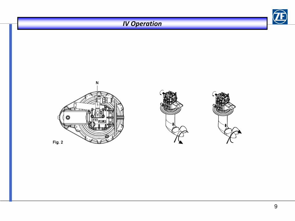
the propeller may rotate. WARNING. When the engine runs idle, but the propeller shaft should not be driven (such as
when charging the battery with the generator), the shifting lever (see Fig. 2) must be held in the neutral position (N) to prevent the boat from moving.
9
IV Operation
10
IV Operation
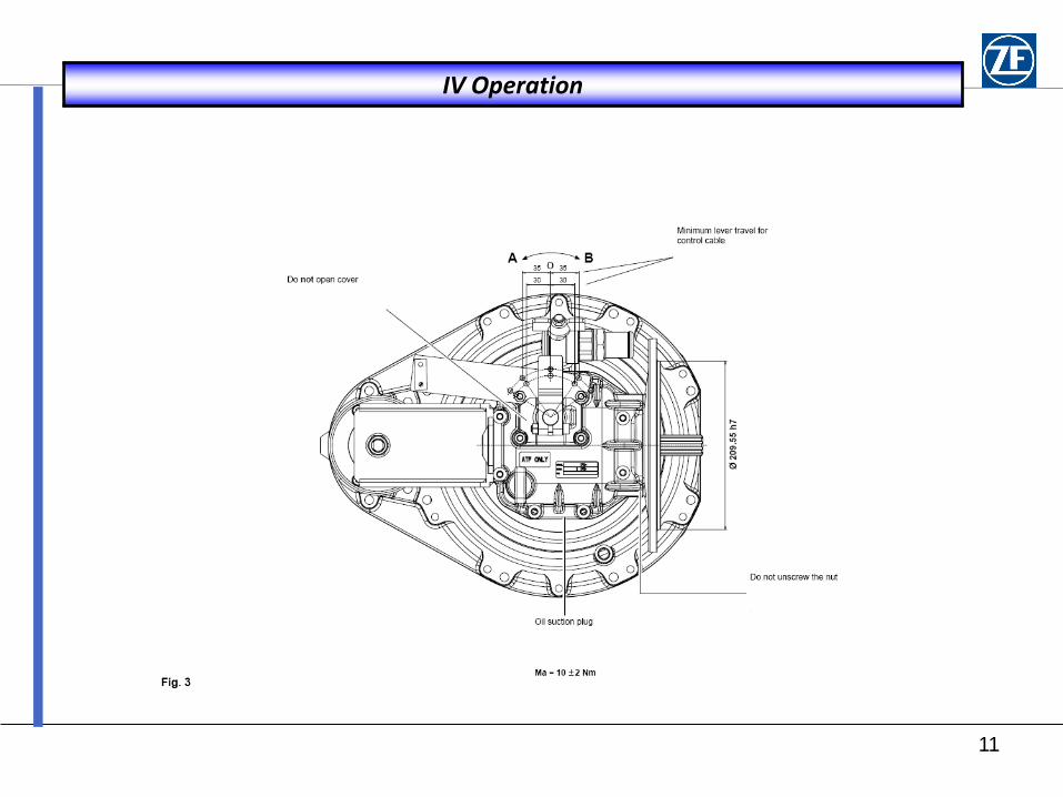
3. Gear shift operation CAUTION. Make certain that control rod or cable is easily movable. 3.1 Lever travel: see Fig. 3 Minimum travel of gear shift lever (O-A=O-B) must be 35 mm (1.3/8") for outer pivot point and 30 mm (1.3/16") for inner pivot point. 3.2 Lever position: In neutral position perpendicular to control rod or cable. Gear shift lever can be fixed in any position by means of clamping screw. Minimum distance between gear shift lever and cover 0.5 mm (0.02"). Opening or loosening of cover requires renewed adjustment (by specialized personnel only). 3.3 Regular checks are required to ensure the strict observance of item 3.1 and 3.2.
11
IV Operation
12
V MAINTENANCE
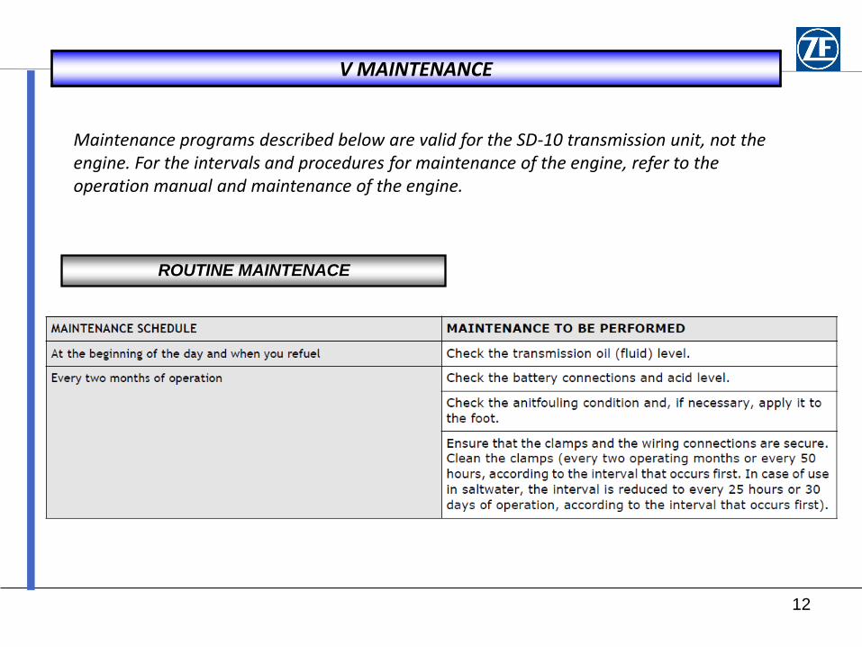
Maintenance programs described below are valid for the SD-10 transmission unit, not the engine. For the intervals and procedures for maintenance of the engine, refer to the operation manual and maintenance of the engine.
ROUTINE MAINTENACE
13
V OIL LEVEL CHECK
1
2
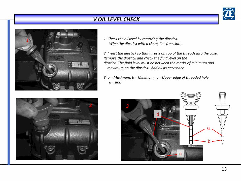
1. Check the oil level by removing the dipstick. Wipe the dipstick with a clean, lint-free cloth. 2. Insert the dipstick so that it rests on top of the threads into the case. Remove the dipstick and check the fluid level on the dipstick. The fluid level must be between the marks of minimum and maximum on the dipstick. Add oil as necessary. 3. a = Maximum, b = Minimum, c = Upper edge of threaded hole d = Rod
3
a
b
c
d
14
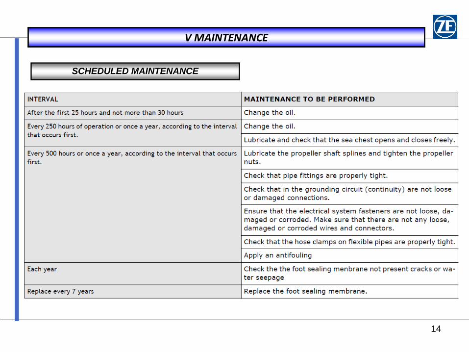
V MAINTENANCE
SCHEDULED MAINTENANCE
15
V OIL CHANGE
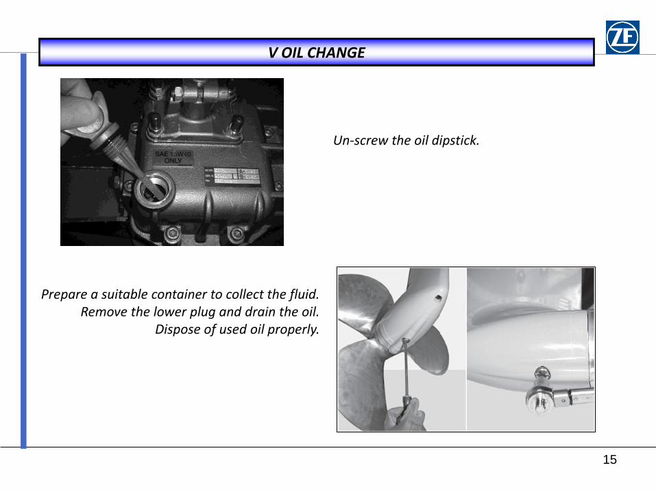
Un-screw the oil dipstick.
Prepare a suitable container to collect the fluid. Remove the lower plug and drain the oil.
Dispose of used oil properly.
16
V OIL CHANGE
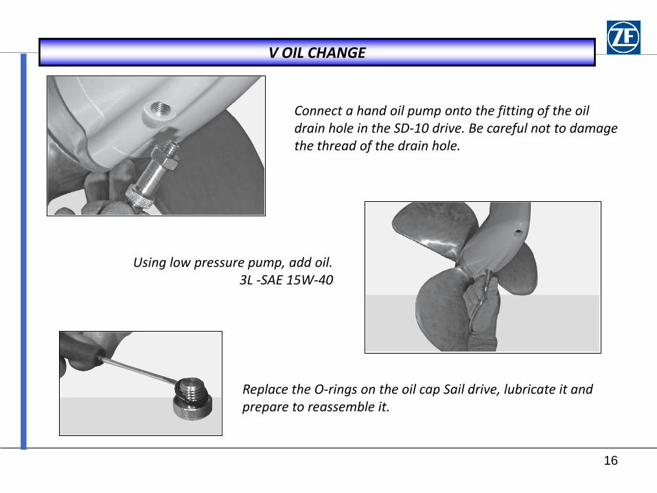
Connect a hand oil pump onto the fitting of the oil drain hole in the SD-10 drive. Be careful not to damage the thread of the drain hole.
Using low pressure pump, add oil. 3L -SAE 15W-40
Replace the O-rings on the oil cap Sail drive, lubricate it and prepare to reassemble it.
17
V OIL CHANGE
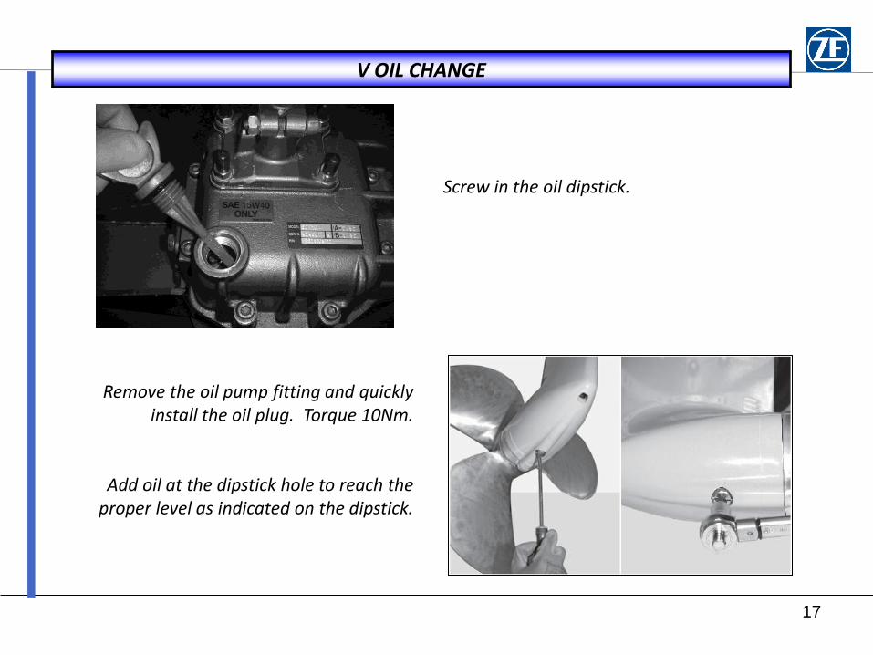
Screw in the oil dipstick.
Remove the oil pump fitting and quickly install the oil plug. Torque 10Nm.
Add oil at the dipstick hole to reach the proper level as indicated on the dipstick.
18
V REMOVING PROPELLER
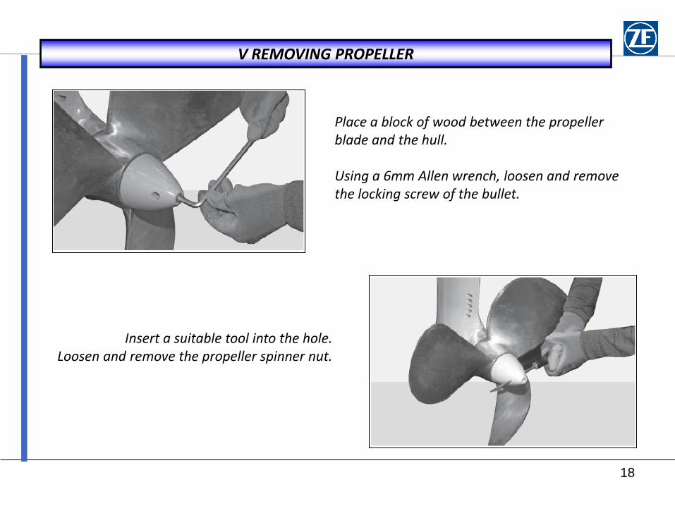
Place a block of wood between the propeller blade and the hull. Using a 6mm Allen wrench, loosen and remove the locking screw of the bullet.
Insert a suitable tool into the hole. Loosen and remove the propeller spinner nut.
19
V REMOVING PROPELLER
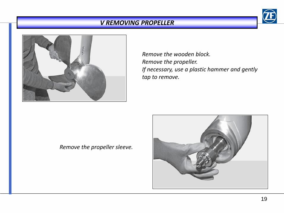
Remove the wooden block. Remove the propeller. If necessary, use a plastic hammer and gently tap to remove.
Remove the propeller sleeve.
20
V INSTALLING PROPELLER
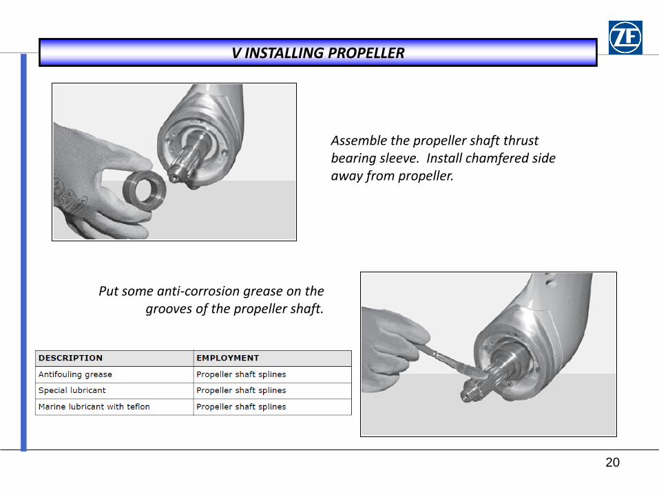
Assemble the propeller shaft thrust bearing sleeve. Install chamfered side away from propeller.
Put some anti-corrosion grease on the grooves of the propeller shaft.
21
V INSTALLING PROPELLER
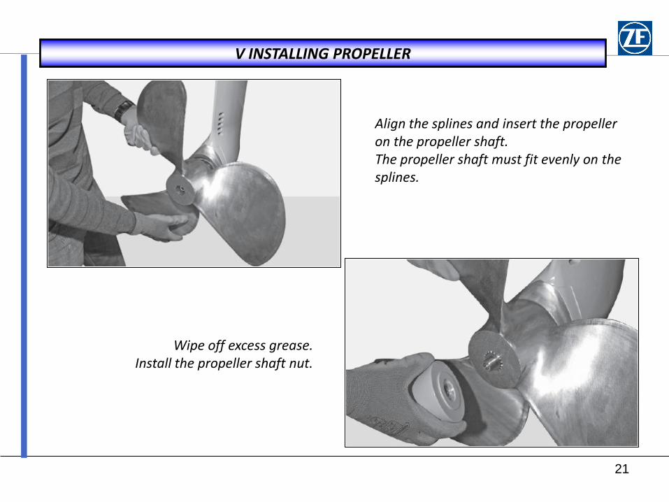
Align the splines and insert the propeller on the propeller shaft. The propeller shaft must fit evenly on the splines.
Wipe off excess grease. Install the propeller shaft nut.
22
V INSTALLING PROPELLER
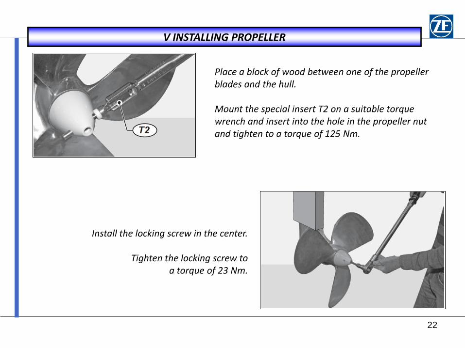
Place a block of wood between one of the propeller blades and the hull. Mount the special insert T2 on a suitable torque wrench and insert into the hole in the propeller nut and tighten to a torque of 125 Nm.
Install the locking screw in the center.
Tighten the locking screw to a torque of 23 Nm.
23
VI CORROSION PROTECTION
The SD-10 is equipped with a replaceable sacrificial anode on the lower leg of the drive. This anode is designed to dissolve in response to electrical current generated while in sea water.
This anode is not designed to accommodate other hardware or other excessive electrical
currents related to additional components or changes to the electrical AC and DC systems on board the vessel.
The ZF SD-10 will be mechanically connected to the powering engine. The design of the electrical system of the engine will impact the selection of a proper galvanic protection system.
Isolated systems: If the engine alternator and starting motor uses an isolated circuit (having both a battery + and – connection terminal) then the system can be treated as an “isolated” system.
Non-Isolated systems: If either the starter motor or the alternator uses a single battery + and uses the body or case as a ground through the engine, then the system of the SD-10 and the engine must be considered as “grounded” to the battery negative and not isolated.
24
VI CORROSION PROTECTION
Suggested actions: For information on this topic, review the published guidelines as contained in ABYC guidebook, Section E-2. Upon final delivery of the vessel a review of the electrical bonding system should be conducted. An expert in the field of electrical bonding should be called upon to review the completed vessel. This review should determine if there is an appropriate amount or sizing of sacrificial anodes installed in order to protect the mechanical components (engine and SD-10) from damage from galvanic corrosion.
Please keep in mind, changes made to the vessels AC and DC systems may impact the protection of the installed anode system.
Damage to the SD-10 as a result of failure to maintain a good balanced galvanic protection system is not the responsibility of ZF Marine.
25
VI ANODE REPLACEMENT
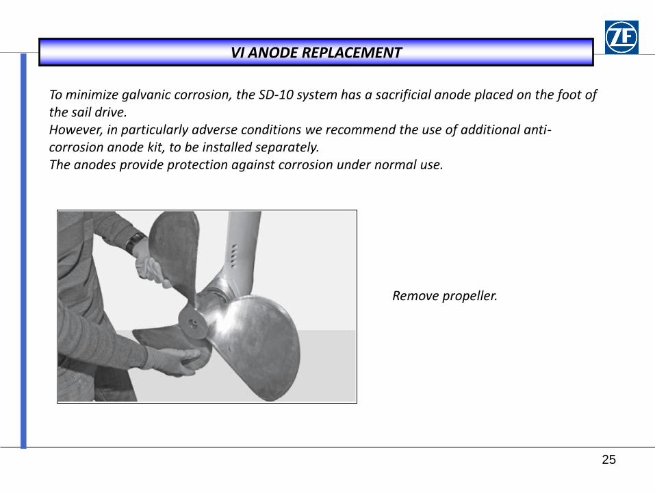
To minimize galvanic corrosion, the SD-10 system has a sacrificial anode placed on the foot of the sail drive. However, in particularly adverse conditions we recommend the use of additional anti-corrosion anode kit, to be installed separately. The anodes provide protection against corrosion under normal use.
Remove propeller.
26
VI ANODE REPLACEMENT
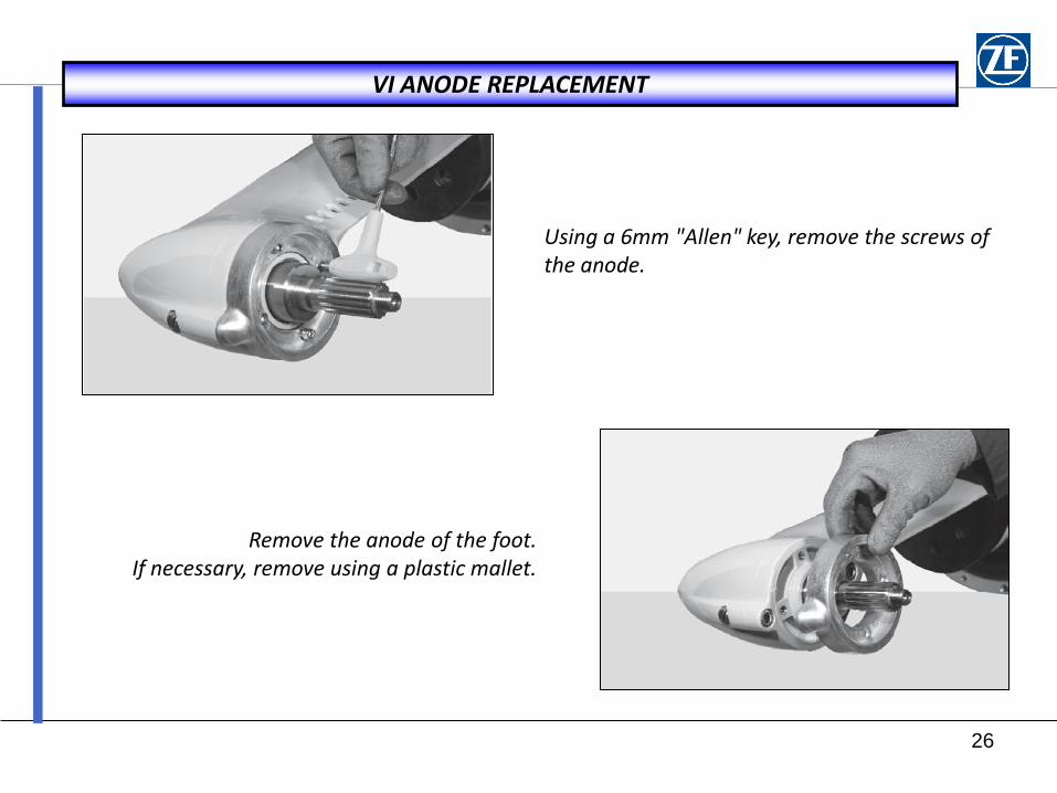
Using a 6mm "Allen" key, remove the screws of the anode.
Remove the anode of the foot. If necessary, remove using a plastic mallet.
27
VI ANODE REPLACEMENT
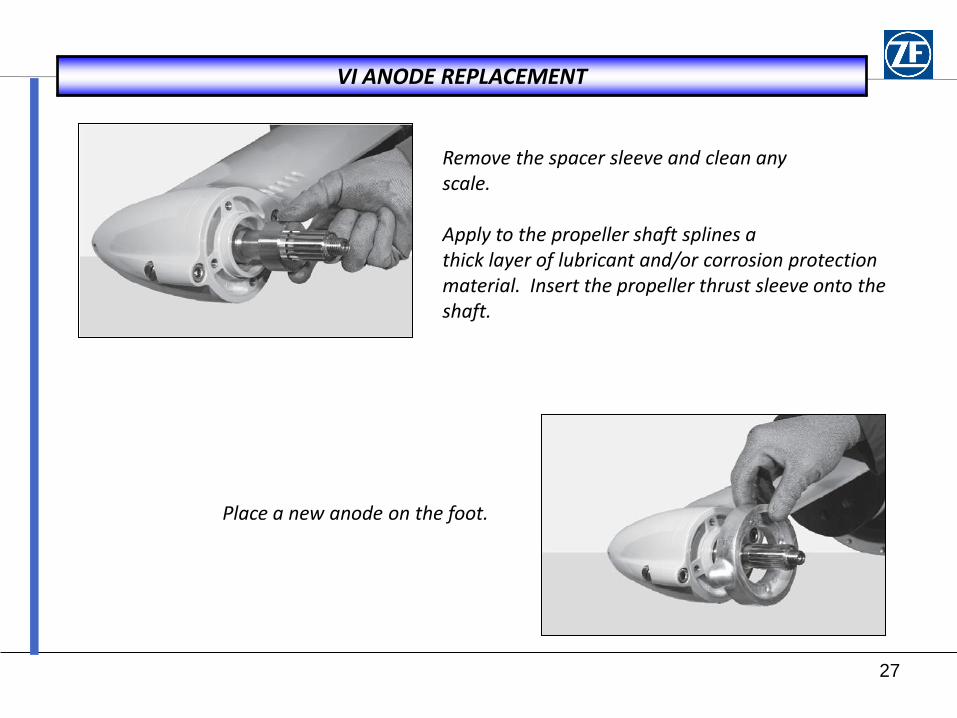
Remove the spacer sleeve and clean any scale. Apply to the propeller shaft splines a thick layer of lubricant and/or corrosion protection material. Insert the propeller thrust sleeve onto the shaft.
Place a new anode on the foot.
28
VI ANODE REPLACEMENT
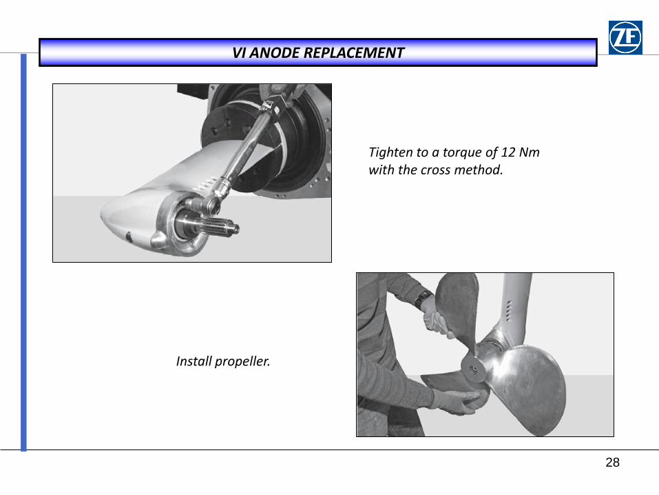
Tighten to a torque of 12 Nm with the cross method.
Install propeller.