SCT Weight Transmitter - Instrumart · PDF fileInstalling Load Cells: The load ... place the...
70
SCT Weight Transmitter 20 Series Installation & Operator’s Manual 131128 Rev C
Transcript of SCT Weight Transmitter - Instrumart · PDF fileInstalling Load Cells: The load ... place the...

SCT Weight Transmitter20 Series
Installation & Operator’s Manual
131128 Rev C

Content
1.0 Introduction........................................................................................................................................ 11.1 Safety. . . . . . . . . . . . . . . . . . . . . . . . . . . . . . . . . . . . . . . . . . . . . . . . . . . . . . . . . . . . . . . . . . . . . . . . . . . . 11.2 Equipment Recommendations . . . . . . . . . . . . . . . . . . . . . . . . . . . . . . . . . . . . . . . . . . . . . . . . . . . . . . . . 2
1.2.1 Correct Installation Of Weighing Instruments . . . . . . . . . . . . . . . . . . . . . . . . . . . . . . . . . . . . . . . . . . . . . . . . . . . . . 21.2.2 Correct Installation Of The Load Cells . . . . . . . . . . . . . . . . . . . . . . . . . . . . . . . . . . . . . . . . . . . . . . . . . . . . . . . . . . 2
1.3 Load Cells . . . . . . . . . . . . . . . . . . . . . . . . . . . . . . . . . . . . . . . . . . . . . . . . . . . . . . . . . . . . . . . . . . . . . . . . 31.3.1 Load Cell Input Test (Quick Access) . . . . . . . . . . . . . . . . . . . . . . . . . . . . . . . . . . . . . . . . . . . . . . . . . . . . . . . . . . . 31.3.2 Load Cell Testing. . . . . . . . . . . . . . . . . . . . . . . . . . . . . . . . . . . . . . . . . . . . . . . . . . . . . . . . . . . . . . . . . . . . . . . . . . 3
1.4 Specifications . . . . . . . . . . . . . . . . . . . . . . . . . . . . . . . . . . . . . . . . . . . . . . . . . . . . . . . . . . . . . . . . . . . . . 41.5 Electrical Connections . . . . . . . . . . . . . . . . . . . . . . . . . . . . . . . . . . . . . . . . . . . . . . . . . . . . . . . . . . . . . . 61.6 LED and Key Functions . . . . . . . . . . . . . . . . . . . . . . . . . . . . . . . . . . . . . . . . . . . . . . . . . . . . . . . . . . . . . 71.7 Instrument Commissioning. . . . . . . . . . . . . . . . . . . . . . . . . . . . . . . . . . . . . . . . . . . . . . . . . . . . . . . . . . . 9
1.7.1 If The Instrument Has Not Been Calibrated . . . . . . . . . . . . . . . . . . . . . . . . . . . . . . . . . . . . . . . . . . . . . . . . . . . . . . 9
2.0 Configuration ................................................................................................................................... 102.1 Calibration . . . . . . . . . . . . . . . . . . . . . . . . . . . . . . . . . . . . . . . . . . . . . . . . . . . . . . . . . . . . . . . . . . . . . . . 12
2.1.1 Theoretical Calibration . . . . . . . . . . . . . . . . . . . . . . . . . . . . . . . . . . . . . . . . . . . . . . . . . . . . . . . . . . . . . . . . . . . . . 132.1.2 Maximum Capacity (NASS ). . . . . . . . . . . . . . . . . . . . . . . . . . . . . . . . . . . . . . . . . . . . . . . . . . . . . . . . . . . . . . . . . 142.1.3 Zero Setting. . . . . . . . . . . . . . . . . . . . . . . . . . . . . . . . . . . . . . . . . . . . . . . . . . . . . . . . . . . . . . . . . . . . . . . . . . . . . 142.1.4 Zero Value Manual Entry . . . . . . . . . . . . . . . . . . . . . . . . . . . . . . . . . . . . . . . . . . . . . . . . . . . . . . . . . . . . . . . . . . . 142.1.5 Weight (Span) Calibration (With Test Weights) . . . . . . . . . . . . . . . . . . . . . . . . . . . . . . . . . . . . . . . . . . . . . . . . . . . 152.1.6 Setting Units of Measure . . . . . . . . . . . . . . . . . . . . . . . . . . . . . . . . . . . . . . . . . . . . . . . . . . . . . . . . . . . . . . . . . . . 162.1.7 Display Coefficient . . . . . . . . . . . . . . . . . . . . . . . . . . . . . . . . . . . . . . . . . . . . . . . . . . . . . . . . . . . . . . . . . . . . . . . . 16
2.2 Filter On The Weight . . . . . . . . . . . . . . . . . . . . . . . . . . . . . . . . . . . . . . . . . . . . . . . . . . . . . . . . . . . . . . . 172.3 Zero Parameters . . . . . . . . . . . . . . . . . . . . . . . . . . . . . . . . . . . . . . . . . . . . . . . . . . . . . . . . . . . . . . . . . . 182.4 SCT20-DN (DeviceNet) Settings. . . . . . . . . . . . . . . . . . . . . . . . . . . . . . . . . . . . . . . . . . . . . . . . . . . . . . 182.5 Analog Output . . . . . . . . . . . . . . . . . . . . . . . . . . . . . . . . . . . . . . . . . . . . . . . . . . . . . . . . . . . . . . . . . . . . 192.6 Profibus Settings. . . . . . . . . . . . . . . . . . . . . . . . . . . . . . . . . . . . . . . . . . . . . . . . . . . . . . . . . . . . . . . . . . 202.7 SCT20-IP (EtherNet/IP) Settings. . . . . . . . . . . . . . . . . . . . . . . . . . . . . . . . . . . . . . . . . . . . . . . . . . . . . . 212.8 SCT20-IP (Ethernet TCP/IP) Settings . . . . . . . . . . . . . . . . . . . . . . . . . . . . . . . . . . . . . . . . . . . . . . . . . . 222.9 Serial Communication Settings . . . . . . . . . . . . . . . . . . . . . . . . . . . . . . . . . . . . . . . . . . . . . . . . . . . . . . 24
2.9.1 RS-485 Serial Communication. . . . . . . . . . . . . . . . . . . . . . . . . . . . . . . . . . . . . . . . . . . . . . . . . . . . . . . . . . . . . . . 262.10 Outputs And Inputs Configuration . . . . . . . . . . . . . . . . . . . . . . . . . . . . . . . . . . . . . . . . . . . . . . . . . . . 272.11 Test . . . . . . . . . . . . . . . . . . . . . . . . . . . . . . . . . . . . . . . . . . . . . . . . . . . . . . . . . . . . . . . . . . . . . . . . . . . 292.12 Setpoints Programming . . . . . . . . . . . . . . . . . . . . . . . . . . . . . . . . . . . . . . . . . . . . . . . . . . . . . . . . . . . 302.13 Reserved For The Installer . . . . . . . . . . . . . . . . . . . . . . . . . . . . . . . . . . . . . . . . . . . . . . . . . . . . . . . . . 31
2.13.1 Menu Locking . . . . . . . . . . . . . . . . . . . . . . . . . . . . . . . . . . . . . . . . . . . . . . . . . . . . . . . . . . . . . . . . . . . . . . . . . . 312.13.2 Menu Unlocking . . . . . . . . . . . . . . . . . . . . . . . . . . . . . . . . . . . . . . . . . . . . . . . . . . . . . . . . . . . . . . . . . . . . . . . . 312.13.3 Temporary Menu Unlocking. . . . . . . . . . . . . . . . . . . . . . . . . . . . . . . . . . . . . . . . . . . . . . . . . . . . . . . . . . . . . . . . 312.13.4 Default Scale . . . . . . . . . . . . . . . . . . . . . . . . . . . . . . . . . . . . . . . . . . . . . . . . . . . . . . . . . . . . . . . . . . . . . . . . . . . 312.13.5 Program Selection - Reverse: . . . . . . . . . . . . . . . . . . . . . . . . . . . . . . . . . . . . . . . . . . . . . . . . . . . . . . . . . . . . . . 322.13.6 Program Selection - Not Legal: . . . . . . . . . . . . . . . . . . . . . . . . . . . . . . . . . . . . . . . . . . . . . . . . . . . . . . . . . . . . . 322.13.7 Keypad Or Display Locking . . . . . . . . . . . . . . . . . . . . . . . . . . . . . . . . . . . . . . . . . . . . . . . . . . . . . . . . . . . . . . . . 32
3.0 Operation.......................................................................................................................................... 333.1 Semi-automatic Tare (Net/Gross). . . . . . . . . . . . . . . . . . . . . . . . . . . . . . . . . . . . . . . . . . . . . . . . . . . . . 333.2 Preset Tare (Subtractive Tare Device) . . . . . . . . . . . . . . . . . . . . . . . . . . . . . . . . . . . . . . . . . . . . . . . . . 333.3 Semi-automatic Zero (Weight Zero-setting For Small Variations) . . . . . . . . . . . . . . . . . . . . . . . . . . . 333.4 Peak . . . . . . . . . . . . . . . . . . . . . . . . . . . . . . . . . . . . . . . . . . . . . . . . . . . . . . . . . . . . . . . . . . . . . . . . . . . . 33
© Rice Lake Weighing Systems. All rights reserved. Printed in the United States of America. Specifications subject to change without notice.
Rice Lake Weighing Systems is an ISO 9001 registered company.April 3, 2014
Technical training seminars are available through Rice Lake Weighing Systems.
Course descriptions and dates can be viewed at www.ricelake.com/trainingor obtained by calling 715-234-9171 and asking for the training department.

ii SCT Weight Transmitter Operator’s Manual
Rice Lake continually offers web-based video training on a growing selection
of product-related topics at no cost. Visit www.ricelake.com/webinars.
3.5 Alarms . . . . . . . . . . . . . . . . . . . . . . . . . . . . . . . . . . . . . . . . . . . . . . . . . . . . . . . . . . . . . . . . . . . . . . . . . . 343.6 SCT20-DN (DeviceNet) . . . . . . . . . . . . . . . . . . . . . . . . . . . . . . . . . . . . . . . . . . . . . . . . . . . . . . . . . . . . . 353.7 Profibus . . . . . . . . . . . . . . . . . . . . . . . . . . . . . . . . . . . . . . . . . . . . . . . . . . . . . . . . . . . . . . . . . . . . . . . . . 363.8 SCT20-IP (EtherNet/IP) . . . . . . . . . . . . . . . . . . . . . . . . . . . . . . . . . . . . . . . . . . . . . . . . . . . . . . . . . . . . . 413.9 SCT20-TCP/IP (Ethernet TCP/IP) . . . . . . . . . . . . . . . . . . . . . . . . . . . . . . . . . . . . . . . . . . . . . . . . . . . . . 443.10 Modbus/TCP . . . . . . . . . . . . . . . . . . . . . . . . . . . . . . . . . . . . . . . . . . . . . . . . . . . . . . . . . . . . . . . . . . . . 463.11 Modbus-RTU Protocol . . . . . . . . . . . . . . . . . . . . . . . . . . . . . . . . . . . . . . . . . . . . . . . . . . . . . . . . . . . . 463.12 ASCII Bidirectional Protocol . . . . . . . . . . . . . . . . . . . . . . . . . . . . . . . . . . . . . . . . . . . . . . . . . . . . . . . . 523.13 Fast Continuous Transmission Protocol . . . . . . . . . . . . . . . . . . . . . . . . . . . . . . . . . . . . . . . . . . . . . . 573.14 Continuous Transmission Protocol . . . . . . . . . . . . . . . . . . . . . . . . . . . . . . . . . . . . . . . . . . . . . . . . . . 573.15 Interface to Remote Display . . . . . . . . . . . . . . . . . . . . . . . . . . . . . . . . . . . . . . . . . . . . . . . . . . . . . . . . 583.16 Communication Examples . . . . . . . . . . . . . . . . . . . . . . . . . . . . . . . . . . . . . . . . . . . . . . . . . . . . . . . . . 59
SCT Weight Transmitter Limited Warranty ............................................................................................... 62For More Information ................................................................................................................................ 63

Introduction 1
1.0 IntroductionManuals can be viewed and downloaded from the Rice Lake Weighing Systems website atwww.ricelake.com.
1.1 SafetySafety Symbol Definitions:
Indicates a potentially hazardous situation that, if not avoided could result in death or serious injury, andincludes hazards that are exposed when guards are removed.
Indicates information about procedures that, if not observed, could result in damage to equipment orcorruption to and loss of data.
Do not operate or work on this equipment unless you have read and understand the instructions andwarnings in this Manual. Contact any Rice Lake Weighing Systems dealer for replacement manuals.Proper care is your responsibility.
General Safety
Failure to heed may result in serious injury or death.
Risk of electrical shock. No user serviceable parts. Refer to qualified service personnel for service.
The unit has no power switch, to completely remove D/C power from the unit, disconnect the D/C power cable from themain socket.
DO NOT allow minors (children) or inexperienced persons to operate this unit.
DO NOT operate without all shields and guards in place.
DO NOT use for purposes other then weighing applications.
DO NOT place fingers into slots or possible pinch points.
DO NOT use this product if any of the components are cracked.
DO NOT make alterations or modifications to the unit.
DO NOT remove or obscure warning labels.
DO NOT use near water.
WARNING
Important
WARNING
2 SCT Weight Transmitter Operator’s Manual
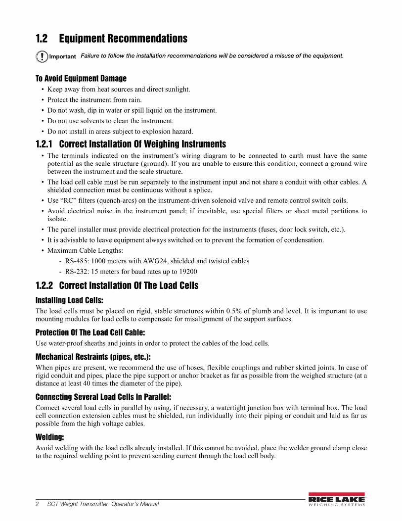
1.2 Equipment RecommendationsFailure to follow the installation recommendations will be considered a misuse of the equipment.
To Avoid Equipment Damage• Keep away from heat sources and direct sunlight.
• Protect the instrument from rain.
• Do not wash, dip in water or spill liquid on the instrument.
• Do not use solvents to clean the instrument.
• Do not install in areas subject to explosion hazard.
1.2.1 Correct Installation Of Weighing Instruments• The terminals indicated on the instrument’s wiring diagram to be connected to earth must have the same
potential as the scale structure (ground). If you are unable to ensure this condition, connect a ground wirebetween the instrument and the scale structure.
• The load cell cable must be run separately to the instrument input and not share a conduit with other cables. Ashielded connection must be continuous without a splice.
• Use “RC” filters (quench-arcs) on the instrument-driven solenoid valve and remote control switch coils.
• Avoid electrical noise in the instrument panel; if inevitable, use special filters or sheet metal partitions toisolate.
• The panel installer must provide electrical protection for the instruments (fuses, door lock switch, etc.).
• It is advisable to leave equipment always switched on to prevent the formation of condensation.
• Maximum Cable Lengths:
- RS-485: 1000 meters with AWG24, shielded and twisted cables
- RS-232: 15 meters for baud rates up to 19200
1.2.2 Correct Installation Of The Load CellsInstalling Load Cells: The load cells must be placed on rigid, stable structures within 0.5% of plumb and level. It is important to usemounting modules for load cells to compensate for misalignment of the support surfaces.
Protection Of The Load Cell Cable: Use water-proof sheaths and joints in order to protect the cables of the load cells.
Mechanical Restraints (pipes, etc.): When pipes are present, we recommend the use of hoses, flexible couplings and rubber skirted joints. In case ofrigid conduit and pipes, place the pipe support or anchor bracket as far as possible from the weighed structure (at adistance at least 40 times the diameter of the pipe).
Connecting Several Load Cells In Parallel: Connect several load cells in parallel by using, if necessary, a watertight junction box with terminal box. The loadcell connection extension cables must be shielded, run individually into their piping or conduit and laid as far aspossible from the high voltage cables.
Welding: Avoid welding with the load cells already installed. If this cannot be avoided, place the welder ground clamp closeto the required welding point to prevent sending current through the load cell body.
Important

Introduction 3
Windy Conditions - Shocks - Vibrations: The use of weigh modules is strongly recommended for all load cells to compensate for misalignment of thesupport surfaces. The system designer must ensure that the scale is protected against lateral shifting and tippingrelating to shocks and vibration, windy conditions, seismic conditions and stability of the support structure.
Grounding The Weighed Structure: By means of a 10ga solid or braided wire or braided grounding strap, connect the load cell upper support plate withthe lower support plate, then connect all the lower plates to a single earth ground. Once installed electrostaticcharges accumulated are discharged to the ground without going through or damaging the load cells. Failure toimplement a proper grounding system might not affect the operation of the weighing system; this, however, doesnot rule out the possibility that the load cells and connected instrument may become damaged by ESD. It isforbidden to ensure grounding system continuity by using metal parts contained in the weighed structure.(see Figure 1-1.)
Figure 1-1. Installation Recommendations
1.3 Load Cells1.3.1 Load Cell Input Test (Quick Access)
1. From the weight display, press for three seconds.
2. The display will read NU-CEL. Press .
3. The response signal of the load cell is displayed, expressed in mV with four decimals. Press three timesto exit test mode.
1.3.2 Load Cell TestingLoad Cell Resistance Measurement (Use A Digital Multimeter):
• Disconnect the load cells from the instrument and check that there is no moisture in the load cell junction boxcaused by condensation or water infiltration. If so, drain the system or replace it if necessary.
• The value between the positive signal wire and the negative signal wire must be equal or similar to the oneindicated in the load cell data sheet (output resistance).
• The value between the positive excitation wire and the negative excitation wire must be equal or similar to theone indicated in the load cell data sheet (input resistance).
• The insulation value between the shield and any other load cell wire and between any other load cell wire andthe body of the load cell must be higher than 20 Mohm (mega ohms).
Uses ground plate to continue ground.
Uses structure to continue ground.
4 SCT Weight Transmitter Operator’s Manual
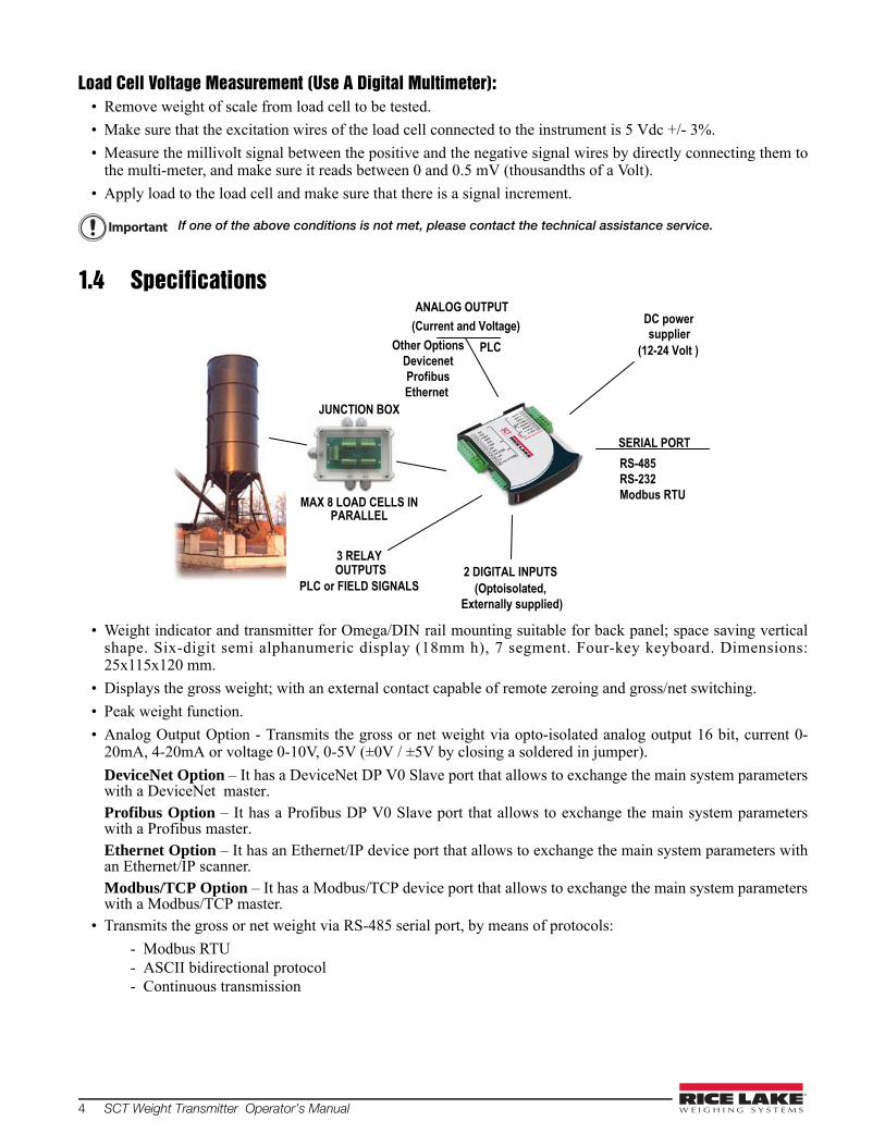
Load Cell Voltage Measurement (Use A Digital Multimeter):• Remove weight of scale from load cell to be tested.
• Make sure that the excitation wires of the load cell connected to the instrument is 5 Vdc +/- 3%.
• Measure the millivolt signal between the positive and the negative signal wires by directly connecting them tothe multi-meter, and make sure it reads between 0 and 0.5 mV (thousandths of a Volt).
• Apply load to the load cell and make sure that there is a signal increment.
If one of the above conditions is not met, please contact the technical assistance service.
1.4 Specifications
• Weight indicator and transmitter for Omega/DIN rail mounting suitable for back panel; space saving verticalshape. Six-digit semi alphanumeric display (18mm h), 7 segment. Four-key keyboard. Dimensions:25x115x120 mm.
• Displays the gross weight; with an external contact capable of remote zeroing and gross/net switching.
• Peak weight function.
• Analog Output Option - Transmits the gross or net weight via opto-isolated analog output 16 bit, current 0-20mA, 4-20mA or voltage 0-10V, 0-5V (±0V / ±5V by closing a soldered in jumper).
DeviceNet Option – It has a DeviceNet DP V0 Slave port that allows to exchange the main system parameterswith a DeviceNet master.Profibus Option – It has a Profibus DP V0 Slave port that allows to exchange the main system parameterswith a Profibus master.Ethernet Option – It has an Ethernet/IP device port that allows to exchange the main system parameters withan Ethernet/IP scanner.Modbus/TCP Option – It has a Modbus/TCP device port that allows to exchange the main system parameterswith a Modbus/TCP master.
• Transmits the gross or net weight via RS-485 serial port, by means of protocols:
- Modbus RTU- ASCII bidirectional protocol- Continuous transmission
Important
ANALOG OUTPUT (Current and Voltage)
PLC
PLC or FIELD SIGNALS 2 DIGITAL INPUTS
(Optoisolated, Externally supplied)
JUNCTION BOX
3 RELAY
MAX 8 LOAD CELLS IN PARALLEL
RS-485RS-232Modbus RTU
SERIAL PORT
DC power supplier
(12-24 Volt ) Other OptionsDevicenetProfibusEthernet
OUTPUTS

Introduction 5
File Number:E151461
Power Supply and Consumption (VDC) 12 - 24 VDC +/- 10% ; 5 W
No. of Load Cells in Parallel And Supply max 8 ( 350 ohm ) ; 5VDC/120mA
Linearity / Analog Output Linearity < 0.01% F.S. / < 0.01% F.S.
Thermal Drift < 0.0005 % F.S. /°C ;< 0.003 % F.S./°C (Analog Only)
A/D Converter 24 bit (16.000.000 points)
Max Divisions (With Measurement Range: +/-10mv = Sens. 2mv/v) +/- 999999
Measurement Range +/- 39 mV
Max Sensitivity of Usable Load Cells +/-7mV/V
Max Conversions Per Second 300 conversions/second
Display Range - 999999 ; + 999999
No. of Decimals / Display Increments 0 - 4 / x 1 x 2 x 5 x 10 x 20 x 50 x 100
Digital Filter / Readings Per Second 0.060–7sec/5-300Hz (Analog,DeviceNet)0.012-7sec/5-300Hz (Ethernet,Profibus)
Relay Logic Outputs N.3 - max 115 VAC ; 150mA
Logic Inputs N.2 - optoisolated 5 - 24 VDC PNP
Serial Ports RS-485 (RS-232)
Baud Rate 2400, 4800, 9600, 19200, 38400, 115200
Humidity (Non Condensing) 85 %
Storage Temperature -22° to 176°F (- 30° to + 80°C)
Working Temperature -4° to 140°F (- 20° to + 60°C)
Optoisolated Analog Output 16 Bit - 65535 Divisions 0-20 mA; 4-20 mA (max 300 ohm); 0-10 VDC; 0-5 VDC; +/- 10 VDC; +/- 5 VDC (min 10 kohm)
Ethernet/IP Port RJ45 10Base-T or 100Base-TX (auto-sensing)
Profibus Port: Baud RateProfibus Port Addresses
to 12 Mbit/s1-99
DeviceNet Port: Baud RateDeviceNet Port: Addresses
125kbit/s, 250kbit/s, 500kbit/s1.63
Modbus/TCP Port RJ45 10Base-T or 100Base-TX (auto-sensing)
Table 1-1. Specifications
6 SCT Weight Transmitter Operator’s Manual
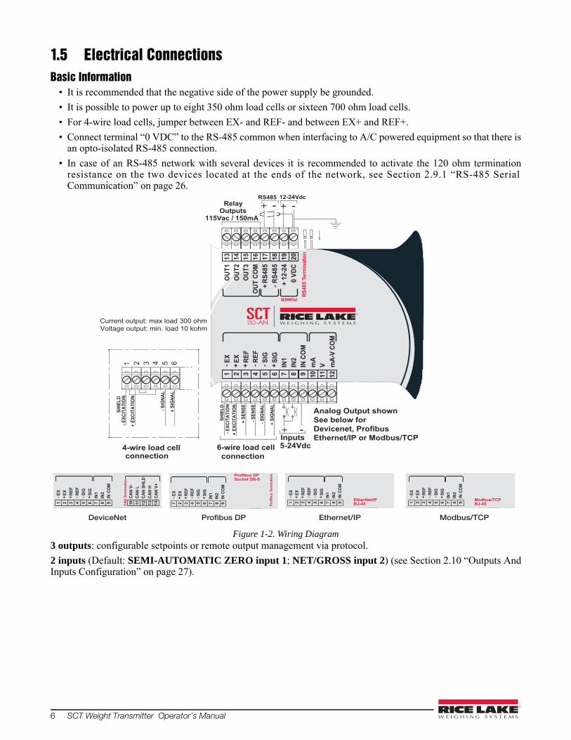
1.5 Electrical ConnectionsBasic Information
• It is recommended that the negative side of the power supply be grounded.
• It is possible to power up to eight 350 ohm load cells or sixteen 700 ohm load cells.
• For 4-wire load cells, jumper between EX- and REF- and between EX+ and REF+.
• Connect terminal “0 VDC” to the RS-485 common when interfacing to A/C powered equipment so that there isan opto-isolated RS-485 connection.
• In case of an RS-485 network with several devices it is recommended to activate the 120 ohm terminationresistance on the two devices located at the ends of the network, see Section 2.9.1 “RS-485 SerialCommunication” on page 26.
Figure 1-2. Wiring Diagram3 outputs: configurable setpoints or remote output management via protocol.
2 inputs (Default: SEMI-AUTOMATIC ZERO input 1; NET/GROSS input 2) (see Section 2.10 “Outputs AndInputs Configuration” on page 27).
+ EX
CITA
TIO
N
- EXC
ITAT
ION
4-wire load cellconnection
SHIE
LD
+ SI
GNA
L
- SIG
NAL
1 2 3 4 5 6
RS485Relay
Outputs115Vac / 150mA
12-24Vdc
- SIG
NAL
+ EX
CITA
TIO
N
SHIE
LD- E
XCIT
ATIO
N
- SEN
SE
+ SE
NSE
Inputs5-24Vdc
+ SI
GNA
L
+ -
Current output: max load 300 ohmVoltage output: min. load 10 kohm
6-wire load cellconnection
Analog Output shownSee below forDevicenet, ProfibusEthernet/IP or Modbus/TCP
RS48
5 Te
rmin
atio
n
POWER
EX- REF
-
1EX+
2RE
F+
3
SIG
+6
IN1
7IN
28
IN C
OM
9m
A10
V11
mA-
V CO
M124
SIG
-5
OUT
1O
UT2
OUT
3O
UT C
OM
+ RS
485
- RS4
85+
12-2
40
VDC
13 14 15 18 19 2016 17
SCT20-AN
DeviceNet
CAN
V-10 11 12 13 14
CAN
L
CAN
HCA
N V+
CAN
SHLD
CAN
Term
inat
ion
EX- REF
-
1EX+
2RE
F+
3
SIG
+6
IN1
7IN
28
IN C
OM
94SI
G-
5
Profibus DP
EX- REF
-
1EX+
2RE
F+
3
SIG
+6
IN1
7IN
28
IN C
OM
94SI
G-
5 Prof
ibus
Ter
min
atio
n
Ethernet/IP
EX- REF
-
1EX+
2RE
F+
3
SIG
+6
IN1
7IN
28
IN C
OM
94SI
G-
5 EtherNet/IPRJ-45
Profibus DPSocket DB-9
Modbus/TCP
EX- REF
-
1EX+
2RE
F+
3
SIG
+6
IN1
7IN
28
IN C
OM
94SI
G-
5 Modbus/TCPRJ-45
Introduction 7
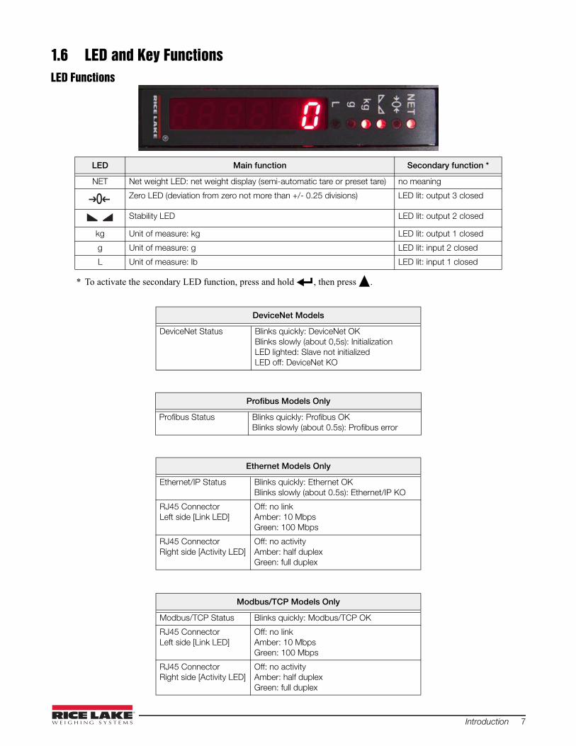
1.6 LED and Key FunctionsLED Functions
* To activate the secondary LED function, press and hold , then press .
LED Main function Secondary function *
NET Net weight LED: net weight display (semi-automatic tare or preset tare) no meaning
Zero LED (deviation from zero not more than +/- 0.25 divisions) LED lit: output 3 closed
Stability LED LED lit: output 2 closed
kg Unit of measure: kg LED lit: output 1 closed
g Unit of measure: g LED lit: input 2 closed
L Unit of measure: lb LED lit: input 1 closed
DeviceNet Models
DeviceNet Status Blinks quickly: DeviceNet OKBlinks slowly (about 0,5s): InitializationLED lighted: Slave not initializedLED off: DeviceNet KO
Profibus Models Only
Profibus Status Blinks quickly: Profibus OKBlinks slowly (about 0.5s): Profibus error
Ethernet Models Only
Ethernet/IP Status Blinks quickly: Ethernet OKBlinks slowly (about 0.5s): Ethernet/IP KO
RJ45 Connector Left side [Link LED]
Off: no linkAmber: 10 MbpsGreen: 100 Mbps
RJ45 Connector Right side [Activity LED]
Off: no activityAmber: half duplexGreen: full duplex
Modbus/TCP Models Only
Modbus/TCP Status Blinks quickly: Modbus/TCP OK
RJ45 Connector Left side [Link LED]
Off: no linkAmber: 10 MbpsGreen: 100 Mbps
RJ45 Connector Right side [Activity LED]
Off: no activityAmber: half duplexGreen: full duplex
0

8 SCT Weight Transmitter Operator’s Manual
Key Functions
The LEDs light up in sequence to indicate that a setting and not a weight is being viewed.
After pressing the first digit will flash and can be edited. All LEDs will be flashing, the value is a displayedweight.
For Numeric Entries:
Press to select desired digit.
Press to increment digit.
KEY Short pressLong press
(3 sec) Into menus
Escape
Zero Setting Escape from a parameter or return to previous menu or operation mode.
Scroll/ Backspace
Captures TareGross Net
Removes TareNet Gross
Move to the previous parameter in a level or scroll to the next digit in a parameter value.
Next/ Data Entry
Save to alibi memory (if present)
mV load cell test
Move to the next parameter in a level or increment a value in a parameter.
Enter
Setting setpoints and hysteresis
Move to next level of configuration or select and edit a parameter.
+ Enter configuration for setting general parameters (press and hold then press to enter set-up menu.
+ Setting preset tare (press and hold then press to enter set-up menu.
Note
Note

Introduction 9
1.7 Instrument Commissioning1. Plug power cord in to outlet to turn on indicator, the display shows in sequence:
- SU followed by the software code (e.g.: SU S );- r followed by the software version (e.g.: r 1.04.01 );- HU followed by the hardware code (e.g.: HU 104 );- The serial number (e.g.:1005 15 );
2. Check that the display shows the weight and that when loading the load cells there is an increase in weight.
3. If there is not, check and verify the connections and correct positioning of the load cells.
If instrument has NOT been calibrated, complete Section 2.1 on page 12 before proceeding to next step
4.Reset to zero. See Section 2.1.3 on page 14.
5. Check the calibration with test weights and correct the indicated weight if necessary. See Section 2.1.5 onpage 15.
6. Set the desired analog output type and the full scale value.
- Analog Output Model see Section 2.5 on page 19.- DeviceNet Model see Section 2.4 on page 18.- Ethernet Model see Section 2.7 on page 21.- Profibus Model see Section 2.6 on page 20.- Modbus/TCP see Section 3.10 on page 46.
7. If you use serial communication, set the related parameters (see Section 2.9 on page 24).
8. If setpoints are used, set the required weight values and the relevant parameters (see Section 2.12 on page30 and Section 2.10 on page 27).
1.7.1 If The Instrument Has Not Been Calibrated Missing plant system identification tag, proceed with calibration:
1. If load cells data are unknown, follow the procedure in Section 2.1.5 on page 15.
2. Enter the rated data of load cells following the procedure given in Section 2.1.1 on page 13.
Note
10 SCT Weight Transmitter Operator’s Manual
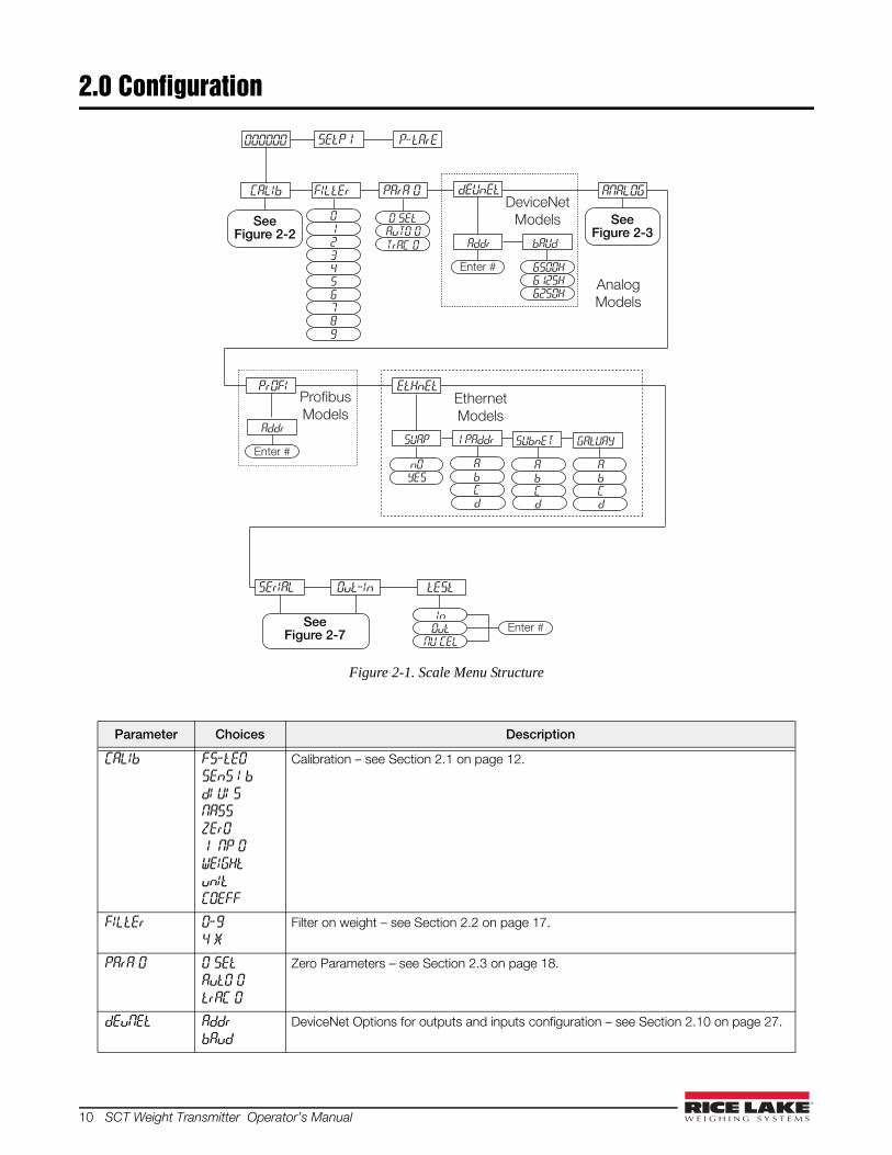
2.0 Configuration
Figure 2-1. Scale Menu Structure
Parameter Choices Description
CALIb FS-tEO
SEnS I b
dI UI S
NASS
ZErO
1 NP 0
WEIGHt
unIt
COEFF
Calibration – see Section 2.1 on page 12.
FILtEr 0-9
4 *
Filter on weight – see Section 2.2 on page 17.
PArA 0 0 SEt
AutO 0
trAC 0
Zero Parameters – see Section 2.3 on page 18.
dEuNEt Addr
bAud
DeviceNet Options for outputs and inputs configuration – see Section 2.10 on page 27.
CALIb FILtEr PArA 0 dEUnEt
0 SEtAuTO 0
TrAC 0 bAUdAddr
tEStOut-In
000000
2345
10
89
76
Enter #
6250H6125H6500H
InOut
NU CEL
Enter #
ANALOGDeviceNet
Models
P-tArESEtP1
SErIAL
PrOFI
Addr
Enter #
ProfibusModels
AnalogModels
EtHnEt
1 PAddrSUAP
YESnO
EthernetModels
SUbnET GAtUAY
CbA
dCbA
d
CbA
d
See Figure 2-2
See Figure 2-3
See Figure 2-7

Configuration 11
ANALOG tYPE
NOdE
ANA 0
ANA FS
COr 0
COr FS
Analog Options for outputs and inputs configuration – see Section 2.10 on page 27.
PrOFI Addr Profibus settings – see Section 2.6 on page 20.
EtHnEt SUAP
1 PAddr
SUbnEt
GAtUAY
SCT20-IP (EtherNet/IP) settings – see Section 2.7 on page 21.
SErIAL rS-485
bAud
Addr
HErtZ
dELAY
PArItY
StOP
Serial Communications settings – see Section 2.9 on page 24.
Out-In Out 1
Out 2
Out 3
In 1
In 2
Outputs and Inputs configuration – See Section 2.10 on page 27.
tESt In
Out
NU-CEL
Test – see Section 2.11 on page 29.
* - indicates default value.
Parameter Choices Description

12 SCT Weight Transmitter Operator’s Manual
2.1 Calibration
Figure 2-2. Calibration Menu Structure
Parameter Choices Description
FS-tEO Enter #0 =dENO *
System Full Scale is determined by multiplying one load cell capacity by the number of load cells used. Example of system full scale value calculation:
4 cells of 1000kg ----> FULL SCALE = 1000 X 4 = 4000
The instrument is supplied with a theoretical full scale value deno correspondingto 10000. To restore factory values, set 0 as full scale.
SEnSI b Enter #0.50000to7.00000
2.00000 *
Sensitivity is a load cell rated parameter expressed in mV/V. Set the average sensitivity value indicated on the load cells. Example of 4-cell system with sensitivity
2.00100, 2.00150, 2.00200, 2.00250; enter 2.00175,
calculated as (2.00100 + 2.00150 + 2.00200 + 2.00250) / 4.
dI UI S 1
2 *
5
10
20
50
100
0.0001
0.0002
0.0005
0.001
0.002
0.005
0.01
0.02
0.05
0.1
0.2
0.5
Division (resolution) - the weight increment (display division size) that the scale counts by.Selections are: 0.0001 and 100 with x1 x2 x5 x10 increments.
dI UI S
WEIGHt unIt COEFF
LItrE
bArAtN
PI ECE
nEUtonlb
OtHErHI LOG
HI LO-NnEU-N
Gt
FS-tEO
Enter #
SEnS Lb
Enter #
NASS
Enter #
ZErO
Enter #
Enter # Enter #
I NP 0
Enter #
50
1000.00010.0002
2010
0.0020.005
0.0010.0005
25
0.020.05
0.01
0.20.5
0.1
1
FILtEr PArA 0 SErIAL tEStOut-InANA LOG
000000 SEtP1
CALIb
PtArE
Note
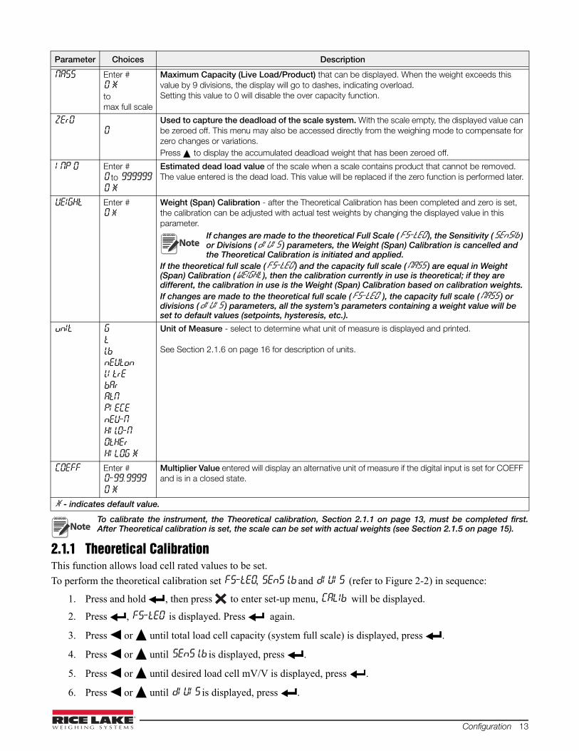
Configuration 13
To calibrate the instrument, the Theoretical calibration, Section 2.1.1 on page 13, must be completed first.After Theoretical calibration is set, the scale can be set with actual weights (see Section 2.1.5 on page 15).
2.1.1 Theoretical CalibrationThis function allows load cell rated values to be set.
To perform the theoretical calibration set FS-tEO, SEnS lb and dI UI S (refer to Figure 2-2) in sequence:
1. Press and hold , then press to enter set-up menu, CALIb will be displayed.
2. Press , FS-tEO is displayed. Press again.
3. Press or until total load cell capacity (system full scale) is displayed, press .
4. Press or until SEnS lb is displayed, press .
5. Press or until desired load cell mV/V is displayed, press .
6. Press or until dI UI S is displayed, press .
NASS Enter #0 *to max full scale
Maximum Capacity (Live Load/Product) that can be displayed. When the weight exceeds this value by 9 divisions, the display will go to dashes, indicating overload. Setting this value to 0 will disable the over capacity function.
ZErO0
Used to capture the deadload of the scale system. With the scale empty, the displayed value can be zeroed off. This menu may also be accessed directly from the weighing mode to compensate for zero changes or variations. Press to display the accumulated deadload weight that has been zeroed off.
I NP 0 Enter #0 to 999999
0 *
Estimated dead load value of the scale when a scale contains product that cannot be removed. The value entered is the dead load. This value will be replaced if the zero function is performed later.
UEIGHt Enter #0 *
Weight (Span) Calibration - after the Theoretical Calibration has been completed and zero is set, the calibration can be adjusted with actual test weights by changing the displayed value in this parameter.
If changes are made to the theoretical Full Scale (FS-tEO ), the Sensitivity (SEnSIb ) or Divisions (dI UI S ) parameters, the Weight (Span) Calibration is cancelled and the Theoretical Calibration is initiated and applied.
If the theoretical full scale (FS-tEO ) and the capacity full scale (NASS ) are equal in Weight (Span) Calibration (WEIGHt ), then the calibration currently in use is theoretical; if they are different, the calibration in use is the Weight (Span) Calibration based on calibration weights. If changes are made to the theoretical full scale (FS-tEO ), the capacity full scale (NASS ) or divisions (dI UI S ) parameters, all the system’s parameters containing a weight value will be set to default values (setpoints, hysteresis, etc.).
unIt G
t
lb nEUton
lI trE
bAr
AtN
PI ECE
nEU-N
HI lO-N
OtHEr
HI LOG *
Unit of Measure - select to determine what unit of measure is displayed and printed.
See Section 2.1.6 on page 16 for description of units.
COEFF Enter #0-99.9999
0 *
Multiplier Value entered will display an alternative unit of measure if the digital input is set for COEFF and is in a closed state.
* - indicates default value.
Parameter Choices Description
Note
Note

14 SCT Weight Transmitter Operator’s Manual
7. Press or until desired display division size is displayed, press .
8. This completes the Theoretical Calibration, press twice to exit set-up menu or continue to Section 2.1.2.
By modifying the theoretical full scale, the sensitivity or divisions, the Weight (Span) Calibration is cancelledand the Theoretical Calibration only is considered valid.
If the theoretical full scale and the recalculated full scale in Weight (Span) calibration (see Section 2.1.5 onpage 15) are equal, this means that the calibration currently in use is Theoretical Calibration; if they aredifferent, the calibration in use is the Weight (Span) Calibration based on test weights.
By modifying the theoretical full scale, the sensitivity or divisions and all the system’s parameters containing aweight value will be set to default values (setpoints, hysteresis, etc.).
2.1.2 Maximum Capacity (NASS )Maximum capacity (live load/product) that can be displayed. When the weight exceeds this value by 9 divisions
the following is displayed ‘------’, indicating overload. To disable this function, set to 0.
1. Press and hold , then press to enter set-up menu, CALIb will be displayed.
2. Press , FS-tEO is displayed.
3. Press or until NASS is displayed, press .
4. Press or until desired capacity is displayed, press .
5. Press twice to exit set-up menu.
2.1.3 Zero SettingPerform this procedure after having set the Theoretical calibration, see Section 2.1.1 on page 13.
This menu may also be accessed directly from the weight display, press and hold for 3 seconds.
1. Press and hold , then press to enter set-up menu, CALIb will be displayed.
2. Press , FS-tEO is displayed.
3. Press or until ZErO is displayed, press .
4. The weight value to be set to zero is displayed. In this phase all of the LEDs are flashing. Press , theweight is set to zero (the value is stored to the permanent memory).
5. Press twice to exit set-up menu.
Press to display the accumulated deadload that has been zeroed off by the instrument, displaying the sumof all of the previous zero settings.
2.1.4 Zero Value Manual EntryPerform this procedure only if it is not possible to zero off the scale structure, for example because itcontains product that can not be unloaded.
Enter the estimated structured dead load value that would be zeroed.1. Press and hold , then press to enter set-up menu, CALIb will be displayed.
2. Press , FS-tEO is displayed.
3. Press or until INP 0 is displayed, press .
4. Press or until desired dead load value is displayed, press .
5. Press twice to exit set-up menu.
Note
Note
Note
Important

Configuration 15
2.1.5 Weight (Span) Calibration (With Test Weights)After performing the Theoretical calibration (Section 2.1.1 on page 13) and the Zero setting (Section 2.1.3 on page14), this function allows calibration to be done using test weights of known value. If adjustment is required, changethe displayed value to display the test weight value.
1. Load the test weight onto the scale, use as high a percentage of the maximum quantity to be weighed aspossible.
2. Press and hold , then press to enter set-up menu, CALIb will be displayed.
3. Press , FS-tEO is displayed.
4. Press or until UEIGHt is displayed, press .
5. The value of the weight currently on the system will be flashing on the display. All of the LEDs are off. (Ifadjustment is not required, skip to step 8.)
6. Adjust the value on display to match weight loaded on the scale if necessary, by pressing or . TheLEDs will begin scrolling.
7. Press , the new set weight will appear with all the LEDs flashing.
8. Press , UEIGHt will be displayed again.
9. Press twice to exit set-up menu.
Example: For a system of maximum capacity of 1000 kg and 1 kg division, two test weights are available, one 500 kg and one 300 kg.Load both weights onto the system and correct the indicated weight to 800. Now remove the 300 kg weight, the systemmust show 500; remove the 500 kg weight, too; the system must read zero. If this does not happen, it means that there isa mechanical problem affecting the system linearity.
Identify and correct any mechanical problems before repeating the procedure.
If theoretical full scale and recalculated full scale in Weight (Span) Calibration are equal, it means that theTheoretical Calibration is currently in use; otherwise, the Weight (Span) Calibration based on test weights is inuse.
If the correction made changes the previous full scale for more than 20%, all the parameters with settableweight values are reset to default values.
Linearization Option On Max 5 Points:It is possible to perform a linearization of the weight repeating the above described procedure up to a maximum offive points, using five different test weights. The procedure ends by pressing or after entering the fifthvalue; at this point it will no longer be possible to change the calibration value, but only to perform a new Weight(Span) Calibration. To perform a new calibration, return to the weight display and then re-enter the calibrationmenu.
By pressing after having confirmed the test weight that has been set, the full scale appears, recalculatedaccording to the value of the maximum test weight entered and making reference to the cell sensitivity set in thetheoretical calibration (SEnSI b).
Important
Note

16 SCT Weight Transmitter Operator’s Manual
2.1.6 Setting Units of Measure1. Press and hold , then press to enter set-up menu, CALIb will be displayed.
2. Press , FS-tEO is displayed.
3. Press or until unIt is displayed, press .
4. Press or until desired unit is displayed, press .
5. Press twice to exit set-up menu.
* Indicates it is possible to set the display coefficient. To use COEFF it is necessary to enable it, closing the COEFFinput. See Section 2.1.7 on page 16.
If the print function is enabled, the symbol of the selected unit of measure will be printed after the measuredvalue.
2.1.7 Display CoefficientBy setting the coefficient the display is changed accordingly.
If one of the inputs is set to COEFF mode (see Section 2.10 on page 27) when the input is closed the value will bedisplayed modified according to the coefficient; when the input is opened the standard weight display will berestored.
1. Press and hold , then press to enter set-up menu, CALIb will be displayed.
2. Press , FS-tEO is displayed.
3. Press or until COEFF is displayed, press .
4. Press or until desired number is displayed, press .
5. Press twice to exit set-up menu.
All other settings (setpoints, hysteresis, calibration ...) are expressed in weight value. If you want toconvert them to the new unit of measurement, perform one of the following procedures for changing thesystem calibration.The parameter must remain set to 1.0000.
HI LOG kilograms LI tre litres*
G grams bAr bar*
t tons AtN atmospheres*
Lb pounds* PI ECE pieces*
nEUton newton* nEU-N newton metres*
LI tre litres* HI LO-N kikgram metres*
bAr bar* OtHEr units of measure not included*
HI LOG kilograms
G grams
t tons
Lb pounds Value set in COEFF will be multiplied by the weight value currently displayed
nEUton newton Value set in COEFF will be multiplied by the weight value currently displayed
LI trelitres in COEFF set the specific weight in kg/l, assuming that the system is
calibrated in kg
bAr bar Value set in COEFF will be multiplied by the weight value currently displayed
AtN atmospheres Value set in COEFF will be multiplied by the weight value currently displayed
PI ECE pieces in COEFF set the weight of one piece
nEU-N newton metres Value set in COEFF will be multiplied by the weight value currently displayed
HI LO-N kikgram metres Value set in COEFF will be multiplied by the weight value currently displayed
OtHErother generic units of measure not included in list
Value set in COEFF will be multiplied by the weight value currently displayed
Note
Important
Configuration 17
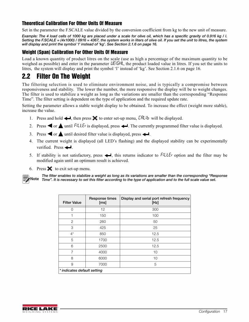
Theoretical Calibration For Other Units Of MeasureSet in the parameter the F.SCALE value divided by the conversion coefficient from kg to the new unit of measure.Example: The 4 load cells of 1000 kg are placed under a scale for olive oil, which has a specific gravity of 0.916 kg / l.Setting the F.SCALE = (4x1000) / 0916 = 4367, the system works in liters of olive oil. If you set the unit to litres, the systemwill display and print the symbol ‘l’ instead of ‘kg’. See Section 2.1.6 on page 16.
Weight (Span) Calibration For Other Units Of MeasureLoad a known quantity of product litres on the scale (use as high a percentage of the maximum quantity to beweighed as possible) and enter in the parameter UEIGHt, the product loaded value in litres. If you set the units tolitres, the system will display and print the symbol ‘l’ instead of ‘kg’. See Section 2.1.6 on page 16.
2.2 Filter On The WeightThe filtering selection is used to eliminate environment noise, and is typically a compromise betweenresponsiveness and stability. The lower the number, the more responsive the display will be to weight changes.The filter is used to stabilize a weight as long as the variations are smaller than the corresponding “ResponseTime”. The filter setting is dependent on the type of application and the required update rate.
Setting the parameter allows a stable weight display to be obtained. To increase the effect (weight more stable),increase the value.
1. Press and hold , then press to enter set-up menu, CALIb will be displayed.
2. Press or until FILtEr is displayed, press . The currently programmed filter value is displayed.
3. Press or until desired filter value is displayed, press .
4. The current weight is displayed (all LED’s flashing) and the displayed stability can be experimentally
verified. Press .
5. If stability is not satisfactory, press , this returns indicator to FILtEr option and the filter may bemodified again until an optimum result is achieved.
6. Press to exit set-up menu.
The filter enables to stabilize a weight as long as its variations are smaller than the corresponding “ResponseTime”. It is necessary to set this filter according to the type of application and to the full scale value set.
Filter ValueResponse times
[ms]Display and serial port refresh frequency
[Hz]
0 12 300
1 150 100
2 260 50
3 425 25
4* 850 12.5
5 1700 12.5
6 2500 12.5
7 4000 10
8 6000 10
9 7000 5
* indicates default setting
Note
18 SCT Weight Transmitter Operator’s Manual
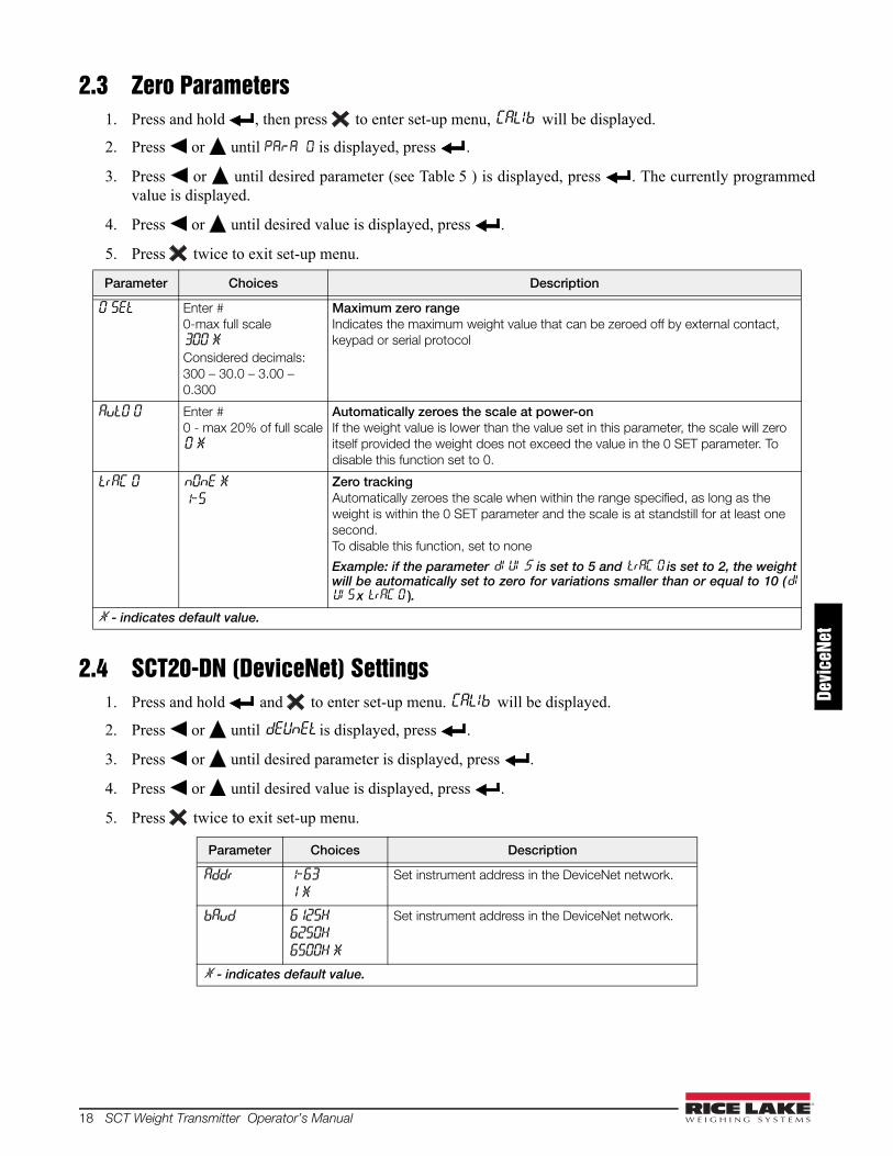
2.3 Zero Parameters1. Press and hold , then press to enter set-up menu, CALIb will be displayed.
2. Press or until is displayed, press .
3. Press or until desired parameter (see Table 5 ) is displayed, press . The currently programmedvalue is displayed.
4. Press or until desired value is displayed, press .
5. Press twice to exit set-up menu.
2.4 SCT20-DN (DeviceNet) Settings1. Press and hold and to enter set-up menu. CALIb will be displayed.
2. Press or until dEUnEt is displayed, press .
3. Press or until desired parameter is displayed, press .
4. Press or until desired value is displayed, press .
5. Press twice to exit set-up menu.
Parameter Choices Description
0 SEt Enter #0-max full scale300 *Considered decimals: 300 – 30.0 – 3.00 – 0.300
Maximum zero rangeIndicates the maximum weight value that can be zeroed off by external contact, keypad or serial protocol
AutO 0 Enter #0 - max 20% of full scale0 *
Automatically zeroes the scale at power-onIf the weight value is lower than the value set in this parameter, the scale will zero itself provided the weight does not exceed the value in the 0 SET parameter. To disable this function set to 0.
trAC 0 nOnE *
1-5
Zero trackingAutomatically zeroes the scale when within the range specified, as long as the weight is within the 0 SET parameter and the scale is at standstill for at least one second.To disable this function, set to none
Example: if the parameter dI UI S is set to 5 and trAC 0 is set to 2, the weightwill be automatically set to zero for variations smaller than or equal to 10 (dIUI S x trAC 0 ).
* - indicates default value.
Parameter Choices Description
Addr 1-63
1 *
Set instrument address in the DeviceNet network.
bAud 6125H
6250H
6500H *
Set instrument address in the DeviceNet network.
* - indicates default value.
Devi
ceNe
t
Configuration 19
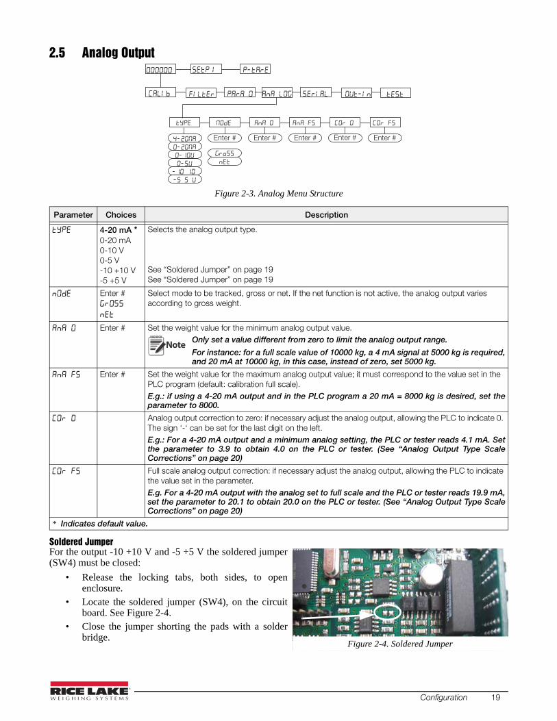
2.5 Analog Output
Figure 2-3. Analog Menu Structure
Soldered JumperFor the output -10 +10 V and -5 +5 V the soldered jumper(SW4) must be closed:
• Release the locking tabs, both sides, to openenclosure.
• Locate the soldered jumper (SW4), on the circuitboard. See Figure 2-4.
• Close the jumper shorting the pads with a solderbridge.
Parameter Choices Description
4-20 mA * 0-20 mA0-10 V0-5 V-10 +10 V-5 +5 V
Selects the analog output type.
See “Soldered Jumper” on page 19See “Soldered Jumper” on page 19
Enter #
Select mode to be tracked, gross or net. If the net function is not active, the analog output varies according to gross weight.
Enter # Set the weight value for the minimum analog output value.Only set a value different from zero to limit the analog output range.
For instance: for a full scale value of 10000 kg, a 4 mA signal at 5000 kg is required,and 20 mA at 10000 kg, in this case, instead of zero, set 5000 kg.
Enter # Set the weight value for the maximum analog output value; it must correspond to the value set in the PLC program (default: calibration full scale). E.g.: if using a 4-20 mA output and in the PLC program a 20 mA = 8000 kg is desired, set theparameter to 8000.
Analog output correction to zero: if necessary adjust the analog output, allowing the PLC to indicate 0. The sign ‘-‘ can be set for the last digit on the left. E.g.: For a 4-20 mA output and a minimum analog setting, the PLC or tester reads 4.1 mA. Setthe parameter to 3.9 to obtain 4.0 on the PLC or tester. (See “Analog Output Type ScaleCorrections” on page 20)
Full scale analog output correction: if necessary adjust the analog output, allowing the PLC to indicate the value set in the parameter. E.g. For a 4-20 mA output with the analog set to full scale and the PLC or tester reads 19.9 mA,set the parameter to 20.1 to obtain 20.0 on the PLC or tester. (See “Analog Output Type ScaleCorrections” on page 20)
* Indicates default value.
Enter # Enter # Enter # Enter #Enter #
Note
Figure 2-4. Soldered Jumper
20 SCT Weight Transmitter Operator’s Manual
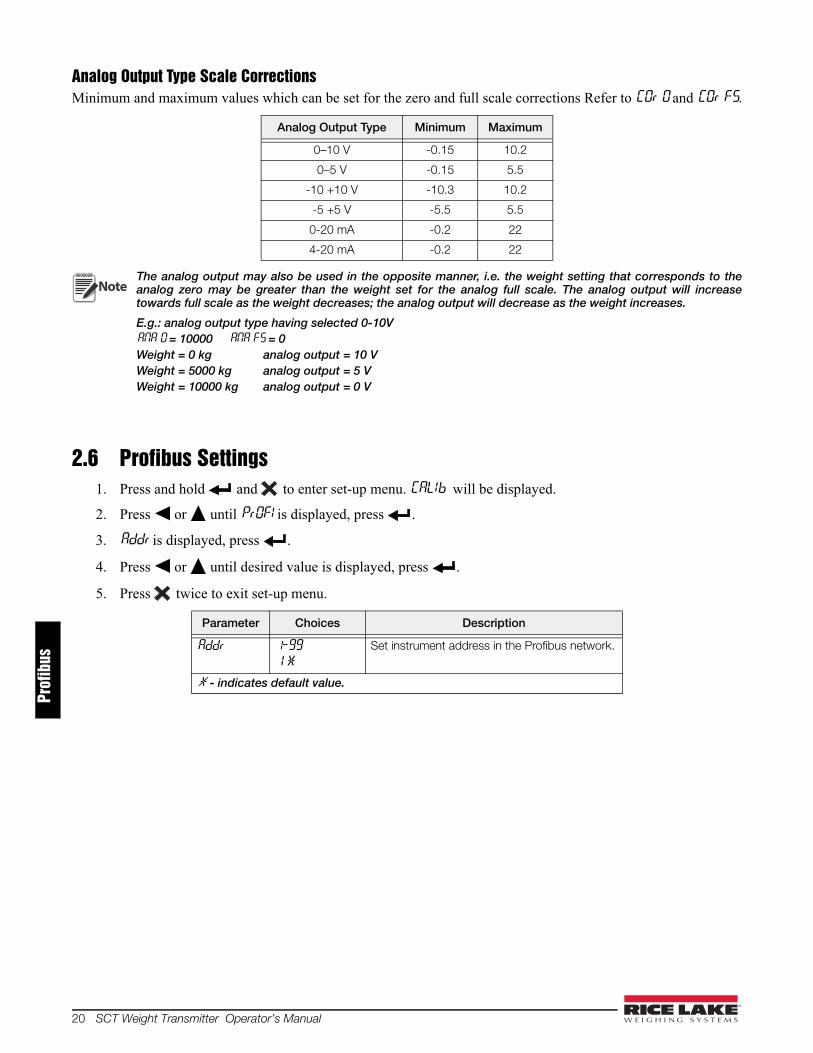
Analog Output Type Scale CorrectionsMinimum and maximum values which can be set for the zero and full scale corrections Refer to COr 0 and COr FS.
The analog output may also be used in the opposite manner, i.e. the weight setting that corresponds to theanalog zero may be greater than the weight set for the analog full scale. The analog output will increasetowards full scale as the weight decreases; the analog output will decrease as the weight increases.
E.g.: analog output type having selected 0-10VANA 0 = 10000 ANA FS = 0 Weight = 0 kg analog output = 10 VWeight = 5000 kg analog output = 5 VWeight = 10000 kg analog output = 0 V
2.6 Profibus Settings1. Press and hold and to enter set-up menu. CALIb will be displayed.
2. Press or until PrOFI is displayed, press .
3. Addr is displayed, press .
4. Press or until desired value is displayed, press .
5. Press twice to exit set-up menu.
Analog Output Type Minimum Maximum
0–10 V -0.15 10.2
0–5 V -0.15 5.5
-10 +10 V -10.3 10.2
-5 +5 V -5.5 5.5
0-20 mA -0.2 22
4-20 mA -0.2 22
Parameter Choices Description
Addr 1-99
1 *
Set instrument address in the Profibus network.
* - indicates default value.
Note
Prof
ibus
Configuration 21
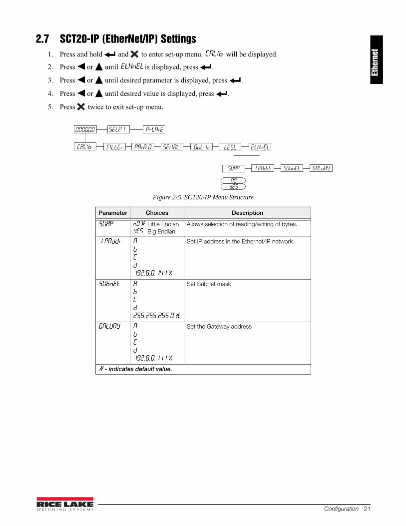
2.7 SCT20-IP (EtherNet/IP) Settings1. Press and hold and to enter set-up menu. CALIb will be displayed.
2. Press or until EtHnEt is displayed, press .
3. Press or until desired parameter is displayed, press .
4. Press or until desired value is displayed, press .
5. Press twice to exit set-up menu.
Figure 2-5. SCT20-IP Menu Structure
Parameter Choices Description
SUAP nO * Little EndianYES Big Endian
Allows selection of reading/writing of bytes.
1 PAddr A
b
C
d
192.8.0.141 *
Set IP address in the Ethernet/IP network.
SUbnEt A
b
C
d
255.255.255.0 *
Set Subnet mask
GAtUAY A
b
C
d
192.8.0.111 *
Set the Gateway address
* - indicates default value.
FILtEr PArA 0 SErIAL tEStOut-In EtHnEt
000000 P-tArESEtP1
CALIb
SUbnEt1 PAddr GAtuAY
NOYES
SUAP
Ethe
rnet
22 SCT Weight Transmitter Operator’s Manual
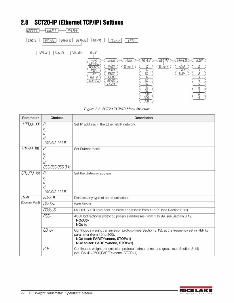
2.8 SCT20-IP (Ethernet TCP/IP) Settings
Figure 2-6. SCT20-TCP/IP Menu Structure
Parameter Choices Description
1 PAddr ** A
b
C
d
192.8.0.141 *
Set IP address in the Ethernet/IP network.
SUbnEt ** A
b
C
d
255.255.255.0 *
Set Subnet mask.
GAtUAY ** A
b
C
d
192.8.0.111 *
Set the Gateway address.
NodE(Comm Port)
nOnE * Disables any type of communication.
UEbSru Web Server
NOdbuS MODBUS-RTU protocol; possible addresses: from 1 to 99 (see Section 3.11)
ASCII ASCII bidirectional protocol; possible addresses: from 1 to 99 (see Section 3.12) NOdU6- NOd td
COntIn Continuous weight transmission protocol (see Section 3.13), at the frequency set in HERTZ parameter (from 10 to 300). NOd t(set: PARITY=none, STOP=1) NOd td(set: PARITY=none, STOP=1)
rI P Continuous weight transmission protocol, streams net and gross (see Section 3.14)(set: BAUD=9600,PARITY=none, STOP=1)
FILtEr PArA 0 SErIAL tEStOut-InEtHnEt
000000 P-tArESEtP1
CALIb
SUbnEt1 PAddr GAtuAY NodE
NOdbUSUEb5runOnE
HdrI PrIP
ASCII
HdrI Pn
AddrbAud HErt2 dELAY PArItY StOP
Enter #
96001920038400115200
48002400
30405060
2010
100200300
8070
Enter #
EUEnOddnOnE
2345
10
89
76

Configuration 23
Front Panel Configuration1. Press and hold and to enter set-up menu. CALIb will be displayed.
2. Press or until EtHnEt is displayed, press .
3. Press or until desired parameter is displayed, press .
4. Press or until desired value is displayed, press .
5. Press twice to exit set-up menu.
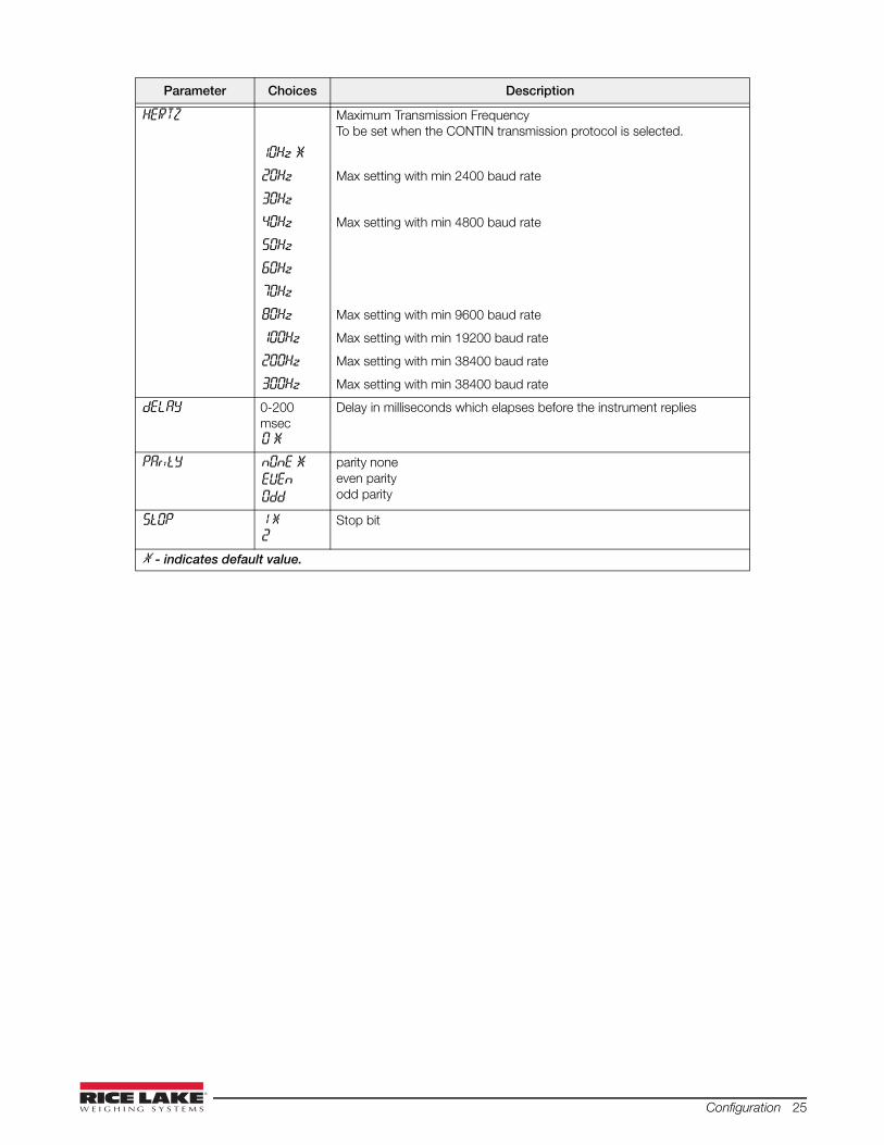
NodE(Continued)
Hdr1 P Continuous weight transmission protocol, streams net and gross including decimal. (see Section 3.14) (set: BAUD=9600,PARITY=none, STOP=1)
Hdr1 PN Continuous weight transmission protocol (see Section 3.14)(set: BAUD=9600,PARITY=none, STOP=1)When the remote display is set to gross weight:- if the instrument displays the gross weight, the remote display shows the gross weight.- if the instrument shows the net weight the remote display shows the net weight alternated with the message “net”
bAud 2400
4800
9600 *
19200
38400
115200
Transmission speed.
The baud rate must be the same as the baud rate setting in the Serial Communications Settings, see Section 2.9.
ADDR 1-99
1 *
Instruments address
HERTZ Maximum Transmission FrequencyTo be set when the CONTIN transmission protocol is selected. (see Figure 2-7)
10Hz *
20Hz Max setting with min 2400 baud rate
30Hz
40Hz Max setting with min 4800 baud rate
50Hz
60Hz
70Hz
80Hz Max setting with min 9600 baud rate
100Hz Max setting with min 19200 baud rate
200Hz Max setting with min 38400 baud rate
300Hz Max setting with min 38400 baud rate
dELAY 0-200 msec0 *
Delay in milliseconds which elapses before the instrument replies
PAritY nOnE *
EUEn
Odd
parity noneeven parityodd parity
StOP 1 *
2Stop bit
* - indicates default value.** - These settings do not function with Firmware 1.02.00 or lower.
Parameter Choices Description
Note

24 SCT Weight Transmitter Operator’s Manual
2.9 Serial Communication Settings
Figure 2-7. Serial Communications Menu Structure
Parameter Choices Description
rS-485(Communication Port)
nOnE * Disables any type of communication.
NOdbuS MODBUS-RTU protocol; possible addresses: from 1 to 99 (see Section 3.11)
ASCII ASCII bidirectional protocol; possible addresses: from 1 to 99 (see Section 3.12) NOdU6- NOd td
COntIn Continuous weight transmission protocol (see Section 3.13), at the frequency set in HERTZ parameter (from 10 to 300). NOd t(set: PARITY=none, STOP=1) NOd td(set: PARITY=none, STOP=1)
rI P Continuous weight transmission protocol, streams net and gross (see Section 3.14)(set: BAUD=9600,PARITY=none, STOP=1)
Hdr1 P Continuous weight transmission protocol, streams net and gross including decimal. (see Section 3.14) (set: BAUD=9600,PARITY=none, STOP=1)
Hdr1 PN Continuous weight transmission protocol (see Section 3.14)(set: BAUD=9600,PARITY=none, STOP=1)When the remote display is set to gross weight:- if the instrument displays the gross weight, the remote display showsthe gross weight.- if the instrument shows the net weight the remote display shows the net weight alternated with the message “net”
bAud 2400
4800
9600 *
19200
38400
115200
Transmission speed.
ADDR 1-99
1 *
Instruments address
rS485
nOnENodbUSASCII
Cont In
rI PHdrI PHdrI Pn
CALIb FILtEr PArA 0 SErIAL tEStOut-InANA LOG
AddrbAud HErt2 dELAY PArItY StOP
Enter #
96001920038400115200
48002400
30405060
2010
100200300
8070
Enter #
EUEnOddnOnE
2345
10
89
76
Configuration 25
HERTZ Maximum Transmission FrequencyTo be set when the CONTIN transmission protocol is selected.
10Hz *
20Hz Max setting with min 2400 baud rate
30Hz
40Hz Max setting with min 4800 baud rate
50Hz
60Hz
70Hz
80Hz Max setting with min 9600 baud rate
100Hz Max setting with min 19200 baud rate
200Hz Max setting with min 38400 baud rate
300Hz Max setting with min 38400 baud rate
dELAY 0-200 msec0 *
Delay in milliseconds which elapses before the instrument replies
PAritY nOnE *
EUEn
Odd
parity noneeven parityodd parity
StOP 1 *
2Stop bit
* - indicates default value.
Parameter Choices Description
26 SCT Weight Transmitter Operator’s Manual
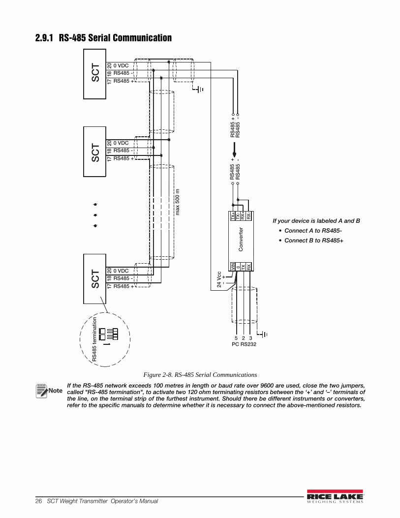
2.9.1 RS-485 Serial Communication
Figure 2-8. RS-485 Serial Communications
If the RS-485 network exceeds 100 metres in length or baud rate over 9600 are used, close the two jumpers,called "RS-485 termination", to activate two 120 ohm terminating resistors between the ‘+’ and ‘–’ terminals ofthe line, on the terminal strip of the furthest instrument. Should there be different instruments or converters,refer to the specific manuals to determine whether it is necessary to connect the above-mentioned resistors.
8171
8171
8171
SC
TS
CT
SC
T
RS
485
+R
S48
5 -
max
500
m
RS485 +
RS485 -
PC RS232
RX
+
RX
-
TX
-T
X+
Co
nver
ter
24 V
cc +
-
0 TX
RX
VIN
RS
485
+R
S48
5 -
RS
485
term
inat
ion
2020
0 VDC20
RS485 +
RS485 -0 VDC
RS485 +
RS485 -0 VDC
5 2 3
If your device is labeled A and B
• Connect A to RS485-
• Connect B to RS485+
Note
Configuration 27
Direct Connection Between RS-485 And RS-232 Without ConverterSince a two-wire RS-485 output may be used directly on the RS-232 input of a PC or remote display, it is possibleto implement instrument connection to an RS-232 port in the following manner:
This type of connection allows a SINGLE instrument to be used in a ONE WAY mode.
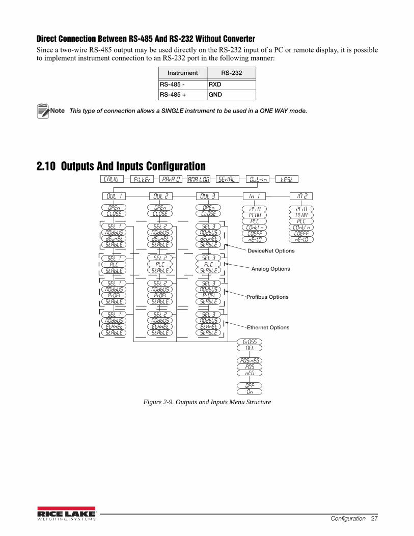
2.10 Outputs And Inputs Configuration
Figure 2-9. Outputs and Inputs Menu Structure
Instrument RS-232
RS-485 - RXD
RS-485 + GND
Note
OUt 1 OUt 2 OUt 3 In 1 IN 2
CLOSEOPEn
SEt 1NOdbUS
StAbLE
GrOSSNEt
dEunEt
2ErOPEAH
COntI nPLC
nE-lOCOEFF
2Er0PEAH
COntI nPLC
nE-lOCOEFF
CLOSEOPEn
SEt 2NOdbUS
StAbLEdEunEt
CLOSEOPEn
SEt 3NOdbUS
StAbLE
POS/nEGPOSnEG
dEunEt
OFFOn
CALIb FILtEr PArA 0 SErIAL tEStOut-InANA LOG
DeviceNet Options
SEt 1
StAbLEPLC
SEt 2
StAbLEPLC
SEt 3
StAbLEPLC
Analog Options
SEt 1NOdbUS
StAbLEPrOFI
SEt 2NOdbUS
StAbLEPrOFI
SEt 3NOdbUS
StAbLEPrOFI
SEt 1NOdbUS
StAbLEEtHnEt
SEt 2NOdbUS
StAbLEEtHnEt
SEt 3NOdbUS
StAbLEEtHnEt
Profibus Options
Ethernet Options

28 SCT Weight Transmitter Operator’s Manual
Parameter Choices Description
OUt 1
OUt 2
OUt 3
OPEn Normally Open: the relay is de-energized and the contact is open when the weight is lower than the programmed setpoint value; it closes when the weight is higher than or equal to the programmed setpoint value.
CLOSE * Normally closed: the relay is energized and the contact is closed when the weight is lower than the programmed setpoint value; it opens when the weight is higher than or equal to the programmed setpoint value.
OUt 1
OUt 2
OUt 3
SEt 1
SEt 2
SEt 3
Number corresponds with OUT 1, 2 or 3.The contact will switch on the basis of weight, according to setpoints (see Section 2.12 “Setpoints Programming” on page 30) Select:Gross (default) - the contact will switch on the basis of gross weight orNet - the contact will switch on the basis of net weight (If the net function is not active, the contact will switch on the basis of gross weight).
NOdbUS The contact will not switch on the basis of weight, but is controlled by remote Modbus protocol commands. (DeviceNet, Profibus, Ethernet Only)
dEunEt The contact will not switch on the basis of weight, but is controlled by DeviceNet. (DeviceNet Model Only)
PrOFI The contact will not switch on the basis of weight, but is controlled by Profibus. (Profibus Model Only)
EtHnEt The contact will not switch on the basis of weight, but is controlled by Ethernet. (Ethernet Model Only)
PLC The contact will not switch on the basis of weight, but is controlled by remote protocol commands. (Analog Only)
StAbLE Relay switching occurs when the weight is stable.
SEt 1
SEt 2
SEt 3
POSnEG * Relay switching occurs for both positive and negative weight values.
POS Relay switching occurs for positive weight values only.
NEG Relay switching occurs for negative weight values only.
SEt 1
SEt 2
SEt 3
OFF * Relay switching will not occur if the setpoint value is ‘0’.
On Setpoint = ’0’ and nodbus=posneg, relay switching occurs when the weight is ‘0’; the relay will switch again when the weight is different from zero, taking hysteresis into account (both for positive and for negative weights).
Setpoint = ’0’ and nodes=pos, relay switching occurs for a weight higher than or equal to ‘0’, the relay will switch again for values below ‘0’, taking hysteresis into account.
Setpoint = ’0’ and nodes=neg, relay switching occurs for a weight lower than or equal to ‘0’, the relay will switch again for values above ‘0’, taking hysteresis into account.
In 1
In 2
nE-LO *(In 2 default)
(NET/GROSS): by closing this input for less than one second, it performs a SEMI-AUTOMATIC TARE and the display will show the net weight. To display the gross weight again, hold the NET/GROSS input closed for 3 seconds.
2ErO *(In 1 default)
By closing the input for less than one second, the weight is set to zero (see Section 3.3 “Semi-automatic Zero (Weight Zero-setting For Small Variations)” on page 33)
PEAH With the input closed the maximum weight value reached remains on display. Opening fthe input the current weight is displayed.
PLC Closing the input no operation is performed, the input status may however be read remotely by way of the communication protocol.
COntIn Closing the input for less than one second the weight is transmitted via the serial connection according to the fast continuous transmission protocol one time only (only if contin is set in the item serial).
COEFF When the input is closed the weight is displayed based on the set coefficient (see Section 2.1.7 “Display Coefficient” on page 16), otherwise the weight is displayed.
* - indicates default value.

Configuration 29
2.11 Test1. Press and hold and to enter set-up menu. CALIb will be displayed.
2. Press or until tEst is displayed, press .
3. Press or until desired parameter is displayed, press .
4. For In and NU-CEL, current reading is displayed, press .
For Out, press until corresponding value of the out you want to change is flashing, press to change
the value, press .
5. Press twice to exit set-up menu.
Parameter Choices Description
In N/A Input Test - for each open input 0 is displayed, 1 is displayed when the input is closed.
Out 0 *
1
Output Test - Setting 0 opens the corresponding output . Setting 1 closes the corresponding output .
ANALOG ANALOG Allows the analog signal to range between the minimum and the maximum values starting from the minimum.
NA Current output test
UOLt voltage output test
NU-CEL N/A Millivolt Test - displays the load cell response signal in mV with four decimals.
* - indicates default value.

30 SCT Weight Transmitter Operator’s Manual
2.12 Setpoints Programming1. Press to enter setpoints and hysteresis settings.
2. Press or until desired setpoint or hysteresis parameter is displayed, press to enter.
3. Press or until desired value is displayed, press to confirm.
4. Press to exit setpoints and hysteresis settings.
These values are set to zero if the calibration is changed significantly (see Section 2.1.1 “TheoreticalCalibration” on page 13 and Section 2.1.5 “Weight (Span) Calibration (With Test Weights)” on page 15).
Parameter Choices Description
SEtP 1
SEtP 2
SEtP 3
0-Full Scale0 *
Setpoint; relay switching occurs when the weight exceed the value set in this parameter. The type of switching is settable (see Section 2.10 “Outputs And Inputs Configuration” on page 27).
HYStE 1
HYStE 2
HYStE 3
0-Full Scale0 *
Hysteresis, value to be subtracted from the setpoint to obtain contact switching for decreasing weight. For example with a setpoint at 100 and hysteresis at 10, the switching occurs at 90 for decreasing weight.
* - indicates default value.
Note

Configuration 31
2.13 Reserved For The Installer2.13.1Menu LockingThrough this procedure, it is possible to block the access to any menu on the instrument.
1. Press and hold then press to enter set-up menu.
2. Press or until menu to be locked is displayed.
3. Press , and simultaneously for 3 seconds, the display shows C.ALIb (a decimal point appearsbetween the first and second letter that indicates this menu is now locked). If the operator tries to enter thismenu, access is denied and the display reads bLOC.
2.13.2Menu Unlocking1. Press and hold then press to enter set-up menu.
2. Press or until menu to be un-locked is displayed.
3. Press , and simultaneously for 3 seconds, the display shows CALIb (the decimal point betweenthe first and second letter is gone indicating the menu is un-locked).
2.13.3Temporary Menu Unlocking1. Press and hold then press to enter set-up menu.
2. Press or until menu to be temporarily un-locked is displayed.
3. Press and simultaneously for 3 seconds, the display shows CALIb (the decimal point between the firstand second letter is gone indicating the menu is un-locked).
4. It is now possible to enter and modify all menus including those which are locked. By returning to theweight display, the menu lock is restored.
2.13.4Default Scale
Operation must only be performed after contacting technical assistance
1. With power off, press and hold , then power on. Display shows PrOG .
2. Press , bASE is displayed.
3. Press , PASSU is displayed.
4. Press , 000000 is displayed.
5. Press and to enter 6935.
6. Press , UAIt is displayed.
7. Instrument will reboot.
By confirming the displayed program, the system variables are set to default values.
Important
Note
32 SCT Weight Transmitter Operator’s Manual
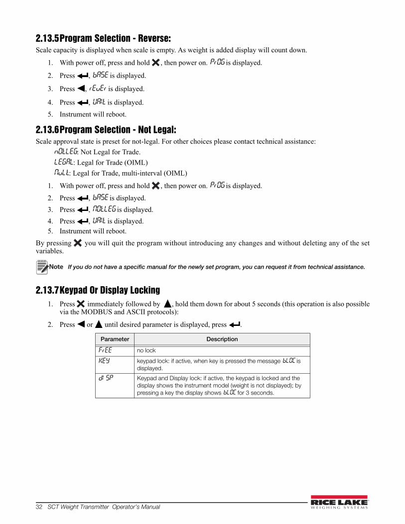
2.13.5Program Selection - Reverse:Scale capacity is displayed when scale is empty. As weight is added display will count down.
1. With power off, press and hold , then power on. PrOG is displayed.
2. Press , bASE is displayed.
3. Press , rEuEr is displayed.
4. Press , UAIt is displayed.
5. Instrument will reboot.
2.13.6Program Selection - Not Legal:Scale approval state is preset for not-legal. For other choices please contact technical assistance:
nOtLEG: Not Legal for Trade.
LEGAL: Legal for Trade (OIML)
NuLt: Legal for Trade, multi-interval (OIML)
1. With power off, press and hold , then power on. PrOG is displayed.
2. Press , bASE is displayed.
3. Press , NOtLEG is displayed.
4. Press , UAIt is displayed.5. Instrument will reboot.
By pressing you will quit the program without introducing any changes and without deleting any of the setvariables.
If you do not have a specific manual for the newly set program, you can request it from technical assistance.
2.13.7Keypad Or Display Locking1. Press immediately followed by , hold them down for about 5 seconds (this operation is also possible
via the MODBUS and ASCII protocols):
2. Press or until desired parameter is displayed, press .
Parameter Description
FrEE no lock
KEY keypad lock: if active, when key is pressed the message bLOC is displayed.
dI SP Keypad and Display lock: if active, the keypad is locked and the display shows the instrument model (weight is not displayed); by pressing a key the display shows bLOC for 3 seconds.
Note

Operation 33
3.0 Operation3.1 Semi-automatic Tare (Net/Gross)
The semi-automatic tare value is lost upon instrument power-off.
The semi-automatic tare operation is not allowed if the gross weight is zero.
1. To capture tare and weigh in net mode (SEMI-AUTOMATIC TARE), close the NET/GROSS input orpress for 3 seconds. The instrument displays the net weight (zero) and the NET LED lights up.
2. To display the gross weight again, keep the NET/GROSS input closed or press for 3 seconds.
3. This operation can be repeated by the operator to allow the loading of several products.
Press and hold to display the gross weight temporarily. When is released, the net weight will bedisplayed again.
3.2 Preset Tare (Subtractive Tare Device)It is possible to manually set a preset tare value to be subtracted from the display value provided that the P-tArE ≤max capacity.
1. Press and hold and to display P-tArE, press .
2. Press or until desired value is displayed, press .
3. Press to exit P-tArE.
4. After setting the tare value, go back to the weight display, the display shows the net weight (subtracting thepreset tare value) and the NET LED lights up to show that a tare has been entered.
Press and hold for 3 seconds to display the gross weight temporarily. When is released, the net weightwill be displayed again.
To delete a preset tare and return to the gross weight display:
1. Press hold for 3 seconds or keep the NET/GROSS input (if any) closed for the same length of time (3seconds). The preset tare value is set to zero. The NET LED is turned off when the gross weight isdisplayed once again.
If a semi-automatic tare (net) is entered, it is not possible to access the enter preset tare function.
If a preset tare is entered, it is still possible to access the semiautomatic tare (net) function. The two differenttypes of tare are added.
All the semi-automatic tare (net) and preset tare functions will be lost when the instrument is turned off.
3.3 Semi-automatic Zero (Weight Zero-setting For Small Variations)By closing the SEMI-AUTOMATIC ZERO input, the weight is set to zero. The zero setting will be lost when theinstrument is turned off.
This function is only allowed if the weight is lower than the 0 set value (see 0 SET in Section 2.3 on page 18),otherwise the t----- alarm appears and the weight is not set to zero.
3.4 PeakBy keeping the input closed the maximum weight value reached remains displayed. Opening the input the currentweight is displayed.
If you wish to use this input to view a sudden variation peak, set the FILTER ON THE WEIGHT to 0.
Note
Note
Note
Note
Note

34 SCT Weight Transmitter Operator’s Manual
3.5 Alarms
DeviceNet Error (DeviceNet Models Only): A problem in the DeviceNet communication is marked by a lack offlashing or a slow flashing (duration about 0.5 s) of the DeviceNet status LED.
Profibus Error (Profibus Models Only): A problem in the Profibus communication is marked by a lack offlashing or a slow flashing (duration about 0.5 s) of the Profibus status LED.
Ethernet Error (Ethernet Models Only): A problem in the Ethernet communication is marked by a slowflashing (duration about 0.5 s) of the Ethernet status LED.
Modbus/TCP Error (Modbus/TCP Models Only): A problem in the Modbus/TCP communication is marked bya slow flashing (duration about 0.5 s) of the Modbus/TCP status LED.
* For RIP remote displays, if the message exceeds 5 digits the display reads ------.
In case of alarm the relays, not managed by Modbus, Modbus/TCP or DeviceNet, open.
In Analog Models only, if an alarm becomes active the relays open and the analog outputs go to the lowestpossible value according to the following table:
Display Description
ErCELLoad cell is not connected or is incorrectly connected; the load cell signal exceeds 39 mV; the conversion electronics (A/D converter) is malfunctioning; the load cell is a 4-wire and there are no jumpers between EX- and REF- and between EX+ and REF+.
Er OL Weight display exceeds 110% of the full scale.
Er Ad Internal instrument converter failure; check load cell connections, if necessary contact Technical Assistance.
--------- The weight exceeds the maximum weight by 9 divisions.
Er OF Maximum displayable value exceeded (value higher than 999999 or lower than -999999).
t------ Weight too high: zero setting not possible.
NAH-PUThis message appears in the test weight setting, in Weight (Span) Calibration, after the fifth test weight value has been entered.
Err0r
The value set for the parameter is beyond the permitted values; press to quit the setting mode leaving the previous value unchanged.
Example: a number of decimals is selected for full scale which exceeds the instrument's display potential;value above the maximum setting value; the weight value set in test weight verification does not match thedetected mV increase.
bLOC Lock is active on menu item, keypad or display.
nOdl SP It’s not possible to display the number properly because it is greater than 999999 or less than -999999.
Table 3-1. Alarm Descriptions
MODE ErCEL Er OL Er Ad --------- Er OF t-----
Bit LSB 76543210 xxxxxxx1
76543210 xxxx1xxx
76543210 xxxxxx1x
76543210 xxxxx1xx
76543210 On gross: xxx1xxxx On net: xx1xxxxx
The response to the zero command is a 'value not valid' error (error code 3)
Status Register MODBUS RTU
ASCII __O-F_ __O-L_ __O-F_ __O-L_ __O-F_ &aa#CR
RIP * __O-F_ __O-L_ __O-F_ __O-L_ __O-F_ __O-F_
HDRIP-N _ERCEL _ER_OL _ER_AD ###### _ER_OF O__SET
CONTIN _ERCEL _ER_OL _ER_AD ^^^^^^ _ER_OF O__SET
Table 3-2. Serial Protocols Alarms
Range 0/20mA 4/20 mA 0/5 V 0/10 V -10/10 V -5/5 VOutput Value
-0.2 mA 3.5 mA -0.5 V -0.5 V 0 V 0 V
Note
Operation 35
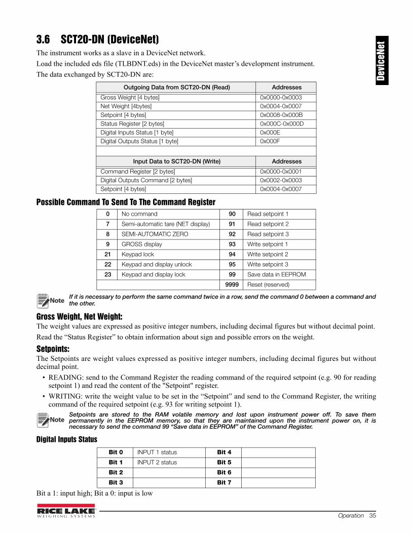
3.6 SCT20-DN (DeviceNet)The instrument works as a slave in a DeviceNet network.
Load the included eds file (TLBDNT.eds) in the DeviceNet master’s development instrument.
The data exchanged by SCT20-DN are:
Possible Command To Send To The Command Register
If it is necessary to perform the same command twice in a row, send the command 0 between a command andthe other.
Gross Weight, Net Weight:The weight values are expressed as positive integer numbers, including decimal figures but without decimal point.
Read the “Status Register” to obtain information about sign and possible errors on the weight.
Setpoints:The Setpoints are weight values expressed as positive integer numbers, including decimal figures but withoutdecimal point.
• READING: send to the Command Register the reading command of the required setpoint (e.g. 90 for readingsetpoint 1) and read the content of the "Setpoint" register.
• WRITING: write the weight value to be set in the “Setpoint” and send to the Command Register, the writingcommand of the required setpoint (e.g. 93 for writing setpoint 1).
Setpoints are stored to the RAM volatile memory and lost upon instrument power off. To save thempermanently in the EEPROM memory, so that they are maintained upon the instrument power on, it isnecessary to send the command 99 “Save data in EEPROM” of the Command Register.
Digital Inputs Status
Bit a 1: input high; Bit a 0: input is low
Outgoing Data from SCT20-DN (Read) Addresses
Gross Weight [4 bytes] 0x0000-0x0003 Net Weight [4bytes] 0x0004-0x0007 Setpoint [4 bytes] 0x0008-0x000B Status Register [2 bytes] 0x000C-0x000D Digital Inputs Status [1 byte] 0x000E Digital Outputs Status [1 byte] 0x000F
Input Data to SCT20-DN (Write) Addresses
Command Register [2 bytes] 0x0000-0x0001 Digital Outputs Command [2 bytes] 0x0002-0x0003 Setpoint [4 bytes] 0x0004-0x0007
0 No command 90 Read setpoint 1
7 Semi-automatic tare (NET display) 91 Read setpoint 2
8 SEMI-AUTOMATIC ZERO 92 Read setpoint 3
9 GROSS display 93 Write setpoint 1
21 Keypad lock 94 Write setpoint 2
22 Keypad and display unlock 95 Write setpoint 3
23 Keypad and display lock 99 Save data in EEPROM
9999 Reset (reserved)
Bit 0 INPUT 1 status Bit 4
Bit 1 INPUT 2 status Bit 5
Bit 2 Bit 6
Bit 3 Bit 7
Note
Note
Devi
ceNe
t
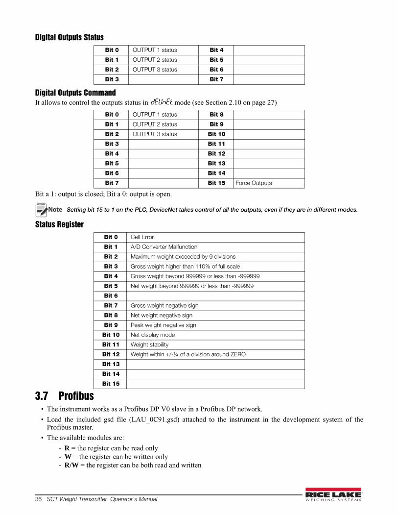
36 SCT Weight Transmitter Operator’s Manual
Digital Outputs Status
Digital Outputs CommandIt allows to control the outputs status in dEUnEt mode (see Section 2.10 on page 27)
Bit a 1: output is closed; Bit a 0: output is open.
Setting bit 15 to 1 on the PLC, DeviceNet takes control of all the outputs, even if they are in different modes.
Status Register
3.7 Profibus• The instrument works as a Profibus DP V0 slave in a Profibus DP network.
• Load the included gsd file (LAU_0C91.gsd) attached to the instrument in the development system of theProfibus master.
• The available modules are:
- R = the register can be read only - W = the register can be written only - R/W = the register can be both read and written
Bit 0 OUTPUT 1 status Bit 4
Bit 1 OUTPUT 2 status Bit 5
Bit 2 OUTPUT 3 status Bit 6
Bit 3 Bit 7
Bit 0 OUTPUT 1 status Bit 8
Bit 1 OUTPUT 2 status Bit 9
Bit 2 OUTPUT 3 status Bit 10
Bit 3 Bit 11
Bit 4 Bit 12
Bit 5 Bit 13
Bit 6 Bit 14
Bit 7 Bit 15 Force Outputs
Bit 0 Cell Error
Bit 1 A/D Converter Malfunction
Bit 2 Maximum weight exceeded by 9 divisions
Bit 3 Gross weight higher than 110% of full scale
Bit 4 Gross weight beyond 999999 or less than -999999
Bit 5 Net weight beyond 999999 or less than -999999
Bit 6
Bit 7 Gross weight negative sign
Bit 8 Net weight negative sign
Bit 9 Peak weight negative sign
Bit 10 Net display mode
Bit 11 Weight stability
Bit 12 Weight within +/-¼ of a division around ZERO
Bit 13
Bit 14
Bit 15
Note
Operation 37
GROSS WEIGHT – NET WEIGHT – PEAKThe weight values are expressed as positive integer numbers, include decimal figures but without decimal point.
Read the “Status Register” to obtain information about sign and possible errors on the weight.
To find out the decimal figures use the Division module value; E.g.: the net weight is 100000 and the division is0.001 (three decimals), the real weight value is 100.000kg
Setpoints – HysteresisThe weight values are expressed as positive integer numbers, include decimal figures but without decimal point.
• to set the value to 0; write the hexadecimal value hex 80000000 to the register (the most significant bit is 1 andall the other bits are 0).
• to set them correctly consider the module Division value; E.g. if you want to set a set-point to 100kg and theverification division value is 0.001, set the set-point value to 100000 (you remove the decimal points from thevalue that would be 100.000 with decimals).
• If from PLC you set a value out of the permitted interval (from 0 (not included) to full scale) the value isignored and the bit 13 “Writing error” rises in the “Status Register”.
Setpoints and Hysteresis are stored to the RAM volatile memory and lost upon instrument power off. To savethem permanently in the EEPROM memory, so that they are maintained upon the instrument power on, it isnecessary to send the command 99 “Save data in EEPROM” of the Command Register.
Divisions And Units Measure Registry (40014)This register contains the current setting of the divisions (parameter dI UI S) and of the units of measure (UnItparameter).
Use this register together with the coefficient registers to calculate the value displayed by the instrument.
MODULE Saving to EEPROMN. Byte
RN. Byte
WACCES
S
GROSS WEIGHT) 4 R
NET WEIGHT 4 R
PEAK WEIGHT 4 R
SETPOINT 1
Only after command ‘99’ of the
COMMAND REGISTER
4 4 R/W
SETPOINT 2 4 4 R/W
SETPOINT 3 4 4 R/W
HYSTERESIS 1 4 4 R/W
HYSTERESIS 2 4 4 R/W
HYSTERESIS 3 4 4 R/W
Divisions and Units of measure
2 R
Visualization Coefficient 4 R
INPUTS 2 R
OUTPUTS NO 2 2 R/W
STATUS REGISTER 2 R
COMMAND REGISTER NO 2 W
Sample Weight for calibration
Use with command ‘101’ of the COMMAND REGISTER
4 4 R/W
H Byte L Byte
Units of measure division
Note
Prof
ibus
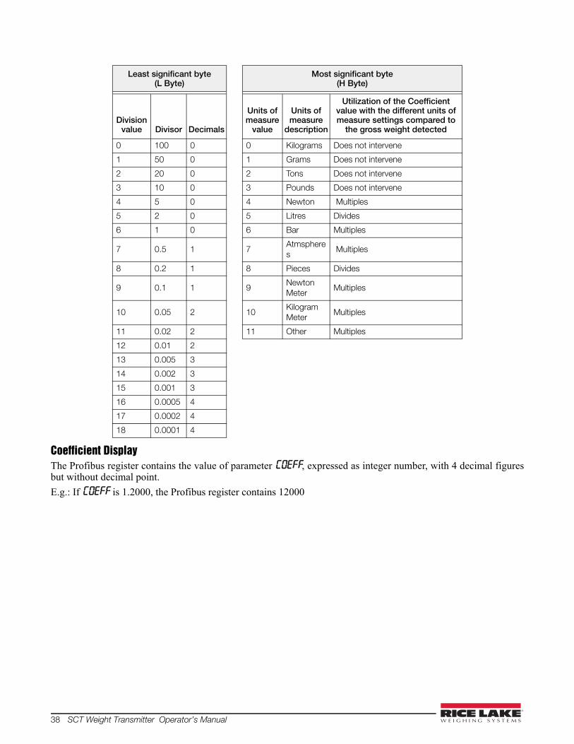
38 SCT Weight Transmitter Operator’s Manual
Coefficient DisplayThe Profibus register contains the value of parameter COEFF, expressed as integer number, with 4 decimal figuresbut without decimal point.
E.g.: If COEFF is 1.2000, the Profibus register contains 12000
Least significant byte(L Byte)
Most significant byte(H Byte)
Division value Divisor Decimals
Units of measure
value
Units of measure
description
Utilization of the Coefficient value with the different units of measure settings compared to
the gross weight detected
0 100 0 0 Kilograms Does not intervene
1 50 0 1 Grams Does not intervene
2 20 0 2 Tons Does not intervene
3 10 0 3 Pounds Does not intervene
4 5 0 4 Newton Multiples
5 2 0 5 Litres Divides
6 1 0 6 Bar Multiples
7 0.5 1 7Atmspheres
Multiples
8 0.2 1 8 Pieces Divides
9 0.1 1 9Newton Meter
Multiples
10 0.05 2 10Kilogram Meter
Multiples
11 0.02 2 11 Other Multiples
12 0.01 2
13 0.005 3
14 0.002 3
15 0.001 3
16 0.0005 4
17 0.0002 4
18 0.0001 4
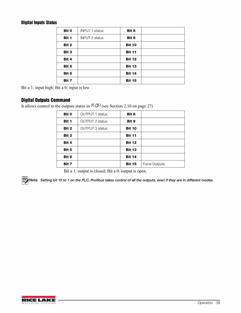
Operation 39
Digital Inputs Status
Bit a 1: input high; Bit a 0: input is low
Digital Outputs CommandIt allows control to the outputs status in PrOFI (see Section 2.10 on page 27)
Bit a 1: output is closed; Bit a 0: output is open.
Setting bit 15 to 1 on the PLC, Profibus takes control of all the outputs, even if they are in different modes.
Bit 0 INPUT 1 status Bit 8
Bit 1 INPUT 2 status Bit 9
Bit 2 Bit 10
Bit 3 Bit 11
Bit 4 Bit 12
Bit 5 Bit 13
Bit 6 Bit 14
Bit 7 Bit 15
Bit 0 OUTPUT 1 status Bit 8
Bit 1 OUTPUT 2 status Bit 9
Bit 2 OUTPUT 3 status Bit 10
Bit 3 Bit 11
Bit 4 Bit 12
Bit 5 Bit 13
Bit 6 Bit 14
Bit 7 Bit 15 Force Outputs
Note

40 SCT Weight Transmitter Operator’s Manual
Status Register
Bit 13 (writing error) rises if the PLC tries to write a value out of a parameter’s permitted interval. In this case thewriting has no effect and the previous parameter value is maintained.
Possible Command To Send To The Command Register
Commands are sent only once; to reassert it write the value 0 to the Command register and then the commandagain
Real Calibration Commands (With Sample Weight)The instrument calibration can be changed via PROFIBUS.
To correctly set the sample weight, consider the value of the division module (e); e.g. if you want to set the value to100kg and the division value is 0.001, set the register value to 100000 (you remove the decimal points form thevalue that would be 100.000 with decimals).
To perform the edit calibration procedure, it needs to unload the system and zero-setting the displayed weight valuewith the command 100 “Zero-setting for calibration” of Command Register. Then, put a sample weight onto thesystem, write the correct known weight value to the “Sample Weight for calibration” register; to save in memorythe sample weight value, send the command 101 “Sample weight storage for calibration”.
Bit 0 Cell Error
Bit 1 A/D Converter Malfunction
Bit 2 Maximum weight exceeded by 9 divisions
Bit 3 Gross weight higher than 110% of full scale
Bit 4 Gross weight beyond 999999 or less than -999999
Bit 5 Net weight beyond 999999 or less than -999999
Bit 6
Bit 7 Gross weight negative sign
Bit 8 Net weight negative sign
Bit 9 Peak weight negative sign
Bit 10 Net display mode
Bit 11 Weight stability
Bit 12 Weight within +/-¼ of a division around ZERO
Bit 13 Writing error
Bit 14
Bit 15
0 No command 17 Reserved
7 NET display 18 Reserved
8 SEMI-AUTOMATIC ZERO 21 Keypad lock
10 Reserved 22 Keypad and display unlock
11 Reserved 23 Keypad and display lock
12 Reserved 99 Save data in EEPROM
13 Reserved 100 Zero-setting for calibration
14 Reserved 101Sample weight storage for calibration
15 Reserved 9999 Reset (reserved)
16 Reserved
Note

Operation 41
To verify the correct execution of the calibration command:
• Write the sample weight value to the “Sample Weight for calibration” module;
• Write the value 0 to the “”Sample Weight for calibration” module;
• Send the command 101 “Sample weight storage for calibration” to the Command Register;
• The operation works correctly if the module value “Sample Weight for calibration” goes to zero.
Changing some instrument parameters via keyboard can take the Profibus network out of the data exchangestatus and put the PLC in stop status; when programming the instrument the plant must be in stand-by status
3.8 SCT20-IP (EtherNet/IP)The instrument works as a device in a Ethernet/IP network.
Load the included eds file (TLBEIP.eds) in the Ethernet/IP scanner’s development instrument. Or you can openClass 1 I/O Connection with the following settings:
• Assembly Instance = 101; Size = 10
• Assembly Instance = 102; Size = 5
• Assembly Instance = 128; Size = 0
The data exchanged by SCT20-IP are:
Outgoing Data from SCT20-IP (Read) Addresses
Internal Status [2 bytes] 0x0000-0x0001
Gross Weight [4 bytes] 0x0002-0x0005
Net Weight [4bytes] 0x0006-0x0009
Setpoint [4 bytes] 0x000A-0x000D
Status Register [2 bytes] 0x000E-0x000F
Digital Inputs Status [2 byte] 0x0010-0x0011
Digital Outputs Status [2 byte] 0x0012-0x0013
Input Data to SCT20-IP (Write) Addresses
Write Enable [2 bytes] 0x0000-0x0001Command Register [2 bytes] 0x0002-0x0003Digital Outputs Command [2bytes] 0x0004-0x0005Setpoint [4 bytes] 0x0006-0x0009
Note
Ethe
rNet
/IP
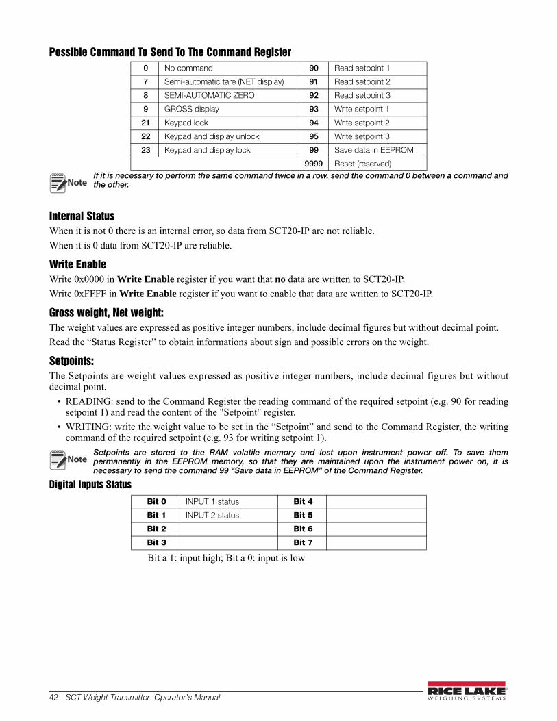
42 SCT Weight Transmitter Operator’s Manual
Possible Command To Send To The Command Register
If it is necessary to perform the same command twice in a row, send the command 0 between a command andthe other.
Internal StatusWhen it is not 0 there is an internal error, so data from SCT20-IP are not reliable.
When it is 0 data from SCT20-IP are reliable.
Write EnableWrite 0x0000 in Write Enable register if you want that no data are written to SCT20-IP.
Write 0xFFFF in Write Enable register if you want to enable that data are written to SCT20-IP.
Gross weight, Net weight:The weight values are expressed as positive integer numbers, include decimal figures but without decimal point.
Read the “Status Register” to obtain informations about sign and possible errors on the weight.
Setpoints:The Setpoints are weight values expressed as positive integer numbers, include decimal figures but withoutdecimal point.
• READING: send to the Command Register the reading command of the required setpoint (e.g. 90 for readingsetpoint 1) and read the content of the "Setpoint" register.
• WRITING: write the weight value to be set in the “Setpoint” and send to the Command Register, the writingcommand of the required setpoint (e.g. 93 for writing setpoint 1).
Setpoints are stored to the RAM volatile memory and lost upon instrument power off. To save thempermanently in the EEPROM memory, so that they are maintained upon the instrument power on, it isnecessary to send the command 99 “Save data in EEPROM” of the Command Register.
Digital Inputs Status
Bit a 1: input high; Bit a 0: input is low
0 No command 90 Read setpoint 1
7 Semi-automatic tare (NET display) 91 Read setpoint 2
8 SEMI-AUTOMATIC ZERO 92 Read setpoint 3
9 GROSS display 93 Write setpoint 1
21 Keypad lock 94 Write setpoint 2
22 Keypad and display unlock 95 Write setpoint 3
23 Keypad and display lock 99 Save data in EEPROM
9999 Reset (reserved)
Bit 0 INPUT 1 status Bit 4
Bit 1 INPUT 2 status Bit 5
Bit 2 Bit 6
Bit 3 Bit 7
Note
Note
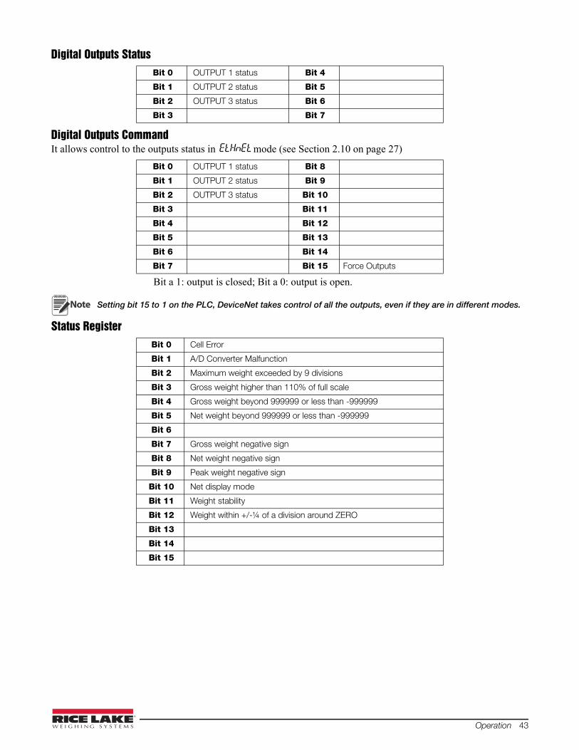
Operation 43
Digital Outputs Status
Digital Outputs CommandIt allows control to the outputs status in EtHnEt mode (see Section 2.10 on page 27)
Bit a 1: output is closed; Bit a 0: output is open.
Setting bit 15 to 1 on the PLC, DeviceNet takes control of all the outputs, even if they are in different modes.
Status Register
Bit 0 OUTPUT 1 status Bit 4
Bit 1 OUTPUT 2 status Bit 5
Bit 2 OUTPUT 3 status Bit 6
Bit 3 Bit 7
Bit 0 OUTPUT 1 status Bit 8
Bit 1 OUTPUT 2 status Bit 9
Bit 2 OUTPUT 3 status Bit 10
Bit 3 Bit 11
Bit 4 Bit 12
Bit 5 Bit 13
Bit 6 Bit 14
Bit 7 Bit 15 Force Outputs
Bit 0 Cell Error
Bit 1 A/D Converter Malfunction
Bit 2 Maximum weight exceeded by 9 divisions
Bit 3 Gross weight higher than 110% of full scale
Bit 4 Gross weight beyond 999999 or less than -999999
Bit 5 Net weight beyond 999999 or less than -999999
Bit 6
Bit 7 Gross weight negative sign
Bit 8 Net weight negative sign
Bit 9 Peak weight negative sign
Bit 10 Net display mode
Bit 11 Weight stability
Bit 12 Weight within +/-¼ of a division around ZERO
Bit 13
Bit 14
Bit 15
Note
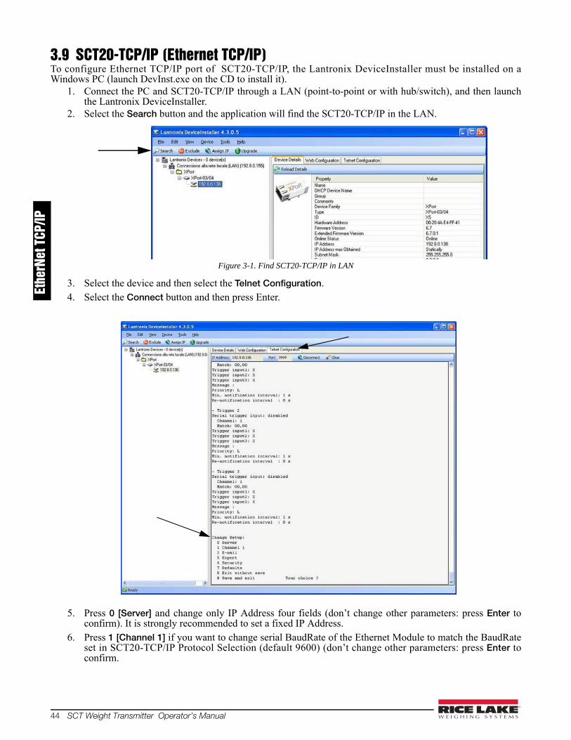
44 SCT Weight Transmitter Operator’s Manual
3.9 SCT20-TCP/IP (Ethernet TCP/IP)To configure Ethernet TCP/IP port of SCT20-TCP/IP, the Lantronix DeviceInstaller must be installed on aWindows PC (launch DevInst.exe on the CD to install it).
1. Connect the PC and SCT20-TCP/IP through a LAN (point-to-point or with hub/switch), and then launchthe Lantronix DeviceInstaller.
2. Select the Search button and the application will find the SCT20-TCP/IP in the LAN.
Figure 3-1. Find SCT20-TCP/IP in LAN
3. Select the device and then select the Telnet Configuration.4. Select the Connect button and then press Enter.
5. Press 0 [Server] and change only IP Address four fields (don’t change other parameters: press Enter toconfirm). It is strongly recommended to set a fixed IP Address.
6. Press 1 [Channel 1] if you want to change serial BaudRate of the Ethernet Module to match the BaudRateset in SCT20-TCP/IP Protocol Selection (default 9600) (don’t change other parameters: press Enter toconfirm.
Ethe
rNet
TCP
/IP
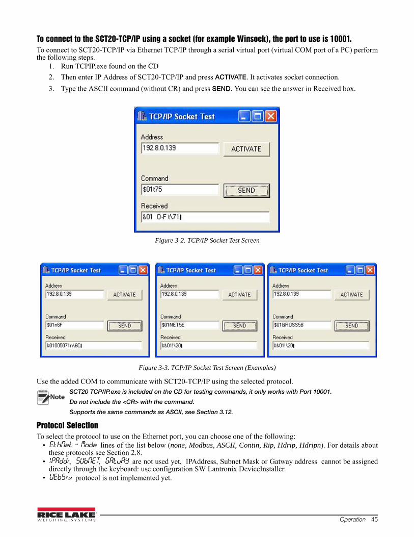
Operation 45
To connect to the SCT20-TCP/IP using a socket (for example Winsock), the port to use is 10001. To connect to SCT20-TCP/IP via Ethernet TCP/IP through a serial virtual port (virtual COM port of a PC) performthe following steps.
1. Run TCPIP.exe found on the CD
2. Then enter IP Address of SCT20-TCP/IP and press ACTIVATE. It activates socket connection.
3. Type the ASCII command (without CR) and press SEND. You can see the answer in Received box.
Figure 3-2. TCP/IP Socket Test Screen
Figure 3-3. TCP/IP Socket Test Screen (Examples)
Use the added COM to communicate with SCT20-TCP/IP using the selected protocol.SCT20 TCP/IP.exe is included on the CD for testing commands, it only works with Port 10001.
Do not include the <CR> with the command.
Supports the same commands as ASCII, see Section 3.12.
Protocol SelectionTo select the protocol to use on the Ethernet port, you can choose one of the following:
• EthNet - Modelines of the list below (none, Modbus, ASCII, Contin, Rip, Hdrip, Hdripn). For details aboutthese protocols see Section 2.8.
• IPAddr,SUbNET,GAtuAYare not used yet, IPAddress, Subnet Mask or Gatway address cannot be assigneddirectly through the keyboard: use configuration SW Lantronix DeviceInstaller.
• UEbSrvprotocol is not implemented yet.
Note

46 SCT Weight Transmitter Operator’s Manual
3.10 Modbus/TCPThe instrument works as a slave in a Modbus/TCP network. TLBMODBUSTCP instrument is configured withDHCP (default). IP Address can be automatically assigned by DHCP or manually via Telnet. To manually set theIP address via PC, type "telnet <ipaddress> 9999" and press Enter to confirm. The following screen appears:
1. Type “1” if you want to manually configure IP Address, Default Gateway Address and Netmask.
2. Then type “S” to save.
Modbus/TCP commands and registers of TLBMODBUS/TCP are the same as ModbusRTU protocol (see Section 3.11).
3.11 Modbus-RTU ProtocolThe MODBUS-RTU protocol enables management of the reading and writing of the registers listed here belowaccording to the specifications contained in the reference document for this standard Modicon PI-MBUS-300.
To select the communication with MODBUS-RTU, refer to Section 2.9 on page 24.
When specifically indicated certain data will be written directly to EEPROM type memories. This memory has alimited number of writing operations (100.000), therefore unnecessary operations at said locations must beavoided. The instrument, in any case, ensures that no writing occurs if the value to be stored is equal to the storedvalue.
The numerical data listed below are expressed in decimal notation, or hexadecimal notation if preceded by 0x.
Modbus-RTU Data FormatThe data received and transmitted via MODBUS-RTU protocol have the following characteristics:
- 1 start bit- 8 data bits, least significant bit sent first- Instrument settable parity bit- Instrument settable stop bit

Operation 47
Modbus Supported FunctionsAmong the commands available in the MODBUS-RTU protocol, only the following are used to managecommunication with the instruments. Other commands may not be interpreted correctly and could generate errorsor system shut-downs:
The interrogation frequency is linked with the preset communication rate (the instrument will stand by for at least 3bytes before beginning to calculate a possible response to the query). The dELAY parameter (see Section 2.9 onpage 24) allows for a further delay in the instrument response, and this directly influences the number of possiblequeries in the unit of time.
For additional information on this protocol, refer to the general technical specification PI_MBUS_300. In general,the query and response to and from a slave instrument are organized as follows:
Function 3: Read Holding Registers (Programmable Register Reading)
Tot. bytes = 8
Tot. bytes = 3+2*No. registers+2
in which:
No. registers= number of Modbus register to be read, starting from the Address 1° register;
No. bytes = number of data bytes to follow;
Function 16: Preset Multiple Registers (Multiple Register Writing)
Tot. bytes = 7+2*No. registers+2
Tot. bytes = 8
in which:
No. registers= number of Modbus register to be read, starting from the Address 1° register;
No. bytes = number of data bytes to follow;
Val. reg. 1 = register contents beginning from the first.
The response contains the number of records changed starting from the Address 1° register.
FUNCTIONS DESCRIPTION
03 (0x03) Read Holding Register (Programmable Register Reading)
16 (0x10) Preset Multiple Registers (Multiple Register Writing)
QUERY
Address Function Add. Reg. 1 No. register 2 bytes
A 0x03 0x0000 0x0002 CRC
RESPONSE
Address Function No. bytes Register1 Register 2 2 bytes
A 0x03 0x04 0x0064 0x00C8 CRC
QUERY
Address Function Add. reg. 1 No. reg. No. bytes Val. reg.1 Val. reg.2 2 bytes
A 0x10 0x0000 0x0002 0x04 0x0000 0x0000 CRC
RESPONSE
Address Function Add. Reg. 1 No. register 2 bytes
A 0x10 0x0000 0x0002 CRC

48 SCT Weight Transmitter Operator’s Manual
Communication Error ManagementThe communication strings are controlled by CRC (Cyclical Redundancy Check).
In case of a communication error the slave will not respond with any string. The master must allow for a time-outbefore response reception. If no response is received it infers that a communication error has occurred.
In the event of a string received correctly but not executable, the slave responds with an EXCEPTIONALRESPONSE. The "FUNCTION" field is transmitted with the msb at 1.
List Of Usable RegistersThe MODBUS-RTU protocol implemented on this instrument can manage a maximum of 32 registers read andwritten in a single query or response.
R = the register can be read onlyW = the register can be written onlyR/W = the register can be both read and writtenH = high half of the DOUBLE WORD forming the numberL = low half of the DOUBLE WORD forming the number
EXCEPTIONAL RESPONSE
Address Function Code 2 bytes
A Funct + 0x80 CRC
CODE DESCRIPTION
1 ILLEGAL FUNCTION (Function not valid or not supported)
2 ILLEGAL DATA ADDRESS (The specified data address is not available)
3 ILLEGAL DATA VALUE (The data received have no valid value)
REGISTER DESCRIPTION Saving to EEPROM ACCESS
40001 Firmware version - R
40002 Type of instrument - R
40003 Year of Production - R
40004 Serial Number - R
40005 Active program - R
40006 COMMAND REGISTER NO W
40007 STATUS REGISTER - R
40008 GROSS WEIGHT H - R
40009 GROSS WEIGHT L - R
40010 NET WEIGHT H - R
40011 NET WEIGHT L - R
40012 PEAK WEIGHT H - R
40013 PEAK WEIGHT L - R
40014 Divisions and Units of measure - R
40015 Coefficient H R
40016 Coefficient L R
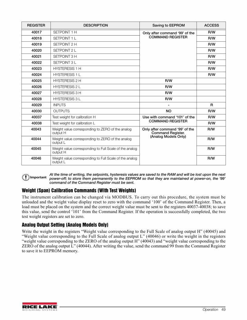
Operation 49
At the time of writing, the setpoints, hysteresis values are saved to the RAM and will be lost upon the nextpower-off; to store them permanently to the EEPROM so that they are maintained at power-on, the ‘99’command of the Command Register must be sent.
Weight (Span) Calibration Commands (With Test Weights)The instrument calibration can be changed via MODBUS. To carry out this procedure, the system must beunloaded and the weight value display reset to zero with the command ‘100’ of the Command Register. Then, aload must be placed on the system and the correct weight value must be sent to the registers 40037-40038; to savethis value, send the control ‘101’ from the Command Register. If the operation is successfully completed, the twotest weight registers are set to zero.
Analog Output Setting (Analog Models Only)Write the weight in the registers “Weight value corresponding to the Full Scale of analog output H” (40045) and“Weight value corresponding to the Full Scale of analog output L” (40046) or write the weight in the registers“weight value corresponding to the ZERO of the analog output H” (40043) and “weight value corresponding to theZERO of the analog output L” (40044). After writing the value, send the command 99 from the Command Registerto save it to EEPROM memory.
40017 SETPOINT 1 H Only after command ‘99’ of the COMMAND REGISTER
R/W
40018 SETPOINT 1 L R/W
40019 SETPOINT 2 H R/W
40020 SETPOINT 2 L R/W
40021 SETPOINT 3 H R/W
40022 SETPOINT 3 L R/W
40023 HYSTERESIS 1 H R/W
40024 HYSTERESIS 1 L R/W
40025 HYSTERESIS 2 H R/W
40026 HYSTERESIS 2 L R/W
40027 HYSTERESIS 3 H R/W
40028 HYSTERESIS 3 L R/W
40029 INPUTS - R
40030 OUTPUTS NO R/W
40037 Test weight for calibration H Use with command ‘101’ of the COMMAND REGISTER
R/W
40038 Test weight for calibration L R/W
40043 Weight value corresponding to ZERO of the analog output H
Only after command ‘99’ of the Command Register.
(Analog Models Only)
R/W
40044 Weight value corresponding to ZERO of the analog output L
R/W
40045 Weight value corresponding to Full Scale of the analog output H
R/W
40046 Weight value corresponding to Full Scale of the analog output L
R/W
REGISTER DESCRIPTION Saving to EEPROM ACCESS
Important
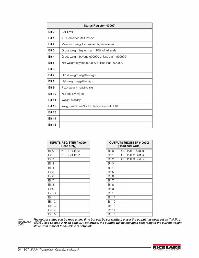
50 SCT Weight Transmitter Operator’s Manual
The output status can be read at any time but can be set (written) only if the output has been set as NOdbUS ordEUnEt (see Section 2.10 on page 27); otherwise, the outputs will be managed according to the current weightstatus with respect to the relevant setpoints.
Status Register (40007)
Bit 0 Cell Error
Bit 1 AD Convertor Malfunction
Bit 2 Maximum weight exceeded by 9 divisions
Bit 3 Gross weight higher than 110% of full scale
Bit 4 Gross weight beyond 999999 or less than -999999
Bit 5 Net weight beyond 999999 or less than -999999
Bit 6
Bit 7 Gross weight negative sign
Bit 8 Net weight negative sign
Bit 9 Peak weight negative sign
Bit 10 Net display mode
Bit 11 Weight stability
Bit 12 Weight within +/-¼ of a division around ZERO
Bit 13
Bit 14
Bit 15
INPUTS REGISTER (40029)(Read Only)
OUTPUTS REGISTER (40030)(Read and Write)
Bit 0 INPUT 1 Status Bit 0 OUTPUT 1 Status Bit 1 INPUT 2 Status Bit 1 OUTPUT 2 Status Bit 2 Bit 2 OUTPUT 3 Status Bit 3 Bit 3 Bit 4 Bit 4 Bit 5 Bit 5 Bit 6 Bit 6 Bit 7 Bit 7 Bit 8 Bit 8 Bit 9 Bit 9 Bit 10 Bit 10 Bit 11 Bit 11 Bit 12 Bit 12 Bit 13 Bit 13 Bit 14 Bit 14 Bit 15 Bit 15
Note
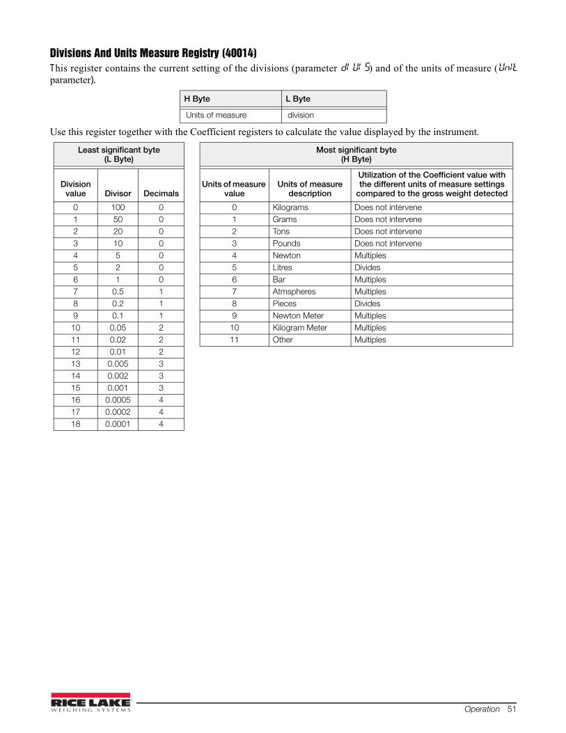
Operation 51
Divisions And Units Measure Registry (40014)This register contains the current setting of the divisions (parameter dI UI S) and of the units of measure (UnItparameter).
Use this register together with the Coefficient registers to calculate the value displayed by the instrument.
H Byte L Byte
Units of measure division
Least significant byte(L Byte)
Most significant byte(H Byte)
Division value Divisor Decimals
Units of measure value
Units of measure description
Utilization of the Coefficient value with the different units of measure settings
compared to the gross weight detected
0 100 0 0 Kilograms Does not intervene 1 50 0 1 Grams Does not intervene 2 20 0 2 Tons Does not intervene 3 10 0 3 Pounds Does not intervene 4 5 0 4 Newton Multiples 5 2 0 5 Litres Divides 6 1 0 6 Bar Multiples 7 0.5 1 7 Atmspheres Multiples 8 0.2 1 8 Pieces Divides 9 0.1 1 9 Newton Meter Multiples 10 0.05 2 10 Kilogram Meter Multiples 11 0.02 2 11 Other Multiples 12 0.01 2 13 0.005 3 14 0.002 3 15 0.001 3 16 0.0005 4 17 0.0002 4 18 0.0001 4

52 SCT Weight Transmitter Operator’s Manual
Possible Commands To Send To The Command Register (40006)
3.12 ASCII Bidirectional ProtocolAll the sample commands use address 1. If a different address is used it will need a different Check-Sumcalculated.
The instrument replies to the requests sent from a PC/PLC.
It is possible to set a delay time for the instrument before it transmits a response (see dELAY parameter in Section2.9 on page 24).
The following communication modes available (see Section 2.9 on page 24):
• NOdU60:
• NOd td:
Data Identifiers$: Beginning of a request string (36 ASCII);
& o &&: Beginning of a response string (38 ASCII);
aa: 2 characters for instrument address (48 ÷ 57 ASCII);
!: 1 character to indicate the correct reception(33 ASCII);
?: 1 character to indicate a reception error (63 ASCII);
#: 1 character to indicate an error in the command execution (23 ASCII);
ckck: 2 ASCII characters for Check-Sum (for further information, see “Check-Sum Calculation” onpage 56);
CR: 1 character for string end (13 ASCII);
\: 1 character for separation (92 ASCII).
0 No command 17 Reserved
1 18 Reserved
2 19
3 20
4 21 Keypad lock
5 22 Keypad and display unlock
6 23 Keypad and display lock
7 NET display 24
8 SEMI-AUTOMATIC ZERO 99 Save data in EEPROM
9 GROSS display 100 Zero-setting for calibration
10 Reserved 101 Test weight storage for calibration
11 Reserved
12 Reserved
13 Reserved
14 Reserved
15 Reserved
16 Reserved 9999 Reset (reserved)
Note

Operation 53
Setpoint Values Setting:The PC transmits : $aaxxxxxxyckckCR
in which:
xxxxxx = 6 characters for the setpoint value (48 ? 57 ASCII);
y = A (set the value in the Setpoint 1)$01010000A40CR
y = B (set the value in the Setpoint 2)$01010000B42CR
y = C (set the value in the Setpoint 3)$01010000C43CR
Possible instrument responses:
- correct reception: &&aa!\ckckCR
- incorrect reception: &&aa?\ckckCR
Setpoints Storage Into EEPROM Memory:The setpoints value relevant to the two setpoints programmed via the PC are stored to the RAM volatile memoryand lost upon instrument power off. It is necessary to send a special command to save them permanently in theEEPROM memory. Please note that the number of writes allowed in the EEPROM memory is limited (about100000).
The PC transmits: $aaMEMckckCR $01MEM44CR
Possible instrument responses:
- correct reception: &&aa!\ckckCR
- incorrect reception: &&aa?\ckckCR
Reading Weight, The Setpoint And The Peak (If Present) From The Pc:The PC transmits: $aajckckCR
in which:
j = a to read setpoint 1$01a60CR
j = b to read setpoint 2$01b63CR
j = c to read setpoint 3$01c62CR
j = t to read gross weight$01t75CR
j = n to read net weight$01n6FCR
j = p to read the gross weight peak if the ASCII parameter is set as NOdU60; if, instead the ASCII parameteris set on NOd td the gross weight will be read. To read the points, set the FS�tE0 equal to 50000. $01p71CR
Possible instrument responses:
- correct reception: &aaxxxxxxj\ckckCR
- incorrect reception: &&aa?\ckckCR
- if the peak is not configured: &aa#CR
in which:
xxxxxx = 6 value characters of the required weight;
In case of negative weight, the first character on the left acquires the value « - » (minus sign - ASCII 45).
In case of weight value is under -99999, the minus sign (‘-‘) is sent alternated with the most significant figure.
Error messages:
In case of an instrument alarm for exceeding 110% of the full scale or 9 divisions above the value of the parameterNASS, the instrument sends the string:
&aassO-Lst\ckck
In case of faulty connection of the load cells or of another alarm, the instrument sends:
&aassO-Fst\ckck
Note

54 SCT Weight Transmitter Operator’s Manual
in which:
s = 1 separator character (32 ASCII – space-).
Generally refer Section 3.5 “Alarms” on page 34.
Semi-Automatic Zero (Weight Zero-Setting For Small Variations)
The zero-setting will not be maintained after an instrument power-off.
The PC transmits: $aaZEROckckCR $01ZERO03CR
Possible instrument responses:
- correct reception: &&aa!\ckckCR
- incorrect reception: &&aa?\ckckCR
- the current weight is over the maximum value resettable: &aa#CR
Switching From Gross Weight To Net WeightThe PC transmits: $aaNETckckCR $01NET5ECR
Possible instrument responses:
- correct reception: &&aa!\ckckCR
- incorrect reception: &&aa?\ckckCR
Switching From Net Weight To Gross WeightThe PC transmits: $aaGROSSckckCR $01GROSS5BCR
Possible instrument responses:
- correct reception: &&aa!\ckckCR
- incorrect reception: &&aa?\ckckCR
Reading Of Decimals And Number Of DivisionsThe PC transmits: $aaDckckCR $01D45CR
Possible instrument responses:
- correct reception: &aaxy\ckckCR
- incorrect reception: &&aa?\ckckCR
in which:
x = number of decimals
y = division value
The y field acquires the following values:
'3' for division value = 1;
'4' for division value = 2;
'5' for division value = 5;
'6' for division value = 10;
'7' for division value = 20;
'8' for division value = 50;
'9' for division value = 100;
Important

Operation 55
Tare Weight Zero SettingThe PC transmit the following ASCII string containing the zeroing command: $aazckckCR $01z7BCR
in which:
z = weight zeroing command (122 ASCII)
Possible instrument responses:
- correct reception: &aaxxxxxxt\ckckCR
- incorrect reception: &&aa?\ckckCR
- If the instrument is not in gross weight displaying condition, the response is: &aa#CR
in which:
xxxxxx = 6 characters for the required weight value;
t = weight identification code (116 ASCII).
Example: Weight zero setting for instrument with address 2:
For the calibration, make sure that the scale is empty and the instrument measures a corresponding mV signal.
query: $02z78(Cr) response: &02000000t\76(Cr)
In case of correct weight zero setting the read value (response) must be 0 (in the string “000000”).
The zero values are stored to the EEPROM memory, please note that the number of writes allowed islimited (about 100000). If it is necessary to reset the weight quite often, it is recommended to perform itby PC or PLC program, keeping in mind the weight deviation respect to the zero instrument.
Weight (Span) Calibration (With Test Weights)After having performed the TARE WEIGHT ZERO SETTING, this function allows correct calibration to be doneusing test weights of known value and, if necessary, any deviations of the indicated value from the correct value tobe corrected.
Load the test weight onto the scale, use as high a percentage of the maximum quantity to be weighed as possible.Otherwise make sure that the instrument measures a corresponding mV signal.
The PC sends the following ASCII string containing the calibration command:
$aasxxxxxxckckCR
in which:
s = calibration command (115 ASCII)
xxxxxx = 6 characters for test weight value.
Possible instrument responses:
- correct reception: &aaxxxxxxt\ckckCR
- incorrect reception or full scale equal to zero: &&aa?\ckckCR
in which:
t = gross weight identification code (116 ASCII).
xxxxxx = 6 characters to indicate the current weight value.
In case of correct calibration, the read value must be equal to test weight.
Example: Calibration for instrument with address 1 and test weight of 20000 kg:
query: $01s02000070(Cr) response: &01020000t\77(Cr)
In case of correct calibration the read value has to be “020000”.
Important

56 SCT Weight Transmitter Operator’s Manual
Keypad Lock (Access Protection To The Instrument)The PC transmits: $aaKEYckckCR $01KEY56CR
Possible instrument responses:
- correct reception: &&aa!\ckckCR
- incorrect reception: &&aa?\ckckCR
Keypad UnlockThe PC transmits: $aaFREckckCR $01FRE50CR
Possible instrument responses:
- correct reception: &&aa!\ckckCR
- incorrect reception: &&aa?\ckckCR
Display And Keypad LockThe PC transmits: $aaKDISckckCR $01KDIS14CR
Possible instrument responses:
- correct reception: &&aa!\ckckCR
- incorrect reception: &&aa?\ckckCR
Check-Sum CalculationThe two ASCII control characters (ckck) are the representation of a hexadecimal digit in ASCII characters. Thecheck digit is calculated by performing the operation XOR (exclusive or) 8-bit ASCII codes of the only part of theunderlined string.
The procedure to calculate the check- sum is the following:
• Consider only the string characters highlighted with underlining;
• Calculate the EXCLUSIVE OR (XOR) of the ASCII codes for the characters;
Example:
• The result of the XOR operation expressed in hexadecimal notation is made up of 2 hexadecimal digits(numbers from 0 to 9 or letters from A to F). In this case the hexadecimal code is 0x75.
• The check-sum inserted in the strings transmitted is made up of the 2 characters which represent the result ofthe XOR operation in hexadecimal notation (in our example the character " 7 " and the character " 5)
Character Decimal ASCII Code Hexadecimal ASCII Code Binary ASCII Code
0 48 30 00110000
1 49 31 00110001
t 116 74 01110100
XOR = 117 75 01110101
Operation 57
3.13 Fast Continuous Transmission ProtocolThis protocol allows for continuous serial output at high update frequencies. Up to 300 strings per second aretransmitted (with a minimum transmission rate of 38400 baud). See Section 2.9 on page 24 for limitations.
Following communication modes available (see Section 2.9 on page 24):
• NOd t: communication compatible with TX RS485 instruments;
• NOd td: communication compatible with TD RS485 instruments.
• If NOd t is set, the following string is transmitted to PC/PLC: xxxxxxCRLF
in which:
xxxxxx = 6 ASCII characters for gross weight (48 ÷ 57 ASCII).
CR = 1 character of carriage return (13 ASCII).
LF = 1 character of line feed (10 ASCII).
In case of negative weight, the first character on the left acquires the value « - » (minus sign - ASCII 45).
In case of error or alarm, the 6 weight characters are replaced by the messages found in Table 3-1 onpage 34.
• If NOd td is set, the following string is transmitted to PC/PLC: &TzzzzzzPzzzzzz\ckckCR
in which:
& = 1 character of string start (38 ASCII).
T = reference character for gross weight.
P = reference character for gross weight.
zzzzzz = 6 ASCII characters for gross weight (48 ? 57 ASCII).
\ = 1 character of separation (92 ASCII).
ckck = 2 ASCII control characters calculated considering that the characters between & and \ are excluded. Thecontrol value is obtained by carrying out the XOR (or exclusive) operation for the 8 bit ASCII codes of thecharacters considered. A character expressed in hexadecimal is thus obtained, with 2 digits which may acquirevalues from “0” to “9” and from “A” to “F”. “ckck” is the ASCII code of the two hexadecimal digits.
CR = 1 character for string end (13 ASCII).
In case of negative weight, the first character on the left acquires the value « - » (minus sign - ASCII 45).
In case of error or alarm, the 6 gross weight characters are replaced by the messages found in the table of theALARMS.
Fast Transmission Via External Contact: A single string can be transmitted by closing a digital input, notexceeding 1 sec. (see Section 2.10 on page 27 and Section 2.9 on page 24).
3.14 Continuous Transmission ProtocolUsing this protocol, the instrument transmits, in continuous mode, the weight to remote displays; thecommunication string is transmitted 10 times per second. Following communication modes are available (seeSection 2.9 on page 24):
• rL P: remote display shows the net or gross weight, depending on the remote display setting.
• HdrL P: remote display shows the net or gross weight, depending on the remote display setting.
• HdrL Pn:
See following page for more information.
The instrument sends the following string to the remote display:
&NxxxxxxLyyyyyy\ckckCR
in which:
& = 1 character of string start (38 ASCII).
N = 1 reference character for net weight. (78 ASCII).
Note
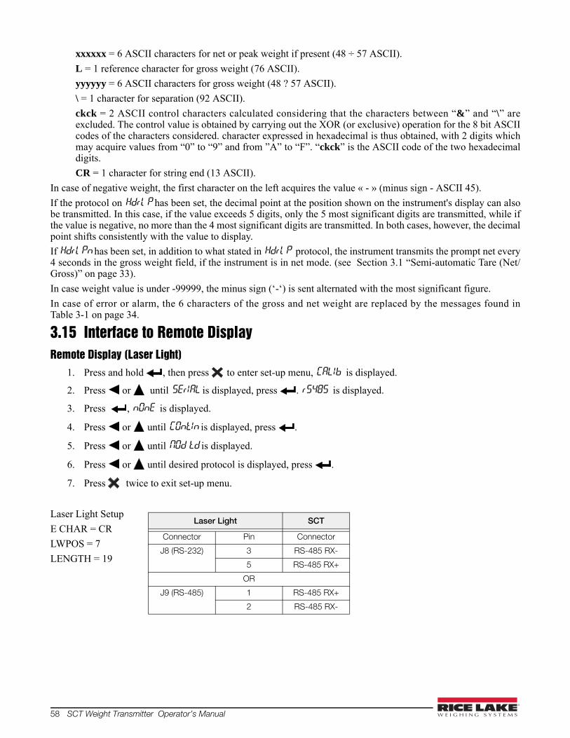
58 SCT Weight Transmitter Operator’s Manual
xxxxxx = 6 ASCII characters for net or peak weight if present (48 ÷ 57 ASCII).
L = 1 reference character for gross weight (76 ASCII).
yyyyyy = 6 ASCII characters for gross weight (48 ? 57 ASCII).
\ = 1 character for separation (92 ASCII).
ckck = 2 ASCII control characters calculated considering that the characters between “&” and “\” areexcluded. The control value is obtained by carrying out the XOR (or exclusive) operation for the 8 bit ASCIIcodes of the characters considered. character expressed in hexadecimal is thus obtained, with 2 digits whichmay acquire values from “0” to “9” and from ”A” to “F”. “ckck” is the ASCII code of the two hexadecimaldigits.
CR = 1 character for string end (13 ASCII).
In case of negative weight, the first character on the left acquires the value « - » (minus sign - ASCII 45).
If the protocol on Hdrl P has been set, the decimal point at the position shown on the instrument's display can alsobe transmitted. In this case, if the value exceeds 5 digits, only the 5 most significant digits are transmitted, while ifthe value is negative, no more than the 4 most significant digits are transmitted. In both cases, however, the decimalpoint shifts consistently with the value to display.
If Hdrl Pn has been set, in addition to what stated in Hdrl P protocol, the instrument transmits the prompt net every4 seconds in the gross weight field, if the instrument is in net mode. (see Section 3.1 “Semi-automatic Tare (Net/Gross)” on page 33).
In case weight value is under -99999, the minus sign (‘-‘) is sent alternated with the most significant figure.
In case of error or alarm, the 6 characters of the gross and net weight are replaced by the messages found inTable 3-1 on page 34.
3.15 Interface to Remote DisplayRemote Display (Laser Light)
1. Press and hold , then press to enter set-up menu, CALIb is displayed.
2. Press or until SErIAL is displayed, press . rS485 is displayed.
3. Press , nOnE is displayed.
4. Press or until COntIn is displayed, press .
5. Press or until NOd td is displayed.
6. Press or until desired protocol is displayed, press .
7. Press twice to exit set-up menu.
Laser Light Setup
E CHAR = CR
LWPOS = 7
LENGTH = 19
Laser Light SCT
Connector Pin Connector
J8 (RS-232) 3 RS-485 RX-
5 RS-485 RX+
OR
J9 (RS-485) 1 RS-485 RX+
2 RS-485 RX-
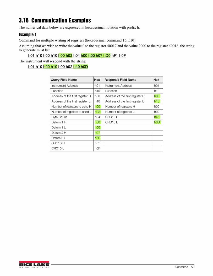
Operation 59
3.16 Communication ExamplesThe numerical data below are expressed in hexadecimal notation with prefix h.
Example 1Command for multiple writing of registers (hexadecimal command 16, h10):
Assuming that we wish to write the value 0 to the register 40017 and the value 2000 to the register 40018, the stringto generate must be:
h01 h10 h00 h10 h00 h02 h04 h00 h00 h07 hD0 hF1 h0FThe instrument will respond with the string:
h01 h10 h00 h10 h00 h02 h40 h0D
Query Field Name Hex Response Field Name Hex
Instrument Address h01 Instrument Address h01
Function h10 Function h10
Address of the first register H h00 Address of the first register H h00
Address of the first register L h10 Address of the first register L h10
Number of registers to send H h00 Number of registers H h00
Number of registers to send L h02 Number of registers L h02
Byte Count h04 CRC16 H h40
Datum 1 H h00 CRC16 L h0D
Datum 1 L h00
Datum 2 H h07
Datum 2 L hD0
CRC16 H hF1
CRC16 L h0F
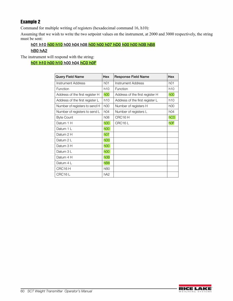
60 SCT Weight Transmitter Operator’s Manual
Example 2Command for multiple writing of registers (hexadecimal command 16, h10):
Assuming that we wish to write the two setpoint values on the instrument, at 2000 and 3000 respectively, the stringmust be sent:
h01 h10 h00 h10 h00 h04 h08 h00 h00 h07 hD0 h00 h00 h0B hB8hB0 hA2
The instrument will respond with the string:
h01 h10 h00 h10 h00 h04 hC0 h0F
Query Field Name Hex Response Field Name Hex
Instrument Address h01 Instrument Address h01
Function h10 Function h10
Address of the first register H h00 Address of the first register H h00
Address of the first register L h10 Address of the first register L h10
Number of registers to send H h00 Number of registers H h00
Number of registers to send L h04 Number of registers L h04
Byte Count h08 CRC16 H hC0
Datum 1 H h00 CRC16 L h0F
Datum 1 L h00
Datum 2 H h07
Datum 2 L hD0
Datum 3 H h00
Datum 3 L h00
Datum 4 H h0B
Datum 4 L hB8
CRC16 H hB0
CRC16 L hA2

Operation 61
Example 3Multiple command reading for registers (hexadecimal command 3, h03):
Assuming that we wish to read the two gross weight values (in the example 4000) and net weight values (in theexample 3000), reading from address 40008 to address 40011 must be performed by sending the following string:
H01 h03 h00 h07 h00 h04 hF5 hC8The instrument will respond with the string:
H01 h03 h08 h00 h00 hF hA0 h00 h00 h0B hB8 h12 h73
For additional examples regarding the generation of correct control characters (CRC16) refer to the manualModicon PI-MBUS-300.
Query Field Name Hex Response Field Name Hex
Instrument Address h01 Instrument Address h01
Function h03 Function h03
Address of the first register H h00 Address of the first register H h08
Address of the first register L h07 Address of the first register L h00
Number of registers to send H h00 Datum 1 H h00
Number of registers to send L h04 Datum 1 L h00
CRC16 H hF5 Datum 2 H h0F
CRC16 L hC8 Datum 2 L hA0
Datum 3 H h00
Datum 3 L h00
Datum 4 H h0B
Datum 4 L hB0
CRC16 H h12
CRC16 L h73

62 SCT Weight Transmitter Operator’s Manual
SCT Weight Transmitter Limited WarrantyRice Lake Weighing Systems (RLWS) warrants that all RLWS equipment and systems properly installed by aDistributor or Original Equipment Manufacturer (OEM) will operate per written specifications as confirmed by theDistributor/OEM and accepted by RLWS. All systems and components are warranted against defects in materialsand workmanship for one year. RLWS warrants that the equipment sold hereunder will conform to the current written specifications authorized byRLWS. RLWS warrants the equipment against faulty workmanship and defective materials. If any equipment failsto conform to these warranties, RLWS will, at its option, repair or replace such goods returned within the warrantyperiod subject to the following conditions:
• Upon discovery by Buyer of such nonconformity, RLWS will be given prompt written notice with adetailed explanation of the alleged deficiencies.
• Individual electronic components returned to RLWS for warranty purposes must be packaged to preventelectrostatic discharge (ESD) damage in shipment. Packaging requirements are listed in a publication,Protecting Your Components From Static Damage in Shipment, available from RLWS Equipment ReturnDepartment.
• Examination of such equipment by RLWS confirms that the nonconformity actually exists, and was notcaused by accident, misuse, neglect, alteration, improper installation, improper repair or improper testing;RLWS shall be the sole judge of all alleged non-conformities.
• Such equipment has not been modified, altered, or changed by any person other than RLWS or its dulyauthorized repair agents.
• RLWS will have a reasonable time to repair or replace the defective equipment. Buyer is responsible forshipping charges both ways.
• In no event will RLWS be responsible for travel time or on-location repairs, including assembly ordisassembly of equipment, nor will RLWS be liable for the cost of any repairs made by others.
These warranties exclude all other warranties, expressed or implied, including without limitation warranties ofmerchantability or fitness for a particular purpose. Neither RLWS nor distributor will, in any event, be liable forincidental or consequential damages. RLWS and buyer agree that RLWS’ sole and exclusive liability hereunder is limited to repair or replacement ofsuch goods. In accepting this warranty, the buyer waives any and all other claims to warranty.Should the seller be other than RLWS, the buyer agrees to look only to the seller for warranty claims.No terms, conditions, understanding, or agreements purporting to modify the terms of this warranty shall have anylegal effect unless made in writing and signed by a corporate officer of RLWS and the Buyer.
© Rice Lake Weighing Systems, Inc. Rice Lake, WI USA. All Rights Reserved.
RICE LAKE WEIGHING SYSTEMS • 230 WEST COLEMAN STREETRICE LAKE, WISCONSIN 54868 • USA

For More Information 63
For More Information
Web SiteFrequently Asked Questions (FAQs) at
• http://www.ricelake.com/faqs
Contact InformationHours of OperationKnowledgeable customer service representatives are available:
• 6:30 a.m. - 6:30 p.m. Monday through Friday
• 8 a.m. to 12 noon on Saturday. (CST)
Telephone• Sales/Technical Support 800-472-6703
• Canadian and Mexican Customers 800-321-6703
• International 715-234-9171
Immediate/Emergency ServiceFor immediate assistance call toll-free 1-800-472-6703 (Canadian and Mexican customers please call 1-800-321-6703). If you are calling after standard business hours and have an urgent scale outage or emergency, press 1 toreach on-call personnel.
FaxFax Number 715-234-6967
E-mailUS sales and product information at
International (non-US) sales and product information at • [email protected]
Mailing AddressRice Lake Weighing Systems230 West Coleman StreetRice Lake, WI 54868 USA

64 SCT Weight Transmitter Operator’s Manual


230 W. Coleman St. • Rice Lake, WI 54868 • USAU.S. 800-472-6703 • Canada/Mexico 800-321-6703 • International 715-234-9171 • Europe +31 (0) 88 2349171
www.ricelake.com www.ricelake.mx www.ricelake.eu www.ricelake.co.in m.ricelake.com© Rice Lake Weighing Systems March 12, 2014 PN 131128 Rev C