SCSSV Full Report
76
Tubing Retrievable Sub Surface Safety Valve Page 4 Project Report On “Tubing Retrievable Sub-Surface Safety Valves” Summer Internship 1 st June-25 th July2008 At Submitted To: Mr. Cecil Antao (Ops/Mktg Account Manager) Submitted By: Ashwin Soni Abhishek Bansal Metallurgical Engineering & Material Science Gas Engineering 2005-2010 2005-2009 IIT Bombay, Powai UPES, Dehradun
-
Upload
grand-pappy -
Category
Documents
-
view
1.079 -
download
100
description
Baker report for SCSSV
Transcript of SCSSV Full Report
Tubing Retrievable Sub Surface Safety Valve Page 4
Project Report
On
“Tubing Retrievable Sub-Surface
Safety Valves”
Summer Internship
1st June-25th July2008
At
Submitted To:
Mr. Cecil Antao
(Ops/Mktg Account Manager)
Submitted By:
Ashwin Soni Abhishek Bansal
Metallurgical Engineering & Material Science Gas Engineering
2005-2010 2005-2009
IIT Bombay, Powai UPES, Dehradun
Tubing Retrievable Sub Surface Safety Valve Page 5
ACKNOWLEDGEMENT
We sincerely thank Mr. C.K. Pathak (Country Manager, India & Bangladesh, BOT) for
providing us with this opportunity to learn and be part of this prestigious organization.
We would give our special thanks to Mr. Cecil Antao (Ops/Mktg Account Manager, BOT) for
guiding us throughout the eight week summer internship program and helping us in each
and every aspect as our mentor regardless of the busy schedule he had which kept our
morals high.
We give special thanks to Mr. Abhishek Kaushic (Sales Manager, BOT), Mr. Sushil Keshkar
(Ops/Mktg Account Manager, BOT), Mr. D.K. Shayamal (Ops/Mktg Account Manager, BOT)
and Mr. Rudappan Silvaguru (Field Service Manager, BOT) for providing us support and a
platform to interact with the BOT team.
We extend our sincere thanks to the Field Engineers, Commercial Team, Logistics and
Supply Chain Management Team, IT and Finance Department for providing us with the
knowledge of the operations and sharing their vast experiences with us.
This summer internship has been a valuable learning experience and has helped us gain a
perspective of the MNC culture and the corporate environment. We respect the core values
of the company “Integrity, Teamwork, Performance and Learning “and will try our best to
incorporate them into our actions. We thank Baker Oil Tools for providing us all the
information required and allowing us to use it in this report.
All in all being a part of Baker Hughes has been memorable and overwhelming.
Tubing Retrievable Sub Surface Safety Valve Page 6
CERTIFICATE
This is to certify that the project entitled
“Tubing Retrievable Sub-Surface Safety Valves”
Submitted by
Mr. Abhishek Bansal
B.Tech., Gas Engineering (2005-09)
from
University of Petroleum & Energy Studies, Dehradun
&
Mr. Ashwin Soni
Dual Degree, Metallurgical Engineering & Material Science (2005-10)
from
IIT Bombay, Powai
is an approved record of work carried out by them at
Baker Oil Tools, Baker Hughes, India Project Office, Mumbai
under proper guidance for a period of eight weeks
(w.e.f. 1st June to 25th July, 2008).
____________
Cecil Antao
(Ops/Mktg Account Manager)
Baker Oil Tools, Baker Hughes Asia Pacific Ltd.
Mumbai
Tubing Retrievable Sub Surface Safety Valve Page 7
1. A Brief Review of the Summer Internship
The summer internship at Baker Oil Tools started w.e.f. 1st June to 25th July i.e. for a period
of eight weeks. On the first day, the HSE orientation took place wherein we were told about
the Safety Policies of BOT. It was followed by a presentation on the core values of Baker
Hughes “Learning, Performance, Teamwork and Integrity”. In the following two weeks
presentations were delivered by the Finance Team, IT Team, Logistics and Supply Chain
Management Team and the Commercial Team. They envisioned us about the task their
team performs in order to carry out smooth and unrestricted operations in BOT.
For the next 6 weeks we were taken to workshops at ITS (International Tubular Services)
at Ghansoli and British Gas, Wadala situated in Mumbai. In the workshops we gained
valuable experience by working along with the Field Engineers. We learned about various
products of Baker Oil Tools such as Liner Hangers, Multilateral Assembly, Full Bore
Isolation Valve, External Casing Packer etc. We also assisted the Field Engineers working
on live project for the BOT customers like GSPC, BG and ONGC and participated in breaking
and redressing of various tools.
We also were taken to Baker INTEQ workshop for one day visit to have a glance of the
equipments available there.
On the last day of the Internship we delivered a presentation on the project to the BOT
team on the Project assigned to us i.e. “Tubing Retrievable Sub Surface Safety Valves”.
Tubing Retrievable Sub Surface Safety Valve Page 8
2. CONTENTS
ACKNOWLEDGEMENT ........................................................................................................................................ 5
1. A Brief Review of the Summer Internship ......................................................................................... 7
2. CONTENTS ..................................................................................................................................................... 8
3. LIST OF FIGURES AND TABLES .......................................................................................................... 12
4. INTRODUCTION ........................................................................................................................................ 13
5. BAKER HUGHES INCORPORATED ..................................................................................................... 14
5.1 About Baker Hughes ........................................................................................................................ 14
1.1.1 Drilling & Evaluation .................................................................................................................... 14
1.1.2 Completion & Production ........................................................................................................... 16
1.1.3 Reservoir Technology and Consulting................................................................................... 17
5.2 Financial Highlights ......................................................................................................................... 19
6. BAKER OIL TOOLS .................................................................................................................................... 20
6.1 THE Completion Company ............................................................................................................ 20
6.2 THE Workover Company ............................................................................................................... 20
6.3 THE Fishing Company .................................................................................................................... 20
7. SUB-SURFACE SAFETY SYSTEMS ....................................................................................................... 22
7.1 Introduction ........................................................................................................................................ 22
7.2 Overveiw .............................................................................................................................................. 23
Rating Envelope ........................................................................................................................................ 23
RBT Threads ............................................................................................................................................... 23
Unique Flapper Design ........................................................................................................................... 24
Chemical Injection Capabilities ........................................................................................................... 26

Tubing Retrievable Sub Surface Safety Valve Page 9
Control Line Connection ........................................................................................................................ 27
7.3 Basic Principle ................................................................................................................................... 29
1. Sub-Surface Controlled SSSV’s: ............................................................................................... 29
2. Surface Controlled SSSV’s: ........................................................................................................ 29
Contrast between SSCSV’s and SCSSV’s: .......................................................................................... 30
Versions of Safety Valves: ...................................................................................................................... 30
7.4 Industry Standards for Subsurface Safety Valves ................................................................ 31
8. Tubing Retrievable Surface Controlled Sub Surface Safety Valve (TRSCSSV) .................. 34
8.1 Assembly Drawing and Component List ................................................................................. 34
8.2 Working of a TRSCSSV .................................................................................................................... 36
8.3 Models Available ............................................................................................................................... 37
CEMENTSAFE™ SERIES SUBSURFACE SAFETY VALVE ........................................................... 38
Onyx™ SERIES SUBSURFACE SAFETY VALVES ............................................................................. 39
REALM™ SERIES SUBSURFACE SAFETY VALVE ........................................................................ 41
TITAN™ SERIES SUBSURFACE SAFETY VALVE ............................................................................ 42
SelecT™ SUBSURFACE SAFETY VALVE ............................................................................................ 44
NEPTUNE™ SERIES NITROGEN-CHARGED SUBSURFACE SAFETY VALVE ....................... 45
TRITON™ SERIES BALANCE LINESUBSURFACE SAFETY VALVE .......................................... 47
T-SERIES™ SUBSURFACE SAFETY VALVE ...................................................................................... 49
8.4 Models available in T-Series ......................................................................................................... 50
T (E) Series .................................................................................................................................................. 50
TM (E) Series .............................................................................................................................................. 50
TSM (E) Series and TUSM (E) Series ................................................................................................. 50
8.5 The Basic Hydrostatic Pressure Calculations ........................................................................ 51
8.6 Fail-Safe Setting Depth ................................................................................................................... 51
Tubing Retrievable Sub Surface Safety Valve Page 10
Fail-Safe Setting Depth Calculations ................................................................................................. 52
Opening and Closing Pressure Calculations ................................................................................... 53
8.7 Design Principles and Philosophy .............................................................................................. 56
Flow Tube Design Features .................................................................................................................. 56
Debris Exclusion/Control Design Consideration:- ...................................................................... 57
Scale Deposition prevention: ............................................................................................................... 57
Flow Tube Closure Assist Tool ............................................................................................................ 57
How side loading and torsional forces on a rod piston are perceived and designed for-
......................................................................................................................................................................... 58
Dual opposite wound Power Spring.................................................................................................. 59
8.8 Technical Evaluation of the ‘T’ Series SSV Equipment ....................................................... 59
Outer Housing thread seal design philosophy .............................................................................. 59
Permanent Lock Open Features.......................................................................................................... 60
Evaluation of dynamic seal assembly and metal-to-metal stop seals .................................. 60
Components of dynamic seal assemblies and metal-to-metal stop seals: .......................... 61
Baker Oil Tools' Detent System for the 'T'-Series Safety Valves ............................................ 63
Flapper and hinge pin design ............................................................................................................... 64
Table 3- Features and Benefits of Wedge Shape Flapper ......................................................... 65
Table 4- Features and Benefits of Curved (Slim line) Flapper ................................................ 66
Self-Equalizing Mechanism ................................................................................................................... 68
Control Line Jam Nut Connection ....................................................................................................... 72
Debris and Sand exclusion barriers .................................................................................................. 73
8.9 ‘T’ Series accessory tools ............................................................................................................... 74
Flapper Lock Open Tool ......................................................................................................................... 74
Wireline Insert Safety Valve ................................................................................................................. 75
Tubing Retrievable Sub Surface Safety Valve Page 11
Separation Sleeve ..................................................................................................................................... 76
Control Pressure Communication Tool............................................................................................ 77
9. CONCLUSION .............................................................................................................................................. 78
10. BIBLIOGRAPHY ...................................................................................................................................... 79

Tubing Retrievable Sub Surface Safety Valve Page 12
3. LIST OF FIGURES AND TABLES
Table 1- List of TE 5 (5.5") Components ................................................................................................... 35
Table 2- Fail Safe Setting Depth Calculations for the T (E) - 5 (5.5”) model (7) ........................ 55
Table 3- Features and Benefits of Wedge Shape Flapper ................................................................... 65
Table 4- Features and Benefits of Curved (Slim line) Flapper ......................................................... 66
Figure 1- RBT Thread Performance Envelope ........................................................................................ 24
Figure 2- Self Equalizing Mechanism ......................................................................................................... 25
Figure 3-Curved Flappers ............................................................................................................................... 26
Figure 4-Chemical injection feature simplifies the completion and maximizes the benefits
from injection process ............................................................................................................................ 27
Figure 5- Control line and its connections ............................................................................................... 28
Figure 6- A Sub Surface Safety Valve .......................................................................................................... 29
Figure 7- Model "T (E)-5" Safety Valve (Assembly Drawing) (7) .................................................... 34
Figure 8- Subsurface Safety Valve Type .................................................................................................... 37
Figure 9- RBT Thread connection................................................................................................................ 59
Figure 10- Dynamic Seal Assembly ............................................................................................................. 61
Figure 11- Location of Metal to Metal Stop Seal .................................................................................... 62
Figure 12- Detent System/Shock Absorber ............................................................................................. 63
Figure 13- Wedge Shaped Flapper (Three point contact shown above) ...................................... 64
Figure 14- Curved Flapper Design .............................................................................................................. 66
Figure 15- Single Hinge Flapper Assembly .............................................................................................. 67
Figure 16- Baker Jam Nut ............................................................................................................................... 72
Figure 17- Debris and Sand Exclusion Barriers ..................................................................................... 73
Figure 18- Flapper Lock Open Tool ............................................................................................................ 74
Figure 19- Wireline Insert Safety Valve .................................................................................................... 75
Figure 20- Control Pressure Communication Tool ............................................................................... 77
Tubing Retrievable Sub Surface Safety Valve Page 13
4. INTRODUCTION
The safety systems are required for the protection of the personnel around the platform,
the environment and to prevent any production losses. It is also required for shutting in a
well, in case of emergency shut down due to catastrophe, production testing, inspection
and other routine operations. The safety valves keep the well shut in when the control line
pressure is released and open up when the pressure is again maintained (in surface
controlled type safety valves). There are various versions of such subsurface safety valves
available with Baker Oil Tools. They are either surface controlled or subsurface controlled.
The surface controlled one is available in two types, one is tubing retrievable and other is
wireline retrievable. The tubing retrievable subsurface safety valves are most widely used
in the oil industry and are available in various models for various applications. They are
available in various designs offering different features which have been discussed further.
Tubing Retrievable Sub Surface Safety Valve Page 14
5. BAKER HUGHES INCORPORATED
5.1 About Baker Hughes
(1)Baker Hughes provides the worldwide oil and natural gas industry products and
services for drilling, formation evaluation, completion and production. We create value for
oil and gas producers by providing advanced, reliable technology to find, develop, produce
and manage oil and gas reservoirs. We also provide reservoir engineering and other
consulting services. Baker Hughes operates in over 90 countries serving independent,
international and national oil companies.
Baker Hughes is the only major oilfield service company structured around strong product-
line divisions that are focused on Best-in-Class products and services. Our divisions are
organized in two segments -- Drilling & Evaluation and Completion & Production -- which
share common opportunities in developing and delivering technology solutions during
distinct phases of oil and gas development.
The newly-formed Reservoir Technology and Consulting Group includes two consulting
firms – Gaffney, Cline & Associates and GeoMechanics International – that provide technical
and commercial consulting, with unique capabilities in reservoir engineering and
geomechanics.
1.1.1 Drilling & Evaluation
Our Drilling & Evaluation segment includes divisions that apply their products and services
primarily during the drilling process to improve efficiency, reduce risk and acquire
accurate information. The segment includes Baker Atlas, Baker Hughes Drilling Fluids,
INTEQ and Hughes Christensen.

Tubing Retrievable Sub Surface Safety Valve Page 15
Baker Atlas
Baker Atlas offers a complete range of down-hole well logging services for every
environment including advanced formation evaluation, production and reservoir
engineering, petro-physical and geophysical data acquisition services. In addition,
perforating and completion technologies, pipe recovery, and processing and analysis of
open and cased hole data complete the service range.
Baker Hughes Drilling Fluids
Baker Hughes Drilling Fluids provides fluids systems and services that help optimize the
drilling and completion processes maximize hydrocarbon production and manage drilling
waste. Leading technologies include environmentally compliant water-based and
synthetic-based mud systems and remediation fluids that can restore productivity from
damaged wells.
INTEQ
INTEQ provides real-time services to help oil companies drill more efficiently, evaluate
geologic formations, and place wells in productive zones within the reservoir. Important
technologies include automated rotary steerable directional drilling systems, high
performance drilling motors, and integrated logging-while-drilling assemblies. INTEQ also
provides data communications, data management and expert centers to improve drilling
operations and enhance formation evaluation.
Hughes Christensen
Hughes Christensen is the leader in Tricone™ and PDC drill bit, ream-while-drilling and
casing drilling technology. Hughes Christensen application and design engineers work with
customers to provide the best drill bit for the application to continuously improve drilling
performance.
Tubing Retrievable Sub Surface Safety Valve Page 16
1.1.2 Completion & Production
Our Completion & Production segment includes divisions that apply their products and
services primarily during the well completion, field production, transportation and refining
processes. The segment includes Baker Oil Tools, Baker Petrolite, Centrilift, and the
Production Optimization business unit.
Baker Oil Tools
Baker Oil Tools provides completion and intervention solutions that help manage cost and
reduce risk while optimizing production. The division has a comprehensive line of
completion systems, which maximize performance and safety from the reservoir to the
surface. Wellbore intervention solutions address issues ranging from temporary well
abandonment and fishing to casing exits, wellbore cleaning, and isolation, remediation and
stimulation operations.
Baker Petrolite
Baker Petrolite provides chemical technology solutions for hydrocarbon production,
transportation and processing, and also delivers pipeline integrity services. Baker Petrolite
is a leader in oil/water separation technology and in solutions to control corrosion,
deposition, bacteria and H2S in producing wells and production facilities. To serve refinery
and petrochemical customers, Baker Petrolite provides chemicals and technical support to
enhance plant processes, improve productivity, manage water treatment, and resolve
environmental issues.
Centrilift
Centrilift provides artificial lift systems, including electric submersible pumps (ESP) and
progressive cavity pump systems, as well as specific engineering, project management and
well monitoring services. Centrilift has expanded the applications for ESP systems to harsh
downhole environments that include high gas to oil ratio, heavy oil, high temperatures and
abrasive laden fluids. New systems also address the needs of coalbed methane and subsea
production.
Tubing Retrievable Sub Surface Safety Valve Page 17
ProductionQuest
Baker Hughes formed its ProductionQuest business unit to provide technology and services
that help maximize recovery from both new and mature fields. The unit provides
production optimization services centered on the well bore, including permanent
monitoring, chemical automation, intelligent production systems, and consulting services.
The unit also includes the Baker Hughes Integrated Operations group, which manages
projects and combines technologies and services from Baker Hughes divisions and
subcontractors to meet customer objectives for both well construction and production
optimization.
1.1.3 Reservoir Technology and Consulting
Baker Hughes recently formed the Reservoir Technology and Consulting Group to enhance
the company’s capabilities in reservoir engineering, geomechanics and energy consulting
services. The group currently includes Gaffney, Cline & Associates and Geomechanics
International, Inc., which continue to operate as stand-alone consulting firms.
Gaffney Cline & Associates
Gaffney Cline & Associates is an international advisory firm focused on providing
integrated technical and managerial services to all sectors of the oil and gas industry. For
more than 45 years GCA has provided strategic and detailed advice aimed at achieving
practical and commercially viable results. In addition to reservoir engineering, GCA advises
a wide group of clients in exploration, reservoir evaluation, field development, drilling and
production, pipeline, refining and LNG projects throughout the world.
GeoMechanics International
GeoMechanics International is a leader in consulting, training and software in the field of
geomechanics and its application to oil and gas reservoirs. GMI was founded in 1996 by a
team of experts from Stanford University's Department of Geophysics, and each of its
Tubing Retrievable Sub Surface Safety Valve Page 18
consultants is a recognized leader in the field of geomechanics. GMI methods are focused
on applying geomechanics modeling to the entire life of a reservoir and are based on 20
years of R&D and more than 12 years of practical application to oilfield problems. These
methods have been proven to reduce exploration risk, save Non-Productive Time (NPT)
and help increase production and recoverable reserves.
Tubing Retrievable Sub Surface Safety Valve Page 19
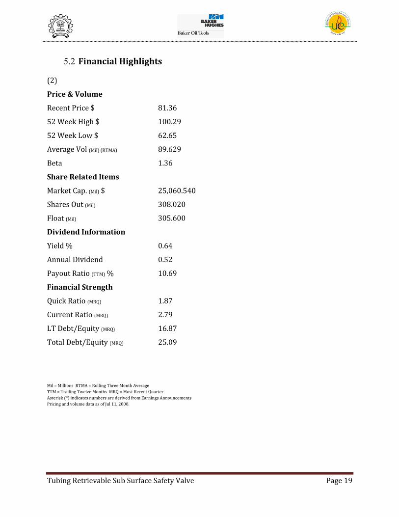
5.2 Financial Highlights
(2)
Price & Volume
Recent Price $ 81.36
52 Week High $ 100.29
52 Week Low $ 62.65
Average Vol (Mil) (RTMA) 89.629
Beta 1.36
Share Related Items
Market Cap. (Mil) $ 25,060.540
Shares Out (Mil) 308.020
Float (Mil) 305.600
Dividend Information
Yield % 0.64
Annual Dividend 0.52
Payout Ratio (TTM) % 10.69
Financial Strength
Quick Ratio (MRQ) 1.87
Current Ratio (MRQ) 2.79
LT Debt/Equity (MRQ) 16.87
Total Debt/Equity (MRQ) 25.09
Mil = Millions RTMA = Rolling Three Month Average
TTM = Trailing Twelve Months MRQ = Most Recent Quarter
Asterisk (*) indicates numbers are derived from Earnings Announcements
Pricing and volume data as of Jul 11, 2008.
Tubing Retrievable Sub Surface Safety Valve Page 20
6. BAKER OIL TOOLS
(3)Baker Oil Tools leads the world in completion, workover and fishing solutions that help
exploration and production companies maximize value from their hydrocarbon-bearing
assets. Since its earliest days, the Baker name has been synonymous with excellence in
down-hole and surface technology, performance and reliability. In the current era of riskier
environments and higher stakes, those qualities are more valuable than ever.
6.1 THE Completion Company
Baker Oil Tools′ undisputed role as the industry leader in reliable, performance-based
completion solutions is based on the world′s most reliable sealing and anchoring
technologies, meticulous planning, and a no-nonsense approach to risk avoidance. From
the Model D Packer to the FORMation Junction™ Multilateral Completion System, H2O-
PAQSM and H2O-FRAQSM production enhancement processes, and InForce™ and
InCharge™ Intelligent Well System and High-pressure/high-temperature environments –
Baker has built a track record second to none by working closely with its customers to
meet or exceed their needs in virtually every completion application.
6.2 THE Workover Company
When well maintenance or remediation operations become necessary, Baker Oil Tools
applies more than five decades of industry-leading mechanical and inflatable packer
technologies to provide integrated solutions that maximize productivity and minimize cost.
At the forefront of Baker′s capabilities are its award-winning through-tubing workover
technologies, which allow zonal isolations, water shutoffs and well cleanouts to be
performed simply, without killing the well or pulling the production tubing.
6.3 THE Fishing Company
Fast, reliable solutions and around-the-world/around-the-clock service make Baker Oil
Tools the preferred provider for both traditional and through-tubing fishing and re-entry
projects. Baker engineers apply practical field experience to industry-leading cutting,
Tubing Retrievable Sub Surface Safety Valve Page 21
fishing and milling capabilities to provide a range of solutions that are the most advanced
and comprehensive available.

Tubing Retrievable Sub Surface Safety Valve Page 22
7. SUB-SURFACE SAFETY SYSTEMS
7.1 Introduction
(4)In 1969, an operator lost control of a platform and spilled 4.2 million gallons of crude
into the ocean, killing birds and contaminating beaches. Over 10,000 Loons and Western
Grebes were killed. This spill was off the coast of Santa Barbara, encircled Anacapa and the
eastern each of Santa Cruz Island, and earned the distinction of being the largest oil spill in
California not to mention the most publicised. The Santa Barbara oil spill is considered one
of the key events responsible for promoting the modern environmental movement.
A post-mortem on the accident showed that the well developed a leak in the tubing and
casing between the ocean floor and ocean surface. This allowed the oil to flow, unchecked,
into the ocean. Several attempts to regain control proved to be unfruitful. The well was
finally brought under control by drilling a relief well and pumping in heavy fluids. This
highly visible spill brought public attention to the need of safety equipment. A Subsurface
Safety Valves would have allowed the operator to regain control of the oil flow
immediately.
Shortly after the Santa Barbara oil spill, the petroleum industry began an accelerated
program for the development of standards in relation to safety valves. The American
Petroleum Institute’s Production Department in Dallas, took the lead in developing
specifications and funding an independent test laboratory. Initial testing was done from
1973 - 1974 at Southwest Research Institute in San Antonio, Texas.
Tubing Retrievable Sub Surface Safety Valve Page 23
7.2 Overveiw
Baker Oil Tools (BOT) is one of the leading suppliers of subsurface safety system
equipment. Full line of subsurface safety valves are available for surface-controlled and
subsurface-controlled tubing retrievable and wireline retrievable applications. Each valve
includes Baker's proven technologies and innovations that have set many industry
standards.
Rating Envelope
The combination of innovative computer programs and exhaustive laboratory testing has
enabled Baker Oil Tools to develop an industry standard for predicting safety valve housing
performance capabilities under all loading conditions. This conservative design approach
ensures the thread's ability to withstand aggressive down-hole environments. The results
of this evaluation are plotted in a graphical format which provides visual indication of the
safe operating range for the safety valve. With this load envelope, operators can safely plan
their completions with confidence that Baker Oil Tools' safety valves will protect their
people and investments.
RBT Threads
Through extensive FEA analysis and technical research, Baker Oil Tools offers RBT
premium thread connections. The efficiency of the RBT thread design allows Baker Oil
Tools to offer the smallest OD's for a given tubing size across the safety valve portfolio. The
RBT premium thread connections bring the superior protection and life extending
advantages of metal-to-metal sealing technology to thousands of Baker safety valves. The
connection's two-step design distributes thread load to impart greater strength than
single-step designs. The metal-to-metal seal points at the box and pin noses provide
enhanced pressure-containing capabilities. The combination of this two-step, ultra slim-
profile thread and the use of high tensile strength materials allows for the slimmest outside
diameters on the market.

Tubing Retrievable Sub Surface Safety Valve Page 24
Figure 1- RBT Thread Performance Envelope
The RBT thread also includes an innovative center torque shoulder design. The torque
shoulder provides superior resistance to back-off in down-hole service. In addition,
damage is prevented to the metal-to-metal seals during high torque loads and precisely
controls make-up loss.
Unique Flapper Design
Focusing on providing customer solutions along with using state of the art engineering
practices, Baker Oil Tools has introduced several industry firsts relating to its unique
flapper design. Baker Oil Tools was the first to offer a patented through the flapper self-
equalizing feature which has proven to reduce operating costs for operators. The self-
equalizing feature allows operators to open subsurface safety valves against differential
pressure.

Tubing Retrievable Sub Surface Safety Valve Page 25
Figure 2- Self Equalizing Mechanism
This unique design is resilient to debris and erosion which provides ultimate long-term
reliability. The equalizing system has been used successfully in HP/HT and Big Bore
applications where equalizing high pressures and large volumes can prove challenging.
Baker Oil Tools also provided the industry's first wireline damage resistant flapper design.
This design was created after careful review of mean-time-to-failure statistics relating to all
subsurface safety valve designs. This analysis revealed that a good portion of failures could
be eliminated with a wireline damage resistant flapper. The new flapper design protects
the seal surface from wireline damage if an operator accidentally closes the valve during
wireline operations. The protection offered by the wireline damage resistant flapper
extends the safety valve life for operators.
Baker Oil Tools was the first company to design a 4-1/2 in. safety valve to be installed
inside 7 in. casing and a 7 in. safety valve to be installed inside 9-5/8 in. casing. The key
ingredient to this success was the unique curved flapper design. The curved flapper design
was made possible by advanced machining processes, innovative engineering practices,
and exceptional quality control. These ultra-slimline curved flappers allow operators to
reduce their overall costs and maximize their return on investment by maintaining a large
bore ID while reducing the casing sizes needed for the completion.
Tubing Retrievable Sub Surface Safety Valve Page 26
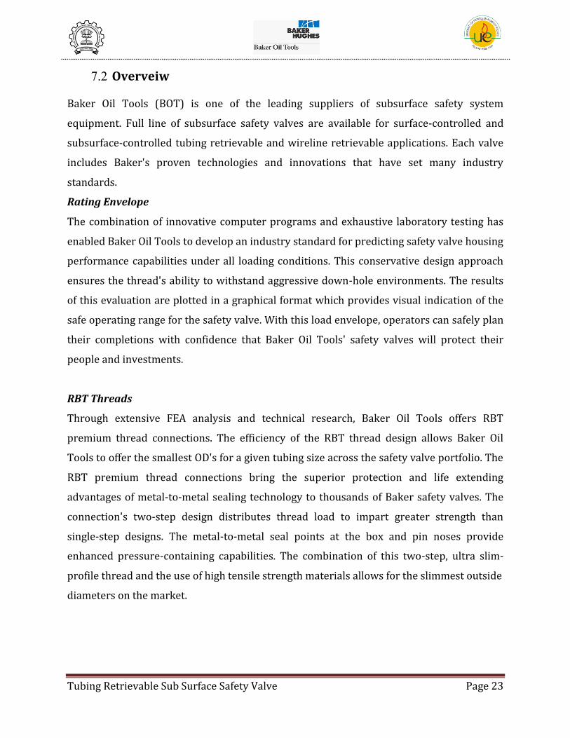
Figure 3-Curved Flappers
For high flow rate natural gas applications, Baker Oil Tools recognized the need to design
and manufacture one of the world's most rugged flapper designs. Every flapper design goes
through an intricate engineering process to ensure the flapper can meet the demands of
high gas velocities. Baker Oil Tools' flapper designs have been verified by gas slam tests to
the highest rates available in the world.
Chemical Injection Capabilities
Scale, paraffin, or hydrate formation continues to pose significant risks to operators in
obtaining desired returns on their investments. Formation of these solids can jeopardize
safety valve function by impeding flow tube movement, thereby requiring intervention.
With this in mind, it is the culture within Baker Oil Tools to look for ways to simplify
completion designs that will increase system reliability and decrease operator cost while
maximizing performance.
Tubing Retrievable Sub Surface Safety Valve Page 27
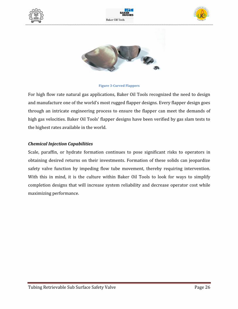
Figure 4-Chemical injection feature simplifies the completion and maximizes the benefits from injection process
A result of this culture is the optional chemical injection feature available with the Titan™
Series Subsurface Safety Valve. This innovative design incorporates a field-proven double-
poppet system that permits chemical injection directly into the safety valve. Combining this
feature with a Titan Valve will virtually eliminate the need for any chemical injection
mandrel in the tubing string above the safety valve. This will save the customer money and
simplify the completion by reducing the number of components and tubing connections.
Injecting chemicals directly into the spring cavity also ensures that the customer will
receive the maximum benefit of the injection process by allowing injection directly where it
is needed. For valve designs that do not offer the integral chemical injection feature, Baker
Oil Tools offers a chemical injection sub that can be mounted directly on top of the Tubing
Retrievable Safety Valve (TRSV).
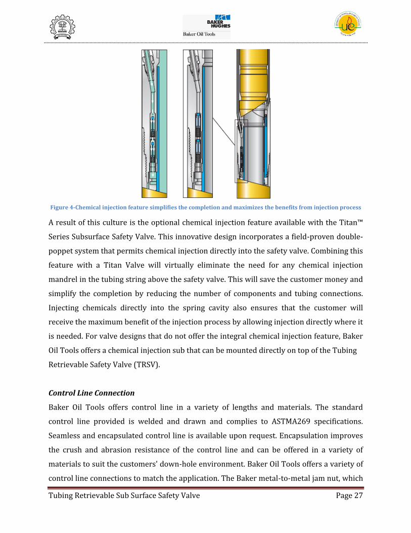
Control Line Connection
Baker Oil Tools offers control line in a variety of lengths and materials. The standard
control line provided is welded and drawn and complies to ASTMA269 specifications.
Seamless and encapsulated control line is available upon request. Encapsulation improves
the crush and abrasion resistance of the control line and can be offered in a variety of
materials to suit the customers' down-hole environment. Baker Oil Tools offers a variety of
control line connections to match the application. The Baker metal-to-metal jam nut, which
Tubing Retrievable Sub Surface Safety Valve Page 28
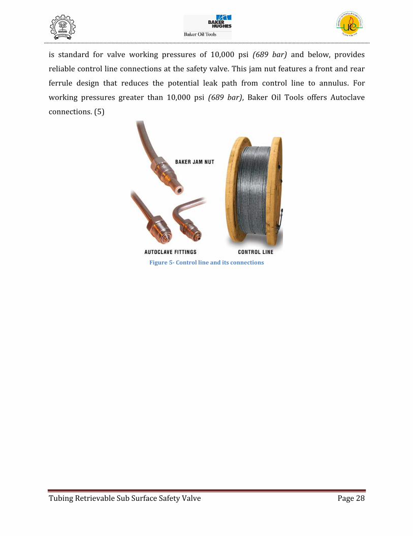
is standard for valve working pressures of 10,000 psi (689 bar) and below, provides
reliable control line connections at the safety valve. This jam nut features a front and rear
ferrule design that reduces the potential leak path from control line to annulus. For
working pressures greater than 10,000 psi (689 bar), Baker Oil Tools offers Autoclave
connections. (5)
Figure 5- Control line and its connections

Tubing Retrievable Sub Surface Safety Valve Page 29
7.3 Basic Principle
Depending on the environment and on the type and pressure of the produced effluent, it
may be necessary to place a SubSurface Safety Valve, SSSV, inside the well itself. It
supplements the one(s) on the wellhead if they should happen to be out of order (valve
failure, wellhead torn off, etc).
(6)There are two types of SSSV’s:
1. Sub-Surface Controlled SSSV’s:
These valves that were often called storm chokes are now termed SSCSV (SubSurface
Controlled Subsurface Safety Valves). They are set and retrieved by wireline. They close the
well following a modification in flow conditions where they are located:
a) Either when the ambient flow rate increases (and so the pressure loss across the
valve also increases)
b) When there is a pressure drop opposite the valve.
Baker Oil Tools Manufactures injection valves and velocity valves which fall under
SSCSV’s
2. Surface Controlled SSSV’s:
The SCSSV’s (Surface Controlled Subsurface Safety Valve), of the fail safe type, are
controlled from the surface by hydraulic pressure in the control line and are normally
closed (i.e. closed when no pressure is applied in the control line). The control pressure
acts n a jack which pushes a sleeve back thereby opening the valve. At the same time it
compresses a powerful return spring. As long as the control pressure is kept at the set
Figure 6- A Sub Surface Safety Valve

Tubing Retrievable Sub Surface Safety Valve Page 30
operating value, the valve remains open. However, if it falls below a certain threshold then
the valve will close automatically solely under the effect of the return spring.
Contrast between SSCSV’s and SCSSV’s:
The SCSSV does not depend directly on ambient flow conditions in the well, but rather on
one or more parameters measured at the well head. This also allows the subsurface valve
to be controlled via a number of safety systems connected to process facilities. The well’s
safety can therefore be achieved manually or automatically whether the trouble is directly
related to the well or not: fire, explosion or impact, process problem, etc. Depending on the
degree of safety required, the wellhead safety valve alone can be closed or, in conjunction
with it, the subsurface safety valve can also be closed.
Due to the design of the hydraulically controlled valve, the depth at which it can be
installed in the well is limited by the capacity of its running string. The spring must be
sufficiently compressed to overcome the opposing force due to the weight of the
hydrostatic column of the hydraulic fluid in the control line that governs the valve and acts
directly on the jack.
Also due to its design, the valve could not be opened as long as the pressure difference
between above and below the closing and sealing mechanism exceeds an average of 0.7
MPa (100 psi), so that the valve will not be damages when it opens. Some valves are
equipped with an internal equalization device. Here, all that is required to reopen the
valves is to increase the pressure in the control line with the well head closed. Otherwise it
is also necessary to recompress the tubing above the valve (by means of a pump, a nearby
well, etc.)
The SCSSV closing and sealing mechanism is either a flapper valve or a ball valve. For a long
time preference was given to ball valves, mainly because of the sealing quality, even though
the sleeve weldment (pivot cage) is complex and fragile. Currently check valves seem to be
preferred choice as they are much simpler, more rugged and robust (i.e. safer). Also, a lot of
progress has been made regarding the reliability and tightness of flappers.
Versions of Safety Valves:
1. Wireline Retrievable: Set in a special landing nipple and retrieved by wireline.

Tubing Retrievable Sub Surface Safety Valve Page 31
2. Tubing Retrievable: Screwed onto the tubing and pulled out with all or part of the
equipment in the well.
7.4 Industry Standards for Subsurface Safety Valves
The recognized industry standard for Subsurface Safety Valve systems is published in the
American Petroleum Institute Specifications, API Spec 14A and API RP 14B. These two
documents prescribe the minimum standards for quality assurance and performance to provide
the maximum reliability of Subsurface Safety Valve equipment. They also provide guidelines for
the design, installation and operations of safety valve systems. The following is a brief overview
of these standards.
API 14A
The API 14A specification covers Subsurface Safety Valves, Safety Valve Locks, Safety Valve
Landing Nipples, and all components that establish tolerance and/or clearances which may affect
performance or interchangeability.
Classes of Service
Subsurface safety valves, safety valve locks and safety valve landing nipples must meet
acceptable standards for materials manufacturing and testing for one of four classes of service.
Class 1 - Standard Service is for use in oil or gas wells which do not exhibit the
detrimental effects caused by sand or stress corrosion cracking.
Class 2 - Sandy Service is for use in oil or gas wells where a substance such as sand
could cause valve malfunction or failure (this valve must also meet the Class 1 service
requirements).
Class 3 - Stress Corrosion Cracking Service is for use in oil or gas wells where corrosive
agents could cause stress corrosion cracking. This valve must meet the requirements for a
Class 1 and Class 2 valve and be manufactured from materials which are resistant to
stress corrosion cracking.
Within this service class there are two sub-classes, 3S for sulfide stress cracking service and 3C
for chloride stress cracking service. Metallic material, suitable for a 3S environment, shall be in
accordance with NACE MR0175.
Tubing Retrievable Sub Surface Safety Valve Page 32
Class 4 - Weight Loss Corrosion Service is for use in oil or gas wells where corrosive
agents could be expected to cause weight loss corrosion. Class 1 or Class 2 and be
manufactured from materials which are resistant to stress corrosion cracking.
A Subsurface safety valve which has qualified for Class 1 or Class 2 service will be considered
qualified for Class 3 service without requalification testing, when it is manufactured from
materials resistant to stress corrosion cracking.
Traceability
All components, weldments, subassemblies and assemblies of SSSV equipment shall be
traceable except, Springs, Beans, Common hardware.
Hardness
Each pressure containing part shall be hardness tested in accordance with API.
Equipment Marking
SSSV equipment marking on the exterior surface with the manufacturer’s name or trademark,
monogram, rated working pressure, class of service, model number, serial number, date of
manufacture, and pressure classifications. This list is a general requirements, see specification of
specific requirements.
Supplied Documentation
Each monogrammed SSSV, SV Locks and Nipples shall be delivered to the operator with a
Manufacturer’s Shipping and Receiving Report and an Operating Manual.
Dimensional Inspection
All traceable components, except elastomeric seals, must be dimensionally inspected to assure
proper function and compliance with design specifications and drawings.
Welding
No Welding is performed on a Broken Arrow SSSV.

Tubing Retrievable Sub Surface Safety Valve Page 33
API RP 14B
The API RP 14B specification covers considerations for system design, instructions for safe
installation, repair, and guidelines for operating and testing to assure sage and efficient
performance of the SSSV system. Also included are procedures for reporting failures. This
recommended practice is directed toward wireline, tubing retrievable and pumpdown SSSV
systems.
Inspection and Testing
Safety valve inspection begins on location where documentation should be checked to verify
serial numbers, size in accordance with the design, and that the safety valve lock for a retrievable
safety valve is compatible with the landing nipple in the well.
Before running the SCSSV in the well, connections should be tightened or checked in
accordance with operating manual. Ascertain that all visible sealing elements are not damaged or
deformed, and that all other visible features do no exhibit marring distortion that may interfere
with safety valve operation.
On new and replaced SSSVs, the opening and closing hydraulics pressures should be verified
according to the operating manual. Ascertain that the SSSV will operate fail-safe at the setting
depth before installation.
After installation of the SSSV in the well, the valve should be closed under minimum no-flow
conditions by operations of the surface control. Verification of closure may be accomplished by
wire-line, pressure build-up or flow test. If the well is capable of flow, the SSSV can be tested
for leakage by opening the surface valves to check the flow. The SSSV is then reopened
following the operation manual.
The SSSV should be operated at least every six months. (4)

Tubing Retrievable Sub Surface Safety Valve Page 34
8. Tubing Retrievable Surface Controlled Sub Surface Safety
Valve (TRSCSSV)
8.1 Assembly Drawing and Component List
Figure 7- Model "T (E)-5" Safety Valve (Assembly Drawing) (7)
Tubing Retrievable Sub Surface Safety Valve Page 35
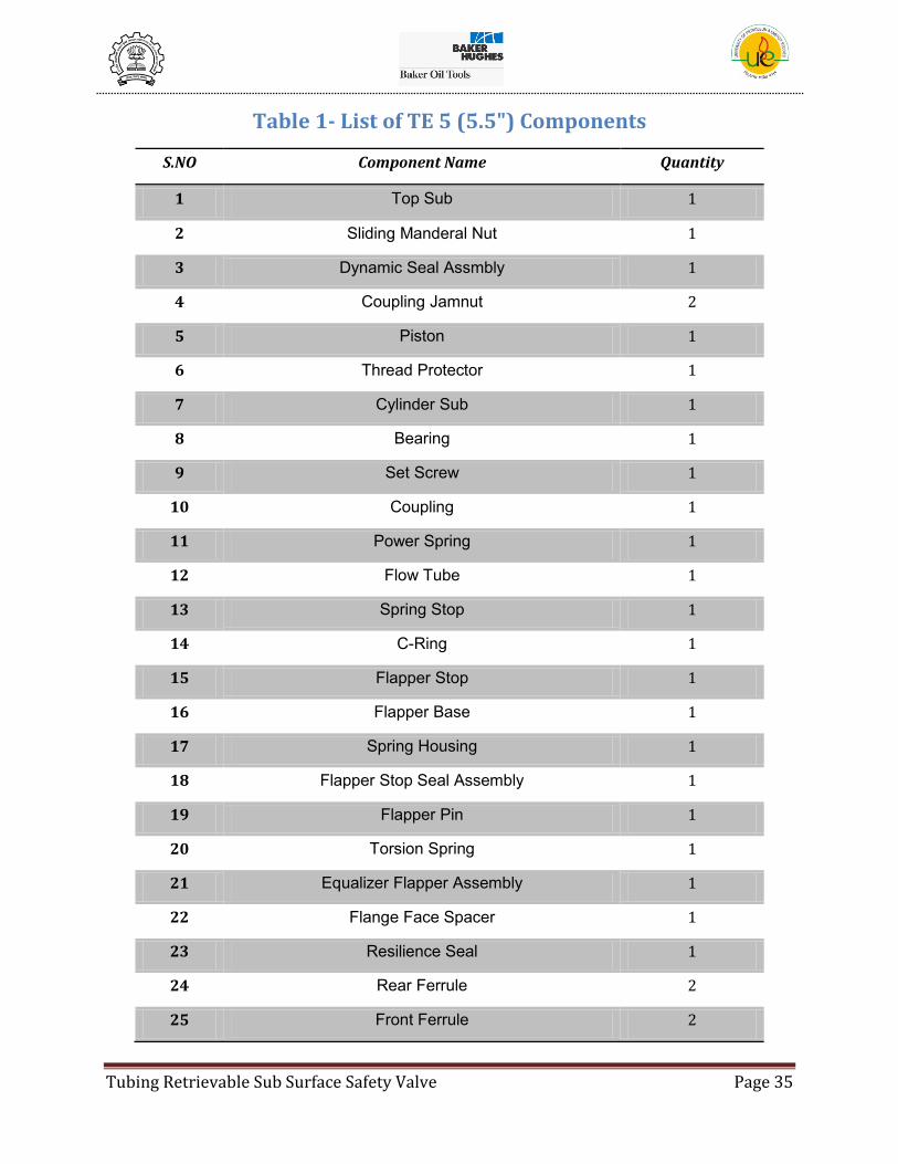
Table 1- List of TE 5 (5.5") Components
S.NO Component Name Quantity
1 Top Sub 1
2 Sliding Manderal Nut 1
3 Dynamic Seal Assmbly 1
4 Coupling Jamnut 2
5 Piston 1
6 Thread Protector 1
7 Cylinder Sub 1
8 Bearing 1
9 Set Screw 1
10 Coupling 1
11 Power Spring 1
12 Flow Tube 1
13 Spring Stop 1
14 C-Ring 1
15 Flapper Stop 1
16 Flapper Base 1
17 Spring Housing 1
18 Flapper Stop Seal Assembly 1
19 Flapper Pin 1
20 Torsion Spring 1
21 Equalizer Flapper Assembly 1
22 Flange Face Spacer 1
23 Resilience Seal 1
24 Rear Ferrule 2
25 Front Ferrule 2

Tubing Retrievable Sub Surface Safety Valve Page 36
8.2 Working of a TRSCSSV
The working principle for all TRSCSSV is same. These valves are controlled from the
surface via a small diameter hydraulic control line connecting the safety valve to the
surface Emergency Shut-Down System. Since the valve is of the normally closed type, when
the applied control line pressure is removed, the valve returns to the closed position thus
shutting in the well.
The control line is connected to the top sub through the jam nut connection. The control
line allows the control line fluid to fill inside the control chamber. The hydraulic oil used as
the control line fluid is used to pressurize the piston in the control chamber. The piston in-
turn pushes down the power spring. The piston is connected to the flow tube through
coupling thus allowing it to move down as the spring is compressed.
As soon as the flow tube comes in contact of the closed flapper, it pushes the plunger of the
equalizing port. The equalizing port allows the differential pressure across the flapper to
equalize. As soon as the differential pressure is equalized, the flow tube pushes down the
flapper to open position.
To again close the flapper, the pressure in the control line is bled off. This decompresses
the spring and the flow tube moves up. The flapper then closes and the metal to metal seal
doesn’t allow any fluid to pass through it. Thus the flow from the well is suspended and the
well is shut in.

Tubing Retrievable Sub Surface Safety Valve Page 37
8.3 Models Available
[Source: Baker Oil Tools Catalog]
Figure 8- Subsurface Safety Valve Type
Tubing Retrievable Sub Surface Safety Valve Page 38
CEMENTSAFE™ SERIES SUBSURFACE SAFETY VALVE
DESCRIPTION
The CEMENTSAFE™ Series tubing retrievable surface controlled subsurface safety valve is
designed specifically for use in cement-through and frac-through applications. In addition,
the CEMENTSAFE offers superior performance in applications that require the exclusion of
flowing debris from the working components of the TRSV.
The CEMENTSAFE utilizes a piston with non elastomeric dynamic seals to isolate the
control chamber and spring cavity from cement and produced fluids. This exclusion feature
not only protects the sealing surfaces of the actuation system but also excludes cement or
other debris from entering the flapper cavity of the safety valve.
The CEMENTSAFE incorporates the successful features from the T-Series™ product offering
such as metal-to-metal housing seals, metal-to-metal containment below the flapper, thru-
the-flapper self equalizing, and secondary puncture communication. This combination of
features ensures the performance required to meet the demands of harsh environments in
cement-through and frac-through applications.
FEATURES/BENEFITS
• Complete exclusion of well bore fluids from the spring and flapper cavity - Ensures
smooth and reliable operation in cement-through and frac-through applications
• Non elastomeric piston actuator system - elimination of elastomers and their inherent
problems
• Unique curved flapper - optimizes OD to ID relationships
• Metal-to-metal seal technology - 100% metal-to-metal sealing and containment of well
bore fluids when the valve is in the closed position
• Patented thru-the flapper equalizing system - most successful and widely used system
available to the market
• RBT Housing Seals - two step metal-to-metal sealing system provides strength and sealing
under the harshest conditions
• Patented radial punch control fluid communication system – eliminates accidental
communication primarily associated with linear shifting sleeves

Tubing Retrievable Sub Surface Safety Valve Page 39
Onyx™ SERIES SUBSURFACE SAFETY VALVES
DESCRIPTION
The Onyx™ Series, is the industry's first 7 in. tubing Retrievable Safety Valve (TRSV) that
can fit inside a 9-5/8 in. casing with cable bypass capabilities. In addition, Baker Oil Tools
has designed the industry's first 4-1/2 in. TRSV to fit inside a 7 in. casing.
The Onyx Series of tubing retrievable surface controlled subsurface safety valves are
specifically designed for big bore applications. Onyx Series safety valves are based on the
successful T-Series™. The Onyx Series combines a patented, state-of-the-art closure
mechanism and premium housing threads to produce the industry's first tubing retrievable
safety valves that offer full-opening production in smaller casing sizes. As a result,
operators get multiple benefits: the lower cost of smaller-OD casing, flexibility in designing
their completions, and higher production rates typical of larger tubing sizes.
FEATURES/BENEFITS
• Slimline OD - enables larger tubing to be installed without sacrificing the full opening for
maximized production
• Reduces completion cost (CAPEX) - the valve permits operators to use smaller casing
programs
• Broader application coverage - ability to run capillary lines for downhole instrumentation
or chemical injection and/or cables for electric submersible pump operation as well as dual
completion installations
• RBT Housing Seals - two step metal-to-metal sealing system provides strength and sealing
under the harshest conditions
• Non elastomeric dynamic seal assembly - withstands extreme pressures and
temperatures exceeding 28,000 psi and 450°F
• Metal-to-metal seal technology - 100% metal-to-metal sealing and containment of well
bore fluids when the valve is in the closed position
• Patented thru-the flapper equalizing system - most successful and widely used system
available to the market
Tubing Retrievable Sub Surface Safety Valve Page 40
• Ultra strong curved flapper design - resistant to high impact loads in high flow rate
applications

Tubing Retrievable Sub Surface Safety Valve Page 41
REALM™ SERIES SUBSURFACE SAFETY VALVE
DESCRIPTION
The new REALM™ Series tubing retrievable surface controlled subsurface safety valves are
specifically designed for high pressure / high temperature (HP/HT) applications. REALM
Series safety valves build upon the success of the T-Series™ and use state-of-the-art
technology to provide the industry's most reliable safety valve for these critical
applications.
The REALM Series reduces operating expenses by providing absolute pressure ratings. The
control chamber, dynamic seal system and rod piston are capable of withstanding full
differential pressures. This capability eliminates the requirement to stage tubing pressures
during installation, thus reducing installation cost and risk of over pressuring the valve.
Baker Oil Tools utilizes a unique design approach combining cutting edge design
techniques with the industry's most rigorous test program to provide safety valves
specifically designed for HP/HT applications.
FEATURES/BENEFITS
• Absolute pressure ratings - no staging of tubing pressure
• Non elastomeric dynamic seal assembly - withstands extreme pressures and
temperatures exceeding 28,000 psi and 450°F
• Metal-to-metal seal technology - 100% metal-to-metal sealing and containment of well
bore fluids when the valve is in the closed position
• Patented thru-the flapper equalizing system - most successful and widely used system
available to the market
• Ultra strong curved flapper design - designed to withstand extreme differential pressures
• RBT Housing Seals - two step metal-to-metal sealing system provides strength and sealing
under the harshest conditions
• HP/HT Leader - successful field experience minimizes operating risk
Tubing Retrievable Sub Surface Safety Valve Page 42
TITAN™ SERIES SUBSURFACE SAFETY VALVE
DESCRIPTION
Baker Oil Tools' commitment to innovation has resulted in the Titan™ Series surface
controlled subsurface safety valve. Innovative field-proven technology that reduces the
number of typical safety valve failure modes has been a hallmark of Baker Oil Tools' safety
valves through the years. Titan standard features include: wireline damage resistant
flapper, non elastomeric seal technology, and metal-to-metal containment of wellbore
fluids in the closed position. These standard features deliver unprecedented reliability,
efficiency, and adaptability.
One-quarter of all safety valve failures occur due to wireline damage during interventions
into the wellbore. The Titan incorporates the damage resistant characteristics of the
successful SelecT™ flapper design to virtually eliminate this failure mode. This design
ensures all seal surfaces are protected from wireline contact even during accidental closure
of the valve during wireline operations.
The Titan can be tailored to your specific needs, with available options such as integral
chemical injection capability, wireline damage resistant seal bores, and various control
system stop seal versions. An optional thru-the-flapper self equalizing system is also
available to minimize operational expenses while maximizing productivity.
FEATURES/BENEFITS
• Field-proven technology - basic design features have been carried over from the highly
successful T-Series™ and SelecT portfolios
• Patented thru-the-flapper self-equalizing - most successful and widely used system
available to the market
• Non elastomeric dynamic seal assembly - withstands extreme pressures and
temperatures exceeding 28,000 psi and 450°F
• Wireline damage resistant flapper - design protects sealing integrity during wireline
operations
• Patented lock open system - achieved via one wireline trip and allows flow through the
locked open valve with no ID restriction
Tubing Retrievable Sub Surface Safety Valve Page 43
• No shifting sleeves required to communicate - impossible to inadvertently communicate
the hydraulic chamber
• Metal-to-metal seal technology - 100% metal-to-metal sealing and containment of
wellbore fluids when the valve is in the closed position
• Optional chemical injection capability - injection mandrel within the TRSV eliminates the
need for a mandrel above the valve and allows injection of fluids directly into spring cavity
for maximum effectiveness
• Optional damage resistant seal bores - ensures seal bore integrity when it is needed
Tubing Retrievable Sub Surface Safety Valve Page 44
SelecT™ SUBSURFACE SAFETY VALVE
DESCRIPTION
The SelecT™ is a tubing retrievable surface controlled subsurface safety valve that is
designed to address the unique challenges that shallow set safety valves (typically <1,000 ft
) must endure. An ultra strong power spring delivers high closing forces needed to provide
reliable and consistent closings in the presence of paraffin and other produced solids.
One-quarter of all safety valve failures occur due to wireline damage during interventions
into the wellbore. The SelecT design team developed an advanced flapper design to
virtually eliminate this failure mode. This design ensures all seal surfaces are protected
from wireline contact even during accidental closure of the valve during wireline
operations.
Combining design enhancements with the successful features of the industry leading T-
Series™, the SelecT addresses applications for smaller tubing sizes ranging from 2-3/8 in. -
3-1/2 in.
FEATURES/BENEFITS
• Ultra strong power spring - ensures smooth and reliable closures
• Wireline damage resistant flapper - design protects sealing integrity during wireline
operations
• Patented thru-the-flapper self-equalizing - most successful and widely used system
available to the market
• Non elastomeric dynamic seal assembly - withstands extreme pressures and
temperatures exceeding 28,000 psi and 450°F
• Patented radial punch control fluid communication system – eliminates accidental
communication primarily associated with linear shifting sleeves
• Metal-to-metal seal technology - 100% metal-to-metal sealing and containment of
wellbore fluids when the valve is in the closed position
Tubing Retrievable Sub Surface Safety Valve Page 45
NEPTUNE™ SERIES NITROGEN-CHARGED SUBSURFACE SAFETY VALVE
DESCRIPTION
The Neptune™ Series nitrogen charged tubing retrievable surface controlled subsurface
safety valve is designed for completions requiring low operating pressures due to control
system limitations. The Neptune operating system contains many patented features that
provide simple, reliable, and fail-safe operation in the most critical applications.
The Neptune Series incorporates integral nitrogen charged systems within the valve, which
oppose the hydrostatic pressure acting on top of the piston. The dynamic seal configuration
used for the operating piston is a significant engineering achievement that utilizes the
industry's first non elastomeric seal technology for nitrogen charged safety valves. Unlike
other nitrogen charged designs, the Neptune Series' patented operating system is designed
to be fail-safe closed in all applications even if the primary nitrogen chamber pressure is
lost. The operating system is also far less susceptible to failing due to debris in the control
line or hysteresis as all ball check seats, Belleville washers, and collets have been
eliminated.
The Neptune Series comes standard with two totally independent operating systems and
an integral control line filter. These features deliver the redundancy and assurance
required in remote subsea wells. When it comes to your critical applications, the Neptune's
innovative design and simple operation make it the only logical choice to protect your
investment.
FEATURES/BENEFITS
• Two independent and operating systems - offers redundancy to maintain dependable
valve operation
• Simple operation - uses the same moving parts of a conventional TRSV
• Patented fail-safe operating system - ensures fail-safe operation in all applications
• Innovative non elastomeric seal technology - an industry first for nitrogen-charged valves
• Operating system is free of ball check seats - virtually eliminates failure due to control
line debris
• Low operating pressure at any setting depth - reduces operating system investment
Tubing Retrievable Sub Surface Safety Valve Page 46
• Optional integral control line filter - provides clean and trouble free operation
• RBT Housing Seals - two step metal-to-metal sealing system provides strength and sealing
under the harshest conditions.
Tubing Retrievable Sub Surface Safety Valve Page 47
TRITON™ SERIES BALANCE LINESUBSURFACE SAFETY VALVE
DESCRIPTION
The Triton™ Series balance line tubing retrievable surface controlled subsurface safety
valve is designed for completions requiring low operating pressures due to control system
limitations. The Triton combines the field-proven technology of the industry leading T-
Series™ with a hydrostatically balanced rod piston to achieve simple, reliable and fail-safe
operation.
Baker Oil Tools used a revolutionary design approach focusing on the elimination of
previous balance line failure modes. As a result, the Triton Series offers fail-safe operation
in every application. The non elastomeric rod piston design is also configured to make the
operating pressure insensitive to tubing pressure.
These design features are essential in providing a low-operating-pressure safety valve for
deepwater completions.
Failure to close due to the buildup of wellbore debris and in-service friction is one of the
most common failure modes of TRSV's. The Triton Series rod piston configuration is
designed to reduce the potential of this failure mode. Pressure can be applied to the
balance line to assist in closure if the valve is unable to close due to the buildup of debris
and additional friction.
Baker Oil Tools is committed to being the industry leader in offering versatile solutions for
demanding applications. The Triton Series teams with the Neptune™ Series and Titan™
Heavy Sprung designs to deliver reliable solutions for almost every deepwater/subsea
application.
FEATURES/BENEFITS
• Low operating pressure at any setting depth - reduces operating system investment
• Simple operation - uses the same moving parts of a conventional TRSV
• Patented fail-safe operating piston - previous balance line failure modes eliminated and
ensures fail-safe operation in all applications
• Non elastomeric dynamic seal assembly - withstands extreme pressures and
temperatures exceeding 28,000 psi and 450°F
Tubing Retrievable Sub Surface Safety Valve Page 48
• Patented thru-the flapper equalizing system - most successful and widely used system
available to the market
• RBT Housing Seals - two step metal-to-metal sealing system provides strength and sealing
under the harshest conditions
Tubing Retrievable Sub Surface Safety Valve Page 49
T-SERIES™ SUBSURFACE SAFETY VALVE
DESCRIPTION
Baker Oil Tools' T-Series™ tubing retrievable safety valves offer unmatched protection
from low end standard service through HP/HT applications. With T-Series Safety Valves,
one can count on premium performance and long-term reliability for the life of the well
which is attributed to complete removal of elastomeric compounds and elimination of
linear shifting sleeves. Incorporating non elastomeric dynamic seals and metal-to-metal
housing connections eliminates the possibility of explosive decompression which is
commonly associated with elastomeric compounds. Extensive studies by operators and
independent research institutes have shown that accidental actuation of shifting sleeves
and subsequent control fluid communication is one of the primary causes for safety valve
failures. By removing all shifting sleeves from the T-Series valve, Baker Oil Tools has
eliminated one of the most common failure modes found in safety valves.
The T-Series versatile design is ideal for a variety of applications including deepwater
completions. The T-Series Heavy Sprung Safety Valve features an extra strong power spring
to overcome the additional hydrostatic pressure associated with deep setting depths. The
reliability and simplicity of the T-Series have made it one of the most successful safety
valves in the industry. The high spring closure force guarantees performance in the
presence of paraffin or other produced solids.
FEATURES/BENEFITS
• Subsurface safety valve leader - successful field experience minimizes operating risk
• Non elastomeric dynamic seal assembly - withstands extreme pressures and
temperatures exceeding 28,000 psi and 450°F
• RBT Housing Seals - two step metal-to-metal sealing system provides strength and sealing
under the harshest conditions
• Patented radial punch control fluid communication system – eliminates accidental
communication primarily associated with linear shifting sleeves
• Patented thru-the flapper equalizing system - most successful and widely used system
available to the market
• Deep-set capability - ultra strong power spring ensures smooth and reliable closures

Tubing Retrievable Sub Surface Safety Valve Page 50
8.4 Models available in T-Series
There are various versions of T-Series safety valves available, depending upon the valve OD
and the rated working differential pressure.
The rated working pressure varies from 5000 psi to 13500 psi. The OD’s are available
ranging from 23/8 in. to 7 in.
In all, the different versions of T series can be broadly classified as follows:
T (E) Series
The Models “T(E)-5” and “T(E)-10” Tubing Retrievable Safety Valves are non-equalizing or
self equalizing flapper-type subsurface tubing mounted safety valves. The self-equalizing
version utilizes an Equalizing Flapper Assembly. The “TE-5” and “TE-10” are similar except
for rated working pressure. The “T (E)-5” is rated for 5,000 psi working pressure, and the
“T (E)-10” is rated for 10,000 psi.
TM (E) Series
The Model TM (E)-5 Tubing Retrievable Safety Valves are non-equalizing and self-
equalizing flapper-type subsurface tubing mounted safety valves rated for 5,000 psi
working pressure. The TM series valves utilize a redundant full open and full closed static
metal to metal seal on the dynamic actuator.
TSM (E) Series and TUSM (E) Series
The TSM (E) and TUSM (E) series have all the features of the TM (E) series and apart from
that they have a slim line outside diameter and ultra slim line outside diameter
respectively. These valves have a curved slim line flapper installed instead of a wedge
shaped flapper (present in T and TM series).
Curved shape of flapper allows for smaller O.D. of flapper housing or larger I.D. of flow tube
compared to wedge shape flapper valve.
Tubing Retrievable Sub Surface Safety Valve Page 51
Reduced O.D. or increased I.D. allows user more liberty in safety valve applications. A larger
diameter TRSV can be run inside casing that would normally require a down-sized tubing
string. A smaller pressure drop can be anticipated for a wireline valve application.
8.5 The Basic Hydrostatic Pressure Calculations
Hydrostatic pressure is created by the weight of a column of fluid. It is measured in psi or
pounds per square. It always acts on down-hole tools when they are run in liquids. There
can also be differences between the hydrostatic pressure in the annulus and tubing of a
well, due to the use of different weight fluids in the tubing and casing. Such differences can
elastically collapse or balloon, and therefore, lengthen or shorten; the tubing string.
Another example is the effect of hydrostatic pressure in the opening and closing of sub-
surface safety valves. The hydrostatic pressure or the tubing pressure opposes the opening
pressure of the safety valve and this, to open the safety valve; the opening pressure mist
offset the tubing pressure. Thus, the opening pressure of the valve is the tubing pressure +
normal opening pressure of the safety valve. In the closing of the safety valve, the
hydrostatic pressure or the tubing pressure actually helps to close the valve, due to the
hydrostatic force acting on the valve actuator’s hydraulic piston area.
Hydrostatic pressure has to be calculated using the fluid gradient. This number has the
units of psi/ft. Using data such as lbs/gal. Or API Gravity (if dealing with hydrocarbon
liquids), one can calculate the hydrostatic pressure by:
1) Finding the fluid gradient in the Packer Calculations Handbook
2) Multiplying this by the depth of interest.
8.6 Fail-Safe Setting Depth
The fail-safe setting depth of a single line control SCSSV is defined as the maximum setting
depth at which the valve will close while opposing the hydrostatic pressure in the control
line. The fail-safe depth of a SCSSV is dependent on numerous factors, such as force of the
power spring, actuator piston area, pressure gradient of the control line fluid and the
annulus fluid, as well as friction force developed when actuating the SCSSV.
Tubing Retrievable Sub Surface Safety Valve Page 52
For a particular SCSSV, the piston area and the spring force are constant, although the
setting depth may increase by adding additional spring force, the pressure gradient of the
control line fluid is the determining factor. If the annulus fluid is heavier than the control
line fluid, and there is a possibility that the control line could break, the hydrostatic
pressure applied at the working fail-safe setting depth, the theoretical depth should be
modified by a safety factor of 1.2 to 1.5 to compensate for potential increase in mechanical
and seal friction. Per API 14A, Fail-Safe Setting Depths are calculated with salt water in the
control line plus and an additional 15% is factored in, thus the actual Fail-Safe Setting
Depth of a valve is normally 28% greater with hydraulic oil in the control line.
Increased setting depths can be important for several applications:
In areas where it is desirable to place a safety valve below the level at which
paraffin/scales occur
In the arctic, where the safety valve should be installed below permafrost zone
In platform, subsea, or arctic applications, where it is desires to ensure that no hydrates
will form at the valve
In areas where the threat of earthquakes could cause tubing to leak below a shallow set
safety valve.
Fail-Safe Setting Depth Calculations
The fail-safe setting depth calculation is based on the condition that the control line parts at
the surface controlled subsurface safety valve and annulus fluid is introduced into the
control chamber.
The fail-safe setting depth calculation is a force balance of the vertically downward acting
forces and the vertically upward acting forces.
Downward Acting Forces
1. Hydrostatic Head = (Setting Depth x Hydraulic Gradient) x (Maximum Piston Area) =
(Sd)(g)(A)
2. Weight of Moving Parts = W
Tubing Retrievable Sub Surface Safety Valve Page 53
3. Accumulated Friction = This factor includes all sources of friction such as spring friction,
seal friction, flow tube friction, etc., and is to be determined from testing or good
engineering judgment = Ff.
Upward Acting Forces
1. Minimum Power Spring Force with Valve in Closed Position - Fs.
2. Forces = (Sd)(g)(A) + W + Ff - Fs = 0
Vertical Direction = 0
Therefore …
(Sd)(g)(A) + W + Ff = Fs
and …
Sd = (Fs - W - Ff)/(g)(A)(SF)
where:
SF = Safety factor, generally 1.15
Minimum and maximum fail-safe depths are to be determined, considering the variation in
spring valves as well as component tolerances.
Opening and Closing Pressure Calculations
The full opening pressure is to be calculated based upon the power spring(s) force in the
full open position and the associated dynamic friction.
The full open pressure calculation is based on the assumption that only the pump pressure
from the surface is available to open the valve. That is, this calculation ignores the
hydrostatic head in the control line. The full open pressure calculation is a force balance of
the vertically downward acting forces and the vertically upward acting forces.
Downward Acting Forces
1. Pump Pressure Force = (Full Open Press) x (Minimum Piston Area) = (Po)(A)
2. Weight of Moving Parts = W
Tubing Retrievable Sub Surface Safety Valve Page 54
Upward Acting Forces
1. Minimum Power Spring Force with Valve in Open Position - Fo
2. Accumulated Friction = This factor includes all sources of friction such as spring friction,
seal friction, flow tube friction, etc., and is to be determined from testing or good
engineering judgment = Ff.
Forces = (Po) (A) + W - Fo - Ft = 0
Vertical Direction = 0
Therefore:
(Po)(A) = Fo + Ft - W = 0
And
Po = (Fo + Ff- W)/ (A)
Minimum and maximum opening pressures are to be determined, considering the
variations in spring valves as well as component tolerances.
The full closed pressure is to be calculated based upon the power spring(s) force in the
fully closed position and the associated dynamic friction. The full closed pressure
calculation is a force balance of the vertically downward acting forces and the vertically
upward acting forces.
Downward Acting Forces
1. Pump Pressure Force = (Full Open Press) x (Minimum Piston Area) = (Pc)(A)
2. Weight of Moving Parts = W
3. Accumulated Friction = This factor includes all sources of friction such as spring friction,
seal friction, flow tube friction, etc., and is to be determined from testing or good
engineering judgment = Ff
Upward Acting Forces
1. Minimum Power Spring Force with Valve in Open Position = Fc
Forces = (Pc)(A) + W + Ff - Fc = 0
Vertical Direction = 0

Tubing Retrievable Sub Surface Safety Valve Page 55
Therefore
(Pc) (A) = Fc - Ft - W = 0
and
Pc = (Fc - Ff- W)/ (A)
Minimum and maximum opening pressures are to be determined, considering the
variations in spring valves as well as component tolerances.
Table 2- Fail Safe Setting Depth Calculations for the T (E) - 5 (5.5”) model (7)
Tubing Retrievable Sub Surface Safety Valve Page 56
8.7 Design Principles and Philosophy
Flow Tube Design Features
(4)The flow tube is the component which transfers the linear force of the piston to the
closure mechanism. The design of this component must withstand the large forces
imparted during slam closing the flapper mechanism and during opening the closure
mechanism against differential pressure. Furthermore, the flow tube functions to restrict
the migration of well debris into the spring cavity and therefore provides critical protection
of the dynamic seals.
Stress Considerations-
The Baker flow tube is designed to withstand the following stress conditions:
1. Column Buckling: It is caused by the force of the piston while opening the closure
mechanism against differential pressure. The critical buckling load must be greater
than actual buckling load (piston area of the dynamic system times the maximum
rated control line pressure).
2. Bearing Failure: It occurs between the contact surface of the bottom of the flow tube
and the upper face of the flapper while opening the closure mechanism against
differential pressure. The bearing stress (contact stress) between the bottom face of
the flow tube and the upper face of the non-self-equalizing flapper is kept below the
minimum yield strength of flow tube and flapper, whichever is less. Furthermore,
when considering the self equalizing flapper, the bearing stress kept below the
minimum yield strength of the flow tube and the plunger whichever is less. This
expectance criteria ensures that the flow tube will not swell or swedge and impede
the free movement of the component.
3. Pressure Induced combined Stress: It is due to the possibility of pressure build up
across the flow tube. It is calculated by the means of the combined stress, API burst
and collapse calculations and a collapse stability calculation. Analyzing these
features the ability of the flow tube to withstand differential pressure loads in very
unlikely situation, where debris may impede the ability of debris exclusion gaps

Tubing Retrievable Sub Surface Safety Valve Page 57
from venting pressure or in the event of very rapid pressurization or
depressurization of the tubing, is ascertained.
For Baker 5.5” TSM (E)-5:
Burst and Collapse pressure (Combine stress analysis) = 5000 psi
Burst Pressure (from API 5CT) = 4947 psi
Collapse pressure (from API 5CT) = 2175 psi
Collapse stability pressure across flow tube = 2542 psi
Debris Exclusion/Control Design Consideration:-
Baker applies two philosophies when designing a safety valve for service in the presence of
debris. The first is that the debris should be excluded from certain areas of the valve,
specifically the spring cavity; the second is that certain areas of the safety valve will be in
contact with debris and measures must be taken to prevent this debris from fouling the
mechanism with which it comes in contact.
Scale Deposition prevention:
Scale build up can be prevented by the use of following coatings:
Teflon-PTFE coating
Xylan
Here Xylan also referred as Poly-amid-imid type coating is best suited for acids, release,
abrasion, and high load bearing resistance. But Xylan doesn’t tolerates high pH, thus not
recommended for water based drilling mud, water based hydraulic control line fluid etc.
For high pH applications Teflon-PTFE should be considered.
Work in this field is still going and researchers are striving hard to fabricate a thinner
coating.
Flow Tube Closure Assist Tool
Because of the effectiveness of Baker’s Debris exclusion considerations, failures to close
and high opening pressure due to debris accumulation are minimized. In the event that
excessive debris or scale is realized, Baker can provide a wireline run, jar-activated, closure
assist tool. The three-trip tool sets in the lock profile provided in the safety valve nipple
adapter and incorporates a set of retraceable slips to engage and shift the flow tube both

Tubing Retrievable Sub Surface Safety Valve Page 58
upward and downward. Once the flow tube is freed, the closure assist tool is jarred-up to
release from the flow tube and is retrieved to the surface.
How side loading and torsional forces on a rod piston are perceived and designed for-
Baker’s philosophy in this regard is the same used throughout the design of T-Series safety
valves:
Wherever possible, either eliminate undesirable phenomenon.
Make the mechanism affected by those phenomenons rugged enough to withstand
them.
Rather than incorporate additional mechanisms to protect weak points.
Eccentric loading of the flow tube by the single piston located offset from the valve’s
centerline, has two detrimental effects.
It causes resultant side loads at the points at the either end of the flow tube where the flow
tube is guided by the cylinder sub and the spring washer. This side loading can result in
excessive friction and wear at these points. This is addressed in the TM and TSM safety
valve by special surface treatments and coatings on these sliding surfaces.
The second effect is a bending moment applied to the flow tube between the two guide
points. Many valves have a two-piece flow tube which can flex at the connection between
the two pieces, substantially exaggerating the friction and wear. The TM and TSM have a
robust, one-piece flow tube which is stiff enough to be unaffected by the applied bending
moment.
Torsional Loading of the rod piston can result from the rotation of the flow tube caused by
the compression of the helical power spring. Other manufacturers address this by:
1. Adding rotational lock mechanisms to prevent the rotation of the flow tube.
2. Bearing systems to absorb the rotation at the end of the power spring
In earlier designs, Baker used this approach as well. However, these mechanisms add to
the complexity of the valve and introduce additional, unnecessary failure modes.
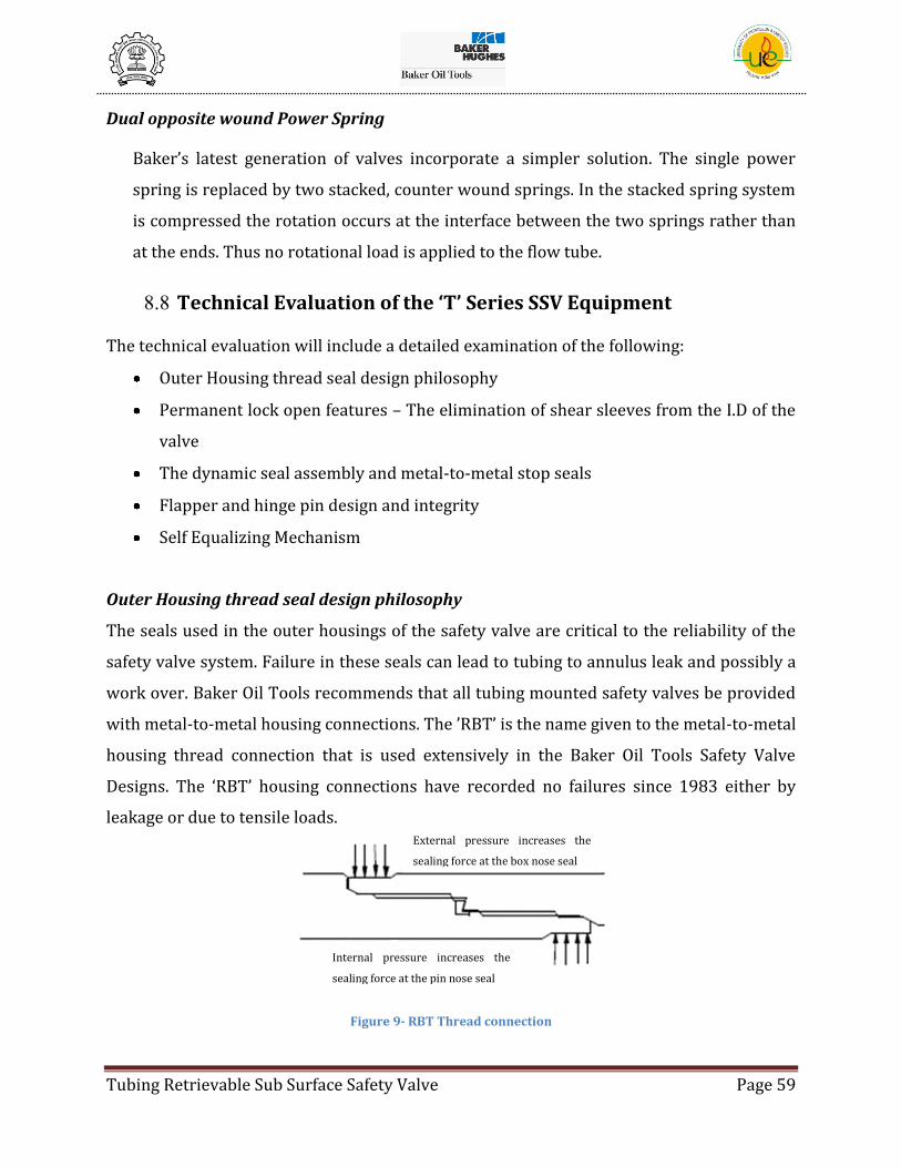
Tubing Retrievable Sub Surface Safety Valve Page 59
Dual opposite wound Power Spring
Baker’s latest generation of valves incorporate a simpler solution. The single power
spring is replaced by two stacked, counter wound springs. In the stacked spring system
is compressed the rotation occurs at the interface between the two springs rather than
at the ends. Thus no rotational load is applied to the flow tube.
8.8 Technical Evaluation of the ‘T’ Series SSV Equipment
The technical evaluation will include a detailed examination of the following:
Outer Housing thread seal design philosophy
Permanent lock open features – The elimination of shear sleeves from the I.D of the
valve
The dynamic seal assembly and metal-to-metal stop seals
Flapper and hinge pin design and integrity
Self Equalizing Mechanism
Outer Housing thread seal design philosophy
The seals used in the outer housings of the safety valve are critical to the reliability of the
safety valve system. Failure in these seals can lead to tubing to annulus leak and possibly a
work over. Baker Oil Tools recommends that all tubing mounted safety valves be provided
with metal-to-metal housing connections. The ’RBT’ is the name given to the metal-to-metal
housing thread connection that is used extensively in the Baker Oil Tools Safety Valve
Designs. The ‘RBT’ housing connections have recorded no failures since 1983 either by
leakage or due to tensile loads.
Figure 9- RBT Thread connection
External pressure increases the
sealing force at the box nose seal
Internal pressure increases the
sealing force at the pin nose seal
Tubing Retrievable Sub Surface Safety Valve Page 60
The box and pin sealing lips at each end of the thread (box and pin noses) are designed
with interference that provides a positive metal-to metal seal for containment of both
internal and external pressure.
The 'RBT' thread has a center locating shoulder that carries the torque of the made up
connection. The torque capacity of the connection is defined by the bearing area of this
shoulder. Experience has shown that this design provides excellent resistance to back off in
down-hole service.
This center locating shoulder also provides the proper metal-to-metal interference for the
seals at the box and pin noses. The pressure holding ability of the 'RBT' is not a direct
function of makeup torque. The pressure holding ability of the thread is defined by the
interference at the box and pin noses.
Permanent Lock Open Features
Important: In 1992 (25%) twenty five percent of tubing retrievable safety valve failures in
an independent study were caused directly by leakage between the hydraulic control line
chamber and the tubing well bore through the wireline insert valve communication feature.
One out of ever four failures was linked to a communication feature in the I.D. of the valve.
No matter how strong the shear sleeves in the Safety valves were wireline operators and
coil tubing units managed to find a way to prematurely shear any type of shear sleeve that
has been placed in a Safety Valve I.D.
Baker Oil Tools redesigned the permanent lock open feature for the 'T' series valves. The
sleeves that were shearing prematurely were completely eliminated from the I.D. of the
valve. There have been no recorded failures of the Baker puncture communication system
causing a premature leak or failure. There are no shear sleeves in the I.D. of the 'T' series
safety valves.
Evaluation of dynamic seal assembly and metal-to-metal stop seals
The use of rod piston type actuators reduces the number of possible leak paths, the friction
is reduced from the old style concentric piston designs (much smaller circumference) and
deeper setting depths are easier to achieve.
The dynamic actuator seal assemblies are designed to last the Test that each design is
required to complete – the Baker Endurance Test and/or Cyclic Hot Test, involves more

Tubing Retrievable Sub Surface Safety Valve Page 61
than 1200 cycles. This duplicates opening and closing the valve once a month for the next
100 years. The valve and control fluid temperature are also cycled. The temperature is
varied throughout the test from 100 F to the maximum rated temperature of the valve.
The dynamic seals used in the 'T' series valves have been proven with the metal to metal
stop seal design as well as the 'standard' non elastomeric assembly that does not utilize the
metal to metal stop seals.
Figure 10- Dynamic Seal Assembly
Components of dynamic seal assemblies and metal-to-metal stop seals:
The Baker Oil Tools system uses the following main components.
The dynamic seal assembly
The full open metal to metal stop seal
The full closed metal to metal stop seal
The detent / dampener system
Location of the Metal to Metal stop seals
The Baker metal to metal seat is made from MP159 material. This highly corrosion
resistant material provides the highest degree of sealing integrity.
The location of the metal to metal stop seals when the valve is in the full closed position is
an interesting discussion. Typically there are two choices. First-locating the seal in the
control line fluid or second - locating the seal at a point below the seal bore and other seals.
The arguments for each are given below:
Locating the 'full closed stop seal' inside the control line chamber

Tubing Retrievable Sub Surface Safety Valve Page 62
The advantage of the internal full closed stop seal is that the metal to metal seat is
'protected' by the hydraulic fluid - during the time that the valve is in the open position the
seat is bathed in control fluid.
The disadvantage of the internal closed stop seal is that the importance is placed on the
making sure that the full closed metal to metal seat (static seal) is protected. It ignores the
fact that the seal bore may be subject to increased corrosion, pitting and scale during the
time that the valve is in the closed position. If this type of corrosion begins it will be very
hard on the dynamic seal assembly. The corrosion generally forms a very rough surface and
will destroy the dynamic seal over time.
Figure 11- Location of Metal to Metal Stop Seal

Tubing Retrievable Sub Surface Safety Valve Page 63
Baker Oil Tools' Detent System for the 'T'-Series Safety Valves
The purpose of the detent spring system is to prevent the deformation of the two mating
metal-to metal surfaces during slam closures of the valve. During slam closures the impact
of the flow tube and piston being pushed into the metal to metal seat can render the metal
to metal stop seal ineffective. The impact is softened and any damage to the two surfaces is
eliminated by the use of the shock absorber (detent / dampener system). If the valves that
you are comparing do not have a detent system it is likely that the metal-to-metal seals will
be ineffective.
Figure 12- Detent System/Shock Absorber
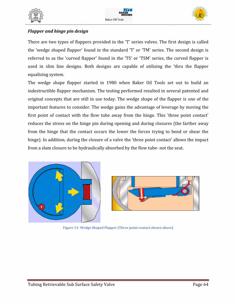
Tubing Retrievable Sub Surface Safety Valve Page 64
Flapper and hinge pin design There are two types of flappers provided in the 'T' series valves. The first design is called
the 'wedge shaped flapper' found in the standard 'T' or 'TM' series. The second design is
referred to as the 'curved flapper' found in the 'TS' or 'TSM' series, the curved flapper is
used in slim line designs. Both designs are capable of utilizing the 'thru the flapper
equalizing system.
The wedge shape flapper started in 1980 when Baker Oil Tools set out to build an
indestructible flapper mechanism. The testing performed resulted in several patented and
original concepts that are still in use today. The wedge shape of the flapper is one of the
important features to consider. The wedge gains the advantage of leverage by moving the
first point of contact with the flow tube away from the hinge. This 'three point contact'
reduces the stress on the hinge pin during opening and during closures (the farther away
from the hinge that the contact occurs the lower the forces trying to bend or shear the
hinge). In addition, during the closure of a valve the 'three point contact' allows the impact
from a slam closure to be hydraulically absorbed by the flow tube- not the seat.
Figure 13- Wedge Shaped Flapper (Three point contact shown above)

Tubing Retrievable Sub Surface Safety Valve Page 65
Table 3- Features and Benefits of Wedge Shape Flapper
Features Benefits
Only two parts move to fully open the safety
valve
Simplicity in design relates directly to long life
operation. Once open, the closure mechanism is
out of the flow path and completely covered by
the flow tube.
Wedge shape flapper
By moving the initial flow tube contact point
away from the hinge pin, the wedge shape
assures the largest moment arm possible during
flapper opening and closing. This reduces hinge
and pin stresses to the very minimum.
Stainless or nickel steel flapper, machined from
solid bar
Stronger and more ductile than cast materials:
wider variety of suitable materials available in
bar form. Greater assurance of uniformity of
properties and overall quality of flapper
Dual hinge flapper Flapper pin is loaded in double shear only. Pin is
not subject to bending loads.
Large diameter, high strength hinge pin
Assures maximum shear resistance available to
resist damage over lifetime of valve. Premium
corrosion resistant material (MP35N) provides
unlimited down-hole life expectancy.
Single wire torsion spring
Torsion spring returns flapper to full closed,
sealing position without any assistance from
well pressure. Torsion spring is wound around
mid section of hinge pin, thus maximizing the
quantity of wire available for the given flapper.
Wedge shape flapper mechanism proven
repeatedly in high velocity gas slam testing
Baker was the first safety valve company to
subject a closure mechanism to repeated slam
closures without failure of the components.
The curved flapper also has the 'three point contact' advantage. The curved flapper allows
the sides to contact the flow tube before the flapper engages the seat. . The valve seat is

Tubing Retrievable Sub Surface Safety Valve Page 66
thus protected from damage due to stress so it will seal as effectively the next time.
Figure 14- Curved Flapper Design
Both systems utilize the concept of placing the hinge pin in shear rather that to place it in
bending. The hinge pin is manufactured of specially selected high-strength alloy. And
because of the unique hinge design, the hinge pin bending common in other valves is
completely eliminated.
Table 4- Features and Benefits of Curved (Slim line) Flapper
Features Benefits
Curved shape of flapper allows for
smaller O.D. of flapper housing
and/or larger I.D. of flow tube
compared to wedge shape flapper
valve.
Reduced O.D. / increased I.D. allows user more latitude in
safety valve applications. A larger diameter TRSV can be run
inside casing that would normally require a down-sized
tubing string. A smaller pressure drop can be anticipated for
a wireline valve application.
Unique geometry of flapper assures
only axial loads are transmitted to
the flow tube.
Flow tube is not bent or crimped by radial loads from the
flapper during opening and closing. This eliminates damage
which may cause wireline tool strings to hang-up in the valve.
Curved and angled seating surface
is not intersected by flow tube
during opening or closing.
Eliminates wear on sealing surfaces which would eventually
cause leakage.
Tight tolerance held on hinge and
pin components.
Eliminates use of external alignment devices that add friction
and complexity to the closure mechanism. This is the same,

Tubing Retrievable Sub Surface Safety Valve Page 67
proven philosophy used for the Baker wedge shape flapper
closure mechanism.
Sculptured flapper geometry.
Reduces inertial forces which come into play during slam
opening/closing of valve. Efficient, compact design.
Primary metal-to-metal flapper to
seat seal is backed-up by a resilient
seal on the flapper seat.
Torsion spring returns flapper to full closed, sealing position
without any assistance from well pressure. Torsion spring is
wound around mid section of hinge pin, thus maximizing the
quantity of wire available for the given flapper.
Both systems utilize the concept of placing the hinge pin in shear rather that to place it in
bending. The hinge pin is manufactured of specially selected high-strength alloy. And
because of the unique hinge design, the hinge pin bending common in other valves is
completely eliminated.
Figure 15- Single Hinge Flapper Assembly

Tubing Retrievable Sub Surface Safety Valve Page 68
Gas slam test
A gas slam test is designed to duplicate the condition when a well is flowing, the control
line is bleed off and the safety valve closes with the flow against the flapper. Gas slam test
are an excellent indication of the reliability of a subsurface safety valve. API test require
only the very minimum requirements regarding slam test. Baker Oil Tools has designed
flappers that are virtually indestructible and this allow the valves to be tested at flow rates
and velocities listed below.
These test represent real life conditions and need to be considered when evaluating
Subsurface safety valves. All sizes of 'T' series valves have complete High Velocity Gas Slam
Test 20 Slams, 15 of which are:
200 ft/sec (41 MMSCFD)for 2-3/8" Valves
200 ft/sec (58.5 MMSCFD)for 2-7/8" Valves
200 ft/sec (102.7 MMSCFD)for 3-1/2" Valves
150 ft/sec (146.0 MMSCFD)for 4-1/2" Valves
125 ft/sec (120.7 MMSCFD)for 5-1/2" Valves
The Post slam leak rate following the slam test is the same leak rate that is required by the
API 14A functional test for 'new' valves.
Self-Equalizing Mechanism
A Self-Equalizing Safety Valve contains an integral equalizing mechanism which allows
shut-in pressure from below the safety valve to be vented to the tubing above the flapper.
This will decrease the differential pressure across the flapper (equalize) and allow the
valve to open. There is no need to fill the tubing above the flapper with fluid, hook-up a
pump to pressure down the tubing above the flapper to equalize the pressure across the
flapper. The self- equalizing system will equalize the valve and have the well back on
production quicker, safer and more efficiently. The simplicity and advantages of being able
to open a valve without having to mobilize pumps and fluids that are required to equalize a
non self-equalizing valve have made a tremendous market for self –equalizing valves. The
economics generally provide that a self -equalizing system will pay for itself in a matter of a
few months. In some applications the system pays for itself the first time that it is used.

Tubing Retrievable Sub Surface Safety Valve Page 69
Wide spread use of self equalizing valves is the industry standard. One of the main reasons
for the success is the system described below.
Evaluation of Self-Equalizing Designs
There are basically two types of self equalizing systems.
1) Around the flapper
2) Thru the Flapper
The major disadvantage of 'around the flapper' type self-equalizing mechanisms is that
produced fluids containing debris, such as scale and sand, are introduced into the annulus
created between the valve's flow tube and outer housing. There is a tendency for the debris
to collect in the annulus of the valve and eventually block the movement of the flow tube as
it tries to return to the closed position. Valves that use 'around the flapper' equalizing
systems can fail in the "open" position due to the problems associated with the location of
this debris! Erosion problems are also a concern and can lead to leakage. The Baker Oil
Tools thru the flapper system is good for the working pressure of the valve that it is used
on. We have several systems rated above 10,000 psi.
Baker Oil Tools patented "THRU-THE FLAPPER, METAL-TO-METAL, SELF-EQUALIZING
SYSTEM" type equalizing system was developed to eliminate problems. The result is the
most popular, reliable equalizing system in the industry.
OPERATION
Simple opening procedure - Close the wing valve -then pressure up to the valve full opening
pressure. The equalizing feature will allow the pressure to equalize and open the safety
valve. The equalizing feature does not interfere with normal valve operations. After the
Subsurface safety valve is open, open the wing valve and flow the well as required. The
process is quick and simple. No staggering pressures or worries about damaging the valve.
This allows the wells to be put on production much sooner after a system test on
emergency shut-down, the increased production could pay for the feature the first time it is
used.
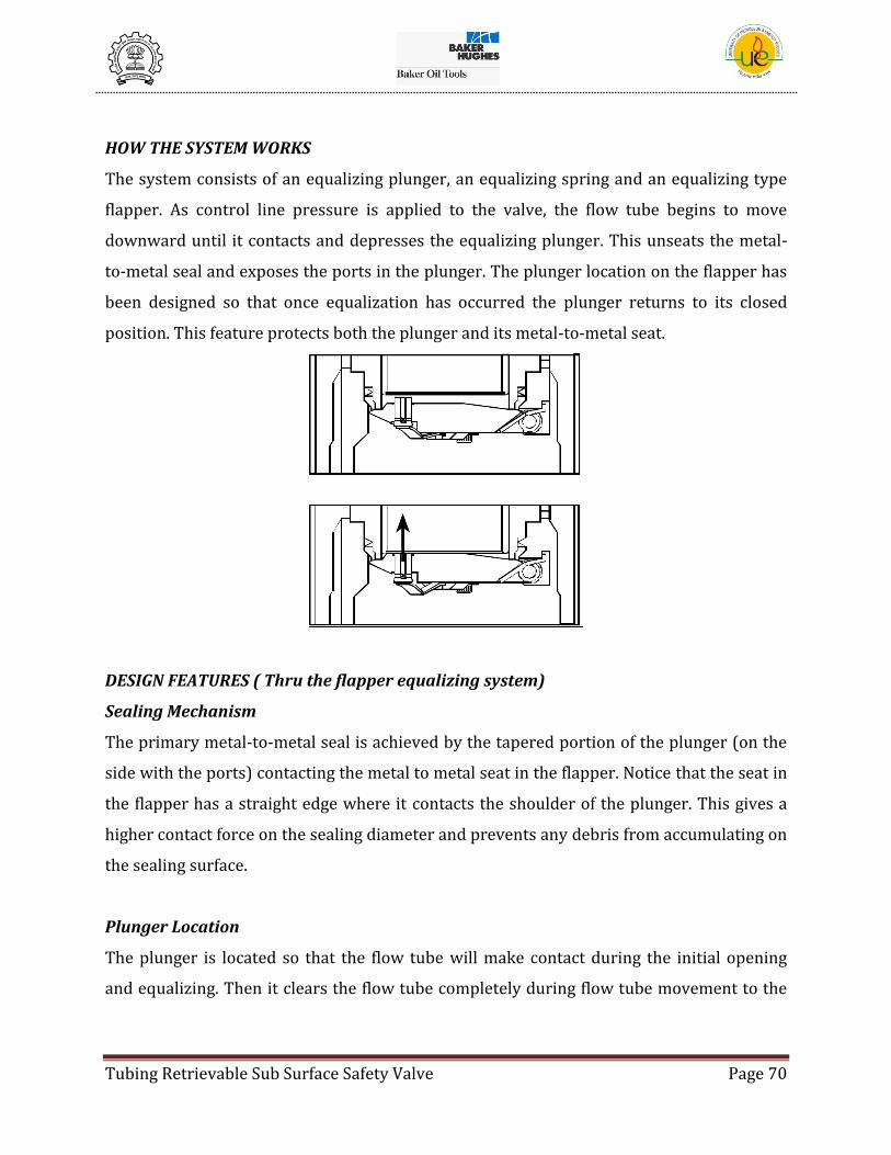
Tubing Retrievable Sub Surface Safety Valve Page 70
HOW THE SYSTEM WORKS
The system consists of an equalizing plunger, an equalizing spring and an equalizing type
flapper. As control line pressure is applied to the valve, the flow tube begins to move
downward until it contacts and depresses the equalizing plunger. This unseats the metal-
to-metal seal and exposes the ports in the plunger. The plunger location on the flapper has
been designed so that once equalization has occurred the plunger returns to its closed
position. This feature protects both the plunger and its metal-to-metal seat.
DESIGN FEATURES ( Thru the flapper equalizing system)
Sealing Mechanism
The primary metal-to-metal seal is achieved by the tapered portion of the plunger (on the
side with the ports) contacting the metal to metal seat in the flapper. Notice that the seat in
the flapper has a straight edge where it contacts the shoulder of the plunger. This gives a
higher contact force on the sealing diameter and prevents any debris from accumulating on
the sealing surface.
Plunger Location
The plunger is located so that the flow tube will make contact during the initial opening
and equalizing. Then it clears the flow tube completely during flow tube movement to the
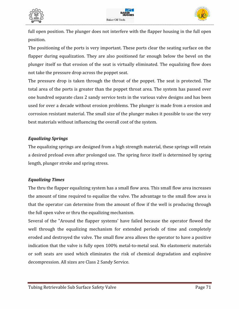
Tubing Retrievable Sub Surface Safety Valve Page 71
full open position. The plunger does not interfere with the flapper housing in the full open
position.
The positioning of the ports is very important. These ports clear the seating surface on the
flapper during equalization. They are also positioned far enough below the bevel on the
plunger itself so that erosion of the seat is virtually eliminated. The equalizing flow does
not take the pressure drop across the poppet seat.
The pressure drop is taken through the throat of the poppet. The seat is protected. The
total area of the ports is greater than the poppet throat area. The system has passed over
one hundred separate class 2 sandy service tests in the various valve designs and has been
used for over a decade without erosion problems. The plunger is made from a erosion and
corrosion resistant material. The small size of the plunger makes it possible to use the very
best materials without influencing the overall cost of the system.
Equalizing Springs
The equalizing springs are designed from a high strength material, these springs will retain
a desired preload even after prolonged use. The spring force itself is determined by spring
length, plunger stroke and spring stress.
Equalizing Times
The thru the flapper equalizing system has a small flow area. This small flow area increases
the amount of time required to equalize the valve. The advantage to the small flow area is
that the operator can determine from the amount of flow if the well is producing through
the full open valve or thru the equalizing mechanism.
Several of the "Around the flapper systems' have failed because the operator flowed the
well through the equalizing mechanism for extended periods of time and completely
eroded and destroyed the valve. The small flow area allows the operator to have a positive
indication that the valve is fully open 100% metal-to-metal seal. No elastomeric materials
or soft seats are used which eliminates the risk of chemical degradation and explosive
decompression. All sizes are Class 2 Sandy Service.
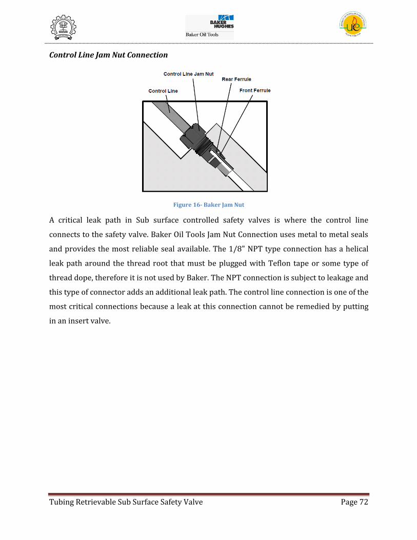
Tubing Retrievable Sub Surface Safety Valve Page 72
Control Line Jam Nut Connection
Figure 16- Baker Jam Nut
A critical leak path in Sub surface controlled safety valves is where the control line
connects to the safety valve. Baker Oil Tools Jam Nut Connection uses metal to metal seals
and provides the most reliable seal available. The 1/8" NPT type connection has a helical
leak path around the thread root that must be plugged with Teflon tape or some type of
thread dope, therefore it is not used by Baker. The NPT connection is subject to leakage and
this type of connector adds an additional leak path. The control line connection is one of the
most critical connections because a leak at this connection cannot be remedied by putting
in an insert valve.

Tubing Retrievable Sub Surface Safety Valve Page 73
Debris and Sand exclusion barriers
Figure 17- Debris and Sand Exclusion Barriers
The T-series valves have a simple and effective method of preventing sand or debris from
entering the area behind the flow tube or around the flapper seat. As shown in the above
illustrations there is a close tolerance barrier at the top of the spring cavity and also one
towards the bottom of the spring cavity. These are controlled tolerances that are designed
to keep sand and debris out. These are not seals or wipers, but they do prevent any flow
around the flow tube. A small amount of fluid must pass through these barriers due to the
change in volume in the spring cavity caused by the piston / actuator moving up and down
as the valve opens and closes.
The T-series valves are all tested with sand slurries and are tested to the standards of the
API 14A class 2 sandy service test.

Tubing Retrievable Sub Surface Safety Valve Page 74
8.9 ‘T’ Series accessory tools
Flapper Lock Open Tool
(7)The Flapper Lock Open Tools allows retrieval of a Dry String. Flapper Lock
Open is also used in the event of Safety Valve malfunction. After the Safety Valve
has been permanently locked open, it may accept a Separation Sleeve or a
Wireline Retrievable Insert Safety Valve provided communication of the control
fluid to the interior of the valve has also been accomplished.
Two wireline runs are required to permanently lock the Flapper of a Tubing
Retrievable Valve open. On the first run, the Flapper Lock Open Tool is landed and
locked in the Nipple Profile of the Tubing Retrievable Safety Valve. Withdrawal of
the Wireline Running Tool which is attached to the Slide Assembly portion of the
Flapper Lock Open Tool actuates the Tool releasing the Lock Ring, which retains
the Flapper in the open position. A second run retrieves the Flapper Lock Open
Tool. The tool is designed such that the Lock Ring cannot be released into the
Flapper section if the Flow Tube of the Tubing Retrievable Safety Valve is not in
the fully closed position.
Figure 18- Flapper Lock Open Tool
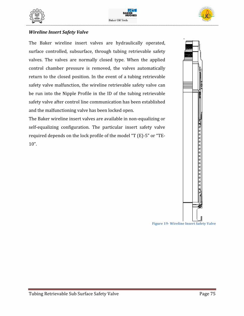
Tubing Retrievable Sub Surface Safety Valve Page 75
Wireline Insert Safety Valve
The Baker wireline insert valves are hydraulically operated,
surface controlled, subsurface, through tubing retrievable safety
valves. The valves are normally closed type. When the applied
control chamber pressure is removed, the valves automatically
return to the closed position. In the event of a tubing retrievable
safety valve malfunction, the wireline retrievable safety valve can
be run into the Nipple Profile in the ID of the tubing retrievable
safety valve after control line communication has been established
and the malfunctioning valve has been locked open.
The Baker wireline insert valves are available in non-equalizing or
self-equalizing configuration. The particular insert safety valve
required depends on the lock profile of the model “T (E)-5” or “TE-
10”.
Figure 19- Wireline Insert Safety Valve
Tubing Retrievable Sub Surface Safety Valve Page 76
Separation Sleeve
The purpose of the Separation Sleeve is to blank-off the hydraulic chamber in a “T-Series”
Safety Valve after control line communication has been established between the control
line and the valve ID, to prevent contamination of the control line by well fluids. After
control line communication has been established, well pressure can communicate to the
surface through the control tubing until a Separation Sleeve or other appropriate wireline
tool is run into the Nipple Profile in the “T-Series” Safety Valve.
The Separation Sleeve should be used if control line communication has been established
and production of the well is scheduled to continue without an operable safety valve in the
well. The use of a Separation Sleeve is also recommended when pulling the string after
control line communication has been established.
The particular Separation Sleeve required depends on the Lock Profile of the Safety Valve.
The Flapper Lock Open Tool opens the Tubing Safety Valve and maintains it in that position
when the tubing is pulled, permitting retrieval of dry string. It is also run in the event of
Tubing Ret. Safety Valve malfunction. When the Safety Valve has been permanently locked
open, it will accept a Separation Sleeve or Wireline Insert Valve.
A separate Flapper Lock Open is required for each of the various lock profiles available for
the Tubing Retrievable Safety Valve.

Tubing Retrievable Sub Surface Safety Valve Page 77
Control Pressure Communication Tool
The Control Pressure Communication Tool is used to establish control line communication
into tubing retrievable safety valves containing the control line communication feature by
no-going into a Lock Profile. This enables the use of a control line actuated wireline insert
safety valve. A separate Control Pressure Communication Tool is required for each of the
various lock profiles available for the Tubing Retrievable Safety Valve.
Figure 20- Control Pressure Communication Tool
Tubing Retrievable Sub Surface Safety Valve Page 78
9. CONCLUSION
1. Stringent testing procedures are followed for the working of a TRSCSSV since it
stays in the well till the well lasts and can be in operation at any point of time.
2. Advancement in Design can be done by improvement of piston features and a
cylindrical piston again be looked upon as a possibility since it will eradicate the
problems of torsional loading, column buckling, flexing, eccentric loading and other
complexities in the design.
3. The TRSCSSV generally fails due to breaking up of the control line due to various
reasons. Thus a design which has no control line is being looked for which has
probably some other working mechanism, though no work has yet been done on it.
Tubing Retrievable Sub Surface Safety Valve Page 79
10. BIBLIOGRAPHY
1. BakerHughesDirect. About Baker Hughes. [Online] [Cited: July 20, 2008.]
http://www.bakerhughesdirect.com/cgi/bhi/resources/ExternalFileHandler.jsp?path=pri
vate/BHI/public/bakerhughes/about/index.html&bookmarkable=Yes&channelId=-
3000081. ISO-8859-1.
2. Baker Hughes - Investor Relations - Financial Highlights. Baker Hughes Direct. [Online]
[Cited: July 20, 2008.] http://investor.shareholder.com/bhi/financials-KeyRatios.cfm. UTF-
8.
3. About Baker Oil Tools. Baker Hughes - Baker Oil Tools. [Online] [Cited: July 20, 2008.]
http://www.bakerhughesdirect.com/cgi/bot/resources/ExternalFileHandler.jsp?path=pri
vate/BOT/public/about/index.html&bookmarkable=Yes&channelId=-
4198841&channelId=-4198841. ISO-8859-1.
4. Monica Wolf. Course 023 - Subsurface Safety Systems. IMPACT Module 023. 1999.
5. maxerhim. Catalog SSBOT-04-5809. Safety Systems. s.l. : Baker Oil Tools, 2004.
6. Perrin, D. Well Completion and Servicing. Paris : Technip, 1999. pp. 153-160.
7. Baker Oil Tools. Model T(E)-5 Deep Set Tubing Retrievable Flapper (5.5") Tech Unit. B-
153-5. 2003.