Scrubber Designs For Hard Chrome Plating - InfoHouseinfohouse.p2ric.org/ref/23/22322.pdf ·...
19
and
Transcript of Scrubber Designs For Hard Chrome Plating - InfoHouseinfohouse.p2ric.org/ref/23/22322.pdf ·...

and
I.
SCRUBBER DESIGNS FOR HARD CHROME PLATING Frank B. Power
William M. Schott Kimre, Inc.
Perrine, Florida
8BSTRACT
Emission control in the chrome plating industry has seen an evolution in regulation. This has resulted in an evolution in the gas-cleaning or scrubbing technologies employed. Packed bed scrubbers and chevron eliminators offer reasonable efficiencies down to 8-15 micron droplets. Knitted-mesh mist eliminators were able to improve efficiencies even further.
With the adoption of more stringent emission limits by California and other regional air resource boards, a uniquely interlaced monofilament structure has been proven to meet those strict limits in a cost-effective manner. Systems designed using this interlaced monofilament structure achieve efficiencies of 99+% on droplets of one micron and larger. This paper discusses the changes in scrubbing technology in the plating industry and describes various design ideas and technologies behind systems utilizing this interlaced monofilament structure.
11. JN TRODUCTION
There are many types of scrubber or gas-cleaning equipment. Generic types, along with their mechanisms of collection, are considered. Fiber-type scrubbers and an advanced design using uniquely interlaced monofilaments with a specific geometric orientation are considered in more detail. This will illustrate the design methods for successful scrubber operations.
The emissions standards might be set, the operating limits might be set as far as water balance or space; however, the DESIGN parameters are really not set. The actual size distribution of droplets to be collected is not known, nor is a reasonable method to generate the size distribution known. This makes the comparison of alternatives extremely difficult.
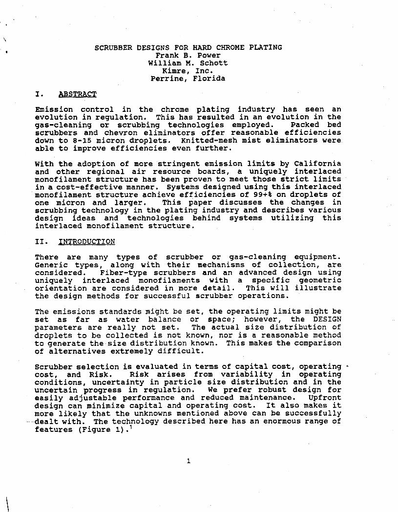
Scrubber selection is evaluated in terms of capital cost, operating - cost, and Risk. Risk arises from variability in operating conditions, uncertainty in particle size distribution and in the uncertain progress in regulation. We prefer robust design for easily adjustable performance and reduced maintenance. Upfront design can minimize capital and operating cost. It also makes it more likely that the unknowns mentioned above can be successfully dealt with. The technology described here has an enormous range of features (Figure 1) .'
1

One researcher has remarked that separation costs go up by a factor
a factor l o o 2 All the more reason for good, flexible design. * of 10 when the size of the droplets to be eliminated decreases by
111.
In hard and decorative plating, the object to be plated is placed in a bath with a chromic acid solution. The object is then connected at the negative electrode of an electrolytic cell. When a voltage is placed across the cell, chromium is deposited on the object.
However, as a side reaction, water in the plating solution decomposes to oxygen and hydrogen. As those gases rise to the surface, the gas bubbles burst creating chromic acidmist droplets.
These droplets are collected in hoods and exhausted to control devices like scrubbers. The exhaust airflow is then emitted into the atmosphere. 3
Traditionally scrubbers are one or more pieces of equipment that provide :
1. Contact of a gas and an aqueous solution to absorb gases (vapor), and/or assist the collection of particulates (mist or dust).
2 . Separation of the aqueous and collected particle from the treated gas.
Examples of such traditional scrubbers are:
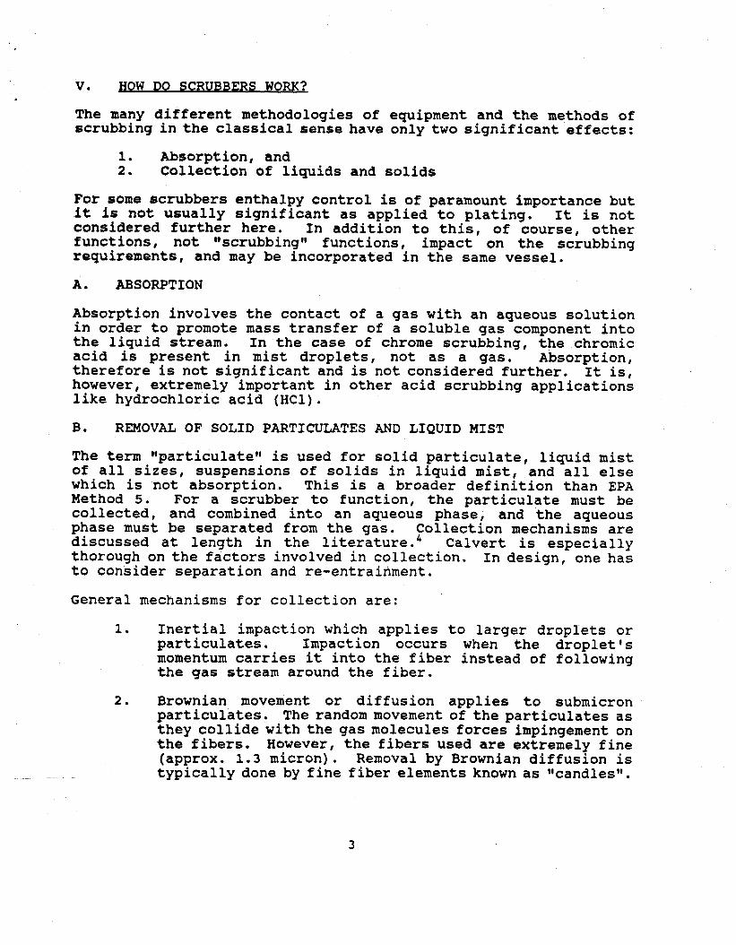
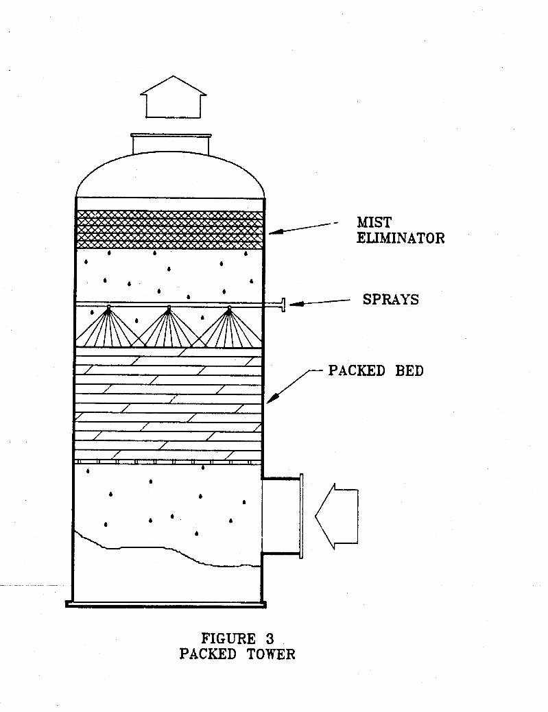
Venturi scrubbers Cross-flow scrubbers Vertical Countercurrent packed towers Cyclonic separators Spray towers
as shown in Figures 2 and 3.
The obvious and distinguishing features are ttCONTACTtt and ttSEPARATIONti of liquid. The term ttSCRUBBERtt is applied more widely today and ft actually seems quite difficult to generate definition for scrubbers.
2
V. BOW DO SCR UBBERS WORK? ,
The many different methodologies of equipment and the methods of scrubbing in the classical sense have onlytwo significant effects:
1. Absorption, and 2. Collection of liquids and solids
For some scrubbers enthalpy control is of paramount importance but it is not usually significant as applied to plating. It is not considered further here. In addition to this, of course, other functions, not @'scrubbing1' functions, impact on the scrubbing requirements, and may be incorporated in the same vessel.
A. ABSORPTION
Absorption involves the contact of a gas with an aqueous solution in order to promote mass transfer of a soluble gas component into the liquid stream. In the case of chrome scrubbing, the chromic acid is present in mist droplets, not as a gas. Absorption, therefore is not significant and is not considered further. It is, however, extremely important in other acid scrubbing applications like hydrochloric acid (HC1).
B. REMOVAL OF SOLID PARTICULATES AND LIQUID MIST
The term s particulate^^ is used for solid particulate, liquid mist of all sizes, suspensions of solids in liquid mist, and all else which is not absorption. This is a broader definition than EPA Method 5. For a scrubber to function, the particulate must be collected, and combined into an aqueous phase, and the aqueous phase must be separated from the gas. Collection mechanisms are discussed at length in the literature.4 Calvert is especially thorough on the factors involved in collection. In design, one has to consider separation and re-entrainment.
General mechanisms f o r collection are:
1. Inertial impaction which applies to larger droplets or particulates. Impaction occurs when the droplet's momentum carries it into the fiber instead of following the gas stream around the fiber.
2. Brownian movement or diffusion applies to submicron particulates. The random movement of the particulates as they collide with the gas molecules forces impingement on the fibers. However, the fibers used are extremely fine (approx. 1.3 micron). Removal by Brownian diffusion is typically done by fine fiber elements known as llcandlestt.
3

3. Interception applies to smaller droplets which are carried around fibers with the gas stream. However the inertia created by this path carries the droplet into downstream fibers. Its effect is most noticeable in the droplet size range below where inertial impaction occurs and above where diffusional impaction occurs.
The uniquely interlaced monofilament structure relies on interception and impaction mechanisms (See Figure 4). Moreover for systems to achieve the new strict standards, interception is believed to be significant. When interception and impaction are used, collection is a function of:
GEOMETRY Fiber diameter Fiber orientation Particle diameter Bed thickness FLOW Gas Velocity
mTERIAL PROPERTIES Liquid density Liquid viscosity Gas density Gas viscosity
Smaller fiber diameter, larger particles and higher velocities favor better collection. Unfortunately, the same factors favor high pluggage, high pressure drop, poor separation and increased chemical attack. These are important factors in chrome scrubber designs.
VI. "NEW TECHNOLOGY"
The technology described here has been called "newly emerging" in an EPA study for NESHAP.5 With over 10,000 installations of the structure worldwide ran ing from less than 1 CFH (0.5 l/h) to about
more than 10,000 units per month, neither the structure nor the technology can be considered new. What is this structure?
35,000,000 cfm (17000m 59 /sec) and an additional disposable use of
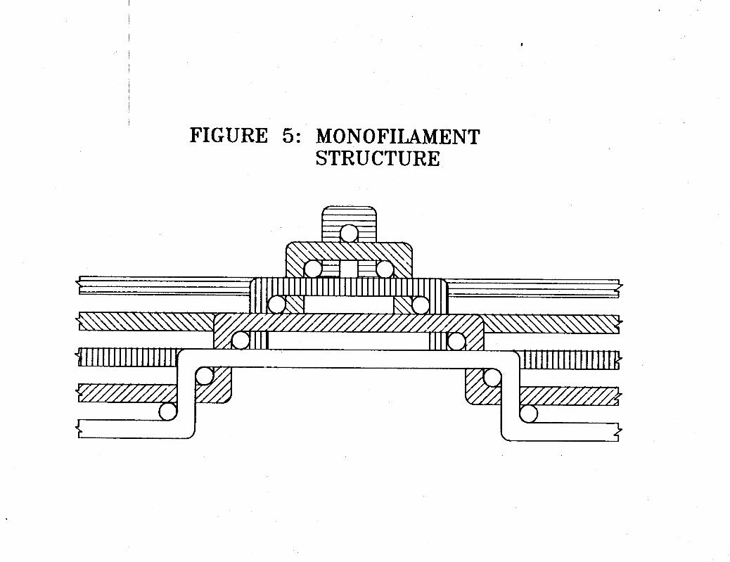
The basic media structure is made in very long pieces six feet wide and is composed of round monofilaments interlaced in a patented structure (See Figure 5). The ladder-like arrangement specifically orients the filaments to lie essentially perpendicular to the flow of the gas. Virtually any removal efficiency can be achieved by controlling:
- Fiber diameter (from .002 to.0625 inches or 50 micron to 1.6" diameter), as shown in Figure 6. - Solid fraction (from -03 to .OB) Material of construction in polypropylene, PVDF (KynarN), ETFE (Tefzel") , FEP (TeflonN), PFA (TeflonN), - Liquid rates, and Gas velocity
4

a
VII. CHROME SCRUBBER DESIGNS using the uniquely interlaced monofilament structure.
Each style of coarseness of this structure has its own performance characteristics - removal efficiency, liquid handling capacity, pluggage resistance, pressure drop, etc. Therefore, pad designs can run from simple elements comprised of one style, to more complex pads comprised of several styles-composite pads (Figure 7 )
The NESHAP report mentioned above looked at technologies used in chrome scrubbing. It summarized that ttcontrol techniques incorporating the use of a composite mesh pad appear to be the most promising of all the control options.tg.5
A composite pad utilizes the best qualities of each style to provide a more versatile arrangement than the individual styles alone could provide. Composite pads are important in chrome scrubbing because high removal efficiency, high liquid handling and reduced maintenance are critical. Troubleshooting performance problems is also made easier. Styles may simply by added or removed from composite pads to improve efficiency, pluggage resistance, pressure drop, or liquid handling capacity. This can be done very cost-effectively.
Irrigation of the media with recirculated water is recommended for optimum performance of the scrubber. Indirectly, irrigation affects the efficiency of collection. While the mechanisms of collection are unchanged with or without water, the viscous chromic acid droplets tend to cling to the media. Over time, the chrome becomes more concentrated and more viscous. This in turn increases the pressure drop, the potential for chemical attack on the fibers of the media, and the possibility of re-entrainment of the droplets due to pluggage or blinding of the fibers. Therefore, while the chrome scrubber can run ttdrytt, irrigation of the media provides longer operating cycles before maintenance is required.
In the earliest stages of chrome abatement (pre 1987) while chrome was under consideration for regulation under NESHAP, plating shops were generally interested in controlling chrome to the point where deposition on the stack and nearby buildings and automobiles was eliminated. They wanted this type of control without the need for maintenance of the scrubber unit. In these installations only coarse fiber stiles were used. The coarse styles have the efficiency to eliminate the drops that cause spotting of cars (approximately 10 microns and up), while offering the liquid handling capacity and pluggage resistance required for services where the minimum of maintenance is employed. We have received reports that units of this design have operated satisfactorily for periods up to a year before maintenance/cleaning was required.
5

Unfortunately, when units with this design were tested by the EPA for chromium emissions the performance (98% removal, .078 mg/ampere-hr) was not satisfactory for meeting the limits adopted by CARB in 1988 for medium and large hard chrome plating shops. It was clear that the size distribution of the chromic acid mist contained a significant percentage below the 8-10 micron size range. Therefore finer fiber styles would be required to meet the standards.
Composite pad mist eliminator systems then began to be employed utilizing medium to coarse fiber diameters. These designs are able to achieve removal efficiencies of 99+% for droplets 3-5 microns and up while maintaining a very reasonable amount of liquid handling capacity and pluggage resistance. Whereas, such composite structures may be able to meet emission limits for medium-sized plating shops (this design has not been tested), it is our opinion that such a design will not meet the standards for large hard chrome plating shops (99.8% or .006 mglampere-hr).
Without a reasonable size distribution available and with a need to meet the standards set forth by CARB, scrubber manufactures and end-users began to specify removal efficiencies of 99% at 1 micron and 99+% at 2 micron droplets in order to be certain to meet the limits. On top of this level of performance, the mist eliminator systems must be designed for lowest maintenance cost.
Removal efficiencies in the 1-3 micron size range necessitate using the finest fiber sizes (.002 to . 0 0 8 inches, 50 to 200 micron diameters), while the lower maintenance aspect requires coarse fiber sizes.
The basic methodology to designing a system to meet the above criteria is to collect the mist and particulates in a stage-wise approach. The design would begin with coarse fiber styles on the upstream side and gradually work down to finer styles toward the downstream. The coarse styles remove the majority of the droplets while protecting the finer styles from pluggage. The finer styles then only handle the smaller droplets ( < 3 microns) at a much lighter liquid loading.
It is possible to design a single stage mist eliminator using the uniquely interlaced monofilament structure that will achieve the CARB emission limits. However, the pad would be very deep and it would be difficult to keep the inner layers of material clean or unblinded. Therefore, due to the potential maintenance difficulties a multiple stage mist elimination system is preferred. (See Figure 8)
6

Bypassing is probablythe single-most cause for a mist eliminator's inefficiency problems. Bypassing refers to any portion of an airflow that is able to circumvent or short-circuit a mist eliminator. The airflow which bypasses a mist eliminator carries with it a certain percentage of mist or particulates. Obviously, these particulates go uncontrolled by the pad. Bypassing occurs because of fit problems between the mist eliminator and the housing or because of a design flaw in the scrubber, In either case, a single-stage mist eliminator system is more susceptible to bypass problems and has a greater potential to fail than a multiple stage system. With the exception of a serious design flaw in the vessel, the probability for gas bypassing all stages of a multiple pad arrangement is small.
Each stage of a multiple stage system has a specific design purpose.
The first stage of a multiple stage system would consist almost entirely of coarse fiber styles. This pad would eliminate essentially all of the droplets above 3-5 microns. As in the description of a composite pad above, this stage would also offer protection of finer stages downstream.
The second stage is primarily comprised of finer fiber styles. It is designed to operate as a coalescing element. In this case, the smaller chromic acid droplets (1-3 microns) are collected and agglomerated into larger, easily collectible droplets. The coalescer pad operates in a ltfloodedtl state. This means the majority of the drops collected in this pad will be re-entrained. But the droplets will be quite large (>40 microns) and, therefore, easily eliminated.
The third and final stage of the system is a simple re-entrainment separator pad comprised of medium to coarse fiber diameters. This pad merely collects any of the droplets that may re-entrain from the coalescer pad upstream.
For chrome scrubber designs, a horizontal flow with the mist eliminator pads installed vertically is preferred. Horizontal flow allows better drainage of the collected chrome. Also the pads can be designed for easy access on line for maintenance--in many cases .. without shutting the unit down.
Vertical flow scrubbers are also acceptable. The basic design principles and collection mechanisms are the same as in horizontal flow units. However, the vessel design is a little more complicated with respect to drainage and maintenance, (See Figure 91 - 4
7

The tough emission standards set down by the CARB can be met. This has been demonstrated by various technologies including units utilizing the uniquely interlaced monofilament structure. The successful application of this technology is due to the systematic interaction and cooperation between the manufacturer of this structure, a few very skilled scrubber manufacturers, and the end- users. Because of this progression of the technology, scrubber systems can vary from site to site based upon the resources available from the end-user and still be able to meet the strict standards.
Because of this versatility, chrome scrubber designs using the uniquely interlaced monofilament structure provide the most cost effective solutions to the industry's needs.
8

REFERENCES
1. Pedersen, George C., ItElectroplating: Evolution of Scrubber Technology"; presented at Eleventh AESF/EPA Environmental Control Conference, Miami, Florida, February 1990.
2 . Burkholz, Armin, IIDroplet Separationt1, VCH Publishers, New York, NY, 1989.
3 . Murcheson, Gary et at, IIProposed Airborne Toxic Control Measure for Emissions of Hexavalent Chromium from Chrome Plating and Chromic Acid Anodizing Operationst1, Prepared by State of California Air Resources Boards, January, 1988,
4 . Calvert, Seymour et al, "Wet Scrubber System Study, Volume 1, Scrubber Handbookt1, APT, Inc., Prepared for Environmental Protection Agency, July 1972.
5 . I1Chromium Electroplating Chromic Acid Anodizing - NESHAPII, briefing for National Air Pollution Control Techniques Advisory Committee, January 1991.
-.
m
u
c
FIGURE 2 17ENTURI SCRUBBER
I
/- MIST ELTMINATO
b
b
b I It
R
FIGURE 3 PACKED TOWER
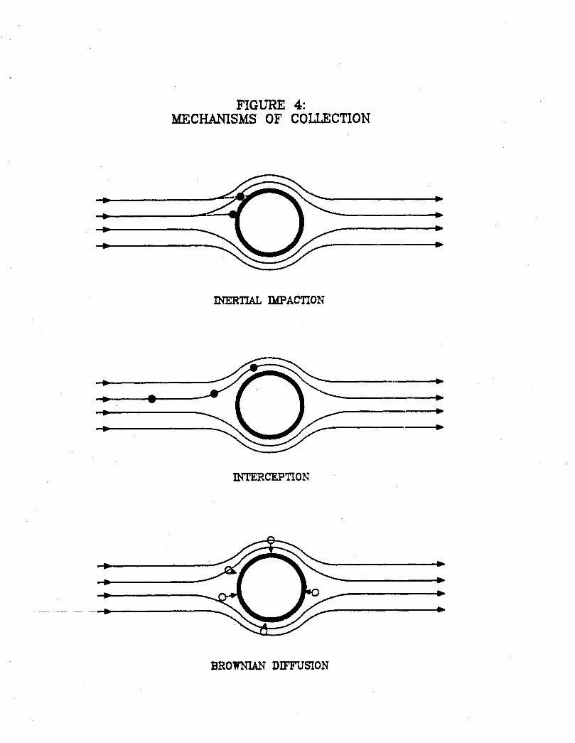
FIGURE 4: MECHAMSMS OF C O U C T I O N
b
b
b
INERTIAL IMPACTION INERTIAL IMPACTION
B R O W " DIFFUSION
.
E W

2 4 8 16 mil mil mil mil
32 37 mil mil 62
mil
l a m , BRINgS H.P. 11 MIL
FIGURE 6: FIBER SIZE COMPARISON

Y II
Q a

/ 4
0
\

FIGURE 9: VERTICAL FLOW SCRUBBER
AIRFLOW
I I I I I I I I
-- I 1 E I